WO2021070731A1 - Lighting device - Google Patents
Lighting device Download PDFInfo
- Publication number
- WO2021070731A1 WO2021070731A1 PCT/JP2020/037427 JP2020037427W WO2021070731A1 WO 2021070731 A1 WO2021070731 A1 WO 2021070731A1 JP 2020037427 W JP2020037427 W JP 2020037427W WO 2021070731 A1 WO2021070731 A1 WO 2021070731A1
- Authority
- WO
- WIPO (PCT)
- Prior art keywords
- nodule
- unit
- center
- apex
- gravity
- Prior art date
Links
Images


Classifications
-
- F—MECHANICAL ENGINEERING; LIGHTING; HEATING; WEAPONS; BLASTING
- F21—LIGHTING
- F21S—NON-PORTABLE LIGHTING DEVICES; SYSTEMS THEREOF; VEHICLE LIGHTING DEVICES SPECIALLY ADAPTED FOR VEHICLE EXTERIORS
- F21S2/00—Systems of lighting devices, not provided for in main groups F21S4/00 - F21S10/00 or F21S19/00, e.g. of modular construction
-
- F—MECHANICAL ENGINEERING; LIGHTING; HEATING; WEAPONS; BLASTING
- F21—LIGHTING
- F21S—NON-PORTABLE LIGHTING DEVICES; SYSTEMS THEREOF; VEHICLE LIGHTING DEVICES SPECIALLY ADAPTED FOR VEHICLE EXTERIORS
- F21S8/00—Lighting devices intended for fixed installation
- F21S8/04—Lighting devices intended for fixed installation intended only for mounting on a ceiling or the like overhead structures
- F21S8/06—Lighting devices intended for fixed installation intended only for mounting on a ceiling or the like overhead structures by suspension
-
- F—MECHANICAL ENGINEERING; LIGHTING; HEATING; WEAPONS; BLASTING
- F21—LIGHTING
- F21V—FUNCTIONAL FEATURES OR DETAILS OF LIGHTING DEVICES OR SYSTEMS THEREOF; STRUCTURAL COMBINATIONS OF LIGHTING DEVICES WITH OTHER ARTICLES, NOT OTHERWISE PROVIDED FOR
- F21V21/00—Supporting, suspending, or attaching arrangements for lighting devices; Hand grips
- F21V21/14—Adjustable mountings
- F21V21/30—Pivoted housings or frames
Definitions
- the present invention relates to a lighting device.
- the present invention relates to a lighting device using a surface light source such as an organic EL panel or an LED panel in which LEDs are studded in a plane shape.
- Patent Document 1 a lighting device that uses an organic EL panel as a surface light source and illuminates an indoor space with soft light close to natural light.
- Patent Document 1 has a problem that a plurality of organic EL panels are arranged in a plane, which is flat and uninteresting. Therefore, there has been a demand for a lighting device that is novel and has excellent design, which has never existed before.
- an object of the present invention is to provide a lighting device capable of three-dimensional decoration with a sense of depth.
- One aspect of the present invention for solving the above-mentioned solution has a center of gravity side knot, four apex side knots, and four connections, and the four apex side knots are each apex of the tetrahedron.
- the nodule on the side of the center of gravity is arranged at the position of the center of gravity of the tetrahedron, and the tetrahedron has at least one surface forming an equilateral triangle and three of the tetrahedrons forming the equilateral triangle.
- the lengths from the apex to the remaining vertices are equal, and the four connecting portions connect the center of gravity side nodule and each apex side nodule, and each from the center of gravity side nodule.
- the nodule on the center of gravity side extends toward the nodule on the apex side, and the nodule on the center of gravity side is a lighting device to which a surface light source is attached.
- the tetrahedron has nodules at the apex position and the center of gravity position, and the connecting portion connects these nodules, so that the entire lighting device has a three-dimensional spread. Therefore, the lighting device as a whole can have a sense of depth, and three-dimensional decoration is possible.
- the surface light source since the surface light source is attached to the nodule on the center of gravity side arranged at the position of the center of gravity of the tetrahedron, the surface light source can be stably installed with good weight balance.
- the preferred aspect is that the surface light source is attached to the opposite side of the center of gravity side nodule with respect to one connection.
- the surface light source is located on the opposite side of the one connection part and the nodule on the center of gravity side, it is easier to balance the weight.
- the preferred aspect is that the surface light source is rotatably attached to the nodule on the center of gravity side.
- the light emitting surface of the surface light source can be directed in a desired direction.
- connection portion has a mirror surface in part or in whole on the outer surface.
- the synchrotron radiation emitted from natural light or a surface light source and its reflected light, the synchrotron radiation emitted from other lighting devices and its reflected light, etc. are reflected at the connection portion, and a gorgeous appearance can be exhibited. it can.
- a preferred aspect is to have a wiring member including a first wiring portion, a second wiring portion, and a wiring portion for a light source, and the first wiring portion has a center of gravity along one connection portion from one apex side knot portion side.
- the second wiring portion extends toward the side knot portion, branches from the first wiring portion, extends toward another apex side knot portion along the other connection portion, and is the wiring for the light source.
- the unit is branched from the first wiring unit and connected to the surface light source so that power can be supplied.
- the second wiring unit and the wiring unit for the light source have the same potential when energized. ..
- the second wiring portion and the light source wiring portion have the same potential when energized, so that the surface from the light source wiring portion While supplying power to the light source, it can also supply power to the load.
- connection portion is a hollow body having a space inside
- the wiring member is such that the first wiring portion extends through the space of the connection portion and the first wiring portion extends in the center-of-gravity side nodule portion. 2 It is to branch into the wiring part and the wiring part for the light source.
- connection part and the nodule on the center of gravity side it is possible to supply power to the surface light source by passing through the space inside the connection part and the nodule on the center of gravity side. Therefore, a part or all of the wiring member is hidden by the connecting portion and the nodule on the center of gravity side, so that the wiring member can be obscured in appearance. Further, a part or all of the wiring member is protected by the connecting portion and the nodule on the center of gravity side, and the wiring member can be prevented from being disconnected.
- a preferred aspect is a lighting device that is attached by hanging from the attached portion, and one of the four connecting portions extends in the vertical direction in a state of being hung from the attached portion. It is that you are.
- attached portion refers to a portion to be attached to the lighting device, and includes, for example, structures such as ceilings, walls, and floors.
- connection part and the surface light source overlap in the vertical direction, the weight balance is good and it can hang down stably from the attached part.
- the second surface light source is attached to each of the three apex-side nodules connected to the other three connection portions among the four connection portions, and each second surface light source is the above three. It is located above the two apex-side nodules and is attached in the extending direction of the one connecting portion.
- each second surface light source is mounted on the same side in the vertical direction, the weight balance becomes better.
- the preferred aspect is that the center-of-gravity nodule, the four apex-side nodules, and the four connections form a diamond crystal structure of a ball-and-stick model.
- the unit portion has a plurality of unit portions, and the unit portion is composed of the center of gravity side nodule portion, the four apex side nodules, and the four connecting portions, and is between two adjacent unit portions. Has a shared nodule that shares the apex nodule.
- the number of parts can be reduced because the apex side nodule can be shared between adjacent unit parts.
- the plurality of unit portions include a first unit portion, a second unit portion, and a third unit portion, and an apical nodule portion is provided between the first unit portion and the second unit portion.
- the center of gravity side nodule of the unit, the first shared nodule, the second shared nodule, and the third shared nodule are each connected by the connecting portion to form an annular portion, and are of a chair type. It is a positional relationship of three-dimensional seating.
- the center-of-gravity nodule of the first unit the center-of-gravity nodule of the second unit, the center-of-gravity nodule of the third unit, the first shared nodule, and the second shared nodule.
- the part and the third common nodule part have a positional relationship of a chair-shaped conformation. Therefore, there is almost no three-dimensional distortion, and the structural stability is high.
- FIG. 6 It is a perspective view which shows typically the lighting apparatus of 1st Embodiment of this invention. It is a perspective view of the unit part of FIG. It is a perspective view of the unit part of FIG. 1, and is the perspective view seen from the direction different from FIG. It is a cross-sectional perspective view of the unit body of FIG. It is sectional drawing of the apex side nodule part of FIG. It is a conceptual diagram of the unit part of FIG. It is explanatory drawing of the unit part of FIG. 6, (a) is a conceptual diagram which shows the 2nd stage unit part, and (b) is a conceptual diagram which shows the 3rd stage unit part. It is an exploded perspective view of the surface light source part of FIG.
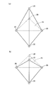
- FIG. 1 It is a perspective view which shows typically the lighting apparatus of 2nd Embodiment of this invention. It is a perspective view of the unit part of FIG. It is a perspective view which shows the unit part of another embodiment of this invention schematically, (a) is a tetrahedron structure which is higher than a regular tetrahedron, (b) is a regular tetrahedron. On the other hand, it represents a case where a tetrahedral structure having a low height is adopted. It is a perspective view which shows typically the installation state of the lighting apparatus of another embodiment of this invention.
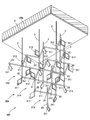
- the lighting device 1 of the first embodiment of the present invention is a decorative lighting device that is attached to a mounted surface 200 (mounted portion) such as a ceiling surface.
- the lighting device 1 is mainly composed of a base portion 2, a hanging portion 3, a unit portion 5, and a wiring member 6 (see FIGS. 4 and 5).
- the base portion 2 is a plate-like body attached to the attached surface 200, and is fixed in surface contact with the attached surface 200 by an attachment means such as a fastening element or an adhesive (not shown). It is a part.
- the hanging portion 3 is a portion that connects the base portion 2 and the unit portion 5 and suspends the unit portion 5 with respect to the base portion 2. That is, the hanging portion 3 can be supported by hanging the unit portion 5 with respect to the base portion 2.
- the hanging portion 3 of the present embodiment is a string-shaped body or a rod-shaped body extending in a predetermined direction.
- the unit unit 5 is composed of a plurality of unit bodies 10 and a plurality of surface light source units 11 and 12, and the unit bodies 10 are connected in a stepped manner and spread three-dimensionally.
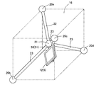
- the unit body 10 includes an apex side nodule portion 20 (20a to 20d), a center of gravity side nodule portion 21, a first connection portion 22, and a second connection portion 23.
- the unit body 10 constitutes a diamond crystal structure of a ball-and-stick model by four apex-side nodules 20a to 20d, a center-of-gravity-side nodule 21, and connection portions 22 and 23. ing. That is, the nodule portions 20 and 21 correspond to balls (atoms), and the connection portions 22 and 23 correspond to sticks.
- the apex-side nodule portions 20a to 20d are portions arranged at each apex position of the regular tetrahedron 15 (regular triangular pyramid) as shown in FIG. 2, and are also arranged at the apex positions of the cube 16 as shown in FIG. Is.
- the apex-side nodule 20 is a hollow body having a substantially spherical shape and an internal space 26, and the outer surface is a mirror surface.
- the apex side nodule portion 20 includes a plurality of attachment portions 27 to 29.
- the mounting portions 27 to 29 are communication holes extending from the outer surface toward the space 26 and communicating with the space 26.
- the mounting portions 27 and 28 are extension holes extending in the vertical direction so as to be close to each other when the lighting device 1 is mounted on the mounted surface 200, and are arranged in the vertical direction. That is, the first attachment portion 27 is provided at the top of the apex side nodule portion 20, and the second attachment portion 28 is provided at the bottom of the apex side nodule portion 20.
- the mounting portion 29 extends in a direction intersecting the vertical direction when the lighting device 1 is mounted on the mounted surface 200. That is, the central axis of the mounting portion 29 intersects the central axis of the mounting portions 27 and 28 and extends diagonally upward.
- the first mounting portion 27 can mount the apex side light source portion 11 by inserting the mounting portion 51 of the apex side light source portion 11.
- the first connection portion 22 can be attached to the second attachment portion 28 by inserting the first connection portion 22.
- the second connection portion 23 can be attached to the third attachment portion 29 by inserting the second connection portion 23.
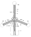
- the center-of-gravity side nodule 21 is a portion arranged at the center-of-gravity position of the regular tetrahedron 15 as shown in FIG. 2, and is also a portion arranged at the center position of the cube 16 as shown in FIG. As shown in FIGS. 2 and 4, the center-of-gravity side nodule 21 is a hollow body having a substantially spherical shape and a space 36 inside, and the outer surface is a mirror surface.
- the center-of-gravity side nodule portion 21 includes a plurality of attachment portions 37 to 41.
- the mounting portions 37 to 41 are communication holes extending from the outer surface toward the space 36 and communicating with the space 36.
- the mounting portions 37 and 38 are extension holes extending in the vertical direction so as to be close to each other when the lighting device 1 is mounted on the mounted surface 200, and are arranged in the vertical direction. That is, the first mounting portion 37 is provided at the top of the center of gravity side nodule portion 21, and the second mounting portion 38 is provided at the bottom of the center of gravity side nodule portion 21.
- the mounting portions 39 to 41 are holes arranged side by side at intervals in the circumferential direction with respect to the central axes of the mounting portions 37 and 38.
- the mounting portions 39 to 41 extend in a direction intersecting the vertical direction when the lighting device 1 is mounted on the mounted surface 200. That is, the central axes of the mounting portions 39 to 41 intersect the central axes of the mounting portions 37 and 38 and extend diagonally downward.
- the first connection portion 22 can be attached to the first attachment portion 37 by inserting the first connection portion 22.
- the second mounting portion 38 can mount the center of gravity side light source portion 12 by inserting the mounting portion 51 of the center of gravity side light source portion 12.
- the second connection portion 23 By inserting the second connection portion 23 into each of the third attachment portions 39 to 41, the second connection portion 23 can be attached to each of the third attachment portions 39 to 41.
- the first connecting portion 22 is a portion connecting the apex side nodule portion 20a and the center of gravity side nodule portion 21, and is an extending portion extending in a predetermined direction.
- the first connecting portion 22 has a cylindrical shape, has a space 46 inside, and has a mirror surface on the outer surface.
- the second connecting portion 23 is a portion connecting the center-of-gravity side nodule portion 21 and the apex side nodule portion 20b to 20d, and is an extending portion extending in a direction different from that of the first connecting portion 22. Is.
- the second connecting portion 23 has a cylindrical shape, has a space 56 inside, and has a mirror surface on the outer surface.
- the apex side light source portion 11 includes a light emitting panel 50 and a mounting portion 51.
- the light emitting panel 50 is a planar light emitting panel in which one side is a light emitting surface, the light emitting surface emits light in a planar manner, and diffused light is emitted.
- the light emitting panel 50 is an organic EL panel.
- the light emitting panel 50 of the present embodiment is a square plate-shaped panel having a planar spread.
- the light emitting panel 50 may be an LED panel in which LEDs are studded in a plane shape.
- the attachment portion 51 is a portion for rotatably attaching the light emitting panel 50 to the first attachment portion 27 of the apex side nodule portion 20.
- the apex side light source portion 11 of the present embodiment includes a bearing portion 52 on the back surface of the light emitting panel 50, and a shaft portion 53 on the mounting portion 51. Then, in the apex side light source unit 11, the shaft portion 53 of the mounting portion 51 is inserted into the bearing portion 52 of the light emitting panel 50, and the light emitting panel 50 can rotate around the shaft portion 53 in the circumferential direction.
- the center-of-gravity side light source unit 12 is a member similar to the apex side light source unit 11 and has the same configuration as the apex side light source unit 11, the same configuration is designated by the same reference numerals and description thereof will be omitted.
- the center of gravity side light source unit 12 includes a light emitting panel 50 and a mounting portion 51, and the mounting portion 51 attaches the light emitting panel 50 to the second mounting portion 38 of the center of gravity side nodule portion 21. It can be mounted rotatably. That is, in the center of gravity side light source unit 12, the light emitting panel 50 can rotate around the shaft portion 53 of the mounting portion 51 in the circumferential direction.
- the wiring member 6 is a power supply wiring for supplying power from an external power source to the light source units 11 and 12 on each surface, and has a positive wiring and a negative wiring built therein. As shown in FIGS. 4 and 5, the wiring member 6 is composed of a main wiring portion 70, a wiring portion 71 for a first light source, and a wiring portion 72 for a second light source.
- the main wiring portion 70 is a wiring that crawls mainly inside the unit body 10, and is a connection wiring for electrically connecting from the apex-side nodule 20a at the base end to each apex-side nodule 20b to 20d at the end. ..
- the main wiring portion 70 is configured by alternately arranging the first wiring portion 75 and the second wiring portion 76.
- the first wiring portion 75 is a wiring portion that extends from the apex side nodule portion 20a toward the center of gravity side nodule portion 21 and connects the apex side nodule portion 20a and the center of gravity side nodule portion 21.
- the second wiring portion 76 is connected to the end portion of the first wiring portion 75, extends from the center of gravity side nodule portion 21 toward the apex side nodule portion 20b to 20d, and extends from the center of gravity side nodule portion 21 to the apex side nodule portion 20b to 20d. It is a wiring part to connect.
- the first light source wiring unit 71 is a branch wiring branched from the intermediate portion of the main wiring unit 70, and is a power supply wiring for supplying power to the center of gravity side light source unit 12.
- the first light source wiring unit 71 is wiring branched from the end of the first wiring unit 75, and is the same as the second wiring unit 76 separately branched from the first wiring unit 75 when energized. It is an electric potential.
- the second light source wiring unit 72 is a branch wiring branched from the intermediate portion of the main trunk wiring unit 70 as shown in FIG. 5, and is a power supply wiring for supplying power to the apex side light source unit 11.
- the second light source wiring unit 72 is wiring branched from the end of the second wiring unit 76, and is the same as the first wiring unit 75 separately branched from the second wiring unit 76 when energized. It is an electric potential.
- the lighting device 1 has a base portion 2 attached to a surface to be attached 200 by a fixing means (not shown).
- the hanging portion 3 extends in the vertical direction, and the lower end portion is connected to the apex side knot portion 20a of the first stage.
- the apex side nodule 20a is connected to the center of gravity side nodule 21 via the first connection 22 as shown in FIG. 2, and the center of gravity side nodule 21 is connected to each second connection. It is connected to the apex side nodule portions 20b to 20d via the portion 23.
- the first mounting portion 27 is connected to the hanging portion 3 (first stage) or the apex side light source portion 11 (second and subsequent stages), and the second mounting portion 28. Is connected to the first connecting portion 22, and the third mounting portion 29 is connected to the second connecting portion 23.
- the center of gravity side nodule portion 21 has a first attachment portion 37 connected to the first connection portion 22, a second attachment portion 38 connected to the center of gravity side light source portion 12, and a third attachment portion 21.
- Units 39 to 41 are connected to each second connection unit 23.
- the lighting device 1 has a plurality of locations that share the apex-side nodules 20a to 20d among the unit bodies 10.
- the apex-side nodules 20b to 20d of the first-stage unit bodies 10a are shared nodules that also serve as the apex-side nodules 20a of the second-stage unit bodies 10b to 10d. That is, the apex-side nodule portions 20b to 20d of the first-stage unit body 10a are connected to the second attachment portion 28 with the first connection portion 22 as shown in FIG.
- the apex-side nodule portion 20c is a shared nodule portion that also serves as the apex-side nodule portion 20b of the second-stage unit body 10c, and is on the apex side.
- the nodule 20d is a shared nodule that also serves as the apex-side nodule 20b of the second-stage unit body 10d.
- the second-stage unit body 10c is a shared knot portion in which the apex-side nodule portion 20d also serves as the apex-side nodule portion 20c of the second-stage unit body 10d. That is, the second connecting portion 23 of the unit body 10 adjacent to the mounting portion 29 is inserted into each of the apex-side nodule portions 20 of the second-stage unit bodies 10b to 10d.
- the lighting device 1 includes the center-of-gravity side nodule 21 of each of the second-stage unit bodies 10b to 10d, the shared apex side nodule 20, and these.
- the annular portion 80 is formed by the second connecting portion 23 connecting the nodule portions 20.
- the nodule portions 20 and 21 constituting the annular portion 80 have a positional relationship of chair-shaped conformation.
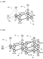
- the apex-side nodule portions 20b to 20d of the second-stage unit bodies 10b to 10d are shared nodule portions that also serve as the apex-side nodule portions 20a of the third-stage unit bodies 10e to 10j. .. That is, the apex-side nodule portions 20b to 20d of the second-stage unit bodies 10b to 10d are connected to the second attachment portion 28 by the first connection portion 22.
- the third-stage unit bodies 10e to 10j share the apex-side nodule portions 20b to 20d among the adjacent unit bodies 10 as in the second-stage unit bodies 10b to 10d.
- the second connecting portion 23 of the adjacent unit body 10 is inserted into each apex side nodule portion 20.
- the lighting device 1 has the center-of-gravity side nodule 21 of each of the third-stage unit bodies 10e to 10j, the shared apex side nodule 20, and these nodule 20.
- a plurality of annular portions 80 are configured by the second connecting portion 23 to be connected.
- the nodule portions 20 and 21 constituting the annular portion 80 have a positional relationship of chair-shaped conformation.
- the apex side light source unit 11 is located on the extension of the first connection unit 22 in the extending direction.
- the apex side light source portion 11 and the first connecting portion 22 are arranged at positions facing each other with the apex side nodule portions 20b to 20d interposed therebetween. That is, the apex side light source unit 11 is on the side opposite to the connection portion of the apex side nodule portions 20b to 20d with the first connection portion 22, and is located on the upper side in the vertical direction.
- the shaft portion 53 is located on an extension of the central axis of the first connecting portion 22, and the light emitting panel 50 is rotatable around the shaft portion 53.
- the center-of-gravity side light source unit 12 is located on the extension of the first connection unit 22 in the extending direction and on the opposite side of the apex side surface light source unit 11.
- the center of gravity side light source portion 12 and the first connecting portion 22 are arranged at positions facing each other with the center of gravity side nodule portion 21 interposed therebetween. That is, the center-of-gravity side light source unit 12 is on the side opposite to the connection portion of the center-of-gravity side nodule portion 21 with the first connection portion 22, and is located on the lower side in the vertical direction.
- the shaft portion 53 is located on an extension of the central axis of the first connecting portion 22, and the light emitting panel 50 can rotate around the shaft portion 53.
- the apex side knot portion 20 is arranged at the apex position of the regular tetrahedron 15 which is a regular polyhedron having the smallest number of vertices, sides, and faces. Therefore, it can be formed at low cost, and three-dimensional decoration with a sense of depth is possible.
- the nodules 20 and 21 are evenly and most spaced in a certain space. Therefore, even with a simple configuration, a beautiful appearance can be exhibited.
- the illumination device 1 of the present embodiment even when observed from all directions, the overlap of the synchrotron radiation from the surface light source units 11 and 12 is minimized, and a wider range can be illuminated. Therefore, energy saving is possible.
- each center of gravity side nodule portion 21 is systematically supported by the second connecting portion 23. Therefore, it is highly stable and highly reliable.
- a surface light source is used as a light source. Therefore, as compared with the LED which is a point light source, the perspective effect can be easily obtained and the effectability is excellent.
- each apex side nodule portion 20 and each connection portion 22 and 23 have the same shape, they can be made into the same member, and can be manufactured inexpensively and easily.
- the unit unit 5 has a regular tetrahedron structure, and the surface light source units 11 and 12 are provided at positions where there is little steric hindrance. Therefore, the connecting portions 22 and 23 are less likely to interfere with each other, and the surface light source portions 11 and 12 can be easily rotated.
- the lighting device 1 of the present embodiment since the surface light source portions 11 and 12 are rotatable with respect to the nodule portions 20 and 21, the light emitting surface can obtain an appropriate decorative effect according to the installation location.
- the angle of the can be adjusted, and the degree of freedom of decoration is high.
- the surface light source units 11 and 12 are connected in parallel to the external power source and have the same potential. Therefore, the entire wiring member 6 can be simplified, and the surface light source portions 11 and 12 can be easily replaced and the unit portion 5 can be easily expanded.
- the first connecting portion 22 connecting the apex side nodule portion 20a and the center of gravity side nodule portion 21 extends in the vertical direction, and the remaining apex side nodule portions 20b to 20d form a vertical axis. It is rotationally symmetric three times with respect to the center line of the connecting portion 22. Therefore, the mutual arrangement of the nodules 20 and 21 is stable, the weight of the lighting device 1 as a whole is easily balanced, and the stability is excellent.
- the unit portion 5 has a diamond crystal structure having the nodule portions 20 and 21 as atomic positions. Therefore, it becomes a decorative lighting device with a novel design that has never existed before.
- the annular portion 80 is formed by the center-of-gravity side nodule portion 21 of the second-stage unit bodies 10b to 10d, the apex side nodule portion 20 constituting the shared nodule portion, and the connecting portions 22, 23. It is configured. Then, according to the illumination device 1 of the present embodiment, the nodules 20 and 21 constituting the annular portion 80 have a positional relationship of the chair conformation, such as the carbon group of cyclohexane in the chair conformation. It has become. Therefore, there is almost no three-dimensional distortion, and the structural stability is high.
- the lighting device 300 according to the second embodiment of the present invention will be described.
- the same configuration as that of the lighting device 1 of the first embodiment is designated by the same reference numerals and the description thereof will be omitted. The same shall apply hereinafter.
- the postures of the lighting device 1 and the unit unit 5 of the first embodiment are reversed as shown in FIGS. 9 and 10. That is, in the lighting device 300, the top and bottom of the unit portion 5 are reversed.
- the lighting device 300 includes a base portion 2, a hanging portion 3, and a unit portion 305.
- the unit unit 305 is composed of a plurality of unit bodies 310 and a plurality of surface light source units 311, 312, and the unit body 310 is spread out in a plurality of stages.
- the surface light source portions 311, 312 form a universal joint with the light emitting panel 350 and the mounting portion 351 so that the joining angle can be freely changed.
- the light emitting panel 350 is a panel similar to the light emitting panel 50, and the mounting portion 351 is mounted on the corner portion of the light emitting panel 350.
- the light emitting panel 350 and the mounting portion 351 form a universal joint, the light emitting surface of the light emitting panel 350 can be directed in a desired direction, and the degree of freedom of decoration is increased. high.
- the light emitting panels 50 and 350 have a front view shape, but the present invention is not limited to this, and the shapes of the light emitting panels 50 and 350 are not limited.
- it may be a polygonal shape such as a front view triangle, a pentagon, or a hexagon, or it may be a circular shape or an elliptical shape.
- the wiring member 6 crawls into the spaces 26, 36, 46, 56 inside the unit body 10, but the present invention is not limited to this.
- the wiring member 6 may be partially or wholly exposed to the outside of the unit body 10.
- the apex-side nodule 20 is arranged at the apex position of the regular tetrahedron 15, but the present invention is not limited to this.
- the apex-side nodule 20 may be arranged at the apex position of a tetrahedron having at least one surface of an equilateral triangle and having the same length from the three vertices of the equilateral triangle to the remaining vertices.
- each vertex-side nodule 20 may be arranged at each vertex position of the tetrahedron whose height is higher than that of the regular tetrahedron 15 as shown in FIG. 11 (a), or FIG. 11 (b).
- the position of the center of gravity is located on an axis orthogonal to the position of the center of gravity of the equilateral triangle.
- the unit portion 5 is suspended from the attached surface 200 by the suspending portion 3, but the present invention is not limited to this.
- the mounted surface 200 is a wall surface or a floor surface
- the unit portion 5 may be fixed to the mounted surface 200 by a rigid support member.
- the unit unit 5 may have one or two stages, or may have four or more stages.
- the first connecting portion 22 of the lower unit portion 5 is connected to all the apex-side nodule portions 20 in the upper stage, but the present invention is not limited to this.
- the first connecting portion 22 of the lower unit portion 5 may be connected only to a part of the apex side nodule portion 20.
- the hanging portion 3 is attached to the attached surface 200 via the base portion 2, but the present invention is not limited to this.
- the hanging portion 3 may be directly attached to the attached surface 200 without going through the base portion 2.
- a plurality of lighting devices 1 may be laid on the mounted surface 200 in a planar manner. In this case, it is preferable to spread the base portion 2 of each lighting device 1 so as to be tessellated.
- the case where one lighting device 300 is attached to the attached surface 200 has been described, but the present invention is not limited thereto.
- a plurality of lighting devices 300 may be laid on the mounted surface 200 in a planar manner.
Abstract
The lighting device has a configuration comprising a center-of-gravity-side node part, four vertex-side node parts, and four connection parts, wherein the four vertex-side node parts are arranged so as to correspond to the respective vertices of a tetrahedron including at least one regular triangular face, the center-of-gravity-side node part is disposed at the center of gravity of the tetrahedron, the four connection parts are for connecting the center-of-gravity-side node part with the respective vertex-side node parts and extend from the center-of-gravity-side node part toward the respective vertex-side node parts, and a surface light source is attached to the center-of-gravity-side node part.
Description
本発明は、照明装置に関する。特に本発明は、有機ELパネルやLEDを面状に散りばめたLEDパネル等の面光源を用いた照明装置に関する。
The present invention relates to a lighting device. In particular, the present invention relates to a lighting device using a surface light source such as an organic EL panel or an LED panel in which LEDs are studded in a plane shape.
従来から、面光源として有機ELパネルを使用し、自然光に近い柔らかい光で室内空間を照らす照明装置が知られている(例えば、特許文献1)。
Conventionally, there is known a lighting device that uses an organic EL panel as a surface light source and illuminates an indoor space with soft light close to natural light (for example, Patent Document 1).
しかしながら、特許文献1に記載の照明装置は、複数の有機ELパネルが平面状に並べられており、平面的で面白味がないという問題があった。そのため、従来にはない斬新で意匠性に優れた照明装置が望まれていた。
However, the lighting device described in Patent Document 1 has a problem that a plurality of organic EL panels are arranged in a plane, which is flat and uninteresting. Therefore, there has been a demand for a lighting device that is novel and has excellent design, which has never existed before.
そこで、本発明は、奥行き感がある立体的な装飾が可能な照明装置を提供することを目的とする。
Therefore, an object of the present invention is to provide a lighting device capable of three-dimensional decoration with a sense of depth.
上記した解決するための本発明の一つの様相は、重心側結節部と、4つの頂点側結節部と、4つの接続部を有し、前記4つの頂点側結節部は、四面体の各頂点をなすように配されており、前記重心側結節部は、前記四面体の重心位置に配されており、前記四面体は、少なくとも一面が正三角形を構成し、前記正三角形を構成する三つの頂点からの残りの頂点までの長さが等しいものであり、前記4つの接続部は、前記重心側結節部と各頂点側結節部を接続するものであって、かつ前記重心側結節部から各頂点側結節部に向かって延びており、前記重心側結節部は、面光源が取り付けられている、照明装置である。
One aspect of the present invention for solving the above-mentioned solution has a center of gravity side knot, four apex side knots, and four connections, and the four apex side knots are each apex of the tetrahedron. The nodule on the side of the center of gravity is arranged at the position of the center of gravity of the tetrahedron, and the tetrahedron has at least one surface forming an equilateral triangle and three of the tetrahedrons forming the equilateral triangle. The lengths from the apex to the remaining vertices are equal, and the four connecting portions connect the center of gravity side nodule and each apex side nodule, and each from the center of gravity side nodule. The nodule on the center of gravity side extends toward the nodule on the apex side, and the nodule on the center of gravity side is a lighting device to which a surface light source is attached.
本様相によれば、四面体の頂点位置と重心位置に結節部をもち、これらの結節部を接続部が繋ぐので、照明装置全体として三次元的に広がりがある。そのため、照明装置全体として奥行き感を持たせることができ、立体的な装飾が可能である。
本様相によれば、四面体の重心位置に配された重心側結節部に面光源が取り付けられているため、重量バランスが良好で安定して面光源を設置できる。 According to this aspect, the tetrahedron has nodules at the apex position and the center of gravity position, and the connecting portion connects these nodules, so that the entire lighting device has a three-dimensional spread. Therefore, the lighting device as a whole can have a sense of depth, and three-dimensional decoration is possible.
According to this aspect, since the surface light source is attached to the nodule on the center of gravity side arranged at the position of the center of gravity of the tetrahedron, the surface light source can be stably installed with good weight balance.
好ましい様相は、前記面光源は、一の接続部に対して前記重心側結節部の反対側に取り付けられていることである。
The preferred aspect is that the surface light source is attached to the opposite side of the center of gravity side nodule with respect to one connection.
本様相によれば、面光源が一の接続部と重心側結節部を挟んで反対側に位置するため、より重量バランスがとりやすい。
According to this aspect, since the surface light source is located on the opposite side of the one connection part and the nodule on the center of gravity side, it is easier to balance the weight.
好ましい様相は、前記面光源は、前記重心側結節部に対して回動可能に取り付けられていることである。
The preferred aspect is that the surface light source is rotatably attached to the nodule on the center of gravity side.
本様相によれば、面光源の発光面を回動させることで、面光源の発光面を所望の方向に向けることができる。
According to this aspect, by rotating the light emitting surface of the surface light source, the light emitting surface of the surface light source can be directed in a desired direction.
好ましい様相は、前記接続部は、外面の一部又は全部が鏡面となっていることである。
The preferred aspect is that the connection portion has a mirror surface in part or in whole on the outer surface.
本様相によれば、自然光や面光源から放射される放射光及びその反射光、他の照明装置から放射される放射光やその反射光等が接続部で反射され、煌びやかな外観を呈することができる。
According to this aspect, the synchrotron radiation emitted from natural light or a surface light source and its reflected light, the synchrotron radiation emitted from other lighting devices and its reflected light, etc. are reflected at the connection portion, and a gorgeous appearance can be exhibited. it can.
好ましい様相は、第1配線部と第2配線部と光源用配線部を含む配線部材を有し、前記第1配線部は、一の頂点側結節部側から一の接続部に沿って前記重心側結節部に向かって延びており、前記第2配線部は、前記第1配線部から分岐し、他の接続部に沿って他の頂点側結節部に向かって延びており、前記光源用配線部は、前記第1配線部から分岐し、前記面光源に接続されて給電可能となっており、前記第2配線部と前記光源用配線部は、通電時において、同電位であることである。
A preferred aspect is to have a wiring member including a first wiring portion, a second wiring portion, and a wiring portion for a light source, and the first wiring portion has a center of gravity along one connection portion from one apex side knot portion side. The second wiring portion extends toward the side knot portion, branches from the first wiring portion, extends toward another apex side knot portion along the other connection portion, and is the wiring for the light source. The unit is branched from the first wiring unit and connected to the surface light source so that power can be supplied. The second wiring unit and the wiring unit for the light source have the same potential when energized. ..
本様相によれば、例えば、第2配線部に他の面光源等の負荷を取り付けた場合に、通電時に第2配線部と光源用配線部が同電位となるため、光源用配線部から面光源に給電しつつ、負荷に対しても給電できる。
According to this aspect, for example, when a load such as another surface light source is attached to the second wiring portion, the second wiring portion and the light source wiring portion have the same potential when energized, so that the surface from the light source wiring portion While supplying power to the light source, it can also supply power to the load.
より好ましい様相は、前記接続部は、内部に空間がある中空体であり、前記配線部材は、前記第1配線部が前記接続部の前記空間を通って延び、前記重心側結節部内で前記第2配線部と前記光源用配線部に分岐することである。
A more preferable aspect is that the connection portion is a hollow body having a space inside, and the wiring member is such that the first wiring portion extends through the space of the connection portion and the first wiring portion extends in the center-of-gravity side nodule portion. 2 It is to branch into the wiring part and the wiring part for the light source.
本様相によれば、接続部や重心側結節部の内部の空間を通過して面光源に給電可能である。そのため、配線部材の一部又は全部が接続部や重心側結節部によって隠されて、配線部材を外観上見えにくくできる。また、配線部材の一部又は全部が接続部や重心側結節部によって保護されて、配線部材の断線等も防止できる。
According to this aspect, it is possible to supply power to the surface light source by passing through the space inside the connection part and the nodule on the center of gravity side. Therefore, a part or all of the wiring member is hidden by the connecting portion and the nodule on the center of gravity side, so that the wiring member can be obscured in appearance. Further, a part or all of the wiring member is protected by the connecting portion and the nodule on the center of gravity side, and the wiring member can be prevented from being disconnected.
好ましい様相は、被取付部に対して垂下されて取り付けられる照明装置であって、前記4つの接続部のうち一の接続部は、前記被取付部から垂下された状態において、鉛直方向に延びていることである。
A preferred aspect is a lighting device that is attached by hanging from the attached portion, and one of the four connecting portions extends in the vertical direction in a state of being hung from the attached portion. It is that you are.
ここでいう「被取付部」とは、照明装置の取付対象部位をいい、例えば、天井や壁、床等の構造物を含む。
The term "attached portion" as used herein refers to a portion to be attached to the lighting device, and includes, for example, structures such as ceilings, walls, and floors.
本様相によれば、接続部と面光源が鉛直方向に重なるので、重量バランスが良好であり、安定して被取付部から垂下できる。
According to this aspect, since the connection part and the surface light source overlap in the vertical direction, the weight balance is good and it can hang down stably from the attached part.
より好ましい様相は、前記4つの接続部のうち他の3つの接続部と接続される3つの頂点側結節部は、第2面光源がそれぞれ取り付けられており、各第2面光源は、前記3つの頂点側結節部の上方側にあって、前記一の接続部の延び方向に取り付けられていることである。
In a more preferable aspect, the second surface light source is attached to each of the three apex-side nodules connected to the other three connection portions among the four connection portions, and each second surface light source is the above three. It is located above the two apex-side nodules and is attached in the extending direction of the one connecting portion.
本様相によれば、各第2面光源が鉛直方向の同一側に取り付けられているため、より重量バランスが良好となる。
According to this aspect, since each second surface light source is mounted on the same side in the vertical direction, the weight balance becomes better.
好ましい様相は、前記重心側結節部と前記4つの頂点側結節部と前記4つの接続部は、ボールアンドスティックモデルのダイヤモンド結晶構造を構成することである。
The preferred aspect is that the center-of-gravity nodule, the four apex-side nodules, and the four connections form a diamond crystal structure of a ball-and-stick model.
本様相によれば、従来にはない独創的な外観となり、意匠性が高い。
According to this aspect, it has an unprecedented original appearance and is highly designed.
好ましい様相は、複数のユニット部を有し、前記ユニット部は、前記重心側結節部と前記4つの頂点側結節部と前記4つの接続部で構成されており、隣接する2つのユニット部の間には、頂点側結節部を共有する共有結節部があることである。
A preferred aspect is that the unit portion has a plurality of unit portions, and the unit portion is composed of the center of gravity side nodule portion, the four apex side nodules, and the four connecting portions, and is between two adjacent unit portions. Has a shared nodule that shares the apex nodule.
本様相によれば、隣接するユニット部間で頂点側結節部を共有できるので、部品点数を削減できる。
According to this aspect, the number of parts can be reduced because the apex side nodule can be shared between adjacent unit parts.
より好ましい様相は、前記複数のユニット部には、第1ユニット部と第2ユニット部と第3ユニット部があり、前記第1ユニット部と前記第2ユニット部の間には、頂点側結節部を共有する第1共有結節部があり、前記第2ユニット部と前記第3ユニット部の間には、頂点側結節部を共有する第2共有結節部があり、前記第3ユニット部と前記第1ユニット部の間には、頂点側結節部を共有する第3共有結節部があり、前記第1ユニット部の重心側結節部と、前記第2ユニット部の重心側結節部と、前記第3ユニット部の重心側結節部と、前記第1共有結節部と、前記第2共有結節部と、前記第3共有結節部は、それぞれ前記接続部で接続されて環状部を構成し、いす型の立体配座の位置関係となっていることである。
A more preferable aspect is that the plurality of unit portions include a first unit portion, a second unit portion, and a third unit portion, and an apical nodule portion is provided between the first unit portion and the second unit portion. There is a first shared nodule that shares the same, and between the second unit and the third unit, there is a second shared nodule that shares the apical nodule, and the third unit and the third unit share the same. Between the 1 unit portions, there is a third shared nodule portion that shares the apical side nodule portion, the center of gravity side nodule portion of the first unit portion, the center of gravity side nodule portion of the second unit portion, and the third unit portion. The center of gravity side nodule of the unit, the first shared nodule, the second shared nodule, and the third shared nodule are each connected by the connecting portion to form an annular portion, and are of a chair type. It is a positional relationship of three-dimensional seating.
本様相によれば、第1ユニット部の重心側結節部と、第2ユニット部の重心側結節部と、第3ユニット部の重心側結節部と、第1共有結節部と、第2共有結節部と、第3共有結節部がいす型の立体配座の位置関係となっている。そのため、三次元的な歪みがほとんどなく、構造の安定性が高い。
According to this aspect, the center-of-gravity nodule of the first unit, the center-of-gravity nodule of the second unit, the center-of-gravity nodule of the third unit, the first shared nodule, and the second shared nodule. The part and the third common nodule part have a positional relationship of a chair-shaped conformation. Therefore, there is almost no three-dimensional distortion, and the structural stability is high.
本発明によれば、奥行き感がある立体的な装飾が可能である。
According to the present invention, three-dimensional decoration with a sense of depth is possible.
以下、本発明の実施形態について詳細に説明する。
Hereinafter, embodiments of the present invention will be described in detail.
本発明の第1実施形態の照明装置1は、図1のように、天井面等の被取付面200(被取付部)に対して取り付けられる装飾照明装置である。
照明装置1は、主に、ベース部2と、吊り下げ部3と、ユニット部5と、配線部材6(図4,図5参照)で構成されている。 As shown in FIG. 1, thelighting device 1 of the first embodiment of the present invention is a decorative lighting device that is attached to a mounted surface 200 (mounted portion) such as a ceiling surface.
Thelighting device 1 is mainly composed of a base portion 2, a hanging portion 3, a unit portion 5, and a wiring member 6 (see FIGS. 4 and 5).
照明装置1は、主に、ベース部2と、吊り下げ部3と、ユニット部5と、配線部材6(図4,図5参照)で構成されている。 As shown in FIG. 1, the
The
ベース部2は、図1のように、被取付面200に取り付けられる板状体であり、図示しない締結要素や接着剤等の取付手段によって被取付面200に対して面接触して固定される部位である。
As shown in FIG. 1, the base portion 2 is a plate-like body attached to the attached surface 200, and is fixed in surface contact with the attached surface 200 by an attachment means such as a fastening element or an adhesive (not shown). It is a part.
吊り下げ部3は、図1のように、ベース部2とユニット部5を接続し、ユニット部5をベース部2に対して吊り下げる部位である。すなわち、吊り下げ部3は、ユニット部5をベース部2に対して垂下させて支持可能となっている。
本実施形態の吊り下げ部3は、所定の方向に延びた紐状体又は棒状体である。 As shown in FIG. 1, the hangingportion 3 is a portion that connects the base portion 2 and the unit portion 5 and suspends the unit portion 5 with respect to the base portion 2. That is, the hanging portion 3 can be supported by hanging the unit portion 5 with respect to the base portion 2.
The hangingportion 3 of the present embodiment is a string-shaped body or a rod-shaped body extending in a predetermined direction.
本実施形態の吊り下げ部3は、所定の方向に延びた紐状体又は棒状体である。 As shown in FIG. 1, the hanging
The hanging
ユニット部5は、図1のように、複数のユニット体10と、複数の面光源部11,12で構成されており、ユニット体10が段状に連なって三次元的に広がっている。
ユニット体10は、図2,図3のように、頂点側結節部20(20a~20d)と、重心側結節部21と、第1接続部22と、第2接続部23を備えている。
ユニット体10は、図2,図3のように、4つの頂点側結節部20a~20dと、重心側結節部21と、接続部22,23とによってボールアンドスティックモデルのダイヤモンド結晶構造を構成している。すなわち、各結節部20,21がボール(原子)に対応し、各接続部22,23がスティックに対応している。 As shown in FIG. 1, theunit unit 5 is composed of a plurality of unit bodies 10 and a plurality of surface light source units 11 and 12, and the unit bodies 10 are connected in a stepped manner and spread three-dimensionally.
As shown in FIGS. 2 and 3, theunit body 10 includes an apex side nodule portion 20 (20a to 20d), a center of gravity side nodule portion 21, a first connection portion 22, and a second connection portion 23.
As shown in FIGS. 2 and 3, theunit body 10 constitutes a diamond crystal structure of a ball-and-stick model by four apex-side nodules 20a to 20d, a center-of-gravity-side nodule 21, and connection portions 22 and 23. ing. That is, the nodule portions 20 and 21 correspond to balls (atoms), and the connection portions 22 and 23 correspond to sticks.
ユニット体10は、図2,図3のように、頂点側結節部20(20a~20d)と、重心側結節部21と、第1接続部22と、第2接続部23を備えている。
ユニット体10は、図2,図3のように、4つの頂点側結節部20a~20dと、重心側結節部21と、接続部22,23とによってボールアンドスティックモデルのダイヤモンド結晶構造を構成している。すなわち、各結節部20,21がボール(原子)に対応し、各接続部22,23がスティックに対応している。 As shown in FIG. 1, the
As shown in FIGS. 2 and 3, the
As shown in FIGS. 2 and 3, the
頂点側結節部20a~20dは、図2のように正四面体15(正三角錐)の各頂点位置に配される部位であり、図3のように立方体16の頂点位置にも配される部位である。
頂点側結節部20は、図2,図5のように、略球状であって、内部に空間26を有する中空体であり、外面が鏡面となっている。 The apex-side nodule portions 20a to 20d are portions arranged at each apex position of the regular tetrahedron 15 (regular triangular pyramid) as shown in FIG. 2, and are also arranged at the apex positions of the cube 16 as shown in FIG. Is.
As shown in FIGS. 2 and 5, the apex-side nodule 20 is a hollow body having a substantially spherical shape and an internal space 26, and the outer surface is a mirror surface.
頂点側結節部20は、図2,図5のように、略球状であって、内部に空間26を有する中空体であり、外面が鏡面となっている。 The apex-
As shown in FIGS. 2 and 5, the apex-
頂点側結節部20は、図5のように、取付部27~29を複数備えている。
取付部27~29は、外面から空間26に向かって延び、空間26と連通する連通孔である。取付部27,28は、照明装置1を被取付面200に取り付けたときに、鉛直方向に互いに近接するように延びる延伸穴であり、鉛直方向に並んでいる。すなわち、第1取付部27は、頂点側結節部20の頂部に設けられ、第2取付部28は、頂点側結節部20の底部に設けられている。 As shown in FIG. 5, the apexside nodule portion 20 includes a plurality of attachment portions 27 to 29.
The mountingportions 27 to 29 are communication holes extending from the outer surface toward the space 26 and communicating with the space 26. The mounting portions 27 and 28 are extension holes extending in the vertical direction so as to be close to each other when the lighting device 1 is mounted on the mounted surface 200, and are arranged in the vertical direction. That is, the first attachment portion 27 is provided at the top of the apex side nodule portion 20, and the second attachment portion 28 is provided at the bottom of the apex side nodule portion 20.
取付部27~29は、外面から空間26に向かって延び、空間26と連通する連通孔である。取付部27,28は、照明装置1を被取付面200に取り付けたときに、鉛直方向に互いに近接するように延びる延伸穴であり、鉛直方向に並んでいる。すなわち、第1取付部27は、頂点側結節部20の頂部に設けられ、第2取付部28は、頂点側結節部20の底部に設けられている。 As shown in FIG. 5, the apex
The mounting
取付部29は、図5のように、照明装置1を被取付面200に取り付けたときに、鉛直方向に対して交差する方向に延びている。すなわち、取付部29の中心軸は、取付部27,28の中心軸に対して交差し、斜め上方向に延びている。
As shown in FIG. 5, the mounting portion 29 extends in a direction intersecting the vertical direction when the lighting device 1 is mounted on the mounted surface 200. That is, the central axis of the mounting portion 29 intersects the central axis of the mounting portions 27 and 28 and extends diagonally upward.
第1取付部27は、頂点側面光源部11の取付部51を挿入することで、頂点側面光源部11を取り付け可能となっている。
第2取付部28は、第1接続部22を挿入することで、第1接続部22を取り付け可能となっている。
第3取付部29は、第2接続部23を挿入することで、第2接続部23を取り付け可能となっている。 The first mountingportion 27 can mount the apex side light source portion 11 by inserting the mounting portion 51 of the apex side light source portion 11.
Thefirst connection portion 22 can be attached to the second attachment portion 28 by inserting the first connection portion 22.
Thesecond connection portion 23 can be attached to the third attachment portion 29 by inserting the second connection portion 23.
第2取付部28は、第1接続部22を挿入することで、第1接続部22を取り付け可能となっている。
第3取付部29は、第2接続部23を挿入することで、第2接続部23を取り付け可能となっている。 The first mounting
The
The
重心側結節部21は、図2のように正四面体15の重心位置に配される部位であり、図3のように立方体16の中心位置にも配される部位である。
重心側結節部21は、図2,図4のように、略球状であって、内部に空間36を有する中空体であり、外面が鏡面となっている。 The center-of-gravity side nodule 21 is a portion arranged at the center-of-gravity position of the regular tetrahedron 15 as shown in FIG. 2, and is also a portion arranged at the center position of the cube 16 as shown in FIG.
As shown in FIGS. 2 and 4, the center-of-gravity side nodule 21 is a hollow body having a substantially spherical shape and a space 36 inside, and the outer surface is a mirror surface.
重心側結節部21は、図2,図4のように、略球状であって、内部に空間36を有する中空体であり、外面が鏡面となっている。 The center-of-
As shown in FIGS. 2 and 4, the center-of-
重心側結節部21は、図4のように、取付部37~41を複数備えている。
取付部37~41は、外面から空間36に向かって延び、空間36と連通する連通孔である。
取付部37,38は、照明装置1を被取付面200に取り付けたときに、鉛直方向に互いに近接するように延びる延伸穴であり、鉛直方向に並んでいる。すなわち、第1取付部37は、重心側結節部21の頂部に設けられ、第2取付部38は、重心側結節部21の底部に設けられている。
取付部39~41は、取付部37,38の中心軸に対して周方向に間隔を空けて並設された穴である。
取付部39~41は、照明装置1を被取付面200に取り付けたときに、鉛直方向に対して交差する方向に延びている。すなわち、取付部39~41は、それぞれの中心軸が取付部37,38の中心軸に対して交差し、斜め下方向に延びている。 As shown in FIG. 4, the center-of-gravityside nodule portion 21 includes a plurality of attachment portions 37 to 41.
The mountingportions 37 to 41 are communication holes extending from the outer surface toward the space 36 and communicating with the space 36.
The mounting portions 37 and 38 are extension holes extending in the vertical direction so as to be close to each other when the lighting device 1 is mounted on the mounted surface 200, and are arranged in the vertical direction. That is, the first mounting portion 37 is provided at the top of the center of gravity side nodule portion 21, and the second mounting portion 38 is provided at the bottom of the center of gravity side nodule portion 21.
The mountingportions 39 to 41 are holes arranged side by side at intervals in the circumferential direction with respect to the central axes of the mounting portions 37 and 38.
The mountingportions 39 to 41 extend in a direction intersecting the vertical direction when the lighting device 1 is mounted on the mounted surface 200. That is, the central axes of the mounting portions 39 to 41 intersect the central axes of the mounting portions 37 and 38 and extend diagonally downward.
取付部37~41は、外面から空間36に向かって延び、空間36と連通する連通孔である。
取付部37,38は、照明装置1を被取付面200に取り付けたときに、鉛直方向に互いに近接するように延びる延伸穴であり、鉛直方向に並んでいる。すなわち、第1取付部37は、重心側結節部21の頂部に設けられ、第2取付部38は、重心側結節部21の底部に設けられている。
取付部39~41は、取付部37,38の中心軸に対して周方向に間隔を空けて並設された穴である。
取付部39~41は、照明装置1を被取付面200に取り付けたときに、鉛直方向に対して交差する方向に延びている。すなわち、取付部39~41は、それぞれの中心軸が取付部37,38の中心軸に対して交差し、斜め下方向に延びている。 As shown in FIG. 4, the center-of-gravity
The mounting
The mounting
The mounting
The mounting
第1取付部37は、第1接続部22を挿入することで、第1接続部22を取り付け可能となっている。
第2取付部38は、重心側面光源部12の取付部51を挿入することで、重心側面光源部12を取り付け可能となっている。
第3取付部39~41は、それぞれ第2接続部23を挿入することで、第2接続部23をそれぞれ取り付け可能となっている。 Thefirst connection portion 22 can be attached to the first attachment portion 37 by inserting the first connection portion 22.
The second mountingportion 38 can mount the center of gravity side light source portion 12 by inserting the mounting portion 51 of the center of gravity side light source portion 12.
By inserting thesecond connection portion 23 into each of the third attachment portions 39 to 41, the second connection portion 23 can be attached to each of the third attachment portions 39 to 41.
第2取付部38は、重心側面光源部12の取付部51を挿入することで、重心側面光源部12を取り付け可能となっている。
第3取付部39~41は、それぞれ第2接続部23を挿入することで、第2接続部23をそれぞれ取り付け可能となっている。 The
The second mounting
By inserting the
第1接続部22は、図2,図4のように、頂点側結節部20aと重心側結節部21を接続する部位であり、所定の方向に延びる延伸部である。第1接続部22は、円筒状であって内部に空間46があり、外面が鏡面となっている。
As shown in FIGS. 2 and 4, the first connecting portion 22 is a portion connecting the apex side nodule portion 20a and the center of gravity side nodule portion 21, and is an extending portion extending in a predetermined direction. The first connecting portion 22 has a cylindrical shape, has a space 46 inside, and has a mirror surface on the outer surface.
第2接続部23は、図2,図4のように、重心側結節部21と頂点側結節部20b~20dとを接続する部位であり、第1接続部22とは異なる方向に延びる延伸部である。第2接続部23は、円筒状であって内部に空間56があり、外面が鏡面となっている。
As shown in FIGS. 2 and 4, the second connecting portion 23 is a portion connecting the center-of-gravity side nodule portion 21 and the apex side nodule portion 20b to 20d, and is an extending portion extending in a direction different from that of the first connecting portion 22. Is. The second connecting portion 23 has a cylindrical shape, has a space 56 inside, and has a mirror surface on the outer surface.
頂点側面光源部11(第2面光源)は、図8のように、発光パネル50と、取付部51を備えている。
発光パネル50は、片面が発光面となり、発光面が面状に発光し、拡散光を放射する面状発光パネルであり、具体的には、有機ELパネルである。
本実施形態の発光パネル50は、面状に広がりをもった方形状の板状パネルである。
なお、発光パネル50は、LEDを面状に散りばめたLEDパネルであってもよい。 As shown in FIG. 8, the apex side light source portion 11 (second surface light source) includes alight emitting panel 50 and a mounting portion 51.
Thelight emitting panel 50 is a planar light emitting panel in which one side is a light emitting surface, the light emitting surface emits light in a planar manner, and diffused light is emitted. Specifically, the light emitting panel 50 is an organic EL panel.
Thelight emitting panel 50 of the present embodiment is a square plate-shaped panel having a planar spread.
Thelight emitting panel 50 may be an LED panel in which LEDs are studded in a plane shape.
発光パネル50は、片面が発光面となり、発光面が面状に発光し、拡散光を放射する面状発光パネルであり、具体的には、有機ELパネルである。
本実施形態の発光パネル50は、面状に広がりをもった方形状の板状パネルである。
なお、発光パネル50は、LEDを面状に散りばめたLEDパネルであってもよい。 As shown in FIG. 8, the apex side light source portion 11 (second surface light source) includes a
The
The
The
取付部51は、図8のように発光パネル50を頂点側結節部20の第1取付部27に対して回動可能に取り付ける部位である。
本実施形態の頂点側面光源部11は、発光パネル50の裏面に軸受け部52を備え、取付部51に軸部53を備えている。そして、頂点側面光源部11は、取付部51の軸部53が発光パネル50の軸受け部52に挿入され、発光パネル50が軸部53を中心に周方向に回動可能となっている。 As shown in FIG. 8, theattachment portion 51 is a portion for rotatably attaching the light emitting panel 50 to the first attachment portion 27 of the apex side nodule portion 20.
The apex sidelight source portion 11 of the present embodiment includes a bearing portion 52 on the back surface of the light emitting panel 50, and a shaft portion 53 on the mounting portion 51. Then, in the apex side light source unit 11, the shaft portion 53 of the mounting portion 51 is inserted into the bearing portion 52 of the light emitting panel 50, and the light emitting panel 50 can rotate around the shaft portion 53 in the circumferential direction.
本実施形態の頂点側面光源部11は、発光パネル50の裏面に軸受け部52を備え、取付部51に軸部53を備えている。そして、頂点側面光源部11は、取付部51の軸部53が発光パネル50の軸受け部52に挿入され、発光パネル50が軸部53を中心に周方向に回動可能となっている。 As shown in FIG. 8, the
The apex side
重心側面光源部12は、頂点側面光源部11と同様の部材であり、頂点側面光源部11と同様の構成を有しているため、同一の構成については同様の符号を付して説明を省略する。すなわち、重心側面光源部12は、図8のように、発光パネル50と、取付部51を備えており、取付部51によって発光パネル50を重心側結節部21の第2取付部38に対して回動可能に取り付けることが可能となっている。つまり、重心側面光源部12は、発光パネル50が取付部51の軸部53を中心に周方向に回動可能となっている。
Since the center-of-gravity side light source unit 12 is a member similar to the apex side light source unit 11 and has the same configuration as the apex side light source unit 11, the same configuration is designated by the same reference numerals and description thereof will be omitted. To do. That is, as shown in FIG. 8, the center of gravity side light source unit 12 includes a light emitting panel 50 and a mounting portion 51, and the mounting portion 51 attaches the light emitting panel 50 to the second mounting portion 38 of the center of gravity side nodule portion 21. It can be mounted rotatably. That is, in the center of gravity side light source unit 12, the light emitting panel 50 can rotate around the shaft portion 53 of the mounting portion 51 in the circumferential direction.
配線部材6は、外部電源から各面光源部11,12に対して給電するための給電配線であり、内部にプラス配線とマイナス配線を内蔵するものである。
配線部材6は、図4,図5のように、主幹配線部70と、第1光源用配線部71と、第2光源用配線部72で構成されている。
主幹配線部70は、主にユニット体10の内部を這う配線であり、基端の頂点側結節部20aから末端の各頂点側結節部20b~20dまで電気的に接続するための接続配線である。 Thewiring member 6 is a power supply wiring for supplying power from an external power source to the light source units 11 and 12 on each surface, and has a positive wiring and a negative wiring built therein.
As shown in FIGS. 4 and 5, thewiring member 6 is composed of a main wiring portion 70, a wiring portion 71 for a first light source, and a wiring portion 72 for a second light source.
Themain wiring portion 70 is a wiring that crawls mainly inside the unit body 10, and is a connection wiring for electrically connecting from the apex-side nodule 20a at the base end to each apex-side nodule 20b to 20d at the end. ..
配線部材6は、図4,図5のように、主幹配線部70と、第1光源用配線部71と、第2光源用配線部72で構成されている。
主幹配線部70は、主にユニット体10の内部を這う配線であり、基端の頂点側結節部20aから末端の各頂点側結節部20b~20dまで電気的に接続するための接続配線である。 The
As shown in FIGS. 4 and 5, the
The
主幹配線部70は、第1配線部75と、第2配線部76が交互に配されて構成されている。
第1配線部75は、図4のように、頂点側結節部20aから重心側結節部21に向かって延び、頂点側結節部20aと重心側結節部21を接続する配線部である。
第2配線部76は、第1配線部75の端部と接続され、重心側結節部21から頂点側結節部20b~20dに向かって延び、重心側結節部21と頂点側結節部20b~20dを接続する配線部である。 Themain wiring portion 70 is configured by alternately arranging the first wiring portion 75 and the second wiring portion 76.
As shown in FIG. 4, thefirst wiring portion 75 is a wiring portion that extends from the apex side nodule portion 20a toward the center of gravity side nodule portion 21 and connects the apex side nodule portion 20a and the center of gravity side nodule portion 21.
Thesecond wiring portion 76 is connected to the end portion of the first wiring portion 75, extends from the center of gravity side nodule portion 21 toward the apex side nodule portion 20b to 20d, and extends from the center of gravity side nodule portion 21 to the apex side nodule portion 20b to 20d. It is a wiring part to connect.
第1配線部75は、図4のように、頂点側結節部20aから重心側結節部21に向かって延び、頂点側結節部20aと重心側結節部21を接続する配線部である。
第2配線部76は、第1配線部75の端部と接続され、重心側結節部21から頂点側結節部20b~20dに向かって延び、重心側結節部21と頂点側結節部20b~20dを接続する配線部である。 The
As shown in FIG. 4, the
The
第1光源用配線部71は、図4のように主幹配線部70の中間部から分岐した分岐配線であり重心側面光源部12に給電するための給電配線である。具体的には、第1光源用配線部71は、第1配線部75の端部から分岐した配線であり、通電時において、別途、第1配線部75から分岐する第2配線部76と同電位となっている。
As shown in FIG. 4, the first light source wiring unit 71 is a branch wiring branched from the intermediate portion of the main wiring unit 70, and is a power supply wiring for supplying power to the center of gravity side light source unit 12. Specifically, the first light source wiring unit 71 is wiring branched from the end of the first wiring unit 75, and is the same as the second wiring unit 76 separately branched from the first wiring unit 75 when energized. It is an electric potential.
第2光源用配線部72は、図5のように主幹配線部70の中間部から分岐した分岐配線であり頂点側面光源部11に給電するための給電配線である。具体的には、第2光源用配線部72は、第2配線部76の端部から分岐した配線であり、通電時において、別途、第2配線部76から分岐する第1配線部75と同電位となっている。
The second light source wiring unit 72 is a branch wiring branched from the intermediate portion of the main trunk wiring unit 70 as shown in FIG. 5, and is a power supply wiring for supplying power to the apex side light source unit 11. Specifically, the second light source wiring unit 72 is wiring branched from the end of the second wiring unit 76, and is the same as the first wiring unit 75 separately branched from the second wiring unit 76 when energized. It is an electric potential.
続いて、本実施形態の照明装置1の各部材の位置関係について説明する。なお、被取付面200に対してベース部2を取り付けてユニット部5が吊り下げ部3によって垂下された状態を基準とする。
Subsequently, the positional relationship of each member of the lighting device 1 of the present embodiment will be described. The state in which the base portion 2 is attached to the surface to be attached 200 and the unit portion 5 is hung by the hanging portion 3 is used as a reference.
照明装置1は、図1のように、ベース部2が図示しない固定手段によって被取付面200に取り付けられている。吊り下げ部3は、鉛直方向に延びており、下端部が一段目の頂点側結節部20aに接続されている。
As shown in FIG. 1, the lighting device 1 has a base portion 2 attached to a surface to be attached 200 by a fixing means (not shown). The hanging portion 3 extends in the vertical direction, and the lower end portion is connected to the apex side knot portion 20a of the first stage.
ユニット体10に注目すると、頂点側結節部20aは、図2のように、第1接続部22を介して重心側結節部21と接続されており、重心側結節部21は、各第2接続部23を介して頂点側結節部20b~20dと接続されている。
頂点側結節部20aは、図5のように、第1取付部27が吊り下げ部3(一段目)又は頂点側面光源部11(二段目以降)と接続されており、第2取付部28が第1接続部22と接続されており、第3取付部29が第2接続部23と接続されている。 Focusing on theunit body 10, the apex side nodule 20a is connected to the center of gravity side nodule 21 via the first connection 22 as shown in FIG. 2, and the center of gravity side nodule 21 is connected to each second connection. It is connected to the apex side nodule portions 20b to 20d via the portion 23.
As shown in FIG. 5, in the apexside nodule portion 20a, the first mounting portion 27 is connected to the hanging portion 3 (first stage) or the apex side light source portion 11 (second and subsequent stages), and the second mounting portion 28. Is connected to the first connecting portion 22, and the third mounting portion 29 is connected to the second connecting portion 23.
頂点側結節部20aは、図5のように、第1取付部27が吊り下げ部3(一段目)又は頂点側面光源部11(二段目以降)と接続されており、第2取付部28が第1接続部22と接続されており、第3取付部29が第2接続部23と接続されている。 Focusing on the
As shown in FIG. 5, in the apex
重心側結節部21は、図4のように、第1取付部37が第1接続部22と接続されており、第2取付部38が重心側面光源部12と接続されており、第3取付部39~41が各第2接続部23と接続されている。
As shown in FIG. 4, the center of gravity side nodule portion 21 has a first attachment portion 37 connected to the first connection portion 22, a second attachment portion 38 connected to the center of gravity side light source portion 12, and a third attachment portion 21. Units 39 to 41 are connected to each second connection unit 23.
照明装置1は、図6から読み取れるように、ユニット体10間で頂点側結節部20a~20dを共有する箇所が複数箇所存在する。
一段目のユニット体10aの頂点側結節部20b~20dは、二段目のユニット体10b~10dの頂点側結節部20aを兼ねた共有結節部となっている。すなわち、一段目のユニット体10aの頂点側結節部20b~20dは、図5のように、第2取付部28に第1接続部22が接続されている。 As can be read from FIG. 6, thelighting device 1 has a plurality of locations that share the apex-side nodules 20a to 20d among the unit bodies 10.
The apex-side nodules 20b to 20d of the first-stage unit bodies 10a are shared nodules that also serve as the apex-side nodules 20a of the second-stage unit bodies 10b to 10d. That is, the apex-side nodule portions 20b to 20d of the first-stage unit body 10a are connected to the second attachment portion 28 with the first connection portion 22 as shown in FIG.
一段目のユニット体10aの頂点側結節部20b~20dは、二段目のユニット体10b~10dの頂点側結節部20aを兼ねた共有結節部となっている。すなわち、一段目のユニット体10aの頂点側結節部20b~20dは、図5のように、第2取付部28に第1接続部22が接続されている。 As can be read from FIG. 6, the
The apex-
二段目のユニット体10bは、図7(a)のように、頂点側結節部20cが二段目のユニット体10cの頂点側結節部20bを兼ねた共有結節部となっており、頂点側結節部20dが二段目のユニット体10dの頂点側結節部20bを兼ねた共有結節部となっている。
二段目のユニット体10cは、頂点側結節部20dが二段目のユニット体10dの頂点側結節部20cを兼ねた共有結節部となっている。
すなわち、二段目のユニット体10b~10dの頂点側結節部20は、いずれも取付部29に隣接するユニット体10の第2接続部23が挿入されている。 In the second-stage unit body 10b, as shown in FIG. 7A, the apex-side nodule portion 20c is a shared nodule portion that also serves as the apex-side nodule portion 20b of the second-stage unit body 10c, and is on the apex side. The nodule 20d is a shared nodule that also serves as the apex-side nodule 20b of the second-stage unit body 10d.
The second-stage unit body 10c is a shared knot portion in which the apex-side nodule portion 20d also serves as the apex-side nodule portion 20c of the second-stage unit body 10d.
That is, the second connectingportion 23 of the unit body 10 adjacent to the mounting portion 29 is inserted into each of the apex-side nodule portions 20 of the second-stage unit bodies 10b to 10d.
二段目のユニット体10cは、頂点側結節部20dが二段目のユニット体10dの頂点側結節部20cを兼ねた共有結節部となっている。
すなわち、二段目のユニット体10b~10dの頂点側結節部20は、いずれも取付部29に隣接するユニット体10の第2接続部23が挿入されている。 In the second-
The second-
That is, the second connecting
また、照明装置1は、図7(a)の太線で示されるように、二段目のユニット体10b~10dのそれぞれの重心側結節部21と、共有する頂点側結節部20と、これらの結節部20を結ぶ第2接続部23によって環状部80を構成している。そして、環状部80を構成する結節部20,21は、いす型の立体配座の位置関係となっている。
Further, as shown by the thick line in FIG. 7A, the lighting device 1 includes the center-of-gravity side nodule 21 of each of the second-stage unit bodies 10b to 10d, the shared apex side nodule 20, and these. The annular portion 80 is formed by the second connecting portion 23 connecting the nodule portions 20. The nodule portions 20 and 21 constituting the annular portion 80 have a positional relationship of chair-shaped conformation.
二段目のユニット体10b~10dの頂点側結節部20b~20dは、図7のように、三段目のユニット体10e~10jの頂点側結節部20aを兼ねた共有結節部となっている。すなわち、二段目のユニット体10b~10dの頂点側結節部20b~20dは、第2取付部28に第1接続部22が接続されている。
As shown in FIG. 7, the apex-side nodule portions 20b to 20d of the second-stage unit bodies 10b to 10d are shared nodule portions that also serve as the apex-side nodule portions 20a of the third-stage unit bodies 10e to 10j. .. That is, the apex-side nodule portions 20b to 20d of the second-stage unit bodies 10b to 10d are connected to the second attachment portion 28 by the first connection portion 22.
三段目のユニット体10e~10jは、図7(b)のように、二段目のユニット体10b~10dと同様、隣接するユニット体10同士で頂点側結節部20b~20dを共有しており、各頂点側結節部20は、隣接するユニット体10の第2接続部23が挿入されている。
また、照明装置1は、図7(b)のように、三段目のユニット体10e~10jのそれぞれの重心側結節部21と、共有する頂点側結節部20と、これらの結節部20を結ぶ第2接続部23によって環状部80を複数構成している。そして、環状部80を構成する結節部20,21は、いす型の立体配座の位置関係となっている。 As shown in FIG. 7B, the third-stage unit bodies 10e to 10j share the apex-side nodule portions 20b to 20d among the adjacent unit bodies 10 as in the second-stage unit bodies 10b to 10d. The second connecting portion 23 of the adjacent unit body 10 is inserted into each apex side nodule portion 20.
Further, as shown in FIG. 7B, thelighting device 1 has the center-of-gravity side nodule 21 of each of the third-stage unit bodies 10e to 10j, the shared apex side nodule 20, and these nodule 20. A plurality of annular portions 80 are configured by the second connecting portion 23 to be connected. The nodule portions 20 and 21 constituting the annular portion 80 have a positional relationship of chair-shaped conformation.
また、照明装置1は、図7(b)のように、三段目のユニット体10e~10jのそれぞれの重心側結節部21と、共有する頂点側結節部20と、これらの結節部20を結ぶ第2接続部23によって環状部80を複数構成している。そして、環状部80を構成する結節部20,21は、いす型の立体配座の位置関係となっている。 As shown in FIG. 7B, the third-
Further, as shown in FIG. 7B, the
頂点側面光源部11は、図5のように、第1接続部22の延び方向の延長上に位置している。
頂点側面光源部11と第1接続部22は、頂点側結節部20b~20dを挟んで対向する位置に配されている。すなわち、頂点側面光源部11は、頂点側結節部20b~20dの第1接続部22との接続部分とは反対側にあって、鉛直方向の上側に位置している。
頂点側面光源部11は、軸部53が第1接続部22の中心軸の延長上に位置しており、発光パネル50が軸部53を中心として回動可能となっている。 As shown in FIG. 5, the apex sidelight source unit 11 is located on the extension of the first connection unit 22 in the extending direction.
The apex sidelight source portion 11 and the first connecting portion 22 are arranged at positions facing each other with the apex side nodule portions 20b to 20d interposed therebetween. That is, the apex side light source unit 11 is on the side opposite to the connection portion of the apex side nodule portions 20b to 20d with the first connection portion 22, and is located on the upper side in the vertical direction.
In the apex sidelight source unit 11, the shaft portion 53 is located on an extension of the central axis of the first connecting portion 22, and the light emitting panel 50 is rotatable around the shaft portion 53.
頂点側面光源部11と第1接続部22は、頂点側結節部20b~20dを挟んで対向する位置に配されている。すなわち、頂点側面光源部11は、頂点側結節部20b~20dの第1接続部22との接続部分とは反対側にあって、鉛直方向の上側に位置している。
頂点側面光源部11は、軸部53が第1接続部22の中心軸の延長上に位置しており、発光パネル50が軸部53を中心として回動可能となっている。 As shown in FIG. 5, the apex side
The apex side
In the apex side
重心側面光源部12は、図4のように、第1接続部22の延び方向の延長上であって頂点側面光源部11とは反対側に位置している。
重心側面光源部12と第1接続部22は、重心側結節部21を挟んで対向する位置に配されている。すなわち、重心側面光源部12は、重心側結節部21の第1接続部22との接続部分とは反対側にあって、鉛直方向の下側に位置している。
重心側面光源部12は、軸部53が第1接続部22の中心軸の延長上に位置しており、発光パネル50が軸部53を中心として回動可能となっている。 As shown in FIG. 4, the center-of-gravity sidelight source unit 12 is located on the extension of the first connection unit 22 in the extending direction and on the opposite side of the apex side surface light source unit 11.
The center of gravity sidelight source portion 12 and the first connecting portion 22 are arranged at positions facing each other with the center of gravity side nodule portion 21 interposed therebetween. That is, the center-of-gravity side light source unit 12 is on the side opposite to the connection portion of the center-of-gravity side nodule portion 21 with the first connection portion 22, and is located on the lower side in the vertical direction.
In the center of gravity sidelight source unit 12, the shaft portion 53 is located on an extension of the central axis of the first connecting portion 22, and the light emitting panel 50 can rotate around the shaft portion 53.
重心側面光源部12と第1接続部22は、重心側結節部21を挟んで対向する位置に配されている。すなわち、重心側面光源部12は、重心側結節部21の第1接続部22との接続部分とは反対側にあって、鉛直方向の下側に位置している。
重心側面光源部12は、軸部53が第1接続部22の中心軸の延長上に位置しており、発光パネル50が軸部53を中心として回動可能となっている。 As shown in FIG. 4, the center-of-gravity side
The center of gravity side
In the center of gravity side
本実施形態の照明装置1によれば、最も頂点、辺、面の数が少ない正多面体である正四面体15の頂点位置に頂点側結節部20が配されている。そのため、安価で形成でき、奥行き感がある立体的装飾が可能である。
According to the lighting device 1 of the present embodiment, the apex side knot portion 20 is arranged at the apex position of the regular tetrahedron 15 which is a regular polyhedron having the smallest number of vertices, sides, and faces. Therefore, it can be formed at low cost, and three-dimensional decoration with a sense of depth is possible.
本実施形態の照明装置1によれば、各結節部20,21が一定の空間内に均等かつ最も間隔を空けて配されている。そのため、簡素な構成でも煌びやかな外観を呈することができる。
According to the lighting device 1 of the present embodiment, the nodules 20 and 21 are evenly and most spaced in a certain space. Therefore, even with a simple configuration, a gorgeous appearance can be exhibited.
本実施形態の照明装置1によれば、あらゆる方向から観察しても、面光源部11,12からの放射光の重複が最小となり、より広い範囲を照らすことができる。そのため、省エネルギー化が可能である。
According to the illumination device 1 of the present embodiment, even when observed from all directions, the overlap of the synchrotron radiation from the surface light source units 11 and 12 is minimized, and a wider range can be illuminated. Therefore, energy saving is possible.
本実施形態の照明装置1によれば、各重心側結節部21が第2接続部23によって整然と支持されている。そのため、安定性が高く信頼性も高い。
According to the lighting device 1 of the present embodiment, each center of gravity side nodule portion 21 is systematically supported by the second connecting portion 23. Therefore, it is highly stable and highly reliable.
本実施形態の照明装置1によれば、光源として面光源を使用している。そのため、点光源たるLEDと比べて、遠近効果が得られやすく、演出性に優れている。
According to the lighting device 1 of the present embodiment, a surface light source is used as a light source. Therefore, as compared with the LED which is a point light source, the perspective effect can be easily obtained and the effectability is excellent.
本実施形態の照明装置1によれば、各頂点側結節部20や各接続部22,23が同一形状であるため、同一部材とすることができ、安価で簡便に製造することができる。
According to the lighting device 1 of the present embodiment, since each apex side nodule portion 20 and each connection portion 22 and 23 have the same shape, they can be made into the same member, and can be manufactured inexpensively and easily.
本実施形態の照明装置1によれば、ユニット部5が正四面体構造を取り、立体障害が少ない位置に面光源部11,12を設けている。そのため、接続部22,23が干渉しにくく、面光源部11,12を回転させやすい。
According to the lighting device 1 of the present embodiment, the unit unit 5 has a regular tetrahedron structure, and the surface light source units 11 and 12 are provided at positions where there is little steric hindrance. Therefore, the connecting portions 22 and 23 are less likely to interfere with each other, and the surface light source portions 11 and 12 can be easily rotated.
本実施形態の照明装置1によれば、面光源部11,12が結節部20,21に対して回動可能であるため、設置場所に合わせて、適切な装飾効果が得られるように発光面の角度を調整することができ、装飾の自由度が高い。
According to the lighting device 1 of the present embodiment, since the surface light source portions 11 and 12 are rotatable with respect to the nodule portions 20 and 21, the light emitting surface can obtain an appropriate decorative effect according to the installation location. The angle of the can be adjusted, and the degree of freedom of decoration is high.
本実施形態の照明装置1によれば、各面光源部11,12が外部電源に対して並列接続され、同電位となっている。そのため、配線部材6全体を単純化でき、面光源部11,12の交換やユニット部5の拡張が容易である。
According to the lighting device 1 of the present embodiment, the surface light source units 11 and 12 are connected in parallel to the external power source and have the same potential. Therefore, the entire wiring member 6 can be simplified, and the surface light source portions 11 and 12 can be easily replaced and the unit portion 5 can be easily expanded.
本実施形態の照明装置1によれば、頂点側結節部20aと重心側結節部21を繋ぐ第1接続部22が鉛直方向に延びており、残りの頂点側結節部20b~20dが鉛直軸をなす接続部22の中心線に対して3回回転対称となっている。そのため、結節部20,21の相互の配置が安定し、照明装置1全体として重量バランスを取りやすく、安定性に優れている。
According to the lighting device 1 of the present embodiment, the first connecting portion 22 connecting the apex side nodule portion 20a and the center of gravity side nodule portion 21 extends in the vertical direction, and the remaining apex side nodule portions 20b to 20d form a vertical axis. It is rotationally symmetric three times with respect to the center line of the connecting portion 22. Therefore, the mutual arrangement of the nodules 20 and 21 is stable, the weight of the lighting device 1 as a whole is easily balanced, and the stability is excellent.
本実施形態の照明装置1によれば、ユニット部5が各結節部20,21を原子位置とするダイヤモンド結晶構造を取る。そのため、従来にはない斬新なデザインの装飾照明装置となる。
According to the lighting device 1 of the present embodiment, the unit portion 5 has a diamond crystal structure having the nodule portions 20 and 21 as atomic positions. Therefore, it becomes a decorative lighting device with a novel design that has never existed before.
本実施形態の照明装置1によれば、二段目のユニット体10b~10dの重心側結節部21と共有結節部を構成する頂点側結節部20と接続部22,23によって、環状部80を構成している。そして、本実施形態の照明装置1によれば、いす型の立体配座のシクロヘキサンの炭素基のように、環状部80を構成する結節部20,21がいす型の立体配座の位置関係となっている。そのため、三次元的な歪みがほとんどなく、構造の安定性が高い。
According to the lighting device 1 of the present embodiment, the annular portion 80 is formed by the center-of-gravity side nodule portion 21 of the second-stage unit bodies 10b to 10d, the apex side nodule portion 20 constituting the shared nodule portion, and the connecting portions 22, 23. It is configured. Then, according to the illumination device 1 of the present embodiment, the nodules 20 and 21 constituting the annular portion 80 have a positional relationship of the chair conformation, such as the carbon group of cyclohexane in the chair conformation. It has become. Therefore, there is almost no three-dimensional distortion, and the structural stability is high.
続いて、本発明の第2実施形態の照明装置300について説明する。なお、第1実施形態の照明装置1と同様の構成について、同様の符号を付して説明を省略する。以下、同様とする。
Subsequently, the lighting device 300 according to the second embodiment of the present invention will be described. The same configuration as that of the lighting device 1 of the first embodiment is designated by the same reference numerals and the description thereof will be omitted. The same shall apply hereinafter.
第2実施形態の照明装置300は、図9,図10のように、第1実施形態の照明装置1とユニット部5の姿勢が逆転している。すなわち、照明装置300は、ユニット部5の天地が逆転している。
照明装置300は、ベース部2と、吊り下げ部3と、ユニット部305を備えている。
ユニット部305は、図9,図10のように、複数のユニット体310と、複数の面光源部311,312から構成されており、ユニット体310が複数段となって広がっている。
面光源部311,312は、発光パネル350と取付部351とで自在継手を構成しており、接合する角度を自由に変化させることが可能となっている。 In thelighting device 300 of the second embodiment, the postures of the lighting device 1 and the unit unit 5 of the first embodiment are reversed as shown in FIGS. 9 and 10. That is, in the lighting device 300, the top and bottom of the unit portion 5 are reversed.
Thelighting device 300 includes a base portion 2, a hanging portion 3, and a unit portion 305.
As shown in FIGS. 9 and 10, theunit unit 305 is composed of a plurality of unit bodies 310 and a plurality of surface light source units 311, 312, and the unit body 310 is spread out in a plurality of stages.
The surface light source portions 311, 312 form a universal joint with the light emitting panel 350 and the mounting portion 351 so that the joining angle can be freely changed.
照明装置300は、ベース部2と、吊り下げ部3と、ユニット部305を備えている。
ユニット部305は、図9,図10のように、複数のユニット体310と、複数の面光源部311,312から構成されており、ユニット体310が複数段となって広がっている。
面光源部311,312は、発光パネル350と取付部351とで自在継手を構成しており、接合する角度を自由に変化させることが可能となっている。 In the
The
As shown in FIGS. 9 and 10, the
The surface
発光パネル350は、図10のように、発光パネル50と同様のパネルであり、取付部351は、発光パネル350の角部に取り付けられている。
As shown in FIG. 10, the light emitting panel 350 is a panel similar to the light emitting panel 50, and the mounting portion 351 is mounted on the corner portion of the light emitting panel 350.
本実施形態の照明装置300によれば、発光パネル350と取付部351が自在継手を構成しているため、発光パネル350の発光面を所望の方向に向けることができ、装飾の自由度がより高い。
According to the lighting device 300 of the present embodiment, since the light emitting panel 350 and the mounting portion 351 form a universal joint, the light emitting surface of the light emitting panel 350 can be directed in a desired direction, and the degree of freedom of decoration is increased. high.
上記した実施形態では、発光パネル50,350は正面視方形状であったが、本発明はこれに限定されるものではなく、発光パネル50,350の形状は限定されない。例えば、正面視三角形や五角形、六角形などの多角形状であってもよいし、円形状や楕円形状であってもよい。
In the above-described embodiment, the light emitting panels 50 and 350 have a front view shape, but the present invention is not limited to this, and the shapes of the light emitting panels 50 and 350 are not limited. For example, it may be a polygonal shape such as a front view triangle, a pentagon, or a hexagon, or it may be a circular shape or an elliptical shape.
上記した実施形態では、配線部材6は、ユニット体10の内部の空間26,36,46,56に這わしていたが、本発明はこれに限定されるものではない。配線部材6は、一部又は全部がユニット体10の外部に露出していてもよい。
In the above-described embodiment, the wiring member 6 crawls into the spaces 26, 36, 46, 56 inside the unit body 10, but the present invention is not limited to this. The wiring member 6 may be partially or wholly exposed to the outside of the unit body 10.
上記した実施形態では、頂点側結節部20は、正四面体15の頂点位置に配されていたが、本発明はこれに限定されるものではない。頂点側結節部20は、少なくとも一面が正三角形であってかつ正三角形の三つの頂点からの残りの頂点までの長さが等しい四面体の頂点位置に配されていればよい。例えば、各頂点側結節部20は、図11(a)のように、正四面体15と比べて高さが高い四面体の各頂点位置に配されていてもよいし、図11(b)のように、正四面体15と比べて高さが低い四面体の各頂点位置に配されていてもよい。いずれの場合も正三角形の重心位置に対して直交する軸上に重心位置が位置することになる。
In the above-described embodiment, the apex-side nodule 20 is arranged at the apex position of the regular tetrahedron 15, but the present invention is not limited to this. The apex-side nodule 20 may be arranged at the apex position of a tetrahedron having at least one surface of an equilateral triangle and having the same length from the three vertices of the equilateral triangle to the remaining vertices. For example, each vertex-side nodule 20 may be arranged at each vertex position of the tetrahedron whose height is higher than that of the regular tetrahedron 15 as shown in FIG. 11 (a), or FIG. 11 (b). As described above, it may be arranged at each vertex position of the tetrahedron whose height is lower than that of the regular tetrahedron 15. In either case, the position of the center of gravity is located on an axis orthogonal to the position of the center of gravity of the equilateral triangle.
上記した実施形態では、ユニット部5は、吊り下げ部3によって被取付面200から吊り下げられていたが、本発明はこれに限定されるものではない。被取付面200が壁面や床面の場合、ユニット部5は、剛性を有する支持部材によって被取付面200に対して固定されていてもよい。
In the above-described embodiment, the unit portion 5 is suspended from the attached surface 200 by the suspending portion 3, but the present invention is not limited to this. When the mounted surface 200 is a wall surface or a floor surface, the unit portion 5 may be fixed to the mounted surface 200 by a rigid support member.
上記した実施形態では、ユニット部5が三段の場合について説明したが、本発明はこれに限定されるものではない。ユニット部5は一段や二段であってもよいし、四段以上であってもよい。
In the above-described embodiment, the case where the unit unit 5 has three stages has been described, but the present invention is not limited to this. The unit unit 5 may have one or two stages, or may have four or more stages.
上記した実施形態では、上段の全ての頂点側結節部20に下段のユニット部5の第1接続部22が接続されていたが、本発明はこれに限定されるものではない。一部の頂点側結節部20にのみ下段のユニット部5の第1接続部22が接続されていてもよい。
In the above-described embodiment, the first connecting portion 22 of the lower unit portion 5 is connected to all the apex-side nodule portions 20 in the upper stage, but the present invention is not limited to this. The first connecting portion 22 of the lower unit portion 5 may be connected only to a part of the apex side nodule portion 20.
上記した実施形態では、ベース部2を介して被取付面200に吊り下げ部3を取り付けていたが、本発明はこれに限定されるものではない。ベース部2を介さずに直接吊り下げ部3を被取付面200に取り付けてもよい。
In the above-described embodiment, the hanging portion 3 is attached to the attached surface 200 via the base portion 2, but the present invention is not limited to this. The hanging portion 3 may be directly attached to the attached surface 200 without going through the base portion 2.
上記した第1実施形態では、被取付面200に対して一つの照明装置1を取り付けた場合について説明したが、本発明はこれに限定されるものではない。図12のように、複数の照明装置1を被取付面200に面状に敷設してもよい。この場合、各照明装置1のベース部2を平面充填となるように敷き詰めることが好ましい。
同様に、上記した第2実施形態では、被取付面200に対して一つの照明装置300を取り付けた場合について説明したが、本発明はこれに限定されるものではない。複数の照明装置300を被取付面200に面状に敷設してもよい。 In the first embodiment described above, the case where onelighting device 1 is attached to the surface to be attached 200 has been described, but the present invention is not limited thereto. As shown in FIG. 12, a plurality of lighting devices 1 may be laid on the mounted surface 200 in a planar manner. In this case, it is preferable to spread the base portion 2 of each lighting device 1 so as to be tessellated.
Similarly, in the above-described second embodiment, the case where onelighting device 300 is attached to the attached surface 200 has been described, but the present invention is not limited thereto. A plurality of lighting devices 300 may be laid on the mounted surface 200 in a planar manner.
同様に、上記した第2実施形態では、被取付面200に対して一つの照明装置300を取り付けた場合について説明したが、本発明はこれに限定されるものではない。複数の照明装置300を被取付面200に面状に敷設してもよい。 In the first embodiment described above, the case where one
Similarly, in the above-described second embodiment, the case where one
上記した実施形態は、本発明の技術的範囲に含まれる限り、各実施形態間で各構成部材を自由に置換や付加できる。
As long as the above-described embodiment is included in the technical scope of the present invention, each component can be freely replaced or added between the respective embodiments.
1,300 照明装置
2 ベース部
3 吊り下げ部
5,305 ユニット部
6 配線部材
10,10a~10j ユニット体(第1ユニット体、第2ユニット体、第3ユニット体)
11,311 頂点側面光源部(第2面光源)
12,312 重心側面光源部
15 正四面体
20,20a~20d 頂点側結節部(第1共有結節部、第2共有結節部、第3共有結節部)
21 重心側結節部
22 第1接続部
23 第2接続部
26 空間
27 第1取付部
28 第2取付部
29 第3取付部
36 空間
37 第1取付部
38 第2取付部
39~41 第3取付部
46 空間
50,350 発光パネル
51,351 取付部
52 軸受け部
53 軸部
56 空間
70 主幹配線部
71 第1光源用配線部
72 第2光源用配線部
75 第1配線部
76 第2配線部
80 環状部
200 被取付面(被取付部) 1,300Lighting device 2 Base part 3 Suspended part 5,305 Unit part 6 Wiring member 10,10a-10j Unit body (1st unit body, 2nd unit body, 3rd unit body)
11,311 Vertex side light source (second surface light source)
12,312 Center of gravity sidelight source 15 Regular tetrahedron 20, 20a to 20d Apex side nodule (1st shared nodule, 2nd shared nodule, 3rd shared nodule)
21 Center ofgravity side knot 22 1st connection 23 2nd connection 26 Space 27 1st mounting 28 2nd mounting 29 3rd mounting 36 Space 37 1st mounting 38 2nd mounting 39-41 3rd mounting Part 46 Space 50,350 Light emitting panel 51,351 Mounting part 52 Bearing part 53 Shaft part 56 Space 70 Main wiring part 71 First light source wiring part 72 Second light source wiring part 75 First wiring part 76 Second wiring part 80 Circular portion 200 Attached surface (attached portion)
2 ベース部
3 吊り下げ部
5,305 ユニット部
6 配線部材
10,10a~10j ユニット体(第1ユニット体、第2ユニット体、第3ユニット体)
11,311 頂点側面光源部(第2面光源)
12,312 重心側面光源部
15 正四面体
20,20a~20d 頂点側結節部(第1共有結節部、第2共有結節部、第3共有結節部)
21 重心側結節部
22 第1接続部
23 第2接続部
26 空間
27 第1取付部
28 第2取付部
29 第3取付部
36 空間
37 第1取付部
38 第2取付部
39~41 第3取付部
46 空間
50,350 発光パネル
51,351 取付部
52 軸受け部
53 軸部
56 空間
70 主幹配線部
71 第1光源用配線部
72 第2光源用配線部
75 第1配線部
76 第2配線部
80 環状部
200 被取付面(被取付部) 1,300
11,311 Vertex side light source (second surface light source)
12,312 Center of gravity side
21 Center of
Claims (11)
- 重心側結節部と、4つの頂点側結節部と、4つの接続部を有し、
前記4つの頂点側結節部は、四面体の各頂点をなすように配されており、
前記重心側結節部は、前記四面体の重心位置に配されており、
前記四面体は、少なくとも一面が正三角形を構成し、前記正三角形を構成する三つの頂点からの残りの頂点までの長さが等しいものであり、
前記4つの接続部は、前記重心側結節部と各頂点側結節部を接続するものであって、かつ前記重心側結節部から各頂点側結節部に向かって延びており、
前記重心側結節部は、面光源が取り付けられている、照明装置。 It has a nodule on the center of gravity side, four nodules on the apex side, and four connections.
The four apex-side nodules are arranged so as to form each apex of the tetrahedron.
The center-of-gravity side nodule is arranged at the position of the center of gravity of the tetrahedron.
The tetrahedron has at least one surface forming an equilateral triangle, and the lengths from the three vertices forming the equilateral triangle to the remaining vertices are equal.
The four connecting portions connect the center-of-gravity side nodule to each apex-side nodule, and extend from the center-of-gravity-side nodule toward each apex-side nodule.
The nodule on the center of gravity side is a lighting device to which a surface light source is attached. - 前記面光源は、一の接続部に対して前記重心側結節部の反対側に取り付けられている、請求項1に記載の照明装置。 The lighting device according to claim 1, wherein the surface light source is attached to the opposite side of the center of gravity side nodule with respect to one connection portion.
- 前記面光源は、前記重心側結節部に対して回動可能に取り付けられている、請求項1又は2に記載の照明装置。 The lighting device according to claim 1 or 2, wherein the surface light source is rotatably attached to the nodule on the center of gravity side.
- 前記接続部は、外面の一部又は全部が鏡面となっている、請求項1~3のいずれか1項に記載の照明装置。 The lighting device according to any one of claims 1 to 3, wherein the connecting portion has a part or all of an outer surface as a mirror surface.
- 第1配線部と第2配線部と光源用配線部を含む配線部材を有し、
前記第1配線部は、一の頂点側結節部側から一の接続部に沿って前記重心側結節部に向かって延びており、
前記第2配線部は、前記第1配線部から分岐し、他の接続部に沿って他の頂点側結節部に向かって延びており、
前記光源用配線部は、前記第1配線部から分岐し、前記面光源に接続されて給電可能となっており、
前記第2配線部と前記光源用配線部は、通電時において、同電位である、請求項1~4のいずれか1項に記載の照明装置。 It has a wiring member including a first wiring unit, a second wiring unit, and a wiring unit for a light source.
The first wiring portion extends from one apex side nodule side toward the center of gravity side nodule along one connection portion.
The second wiring portion branches from the first wiring portion and extends along the other connection portions toward the other apex-side nodules.
The light source wiring portion is branched from the first wiring portion and is connected to the surface light source so that power can be supplied.
The lighting device according to any one of claims 1 to 4, wherein the second wiring unit and the light source wiring unit have the same potential when energized. - 前記接続部は、内部に空間がある中空体であり、
前記配線部材は、前記第1配線部が前記接続部の前記空間を通って延び、前記重心側結節部内で前記第2配線部と前記光源用配線部に分岐する、請求項5に記載の照明装置。 The connection portion is a hollow body having a space inside.
The illumination according to claim 5, wherein the first wiring portion extends through the space of the connection portion and branches into the second wiring portion and the light source wiring portion in the center-of-gravity side nodule portion. apparatus. - 被取付部に対して垂下されて取り付けられる照明装置であって、
前記4つの接続部のうち一の接続部は、前記被取付部から垂下された状態において、鉛直方向に延びている、請求項1~6のいずれか1項に記載の照明装置。 It is a lighting device that hangs down from the attached part and is attached.
The lighting device according to any one of claims 1 to 6, wherein one of the four connecting portions extends in the vertical direction in a state of being hung from the attached portion. - 前記4つの接続部のうち他の3つの接続部と接続される3つの頂点側結節部は、第2面光源がそれぞれ取り付けられており、
各第2面光源は、前記3つの頂点側結節部の上方側にあって、前記一の接続部の延び方向に取り付けられている、請求項7に記載の照明装置。 A second surface light source is attached to each of the three apex-side nodules connected to the other three connections among the four connections.
The lighting device according to claim 7, wherein each second surface light source is located on the upper side of the three apex-side nodules and is attached in the extending direction of the one connection portion. - 前記重心側結節部と前記4つの頂点側結節部と前記4つの接続部は、ボールアンドスティックモデルのダイヤモンド結晶構造を構成する、請求項1~8のいずれか1項に記載の照明装置。 The lighting device according to any one of claims 1 to 8, wherein the center-of-gravity-side nodule, the four apex-side nodules, and the four connections form a diamond crystal structure of a ball-and-stick model.
- 複数のユニット部を有し、
前記ユニット部は、前記重心側結節部と前記4つの頂点側結節部と前記4つの接続部で構成されており、
隣接する2つのユニット部の間には、頂点側結節部を共有する共有結節部がある、請求項1~9のいずれか1項に記載の照明装置。 Has multiple unit units
The unit portion is composed of the center-of-gravity side nodule portion, the four apex side nodule portions, and the four connection portions.
The lighting device according to any one of claims 1 to 9, wherein there is a shared nodule portion that shares an apex side nodule portion between two adjacent unit portions. - 前記複数のユニット部には、第1ユニット部と第2ユニット部と第3ユニット部があり、
前記第1ユニット部と前記第2ユニット部の間には、頂点側結節部を共有する第1共有結節部があり、
前記第2ユニット部と前記第3ユニット部の間には、頂点側結節部を共有する第2共有結節部があり、
前記第3ユニット部と前記第1ユニット部の間には、頂点側結節部を共有する第3共有結節部があり、
前記第1ユニット部の重心側結節部と、前記第2ユニット部の重心側結節部と、前記第3ユニット部の重心側結節部と、前記第1共有結節部と、前記第2共有結節部と、前記第3共有結節部は、それぞれ前記接続部で接続されて環状部を構成し、いす型の立体配座の位置関係となっている、請求項10に記載の照明装置。 The plurality of unit units include a first unit unit, a second unit unit, and a third unit unit.
Between the first unit portion and the second unit portion, there is a first shared nodule portion that shares the apex side nodule portion.
Between the second unit portion and the third unit portion, there is a second shared nodule portion that shares the apex side nodule portion.
Between the third unit portion and the first unit portion, there is a third shared nodule portion that shares the apex side nodule portion.
The center-of-gravity side nodule of the first unit, the center-of-gravity nodule of the second unit, the center-of-gravity nodule of the third unit, the first shared nodule, and the second shared nodule. The lighting device according to claim 10, wherein the third shared nodule is connected by the connecting portion to form an annular portion, and has a positional relationship of a chair-shaped conformation.
Priority Applications (1)
| Application Number | Priority Date | Filing Date | Title |
|---|---|---|---|
| JP2021551449A JPWO2021070731A1 (en) | 2019-10-10 | 2020-10-01 |
Applications Claiming Priority (2)
| Application Number | Priority Date | Filing Date | Title |
|---|---|---|---|
| JP2019186968 | 2019-10-10 | ||
| JP2019-186968 | 2019-10-10 |
Publications (1)
| Publication Number | Publication Date |
|---|---|
| WO2021070731A1 true WO2021070731A1 (en) | 2021-04-15 |
Family
ID=75437936
Family Applications (1)
| Application Number | Title | Priority Date | Filing Date |
|---|---|---|---|
| PCT/JP2020/037427 WO2021070731A1 (en) | 2019-10-10 | 2020-10-01 | Lighting device |
Country Status (2)
| Country | Link |
|---|---|
| JP (1) | JPWO2021070731A1 (en) |
| WO (1) | WO2021070731A1 (en) |
Cited By (1)
| Publication number | Priority date | Publication date | Assignee | Title |
|---|---|---|---|---|
| JP7452919B1 (en) | 2024-01-15 | 2024-03-19 | チームラボ株式会社 | Hanging fixtures for light-emitting devices and hanging structures for light-emitting devices |
Citations (3)
| Publication number | Priority date | Publication date | Assignee | Title |
|---|---|---|---|---|
| JPS50108623A (en) * | 1974-02-02 | 1975-08-27 | ||
| JP2013134853A (en) * | 2011-12-26 | 2013-07-08 | Mitsubishi Chemicals Corp | Lighting device and lighting device mounting structure used for the same |
| JP2017010654A (en) * | 2015-06-17 | 2017-01-12 | 株式会社小糸製作所 | Lighting apparatus |
-
2020
- 2020-10-01 WO PCT/JP2020/037427 patent/WO2021070731A1/en active Application Filing
- 2020-10-01 JP JP2021551449A patent/JPWO2021070731A1/ja active Pending
Patent Citations (3)
| Publication number | Priority date | Publication date | Assignee | Title |
|---|---|---|---|---|
| JPS50108623A (en) * | 1974-02-02 | 1975-08-27 | ||
| JP2013134853A (en) * | 2011-12-26 | 2013-07-08 | Mitsubishi Chemicals Corp | Lighting device and lighting device mounting structure used for the same |
| JP2017010654A (en) * | 2015-06-17 | 2017-01-12 | 株式会社小糸製作所 | Lighting apparatus |
Cited By (1)
| Publication number | Priority date | Publication date | Assignee | Title |
|---|---|---|---|---|
| JP7452919B1 (en) | 2024-01-15 | 2024-03-19 | チームラボ株式会社 | Hanging fixtures for light-emitting devices and hanging structures for light-emitting devices |
Also Published As
| Publication number | Publication date |
|---|---|
| JPWO2021070731A1 (en) | 2021-04-15 |
Similar Documents
| Publication | Publication Date | Title |
|---|---|---|
| CN100559055C (en) | The means of illumination and the device that comprise speculum | |
| US10337699B2 (en) | Light | |
| ES2404840T3 (en) | Kinetic flame device | |
| IT201600083187A1 (en) | LIGHTING SYSTEM | |
| WO2021070731A1 (en) | Lighting device | |
| US20130294079A1 (en) | Two-dimension configurable lighting system with enhanced light source placement capabilities | |
| US11280457B2 (en) | Diffuse lighting systems | |
| US10267484B2 (en) | Light apparatus having controlled sequenced light patterns | |
| US20170211787A1 (en) | Lamp | |
| KR101055384B1 (en) | Lighting fixture with petal type opening and closing method | |
| CA2319231C (en) | Structure for generating a virtual polyhedral space | |
| US11708948B2 (en) | Modular lighting system with shared structural components | |
| US11718986B2 (en) | Hanging wall systems with diffuse lighting | |
| JP5248736B2 (en) | Reflective lighting device | |
| US20230051946A1 (en) | Modular, Recessed Lighting System | |
| US2800577A (en) | Corner light | |
| US20160324355A1 (en) | Device and method of use for an illuminated cross | |
| WO2011148286A1 (en) | Magnetic multidirectional system for lighting elements | |
| KR101710240B1 (en) | used in various types of goods shelves, LED lighting means possible | |
| KR200347724Y1 (en) | Connecting structure of indoor lighting | |
| WO2017013947A1 (en) | Three-dimensional light source and three-dimensional light source unit | |
| US20120262910A1 (en) | Light Refraction Religious Lamp Device | |
| CN214580696U (en) | Wall lamp structure with adjustable light projecting angle | |
| JP2021136080A (en) | Light presentation device | |
| CN209101218U (en) | Luminaire |
Legal Events
| Date | Code | Title | Description |
|---|---|---|---|
| 121 | Ep: the epo has been informed by wipo that ep was designated in this application |
Ref document number: 20873971 Country of ref document: EP Kind code of ref document: A1 |
|
| ENP | Entry into the national phase |
Ref document number: 2021551449 Country of ref document: JP Kind code of ref document: A |
|
| NENP | Non-entry into the national phase |
Ref country code: DE |
|
| 122 | Ep: pct application non-entry in european phase |
Ref document number: 20873971 Country of ref document: EP Kind code of ref document: A1 |