WO2021070222A1 - 光ファイバセンシングシステム、光ファイバセンシング方法、及び光ファイバセンシング装置 - Google Patents
光ファイバセンシングシステム、光ファイバセンシング方法、及び光ファイバセンシング装置 Download PDFInfo
- Publication number
- WO2021070222A1 WO2021070222A1 PCT/JP2019/039486 JP2019039486W WO2021070222A1 WO 2021070222 A1 WO2021070222 A1 WO 2021070222A1 JP 2019039486 W JP2019039486 W JP 2019039486W WO 2021070222 A1 WO2021070222 A1 WO 2021070222A1
- Authority
- WO
- WIPO (PCT)
- Prior art keywords
- optical fiber
- sensing information
- sensing
- region
- optical signal
- Prior art date
- Legal status (The legal status is an assumption and is not a legal conclusion. Google has not performed a legal analysis and makes no representation as to the accuracy of the status listed.)
- Ceased
Links
Images


Classifications
-
- G—PHYSICS
- G01—MEASURING; TESTING
- G01H—MEASUREMENT OF MECHANICAL VIBRATIONS OR ULTRASONIC, SONIC OR INFRASONIC WAVES
- G01H9/00—Measuring mechanical vibrations or ultrasonic, sonic or infrasonic waves by using radiation-sensitive means, e.g. optical means
- G01H9/004—Measuring mechanical vibrations or ultrasonic, sonic or infrasonic waves by using radiation-sensitive means, e.g. optical means using fibre optic sensors
-
- G—PHYSICS
- G01—MEASURING; TESTING
- G01D—MEASURING NOT SPECIALLY ADAPTED FOR A SPECIFIC VARIABLE; ARRANGEMENTS FOR MEASURING TWO OR MORE VARIABLES NOT COVERED IN A SINGLE OTHER SUBCLASS; TARIFF METERING APPARATUS; MEASURING OR TESTING NOT OTHERWISE PROVIDED FOR
- G01D21/00—Measuring or testing not otherwise provided for
-
- G—PHYSICS
- G01—MEASURING; TESTING
- G01D—MEASURING NOT SPECIALLY ADAPTED FOR A SPECIFIC VARIABLE; ARRANGEMENTS FOR MEASURING TWO OR MORE VARIABLES NOT COVERED IN A SINGLE OTHER SUBCLASS; TARIFF METERING APPARATUS; MEASURING OR TESTING NOT OTHERWISE PROVIDED FOR
- G01D5/00—Mechanical means for transferring the output of a sensing member; Means for converting the output of a sensing member to another variable where the form or nature of the sensing member does not constrain the means for converting; Transducers not specially adapted for a specific variable
- G01D5/26—Mechanical means for transferring the output of a sensing member; Means for converting the output of a sensing member to another variable where the form or nature of the sensing member does not constrain the means for converting; Transducers not specially adapted for a specific variable characterised by optical transfer means, i.e. using infrared, visible, or ultraviolet light
- G01D5/32—Mechanical means for transferring the output of a sensing member; Means for converting the output of a sensing member to another variable where the form or nature of the sensing member does not constrain the means for converting; Transducers not specially adapted for a specific variable characterised by optical transfer means, i.e. using infrared, visible, or ultraviolet light with attenuation or whole or partial obturation of beams of light
- G01D5/34—Mechanical means for transferring the output of a sensing member; Means for converting the output of a sensing member to another variable where the form or nature of the sensing member does not constrain the means for converting; Transducers not specially adapted for a specific variable characterised by optical transfer means, i.e. using infrared, visible, or ultraviolet light with attenuation or whole or partial obturation of beams of light the beams of light being detected by photocells
- G01D5/353—Mechanical means for transferring the output of a sensing member; Means for converting the output of a sensing member to another variable where the form or nature of the sensing member does not constrain the means for converting; Transducers not specially adapted for a specific variable characterised by optical transfer means, i.e. using infrared, visible, or ultraviolet light with attenuation or whole or partial obturation of beams of light the beams of light being detected by photocells influencing the transmission properties of an optical fibre
- G01D5/35338—Mechanical means for transferring the output of a sensing member; Means for converting the output of a sensing member to another variable where the form or nature of the sensing member does not constrain the means for converting; Transducers not specially adapted for a specific variable characterised by optical transfer means, i.e. using infrared, visible, or ultraviolet light with attenuation or whole or partial obturation of beams of light the beams of light being detected by photocells influencing the transmission properties of an optical fibre using other arrangements than interferometer arrangements
- G01D5/35354—Sensor working in reflection
- G01D5/35358—Sensor working in reflection using backscattering to detect the measured quantity
-
- H—ELECTRICITY
- H04—ELECTRIC COMMUNICATION TECHNIQUE
- H04B—TRANSMISSION
- H04B10/00—Transmission systems employing electromagnetic waves other than radio-waves, e.g. infrared, visible or ultraviolet light, or employing corpuscular radiation, e.g. quantum communication
- H04B10/07—Arrangements for monitoring or testing transmission systems; Arrangements for fault measurement of transmission systems
- H04B10/073—Arrangements for monitoring or testing transmission systems; Arrangements for fault measurement of transmission systems using an out-of-service signal
Definitions
- the present disclosure relates to an optical fiber sensing system, an optical fiber sensing method, and an optical fiber sensing device.
- the optical fiber is used to provide high-speed optical communication, but the optical fiber can also be used as a sensor by monitoring the fluctuation of the loss due to the stress applied to the optical fiber.
- Patent Document 1 an optical fiber sensor is installed in a river area to observe the deformation of the embankment, the transition of the levee, the river water level, etc. It is disclosed to observe the inundation situation and the like.
- an object of the present disclosure is optical fiber sensing capable of solving the above-mentioned problems, utilizing optical fibers laid in various places and states, and realizing services and applications by more advanced optical fiber sensing. It is an object of the present invention to provide a system, an optical fiber sensing method, and an optical fiber sensing device.
- the optical fiber sensing system is A first optical fiber network that detects the first sensing information about the monitored object, A second optical fiber network that detects the second sensing information about the monitored object, and A first receiving unit that receives a first optical signal from the first optical fiber network, and A second receiving unit that receives a second optical signal from the second optical fiber network, and A specific unit that identifies the monitoring target based on the first sensing information included in the first optical signal and the second sensing information included in the second optical signal.
- a first optical fiber network that detects the first sensing information about the monitored object
- a second optical fiber network that detects the second sensing information about the monitored object
- a first receiving unit that receives a first optical signal from the first optical fiber network
- a second receiving unit that receives a second optical signal from the second optical fiber network
- a specific unit that identifies the monitoring target based on the first sensing information included in the first optical signal and the second sensing information included in the second optical signal.
- the optical fiber sensing method is A first reception step of receiving a first optical signal from a first optical fiber network that detects first sensing information about the monitored object, and A second reception step of receiving a second optical signal from the second optical fiber network that detects the second sensing information about the monitored object, and A specific step of identifying the monitoring target based on the first sensing information included in the first optical signal and the second sensing information included in the second optical signal. including.
- the optical fiber sensing device is A first receiver that receives a first optical signal from a first optical fiber network that detects first sensing information about a monitored object, and A second receiving unit that receives a second optical signal from the second optical fiber network that detects the second sensing information regarding the monitored object, and A specific unit that identifies the monitoring target based on the first sensing information included in the first optical signal and the second sensing information included in the second optical signal.
- a first receiver that receives a first optical signal from a first optical fiber network that detects first sensing information about a monitored object
- a second receiving unit that receives a second optical signal from the second optical fiber network that detects the second sensing information regarding the monitored object
- a specific unit that identifies the monitoring target based on the first sensing information included in the first optical signal and the second sensing information included in the second optical signal.
- an optical fiber sensing system an optical fiber sensing method, which can realize services and applications by more advanced optical fiber sensing by utilizing optical fibers laid in various places and states. And the effect of being able to provide an optical fiber sensing device can be obtained.
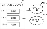
- the optical fiber sensing system includes an optical fiber network (in the figure, appropriately referred to as an optical fiber NW (Network)) 10A, 10B and an optical fiber sensing device 20.
- the optical fiber sensing device 20 includes receiving units 21A and 21B and a specific unit 22.
- the receiving units 21A and 21B are appropriately referred to as receiving units 21.
- FIG. 1 is an example on the premise that two optical fiber networks 10A and 10B are deployed, but the number of optical fiber networks 10 may be a plurality and is not limited to two.
- the optical fiber network 10A is composed of one or more sensing optical fibers 11A
- the optical fiber network 10B is composed of one or more sensing optical fibers 11B.
- the optical fiber networks 10A and 10B may be an existing optical fiber network or a newly established optical fiber network. In the following description, when it is not specified which of the sensing optical fibers 11A and 11B is used, the sensing optical fiber 11 is appropriately referred to as the sensing optical fiber 11.
- the receiving unit 21A receives an optical signal from the optical fiber network 10A.
- the receiving unit 21A sends pulsed light to the sensing optical fiber 11A constituting the optical fiber network 10A, and emits the backward scattered light generated by the pulsed light being transmitted through the sensing optical fiber 11A.
- Receive as a signal the receiving unit 21B receives an optical signal from the optical fiber network 10B.
- the monitoring targets monitored by the optical fiber sensing system according to the present embodiment are as follows, for example. ⁇ Conditions including deterioration of structures such as electric poles, bridges, tunnels, pipes, dams ⁇ Conditions including deterioration of railroads and roads ⁇ Conditions of railroads and roads ⁇ Behavior of people, vehicles, animals, etc.
- the optical fiber network 10A can detect sensing information including vibration, sound, temperature, and the like related to the monitored object.
- the optical fiber network 10B can detect sensing information including vibration, sound, temperature, etc. related to the monitored object, and the detected sensing information is superimposed on the optical signal transmitted by the sensing optical fiber 11B. Will be done.
- the sensing information may include at least one of vibration, sound, and temperature related to the monitored object.
- the specific unit 22 collects the sensing information superimposed on the optical signal received from the optical fiber network 10A by the receiving unit 21A, and collects the sensing information superimposed on the optical signal received by the receiving unit 21B from the optical fiber network 10B. To do. Then, the identification unit 22 identifies the monitoring target based on the sensing information superimposed on the optical signal received from the optical fiber network 10A and the sensing information superimposed on the optical signal received from the optical fiber network 10B. ..
- the specifying unit 22 can specify the position (distance from the optical fiber sensing device 20) on the sensing optical fibers 11A and 11B in which the sensing information is detected as follows. For example, when the optical signal received by the receiving unit 21A is backscattered light, the specific unit 22 determines the time when the receiving unit 21A sends the pulsed light to the sensing optical fiber 11A and the time when the receiving unit 21A sends the sensing optical fiber 11A. Based on the time difference from the time when the backscattered light is received from the light, the position on the sensing optical fiber 11A where the sensing information superimposed on the backscattered light is detected is specified. In the same manner, the identification unit 22 identifies the position on the sensing optical fiber 11B where the sensing information superimposed on the optical signal received from the optical fiber network 10B is detected.
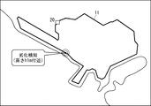
- the specific unit 22 has information for associating the position of the sensing optical fiber 11 with the actual geographical position.
- the specific unit 22 holds in advance a correspondence table in which the distance from the optical fiber sensing device 20 in the sensing optical fiber 11 and each region or point on the map are associated with each other. You may be.
- the specific unit 22 can determine in which area on the map the sensing information is detected, that is, in which area on the map the monitoring target specified above belongs. In this case, for example, when the position on the sensing optical fiber 11 detected by the sensing optical fiber 11 is 10 km, the specifying unit 22 may specify that it is the A region or the A point on the map. good.
- the position in the sensing optical fiber 11 is not limited to the distance from the optical fiber sensing device 20, and may be, for example, a distance from a specific point on the sensing optical fiber 11. Further, the actual geographical position is not limited to the area on the map, and for example, the area or the point may be managed by character information.
- the specific unit 22 may hold a correspondence table as shown in FIG. 2 for each of the sensing optical fibers 11A and 11B.
- the sensing information superimposed on the optical signal received by the receiving units 21A and 21B includes, for example, vibration information regarding the monitoring target.
- This vibration information is a unique dynamic fluctuation pattern in which patterns such as vibration intensity, vibration position, and frequency fluctuation transition differ depending on the monitoring target.
- the sensing information includes dynamic fluctuation patterns peculiar to the sound and temperature related to the monitoring target, and the monitoring target can be specified by these vibration patterns, acoustic patterns, temperature patterns, and the like. ..
- the specifying unit 22 identifies the monitoring target by analyzing the unique dynamic fluctuation pattern according to the monitoring target included in the sensing information superimposed on the optical signal received by the receiving units 21A and 21B. It becomes possible.
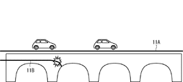
- sensing optical fibers 11A and 11B are laid on the structure.
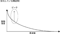
- the specific unit 22 collects sensing information from the optical signals received by the receiving units 21A and 21B from the sensing optical fibers 11A and 11B, and further, from the collected sensing information, has a structure as shown in FIGS. 3 and 4.
- Extract the vibration pattern generated by an object. 3 and 4 are vibration patterns after FFT (Fast Fourier Transform) of a vibration pattern in which the horizontal axis indicates time and the vertical axis indicates vibration intensity.
- FFT Fast Fourier Transform
- a peak of vibration intensity occurs.
- the frequency at which this peak occurs differs depending on the deterioration state of the structure.
- the frequency at which the intensity peak occurs is higher (or higher frequency side) than that of the vibration pattern of the normal structure (FIG. 3). It is shifting to the low frequency side). Therefore, the specific unit 22 can detect the deterioration of the structure based on the frequency at which the peak of the vibration intensity occurs.
- sensing optical fibers 11A and 11B are laid on the ground or the seabed.
- the identification unit 22 collects sensing information from the optical signals received by the receiving units 21A and 21B from the sensing optical fibers 11A and 11B, and further, from the collected sensing information, on the ground or the seabed as shown in FIG. Extract the generated vibration pattern.
- the horizontal axis represents time and the vertical axis represents vibration intensity.
- the vibration generated on the ground or the seabed is subsequently attenuated.
- this decay time becomes long. Therefore, the specific unit 22 can detect that the structural change or collapse of the ground may occur based on the damping time in the vibration pattern.
- the specific unit 22 may specify the monitoring target by using pattern matching.
- the specific unit 22 stores in advance a vibration pattern corresponding to the monitoring target in a storage unit (not shown) as a matching pattern for each monitoring target.
- a plurality of vibration patterns according to the deterioration level of the structure may be stored.
- the specific unit 22 extracts the vibration pattern from the optical signal
- the specific unit 22 compares the extracted vibration pattern with the matching pattern.
- the specifying unit 22 specifies the monitoring target corresponding to the matching pattern.
- the specific unit 22 may specify the monitoring target by using a learning model that specifies the monitoring target by a convolutional neural network (CNN).
- CNN convolutional neural network
- the specific unit 22 inputs a plurality of sets of teacher data indicating a monitoring target and a vibration pattern corresponding to the monitoring target, constructs a learning model in advance, and stores it in a storage unit (not shown) in advance. Keep it.
- a learning model may be constructed by inputting a plurality of sets of teacher data indicating the deterioration level of the structure and the vibration pattern at the deterioration level. ..
- the specific unit 22 extracts a vibration pattern from the optical signal, the specific unit 22 inputs the extracted vibration pattern to the learning model. As a result, the specific unit 22 obtains a monitoring target as an output result of the learning model.
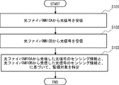
- the receiving unit 21A receives an optical signal from the optical fiber network 10A (step S101). Further, the receiving unit 21B receives an optical signal from the optical fiber network 10B (step S102). The order of step S101 and step S102 may be reversed.
- the specific unit 22 monitors the sensing information about the monitoring target included in the optical signal received by the receiving unit 21A from the optical fiber network 10A and the monitoring included in the optical signal received by the receiving unit 21B from the optical fiber network 10B.
- the monitoring target is specified based on the sensing information about the target (step S103).
- the receiving unit 21A receives the optical signal from the optical fiber network 10A
- the receiving unit 21B receives the optical signal from the optical fiber network 10B.
- the specific unit 22 senses the sensing information about the monitoring target included in the optical signal received by the receiving unit 21A from the optical fiber network 10A and the sensing information about the monitoring target included in the optical signal received by the receiving unit 21B from the optical fiber network 10B. Identify the monitoring target based on the information.
- the monitoring targets are monitored by both the two optical fiber networks 10A and 10B, instead of monitoring the monitoring targets individually by the optical fiber networks 10A and 10B.
- the monitoring targets are monitored by both the two optical fiber networks 10A and 10B, instead of monitoring the monitoring targets individually by the optical fiber networks 10A and 10B.
- the present embodiment is more embodied.
- the number of optical fiber networks 10 may be a plurality.
- the plurality of optical fiber networks 10 may be owned by different businesses.
- the optical fiber network 10A is an optical fiber network owned by the operator A (communication carrier)
- the optical fiber network 10B is an optical fiber network owned by the operator B (electric power company). It is 10B.
- the optical fiber network 10 is not limited to that owned by a communication carrier and an electric power company, but may be owned by a business operator in another industry such as a railway company or a road company. Further, the optical fiber network 10 may be owned by different business operators in different industries, or may be owned by different business operators in the same industry.
- the data to be monitored identified based on the sensing information detected by the plurality of optical fiber networks 10 can be obtained. It is possible to realize the service of providing to the service provider. Further, the optical fiber sensing device 20 can be realized as a platform in the case of realizing such a service.
- the specific unit 22 may provide the monitored data to the service providing destination, or may additionally provide a providing unit that provides the monitored data to the service providing destination.
- the service provider may be, for example, the national government, local governments, companies, individuals, etc., but is not particularly limited.
- the plurality of optical fiber networks 10 may be owned by different countries, local governments, and organizations (police, fire department, etc.).
- the plurality of optical fiber networks 10 may have different geographical locations from each other.
- the plurality of optical fiber networks 10 may be arranged in different prefectures from each other.
- the plurality of optical fiber networks 10 may be arranged on land and in the ocean, respectively.
- the plurality of optical fiber networks 10 may have different laying modes of the sensing optical fibers 11 from each other.
- a plurality of optical fiber networks 10 may have different substances, states (for example, buried in the ground, overhead wiring on utility poles, etc.) and heights on which the sensing optical fibers 11 are laid. good.
- the plurality of optical fiber networks 10 may be a mixture of a public optical fiber network 10 and a private optical fiber network 10.
- the public optical fiber network 10 is, for example, an optical fiber network in which a sensing optical fiber 11 is laid on utility poles, roads, railroad tracks, etc. as public infrastructure.
- the private optical fiber network 10 is, for example, an optical fiber network in which the sensing optical fiber 11 is laid as a private infrastructure in a building, a shopping mall, a home, a factory, or the like.
- the optical fiber network 10 in the private optical fiber network 10, there is a possibility that the optical fiber network 10 whose sensing information is highly confidential also exists. Therefore, it is preferable to set a policy regarding disclosure of sensing information for each private optical fiber network 10 and filter the sensing information according to the policy.
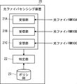
- optical fiber networks 10A to 10C owned by the businesses A to C are private optical fiber networks.
- the optical fiber sensing device 20 additionally includes a policy DB (DataBase) 23.
- the policy DB 23 is a database that stores a policy regarding disclosure of sensing information for each of the private optical fiber networks 10A to 10C.
- “all possible” indicates that the use of sensing information is permitted regardless of where the data to be monitored is provided.
- “Partially acceptable” indicates that the use of sensing information is permitted only when the data to be monitored is provided to some of the preset service providers.
- “Prohibited” indicates that the use of sensing information is permitted only when the data to be monitored is provided to itself. It should be noted that a mechanism for changing the policy or temporarily changing the policy in the event of a disaster may be additionally provided depending on the time of day.
- the specific unit 22 filters the sensing information superimposed on the optical signals received by the receiving units 21A to 21C according to the policy stored in the policy DB 23. Then, the identification unit 22 identifies the monitoring target based on the sensing information that is not excluded by the filtering. For example, it is assumed that the specific unit 22 filters the sensing information superimposed on the optical signal received by the receiving unit 21B. As a result, if the data provider of the monitoring target to be specified based on the sensing information is a preset service providing destination, the specifying unit 22 identifies and identifies the monitoring target based on the sensing information.
- the monitored data is provided to a preset service provider.
- the identification unit 22 does not specify the monitoring target or provide the monitoring target data. ..
- the receiving unit 21 collects the sensing information superimposed on the optical signal by receiving the optical signal from the sensing optical fiber 11 constituting the optical fiber network 10.
- the method of collecting sensing information is not limited to this.
- the receiving unit 21A may collect sensing information from the optical fiber network 10A via the optical fiber communication network 30.
- the receiving unit 21B may collect sensing information from the optical fiber network 10B via the optical fiber communication network 30.
- the identification unit 22 identifies the monitoring target based on the sensing information collected from the optical fiber network 10A and the sensing information collected from the optical fiber network 10B.
- the sensing cover range is expanded to a region in which the A region, which is the sensing cover range of the optical fiber network 10A, and the B region, which is the sensing cover range of the optical fiber network 10B, are combined. be able to.
- sensing information can be handed over between companies of the same affiliate that have different jurisdictions.
- the A region which is the sensing coverage range of the optical fiber network 10A
- the B region which is the sensing coverage range of the optical fiber network 10B.
- the A region and the B region may be separated from each other.
- the specific unit 22 estimates the monitoring target in the C region between the A region and the B region based on the specific result of the monitoring target in the A region and the specific result of the monitoring target in the B region. You may.
- the identification unit 22 specifies the position of the vehicle or the like in the A region based on the vibration pattern or the like included in the sensing information collected from the optical fiber network 10A, and further, based on the fluctuation of the specified position.
- the movement route of the vehicle etc. is specified.
- the identification unit 22 specifies the position and movement path of the vehicle or the like in the B region based on the vibration pattern or the like included in the sensing information collected from the optical fiber network 10B. Therefore, the specific unit 22 can estimate the movement route in the C region based on the position which is the exit of the movement route in the A region and the position which is the entrance of the movement route in the B region.
- the specifying unit 22 can specify the moving speed of the vehicle or the like based on the position of the vehicle or the like and the time when the vehicle or the like is in each of the A region and the B region. Therefore, for example, when the moving speed in the A region is 30 km and the moving speed in the B region is 40 km, the specific unit 22 can estimate that the vehicle or the like is accelerating in the C region.
- the identification unit 22 can specify the temperature in the A region based on the temperature pattern included in the sensing information collected from the optical fiber network 10A. Similarly, the identification unit 22 can specify the temperature in the B region based on the temperature pattern included in the sensing information collected from the optical fiber network 10B. Therefore, for example, when the temperature in the A region is 20 ° C. and the temperature in the B region is 30 ° C., the specific unit 22 can estimate that the temperature in the C region is about 25 ° C.
- the specifying unit 22 can specify the power failure occurrence position and the distribution of the power failure occurrence position in the A region based on the vibration pattern or the like included in the sensing information collected from the optical fiber network 10A.
- the specifying unit 22 can specify the power failure occurrence position and the distribution of the power failure occurrence position in the B region based on the vibration pattern or the like included in the sensing information collected from the optical fiber network 10B. Therefore, for example, the specific unit 22 can estimate the power failure occurrence position in the C region based on the distribution of the power failure occurrence position in the A region and the distribution of the power failure occurrence position in the B region.
- the receiving unit 21A receives an optical signal from the optical fiber network 10A whose sensing coverage range is the A region (step S201). Further, the receiving unit 21B receives an optical signal from the optical fiber network 10B whose sensing coverage range is the B region (step S202). The order of step S201 and step S202 may be reversed.
- the specifying unit 22 specifies the monitoring target in the A region based on the sensing information regarding the monitoring target included in the optical signal received from the optical fiber network 10A by the receiving unit 21A (step S203). Further, the specifying unit 22 identifies the monitoring target in the B region based on the sensing information regarding the monitoring target included in the optical signal received by the receiving unit 21B from the optical fiber network 10B (step S204). The order of step S203 and step S204 may be reversed.
- the specific unit 22 estimates the monitoring target in the C region between the A region and the B region based on the specific result of the monitoring target in the A region and the specific result of the monitoring target in the B region. (Step S205). ⁇ Identification of vibration source and sound source position>
- the specific unit 22 can specify the direction of the vibration source.
- the specific unit 22 cannot specify the position of the vibration source.
- the specific unit 22 specifies the position of the vibration source even if the vibration source is located at a location away from the sensing optical fiber 11. Can be done.
- two optical fiber networks 10 are deployed: an optical fiber network 10A composed of one sensing optical fiber 11A and an optical fiber network 10B composed of one sensing optical fiber 11B. It is assumed that it is.
- the sensing optical fiber 11A detects vibration at a plurality of detection points on the sensing optical fiber 11A.
- the specific unit 22 obtains the distribution of vibrations detected at each of the plurality of detection points (the intensity of the detected vibrations and the time when the vibrations are detected) based on the sensing information collected from the sensing optical fiber 11A. ..
- the identification unit 22 identifies the direction D1 of the vibration source based on the distribution of the vibrations detected at each of the plurality of detection points.
- the specific unit 22 obtains the vibration distribution (intensity and time) detected at each of the plurality of detection points based on the sensing information collected from the sensing optical fiber 11B, and is based on the obtained vibration distribution.
- the direction D2 of the vibration source is specified.
- the specifying unit 22 specifies the position where the direction D1 and the direction D2 intersect as the position of the vibration source.
- the specific unit 22 specified the position of the vibration source, but the position of the sound source can also be specified.
- the specifying unit 22 may specify the position of the sound source by using the distribution (intensity and time) of the sound detected at each of the plurality of detection points on the sensing optical fiber 11. good.
- ⁇ Deployment of multiple optical fiber networks in the same area By deploying a plurality of optical fiber networks 10 in the same area, it is possible to improve the sensing accuracy of the optical fiber sensing. For example, when only one optical fiber network 10 composed of one sensing optical fiber 11 is deployed, the sensing information that can be acquired by the specific unit 22 is the sensing information of the one-dimensional arrangement.
- the specific unit 22 can acquire the sensing information of the two-dimensional arrangement (for example, the two-dimensional arrangement with the sensing optical fiber 11A as the X-axis and the sensing optical fiber 11B as the Y-axis). Sensing information). As a result, the sensing accuracy can be improved.
- the specific unit 22 can acquire the sensing information of the three-dimensional arrangement. As a result, the sensing accuracy can be further improved.
- FIG. 17 shows an example of a method of laying three sensing optical fibers 11A to 11C constituting each of the three optical fiber networks 10A to 10C at different heights.
- the sensing optical fiber 11A is buried in the ground
- the sensing optical fiber 11B is overhead-wired to the utility pole
- the sensing optical fiber 11C is overhead-wired to the steel tower higher than the utility pole.
- the sensing optical fiber 11C can be realized as, for example, OPGW (optical ground wire).
- the specific unit 22 has information for associating the position of the sensing optical fiber 11 with the actual geographical position and height.
- the specific unit 22 includes the distance of the sensing optical fiber 11 from the optical fiber sensing device 20, the height at which the sensing optical fiber 11 is laid, and each region or region on the map.
- a correspondence table associated with the point may be held in advance.
- the specific unit 22 can not only determine in a plane which area on the map the specified monitoring target belongs to, but also determine which height the specified monitoring target belongs to. ..
- the specific unit 22 can grasp the monitoring target three-dimensionally. For example, if the monitoring target is the air volume, the specific unit 22 can specify the air volume three-dimensionally.
- the specific unit 22 may, for example, estimate the height of the monitoring target in a complex manner from the sensing information detected at a plurality of different heights. For example, the specific unit 22 monitors at a position of 5 meters from the sensing information detected at a height of 0 meters of the sensing optical fiber 11A and the sensing information detected at a height of 10 meters of the sensing optical fiber 11B. The height and direction of the target may be specified. Further, when performing complex estimation, the specific unit 22 may perform estimation based on, for example, vibration, sound intensity, distribution, etc. at each height position.
- the position in the sensing optical fiber 11 is not limited to the distance from the optical fiber sensing device 20, and may be, for example, a distance from a specific point on the sensing optical fiber 11. Further, the actual geographical position and height are not limited to the area on the map, and for example, the area or the point may be managed by character information.
- the specific unit 22 may hold a corresponding table as shown in FIG. 18 for each of the sensing optical fibers 11A to 11C.
- the type of sensing information that is easy to detect differs depending on the state in which the sensing optical fiber 11 is laid.
- the sensing optical fiber 11 buried in the ground can easily detect vibration, while the sensing optical fiber 11 laid in the air can easily detect sound.
- the sensing information that is easy to detect differs depending on the structure in which the sensing optical fiber 11 is laid. Therefore, the specifying unit 22 may combine different types of sensing information detected by the plurality of sensing optical fibers 11 laid in different states to specify the monitoring target in a complex manner. For example, when identifying the type of accident that occurred on the road, the identification unit 22 detected the vibration detected by the sensing optical fiber 11 buried in the ground and the sensing optical fiber 11 overhead-wired in the air. The type of accident may be identified based on the sound.
- the optical fiber network 10 is deployed in the ocean part and the land part in the same area, respectively, and the specific unit 22 monitors the fluctuation of the seawater temperature based on the temperature detected by the optical fiber network 10 deployed in the ocean part.
- the crustal movement may be monitored based on the vibration detected by the optical fiber network 10 deployed on the land portion.
- the specific unit 22 may specify the causal relationship between the fluctuation of the seawater temperature and the crustal movement.
- the specific unit 22 can specify where and how the crust fluctuates when the seawater temperature fluctuates.
- the identification unit 22 can identify the behavior of a person inside the building based on the sensing information collected from the optical fiber network 10 deployed inside the building such as a building. In addition, the identification unit 22 can identify the behavior of the vehicle on the road based on the sensing information collected from the optical fiber network 10 deployed on the road. Further, the identification unit 22 can specify a series of actions based on the actions of the person and the actions of the vehicle.
- specific examples of methods for identifying the behavior of a person and a vehicle will be described.
- the optical fiber network 10A is deployed inside the building 40 such as a building, and the optical fiber network 10B is deployed on the road.
- the identification unit 22 identifies the behavior of a person inside the building 40 based on a vibration pattern, an acoustic pattern, or the like included in the sensing information collected from the optical fiber network 10A. Further, the identification unit 22 specifies the behavior of the vehicle on the road based on the vibration pattern or the like included in the sensing information collected from the optical fiber network 10B.
- the specific unit 22 identifies the behavior, walking, etc. of a person inside the building 40 based on the vibration pattern or the like included in the sensing information collected from the optical fiber network 10A, and also collects from the optical fiber network 10A. It is possible to specify the content of conversation of a person inside the building 40 based on the acoustic pattern or the like included in the sensing information. As a result, it is assumed that the identification unit 22 identifies a plurality of persons who have taken suspicious actions based on the actions, walking methods, conversation contents, and the like of the persons inside the building 40.
- the identification unit 22 establishes a building based on a vibration pattern or the like included in the sensing information collected from the optical fiber network 10B at the timing when the plurality of persons cannot be detected.
- the specific unit 22 can determine that a plurality of persons inside the building 40 have boarded one vehicle. Further, thereafter, the specific unit 22 may track the vehicle based on the vibration pattern or the like included in the sensing information collected from the optical fiber network 10B.
- the identification unit 22 identifies the behavior of a person inside the buildings 40A to 40C based on the vibration pattern, the acoustic pattern, and the like included in the sensing information collected from the optical fiber networks 10A to 10C. Further, the identification unit 22 specifies the behavior of the vehicle on the road based on the vibration pattern or the like included in the sensing information collected from the optical fiber network 10D.
- the specific unit 22 identifies the person P who has taken a suspicious action based on the behavior of the person inside the building 40A, the way of walking, the content of the conversation, and the like.
- the specific unit 22 learns the pattern of the behavior, walking method, and conversation content of the person P, and stores the learned pattern in advance in a storage unit (not shown) as a matching pattern.
- the specific unit 22 determines the behavior, walking method, and conversation content pattern of the person in the buildings 40B and 40C based on the vibration pattern and the acoustic pattern included in the sensing information collected from the optical fiber networks 10B and 10C.
- the identified and identified pattern is compared with the matching pattern of the person P.
- the specific unit 22 indicates that the person P has moved to the buildings 40B and 40C. You can judge.
- the specific unit 22 may track the vehicle based on the vibration pattern or the like included in the sensing information collected from the optical fiber network 10D. ..
- the deployment of the optical fiber network 10D may be arbitrary.
- one of the two sensing optical fibers 11 constituting the two optical fiber networks 10 may be incorporated in the clothing, and the other may be incorporated in the bed.
- the specific unit 22 collects sensing from each of the sensing optical fiber 11 built in the clothing and the sensing optical fiber 11 built in the bed.
- the state of the person may be specified based on the vibration pattern, the acoustic pattern, the temperature pattern, and the like included in the information.
- the specific unit 22 can specify the state of a person based on patterns such as vibration of body organs, heart sounds, and body temperature.
- the sensing optical fiber 11 is also laid on the floor or the like of the room where the bed is installed, and the specific portion 22 also includes a vibration pattern or the like included in the sensing information collected from the sensing optical fiber 11 laid on the floor or the like. Further may be used to identify the state of the person.
- optical fiber network 10 deployed over a wide area and the partially deployed optical fiber network 10 are combined, and the specific unit 22 is a vibration included in the sensing information collected from each of these combined optical fiber networks 10.
- the monitoring target may be specified based on the pattern.
- the sensing optical fiber 11A constituting the optical fiber network 10A is laid over the entire bridge.
- the sensing optical fiber 11B constituting the optical fiber network 10B is partially laid in the deteriorated portion where cracks or the like have occurred.
- the identification unit 22 identifies the monitoring target based on the vibration pattern included in the sensing information collected from the sensing optical fibers 11A and 11B.
- the specific unit 22 identifies the traveling state of the vehicle or train traveling on the bridge based on the vibration pattern or the like included in the sensing information collected from the sensing optical fiber 11A, and determines the traveling state and the deteriorated portion. You may specify the causal relationship of.
- the specific unit 22 can specify under what driving conditions the degree of deterioration of the deteriorated portion deteriorates.
- the optical fiber network 10 composed of the sensing optical fiber 11 laid on the seabed and the optical fiber network 10 composed of the sensing optical fiber 11 laid on the ship are combined, and the specific unit 22 is a combination.
- the monitoring target may be specified based on the vibration pattern or the like included in the sensing information collected from each of these combinations of optical fiber networks 10.
- the specific unit 22 identifies the wave state based on the vibration pattern included in the sensing information collected from the sensing optical fiber 11 laid on the seabed, and from the sensing optical fiber 11 laid on the ship.
- the state of the luggage loaded on the ship may be specified based on the vibration pattern or the like included in the collected sensing information.
- the specific unit 22 may determine whether the factor is derived from waves or other factors (such as luggage loaded on the ship). good.
- the specifying unit 22 may notify an alert depending on the specified monitoring target.
- the specific unit 22 may display a GUI (Graphical User Interface) screen on a monitoring system that monitors the monitoring target or a display unit of a terminal owned by a person who monitors the monitoring target to perform the above notification. good.
- GUI Graphic User Interface
- the GUI screen for example, map information indicating the area monitored by the optical fiber network 10, information on the laid optical fiber 11 for sensing, information on the specified monitoring target, and the monitoring target are detected. Visually display information about the area or point.
- An example of this GUI screen is shown in FIG. FIG.
- the monitoring target displayed on the GUI screen is not limited to the deteriorated part, but includes various targets such as the state and traffic of vehicles and trains, and the behavior of people.
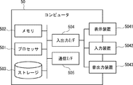
- the computer 50 includes a processor 501, a memory 502, a storage 503, an input / output interface (input / output I / F) 504, a communication interface (communication I / F) 505, and the like.
- the processor 501, the memory 502, the storage 503, the input / output interface 504, and the communication interface 505 are connected by a data transmission line for transmitting and receiving data to and from each other.
- the processor 501 is, for example, an arithmetic processing unit such as a CPU (Central Processing Unit) or a GPU (Graphics Processing Unit).
- the memory 502 is, for example, a memory such as a RAM (Random Access Memory) or a ROM (Read Only Memory).
- the storage 503 is, for example, a storage device such as an HDD (Hard Disk Drive), an SSD (Solid State Drive), or a memory card. Further, the storage 503 may be a memory such as a RAM or a ROM.
- the storage 503 stores a program that realizes the functions of the components (reception unit 21 and specific unit 22) included in the optical fiber sensing device 20. By executing each of these programs, the processor 501 realizes the functions of the components included in the optical fiber sensing device 20.
- the processor 501 may read these programs on the memory 502 and then execute the programs, or may execute the programs without reading them on the memory 502.
- the memory 502 and the storage 503 also play a role of storing information and data held by the components included in the optical fiber sensing device 20.
- Non-temporary computer-readable media include various types of tangible storage media.
- Examples of non-temporary computer-readable media include magnetic recording media (eg, flexible disks, magnetic tapes, hard disk drives), opto-magnetic recording media (eg, optomagnetic discs), CD-ROMs (Compact Disc-ROMs), CDs -R (CD-Recordable), CD-R / W (CD-ReWritable), semiconductor memory (for example, mask ROM, PROM (Programmable ROM), EPROM (Erasable PROM), flash ROM, RAM.
- the program also includes.
- the computer-readable medium can supply the program to the computer via a wired communication path such as an electric wire and an optical fiber, or a wireless communication path.
- the input / output interface 504 is connected to the display device 5041, the input device 5042, the sound output device 5043, and the like.
- the display device 5041 is a device that displays a screen corresponding to drawing data processed by the processor 501, such as an LCD (Liquid Crystal Display), a CRT (Cathode Ray Tube) display, and a monitor.
- the input device 5042 is a device that receives an operator's operation input, and is, for example, a keyboard, a mouse, a touch sensor, and the like.
- the display device 5041 and the input device 5042 may be integrated and realized as a touch panel.
- the sound output device 5043 is a device such as a speaker that acoustically outputs sound corresponding to acoustic data processed by the processor 501.
- the communication interface 505 sends and receives data to and from an external device.
- the communication interface 505 communicates with an external device via a wired communication path or a wireless communication path.
- Appendix 1 A first optical fiber network that detects the first sensing information about the monitored object, A second optical fiber network that detects the second sensing information about the monitored object, and A first receiving unit that receives a first optical signal from the first optical fiber network, and A second receiving unit that receives a second optical signal from the second optical fiber network, and A specific unit that identifies the monitoring target based on the first sensing information included in the first optical signal and the second sensing information included in the second optical signal.
- An optical fiber sensing system The first receiving unit receives the first optical signal from the first optical fiber network owned by the first operator, and receives the first optical signal.
- the second receiving unit receives the second optical signal from the second optical fiber network owned by the second operator.
- the optical fiber sensing system according to Appendix 1. (Appendix 3) Further provided with a database for preliminarily storing the first sensing information and the policy regarding the disclosure of the second sensing information.
- the specific unit filters the first sensing information and the second sensing information based on the policy, and is not excluded by the filtering among the first sensing information and the second sensing information. Identify the monitoring target based on the sensing information
- the first receiving unit receives the first optical signal from the first optical fiber network deployed in the first region, and receives the first optical signal.
- the second receiving unit receives the second optical signal from the second optical fiber network deployed in the second region.
- the optical fiber sensing system according to Appendix 1. (Appendix 5)
- the first region and the second region are separated from each other.
- the specific part is Based on the first sensing information included in the first optical signal, the monitoring target in the first region is specified.
- the monitoring target in the second region is specified.
- a third region between the first region and the second region is based on the identification result of the monitoring target in the first region and the identification result of the monitoring target in the second region. Estimate the monitoring target in the area,
- the specific unit identifies the monitoring target based on a unique dynamic fluctuation pattern according to the monitoring target included in the first sensing information and the second sensing information.
- the optical fiber sensing system according to any one of Appendix 1 to 5.
- the first sensing information and the second sensing information include at least one of vibration, sound, and temperature.
- the optical fiber sensing system according to any one of Appendix 1 to 6. This is an optical fiber sensing method using an optical fiber sensing system.
- Fiber optic sensing methods including. (Appendix 9)
- the first optical signal from the first optical fiber network owned by the first operator is received, and the first optical signal is received.
- the second optical signal from the second optical fiber network owned by the second operator is received.
- the first region and the second region are separated from each other.
- the monitoring target in the first region is specified.
- the monitoring target in the second region is specified.
- a third region between the first region and the second region is based on the identification result of the monitoring target in the first region and the identification result of the monitoring target in the second region.
- Estimate the monitoring target in the area The optical fiber sensing method according to Appendix 11.
- the monitoring target is specified based on the unique dynamic fluctuation pattern according to the monitoring target included in the first sensing information and the second sensing information.
- the optical fiber sensing method includes any one of Appendix 8 to 12.
- the first sensing information and the second sensing information include at least one of vibration, sound, and temperature.
- the optical fiber sensing method according to any one of Appendix 8 to 13.
- Appendix 15 A first receiver that receives a first optical signal from a first optical fiber network that detects first sensing information about a monitored object, and A second receiving unit that receives a second optical signal from the second optical fiber network that detects the second sensing information regarding the monitored object, and A specific unit that identifies the monitoring target based on the first sensing information included in the first optical signal and the second sensing information included in the second optical signal.
- An optical fiber sensing device An optical fiber sensing device.
- the first receiving unit receives the first optical signal from the first optical fiber network owned by the first operator, and receives the first optical signal.
- the second receiving unit receives the second optical signal from the second optical fiber network owned by the second operator.
- the optical fiber sensing device according to Appendix 15. (Appendix 17) Further provided with a database for preliminarily storing the first sensing information and the policy regarding the disclosure of the second sensing information.
- the specific unit filters the first sensing information and the second sensing information based on the policy, and is not excluded by the filtering among the first sensing information and the second sensing information. Identify the monitoring target based on the sensing information
- the optical fiber sensing device according to Appendix 15 or 16.
- the first receiving unit receives the first optical signal from the first optical fiber network deployed in the first region, and receives the first optical signal.
- the second receiving unit receives the second optical signal from the second optical fiber network deployed in the second region.
- the optical fiber sensing device according to Appendix 15.
- the first region and the second region are separated from each other. The specific part is Based on the first sensing information included in the first optical signal, the monitoring target in the first region is specified. Based on the second sensing information included in the second optical signal, the monitoring target in the second region is specified.
- a third region between the first region and the second region is based on the identification result of the monitoring target in the first region and the identification result of the monitoring target in the second region.
- the optical fiber sensing device according to Appendix 18.
- the specific unit identifies the monitoring target based on a unique dynamic fluctuation pattern according to the monitoring target included in the first sensing information and the second sensing information.
- the optical fiber sensing device according to any one of Appendix 15 to 19.
- the first sensing information and the second sensing information include at least one of vibration, sound, and temperature.
- the optical fiber sensing device according to any one of Appendix 15 to 20.
Landscapes
- Physics & Mathematics (AREA)
- General Physics & Mathematics (AREA)
- Electromagnetism (AREA)
- Engineering & Computer Science (AREA)
- Computer Networks & Wireless Communication (AREA)
- Signal Processing (AREA)
- Testing Or Calibration Of Command Recording Devices (AREA)
- Alarm Systems (AREA)
- Optical Transform (AREA)
- Emergency Alarm Devices (AREA)
Priority Applications (3)
| Application Number | Priority Date | Filing Date | Title |
|---|---|---|---|
| PCT/JP2019/039486 WO2021070222A1 (ja) | 2019-10-07 | 2019-10-07 | 光ファイバセンシングシステム、光ファイバセンシング方法、及び光ファイバセンシング装置 |
| US17/765,074 US12117336B2 (en) | 2019-10-07 | 2019-10-07 | Optical fiber sensing system, optical fiber sensing method, and optical fiber sensing apparatus |
| JP2021550955A JP7315014B2 (ja) | 2019-10-07 | 2019-10-07 | 光ファイバセンシングシステム、光ファイバセンシング方法、及び光ファイバセンシング装置 |
Applications Claiming Priority (1)
| Application Number | Priority Date | Filing Date | Title |
|---|---|---|---|
| PCT/JP2019/039486 WO2021070222A1 (ja) | 2019-10-07 | 2019-10-07 | 光ファイバセンシングシステム、光ファイバセンシング方法、及び光ファイバセンシング装置 |
Publications (1)
| Publication Number | Publication Date |
|---|---|
| WO2021070222A1 true WO2021070222A1 (ja) | 2021-04-15 |
Family
ID=75437036
Family Applications (1)
| Application Number | Title | Priority Date | Filing Date |
|---|---|---|---|
| PCT/JP2019/039486 Ceased WO2021070222A1 (ja) | 2019-10-07 | 2019-10-07 | 光ファイバセンシングシステム、光ファイバセンシング方法、及び光ファイバセンシング装置 |
Country Status (3)
| Country | Link |
|---|---|
| US (1) | US12117336B2 (https=) |
| JP (1) | JP7315014B2 (https=) |
| WO (1) | WO2021070222A1 (https=) |
Cited By (6)
| Publication number | Priority date | Publication date | Assignee | Title |
|---|---|---|---|---|
| JPWO2023021598A1 (https=) * | 2021-08-18 | 2023-02-23 | ||
| JPWO2023053214A1 (https=) * | 2021-09-28 | 2023-04-06 | ||
| JPWO2023073914A1 (https=) * | 2021-10-29 | 2023-05-04 | ||
| JPWO2023079732A1 (https=) * | 2021-11-08 | 2023-05-11 | ||
| JPWO2023209758A1 (https=) * | 2022-04-25 | 2023-11-02 | ||
| JP2024525374A (ja) * | 2021-07-22 | 2024-07-12 | エヌイーシー ラボラトリーズ アメリカ インク | 分散型光ファイバセンシングを用いた車両支援型埋設ケーブル位置特定 |
Families Citing this family (3)
| Publication number | Priority date | Publication date | Assignee | Title |
|---|---|---|---|---|
| US12467822B2 (en) * | 2020-08-31 | 2025-11-11 | Nec Corporation | Utility pole deterioration discrimination device and method |
| US11733070B2 (en) * | 2021-03-03 | 2023-08-22 | Nec Corporation | Street light operating status monitoring using distributed optical fiber sensing |
| US11676465B1 (en) * | 2021-08-04 | 2023-06-13 | The United States Of America As Represented By The Secretary Of The Navy | Fire detection and conflagration event monitoring and diagnosis system |
Citations (4)
| Publication number | Priority date | Publication date | Assignee | Title |
|---|---|---|---|---|
| JPH0620177A (ja) * | 1992-07-03 | 1994-01-28 | Mitsubishi Electric Corp | 繰り返し操作機構の異常検出装置 |
| JP2002269656A (ja) * | 2001-03-12 | 2002-09-20 | Foundation Of River & Basin Integrated Communications Japan | 河川情報提供システム |
| JP2003232043A (ja) * | 2002-02-06 | 2003-08-19 | Oki Electric Ind Co Ltd | 土砂異常検出装置、土砂異常検出システム、及び土砂異常検出方法 |
| US20050082467A1 (en) * | 2003-10-21 | 2005-04-21 | Guy Mossman | Optical fiber based sensor system suitable for monitoring remote aqueous infiltration |
-
2019
- 2019-10-07 US US17/765,074 patent/US12117336B2/en active Active
- 2019-10-07 WO PCT/JP2019/039486 patent/WO2021070222A1/ja not_active Ceased
- 2019-10-07 JP JP2021550955A patent/JP7315014B2/ja active Active
Patent Citations (4)
| Publication number | Priority date | Publication date | Assignee | Title |
|---|---|---|---|---|
| JPH0620177A (ja) * | 1992-07-03 | 1994-01-28 | Mitsubishi Electric Corp | 繰り返し操作機構の異常検出装置 |
| JP2002269656A (ja) * | 2001-03-12 | 2002-09-20 | Foundation Of River & Basin Integrated Communications Japan | 河川情報提供システム |
| JP2003232043A (ja) * | 2002-02-06 | 2003-08-19 | Oki Electric Ind Co Ltd | 土砂異常検出装置、土砂異常検出システム、及び土砂異常検出方法 |
| US20050082467A1 (en) * | 2003-10-21 | 2005-04-21 | Guy Mossman | Optical fiber based sensor system suitable for monitoring remote aqueous infiltration |
Cited By (12)
| Publication number | Priority date | Publication date | Assignee | Title |
|---|---|---|---|---|
| JP2024525374A (ja) * | 2021-07-22 | 2024-07-12 | エヌイーシー ラボラトリーズ アメリカ インク | 分散型光ファイバセンシングを用いた車両支援型埋設ケーブル位置特定 |
| JP7621526B2 (ja) | 2021-07-22 | 2025-01-24 | エヌイーシー ラボラトリーズ アメリカ インク | 分散型光ファイバセンシングを用いた車両支援型埋設ケーブル位置特定 |
| JPWO2023021598A1 (https=) * | 2021-08-18 | 2023-02-23 | ||
| WO2023021598A1 (ja) * | 2021-08-18 | 2023-02-23 | 日本電気株式会社 | 情報処理装置、情報処理方法、コンピュータ可読媒体、及び点検システム |
| JP7643556B2 (ja) | 2021-08-18 | 2025-03-11 | 日本電気株式会社 | 情報処理装置、情報処理方法、プログラム、及び点検システム |
| JPWO2023053214A1 (https=) * | 2021-09-28 | 2023-04-06 | ||
| JPWO2023073914A1 (https=) * | 2021-10-29 | 2023-05-04 | ||
| WO2023073914A1 (ja) * | 2021-10-29 | 2023-05-04 | 日本電気株式会社 | 光ファイバセンシングシステム、光ファイバセンシング機器、及び光ファイバセンシング方法 |
| JP7718501B2 (ja) | 2021-10-29 | 2025-08-05 | 日本電気株式会社 | 光ファイバセンシングシステム、光ファイバセンシング機器、及び光ファイバセンシング方法 |
| JPWO2023079732A1 (https=) * | 2021-11-08 | 2023-05-11 | ||
| JPWO2023209758A1 (https=) * | 2022-04-25 | 2023-11-02 | ||
| WO2023209758A1 (ja) * | 2022-04-25 | 2023-11-02 | 日本電気株式会社 | センシングシステム、センシング機器、及びセンシング方法 |
Also Published As
| Publication number | Publication date |
|---|---|
| US12117336B2 (en) | 2024-10-15 |
| JPWO2021070222A1 (https=) | 2021-04-15 |
| US20220397449A1 (en) | 2022-12-15 |
| JP7315014B2 (ja) | 2023-07-26 |
Similar Documents
| Publication | Publication Date | Title |
|---|---|---|
| WO2021070222A1 (ja) | 光ファイバセンシングシステム、光ファイバセンシング方法、及び光ファイバセンシング装置 | |
| JP7750518B2 (ja) | 分散音響センシングのための方法およびシステム | |
| US12000729B2 (en) | Perpendicular distance prediction of vibrations by distributed fiber optic sensing | |
| JP2024014948A (ja) | 道路監視システム、道路監視装置、道路監視方法、及びプログラム | |
| Duckworth et al. | OptaSense distributed acoustic and seismic sensing using COTS fiber optic cables for infrastructure protection and counter terrorism | |
| Xia et al. | Field trial of abnormal activity detection and threat level assessment with fiber optic sensing for telecom infrastructure protection | |
| Wang et al. | Employing fiber sensing and on-premise AI solutions for cable safety protection over telecom infrastructure | |
| Wang et al. | The impact of electrical hazards from overhead power lines on urban search and rescue operations during extreme flood events | |
| Zulfikar et al. | Istanbul natural gas network rapid response and risk mitigation system | |
| JP7311023B2 (ja) | 光ファイバセンシングシステム、光ファイバセンシング方法、及び光ファイバセンシング装置 | |
| JP7605222B2 (ja) | 光ファイバセンシングシステム、光ファイバセンシング方法、及び光ファイバセンシング装置 | |
| Korotaev et al. | Monitoring industrial facilities using principles of integration of fiber classifier and local sensor networks | |
| WO2021171593A1 (ja) | 検出システム、検出装置、及び検出方法 | |
| Lienhart et al. | Development and validation of a third party intrusion detection software based on DAS measurement data | |
| Tharanga et al. | Gps Based Safe Location Guiding Android Systems in Case of Tsunami | |
| Edwards et al. | 8 Earthquake early warning systems | |
| Kislov et al. | SEISMIC MONITORING AND PROTECTION OF EXTENDED OBJECTS | |
| Spizzichino et al. | THE SECOND WORLD LANDSLIDE FORUM |
Legal Events
| Date | Code | Title | Description |
|---|---|---|---|
| 121 | Ep: the epo has been informed by wipo that ep was designated in this application |
Ref document number: 19948742 Country of ref document: EP Kind code of ref document: A1 |
|
| ENP | Entry into the national phase |
Ref document number: 2021550955 Country of ref document: JP Kind code of ref document: A |
|
| NENP | Non-entry into the national phase |
Ref country code: DE |
|
| 122 | Ep: pct application non-entry in european phase |
Ref document number: 19948742 Country of ref document: EP Kind code of ref document: A1 |