WO2021065685A1 - Apparatus and method for producing polycrystalline silicon, and polycrystalline silicon - Google Patents
Apparatus and method for producing polycrystalline silicon, and polycrystalline silicon Download PDFInfo
- Publication number
- WO2021065685A1 WO2021065685A1 PCT/JP2020/036104 JP2020036104W WO2021065685A1 WO 2021065685 A1 WO2021065685 A1 WO 2021065685A1 JP 2020036104 W JP2020036104 W JP 2020036104W WO 2021065685 A1 WO2021065685 A1 WO 2021065685A1
- Authority
- WO
- WIPO (PCT)
- Prior art keywords
- filter
- polycrystalline silicon
- raw material
- material gas
- flow path
- Prior art date
Links
- 229910021420 polycrystalline silicon Inorganic materials 0.000 title claims abstract description 93
- 238000004519 manufacturing process Methods 0.000 title claims description 50
- 239000012535 impurity Substances 0.000 claims abstract description 54
- XUIMIQQOPSSXEZ-UHFFFAOYSA-N Silicon Chemical compound [Si] XUIMIQQOPSSXEZ-UHFFFAOYSA-N 0.000 claims abstract description 25
- 238000001556 precipitation Methods 0.000 claims abstract description 18
- 229910052710 silicon Inorganic materials 0.000 claims abstract description 16
- 239000010703 silicon Substances 0.000 claims abstract description 16
- 239000007789 gas Substances 0.000 claims description 95
- 239000002994 raw material Substances 0.000 claims description 81
- 239000002245 particle Substances 0.000 claims description 25
- 238000011144 upstream manufacturing Methods 0.000 claims description 19
- 238000001914 filtration Methods 0.000 claims description 17
- 239000010935 stainless steel Substances 0.000 claims description 12
- 229910001220 stainless steel Inorganic materials 0.000 claims description 12
- KOPOQZFJUQMUML-UHFFFAOYSA-N chlorosilane Chemical class Cl[SiH3] KOPOQZFJUQMUML-UHFFFAOYSA-N 0.000 claims description 9
- 239000005046 Chlorosilane Substances 0.000 claims description 8
- 239000001257 hydrogen Substances 0.000 claims description 6
- 229910052739 hydrogen Inorganic materials 0.000 claims description 6
- UFHFLCQGNIYNRP-UHFFFAOYSA-N Hydrogen Chemical compound [H][H] UFHFLCQGNIYNRP-UHFFFAOYSA-N 0.000 claims description 5
- 230000002093 peripheral effect Effects 0.000 claims description 4
- 230000001376 precipitating effect Effects 0.000 claims description 3
- 238000005259 measurement Methods 0.000 description 10
- 229910052751 metal Inorganic materials 0.000 description 10
- 239000002184 metal Substances 0.000 description 10
- PXHVJJICTQNCMI-UHFFFAOYSA-N nickel Substances [Ni] PXHVJJICTQNCMI-UHFFFAOYSA-N 0.000 description 9
- XEEYBQQBJWHFJM-UHFFFAOYSA-N iron Substances [Fe] XEEYBQQBJWHFJM-UHFFFAOYSA-N 0.000 description 7
- 239000011651 chromium Substances 0.000 description 6
- 238000009434 installation Methods 0.000 description 6
- 239000000463 material Substances 0.000 description 6
- VEXZGXHMUGYJMC-UHFFFAOYSA-M Chloride anion Chemical compound [Cl-] VEXZGXHMUGYJMC-UHFFFAOYSA-M 0.000 description 5
- 239000000470 constituent Substances 0.000 description 5
- 238000011109 contamination Methods 0.000 description 5
- 229910052742 iron Inorganic materials 0.000 description 5
- JEIPFZHSYJVQDO-UHFFFAOYSA-N iron(III) oxide Inorganic materials O=[Fe]O[Fe]=O JEIPFZHSYJVQDO-UHFFFAOYSA-N 0.000 description 5
- 238000000034 method Methods 0.000 description 5
- 229910052759 nickel Inorganic materials 0.000 description 5
- 229910052804 chromium Inorganic materials 0.000 description 4
- 230000000052 comparative effect Effects 0.000 description 4
- 239000010949 copper Substances 0.000 description 4
- 238000010586 diagram Methods 0.000 description 4
- 238000009826 distribution Methods 0.000 description 4
- 239000000428 dust Substances 0.000 description 4
- 239000011572 manganese Substances 0.000 description 4
- 239000010955 niobium Substances 0.000 description 4
- 239000000843 powder Substances 0.000 description 4
- 239000010936 titanium Substances 0.000 description 4
- ZDHXKXAHOVTTAH-UHFFFAOYSA-N trichlorosilane Chemical compound Cl[SiH](Cl)Cl ZDHXKXAHOVTTAH-UHFFFAOYSA-N 0.000 description 4
- 239000005052 trichlorosilane Substances 0.000 description 4
- 238000003466 welding Methods 0.000 description 4
- 229910052802 copper Inorganic materials 0.000 description 3
- 238000005260 corrosion Methods 0.000 description 3
- 230000007797 corrosion Effects 0.000 description 3
- 238000005520 cutting process Methods 0.000 description 3
- 229910052748 manganese Inorganic materials 0.000 description 3
- 229910052750 molybdenum Inorganic materials 0.000 description 3
- 229910052758 niobium Inorganic materials 0.000 description 3
- 230000001681 protective effect Effects 0.000 description 3
- 229910052719 titanium Inorganic materials 0.000 description 3
- ZAMOUSCENKQFHK-UHFFFAOYSA-N Chlorine atom Chemical compound [Cl] ZAMOUSCENKQFHK-UHFFFAOYSA-N 0.000 description 2
- GWEVSGVZZGPLCZ-UHFFFAOYSA-N Titan oxide Chemical compound O=[Ti]=O GWEVSGVZZGPLCZ-UHFFFAOYSA-N 0.000 description 2
- MCMNRKCIXSYSNV-UHFFFAOYSA-N Zirconium dioxide Chemical compound O=[Zr]=O MCMNRKCIXSYSNV-UHFFFAOYSA-N 0.000 description 2
- 230000000903 blocking effect Effects 0.000 description 2
- 239000000919 ceramic Substances 0.000 description 2
- 229910052801 chlorine Inorganic materials 0.000 description 2
- 239000000460 chlorine Substances 0.000 description 2
- 238000007599 discharging Methods 0.000 description 2
- 229910001385 heavy metal Inorganic materials 0.000 description 2
- 238000001095 inductively coupled plasma mass spectrometry Methods 0.000 description 2
- 230000000149 penetrating effect Effects 0.000 description 2
- 241000178343 Butea superba Species 0.000 description 1
- OKTJSMMVPCPJKN-UHFFFAOYSA-N Carbon Chemical compound [C] OKTJSMMVPCPJKN-UHFFFAOYSA-N 0.000 description 1
- VYZAMTAEIAYCRO-UHFFFAOYSA-N Chromium Chemical compound [Cr] VYZAMTAEIAYCRO-UHFFFAOYSA-N 0.000 description 1
- RYGMFSIKBFXOCR-UHFFFAOYSA-N Copper Chemical compound [Cu] RYGMFSIKBFXOCR-UHFFFAOYSA-N 0.000 description 1
- YCKRFDGAMUMZLT-UHFFFAOYSA-N Fluorine atom Chemical compound [F] YCKRFDGAMUMZLT-UHFFFAOYSA-N 0.000 description 1
- PWHULOQIROXLJO-UHFFFAOYSA-N Manganese Chemical compound [Mn] PWHULOQIROXLJO-UHFFFAOYSA-N 0.000 description 1
- ZOKXTWBITQBERF-UHFFFAOYSA-N Molybdenum Chemical compound [Mo] ZOKXTWBITQBERF-UHFFFAOYSA-N 0.000 description 1
- 229910052581 Si3N4 Inorganic materials 0.000 description 1
- RTAQQCXQSZGOHL-UHFFFAOYSA-N Titanium Chemical compound [Ti] RTAQQCXQSZGOHL-UHFFFAOYSA-N 0.000 description 1
- 239000000443 aerosol Substances 0.000 description 1
- 229910045601 alloy Inorganic materials 0.000 description 1
- 239000000956 alloy Substances 0.000 description 1
- PNEYBMLMFCGWSK-UHFFFAOYSA-N aluminium oxide Inorganic materials [O-2].[O-2].[O-2].[Al+3].[Al+3] PNEYBMLMFCGWSK-UHFFFAOYSA-N 0.000 description 1
- 238000005219 brazing Methods 0.000 description 1
- 229910052799 carbon Inorganic materials 0.000 description 1
- 238000006243 chemical reaction Methods 0.000 description 1
- 150000001805 chlorine compounds Chemical class 0.000 description 1
- SLLGVCUQYRMELA-UHFFFAOYSA-N chlorosilicon Chemical compound Cl[Si] SLLGVCUQYRMELA-UHFFFAOYSA-N 0.000 description 1
- PMHQVHHXPFUNSP-UHFFFAOYSA-M copper(1+);methylsulfanylmethane;bromide Chemical compound Br[Cu].CSC PMHQVHHXPFUNSP-UHFFFAOYSA-M 0.000 description 1
- 229910021419 crystalline silicon Inorganic materials 0.000 description 1
- 230000008021 deposition Effects 0.000 description 1
- MROCJMGDEKINLD-UHFFFAOYSA-N dichlorosilane Chemical compound Cl[SiH2]Cl MROCJMGDEKINLD-UHFFFAOYSA-N 0.000 description 1
- 239000006185 dispersion Substances 0.000 description 1
- 230000000694 effects Effects 0.000 description 1
- 239000011737 fluorine Substances 0.000 description 1
- 229910052731 fluorine Inorganic materials 0.000 description 1
- -1 for example Inorganic materials 0.000 description 1
- 239000012634 fragment Substances 0.000 description 1
- 230000004927 fusion Effects 0.000 description 1
- 230000005484 gravity Effects 0.000 description 1
- 229910000856 hastalloy Inorganic materials 0.000 description 1
- 238000010438 heat treatment Methods 0.000 description 1
- 150000002431 hydrogen Chemical class 0.000 description 1
- 229910001293 incoloy Inorganic materials 0.000 description 1
- 229910001026 inconel Inorganic materials 0.000 description 1
- 229910001055 inconels 600 Inorganic materials 0.000 description 1
- 239000011259 mixed solution Substances 0.000 description 1
- 238000012986 modification Methods 0.000 description 1
- 230000004048 modification Effects 0.000 description 1
- 239000011733 molybdenum Substances 0.000 description 1
- GUCVJGMIXFAOAE-UHFFFAOYSA-N niobium atom Chemical compound [Nb] GUCVJGMIXFAOAE-UHFFFAOYSA-N 0.000 description 1
- 238000010248 power generation Methods 0.000 description 1
- 239000010453 quartz Substances 0.000 description 1
- 239000004065 semiconductor Substances 0.000 description 1
- HBMJWWWQQXIZIP-UHFFFAOYSA-N silicon carbide Chemical compound [Si+]#[C-] HBMJWWWQQXIZIP-UHFFFAOYSA-N 0.000 description 1
- 229910010271 silicon carbide Inorganic materials 0.000 description 1
- VYPSYNLAJGMNEJ-UHFFFAOYSA-N silicon dioxide Inorganic materials O=[Si]=O VYPSYNLAJGMNEJ-UHFFFAOYSA-N 0.000 description 1
- HQVNEWCFYHHQES-UHFFFAOYSA-N silicon nitride Chemical compound N12[Si]34N5[Si]62N3[Si]51N64 HQVNEWCFYHHQES-UHFFFAOYSA-N 0.000 description 1
- FDNAPBUWERUEDA-UHFFFAOYSA-N silicon tetrachloride Chemical compound Cl[Si](Cl)(Cl)Cl FDNAPBUWERUEDA-UHFFFAOYSA-N 0.000 description 1
- 239000000243 solution Substances 0.000 description 1
- 235000012431 wafers Nutrition 0.000 description 1
- XLYOFNOQVPJJNP-UHFFFAOYSA-N water Substances O XLYOFNOQVPJJNP-UHFFFAOYSA-N 0.000 description 1
Images


Classifications
-
- C—CHEMISTRY; METALLURGY
- C01—INORGANIC CHEMISTRY
- C01B—NON-METALLIC ELEMENTS; COMPOUNDS THEREOF; METALLOIDS OR COMPOUNDS THEREOF NOT COVERED BY SUBCLASS C01C
- C01B33/00—Silicon; Compounds thereof
- C01B33/02—Silicon
- C01B33/021—Preparation
- C01B33/027—Preparation by decomposition or reduction of gaseous or vaporised silicon compounds other than silica or silica-containing material
- C01B33/035—Preparation by decomposition or reduction of gaseous or vaporised silicon compounds other than silica or silica-containing material by decomposition or reduction of gaseous or vaporised silicon compounds in the presence of heated filaments of silicon, carbon or a refractory metal, e.g. tantalum or tungsten, or in the presence of heated silicon rods on which the formed silicon is deposited, a silicon rod being obtained, e.g. Siemens process
-
- B—PERFORMING OPERATIONS; TRANSPORTING
- B01—PHYSICAL OR CHEMICAL PROCESSES OR APPARATUS IN GENERAL
- B01D—SEPARATION
- B01D46/00—Filters or filtering processes specially modified for separating dispersed particles from gases or vapours
- B01D46/24—Particle separators, e.g. dust precipitators, using rigid hollow filter bodies
- B01D46/2403—Particle separators, e.g. dust precipitators, using rigid hollow filter bodies characterised by the physical shape or structure of the filtering element
- B01D46/2411—Filter cartridges
-
- C—CHEMISTRY; METALLURGY
- C01—INORGANIC CHEMISTRY
- C01B—NON-METALLIC ELEMENTS; COMPOUNDS THEREOF; METALLOIDS OR COMPOUNDS THEREOF NOT COVERED BY SUBCLASS C01C
- C01B33/00—Silicon; Compounds thereof
- C01B33/02—Silicon
-
- C—CHEMISTRY; METALLURGY
- C23—COATING METALLIC MATERIAL; COATING MATERIAL WITH METALLIC MATERIAL; CHEMICAL SURFACE TREATMENT; DIFFUSION TREATMENT OF METALLIC MATERIAL; COATING BY VACUUM EVAPORATION, BY SPUTTERING, BY ION IMPLANTATION OR BY CHEMICAL VAPOUR DEPOSITION, IN GENERAL; INHIBITING CORROSION OF METALLIC MATERIAL OR INCRUSTATION IN GENERAL
- C23C—COATING METALLIC MATERIAL; COATING MATERIAL WITH METALLIC MATERIAL; SURFACE TREATMENT OF METALLIC MATERIAL BY DIFFUSION INTO THE SURFACE, BY CHEMICAL CONVERSION OR SUBSTITUTION; COATING BY VACUUM EVAPORATION, BY SPUTTERING, BY ION IMPLANTATION OR BY CHEMICAL VAPOUR DEPOSITION, IN GENERAL
- C23C16/00—Chemical coating by decomposition of gaseous compounds, without leaving reaction products of surface material in the coating, i.e. chemical vapour deposition [CVD] processes
- C23C16/22—Chemical coating by decomposition of gaseous compounds, without leaving reaction products of surface material in the coating, i.e. chemical vapour deposition [CVD] processes characterised by the deposition of inorganic material, other than metallic material
- C23C16/24—Deposition of silicon only
-
- C—CHEMISTRY; METALLURGY
- C23—COATING METALLIC MATERIAL; COATING MATERIAL WITH METALLIC MATERIAL; CHEMICAL SURFACE TREATMENT; DIFFUSION TREATMENT OF METALLIC MATERIAL; COATING BY VACUUM EVAPORATION, BY SPUTTERING, BY ION IMPLANTATION OR BY CHEMICAL VAPOUR DEPOSITION, IN GENERAL; INHIBITING CORROSION OF METALLIC MATERIAL OR INCRUSTATION IN GENERAL
- C23C—COATING METALLIC MATERIAL; COATING MATERIAL WITH METALLIC MATERIAL; SURFACE TREATMENT OF METALLIC MATERIAL BY DIFFUSION INTO THE SURFACE, BY CHEMICAL CONVERSION OR SUBSTITUTION; COATING BY VACUUM EVAPORATION, BY SPUTTERING, BY ION IMPLANTATION OR BY CHEMICAL VAPOUR DEPOSITION, IN GENERAL
- C23C16/00—Chemical coating by decomposition of gaseous compounds, without leaving reaction products of surface material in the coating, i.e. chemical vapour deposition [CVD] processes
- C23C16/44—Chemical coating by decomposition of gaseous compounds, without leaving reaction products of surface material in the coating, i.e. chemical vapour deposition [CVD] processes characterised by the method of coating
- C23C16/4401—Means for minimising impurities, e.g. dust, moisture or residual gas, in the reaction chamber
- C23C16/4402—Reduction of impurities in the source gas
-
- C—CHEMISTRY; METALLURGY
- C23—COATING METALLIC MATERIAL; COATING MATERIAL WITH METALLIC MATERIAL; CHEMICAL SURFACE TREATMENT; DIFFUSION TREATMENT OF METALLIC MATERIAL; COATING BY VACUUM EVAPORATION, BY SPUTTERING, BY ION IMPLANTATION OR BY CHEMICAL VAPOUR DEPOSITION, IN GENERAL; INHIBITING CORROSION OF METALLIC MATERIAL OR INCRUSTATION IN GENERAL
- C23C—COATING METALLIC MATERIAL; COATING MATERIAL WITH METALLIC MATERIAL; SURFACE TREATMENT OF METALLIC MATERIAL BY DIFFUSION INTO THE SURFACE, BY CHEMICAL CONVERSION OR SUBSTITUTION; COATING BY VACUUM EVAPORATION, BY SPUTTERING, BY ION IMPLANTATION OR BY CHEMICAL VAPOUR DEPOSITION, IN GENERAL
- C23C16/00—Chemical coating by decomposition of gaseous compounds, without leaving reaction products of surface material in the coating, i.e. chemical vapour deposition [CVD] processes
- C23C16/44—Chemical coating by decomposition of gaseous compounds, without leaving reaction products of surface material in the coating, i.e. chemical vapour deposition [CVD] processes characterised by the method of coating
- C23C16/455—Chemical coating by decomposition of gaseous compounds, without leaving reaction products of surface material in the coating, i.e. chemical vapour deposition [CVD] processes characterised by the method of coating characterised by the method used for introducing gases into reaction chamber or for modifying gas flows in reaction chamber
- C23C16/45563—Gas nozzles
-
- C—CHEMISTRY; METALLURGY
- C23—COATING METALLIC MATERIAL; COATING MATERIAL WITH METALLIC MATERIAL; CHEMICAL SURFACE TREATMENT; DIFFUSION TREATMENT OF METALLIC MATERIAL; COATING BY VACUUM EVAPORATION, BY SPUTTERING, BY ION IMPLANTATION OR BY CHEMICAL VAPOUR DEPOSITION, IN GENERAL; INHIBITING CORROSION OF METALLIC MATERIAL OR INCRUSTATION IN GENERAL
- C23C—COATING METALLIC MATERIAL; COATING MATERIAL WITH METALLIC MATERIAL; SURFACE TREATMENT OF METALLIC MATERIAL BY DIFFUSION INTO THE SURFACE, BY CHEMICAL CONVERSION OR SUBSTITUTION; COATING BY VACUUM EVAPORATION, BY SPUTTERING, BY ION IMPLANTATION OR BY CHEMICAL VAPOUR DEPOSITION, IN GENERAL
- C23C16/00—Chemical coating by decomposition of gaseous compounds, without leaving reaction products of surface material in the coating, i.e. chemical vapour deposition [CVD] processes
- C23C16/44—Chemical coating by decomposition of gaseous compounds, without leaving reaction products of surface material in the coating, i.e. chemical vapour deposition [CVD] processes characterised by the method of coating
- C23C16/46—Chemical coating by decomposition of gaseous compounds, without leaving reaction products of surface material in the coating, i.e. chemical vapour deposition [CVD] processes characterised by the method of coating characterised by the method used for heating the substrate
-
- B—PERFORMING OPERATIONS; TRANSPORTING
- B01—PHYSICAL OR CHEMICAL PROCESSES OR APPARATUS IN GENERAL
- B01D—SEPARATION
- B01D46/00—Filters or filtering processes specially modified for separating dispersed particles from gases or vapours
- B01D46/24—Particle separators, e.g. dust precipitators, using rigid hollow filter bodies
- B01D46/2403—Particle separators, e.g. dust precipitators, using rigid hollow filter bodies characterised by the physical shape or structure of the filtering element
Definitions
- the present invention relates to a polycrystalline silicon manufacturing apparatus, a manufacturing method, and a polycrystalline silicon.
- the Siemens method is known as one of the methods for producing polycrystalline silicon used as a raw material for semiconductors or wafers for photovoltaic power generation.
- the silicon core wire arranged inside the bell jar type reactor is heated to the silicon precipitation temperature by energization.
- silicon precipitation temperature for example, by supplying trichlorosilane (SiHCl 3 ) and hydrogen (H 2 ) into the reactor, polycrystalline silicon is precipitated on the silicon core wire to obtain rod-shaped polycrystalline silicon.
- Patent Document 1 discloses a reactor including a feed gas system and an off-gas system, wherein the feed gas system and / or the off-gas system has an opening or a mesh and includes at least one protective element. Has been done.
- the protective element is provided to prevent fragments of polycrystalline silicon from falling into the feed gas opening and the off-gas opening and blocking the gas conduit or gas distributor.
- impurities derived from materials used for piping and the like may adhere to the supply flow path for supplying the raw material gas into the reactor.
- the impurities are scattered in the reactor and adhere to the polycrystalline silicon being precipitated, so that the impurity concentration of the produced polycrystalline silicon may increase.
- One aspect of the present invention is to reduce the impurity concentration of the polycrystalline silicon produced.
- the polycrystalline silicon manufacturing apparatus is formed in the reactor together with the inflow of the raw material gas and the reactor containing the raw material gas for silicon precipitation.
- a filter for removing impurities is provided.
- the method for producing polycrystalline silicon according to one aspect of the present invention is mixed with the raw material gas by a filter provided in a supply flow path for supplying the raw material gas into a reactor containing the raw material gas for silicon precipitation. It includes an impurity removing step of removing the impurities, and a silicon precipitation step of precipitating polycrystalline silicon by supplying the raw material gas from which the impurities have been removed in the impurity removing step into the reactor.
- the impurity concentration of the produced polycrystalline silicon can be reduced.
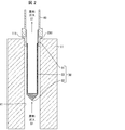
- FIG. 1 is a schematic view showing a manufacturing apparatus 1 for polycrystalline silicon S1 according to the first embodiment of the present invention.
- the manufacturing apparatus 1 for polycrystalline silicon S1 includes a reactor 10, a supply pipe 20 (pipe), a filter 30, a supply nozzle 40, an electrode 50, and a discharge pipe 60. ..
- the manufacturing apparatus 1 does not have to include the supply nozzle 40.
- the reactor 10 is composed of a bottom portion 11 on which polycrystalline silicon S1 is arranged and a bell jar type lid portion 12 that is detachably connected to the bottom portion 11.
- the reactor 10 accommodates the raw material gas G1 for silicon precipitation in a state where the lid portion 12 is connected to the bottom portion 11.
- the raw material gas G1 is a mixed gas of chlorosilanes and hydrogen.
- the bottom portion 11 is formed with an inflow port 111 for the raw material gas G1 to flow into the reactor 10 and an discharge port 112 for discharging the exhaust gas HG after the reaction in the reactor 10.
- a through hole H1 penetrating the bottom portion 11 extends from the inflow port 111.
- a through hole H2 penetrating the bottom portion 11 extends from the discharge port 112.
- two inlets 111 are formed at the bottom 11 and one outlet 112 is formed at the bottom 11, but the number of inlets 111 and 112s formed at the bottom 11 is particularly limited. Not done.
- the supply pipe 20 is composed of a first pipe 21 and a second pipe 22.
- One end of the first pipe 21 is connected to a supply unit (not shown) for supplying the raw material gas G1, and the other end is connected to the second pipe 22.
- the raw material gas G1 can be evenly supplied to each of the inflow ports 111.
- the number of the second pipes 22 is two, but since it is the same as the number of the inflow ports 111, it may be appropriately changed according to the number of the inflow ports 111.
- the second pipe 22 connects the first pipe 21 and the bottom portion 11.
- the second pipe 22 extends between the connecting portion of the first pipe 21 and the second pipe 22 and the end of the through hole H1 opposite to the inflow port 111.
- the second pipe 22 may extend between the connection portion of the first pipe 21 and the second pipe 22 and the inflow port 111.
- the supply pipe 20 is made of, for example, stainless steel.
- Stainless steel is an alloy containing at least one of the constituent elements such as Fe, Ni, Cr, Mn, Cu, Ti, Mo and Nb. Since the supply pipe 20 is corroded by the raw material gas G1, impurities of the constituent elements of stainless steel are mixed in the raw material gas G1. The impurities include oxides and chlorides of the constituent elements of stainless steel.
- the supply pipe 20 is made of stainless steel, for example, at least one of the heavy metal elements Fe, Ni, Cr, Mn, Cu, Ti, Mo and Nb reacts due to the constituent elements of the stainless steel. It is possible to prevent the vessel from entering the vessel 10.
- the supply flow path for supplying the raw material gas G1 into the reactor 10 is formed by the supply pipe 20, the inflow port 111, and the supply nozzle 40. That is, the supply flow path includes the inflow port 111, and the supply pipe 20 forms the supply flow path.
- the supply flow path also includes the inflow port E1 of the supply nozzle 40, that is, the tip of the supply nozzle 40.
- the supply nozzle 40 is a nozzle that protrudes into the reactor 10 from the inflow port 111.
- the supply nozzle 40 is provided at the bottom 11 in order to allow the raw material gas G1 flowing in from the inflow port 111 to reach the upper part in the reactor 10 and uniformly grow the polycrystalline silicon S1. Further, the supply nozzle 40 is for preventing the raw material gas G1 from directly hitting the vicinity of the electrode 50. The supply nozzle 40 can prevent the polycrystalline silicon S1 from being easily broken.
- the supply nozzle 40 is preferably made of a material having high corrosion resistance to the raw material gas G1, for example, made of carbon.
- the supply nozzle 40 has the shape of a nozzle, it may have a shape other than the nozzle, and may be, for example, an orifice plate provided at the inflow port 111.
- the electrode 50 is a member for supplying electric power to a silicon core wire (not shown) electrically connected to the electrode 50, and is a member for energizing and heating the silicon core wire. At least a pair of electrodes 50 are provided on the bottom portion 11. The number of electrodes 50 is determined according to the number of silicon core wires installed inside the reactor 10.
- the discharge pipe 60 is a pipe for discharging the exhaust gas HG generated in the silicon precipitation step described later to the outside of the reactor 10.
- the discharge pipe 60 extends between the outside of the reactor 10 and the end of the through hole H2 opposite to the discharge port 112.
- the discharge pipe 60 may extend between the outside of the reactor 10 and the discharge port 112.
- the filter 30 is a member provided in the supply flow path and for removing impurities mixed in the raw material gas G1. That is, the filter 30 is provided in any of the supply pipe 20, the inflow port 111, the supply nozzle 40, and the inflow port E1. In order to reduce the amount of impurities entering the reactor 10 as much as possible, the filter 30 is preferably provided in the vicinity of the reactor 10 in the supply flow path or inside the reactor 10, for example, the supply flow path. It is preferable that the inlet 111 is provided in the above.
- FIG. 2 is a cross-sectional view showing the configuration of the filter 30 included in the polycrystalline silicon S1 manufacturing apparatus 1 shown in FIG.
- the filter 30 has a cylindrical shape and includes a first end 31, a second end 32, and a filter surface 33.
- the filter 30 has a shape in which the first end 31 is opened, the second end 32 on the side opposite to the first end 31 is closed, and the filter surface 33 extends between the first end 31 and the second end 32. Is.
- the filter 30 is preferably made of a material having high corrosion resistance to the raw material gas G1, for example, stainless steel containing 10% or more of Ni, corrosion resistant materials (Hastelloy, Inconel 600, Inconel 800, Incoloy 800H, etc.) and the like. It can be composed of ceramics (alumina, titania, zirconia, quartz, silicon carbide, silicon nitride, aluminum nitride, etc.). Considering economic efficiency, the filter 30 is preferably made of stainless steel containing 10% or more of Ni, and more preferably made of SUS316L.
- the first end 31 is arranged on the downstream side of the supply flow path, and the second end 32 is arranged on the upstream side of the supply flow path.
- the structure of the filter 30 is such that the first end 31 is arranged on the side opposite to the second end 32.
- the first end 31 of the filter 30 is fixed to the connecting member CN1 attached to the inflow port 111.
- a filter 30 is fixed to one end of the connecting member CN1, and a supply nozzle 40 is attached to the other end of the connecting member CN1. Further, by removing the connecting member CN1 from the inflow port 111, the filter 30 fixed to the connecting member CN1 can be easily cleaned.
- the outer peripheral side of the first end 31 is fixed to the inner wall of the supply flow path so that the first end 31 and the second end 32 are lined up along the inner wall of the supply flow path. That is, the outer peripheral side of the first end 31 is fixed to at least one inner wall of the supply pipe 20, the through hole H1 of the bottom portion 11, and the supply nozzle 40.
- the surface area of the filter 30 can be increased, the pressure loss of the raw material gas G1 due to the installation of the filter 30 can be reduced. Further, the raw material gas G1 can be stably supplied without clogging the filter 30 until the deposition of the polycrystalline silicon S1 is completed. Therefore, polycrystalline silicon S1 can be efficiently produced.
- the filter surface 33 may be made of, for example, a mesh or a sintered body of fine powder such as metal or ceramic. Further, the filter surface 33 may be composed of a structure in which a mesh and a sintered body are overlapped. In this case, it is preferable that the mesh is arranged on the outside and the sintered body is arranged on the inside.
- impurities mixed in the raw material gas G1 for silicon precipitation can be removed by the filter 30, and the raw material gas G1 from which the impurities have been removed can be supplied into the reactor 10.
- Polycrystalline silicon S1 can be produced. Therefore, the impurity concentration of the produced polycrystalline silicon S1 can be reduced.
- the filter 30 removes impurities mixed in the raw material gas G1 (impurity removing step).
- the impurity removing step is preferably performed immediately before the raw material gas G1 is supplied into the reactor 10. As a result, the amount of impurities that enter the reactor 10 can be reduced as much as possible.
- polycrystalline silicon S1 is precipitated by supplying the raw material gas G1 from which impurities have been removed in the impurity removing step into the reactor 10 (silicon precipitation step). Further, in the method for producing polycrystalline silicon S1, the raw material gas G1 is preferably a mixed gas of chlorosilanes and hydrogen.
- the raw material gas G1 contains chlorosilanes having chlorine in the molecule and also having corrosiveness, the material of the supply pipe 20 is eroded, and rust and chloride are generated on the surface, resulting in rust. Even if a part of chloride or chloride is mixed in the raw material gas G1, it can be prevented from entering the reactor 10.
- the chlorosilanes are, for example, tetrachlorosilane, trichlorosilane, dichlorosilane, monochlorosilane, and the like, and in general, trichlorosilane is preferably used as the chlorosilanes.
- the polycrystalline silicon S1 produced by the above-mentioned method for producing polycrystalline silicon S1 is also included in the technical scope of the present invention.
- FIG. 3 is a diagram showing an example of the configuration of the filter 30A included in the polycrystalline silicon S1 manufacturing apparatus according to the second embodiment of the present invention.
- the view shown by FA is a front view of the filter 30A
- the view shown by FB is a side view of the filter 30A.
- the manufacturing apparatus according to the second embodiment is different from the manufacturing apparatus 1 according to the first embodiment in that the filter 30 is changed to the filter 30A.
- a part of the filter 30A has a tapered shape that tapers from the first end 31A connected to the connecting member CN1 toward the second end 32A opposite to the first end 31A. .. That is, a part of the filter 30A has a tapered shape that tapers from the inflow port 111 toward the upstream of the supply flow path.
- the filter 30A may have a tapered shape that tapers from the inflow port 111 toward the upstream of the supply flow path.
- the manufacturing apparatus according to the second embodiment may include, instead of the filter 30A, a filter having a tapered shape in which at least a part thereof tapers from the upstream of the supply flow path toward the inflow port 111.
- the filter 30A even if the raw material gas G1 collides with the filter 30A, the flow of the raw material gas G1 is reduced from being obstructed by the filter 30A, and the pressure loss of the raw material gas G1 due to the installation of the filter 30A is reduced. be able to.
- the filter having a tapered shape in which at least a part of the filter tapers from the upstream of the supply flow path toward the inflow port 111 Even in this case, since the space through which the raw material gas G1 passes becomes wider toward the inflow port 111 from the upstream of the supply flow path, the raw material gas G1 can be smoothly passed. Therefore, the pressure loss of the raw material gas G1 due to the installation of the filter can be reduced.
- a cutout surface 35 is formed in the filter 30A by cutting out a part of the surface 34 of the filter 30A.
- a plate-shaped filter 36 is attached to the cutout surface 35 to form the plate-shaped filter 36 as a filter surface.
- the cutout surface 35 and the plate-shaped filter 36 may extend between the first end 31A and the second end 32A.
- the cutout surface 35 and the plate-shaped filter 36 have a shape in which the width increases in the direction orthogonal to the stretching direction of the filter 30A from the first end 31A to the second end 32A. Further, as shown in FIG. 3, the cutout surface 35 and the plate-shaped filter 36 are formed at two positions symmetrically with respect to the center line L1 of the filter 30A along the stretching direction of the filter 30A, respectively.
- the plate-shaped filter 36 can be attached, for example, by welding or welding, and specifically, by fusion welding, pressure welding, or brazing.
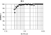
- FIG. 4 is a diagram showing the filtration accuracy of the filter 30A shown in FIG.
- the size of impurities mixed in the raw material gas G1 supplied into the reactor 10 is about 1 ⁇ m or more. Therefore, the filtration accuracy of the filter 30A is preferably 95% or more with respect to the particles having a particle size of 1 ⁇ m or more. That is, the filter 30A preferably removes 95% of the particles having a particle size of 1 ⁇ m or more.
- the filtration accuracy of the filter 30A is 90% or more with respect to the particles having a particle size of 0.3 ⁇ m or more.
- the filter 30A preferably removes 90% or more of the particles having a particle size of 0.3 ⁇ m or more. According to the above configuration, impurities mixed in the raw material gas G1 can be removed with high efficiency.
- filtration accuracy means the filtration accuracy measured by the following method.
- AC dust an air cleaner test dust (hereinafter referred to as AC dust) is supplied to the upstream side of the filter 30A by using a dry dispersion type aerosol generator (RBG1000, manufactured by PALAS).
- the syringe diameter of the syringe for supplying the compressed powder is set to 7 mm, and the supply speed is set to 5 mm / h.
- the supply speed corresponds to a supply speed of 190 mg / h assuming that the bulk specific gravity of the compressed powder is 1 g / cc.
- diluted air is supplied to the upstream side of the filter 30A at a flow rate of 40 L / min.
- the particle size distribution upstream of the filter 30A is measured for 20 seconds, and then the particle size distribution downstream of the filter 30A is measured for 20 seconds.
- the filtration accuracy at the particle size is obtained by dividing the average number of particles downstream of the filter 30A [number of particles / cm 3 ] by the average number of particles upstream of the filter 30A [number of particles / cm 3]. Is calculated.
- the measurement of the particle size distribution upstream of the filter 30A and the measurement of the particle size distribution downstream of the filter 30A are repeated three times, and the average value of the filtration accuracy calculated by each of these three measurements is used as the final filtration of the filter 30A. Accuracy. As a result of measuring the filtration accuracy of the filter 30A in this way, the filtration accuracy shown in FIG. 4 was obtained.
- the horizontal axis is the particle size [ ⁇ m]
- the vertical axis is the filtration accuracy [%].
- a filter 30A is used as the filter, and a plate-shaped filter 36 composed of a sintered body is used. Further, in the measurement result, a filter 30A made of SUS316L is used, and the dimensions of the filter 30A are as shown below.
- the length M1 along the stretching direction of the filter 30A at the opening of the filter 30A is 300 mm, and the length along the stretching direction of the filter 30A at the tip T1 of the filter 30A.
- M2 is 50 mm.
- the thickness of the plate filter 36 is 1 mm.
- the filter 30A is manufactured by cutting out a part of a pipe, the outer diameter of the pipe is 27.2 mm, and the inner diameter of the pipe is 23.9 mm.
- FIG. 5 is a diagram showing an example of the configuration of a filter included in the polycrystalline silicon S1 manufacturing apparatus according to the third embodiment of the present invention.
- the view shown by FC is a front view of the filter 30B
- the view shown by FD is a perspective view of the filter 30C.
- the manufacturing apparatus according to the third embodiment is different from the manufacturing apparatus 1 according to the first embodiment in that the filter 30 is changed to the filter 30B or the filter 30C.
- the filter 30B is composed of a cylindrical portion 41, a central portion 42, and a conical portion 43. From the downstream side of the supply flow path, the cylindrical portion 41, the central portion 42, and the conical portion 43 are formed in this order.
- the cylindrical portion 41 has a cylindrical shape and is connected to the connecting member CN1.
- the central portion 42 has a shape in which the apex is cut from the cone.
- the conical portion 43 has a conical shape.
- the central portion 42 and the conical portion 43 are formed so that the inclination angle of the central portion 42 is smaller than the inclination angle of the conical portion 43.
- a part of the filter 30B may have the tapered shape due to the central portion 42 and the conical portion 43. Due to the configuration of the filter 30B, the flow of the raw material gas G1 is less likely to be obstructed by the filter 30B.
- the entire filter included in the manufacturing apparatus according to the third embodiment may have a conical shape.
- the filter 30C has the shape of a triangular prism.
- the quadrangular surface 44 having the smallest area among the three quadrangular surfaces related to the triangular prism of the filter 30C is connected to the connecting member CN1.
- the filter 30C may have a shape in which the surface 44 is changed to a polygon other than a quadrangle.
- the filter 30C may have the tapered shape due to the triangular prism.
- the filter included in the manufacturing apparatus according to the third embodiment may have a polygonal pyramid shape such as a triangular pyramid or a quadrangular pyramid. In this case, the bottom of the polygonal pyramid is connected to the connecting member CN1, and the top is arranged on the upstream side of the supply flow path.
- FIG. 6 is a diagram showing an example of the configuration of a filter included in the polycrystalline silicon S1 manufacturing apparatus according to the fourth embodiment of the present invention.
- the view shown by FE is a front view of the filter 30D
- the view shown by FF is a side view of the filter 30D.
- the manufacturing apparatus according to the fourth embodiment is different from the manufacturing apparatus 1 according to the first embodiment in that the filter 30 is changed to the filter 30D.
- the filter 30D has a disk shape.
- An opening 48 is formed in the center of the flat surface 47 on the front side of the filter 30D, and a plate-shaped filter 49 is attached to the opening 48 so as to close the opening 48.
- the filter 30D has a side surface 51.
- the side surface 51 is connected to the connecting member CN1.
- the filter 30D is preferably stretched in a direction orthogonal to the flow direction of the raw material gas G1 flowing through the supply flow path.
- the shape of the filter 30D is not limited to the disk shape, and for example, the plane orthogonal to the flow direction of the raw material gas G1 may be a quadrangle or a triangle other than a circle. Further, the filter 30D may be extended in a direction inclined from a direction orthogonal to the flow direction of the raw material gas G1 flowing through the supply flow path.
- the apparatus for producing polycrystalline silicon is a supply flow path including a reactor accommodating a raw material gas for silicon precipitation and an inflow port formed in the reactor as the raw material gas flows in. It is provided with a pipe for forming the supply flow path for supplying the raw material gas into the reactor, and a filter provided in the supply flow path and for removing impurities mixed in the raw material gas. ..
- impurities mixed in the raw material gas for silicon precipitation can be removed by a filter, so that the polycrystalline silicon can be produced by supplying the raw material gas from which the impurities have been removed into the reactor. Therefore, the impurity concentration of the produced polycrystalline silicon can be reduced.
- the filter may be provided at the inflow port in the supply flow path. According to the above configuration, the amount of impurities entering the reactor can be reduced as much as possible by providing the filter at the inflow port.
- the raw material gas may be a mixed gas of chlorosilanes and hydrogen. According to the above configuration, although the raw material gas contains chlorosilanes having chlorine in the molecule and also having corrosiveness, the piping material is eroded and rust and chloride are generated on the surface, resulting in rust and rust. Even if a part of chloride is mixed with the raw material gas, it can be prevented from entering the reactor.
- the piping forming the supply flow path may be made of stainless steel. According to the above configuration, due to the constituent elements of stainless steel, for example, heavy metal elements Fe (iron), Ni (nickel), Cr (chromium), Mn (manganese), Cu (copper), Ti (titanium). ), Mo (molybdenum) and Nb (niobium) can be prevented from entering the reactor.
- the filtration accuracy of the filter may be 90% or more with respect to particles having a particle size of 0.3 ⁇ m or more. According to the above configuration, impurities mixed in the raw material gas can be removed with high efficiency.
- At least a part of the filter may have a tapered shape that tapers from the inflow port toward the upstream of the supply flow path, or a tapered shape that tapers from the upstream of the supply flow path toward the inflow port. ..
- the filter has a shape in which the first end is open, the second end opposite to the first end is closed, and the filter surface extends between the first end and the second end.
- the outer peripheral side of the first end may be fixed to the inner wall of the supply flow path so that the first end and the second end are lined up along the inner wall of the supply flow path.
- the surface area of the filter can be increased, so that the pressure loss of the raw material gas due to the installation of the filter can be reduced.
- the raw material gas can be stably supplied without blocking the filter until the completion of the precipitation of polycrystalline silicon. Therefore, polycrystalline silicon can be efficiently produced.
- the method for producing polycrystalline silicon according to one aspect of the present invention is mixed with the raw material gas by a filter provided in a supply flow path for supplying the raw material gas into a reactor containing the raw material gas for silicon precipitation. It includes an impurity removing step of removing the impurities, and a silicon precipitation step of precipitating polycrystalline silicon by supplying the raw material gas from which the impurities have been removed in the impurity removing step into the reactor.
- the impurity removing step may be performed immediately before the raw material gas is supplied into the reactor. According to the above configuration, the amount of impurities entering the reactor can be reduced as much as possible by performing the impurity removing step immediately before the raw material gas is supplied into the reactor.
- the polycrystalline silicon according to one aspect of the present invention may be produced by the method for producing polycrystalline silicon.
- a polycrystalline silicon rod was manufactured using the polycrystalline silicon S1 manufacturing apparatus having the structure of the second embodiment of the present invention. That is, in the manufacturing apparatus 1 shown in FIG. 1, a polycrystalline silicon rod was manufactured by using a filter 30 replaced with a filter 10A.
- the reactor 10 is capable of erecting 10 polycrystalline silicon rods (5 pairs of inverted U-shaped polycrystalline silicon S1), and a polycrystalline silicon S1 manufacturing apparatus is used. The production of the crystalline silicon rod was carried out as described below.
- Each silicon core wire having an inverted U shape having a height of 2000 mm installed at the bottom 11 of the reactor 10 was energized, and each silicon core wire was heated so that the temperature of each silicon core wire became about 1000 ° C.
- a fully purified mixed gas of trichlorosilane and hydrogen is supplied into the reactor 10 by flowing through the supply pipe 20, and each of the silicon core wires (one side of the square cross section is 8 mm).
- Polycrystalline silicon was precipitated in the water. Precipitation of polycrystalline silicon continued until the diameter of the polycrystalline silicon rod grew to 120 mm.
- the supply pipe 20 is made of stainless steel, and the manufacture of the polycrystalline silicon rod under the same conditions is repeated 100 times before the implementation of this embodiment. It was.
- the filter the filter 30A shown in FIG. 3 made of SUS316L was used. The filtration accuracy of the filter 30A was such that 90% or more of the particles having a particle size of 0.3 ⁇ m or more could be removed.
- the mounting position of the filter 30A with respect to the supply pipe 20 was the mounting position shown in FIG.
- a cylinder having a diameter of 10 mm and a length of 120 mm was hollowed out from the polycrystalline silicon rod in the horizontal direction orthogonal to the longitudinal direction in the vicinity of a position in the middle of the polycrystalline silicon rod in the longitudinal direction.
- the columnar body extends in the horizontal direction.
- a polycrystalline silicon cylinder obtained by hollowing out the polycrystalline silicon rod.
- the radial direction is assumed to be the radial direction of the cross section of the polycrystalline silicon rod.
- a cylinder having a diameter of 10 mm and a height of 4 mm is obtained by vertically cutting the cylinder at a position 2 mm in the front-rear direction in the radial direction from a position 4 mm inside in the radial direction from one end of the cylinder (the outer skin surface of the polycrystalline silicon rod).
- a sample for measuring the shape of the outer skin was obtained.
- the cylinder is vertically arranged at a position 2 mm in the front-rear direction in the radial direction. It was cut to obtain a measurement sample in the middle part. Further, in the cylinder, the cylinder is vertically cut at the center position of the cross section of the polycrystalline silicon rod and the position outside the center position by 4 mm in the radial direction to obtain a sample for measuring the core wire portion. It was.
- the metal content of each of these measurement samples was analyzed. Specifically, the amount of each metal element of Cr, Fe, and Ni in the solution obtained by dissolving the target measurement sample in a fluorine mixed solution is analyzed by inductively coupled plasma mass spectrometry (ICP-MS). did. The average value of the analytical values of 10 polycrystalline silicon rods for each measurement sample was determined as the metal concentration in the site of each polycrystalline silicon rod. As a result of this example, the metal concentration in each part is shown in Table 1 below.
- the polycrystalline silicon rod was manufactured in the same manner as in the above embodiment except that the filter 30A was not provided in the supply pipe 20.
- the state of contamination by metal impurities was confirmed by the same method as in the above-mentioned example.
- the metal concentration in each site is shown in Table 2 below.
- the polycrystalline silicon rod of the above-mentioned example has Cr in all of the core wire portion, the intermediate portion and the outer skin portion as compared with the polycrystalline silicon rod of the present comparative example. , Fe, and Ni metal concentrations were significantly reduced. From this result, it was possible to confirm the significant effect of suppressing the contamination of metal impurities by providing the filter 30A in the supply pipe 20.
- the present invention can be used for producing polycrystalline silicon.
Landscapes
- Chemical & Material Sciences (AREA)
- Organic Chemistry (AREA)
- Inorganic Chemistry (AREA)
- Chemical Kinetics & Catalysis (AREA)
- General Chemical & Material Sciences (AREA)
- Engineering & Computer Science (AREA)
- Materials Engineering (AREA)
- Mechanical Engineering (AREA)
- Metallurgy (AREA)
- Physics & Mathematics (AREA)
- Geometry (AREA)
- Silicon Compounds (AREA)
Abstract
The present invention reduces the concentration of impurities in a polycrystalline silicon to be produced. An apparatus (1) for producing a polycrystalline silicon (S1) is provided with: a reactor (10) which contains a raw gas (G1) for silicon precipitation; a supply pipe (20) which forms a supply flow path in which the raw gas (G1) flows and which includes an inflow port (111) formed in the reactor (10), wherein the supply flow path is for supplying the raw gas (G1) into the reactor (10); and a filter which is provided in the supply flow path and removes impurities mixed in the raw gas (G1).
Description
本発明は、多結晶シリコンの製造装置、製造方法および多結晶シリコンに関する。
The present invention relates to a polycrystalline silicon manufacturing apparatus, a manufacturing method, and a polycrystalline silicon.
従来、半導体または太陽光発電用ウエハの原料として使用される多結晶シリコンを製造する方法の一つとして、例えばシーメンス法が知られている。シーメンス法では、まず、ベルジャー型の反応器内部に配置されたシリコン芯線を通電によってシリコンの析出温度に加熱する。この状態で、例えば、トリクロロシラン(SiHCl3)および水素(H2)を反応器内に供給することにより、シリコン芯線上に多結晶シリコンを析出させ、ロッド状の多結晶シリコンを得る。
Conventionally, for example, the Siemens method is known as one of the methods for producing polycrystalline silicon used as a raw material for semiconductors or wafers for photovoltaic power generation. In the Siemens method, first, the silicon core wire arranged inside the bell jar type reactor is heated to the silicon precipitation temperature by energization. In this state, for example, by supplying trichlorosilane (SiHCl 3 ) and hydrogen (H 2 ) into the reactor, polycrystalline silicon is precipitated on the silicon core wire to obtain rod-shaped polycrystalline silicon.
特許文献1には、フィードガスシステムおよびオフガスシステムを備える反応器であって、フィードガスシステムおよび/またはオフガスシステムが、開口部またはメッシュを有し、少なくとも1個の保護要素を備える反応器が開示されている。前記保護要素は、多結晶シリコンの破片がフィードガス用開口部およびオフガス用開口部に落下し、気体導管または気体分配装置を閉塞することを防ぐために設けられている。
Patent Document 1 discloses a reactor including a feed gas system and an off-gas system, wherein the feed gas system and / or the off-gas system has an opening or a mesh and includes at least one protective element. Has been done. The protective element is provided to prevent fragments of polycrystalline silicon from falling into the feed gas opening and the off-gas opening and blocking the gas conduit or gas distributor.
しかしながら、原料ガスを反応器内に供給するための供給流路には、配管等に使用される材料由来の不純物が付着することがある。原料ガスが反応器へ供給されると、前記不純物が反応器内に飛散して、析出中の多結晶シリコンに付着することにより、製造される多結晶シリコンの不純物濃度が上昇することがある。
However, impurities derived from materials used for piping and the like may adhere to the supply flow path for supplying the raw material gas into the reactor. When the raw material gas is supplied to the reactor, the impurities are scattered in the reactor and adhere to the polycrystalline silicon being precipitated, so that the impurity concentration of the produced polycrystalline silicon may increase.
不純物の大きさは、非常に小さいので、特許文献1に開示された保護要素によって、不純物による汚染を防ぐことは困難である。したがって、特許文献1に開示された従来技術では、製造される多結晶シリコンの不純物濃度が上昇するという問題がある。本発明の一態様は、製造される多結晶シリコンの不純物濃度を低下させることを目的とする。
Since the size of impurities is very small, it is difficult to prevent contamination by impurities by the protective element disclosed in Patent Document 1. Therefore, the prior art disclosed in Patent Document 1 has a problem that the impurity concentration of the produced polycrystalline silicon increases. One aspect of the present invention is to reduce the impurity concentration of the polycrystalline silicon produced.
前記の課題を解決するために、本発明の一態様に係る多結晶シリコンの製造装置は、シリコン析出用の原料ガスを収容する反応器と、前記原料ガスが流入するとともに前記反応器に形成される流入口を含む供給流路であって、前記原料ガスを前記反応器内に供給するための前記供給流路を形成する配管と、前記供給流路に設けられるとともに、前記原料ガスに混入した不純物を除去するフィルタと、を備える。
In order to solve the above-mentioned problems, the polycrystalline silicon manufacturing apparatus according to one aspect of the present invention is formed in the reactor together with the inflow of the raw material gas and the reactor containing the raw material gas for silicon precipitation. A supply flow path including an inflow port, which is provided in a pipe forming the supply flow path for supplying the raw material gas into the reactor, and is provided in the supply flow path and mixed with the raw material gas. A filter for removing impurities is provided.
本発明の一態様に係る多結晶シリコンの製造方法は、シリコン析出用の原料ガスを収容する反応器内に前記原料ガスを供給するための供給流路に設けられるフィルタによって、前記原料ガスに混入した不純物を除去する不純物除去工程と、前記不純物除去工程で前記不純物が除去された前記原料ガスを前記反応器内に供給することにより、多結晶シリコンを析出させるシリコン析出工程と、を含む。
The method for producing polycrystalline silicon according to one aspect of the present invention is mixed with the raw material gas by a filter provided in a supply flow path for supplying the raw material gas into a reactor containing the raw material gas for silicon precipitation. It includes an impurity removing step of removing the impurities, and a silicon precipitation step of precipitating polycrystalline silicon by supplying the raw material gas from which the impurities have been removed in the impurity removing step into the reactor.
本発明の一態様によれば、製造される多結晶シリコンの不純物濃度を低下させることができる。
According to one aspect of the present invention, the impurity concentration of the produced polycrystalline silicon can be reduced.
〔実施形態1〕
<多結晶シリコンS1の製造装置1の構成>
図1は、本発明の実施形態1に係る多結晶シリコンS1の製造装置1を示す概略図である。図1に示すように、多結晶シリコンS1の製造装置1は、反応器10と、供給配管20(配管)と、フィルタ30と、供給ノズル40と、電極50と、排出配管60と、を備える。なお、製造装置1は、供給ノズル40を備えていなくてもよい。 [Embodiment 1]
<Structure of Manufacturing Device 1 for Polycrystalline Silicon S1>
FIG. 1 is a schematic view showing a manufacturing apparatus 1 for polycrystalline silicon S1 according to the first embodiment of the present invention. As shown in FIG. 1, the manufacturing apparatus 1 for polycrystalline silicon S1 includes areactor 10, a supply pipe 20 (pipe), a filter 30, a supply nozzle 40, an electrode 50, and a discharge pipe 60. .. The manufacturing apparatus 1 does not have to include the supply nozzle 40.
<多結晶シリコンS1の製造装置1の構成>
図1は、本発明の実施形態1に係る多結晶シリコンS1の製造装置1を示す概略図である。図1に示すように、多結晶シリコンS1の製造装置1は、反応器10と、供給配管20(配管)と、フィルタ30と、供給ノズル40と、電極50と、排出配管60と、を備える。なお、製造装置1は、供給ノズル40を備えていなくてもよい。 [Embodiment 1]
<Structure of Manufacturing Device 1 for Polycrystalline Silicon S1>
FIG. 1 is a schematic view showing a manufacturing apparatus 1 for polycrystalline silicon S1 according to the first embodiment of the present invention. As shown in FIG. 1, the manufacturing apparatus 1 for polycrystalline silicon S1 includes a
反応器10は、多結晶シリコンS1が配置される底部11と、底部11に対して着脱自在に連結されるベルジャー型の蓋部12と、から構成されている。反応器10は、底部11に対して蓋部12が連結された状態でシリコン析出用の原料ガスG1を収容する。原料ガスG1は、クロロシラン類と水素との混合ガスである。
The reactor 10 is composed of a bottom portion 11 on which polycrystalline silicon S1 is arranged and a bell jar type lid portion 12 that is detachably connected to the bottom portion 11. The reactor 10 accommodates the raw material gas G1 for silicon precipitation in a state where the lid portion 12 is connected to the bottom portion 11. The raw material gas G1 is a mixed gas of chlorosilanes and hydrogen.
底部11には、反応器10内に原料ガスG1が流入するための流入口111と、反応器10内の反応後の排ガスHGを排出するための排出口112と、が形成されている。流入口111から、底部11を貫通する貫通孔H1が延伸している。排出口112から、底部11を貫通する貫通孔H2が延伸している。図1では、流入口111が底部11に2つ形成され、排出口112が底部11に1つ形成されているが、底部11に形成される流入口111および排出口112の数は、特に限定されない。
The bottom portion 11 is formed with an inflow port 111 for the raw material gas G1 to flow into the reactor 10 and an discharge port 112 for discharging the exhaust gas HG after the reaction in the reactor 10. A through hole H1 penetrating the bottom portion 11 extends from the inflow port 111. A through hole H2 penetrating the bottom portion 11 extends from the discharge port 112. In FIG. 1, two inlets 111 are formed at the bottom 11 and one outlet 112 is formed at the bottom 11, but the number of inlets 111 and 112s formed at the bottom 11 is particularly limited. Not done.
供給配管20は、第1配管21と、第2配管22と、から構成されている。第1配管21は、一端が原料ガスG1を供給する供給部(図示せず)に接続され、他端が第2配管22に接続されている。流入口111のそれぞれには、原料ガスG1を均等に供給することができる。図1では、第2配管22の数は2つであるが、流入口111の数と同一であるため、流入口111の数に対応して適宜変更されてもよい。
The supply pipe 20 is composed of a first pipe 21 and a second pipe 22. One end of the first pipe 21 is connected to a supply unit (not shown) for supplying the raw material gas G1, and the other end is connected to the second pipe 22. The raw material gas G1 can be evenly supplied to each of the inflow ports 111. In FIG. 1, the number of the second pipes 22 is two, but since it is the same as the number of the inflow ports 111, it may be appropriately changed according to the number of the inflow ports 111.
第2配管22は、第1配管21と底部11とを接続している。第2配管22は、第1配管21および第2配管22の接続部分と、貫通孔H1における流入口111とは反対側の端と、の間を延伸している。なお、第2配管22は、第1配管21および第2配管22の接続部分と、流入口111と、の間を延伸していてもよい。
The second pipe 22 connects the first pipe 21 and the bottom portion 11. The second pipe 22 extends between the connecting portion of the first pipe 21 and the second pipe 22 and the end of the through hole H1 opposite to the inflow port 111. The second pipe 22 may extend between the connection portion of the first pipe 21 and the second pipe 22 and the inflow port 111.
供給配管20は、例えば、ステンレス鋼製である。ステンレス鋼は、例えば、Fe、Ni、Cr、Mn、Cu、Ti、MoおよびNb等の少なくともいずれかの構成元素を含む合金である。供給配管20は、原料ガスG1によって腐食されることにより、原料ガスG1に、ステンレス鋼の構成元素の不純物が混入する。前記不純物は、ステンレス鋼の構成元素の酸化物および塩化物を含む。
The supply pipe 20 is made of, for example, stainless steel. Stainless steel is an alloy containing at least one of the constituent elements such as Fe, Ni, Cr, Mn, Cu, Ti, Mo and Nb. Since the supply pipe 20 is corroded by the raw material gas G1, impurities of the constituent elements of stainless steel are mixed in the raw material gas G1. The impurities include oxides and chlorides of the constituent elements of stainless steel.
供給配管20がステンレス鋼製であることにより、ステンレス鋼の構成元素に起因して、例えば、重金属元素であるFe、Ni、Cr、Mn、Cu、Ti、MoおよびNbのうち少なくとも1つが、反応器10内に侵入することを防止できる。
Since the supply pipe 20 is made of stainless steel, for example, at least one of the heavy metal elements Fe, Ni, Cr, Mn, Cu, Ti, Mo and Nb reacts due to the constituent elements of the stainless steel. It is possible to prevent the vessel from entering the vessel 10.
原料ガスG1を反応器10内に供給するための供給流路は、供給配管20と、流入口111と、供給ノズル40と、から形成される。つまり、前記供給流路は、流入口111を含み、供給配管20は、前記供給流路を形成する。また、前記供給流路は、供給ノズル40の流入口E1、つまり、供給ノズル40の先端も含む。
The supply flow path for supplying the raw material gas G1 into the reactor 10 is formed by the supply pipe 20, the inflow port 111, and the supply nozzle 40. That is, the supply flow path includes the inflow port 111, and the supply pipe 20 forms the supply flow path. The supply flow path also includes the inflow port E1 of the supply nozzle 40, that is, the tip of the supply nozzle 40.
供給ノズル40は、流入口111から反応器10内に突出するノズルである。供給ノズル40は、流入口111から流入する原料ガスG1を反応器10内の上部に到達させ、多結晶シリコンS1を均一に成長させるために、底部11に設けられている。また、供給ノズル40は、原料ガスG1が電極50の近傍に直接当たらないようにするためのものである。供給ノズル40により、多結晶シリコンS1が折れやすくなることを防止できる。
The supply nozzle 40 is a nozzle that protrudes into the reactor 10 from the inflow port 111. The supply nozzle 40 is provided at the bottom 11 in order to allow the raw material gas G1 flowing in from the inflow port 111 to reach the upper part in the reactor 10 and uniformly grow the polycrystalline silicon S1. Further, the supply nozzle 40 is for preventing the raw material gas G1 from directly hitting the vicinity of the electrode 50. The supply nozzle 40 can prevent the polycrystalline silicon S1 from being easily broken.
供給ノズル40は、原料ガスG1に対する耐腐食性が高い材料から構成されることが好ましく、例えばカーボン製である。供給ノズル40は、ノズルの形状を有しているが、ノズル以外の形状を有していてもよく、例えば、流入口111に設けられたオリフィス板であってもよい。
The supply nozzle 40 is preferably made of a material having high corrosion resistance to the raw material gas G1, for example, made of carbon. Although the supply nozzle 40 has the shape of a nozzle, it may have a shape other than the nozzle, and may be, for example, an orifice plate provided at the inflow port 111.
電極50は、電極50に電気的に接続されたシリコン芯線(図示せず)に電力を供給するための部材であり、シリコン芯線を通電して加熱するための部材である。電極50は、底部11に少なくとも一対設けられている。電極50の数は、反応器10の内部に設置されるシリコン芯線の数に対応して決定される。
The electrode 50 is a member for supplying electric power to a silicon core wire (not shown) electrically connected to the electrode 50, and is a member for energizing and heating the silicon core wire. At least a pair of electrodes 50 are provided on the bottom portion 11. The number of electrodes 50 is determined according to the number of silicon core wires installed inside the reactor 10.
排出配管60は、後述するシリコン析出工程にて生成される排ガスHGを、反応器10の外部へ排出するための配管である。排出配管60は、反応器10の外部と、貫通孔H2における排出口112とは反対側の端と、の間を延伸している。なお、排出配管60は、反応器10の外部と、排出口112と、の間を延伸していてもよい。
The discharge pipe 60 is a pipe for discharging the exhaust gas HG generated in the silicon precipitation step described later to the outside of the reactor 10. The discharge pipe 60 extends between the outside of the reactor 10 and the end of the through hole H2 opposite to the discharge port 112. The discharge pipe 60 may extend between the outside of the reactor 10 and the discharge port 112.
<フィルタ30の構成>
フィルタ30は、前記供給流路に設けられるとともに、原料ガスG1に混入した不純物を除去する部材である。つまり、フィルタ30は、供給配管20、流入口111、供給ノズル40および流入口E1のいずれかに設けられる。反応器10内に侵入する不純物の量を極力低減するために、フィルタ30は、前記供給流路における反応器10の近傍または反応器10の内部に設けられることが好ましく、例えば、前記供給流路における流入口111に設けられることが好ましい。 <Structure offilter 30>
Thefilter 30 is a member provided in the supply flow path and for removing impurities mixed in the raw material gas G1. That is, the filter 30 is provided in any of the supply pipe 20, the inflow port 111, the supply nozzle 40, and the inflow port E1. In order to reduce the amount of impurities entering the reactor 10 as much as possible, the filter 30 is preferably provided in the vicinity of the reactor 10 in the supply flow path or inside the reactor 10, for example, the supply flow path. It is preferable that the inlet 111 is provided in the above.
フィルタ30は、前記供給流路に設けられるとともに、原料ガスG1に混入した不純物を除去する部材である。つまり、フィルタ30は、供給配管20、流入口111、供給ノズル40および流入口E1のいずれかに設けられる。反応器10内に侵入する不純物の量を極力低減するために、フィルタ30は、前記供給流路における反応器10の近傍または反応器10の内部に設けられることが好ましく、例えば、前記供給流路における流入口111に設けられることが好ましい。 <Structure of
The
図2は、図1に示す多結晶シリコンS1の製造装置1が備えるフィルタ30の構成を示す断面図である。図2に示すように、フィルタ30は、円筒形状を有し、第1端31と、第2端32と、フィルタ面33と、を備える。フィルタ30は、第1端31が開放し、第1端31とは反対側の第2端32が閉塞するとともに、第1端31と第2端32との間をフィルタ面33が延伸する形状である。
FIG. 2 is a cross-sectional view showing the configuration of the filter 30 included in the polycrystalline silicon S1 manufacturing apparatus 1 shown in FIG. As shown in FIG. 2, the filter 30 has a cylindrical shape and includes a first end 31, a second end 32, and a filter surface 33. The filter 30 has a shape in which the first end 31 is opened, the second end 32 on the side opposite to the first end 31 is closed, and the filter surface 33 extends between the first end 31 and the second end 32. Is.
フィルタ30は、原料ガスG1に対する耐腐食性が高い材料によって構成されることが好ましく、例えば、Niを10%以上含有するステンレス鋼、耐食材料(ハステロイ、インコネル600、インコロイ800、インコロイ800Hなど)やセラミック(アルミナ、チタニア、ジルコニア、石英、炭化ケイ素、窒化ケイ素、窒化アルミなど)によって構成されることが可能である。経済性を考慮すると、フィルタ30は、Niを10%以上含むステンレス鋼によって構成されることが好ましく、さらにはSUS316L製によって構成されることが望ましい。
The filter 30 is preferably made of a material having high corrosion resistance to the raw material gas G1, for example, stainless steel containing 10% or more of Ni, corrosion resistant materials (Hastelloy, Inconel 600, Inconel 800, Incoloy 800H, etc.) and the like. It can be composed of ceramics (alumina, titania, zirconia, quartz, silicon carbide, silicon nitride, aluminum nitride, etc.). Considering economic efficiency, the filter 30 is preferably made of stainless steel containing 10% or more of Ni, and more preferably made of SUS316L.
第1端31は、前記供給流路の下流側に配置され、第2端32は、前記供給流路の上流側に配置される。フィルタ30の構造は、第1端31が第2端32とは反対側に配置される構造となっている。フィルタ30の第1端31は、流入口111に取り付けられた接続部材CN1に固定されている。接続部材CN1の一端には、フィルタ30が固定され、接続部材CN1の他端には、供給ノズル40が取り付けられている。また、接続部材CN1を流入口111から取り外すことにより、接続部材CN1に固定されたフィルタ30の掃除を容易に行うことができる。
The first end 31 is arranged on the downstream side of the supply flow path, and the second end 32 is arranged on the upstream side of the supply flow path. The structure of the filter 30 is such that the first end 31 is arranged on the side opposite to the second end 32. The first end 31 of the filter 30 is fixed to the connecting member CN1 attached to the inflow port 111. A filter 30 is fixed to one end of the connecting member CN1, and a supply nozzle 40 is attached to the other end of the connecting member CN1. Further, by removing the connecting member CN1 from the inflow port 111, the filter 30 fixed to the connecting member CN1 can be easily cleaned.
また、第1端31および第2端32が前記供給流路の内壁に沿って並ぶように、第1端31の外周側が前記供給流路の内壁に固定される。つまり、第1端31の外周側は、供給配管20、底部11の貫通孔H1および供給ノズル40の少なくとも1つの内壁に固定される。
Further, the outer peripheral side of the first end 31 is fixed to the inner wall of the supply flow path so that the first end 31 and the second end 32 are lined up along the inner wall of the supply flow path. That is, the outer peripheral side of the first end 31 is fixed to at least one inner wall of the supply pipe 20, the through hole H1 of the bottom portion 11, and the supply nozzle 40.
前記構成によれば、フィルタ30の表面積を大きくすることができるため、フィルタ30の設置による原料ガスG1の圧力損失を低減することができる。また、多結晶シリコンS1析出終了までフィルタ30が閉塞することなく原料ガスG1を安定して供給できる。したがって、多結晶シリコンS1を効率的に製造することができる。
According to the above configuration, since the surface area of the filter 30 can be increased, the pressure loss of the raw material gas G1 due to the installation of the filter 30 can be reduced. Further, the raw material gas G1 can be stably supplied without clogging the filter 30 until the deposition of the polycrystalline silicon S1 is completed. Therefore, polycrystalline silicon S1 can be efficiently produced.
なお、フィルタ面33は、例えば、メッシュから構成されてもよく、金属やセラミック等の微粉末の焼結体から構成されてもよい。さらに、フィルタ面33は、メッシュおよび焼結体を重ねる構造から構成されてもよい。この場合、メッシュが外側に配置され、焼結体が内側に配置されることが好ましい。
The filter surface 33 may be made of, for example, a mesh or a sintered body of fine powder such as metal or ceramic. Further, the filter surface 33 may be composed of a structure in which a mesh and a sintered body are overlapped. In this case, it is preferable that the mesh is arranged on the outside and the sintered body is arranged on the inside.
以上により、製造装置1の構成によれば、シリコン析出用の原料ガスG1に混入した不純物をフィルタ30によって除去できるので、不純物が除去された原料ガスG1を反応器10内に供給することにより、多結晶シリコンS1を製造することができる。したがって、製造される多結晶シリコンS1の不純物濃度を低下させることができる。
As described above, according to the configuration of the manufacturing apparatus 1, impurities mixed in the raw material gas G1 for silicon precipitation can be removed by the filter 30, and the raw material gas G1 from which the impurities have been removed can be supplied into the reactor 10. Polycrystalline silicon S1 can be produced. Therefore, the impurity concentration of the produced polycrystalline silicon S1 can be reduced.
<多結晶シリコンS1の製造方法>
次に、多結晶シリコンS1の製造方法の一例について説明する。まず、フィルタ30によって、原料ガスG1に混入した不純物を除去する(不純物除去工程)。前記不純物除去工程は、原料ガスG1が反応器10内に供給される直前に行われることが好ましい。これにより、反応器10内に侵入する不純物の量を極力低減することができる。 <Manufacturing method of polycrystalline silicon S1>
Next, an example of a method for producing polycrystalline silicon S1 will be described. First, thefilter 30 removes impurities mixed in the raw material gas G1 (impurity removing step). The impurity removing step is preferably performed immediately before the raw material gas G1 is supplied into the reactor 10. As a result, the amount of impurities that enter the reactor 10 can be reduced as much as possible.
次に、多結晶シリコンS1の製造方法の一例について説明する。まず、フィルタ30によって、原料ガスG1に混入した不純物を除去する(不純物除去工程)。前記不純物除去工程は、原料ガスG1が反応器10内に供給される直前に行われることが好ましい。これにより、反応器10内に侵入する不純物の量を極力低減することができる。 <Manufacturing method of polycrystalline silicon S1>
Next, an example of a method for producing polycrystalline silicon S1 will be described. First, the
前記不純物除去工程の後、前記不純物除去工程で不純物が除去された原料ガスG1を反応器10内に供給することにより、多結晶シリコンS1を析出させる(シリコン析出工程)。また、多結晶シリコンS1の製造方法では、原料ガスG1は、クロロシラン類と水素との混合ガスであることが好ましい。
After the impurity removing step, polycrystalline silicon S1 is precipitated by supplying the raw material gas G1 from which impurities have been removed in the impurity removing step into the reactor 10 (silicon precipitation step). Further, in the method for producing polycrystalline silicon S1, the raw material gas G1 is preferably a mixed gas of chlorosilanes and hydrogen.
これにより、分子内に塩素を有し、腐食性も有するクロロシラン類が原料ガスG1に含まれるにもかかわらず、供給配管20の材料が侵蝕されて、表面に錆や塩化物が生成し、錆や塩化物の一部が原料ガスG1に混入しても、これが反応器10内に侵入することを防止できる。
As a result, although the raw material gas G1 contains chlorosilanes having chlorine in the molecule and also having corrosiveness, the material of the supply pipe 20 is eroded, and rust and chloride are generated on the surface, resulting in rust. Even if a part of chloride or chloride is mixed in the raw material gas G1, it can be prevented from entering the reactor 10.
前記クロロシラン類は、例えば、テトラクロロシラン、トリクロロシラン、ジクロロシランまたはモノクロロシラン等であり、一般的には、前記クロロシラン類としてトリクロロシランが好適に使用される。なお、前述した多結晶シリコンS1の製造方法によって製造される多結晶シリコンS1についても、本発明の技術的範囲に含まれるものとする。
The chlorosilanes are, for example, tetrachlorosilane, trichlorosilane, dichlorosilane, monochlorosilane, and the like, and in general, trichlorosilane is preferably used as the chlorosilanes. The polycrystalline silicon S1 produced by the above-mentioned method for producing polycrystalline silicon S1 is also included in the technical scope of the present invention.
〔実施形態2〕
本発明の実施形態2について、以下に説明する。なお、説明の便宜上、実施形態1にて説明した部材と同じ機能を有する部材については、同じ符号を付記し、その説明を繰り返さない。図3は、本発明の実施形態2に係る多結晶シリコンS1の製造装置が備えるフィルタ30Aの構成の一例を示す図である。図3において、FAで示す図は、フィルタ30Aの正面図であり、FBで示す図は、フィルタ30Aの側面図である。 [Embodiment 2]
Embodiment 2 of the present invention will be described below. For convenience of explanation, the members having the same functions as the members described in the first embodiment are designated by the same reference numerals, and the description thereof will not be repeated. FIG. 3 is a diagram showing an example of the configuration of the filter 30A included in the polycrystalline silicon S1 manufacturing apparatus according to the second embodiment of the present invention. In FIG. 3, the view shown by FA is a front view of the filter 30A, and the view shown by FB is a side view of the filter 30A.
本発明の実施形態2について、以下に説明する。なお、説明の便宜上、実施形態1にて説明した部材と同じ機能を有する部材については、同じ符号を付記し、その説明を繰り返さない。図3は、本発明の実施形態2に係る多結晶シリコンS1の製造装置が備えるフィルタ30Aの構成の一例を示す図である。図3において、FAで示す図は、フィルタ30Aの正面図であり、FBで示す図は、フィルタ30Aの側面図である。 [Embodiment 2]
実施形態2に係る製造装置は、実施形態1に係る製造装置1と比べて、フィルタ30がフィルタ30Aに変更されている点が異なる。図3に示すように、フィルタ30Aの一部は、接続部材CN1と接続されている第1端31Aから、第1端31Aとは反対側の第2端32Aに向かうにつれて先細りするテーパ形状である。つまり、フィルタ30Aの一部は、流入口111から前記供給流路の上流に向かうにつれて先細りするテーパ形状である。
The manufacturing apparatus according to the second embodiment is different from the manufacturing apparatus 1 according to the first embodiment in that the filter 30 is changed to the filter 30A. As shown in FIG. 3, a part of the filter 30A has a tapered shape that tapers from the first end 31A connected to the connecting member CN1 toward the second end 32A opposite to the first end 31A. .. That is, a part of the filter 30A has a tapered shape that tapers from the inflow port 111 toward the upstream of the supply flow path.
なお、フィルタ30Aの少なくとも一部が、流入口111から前記供給流路の上流に向かうにつれて先細りするテーパ形状であってもよい。逆に、実施形態2に係る製造装置は、フィルタ30Aに代えて、少なくとも一部が前記供給流路の上流から流入口111に向かうにつれて先細りするテーパ形状であるフィルタを備えてもよい。
Note that at least a part of the filter 30A may have a tapered shape that tapers from the inflow port 111 toward the upstream of the supply flow path. On the contrary, the manufacturing apparatus according to the second embodiment may include, instead of the filter 30A, a filter having a tapered shape in which at least a part thereof tapers from the upstream of the supply flow path toward the inflow port 111.
フィルタ30Aの構成によれば、原料ガスG1がフィルタ30Aに衝突しても、原料ガスG1の流れがフィルタ30Aによって妨げられることを低減し、フィルタ30Aの設置による原料ガスG1の圧力損失を低減することができる。一方、少なくとも一部が前記供給流路の上流から流入口111に向かうにつれて先細りするテーパ形状であるフィルタを用いる場合を考える。この場合であっても、前記供給流路の上流から流入口111に向かうにつれて、原料ガスG1が通過する空間が広くなるため、原料ガスG1を円滑に通過させることができる。よって、当該フィルタの設置による原料ガスG1の圧力損失を低減することができる。
According to the configuration of the filter 30A, even if the raw material gas G1 collides with the filter 30A, the flow of the raw material gas G1 is reduced from being obstructed by the filter 30A, and the pressure loss of the raw material gas G1 due to the installation of the filter 30A is reduced. be able to. On the other hand, consider the case of using a filter having a tapered shape in which at least a part of the filter tapers from the upstream of the supply flow path toward the inflow port 111. Even in this case, since the space through which the raw material gas G1 passes becomes wider toward the inflow port 111 from the upstream of the supply flow path, the raw material gas G1 can be smoothly passed. Therefore, the pressure loss of the raw material gas G1 due to the installation of the filter can be reduced.
図3におけるFBで示す図の通り、フィルタ30Aの表面34の一部が切り欠かれることにより、フィルタ30Aには、切り欠き面35が形成されている。切り欠き面35には、板状フィルタ36が取り付けられることによって、板状フィルタ36がフィルタ面として形成されている。なお、切り欠き面35および板状フィルタ36は、第1端31Aと第2端32Aとの間を延伸していてもよい。
As shown by FB in FIG. 3, a cutout surface 35 is formed in the filter 30A by cutting out a part of the surface 34 of the filter 30A. A plate-shaped filter 36 is attached to the cutout surface 35 to form the plate-shaped filter 36 as a filter surface. The cutout surface 35 and the plate-shaped filter 36 may extend between the first end 31A and the second end 32A.
切り欠き面35および板状フィルタ36は、第1端31Aから第2端32Aに向かうにつれて、フィルタ30Aの延伸方向とは直交する方向に沿った幅が大きくなる形状を有する。また、図3に示すように、切り欠き面35および板状フィルタ36は、それぞれ、フィルタ30Aの延伸方向に沿ったフィルタ30Aの中心線L1に対して対称的に2箇所形成されている。板状フィルタ36の取り付けは、例えば、溶接や溶着によって行われることが可能であり、具体的には、融接、圧接またはろう接によって行われることが可能である。
The cutout surface 35 and the plate-shaped filter 36 have a shape in which the width increases in the direction orthogonal to the stretching direction of the filter 30A from the first end 31A to the second end 32A. Further, as shown in FIG. 3, the cutout surface 35 and the plate-shaped filter 36 are formed at two positions symmetrically with respect to the center line L1 of the filter 30A along the stretching direction of the filter 30A, respectively. The plate-shaped filter 36 can be attached, for example, by welding or welding, and specifically, by fusion welding, pressure welding, or brazing.
<フィルタ30Aの濾過精度>
図4は、図3に示すフィルタ30Aの濾過精度を示す図である。本発明者が走査電子顕微鏡(Scanning Electron Microscope)を用いて不純物を観察した結果によると、反応器10内に供給される原料ガスG1に混入する不純物の大きさは、約1μm以上である。したがって、フィルタ30Aの濾過精度は、粒子径が1μm以上である粒子に対して95%以上であることが好ましい。つまり、フィルタ30Aは、粒子径が1μm以上である粒子のうち95%の粒子を除去することが好ましい。 <Filtration accuracy offilter 30A>
FIG. 4 is a diagram showing the filtration accuracy of thefilter 30A shown in FIG. According to the result of observing impurities using a scanning electron microscope by the present inventor, the size of impurities mixed in the raw material gas G1 supplied into the reactor 10 is about 1 μm or more. Therefore, the filtration accuracy of the filter 30A is preferably 95% or more with respect to the particles having a particle size of 1 μm or more. That is, the filter 30A preferably removes 95% of the particles having a particle size of 1 μm or more.
図4は、図3に示すフィルタ30Aの濾過精度を示す図である。本発明者が走査電子顕微鏡(Scanning Electron Microscope)を用いて不純物を観察した結果によると、反応器10内に供給される原料ガスG1に混入する不純物の大きさは、約1μm以上である。したがって、フィルタ30Aの濾過精度は、粒子径が1μm以上である粒子に対して95%以上であることが好ましい。つまり、フィルタ30Aは、粒子径が1μm以上である粒子のうち95%の粒子を除去することが好ましい。 <Filtration accuracy of
FIG. 4 is a diagram showing the filtration accuracy of the
また、さらに微細な不純物をもフィルタ30Aによって除去する観点から、図4に示すように、フィルタ30Aの濾過精度は、粒子径が0.3μm以上である粒子に対して90%以上であることが好ましい。つまり、フィルタ30Aは、粒子径が0.3μm以上である粒子のうち90%以上の粒子を除去することが好ましい。前記構成によれば、原料ガスG1に混入した不純物を高い効率で除去することができる。
Further, from the viewpoint of removing even finer impurities by the filter 30A, as shown in FIG. 4, the filtration accuracy of the filter 30A is 90% or more with respect to the particles having a particle size of 0.3 μm or more. preferable. That is, the filter 30A preferably removes 90% or more of the particles having a particle size of 0.3 μm or more. According to the above configuration, impurities mixed in the raw material gas G1 can be removed with high efficiency.
なお、本明細書に記載の「濾過精度」とは、次の方法により測定される濾過精度を意味するものとする。以下では、例えば、フィルタ30Aの濾過精度を測定する場合について説明する。まず、乾燥分散式のエアロゾルジェネレーター(RBG1000、PALAS社製)を用いて、エアクリーナーテストダスト(Air Cleaner Test Dust、以下、ACダストと称する)をフィルタ30Aの上流側に供給する。
Note that the "filtration accuracy" described in this specification means the filtration accuracy measured by the following method. In the following, for example, a case of measuring the filtration accuracy of the filter 30A will be described. First, an air cleaner test dust (hereinafter referred to as AC dust) is supplied to the upstream side of the filter 30A by using a dry dispersion type aerosol generator (RBG1000, manufactured by PALAS).
このとき、ACダストの圧縮粉末について、当該圧縮粉末を供給するためのシリンジのシリンジ径を7mmとし、供給スピードを5mm/hとする。当該供給スピードは、前記圧縮粉末のかさ比重1g/ccと仮定した場合の供給スピード190mg/hに相当する。
At this time, regarding the compressed powder of AC dust, the syringe diameter of the syringe for supplying the compressed powder is set to 7 mm, and the supply speed is set to 5 mm / h. The supply speed corresponds to a supply speed of 190 mg / h assuming that the bulk specific gravity of the compressed powder is 1 g / cc.
また、ACダストの供給と同時に、希釈空気を流速40L/minでフィルタ30Aの上流側に供給する。次に、フィルタ30Aの上流の粒度分布を20秒間測定し、その後、フィルタ30Aの下流の粒度分布を20秒間測定する。そして、各粒子径について、フィルタ30Aの下流の粒子平均数[粒子数/cm3]を、フィルタ30Aの上流の粒子平均数[粒子数/cm3]で割ることにより、当該粒子径における濾過精度を算出する。
At the same time as supplying AC dust, diluted air is supplied to the upstream side of the filter 30A at a flow rate of 40 L / min. Next, the particle size distribution upstream of the filter 30A is measured for 20 seconds, and then the particle size distribution downstream of the filter 30A is measured for 20 seconds. Then, for each particle size, the filtration accuracy at the particle size is obtained by dividing the average number of particles downstream of the filter 30A [number of particles / cm 3 ] by the average number of particles upstream of the filter 30A [number of particles / cm 3]. Is calculated.
フィルタ30Aの上流の粒度分布の測定およびフィルタ30Aの下流の粒度分布の測定を3回繰り返し、これらの3回の測定のそれぞれで算出された濾過精度の平均値を、フィルタ30Aの最終的な濾過精度とする。このように、フィルタ30Aの濾過精度を測定した結果、図4に示す濾過精度となった。図4において、横軸は粒子径[μm]であり、縦軸は濾過精度[%]である。
The measurement of the particle size distribution upstream of the filter 30A and the measurement of the particle size distribution downstream of the filter 30A are repeated three times, and the average value of the filtration accuracy calculated by each of these three measurements is used as the final filtration of the filter 30A. Accuracy. As a result of measuring the filtration accuracy of the filter 30A in this way, the filtration accuracy shown in FIG. 4 was obtained. In FIG. 4, the horizontal axis is the particle size [μm], and the vertical axis is the filtration accuracy [%].
図4に示す測定結果において、フィルタとしてフィルタ30Aを用い、板状フィルタ36として、焼結体から構成されているものを用いている。また、当該測定結果において、フィルタ30AとしてSUS316L製のものを用いており、フィルタ30Aの寸法は、以下に示す通りである。
In the measurement results shown in FIG. 4, a filter 30A is used as the filter, and a plate-shaped filter 36 composed of a sintered body is used. Further, in the measurement result, a filter 30A made of SUS316L is used, and the dimensions of the filter 30A are as shown below.
図3におけるFAで示す図の通り、フィルタ30Aの開口部におけるフィルタ30Aの延伸方向に沿った長さM1は、300mmであり、フィルタ30Aの先端部T1におけるフィルタ30Aの延伸方向に沿った長さM2は、50mmである。板状フィルタ36の厚さは、1mmである。フィルタ30Aは、パイプの一部が切り欠かれることにより製造されたものであり、当該パイプの外径は、27.2mmであり、前記パイプの内径は、23.9mmである。
As shown by FA in FIG. 3, the length M1 along the stretching direction of the filter 30A at the opening of the filter 30A is 300 mm, and the length along the stretching direction of the filter 30A at the tip T1 of the filter 30A. M2 is 50 mm. The thickness of the plate filter 36 is 1 mm. The filter 30A is manufactured by cutting out a part of a pipe, the outer diameter of the pipe is 27.2 mm, and the inner diameter of the pipe is 23.9 mm.
〔実施形態3〕
本発明の実施形態3について、以下に説明する。なお、説明の便宜上、実施形態1および2にて説明した部材と同じ機能を有する部材については、同じ符号を付記し、その説明を繰り返さない。図5は、本発明の実施形態3に係る多結晶シリコンS1の製造装置が備えるフィルタの構成の一例を示す図である。図5において、FCで示す図は、フィルタ30Bの正面図であり、FDで示す図は、フィルタ30Cの斜視図である。 [Embodiment 3]
Embodiment 3 of the present invention will be described below. For convenience of explanation, the members having the same functions as the members described in the first and second embodiments are designated by the same reference numerals, and the description thereof will not be repeated. FIG. 5 is a diagram showing an example of the configuration of a filter included in the polycrystalline silicon S1 manufacturing apparatus according to the third embodiment of the present invention. In FIG. 5, the view shown by FC is a front view of thefilter 30B, and the view shown by FD is a perspective view of the filter 30C.
本発明の実施形態3について、以下に説明する。なお、説明の便宜上、実施形態1および2にて説明した部材と同じ機能を有する部材については、同じ符号を付記し、その説明を繰り返さない。図5は、本発明の実施形態3に係る多結晶シリコンS1の製造装置が備えるフィルタの構成の一例を示す図である。図5において、FCで示す図は、フィルタ30Bの正面図であり、FDで示す図は、フィルタ30Cの斜視図である。 [Embodiment 3]
Embodiment 3 of the present invention will be described below. For convenience of explanation, the members having the same functions as the members described in the first and second embodiments are designated by the same reference numerals, and the description thereof will not be repeated. FIG. 5 is a diagram showing an example of the configuration of a filter included in the polycrystalline silicon S1 manufacturing apparatus according to the third embodiment of the present invention. In FIG. 5, the view shown by FC is a front view of the
実施形態3に係る製造装置は、実施形態1に係る製造装置1と比べて、フィルタ30がフィルタ30Bまたはフィルタ30Cに変更されている点が異なる。図5におけるFCで示す図の通り、フィルタ30Bは、円柱部41、中央部42および円錐部43から構成されている。前記供給流路の下流側から、円柱部41、中央部42および円錐部43の順に形成されている。
The manufacturing apparatus according to the third embodiment is different from the manufacturing apparatus 1 according to the first embodiment in that the filter 30 is changed to the filter 30B or the filter 30C. As shown by FC in FIG. 5, the filter 30B is composed of a cylindrical portion 41, a central portion 42, and a conical portion 43. From the downstream side of the supply flow path, the cylindrical portion 41, the central portion 42, and the conical portion 43 are formed in this order.
円柱部41は、円柱形状を有しており、接続部材CN1と接続されている。中央部42は、円錐から頂部が切断された形状を有する。円錐部43は、円錐形状を有する。中央部42の傾斜角度が円錐部43の傾斜角度より小さくなるように、中央部42および円錐部43が形成されている。
The cylindrical portion 41 has a cylindrical shape and is connected to the connecting member CN1. The central portion 42 has a shape in which the apex is cut from the cone. The conical portion 43 has a conical shape. The central portion 42 and the conical portion 43 are formed so that the inclination angle of the central portion 42 is smaller than the inclination angle of the conical portion 43.
フィルタ30Bの一部は、中央部42および円錐部43による前記テーパ形状であってもよい。フィルタ30Bの構成により、原料ガスG1の流れがフィルタ30Bによって妨げられ難くなっている。なお、実施形態3に係る製造装置が備えるフィルタの全体が、円錐形状であってもよい。
A part of the filter 30B may have the tapered shape due to the central portion 42 and the conical portion 43. Due to the configuration of the filter 30B, the flow of the raw material gas G1 is less likely to be obstructed by the filter 30B. The entire filter included in the manufacturing apparatus according to the third embodiment may have a conical shape.
また、図5におけるFDで示す図の通り、フィルタ30Cは、三角柱の形状を有する。フィルタ30Cの当該三角柱に係る3つの四角形の面のうち最も面積が小さい四角形の面44が接続部材CN1に接続されている。なお、フィルタ30Cは、面44が四角形以外の多角形に変更された形状であってもよい。
Further, as shown by the FD in FIG. 5, the filter 30C has the shape of a triangular prism. The quadrangular surface 44 having the smallest area among the three quadrangular surfaces related to the triangular prism of the filter 30C is connected to the connecting member CN1. The filter 30C may have a shape in which the surface 44 is changed to a polygon other than a quadrangle.
フィルタ30Cの前記三角柱の3つの四角形の面のうち面44以外の他の2面45,46は、前記供給流路に沿って延伸している。フィルタ30Cは、前記三角柱による前記テーパ形状であってもよい。なお、実施形態3に係る製造装置が備えるフィルタは、三角錐、四角錐などの多角錐の形状を有してもよい。この場合、前記多角錐は、底部が接続部材CN1に接続され、頂部が前記供給流路の上流側に配置されている。
Of the three quadrangular surfaces of the triangular prism of the filter 30C, the other two surfaces 45 and 46 other than the surface 44 extend along the supply flow path. The filter 30C may have the tapered shape due to the triangular prism. The filter included in the manufacturing apparatus according to the third embodiment may have a polygonal pyramid shape such as a triangular pyramid or a quadrangular pyramid. In this case, the bottom of the polygonal pyramid is connected to the connecting member CN1, and the top is arranged on the upstream side of the supply flow path.
〔実施形態4〕
本発明の実施形態4について、以下に説明する。なお、説明の便宜上、実施形態1から3にて説明した部材と同じ機能を有する部材については、同じ符号を付記し、その説明を繰り返さない。図6は、本発明の実施形態4に係る多結晶シリコンS1の製造装置が備えるフィルタの構成の一例を示す図である。図6において、FEで示す図は、フィルタ30Dの正面図であり、FFで示す図は、フィルタ30Dの側面図である。 [Embodiment 4]
Embodiment 4 of the present invention will be described below. For convenience of explanation, the same reference numerals will be added to the members having the same functions as the members described in the first to third embodiments, and the description will not be repeated. FIG. 6 is a diagram showing an example of the configuration of a filter included in the polycrystalline silicon S1 manufacturing apparatus according to the fourth embodiment of the present invention. In FIG. 6, the view shown by FE is a front view of thefilter 30D, and the view shown by FF is a side view of the filter 30D.
本発明の実施形態4について、以下に説明する。なお、説明の便宜上、実施形態1から3にて説明した部材と同じ機能を有する部材については、同じ符号を付記し、その説明を繰り返さない。図6は、本発明の実施形態4に係る多結晶シリコンS1の製造装置が備えるフィルタの構成の一例を示す図である。図6において、FEで示す図は、フィルタ30Dの正面図であり、FFで示す図は、フィルタ30Dの側面図である。 [Embodiment 4]
Embodiment 4 of the present invention will be described below. For convenience of explanation, the same reference numerals will be added to the members having the same functions as the members described in the first to third embodiments, and the description will not be repeated. FIG. 6 is a diagram showing an example of the configuration of a filter included in the polycrystalline silicon S1 manufacturing apparatus according to the fourth embodiment of the present invention. In FIG. 6, the view shown by FE is a front view of the
実施形態4に係る製造装置は、実施形態1に係る製造装置1と比べて、フィルタ30がフィルタ30Dに変更されている点が異なる。図6におけるFEに示す図の通り、フィルタ30Dは、円盤形状を有する。フィルタ30Dの正面側の平面47の中央には、開口部48が形成されており、開口部48を塞ぐように、開口部48には、板状フィルタ49が取り付けられている。
The manufacturing apparatus according to the fourth embodiment is different from the manufacturing apparatus 1 according to the first embodiment in that the filter 30 is changed to the filter 30D. As shown in the FE in FIG. 6, the filter 30D has a disk shape. An opening 48 is formed in the center of the flat surface 47 on the front side of the filter 30D, and a plate-shaped filter 49 is attached to the opening 48 so as to close the opening 48.
また、図6におけるFFに示す図の通り、フィルタ30Dは、側面51を有する。側面51は、接続部材CN1に接続される。この場合、フィルタ30Dは、前記供給流路を流れる原料ガスG1の流れ方向に対して直交する方向に延伸することが好ましい。なお、フィルタ30Dの形状は、円盤形状に限定されず、例えば、原料ガスG1の流れ方向に対して直交する平面が円形以外の四角形や三角形であってもよい。また、フィルタ30Dは、前記供給流路を流れる原料ガスG1の流れ方向に対して直交する方向から傾斜する方向に延伸していてもよい。
Further, as shown in the FF in FIG. 6, the filter 30D has a side surface 51. The side surface 51 is connected to the connecting member CN1. In this case, the filter 30D is preferably stretched in a direction orthogonal to the flow direction of the raw material gas G1 flowing through the supply flow path. The shape of the filter 30D is not limited to the disk shape, and for example, the plane orthogonal to the flow direction of the raw material gas G1 may be a quadrangle or a triangle other than a circle. Further, the filter 30D may be extended in a direction inclined from a direction orthogonal to the flow direction of the raw material gas G1 flowing through the supply flow path.
〔まとめ〕
本発明の一態様に係る多結晶シリコンの製造装置は、シリコン析出用の原料ガスを収容する反応器と、前記原料ガスが流入するとともに前記反応器に形成される流入口を含む供給流路であって、前記原料ガスを前記反応器内に供給するための前記供給流路を形成する配管と、前記供給流路に設けられるとともに、前記原料ガスに混入した不純物を除去するフィルタと、を備える。 [Summary]
The apparatus for producing polycrystalline silicon according to one aspect of the present invention is a supply flow path including a reactor accommodating a raw material gas for silicon precipitation and an inflow port formed in the reactor as the raw material gas flows in. It is provided with a pipe for forming the supply flow path for supplying the raw material gas into the reactor, and a filter provided in the supply flow path and for removing impurities mixed in the raw material gas. ..
前記構成によれば、シリコン析出用の原料ガスに混入した不純物をフィルタによって除去できるので、不純物が除去された原料ガスを反応器内に供給することにより、多結晶シリコンを製造することができる。したがって、製造される多結晶シリコンの不純物濃度を低下させることができる。
According to the above configuration, impurities mixed in the raw material gas for silicon precipitation can be removed by a filter, so that the polycrystalline silicon can be produced by supplying the raw material gas from which the impurities have been removed into the reactor. Therefore, the impurity concentration of the produced polycrystalline silicon can be reduced.
前記フィルタは、前記供給流路における前記流入口に設けられてもよい。前記構成によれば、フィルタが流入口に設けられることにより、反応器内に侵入する不純物の量を極力低減することができる。
The filter may be provided at the inflow port in the supply flow path. According to the above configuration, the amount of impurities entering the reactor can be reduced as much as possible by providing the filter at the inflow port.
前記原料ガスは、クロロシラン類と水素との混合ガスであってもよい。前記構成によれば、分子内に塩素を有し、腐食性も有するクロロシラン類が原料ガスに含まれるにもかかわらず、配管材料が侵蝕されて、表面に錆や塩化物が生成し、錆や塩化物の一部が前記原料ガスに混入しても、これが反応器内に侵入することを防止できる。
The raw material gas may be a mixed gas of chlorosilanes and hydrogen. According to the above configuration, although the raw material gas contains chlorosilanes having chlorine in the molecule and also having corrosiveness, the piping material is eroded and rust and chloride are generated on the surface, resulting in rust and rust. Even if a part of chloride is mixed with the raw material gas, it can be prevented from entering the reactor.
前記供給流路を形成する配管は、ステンレス鋼製であってもよい。前記構成によれば、ステンレス鋼の構成元素に起因して、例えば、重金属元素であるFe(鉄)、Ni(ニッケル)、Cr(クロム)、Mn(マンガン)、Cu(銅)、Ti(チタン)、Mo(モリブデン)およびNb(ニオブ)のうち少なくとも1つが、反応器内に侵入することを防止できる。
The piping forming the supply flow path may be made of stainless steel. According to the above configuration, due to the constituent elements of stainless steel, for example, heavy metal elements Fe (iron), Ni (nickel), Cr (chromium), Mn (manganese), Cu (copper), Ti (titanium). ), Mo (molybdenum) and Nb (niobium) can be prevented from entering the reactor.
前記フィルタの濾過精度は、粒子径が0.3μm以上である粒子に対して90%以上であってもよい。前記構成によれば、原料ガスに混入した不純物を高い効率で除去することができる。
The filtration accuracy of the filter may be 90% or more with respect to particles having a particle size of 0.3 μm or more. According to the above configuration, impurities mixed in the raw material gas can be removed with high efficiency.
前記フィルタの少なくとも一部は、前記流入口から前記供給流路の上流に向かうにつれて先細りするテーパ形状、または、前記供給流路の上流から前記流入口に向かうにつれて先細りするテーパ形状であってもよい。
At least a part of the filter may have a tapered shape that tapers from the inflow port toward the upstream of the supply flow path, or a tapered shape that tapers from the upstream of the supply flow path toward the inflow port. ..
前記構成において、少なくとも一部が流入口から供給流路の上流に向かうにつれて先細りするテーパ形状であるフィルタを用いる場合を考える。この場合、原料ガスがフィルタに衝突しても、原料ガスの流れがフィルタによって妨げられることを低減し、フィルタの設置による原料ガスの圧力損失を低減することができる。
In the above configuration, consider the case of using a filter having a tapered shape that tapers at least partly from the inflow port toward the upstream of the supply flow path. In this case, even if the raw material gas collides with the filter, it is possible to reduce the obstruction of the flow of the raw material gas by the filter and reduce the pressure loss of the raw material gas due to the installation of the filter.
一方、少なくとも一部が供給流路の上流から流入口に向かうにつれて先細りするテーパ形状であるフィルタを用いる場合を考える。この場合であっても、供給流路の上流から流入口に向かうにつれて、原料ガスが通過する空間が広くなるため、原料ガスを円滑に通過させることができる。よって、当該フィルタの設置による原料ガスの圧力損失を低減することができる。
On the other hand, consider the case of using a filter having a tapered shape in which at least a part of the filter tapers from the upstream of the supply flow path toward the inflow port. Even in this case, the space through which the raw material gas passes becomes wider from the upstream of the supply flow path toward the inflow port, so that the raw material gas can pass smoothly. Therefore, the pressure loss of the raw material gas due to the installation of the filter can be reduced.
前記フィルタは、第1端が開放し、前記第1端とは反対側の第2端が閉塞するとともに、前記第1端と前記第2端との間をフィルタ面が延伸する形状であり、前記第1端および前記第2端が前記供給流路の内壁に沿って並ぶように、前記第1端の外周側が前記供給流路の内壁に固定されてもよい。
The filter has a shape in which the first end is open, the second end opposite to the first end is closed, and the filter surface extends between the first end and the second end. The outer peripheral side of the first end may be fixed to the inner wall of the supply flow path so that the first end and the second end are lined up along the inner wall of the supply flow path.
前記構成によれば、フィルタの表面積を大きくすることができるため、フィルタの設置による原料ガスの圧力損失を低減することができる。また、多結晶シリコン析出終了までフィルタが閉塞することなく原料ガスを安定して供給できる。したがって、多結晶シリコンを効率的に製造することができる。
According to the above configuration, the surface area of the filter can be increased, so that the pressure loss of the raw material gas due to the installation of the filter can be reduced. In addition, the raw material gas can be stably supplied without blocking the filter until the completion of the precipitation of polycrystalline silicon. Therefore, polycrystalline silicon can be efficiently produced.
本発明の一態様に係る多結晶シリコンの製造方法は、シリコン析出用の原料ガスを収容する反応器内に前記原料ガスを供給するための供給流路に設けられるフィルタによって、前記原料ガスに混入した不純物を除去する不純物除去工程と、前記不純物除去工程で前記不純物が除去された前記原料ガスを前記反応器内に供給することにより、多結晶シリコンを析出させるシリコン析出工程と、を含む。
The method for producing polycrystalline silicon according to one aspect of the present invention is mixed with the raw material gas by a filter provided in a supply flow path for supplying the raw material gas into a reactor containing the raw material gas for silicon precipitation. It includes an impurity removing step of removing the impurities, and a silicon precipitation step of precipitating polycrystalline silicon by supplying the raw material gas from which the impurities have been removed in the impurity removing step into the reactor.
前記不純物除去工程は、前記原料ガスが前記反応器内に供給される直前に行われてもよい。前記構成によれば、原料ガスが反応器内に供給される直前に、不純物除去工程が行われることにより、反応器内に侵入する不純物の量を極力低減することができる。
The impurity removing step may be performed immediately before the raw material gas is supplied into the reactor. According to the above configuration, the amount of impurities entering the reactor can be reduced as much as possible by performing the impurity removing step immediately before the raw material gas is supplied into the reactor.
本発明の一態様に係る多結晶シリコンは、前記多結晶シリコンの製造方法によって製造されてもよい。
The polycrystalline silicon according to one aspect of the present invention may be produced by the method for producing polycrystalline silicon.
本発明は前述した各実施形態に限定されるものではなく、請求項に示した範囲で種々の変更が可能であり、異なる実施形態にそれぞれ開示された技術的手段を適宜組み合わせて得られる実施形態についても本発明の技術的範囲に含まれる。
The present invention is not limited to the above-described embodiments, and various modifications can be made within the scope of the claims, and the embodiments obtained by appropriately combining the technical means disclosed in the different embodiments. Is also included in the technical scope of the present invention.
以下、実施例によって本発明をさらに詳細に説明するが、本発明は、本実施例に限定されるものではない。本発明の実施形態2の構造を備える多結晶シリコンS1の製造装置を用いて多結晶シリコンロッドを製造した。つまり、図1に示す製造装置1において、フィルタ30をフィルタ10Aに代えたものを用いて多結晶シリコンロッドを製造した。反応器10は、10本の多結晶シリコンロッド(5対の逆U字型の多結晶シリコンS1)を立てることが可能なものであり、このような多結晶シリコンS1の製造装置を用いた多結晶シリコンロッドの製造は、以下に説明する通りに実施された。
Hereinafter, the present invention will be described in more detail with reference to Examples, but the present invention is not limited to the present Examples. A polycrystalline silicon rod was manufactured using the polycrystalline silicon S1 manufacturing apparatus having the structure of the second embodiment of the present invention. That is, in the manufacturing apparatus 1 shown in FIG. 1, a polycrystalline silicon rod was manufactured by using a filter 30 replaced with a filter 10A. The reactor 10 is capable of erecting 10 polycrystalline silicon rods (5 pairs of inverted U-shaped polycrystalline silicon S1), and a polycrystalline silicon S1 manufacturing apparatus is used. The production of the crystalline silicon rod was carried out as described below.
反応器10の底部11に設置された、高さが2000mmである逆U字型の各シリコン芯線に通電し、各シリコン芯線の温度が約1000℃になるように、各シリコン芯線を加熱した。これに加えて、十分に精製した、トリクロロシランと水素との混合ガスを供給配管20に流すことで反応器10内に供給して、当該シリコン芯線(正方形の断面の1辺が8mm)のそれぞれに多結晶シリコンを析出させた。多結晶シリコンの析出については、多結晶シリコンロッドの直径が120mmに成長するまで継続した。
Each silicon core wire having an inverted U shape having a height of 2000 mm installed at the bottom 11 of the reactor 10 was energized, and each silicon core wire was heated so that the temperature of each silicon core wire became about 1000 ° C. In addition to this, a fully purified mixed gas of trichlorosilane and hydrogen is supplied into the reactor 10 by flowing through the supply pipe 20, and each of the silicon core wires (one side of the square cross section is 8 mm). Polycrystalline silicon was precipitated in the water. Precipitation of polycrystalline silicon continued until the diameter of the polycrystalline silicon rod grew to 120 mm.
なお、前記多結晶シリコンS1の製造装置において、供給配管20は、ステンレス製であり、本実施例の実施前に、同じ条件による多結晶シリコンロッドの製造を100回繰り返されることを経たものであった。フィルタとしては、図3に示す、材質がSUS316L製であるフィルタ30Aを用いた。また、フィルタ30Aの濾過精度は、粒子径が0.3μm以上である粒子のうち90%以上の粒子を除去できる濾過精度であった。フィルタ30Aの、供給配管20に対する取り付け位置は、図2に示す取り付け位置であった。
In the polycrystalline silicon S1 manufacturing apparatus, the supply pipe 20 is made of stainless steel, and the manufacture of the polycrystalline silicon rod under the same conditions is repeated 100 times before the implementation of this embodiment. It was. As the filter, the filter 30A shown in FIG. 3 made of SUS316L was used. The filtration accuracy of the filter 30A was such that 90% or more of the particles having a particle size of 0.3 μm or more could be removed. The mounting position of the filter 30A with respect to the supply pipe 20 was the mounting position shown in FIG.
前記条件により製造した多結晶シリコンロッドのそれぞれについて、金属不純物による汚染状況を確認した。当該汚染状況を確認するための測定は、以下に説明する通りに実施された。前記多結晶シリコンロッドから、当該多結晶シリコンロッドの長手方向の中間の位置付近で、当該長手方向に直交する水平方向に直径10mm、長さ120mmの円柱体をくり抜いた。当該円柱体は、当該水平方向に延伸するものである。
The status of contamination by metal impurities was confirmed for each of the polycrystalline silicon rods manufactured under the above conditions. Measurements to confirm the contamination status were carried out as described below. A cylinder having a diameter of 10 mm and a length of 120 mm was hollowed out from the polycrystalline silicon rod in the horizontal direction orthogonal to the longitudinal direction in the vicinity of a position in the middle of the polycrystalline silicon rod in the longitudinal direction. The columnar body extends in the horizontal direction.
前記多結晶シリコンロッドをくり抜くことにより得られた多結晶シリコンの円柱体について考える。ここで、半径方向とは、多結晶シリコンロッドの断面の半径方向であるものとする。当該円柱体の一端(多結晶シリコンロッドの外皮面)から半径方向に4mmだけ内側の位置から、半径方向に前後2mmの位置で前記円柱体を垂直に切断し、直径10mm、高さ4mmの円筒状の外皮部の測定用サンプルを得た。同様に、前記円柱体の一端(当該外皮面)から30mmの位置(多結晶シリコンロッドの断面に係る半径の1/2の位置)から、半径方向に前後2mmの位置で前記円柱体を垂直に切断し、中間部の測定用サンプルを得た。さらに、前記円柱体において、多結晶シリコンロッドの断面の中心位置と、当該中心位置から半径方向に4mmだけ外側の位置と、で前記円柱体を垂直に切断し、芯線部の測定用サンプルを得た。
Consider a polycrystalline silicon cylinder obtained by hollowing out the polycrystalline silicon rod. Here, the radial direction is assumed to be the radial direction of the cross section of the polycrystalline silicon rod. A cylinder having a diameter of 10 mm and a height of 4 mm is obtained by vertically cutting the cylinder at a position 2 mm in the front-rear direction in the radial direction from a position 4 mm inside in the radial direction from one end of the cylinder (the outer skin surface of the polycrystalline silicon rod). A sample for measuring the shape of the outer skin was obtained. Similarly, from a position 30 mm from one end (the outer skin surface) of the cylinder (a position of 1/2 of the radius related to the cross section of the polycrystalline silicon rod), the cylinder is vertically arranged at a position 2 mm in the front-rear direction in the radial direction. It was cut to obtain a measurement sample in the middle part. Further, in the cylinder, the cylinder is vertically cut at the center position of the cross section of the polycrystalline silicon rod and the position outside the center position by 4 mm in the radial direction to obtain a sample for measuring the core wire portion. It was.
これらの各測定用サンプルの金属含有量を分析した。具体的には、対象の測定用サンプルをフッ硝酸混合溶液に溶解させることにより得られた溶解液のCr、Fe、Niの各金属元素量を誘導結合プラズマ質量分析(ICP-MS)にて分析した。測定用サンプル毎に、10本の多結晶シリコンロッドの分析値を平均した値を、各多結晶シリコンロッドの部位中の金属濃度として求めた。本実施例の結果として、各部位中の金属濃度を以下の表1に示した。
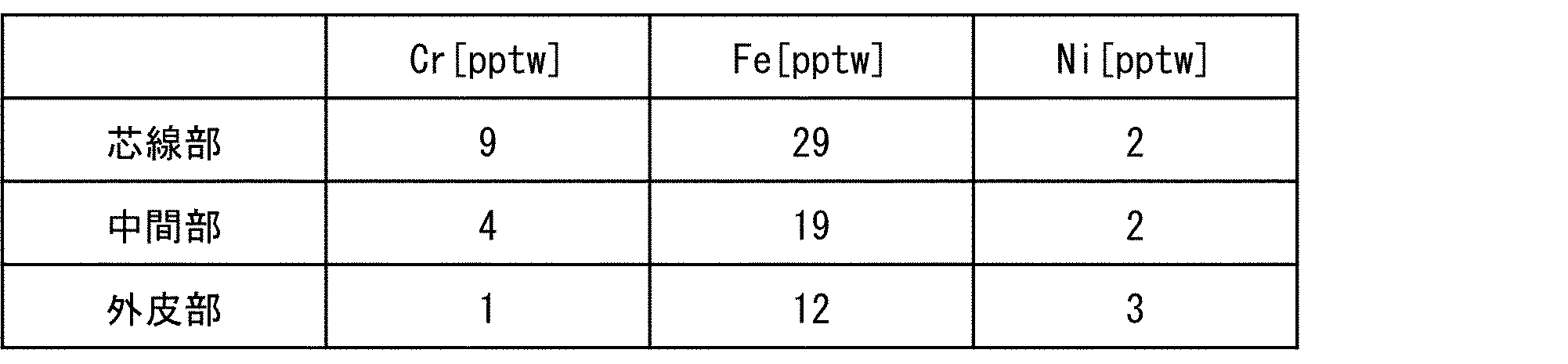
The metal content of each of these measurement samples was analyzed. Specifically, the amount of each metal element of Cr, Fe, and Ni in the solution obtained by dissolving the target measurement sample in a fluorine mixed solution is analyzed by inductively coupled plasma mass spectrometry (ICP-MS). did. The average value of the analytical values of 10 polycrystalline silicon rods for each measurement sample was determined as the metal concentration in the site of each polycrystalline silicon rod. As a result of this example, the metal concentration in each part is shown in Table 1 below.
比較例では、供給配管20にフィルタ30Aを設けないこと以外は、前記実施例と同様にして、多結晶シリコンロッドの製造を実施した。得られた多結晶シリコンロッドのそれぞれについて、金属不純物による汚染状況を前記実施例と同様の方法により確認した。本比較例の結果として、各部位中の金属濃度を以下の表2に示した。

表1と表2との対比から明らかなように、前記実施例の多結晶シリコンロッドは、本比較例の多結晶シリコンロッドに比べて、芯線部、中間部及び外皮部のいずれにおいても、Cr、Fe、Niの各金属濃度が大きく低減された。この結果により、供給配管20にフィルタ30Aを設けることによる金属不純物の汚染に係る有意な抑制効果を確認することができた。
In the comparative example, the polycrystalline silicon rod was manufactured in the same manner as in the above embodiment except that the filter 30A was not provided in the supply pipe 20. For each of the obtained polycrystalline silicon rods, the state of contamination by metal impurities was confirmed by the same method as in the above-mentioned example. As a result of this comparative example, the metal concentration in each site is shown in Table 2 below.
As is clear from the comparison between Table 1 and Table 2, the polycrystalline silicon rod of the above-mentioned example has Cr in all of the core wire portion, the intermediate portion and the outer skin portion as compared with the polycrystalline silicon rod of the present comparative example. , Fe, and Ni metal concentrations were significantly reduced. From this result, it was possible to confirm the significant effect of suppressing the contamination of metal impurities by providing the filter 30A in the supply pipe 20.
本発明は、多結晶シリコンの製造に利用することができる。
The present invention can be used for producing polycrystalline silicon.
1 多結晶シリコンの製造装置
10 反応器
20 供給配管(配管)
30、30A、30B、30C、30D フィルタ
31、31A 第1端
32、32A 第2端
33 フィルタ面
111、E1 流入口
G1 原料ガス
S1 多結晶シリコン 1 Polycrystallinesilicon manufacturing equipment 10 Reactor 20 Supply piping (piping)
30, 30A, 30B, 30C, 30D Filter 31, 31A 1st end 32, 32A 2nd end 33 Filter surface 111, E1 Inflow port G1 Raw material gas S1 polycrystalline silicon
10 反応器
20 供給配管(配管)
30、30A、30B、30C、30D フィルタ
31、31A 第1端
32、32A 第2端
33 フィルタ面
111、E1 流入口
G1 原料ガス
S1 多結晶シリコン 1 Polycrystalline
30, 30A, 30B, 30C,
Claims (10)
- シリコン析出用の原料ガスを収容する反応器と、
前記原料ガスが流入するとともに前記反応器に形成される流入口を含む供給流路であって、前記原料ガスを前記反応器内に供給するための前記供給流路を形成する配管と、
前記供給流路に設けられるとともに、前記原料ガスに混入した不純物を除去するフィルタと、を備えることを特徴とする多結晶シリコンの製造装置。 A reactor that houses the raw material gas for silicon precipitation,
A supply flow path including an inflow port formed in the reactor as the raw material gas flows in, and a pipe forming the supply flow path for supplying the raw material gas into the reactor.
An apparatus for producing polycrystalline silicon, which is provided in the supply flow path and includes a filter for removing impurities mixed in the raw material gas. - 前記フィルタは、前記供給流路における前記流入口に設けられることを特徴とする請求項1に記載の多結晶シリコンの製造装置。 The polycrystalline silicon manufacturing apparatus according to claim 1, wherein the filter is provided at the inflow port in the supply flow path.
- 前記原料ガスは、クロロシラン類と水素との混合ガスであることを特徴とする請求項1または2に記載の多結晶シリコンの製造装置。 The polycrystalline silicon manufacturing apparatus according to claim 1 or 2, wherein the raw material gas is a mixed gas of chlorosilanes and hydrogen.
- 前記供給流路を形成する配管は、ステンレス鋼製であることを特徴とする請求項1から3のいずれか1項に記載の多結晶シリコンの製造装置。 The polycrystalline silicon manufacturing apparatus according to any one of claims 1 to 3, wherein the pipe forming the supply flow path is made of stainless steel.
- 前記フィルタの濾過精度は、粒子径が0.3μm以上である粒子に対して90%以上であることを特徴とする請求項1から4のいずれか1項に記載の多結晶シリコンの製造装置。 The polycrystalline silicon manufacturing apparatus according to any one of claims 1 to 4, wherein the filtration accuracy of the filter is 90% or more with respect to particles having a particle size of 0.3 μm or more.
- 前記フィルタの少なくとも一部は、前記流入口から前記供給流路の上流に向かうにつれて先細りするテーパ形状、または、前記供給流路の上流から前記流入口に向かうにつれて先細りするテーパ形状であることを特徴とする請求項1から5のいずれか1項に記載の多結晶シリコンの製造装置。 At least a part of the filter is characterized by having a tapered shape that tapers from the inflow port toward the upstream of the supply flow path, or a tapered shape that tapers from the upstream of the supply flow path toward the inflow port. The polycrystalline silicon manufacturing apparatus according to any one of claims 1 to 5.
- 前記フィルタは、第1端が開放し、前記第1端とは反対側の第2端が閉塞するとともに、前記第1端と前記第2端との間をフィルタ面が延伸する形状であり、
前記第1端および前記第2端が前記供給流路の内壁に沿って並ぶように、前記第1端の外周側が前記供給流路の内壁に固定されることを特徴とする請求項1から6のいずれか1項に記載の多結晶シリコンの製造装置。 The filter has a shape in which the first end is open, the second end opposite to the first end is closed, and the filter surface extends between the first end and the second end.
Claims 1 to 6 are characterized in that the outer peripheral side of the first end is fixed to the inner wall of the supply flow path so that the first end and the second end are lined up along the inner wall of the supply flow path. The polycrystalline silicon manufacturing apparatus according to any one of the above. - シリコン析出用の原料ガスを収容する反応器内に前記原料ガスを供給するための供給流路に設けられるフィルタによって、前記原料ガスに混入した不純物を除去する不純物除去工程と、
前記不純物除去工程で前記不純物が除去された前記原料ガスを前記反応器内に供給することにより、多結晶シリコンを析出させるシリコン析出工程と、を含むことを特徴とする多結晶シリコンの製造方法。 An impurity removing step of removing impurities mixed in the raw material gas by a filter provided in a supply flow path for supplying the raw material gas into a reactor containing the raw material gas for silicon precipitation.
A method for producing polycrystalline silicon, which comprises a silicon precipitation step of precipitating polycrystalline silicon by supplying the raw material gas from which the impurities have been removed into the reactor. - 前記不純物除去工程は、前記原料ガスが前記反応器内に供給される直前に行われることを特徴とする請求項8に記載の多結晶シリコンの製造方法。 The method for producing polycrystalline silicon according to claim 8, wherein the impurity removing step is performed immediately before the raw material gas is supplied into the reactor.
- 請求項8または9に記載の多結晶シリコンの製造方法によって製造されることを特徴とする多結晶シリコン。 Polycrystalline silicon produced by the method for producing polycrystalline silicon according to claim 8 or 9.
Priority Applications (5)
| Application Number | Priority Date | Filing Date | Title |
|---|---|---|---|
| CN202080069173.2A CN114502509A (en) | 2019-10-02 | 2020-09-24 | Apparatus and method for manufacturing polycrystalline silicon, and polycrystalline silicon |
| KR1020227010615A KR20220073750A (en) | 2019-10-02 | 2020-09-24 | Polycrystalline silicon manufacturing apparatus, manufacturing method and polycrystalline silicon |
| EP20872147.2A EP4039644A4 (en) | 2019-10-02 | 2020-09-24 | Apparatus and method for producing polycrystalline silicon, and polycrystalline silicon |
| US17/765,021 US20230002237A1 (en) | 2019-10-02 | 2020-09-24 | Apparatus and method for producing polycrystalline silicon, and polycrystalline silicon |
| JP2021551166A JP7098068B2 (en) | 2019-10-02 | 2020-09-24 | Polycrystalline silicon manufacturing equipment and manufacturing method |
Applications Claiming Priority (2)
| Application Number | Priority Date | Filing Date | Title |
|---|---|---|---|
| JP2019-182377 | 2019-10-02 | ||
| JP2019182377 | 2019-10-02 |
Publications (1)
| Publication Number | Publication Date |
|---|---|
| WO2021065685A1 true WO2021065685A1 (en) | 2021-04-08 |
Family
ID=75337307
Family Applications (1)
| Application Number | Title | Priority Date | Filing Date |
|---|---|---|---|
| PCT/JP2020/036104 WO2021065685A1 (en) | 2019-10-02 | 2020-09-24 | Apparatus and method for producing polycrystalline silicon, and polycrystalline silicon |
Country Status (7)
| Country | Link |
|---|---|
| US (1) | US20230002237A1 (en) |
| EP (1) | EP4039644A4 (en) |
| JP (1) | JP7098068B2 (en) |
| KR (1) | KR20220073750A (en) |
| CN (1) | CN114502509A (en) |
| TW (1) | TW202135256A (en) |
| WO (1) | WO2021065685A1 (en) |
Cited By (1)
| Publication number | Priority date | Publication date | Assignee | Title |
|---|---|---|---|---|
| WO2023140184A1 (en) * | 2022-01-18 | 2023-07-27 | 株式会社トクヤマ | Reaction furnace for producing polycrystalline silicon rod, gas supply nozzle, production method of polycrystalline silicon rod, and polycrystalline silicon rod |
Citations (7)
| Publication number | Priority date | Publication date | Assignee | Title |
|---|---|---|---|---|
| JPS60254614A (en) * | 1984-05-14 | 1985-12-16 | アライド・コーポレーシヨン | Method of chemically depositing conductive titanium silicidefilm by light induction |
| JPH06310444A (en) * | 1993-04-27 | 1994-11-04 | Ryoden Semiconductor Syst Eng Kk | Cvd system for raw-material solution |
| JPH1120895A (en) * | 1997-05-07 | 1999-01-26 | Tokuyama Corp | Method for storing trichlorosilane and silicon tetrachloride |
| JP2004002122A (en) * | 2002-06-03 | 2004-01-08 | Denki Kagaku Kogyo Kk | Method for manufacturing silicon nitride powder |
| JP2005008430A (en) * | 2003-06-16 | 2005-01-13 | Tokuyama Corp | Production method for silicon |
| JP2013212974A (en) * | 2012-03-05 | 2013-10-17 | Tokuyama Corp | Method for producing polycrystalline silicon and method for producing hydrogen gas used in the production method as reducing agent |
| JP2018530511A (en) | 2015-10-14 | 2018-10-18 | ワッカー ケミー アクチエンゲゼルシャフトWacker Chemie AG | Reactor for depositing polycrystalline silicon |
Family Cites Families (3)
| Publication number | Priority date | Publication date | Assignee | Title |
|---|---|---|---|---|
| FR1417109A (en) * | 1962-05-24 | 1965-11-12 | Siemens Ag | Device for obtaining an extremely pure semiconductor material |
| JP5217162B2 (en) * | 2005-12-27 | 2013-06-19 | 住友化学株式会社 | Method for producing polycrystalline silicon |
| US8657958B2 (en) * | 2010-09-02 | 2014-02-25 | Savi Research, Inc. | CVD-Siemens monosilane reactor process with complete utilization of feed gases and total recycle |
-
2020
- 2020-09-24 US US17/765,021 patent/US20230002237A1/en active Pending
- 2020-09-24 CN CN202080069173.2A patent/CN114502509A/en active Pending
- 2020-09-24 KR KR1020227010615A patent/KR20220073750A/en unknown
- 2020-09-24 EP EP20872147.2A patent/EP4039644A4/en active Pending
- 2020-09-24 JP JP2021551166A patent/JP7098068B2/en active Active
- 2020-09-24 WO PCT/JP2020/036104 patent/WO2021065685A1/en unknown
- 2020-09-28 TW TW109133592A patent/TW202135256A/en unknown
Patent Citations (7)
| Publication number | Priority date | Publication date | Assignee | Title |
|---|---|---|---|---|
| JPS60254614A (en) * | 1984-05-14 | 1985-12-16 | アライド・コーポレーシヨン | Method of chemically depositing conductive titanium silicidefilm by light induction |
| JPH06310444A (en) * | 1993-04-27 | 1994-11-04 | Ryoden Semiconductor Syst Eng Kk | Cvd system for raw-material solution |
| JPH1120895A (en) * | 1997-05-07 | 1999-01-26 | Tokuyama Corp | Method for storing trichlorosilane and silicon tetrachloride |
| JP2004002122A (en) * | 2002-06-03 | 2004-01-08 | Denki Kagaku Kogyo Kk | Method for manufacturing silicon nitride powder |
| JP2005008430A (en) * | 2003-06-16 | 2005-01-13 | Tokuyama Corp | Production method for silicon |
| JP2013212974A (en) * | 2012-03-05 | 2013-10-17 | Tokuyama Corp | Method for producing polycrystalline silicon and method for producing hydrogen gas used in the production method as reducing agent |
| JP2018530511A (en) | 2015-10-14 | 2018-10-18 | ワッカー ケミー アクチエンゲゼルシャフトWacker Chemie AG | Reactor for depositing polycrystalline silicon |
Non-Patent Citations (1)
| Title |
|---|
| See also references of EP4039644A4 |
Cited By (2)
| Publication number | Priority date | Publication date | Assignee | Title |
|---|---|---|---|---|
| WO2023140184A1 (en) * | 2022-01-18 | 2023-07-27 | 株式会社トクヤマ | Reaction furnace for producing polycrystalline silicon rod, gas supply nozzle, production method of polycrystalline silicon rod, and polycrystalline silicon rod |
| JP7395793B1 (en) | 2022-01-18 | 2023-12-11 | 株式会社トクヤマ | Reactor for manufacturing polycrystalline silicon rod, gas supply nozzle, method for manufacturing polycrystalline silicon rod, and polycrystalline silicon rod |
Also Published As
| Publication number | Publication date |
|---|---|
| KR20220073750A (en) | 2022-06-03 |
| EP4039644A1 (en) | 2022-08-10 |
| TW202135256A (en) | 2021-09-16 |
| CN114502509A (en) | 2022-05-13 |
| EP4039644A4 (en) | 2024-02-14 |
| JP7098068B2 (en) | 2022-07-08 |
| US20230002237A1 (en) | 2023-01-05 |
| JPWO2021065685A1 (en) | 2021-04-08 |
Similar Documents
| Publication | Publication Date | Title |
|---|---|---|
| US20060086698A1 (en) | Cyclonic flow reaction vessel | |
| WO2021065685A1 (en) | Apparatus and method for producing polycrystalline silicon, and polycrystalline silicon | |
| JP6763428B2 (en) | Polycrystalline silicon rod and its manufacturing method | |
| WO2013057997A1 (en) | Method for producing chloropolysilane, and fluid bed reaction device | |
| JP6619093B2 (en) | Reactor for depositing polycrystalline silicon | |
| JP2008050697A (en) | Silver fine particle and method and apparatus for producing the same | |
| JP2014080352A (en) | Method for depositing polycrystalline silicon | |
| JP2018526307A (en) | Apparatus and method for thermal denitration, use of such apparatus, and products obtained using such method | |
| US20070110619A1 (en) | Device and process for the deposition of ultrafine particles from the gas phase | |
| JP6154074B2 (en) | Method for crushing polycrystalline silicon fragments and polycrystalline silicon rods | |
| WO2021039569A1 (en) | Polycrystalline silicon rod and method for manufacturing same | |
| WO2021100286A1 (en) | Filter | |
| KR20210026074A (en) | apparatus for collecting SiOx nano powder | |
| JP7395793B1 (en) | Reactor for manufacturing polycrystalline silicon rod, gas supply nozzle, method for manufacturing polycrystalline silicon rod, and polycrystalline silicon rod | |
| CN212188168U (en) | Fin wire mesh gas-liquid separator | |
| CN216512891U (en) | Silicon core structure of polycrystalline silicon reduction furnace and polycrystalline silicon reduction furnace | |
| US20230026255A1 (en) | Method For the Preparation of Single-Walled Carbon Nanotubes | |
| JP2009292675A (en) | Manufacturing method and device for silicon or halogenated silane | |
| WO2011071032A1 (en) | Process for production of polycrystalline silicon, and reaction furnace for production of polycrystalline silicon | |
| JP2004143485A (en) | Method and apparatus for producing fine metal powder | |
| KR20160124519A (en) | Horizontal Type Reactor For Producing Polycrystalline Silicon | |
| JP2009167022A (en) | Apparatus for producing silicon |
Legal Events
| Date | Code | Title | Description |
|---|---|---|---|
| 121 | Ep: the epo has been informed by wipo that ep was designated in this application |
Ref document number: 20872147 Country of ref document: EP Kind code of ref document: A1 |
|
| ENP | Entry into the national phase |
Ref document number: 2021551166 Country of ref document: JP Kind code of ref document: A |
|
| NENP | Non-entry into the national phase |
Ref country code: DE |
|
| ENP | Entry into the national phase |
Ref document number: 2020872147 Country of ref document: EP Effective date: 20220502 |