WO2021065611A1 - 通信制御方法及び中継装置 - Google Patents
通信制御方法及び中継装置 Download PDFInfo
- Publication number
- WO2021065611A1 WO2021065611A1 PCT/JP2020/035755 JP2020035755W WO2021065611A1 WO 2021065611 A1 WO2021065611 A1 WO 2021065611A1 JP 2020035755 W JP2020035755 W JP 2020035755W WO 2021065611 A1 WO2021065611 A1 WO 2021065611A1
- Authority
- WO
- WIPO (PCT)
- Prior art keywords
- bsr
- iab node
- amount
- preemptive
- upstream data
- Prior art date
- Legal status (The legal status is an assumption and is not a legal conclusion. Google has not performed a legal analysis and makes no representation as to the accuracy of the status listed.)
- Ceased
Links
Images


Classifications
-
- H—ELECTRICITY
- H04—ELECTRIC COMMUNICATION TECHNIQUE
- H04B—TRANSMISSION
- H04B7/00—Radio transmission systems, i.e. using radiation field
- H04B7/14—Relay systems
- H04B7/15—Active relay systems
- H04B7/155—Ground-based stations
- H04B7/15528—Control of operation parameters of a relay station to exploit the physical medium
-
- H—ELECTRICITY
- H04—ELECTRIC COMMUNICATION TECHNIQUE
- H04W—WIRELESS COMMUNICATION NETWORKS
- H04W72/00—Local resource management
- H04W72/20—Control channels or signalling for resource management
- H04W72/21—Control channels or signalling for resource management in the uplink direction of a wireless link, i.e. towards the network
-
- H—ELECTRICITY
- H04—ELECTRIC COMMUNICATION TECHNIQUE
- H04W—WIRELESS COMMUNICATION NETWORKS
- H04W72/00—Local resource management
- H04W72/12—Wireless traffic scheduling
- H04W72/1263—Mapping of traffic onto schedule, e.g. scheduled allocation or multiplexing of flows
- H04W72/1268—Mapping of traffic onto schedule, e.g. scheduled allocation or multiplexing of flows of uplink data flows
-
- H—ELECTRICITY
- H04—ELECTRIC COMMUNICATION TECHNIQUE
- H04W—WIRELESS COMMUNICATION NETWORKS
- H04W80/00—Wireless network protocols or protocol adaptations to wireless operation
- H04W80/02—Data link layer protocols
-
- H—ELECTRICITY
- H04—ELECTRIC COMMUNICATION TECHNIQUE
- H04W—WIRELESS COMMUNICATION NETWORKS
- H04W84/00—Network topologies
- H04W84/02—Hierarchically pre-organised networks, e.g. paging networks, cellular networks, WLAN [Wireless Local Area Network] or WLL [Wireless Local Loop]
- H04W84/04—Large scale networks; Deep hierarchical networks
- H04W84/042—Public Land Mobile systems, e.g. cellular systems
- H04W84/047—Public Land Mobile systems, e.g. cellular systems using dedicated repeater stations
-
- H—ELECTRICITY
- H04—ELECTRIC COMMUNICATION TECHNIQUE
- H04W—WIRELESS COMMUNICATION NETWORKS
- H04W88/00—Devices specially adapted for wireless communication networks, e.g. terminals, base stations or access point devices
- H04W88/14—Backbone network devices
Definitions
- the present disclosure relates to a communication control method and a relay device used in a mobile communication system.
- IAB Integrated Access and Backhaul
- Such a relay device has a user device function unit and a base station function unit, and uses the user device function unit to perform wireless communication with a higher-level device (base station or higher-level relay device) and also to perform wireless communication with the base station. Wireless communication with a lower device (user device or lower relay device) is performed using the functional unit.
- the communication control method includes a base station function unit that wirelessly connects to a lower device and a user device function unit that wirelessly connects to a higher device, and upgrades from the lower device to the higher device.
- This is a method executed in a relay device that relays stream data.
- the number of target hops indicating how many hops ahead of the relay device to be the target of the buffer status report is set, and the number of target hops corresponding to the set number of target hops is not yet set. It includes transmitting the buffer state report indicating the amount of transmission upstream data to the host device.
- the relay device has a base station function unit that wirelessly connects to the lower device and a user device function unit that wirelessly connects to the upper device, and is upstream from the lower device to the higher device. It is a device that relays data.
- the relay device performs a process of setting a target hop number indicating how many hops ahead of the relay device to be targeted for buffer status reporting, and a non-transmission of each device corresponding to the set target hop number.
- the processor includes a processor that executes a process of transmitting the buffer state report indicating the amount of upstream data to the higher-level device.
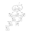
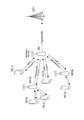
- FIG. 1 is a diagram showing a configuration of a mobile communication system 1 according to an embodiment.
- the mobile communication system 1 is a fifth generation (5G) mobile communication system based on the 3GPP standard.
- the wireless access system in the mobile communication system 1 is NR (New Radio), which is a 5G wireless access system.
- NR New Radio
- LTE Long Term Evolution
- the mobile communication system 1 has a 5G core network (5GC) 10, a user device (UE: User Equipment) 100, a base station (called gNB) 200, and an IAB node 300.
- the IAB node 300 is an example of a relay device.
- the base station is an NR base station
- the base station may be an LTE base station (that is, eNB).
- the 5GC10 has an AMF (Access and Mobility Management Function) 11 and an UPF (User Plane Function) 12.
- the AMF 11 is a device that performs various mobility controls and the like for the UE 100.
- the AMF 11 manages information on the area in which the UE 100 is located by communicating with the UE 100 using NAS (Non-Access Stratum) signaling.
- the UPF 12 is a device that controls the transfer of user data and the like.
- the gNB 200 is connected to the 5GC10 via an interface called an NG interface. In FIG. 1, three gNB200-1 to gNB200-3 connected to 5GC10 are illustrated.
- the gNB 200 is a fixed wireless communication device that performs wireless communication with the UE 100. When the gNB 200 has a donor function, the gNB 200 performs wireless communication with an IAB node that wirelessly connects to itself.
- the gNB 200 is connected to another gNB 200 in an adjacent relationship via an inter-base station interface called an Xn interface.
- FIG. 1 shows an example in which gNB200-1 is connected to gNB200-2 and gNB200-2.
- Each gNB200-1 may have an aggregation unit (CU: Central Unit) and a distribution unit (DU: Distributed Unit).
- CU Central Unit
- DU Distributed Unit
- Each gNB 200 manages one or more cells.
- Cell is used as a term to indicate the smallest unit of wireless communication area.
- the cell may be used as a term for a function or resource for wireless communication with the UE 100.
- One cell belongs to one carrier frequency.
- the UE 100 is a mobile wireless communication device that performs wireless communication with the gNB 200.
- the UE 100 may perform wireless communication with the IAB node 300.
- the UE 100 may be a device that performs wireless communication with the gNB 200 or the IAB node 300.
- the UE 100 is a mobile phone terminal, a tablet terminal, a notebook PC, a sensor or a device provided in the sensor, and / or a vehicle or a device provided in the vehicle.
- FIG. 1 shows an example in which UE 100-1 is wirelessly connected to gNB200-1, UE100-2 is wirelessly connected to IAB node 300-1, and UE100-3 is wirelessly connected to IAB node 300-2. ing.
- UE100-1 directly communicates with gNB200-1.
- the UE 100-2 indirectly communicates with the gNB 200-1 via the IAB node 300-1.
- the UE 100-3 indirectly communicates with the gNB 200-1 via the IAB node 300-1 and the IAB node 300-2.
- the IAB node 300 is a device (relay device) that intervenes in the communication between the eNB 200 and the UE 100 and relays the communication.
- FIG. 1 shows an example in which the IAB node 300-1 is wirelessly connected to the donor device gNB200-1 and the IAB node 300-2 is wirelessly connected to the IAB node 300-1.
- Each IAB node 300 manages a cell.
- the cell ID of the cell managed by the IAB node 300 may be the same as or different from the cell ID of the cell of the donor gNB200-1.
- the IAB node 300 has a UE function unit (user device function unit) and a gNB function unit (base station function unit).
- a UE functional unit may be referred to as MT
- a gNB functional unit may be referred to as DU.
- the IAB node 300 performs wireless communication with a higher-level device (gNB 200 or a higher-level IAB node 300) by its own UE functional unit (MT), and also performs wireless communication with a lower-level device (UE 100 or lower IAB) by its own gNB functional unit (DU). Wireless communication with node 300) is performed.
- the UE function unit (MT) means at least a part of the functions of the UE 100, and the IAB node 300 does not necessarily have all the functions of the UE 100.
- the gNB functional unit (DU) means at least a part of the functions of the gNB 200, and the IAB node 300 does not necessarily have all the functions of the gNB 200.
- the gNB functional unit (DU) may not have an RRC layer, a PDCP layer, or the like.
- the radio section between the UE 100 and the IAB node 300 or gNB 200 may be referred to as an access link (or Uu).
- the radio section between the IAB node 300 and the gNB 200 or other IAB node 300 may be referred to as a backhaul link (or Un).
- a backhaul link may be referred to as a fronthaul link.
- a millimeter wave band may be used for the access link and the backhaul link.
- the access link and the backhaul link may be multiplexed by time division and / or frequency division.
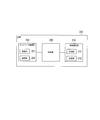
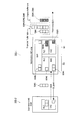
- FIG. 2 is a diagram showing the configuration of gNB 200.
- the gNB 200 has a wireless communication unit 210, a network communication unit 220, and a control unit 230.
- the wireless communication unit 210 is used for wireless communication with the UE 100 and wireless communication with the IAB node 300.
- the wireless communication unit 210 has a receiving unit 211 and a transmitting unit 212.
- the receiving unit 211 performs various types of reception under the control of the control unit 230.
- the receiving unit 211 includes an antenna, converts the radio signal received by the antenna into a baseband signal (received signal), and outputs the radio signal to the control unit 230.
- the transmission unit 212 performs various transmissions under the control of the control unit 230.
- the transmission unit 212 includes an antenna, converts a baseband signal (transmission signal) output by the control unit 230 into a radio signal, and transmits the baseband signal (transmission signal) from the antenna.
- the network communication unit 220 is used for wired communication (or wireless communication) with 5GC10 and wired communication (or wireless communication) with another adjacent gNB200.
- the network communication unit 220 has a reception unit 221 and a transmission unit 222.
- the receiving unit 221 performs various types of reception under the control of the control unit 230.
- the receiving unit 221 receives a signal from the outside and outputs the received signal to the control unit 230.
- the transmission unit 222 performs various transmissions under the control of the control unit 230.
- the transmission unit 222 transmits the transmission signal output by the control unit 230 to the outside.
- the control unit 230 performs various controls on the gNB 200.
- the control unit 230 includes at least one memory and at least one processor electrically connected to the memory.
- the memory stores a program executed by the processor and information used for processing by the processor.
- the processor may include a baseband processor and a CPU.
- the baseband processor modulates / demodulates and encodes / decodes the baseband signal.
- the CPU executes a program stored in the memory to perform various processes.
- the processor executes a process described later.
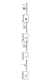
- FIG. 3 is a diagram showing the configuration of the IAB node 300.
- the IAB node 300 has a wireless communication unit 310 and a control unit 320.
- the IAB node 300 may have a plurality of wireless communication units 310.
- the wireless communication unit 310 is used for wireless communication with the gNB 200 (backhaul link) and wireless communication with the UE 100 (access link).
- the wireless communication unit 310 for backhaul link communication and the wireless communication unit 310 for access link communication may be provided separately.
- the wireless communication unit 310 has a receiving unit 311 and a transmitting unit 312.
- the receiving unit 311 performs various types of reception under the control of the control unit 320.
- the receiving unit 311 includes an antenna, converts the radio signal received by the antenna into a baseband signal (received signal), and outputs the radio signal to the control unit 320.
- the transmission unit 312 performs various transmissions under the control of the control unit 320.
- the transmission unit 312 includes an antenna, converts the baseband signal (transmission signal) output by the control unit 320 into a radio signal, and transmits the baseband signal (transmission signal) from the antenna.
- the control unit 320 performs various controls on the IAB node 300.
- the control unit 320 includes at least one memory and at least one processor electrically connected to the memory.
- the memory stores a program executed by the processor and information used for processing by the processor.
- the processor may include a baseband processor and a CPU.
- the baseband processor modulates / demodulates and encodes / decodes the baseband signal.
- the CPU executes a program stored in the memory to perform various processes.
- the processor executes a process described later.
- FIG. 4 is a diagram showing the configuration of the UE 100. As shown in FIG. 4, the UE 100 has a wireless communication unit 110 and a control unit 120.
- the wireless communication unit 110 is used for wireless communication on the access link, that is, wireless communication with the gNB 200 and wireless communication with the IAB node 300.
- the wireless communication unit 110 has a receiving unit 111 and a transmitting unit 112.
- the receiving unit 111 performs various types of reception under the control of the control unit 120.
- the receiving unit 111 includes an antenna, converts the radio signal received by the antenna into a baseband signal (received signal), and outputs the radio signal to the control unit 120.
- the transmission unit 112 performs various transmissions under the control of the control unit 120.
- the transmission unit 112 includes an antenna, converts a baseband signal (transmission signal) output by the control unit 120 into a radio signal, and transmits the baseband signal (transmission signal) from the antenna.
- the control unit 120 performs various controls on the UE 100.
- the control unit 120 includes at least one memory and at least one processor electrically connected to the memory.
- the memory stores a program executed by the processor and information used for processing by the processor.
- the processor may include a baseband processor and a CPU.
- the baseband processor modulates / demodulates and encodes / decodes the baseband signal.
- the CPU executes a program stored in the memory to perform various processes.
- the processor executes a process described later.
- FIG. 5 is a diagram showing an example of the network configuration of the mobile communication system 1 according to the embodiment.
- the mobile communication system 1 uses NR for the backhaul to enable wireless relay of NR access.
- the donor gNB200-1 is a terminal node of the NR backhaul on the network side, and is a gNB200 having an additional function of supporting IAB.
- the backhaul can be multi-hop through multiple hops.
- the gNB 200 may be separated into a gNB-CU function and a gNB-DU function.
- Each IAB node 300 has a gNB-DU function (base station function unit).
- the gNB-DU function is simply referred to as "DU”.
- the DU terminates the NR Uu radio interface to the UE 100 and lower IAB nodes.
- the DU also supports the F1 protocol to gNB-CU (hereinafter simply referred to as "CU") on donor gNB200-1.
- Neighboring nodes (ie, subordinate devices) on the DU's NR access interface are sometimes referred to as "child nodes.”
- Each IAB node 300 supports an NR Uu wireless interface with an MT function (UE function unit).
- the MT function is simply referred to as "MT".
- the MT connects to the upper IAB node or the DU of the donor gNB200-1, and also connects to the CU of the donor gNB200-1 using the RRC.
- MT establishes a signaling radio bearer (SRB) carrying RRC and NAS messages with donor gNB200-1.
- SRB signaling radio bearer
- Adjacent nodes (ie, host devices) on the MT's NR Uu radio interface are sometimes referred to as "parent nodes.”
- All IAB nodes 300 connected to the donor gNB200-1 via one or more hops form a DAG (Directed Acyclic Graph) topology with the donor gNB200-1 as the root.
- This DAG topology is sometimes referred to as the IAB topology.
- upstream refers to the direction of the parent node and "downstream” refers to the direction of the child node.
- the F1 protocol refers to a communication protocol between CU and DU.
- the F1 protocol includes a control plane protocol, the F1-C protocol, and a user plane protocol, the F1-U protocol.
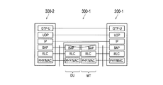
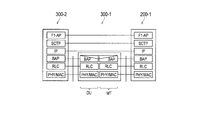
- FIG. 6 is a diagram showing an example of a protocol stack for the F1-U protocol.
- the donor gNB200-1 includes GTP-U (GPRS Tunneling Protocol for User Plane), UDP (User Datagram Protocol), IP (Internet Protocol), and BAP (Backhaul Protocol). It has (Radio Link Control), MAC (Medium Access Control), and PHY (Physical layer) layers.
- GTP-U GPRS Tunneling Protocol for User Plane
- UDP User Datagram Protocol
- IP Internet Protocol
- BAP Backhaul Protocol
- It has (Radio Link Control), MAC (Medium Access Control), and PHY (Physical layer) layers.
- the downstream IAB node 300-2 communicates with the donor gNB200-1 via the intermediate node IAB node 300-1.
- the IAB node 300-2 like the donor gNB200-1, has layers of GTP-U, UDP, IP, BAP, RLC, MAC, and PHY.
- the IAB node 300-1 which is an intermediate node, has each functional part of MT and DU.
- the MT has layers of BAP, RLC, MAC, and PHY.
- the DU has layers of BAP, RLC, MAC, and PHY.
- FIG. 6 shows an example in which the BAP layer of the DU and the BAP layer of the MT are separately provided, the BAP layer of the DU and the BAP layer of the MT may be integrated.
- the PHY layer performs coding / decoding, modulation / demodulation, antenna mapping / demapping, and resource mapping / demapping. Data and control information are transmitted between the PHY layers via physical channels.
- the MAC layer performs priority control of data and retransmission processing by hybrid ARQ (HARQ). Data and control information are transmitted between the MAC layers via a transport channel.
- the MAC layer of the donor gNB200 and the MAC layer of the DU include a scheduler. The scheduler determines the transport format (transport block size, modulation / coding method (MCS)) of the upper and lower links and the resource block allocated to the UE 100.
- MCS modulation / coding method
- the RLC layer transmits data to the receiving RLC layer by using the functions of the MAC layer and the PHY layer. Data and control information are transmitted between the RLC layers via a logical channel.
- the BAP layer performs routing processing and bearer mapping / demapping processing in the user plane.
- FIG. 7 is a diagram showing an example of a protocol stack for the F1-C protocol. Here, the differences from the F1-U protocol will be described.
- the donor gNB200-1 has F1-AP (Application Protocol) and SCTP (Stream Control Transmission Protocol) layers instead of the GTP-U and UDP layers shown in FIG. .
- the downstream IAB node 300-2 has F1-AP and SCPP layers instead of the GTP-U and UDP layers shown in FIG.
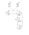
- FIG. 8 is a diagram showing an operation related to the preemptive BSR according to the embodiment.
- the IAB node 300-1 is an intermediate IAB node (Intermediate IAB node), and the IAB node 300-2 is a downstream IAB node (Downstream IAB node).
- the lower device of the IAB node 300-1 is the downstream IAB node
- the lower device of the IAB node 300-1 may be the UE 100.
- the superior device of the IAB node 300-1 is the donor gNB200-1
- the superior device of the IAB node 300-1 may be an upstream IAB node. That is, at least one IAB node may intervene between the IAB node 300-1 and the donor gNB200-1.
- the IAB node 300-1 has a DU that wirelessly connects to the IAB node 300-2 and an MT that wirelessly connects to the host device, and relays upstream data from the IAB node 300-2 to the host device.
- the MT MAC layer transmits a preemptive BSR (Preemptive BSR) indicating the amount of untransmitted upstream data to a higher-level device.
- Preemptive BSR Preemptive BSR
- the BSR transmitted by the UE 100 sets the amount of untransmitted data (that is, the amount of uplink buffer) of each layer of MAC, RLC, and PDCP as a logical channel group (LCG). It is shown for each.
- Each LCG consists of at least one logical channel and is a group set according to priority.
- Legacy BSR formats include short BSR and long BSR.
- the short BSR includes a field in which the LCG ID is stored and a buffer size field in which information indicating the amount of untransmitted data is stored.
- the long BSR includes a field in which a bit string indicating the presence or absence of a buffer size field for each LCG is stored, and a plurality of buffer size fields.
- the gNB 200 grasps the amount of untransmitted data of the UE 100 for each LCG based on the BSR from the UE 100, and schedules the UE 100 to allocate the uplink radio resource corresponding to the amount of the untransmitted data.
- the IAB node 300-1 has a DU (base station function unit) as well as an MT (UE function unit), and there may be an IAB node 300-2 connected to this DU. Therefore, if only the amount of untransmitted data (Legacy buffer size) of the MT of the IAB node 300-1 is reported to the host device, the host device performs scheduling in consideration of the potential amount of untransmitted data (Expected buffer size). Can't. Therefore, there is a problem that there is a shortage or a delay in allocating the uplink radio resource to the IAB node 300-2.
- DU base station function unit
- MT UE function unit
- the preemptive BSR reflects at least one of the amount of data accumulated in the DU of the IAB node 300-1 and the amount of untransmitted data of the IAB node 300-2 connected to this DU. ..
- the host device can perform scheduling in consideration of the potential amount of untransmitted data, so that it is possible to prevent shortages and delays in the allocation of uplink radio resources. For example, when a radio resource is not allocated to the backhaul link (that is, MT) of the IAB node 300-1, the scheduling request can be transmitted to the upper node by triggering the preemptive BSR. By transmitting this scheduling request, appropriate radio resource allocation can be prepared before the actual upstream data reaches the MT transmission protocol (that is, RLC, MAC).
- the amount of untransmitted upstream data indicated by preemptive BSR includes the following variations A) to C).
- the preemptive BSR indicates the amount of untransmitted upstream data of the own IAB node 300 and the amount of untransmitted upstream data of the lower device connected to the own IAB node 300, respectively.
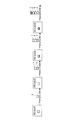
- FIG. 9 is a diagram showing a configuration example 1 of the preemptive BSR according to the embodiment.
- the IAB node # 1 transmits a preemptive BSR indicating the untransmitted upstream data amount A of the own IAB node to the IAB node # 2.
- the IAB node # 2 transmits a preemptive BSR indicating the untransmitted upstream data amount B of the own IAB node and the untransmitted upstream data amount A of the IAB node # 1 to the IAB node # 3.
- the IAB node # 3 transmits a preemptive BSR indicating the untransmitted upstream data amount C of the own IAB node and the untransmitted upstream data amount B of the IAB node # 2 to the IAB node # 4.
- the IAB node # 4 transmits a preemptive BSR indicating the untransmitted upstream data amount D of the own IAB node and the untransmitted upstream data amount C of the IAB node # 3 to the IAB node # 4.
- the preemptive BSR includes the amount of untransmitted upstream data of the own IAB node 300, the amount of untransmitted upstream data of the lower device connected to the own IAB node 300, and the amount of untransmitted data of the lower device of the lower device. Each of is shown.
- FIG. 10 is a diagram showing a configuration example 2 of the preemptive BSR according to the embodiment.
- the IAB node # 1 transmits a preemptive BSR indicating the untransmitted upstream data amount A of the own IAB node to the IAB node # 2.
- the IAB node # 2 transmits a preemptive BSR indicating the untransmitted upstream data amount B of the own IAB node and the untransmitted upstream data amount A of the IAB node # 1 to the IAB node # 3.
- the IAB node # 3 is a preemptive BSR indicating the untransmitted upstream data amount C of the own IAB node, the untransmitted upstream data amount B of the IAB node # 2, and the untransmitted upstream data amount A of the IAB node # 1.
- the IAB node # 4 has the untransmitted upstream data amount D of the own IAB node, the untransmitted upstream data amount C of the IAB node # 3, the untransmitted upstream data amount B of the IAB node # 2, and the IAB node #.
- a preemptive BSR indicating the amount of untransmitted upstream data A of 1 is transmitted to IAB node # 4.
- the preemptive BSR may be a new MAC CE having a format different from that of the legacy BSR.
- the format of the preemptive BSR may be a format having a separate buffer size field in which the amount of untransmitted upstream data of each node is stored.
- the preemptive BSR does not indicate the amount of untransmitted upstream data of the own IAB node 300, but indicates the amount of untransmitted upstream data of the lower device connected to the own IAB node 300.
- the legacy BSR indicates the amount of untransmitted upstream data of the own IAB node 300 to the upper device
- the preemptive BSR indicates the amount of untransmitted upstream data of the lower device. Can be done. Therefore, the preemptive BSR may be used only for reporting the amount of untransmitted upstream data of the lower device. Similar to B) above, it may indicate the amount of untransmitted data of the lower device of the lower device.
- the format of the preemptive BSR may be a new MAC control element (MAC CE) whose format is different from that of the legacy BSR.
- the preemptive BSR may be in a format that has a separate buffer size field for each node.
- the preemptive BSR format may be a diversion of the legacy BSR format.
- the legacy BSR can indicate the amount of untransmitted upstream data for each node.
- the configuration of the preemptive BSR as in A) above is mainly assumed, but the configuration of the preemptive BSR as in B) or C) above may be used.
- the preemptive BSR shows the following data amounts BS # 1 and # 2 in the same manner as the data amount (Legacy buffer size) indicated by the legacy BSR.
- the preemptive BSR indicates at least one of the following data amounts BS # 3 to # 6.
- Data amount BS # 3 indicated by BSR from IAB node 300-2 is a Data amount BS # 3 indicated by BSR from IAB node 300-2.
- the amount of uplink radio resources that is, the size of the uplink grant
- the uplink grant size BS # 3' may be used instead of the data amount BS # 3 indicated by the BSR.
- the DU MAC layer notifies the MT MAC layer of this data amount BS # 3 (MAC data amount).
- the DU MAC layer may indirectly notify the MT MAC layer of the data amount BS # 3 indicated by the BSR from the IAB node 300-2 via the BAP layer, or may notify the BAP layer. You may notify directly without going through.
- the MT MAC layer considers the notified data amount BS # 3 as part of the amount of upstream data retained in the transmission MAC layer of IAB node 300-1 and IAB node 300-1. Calculate the amount of untransmitted upstream data in.
- the MT MAC layer transmits a preemptive BSR (second BSR) indicating the calculated amount of untransmitted upstream data to the higher-level device.
- second BSR preemptive BSR
- the host device can perform scheduling in consideration of the amount of untransmitted upstream data BS # 3 of the IAB node 300-2.
- the DU MAC layer determines whether to notify the MT MAC layer of the data amount BS # 3, that is, whether to enable or disable the notification to the MT MAC layer in logical channel units or LCG units. Alternatively, they may be switched at once.
- the MAC layer of the DU enable notification to the MAC layer of the MT according to the settings made by the donor gNB200-1 to the IAB node 300-1 (for example, the setting by RRC message or F1 message)?
- it may be disabled in logical channel units, LCG units, or in a batch.
- the logical channel or LCG to be notified to the MAC layer of the MT may be specified by the donor gNB200-1.
- the BSR (first BSR) received by the IAB node 300-1 from the IAB node 300-2 may be the configuration of A) above.
- This BSR contains the first buffer state information (first buffer size field) indicating the amount of untransmitted upstream data of the IAB node 300-2 and the untransmitted upstream data of the device further lower than the IAB node 300-2.
- second buffer state information (second buffer size field) indicating the amount.
- the MAC layer of the MT sets the amount of the first untransmitted upstream data indicated by the first buffer state information among the first buffer state information and the second buffer state information to the IAB node 300-1. Treat as part of the amount of upstream data stored in the MAC layer. That is, the MAC layer of the MT sets the amount of untransmitted upstream data of the device lower than the IAB node 300-2 as a part of the amount of upstream data retained in the MAC layer of the IAB node 300-1. Without considering it, a preemptive BSR that does not indicate the amount of untransmitted upstream data of the device below the IAB node 300-2 is generated.
- the DU MAC layer notifies the MT MAC layer of the first buffer state information without notifying the MT MAC layer of the second buffer state information. May be good. This allows the MT MAC layer to generate a preemptive BSR that does not indicate the amount of untransmitted upstream data in the device below the IAB node 300-2.
- the IAB node 300-1 may receive both the preemptive BSR (third BSR) and the legacy BSR (first BSR) of C) above from the IAB node 300-2.
- Such a preemptive BSR indicates the amount of untransmitted upstream data of the device below the IAB node 300-2.
- the legacy BSR indicates the amount of untransmitted upstream data of the IAB node 300-2.
- the MAC layer of the MT has the amount of untransmitted upstream data indicated by the legacy BSR among the preemptive BSR and the legacy BSR of the upstream data retained in the MAC layer of the IAB node 300-1. Treat as part of the quantity. That is, the MAC layer of the MT sets the amount of untransmitted upstream data of the device lower than the IAB node 300-2 as a part of the amount of upstream data retained in the MAC layer of the IAB node 300-1. Without considering it, a preemptive BSR that does not indicate the amount of untransmitted upstream data of the device below the IAB node 300-2 is generated.
- the DU MAC layer may notify the MT MAC layer of the data amount indicated by the legacy BSR without notifying the MT MAC layer of the data amount indicated by the preemptive BSR. This allows the MT MAC layer to generate a preemptive BSR that does not indicate the amount of untransmitted upstream data in the device below the IAB node 300-2.
- the IAB node 300-1 may receive a preemptive BSR diverted from the legacy BSR format from the IAB node 300-2.
- each backhaul link (each node) is associated with the LCG, and the node can be identified by the LCG.
- the legacy BSR has a first buffer state information indicating the amount of untransmitted upstream data associated with the first LCG and a second buffer state information indicating the amount of untransmitted upstream data associated with the second LCG. And include.
- the first LCG is associated with a link (first backhaul link) between the IAB node 300-1 and the IAB node 300-2.
- the second LCG is associated with a link (second backhaul link) between the IAB node 300-2 and the device below the IAB node 300-2.
- the MAC layer of MT sets the amount of untransmitted upstream data indicated by the first buffer state information among the first buffer state information and the second buffer state information to the MAC layer of the IAB node 300-1. Treat as part of the amount of upstream data stored in. That is, the MAC layer of the MT sets the amount of untransmitted upstream data of the device lower than the IAB node 300-2 as a part of the amount of upstream data retained in the MAC layer of the IAB node 300-1. Without considering it, a preemptive BSR that does not indicate the amount of untransmitted upstream data of the device below the IAB node 300-2 is generated.
- the DU MAC layer notifies the MT MAC layer of the first buffer state information without notifying the MT MAC layer of the second buffer state information. May be good. This allows the MT MAC layer to generate a preemptive BSR that does not indicate the amount of untransmitted upstream data in the device below the IAB node 300-2.
- the MAC layer of the DU notifies the MAC layer of the MT of the amount of upstream data BS # 4 (the amount of MAC data) retained in the MAC layer of the DU.
- the amount of upstream data retained in the MAC layer of the DU may be limited to the data that the MAC layer of the DU succeeds in receiving (specifically, decoding).
- the MAC layer of the DU may be a packet for which HARQ ACK has been transmitted to the IAB node 300-2, or the amount of data retained in the HARQ buffer of the MAC layer of the DU may be excluded. ..
- the MAC layer of the DU may indirectly notify the MAC layer of the MT via the BAP layer of the amount of upstream data BS # 4 accumulated in the MAC layer of the DU, or may not go through the BAP layer. May be notified directly to.
- the MT MAC layer considers the notified upstream data amount BS # 4 as part of the amount of upstream data retained in the MAC layer of the IAB node 300-1 and the IAB node 300. Calculate the amount of untransmitted upstream data of -1.
- the MT MAC layer transmits a preemptive BSR indicating the calculated amount of untransmitted upstream data to the host device.
- the host device can perform scheduling in consideration of the amount of upstream data BS # 4 accumulated in the MAC layer of the DU.
- the DU MAC layer determines whether to notify the MT MAC layer of the data amount BS # 4, that is, whether to enable or disable the notification to the MT MAC layer in logical channel units or LCG units. Alternatively, they may be switched at once. For example, does the MAC layer of the DU enable notification to the MAC layer of the MT according to the settings made by the donor gNB200-1 to the IAB node 300-1 (for example, the setting by RRC message or F1 message)? Alternatively, it may be disabled in logical channel units, LCG units, or in a batch. Specifically, the logical channel or LCG to be notified to the MAC layer of the MT may be specified by the donor gNB200-1. Alternatively, it may be possible to collectively set whether or not to notify the MAC layer of the MT.
- MAC setting information (MAC main control.) Transmitted by RRC from the donor gNB200-1 to the IAB node 300-1, information (flag, etc.) indicating whether or not to handle as the amount of MAC data for each LCG is provided. It may be possible to set.
- the RLC layer of the DU notifies the MAC layer of the MT of the amount of upstream data BS # 5 (RLC data amount) retained in the RLC layer of the DU.
- the amount of upstream data retained in the RLC layer of the DU may be limited to the data that the RLC layer of the DU succeeds in receiving.
- the RLC layer of the DU may be a packet for which the ARQ ACK has been transmitted to the IAB node 300-2 (that is, a packet other than the packet corresponding to waiting for the transmission of the ARQ ACK), or the ARQ buffer of the RLC layer of the DU.
- the amount of data retained in the sliding window may be excluded.
- the RLC layer of the DU may indirectly notify the MAC layer of the MT via the BAP layer of the amount of upstream data BS # 5 accumulated in the RLC layer of the DU, or may not go through the BAP layer. May be notified directly to.
- the MT MAC layer considers the amount of notified upstream data as part of the amount of upstream data retained in the RLC layer of IAB node 300-1 and of IAB node 300-1. Calculate the amount of untransmitted upstream data.
- the MT MAC layer transmits a preemptive BSR indicating the calculated amount of untransmitted upstream data to the host device.
- the host device can perform scheduling in consideration of the amount of upstream data BS # 5 accumulated in the RLC layer of the DU.
- the RLC layer of the DU may switch whether to enable or disable the notification of the data amount BS # 5 to the MAC layer of the MT on a logical channel basis or in a batch.
- the RLC layer of the DU is a logical channel to enable or disable notifications depending on the settings made by the donor gNB200-1 to the IAB node 300-1 (for example, the settings by RRC message or F1 message). It may be switched in units or in batches.
- logical channel setting information (logical channel configuration.) Transmitted by RRC from the donor gNB200-1 to the IAB node 300-1
- Amount of upstream data accumulated in the BAP layer BS # 6 First, the BAP layer of the IAB node 300-1 notifies the MAC layer of the MT of the amount of upstream data BS # 6 (BAP data amount) retained in the BAP layer.
- the BAP layer may also notify the MT MAC layer together with these data amounts.
- the BAP layer may notify the MAC layer of the MT as separate data amounts for MAC, RLC, and BAP.
- the BAP layer may notify the MAC layer of the MT as a separate amount of data for each logical channel ID.
- the BAP layer may notify the MAC layer for each LCG (logical channel group), and the LCG may follow the LCG setting (of the MAC layer) of the MT.
- the BAP layer may add the amount of MAC data and the amount of RLC data to the amount of BAP data and notify the MAC layer of MT as one piece of information.
- the MAC layer of MT considers the notified amount of upstream data BS # 6 as part of the amount of upstream data retained in IAB node 300-1 and of IAB node 300-1. Calculate the amount of untransmitted upstream data.
- the MT MAC layer transmits a preemptive BSR indicating the calculated amount of untransmitted upstream data to the host device.
- the BAP layer may switch whether to enable or disable the notification of the data amount BS # 6 to the MAC layer of the MT on a logical channel basis or in a batch. For example, depending on the setting made by the donor gNB200-1 to the IAB node 300-1 (for example, the setting by the RRC message or the F1 message), whether to enable or disable the notification is set for each logical channel or collectively. You may switch with.
- information indicating whether or not to handle as the amount of BAP data may be set for each logical channel ID.
- the logical channel ID to be set whether or not to handle as the amount of BAP data may be the logical channel ID on the DU side (logical channel ID on the receiving side) or the logical channel ID on the MT side (transmission). It may be a side logical channel ID).
- bearer mapping that is, mapping between the logical channel ID on the DU side and the logical channel ID on the MT side, either one of the logical channel IDs can be used for the setting.
- the target for setting whether or not to handle as the amount of BAP data may be the ID of the source IAB node (that is, the lower device) or the ID of the destination IAB node (that is, the higher device). Good.
- the source and destination may be the most recent IAB node, or may be a source and destination several hops away.
- the IAB node 300-1 has a DU that wirelessly connects to the IAB node 300-2 and an MT that wirelessly connects to the host device, and is upstream from the IAB node 300-2 to the host device. Relay data.
- the IAB node 300-1 transmits a legacy BSR (first buffer state report) indicating the amount of untransmitted upstream data of the IAB node 300-1 to a higher-level device. Further, the IAB node 300-1 transmits at least a preemptive BSR (second buffer state report) indicating the amount of untransmitted upstream data of the IAB node 300-2 to the higher-level device. For example, the preemptive BSR indicates the total amount of untransmitted upstream data of the IAB node 300-1 and the amount of untransmitted upstream data of the IAB node 300-2.
- the host device sets the amount of untransmitted upstream data for each hop, that is, the amount of untransmitted upstream data for IAB node 300-1, and the amount of untransmitted upstream data for IAB node 300-2, based on the legacy BSR and preemptive BSR. You can grasp each of the amount of untransmitted upstream data.
- the host device subtracts the data amount indicated by the legacy BSR from the IAB node 300-1 from this total data amount, so that the untransmitted upstream of the IAB node 300-2 The amount of data can be estimated.
- the general legacy BSR trigger conditions include the following three trigger conditions a) to c).
- First trigger condition indicating that a predetermined upstream data exists For example, the first trigger condition is that the upstream data arrives in the buffer and the priority of the upstream data is higher than that of the existing data.
- the BSR transmitted in response to the satisfaction of the first trigger condition may be referred to as a "regular BSR".
- Second trigger condition indicating the expiration of the periodic timer is that the periodic timer has expired. Since the periodic timer is restarted as soon as it expires, the BSR will be transmitted periodically. The BSR transmitted in response to the satisfaction of the second trigger condition is sometimes referred to as a "periodic BSR".
- the third trigger condition is that the size of the padding area of the transmission MAC PDU (Protocol Data Unit) is BSR MAC CE or more.
- the BSR transmitted in response to the satisfaction of the third trigger condition may be referred to as a "padding BSR".
- the preemptive BSR trigger condition is different from the legacy BSR trigger condition. This makes it possible to transmit the preemptive BSR from the IAB node 300-1 to the host device at an appropriate timing.
- Trigger conditions 1 to 4 As a trigger condition for preemptive BSR, at least one of the following Examples 1 to 4 can be applied. Which of the following Trigger conditions 1 to 4 is used and various settings related to the trigger conditions may be set for the donor gNB200-1 to the IAB node 300-1.
- the candidates for the trigger condition of the BSR include the first trigger condition indicating that the predetermined upstream data exists in the IAB node 300-1, and the expiration of the periodic timer in the IAB node 300-1. There is a second trigger condition and a third trigger condition indicating that the transmission padding size from the IAB node 300-1 to the higher-level device satisfies the predetermined condition.
- some of the first trigger conditions to the third trigger conditions are applied to the legacy BSR, and the remaining trigger conditions are applied to the preemptive BSR.
- the MAC layer of the MT of the IAB node 300-1 applies the regular BSR (first trigger condition) and the periodic BSR (second trigger condition) to the preemptive BSR, and the padding BSR (third trigger condition). To the legacy BSR.
- the MAC layer of the MT of the IAB node 300-1 applies the regular BSR (first trigger condition) to the preemptive BSR, and applies the periodic BSR (second trigger condition) and padding BSR (third trigger condition) to the legacy BSR. Applies to.
- the MAC layer of the MT of the IAB node 300-1 applies the periodic BSR (second trigger condition) to the preemptive BSR, and applies the regular BSR (first trigger condition) and the padding BSR (third trigger condition) to the legacy BSR. Applies to.
- the preemptive BSR indicates at least the amount of untransmitted upstream data at IAB node 300-2.
- the legacy BSR indicates the amount of untransmitted upstream data at IAB node 300-1.
- the legacy BSR is the untransmitted upstream of at least one of the BAP layer, the RLC layer of the DU, and the MAC layer of the DU, in addition to the amount of untransmitted upstream data of the MT of the IAB node 300-1. It may indicate the amount of data.
- the trigger condition for transmitting the preemptive BSR is that the periodic timer set for periodically transmitting the preemptive BSR (hereinafter referred to as "periodic timer for preemptive BSR”) has expired. Includes one condition.
- the IAB node 300-1 has another periodic timer (hereinafter, referred to as “periodic timer for legacy BSR”) for periodically transmitting the legacy BSR.
- the periodic timer for the legacy BSR is used for the second trigger condition described above.
- the periodic timer for the preemptive BSR and the periodic timer for the legacy BSR may be set from the donor gNB200-1 to the IAB node 300-1.
- the MAC layer of the MT of the IAB node 300-1 transmits the preemptive BSR to the higher-level device when the first condition is satisfied. In other words, the MAC layer of the MT of the IAB node 300-1 periodically transmits the preemptive BSR using the periodic timer for the preemptive BSR.
- the trigger condition for transmitting the preemptive BSR is the BSR indicating the amount of untransmitted upstream data of the lower device IAB node 300-2 from the start to the expiration of the periodic timer for the preemptive BSR. It may further include a second condition that the IAB node 300-1 has received at least one (third buffer state report). That is, when the periodic timer for the preemptive BSR expires, if the BSR (third buffer state report) is received, the preemptive BSR is triggered. Alternatively, if no BSR (third buffer status report) has been received when the periodic timer for the preemptive BSR expires, the preemptive BSR is not triggered (skipped).
- the BSR (third buffer state report) from the lower device may be a preemptive BSR or a legacy BSR.
- the MAC layer of the MT of the IAB node 300-1 transmits the preemptive BSR according to the satisfaction of the first condition and the second condition.
- the MAC layer of the MT of the IAB node 300-1 is a subordinate device, the IAB node 300-2, from the start to the expiration of the periodic timer for the preemptive BSR, that is, within one transmission cycle of the preemptive BSR.
- the preemptive BSR is transmitted once to the host device.
- the preemptive BSR is higher. Do not send to the device.
- the presence or absence of BSR (third buffer status report) reception from the lower device was used as the criterion, but it is not limited to this.
- the determination may be made based on the presence or absence of information on the amount of data to be reported using the preemptive BSR.
- the IAB node 300-1 triggers the preemptive BSR when there is information on the amount of data to be transmitted from the lower device, or when there is data staying in the DU of the own node.
- the IAB node 300-1 may determine whether or not UL grant (radio resource allocation for uplink data transmission) has been performed to the lower device instead of whether or not the BSR has been received.
- FIG. 11 is a diagram showing an example of an assumed scenario in this operation example.
- the MAC layer of the DU of the IAB node 300-1 is the lower device, each IAB node 300-2 (300-2a and 300-2b) and each UE 100-1 (100-1a and 100-).
- the BSR is received from 2b), and an uplink grant is transmitted to each IAB node 300-2 and each UE 100-1.
- UE100-2a and 100-2b are connected to the IAB node 300-2a, and UE100-2c is connected to the IAB node 300-2b.
- the MAC layer of the MT of the IAB node 300-1 transmits the preemptive BSR to the higher-level device donor gNB200-1 according to the conditions of the first condition and the second condition being satisfied. May be good.
- the preemptive BSR can be transmitted from the IAB node 300-1 to the host device at an appropriate timing.
- the trigger condition for transmitting the preemptive BSR includes the condition that the IAB node 300-1 receives the transmission request for the preemptive BSR from the host device.
- This transmission request may be MAC CE or control information transmitted / received at the BAP layer (for example, BAP Control PDU or BAP header).
- the MAC layer of the MT of the IAB node 300-1 transmits the preemptive BSR to the host device in response to receiving the transmission request from the host device. For example, the MAC layer of the MT of the IAB node 300-1 transmits one preemptive BSR to the higher-level device in response to receiving one transmission request from the higher-level device.
- the preemptive BSR can be transmitted to the higher-level device in the form of request / response, that is, in response to the request of the higher-level device.
- preemptive BSR trigger condition 4 the MAC layer of the MT of the IAB node 300-1 uses a timer (hereinafter, referred to as “prohibited timer”) indicating a period during which transmission of the next preemptive BSR is prohibited when the preemptive BSR is transmitted. Start.
- a timer hereinafter, referred to as “prohibited timer”
- the MT MAC layer of IAB node 300-1 avoids the transmission of the next preemptive BSR until the prohibition timer expires.
- the MAC layer of the MT of the IAB node 300-1 enables the transmission of the next preemptive BSR when the prohibition timer expires.
- the IAB node 300-1 When the IAB node 300-1 receives the high priority BSR from the lower device, it may trigger the next preemptive BSR even before the prohibition timer expires.
- the high priority BSR is a BSR received from a UE having an access class having a numerical value larger than a predetermined value, for example, when the lower device is a UE.
- the high priority BSR is a BSR corresponding to a backhaul link (bearer or logical channel) in which a higher priority than a predetermined standard is set when the lower device is an IAB node.
- Examples 1 to 4 described above an example in which the IAB node 300-1 uses the preemptive BSR and the legacy BSR in combination has been described.
- the preemptive BSR configuration as shown in FIGS. 9 and 10 the preemptive BSR configuration is adopted.
- the IAB node 300-1 does not necessarily have to use the legacy BSR.
- the IAB node 300-1 has a DU that wirelessly connects to the lower device and an MT that wirelessly connects to the higher device, and relays upstream data from the lower device to the higher device.
- the IAB node 300-1 sets the number of target hops indicating how many hops from the IAB node 300-1 to the lower device to be the target of the preemptive BSR.
- the IAB node 300-1 transmits a preemptive BSR indicating the amount of untransmitted upstream data of each device corresponding to the set number of target hops to the host device.
- the number of target hops is the number of hops such as 0 hop, 1 hop, and 2 hops.
- the IAB node 300-1 transmits a BSR indicating only the amount of untransmitted upstream data of the own node (IAB node 300-1) to the higher-level device.
- This BSR may be a legacy BSR or a preemptive BSR.
- the IAB node 300-1 When the number of target hops is one hop, the IAB node 300-1 has the amount of untransmitted upstream data of its own node (IAB node 300-1) and the untransmitted upstream device of the lower device IAB node 300-2, which is one hop lower.
- a preemptive BSR (for example, the preemptive BSR shown in FIG. 9) indicating the amount of transmission upstream data is transmitted to the host device.
- the amount of untransmitted upstream data of the IAB node 300-2a and the untransmitted amount of the untransmitted upstream data of the IAB node 300-2b are entered in the buffer size field indicating the amount of untransmitted upstream data of the lower device one hop lower.
- the total value with the amount of upstream data may be included.
- the IAB node 300-1 When the number of target hops is 2 hops, the IAB node 300-1 has the amount of untransmitted upstream data of its own node (IAB node 300-1) and the untransmitted upstream device of the IAB node 300-2, which is a lower device one hop lower.
- a preemptive BSR indicating the amount of transmitted upstream data and the amount of untransmitted upstream data of the lower device two hops lower is transmitted to the higher device.
- the number of target hops set in IAB node # 4 is 2.
- the IAB node # 4 has the untransmitted upstream data amount D of the own node (IAB node # 4), the untransmitted upstream data amount C of the IAB node # 3 one hop lower, and the IAB two hops lower.
- a preemptive BSR indicating the amount of untransmitted upstream data B of node # 2 is transmitted to the host device.
- the information indicating the untransmitted upstream data amount D, the information indicating the untransmitted upstream data amount C, and the information indicating the untransmitted upstream data amount B are included in the individual buffer size fields. It may be.
- the preemptive BSR may also include an identifier indicating the corresponding number of hops for each buffer size field. Specifically, the preemptive BSR may have a hop count field provided for each buffer size field.
- setting the number of target hops means setting whether only the IAB node 300-1 is the target of the BSR or the IAB node 300-1 and the lower device are the targets of the BSR. There may be. In other words, whether or not to include information indicating the amount of untransmitted upstream data of the lower device in the BSR (that is, on / off) may be set.
- the IAB node 300-1 sends the BSR transmitted to the higher-level device the amount of untransmitted upstream data of the MT of the IAB node 300-1 and the untransmitted data of the DU and BAP layers, respectively. It may include the amount of upstream data.
- the IAB node 300-1 may transmit hop number information indicating the set target hop number to the higher-level device.
- the IAB node 300-1 may transmit a preemptive BSR including hop number information to a higher-level device.
- the MAC CE of the preemptive BSR may have a field in which hop number information is stored.
- the hop number information may be transmitted to a higher-level device separately from the preemptive BSR.
- the IAB node 300-1 may transmit the corresponding hop number information to the host device before or after transmitting the preemptive BSR.
- the hop number information indicates how many hops of untransmitted upstream data is indicated by the preemptive BSR. For example, when the hop number information is 0 hops, it indicates that only the amount of untransmitted upstream data of the own node is shown. When the hop number information is one hop, it indicates the amount of untransmitted upstream data of the own node and the amount of untransmitted upstream data of the lower device one hop lower. When the number of hops information is 2 hops, the amount of untransmitted upstream data of the own node, the amount of untransmitted upstream data of the lower device one hop lower, and the amount of untransmitted upstream data of the lower device 2 hops lower are calculated. Represents to show.
- the number of target hops may be specified by a message (first message) transmitted from the donor gNB200-1 to the IAB node 300-1.
- first message a message transmitted from the donor gNB200-1 to the IAB node 300-1.
- the CU of the donor gNB200-1 sets the target hop number to the IAB node 300-1 by transmitting an RRC message or an F1 message containing information specifying the target hop number to the IAB node 300-1. May be good.
- the information that specifies the number of hops may indicate the number of hops of the amount of data to be reported in a fixed manner, or may indicate the upper limit of the number of hops. If the information specifying the number of hops indicates the upper limit of the number of hops, the IAB node 300-1 can change the number of hops each time it reports a preemptive BSR. For example, the IAB node 300-1 changes the number of hops of the amount of data actually reported, up to the specified number of hops, according to the number of bits that can be transmitted by the preemptive BSR (for example, the number of padding bits).
- the DU or BAP layer of the higher-level device sends a message (MAC CE or BAP Control PDU) including information specifying the number of target hops to the IAB node 300-1, so that the number of target hops is the IAB node 300-. It may be set to 1.
- the IAB node 300-1 sends a message (second message) indicating the number of target hops requested by the own node (IAB node 300-1) or the lower device (IAB node 300-2) to the donor gNB200-1. May be sent or forwarded to.
- the DU of each IAB node 300 may include information indicating the number of target hops requested by its own node in the F1 message transmitted to the donor gNB200-1.
- the CU of the donor gNB200-1 can set an appropriate number of target hops for each IAB node 300.
- FIG. 12 is a diagram showing an example of the operation flow of the IAB node 300-1 according to the embodiment.
- step S1 the MAC layer of the IAB node 300-1 sets the number of target hops indicating how many hops from the IAB node 300-1 to the lower device to be the target of the preemptive BSR. ..
- step S2 the MAC layer of the DU of the IAB node 300-1 receives the preemptive BSR from the lower device IAB node 300-2.
- This preemptive BSR may have the configuration of the preemptive BSR as shown in FIG.
- step S3 the MAC layer of the DU of the IAB node 300-1 identifies the amount of untransmitted upstream data of each hop indicated by the preemptive BSR received from the IAB node 300-2, and each identified data amount is used as the IAB node 300. Notify the MAC layer of MT of -1. Further, the MAC layer of the DU of the IAB node 300-1 calculates the amount of upstream data staying in itself, and notifies the calculated amount of data to the MAC layer of the MT of the IAB node 300-1.
- the RLC layer of the DU of the IAB node 300-1 calculates the amount of upstream data accumulated in itself, and notifies the calculated amount of data to the MAC layer of the MT of the IAB node 300-1.
- the BAP layer of the IAB node 300-1 calculates the amount of upstream data accumulated in itself, and notifies the calculated amount of data to the MAC layer of the MT of the IAB node 300-1.
- step S4 the MAC layer of the MT of the IAB node 300-1 determines whether or not the transmission trigger condition of the preemptive BSR, that is, the transmission trigger condition as described in Examples 1 to 4 described above is satisfied.
- step S4: NO the process returns to step S2.
- step S5 when it is determined that the transmission trigger condition of the preemptive BSR is satisfied (step S4: YES), in step S5, the MT MAC layer of the IAB node 300-1 is the MAC, RLC, of the DU of the IAB node 300-1. And, based on the amount of data notified from each layer of the BAP, a preemptive BSR indicating the amount of untransmitted upstream data of each device corresponding to the number of target hops set in step S1 is transmitted to the upper device.
- This preemptive BSR may include hop number information indicating the number of target hops set in step S1.
- the IAB node 300-1 is to show that it is a preemptive BSR.
- the identifier of may be included in the preemptive BSR.
- the preemptive BSR is a BSR that reflects the amount of untransmitted upstream data other than the amount of untransmitted upstream data of the MT.
- the IAB node 300-1 may indicate to the host device that it is a preemptive BSR by including the logical channel ID specified for the preemptive BSR in the header portion (MAC subheader) transmitted together with the BSR MAC CE. Good.
- a base station (hereinafter, referred to as a master base station) that manages each IAB node 300 may exist in addition to the donor gNB 200.
- the master base station may be an LTE base station.
- the MT of each IAB node 300 may have two connections (ie, dual connections), one with a master base station and one with a host device (upper IAB node or donor gNB).
- the master base station may be a master node, and the connection may be an MCG (Master Cell Group) link.
- the higher-level device (upper IAB node or donor gNB) may be a secondary node, and the connection may be an SCG (Secondary Cell Group) link.
- the base station in the mobile communication system 1 may be an eNB which is an LTE base station.
- the core network in the mobile communication system 1 may be an EPC (Evolved Packet Core).
- the gNB may be connected to the EPC
- the eNB may be connected to the 5GC
- the gNB and the eNB may be connected via the inter-base station interface (Xn interface, X2 interface).
- the preemptive BSR may be transmitted by the UE 100, which does not have to belong to the IAB topology.
- the UE 100 may notify as a preemptive BSR by reflecting a data other than the amount of data retained in its own MAC, RLC, PDCP, and SDAP.
- the preemptive BSR may be triggered by, for example, a data amount notification from the application layer.
- a packet for example, a packet having a high priority or a high QoS request
- TSC Time Sensitive Communication: communication with strict time constraint
- a program for causing a computer to execute each process according to the above-described embodiment may be provided.
- the program may also be recorded on a computer-readable medium.
- Computer-readable media can be used to install programs on a computer.
- the computer-readable medium on which the program is recorded may be a non-transient recording medium.
- the non-transient recording medium is not particularly limited, but may be, for example, a recording medium such as a CD-ROM or a DVD-ROM.
- a chipset composed of a memory for storing a program for executing each process performed by the UE 100, the gNB 200, or the IAB node 300 and a processor for executing the program stored in the memory may be provided.
- preemptive BSR regular BSR
- -R2 is a trigger of both types of preemptive BSR (1. based on UL grants provided to child nodes and / or UEs, 2. based on BSRs from child nodes or UEs) in IAB Rel-16 operation. It is assumed that it can be supported. Further consideration is needed as to what is specified.
- the preemptive BSR is used for buffer status reporting based on the amount of data that will be available on the MT, as well as the data available for transmission on the MT's MAC and RLC. There is expected. The agreement itself only mentions the triggering conditions for preemptive BSR, but is implied by the current assumption "1. Based on the UL grant provided to the child node and / or UE, 2. Based on the BSR from the child node or UE". I think it will be done.
- Preemptive BSR is expected to report the buffer size of the MAC, RLC, and BAP of the IAB node in addition to the buffer size of the downstream IAB node / UE, in addition to the existing rules.
- the regular BSR is triggered as shown below.
- the MAC entity determines the amount of UL data that can be used in the logical channel according to the data amount calculation procedure of TS38.322 and TS38.323.
- BSR is triggered when any of the following events occur.
- the UL data of the logical channel belonging to the LCG is made available to the MAC entity; and-the logic in which this UL data has a higher priority than any logical channel containing the available UL data belonging to the LCG.
- the BSR is referred to as the "regular BSR”.
- Finding 2 Regular BSR is triggered when UL data becomes available to the MAC entity according to the data volume calculation procedure in RLC (and PDCP).
- the UE For MAC buffer status reporting, the UE considers the following as the RLC data volume: -RLC SDU and RLC SDU segment not yet included in the RLC data PDU-RLC data PDU with initial transmission pending -RLC data PDU (RLC AM) whose retransmission is pending
- RLC AM initial transmission pending -RLC data PDU
- the UE estimates the size of the STATUS PDU sent at the next transmission opportunity and considers this as part of the RLC data volume. ..
- Finding 3 The existing data volume calculation procedure is applicable only to MT RLC.
- the data volume calculation procedure should be extended to support preemptive BSR.
- the following amount of data should be considered.
- -MAC (receiver, i.e. on DU):
- the buffer size reported by the (existing) BSR from the downstream node / UE, and the MAC PDU and MAC SDU still on the MAC receiver are the amount of MAC data. Be considered.
- RLC reception side, that is, on the DU
- RLC PDU and RLC SDU that are still on the reception side of RLC are regarded as the amount of RLC data.
- BAP PDU still in the routing process is regarded as the amount of BAP data.
- the amount of these additional data is finally notified to the MAC (transmitter, that is, on the MT) and reported in the preemptive BSR.
- Proposal 1 RAN2 will include the buffer size reported by the BSR from the downstream node / UE, and the MAC PDU and MAC SDU still on the receiving side of the MAC in the MAC specifications for data volume calculation. You should agree.
- Proposal 2 RAN2 should agree that RLC PDUs and RLC SDUs, which are still on the receiving side of RLC, are included in the RLC specifications for RLC data volume calculation.
- Proposal 3 RAN2 should agree, for example, that BAP PDUs that are still in the routing process are included in the BAP specifications for BAP data volume calculation.
- the preemptive BSR is used for scheduling radio resources. That is, the behavior of the downstream node (in this case the intermediate node) must be deterministic and controllable. Therefore, activation / deactivation of each procedure should depend on the configuration via RRC or F1-AP.
- Proposal 4 RAN2 should discuss whether additional data volume calculation procedures can be activated / deactivated through configuration via RRC or F1-AP.
- MAC CE format Another point of discussion in the email discussion is whether to reuse the existing BSR MAC CE or define a new preemptive BSR MAC CE. In other words, from the perspective of the upstream DU scheduler, it has not yet been determined whether the "expected data volume" should be distinguished from the existing buffer size.
- the preemptive BSR may include buffer reports for all downstream IAB nodes (ie, children, grandchildren, great-grandchildren: option 1), as shown in FIGS. 9 and 10. It is not clear whether only the closest hop (ie child and itself: option 2) is included.
- Finding 4 It is not clear whether the preemptive BSR includes the buffer size of all downstream nodes on the multi-hop backhaul.
- Option 1 may provide the best performance for low latency scheduling when resource allocation and UL data transmission over multi-hop backhaul are done in a timely manner. Otherwise, overscheduling can occur in upstream backhaul.
- option 2 is a kind of hop-by-hop scheduling, so it is a safer scheme.
- Option 1 is an issue or configurable, a new MAC CE should be introduced to distinguish the expected amount of data from the actual buffered data. If not, I think the existing MAC CE will still work well.
- Proposal 5 RAN2 considers not only the viewpoint of scheduler implementation, but also the details of the expected amount of data (ie, one of the closest downstream nodes, or one of all downstream multi-hop nodes). , It should be discussed whether a new MAC CE will be introduced in preemptive BSR.
- R2 states that "R2 is based on both types of preemptive BSR triggers (1. based on UL grants provided to child nodes and / or UEs, 2. based on BSRs from child nodes or UEs), but IAB Rel- It is assumed that 16 operations can be supported. Further consideration is required as to what is specified. " It can be intended that these triggers occur aperiodically, i.e., be triggered by an event. In addition, the two identified types are based on the plural, ie, multiple "UL grants" and "BSRs".
- triggering a preemptive BSR to the upstream is to provide multiple events downstream, ie BSR reception or UL authorization. is connected with.
- some major problems are observed as follows.
- Proposal 6 RAN2 should discuss preemptive BSR triggers in consideration of multiple downstream nodes.
Landscapes
- Engineering & Computer Science (AREA)
- Computer Networks & Wireless Communication (AREA)
- Signal Processing (AREA)
- Mobile Radio Communication Systems (AREA)
Priority Applications (4)
| Application Number | Priority Date | Filing Date | Title |
|---|---|---|---|
| JP2021550650A JP7332705B2 (ja) | 2019-10-03 | 2020-09-23 | 通信制御方法及び中継装置 |
| EP20870615.0A EP4040841A4 (en) | 2019-10-03 | 2020-09-23 | METHOD FOR COMMUNICATION CONTROL AND RELAY DEVICE |
| US17/711,407 US20220225383A1 (en) | 2019-10-03 | 2022-04-01 | Communication control method and relay apparatus |
| JP2023131270A JP7536966B2 (ja) | 2019-10-03 | 2023-08-10 | 通信制御方法、中継装置及びプロセッサ |
Applications Claiming Priority (2)
| Application Number | Priority Date | Filing Date | Title |
|---|---|---|---|
| US201962909923P | 2019-10-03 | 2019-10-03 | |
| US62/909,923 | 2019-10-03 |
Related Child Applications (1)
| Application Number | Title | Priority Date | Filing Date |
|---|---|---|---|
| US17/711,407 Continuation US20220225383A1 (en) | 2019-10-03 | 2022-04-01 | Communication control method and relay apparatus |
Publications (1)
| Publication Number | Publication Date |
|---|---|
| WO2021065611A1 true WO2021065611A1 (ja) | 2021-04-08 |
Family
ID=75336449
Family Applications (1)
| Application Number | Title | Priority Date | Filing Date |
|---|---|---|---|
| PCT/JP2020/035755 Ceased WO2021065611A1 (ja) | 2019-10-03 | 2020-09-23 | 通信制御方法及び中継装置 |
Country Status (4)
| Country | Link |
|---|---|
| US (1) | US20220225383A1 (https=) |
| EP (1) | EP4040841A4 (https=) |
| JP (2) | JP7332705B2 (https=) |
| WO (1) | WO2021065611A1 (https=) |
Cited By (1)
| Publication number | Priority date | Publication date | Assignee | Title |
|---|---|---|---|---|
| US20240414586A1 (en) * | 2021-10-11 | 2024-12-12 | Apple Inc. | Enhanced QoS Support for Extended Reality (XR) |
Families Citing this family (2)
| Publication number | Priority date | Publication date | Assignee | Title |
|---|---|---|---|---|
| KR20230004518A (ko) * | 2020-04-27 | 2023-01-06 | 엘지전자 주식회사 | 무선 통신 시스템에서 단말의 신호 송수신 방법 및 장치 |
| US12004068B2 (en) * | 2021-11-19 | 2024-06-04 | Qualcomm Incorporated | Multipath IAB communication including multi-hop |
Citations (1)
| Publication number | Priority date | Publication date | Assignee | Title |
|---|---|---|---|---|
| JP2017028434A (ja) * | 2015-07-21 | 2017-02-02 | 日本電信電話株式会社 | 無線通信システム、中継局装置及び無線通信方法 |
Family Cites Families (4)
| Publication number | Priority date | Publication date | Assignee | Title |
|---|---|---|---|---|
| US11395320B2 (en) * | 2018-05-18 | 2022-07-19 | Nokia Solutions And Networks Oy | Predictive scheduling request or buffer status report for wireless backhauling |
| WO2020065446A1 (en) * | 2018-09-26 | 2020-04-02 | Telefonaktiebolaget Lm Ericsson (Publ) | Enhanced uplink scheduling in integrated access backhaul (iab) networks |
| WO2020081729A1 (en) * | 2018-10-18 | 2020-04-23 | Intel Corporation | Latency management for integrated access and backhaul |
| GB2581368B (en) * | 2019-02-14 | 2023-12-06 | Samsung Electronics Co Ltd | Improvements in and relating to scheduling latency in a telecommunication system |
-
2020
- 2020-09-23 JP JP2021550650A patent/JP7332705B2/ja active Active
- 2020-09-23 EP EP20870615.0A patent/EP4040841A4/en active Pending
- 2020-09-23 WO PCT/JP2020/035755 patent/WO2021065611A1/ja not_active Ceased
-
2022
- 2022-04-01 US US17/711,407 patent/US20220225383A1/en not_active Abandoned
-
2023
- 2023-08-10 JP JP2023131270A patent/JP7536966B2/ja active Active
Patent Citations (1)
| Publication number | Priority date | Publication date | Assignee | Title |
|---|---|---|---|---|
| JP2017028434A (ja) * | 2015-07-21 | 2017-02-02 | 日本電信電話株式会社 | 無線通信システム、中継局装置及び無線通信方法 |
Non-Patent Citations (2)
| Title |
|---|
| ASUSTEK: "Discussion on traditional uplink and IAB uplink traffic for BSR triggering", 3GPP TSG RAN WG2 #107 R2-1911218, 16 August 2019 (2019-08-16), XP051768978 * |
| See also references of EP4040841A4 |
Cited By (1)
| Publication number | Priority date | Publication date | Assignee | Title |
|---|---|---|---|---|
| US20240414586A1 (en) * | 2021-10-11 | 2024-12-12 | Apple Inc. | Enhanced QoS Support for Extended Reality (XR) |
Also Published As
| Publication number | Publication date |
|---|---|
| JP7332705B2 (ja) | 2023-08-23 |
| JPWO2021065611A1 (https=) | 2021-04-08 |
| JP7536966B2 (ja) | 2024-08-20 |
| EP4040841A4 (en) | 2023-10-25 |
| JP2023154036A (ja) | 2023-10-18 |
| US20220225383A1 (en) | 2022-07-14 |
| EP4040841A1 (en) | 2022-08-10 |
Similar Documents
| Publication | Publication Date | Title |
|---|---|---|
| US12200598B2 (en) | Method and apparatus for supporting communication via a relay wireless device | |
| KR102359856B1 (ko) | 무선 통신 시스템에서 릴레이의 업링크 버퍼 상태 보고서를 전달하는 방법 및 장치 | |
| US12245225B2 (en) | Communication control method | |
| CN106797644B (zh) | 设备到设备(d2d)先占和接入控制 | |
| JP5999269B2 (ja) | マルチratシステムにおける無線通信 | |
| CN110035449B (zh) | 一种数据量报告的发送方法和装置 | |
| JP7536966B2 (ja) | 通信制御方法、中継装置及びプロセッサ | |
| US20120307668A1 (en) | Methods and Devices Which Enable Considering a Number of Active User Stations Linked Via Relays When Allocating Radio Resources | |
| CN111757517A (zh) | 一种缓冲区状态报告传输方法及装置 | |
| WO2011124014A1 (zh) | 确定和调整链路分段的目标分组延迟的方法、设备和节点 | |
| US20240073736A1 (en) | Communication control method | |
| US12273886B2 (en) | Communication control method and relay apparatus | |
| JP7321352B2 (ja) | 中継制御方法及び通信ノード | |
| US20240015580A1 (en) | Communication control method | |
| KR20230048028A (ko) | 흐름 제어를 위한 방법 및 장치 | |
| CN116530136A (zh) | 用于管理无线通信网络中的服务质量的方法和装置 | |
| EP4068844B1 (en) | User equipment layer 2 buffer operation in iab networks | |
| JP7437488B2 (ja) | 通信制御方法、中継ノード及びプロセッサ | |
| US20240080710A1 (en) | Communication control method | |
| US20240031822A1 (en) | Communication control method |
Legal Events
| Date | Code | Title | Description |
|---|---|---|---|
| 121 | Ep: the epo has been informed by wipo that ep was designated in this application |
Ref document number: 20870615 Country of ref document: EP Kind code of ref document: A1 |
|
| ENP | Entry into the national phase |
Ref document number: 2021550650 Country of ref document: JP Kind code of ref document: A |
|
| NENP | Non-entry into the national phase |
Ref country code: DE |
|
| ENP | Entry into the national phase |
Ref document number: 2020870615 Country of ref document: EP Effective date: 20220503 |