WO2021065371A1 - 処理装置及び点群削減方法 - Google Patents
処理装置及び点群削減方法 Download PDFInfo
- Publication number
- WO2021065371A1 WO2021065371A1 PCT/JP2020/033882 JP2020033882W WO2021065371A1 WO 2021065371 A1 WO2021065371 A1 WO 2021065371A1 JP 2020033882 W JP2020033882 W JP 2020033882W WO 2021065371 A1 WO2021065371 A1 WO 2021065371A1
- Authority
- WO
- WIPO (PCT)
- Prior art keywords
- point
- point cloud
- distance
- data
- reduced
- Prior art date
- Legal status (The legal status is an assumption and is not a legal conclusion. Google has not performed a legal analysis and makes no representation as to the accuracy of the status listed.)
- Ceased
Links
Images






Classifications
-
- G—PHYSICS
- G01—MEASURING; TESTING
- G01S—RADIO DIRECTION-FINDING; RADIO NAVIGATION; DETERMINING DISTANCE OR VELOCITY BY USE OF RADIO WAVES; LOCATING OR PRESENCE-DETECTING BY USE OF THE REFLECTION OR RERADIATION OF RADIO WAVES; ANALOGOUS ARRANGEMENTS USING OTHER WAVES
- G01S17/00—Systems using the reflection or reradiation of electromagnetic waves other than radio waves, e.g. lidar systems
- G01S17/88—Lidar systems specially adapted for specific applications
- G01S17/89—Lidar systems specially adapted for specific applications for mapping or imaging
-
- G—PHYSICS
- G01—MEASURING; TESTING
- G01S—RADIO DIRECTION-FINDING; RADIO NAVIGATION; DETERMINING DISTANCE OR VELOCITY BY USE OF RADIO WAVES; LOCATING OR PRESENCE-DETECTING BY USE OF THE REFLECTION OR RERADIATION OF RADIO WAVES; ANALOGOUS ARRANGEMENTS USING OTHER WAVES
- G01S17/00—Systems using the reflection or reradiation of electromagnetic waves other than radio waves, e.g. lidar systems
- G01S17/02—Systems using the reflection of electromagnetic waves other than radio waves
- G01S17/06—Systems determining position data of a target
- G01S17/42—Simultaneous measurement of distance and other co-ordinates
-
- G—PHYSICS
- G01—MEASURING; TESTING
- G01S—RADIO DIRECTION-FINDING; RADIO NAVIGATION; DETERMINING DISTANCE OR VELOCITY BY USE OF RADIO WAVES; LOCATING OR PRESENCE-DETECTING BY USE OF THE REFLECTION OR RERADIATION OF RADIO WAVES; ANALOGOUS ARRANGEMENTS USING OTHER WAVES
- G01S7/00—Details of systems according to groups G01S13/00, G01S15/00, G01S17/00
- G01S7/48—Details of systems according to groups G01S13/00, G01S15/00, G01S17/00 of systems according to group G01S17/00
- G01S7/4802—Details of systems according to groups G01S13/00, G01S15/00, G01S17/00 of systems according to group G01S17/00 using analysis of echo signal for target characterisation; Target signature; Target cross-section
-
- G—PHYSICS
- G01—MEASURING; TESTING
- G01S—RADIO DIRECTION-FINDING; RADIO NAVIGATION; DETERMINING DISTANCE OR VELOCITY BY USE OF RADIO WAVES; LOCATING OR PRESENCE-DETECTING BY USE OF THE REFLECTION OR RERADIATION OF RADIO WAVES; ANALOGOUS ARRANGEMENTS USING OTHER WAVES
- G01S7/00—Details of systems according to groups G01S13/00, G01S15/00, G01S17/00
- G01S7/48—Details of systems according to groups G01S13/00, G01S15/00, G01S17/00 of systems according to group G01S17/00
- G01S7/4808—Evaluating distance, position or velocity data
-
- G—PHYSICS
- G01—MEASURING; TESTING
- G01S—RADIO DIRECTION-FINDING; RADIO NAVIGATION; DETERMINING DISTANCE OR VELOCITY BY USE OF RADIO WAVES; LOCATING OR PRESENCE-DETECTING BY USE OF THE REFLECTION OR RERADIATION OF RADIO WAVES; ANALOGOUS ARRANGEMENTS USING OTHER WAVES
- G01S17/00—Systems using the reflection or reradiation of electromagnetic waves other than radio waves, e.g. lidar systems
- G01S17/88—Lidar systems specially adapted for specific applications
- G01S17/93—Lidar systems specially adapted for specific applications for anti-collision purposes
- G01S17/931—Lidar systems specially adapted for specific applications for anti-collision purposes of land vehicles
Definitions
- the present invention relates to a processing apparatus and a point cloud reduction method.
- the detection interval in the horizontal and vertical directions is narrowed to improve the resolution, and more point cloud data can be acquired.
- Lidar is used.
- Patent Document 1 there is a method of reducing the amount of point cloud data by setting the coordinate point density of the point cloud data to a predetermined threshold value or less according to the distance.
- Patent Document 1 describes how to reduce the point cloud in which part to make it less than the predetermined coordinate point density in order to make the coordinate point density of the point cloud less than the predetermined threshold. Instead, the point cloud is reduced based only on the value of the coordinate point density, regardless of the shape characteristics of the object to be detected.
- An object of the present invention is a processing device and a point cloud reduction method capable of suppressing the processing load of a point cloud even if the device for acquiring the point cloud of an object has a high resolution and the number of points constituting the point cloud increases. Is to provide.
- the processing device which is an example of the present invention includes a storage device for storing data of a point cloud of an object, a distance between a first point constituting the point cloud, and the first point.
- a processor that reduces the data of the second point from the data of the point cloud when the difference from the distance of the second point forming the point cloud next to the point cloud is smaller than the first threshold value.
- the processing load of the point cloud can be suppressed even if the device for acquiring the point cloud of the object has a higher resolution and the number of points constituting the point cloud increases. Issues, configurations and effects other than those described above will be clarified by the description of the following embodiments.
- a laser radar that calculates the distance to an object by detecting the light that hits the object and is reflected when it is irradiated with laser light, and recognizes the presence or absence of surrounding objects and their size and shape. It relates to a method of reducing point group data and a method of detecting an object (hereinafter referred to as Lidar [Light Detection and Ringing]).
- the point cloud is composed of a plurality of points, but may indicate one point.
- an index is given as in the point cloud (1), one point is indicated.
- FIG. 1 is a block diagram showing an embodiment of point cloud data reduction processing.
- the lidar 101 transmits the point cloud data of the object obtained by receiving the reflected light of the irradiated laser to the data input processing unit 102 in a predetermined format.
- the data input processing unit 102 decodes the received data format, extracts the values of the horizontal angle, vertical angle, distance, and reflection intensity of each point group data, and stores them in the point group data storage unit 103.
- the point cloud data reduction unit 104 determines whether or not the point cloud data read from the point cloud data storage unit 103 meets the reduction conditions, and the data itself is reduced for the point cloud data that can be reduced. A flag indicating that is added, and the value of the point cloud data storage unit 103 is updated.
- a short-circuit straight line is generated with the point clouds before and after the reduced point cloud data (two adjacent points in the remaining point cloud) as end points, and the short-circuit straight line storage unit 105 is used. save.
- the object detection / boxing processing unit 106 converts the point cloud data in the point cloud data storage unit 103 into a Cartesian coordinate system and adds it to the point cloud data storage unit 103, and the point cloud data in the point cloud data storage unit 103. Using the short-circuit linear data in the short-circuit linear storage unit 105, the object to be detected is boxed. Then, the object detection / boxing processing unit 106 collates the data such as the position and size of the box with the object data stored in the object information storage unit 107, and if there is an object considered to be the same, the value is set. Update and add a new one if it does not exist.
- the object recognition processing unit 108 identifies the object and calculates the speed based on the data stored in the object information storage unit 107, and updates the stored information.
- the object information recognized by lidar and stored in the object information storage unit 107 is subjected to fusion processing together with the result recognized by other sensors such as a camera and radar, and is used to generate a traveling route and the like.
- the data input processing unit 102, the point group data reduction unit 104, the object detection / boxing processing unit 106, and the object recognition processing unit 108 may be realized as functions of a processor such as a CPU (Central Processing Unit). It may be realized as a circuit such as FPGA (Field-Programmable Gate Array). Further, the point cloud data storage unit 103, the short-circuit linear storage unit 105, and the object information storage unit 107 are composed of, for example, a storage device such as a memory.
- the processing device such as an in-vehicle ECU (Electronic Control Unit) includes, for example, a memory (storage device), a CPU (processor), an input / output circuit, and the like.
- a memory storage device
- CPU processor
- input / output circuit and the like.
- FIGS. 2A and 2B are diagrams for showing how the point cloud data hits (corresponds to) an object according to the lidar resolution and distance, and is one layer of the vertical angle of the height at which the point cloud hits the vehicle (corresponding). It shows how the point cloud hits in the horizontal direction with respect to the surface on which the point cloud obtained by scanning at a predetermined vertical angle is located).
- FIG. 2A is an example when a low-resolution lidar is used, and when the laser beam emitted from the low-resolution lidar 201 hits a nearby vehicle 202, point cloud data 203 can be obtained.
- the circumscribing rectangle 204 is fitted with a rectangle that includes the point cloud data 203 of four points, and it is recognized that an object (in this case, a vehicle) is located at the position of the circumscribing rectangle.
- point cloud data 213 can be obtained when the laser beam emitted from the high-resolution lidar 211 hits a nearby vehicle 212.
- all the point cloud data are not coded, but the other point cloud data with the same black circle around the vehicle 212 are also the point cloud data of the vehicle 212.
- a rectangle that includes the point cloud data 213 is applied to the circumscribing rectangle 214, and it is recognized that an object (in this case, a vehicle) is located at the position of the circumscribing rectangle.
- the point cloud necessary for recognizing the point cloud data as a vehicle is left as it is, but the point cloud that does not affect the creation of the circumscribing rectangle is reduced. I try to do.
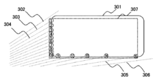
- Fig. 3 shows the case where the laser beam emitted from the high-resolution lidar211 hits the back and side surfaces of the vehicle 301 diagonally forward to the left, and each point cloud is numbered.
- the difference in the distance between the adjacent laser beams is larger than the set threshold value.
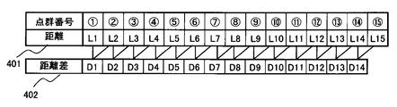
- the point group (1) hit by the laser beam 303 is regarded as the edge of the object, and the point group number (in this case (1)) is shown in the point group information management table of FIG. Store the distance L1 at the distance 401 in FIG.
- Fig. 4 explains with an example in which only the distance is stored, information on the horizontal and vertical angles of each point group may also be stored together.
- the next laser light 304 is a point cloud that hits the same object, and the point cloud information management table of FIG. 4 shows the distance L2 of the laser light 304 as a point cloud (2). Store in the location of. Similarly, if the distance difference from the next laser beam does not exceed the threshold value, the distance Ln of the point cloud (n) is added to the distance 401 of the point cloud information management table in FIG.
- the distance of the point cloud is added up to the laser light 305, but the laser light 306 does not hit the vehicle 301, and the distance difference from the laser light 305 exceeds the threshold value. Therefore, assuming that the laser beam 306 hits another object, the point cloud (15) hit by the laser beam 305 is set as the end of the object, and the point cloud (1) to the point cloud (15) in the point cloud information management table of FIG. 4 is set. ) Is managed as one and the same object, and it is a target point group for creating an circumscribing rectangle. The circumscribed rectangle 307 becomes the created circumscribed rectangle.
- the circumscribed rectangle 307 Since it becomes difficult to read the numbers if the circumscribed rectangle is superimposed on the circled numbers in the figure, the circumscribed rectangle 307 is written outside each circled number for convenience. Although there is a difference from the circumscribed rectangle 307, there is actually no difference from the position of the back or side surface of the vehicle 301 because the circumscribed rectangle 307 is located at the center point of each circled number.
- the laser light 303 is treated as one object.
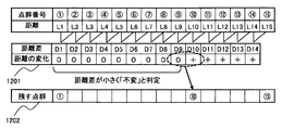
- the distance difference between the point group (1) and the point group (2) is defined as D1 and stored in the distance difference 402.
- the result of L (n + 1) -Ln is calculated as Dn
- the distance difference between adjacent point groups is calculated, and stored in the distance difference 402 in FIG.
- the point cloud in the middle part is reduced, and even if it is replaced with a short-circuit straight line, the effect on the shape of the circumscribing rectangle is small, so the point cloud is reduced.
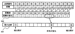
- the increase / decrease that is, the tendency of the change of the distance difference D1 to D14 calculated based on the distances L1 to L15 of each point cloud is obtained.
- the distance is shorter in the point group (2), so the sign of D1 is-(minus) and the distance is decreasing. Saves- (minus). This judgment is also made for D2 to D14, and the result is saved in the change of distance 502.
- the change in the distance between the point group (1) and the point group (10) gradually approaches the position where the laser beam hits, so the change in distance 502 becomes- (minus), but gradually.
- the change in distance 502 is + (plus).
- the point clouds that remain without being reduced are the point cloud (1), the point cloud (10), and the point cloud (15) as shown in the point cloud 501 that remains in FIG.
- the processor stores a straight line connecting one point left unreduced and the next point left unreduced. As a result, the shape of the object can be recognized with a small amount of data.
- the short-circuit straight line is used when the detected object is boxed and then the object is identified and the direction is specified based on the presence / absence of a linear component and its length and direction.
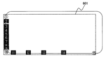
- Figure 6 shows the reduced point cloud in reverse display, and if you create an circumscribed rectangle with the remaining point clouds, it looks like the circumscribed rectangle 601. can get.
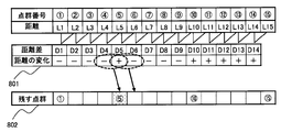
- the distance L5 of the point group (5) is shorter than the distance L4 of the point group (4), so D4 decreases (-) and the distance of the point group (6). Since L6 is longer than the distance L5 of the point group (5), D5 increases (+), and the distance L7 of the point group (7) is shorter than the distance L6 of the point group (6), so D6 decreases (-). It becomes a state of change like 801.
- the part where the change in distance changes from decrease (-) to increase (+) is considered to be an inflection point, and the detection position of the object is on the front side where the distance from lidar is short, so it is considered to be a protrusion. Be done. Therefore, the point cloud (5) between D4 and D5 is left, and the point cloud (5) is put in the remaining point cloud 802.
- the part where the change in distance changes from increase (+) to decrease (-) is also considered to be an inflection point.
- L6 is longer than L5
- L7 is shorter than L6
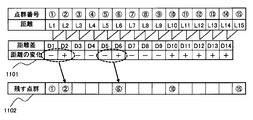
- the point cloud (6) is an inflection point, but it is shown to be inside the point cloud (5) that touches the extrinsic rectangle 702. It is not necessary to leave (6) because it is not related to creating the circumscribing rectangle 702.
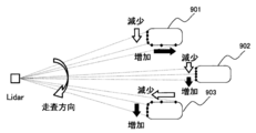
- vehicle 902 which is located in front and can detect only the back of the vehicle, it is not an inflection point, but the change in distance has changed from decreasing to increasing directly in front of the vehicle where the distance is the shortest. That is, if the horizontal scanning direction of the point cloud does not change, the change in distance changes from decrease to increase regardless of the positional relationship of the vehicle.
- the points between the point groups in the remaining point group 802 can be regarded as almost straight lines, the point group (1) and the point group (5), the point group (5) and the point group (10), and the point group (10) ) And the point group (15) are stored as a short-circuit straight line.
- the point cloud (5) with protrusions or the point cloud (10) with rounded corners is used as the end point, there may be a deviation from the actual straight line part, so connect the adjacent points to each other.
- the points between the point group (2) and the point group (4), the point group (6) and the point group (9), and the point group (11) and the point group (14) are stored as a short-circuit straight line. To do.
- the threshold value is set to a value larger than the distance difference between the point group (2) and the point group (3) but smaller than the distance difference between the point group (10) and the point group (11), the point group (3) in FIG.
- the value of the distance difference D1 to D9 from the point group (1) to the point group (10) is from the threshold (third threshold Th3). Since it is small and invariant (0), the result is as shown in the change of distance 1201 in FIG.
- the third threshold value Th3 is several centimeters, which is smaller than the first threshold value Th1 described later.
- the point cloud (10) remains by setting it as an inflection point not only when it changes from a decrease to an increase but also when it changes from an invariant to an increase, but it is also a target for reduction when the invariant continues as in the case of a continuous decrease.
- the point cloud (2) to the point cloud (9) are invariant when the amount of change is within the threshold range. It will be reduced.
- the remaining point groups are the point group (1) and the point group (1) at both ends. Only the point group (10) that becomes the change point is 15), and the extrinsic rectangle is the dotted line indicated by 1302.
- the circumscribed rectangle 1302 is determined to be farther or smaller than the circumscribed rectangle 1303 indicating the actual position and size of the vehicle, there is a risk of abnormally approaching or contacting the vehicle 1301.
- the point cloud is left, and the curved part is not short-circuited by one approximate straight line, but is connected by a plurality of approximate straight lines along the curved part. , Make sure that the outline of the object cannot be accurately grasped due to the continuous point cloud to be reduced more than necessary.
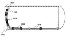
- FIG. 15 is a diagram in which the point clouds to be reduced are highlighted and distinguished.
- the point group (1) and the point group (5) are defined by the short-circuit straight line 1503 as shown in FIG. 5) and the point group (9) are connected by a short-circuit straight line 1504, the point group (10) and the point group (13) are connected by a short-circuit straight line 1505, and the point group (13) and the point group (15) are connected by a short-circuit straight line 1506. Save as a short-circuit straight line.
- the number of point clouds may be recounted from the point cloud.
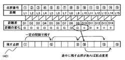
- the fourth point group (13) from the point group (9) is left, but since the point group (10) remains as a change point without being reduced, the point group (10) The fourth point cloud (14) is left and the point cloud (13) is reduced.
- the extrinsic rectangle is created including the point cloud (5), it becomes an extrinsic rectangle like the extrinsic rectangle 1501, and the outline of the actual vehicle does not protrude from the extrinsic rectangle 1501.
- the horizontal angle of the point group to be left may be changed so as to be narrower at a long distance.
- the point cloud may be left for each fixed number of point clouds even if the horizontal angle interval becomes non-uniform without adjusting the number.
- the horizontal angle of the point group left at a fixed interval or a fixed angle is changed according to each vertical angle so that the point group with the same horizontal angle does not remain continuously in the vertical direction, and the reduction is made.
- the point group to be formed may not be biased to a specific part.
- the amount of change at this time may be changed randomly within a certain range.
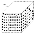
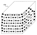
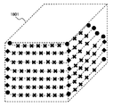
- the processor performs point cloud reduction processing not only for the arrangement of point clouds in one direction but also for the arrangement of point clouds in another direction.
- the point cloud can be reduced in two directions.
- the processing load of the point cloud can be further reduced.
- the two directions are orthogonal, but they do not have to be orthogonal.
- the position of the road surface with a height of 0 is set as the lower end of the box 1801 instead of the position of the point cloud detected at the lowest height. There is.
- the number of point clouds that can be reduced is small even if there are no point clouds that meet the conditions that can be reduced. Therefore, the effect of shortening the processing time is small, and the point cloud required for creating or boxing the circumscribing rectangle is lost, which increases the possibility of affecting the detection performance.
- the point cloud in is not reduced.
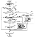
- the operation based on the flowchart of FIG. 19 is as follows.
- the main body of operation is, for example, a processor.
- Step 1901 Perform reduction processing for each point group in a loop of the number of point groups.
- Step 1902 Compare the distance of the point cloud with a predetermined threshold value (fifth threshold value Th5), and if it is far, the reduction process is not performed, and if it is close, the process proceeds to step 1903.
- a predetermined threshold value Th5
- the processor leaves the data of the second point (target point) without reducing it.
- the fifth threshold value Th5 is several tens of meters.
- the point distance is the distance (measured value) from the lidar (device for acquiring the point cloud) to the point.
- Step 1903 Compare the distance difference with the previous point cloud with a predetermined threshold value (first threshold value Th1), and if it is long, proceed to step 1904, and if it is short, proceed to step 1903_1.
- first threshold value Th1 a predetermined threshold value
- Step 1903_1 Compare the distance difference with the previous point cloud with a predetermined threshold value (second threshold value Th2), and if it is long, proceed to step 1904, and if it is short, proceed to step 1901.
- second threshold value Th2 a predetermined threshold value
- Step 1904 The previous point cloud is set as the end point of the previous object (object belonging to the previous group), and the target point group is set as the starting point of another object, and each is left without reduction.
- the processor sets the first point. It is determined that the second point belongs to different objects, and the data of the first point (previous point) and the second point (target point) at the boundary of each object are left without reduction (Ste 1904).
- the second threshold value Th2 is around 1 m. If the second threshold Th2 is too small, the same object is divided, and if the second threshold Th2 is too large, the target object is combined with another object.
- Step 1905 Compare the angle difference or distance difference with the most recent unreduced point cloud with a predetermined threshold (4th threshold Th4), and if it is above the threshold, proceed to step 1906, and if it is below the threshold, proceed to step 1906. Proceed to step 1907.
- the processor first Leave the data for point 2 unreduced (step 1906).
- the fourth threshold value Th4 is several degrees when specified by an angle, and several tens of cm when specified by a distance.
- Step 1906 The target point cloud is not reduced, the short-circuit straight line portion is determined as the end point of the short-circuit straight line, and the start point of the next short-circuit straight line is set.
- Step 1907 If the pattern of increase / decrease in the distance difference from the previous point cloud and the previous distance difference satisfies the condition of leaving the point cloud, proceed to step 1906, and if the condition of reducing the point cloud is satisfied, step 1908. Proceed to. Specifically, when the increase / decrease changes (for example, from ⁇ to +), the process proceeds to step 1906, and when the same tendency, that is, when the increase / decrease does not change (for example, ⁇ continues), the process proceeds to step 1908.
- the processor has a sign of a first distance change that indicates the difference between the distance of the second point and the distance of the first point, and a third that is next to the second point and constitutes a point group. If the second distance change amount, which indicates the difference between the point distance and the second point distance, has a different sign (step 1907: YES), the data at the second point is left unreduced (step 1906).
- the processor considers the first distance change amount to be 0 when the first distance change amount is smaller than the third threshold value, and the second distance change amount is If it is smaller than the third threshold value, the second distance change amount is regarded as 0, and the code state (+,-, or 0) with respect to the first distance change amount and the code state (+,-, or 0) with respect to the second distance change amount ( If +,-, or 0) are different, the data at the second point may be left unreduced.
- Step 1908 Reduce the target point cloud.
- step 1902 there are four conditions for reducing the target points (steps 1902, 1903, 1905, 1907), but one or more conditions may be deleted.
- the difference between the distance of the first point (previous point) that constitutes the point cloud and the distance of the second point (target point) that is next to the first point and constitutes the point cloud is If it is smaller than the threshold (first threshold Th1) (step 1903: short), the data of the second point may be reduced from the data of the point cloud (step 1908).
- the memory storage device stores data of a point cloud of an object.
- the first threshold value Th1 is several to ten and several centimeters.
- the purpose of reducing the point cloud is to reduce the total amount of processing including recognition processing, and even if there are some point clouds that cannot be reduced, rather than reducing as many points as possible without missing the point clouds that can be reduced. Perform point cloud reduction processing by a method with a low processing load for point cloud reduction.
- the distance to the point group is used as the threshold value instead of the number of point groups, and some or all the point groups that hit the object are used. If is farther than the distance of the threshold value, the point group reduction process may not be performed.
- the above point cloud reduction process is performed at the polar coordinate system stage in order to reduce the number of point cloud data for which conversion processing is executed to the Cartesian (XYZ) coordinate system.
- the point cloud may be reduced after the conversion to the system.
- the point cloud data is reduced in each of the X-axis and Y-axis directions, and the point cloud targeted for reduction is reduced on both or one of the points.
- the point cloud is based on the information on the number, position and size of the object detected in the previous frame, and the reduced number of point clouds.
- a process of reducing the point cloud within a certain range or on average is performed.
- the processor is constant when the number of unreduced points remaining in the point cloud exceeds or is expected to exceed a predetermined threshold (th6th threshold Th6).
- the data of the point cloud included in the region may be reduced.
- the sixth threshold value Th6 is tens of thousands to hundreds of thousands, and is the target maximum value of the remaining point group (the number of point groups that can be processed within the specified time).
- the point cloud can be reduced to some extent.
- the number of point clouds is reduced by reducing all or part of the point cloud from a predetermined range near the edge of the viewing angle.
- it is a point cloud in a certain range on both sides in the horizontal direction as in regions 2001 and 2002 in FIG. 20A, or in a certain range above and below in the vertical direction as in regions 2003 and 2004 in FIG. 20B. Try to reduce the point cloud.
- the range to be reduced is set in advance for each, but the range may be increased or decreased according to the target value of the reduction amount of the point cloud.
- area 2001 and area 2002 have the same width (viewing angle), but they are on the right side so as to reduce the hindrance to detection of the road on the oncoming lane side and structures near the road.
- the range of region 2002 may be reduced. However, if you are driving in the right lane of a road with multiple lanes separated by a median strip, it is better to reduce the range of the left area 2001 so that the influence of detection on the left lane side is reduced. ,
- the range may be changed sequentially according to the road and driving conditions.
- the area 2003 and the area 2004 have the same width (viewing angle), but the range of the lower area 2004 may be reduced with an emphasis on the road surface condition.
- the target is the laser beam irradiated in the range passing through the area 2001 to 2004, and the object is displayed before and after the illustrated part. Including the case of hitting.
- the left half of the overlapping area 2105 may reduce the point cloud of Lidar2102, and the right half may reduce the point cloud of Lidar2101.
- each lidar may be reduced every other one, and half of the point clouds may be thinned out so that the point cloud density is equivalent to the non-overlapping area.
- the laser beam arriving farther than the regions 2003 to 2005 is also targeted, and the region farther than the illustrated portion is also included.
- the number of nearby objects is small, the number of objects that need to update the position and size of the objects and the tracking process of moving objects is small, and the processing load in the subsequent stage after recognition is low, it is constant. It is not necessary to reduce the point cloud in the range or on average.
- the reduction method and the amount of reduction in the next cycle may be controlled from the number of point groups reduced and the number of point groups reduced within a certain range or on average.
- the real-time property may be maintained by processing as much as possible within the time of one cycle in order from the object closest to the own vehicle.
- the processing load of the point cloud can be suppressed even if the device for acquiring the point cloud of the object has a higher resolution and the number of points constituting the point cloud increases. ..
- the present invention is not limited to the above-described examples, and includes various modifications.
- the above-described examples have been described in detail in order to explain the present invention in an easy-to-understand manner, and are not necessarily limited to those having all the described configurations.
- it is possible to replace a part of the configuration of one embodiment with the configuration of another embodiment and it is also possible to add the configuration of another embodiment to the configuration of one embodiment.
- Lidar is adopted as a device for acquiring a point cloud of an object with light, but a device for acquiring a point cloud with radio waves may be used. That is, the means for acquiring the point cloud does not matter.
- each of the above configurations, functions, etc. may be realized by hardware, for example, by designing a part or all of them with an integrated circuit. Further, each of the above configurations, functions, and the like may be realized by software by the processor (microcomputer) interpreting and executing a program that realizes each function. Information such as programs, tables, and files that realize each function can be stored in a memory, a hard disk, a recording device such as an SSD (Solid State Drive), or a recording medium such as an IC card, an SD card, or a DVD.
- a memory a hard disk
- a recording device such as an SSD (Solid State Drive)
- a recording medium such as an IC card, an SD card, or a DVD.
- the embodiment of the present invention may have the following aspects.
- the purpose is to leave the point group of the characteristic position necessary for specifying the position and size of the object without reducing it, and to reduce the part where multiple point groups in the middle of the straight line part are connected. By reducing the number of point group data and approximating the end points of the straight line with a short-circuited straight line, the information necessary for grasping the position, size and shape of the object remains, so that the object can be detected.
- the purpose is to maintain the recognition performance, reduce the number of point group data, reduce the processing load, that is, speed up the processing.
- the distance change amount 1 between the point group data and the neighboring point (next point) of the point group data and the distance change amount 2 between the next point and the neighboring point (next next point) are set.
- the state of increase or decrease changes between the distance change amount 1 and the distance change amount 2 a reduction method and a processing device that do not reduce the point group.
- the total number of point cloud data can be reduced without degrading the object detection performance, and the points can be reduced.
- the time required for group data processing it is possible to suppress an increase in the processing load even if the lidar becomes high resolution and the number of output point clouds increases.
- Recessed External rectangle when there is a protruding part 1501... External rectangular when there is a curved part, 1502... External rectangle when the curved part protrudes, 1503... Short-circuit straight line connecting the point cloud (1) and the point cloud (5) , 1504 ... Short-circuit straight line connecting point cloud (5) and point cloud (9), 1505 ... Short-circuit straight line connecting point cloud (10) and point cloud (13), 1506 ... Point cloud (13) and point cloud (15) Short-circuit straight line connecting, 2001, 2002, 2003, 2004 ... Area to reduce point cloud, 2105 ... Overlapping area of two lidar detections
Landscapes
- Engineering & Computer Science (AREA)
- Physics & Mathematics (AREA)
- Computer Networks & Wireless Communication (AREA)
- General Physics & Mathematics (AREA)
- Radar, Positioning & Navigation (AREA)
- Remote Sensing (AREA)
- Electromagnetism (AREA)
- Optical Radar Systems And Details Thereof (AREA)
- Traffic Control Systems (AREA)
Abstract
Description
具体的に図4の点群の並びの場合の例で説明すると、まず両端にある点、すなわち点群(1)と点群(15)は削減しないで残すので、図5の残す点群501に保存する。
図7のように車両701の背面の一部で点群(5)のように突起状に飛び出ている場合は、外接矩形702のように囲む必要があるが、点群(5)の前後の距離差が閾値より小さいと点群(5)が削減対象になり、外接矩形703のように囲まれ、突起部分が枠外となってしまい車両701の位置やサイズを誤認識し衝突や接触をするおそれがある。
そこで、D4とD5の間の点群(5)は残し、残す点群802に点群(5)を入れる。
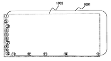
次に、図10のように車両1001の背面の点群(3)と点群(7)の部分が凹んでいる場合の処理方法について説明する。
このように、車両1001の背面の点群が一直線上に並んでおらず凹凸があると、凹みの部分でも変曲点と判断され、点群が削減されずに残ってしまう場合がある。
これまでの例では、車両背面がほぼ直線に近い場合で説明をしてきたが、図13の車両1301のように変化量が小さく徐々に形状が変化する緩く湾曲している場合がある。
一定の角度毎に点群を残す場合、水平方向の点群が等間隔に送出されている場合は一定の点群数毎に点群を残せば一定間隔で残すことになるので、例えば4点毎に残す場合、図14の残す点群1401のように点群(5)、点群(9)および点群(13)を残す。
また、ある水平方向の一層分の点群の並びの削減だけではなく、垂直方向に重なる各層の上下の点群の並びに対して、水平方向と同様な点群削減処理を行うこともできる。
その結果、点群の処理負荷をさらに低減することができる。なお、本実施例では、2方向は直交するが直交しなくてもよい。
図19のフローチャートに基づく動作は以下の通りである。なお、動作の主体は、例えばプロセッサである。
点群の削減は認識処理などを含めた全体の処理量の低減が目的であり、削減可能な点群を欠かすことなく一点でも多く削減するよりも、一部に削減されない点群があっても点群削減のための処理負荷が低い方法で点群削減処理を行う。
例えば、上述した実施例は本発明を分かりやすく説明するために詳細に説明したものであり、必ずしも説明した全ての構成を備えるものに限定されるものではない。また、ある実施例の構成の一部を他の実施例の構成に置き換えることが可能であり、また、ある実施例の構成に他の実施例の構成を加えることも可能である。また、各実施例の構成の一部について、他の構成の追加・削除・置換をすることが可能である。
Claims (10)
- 物体の点群のデータを記憶する記憶装置と、
前記点群を構成する第1の点の距離と、前記第1の点の隣にあって前記点群を構成する第2の点の距離との差が第1閾値より小さい場合、前記点群のデータから前記第2の点のデータを削減するプロセッサと、
を備えることを特徴とする処理装置。 - 請求項1に記載の処理装置において、
前記プロセッサは、
前記第1の点の距離と前記第2の点の距離との差が、第2閾値より大きい場合、前記第1の点と前記第2の点は互いに異なる物体にそれぞれ属していると判定し、それぞれの物体の境界にある前記第1の点と前記第2の点のデータを削減せずに残すことを特徴とする処理装置。 - 請求項1に記載の処理装置において、
前記プロセッサは、
前記第2の点の距離と前記第1の点の距離との差分を示す第1の距離変化量の符号と、前記第2の点の隣にあって前記点群を構成する第3の点の距離と前記第2の点の距離との差分を示す第2の距離変化量の符号が異なる場合、前記第2の点のデータを削減せずに残すことを特徴とする処理装置。 - 請求項3に記載の処理装置において、
前記プロセッサは、
前記第1の距離変化量が第3の閾値より小さい場合、前記第1の距離変化量を0とみなし、かつ、前記第2の距離変化量が前記第3の閾値より小さい場合、前記第2の距離変化量を0とみなし、
前記第1の距離変化量に対する符号の状態と、前記第2の距離変化量に対する符号の状態が異なる場合、前記第2の点のデータを削減せずに残すことを特徴とする処理装置。 - 請求項1に記載の処理装置において、
前記プロセッサは、
前記第1の点と前記第2の点との間の角度差又は距離差が第4閾値以上である場合、前記第2の点のデータを削減せずに残すことを特徴とする処理装置。 - 請求項1に記載の処理装置において、
前記プロセッサは、
前記第2の点の距離が第5閾値より大きい場合、前記第2の点のデータを削減せずに残すことを特徴とする処理装置。 - 請求項1に記載の処理装置において、
前記プロセッサは、
前記点群を構成する点のうち削減されずに残された点の数が第6閾値を超えた場合もしくは超えることが予測される場合、一定の領域に含まれる点群のデータを削減することを特徴とする処理装置。 - 請求項1に記載の処理装置において、
前記プロセッサは、
削減されずに残された1つの点と、削減されずに残されたその次の点とを接続する直線を保存することを特徴とする処理装置。 - 請求項1に記載の処理装置において、
前記プロセッサは、
一方向の前記点群の並びだけではなく、別の方向の前記点群の並びに対しても前記点群の削減処理を行うことを特徴とする処理装置。 - 物体の点群のデータを記憶する工程と、
前記点群を構成する第1の点の距離と、前記第1の点の隣にあって前記点群を構成する第2の点の距離との差が第1閾値より小さい場合、前記点群のデータから前記第2の点のデータを削減する工程と、
を処理装置に実行させることを特徴とする点群削減方法。
Priority Applications (2)
| Application Number | Priority Date | Filing Date | Title |
|---|---|---|---|
| US17/788,579 US12292508B2 (en) | 2019-10-01 | 2020-09-08 | Processing apparatus and point cloud elimination method |
| JP2021550512A JP7265027B2 (ja) | 2019-10-01 | 2020-09-08 | 処理装置及び点群削減方法 |
Applications Claiming Priority (2)
| Application Number | Priority Date | Filing Date | Title |
|---|---|---|---|
| JP2019-181145 | 2019-10-01 | ||
| JP2019181145 | 2019-10-01 |
Publications (1)
| Publication Number | Publication Date |
|---|---|
| WO2021065371A1 true WO2021065371A1 (ja) | 2021-04-08 |
Family
ID=75337162
Family Applications (1)
| Application Number | Title | Priority Date | Filing Date |
|---|---|---|---|
| PCT/JP2020/033882 Ceased WO2021065371A1 (ja) | 2019-10-01 | 2020-09-08 | 処理装置及び点群削減方法 |
Country Status (3)
| Country | Link |
|---|---|
| US (1) | US12292508B2 (ja) |
| JP (1) | JP7265027B2 (ja) |
| WO (1) | WO2021065371A1 (ja) |
Cited By (6)
| Publication number | Priority date | Publication date | Assignee | Title |
|---|---|---|---|---|
| CN114491444A (zh) * | 2022-01-20 | 2022-05-13 | 支付宝(杭州)信息技术有限公司 | 身份识别方法、装置及设备 |
| WO2023026875A1 (ja) * | 2021-08-26 | 2023-03-02 | 株式会社デンソー | 物体認識装置 |
| JPWO2023127353A1 (ja) * | 2021-12-28 | 2023-07-06 | ||
| JP2023174272A (ja) * | 2022-05-27 | 2023-12-07 | 日産自動車株式会社 | 物体認識方法及び物体認識装置 |
| JP2024042920A (ja) * | 2022-09-16 | 2024-03-29 | 日本電気株式会社 | 光センシングシステム、光センシング装置、及び、光センシング方法 |
| JP2025110145A (ja) * | 2024-01-15 | 2025-07-28 | 日本電気株式会社 | 測定装置、測定方法及びプログラム |
Families Citing this family (3)
| Publication number | Priority date | Publication date | Assignee | Title |
|---|---|---|---|---|
| US12195047B2 (en) * | 2021-08-18 | 2025-01-14 | Zoox, Inc. | Determining object characteristics using unobstructed sensor emissions |
| US12485881B2 (en) | 2021-08-18 | 2025-12-02 | Zoox, Inc. | Determining occupancy using unobstructed sensor emissions |
| US20240402309A1 (en) * | 2023-05-31 | 2024-12-05 | Compertum Microsystems Inc. | Light Detection and Ranging Apparatus and Event Detection Method Thereof |
Citations (5)
| Publication number | Priority date | Publication date | Assignee | Title |
|---|---|---|---|---|
| JP2002005649A (ja) * | 2000-06-20 | 2002-01-09 | Asahi Optical Co Ltd | 点群データ処理装置、点群データ処理方法および点群データ処理プログラムを格納した記録媒体 |
| US20130028482A1 (en) * | 2011-07-29 | 2013-01-31 | Raytheon Company | Method and System for Thinning a Point Cloud |
| US10210669B1 (en) * | 2016-06-03 | 2019-02-19 | The United States Of America As Represented By The Scretary Of The Navy | Method for 3D object, environment model, and documentation generation using scan point clouds and digital object libraries |
| JP2019057918A (ja) * | 2018-11-02 | 2019-04-11 | キヤノン株式会社 | 生成装置および生成方法、プログラム |
| CN109934637A (zh) * | 2019-03-20 | 2019-06-25 | 合肥浮点信息科技有限公司 | 一种基于互联网的一卡通支付分析系统 |
Family Cites Families (6)
| Publication number | Priority date | Publication date | Assignee | Title |
|---|---|---|---|---|
| US10545029B2 (en) * | 2016-12-30 | 2020-01-28 | DeepMap Inc. | Lane network construction using high definition maps for autonomous vehicles |
| JP7032062B2 (ja) | 2017-06-02 | 2022-03-08 | 株式会社Ihi | 点群データ処理装置、移動ロボット、移動ロボットシステム、および点群データ処理方法 |
| JP6433559B1 (ja) | 2017-09-19 | 2018-12-05 | キヤノン株式会社 | 提供装置および提供方法、プログラム |
| US11430145B2 (en) * | 2018-06-17 | 2022-08-30 | Foresight Ai Inc. | Identification of local motions in point cloud data |
| US10346998B1 (en) * | 2019-02-25 | 2019-07-09 | Nurulize, Inc. | Method of merging point clouds that identifies and retains preferred points |
| US11662469B2 (en) * | 2019-04-04 | 2023-05-30 | Denso International America, Inc. | System and method for merging clusters |
-
2020
- 2020-09-08 WO PCT/JP2020/033882 patent/WO2021065371A1/ja not_active Ceased
- 2020-09-08 US US17/788,579 patent/US12292508B2/en active Active
- 2020-09-08 JP JP2021550512A patent/JP7265027B2/ja active Active
Patent Citations (5)
| Publication number | Priority date | Publication date | Assignee | Title |
|---|---|---|---|---|
| JP2002005649A (ja) * | 2000-06-20 | 2002-01-09 | Asahi Optical Co Ltd | 点群データ処理装置、点群データ処理方法および点群データ処理プログラムを格納した記録媒体 |
| US20130028482A1 (en) * | 2011-07-29 | 2013-01-31 | Raytheon Company | Method and System for Thinning a Point Cloud |
| US10210669B1 (en) * | 2016-06-03 | 2019-02-19 | The United States Of America As Represented By The Scretary Of The Navy | Method for 3D object, environment model, and documentation generation using scan point clouds and digital object libraries |
| JP2019057918A (ja) * | 2018-11-02 | 2019-04-11 | キヤノン株式会社 | 生成装置および生成方法、プログラム |
| CN109934637A (zh) * | 2019-03-20 | 2019-06-25 | 合肥浮点信息科技有限公司 | 一种基于互联网的一卡通支付分析系统 |
Cited By (12)
| Publication number | Priority date | Publication date | Assignee | Title |
|---|---|---|---|---|
| WO2023026875A1 (ja) * | 2021-08-26 | 2023-03-02 | 株式会社デンソー | 物体認識装置 |
| JP2023032080A (ja) * | 2021-08-26 | 2023-03-09 | 株式会社デンソー | 物体認識装置 |
| JP7506643B2 (ja) | 2021-08-26 | 2024-06-26 | 株式会社デンソー | 物体認識装置、及びプログラム |
| JPWO2023127353A1 (ja) * | 2021-12-28 | 2023-07-06 | ||
| JP7745653B2 (ja) | 2021-12-28 | 2025-09-29 | 株式会社クボタ | 農業機械、センシングシステム、センシング方法、遠隔操縦システム、および制御方法 |
| US12685241B2 (en) | 2021-12-28 | 2026-07-21 | Kubota Corporation | Agricultural machine, sensing system, sensing method, remote operation system, and control method |
| CN114491444A (zh) * | 2022-01-20 | 2022-05-13 | 支付宝(杭州)信息技术有限公司 | 身份识别方法、装置及设备 |
| JP2023174272A (ja) * | 2022-05-27 | 2023-12-07 | 日産自動車株式会社 | 物体認識方法及び物体認識装置 |
| JP7803214B2 (ja) | 2022-05-27 | 2026-01-21 | 日産自動車株式会社 | 物体認識方法及び物体認識装置 |
| JP2024042920A (ja) * | 2022-09-16 | 2024-03-29 | 日本電気株式会社 | 光センシングシステム、光センシング装置、及び、光センシング方法 |
| JP2025110145A (ja) * | 2024-01-15 | 2025-07-28 | 日本電気株式会社 | 測定装置、測定方法及びプログラム |
| JP7736093B2 (ja) | 2024-01-15 | 2025-09-09 | 日本電気株式会社 | 測定装置、測定方法及びプログラム |
Also Published As
| Publication number | Publication date |
|---|---|
| US12292508B2 (en) | 2025-05-06 |
| JPWO2021065371A1 (ja) | 2021-04-08 |
| JP7265027B2 (ja) | 2023-04-25 |
| US20230034208A1 (en) | 2023-02-02 |
Similar Documents
| Publication | Publication Date | Title |
|---|---|---|
| JP7265027B2 (ja) | 処理装置及び点群削減方法 | |
| CN110850859B (zh) | 一种机器人及其避障方法和避障系统 | |
| CN110632617B (zh) | 一种激光雷达点云数据处理的方法及装置 | |
| US10871776B2 (en) | Method for identifying objects in a traffic space | |
| WO2022001322A1 (zh) | 一种车辆控制方法、装置、电子设备及存储介质 | |
| EP4099060B1 (en) | Object recognition method and object recognition device | |
| CN114529539B (zh) | 无人设备路面障碍检测方法、装置、无人设备及存储介质 | |
| US10748014B2 (en) | Processing device, object recognition apparatus, device control system, processing method, and computer-readable recording medium | |
| CN115331189B (zh) | 一种车辆可通行区域检测方法、系统和存储介质 | |
| CN110119751B (zh) | 激光雷达点云目标分割方法、目标匹配方法、装置及车辆 | |
| EP4009228A1 (en) | Method for determining a semantic free space | |
| CN113625296A (zh) | 基于反光板的机器人定位方法、装置及机器人 | |
| CN115704908A (zh) | 利用激光雷达传感器的对象检测方法和对象跟踪装置 | |
| CN110815202A (zh) | 障碍物检测方法及装置 | |
| CN117372985A (zh) | 可行驶区域检测方法、装置、设备及存储介质 | |
| CN119716901A (zh) | 一种基于激光雷达感知的斗轮机防撞方法及其系统 | |
| JP2022065347A (ja) | 障害物検知装置 | |
| WO2023065313A1 (zh) | 遮挡关系判断方法、装置、存储介质及电子设备 | |
| US20260063770A1 (en) | Lidar control method and apparatus, terminal device, and storage medium | |
| WO2024197519A1 (zh) | 一种点云评估方法及装置 | |
| JP7315723B2 (ja) | 車両姿勢認識方法及び関連装置 | |
| CN117876999A (zh) | 通用障碍物检测方法、可读存储介质及智能设备 | |
| CN110737276A (zh) | 预警方法、巡逻机器人及计算机可读存储介质 | |
| CN116721404A (zh) | 车辆目标碰撞点的选取方法、装置、终端及存储介质 | |
| KR20210114792A (ko) | 라이다 센서 기반의 객체 추적 장치 및 그 방법 |
Legal Events
| Date | Code | Title | Description |
|---|---|---|---|
| 121 | Ep: the epo has been informed by wipo that ep was designated in this application |
Ref document number: 20872398 Country of ref document: EP Kind code of ref document: A1 |
|
| NENP | Non-entry into the national phase |
Ref country code: DE |
|
| ENP | Entry into the national phase |
Ref document number: 2021550512 Country of ref document: JP Kind code of ref document: A |
|
| 122 | Ep: pct application non-entry in european phase |
Ref document number: 20872398 Country of ref document: EP Kind code of ref document: A1 |
|
| WWG | Wipo information: grant in national office |
Ref document number: 17788579 Country of ref document: US |