WO2021060419A1 - Production method of catalyst support and production method of fibrous carbon nanostructure - Google Patents
Production method of catalyst support and production method of fibrous carbon nanostructure Download PDFInfo
- Publication number
- WO2021060419A1 WO2021060419A1 PCT/JP2020/036140 JP2020036140W WO2021060419A1 WO 2021060419 A1 WO2021060419 A1 WO 2021060419A1 JP 2020036140 W JP2020036140 W JP 2020036140W WO 2021060419 A1 WO2021060419 A1 WO 2021060419A1
- Authority
- WO
- WIPO (PCT)
- Prior art keywords
- catalyst
- producing
- carrier
- particulate carrier
- catalyst carrier
- Prior art date
Links
Images


Classifications
-
- B—PERFORMING OPERATIONS; TRANSPORTING
- B01—PHYSICAL OR CHEMICAL PROCESSES OR APPARATUS IN GENERAL
- B01J—CHEMICAL OR PHYSICAL PROCESSES, e.g. CATALYSIS OR COLLOID CHEMISTRY; THEIR RELEVANT APPARATUS
- B01J2/00—Processes or devices for granulating materials, e.g. fertilisers in general; Rendering particulate materials free flowing in general, e.g. making them hydrophobic
- B01J2/14—Processes or devices for granulating materials, e.g. fertilisers in general; Rendering particulate materials free flowing in general, e.g. making them hydrophobic in rotating dishes or pans
-
- B—PERFORMING OPERATIONS; TRANSPORTING
- B01—PHYSICAL OR CHEMICAL PROCESSES OR APPARATUS IN GENERAL
- B01J—CHEMICAL OR PHYSICAL PROCESSES, e.g. CATALYSIS OR COLLOID CHEMISTRY; THEIR RELEVANT APPARATUS
- B01J23/00—Catalysts comprising metals or metal oxides or hydroxides, not provided for in group B01J21/00
- B01J23/002—Mixed oxides other than spinels, e.g. perovskite
-
- B—PERFORMING OPERATIONS; TRANSPORTING
- B01—PHYSICAL OR CHEMICAL PROCESSES OR APPARATUS IN GENERAL
- B01J—CHEMICAL OR PHYSICAL PROCESSES, e.g. CATALYSIS OR COLLOID CHEMISTRY; THEIR RELEVANT APPARATUS
- B01J21/00—Catalysts comprising the elements, oxides, or hydroxides of magnesium, boron, aluminium, carbon, silicon, titanium, zirconium, or hafnium
- B01J21/02—Boron or aluminium; Oxides or hydroxides thereof
- B01J21/04—Alumina
-
- B—PERFORMING OPERATIONS; TRANSPORTING
- B01—PHYSICAL OR CHEMICAL PROCESSES OR APPARATUS IN GENERAL
- B01J—CHEMICAL OR PHYSICAL PROCESSES, e.g. CATALYSIS OR COLLOID CHEMISTRY; THEIR RELEVANT APPARATUS
- B01J2/00—Processes or devices for granulating materials, e.g. fertilisers in general; Rendering particulate materials free flowing in general, e.g. making them hydrophobic
- B01J2/006—Coating of the granules without description of the process or the device by which the granules are obtained
-
- B—PERFORMING OPERATIONS; TRANSPORTING
- B01—PHYSICAL OR CHEMICAL PROCESSES OR APPARATUS IN GENERAL
- B01J—CHEMICAL OR PHYSICAL PROCESSES, e.g. CATALYSIS OR COLLOID CHEMISTRY; THEIR RELEVANT APPARATUS
- B01J2/00—Processes or devices for granulating materials, e.g. fertilisers in general; Rendering particulate materials free flowing in general, e.g. making them hydrophobic
- B01J2/12—Processes or devices for granulating materials, e.g. fertilisers in general; Rendering particulate materials free flowing in general, e.g. making them hydrophobic in rotating drums
-
- B—PERFORMING OPERATIONS; TRANSPORTING
- B01—PHYSICAL OR CHEMICAL PROCESSES OR APPARATUS IN GENERAL
- B01J—CHEMICAL OR PHYSICAL PROCESSES, e.g. CATALYSIS OR COLLOID CHEMISTRY; THEIR RELEVANT APPARATUS
- B01J21/00—Catalysts comprising the elements, oxides, or hydroxides of magnesium, boron, aluminium, carbon, silicon, titanium, zirconium, or hafnium
- B01J21/06—Silicon, titanium, zirconium or hafnium; Oxides or hydroxides thereof
- B01J21/066—Zirconium or hafnium; Oxides or hydroxides thereof
-
- B—PERFORMING OPERATIONS; TRANSPORTING
- B01—PHYSICAL OR CHEMICAL PROCESSES OR APPARATUS IN GENERAL
- B01J—CHEMICAL OR PHYSICAL PROCESSES, e.g. CATALYSIS OR COLLOID CHEMISTRY; THEIR RELEVANT APPARATUS
- B01J23/00—Catalysts comprising metals or metal oxides or hydroxides, not provided for in group B01J21/00
- B01J23/70—Catalysts comprising metals or metal oxides or hydroxides, not provided for in group B01J21/00 of the iron group metals or copper
- B01J23/74—Iron group metals
- B01J23/745—Iron
-
- B—PERFORMING OPERATIONS; TRANSPORTING
- B01—PHYSICAL OR CHEMICAL PROCESSES OR APPARATUS IN GENERAL
- B01J—CHEMICAL OR PHYSICAL PROCESSES, e.g. CATALYSIS OR COLLOID CHEMISTRY; THEIR RELEVANT APPARATUS
- B01J37/00—Processes, in general, for preparing catalysts; Processes, in general, for activation of catalysts
- B01J37/02—Impregnation, coating or precipitation
- B01J37/0215—Coating
- B01J37/0221—Coating of particles
- B01J37/0223—Coating of particles by rotation
-
- B—PERFORMING OPERATIONS; TRANSPORTING
- B01—PHYSICAL OR CHEMICAL PROCESSES OR APPARATUS IN GENERAL
- B01J—CHEMICAL OR PHYSICAL PROCESSES, e.g. CATALYSIS OR COLLOID CHEMISTRY; THEIR RELEVANT APPARATUS
- B01J37/00—Processes, in general, for preparing catalysts; Processes, in general, for activation of catalysts
- B01J37/02—Impregnation, coating or precipitation
- B01J37/0215—Coating
- B01J37/0228—Coating in several steps
-
- B—PERFORMING OPERATIONS; TRANSPORTING
- B01—PHYSICAL OR CHEMICAL PROCESSES OR APPARATUS IN GENERAL
- B01J—CHEMICAL OR PHYSICAL PROCESSES, e.g. CATALYSIS OR COLLOID CHEMISTRY; THEIR RELEVANT APPARATUS
- B01J37/00—Processes, in general, for preparing catalysts; Processes, in general, for activation of catalysts
- B01J37/02—Impregnation, coating or precipitation
- B01J37/0236—Drying, e.g. preparing a suspension, adding a soluble salt and drying
-
- B—PERFORMING OPERATIONS; TRANSPORTING
- B01—PHYSICAL OR CHEMICAL PROCESSES OR APPARATUS IN GENERAL
- B01J—CHEMICAL OR PHYSICAL PROCESSES, e.g. CATALYSIS OR COLLOID CHEMISTRY; THEIR RELEVANT APPARATUS
- B01J37/00—Processes, in general, for preparing catalysts; Processes, in general, for activation of catalysts
- B01J37/08—Heat treatment
- B01J37/082—Decomposition and pyrolysis
-
- C—CHEMISTRY; METALLURGY
- C01—INORGANIC CHEMISTRY
- C01B—NON-METALLIC ELEMENTS; COMPOUNDS THEREOF; METALLOIDS OR COMPOUNDS THEREOF NOT COVERED BY SUBCLASS C01C
- C01B32/00—Carbon; Compounds thereof
- C01B32/15—Nano-sized carbon materials
- C01B32/158—Carbon nanotubes
- C01B32/16—Preparation
- C01B32/162—Preparation characterised by catalysts
-
- D—TEXTILES; PAPER
- D01—NATURAL OR MAN-MADE THREADS OR FIBRES; SPINNING
- D01F—CHEMICAL FEATURES IN THE MANUFACTURE OF ARTIFICIAL FILAMENTS, THREADS, FIBRES, BRISTLES OR RIBBONS; APPARATUS SPECIALLY ADAPTED FOR THE MANUFACTURE OF CARBON FILAMENTS
- D01F9/00—Artificial filaments or the like of other substances; Manufacture thereof; Apparatus specially adapted for the manufacture of carbon filaments
- D01F9/08—Artificial filaments or the like of other substances; Manufacture thereof; Apparatus specially adapted for the manufacture of carbon filaments of inorganic material
- D01F9/12—Carbon filaments; Apparatus specially adapted for the manufacture thereof
- D01F9/127—Carbon filaments; Apparatus specially adapted for the manufacture thereof by thermal decomposition of hydrocarbon gases or vapours or other carbon-containing compounds in the form of gas or vapour, e.g. carbon monoxide, alcohols
- D01F9/1273—Alkenes, alkynes
-
- D—TEXTILES; PAPER
- D01—NATURAL OR MAN-MADE THREADS OR FIBRES; SPINNING
- D01F—CHEMICAL FEATURES IN THE MANUFACTURE OF ARTIFICIAL FILAMENTS, THREADS, FIBRES, BRISTLES OR RIBBONS; APPARATUS SPECIALLY ADAPTED FOR THE MANUFACTURE OF CARBON FILAMENTS
- D01F9/00—Artificial filaments or the like of other substances; Manufacture thereof; Apparatus specially adapted for the manufacture of carbon filaments
- D01F9/08—Artificial filaments or the like of other substances; Manufacture thereof; Apparatus specially adapted for the manufacture of carbon filaments of inorganic material
- D01F9/12—Carbon filaments; Apparatus specially adapted for the manufacture thereof
- D01F9/127—Carbon filaments; Apparatus specially adapted for the manufacture thereof by thermal decomposition of hydrocarbon gases or vapours or other carbon-containing compounds in the form of gas or vapour, e.g. carbon monoxide, alcohols
Definitions
- the present invention relates to a method for producing a catalyst carrier and a method for producing a fibrous carbon nanostructure.
- Fibrous carbon nanostructures such as carbon nanotubes (sometimes referred to as "CNTs"; see, for example, Non-Patent Document 1) have mechanical strength, sliding properties, flexibility, semiconducting and metallic conductivity. Since it has excellent various properties such as thermal conductivity and high chemical stability, it is being applied to a wide range of applications. Therefore, in recent years, a method for efficiently producing a fibrous carbon nanostructure having such excellent properties at low cost has been studied.
- the CVD method is a manufacturing method that has been studied many times as a method suitable for mass synthesis, continuous synthesis, and high-purity synthesis of single-walled carbon nanotubes having excellent characteristics (see, for example, Non-Patent Document 2). ).
- a supporting substrate is provided by circulating a raw material gas composed of acetylene, carbon dioxide, and an inert gas at a predetermined partial pressure on the surface of a supporting substrate carrying a catalyst containing Fe or the like.
- a technique for synthesizing carbon nanotubes is disclosed above.
- Patent Document 2 describes carbon nanofibers using a particulate carrier in which a catalyst layer is formed on the surface of a particulate carrier in a fluidized bed type or kiln type carrier body and a catalyst layer is formed on the surface.
- a fluidized bed reaction method for carrying out a growth reaction is disclosed.
- a dry method of spraying a catalyst raw material gas on the surface of the particulate carrier or a catalyst solution on the surface of the particulate carrier there is a wet method of coating, but the wet method is said to be superior to the dry method in that the catalyst layer can be formed more uniformly.
- the conventional method for producing a catalyst carrier as the size of the particulate carrier becomes smaller, it becomes difficult to uniformly form the catalyst layer, and there is a problem that carbon nanotubes cannot always be produced efficiently. ..
- the particulate carrier in the wet method, there is a dipping method in which the particulate carrier is immersed in a catalyst solution, but in this dipping method, the particulate carriers are liquid-bridged and the particulate carriers stick to each other. In some cases, the catalyst layer could not be uniformly formed on the surface of the particulate carrier. Therefore, there is a demand for a method for producing a catalyst carrier capable of uniformly forming a catalyst layer on the surface of a particulate carrier.
- the present inventor has made diligent studies to achieve the above object.
- the present inventor stirs and fluidizes the particulate carrier by rotating a rotating drum in which the particulate carrier is housed, and sprays the catalyst solution onto the fluidized particulate carrier while spraying the catalyst solution.
- the particulate carrier adheres to the inner wall surface of the rotating drum, or particles.
- the present invention has been completed by finding that the catalyst layer can be uniformly formed on the surface of the particulate carrier by suppressing the adhesion of the carrier to each other.
- the present invention aims to advantageously solve the above problems, and the method for producing a catalyst carrier of the present invention produces a catalyst carrier used when producing a fibrous carbon nanostructure.
- This is a method for producing a catalyst carrier, in which a substantially cylindrical rotating drum containing a particulate carrier is rotated around a central axis at an angle of 0 ° or more and less than 90 ° with respect to the horizontal direction.
- At least a part of the implementation period of the stirring step includes a drying step of bringing the dry gas into contact with the particulate carrier on which the catalyst solution is sprayed to dry the catalyst solution.
- At least a part of the implementation period of the spraying step overlaps.
- the rotating drum in which the particulate carrier is housed is rotated around the central axis forming a predetermined angle with respect to the horizon to stir the particulate carrier, and with respect to the stirred particulate carrier.
- the particulate carrier can be made to flow up and down in the direction of gravity (vertical direction) by mechanically rotating the rotating drum.
- the particulate carrier is suspended as in the conventional flow bed method. Therefore, it can be used as an object of the present invention even when the particle size of the particulate carrier is large.
- the stirring step involving the rotation of the rotating drum and the drying step involving the inflow of the drying gas into the rotating drum are carried out as independent steps, the conditions in each step are set separately. Since it can be adjusted, the catalyst layer can be formed under more suitable conditions, so that the catalyst layer can be formed more uniformly.
- a catalyst layer may or may not be formed on the surface of the particulate carrier.
- the obtained catalyst carrier may have a plurality of catalyst layers, or may have only one catalyst layer.
- substantially cylindrical means not only a shape including at least a cylindrical shape having a circular cross section, but also a shape including at least a polygonal columnar shape, and further, a truncated cone shape or a polygonal pyramid. It also means a shape that includes at least a part of the trapezoidal shape.
- the angle between the spraying direction of the catalyst solution and the inflow direction of the dry gas in the rotating drum is 0 ° or more and 45 ° or less.
- the catalyst solution can be efficiently sprayed on the particulate carrier and the catalyst solution can be sprayed.
- the sprayed particulate carrier can be efficiently dried.
- At least a part of the implementation period of the stirring step, at least a part of the implementation period of the spraying step, and at least a part of the implementation period of the drying step are included. Overlapping is preferred. By doing so, the throughput is improved, and a catalyst carrier in which the catalyst layer is uniformly formed on the surface of the particulate carrier can be efficiently obtained.
- the dry gas flows in in a state where the temperature is adjusted to 0 ° C. or higher and 200 ° C. or lower in the drying step.
- the drying step if the drying gas flows in in a state where the temperature is adjusted to 0 ° C. or higher and 200 ° C. or lower, the particulate carrier sprayed with the catalyst solution is efficiently dried, and the catalyst layer is formed on the surface of the particulate carrier. A uniformly formed catalyst carrier is obtained.
- the drying step when the dry gas is introduced in a state where the temperature is adjusted to 0 ° C. or higher and 200 ° C.
- the particulate carrier is in a temperature-controlled and fluidized state, so that the surface tension of the sprayed catalyst solution is increased. Even when the amount is high, the catalyst solution is quickly dried to suppress repelling, and a catalyst carrier having a catalyst layer more uniformly formed on the surface of the particulate carrier can be obtained.
- the axis may be at an angle of 0 ° or more and 20 ° or less with respect to the horizontal direction.
- the central axis is at an angle of 0 ° or more and 20 ° or less with respect to the horizontal direction, the particulate carrier in the rotating drum can be efficiently flowed up and down in the direction of gravity (vertical direction).
- the inflow port and the discharge port are formed on the peripheral wall portion of the rotating drum, the particulate carrier sprayed with the catalyst solution can be efficiently dried.
- the inlet and the outlet are formed at positions facing each other with respect to the central axis. If the inlet and outlet are formed at positions facing each other via the central axis, the particulate carrier sprayed with the catalyst solution can be dried more efficiently.
- the central axis may be at an angle of more than 20 ° and less than 90 ° with respect to the horizontal direction. If the central axis is at an angle of more than 20 ° and less than 90 ° with respect to the horizontal direction, the particulate carrier housed inside the rotating drum can be efficiently agitated, and the spray area and drying of the catalyst solution can be performed. The contact area of the gas can be increased.
- an inflow port for flowing the drying gas into the peripheral wall portion is formed on the front side of the rotating drum in the direction of the central axis, and the rotating drum is formed. It is preferable that a discharge port for discharging the dry gas from the rotating drum of the peripheral wall portion is formed on the rear side in the direction of the central axis.
- the inflow port is formed at the front end of the rotary drum and the discharge port is formed at the rear end of the rotary drum, the particulate carrier sprayed with the catalyst solution can be efficiently dried.
- the inflow port and / or the discharge port are formed in a mesh shape, and the mesh-shaped discharge port does not pass through the particulate carrier.
- the structure allows the dry gas to pass through. If the inflow port and / or the discharge port are formed in a mesh shape, and the mesh-shaped discharge port does not pass through the particulate carrier but passes through the dry gas, the particulate carrier sprayed with the catalytic solution. Can be dried more efficiently.
- the particulate carrier preferably has a particle density (apparent density) of 2.0 g / cm 3 or more.
- particle density (apparent density) of the particulate carrier is 2.0 g / cm 3 or more, aggregation between the particulate carriers due to the catalyst solution can be suppressed, the fluidity of the particulate carrier is improved, and the particulate carrier is in the form of particles.
- the catalyst layer can be formed more uniformly on the surface of the carrier.
- "apparent density” means the density based on the volume including the volume of the closed pores inside a particulate carrier. The apparent density can be measured using a pycnometer.
- the particulate carrier is composed of a metal oxide. If the particulate carrier is composed of a metal oxide, the heat resistance can be improved.
- the metal oxide may be zirconium dioxide, aluminum oxide or zircon. If zirconium dioxide (zirconia), aluminum oxide or zircon is used as the metal oxide, the heat resistance can be further improved. In particular, the oxide containing zirconium dioxide (zirconia) has high surface smoothness, so that the catalyst layer can be formed more uniformly.
- the catalyst solution may contain at least one metal of Ni, Fe, Co, and Mo. If the catalyst solution contains at least one metal of Ni, Fe, Co, and Mo, a catalyst carrier suitable for producing fibrous carbon nanostructures can be produced.
- the particulate carrier may have a base layer and / or a catalyst layer on its surface.
- the catalyst layer may be a used catalyst layer, and in the present invention, the used particulate carrier can be reused.
- the method for producing a catalyst carrier of the present invention may further include a firing step of firing the particulate carrier at 50 ° C. or higher and 900 ° C. or lower.
- the present invention also aims to advantageously solve the above problems, and the method for producing a fibrous carbon nanostructure of the present invention is a catalyst obtained by the method for producing a catalyst carrier of the present invention. It is characterized by comprising a step of supplying a raw material gas to a carrier and synthesizing a fibrous carbon nanostructure on the catalyst layer.
- a step of supplying a raw material gas to a carrier and synthesizing a fibrous carbon nanostructure on the catalyst layer As described above, by supplying the raw material gas to the catalyst carrier obtained by the method for producing the catalyst carrier of the present invention and synthesizing the fibrous carbon nanostructures on the catalyst layer, carbon nanotubes and the like can be obtained. Fibrous carbon nanostructures can be synthesized with high efficiency and are excellent in mass productivity.
- the present invention it is possible to provide a method for producing a catalyst carrier capable of uniformly forming a catalyst layer on the surface of a particulate carrier. Further, according to the present invention, it is possible to synthesize fibrous carbon nanostructures such as carbon nanotubes with high efficiency, and to provide a method for producing fibrous carbon nanostructures having excellent mass productivity.
- FIG. 1A It is schematic cross-sectional view which shows the schematic structure of an example of the rotary drum type flow apparatus used in 1st Embodiment of the manufacturing method of the catalyst carrier of this invention. It is a cross-sectional view in the central axis direction which shows the schematic structure of the rotary drum in the rotary drum type flow apparatus shown in FIG. 1A. It is a figure for demonstrating the case of manufacturing a catalyst carrier by using the rotary drum type flow apparatus used in 1st Embodiment of the method of manufacturing a catalyst carrier of this invention (the 1). It is a figure for demonstrating the case of manufacturing a catalyst carrier by using the rotary drum type flow apparatus used in 1st Embodiment of the method of manufacturing a catalyst carrier of this invention (the 2).
- the method for producing a catalyst carrier of the present invention can be used for producing a catalyst carrier used for producing a fibrous carbon nanostructure. Further, the method for producing a fibrous carbon nanostructure of the present invention is preferably used when producing a fibrous carbon nanostructure using the catalyst carrier obtained by the method for producing a catalyst carrier of the present invention. be able to.
- the method for producing the catalyst carrier of the present invention is carried out, for example, by a rotary drum type flow device described later.
- the rotary drum type flow device for example, the rotary drum type flow device shown in FIG.
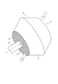
- FIG. 1A is a schematic cross-sectional view in a direction perpendicular to the central axis direction, showing a schematic configuration of an example of a rotary drum type flow device used in the first embodiment of the method for manufacturing a catalyst carrier of the present invention.
- 1B is a cross-sectional view taken along the central axis showing a schematic configuration of a rotating drum in the rotating drum type flow device shown in FIG. 1A. As shown in FIGS.
- the rotary drum type flow device 100 includes a housing 30 and a rotary drum 20 rotatably housed inside the housing 30 around a central axis X in a substantially horizontal direction.
- a rotary drive mechanism (23 g) that rotationally drives the rotary drum 20 around the central axis X, a spray device 40 as a spray unit that sprays the catalyst solution C onto the particulate carrier A housed inside the rotary drum 20, and a housing.
- a dry gas supply device (not shown) for supplying the dry gas G to the body 30 is provided.
- the "substantially horizontal direction” means that the smaller angle formed by the horizontal direction and the central axis X is 0 ° or more and 20 ° or less.
- the rotary drum 20 has the left side in FIG. 1B (the side of the front end opening 23d) as the front side and the right side in FIG. 1B (the side of the rotation drive mechanism 23g) as the rear side.
- the housing 30 has an air supply port 30a for supplying the dry gas G to the inside of the housing 30, and an exhaust gas for exhausting the dry gas G supplied to the inside of the housing 30 from the inside of the housing 30.
- a mouth 30b is formed.
- a gap 30c is provided between the housing 30 and the rotary drum 20, and the partition plate 24, which will be described later, is configured to be movable in the gap 30c.
- the air supply port 30a and the exhaust port 30b are provided at positions facing each other with respect to the central axis X of the rotating drum 20.
- the dry gas G in the rotating drum 20 is configured to flow along the inflow direction H.
- the spraying direction of the catalyst solution C is the disposition direction I of the spray device 40
- the disposition direction I is 0 ° or more and 45 ° or less with respect to the inflow direction H of the dry gas G in the rotating drum 20.
- the rotating drum 20 includes a drum main body 23 and a plurality of partition plates 24.
- the drum main body 23 includes a tubular drum portion 23i and a tapered portion 23c provided on the rear side of the drum portion 23i and formed so as to reduce the diameter toward the rear side. ..
- the drum portion 23i has a tubular peripheral wall portion 23a having a polygonal cross section (in this embodiment, a dodecagonal shape), a ring-shaped front end ring portion 23e provided on the front side of the peripheral wall portion 23a, and a peripheral wall portion 23a. It is provided on the rear side and includes a rear end ring portion 23h having the same shape as the front end ring portion 23e.
- a circular front end opening 23d is formed in the front end ring portion 23e, and the particulate carrier A is supplied into the rotary drum 20 and the particles from the rotary drum 20 are supplied through the front end opening 23d.
- the state carrier A or the produced catalyst carrier can be discharged.
- the tapered portion 23c is formed in a hollow shape inside and communicates with the internal space of the drum portion 23i, and is formed so as to be able to accommodate the particulate carrier A introduced through the front end opening 23d.
- a rotary drive mechanism 23g for rotationally driving the rotary drum 20 is connected to the rear side of the tapered portion 23c via a connecting portion 23f.
- the peripheral wall portion 23a is formed with a ventilation portion that communicates the internal space of the rotating drum 20 with the gap portion 30c outside the rotating drum 20.
- This ventilation portion can be formed, for example, in the form of a mesh in which a plurality of holes having a size that does not allow the particulate carrier to pass through and allows the dry gas to pass through are formed.
- the plurality of partition plates 24 are arranged at predetermined intervals along the outer circumference of the peripheral wall portion 23a between the front end ring portion 23e and the rear end ring portion 23h on the outer circumference of the peripheral wall portion 23a.
- Each partition plate 24 has substantially the same dimensions as the central axis X direction dimension of the peripheral wall portion 23a, and is arranged on the outer periphery of the peripheral wall portion 23a in a direction parallel to the central axis X of the rotating drum 20. Further, the partition plate 24 is erected in the radial direction from each apex portion of the polygonal shape (decagonal shape in FIG. 1A) of the peripheral wall portion 23a toward the outer peripheral side. The partition plate 24 slides along the inner peripheral surface 30d of the housing 30 when the rotating drum 20 rotates.
- a plurality of communication spaces partitioned by a front end ring portion 23e, a front end ring portion 23e, and a plurality of partition plates 24 provided at the apex of the polygonal shape are formed on the outer periphery of the peripheral wall portion 23a, and are outside each communication space.
- the direction (the side facing the peripheral wall portion 23a) is open. Therefore, a plurality of connected spaces are formed on the outer periphery of the peripheral wall portion 23a according to the number of sides of the polygon.
- the cross-sectional shape of the peripheral wall portion 23a is a dodecagonal shape, 12 of the above-mentioned communication spaces are formed.
- the opening portion of each communication space is formed to have the same size as the air supply port 30a formed in the housing 30, and the dry gas G supplied from the air supply port 30a is supplied to each communication space. By suppressing the outflow to the gap portion 30c by the partition plate 24, it can be reliably supplied into the rotating drum 20. Further, since the opening portion of each communication space is formed to have the same size as the exhaust port 30b formed in the housing 30, the dry gas G in the rotating drum 20 is surely passed through each communication space. It can be discharged to the outside of the housing 30 through the exhaust port 30b.
- the ventilation portion at a position facing the air supply port 30a functions as an inflow port 23ab for allowing the drying gas G to flow into the inside of the rotating drum 20, and the exhaust port 30b.
- the ventilation portion at a position facing the above functions as an exhaust port 23ac for discharging the dry gas from the inside of the rotating drum 20.
- the ventilation portion formed in a mesh shape on the peripheral wall portion 23a flows at the timing when it moves to the position corresponding to the air supply port 30a with the rotation of the rotating drum 20 during the drying process.
- the inlet 23ab is formed, and the discharge port 23ac is formed at the timing of moving to the position corresponding to the exhaust port 30b.
- the inflow port 23ab is located above the surface S of the layer (particulate carrier layer) by the particulate carrier A during rotation of the rotary drum 20 in the direction of gravity (vertical direction) with respect to the spray device 40, and the discharge port 23ac is located. , It is located below the surface S of the layer (particulate carrier layer) by the particulate carrier A during rotation of the rotary drum 20 in the direction of gravity (vertical direction) with respect to the spray device 40.
- the length Lb (not shown) of the perpendicular line to the surface S of the layer (particle-like carrier layer) by the particle-like carrier A during rotation can satisfy the relationship of La> Lb, for example, as shown in FIG. 1A. preferable.
- the particulate carrier A is charged into the rotary drum 20 from the front end opening 23d provided at the front end portion 23b of the rotary drum 20.
- the rotating drum 20 into which the particulate carrier A is charged is rotated about the central axis X by the operation of the rotation driving mechanism 23g.
- the particulate carrier A housed in the rotating drum 20 is wound up in the direction of gravity (vertical direction), and then flows downward in the direction of gravity (vertical direction) due to the action of its own weight. Therefore, the particulate carrier A can be efficiently flowed up and down in the direction of gravity (vertical direction), and the particulate carrier A can be efficiently agitated.
- the catalyst solution C is sprayed from the spray device 40 onto the particulate carrier A flowing in the rotary drum 20, and the dry gas G is sprayed into the air supply port 30a, the inflow port 23ab, and the rotary drum 20.
- the dry gas G supplied from the dry gas supply device to the housing 30 and reaching the air supply port 30a moves in a direction substantially opposite to the inflow direction of the dry gas G due to the rotation of the rotating drum 20. Collision with (FIG. 1A).
- the dry gas G passes through the gap 30c of the housing 30 without flowing into the inside of the rotary drum 20, and substantially the entire amount of the dry gas G supplied to the air supply port 30a is the rotary drum 20. Can flow into the interior of the.
- the opening area of the exhaust port 30b is designed to be smaller than the area of the surface S of the layer formed by the particulate carrier A in the rotary drum 20. As a result, it is possible to effectively prevent the dry gas G from passing through the gap 30c without coming into contact with the particulate carrier A.
- substantially the entire amount of the dry gas G supplied to the air supply port 30a is the particulate carrier A, the discharge port 23ac, and the exhaust port housed inside the air supply port 30a, the inflow port 23ab, and the rotary drum 20. It can pass in the order of 30b.
- the rotation speed of the rotary drum 20 in the rotary drum type flow device 100 used in the first embodiment of the method for manufacturing a catalyst carrier of the present invention is 1 rpm or more, although there are differences in the setting due to the difference in the device diameter. It is preferably 3 rpm or more, more preferably 5 rpm or more, preferably 100 rpm or less, more preferably 50 rpm or less, and particularly preferably 30 rpm or less.
- the rotation speed of the rotating drum 20 is 1 rpm or more, a sufficient stirring effect can be obtained, and when the rotation speed is 100 rpm or less, the particulate carrier A adheres to the inner wall surface of the peripheral wall portion 23a of the rotating drum 20 by centrifugal force. It can be suppressed to continue.
- the inflow direction H of the dry gas G in the rotary drum 20 In any of the arrangement directions I of the spraying device 40 as the spraying direction of the catalyst solution C, with respect to the surface S of the layer (particle-like carrier layer) by the particulate carrier A housed in the rotating drum 20 during rotation. It is preferable that it is substantially vertical. As described above, both the inflow direction H and the arrangement direction I should be substantially perpendicular to the surface S of the layer (particle-like carrier layer) formed by the particle-like carrier A housed in the rotating drum 20 during rotation.
- the catalyst solution C can be efficiently sprayed on the particulate carrier A, and the particulate carrier A sprayed with the catalyst solution C can be efficiently dried.
- the spray device 40 as a spray unit when the spray device 40 as a spray unit includes a constant flow rate pump, a catalyst solution is provided. C can be sent quantitatively, and thus the flow rate can be easily controlled. Further, if the spray device 40 as a spray unit is equipped with an automatic spray gun, fine and uniform mist can be spray-applied, and as a result, a fine coating with a small agglomerate generation rate and a uniform particle size can be obtained. Can be carried out.
- the spray device 40 as the spray unit is not particularly limited, and may be, for example, a two-fluid nozzle or may have a mist generator such as an ultrasonic atomizer.
- the spray device 40 as a spray unit is preferably provided in a direction (90 degrees ⁇ 30 degrees) substantially perpendicular to the surface S of the layer (particle-like carrier layer) formed by the particle-like carrier A during rotation, and is preferably rotated. It is preferable that the distance from the surface S of the layer (particulate carrier layer) by the particulate carrier A at the time is 30 mm or more and 1000 mm or less.
- the catalyst carrier produced by the method for producing a catalyst carrier of the present invention has a particulate carrier and a catalyst layer formed on the outermost surface of the particulate carrier. That is, the catalyst carrier is manufactured by the method for producing a catalyst carrier of the present invention, and may have a catalyst formed on the outermost surface. For example, it has only one catalyst layer. It may have a plurality of catalyst layers.
- the catalyst carrier functions to mediate, promote, and improve the efficiency of the synthesis and growth of fibrous carbon nanostructures in the reaction field.
- the catalyst carrier plays a role of taking in a carbon raw material from the supplied raw material gas and synthesizing fibrous carbon nanostructures such as carbon nanotubes on the surface without particular limitation. More specifically, for example, when the catalyst has a fine particulate shape, each catalyst particle continues to generate carbon while forming a tube-like structure having a diameter corresponding to the size of the catalyst particle. This allows the fibrous carbon nanostructures to be synthesized and grown.
- the catalyst carrier is usually used after the catalyst is reduced by contacting it with a high-temperature reducing gas (for example, hydrogen gas, ammonia, water vapor, and a mixed gas thereof).
- the particulate carrier has a particle shape made of an arbitrary material, and is a portion forming a matrix structure for supporting, fixing, film-forming, or forming a catalyst on the surface of the carrier.
- the catalyst carrier produced by using the particulate carrier is also usually in the form of particles.
- the term "particle-like" may mean that the particles have a substantially particle shape, and the aspect ratio is preferably 10 or less. When the aspect ratio of the particulate carrier is 10 or less, the catalyst solution described later can be uniformly sprayed.
- the "aspect ratio of the particulate carrier" can be determined by measuring the minor axis and the major axis of 100 randomly selected particulate carriers using a transmission electron microscope.
- the structure of the particulate carrier may be only the particulate carrier, or may be a particulate carrier with an underlayer provided with an arbitrary underlayer for satisfactorily supporting the catalyst on the surface of the particulate carrier.
- the base layer is made of any material, and for example, one layer or two or more layers can be formed on the surface of the particulate carrier. From the viewpoint of satisfactorily supporting the catalyst on the particulate carrier and effectively utilizing the catalyst carrier, the particulate carrier is preferably a particulate carrier with an underlayer.
- the composition of the base layer is not particularly limited and can be appropriately selected depending on the type of the particulate carrier and the type of the catalyst described later.
- the base layer can be formed of, for example, a ceramic material such as alumina, titania, titanium nitride, or silicon oxide. Further, the film thickness of the underlying layer to be formed can also be appropriately adjusted depending on the desired amount of catalyst supported.
- the base layer can be formed on the surface of the particulate carrier by, for example, using a solution for forming the ceramic material instead of the catalyst solution and carrying out the spraying step, the drying step and the firing step described later. .. Further, the particulate carrier may have a catalyst layer on its surface.
- the catalyst layer may be a used one, in which case the used particulate carrier can be reused in the present invention.
- the particle density (apparent density) of the particulate carrier is preferably 2.0 g / cm 3 or more, more preferably 3.5 g / cm 3 or more, and 9.0 g / cm 3 or less. Is preferable, and 6.0 g / cm 3 or less is more preferable.
- the particle density (apparent density) of the particulate carrier is within the above range, aggregation between the particulate carriers due to the catalyst solution can be suppressed, the fluidity of the particulate carrier can be improved, and the particulate carrier can be prepared.
- the catalyst layer can be formed more uniformly on the surface.
- the material of the particulate carrier is not particularly limited, but preferably contains a metal oxide, and magnesium (Mg), aluminum (Al), silicon (Si), zirconium (Zr), and molybdenum (Zr). It is more preferable to contain a metal oxide containing at least one element selected from the group consisting of Mo), and it is further preferably composed of a metal oxide such as zirconium dioxide (zirconia), aluminum oxide, and zirconium. preferable. Since the particulate carrier is composed of a metal oxide, heat resistance can be improved. Further, by using zirconium dioxide (zirconia), aluminum oxide, or zircon as a metal oxide, heat resistance can be further improved.
- the particle size (diameter) of the particulate carrier is not particularly limited, but is preferably 50 ⁇ m or more and 10 mm or less. When the diameter of the particulate carrier is 50 ⁇ m or more, the particulate carrier and the CNT can be easily separated after CNT synthesis, and when it is 10 mm or less, the total surface area of the particles in the same volume is high. Therefore, the production efficiency of CNTs can be increased.
- the "particle size (diameter)" of the particulate carrier means the volume average particle size D50.
- the volume average particle size D50 represents the particle size at which the cumulative volume calculated from the small diameter side in the particle size distribution (volume basis) measured by the laser diffraction method for the particulate carrier is 50%.
- the method for producing a catalyst carrier of the present invention for example, unlike the conventional fluidized bed method, it is not necessary to suspend the particulate carrier, so that a particulate carrier having a large particle size can be used. As a result, the mesh opening in the ventilation portion provided for preventing the catalyst carrier from falling off from the rotating drum can be increased, and the pressure loss in the ventilation portion can be reduced.
- the porosity of the particulate carrier is preferably 10% or less. When the porosity of the particulate carrier is 10% or less, a more uniform catalyst layer can be formed.
- the catalyst is supported on the surface of the particulate carrier described above. Further, the catalyst may be directly supported on the surface of the particulate carrier as a catalyst layer to form a catalyst carrier, or may be indirectly supported on the surface of the particulate carrier via the underlayer or the like.
- the catalyst carrier may be configured (for example, from the inside, a particulate carrier / base layer / catalyst layer). Further, for example, a plurality of layers may be optionally provided as the base layer and / or the catalyst layer.
- the catalyst is usually present on the outermost surface of the catalyst carrier and serves to promote the synthesis of fibrous carbon nanostructures.
- a substantially cylindrical rotating drum 20 in which a particulate carrier A is housed is rotated around the central axis X, thereby causing the particulate carrier A.
- spraying the catalyst solution C on the particulate carrier A in the rotary drum spraying step
- drying step drying from the outside of the rotary drum 20 to the inside of the rotary drum 20.
- drying step of inflowing the gas G and bringing the dry gas G into contact with the particulate carrier A sprayed with the catalyst solution C in the spraying step to dry the catalyst solution C is included.
- a step of firing the particulate carrier A at 50 ° C. or higher and 900 ° C. or lower may be further included.
- at least a part of the implementation period of the stirring step and at least a part of the implementation period of the spraying step overlap.
- the temperature at the time of stirring is not particularly limited and can be appropriately selected depending on the type of the particulate carrier A, the composition of the catalyst solution C described later, and the like.
- the catalytic solution is sprayed onto the particulate carrier in the rotating drum.
- at least a part of the stirring step implementation period and at least a part of the spraying step implementation period overlap, so that the spraying step is performed on the stirred particulate carrier A.
- the period during which the catalyst solution C is sprayed is included. As a result, a coating film of the catalyst solution C can be uniformly formed on the surface of the particulate carrier A.
- the method of spraying the catalyst solution C onto the particulate carrier A is not particularly limited, and for example, a method of spraying from a spray device 40 (spraying means) such as a spray gun or a spray nozzle is preferable.
- the conditions for spraying the catalyst solution C onto the particulate carrier A are not particularly limited, and known conditions can be adopted, such as the amount of spraying, the size of mist particles to be sprayed, and the spraying time. It can be selected as appropriate.
- the spray air pressure is preferably, for example, about 0.1 MPa or more and 0.5 MPa or less.
- a mixed solution of two or more kinds of catalyst solutions C may be sprayed from one spray device 40 (spraying means) or separate spray devices 40 (spraying). Means) may be used for spraying, but it is preferable to spray using separate spraying devices 40 (spraying means).
- the catalyst component contained in the catalyst solution C preferably contains at least one metal of nickel (Ni), iron (Fe), cobalt (Co), and molybdenum (Mo).
- the catalyst solution contains at least one metal of nickel (Ni), iron (Fe), cobalt (Co), and molybdenum (Mo)
- it can function as a catalyst for CNT synthesis.
- Specific examples of the catalyst component contained in the catalyst solution include iron acetate, ferrocene, iron acetylacetonate, cobalt acetate, and the like.
- the solvent contained in the catalyst solution C various organic solvents such as alcohol, glycol, ketone, ether, esters and hydrocarbons can be used, but it is preferable to use alcohols.
- the catalyst solution C may contain water.
- the catalyst solution C may contain both a solvent and water, or may contain only one of them.
- the catalyst component is dissolved in water and / or a solvent.
- the solid content concentration of the catalyst solution C is not particularly limited, but is preferably 20% by mass or less, and more preferably 10% by mass or less. When the solid content concentration of the catalyst solution C is 20% by mass or less, the coating film is stable and a catalyst carrier in which the catalyst layer is uniformly formed on the surface of the particulate carrier can be obtained. Fibrous carbon nanostructures can be synthesized with high efficiency and are excellent in mass productivity. Further, the catalyst solution C may contain the components of the base layer.
- a uniform catalyst coating film can be formed on the surface of the particulate carrier A by drying the particulate carrier A sprayed with the catalyst solution C.
- the dry gas G is allowed to flow into the rotary drum 20 from the outside of the rotary drum 20, and the dry gas G is applied to the particulate carrier A on which the catalyst solution C is sprayed in the above spraying step. By contacting them, the catalyst solution C adhering to the surface of the particulate carrier A is dried to form a catalyst coating film.
- the particulate carrier A on which the catalyst coating film is formed can be used as it is as a catalyst carrier, but if necessary depending on the composition of the catalyst solution C, after the drying step, the particulate carrier A on which the catalyst coating film is formed is continuously used. On the other hand, the firing step described later may be performed.
- the catalyst coating film forms a catalyst layer.
- the drying gas G used in the drying step is not particularly limited, and examples thereof include compressed air and nitrogen.
- the term "dry gas” means a gas used for drying a particulate carrier sprayed with a catalyst solution. Therefore, the "dry gas” itself may have any attribute.
- the dew point of the "dry gas” is not particularly limited.
- the temperature of the dry gas G is not particularly limited, and is preferably 0 ° C. or higher, more preferably 20 ° C. or higher, further preferably 25 ° C. or higher, and 200 ° C. or lower. Is preferable, and the temperature is more preferably 100 ° C. or lower. In the drying step, when the dry gas G is introduced in a state where the temperature is adjusted to 0 ° C.
- the particulate carrier A is in a heated and fluidized state, so that the surface of the catalyst solution C to be sprayed is formed. Even when the tension is high, the catalyst solution C is quickly dried to suppress repelling, and the catalyst coating film is formed more uniformly on the surface of the particulate carrier A.
- the amount of dry gas supplied is not particularly limited, and is preferably 50 L / min or more, more preferably 100 L / min or more, and preferably 10000 L / min or less.
- the dry gas supply amount is 50 L / min or more, a sufficient drying effect can be obtained, and when the dry gas supply amount is 10000 L / min or less, the scattering of the particulate carrier A due to the dry gas G can be suppressed and the scattering of the particulate carrier A can be suppressed. It is possible to prevent the spray droplets from drying before adhering to the particulate carrier A.
- the atmospheric concentration (solvent concentration) in the rotating drum 20 in the drying step is not particularly limited, and is preferably 2% by volume or less, and more preferably 1% by volume or less. When the atmospheric concentration (solvent concentration) in the rotating drum 20 is not more than the above upper limit value, drying can be stabilized.
- the particulate carrier A that has undergone the drying step may be fired at 50 ° C. or higher and 900 ° C. or lower.
- the firing may be carried out using a muffle furnace, a fluidized bed or a rotary kiln after taking out the particulate carrier A having the catalyst coating film formed on the surface from the rotary drum 20, or without taking it out from the rotary drum 20. , You may do it in the rotary drum 20 as it is.
- the firing is preferably performed in an oxygen atmosphere.
- the firing temperature is preferably about 300 ° C. or higher.
- the firing time is preferably 5 minutes or more and 60 minutes or less, and more preferably 5 minutes or more and 40 minutes or less.
- a coating film containing aluminum needs to be fired at 300 ° C. or higher.
- a coating film containing an iron catalyst needs to be fired at 80 ° C. or higher.
- the thickness of the catalyst layer is usually in the range of 0.1 nm or more and 100 nm.
- the film thickness of the catalyst layer containing the components of the base layer is preferably 10 nm or more and 100 nm or less, and the film thickness of the catalyst layer not containing the components of the base layer is preferably 0.1 nm or more and 10 nm or less.
- the stirring step at least a part of the spraying step, and at least a part of the drying step. And are preferably duplicated.
- the start timing of each step is not particularly limited, and after starting the stirring step, the spraying step and the drying step may be started simultaneously or sequentially, or these three steps may be started at the same time.
- the spraying step may be started in advance, and then the stirring step and the drying step may be started simultaneously or sequentially.
- the end timing of each step is not particularly limited, and for example, the spraying step may be finished prior to the other steps, and then the stirring step and the drying step may be finished simultaneously or sequentially, or all steps. May end at the same time.
- the droplets of the catalyst solution C sprayed from the spray device 40 are dried (the solvent in the droplets volatilizes). Since it adheres to the particulate carrier A to be sprayed before, and then the adhered catalyst solution C dries (the solvent in the adhered catalyst solution C volatilizes) to form a coating film, the particulate carrier is formed.
- the catalyst layer can be uniformly formed on the surface of A.
- the drying speed of the catalyst solution C is, for example, (i) volatility of the solvent in the catalyst solution C, (ii) the size of droplets, (iii) the injection speed of the catalyst solution C, and (iv) drying. It can be adjusted by adjusting the supply amount of the gas G, (v) the temperature of the dry gas G, and the like.
- FIG. 2 shows a configuration (3) of a particulate carrier / base layer (aluminum oxide layer) / iron catalyst layer using the rotary drum type flow device used in the first embodiment of the method for producing a catalyst carrier of the present invention. It is a figure for demonstrating the case of producing the catalyst carrier which has a layer structure).
- the particulate carrier 1 is prepared (FIG. 2 (a)).
- the prepared particulate carrier 1 (particulate carrier A) is put into the rotating drum 20 via the front end opening 23d and stirred (stirring step) to form the base layer, so that the spray device 40
- the aluminum-containing solution is sprayed using the above (spraying step) and dried using the drying gas G flowing into the rotating drum 20 through the air supply port 30a and the inflow port 23ab (drying step).
- the coating film 2 containing the above is formed to prepare a particulate carrier 3 with a coating film having the coating film 2 formed on the surface (FIG. 2 (b)).
- the particulate carrier 3 with a coating film on which the coating film 2 is formed is fired (firing step), and the base layer 4 made of aluminum oxide (Al 2 O 3) is formed on the surface of the particulate carrier 1.
- the formed particulate carrier 5 with an underlayer is prepared (FIG. 2 (c)).
- the particulate carrier 5 with a base layer is put into the rotary drum 20 through the front end opening 23d and stirred (stirring step), and the iron-containing solution as the catalyst solution C is sprayed using the spray device 40. (Spraying step), and drying using the dry gas G that has flowed into the rotating drum 20 through the air supply port 30a and the inflow port 23ab (drying step), a coating film containing an iron catalyst on the surface.
- a catalyst carrier composed of the particulate carrier 7 on which 6 is formed is obtained (FIG. 2 (d)).
- FIG. 3 shows a configuration (3) of a particulate carrier / base layer (aluminum oxide layer) / iron oxide layer using the rotary drum type flow device used in the first embodiment of the method for producing a catalyst carrier of the present invention. It is a figure for demonstrating the case of producing the catalyst carrier which has a layer structure).
- the particulate carrier 1 is prepared (FIG. 3 (a)).
- the prepared particulate carrier 1 (particulate carrier A) is put into the rotating drum 20 via the front end opening 23d and stirred (stirring step) to form the base layer, so that the spray device 40
- the aluminum-containing solution is sprayed using the above (spraying step) and dried using the drying gas G flowing into the rotating drum 20 through the air supply port 30a and the inflow port 23ab (drying step).
- the coating film 2 containing the above is formed to prepare a particulate carrier 3 with a coating film having the coating film 2 formed on the surface (FIG. 3 (b)).
- the particulate carrier 3 with a coating film having the coating film 2 formed on the surface is fired (firing step), and the underlayer 4 formed of the aluminum oxide layer is formed on the surface of the particulate carrier 1.
- a particulate carrier 5 is prepared (FIG. 3 (c)).
- the particulate carrier 5 with a base layer is put into the rotating drum 20 through the front end opening 23d and stirred (stirring step), while the iron-containing solution as the catalyst solution C is sprayed using the spray device 40.
- spraying spraying step
- drying with the dry gas G flowing into the inside of the rotating drum 20 through the air supply port 30a and the inflow port 23ab drying step
- the surface is coated with an iron catalyst.
- a particulate carrier 7 with a catalyst coating film on which the film 6 is formed is obtained (FIG. 3 (d)).
- the particulate carrier 7 with a catalyst coating is fired (firing step) to obtain a catalyst carrier 11 on which an iron oxide layer 10 (catalyst layer) is formed on the surface of the particulate carrier 5 with a base layer (FIG. 3 (e)).
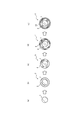
- FIG. 4 shows a configuration (two-layer configuration) of a particulate carrier / a catalyst layer composed of aluminum oxide and iron oxide, using a rotary drum type flow device used in the first embodiment of the method for producing a catalyst carrier of the present invention. It is a figure for demonstrating the case of manufacturing the catalyst carrier which has ().
- the particulate carrier 1 is prepared (FIG. 4 (a)).
- the prepared particulate carrier 1 is put into the rotating drum 20 through the front end opening 23d and stirred (stirring step), and aluminum and iron are sprayed using the spray device 40.
- the catalyst solution C contained is sprayed (spraying step) and dried using the drying gas G flowing into the rotating drum 20 through the air supply port 30a and the inflow port 23ab (drying step), and the aluminum and aluminum are dried.
- a coating film 12 containing an iron catalyst is formed to prepare a particulate carrier 13 with a coating film (FIG. 4 (b)).
- the coated particulate carrier 13 is fired (firing step) to obtain a catalyst carrier 15 on which a catalyst layer 14 containing aluminum oxide and iron oxide is formed on the surface of the particulate carrier 1 (FIG. 4). (C)).
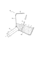
- FIG. 5 shows a configuration of a particulate carrier / a catalyst layer composed of aluminum oxide and iron oxide / an iron oxide layer using a rotary drum type flow device used in the first embodiment of the method for producing a catalyst carrier of the present invention. It is a figure for demonstrating the case of producing the catalyst carrier which has (three-layer structure).
- the particulate carrier 1 is prepared (FIG. 5 (a)).
- the prepared particulate carrier 1 (particulate carrier A) is put into the rotary drum 20 via the front end opening 23d and stirred (stirring step), while the catalyst solution C containing aluminum and iron is mixed.
- the particulate carrier 15 on which the catalyst layer 14 is formed is put into the rotary drum 20 via the front end opening 23d and stirred (stirring step), while spraying the iron-containing solution as the catalyst solution C.
- the iron catalyst is contained by spraying using 40 (spraying step) and drying using the drying gas G flowing into the rotating drum 20 through the air supply port 30a and the inflow port 23ab (drying step).
- the coating film 16 to be coated is formed to prepare a particulate carrier 17 with a catalyst coating film (FIG. 5 (d)).
- the particulate carrier 17 with the catalyst coating was fired (firing step), and the catalyst carrier 19 on which the iron oxide layer 18 was formed as the catalyst layer on the surface of the particulate carrier 1 on which the catalyst layer 14 was formed was formed. It is prepared (FIG. 5 (e)).
- the central axis X is configured to be in a substantially horizontal direction, but the configuration is not limited to this, and the central axis X is as described in the second embodiment described later.
- the central axis Y corresponding to may be inclined from the horizontal direction, and the inclination angle thereof is not particularly limited.
- the dry gas G is supplied into the rotary drum 20 from the peripheral wall portion 23a corresponding to the outer periphery of the rotary drum 20 and discharged, but the supply position and the discharge position of the dry gas G are not particularly limited.
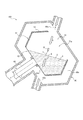
- FIG. 6A is a schematic cross-sectional view taken along the central axis Y, showing a schematic configuration of an example of a rotary drum type flow device used in the second embodiment of the method for manufacturing a catalyst carrier of the present invention.
- FIG. 6B. 6A is a perspective view showing a schematic configuration of a rotary drum in the rotary drum type fluidizer shown in FIG. 6A, and FIG.
- FIG. 6C shows a schematic configuration of a modified example of the rotary drum in the rotary drum type fluidizer shown in FIG. 6A.
- the second embodiment is different from the first embodiment mainly in the angle of the rotation axis of the rotating drum.
- the rotary drum type flow device 200 rotationally drives the housing 80, the rotary drum 50 rotatably housed around the central axis Y in a predetermined direction, and the rotary drum 50 around the central axis Y.
- the "predetermined direction” means a direction forming an angle of more than 20 ° and less than 90 ° with respect to the horizontal direction, and forming an angle of more than 20 ° and 70 ° or less with respect to the horizontal direction.
- the direction is preferable, and the direction forming an angle of 30 ° or more and 45 ° or less with respect to the horizontal direction is more preferable.
- the rotating drum 50 rotates around a central axis Y (a line passing through the center of the front end portion 51 (not shown) and the center P of the rear end portion 52) forming a predetermined angle with respect to the horizontal direction.
- a central axis Y a line passing through the center of the front end portion 51 (not shown) and the center P of the rear end portion 52
- the particulate carrier A housed inside the rotating drum 50 can be efficiently agitated.
- the spray area of the catalyst solution C and the contact area of the dry gas G can be increased.
- the rotary drum 50 can increase the filling rate of the particulate carrier A.
- the rotating drum 50 is provided on a peripheral wall portion 53 having a predetermined shape (see FIGS.
- a front end portion 51 provided on the front side of the peripheral wall portion 53 in the Y direction of the central axis, and a rear side of the peripheral wall portion 53 in the Y direction of the central axis. It has a rear end portion 52 that has been removed.
- the front side in the central axis Y direction is a side located upstream of the intersection obtained when the spray directions are crossed with respect to the central axis Y.
- the rear side in the Y direction of the central axis is the opposite side to the front side. More specifically, in the illustrated embodiment, the front end opening 51a provided for supplying the particulate carrier A to the rotary drum 50 and discharging the particulate carrier A or the catalyst carrier from the rotary drum 50.
- the side is the front side, the opposite side of the front side, and the shaft side on which the rotation drive mechanism 60 is provided is the rear side.
- the housing 80 has an air supply port 80a for supplying the dry gas G to the inside of the housing 80 and an exhaust gas G supplied to the inside of the housing 80 for exhausting from the inside of the housing 80.
- a mouth 80b is provided.
- the housing 80 is provided on the outer peripheral side of the rotating drum 50, and is provided with a gap 80c for communicating the air supply port 80a and the exhaust port 80b.
- the front end portion 51 continuous with the front end of the peripheral wall portion 53 and the rear end portion 52 continuous with the rear end of the peripheral wall portion 53 are provided with ventilation portions for communicating the inside and the outside of the rotating drum 50, respectively.
- the front end opening 51a functions as a ventilation portion (inflow port for allowing the dry gas G to flow into the inside of the rotary drum 50), and at the rear end portion 52, it is formed in a mesh shape in which a plurality of holes are formed.
- the mesh opening 52a is provided as a ventilation portion (a discharge port for discharging the dry gas G from the inside of the rotary drum 50).
- the particulate carrier A is put into the rotary drum 50 from the front end opening 51a provided in the front end portion 51 of the rotary drum 50.
- the rotating drum 50 into which the particulate carrier A is charged is rotated by the operation of the rotation driving mechanism 60 about the central axis Y in a predetermined direction.
- the particulate carrier A housed in the rotating drum 50 is wound up in the direction of gravity (vertical direction), and then flows downward in the direction of gravity (vertical direction) due to the action of its own weight.
- the particulate carrier A can be efficiently flowed up and down in the direction of gravity (vertical direction), and the particulate carrier A can be efficiently agitated. Further, by using the rotary drum 50, the spray area of the catalyst solution C by the spray device 70 and the contact area of the dry gas G (the area of the surface S of the layer by the particulate carrier A in FIG. 6A) can be increased. In addition, the filling rate of the particulate carrier A can be increased.
- the catalyst solution C is sprayed onto the particulate carrier A from the spray device 70 as a spray unit while rotating the rotary drum 50 as described above.
- the catalyst solution C can be uniformly adhered to the surface of the particulate carrier A.
- the dry gas G is passed through the air supply port 80a, the front end opening 51a, the particulate carrier A housed inside the rotary drum 50, the mesh opening 52a, and the exhaust port 80b in this order.
- the surface of the particulate carrier A to which the catalyst solution C is attached is dried, and the particulate carrier A on which the catalyst coating film is formed is obtained.
- a baffle may be provided on the inner wall surface of the peripheral wall portions 23a and 53 of the rotary drums 20 and 50 in the rotary drum type flow devices 100 and 200 used in the method for manufacturing the catalyst carrier of the present invention. ..
- the baffle is installed on the inner wall surface of the peripheral wall portions 23a and 53 of the rotating drums 20 and 50, it is preferable to install the baffle so as to spiral in the direction of the central axis of the rotating drums 20 and 50. Further, it is preferable that the spraying unit is not in the vicinity of the spraying devices 40 and 70.
- the particulate carrier A is moved to the rear side (shaft side) of the rotating drums 20 and 50 to form particles. It is possible to prevent the carrier A from leaking from the front end openings 23d and 51a provided in the front end portions 23b and 51, and it is possible to obtain a sufficient stirring effect.
- the shapes of the rotary drums 20 and 50 in the rotary drum type flow devices 100 and 200 used in the method for producing the catalyst carrier of the present invention are not particularly limited, and may be, for example, a polygonal (polygonal column) shape. It may be cylindrical (cylindrical), but it is preferably polygonal (polygonal prism). Since the rotary drums 20 and 50 have a polygonal (polygonal prism) shape, the particulate carrier can be efficiently agitated, and the agitation property is particularly high for particles having a low angle of repose.
- the polygonal (polygonal prism) shape and the cylindrical (cylindrical) shape include those having protrusions on the side surfaces (see, for example, FIGS. 6A to 6C) and those having recesses (constrictions). Here, it is preferable to have a protruding portion in terms of the capacity of the rotating drum.
- the size of the mesh opening (maximum length of one hole) formed in the peripheral wall portion 23a and the mesh opening 52a of the rotating drums 20 and 50 used in the method for producing the catalyst carrier of the present invention is particularly high. Although there is no limitation, it is preferably 80% or less, more preferably 70% or less, and more preferably 20% or more of the average particle size (average diameter) of the particulate carrier A. When the size of the mesh opening is 80% or less of the average particle size (average diameter) of the particulate carrier A, it is possible to prevent the particulate carrier A from falling off from the rotating drums 20 and 50.
- the size of the mesh opening is 20% or more of the average particle size (average diameter) of the particulate carrier A
- the pressure loss of the peripheral wall portion 23a and the mesh opening 52a can be reduced, and the catalyst
- the particulate carrier A sprayed with the solution C can be dried more efficiently.
- a ventilation portion for communicating the inside and the outside of the rotary drum 20 is provided on substantially the entire peripheral wall portion 23a.
- a plurality of ventilation portions may be provided in a part of the peripheral wall portion 23a, and in that case, the ventilation portions are preferably located so as to face each other via the central axis X.
- the number of ventilation portions is preferably an even number.
- the ventilation part inflow port 23ab
- the particulate carrier A housed inside the rotary drum 20 passes through the ventilation part (inflow port 23ab), the particulate carrier A housed inside the rotary drum 20, the ventilation part (exhaust port 23ac), and the exhaust port 30b in this order.
- the plurality of partition plates 24 are provided on the rotating drum 20. It is arranged on the outer periphery of the peripheral wall portion 23a at predetermined intervals in the circumferential direction, and the opening area of the exhaust port 30b is designed to be smaller than the area of the surface S of the layer formed by the particulate carrier A in the rotating drum 20. preferable.
- the dry gas G is suppressed from passing through the gap portion 30c without coming into contact with the particulate carrier A, and substantially the entire amount of the dry gas G supplied to the air supply port 30a is distributed to the air supply port 30a.
- the ventilation portion (inflow port 23ab), the particulate carrier A housed inside the rotating drum 20, the ventilation portion (exhaust port 23ac), and the exhaust port 30b can be passed in this order.
- the front end opening 51a is an open system in which nothing is provided.
- the entire surface or a part of the front end opening 51a may be formed in a mesh shape.
- the particulate carrier A is supplied into the rotary drum 50 and the particulate carrier from the rotary drum 50 is supplied through the front end opening 51a.
- the mesh is installed in a detachable state so that the catalyst carrier A or the manufactured catalyst carrier can be discharged.
- a mesh opening 52a is provided on the entire surface of the rear end portion 52.
- the mesh opening 52a may be provided in a part of the rear end portion 52 without limitation.
- the front end opening 51a and the mesh opening 52a are respectively the front end 51 of the rotary drum 50.
- the present invention is not limited to this, and it may be provided on a part of the front end portion 51 and / or the rear end portion 52.
- the front end opening 51a and the mesh opening 52a are provided at a plurality of positions in a part of the front end portion 51 and the rear end portion 52, respectively, the front end opening 51a and the mesh opening 52a are the central axes.
- the front end openings 51a are located so as to face each other via Y, and the front end opening 51a is preferably located above the gravitational direction (vertical direction) of the particulate carrier A, while the mesh opening 52a is located. It is preferably located below the gravitational direction (vertical direction) of the particulate carrier A.
- a mesh opening 52a is formed along a substantially vertical direction of the central axis Y of the rotary drum 50.
- the present invention is not limited to this, and for example, as shown in FIG. 6C, the mesh opening 52a is formed along a direction forming a predetermined angle with the vertical direction of the central axis Y of the rotating drum 50. You may.
- a plurality of partition plates are predetermined in the circumferential direction on the outer periphery of the peripheral wall portion 53. It may be arranged at intervals. If a plurality of partition plates (not shown) are arranged on the outer periphery of the peripheral wall portion 53 at predetermined intervals in the circumferential direction, the dry gas G is suppressed from passing through the gap portion 80c, and the air supply port 80a is suppressed.
- the air supply port 80a, the front end opening 51a, the particulate carrier A housed inside the rotary drum 50, the mesh opening 52a, and the exhaust port 80b can be passed in this order. it can.
- the method for producing a fibrous carbon nanostructure of the present invention is a method for producing a fibrous carbon nanostructure. Then, in the method for producing a fibrous carbon nanostructure of the present invention, a raw material gas is supplied to the catalyst carrier obtained by the method for producing a catalyst carrier of the present invention, and the fibrous carbon nanostructure is placed on the catalyst layer. The step of synthesizing the structure (synthesis step) is included.
- the fibrous carbon nanostructure is not particularly limited, and examples thereof include a fibrous carbon nanostructure having an aspect ratio of more than 10.
- examples of the fibrous carbon nanostructures include CNTs and vapor-grown carbon fibers.
- the "aspect ratio of fibrous carbon nanostructures" measures the diameter (outer diameter) and length of 100 fibrous carbon nanostructures randomly selected using a transmission electron microscope. Can be obtained.
- the fibrous carbon nanostructure obtained by the production method of the present invention contains CNT will be described, but the present invention is not limited thereto.
- CNT is a material having a structure in which a graphene sheet is wound in a tubular shape and has a one-dimensional structure having a very large aspect ratio (see Non-Patent Document 1).
- the fibrous carbon nanostructures containing CNTs may be composed of only CNTs, or may be a mixture of CNTs and fibrous carbon nanostructures other than CNTs.
- the CNT may be a single-walled carbon nanotube and / or a multi-walled carbon nanotube without particular limitation, but from the viewpoint of enhancing various characteristics such as mechanical strength, electrical properties, and thermal conductivity.
- the CNT is preferably composed of 10 or less layers, more preferably composed of 5 or less layers, and further preferably a single-walled carbon nanotube.
- the single-walled carbon nanotube / multi-walled carbon nanotube can be appropriately adjusted by changing various reaction conditions such as the size of the catalyst, the composition of the catalyst, the reaction time, and the flow rate of the raw material gas.
- the average diameter of the fibrous carbon nanostructures containing CNTs can be set to a desired value depending on various uses. For example, if the particle size of the metal fine particles as a catalyst generated by the reduction of the catalyst layer described above is usually about 1 nm or more and 2 nm or less, the average diameter of CNT or the like is about 1 nm, and the particle size of the metal fine particles is about 30 nm. For example, the average diameter of CNT or the like can be adjusted to about 20 nm or more and 30 nm or less. In general, the finer the average diameter of CNTs, the better the various properties.
- the "average diameter" of the fibrous carbon nanostructures containing CNTs is determined by measuring the diameter (outer diameter) of 100 fibrous carbon nanostructures randomly selected using, for example, a transmission electron microscope. Can be sought.
- the average length of the fibrous carbon nanostructures containing CNTs can be set to a desired value depending on various uses, but the average length at the time of synthesis is preferably 1 ⁇ m or more, preferably 50 ⁇ m or more. Is more preferable. If the average length of the fibrous carbon nanostructures containing CNTs at the time of synthesis is 1 ⁇ m or more, the obtained fibrous carbon nanostructures can be provided with various mechanical strength, electrical properties, thermal conductivity and other properties. This is because it can be exhibited better. In addition, the longer the length of the fibrous carbon nanostructure containing CNT during synthesis, the more easily damage such as breakage or cutting occurs in the fibrous carbon nanostructure. Therefore, the fibrous carbon nanostructure containing CNT during synthesis is likely to occur.
- the average length of the structure is preferably 5000 ⁇ m or less.
- the "average length" of the fibrous carbon nanostructures containing CNTs can be appropriately adjusted by, for example, changing the synthesis reaction time.
- a raw material gas is supplied to the catalyst carrier obtained by the method for producing a catalyst carrier of the present invention, and the fibrous carbon nanostructure is placed on the catalyst layer. Synthesize the body.
- a raw material gas was supplied to the catalyst layer of the outermost layer of the catalyst carrier obtained by the method for producing a catalyst carrier of the present invention to generate fibrous carbon nanostructures on the catalyst layer.
- the catalyst carrier is usually subjected to a reduction treatment before being used in a method for producing a fibrous carbon nanostructure. Then, in the synthesis step, at least one of the catalyst layer and the raw material gas is usually heated, but from the viewpoint of growing the fibrous carbon nanostructures at a uniform density, it is preferable to heat at least the raw material gas.
- the heating temperature is preferably 400 ° C. or higher and 1100 ° C. or lower.
- the synthesis step is carried out by introducing a raw material gas, optionally an inert gas, a reducing gas, and / or a catalyst activator into the fibrous carbon nanostructure growth furnace containing the catalyst carrier.
- a gaseous substance containing a carbon source is used at the temperature at which the fibrous carbon nanostructures grow.
- hydrocarbons such as methane, ethane, ethylene, propane, butane, pentane, hexane, heptane, propylene and acetylene are preferred.
- lower alcohols such as methanol and ethanol, and low carbon number oxygen compounds such as acetone and carbon monoxide may be used. Mixtures of these can also be used.
- the source gas may be diluted with an inert gas.
- the inert gas may be any gas that is inert at the temperature at which the fibrous carbon nanostructures grow and does not react with the growing fibrous carbon nanostructures, and is preferably a gas that does not reduce the activity of the catalyst. ..
- rare gases such as helium, argon, neon and krypton; nitrogen; hydrogen; and mixed gases thereof can be exemplified.
- the reducing gas for example, hydrogen gas, ammonia, water vapor, or a mixed gas thereof can be used. Further, the reducing gas may be a mixed gas obtained by mixing hydrogen gas with an inert gas such as helium gas, argon gas or nitrogen gas.
- the catalyst activating substance used here is generally a substance containing oxygen, and is preferably a substance that does not significantly damage the fibrous carbon nanostructures at the temperature at which the fibrous carbon nanostructures grow.
- low carbon oxygen-containing compounds such as water, oxygen, ozone, acidic gas, nitrogen oxide, carbon monoxide and carbon dioxide; alcohols such as ethanol and methanol; ethers such as tetrahydrofuran; ketones such as acetone; Aldehydes; esters; as well as mixtures thereof are effective.
- water, oxygen, carbon dioxide, carbon monoxide, and ethers are preferable, and water is particularly preferable.
- the volume concentration of the catalyst activator is not particularly limited, but is preferably a trace amount.
- the gas introduced into the furnace is usually 10 ppm or more and 10000 ppm or less, preferably 50 ppm or more and 1000 ppm or less.
- the pressure and treatment time in the reaction furnace in the synthesis step may be appropriately set in consideration of other conditions.
- the pressure is 1 ⁇ 10 2 Pa or more and 1 ⁇ 10 7 Pa or less
- the treatment time is 1 minute or more. It can be about 60 minutes or less.
- Example 1 ⁇ Manufacturing of catalyst carrier> A catalyst carrier was produced in the same manner as in the aspect of FIG. 750 g of zirconia (zirconium dioxide) beads (ZrO 2, volume average particle diameter D50: 300 ⁇ m) as a metal oxide was put into the rotary drum 20 of the rotary drum type fluidizer 100 shown in the first embodiment, and the zirconia beads (Zirconia beads (Zirconia beads) While stirring the particulate carrier A) (rotational speed of the rotating drum 20: 20 rpm, rotating around the central axis X with the horizontal direction as the central axis X), an aluminum-containing solution is sprayed with a spray gun (spray device) to form the base layer.
- zirconia (zirconium dioxide) beads ZrO 2, volume average particle diameter D50: 300 ⁇ m
- spray sprays (spray amount 3 g / min, spray time 940 seconds, spray air pressure 10 MPa), and while spray spraying, compressed air (0.5 MPa) as dry gas G is poured into the rotating drum 20 at 300 L / min. It was supplied and dried by discharging from the rotating drum 20, and a coating film containing an aluminum-containing solution was formed on the zirconia beads. Next, a firing treatment was carried out at 480 ° C. for 45 minutes to obtain a particulate carrier with a base layer on which an aluminum oxide layer as a base layer was formed.
- the angle formed by the arrangement direction I of the spray gun (spray device 40) as the spray direction of the aluminum-containing solution and the inflow direction H of the dry gas G in the rotating drum 20 was 0 °. Further, while stirring the obtained particulate carrier with an underlying layer (rotation speed of the rotating drum 20: 20 rpm, rotating around the central axis X with the horizontal line as the central axis X), a spray gun with an iron catalyst solution (catalyst solution C). Spray spray (spray amount 2 g / min, spray time 480 seconds, spray air pressure 5 MPa) by (spray device 40), and while spray spraying, compressed air (0.5 MPa) as dry gas G is rotated at 300 L / min.
- the weight G c-source (g) of the carbon raw material contained in the ethylene supplied to the reaction field is determined by the total flow rate F (sccm) of the raw material gas, the ethylene concentration CC2H4 (volume%), the reaction time t (minutes), and so on.
- F sccm
- CC2H4 volume%
- reaction time t minutes
- G c-source (g) F ⁇ ( CC2H4 / 100) ⁇ t ⁇ (1 / V) ⁇ (M ⁇ 2) ⁇ ⁇ ⁇ (I) Calculated according to.
- the yield G CNT (g) of the carbon nanotubes synthesized on the catalyst of the catalyst carrier was weighed using an electronic balance.
- the G CNT was determined by subtracting the mass of the catalyst carrier from the mass of the entire catalyst carrier on which the carbon nanotubes were synthesized.
- the following equation (II): Production yield of carbon nanotubes Y (%) (G CNT / G c-source ) ⁇ 100 ... (II) Calculated according to. The higher the value of the production yield Y, the higher the production efficiency of the carbon nanotubes.
- Example 2 In Example 1, carbon nanotubes were synthesized and the production yield of carbon nanotubes was calculated in the same manner as in Example 1, except that the catalyst carrier was produced as follows. As a result, the production yield of carbon nanotubes was 4.1%.
- the angle formed by the arrangement direction I of the spray gun (spray device 70) as the spray direction of the aluminum-containing solution and the inflow direction H of the dry gas G in the rotating drum 50 was 0 °.
- the iron catalyst is spray-sprayed with a spray gun (spray device 70) (spray amount 4 g / min, spray time 960 seconds, spray air pressure 10 MPa), and while spray-spraying, compressed air (0.
- Example 1 carbon nanotubes were synthesized and the production yield of carbon nanotubes was calculated in the same manner as in Example 1, except that the catalyst carrier was produced as follows. As a result, the production yield of carbon nanotubes was 2%.
- a particulate carrier with a base layer on which an aluminum oxide layer as a base layer was formed is immersed in an iron catalyst solution (immersion time 20 seconds), and air (temperature 45 ° C.) is supplied (at 50 L / min for 1000 seconds) to dry the carrier.
- a coating film with an iron catalyst solution was formed on a particulate carrier with an underlayer.
- a firing treatment was carried out at 220 ° C. for 20 minutes to obtain a catalyst carrier on which an iron oxide layer as a catalyst layer was further formed.
- Example 1 the production efficiency of carbon nanotubes is higher than that in Comparative Example 1. From this, it can be seen that in Examples 1 and 2, the catalyst layer can be formed more uniformly on the surface of the particulate carrier as compared with Comparative Example 1.
- the present invention it is possible to provide a method for producing a catalyst carrier capable of uniformly forming a catalyst layer on the surface of a particulate carrier. Further, according to the present invention, it is possible to synthesize fibrous carbon nanostructures such as carbon nanotubes with high efficiency, and to provide a method for producing fibrous carbon nanostructures having excellent mass productivity.
Abstract
Description
そこで、近年、このような優れた特性を有する繊維状炭素ナノ構造体を効率的に、かつ低コストで製造する方法が検討されている。 Fibrous carbon nanostructures such as carbon nanotubes (sometimes referred to as "CNTs"; see, for example, Non-Patent Document 1) have mechanical strength, sliding properties, flexibility, semiconducting and metallic conductivity. Since it has excellent various properties such as thermal conductivity and high chemical stability, it is being applied to a wide range of applications.
Therefore, in recent years, a method for efficiently producing a fibrous carbon nanostructure having such excellent properties at low cost has been studied.
しかしながら、従来の触媒担持体の製造方法では、粒子状担体の大きさが小さくなるにつれて、触媒層を均一に形成することが困難になり、必ずしも効率的にカーボンナノチューブを製造できないという問題があった。
また、湿式法の中には、粒子状担体を触媒溶液に浸漬する浸漬法があるが、この浸漬法では、粒子状担体同士間で液架橋して、粒子状担体同士がくっ付いてしまうことがあり、粒子状担体の表面に触媒層を均一に形成することができないことがあった。
したがって、粒子状担体の表面に、触媒層を均一に形成することが可能な触媒担持体の製造方法が求められている。 Here, as a method for producing a catalyst carrier formed by forming a catalyst layer on the surface of the particulate carrier, a dry method of spraying a catalyst raw material gas on the surface of the particulate carrier or a catalyst solution on the surface of the particulate carrier. There is a wet method of coating, but the wet method is said to be superior to the dry method in that the catalyst layer can be formed more uniformly.
However, in the conventional method for producing a catalyst carrier, as the size of the particulate carrier becomes smaller, it becomes difficult to uniformly form the catalyst layer, and there is a problem that carbon nanotubes cannot always be produced efficiently. ..
Further, in the wet method, there is a dipping method in which the particulate carrier is immersed in a catalyst solution, but in this dipping method, the particulate carriers are liquid-bridged and the particulate carriers stick to each other. In some cases, the catalyst layer could not be uniformly formed on the surface of the particulate carrier.
Therefore, there is a demand for a method for producing a catalyst carrier capable of uniformly forming a catalyst layer on the surface of a particulate carrier.
本発明者は、粒子状担体が内部に収容された回転ドラムを回転させることによって粒子状担体を攪拌して流動させた状態とし、この流動する粒子状担体に対して触媒溶液を噴霧しつつ、回転ドラム内に向けて乾燥ガスを流入させ、粒子状担体の表面に付着した触媒溶液を乾燥させて触媒塗膜を形成させることにより、粒子状担体が回転ドラムの内壁面に付着したり、粒子状担体同士が付着したりすることを抑制して、触媒層を粒子状担体の表面に均一に形成することができることを見出し、本発明を完成させた。 The present inventor has made diligent studies to achieve the above object.
The present inventor stirs and fluidizes the particulate carrier by rotating a rotating drum in which the particulate carrier is housed, and sprays the catalyst solution onto the fluidized particulate carrier while spraying the catalyst solution. By flowing dry gas into the rotating drum and drying the catalyst solution adhering to the surface of the particulate carrier to form a catalyst coating film, the particulate carrier adheres to the inner wall surface of the rotating drum, or particles. The present invention has been completed by finding that the catalyst layer can be uniformly formed on the surface of the particulate carrier by suppressing the adhesion of the carrier to each other.
この発明によれば、回転ドラムを機械的に回転させることにより、粒子状担体を重力方向(鉛直方向)上下に流動させることができ、例えば、従来の流動床法のように粒子状担体を浮遊させる必要がないことから、粒子状担体の粒径が大きい場合であっても本発明の対象物として使用することができる。
さらに、この発明では、回転ドラムの回転を伴う攪拌工程と、回転ドラム内に乾燥ガスを流入させることを伴う乾燥工程とを、それぞれ独立した工程として実施するため、各工程における諸条件を別々に調整することができるので、より好適な条件で、触媒層を形成することが可能であることから、触媒層をより均一に形成できる。
なお、粒子状担体の表面には、触媒層が形成されていてもよく、触媒層が形成されていなくてもよい。即ち、得られる触媒担持体は、複数の触媒層を有していてもよく、触媒層を1層のみ有していてもよい。
また、本明細書において、「略円筒状」とは、断面円形の筒形状を少なくとも一部に含む形状のみならず、多角柱状を少なくとも一部に含む形状、さらには、円錐台形状又は多角錐台形状を少なくとも一部に含む形状も意味する。 That is, the present invention aims to advantageously solve the above problems, and the method for producing a catalyst carrier of the present invention produces a catalyst carrier used when producing a fibrous carbon nanostructure. This is a method for producing a catalyst carrier, in which a substantially cylindrical rotating drum containing a particulate carrier is rotated around a central axis at an angle of 0 ° or more and less than 90 ° with respect to the horizontal direction. A stirring step of stirring the particulate carrier, a spraying step of spraying a catalyst solution on the particulate carrier in the rotary drum, and a dry gas flowing into the rotary drum from outside the rotary drum. In the spraying step, at least a part of the implementation period of the stirring step includes a drying step of bringing the dry gas into contact with the particulate carrier on which the catalyst solution is sprayed to dry the catalyst solution. , At least a part of the implementation period of the spraying step overlaps. In this way, the rotating drum in which the particulate carrier is housed is rotated around the central axis forming a predetermined angle with respect to the horizon to stir the particulate carrier, and with respect to the stirred particulate carrier. When the catalyst solution is sprayed and the particulate carrier on which the catalyst solution is sprayed is dried by flowing a dry gas into a rotating drum, a catalyst carrier having a catalyst layer uniformly formed on the surface of the particulate carrier. Is obtained.
According to the present invention, the particulate carrier can be made to flow up and down in the direction of gravity (vertical direction) by mechanically rotating the rotating drum. For example, the particulate carrier is suspended as in the conventional flow bed method. Therefore, it can be used as an object of the present invention even when the particle size of the particulate carrier is large.
Further, in the present invention, since the stirring step involving the rotation of the rotating drum and the drying step involving the inflow of the drying gas into the rotating drum are carried out as independent steps, the conditions in each step are set separately. Since it can be adjusted, the catalyst layer can be formed under more suitable conditions, so that the catalyst layer can be formed more uniformly.
A catalyst layer may or may not be formed on the surface of the particulate carrier. That is, the obtained catalyst carrier may have a plurality of catalyst layers, or may have only one catalyst layer.
Further, in the present specification, the term "substantially cylindrical" means not only a shape including at least a cylindrical shape having a circular cross section, but also a shape including at least a polygonal columnar shape, and further, a truncated cone shape or a polygonal pyramid. It also means a shape that includes at least a part of the trapezoidal shape.
なお、本明細書において、「みかけ密度」とは、粒子状担体内部の閉細孔の体積も含めた体積を基準とした、密度を意味する。みかけ密度は、ピクノメーターを用いて測定することができる。 Further, in the method for producing a catalyst carrier of the present invention, the particulate carrier preferably has a particle density (apparent density) of 2.0 g / cm 3 or more. When the particle density (apparent density) of the particulate carrier is 2.0 g / cm 3 or more, aggregation between the particulate carriers due to the catalyst solution can be suppressed, the fluidity of the particulate carrier is improved, and the particulate carrier is in the form of particles. The catalyst layer can be formed more uniformly on the surface of the carrier.
In addition, in this specification, "apparent density" means the density based on the volume including the volume of the closed pores inside a particulate carrier. The apparent density can be measured using a pycnometer.
さらに、本発明の触媒担持体の製造方法では、前記粒子状担体を50℃以上900℃以下で焼成する焼成工程をさらに含んでいてもよい。 Further, in the method for producing a catalyst carrier of the present invention, the particulate carrier may have a base layer and / or a catalyst layer on its surface. The catalyst layer may be a used catalyst layer, and in the present invention, the used particulate carrier can be reused.
Further, the method for producing a catalyst carrier of the present invention may further include a firing step of firing the particulate carrier at 50 ° C. or higher and 900 ° C. or lower.
また、本発明によれば、カーボンナノチューブなどの繊維状炭素ナノ構造体を高効率で合成することができ、量産性に優れる繊維状炭素ナノ構造体の製造方法を提供することができる。 According to the present invention, it is possible to provide a method for producing a catalyst carrier capable of uniformly forming a catalyst layer on the surface of a particulate carrier.
Further, according to the present invention, it is possible to synthesize fibrous carbon nanostructures such as carbon nanotubes with high efficiency, and to provide a method for producing fibrous carbon nanostructures having excellent mass productivity.
以下、本発明の触媒担持体の製造方法について、詳細に説明する。
ここで、本発明の触媒担持体の製造方法は、繊維状炭素ナノ構造体を製造する際に用いる触媒担持体を製造する際に用いることができる。また、本発明の繊維状炭素ナノ構造体の製造方法は、本発明の触媒担持体の製造方法で得られた触媒担持体を用いて繊維状炭素ナノ構造体を製造する際に、好適に用いることができる。なお、本発明の触媒担持体の製造方法は、例えば、後述する回転ドラム型流動装置により実施される。
ここで、回転ドラム型流動装置の具体例としては、例えば、図1Aに示す回転ドラム型流動装置(本発明の触媒担持体の製造方法の第1の実施形態で使用する回転ドラム型流動装置)、図6Aに示す回転ドラム型流動装置(本発明の触媒担持体の製造方法の第2の実施形態で使用する回転ドラム型流動装置)、などが挙げられる。 (Manufacturing method of catalyst carrier)
Hereinafter, the method for producing the catalyst carrier of the present invention will be described in detail.
Here, the method for producing a catalyst carrier of the present invention can be used for producing a catalyst carrier used for producing a fibrous carbon nanostructure. Further, the method for producing a fibrous carbon nanostructure of the present invention is preferably used when producing a fibrous carbon nanostructure using the catalyst carrier obtained by the method for producing a catalyst carrier of the present invention. be able to. The method for producing the catalyst carrier of the present invention is carried out, for example, by a rotary drum type flow device described later.
Here, as a specific example of the rotary drum type flow device, for example, the rotary drum type flow device shown in FIG. 1A (the rotary drum type flow device used in the first embodiment of the method for manufacturing a catalyst carrier of the present invention). , The rotary drum type fluidizer shown in FIG. 6A (the rotary drum type fluidizer used in the second embodiment of the method for producing a catalyst carrier of the present invention) and the like.
まず、本発明の触媒担持体の製造方法の第1の実施形態について説明する。
図1Aは、本発明の触媒担持体の製造方法の第1の実施形態で使用する回転ドラム型流動装置の一例の概略構成を示す、中心軸線方向に対して垂直な方向の概略断面図であり、図1Bは、図1Aに示される回転ドラム型流動装置における回転ドラムの概略構成を示す中心軸線方向断面図である。
図1A,図1Bに示すように、回転ドラム型流動装置100は、筐体30と、筐体30内部に、略水平な方向の中心軸線X周りに回転自在に収容された回転ドラム20と、回転ドラム20を中心軸線X周りに回転駆動する回転駆動機構23gと、回転ドラム20の内部に収容された粒子状担体Aに対して触媒溶液Cを噴霧する噴霧部としてのスプレー装置40と、筐体30に乾燥ガスGを供給する乾燥ガス供給装置(不図示)とを備える。ここで、本明細書において、「略水平な方向」とは、水平方向と中心軸線Xとがなす小さい方の角度が0°以上20°以下であることを意味する。なお、本実施形態において、回転ドラム20は、図1B中の左側(前端開口部23dの側)を前側とし、図1B中の右側(回転駆動機構23gの側)を後側とする。 <First Embodiment>
First, a first embodiment of the method for producing a catalyst carrier of the present invention will be described.
FIG. 1A is a schematic cross-sectional view in a direction perpendicular to the central axis direction, showing a schematic configuration of an example of a rotary drum type flow device used in the first embodiment of the method for manufacturing a catalyst carrier of the present invention. 1B is a cross-sectional view taken along the central axis showing a schematic configuration of a rotating drum in the rotating drum type flow device shown in FIG. 1A.
As shown in FIGS. 1A and 1B, the rotary drum
図1Bに示すように、ドラム本体23は、筒状のドラム部23iと、ドラム部23iの後側に設けられ、後側に向けて縮径するように形成されたテーパ部23cと、を備える。
ドラム部23iは、断面多角形状(本実施形態では、12角形状)である筒状の周壁部23aと、該周壁部23aの前側に設けられたリング状の前端リング部23eと、周壁部23aの後側に設けられ、前端リング部23eと同形状である後端リング部23hと、を備える。 The
As shown in FIG. 1B, the drum
The
流入口23abは、回転ドラム20の回転時における粒子状担体Aによる層(粒子状担体層)の表面Sに対してスプレー装置40よりも重力方向(鉛直方向)上方に位置し、排出口23acは、回転ドラム20の回転時における粒子状担体Aによる層(粒子状担体層)の表面Sに対してスプレー装置40よりも重力方向(鉛直方向)下方に位置している。
ここで、流入口23abから回転ドラム20の回転時における粒子状担体Aによる層(粒子状担体層)の表面Sまでの垂線の長さLa(不図示)と、排出口23acから回転ドラム20の回転時における粒子状担体Aによる層(粒子状担体層)の表面Sまでの垂線の長さLb(不図示)とは、例えば、図1Aに示すように、La>Lbの関係を満たすことが好ましい。 Further, in the drying step described later, in the
The inflow port 23ab is located above the surface S of the layer (particulate carrier layer) by the particulate carrier A during rotation of the
Here, the length La (not shown) of the perpendicular line from the inflow port 23ab to the surface S of the layer (particle-like carrier layer) by the particle-like carrier A when the
まず、回転ドラム20の前端部23bに設けられた前端開口部23dから回転ドラム20内に粒子状担体Aが投入される。次に、粒子状担体Aが投入された回転ドラム20は、中心軸線Xを中心として回転駆動機構23gの動作により回転する。この回転ドラム20の回転に伴って、回転ドラム20内に収容された粒子状担体Aは重力方向(鉛直方向)上方に巻き上げられ、その後、自重の重力作用により重力方向(鉛直方向)下方に流動するので、粒子状担体Aを重力方向(鉛直方向)の上下に効率良く流動させることができ、ひいては粒子状担体Aを効率良く攪拌することができる。 Hereinafter, the operation of the rotary drum
First, the particulate carrier A is charged into the
なお、ここで、乾燥ガス供給装置から筐体30に供給され給気口30aまで到達した乾燥ガスGは、回転ドラム20の回転により乾燥ガスGの流入方向と略反対方向に移動する仕切り板24a(図1A)と衝突する。これにより、乾燥ガスGが回転ドラム20の内部に流入することなく筐体30の隙間部30cを通過することが抑制され、給気口30aに供給された乾燥ガスGの略全量が回転ドラム20の内部に流入されうる。
また、排気口30bの開口面積は、回転ドラム20内で粒子状担体Aが形成する層の表面Sの面積より小さく設計されている。これにより、乾燥ガスGが、粒子状担体Aと接触することなく隙間部30cを通過することが効果的に抑制されうる。このようにして、給気口30aに供給された乾燥ガスGの略全量が、給気口30a、流入口23ab、回転ドラム20の内部に収容された粒子状担体A、排出口23ac、排気口30bの順に通過しうる。 Next, the catalyst solution C is sprayed from the
Here, the dry gas G supplied from the dry gas supply device to the
Further, the opening area of the
回転ドラム20の回転数が1rpm以上であれば、十分な攪拌効果を得ることができ、100rpm以下であれば、粒子状担体Aが遠心力により回転ドラム20の周壁部23aの内壁面に密着し続けることを抑制することができる。 The rotation speed of the
When the rotation speed of the
噴霧部としてのスプレー装置40は、回転時における粒子状担体Aによる層(粒子状担体層)の表面Sに対して略垂直方向(90度±30度)に設けられていることが好ましく、回転時における粒子状担体Aによる層(粒子状担体層)の表面Sからの距離が30mm以上1000mm以下であることが好ましい。 In the
The
<<触媒担持体>>
本発明の触媒担持体の製造方法により製造される触媒担持体は、粒子状担体と、当該粒子状担体の最表面に形成された触媒層とを有する。即ち、触媒担持体は、本発明の触媒担持体の製造方法により製造されたものであって、最表面に形成された触媒を有していればよく、例えば、触媒層を1層のみ有していてもよく、触媒層を複数有していてもよい。
ここで、触媒担持体は、反応場内において繊維状炭素ナノ構造体の合成および成長の仲介、促進、効率化などの働きをする。そして、触媒担持体は、特に限定されることなく、表面において、供給された原料ガスから炭素原料を取り込み、カーボンナノチューブなどの繊維状炭素ナノ構造体を合成する役割を担う。より具体的には、例えば、触媒が微細な粒子状の形状を有する場合は、触媒粒子それぞれが、当該触媒粒子のサイズに応じた径を有するチューブ状などの構造を作りながら炭素を生成し続けることにより、繊維状炭素ナノ構造体が合成および成長される。なお、触媒担持体は通常、高温の還元ガス(例えば、水素ガス、アンモニア、水蒸気、およびそれらの混合ガス)に接触させて触媒を還元した後に使用される。 Hereinafter, the catalyst carrier produced in the first embodiment of the method for producing a catalyst carrier of the present invention will be described.
<< Catalyst carrier >>
The catalyst carrier produced by the method for producing a catalyst carrier of the present invention has a particulate carrier and a catalyst layer formed on the outermost surface of the particulate carrier. That is, the catalyst carrier is manufactured by the method for producing a catalyst carrier of the present invention, and may have a catalyst formed on the outermost surface. For example, it has only one catalyst layer. It may have a plurality of catalyst layers.
Here, the catalyst carrier functions to mediate, promote, and improve the efficiency of the synthesis and growth of fibrous carbon nanostructures in the reaction field. The catalyst carrier plays a role of taking in a carbon raw material from the supplied raw material gas and synthesizing fibrous carbon nanostructures such as carbon nanotubes on the surface without particular limitation. More specifically, for example, when the catalyst has a fine particulate shape, each catalyst particle continues to generate carbon while forming a tube-like structure having a diameter corresponding to the size of the catalyst particle. This allows the fibrous carbon nanostructures to be synthesized and grown. The catalyst carrier is usually used after the catalyst is reduced by contacting it with a high-temperature reducing gas (for example, hydrogen gas, ammonia, water vapor, and a mixed gas thereof).
前記粒子状担体は、任意の材質からなる粒子形状を有し、当該担体表面に触媒を付着、固定、成膜、または形成などして担持するための母体構造を成す部分である。このように、粒子状担体を用いれば、通常、粒子状担体を用いて製造される触媒担持体も粒子状となる。
なお、「粒子状」とは、略粒子形状を形成していればよく、アスペクト比が10以下であることが好ましい。前記粒子状担体のアスペクト比が10以下であると、後述する触媒溶液を均一に噴霧することができる。
なお、本発明において、「粒子状担体のアスペクト比」は、透過型電子顕微鏡を用いて無作為に選択した粒子状担体100個の短径および長径を測定して求めることができる。
また、粒子状担体の構造としては、当該粒子状担体のみでもよく、当該粒子状担体の表面上に触媒を良好に担持するための任意の下地層を設けた下地層付き粒子状担体でもよい。前記下地層は、任意の材質からなり、例えば、粒子状担体の表面に1層、または2層以上形成されることができる。なお、粒子状担体上に触媒を良好に担持させて触媒担持体を有効に活用する観点からは、粒子状担体は、下地層付き粒子状担体であることが好ましい。
なお、下地層の組成は、特に制限されることなく、粒子状担体の種類、および後述する触媒の種類によって適宜選択することができる。下地層は、例えば、アルミナ、チタニア、窒化チタン、酸化シリコンなどのセラミック材料により形成することができる。また、形成する下地層の膜厚も、所望の触媒担持量によって適宜調節することができる。下地層は、例えば、触媒溶液に換えて前記セラミック材料を形成するための溶液を用い、後述の噴霧工程、乾燥工程および焼成工程を実施することにより、粒子状担体の表面に形成することができる。
さらに、前記粒子状担体は、その表面上に触媒層を有していてもよい。該触媒層は使用済みのものでもよく、その場合、本発明では、使用済み粒子状担体を再利用することができる。 [Particular carrier]
The particulate carrier has a particle shape made of an arbitrary material, and is a portion forming a matrix structure for supporting, fixing, film-forming, or forming a catalyst on the surface of the carrier. As described above, when the particulate carrier is used, the catalyst carrier produced by using the particulate carrier is also usually in the form of particles.
The term "particle-like" may mean that the particles have a substantially particle shape, and the aspect ratio is preferably 10 or less. When the aspect ratio of the particulate carrier is 10 or less, the catalyst solution described later can be uniformly sprayed.
In the present invention, the "aspect ratio of the particulate carrier" can be determined by measuring the minor axis and the major axis of 100 randomly selected particulate carriers using a transmission electron microscope.
Further, the structure of the particulate carrier may be only the particulate carrier, or may be a particulate carrier with an underlayer provided with an arbitrary underlayer for satisfactorily supporting the catalyst on the surface of the particulate carrier. The base layer is made of any material, and for example, one layer or two or more layers can be formed on the surface of the particulate carrier. From the viewpoint of satisfactorily supporting the catalyst on the particulate carrier and effectively utilizing the catalyst carrier, the particulate carrier is preferably a particulate carrier with an underlayer.
The composition of the base layer is not particularly limited and can be appropriately selected depending on the type of the particulate carrier and the type of the catalyst described later. The base layer can be formed of, for example, a ceramic material such as alumina, titania, titanium nitride, or silicon oxide. Further, the film thickness of the underlying layer to be formed can also be appropriately adjusted depending on the desired amount of catalyst supported. The base layer can be formed on the surface of the particulate carrier by, for example, using a solution for forming the ceramic material instead of the catalyst solution and carrying out the spraying step, the drying step and the firing step described later. ..
Further, the particulate carrier may have a catalyst layer on its surface. The catalyst layer may be a used one, in which case the used particulate carrier can be reused in the present invention.
また、本発明の触媒担持体の製造方法では、例えば、従来の流動床法のように粒子状担体を浮遊させる必要がないことから、粒径が大きい粒子状担体を使用することができる。これにより、触媒担持体の回転ドラムからの脱落防止のために設けられる通気部におけるメッシュの目開きを大きくすることができ、通気部の圧力損失を低減することができる。 The particle size (diameter) of the particulate carrier is not particularly limited, but is preferably 50 μm or more and 10 mm or less. When the diameter of the particulate carrier is 50 μm or more, the particulate carrier and the CNT can be easily separated after CNT synthesis, and when it is 10 mm or less, the total surface area of the particles in the same volume is high. Therefore, the production efficiency of CNTs can be increased. The "particle size (diameter)" of the particulate carrier means the volume average particle size D50. The volume average particle size D50 represents the particle size at which the cumulative volume calculated from the small diameter side in the particle size distribution (volume basis) measured by the laser diffraction method for the particulate carrier is 50%.
Further, in the method for producing a catalyst carrier of the present invention, for example, unlike the conventional fluidized bed method, it is not necessary to suspend the particulate carrier, so that a particulate carrier having a large particle size can be used. As a result, the mesh opening in the ventilation portion provided for preventing the catalyst carrier from falling off from the rotating drum can be increased, and the pressure loss in the ventilation portion can be reduced.
前記触媒は、上述した粒子状担体の表面に担持される。また、触媒は、触媒層として、粒子状担体の表面に直接的に担持されて触媒担持体を構成してもよく、また、上記下地層などを介して粒子状担体の表面に間接的に担持されて触媒担持体を構成(例えば、内側より、粒子状担体/下地層/触媒層)してもよい。更に、例えば、下地層および/または触媒層を、任意に複数層設けてもよい。
そして、触媒は、通常、触媒担持体の最表面に存在して、繊維状炭素ナノ構造体の合成を促進する働きをする。 〔catalyst〕
The catalyst is supported on the surface of the particulate carrier described above. Further, the catalyst may be directly supported on the surface of the particulate carrier as a catalyst layer to form a catalyst carrier, or may be indirectly supported on the surface of the particulate carrier via the underlayer or the like. The catalyst carrier may be configured (for example, from the inside, a particulate carrier / base layer / catalyst layer). Further, for example, a plurality of layers may be optionally provided as the base layer and / or the catalyst layer.
The catalyst is usually present on the outermost surface of the catalyst carrier and serves to promote the synthesis of fibrous carbon nanostructures.
本発明の触媒担持体の製造方法の第1の実施形態は、粒子状担体Aが内部に収容された略円筒状の回転ドラム20を、中心軸線X周りに回転させることにより、粒子状担体Aを攪拌する工程(攪拌工程)と、回転ドラム内の粒子状担体Aに対して、触媒溶液Cを噴霧する工程(噴霧工程)と、回転ドラム20の外部から回転ドラム20の内部に対して乾燥ガスGを流入させ、噴霧工程において触媒溶液Cが噴霧された粒子状担体Aに対して乾燥ガスGを接触させて、触媒溶液Cを乾燥させる工程(乾燥工程)と、を含む。なお、任意に、前記乾燥工程後、粒子状担体Aを50℃以上900℃以下で焼成する工程(焼成工程)を更に含みうる。ここで、本実施形態において、攪拌工程の実施期間の少なくとも一部と、噴霧工程の実施期間の少なくとも一部とが、重複する。 Hereinafter, each step of the first embodiment of the method for producing a catalyst carrier of the present invention will be described.
In the first embodiment of the method for producing a catalyst carrier of the present invention, a substantially cylindrical
攪拌工程では、粒子状担体Aが内部に収容された回転ドラム20を中心軸線X周りに回転させる。
このように、回転ドラム20を中心軸線X周りに回転させることにより、回転ドラム20の内部に収容された粒子状担体Aは、回転ドラム20の回転に伴って重力方向(鉛直方向)上方に巻き上げられ、その後、自重の重力作用により重力方向(鉛直方向)下方に流動するので、粒子状担体Aを効率良く攪拌することができる。 << Stirring process >>
In the stirring step, the
By rotating the
噴霧工程では、回転ドラム内の粒子状担体に対して、触媒溶液を噴霧する。上記したように、本実施形態では、攪拌工程の実施期間の少なくとも一部と、噴霧工程の実施期間の少なくとも一部とが、重複するので、噴霧工程は、攪拌されている粒子状担体Aに対して触媒溶液Cが噴霧される期間を含む。これにより、粒子状担体Aの表面上に触媒溶液Cによる塗膜を均一に形成することができる。
触媒溶液Cの粒子状担体Aへの噴霧の方法としては、特に制限はなく、例えば、スプレーガン、噴霧ノズル等のスプレー装置40(噴霧手段)から噴霧する方法などが好適に挙げられる。
触媒溶液Cの粒子状担体Aへの噴霧の条件としては、特に制限はなく、公知の条件を採用することができ、その噴霧量、噴霧する霧粒子(ミスト)の大きさ、噴霧時間などを適宜選択することができる。前記噴霧にスプレーガン等を使用する場合、そのスプレー空気圧としては、例えば、0.1MPa以上0.5MPa以下程度が好ましい。
なお、2種以上の触媒溶液Cを噴霧する場合は、2種以上の触媒溶液Cの混合液を1つのスプレー装置40(噴霧手段)から噴霧してもよいし、別々のスプレー装置40(噴霧手段)を用いて噴霧してもよいが、別々のスプレー装置40(噴霧手段)を用いて噴霧することが好ましい。 << Spraying process >>
In the spraying step, the catalytic solution is sprayed onto the particulate carrier in the rotating drum. As described above, in the present embodiment, at least a part of the stirring step implementation period and at least a part of the spraying step implementation period overlap, so that the spraying step is performed on the stirred particulate carrier A. On the other hand, the period during which the catalyst solution C is sprayed is included. As a result, a coating film of the catalyst solution C can be uniformly formed on the surface of the particulate carrier A.
The method of spraying the catalyst solution C onto the particulate carrier A is not particularly limited, and for example, a method of spraying from a spray device 40 (spraying means) such as a spray gun or a spray nozzle is preferable.
The conditions for spraying the catalyst solution C onto the particulate carrier A are not particularly limited, and known conditions can be adopted, such as the amount of spraying, the size of mist particles to be sprayed, and the spraying time. It can be selected as appropriate. When a spray gun or the like is used for the spraying, the spray air pressure is preferably, for example, about 0.1 MPa or more and 0.5 MPa or less.
When spraying two or more kinds of catalyst solutions C, a mixed solution of two or more kinds of catalyst solutions C may be sprayed from one spray device 40 (spraying means) or separate spray devices 40 (spraying). Means) may be used for spraying, but it is preferable to spray using separate spraying devices 40 (spraying means).
触媒溶液Cに含まれる触媒成分としては、ニッケル(Ni)、鉄(Fe)、コバルト(Co)、およびモリブデン(Mo)の少なくとも一種の金属を含有することが好ましい。前記触媒溶液が、ニッケル(Ni)、鉄(Fe)、コバルト(Co)、およびモリブデン(Mo)の少なくとも一種の金属を含有することで、CNT合成の触媒として機能することができる。
前記触媒溶液に含まれる触媒成分の具体例としては、例えば、酢酸鉄、フェロセン、アセチルアセトナート鉄、酢酸コバルト、などが挙げられる。
触媒溶液Cに含まれる溶剤としては、アルコール、グリコール、ケトン、エーテル、エステル類、炭化水素類等種々の有機溶剤を使用することができるが、アルコール類を使用することが好ましい。これらの有機溶剤は単独で用いてもよいし、2種類以上を混合して用いてもよい。前記アルコールとしては、メタノール、エタノール、イソプロピルアルコール、などが、取り扱い性、保存安定性といった点で好ましい。また、触媒溶液Cは水を含んでいてもよい。触媒溶液Cは、溶剤及び水の双方を含んでいてもよいし、何れか一方のみを含んでいてもよい。
なお、触媒溶液Cでは、触媒成分が水及び/又は溶剤に溶解することが好ましい。
触媒溶液Cの固形分濃度としては、特に制限はないが、20質量%以下であることが好ましく、10質量%以下であることがより好ましい。触媒溶液Cの固形分濃度が20質量%以下であることにより、塗膜が安定して、粒子状担体の表面に触媒層が均一に形成された触媒担持体が得られるため、カーボンナノチューブなどの繊維状炭素ナノ構造体を高効率で合成することができ、量産性に優れる。また、触媒溶液Cは、前記下地層の成分を含んでいてもよい。 [Catalyst solution]
The catalyst component contained in the catalyst solution C preferably contains at least one metal of nickel (Ni), iron (Fe), cobalt (Co), and molybdenum (Mo). When the catalyst solution contains at least one metal of nickel (Ni), iron (Fe), cobalt (Co), and molybdenum (Mo), it can function as a catalyst for CNT synthesis.
Specific examples of the catalyst component contained in the catalyst solution include iron acetate, ferrocene, iron acetylacetonate, cobalt acetate, and the like.
As the solvent contained in the catalyst solution C, various organic solvents such as alcohol, glycol, ketone, ether, esters and hydrocarbons can be used, but it is preferable to use alcohols. These organic solvents may be used alone or in combination of two or more. As the alcohol, methanol, ethanol, isopropyl alcohol, etc. are preferable in terms of handleability and storage stability. Further, the catalyst solution C may contain water. The catalyst solution C may contain both a solvent and water, or may contain only one of them.
In the catalyst solution C, it is preferable that the catalyst component is dissolved in water and / or a solvent.
The solid content concentration of the catalyst solution C is not particularly limited, but is preferably 20% by mass or less, and more preferably 10% by mass or less. When the solid content concentration of the catalyst solution C is 20% by mass or less, the coating film is stable and a catalyst carrier in which the catalyst layer is uniformly formed on the surface of the particulate carrier can be obtained. Fibrous carbon nanostructures can be synthesized with high efficiency and are excellent in mass productivity. Further, the catalyst solution C may contain the components of the base layer.
乾燥工程では、触媒溶液Cが噴霧された粒子状担体Aを乾燥することにより、粒子状担体Aの表面に均一な触媒塗膜を形成しうる。具体的には、上述したように、回転ドラム20外から回転ドラム20内に乾燥ガスGを流入させ、上記の噴霧工程において触媒溶液Cが噴霧された粒子状担体Aに対して乾燥ガスGを接触させることにより、粒子状担体Aの表面に付着した触媒溶液Cを乾燥して触媒塗膜を形成する。触媒塗膜が形成された粒子状担体Aはそのまま触媒担持体として用いうるが、触媒溶液Cの組成に応じて必要により、乾燥工程後、続けて触媒塗膜が形成された粒子状担体Aに対し後述の焼成工程を行ってもよい。ここで、触媒塗膜は触媒層をなす。 << Drying process >>
In the drying step, a uniform catalyst coating film can be formed on the surface of the particulate carrier A by drying the particulate carrier A sprayed with the catalyst solution C. Specifically, as described above, the dry gas G is allowed to flow into the
また、乾燥ガスGの温度としては、特に制限はなく、0℃以上であることが好ましく、20℃以上であることがより好ましく、25℃以上であることがさらに好ましく、200℃以下であることが好ましく、100℃以下であることがより好ましい。乾燥工程において、乾燥ガスGが0℃以上200℃以下に温度調整された状態で流入されると、粒子状担体Aが加熱および流動化された状態となるので、噴霧される触媒溶液Cの表面張力が高い場合であっても、触媒溶液Cを速やかに乾燥してはじきを抑制し、粒子状担体Aの表面に触媒塗膜がより均一に形成される。
乾燥ガス供給量としては、特に制限はなく、50L/分間以上が好ましく、100L/分間以上がより好ましく、10000L/分間以下が好ましい。
乾燥ガス供給量が、50L/分間以上であれば、十分な乾燥効果を得ることができ、10000L/分間以下であれば、乾燥ガスGによる粒子状担体Aの飛散を抑制することができると共に、スプレー液滴が粒子状担体Aに付着する前に乾燥してしまうことを抑制することができる。 The drying gas G used in the drying step is not particularly limited, and examples thereof include compressed air and nitrogen. As used herein, the term "dry gas" means a gas used for drying a particulate carrier sprayed with a catalyst solution. Therefore, the "dry gas" itself may have any attribute. For example, the dew point of the "dry gas" is not particularly limited.
The temperature of the dry gas G is not particularly limited, and is preferably 0 ° C. or higher, more preferably 20 ° C. or higher, further preferably 25 ° C. or higher, and 200 ° C. or lower. Is preferable, and the temperature is more preferably 100 ° C. or lower. In the drying step, when the dry gas G is introduced in a state where the temperature is adjusted to 0 ° C. or higher and 200 ° C. or lower, the particulate carrier A is in a heated and fluidized state, so that the surface of the catalyst solution C to be sprayed is formed. Even when the tension is high, the catalyst solution C is quickly dried to suppress repelling, and the catalyst coating film is formed more uniformly on the surface of the particulate carrier A.
The amount of dry gas supplied is not particularly limited, and is preferably 50 L / min or more, more preferably 100 L / min or more, and preferably 10000 L / min or less.
When the dry gas supply amount is 50 L / min or more, a sufficient drying effect can be obtained, and when the dry gas supply amount is 10000 L / min or less, the scattering of the particulate carrier A due to the dry gas G can be suppressed and the scattering of the particulate carrier A can be suppressed. It is possible to prevent the spray droplets from drying before adhering to the particulate carrier A.
焼成工程では、乾燥工程を経た粒子状担体Aを50℃以上900℃以下で焼成してもよい。 << Baking process >>
In the firing step, the particulate carrier A that has undergone the drying step may be fired at 50 ° C. or higher and 900 ° C. or lower.
図2は、本発明の触媒担持体の製造方法の第1の実施形態に使用する回転ドラム型流動装置を用いて、粒子状担体/下地層(酸化アルミニウム層)/鉄触媒層という構成(3層構成)を有する触媒担持体を製造する場合を説明するための図である。
まず、粒子状担体1を準備する(図2(a))。次に、準備した粒子状担体1(粒子状担体A)を、前端開口部23dを介して回転ドラム20内に投入して攪拌しながら(攪拌工程)、下地層を形成するため、スプレー装置40を用いてアルミニウム含有溶液を噴霧し(噴霧工程)、給気口30aおよび流入口23abを介して回転ドラム20の内部に流入された乾燥ガスGを用いて乾燥することで(乾燥工程)、アルミニウムを含有する塗膜2を形成して、表面に塗膜2が形成された塗膜付き粒子状担体3を作製する(図2(b))。次に、表面に塗膜2が形成された塗膜付き粒子状担体3を焼成して(焼成工程)、粒子状担体1の表面に、酸化アルミニウム(Al2O3)からなる下地層4が形成された下地層付き粒子状担体5を作製する(図2(c))。次いで、下地層付き粒子状担体5を、前端開口部23dを介して回転ドラム20内に投入して攪拌しながら(攪拌工程)、スプレー装置40を用いて触媒溶液Cとしての鉄含有溶液を噴霧し(噴霧工程)、給気口30aおよび流入口23abを介して回転ドラム20の内部に流入された乾燥ガスGを用いて乾燥することで(乾燥工程)、表面に鉄触媒を含有する塗膜6が形成された粒子状担体7からなる触媒担持体を得る(図2(d))。 Hereinafter, a specific example of a procedure for manufacturing a catalyst carrier using the first embodiment of the method for manufacturing a catalyst carrier of the present invention will be shown. It should be noted that the present invention is not limited to the following specific examples, and firing may not be carried out, or a single-layer structure may be used.
FIG. 2 shows a configuration (3) of a particulate carrier / base layer (aluminum oxide layer) / iron catalyst layer using the rotary drum type flow device used in the first embodiment of the method for producing a catalyst carrier of the present invention. It is a figure for demonstrating the case of producing the catalyst carrier which has a layer structure).
First, the particulate carrier 1 is prepared (FIG. 2 (a)). Next, the prepared particulate carrier 1 (particulate carrier A) is put into the
まず、粒子状担体1を準備する(図3(a))。次に、準備した粒子状担体1(粒子状担体A)を、前端開口部23dを介して回転ドラム20内に投入して攪拌しながら(攪拌工程)、下地層を形成するため、スプレー装置40を用いてアルミニウム含有溶液を噴霧し(噴霧工程)、給気口30aおよび流入口23abを介して回転ドラム20の内部に流入された乾燥ガスGを用いて乾燥することで(乾燥工程)、アルミニウムを含有する塗膜2を形成して、表面に塗膜2が形成された塗膜付き粒子状担体3を作製する(図3(b))。次に、表面に塗膜2が形成された塗膜付き粒子状担体3を焼成して(焼成工程)、粒子状担体1の表面に、酸化アルミニウム層からなる下地層4が形成された下地層付き粒子状担体5を作製する(図3(c))。次に、下地層付き粒子状担体5を、前端開口部23dを介して回転ドラム20内に投入して攪拌しながら(攪拌工程)、触媒溶液Cとしての鉄含有溶液をスプレー装置40を用いて噴霧し(噴霧工程)、給気口30aおよび流入口23abを介して回転ドラム20の内部に流入された乾燥ガスGを用いて乾燥することで(乾燥工程)、表面に鉄触媒を含有する塗膜6が形成された触媒塗膜付き粒子状担体7を得る(図3(d))。最後に、触媒塗膜付き粒子状担体7を焼成して(焼成工程)、下地層付き粒子状担体5の表面に酸化鉄層10(触媒層)が形成された触媒担持体11を得る(図3(e))。 FIG. 3 shows a configuration (3) of a particulate carrier / base layer (aluminum oxide layer) / iron oxide layer using the rotary drum type flow device used in the first embodiment of the method for producing a catalyst carrier of the present invention. It is a figure for demonstrating the case of producing the catalyst carrier which has a layer structure).
First, the particulate carrier 1 is prepared (FIG. 3 (a)). Next, the prepared particulate carrier 1 (particulate carrier A) is put into the
まず、粒子状担体1を準備する(図4(a))。次に、準備した粒子状担体1(粒子状担体A)を、前端開口部23dを介して回転ドラム20内に投入して攪拌しながら(攪拌工程)、スプレー装置40を用いてアルミニウムおよび鉄を含有する触媒溶液Cを噴霧し(噴霧工程)、給気口30aおよび流入口23abを介して回転ドラム20の内部に流入された乾燥ガスGを用いて乾燥することで(乾燥工程)、アルミニウムおよび鉄触媒を含有する塗膜12を形成して、塗膜付き粒子状担体13を作製する(図4(b))。次に、塗膜付き粒子状担体13を焼成して(焼成工程)、粒子状担体1の表面に、酸化アルミニウムおよび酸化鉄を含む触媒層14が形成された触媒担持体15を得る(図4(c))。 FIG. 4 shows a configuration (two-layer configuration) of a particulate carrier / a catalyst layer composed of aluminum oxide and iron oxide, using a rotary drum type flow device used in the first embodiment of the method for producing a catalyst carrier of the present invention. It is a figure for demonstrating the case of manufacturing the catalyst carrier which has ().
First, the particulate carrier 1 is prepared (FIG. 4 (a)). Next, the prepared particulate carrier 1 (particulate carrier A) is put into the
まず、粒子状担体1を準備する(図5(a))。次に、準備した粒子状担体1(粒子状担体A)を、前端開口部23dを介して回転ドラム20内に投入して攪拌しながら(攪拌工程)、アルミニウムおよび鉄を含有する触媒溶液Cをスプレー装置40を用いて噴霧し(噴霧工程)、給気口30aおよび流入口23abを介して回転ドラム20の内部に流入された乾燥ガスGを用いて乾燥することで(乾燥工程)、アルミニウムおよび鉄触媒を含有する塗膜12を形成して、塗膜付き粒子状担体13を作製する(図5(b))。次に、塗膜付き粒子状担体13を焼成して(焼成工程)、粒子状担体1の表面に、酸化アルミニウムおよび酸化鉄を含む触媒層14が形成された粒子状担体15を得る(図5(c))。次に、触媒層14が形成された粒子状担体15を、前端開口部23dを介して回転ドラム20内に投入して攪拌しながら(攪拌工程)、触媒溶液Cとしての鉄含有溶液をスプレー装置40を用いて噴霧し(噴霧工程)、給気口30aおよび流入口23abを介して回転ドラム20の内部に流入された乾燥ガスGを用いて乾燥することで(乾燥工程)、鉄触媒を含有する塗膜16を形成して、触媒塗膜付き粒子状担体17を作製する(図5(d))。最後に、触媒塗膜付き粒子状担体17を焼成して(焼成工程)、触媒層14が形成された粒子状担体1の表面に酸化鉄層18が触媒層として形成された触媒担持体19を作製する(図5(e))。 FIG. 5 shows a configuration of a particulate carrier / a catalyst layer composed of aluminum oxide and iron oxide / an iron oxide layer using a rotary drum type flow device used in the first embodiment of the method for producing a catalyst carrier of the present invention. It is a figure for demonstrating the case of producing the catalyst carrier which has (three-layer structure).
First, the particulate carrier 1 is prepared (FIG. 5 (a)). Next, the prepared particulate carrier 1 (particulate carrier A) is put into the
また、乾燥ガスGが回転ドラム20外周に相当する周壁部23aから、回転ドラム20内に供給され、排出される構成としたが、乾燥ガスGの供給位置および排出位置は特に限定されない。 In the first embodiment, the central axis X is configured to be in a substantially horizontal direction, but the configuration is not limited to this, and the central axis X is as described in the second embodiment described later. The central axis Y corresponding to may be inclined from the horizontal direction, and the inclination angle thereof is not particularly limited.
Further, the dry gas G is supplied into the
次に、本発明の触媒担持体の製造方法の第2の実施形態について説明する。なお、ここでは、上述した本発明の触媒担持体の製造方法の第1の実施形態と同様の部分については説明を省略し、異なる部分である回転ドラム型流動装置について説明する。
図6Aは、本発明の触媒担持体の製造方法の第2の実施形態で使用する回転ドラム型流動装置の一例の概略構成を示す、中心軸線Yに沿う方向の概略断面図であり、図6Bは、図6Aに示される回転ドラム型流動装置における回転ドラムの概略構成を示す斜視図であり、図6Cは、図6Aに示される回転ドラム型流動装置における回転ドラムの変形例の概略構成を示す、中心軸線Yに沿う方向の概略断面図である。
第2の実施形態は、第1の実施形態とは、主に回転ドラムの回転軸の角度が相違している。回転ドラム型流動装置200は、筐体80と、筐体80内部に、所定方向の中心軸線Y周りに回転自在に収容された回転ドラム50と、回転ドラム50を中心軸線Y周りに回転駆動する回転駆動機構60と、回転ドラム50の内部に収容された粒子状担体Aに対して触媒溶液Cを噴霧する噴霧部としてのスプレー装置70と、筐体80に乾燥ガスGを供給する乾燥ガス供給装置(不図示)とを備える。ここで、本実施形態において、「所定方向」とは、水平方向に対して20°超90°未満の角度をなす方向を意味し、水平方向に対して20°超70°以下の角度をなす方向であることが好ましく、水平方向に対して30°以上45°以下の角度をなす方向であることがより好ましい。
回転ドラム50は、水平方向に対して所定の角度をなしている中心軸線Y(前端部51の中心(不図示)と後端部52の中心Pを通る線)周りに回転する。このように、回転ドラム50が水平方向に対して所定の角度をなしている中心軸線Y周りに回転するので、回転ドラム50の内部に収容された粒子状担体Aを効率良く攪拌することができると共に、触媒溶液Cの噴霧面積や乾燥ガスGの接触面積を大きくすることができる。また、回転ドラム50は、粒子状担体Aの充填率を大きくすることができる。
回転ドラム50は、所定形状(図6Aおよび図6B参照)の周壁部53と、該周壁部53の、中心軸線Y方向前側に設けられた前端部51、および、中心軸線Y方向後側に設けられた後端部52とを有する。なお、中心軸線Y方向における前側は、中心軸線Yに対して、噴霧方向を交差させた場合に得られる交点よりも噴霧方向上流側に位置する側である。また、中心軸線Y方向における後側は、前側とは反対側である。
より具体的には、図示の態様においては、回転ドラム50への粒子状担体Aの供給および回転ドラム50からの粒子状担体Aまたは触媒担持体の排出のために設けられた前端開口部51aの側を前側とし、前側の反対側であり、回転駆動機構60が設けられている軸側を後側とする。 <Second embodiment>
Next, a second embodiment of the method for producing a catalyst carrier of the present invention will be described. Here, the description of the same part as that of the first embodiment of the method for manufacturing the catalyst carrier of the present invention described above will be omitted, and the rotary drum type flow device, which is a different part, will be described.
FIG. 6A is a schematic cross-sectional view taken along the central axis Y, showing a schematic configuration of an example of a rotary drum type flow device used in the second embodiment of the method for manufacturing a catalyst carrier of the present invention. FIG. 6B. 6A is a perspective view showing a schematic configuration of a rotary drum in the rotary drum type fluidizer shown in FIG. 6A, and FIG. 6C shows a schematic configuration of a modified example of the rotary drum in the rotary drum type fluidizer shown in FIG. 6A. , Is a schematic cross-sectional view in the direction along the central axis Y.
The second embodiment is different from the first embodiment mainly in the angle of the rotation axis of the rotating drum. The rotary drum
The
The
More specifically, in the illustrated embodiment, the
周壁部53の前端に連続する前端部51および周壁部53の後端に連続する後端部52には、それぞれ、回転ドラム50の内部と外部を連通させる通気部が設けられている。前端部51では、前端開口部51aが通気部(乾燥ガスGを回転ドラム50の内部に流入させるための流入口)として機能し、後端部52では、孔が複数形成されたメッシュ状に形成されたメッシュ開口部52aが通気部(乾燥ガスGを回転ドラム50の内部から排出するための排出口)として機能する。 The
The
まず、回転ドラム50の前端部51に設けられた前端開口部51aから回転ドラム50内に粒子状担体Aが投入される。次に、粒子状担体Aが投入された回転ドラム50は、所定方向の中心軸線Yを中心として回転駆動機構60の動作により回転する。この回転ドラム50の回転に伴って、回転ドラム50内に収容された粒子状担体Aは重力方向(鉛直方向)上方に巻き上げられ、その後、自重の重力作用により重力方向(鉛直方向)下方に流動するので、粒子状担体Aを重力方向(鉛直方向)の上下に効率良く流動させることができ、ひいては粒子状担体Aを効率良く攪拌することができる。
また、回転ドラム50を用いることにより、スプレー装置70による触媒溶液Cの噴霧面積や乾燥ガスGの接触面積(図6Aにおける粒子状担体Aによる層の表面Sの面積)を大きくすることができ、また、粒子状担体Aの充填率を大きくすることができる。 Hereinafter, the operation of the rotary drum
First, the particulate carrier A is put into the
Further, by using the
さらに、乾燥ガスGを、給気口80a、前端開口部51a、回転ドラム50の内部に収容された粒子状担体A、メッシュ開口部52a、排気口80bの順に通過させる。これにより、触媒溶液Cが付着した粒子状担体Aの表面が乾燥され、触媒塗膜が形成された粒子状担体Aが得られる。 Next, the catalyst solution C is sprayed onto the particulate carrier A from the
Further, the dry gas G is passed through the
本発明の触媒担持体の製造方法で使用する回転ドラム型流動装置100,200における回転ドラム20,50の周壁部23a,53の内壁面には、邪魔板(バッフル)が設けられていてもよい。回転ドラム20,50の周壁部23a,53の内壁面に邪魔板(バッフル)を設置する場合は、回転ドラム20,50の中心軸線方向に向かって螺旋状となるように設置することが好ましく、また、噴霧部としてのスプレー装置40,70の近傍ではないことが好ましい。回転ドラム20,50の周壁部23a,53の内壁面に邪魔板(バッフル)が設けられることによって、粒子状担体Aを回転ドラム20,50の後側(軸側)に移動させて、粒子状担体Aが前端部23b,51に設けられた前端開口部23d,51aから漏れるのを抑制することができると共に、十分な攪拌効果を得ることができる。 <Modification example>
A baffle may be provided on the inner wall surface of the
なお、多角(多角柱)状、円筒(円柱)状には、側面に突出部を有するもの(例えば、図6A~C参照)や、凹部(くびれ)を有するものも含まれるものとする。ここで、回転ドラムの容量の点で大きい点で、突出部を有することが好ましい。 The shapes of the
The polygonal (polygonal prism) shape and the cylindrical (cylindrical) shape include those having protrusions on the side surfaces (see, for example, FIGS. 6A to 6C) and those having recesses (constrictions). Here, it is preferable to have a protruding portion in terms of the capacity of the rotating drum.
ここで、前端開口部51aおよびメッシュ開口部52aが、それぞれ、前端部51および後端部52の一部に複数箇所設けられている場合、前端開口部51aとメッシュ開口部52aとは、中心軸線Yを介して互いに対向するように位置することが好ましく、また、前端開口部51aは、粒子状担体Aの重力方向(鉛直方向)上方に位置することが好ましく、一方、メッシュ開口部52aは、粒子状担体Aの重力方向(鉛直方向)下方に位置することが好ましい。 In the
Here, when the
本発明の繊維状炭素ナノ構造体の製造方法は、繊維状炭素ナノ構造体を製造する方法である。そして、本発明の繊維状炭素ナノ構造体の製造方法は、本発明の触媒担持体の製造方法により得られた触媒担持体に対して原料ガスを供給して、触媒層上で繊維状炭素ナノ構造体を合成する工程(合成工程)を含む。 (Manufacturing method of fibrous carbon nanostructures)
The method for producing a fibrous carbon nanostructure of the present invention is a method for producing a fibrous carbon nanostructure. Then, in the method for producing a fibrous carbon nanostructure of the present invention, a raw material gas is supplied to the catalyst carrier obtained by the method for producing a catalyst carrier of the present invention, and the fibrous carbon nanostructure is placed on the catalyst layer. The step of synthesizing the structure (synthesis step) is included.
繊維状炭素ナノ構造体としては、特に限定されることなく、例えば、アスペクト比が10を超える繊維状炭素ナノ構造体が挙げられる。具体的には、繊維状炭素ナノ構造体としては、CNT、気相成長炭素繊維などが挙げられる。
なお、本発明において、「繊維状炭素ナノ構造体のアスペクト比」は、透過型電子顕微鏡を用いて無作為に選択した繊維状炭素ナノ構造体100本の直径(外径)および長さを測定して求めることができる。
以下、本発明の製造方法で得られる繊維状炭素ナノ構造体がCNTを含む場合について説明するが、本発明がこれに限定されるものではない。 <Fibrous carbon nanostructures>
The fibrous carbon nanostructure is not particularly limited, and examples thereof include a fibrous carbon nanostructure having an aspect ratio of more than 10. Specifically, examples of the fibrous carbon nanostructures include CNTs and vapor-grown carbon fibers.
In the present invention, the "aspect ratio of fibrous carbon nanostructures" measures the diameter (outer diameter) and length of 100 fibrous carbon nanostructures randomly selected using a transmission electron microscope. Can be obtained.
Hereinafter, the case where the fibrous carbon nanostructure obtained by the production method of the present invention contains CNT will be described, but the present invention is not limited thereto.
CNTは、グラフェンシートを筒状に巻いた構造を有し、アスペクト比の非常に大きい一次元構造を有する材料である(非特許文献1を参照)。ここで、CNTを含む繊維状炭素ナノ構造体は、CNTのみから構成されていてもよいし、CNTと、CNT以外の繊維状炭素ナノ構造体との混合物であってもよい。 << Carbon Nanotube >>
CNT is a material having a structure in which a graphene sheet is wound in a tubular shape and has a one-dimensional structure having a very large aspect ratio (see Non-Patent Document 1). Here, the fibrous carbon nanostructures containing CNTs may be composed of only CNTs, or may be a mixture of CNTs and fibrous carbon nanostructures other than CNTs.
また、CNTを含む繊維状炭素ナノ構造体の平均直径は、種々の用途により所望の値とすることができる。例えば、通常、上述した触媒層の還元で生ずる触媒としての金属微粒子の粒子径が1nm以上2nm以下程度であれば、CNTなどの平均直径は1nm程度に、金属微粒子の粒子径が30nm程度であれば、CNTなどの平均直径は20nm以上30nm以下程度に調節することが可能である。一般的には、CNTの平均直径が微細であるほど種々の特性は向上する。
なお、CNTを含む繊維状炭素ナノ構造体の「平均直径」は、例えば、透過型電子顕微鏡を用いて無作為に選択した繊維状炭素ナノ構造体100本の直径(外径)を測定して求めることができる。 [Characteristics]
In addition, the average diameter of the fibrous carbon nanostructures containing CNTs can be set to a desired value depending on various uses. For example, if the particle size of the metal fine particles as a catalyst generated by the reduction of the catalyst layer described above is usually about 1 nm or more and 2 nm or less, the average diameter of CNT or the like is about 1 nm, and the particle size of the metal fine particles is about 30 nm. For example, the average diameter of CNT or the like can be adjusted to about 20 nm or more and 30 nm or less. In general, the finer the average diameter of CNTs, the better the various properties.
The "average diameter" of the fibrous carbon nanostructures containing CNTs is determined by measuring the diameter (outer diameter) of 100 fibrous carbon nanostructures randomly selected using, for example, a transmission electron microscope. Can be sought.
なお、CNTを含む繊維状炭素ナノ構造体の「平均長さ」は、例えば、合成反応時間を変更することにより、適宜調節することができる。 The average length of the fibrous carbon nanostructures containing CNTs can be set to a desired value depending on various uses, but the average length at the time of synthesis is preferably 1 μm or more, preferably 50 μm or more. Is more preferable. If the average length of the fibrous carbon nanostructures containing CNTs at the time of synthesis is 1 μm or more, the obtained fibrous carbon nanostructures can be provided with various mechanical strength, electrical properties, thermal conductivity and other properties. This is because it can be exhibited better. In addition, the longer the length of the fibrous carbon nanostructure containing CNT during synthesis, the more easily damage such as breakage or cutting occurs in the fibrous carbon nanostructure. Therefore, the fibrous carbon nanostructure containing CNT during synthesis is likely to occur. The average length of the structure is preferably 5000 μm or less.
The "average length" of the fibrous carbon nanostructures containing CNTs can be appropriately adjusted by, for example, changing the synthesis reaction time.
本発明の繊維状炭素ナノ構造体の製造方法では、本発明の触媒担持体の製造方法で得られた触媒担持体に対して原料ガスを供給して、前記触媒層上で繊維状炭素ナノ構造体を合成する。例えば、本発明の触媒担持体の製造方法で得られた触媒担持体の最外層の触媒層に対して原料ガスを供給して、触媒層上に繊維状炭素ナノ構造体を生成させ、生成した繊維状炭素ナノ構造体を化学気相法によって成長させることにより、カーボンナノチューブなどの繊維状炭素ナノ構造体を高効率で合成、成長させることができ、量産性に優れる。なお、触媒担持体は通常、繊維状炭素ナノ構造体の製造方法に使用する前に還元処理に供される。
そして、合成工程においては、通常、触媒層および原料ガスの少なくとも一方を加熱するが、均一な密度で繊維状炭素ナノ構造体を成長させる観点からは、少なくとも原料ガスを加熱することが好ましい。加熱の温度は、400℃以上1100℃以下が好ましい。合成工程では、触媒担持体を収容する繊維状炭素ナノ構造体成長炉内に、原料ガス、任意に、不活性ガス、還元ガス、および/または触媒賦活物質を導入して行う。 <Synthesis process>
In the method for producing a fibrous carbon nanostructure of the present invention, a raw material gas is supplied to the catalyst carrier obtained by the method for producing a catalyst carrier of the present invention, and the fibrous carbon nanostructure is placed on the catalyst layer. Synthesize the body. For example, a raw material gas was supplied to the catalyst layer of the outermost layer of the catalyst carrier obtained by the method for producing a catalyst carrier of the present invention to generate fibrous carbon nanostructures on the catalyst layer. By growing the fibrous carbon nanostructure by the chemical vapor phase method, the fibrous carbon nanostructure such as carbon nanotube can be synthesized and grown with high efficiency, and the mass productivity is excellent. The catalyst carrier is usually subjected to a reduction treatment before being used in a method for producing a fibrous carbon nanostructure.
Then, in the synthesis step, at least one of the catalyst layer and the raw material gas is usually heated, but from the viewpoint of growing the fibrous carbon nanostructures at a uniform density, it is preferable to heat at least the raw material gas. The heating temperature is preferably 400 ° C. or higher and 1100 ° C. or lower. The synthesis step is carried out by introducing a raw material gas, optionally an inert gas, a reducing gas, and / or a catalyst activator into the fibrous carbon nanostructure growth furnace containing the catalyst carrier.
原料ガスとしては、繊維状炭素ナノ構造体が成長する温度において炭素源を含むガス状物質が用いられる。中でも、メタン、エタン、エチレン、プロパン、ブタン、ペンタン、ヘキサン、ヘプタン、プロピレンおよびアセチレンなどの炭化水素が好適である。この他にも、メタノール、エタノールなどの低級アルコール、アセトン、一酸化炭素などの低炭素数の含酸素化合物でもよい。これらの混合物も使用可能である。 -Raw material gas-
As the raw material gas, a gaseous substance containing a carbon source is used at the temperature at which the fibrous carbon nanostructures grow. Of these, hydrocarbons such as methane, ethane, ethylene, propane, butane, pentane, hexane, heptane, propylene and acetylene are preferred. In addition, lower alcohols such as methanol and ethanol, and low carbon number oxygen compounds such as acetone and carbon monoxide may be used. Mixtures of these can also be used.
原料ガスは不活性ガスで希釈されてもよい。不活性ガスとしては、繊維状炭素ナノ構造体が成長する温度で不活性であり、且つ、成長する繊維状炭素ナノ構造体と反応しないガスであればよく、触媒の活性を低下させないものが好ましい。例えば、ヘリウム、アルゴン、ネオンおよびクリプトンなどの希ガス;窒素;水素;並びにこれらの混合ガスを例示できる。 -Inert gas-
The source gas may be diluted with an inert gas. The inert gas may be any gas that is inert at the temperature at which the fibrous carbon nanostructures grow and does not react with the growing fibrous carbon nanostructures, and is preferably a gas that does not reduce the activity of the catalyst. .. For example, rare gases such as helium, argon, neon and krypton; nitrogen; hydrogen; and mixed gases thereof can be exemplified.
還元ガスとしては、例えば、水素ガス、アンモニア、水蒸気およびそれらの混合ガスを用いることができる。また、還元ガスは、水素ガスを、ヘリウムガス、アルゴンガス、窒素ガスなどの不活性ガスと混合した混合ガスでもよい。 -Reducing gas-
As the reducing gas, for example, hydrogen gas, ammonia, water vapor, or a mixed gas thereof can be used. Further, the reducing gas may be a mixed gas obtained by mixing hydrogen gas with an inert gas such as helium gas, argon gas or nitrogen gas.
繊維状炭素ナノ構造体の合成工程において、触媒賦活物質を添加してもよい。触媒賦活物質の添加によって、繊維状炭素ナノ構造体の生産効率や純度をより一層改善することができる。ここで用いる触媒賦活物質は、一般には酸素を含む物質であり、繊維状炭素ナノ構造体が成長する温度で繊維状炭素ナノ構造体に多大なダメージを与えない物質であることが好ましい。例えば、水、酸素、オゾン、酸性ガス、酸化窒素、一酸化炭素および二酸化炭素などの低炭素数の含酸素化合物;エタノール、メタノールなどのアルコール類;テトラヒドロフランなどのエーテル類;アセトンなどのケトン類;アルデヒド類;エステル類;並びにこれらの混合物が有効である。この中でも、水、酸素、二酸化炭素、一酸化炭素、およびエーテル類が好ましく、特に水が好適である。 -Catalyst activator-
A catalyst activator may be added in the process of synthesizing the fibrous carbon nanostructures. By adding the catalyst activator, the production efficiency and purity of the fibrous carbon nanostructures can be further improved. The catalyst activating substance used here is generally a substance containing oxygen, and is preferably a substance that does not significantly damage the fibrous carbon nanostructures at the temperature at which the fibrous carbon nanostructures grow. For example, low carbon oxygen-containing compounds such as water, oxygen, ozone, acidic gas, nitrogen oxide, carbon monoxide and carbon dioxide; alcohols such as ethanol and methanol; ethers such as tetrahydrofuran; ketones such as acetone; Aldehydes; esters; as well as mixtures thereof are effective. Among these, water, oxygen, carbon dioxide, carbon monoxide, and ethers are preferable, and water is particularly preferable.
合成工程における反応炉内の圧力、処理時間は、他の条件を考慮して適宜設定すればよいが、例えば、圧力は1×10²Pa以上1×10⁷Pa以下、処理時間は1分間以上60分間以下程度とすることができる。 -Other conditions-
The pressure and treatment time in the reaction furnace in the synthesis step may be appropriately set in consideration of other conditions. For example, the pressure is 1 × 10 2 Pa or more and 1 × 10 7 Pa or less, and the treatment time is 1 minute or more. It can be about 60 minutes or less.
<触媒担持体の製造>
図3の態様と同様にして、触媒担持体を製造した。金属酸化物としてのジルコニア(二酸化ジルコニウム)ビーズ(ZrO2、体積平均粒子径D50:300μm)750gを、第1の実施形態に示す回転ドラム型流動装置100の回転ドラム20に投入し、ジルコニアビーズ(粒子状担体A)を攪拌させながら(回転ドラム20の回転速度:20rpm、水平方向を中心軸線Xとして中心軸線X周りに回転)、下地層を形成するため、アルミニウム含有溶液をスプレーガン(スプレー装置40)によりスプレー噴霧し(噴霧量3g/分間、噴霧時間940秒間、スプレー空気圧10MPa)、スプレー噴霧しながら、乾燥ガスGとしての圧縮空気(0.5MPa)を300L/分間で回転ドラム20内に供給し、回転ドラム20内から排出することで乾燥して、アルミニウム含有溶液による塗膜をジルコニアビーズ上に形成した。次に、480℃で45分間焼成処理を行って、下地層としての酸化アルミニウム層が形成された下地層付き粒子状担体を得た。なお、アルミニウム含有溶液の噴霧方向としてのスプレーガン(スプレー装置40)の配設方向Iと、回転ドラム20内における乾燥ガスGの流入方向Hとがなす角度は、0°であった。
さらに、得られた下地層付き粒子状担体を攪拌させながら(回転ドラム20の回転速度:20rpm、水平線を中心軸線Xとして中心軸線X周りに回転)、鉄触媒溶液(触媒溶液C)をスプレーガン(スプレー装置40)によりスプレー噴霧し(噴霧量2g/分間、噴霧時間480秒間、スプレー空気圧5MPa)、スプレー噴霧しながら、乾燥ガスGとしての圧縮空気(0.5MPa)を300L/分間で回転ドラム20内に供給し、回転ドラム20内から排出することで乾燥して、鉄触媒溶液(触媒溶液C)による塗膜を下地層付き粒子状担体上に形成した。次に、220℃で20分間焼成処理を行って、触媒層としての酸化鉄層がさらに形成された触媒担持体を得た。 (Example 1)
<Manufacturing of catalyst carrier>
A catalyst carrier was produced in the same manner as in the aspect of FIG. 750 g of zirconia (zirconium dioxide) beads (ZrO 2, volume average particle diameter D50: 300 μm) as a metal oxide was put into the
Further, while stirring the obtained particulate carrier with an underlying layer (rotation speed of the rotating drum 20: 20 rpm, rotating around the central axis X with the horizontal line as the central axis X), a spray gun with an iron catalyst solution (catalyst solution C). Spray spray (spray amount 2 g / min, spray time 480 seconds, spray air pressure 5 MPa) by (spray device 40), and while spray spraying, compressed air (0.5 MPa) as dry gas G is rotated at 300 L / min. It was supplied into 20 and dried by discharging from the
上述で得られた触媒担持体に対し、エチレンガス(C2H4)を含む原料ガスを、常圧下、温度850℃の環境下、総流量1500sccmにて10分間、反応管内に供給した。このようにして原料ガスを供給することにより、触媒担持体を流動させた流動床法にて、触媒担持体上にカーボンナノチューブを合成した。
そして、カーボンナノチューブが合成された触媒担持体を用いて、下記の方法に従って、カーボンナノチューブの製造収率の算出を行った。その結果、カーボンナノチューブの製造収率は4.4%であった。
<<カーボンナノチューブの製造収率Y>>
反応場に供給するエチレン中に含まれる炭素原料の重量Gc-source(g)を、原料ガスの供給総流量F(sccm)、エチレン濃度CC2H4(体積%)、反応時間t(分間)、気体の標準状態でのモル体積V=22400(cc/mol)、および炭素のモル質量M≒12(g/mol)を用いて、下記式(I):
Gc-source(g)=
F×(CC2H4/100)×t×(1/V)×(M×2)・・・(I)
に従って算出した。
次に、触媒担持体が有する触媒上に合成されたカーボンナノチューブの収量GCNT(g)を、電子天秤を用いて秤量した。なお、GCNTは、カーボンナノチューブが合成された触媒担持体全体の質量から、触媒担持体の質量を差し引くことにより求めた。そして、下記式(II):
カーボンナノチューブの製造収率Y(%)=
(GCNT/Gc-source)×100・・・(II)
に従って算出した。製造収率Yの値が高いほど、カーボンナノチューブの製造効率が高いことを示す。 <Synthesis of carbon nanotubes>
With respect to the catalyst carrier obtained above, a raw material gas containing ethylene gas (C 2 H 4 ) was supplied into the reaction tube under normal pressure under an environment of a temperature of 850 ° C. at a total flow rate of 1500 sccm for 10 minutes. By supplying the raw material gas in this way, carbon nanotubes were synthesized on the catalyst carrier by a fluidized bed method in which the catalyst carrier was flown.
Then, using the catalyst carrier on which the carbon nanotubes were synthesized, the production yield of the carbon nanotubes was calculated according to the following method. As a result, the production yield of carbon nanotubes was 4.4%.
<< Production yield of carbon nanotubes Y >>
The weight G c-source (g) of the carbon raw material contained in the ethylene supplied to the reaction field is determined by the total flow rate F (sccm) of the raw material gas, the ethylene concentration CC2H4 (volume%), the reaction time t (minutes), and so on. Using the molar volume V = 22400 (cc / mol) in the standard state of the gas and the molar mass M≈12 (g / mol) of the carbon, the following formula (I):
G c-source (g) =
F × ( CC2H4 / 100) × t × (1 / V) × (M × 2) ・ ・ ・ (I)
Calculated according to.
Next, the yield G CNT (g) of the carbon nanotubes synthesized on the catalyst of the catalyst carrier was weighed using an electronic balance. The G CNT was determined by subtracting the mass of the catalyst carrier from the mass of the entire catalyst carrier on which the carbon nanotubes were synthesized. Then, the following equation (II):
Production yield of carbon nanotubes Y (%) =
(G CNT / G c-source ) × 100 ... (II)
Calculated according to. The higher the value of the production yield Y, the higher the production efficiency of the carbon nanotubes.
実施例1において、触媒担持体の製造を下記のように行ったこと以外は、実施例1と同様に、カーボンナノチューブの合成、および、カーボンナノチューブの製造収率の算出を行った。その結果、カーボンナノチューブの製造収率は4.1%であった。
<触媒担持体の製造>
金属酸化物としてのジルコニア(二酸化ジルコニウム)ビーズ(ZrO2、体積平均粒子径D50:300μm)3000gを、第2の実施形態に示す回転ドラム型流動装置200の回転ドラム50内に投入し、ジルコニアビーズ(粒子状担体A)を攪拌させながら(回転ドラム50の回転速度:15rpm、水平方向と30°の角度をなす線を中心軸線Yとして中心軸線Y周りに回転)、アルミニウム溶液をスプレーガン(スプレー装置70)によりスプレー噴霧した(噴霧量5g/分間、噴霧時間2250秒間、スプレー空気圧10MPa)。そして、スプレー噴霧しながら、乾燥ガスGとしての圧縮空気(0.5MPa)を500L/分間で回転ドラム50内に供給し、回転ドラム50内から排出することで乾燥して、アルミニウム含有溶液による塗膜をジルコニアビーズ上に形成した。次に、480℃で45分間焼成処理を行って、下地層としての酸化アルミニウム層が形成された下地層付き粒子状担体を得た。なお、アルミニウム含有溶液の噴霧方向としてのスプレーガン(スプレー装置70)の配設方向Iと、回転ドラム50内における乾燥ガスGの流入方向Hとがなす角度は、0°であった。
さらに、得られた下地層付き粒子状担体を攪拌させながら(回転ドラム50の回転速度:15rpm、水平方向と45°の角度をなす線を中心軸線Yとして中心軸線Y周りに回転)、鉄触媒溶液(触媒溶液C)をスプレーガン(スプレー装置70)によりスプレー噴霧し(噴霧量4g/分間、噴霧時間960秒間、スプレー空気圧10MPa)、スプレー噴霧しながら、乾燥ガスGとしての圧縮空気(0.5MPa)を600L/分間で回転ドラム50内に供給し、回転ドラム50内から排出することで乾燥して、鉄触媒溶液(触媒溶液C)による塗膜を下地層付き粒子状担体上に形成した。次に、220℃で20分間焼成処理を行って、触媒層としての酸化鉄層がさらに形成された触媒担持体を得た。 (Example 2)
In Example 1, carbon nanotubes were synthesized and the production yield of carbon nanotubes was calculated in the same manner as in Example 1, except that the catalyst carrier was produced as follows. As a result, the production yield of carbon nanotubes was 4.1%.
<Manufacturing of catalyst carrier>
3000 g of zirconia (zirconium dioxide) beads (ZrO 2, volume average particle diameter D50: 300 μm) as a metal oxide is put into the
Further, while stirring the obtained particulate carrier with a base layer (rotational speed of rotating drum 50: 15 rpm, rotating around the central axis Y with a line forming an angle of 45 ° with the horizontal direction as the central axis Y), the iron catalyst The solution (catalyst solution C) is spray-sprayed with a spray gun (spray device 70) (spray amount 4 g / min, spray time 960 seconds,
実施例1において、触媒担持体の製造を下記のように行ったこと以外は、実施例1と同様に、カーボンナノチューブの合成、および、カーボンナノチューブの製造収率の算出を行った。その結果、カーボンナノチューブの製造収率は2%であった。
<触媒担持体の製造>
金属酸化物としてのジルコニア(二酸化ジルコニウム)ビーズ(ZrO2、体積平均粒子径D50:320μm)150gを、アルミニウム含有溶液中に浸漬し(浸漬時間20秒間)、エアー(温度45℃)を供給する(50L/minで1000秒間)ことで、乾燥して、アルミニウム含有溶液による塗膜をジルコニアビーズ上に形成した。次に、480℃で30分間焼成処理を行って、下地層としての酸化アルミニウム層が形成された下地層付き粒子状担体を得た。
さらに、得られた下地層付き粒子状担体を、鉄触媒溶液に浸漬し(浸漬時間20秒間)、エアー(温度45℃)を供給する(50L/minで1000秒間)ことで、乾燥して、鉄触媒溶液による塗膜を下地層付き粒子状担体上に形成した。次に、220℃で20分間焼成処理を行って、触媒層としての酸化鉄層がさらに形成された触媒担持体を得た。 (Comparative Example 1)
In Example 1, carbon nanotubes were synthesized and the production yield of carbon nanotubes was calculated in the same manner as in Example 1, except that the catalyst carrier was produced as follows. As a result, the production yield of carbon nanotubes was 2%.
<Manufacturing of catalyst carrier>
150 g of zirconia (zirconium dioxide) beads (ZrO 2, volume average particle size D50: 320 μm) as a metal oxide is immersed in an aluminum-containing solution (
Further, the obtained particulate carrier with a base layer is immersed in an iron catalyst solution (
また、本発明によれば、カーボンナノチューブなどの繊維状炭素ナノ構造体を高効率で合成することができ、量産性に優れる繊維状炭素ナノ構造体の製造方法を提供することができる。 According to the present invention, it is possible to provide a method for producing a catalyst carrier capable of uniformly forming a catalyst layer on the surface of a particulate carrier.
Further, according to the present invention, it is possible to synthesize fibrous carbon nanostructures such as carbon nanotubes with high efficiency, and to provide a method for producing fibrous carbon nanostructures having excellent mass productivity.
2 塗膜
3 塗膜付き粒子状担体
4 下地層
5 下地層付き粒子状担体
6 塗膜
7 触媒塗膜付き粒子状担体
10 酸化鉄層
11 触媒担持体
12 塗膜
13 塗膜付き粒子状担体
14 触媒層
15 触媒塗膜付き粒子状担体
16 塗膜
17 触媒塗膜付き粒子状担体
18 酸化鉄層
19 触媒担持体
20 回転ドラム
23 ドラム本体
23a 周壁部
23ab 流入口
23ac 排出口
23b 前端部
23c テーパ部
23d 前端開口部
23e 前端リング部
23f 連結部
23g 回転駆動機構
23h 後端リング部
23i ドラム部
24 仕切り板
30 筐体
30a 給気口
30b 排気口
30c 隙間部
30d 内周面
40 スプレー装置
50 回転ドラム
51 前端部
51a 前端開口部
52 後端部
52a メッシュ開口部
53 周壁部
60 回転駆動機構
70 スプレー装置
80 筐体
80a 給気口
80b 排気口
80c 隙間部
100 回転ドラム型流動装置
200 回転ドラム型流動装置
A 粒子状担体
C 触媒溶液
G 乾燥ガス
H 流入方向
I 配設方向
P 中心
S 表面
X 中心軸線
Y 中心軸線
θ 角度 1
Claims (17)
- 繊維状炭素ナノ構造体を製造する際に用いる触媒担持体を製造する触媒担持体の製造方法であって、
粒子状担体が内部に収容された略円筒状の回転ドラムを、水平方向に対して0°以上90°未満の角度をなす中心軸線周りに回転させることにより、前記粒子状担体を攪拌する攪拌工程と、
前記回転ドラム内の前記粒子状担体に対して、触媒溶液を噴霧する噴霧工程と、
前記回転ドラム外から前記回転ドラム内に乾燥ガスを流入させ、前記噴霧工程において前記触媒溶液が噴霧された粒子状担体に対して前記乾燥ガスを接触させて、前記触媒溶液を乾燥させる乾燥工程と、を含み、
前記攪拌工程の実施期間の少なくとも一部と、前記噴霧工程の実施期間の少なくとも一部とが、重複する、触媒担持体の製造方法。 A method for producing a catalyst carrier for producing a catalyst carrier used for producing fibrous carbon nanostructures.
A stirring step of stirring the particulate carrier by rotating a substantially cylindrical rotating drum containing the particulate carrier around a central axis forming an angle of 0 ° or more and less than 90 ° with respect to the horizontal direction. When,
A spraying step of spraying a catalyst solution onto the particulate carrier in the rotating drum,
A drying step in which a drying gas is allowed to flow into the rotating drum from outside the rotating drum, and the drying gas is brought into contact with the particulate carrier on which the catalyst solution is sprayed in the spraying step to dry the catalyst solution. , Including
A method for producing a catalyst carrier, wherein at least a part of the period of the stirring step and at least a part of the period of the spraying step overlap. - 前記触媒溶液の噴霧方向と前記回転ドラム内における乾燥ガスの流入方向とがなす角度が0°以上45°以下である、請求項1に記載の触媒担持体の製造方法。 The method for producing a catalyst carrier according to claim 1, wherein the angle formed by the spraying direction of the catalyst solution and the inflow direction of the dry gas in the rotating drum is 0 ° or more and 45 ° or less.
- 前記攪拌工程の実施期間の少なくとも一部と、前記噴霧工程の実施期間の少なくとも一部と、前記乾燥工程の実施期間の少なくとも一部と、が重複する、請求項1または2に記載の触媒担持体の製造方法。 The catalyst carrier according to claim 1 or 2, wherein at least a part of the implementation period of the stirring step, at least a part of the implementation period of the spraying step, and at least a part of the implementation period of the drying step overlap. How to make a body.
- 前記乾燥工程において、前記乾燥ガスが0℃以上200℃以下に温度調整された状態で流入される、請求項1~3の何れかに記載の触媒担持体の製造方法。 The method for producing a catalyst carrier according to any one of claims 1 to 3, wherein in the drying step, the drying gas flows in in a state where the temperature is adjusted to 0 ° C. or higher and 200 ° C. or lower.
- 前記中心軸線が水平方向に対して0°以上20°以下の角度をなしている、請求項1~4の何れかに記載の触媒担持体の製造方法。 The method for producing a catalyst carrier according to any one of claims 1 to 4, wherein the central axis has an angle of 0 ° or more and 20 ° or less with respect to the horizontal direction.
- 前記乾燥工程において、
前記回転ドラムの外周部分である周壁部には、前記回転ドラム外から前記回転ドラム内に前記乾燥ガスを流入させるための流入口と、前記回転ドラム内から前記回転ドラム外へ前記乾燥ガスを排出させるための排出口とが形成される、請求項5に記載の触媒担持体の製造方法。 In the drying step
The peripheral wall portion, which is the outer peripheral portion of the rotary drum, has an inflow port for allowing the dry gas to flow into the rotary drum from outside the rotary drum, and discharges the dry gas from the inside of the rotary drum to the outside of the rotary drum. The method for producing a catalyst carrier according to claim 5, wherein an outlet for causing the catalyst is formed. - 前記流入口および前記排出口は、前記中心軸線に対して互いに対向する位置に形成される、請求項6に記載の触媒担持体の製造方法。 The method for manufacturing a catalyst carrier according to claim 6, wherein the inflow port and the discharge port are formed at positions facing each other with respect to the central axis.
- 前記中心軸線が水平方向に対して20°超90°未満の角度をなしている、請求項1~4の何れかに記載の触媒担持体の製造方法。 The method for producing a catalyst carrier according to any one of claims 1 to 4, wherein the central axis has an angle of more than 20 ° and less than 90 ° with respect to the horizontal direction.
- 前記乾燥工程において、
前記回転ドラムの前記中心軸線方向の前側には、当該周壁部内へ前記乾燥ガスを流入させる流入口が形成され、
前記回転ドラムの前記中心軸線方向の後側には、当該周壁部回転ドラム内から前記乾燥ガスを排出させる排出口が形成される、請求項8に記載の触媒担持体の製造方法。 In the drying step
An inflow port for allowing the dry gas to flow into the peripheral wall portion is formed on the front side of the rotating drum in the direction of the central axis.
The method for producing a catalyst carrier according to claim 8, wherein a discharge port for discharging the dry gas from the peripheral wall portion rotating drum is formed on the rear side of the rotating drum in the direction of the central axis. - 前記流入口および/または前記排出口がメッシュ状に形成され、
前記メッシュ状に形成された前記排出口は、前記粒子状担体を通過させず、前記乾燥ガスを通過させる構造である、請求項6、7および9の何れかに記載の触媒担持体の製造方法。 The inlet and / or outlet is formed in a mesh shape.
The method for producing a catalyst carrier according to any one of claims 6, 7 and 9, wherein the mesh-shaped discharge port has a structure that allows the dry gas to pass through without passing through the particulate carrier. .. - 前記粒子状担体は、粒子密度(みかけ密度)が2.0g/cm3以上である、請求項1~10の何れかに記載の触媒担持体の製造方法。 The method for producing a catalyst carrier according to any one of claims 1 to 10, wherein the particulate carrier has a particle density (apparent density) of 2.0 g / cm 3 or more.
- 前記粒子状担体は、金属酸化物により構成されている、請求項1~11の何れかに記載の触媒担持体の製造方法。 The method for producing a catalyst carrier according to any one of claims 1 to 11, wherein the particulate carrier is composed of a metal oxide.
- 前記金属酸化物は、二酸化ジルコニウム、酸化アルミニウムまたはジルコンである、請求項12に記載の触媒担持体の製造方法。 The method for producing a catalyst carrier according to claim 12, wherein the metal oxide is zirconium dioxide, aluminum oxide, or zircon.
- 前記触媒溶液は、Ni、Fe、Co、およびMoの少なくとも一種の金属を含有する、請求項1~13の何れかに記載の触媒担持体の製造方法。 The method for producing a catalyst carrier according to any one of claims 1 to 13, wherein the catalyst solution contains at least one metal of Ni, Fe, Co, and Mo.
- 前記粒子状担体は、その表面上に下地層および/または触媒層を有する、請求項1~14の何れかに記載の触媒担持体の製造方法。 The method for producing a catalyst carrier according to any one of claims 1 to 14, wherein the particulate carrier has a base layer and / or a catalyst layer on its surface.
- 前記粒子状担体を50℃以上900℃以下で焼成する焼成工程をさらに含む、請求項1~15の何れかに記載の触媒担持体の製造方法。 The method for producing a catalyst carrier according to any one of claims 1 to 15, further comprising a firing step of firing the particulate carrier at 50 ° C. or higher and 900 ° C. or lower.
- 請求項1~16の何れかに記載の触媒担持体の製造方法で得られた触媒担持体に対して原料ガスを供給して、前記触媒層上で繊維状炭素ナノ構造体を合成する工程を含む、繊維状炭素ナノ構造体の製造方法。 A step of supplying a raw material gas to the catalyst carrier obtained by the method for producing a catalyst carrier according to any one of claims 1 to 16 to synthesize a fibrous carbon nanostructure on the catalyst layer. A method for producing a fibrous carbon nanostructure, including.
Priority Applications (4)
| Application Number | Priority Date | Filing Date | Title |
|---|---|---|---|
| US17/753,832 US20220331777A1 (en) | 2019-09-27 | 2020-09-24 | Method of producing catalyst-bearing support and method of producing fibrous carbon nanostructure |
| CN202080058386.5A CN114258323A (en) | 2019-09-27 | 2020-09-24 | Method for producing catalyst support and method for producing fibrous carbon nanostructure |
| JP2021549008A JPWO2021060419A1 (en) | 2019-09-27 | 2020-09-24 | |
| EP20868289.8A EP4035775A4 (en) | 2019-09-27 | 2020-09-24 | Production method of catalyst support and production method of fibrous carbon nanostructure |
Applications Claiming Priority (2)
| Application Number | Priority Date | Filing Date | Title |
|---|---|---|---|
| JP2019-177866 | 2019-09-27 | ||
| JP2019177866 | 2019-09-27 |
Publications (1)
| Publication Number | Publication Date |
|---|---|
| WO2021060419A1 true WO2021060419A1 (en) | 2021-04-01 |
Family
ID=75166194
Family Applications (1)
| Application Number | Title | Priority Date | Filing Date |
|---|---|---|---|
| PCT/JP2020/036140 WO2021060419A1 (en) | 2019-09-27 | 2020-09-24 | Production method of catalyst support and production method of fibrous carbon nanostructure |
Country Status (5)
| Country | Link |
|---|---|
| US (1) | US20220331777A1 (en) |
| EP (1) | EP4035775A4 (en) |
| JP (1) | JPWO2021060419A1 (en) |
| CN (1) | CN114258323A (en) |
| WO (1) | WO2021060419A1 (en) |
Citations (7)
| Publication number | Priority date | Publication date | Assignee | Title |
|---|---|---|---|---|
| JPS5343475B2 (en) * | 1976-04-02 | 1978-11-20 | ||
| JPH1076152A (en) * | 1996-09-02 | 1998-03-24 | Sumitomo Pharmaceut Co Ltd | Layering and coating method |
| JP2004076197A (en) * | 2002-08-19 | 2004-03-11 | Mitsubishi Heavy Ind Ltd | Method and apparatus for producing carbon nanofiber |
| JP2004238261A (en) * | 2003-02-06 | 2004-08-26 | Mitsubishi Heavy Ind Ltd | Manufacturing method of carbon nanofiber and manufacturing unit |
| JP2005296777A (en) * | 2004-04-09 | 2005-10-27 | Pauretsuku:Kk | Coating apparatus |
| WO2011030821A1 (en) * | 2009-09-10 | 2011-03-17 | 国立大学法人東京大学 | Method for simultaneously producing carbon nanotubes and hydrogen, and device for simultaneously producing carbon nanotubes and hydrogen |
| JP2012052282A (en) * | 2010-03-02 | 2012-03-15 | Showa Denko Kk | Carbon fiber aggregate |
Family Cites Families (8)
| Publication number | Priority date | Publication date | Assignee | Title |
|---|---|---|---|---|
| DE2909670A1 (en) * | 1979-03-12 | 1980-10-02 | Basf Ag | METHOD FOR PRODUCING SHELL CATALYSTS |
| US20040038820A1 (en) * | 2002-08-20 | 2004-02-26 | Nippon Shokubai Co., Ltd. | Production process for catalyst |
| DE102007025356A1 (en) * | 2007-05-31 | 2009-01-08 | Süd-Chemie AG | Process for the preparation of a coated catalyst and coated catalyst |
| DE102007046160A1 (en) * | 2007-09-27 | 2009-04-02 | Bayer Materialscience Ag | Process for the preparation of a catalyst for the production of carbon nanotubes |
| EP2420317A1 (en) * | 2010-08-17 | 2012-02-22 | Evonik Degussa GmbH | Method for producing shell catalysts |
| CN103084183B (en) * | 2011-10-27 | 2014-09-17 | 中国石油化工股份有限公司 | Fixed bed catalyst preparation method and fixed bed catalyst |
| JP2014046231A (en) * | 2012-08-29 | 2014-03-17 | Hitachi Chemical Co Ltd | Method for manufacturing catalyst for carbon nanotube synthesis |
| CN104759296B (en) * | 2014-01-07 | 2017-07-25 | 中国石油化工股份有限公司 | A kind of shell distribution fischer-tropsch synthetic catalyst and preparation method thereof |
-
2020
- 2020-09-24 WO PCT/JP2020/036140 patent/WO2021060419A1/en active Application Filing
- 2020-09-24 US US17/753,832 patent/US20220331777A1/en active Pending
- 2020-09-24 JP JP2021549008A patent/JPWO2021060419A1/ja active Pending
- 2020-09-24 EP EP20868289.8A patent/EP4035775A4/en active Pending
- 2020-09-24 CN CN202080058386.5A patent/CN114258323A/en active Pending
Patent Citations (7)
| Publication number | Priority date | Publication date | Assignee | Title |
|---|---|---|---|---|
| JPS5343475B2 (en) * | 1976-04-02 | 1978-11-20 | ||
| JPH1076152A (en) * | 1996-09-02 | 1998-03-24 | Sumitomo Pharmaceut Co Ltd | Layering and coating method |
| JP2004076197A (en) * | 2002-08-19 | 2004-03-11 | Mitsubishi Heavy Ind Ltd | Method and apparatus for producing carbon nanofiber |
| JP2004238261A (en) * | 2003-02-06 | 2004-08-26 | Mitsubishi Heavy Ind Ltd | Manufacturing method of carbon nanofiber and manufacturing unit |
| JP2005296777A (en) * | 2004-04-09 | 2005-10-27 | Pauretsuku:Kk | Coating apparatus |
| WO2011030821A1 (en) * | 2009-09-10 | 2011-03-17 | 国立大学法人東京大学 | Method for simultaneously producing carbon nanotubes and hydrogen, and device for simultaneously producing carbon nanotubes and hydrogen |
| JP2012052282A (en) * | 2010-03-02 | 2012-03-15 | Showa Denko Kk | Carbon fiber aggregate |
Non-Patent Citations (2)
| Title |
|---|
| "Basics and applications of carbon nanotubes", 2004, BAIFUKAN, pages: 33 - 34 |
| S. IIJIMA: "Nature", vol. 354, 1991, pages: 56 |
Also Published As
| Publication number | Publication date |
|---|---|
| US20220331777A1 (en) | 2022-10-20 |
| JPWO2021060419A1 (en) | 2021-04-01 |
| EP4035775A4 (en) | 2023-11-01 |
| CN114258323A (en) | 2022-03-29 |
| EP4035775A1 (en) | 2022-08-03 |
Similar Documents
| Publication | Publication Date | Title |
|---|---|---|
| JP2012506312A (en) | CARBON NANOTUBE SYNTHETIC SUPPORTED CATALYST, ITS MANUFACTURING METHOD, AND CARBON NANOTUBE USING THE SAME | |
| US7842387B2 (en) | Methods for growing and harvesting carbon nanotubes | |
| KR20100074002A (en) | Supported catalyst with solid sphere structure, method for preparing thereof and carbon nanotube using the same | |
| JP4410010B2 (en) | Method for producing nanocarbon material | |
| JP5481372B2 (en) | Method for applying a washcoat suspension to a carrier structure | |
| WO2021172077A1 (en) | Manufacturing method for carbon nanotube aggregates | |
| TW201022131A (en) | Apparatus for synthesizing carbon nanotubes | |
| Yardimci et al. | The effects of catalyst pretreatment, growth atmosphere and temperature on carbon nanotube synthesis using Co–Mo/MgO catalyst | |
| JP2021175707A (en) | System and method for manufacturing composite | |
| JP5582574B2 (en) | Carbon nanotube production equipment | |
| CN103153849A (en) | Process for production of carbon nanotubes | |
| JP2021175705A (en) | System and method of producing composite product | |
| WO2021060419A1 (en) | Production method of catalyst support and production method of fibrous carbon nanostructure | |
| JP5364904B2 (en) | Method for producing carbon nanofiber aggregate | |
| JP7255281B2 (en) | Method for producing catalyst carrier and method for producing fibrous carbon nanostructure | |
| JP6403144B2 (en) | Process for producing vapor-deposited fine carbon fiber | |
| WO2022163371A1 (en) | Catalyst support, and method for producing fibrous carbon nanostructure | |
| US10954128B2 (en) | Method of producing fibrous carbon nanostructures | |
| Adhikari et al. | Synthesis of high quality single-walled carbon nanotubes via a catalytic layer reinforced by self-assembled monolayers | |
| WO2022190776A1 (en) | Method and device for producing carbon nanotube aggregate | |
| WO2023145841A1 (en) | Method and device for producing carbon nanotube aggregate | |
| KR101440417B1 (en) | Manufacturing method of catalyst for synthesis of carbon nanotubes using ultrasonic pyrolysis and carbon nanotubes using the same | |
| KR101016031B1 (en) | Apparatus for synthesizing carbon nanotube | |
| WO2020085170A1 (en) | Method and apparatus for producing catalyst-adhered body, and method and apparatus for producing fibrous carbon nanostructure | |
| JP6436037B2 (en) | Method for producing fibrous carbon nanostructure |
Legal Events
| Date | Code | Title | Description |
|---|---|---|---|
| 121 | Ep: the epo has been informed by wipo that ep was designated in this application |
Ref document number: 20868289 Country of ref document: EP Kind code of ref document: A1 |
|
| ENP | Entry into the national phase |
Ref document number: 2021549008 Country of ref document: JP Kind code of ref document: A |
|
| NENP | Non-entry into the national phase |
Ref country code: DE |
|
| WWE | Wipo information: entry into national phase |
Ref document number: 2020868289 Country of ref document: EP |
|
| ENP | Entry into the national phase |
Ref document number: 2020868289 Country of ref document: EP Effective date: 20220428 |