WO2021060417A1 - Air diffuser - Google Patents
Air diffuser Download PDFInfo
- Publication number
- WO2021060417A1 WO2021060417A1 PCT/JP2020/036138 JP2020036138W WO2021060417A1 WO 2021060417 A1 WO2021060417 A1 WO 2021060417A1 JP 2020036138 W JP2020036138 W JP 2020036138W WO 2021060417 A1 WO2021060417 A1 WO 2021060417A1
- Authority
- WO
- WIPO (PCT)
- Prior art keywords
- air
- air diffuser
- diffuser
- water
- tank
- Prior art date
Links
- XLYOFNOQVPJJNP-UHFFFAOYSA-N water Substances O XLYOFNOQVPJJNP-UHFFFAOYSA-N 0.000 claims abstract description 83
- 238000009792 diffusion process Methods 0.000 abstract description 12
- 239000007789 gas Substances 0.000 description 48
- QVGXLLKOCUKJST-UHFFFAOYSA-N atomic oxygen Chemical compound [O] QVGXLLKOCUKJST-UHFFFAOYSA-N 0.000 description 32
- 229910052760 oxygen Inorganic materials 0.000 description 32
- 239000001301 oxygen Substances 0.000 description 32
- 238000004090 dissolution Methods 0.000 description 18
- 230000000694 effects Effects 0.000 description 6
- 238000002474 experimental method Methods 0.000 description 6
- 230000000630 rising effect Effects 0.000 description 6
- 238000010410 dusting Methods 0.000 description 5
- 238000005273 aeration Methods 0.000 description 4
- 230000001174 ascending effect Effects 0.000 description 4
- 238000009434 installation Methods 0.000 description 4
- 210000003793 centrosome Anatomy 0.000 description 3
- 238000010586 diagram Methods 0.000 description 3
- 238000004088 simulation Methods 0.000 description 3
- CURLTUGMZLYLDI-UHFFFAOYSA-N Carbon dioxide Chemical compound O=C=O CURLTUGMZLYLDI-UHFFFAOYSA-N 0.000 description 2
- 238000000034 method Methods 0.000 description 2
- 244000005700 microbiome Species 0.000 description 2
- 239000011148 porous material Substances 0.000 description 2
- 239000010865 sewage Substances 0.000 description 2
- 238000013459 approach Methods 0.000 description 1
- 238000007664 blowing Methods 0.000 description 1
- -1 carbon dioxide Chemical compound 0.000 description 1
- 229910002092 carbon dioxide Inorganic materials 0.000 description 1
- 239000001569 carbon dioxide Substances 0.000 description 1
- 230000002262 irrigation Effects 0.000 description 1
- 238000003973 irrigation Methods 0.000 description 1
- 238000004519 manufacturing process Methods 0.000 description 1
- 239000000463 material Substances 0.000 description 1
- 238000012986 modification Methods 0.000 description 1
- 230000004048 modification Effects 0.000 description 1
- 239000005416 organic matter Substances 0.000 description 1
- 239000007787 solid Substances 0.000 description 1
- 229910001220 stainless steel Inorganic materials 0.000 description 1
- 239000010935 stainless steel Substances 0.000 description 1
- 239000000126 substance Substances 0.000 description 1
Images


Classifications
-
- B—PERFORMING OPERATIONS; TRANSPORTING
- B01—PHYSICAL OR CHEMICAL PROCESSES OR APPARATUS IN GENERAL
- B01F—MIXING, e.g. DISSOLVING, EMULSIFYING OR DISPERSING
- B01F23/00—Mixing according to the phases to be mixed, e.g. dispersing or emulsifying
- B01F23/20—Mixing gases with liquids
- B01F23/23—Mixing gases with liquids by introducing gases into liquid media, e.g. for producing aerated liquids
- B01F23/231—Mixing gases with liquids by introducing gases into liquid media, e.g. for producing aerated liquids by bubbling
- B01F23/23105—Arrangement or manipulation of the gas bubbling devices
- B01F23/2312—Diffusers
- B01F23/23123—Diffusers consisting of rigid porous or perforated material
- B01F23/231231—Diffusers consisting of rigid porous or perforated material the outlets being in the form of perforations
-
- C—CHEMISTRY; METALLURGY
- C02—TREATMENT OF WATER, WASTE WATER, SEWAGE, OR SLUDGE
- C02F—TREATMENT OF WATER, WASTE WATER, SEWAGE, OR SLUDGE
- C02F3/00—Biological treatment of water, waste water, or sewage
- C02F3/02—Aerobic processes
-
- B—PERFORMING OPERATIONS; TRANSPORTING
- B01—PHYSICAL OR CHEMICAL PROCESSES OR APPARATUS IN GENERAL
- B01F—MIXING, e.g. DISSOLVING, EMULSIFYING OR DISPERSING
- B01F23/00—Mixing according to the phases to be mixed, e.g. dispersing or emulsifying
- B01F23/20—Mixing gases with liquids
- B01F23/23—Mixing gases with liquids by introducing gases into liquid media, e.g. for producing aerated liquids
- B01F23/231—Mixing gases with liquids by introducing gases into liquid media, e.g. for producing aerated liquids by bubbling
- B01F23/23105—Arrangement or manipulation of the gas bubbling devices
- B01F23/2312—Diffusers
- B01F23/23126—Diffusers characterised by the shape of the diffuser element
- B01F23/231264—Diffusers characterised by the shape of the diffuser element being in the form of plates, flat beams, flat membranes or films
-
- C—CHEMISTRY; METALLURGY
- C02—TREATMENT OF WATER, WASTE WATER, SEWAGE, OR SLUDGE
- C02F—TREATMENT OF WATER, WASTE WATER, SEWAGE, OR SLUDGE
- C02F3/00—Biological treatment of water, waste water, or sewage
- C02F3/02—Aerobic processes
- C02F3/12—Activated sludge processes
- C02F3/20—Activated sludge processes using diffusers
- C02F3/201—Perforated, resilient plastic diffusers, e.g. membranes, sheets, foils, tubes, hoses
-
- B—PERFORMING OPERATIONS; TRANSPORTING
- B01—PHYSICAL OR CHEMICAL PROCESSES OR APPARATUS IN GENERAL
- B01F—MIXING, e.g. DISSOLVING, EMULSIFYING OR DISPERSING
- B01F2101/00—Mixing characterised by the nature of the mixed materials or by the application field
- B01F2101/305—Treatment of water, waste water or sewage
-
- B—PERFORMING OPERATIONS; TRANSPORTING
- B01—PHYSICAL OR CHEMICAL PROCESSES OR APPARATUS IN GENERAL
- B01F—MIXING, e.g. DISSOLVING, EMULSIFYING OR DISPERSING
- B01F2215/00—Auxiliary or complementary information in relation with mixing
- B01F2215/04—Technical information in relation with mixing
- B01F2215/0409—Relationships between different variables defining features or parameters of the apparatus or process
-
- B—PERFORMING OPERATIONS; TRANSPORTING
- B01—PHYSICAL OR CHEMICAL PROCESSES OR APPARATUS IN GENERAL
- B01F—MIXING, e.g. DISSOLVING, EMULSIFYING OR DISPERSING
- B01F2215/00—Auxiliary or complementary information in relation with mixing
- B01F2215/04—Technical information in relation with mixing
- B01F2215/0413—Numerical information
- B01F2215/0418—Geometrical information
- B01F2215/0431—Numerical size values, e.g. diameter of a hole or conduit, area, volume, length, width, or ratios thereof
-
- C—CHEMISTRY; METALLURGY
- C02—TREATMENT OF WATER, WASTE WATER, SEWAGE, OR SLUDGE
- C02F—TREATMENT OF WATER, WASTE WATER, SEWAGE, OR SLUDGE
- C02F2201/00—Apparatus for treatment of water, waste water or sewage
- C02F2201/002—Construction details of the apparatus
-
- C—CHEMISTRY; METALLURGY
- C02—TREATMENT OF WATER, WASTE WATER, SEWAGE, OR SLUDGE
- C02F—TREATMENT OF WATER, WASTE WATER, SEWAGE, OR SLUDGE
- C02F2203/00—Apparatus and plants for the biological treatment of water, waste water or sewage
- C02F2203/006—Apparatus and plants for the biological treatment of water, waste water or sewage details of construction, e.g. specially adapted seals, modules, connections
-
- C—CHEMISTRY; METALLURGY
- C02—TREATMENT OF WATER, WASTE WATER, SEWAGE, OR SLUDGE
- C02F—TREATMENT OF WATER, WASTE WATER, SEWAGE, OR SLUDGE
- C02F2303/00—Specific treatment goals
- C02F2303/22—Eliminating or preventing deposits, scale removal, scale prevention
-
- Y—GENERAL TAGGING OF NEW TECHNOLOGICAL DEVELOPMENTS; GENERAL TAGGING OF CROSS-SECTIONAL TECHNOLOGIES SPANNING OVER SEVERAL SECTIONS OF THE IPC; TECHNICAL SUBJECTS COVERED BY FORMER USPC CROSS-REFERENCE ART COLLECTIONS [XRACs] AND DIGESTS
- Y02—TECHNOLOGIES OR APPLICATIONS FOR MITIGATION OR ADAPTATION AGAINST CLIMATE CHANGE
- Y02W—CLIMATE CHANGE MITIGATION TECHNOLOGIES RELATED TO WASTEWATER TREATMENT OR WASTE MANAGEMENT
- Y02W10/00—Technologies for wastewater treatment
- Y02W10/10—Biological treatment of water, waste water, or sewage
Definitions
- the present invention relates to an air diffuser that sends a gas such as air into water.
- aeration tanks such as sewage treatment facilities
- water is purified by utilizing the activity of aerobic microorganisms.
- Oxygen is sent into the tank that stores the water to be treated, and aerobic microorganisms decompose organic matter.
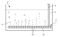
- FIG. 19 shows an example of such an aeration tank.
- Water W to be treated is stored in the tank 1, and an air diffuser 2 is installed near the bottom of the tank 1.
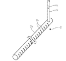
- the air diffuser 2 is, for example, a device as shown in FIG. 20, so that the gas (in this case, air) A is sent into the main body 2a from the air guide tube 3 connected to one end of the hollow main body 2a. It has become.
- the main body 2a is a pipe having a space inside, and a large number of air diffusers 2b communicating inside and outside are provided on the side surface thereof.
- the air A sent from the air guide tube 3 into the main body 2a is discharged as bubbles from the air diffuser holes 2b to the water W.
- the air A is brought into contact with the water W to dissolve oxygen in the water W, and the water W stored in the tank 1 is agitated by the movement of bubbles so that the dissolved oxygen is supplied to the entire tank 1. It has become.
- Patent Document 1 is a document that describes a technique related to such an air diffuser.
- the above-mentioned air diffuser is not limited to sewage treatment facilities, but is used for all equipment that allows living organisms to survive in the water stored in the tank. Even in such equipment, oxygen can be efficiently supplied with less energy. It goes without saying that it is desirable to supply.
- gas components other than oxygen such as carbon dioxide
- the gas supply efficiency total amount of gas sent.
- the ratio of the amount of a specific gas component supplied to water to water is preferably as high as possible.
- the present invention is intended to provide an air diffuser capable of efficiently supplying gas to water.
- a bottom panel provided along the horizontal direction in a tank for storing water, a gas diffuser installed so as to cover the upper side of the bottom panel, and a diffuser provided so as to penetrate the gas diffuser. It is configured to have pores and to discharge the gas sent between the bottom panel and the gas diffuser into water through the air diffuser, and the width of the air diffuser region provided with the air diffuser in the gas diffuser is 10 mm or more. It applies to an air diffuser characterized by being less than 120 mm.
- the air diffuser may be configured to be provided over the entire width direction of the gas diffuser.
- the air diffuser may be provided in a part of the region in the width direction of the gas diffuser.
- the air diffuser of the present invention it is possible to exert an excellent effect that gas can be efficiently supplied to water.
- (C) shows the case where the width of the air diffuser region is set to 60 mm.
- sectional drawing shows the schematic structure of the tank provided with the air diffuser.
- It is a perspective view which shows an example of the form of the air diffuser.
- FIGS. 1 to 4 show an example of the form of the air diffuser according to the implementation of the present invention.
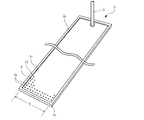
- the air diffuser 4 of the first embodiment is installed near the bottom of the tank 1 like the air diffuser 2 of the conventional example shown in FIGS. 19 and 20, and provides air A supplied from the air guide tube 3. It is designed to be sent to the water W stored in the tank 1.
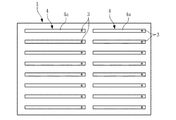
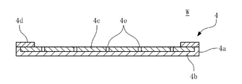
- the air diffuser 4 includes a rectangular main body 4a.
- the main body 4a is provided in the tank 1 along the horizontal direction, and includes a bottom panel 4b forming the bottom surface of the main body 4a and a gas diffuser 4c installed so as to cover the upper side of the bottom panel 4b.
- the bottom panel 4b is formed of a hard material such as stainless steel, and the dusting gas 4c is formed as a soft film.
- a frame 4d is provided on the upper surfaces of the four sides of the bottom panel 4b, and the dusting gas 4c is held by the bottom panel 4b so that the four sides are sandwiched between the bottom panel 4b and the frame 4d.
- the film-shaped diffuser 4c is provided with a large number of air diffuser holes 4e so as to penetrate the diffuser 4c from the front to the back over the entire width direction of the diffuser 4c. Further, an air guide tube 3 is connected to the end portion of the gas diffuser 4c in the longitudinal direction, and air A is sent from the air guide tube 3 between the gas diffuser 4c and the bottom panel 4b.
- FIG. 3 shows only a part of the air diffuser holes 4e for convenience of drawing. Further, the air diffuser holes 4e in FIGS. 3 and 4 are merely schematically shown, and the actual pore diameter and spacing of the air diffuser holes 4e, the thickness of the gas diffuser 4c, and the like are various conditions at the time of implementation. It can be changed as appropriate according to the above (the same applies to FIGS. 5, 6 and 10).
- the air A is discharged into the water W in the form of bubbles from the air diffuser 4e during use, while the air diffuser 4e closes to prevent the water W from entering the inside when not in use, and prevents clogging inside the main body 4a. It is designed to do. If the air diffuser 4e is clogged when not in use, the air A is repeatedly supplied and stopped, and the solid matter is pushed out from the air diffuser 4e due to the deformation of the gas diffuser 4c and the pressure of the air A. The clogging can be removed in this way.
- the width of the range in which the air diffuser holes 4e are provided (hereinafter referred to as the air diffuser region R), that is, the dimension in the lateral direction (shown as the width D in FIG.
- the value of is the dimension in which the diffuser 4c is in close contact with the bottom panel 4b) is preferably 10 mm or more and less than 120 mm as described later, but is 60 mm in the first embodiment. ..
- the length of the main body 4a that is, the dimension in the longitudinal direction (shown as the length L in FIG. 3) can be appropriately changed according to conditions such as the size of the installation location, for example, about 0.5 m to 4 m. Is.
- FIG. 6 shows an air diffuser 4 in which the width D of the air diffuser region R is set to 120 mm as a reference example of the present invention
- FIGS. 7 and 8 show the reference example shown in FIG. 6 and FIGS.
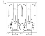
- the air diffuser 4 of the first embodiment shown in FIG. 5 the movements of the air A and the water W during operation are schematically shown.
- a reference example in which only one air diffuser 4 having a width D of 120 mm in the air diffuser area R (see FIGS. 3 and 6) is provided for the tank 1 having the same width, and a reference example (see FIG. 7) having a width D of 60 mm.
- the area of the air diffuser R is the same (note that the number of air diffusers 4 per tank shown here is described.
- the number of air diffusers installed per tank 1 is usually larger than the number shown in FIGS. 7 and 8. Is).
- the same total amount of air A is sent to the air diffuser 4 of these reference examples and the first embodiment, in the first embodiment, more oxygen is dissolved in the water W as compared with the reference example. You can do it.
- the tank 1 As the tank 1, a cylindrical one having an inner diameter of 774 mm is used, and water W is filled therein at a depth of 5.1 m, and a plurality of air diffusers 4 are installed near the bottom surface (height of a water depth of 5.0 m). did.
- FIG. 2 an aeration system in which the air diffuser 4 is evenly arranged on the bottom surface of the tank 1 is adopted, and air A is supplied to each air diffuser 4.
- the length L (see FIG. 3) was set to 600 mm
- the length of the air diffuser region R (dimensions in the direction orthogonal to the width D) was set to 400 mm.
- the width D of the air-dissipating area R differs depending on the conditions, but even if the width D of the air-dissipating area R in each air-dissipating device 4 is different, the total area of the air-dissipating area R occupied in the tank 1 is equal. Adjusted the number of air diffusers installed. The ratio of the air-dissipating region R to the bottom area of the tank 1 was set to 12.8%.
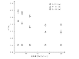
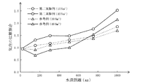
- the horizontal axis is the amount of air blown (total amount of air blown to the air diffuser 4 per unit time and unit projected area in the diffused gas 4c [Nm3 / (m2 ⁇ hr)], and the vertical axis is oxygen dissolution under each condition.
- the relative value of the efficiency (relative value where the oxygen dissolution efficiency when the width D is 150 mm is 1) is shown. Under the three conditions (37.5 mm, 50 mm and 75 mm) in which the width D is set smaller than 120 mm, the width D is shown.
- the oxygen dissolution efficiency was remarkably improved (about 1.1 to 1.25 times) as compared with the case of 150 mm, which exceeds 120 mm, and the smaller the width D, the higher the oxygen dissolution efficiency.
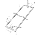
- FIG. 10 shows the air diffuser 4 according to the second embodiment of the present invention.
- the dimensions of the bottom panel 4b, the frame 4d, and the gas diffuser 4c as a whole are the same as those of the reference example shown in FIG. It is provided only in the area. That is, the overall dimensions are the same as in the reference example, but the width D of the air diffuser region R is 60 mm, which is the same as in the first embodiment.
- the same parts as in the reference example are used for the bottom panel 4b and the frame 4d, and the gas diffuser 4c in which only the arrangement of the air diffuser holes 4e is changed is used, so that the same parts as in the first embodiment as described above are used. The action effect can be obtained.
- the position where the air diffuser 4e is provided is not limited to the center, and the air diffuser 4e is provided in a part of the region in the width direction. It suffices if it is provided. For example, it may be a position closer to both ends or one end in the width direction.
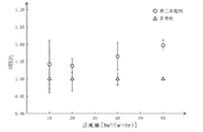
- FIG. 11 shows the results of an experiment in which the oxygen dissolution efficiency in water W was verified for each of the air diffuser 4 of the reference example (see FIG. 7) and the second embodiment (see FIG. 10).
- an air diffuser 4 having a width D set to 60 mm and 120 mm was used, and the same amount of air A per unit projected area was sent to each air diffuser 4, and oxygen dissolved in water W was supplied. The amount was measured.
- a tank 1 having an inner dimension of 5 m ⁇ 5 m is used, and water W is filled therein at a depth of 5.1 m, and a plurality of air diffusers are provided near the bottom surface (height of a water depth of 5.0 m).
- 4 was installed. Air A was supplied to each air diffuser 4 by a full-scale aeration method in which the air diffuser 4 was evenly arranged on the bottom surface of the tank 1. The length of the air diffuser region R in each air diffuser 4 was set to 2 m. Further, the number of installed air diffusers was adjusted so that the total area of the air diffusers R occupied in the tank 1 was the same even if the width D of the air diffusers R in each air diffuser 4 was different. The ratio of the air-dissipating region R to the bottom area of the tank 1 was set to 11.5%.
- the horizontal axis is the total amount of air blown to the air diffuser 4 per unit time and unit projected area in the diffuser 4c [Nm3 / (m2 ⁇ hr)], and the vertical axis is the relative value of oxygen dissolution efficiency (same blowing). It is a relative value with the oxygen dissolution efficiency as 1 in the reference example of the air volume), the triangular symbol indicates the reference example, and the circular symbol indicates the second embodiment. It can be seen that the oxygen dissolution efficiency in the second example is about 1.04 to 1.1 times higher than that in the reference example under each condition.
- the supply amount of air A per unit air diffuser 4 is smaller than that of the reference example (FIG. 7) (assuming the total supply amount is 2Qa, the air diffuser 4).
- the buoyancy applied to the bubbles is weak by that amount, and the rising speed of the bubbles is originally slow.
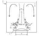
- Water W circulates as the bubbles rise, as shown by the black arrows in FIGS. 7 and 8. That is, on the air diffuser 4, the water W rises as the bubbles rise (indicated by white arrows), but reverses near the water surface and descends at a position away from the air diffuser 4 in the width direction. Then, when it approaches the air diffuser 4, it reverses again and rises with air bubbles.
- the rising speed of the bubbles in the vicinity of the air diffuser 4 is slow, the movement of the water W in this region is also slow, and in particular, the velocity component in the horizontal direction toward the air diffuser 4 (shown as Vh in FIGS. 7 and 8). ) Becomes smaller.
- the bubbles released from the air diffuser 4 are not concentrated in a narrow area in the tank 1 as much as possible, and the oxygen dissolution efficiency is higher when they are distributed over a wide area.
- the movement of the water W approaching the air diffuser 4 works to gather the bubbles released from the air diffuser 4. Therefore, if the velocity component Vh in the horizontal direction is small, the distribution area of bubbles in the tank 1 becomes wide. That is, the ratio (wa / D; hereinafter, bubbles) of the width of the distribution area of the bubbles (shown as wa in FIGS. 7 and 8) at a certain height above the air diffuser 4 with respect to the width D of the air diffuser region R. In the second embodiment, it is larger than that in the reference example.
- FIG. 12 shows the results of an experiment in which the width of the distribution area of bubbles was verified.
- 10 N / m 3 or 40 N / m 3 of air A is supplied per 1 m 2 of the projected area in the diffused gas 4c in total, and each diffuser is supplied.
- the diffusion ratio wa / D of the bubbles at the height direction distance (water depth distance) from the air device 4 was measured.
- the diffusion ratio of bubbles was larger in the second example than in the reference example under each condition.
- the diffusion ratio of the bubbles became smaller than 1.0 in the reference example (that is, the air bubbles released from the air diffuser 4 caused the movement of the water W.
- the air bubble distribution area was gathered at any measured height.
- the width wa was wider than the width D of the diffusion region.
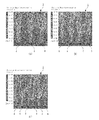
- FIGS. 13 to 15 show the results of simulating the distribution of the flow velocity vector of water W, the concentration distribution of bubbles, and the horizontal flow velocity of water W in the tank 1 with respect to the reference example and the embodiment of the present invention.
- the air diffuser 4 in addition to the reference example (see FIG. 6) and the first embodiment (see FIG. 3), the air diffuser 4 (see FIG. 10) of the second embodiment of the present invention is used. was also verified.
- the air diffuser 5 having a shape similar to that of the conventional air diffuser 2 shown in FIG. 20 was also verified and compared with each example.
- the air diffuser 5 according to this another reference example includes a central body having a cylindrical shape and extending along the horizontal direction, and a film-like gas diffuser provided so as to cover the circumferential surface of the central body.
- the gas diffuser is provided with air diffuser holes on both sides. Then, air is sent between the centrosome and the gas diffuser, and is discharged to the outside from the air diffuser holes on both sides.
- the diameter of the cylindrical air diffuser 5 including the gas diffuser and the centrosome is 66 mm in the stopped state of air supply, and the width (circumference) of the air diffuser region arranged on both side surfaces along the cylindrical surface of the centrosome.
- the dimensions in the direction) are 60 mm (120 mm in total).
- the simulation conditions were set as follows.
- the inner wall of the tank 1 has a width and a depth of 1.4 m, respectively, and a water depth of 1.4 m.
- the dimension of each air diffuser in the longitudinal direction (corresponding to the length L in FIG. 3) is 1.2 m, and is arranged at a height of 0.1 m from the bottom surface of the tank 1 so that the longitudinal direction is along the depth direction. Will be done.
- the number of installed air diffusers is one in the reference example and another reference example, and two in the first and second embodiments. That is, the total area of the air-dissipating area per bottom area of the tank 1 was set to be the same in each reference example and each embodiment.
- the air volume was 40 Nm 3 / (m 2 ⁇ hr).
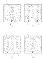
- FIG. 13 is a simplified diagram showing the result of simulating the distribution of the flow velocity vector of water W in the tank 1 in which the air diffuser 4 of the reference example and each embodiment is installed.
- the rising speed of water W above each air diffuser 4 is slower. This is considered to reflect the magnitude of the rising rate of the bubbles as described above.
- (D) shows the flow velocity vector of water W at the time of operation of the air diffuser 5 according to another reference example.
- the width (dimensions in the circumferential direction) of each region (corresponding to the air diffuser R in each Example and Reference Example) provided with air diffusers arranged on both side surfaces is the above-mentioned first and Although it is equal to the air diffuser 4 of the second embodiment and smaller than the reference example, the flow velocity vector of the water W going upward from the air diffuser 5 is very large, and the flow velocity vector of the water W shown in (A) is very large. Even bigger than the case.
- the bubbles released from the air diffusers provided on the side surfaces of the main body associate with each other while rising along the side surfaces, thereby increasing the buoyancy. That is, in the case of the air diffuser 2 of this other reference example, the bubbles released into the water W are larger than those of the air diffuser 4 of the reference example as well as the first and second embodiments. turn into. As a result, the oxygen dissolution efficiency is considered to be significantly inferior to that of the reference example and each example.
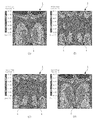
- FIG. 14 shows the concentration distribution of bubbles in the tank 1.
- the concentration of bubbles in the immediate vicinity of the air diffuser 4 is very high, and the region where the concentration of bubbles is relatively high is widely distributed even near the water surface. In such a region where the concentration of bubbles is high, it is considered that there are many opportunities for the bubbles to meet with each other.
- the distribution of the region where the concentration of bubbles is high is (A). ) Is narrower than the reference example shown.
- the region where the concentration of bubbles is high extends long upward from the left and right side surfaces of the main body, and many bubble associations occur here.
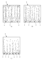
- FIG. 15 shows the distribution of the horizontal flow velocity of water W in the tank 1.
- a region having a high flow velocity in the horizontal direction extends around the immediate vicinity of the air diffuser 4, and this is the width of the distribution region of bubbles as shown in FIG. 12 or FIG. 14 (A).
- the region where the flow velocity in the horizontal direction is high is narrower than that in the reference example shown in (A).
- the region where the flow velocity in the horizontal direction is high is wider than that in the reference example shown in (A).
- the width D of the air diffuser region R in each air diffuser 4 is preferably set to 10 mm or more and less than 120 mm, more preferably 30 mm or more and 90 mm or less.
- the effect described above is considered to be more effective as the width D is narrower, but on the other hand, it is necessary to secure a certain width in the frame 4d for holding the diffuser 4c due to its structure. Therefore, when trying to secure the required area of the air diffuser region R for the entire tank 1, if the width D of the air diffuser region R in each air diffuser 4 is too narrow, the frame 4d is compared with the air diffuser region R.
- the width D of the air diffuser region R in each air diffuser 4 is preferably 10 mm to 30 mm or more as described above.
- FIG. 16 to 18 show the relationship between the width D of the air diffuser region R, the distribution of the flow velocity vector of water W in the tank 1, the concentration distribution of bubbles, and the horizontal flow velocity of water W. This is the result of simulating by further changing the number of air devices arranged.
- (A) is a case where an air diffuser 4 (corresponding to the above reference example) in which the width D of the air diffuser region R is set to 120 mm is installed, and (B) is an air diffuser in which the width D is set to 90 mm.
- (C) shows the case where 4 is installed, and (C) shows the case where the air diffuser 4 (corresponding to the first embodiment) in which the width D is set to 60 mm is installed.
- the number of each air diffuser 4 installed in the tank 1 is 3 in each figure (A), 4 in (B), and 6 in (C), and the air diffuser area per bottom area of the tank 1 is set. The total area of is set to be the same.
- FIG. 17 shows the concentration distribution of bubbles in the tank 1. In (A), the concentration of bubbles in the immediate vicinity of the air diffuser 4 is very high, whereas in (B) and (C), the bubbles are very high. The distribution of the region where the concentration of is high is narrower than that of the reference example shown in (A).
- the air diffuser 4 of each of the above embodiments is installed so as to cover the bottom panel 4b provided along the horizontal direction in the tank 1 for storing the water W and the upper side of the bottom panel 4b.
- a gas 4c and a gas diffuser 4e provided so as to penetrate the gas diffuser 4c are provided, and the gas (air) A sent between the bottom panel 4b and the gas diffuser 4c is discharged into the water W through the air diffuser 4e.
- the width D of the air diffuser region R provided with the air diffuser holes 4e in the gas diffuser 4c is set to 10 mm or more and less than 120 mm.
- the air diffuser 4e can be configured to be provided over the entire width direction of the gas diffuser 4c.
- the air diffuser 4e may be provided in a part of the region in the width direction of the gas diffuser 4c.
- the gas can be efficiently supplied to water.
- air diffuser of the present invention is not limited to the above-described embodiment, and it goes without saying that various modifications can be made without departing from the gist of the present invention.
Abstract
Description
4 散気装置
4b 底パネル
4c 散気体
4e 散気孔
A 気体(空気)
D 幅
R 散気領域
W 水 1
D width R diffuser area W water
Claims (3)
- 水を貯留する槽内に水平方向に沿って設けられる底パネルと、
前記底パネルの上側を覆うように設置された散気体と、
前記散気体を貫通するように設けられた散気孔を備え、
前記底パネルと前記散気体の間に送り込まれた気体を前記散気孔を通して水中に放出するよう構成され、
前記散気体における前記散気孔を設けられた散気領域の幅は10mm以上120mm未満であることを特徴とする散気装置。 A bottom panel provided along the horizontal direction in the tank that stores water,
With the gas diffuser installed so as to cover the upper side of the bottom panel,
It is provided with an air diffuser hole provided so as to penetrate the diffuser.
The gas sent between the bottom panel and the gas diffuser is configured to be discharged into the water through the air diffuser.
An air diffuser having a width of 10 mm or more and less than 120 mm in the air diffuser region provided with the air diffuser holes in the gas diffuser. - 前記散気孔は、前記散気体における幅方向の全域にわたって設けられていることを特徴とする請求項1に記載の散気装置。 The air diffuser according to claim 1, wherein the air diffuser is provided over the entire width direction of the gas diffuser.
- 前記散気孔は、前記散気体における幅方向に関して一部の領域に設けられていることを特徴とする請求項1に記載の散気装置。 The air diffuser according to claim 1, wherein the air diffuser is provided in a part of a region in the width direction of the gas diffuser.
Priority Applications (5)
| Application Number | Priority Date | Filing Date | Title |
|---|---|---|---|
| US17/763,008 US20220347636A1 (en) | 2019-09-25 | 2020-09-24 | Air diffuser |
| AU2020353550A AU2020353550B9 (en) | 2019-09-25 | 2020-09-24 | Air diffuser |
| KR1020227008003A KR102601504B1 (en) | 2019-09-25 | 2020-09-24 | diffuser device |
| EP20869566.8A EP4035765A4 (en) | 2019-09-25 | 2020-09-24 | Air diffuser |
| CN202080065540.1A CN114466826A (en) | 2019-09-25 | 2020-09-24 | Air diffusing device |
Applications Claiming Priority (2)
| Application Number | Priority Date | Filing Date | Title |
|---|---|---|---|
| JP2019-174346 | 2019-09-25 | ||
| JP2019174346A JP2021049499A (en) | 2019-09-25 | 2019-09-25 | Air diffuser |
Publications (1)
| Publication Number | Publication Date |
|---|---|
| WO2021060417A1 true WO2021060417A1 (en) | 2021-04-01 |
Family
ID=75156278
Family Applications (1)
| Application Number | Title | Priority Date | Filing Date |
|---|---|---|---|
| PCT/JP2020/036138 WO2021060417A1 (en) | 2019-09-25 | 2020-09-24 | Air diffuser |
Country Status (7)
| Country | Link |
|---|---|
| US (1) | US20220347636A1 (en) |
| EP (1) | EP4035765A4 (en) |
| JP (1) | JP2021049499A (en) |
| KR (1) | KR102601504B1 (en) |
| CN (1) | CN114466826A (en) |
| AU (1) | AU2020353550B9 (en) |
| WO (1) | WO2021060417A1 (en) |
Citations (4)
| Publication number | Priority date | Publication date | Assignee | Title |
|---|---|---|---|---|
| JP2003024974A (en) * | 2001-07-13 | 2003-01-28 | Ngk Insulators Ltd | Air diffusing device and aeration tank using the same |
| JP2011230068A (en) * | 2010-04-28 | 2011-11-17 | Ael:Kk | Air diffusing body |
| JP2016002499A (en) * | 2014-06-13 | 2016-01-12 | 住友重機械エンバイロメント株式会社 | Air diffusion plate, air diffusion device, and mounting method of air diffusion plate |
| JP2016198700A (en) * | 2015-04-08 | 2016-12-01 | 日東電工株式会社 | Aeration member, aeration plate and aeration device |
Family Cites Families (19)
| Publication number | Priority date | Publication date | Assignee | Title |
|---|---|---|---|---|
| US2978234A (en) * | 1951-01-16 | 1961-04-04 | Fmc Corp | Diffuser tube |
| DE3474949D1 (en) * | 1984-08-16 | 1988-12-08 | Rudolf Messner | Fine-bubble diffuser for aeration of water |
| DE9006868U1 (en) * | 1990-06-19 | 1990-10-04 | Venator Inc., Victor, Id., Us | |
| US5133862A (en) * | 1991-01-31 | 1992-07-28 | Fmc Corporation | Flexible membrane diffuser |
| CH685627A5 (en) * | 1992-08-31 | 1995-08-31 | Bontec Ag | Gas distributor for fine bubble aeration of water. |
| US5858283A (en) * | 1996-11-18 | 1999-01-12 | Burris; William Alan | Sparger |
| EP0947471A1 (en) * | 1998-03-03 | 1999-10-06 | Huber + Suhner AG Kabel-, Kautschuk-, Kunststoffwerke | Aerating device for water and method for manufacturing an aerator |
| AT409623B (en) * | 1999-04-28 | 2002-09-25 | Aquaconsult Anlagenbau Gmbh | flotation |
| US6841083B2 (en) * | 2002-06-27 | 2005-01-11 | Ethicon, Inc. | Device and process for improved scouring efficiency |
| US7255333B2 (en) * | 2002-08-13 | 2007-08-14 | Itt Manufacturing Enterprises, Inc. | Strip diffuser |
| KR200321616Y1 (en) * | 2003-04-16 | 2003-07-31 | 주식회사 신일 | Spreading Appartus for produce Microscopic Air Bubble |
| US7806389B2 (en) * | 2005-10-26 | 2010-10-05 | Parkson Corporation | Flexible aeration panel and methods of use |
| US8002248B2 (en) * | 2008-06-19 | 2011-08-23 | Kang Na Hsiung Enterprise Co., Ltd. | Diffuser for an aeration system |
| US20130154132A1 (en) * | 2011-12-05 | 2013-06-20 | Parkson Corporation | Liftable aeration assembly and methods of placing an aeration assembly into a receptacle |
| KR101266507B1 (en) * | 2012-11-19 | 2013-05-27 | (주)에이엔티이십일 | Air diffuser |
| DE102013106845B4 (en) * | 2013-07-01 | 2017-06-14 | NORRES Beteiligungs-GmbH | Device for distributing gases in liquids |
| US9862628B2 (en) * | 2013-10-04 | 2018-01-09 | Ovivo Inc. | Adjustable variable bubble size aeration for submerged membrane air scour |
| JP6246610B2 (en) * | 2014-02-12 | 2017-12-13 | 三機工業株式会社 | Air diffuser |
| AU2018340870A1 (en) * | 2017-09-29 | 2020-04-30 | Aquatec Maxcon Pty Ltd | Diffuser for aeration of a fluid |
-
2019
- 2019-09-25 JP JP2019174346A patent/JP2021049499A/en active Pending
-
2020
- 2020-09-24 EP EP20869566.8A patent/EP4035765A4/en active Pending
- 2020-09-24 KR KR1020227008003A patent/KR102601504B1/en active IP Right Grant
- 2020-09-24 WO PCT/JP2020/036138 patent/WO2021060417A1/en unknown
- 2020-09-24 AU AU2020353550A patent/AU2020353550B9/en active Active
- 2020-09-24 CN CN202080065540.1A patent/CN114466826A/en active Pending
- 2020-09-24 US US17/763,008 patent/US20220347636A1/en active Pending
Patent Citations (4)
| Publication number | Priority date | Publication date | Assignee | Title |
|---|---|---|---|---|
| JP2003024974A (en) * | 2001-07-13 | 2003-01-28 | Ngk Insulators Ltd | Air diffusing device and aeration tank using the same |
| JP2011230068A (en) * | 2010-04-28 | 2011-11-17 | Ael:Kk | Air diffusing body |
| JP2016002499A (en) * | 2014-06-13 | 2016-01-12 | 住友重機械エンバイロメント株式会社 | Air diffusion plate, air diffusion device, and mounting method of air diffusion plate |
| JP2016198700A (en) * | 2015-04-08 | 2016-12-01 | 日東電工株式会社 | Aeration member, aeration plate and aeration device |
Non-Patent Citations (1)
| Title |
|---|
| See also references of EP4035765A4 * |
Also Published As
| Publication number | Publication date |
|---|---|
| AU2020353550B2 (en) | 2023-07-27 |
| US20220347636A1 (en) | 2022-11-03 |
| AU2020353550A1 (en) | 2022-04-07 |
| KR20220075311A (en) | 2022-06-08 |
| JP2021049499A (en) | 2021-04-01 |
| EP4035765A4 (en) | 2023-10-18 |
| EP4035765A1 (en) | 2022-08-03 |
| KR102601504B1 (en) | 2023-11-14 |
| CN114466826A (en) | 2022-05-10 |
| AU2020353550B9 (en) | 2023-11-23 |
Similar Documents
| Publication | Publication Date | Title |
|---|---|---|
| JP2008212788A (en) | Cleaning apparatus and cleaning method | |
| KR930702065A (en) | Aeration of liquid | |
| JP2016028806A (en) | Air diffuser, and water treatment apparatus and method for operating the same | |
| WO2021060417A1 (en) | Air diffuser | |
| JPH10229781A (en) | Method and device for deffusing air into water | |
| JP5835776B2 (en) | Air diffuser | |
| WO2012108008A1 (en) | Membrane air diffuser | |
| JP2012170946A (en) | Air diffusion cylinder, and aerobic tank provided therewith | |
| JPH0545440Y2 (en) | ||
| KR101971427B1 (en) | Aeration system | |
| JP3437966B1 (en) | Fluid supply pipe and wastewater treatment apparatus provided with the fluid supply pipe | |
| KR20200102748A (en) | An Air Diffuser For Oxygen Supply | |
| JPH06335699A (en) | Device for purifying closed water basin | |
| JP2013226525A (en) | Membrane for air diffusion device | |
| JP2020014999A (en) | Air diffusion device | |
| JP5358714B2 (en) | Biological treatment method and biological treatment apparatus | |
| KR20190095742A (en) | Gas dissolving apparatus | |
| JP7474602B2 (en) | Gas-liquid dispersion device | |
| JP5334741B2 (en) | Membrane diffuser | |
| JP3207607U (en) | Rectifier | |
| KR102146876B1 (en) | High efficiency bioactive foam reactor incorporated in turbulent, dispersion and diffusion of fluid | |
| JP4215669B2 (en) | Aquaculture equipment | |
| JPH0535012B2 (en) | ||
| JP2021090966A (en) | Water treatment system and method for improving water treatment system | |
| JP2017070897A (en) | Aeration operation method |
Legal Events
| Date | Code | Title | Description |
|---|---|---|---|
| 121 | Ep: the epo has been informed by wipo that ep was designated in this application |
Ref document number: 20869566 Country of ref document: EP Kind code of ref document: A1 |
|
| NENP | Non-entry into the national phase |
Ref country code: DE |
|
| ENP | Entry into the national phase |
Ref document number: 2020353550 Country of ref document: AU Date of ref document: 20200924 Kind code of ref document: A |
|
| ENP | Entry into the national phase |
Ref document number: 2020869566 Country of ref document: EP Effective date: 20220425 |