WO2021059836A1 - Container and inspection kit - Google Patents
Container and inspection kit Download PDFInfo
- Publication number
- WO2021059836A1 WO2021059836A1 PCT/JP2020/032201 JP2020032201W WO2021059836A1 WO 2021059836 A1 WO2021059836 A1 WO 2021059836A1 JP 2020032201 W JP2020032201 W JP 2020032201W WO 2021059836 A1 WO2021059836 A1 WO 2021059836A1
- Authority
- WO
- WIPO (PCT)
- Prior art keywords
- accommodating portion
- flow path
- container
- liquid
- magnetic particles
- Prior art date
Links
Images


Classifications
-
- B—PERFORMING OPERATIONS; TRANSPORTING
- B01—PHYSICAL OR CHEMICAL PROCESSES OR APPARATUS IN GENERAL
- B01L—CHEMICAL OR PHYSICAL LABORATORY APPARATUS FOR GENERAL USE
- B01L3/00—Containers or dishes for laboratory use, e.g. laboratory glassware; Droppers
- B01L3/50—Containers for the purpose of retaining a material to be analysed, e.g. test tubes
- B01L3/502—Containers for the purpose of retaining a material to be analysed, e.g. test tubes with fluid transport, e.g. in multi-compartment structures
- B01L3/5027—Containers for the purpose of retaining a material to be analysed, e.g. test tubes with fluid transport, e.g. in multi-compartment structures by integrated microfluidic structures, i.e. dimensions of channels and chambers are such that surface tension forces are important, e.g. lab-on-a-chip
- B01L3/502761—Containers for the purpose of retaining a material to be analysed, e.g. test tubes with fluid transport, e.g. in multi-compartment structures by integrated microfluidic structures, i.e. dimensions of channels and chambers are such that surface tension forces are important, e.g. lab-on-a-chip specially adapted for handling suspended solids or molecules independently from the bulk fluid flow, e.g. for trapping or sorting beads, for physically stretching molecules
-
- B—PERFORMING OPERATIONS; TRANSPORTING
- B01—PHYSICAL OR CHEMICAL PROCESSES OR APPARATUS IN GENERAL
- B01L—CHEMICAL OR PHYSICAL LABORATORY APPARATUS FOR GENERAL USE
- B01L3/00—Containers or dishes for laboratory use, e.g. laboratory glassware; Droppers
- B01L3/50—Containers for the purpose of retaining a material to be analysed, e.g. test tubes
- B01L3/502—Containers for the purpose of retaining a material to be analysed, e.g. test tubes with fluid transport, e.g. in multi-compartment structures
- B01L3/5023—Containers for the purpose of retaining a material to be analysed, e.g. test tubes with fluid transport, e.g. in multi-compartment structures with a sample being transported to, and subsequently stored in an absorbent for analysis
-
- B—PERFORMING OPERATIONS; TRANSPORTING
- B01—PHYSICAL OR CHEMICAL PROCESSES OR APPARATUS IN GENERAL
- B01L—CHEMICAL OR PHYSICAL LABORATORY APPARATUS FOR GENERAL USE
- B01L3/00—Containers or dishes for laboratory use, e.g. laboratory glassware; Droppers
- B01L3/50—Containers for the purpose of retaining a material to be analysed, e.g. test tubes
- B01L3/502—Containers for the purpose of retaining a material to be analysed, e.g. test tubes with fluid transport, e.g. in multi-compartment structures
- B01L3/5027—Containers for the purpose of retaining a material to be analysed, e.g. test tubes with fluid transport, e.g. in multi-compartment structures by integrated microfluidic structures, i.e. dimensions of channels and chambers are such that surface tension forces are important, e.g. lab-on-a-chip
- B01L3/502715—Containers for the purpose of retaining a material to be analysed, e.g. test tubes with fluid transport, e.g. in multi-compartment structures by integrated microfluidic structures, i.e. dimensions of channels and chambers are such that surface tension forces are important, e.g. lab-on-a-chip characterised by interfacing components, e.g. fluidic, electrical, optical or mechanical interfaces
-
- B—PERFORMING OPERATIONS; TRANSPORTING
- B01—PHYSICAL OR CHEMICAL PROCESSES OR APPARATUS IN GENERAL
- B01L—CHEMICAL OR PHYSICAL LABORATORY APPARATUS FOR GENERAL USE
- B01L3/00—Containers or dishes for laboratory use, e.g. laboratory glassware; Droppers
- B01L3/50—Containers for the purpose of retaining a material to be analysed, e.g. test tubes
- B01L3/502—Containers for the purpose of retaining a material to be analysed, e.g. test tubes with fluid transport, e.g. in multi-compartment structures
- B01L3/5027—Containers for the purpose of retaining a material to be analysed, e.g. test tubes with fluid transport, e.g. in multi-compartment structures by integrated microfluidic structures, i.e. dimensions of channels and chambers are such that surface tension forces are important, e.g. lab-on-a-chip
- B01L3/502746—Containers for the purpose of retaining a material to be analysed, e.g. test tubes with fluid transport, e.g. in multi-compartment structures by integrated microfluidic structures, i.e. dimensions of channels and chambers are such that surface tension forces are important, e.g. lab-on-a-chip characterised by the means for controlling flow resistance, e.g. flow controllers, baffles
-
- C—CHEMISTRY; METALLURGY
- C12—BIOCHEMISTRY; BEER; SPIRITS; WINE; VINEGAR; MICROBIOLOGY; ENZYMOLOGY; MUTATION OR GENETIC ENGINEERING
- C12Q—MEASURING OR TESTING PROCESSES INVOLVING ENZYMES, NUCLEIC ACIDS OR MICROORGANISMS; COMPOSITIONS OR TEST PAPERS THEREFOR; PROCESSES OF PREPARING SUCH COMPOSITIONS; CONDITION-RESPONSIVE CONTROL IN MICROBIOLOGICAL OR ENZYMOLOGICAL PROCESSES
- C12Q1/00—Measuring or testing processes involving enzymes, nucleic acids or microorganisms; Compositions therefor; Processes of preparing such compositions
- C12Q1/68—Measuring or testing processes involving enzymes, nucleic acids or microorganisms; Compositions therefor; Processes of preparing such compositions involving nucleic acids
- C12Q1/6806—Preparing nucleic acids for analysis, e.g. for polymerase chain reaction [PCR] assay
-
- G—PHYSICS
- G01—MEASURING; TESTING
- G01N—INVESTIGATING OR ANALYSING MATERIALS BY DETERMINING THEIR CHEMICAL OR PHYSICAL PROPERTIES
- G01N1/00—Sampling; Preparing specimens for investigation
- G01N1/02—Devices for withdrawing samples
- G01N1/10—Devices for withdrawing samples in the liquid or fluent state
-
- G—PHYSICS
- G01—MEASURING; TESTING
- G01N—INVESTIGATING OR ANALYSING MATERIALS BY DETERMINING THEIR CHEMICAL OR PHYSICAL PROPERTIES
- G01N30/00—Investigating or analysing materials by separation into components using adsorption, absorption or similar phenomena or using ion-exchange, e.g. chromatography or field flow fractionation
- G01N30/02—Column chromatography
- G01N30/88—Integrated analysis systems specially adapted therefor, not covered by a single one of the groups G01N30/04 - G01N30/86
-
- G—PHYSICS
- G01—MEASURING; TESTING
- G01N—INVESTIGATING OR ANALYSING MATERIALS BY DETERMINING THEIR CHEMICAL OR PHYSICAL PROPERTIES
- G01N33/00—Investigating or analysing materials by specific methods not covered by groups G01N1/00 - G01N31/00
- G01N33/48—Biological material, e.g. blood, urine; Haemocytometers
- G01N33/50—Chemical analysis of biological material, e.g. blood, urine; Testing involving biospecific ligand binding methods; Immunological testing
- G01N33/52—Use of compounds or compositions for colorimetric, spectrophotometric or fluorometric investigation, e.g. use of reagent paper and including single- and multilayer analytical elements
- G01N33/521—Single-layer analytical elements
-
- G—PHYSICS
- G01—MEASURING; TESTING
- G01N—INVESTIGATING OR ANALYSING MATERIALS BY DETERMINING THEIR CHEMICAL OR PHYSICAL PROPERTIES
- G01N33/00—Investigating or analysing materials by specific methods not covered by groups G01N1/00 - G01N31/00
- G01N33/48—Biological material, e.g. blood, urine; Haemocytometers
- G01N33/50—Chemical analysis of biological material, e.g. blood, urine; Testing involving biospecific ligand binding methods; Immunological testing
- G01N33/53—Immunoassay; Biospecific binding assay; Materials therefor
- G01N33/543—Immunoassay; Biospecific binding assay; Materials therefor with an insoluble carrier for immobilising immunochemicals
- G01N33/54313—Immunoassay; Biospecific binding assay; Materials therefor with an insoluble carrier for immobilising immunochemicals the carrier being characterised by its particulate form
- G01N33/54326—Magnetic particles
-
- G—PHYSICS
- G01—MEASURING; TESTING
- G01N—INVESTIGATING OR ANALYSING MATERIALS BY DETERMINING THEIR CHEMICAL OR PHYSICAL PROPERTIES
- G01N37/00—Details not covered by any other group of this subclass
-
- B—PERFORMING OPERATIONS; TRANSPORTING
- B01—PHYSICAL OR CHEMICAL PROCESSES OR APPARATUS IN GENERAL
- B01L—CHEMICAL OR PHYSICAL LABORATORY APPARATUS FOR GENERAL USE
- B01L2200/00—Solutions for specific problems relating to chemical or physical laboratory apparatus
- B01L2200/06—Fluid handling related problems
- B01L2200/0647—Handling flowable solids, e.g. microscopic beads, cells, particles
- B01L2200/0668—Trapping microscopic beads
-
- B—PERFORMING OPERATIONS; TRANSPORTING
- B01—PHYSICAL OR CHEMICAL PROCESSES OR APPARATUS IN GENERAL
- B01L—CHEMICAL OR PHYSICAL LABORATORY APPARATUS FOR GENERAL USE
- B01L2200/00—Solutions for specific problems relating to chemical or physical laboratory apparatus
- B01L2200/12—Specific details about manufacturing devices
-
- B—PERFORMING OPERATIONS; TRANSPORTING
- B01—PHYSICAL OR CHEMICAL PROCESSES OR APPARATUS IN GENERAL
- B01L—CHEMICAL OR PHYSICAL LABORATORY APPARATUS FOR GENERAL USE
- B01L2300/00—Additional constructional details
- B01L2300/06—Auxiliary integrated devices, integrated components
- B01L2300/069—Absorbents; Gels to retain a fluid
-
- B—PERFORMING OPERATIONS; TRANSPORTING
- B01—PHYSICAL OR CHEMICAL PROCESSES OR APPARATUS IN GENERAL
- B01L—CHEMICAL OR PHYSICAL LABORATORY APPARATUS FOR GENERAL USE
- B01L2300/00—Additional constructional details
- B01L2300/08—Geometry, shape and general structure
- B01L2300/0809—Geometry, shape and general structure rectangular shaped
- B01L2300/0816—Cards, e.g. flat sample carriers usually with flow in two horizontal directions
-
- B—PERFORMING OPERATIONS; TRANSPORTING
- B01—PHYSICAL OR CHEMICAL PROCESSES OR APPARATUS IN GENERAL
- B01L—CHEMICAL OR PHYSICAL LABORATORY APPARATUS FOR GENERAL USE
- B01L2300/00—Additional constructional details
- B01L2300/16—Surface properties and coatings
- B01L2300/161—Control and use of surface tension forces, e.g. hydrophobic, hydrophilic
-
- B—PERFORMING OPERATIONS; TRANSPORTING
- B01—PHYSICAL OR CHEMICAL PROCESSES OR APPARATUS IN GENERAL
- B01L—CHEMICAL OR PHYSICAL LABORATORY APPARATUS FOR GENERAL USE
- B01L2400/00—Moving or stopping fluids
- B01L2400/04—Moving fluids with specific forces or mechanical means
- B01L2400/0403—Moving fluids with specific forces or mechanical means specific forces
- B01L2400/043—Moving fluids with specific forces or mechanical means specific forces magnetic forces
-
- B—PERFORMING OPERATIONS; TRANSPORTING
- B01—PHYSICAL OR CHEMICAL PROCESSES OR APPARATUS IN GENERAL
- B01L—CHEMICAL OR PHYSICAL LABORATORY APPARATUS FOR GENERAL USE
- B01L2400/00—Moving or stopping fluids
- B01L2400/06—Valves, specific forms thereof
- B01L2400/0633—Valves, specific forms thereof with moving parts
- B01L2400/0644—Valves, specific forms thereof with moving parts rotary valves
-
- B—PERFORMING OPERATIONS; TRANSPORTING
- B01—PHYSICAL OR CHEMICAL PROCESSES OR APPARATUS IN GENERAL
- B01L—CHEMICAL OR PHYSICAL LABORATORY APPARATUS FOR GENERAL USE
- B01L2400/00—Moving or stopping fluids
- B01L2400/08—Regulating or influencing the flow resistance
- B01L2400/084—Passive control of flow resistance
- B01L2400/086—Passive control of flow resistance using baffles or other fixed flow obstructions
Definitions
- the technology disclosed is related to containers and inspection kits.
- Patent Document 1 in a microfluidic device, by providing two hydrophilic regions separated from each other by a hydrophobic region in a flow path, different liquids are separated and held, and a magnetic actuator is held by one hydrophilic region. By moving from the region to the position of the hydrophobic region, the magnetic particles in the liquid in one hydrophilic region are moved to the hydrophobic region, and as a result, the magnetic particles are controlled to connect the liquid between the two hydrophilic regions.
- the configuration that acts as is disclosed.
- Patent Document 2 in a biochemical reaction cartridge provided with a plurality of accommodating portions and flow paths connecting them, an electromagnet is arranged on the flow path, and a liquid containing magnetic particles is allowed to flow to capture the magnetic particles by the electromagnet.
- a configuration is disclosed in which the electromagnet is turned off, another liquid is allowed to flow, and the magnetic particles are moved together with the liquid to a desired accommodating portion.
- Patent Document 1 by moving the magnetic particles in the liquid of one of the hydrophilic particles to the hydrophobic region, the liquids provided in each of the two hydrophilic regions are connected, so that the liquids are mixed.
- the liquid containing the magnetic particles is reciprocated between the flow paths connecting the two accommodating portions to promote the capture of the magnetic particles in the electromagnet, but the same flow path is different in a plurality of steps. Since the structure is such that different types of liquids flow in and out, there is a problem that the liquid used in the previous treatment is mixed with the liquid in the subsequent treatment. Further, since two or more accommodating portions are required for each process, the number of accommodating portions increases and the configuration becomes complicated.
- the technique of the present disclosure is a container provided with two accommodating portions, and the liquids when moving magnetic particles in the liquid contained in one accommodating portion to the other accommodating portion are used. It is an object of the present invention to provide a container capable of suppressing mixing of particles, and a test kit.
- the container of the present disclosure includes a first container for accommodating a first liquid containing magnetic particles, and a first container.
- a second accommodating portion for accommodating the separated magnetic particles separated from the first liquid and the second liquid It is a flow path that communicates the first accommodating portion and the second accommodating portion with each other, and includes a flow path through which the separated magnetic particles pass.
- the flow path is a container having a first staircase portion including two or more steps from the inner bottom surface of the first accommodating portion on the first accommodating portion side.
- the flow path communicates the first accommodating portion and the second accommodating portion at the upper end positions of each other.
- the height of the first step of the first staircase portion with respect to the inner bottom surface of the first accommodating portion is 25% or more and 80% or less of the height of the first accommodating portion.
- the height of the second step with respect to the inner bottom surface of the first accommodating portion of the first staircase portion is 50% or more and 96% or less of the height of the first accommodating portion.
- the water contact angle of at least a part of the inner surface of the first accommodating portion is smaller than the water contact angle of at least a part of the inner surface of the flow path.
- the water contact angle of at least a part of the inner surface of the flow path is 90 ° or more and 180% or less. Furthermore, it is preferable that the water contact angle on the inner surface of the flow path is 120 ° or more and 180% or less.
- the water contact angle of at least a part of the inner surface of the first accommodating portion is 0 ° or more and 60 ° or less. Furthermore, it is preferable that the water contact angle of at least a part of the inner surface of the first accommodating portion is 0 ° or more and 30 ° or less.
- the angle of at least one step of the first staircase portion is an acute angle in a cross section parallel to the extending direction of the flow path and parallel to the direction perpendicular to the flow path.
- the flow path may have a second staircase portion including two or more steps from the inner bottom surface of the second accommodating portion on the second accommodating portion side.
- magnetic particles can be magnetic particles that adsorb nucleic acids.
- the container of the present disclosure may further include a chromatographic carrier for inspecting nucleic acids and a carrier accommodating portion for accommodating the chromatographic carrier.
- the inspection kit of the present disclosure includes the container of the present disclosure and magnetic particles.
- the disclosed test kit preferably further contains a nucleic acid extract, a cleaning solution, and at least one solution of an amplification solution and a detection pretreatment solution.
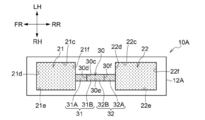
- FIG. 10A of the modification 1 shows a top view of the main body part 12A of the container 10A of the modification 1.
- FIG. 10 is a perspective view which shows a part of the nucleic acid extraction inspection apparatus 100 provided with a container 110.
- FIG. 1 is a perspective view showing a schematic configuration of the separation device 15.
- the separation device 15 shown in FIG. 1 is a device that separates the magnetic particles P from the liquid L1 containing the magnetic particles P (see FIG. 5).
- the separation device 15 includes a container 10 according to the present embodiment, and a magnetic field generation moving unit including a magnet M and a moving mechanism (not shown) for moving the magnet M.
- FIG. 2 is an exploded perspective view showing a schematic configuration of the container 10.
- FIG. 3 is a cross-sectional view showing a schematic configuration of the container 10.
- FIG. 4 is a plan view showing a schematic configuration of the main body 12 of the container 10.
- the container 10 shown in FIGS. 2, 3 and 4 has a first accommodating portion 21 for accommodating the first liquid L1 containing the magnetic particles P, and the magnetic particles (separated magnetic particles) P separated from the first liquid L1.
- a second accommodating portion 22 accommodating the second liquid L2 and a flow path 30 communicating the first accommodating portion 21 and the second accommodating portion 22 at the upper end positions of each other are provided.
- the flow path 30 is provided with a first staircase portion 31 having two steps from the inner bottom surface 21a of the first accommodating portion 21 on the side of the first accommodating portion 21.
- the flow path 30 also includes a second staircase portion 32 having two steps from the inner bottom surface 22a of the second accommodating portion 22 on the second accommodating portion 22 side.
- first staircase portion 31 and the second staircase portion 32 are a part of the flow path 30.
- the first staircase portion 31 is provided in the region adjacent to the first accommodating portion 21 of the flow path 30, and the second staircase portion 32 is provided in the region adjacent to the second accommodating portion 22 of the flow path 30. There are.
- the container 10 includes a main body 12 that constitutes the side walls and bottom surfaces of the first storage portion 21, the second storage portion 22, and the flow path 30, and the first storage portion 21, the second storage portion 22, and the second storage portion 22 of the main body 12. It is installed so as to cover the opening of the flow path 30, and includes a first accommodating portion 21, a second accommodating portion 22, and an upper surface member 14 constituting the upper surfaces 21b, 22b, and 30b of the flow path 30. Dispensing ports for dispensing liquid may be provided in the regions of the upper surface member 14 corresponding to the upper surfaces 21b and 22b of the first accommodating portion 21 and the second accommodating portion 22.
- the upper surface member 14 may not be provided with a dispensing port, and the first liquid L1 and the second liquid L2 may be added to the respective accommodating portions 21 and 22, respectively, and then the upper surface member 14 may be placed on the upper surface of the main body portion 12 and adhered. ..
- the flow path 30 is a flow path through which the magnetic particles P separated from the first liquid L1 pass.
- the upper surface 30b of the flow path 30 is flush with the upper surface 21b of the first accommodating portion 21 and the upper surface 22b of the second accommodating portion 22, and the flow path 30 is flush with the first accommodating portion 21 and the second accommodating portion 21. It communicates with the accommodating portion 22 at the upper end position.
- the arrangement of the flow paths 30 is not limited to this configuration.
- the flow path 30 may be provided at a position slightly lower than the upper end positions of the first accommodating portion 21 and the second accommodating portion 22.
- the flow path 30 has a width W1 narrower than the width W of the first accommodating portion 21 and the second accommodating portion 22.
- the width W1 of the flow path 30 may be the same as the width W of the first accommodating portion 21 and the second accommodating portion 22, but the width W1 narrower than the width of the first accommodating portion 21 and the second accommodating portion 22 is more. preferable.
- the width W1 of the flow path 30 is preferably 1/2 or less, more preferably 1/3 or less of the width W of the first accommodating portion 21.
- the first staircase portion 31 of the flow path 30 includes the first step 31A on the first accommodating portion 21 side and the second step 31B.
- the first staircase portion 31 is not limited to two steps, and may be three steps or four or more steps. However, from the viewpoint of avoiding complication of the structure, the first staircase portion preferably has two or three steps.
- the height h11 of the first stage 31A may be 25% or more and 80% or less of H1 when the height (depth) from the inner bottom surface 21a to the upper surface 21b of the first accommodating portion 21 is H1. It is more preferably 30% or more and 80% or less, and further preferably 50% or more and 80% or less.
- the height h12 of the second stage 31B is preferably 50% or more and 96% or less, preferably 60% or more and 96% or less, and 80% or more of the height H1 of the first accommodating portion 21. And it is more preferably 96% or less.
- the difference between the height h12 of the second step 31B and the height h11 of the first step 31A is preferably 20% or more of the height h11 of the first step 31A.
- the second staircase portion 32 of the flow path 30 includes the first step 32A on the second accommodating portion 22 side and the second step 32B.
- the second staircase portion 32 is not limited to two steps, and may be three steps or four or more steps. However, from the viewpoint of avoiding complication of the structure, the second staircase portion preferably has two or three steps.
- the height h21 of the first stage 32A is preferably 25% or more of H2, preferably 30%, when the height (depth) from the inner bottom surface 22a to the upper surface 22b of the second accommodating portion 22 is H2.
- the above is more preferable, and 50% or more is further preferable.
- the height h22 of the second stage 32B is preferably 50% or more, preferably 60% or more, and more preferably 80% or more of the height H2 of the second accommodating portion 22.
- the difference between the height h22 of the second stage 32B and the height h21 of the first stage 32A is preferably 20% or more of the height h21 of the first stage 32A from the viewpoint of liquid sealing property.
- the height H1 of the first accommodating portion 21 and the height H2 of the second accommodating portion 22 are the same, and the first staircase portion 31 and the second staircase portion 32 of the flow path 30 have the flow of the flow path 30. It has a shape symmetrical with respect to the center of the direction. Therefore, the height h11 of the first step 31A of the first staircase portion 31 and the height h21 of the first step 32A of the second staircase portion 32 are the same, and the second step 31B and the second step 31B of the first staircase portion 31 are the same.
- the second step 32B of the two stairs portion 32 is a common step.
- the heights of the first accommodating portion 21 and the second accommodating portion 22 do not have to be the same, and the heights of the first steps of the first staircase portion 31 and the second staircase portion 32 do not have to be the same. Further, at least the first staircase portion 31 may have two or more steps, and the second staircase portion 32 may have only one step.
- any known resin molded plastic material can be used without particular limitation.
- acrylic resins such as polymethyl methacrylate resin (PMMA), polycarbonate resins, polyolefin resins such as polyethylene (PE) and polypropylene (PP), cycloolefin resins such as cycloolefin polymers (COP) and cyclic olefin copolymers (COC).
- Silicone resin fluororesin, polystyrene resin, polyvinyl chloride resin, phenol resin, urethane resin, polyester resin, epoxy resin, cellulose resin and the like.
- the size (capacity) of the first accommodating portion 21 and the second accommodating portion 22 is, for example, about 1 ⁇ L (microliter) to several hundred ⁇ L.
- the magnet M is, for example, a permanent magnet, but may be an electromagnet. As shown in FIG. 1, the magnet M is freely moved between positions A0, A1, A2 and A3 on the upper surface member 14 of the container 10. Positions A0 and A3 are positions where no magnetic force acts on the magnetic particles P housed inside the container 10 even if the magnet M is arranged.
- the position A1 is a position on the first accommodating portion 21, and is a position where a magnetic force is applied to the magnetic particles in the first accommodating portion 21 when the magnet M is arranged.
- the position A2 is a position on the second accommodating portion 22, and is a position where a magnetic force is applied to the magnetic particles in the second accommodating portion 22 when the magnet M is arranged.
- the magnetic particles P housed in the first accommodating portion 21 are collected by the magnetic force of the magnet M, and are attracted to the position corresponding to the magnet M across the upper surface member 14. It becomes a state.
- the magnetic particles accommodated in the second accommodating portion 22 are attracted to and gathered at the position corresponding to the magnet M across the upper surface member 14.
- a desired treatment solution can be appropriately selected for each of the first liquid L1 and the second liquid L2.
- the treatment solution is a solution for subjecting a sample to some kind of treatment.
- the second liquid L2 is, for example, a treatment solution having characteristics different from those of the first liquid L1 and is a treatment solution used in a step after the treatment with the first liquid L1.
- the first liquid L1 for example, a treatment solution containing an adsorbent that exhibits an adsorbing action on the magnetic particles P is used.
- a sample liquid containing a sample as an adsorbent is used.
- a sample liquid containing nucleic acid released from cells as a sample is used.
- Examples of the second liquid L2 include a cleaning liquid for removing a substance non-specifically adsorbed on the magnetic particles P, a DNA (deoxyribonucleic acid) amplification liquid, a detection pretreatment liquid, and the like.
- Magnetic particles P are particles that are attracted by magnetic force. Further, the magnetic particles P are magnetic particles that have been treated so that a specific sample such as DNA is adsorbed. Specifically, as the magnetic particles P, it is possible to use JSR Corporation's model number: Magnosphere MX100 / Carboxyl, model number: Magnosphere MS160 / Tosyl, Corefront's sicastar, Sanyo Kasei's Magrapid, etc. is there.
- the magnetic particles P magnetic particles having a particle size in the range of 0.01 ⁇ m or more and 100 ⁇ m or less are used.
- magnetic particles having a particle size of about 1 ⁇ m to 10 ⁇ m are used.
- the magnetic particles P may be provided in advance in the first accommodating portion 21 of the container 10, or may be injected into the first accommodating portion 21 together with the first liquid L1.
- the liquid L1 may contain a surfactant for extracting nucleic acid such as DNA from the sample and adsorbing the nucleic acid on the surface of the magnetic particles P.
- a surfactant for example, sodium dodecyl sulfate, polyoxyethylene sorbitan monolaurate (Tween 20), Triton X-100, or the like can be used. These surfactants may be used alone or in combination of two or more. Chaotropic substances such as guanidine hydrochloride may be included to promote nucleic acid extraction from the sample and surface adsorption to the magnetic particles P.
- a nucleic acid extracted from a sample using a column may be contained. Further, it may contain a surfactant for suppressing the aggregation of the magnetic particles P.
- FIG. 5 is a process diagram of the separation method.
- the first liquid L1 containing the magnetic particles P is stored in the first storage portion 21 of the container 10. Further, the second liquid L2 is stored in the second storage unit 22 (see ST0).
- the magnet M is set at the position A1 on the first accommodating portion 21 of the container 10.
- the magnetic particles P accommodated in the first accommodating portion 21 are attracted to the magnet M, and are gathered at a position corresponding to the magnet M on the upper surface 21b to be in a state of being aggregated (see ST1).
- the magnetic particles P move along the upper surface 21b of the first accommodating portion along with the movement of the magnet M, and are separated from the first liquid L1. It enters the flow path 30 and moves to a position corresponding to the magnet M on the upper surface 30b of the flow path (see ST2).
- the magnetic particles P move along with the movement of the magnet M and enter the second accommodating portion 22. Mix in liquid L2 (see ST3). However, since the magnet M is at the position A2, the magnetic particles P are in a state of being aggregated at a position corresponding to the magnet M on the upper surface 22b of the second accommodating portion.
- the separator 15 can be used in nucleic acid extraction tests, including the treatment of the polymerase chain reaction (PCR). For example, when nucleic acids such as RNA (ribonucleic acid) and DNA released from cells are adsorbed on magnetic particles and the magnetic particles on which the nucleic acids are adsorbed are separated from the mixed solution in which the nucleic acids are mixed, the separation device 15 is used. Can be used.
- PCR polymerase chain reaction
- the flow path 30 of the container 10 includes the first staircase portion 31 including two or more steps on the first accommodating portion 21 side, as compared with the case where there is only one staircase. Therefore, since the barrier of entry of the first liquid L1 contained in the first accommodating portion 21 into the flow path 30 becomes two or more stages, it is effective to flow into the second accommodating portion 22 through the flow path 30. Can be suppressed. When the magnetic particles P in the first liquid L1 housed in the first accommodating portion 21 are moved to the second accommodating portion 22 via the flow path 30, the first staircase portion 31 is provided.
- the second liquid L2 which is the processing solution in the subsequent process is combined with the first liquid L1 which is the processing solution in the previous process. If mixed in, the inspection accuracy may decrease.
- this container 10 it is possible to suppress the mixing of the first liquid L1 into the second liquid L2, so that the inspection can be performed with high accuracy.
- the second liquid L2 accommodated in the second accommodating portion 22 is the first. Since the movement to the accommodating portion 21 side can be suppressed, the mixing of the first liquid L1 and the second liquid L2 can be effectively suppressed.
- the contact angle (water contact angle) of the inner surface of the flow path 30 with water is preferably 90 ° or more and 180% or less. , 120 ° or more and 180% or less are more preferable, and 150 ° or more and 180% or less are further preferable.
- the water contact angle of the inner surface of the flow path 30 can be set to 90 ° or more.
- the water contact angle of the inner surfaces of the first accommodating portion 21 and the second accommodating portion 22 may be the same as the water contact angle of the inner surface of the flow path 30.
- it is preferable that the angle is smaller than the water contact angle on the inner surface of the flow path 30.
- ° represents "degree" which is a unit of angle.
- the water contact angle is the contact angle of pure water. Specifically, using a fully automatic contact angle meter (model number: DM-701, Kyowa Interface Science Co., Ltd.), 1 ⁇ L of pure water was dropped on the inner surface of the flow path and the accommodating portion under the condition of an atmospheric temperature of 25 ° C. After that, the contact angle is measured by the ⁇ / 2 method, and the value obtained by measuring 5 times is used as the arithmetic mean value.
- FIG. 6 is a cross-sectional view of the container 10A of the modified example 1
- FIG. 7 is a plan view of the main body 12A of the container 10A of the modified example 1.
- the inner surface of the container 10 of the above embodiment is surface-treated so that the water contact angle of the inner surface of the first accommodating portion 21 is smaller than the water contact angle of the inner surface of the flow path 30. .. Further, the surface treatment of the inner surface is performed so that the water contact angle of the inner surface of the second accommodating portion 22 is smaller than the water contact angle of the inner surface of the flow path 30.
- the first accommodating portion 21 is composed of a bottom surface 21a, an upper surface 21b, an LH side wall surface 21c, an FR side wall surface 21d, an RH side wall surface 21e and an RR side wall surface 21f, and these surfaces 21a to 21f are the first accommodating portions 21.
- the second accommodating portion 22 is composed of a bottom surface 22a, an upper surface 22b, an LH side wall surface 22c, an FR side wall surface 22d, an RH side wall surface 22e and an RR side wall surface 22f, and these surfaces 22a to 22f are the second accommodating portions 22. Is the inside of.
- the flow path 30 is composed of a bottom surface 30a, an upper surface 30b, an LH side wall surface 30c, an FR side wall surface 30d, an RH side wall surface 30e and an RR side wall surface 30f, and these surfaces 30a to 30f are inner surfaces of the flow path 30. Is.
- FIGS. 6 and 7 the inner surface regions of the first accommodating portion 21 and the second accommodating portion 22 that have been subjected to the hydrophilization treatment are indicated by dots. Further, the area on the inner surface of the flow path 30 that has been subjected to the hydrophobizing treatment is shown by an oblique line.
- the first liquid L1 accommodating in the first accommodating portion 21 since the water contact angle on the inner surface of the first accommodating portion 21 is smaller than the water contact angle on the inner surface of the flow path 30, the first liquid L1 accommodating in the first accommodating portion 21 The entry into the flow path 30 can be further suppressed. A higher effect can be obtained in addition to the effect of suppressing the entry of the first liquid L1 into the flow path 30 by the first staircase portion 31.
- the second liquid L2 accommodated in the second accommodating portion 22 can enter the flow path 30. It can be further suppressed. A higher effect can be obtained in addition to the effect of suppressing the entry of the second liquid L2 into the flow path 30 by the second staircase portion 32.
- the surface treatment such as hydrophilization treatment or hydrophobic treatment is preferably formed on the entire inner surface, but a part of the inner surface may not be surface-treated. It is preferable that at least a region adjacent to the boundary between the first accommodating portion 21 and the flow path 30 and a region adjacent to the boundary between the second accommodating portion 21 and the flow path 30 are surface-treated.
- hydrophilic treatment examples include surface modification treatments such as corona treatment, plasma treatment, and ozone treatment, coating treatment of a hydrophilic coating agent, and bonding of a hydrophilic film.
- hydrophobic treatment examples include a treatment of applying a hydrophobic coating agent, a silane coupling treatment, and a bonding of a water-repellent film.
- the water contact angle on the inner surface of the flow path 30 is preferably 90 ° or more, more preferably 120 ° or more, and particularly preferably 150 ° or more.
- the water contact angle on the inner surface of the first accommodating portion 21 may be smaller than the water contact angle on the inner surface of the flow path 30.
- the water contact angle of the first accommodating portion 21 is preferably 0 ° or more and 60 ° or less, and further preferably 0 ° or more and 30 ° or less.
- the water contact angle on the inner surface of the flow path 30 may be larger than the water contact angle on the inner surface of the first accommodating portion 21, but the water contact angle on the inner surface of the flow path 30 is preferably 80 ° or more, and 90 ° or more. Is more preferable, and 120 ° or more is further preferable.
- the water contact angle of the second accommodating portion 22 is preferably 0 ° or more and 60 ° or less, and further preferably 0 ° or more and 30 ° or less.
- the difference between the water contact angle on the inner surface of the flow path 30 and the water contact angle on the inner surface of the first accommodating portion 21 is preferably 10 ° or more, more preferably 20 ° or more, further preferably 40 ° or more, and 60 ° or more. Is particularly preferable.
- the difference between the water contact angle on the inner surface of the flow path 30 and the water contact angle on the inner surface of the second accommodating portion 22 is preferably 10 ° or more, more preferably 20 ° or more, still more preferably 40 ° or more. , 60 ° or more is particularly preferable.
- the first accommodating portion 21, the second accommodating portion 22, and the flow path 30 are integrally formed, the first accommodating portion 21, the second accommodating portion 22, and the flow path are not subjected to surface treatment.
- the water contact angles on the inner surface of 30 are the same.
- the flow path 30 is made hydrophobic so that the water contact angle on the inner surface of the flow path 30 is larger than the water contact angle on the inner surfaces of the first accommodating portion 21 and the second accommodating portion 22.
- the first accommodating portion 21 and the second accommodating portion 22 are treated to be hydrophilized, but the inner surface of the flow path 30 is hydrophobized to be in contact with water more than the inner surface without surface treatment.
- the inner surfaces of the first accommodating portion 21 and the second accommodating portion 22 need not be surface-treated.
- the inner surfaces of the first accommodating portion 21 and the second accommodating portion 22 are hydrophilized to make the water contact angle smaller than the inner surface not surface-treated, the inner surface of the flow path 30 is surface-treated. It does not have to be.
- the angles of the steps 31A and 31B of the first staircase 31 and the angles of the steps 32A and 32B of the second staircase 32 are right angles in the cross-sectional view of FIG.
- the angle ⁇ of the angle in the cross-sectional view of the step 31A may be an acute angle as in the container 10B of the modified example shown.
- the angle of the angle of the step is defined by the angle in the cross section parallel to the extending direction of the flow path (FR-RR) and parallel to the direction perpendicular to the flow path (UP-DW).
- the corner of the step 31A of the first staircase portion 31 is an acute angle, but the corners of all the steps 31A, 31B, 32A, 32B included in the flow path 30 are acute angles. May be good. If at least one angle of the steps 31A and 31B of the first staircase portion 31 is an acute angle, the effect of suppressing the entry of the first liquid L1 from the first accommodating portion 21 into the flow path 30 is enhanced. Further, if at least one angle of the steps 32A and 32B of the second staircase portion 32 is an acute angle, the effect of suppressing the entry of the second liquid L2 from the second accommodating portion 22 into the flow path 30 is enhanced.
- FIG. 9 is a perspective view showing a part of the nucleic acid extraction test apparatus 100 provided with the container 110 according to the second embodiment of the technique of the present disclosure.
- FIG. 10 shows a cross-sectional view of the container 110 and a part of the nucleic acid extraction test apparatus 100.
- the nucleic acid extraction test apparatus 100 includes the container 110 according to the second embodiment and the syringe 161 for adding various liquids 151 to 154 to the respective storage portions 121 to 124 of the container 110.
- a magnetic field generation moving unit including a magnet M and a moving mechanism (not shown) for moving the magnet M, and a temperature control unit 170 are provided.
- the container 110 has four accommodating portions 121 to 124 capable of accommodating liquids, a chromatographic carrier accommodating portion 125 in which a chromatographic carrier 128 is installed, four flow paths 130, 135, 139, 145, and a valve 140. And have.
- the container 110 includes a main body 112 that constitutes the side wall surface and bottom surface of each of the accommodating portions 121 to 125 and the flow paths 130, 135, 139, and 145, and the respective accommodating portions 121 to 125 and the flow paths 130 and 135 of the main body portion 112. It is installed so as to cover the openings of 139 and 145, and includes accommodating portions 121 to 125 and an upper surface member 114 constituting the upper surfaces of the flow paths 130, 135, 139 and 145.
- the upper surface member 114 is provided with injection ports 114a to 114d for injecting the liquid contained in each of the accommodating portions 121 to 124.
- the tips of syringes 161 to 164 are inserted into the injection ports 114a to 114d, respectively, and various liquids can be injected into the corresponding storage portions 121 to 124, respectively.
- the accommodating portion 121 is a magnetic particle magnetizing chamber (hereinafter, referred to as a magnetic accumulating chamber 121) for accommodating a sample liquid 151 containing magnetic particles P on which nucleic acids are adsorbed.
- the accommodating portion 122 is a cleaning chamber (hereinafter, referred to as a cleaning chamber 122) that stores the cleaning liquid 152 and cleans the substance non-specifically adsorbed on the magnetic particles P.
- the storage unit 123 is a PCR chamber (hereinafter referred to as PCR chamber 123) that stores the PCR solution 153.
- the storage unit 124 is an inspection chamber (hereinafter, referred to as an inspection chamber 124) for mixing the amplified nucleic acid and the developing solution 154.
- the developing liquid 154 is a form of an inspection pretreatment liquid.
- the chromatographic carrier accommodating unit 125 accommodates the chromatograph carrier 128.
- a developing solution 154 containing the amplified nucleic acid is developed.
- the chromatograph carrier 128 is a nucleic acid chromatograph carrier, and indicates whether or not a target nucleic acid is present in the developing solution 154.
- the flow path 130 communicates the magnetic collection chamber 121 and the cleaning chamber 122 at the upper end positions of each other.
- the magnetic collecting chamber 121, the cleaning chamber 122, and the flow path 130 correspond to the first accommodating portion, the second accommodating portion, and the flow path in the technique of the present disclosure, respectively.
- the relationship between the magnetic collecting chamber 121, the cleaning chamber 122, and the flow path 130 is the same as the relationship between the first accommodating portion 21, the second accommodating portion 22, and the flow path 30 in the container 10 of the first embodiment. That is, the flow path 130 is provided with a first step portion on the magnetic collection chamber 121 side and a second step portion on the cleaning chamber 122 side, so that the sample liquid 151 contained in the magnetic collection chamber 121 enters the flow path 130. It is configured to suppress and suppress the mixing of the sample liquid 151 into the cleaning liquid 152 housed in the cleaning chamber 122.
- the flow path 135 communicates the cleaning chamber 122 and the PCR chamber 123 at the upper end positions of each other.
- the relationship between the wash chamber 122, the PCR chamber 123 and the flow path 135 also corresponds to the first containment portion, the second containment portion and the flow path in the technique of the present disclosure.
- the relationship between the washing chamber 122, the PCR chamber 123, and the flow path 135 is the same as the relationship between the first storage unit 21, the second storage unit 22, and the flow path 30 in the container 10 of the first embodiment. That is, the flow path 135 is provided with a first step portion on the cleaning chamber 122 side and a second step portion on the PCR chamber 123 side, and prevents the cleaning liquid 152 contained in the cleaning chamber 122 from entering the flow path 135. However, it is configured so that the washing liquid 152 is suppressed from being mixed into the PCR solution 153 contained in the PCR chamber 123.
- the flow path 139 communicates the PCR chamber 123 and the inspection chamber 124 at the upper end positions of each other.
- the flow path 139 is provided with a valve 140, and by opening and closing the valve 140, the inflow of the PCR solution into the inspection chamber 124 in the PCR chamber 123 is controlled.
- the valve 140 includes a rotatable flow path portion installed in the flow path 139. The valve 140 is "open" when the flow path portion is rotated in the flow path 129 and the flow path portion is rotated in a direction parallel to the flow path 139, allowing the flow of fluid, and the rotating flow path. Is rotated in a direction orthogonal to the flow path 139, it becomes “closed” and blocks the flow of fluid.
- the flow path 145 communicates the inspection chamber 124 and the chromatographic carrier accommodating portion 125 at the lower end positions of each other.
- the magnet M is the same as that described in the separation device 15.
- the moving mechanism for moving the magnet M passes the magnet M from the position on the magnetizing chamber 121 on the flow path 130, to the position on the cleaning chamber 122, and further on the flow path 135, and on the PCR chamber 123. Move to position. Further, the moving mechanism moves the magnet M from above the PCR chamber 123 to a position where the magnetic force does not reach the inside of the PCR chamber 123.
- the temperature control unit 170 controls the temperature of the PCR solution in the PCR chamber 123.
- the temperature control unit 170 includes a heating means such as a heater for heating the solution and a cooling means such as a Peltier element for cooling the solution.
- the temperature control unit 170 raises or lowers the temperature of the solution so that the temperature becomes appropriate for each step of the heat denaturation step, the annealing step, and the extension step in PCR.
- RNA is adsorbed on the magnetic particle P.
- the sample containing RNA is not particularly limited as long as it contains RNA, such as a biological sample or a virus. If necessary, impurities may be removed by a filter or the like.
- the sample solution 151 containing the magnetic particles P on which RNA is adsorbed, which is obtained in the pretreatment, is injected into the accommodating portion 121 by the syringe 161.
- the magnet M is set on the upper surface of the accommodating portion 121.
- the magnetic particles P accommodated in the accommodating portion 121 are attracted to the magnet M and gather at a position corresponding to the magnet M on the upper surface to be in a state of aggregation. (See FIG. 10).
- the adsorption step and the magnetic collection step may be performed in chronological order.
- the magnetic particles P are separated from the sample liquid 151 and moved to the cleaning chamber 122.
- the movement of the magnetic particles P is the same as that described in the above separation method. Since the flow path 130 includes the first staircase portion having two or more steps, the entry of the sample liquid 151 in the accommodating portion 121 into the flow path 130 when the magnetic particles P move is suppressed, and the magnetic particles P are prevented from entering the flow path 130. It can be easily separated from the sample liquid 151 and moved to the storage unit 122.
- the magnetic particles P on which RNA is adsorbed are washed with the washing liquid 152 contained in the washing chamber 122.
- the cleaning chamber 122 may be pre-filled with the cleaning liquid 152, or the cleaning liquid 152 may be injected after the magnetic particles P have moved. Cleaning can be promoted by moving the magnet M to a position where the magnetic force does not affect the cleaning chamber 122 and dispersing the magnetic particles P in the cleaning liquid 152. By washing, substances other than RNA that are non-specifically bound to the magnetic particles P are removed.
- the cleaning liquid 152 water, a buffer solution, an organic solvent such as ethanol or isopropyl alcohol, or the like can be used.
- the salt is not particularly limited, but salts such as tris and phosphoric acid are preferably used. Further, in order to suppress the elution of RNA in the washing step, a surfactant such as sodium dodecyl sulfate or Triton X-100 may be contained.
- the magnetic particles P are collected again at the positions corresponding to the magnets M on the upper surface, and the magnets M are moved along the flow path 135 to remove the magnetic particles P into the cleaning liquid 152. Separated from and moved to PCR chamber 123.
- the movement of the magnetic particles P is the same as that described in the above separation method.
- the flow path 135 includes the first step portion having two or more steps, the entry of the cleaning liquid 152 into the flow path 135 in the cleaning chamber 122 during the movement of the magnetic particles P is suppressed, and the magnetic particles are prevented from entering the flow path 135. P can be easily separated from the wash solution 152 and transferred to the PCR chamber 123.
- RNA adsorbed on the magnetic particles P is eluted in the PCR solution 153, and DNA amplification by PCR is performed.
- the PCR solution 153 contains, for example, reverse transcriptase, dNTP mixed with four kinds of deoxyribonucleotide triphosphates, and a primer for reverse transcriptase.
- Transcriptase is an enzyme that synthesizes cDNA (complementary deoxyribonucleic acid) using the base sequence of RNA as a template.
- CDNA is synthesized from the extracted RNA, and the cDNA is amplified by PCR.
- valve 140 is opened to allow the solution containing the amplified cDNA to flow into the detection chamber 124.
- the solution containing the cDNA is mixed with the developing solution. Then, the mixed liquid passes through the flow path 145 and is developed by a nucleic acid chromatograph carrier (chromatography carrier 128) arranged in the chromatograph carrier accommodating portion 125. If the RNA to be tested is contained, a positive result is obtained, and if it is not contained, a negative result is obtained.
- a nucleic acid chromatograph carrier chromatography carrier 1228
- the nucleic acid extraction test is performed.
- the detection method is not limited to the nucleic acid chromatography method, but is a fluorescence detection method (intercalator method, probe method, etc.), and light scattering using gold nanoparticles.
- a known method such as a method or a sequencing method can be used.
- the container need not be equipped with a chromatographic carrier 138 and its accommodating portion 125.
- the inspection device may be provided with a detection unit suitable for various detection methods such as a fluorescence detection unit for detecting fluorescence from the detection chamber 124.
- the nucleic acid chromatography method is preferable because it does not require an expensive detection system and detection equipment and is easy to operate in analysis.
- the container 110 By using the container 110, it is possible to suppress the mixing of the liquid between the magnetic collecting chamber 121 and the washing chamber 122, and it is possible to suppress the mixing of the liquid between the washing chamber 122 and the PCR chamber 123. Therefore, it is possible to prevent impurities in the solution used in the previous step from being mixed in the solution in the next step, which leads to improvement in determination accuracy.
- FIG. 11 shows a schematic configuration of the inspection kit 200 according to the embodiment.
- the test kit 200 includes the container 110, magnetic particles P, and various treatment solutions such as a cleaning solution 152, a PCR solution 153, and a developing solution 154.
- the container 110 can be provided as a test kit 200 together with the magnetic particles P, the cleaning liquid 152, the PCR reaction liquid 153, and the developing liquid 154.
- the test kit 200 may further contain another treatment solution such as a nucleic acid eluate.
- the magnetic particles P may be preset in the accommodating portion 121 of the container 110, or may be prepared separately.
- Examples and comparative examples of containers provided with two accommodating portions and a flow path connecting the two accommodating portions were prepared and evaluated.
- Example 1 As Example 1, a container having the same shape as the container shown in FIGS. 2 to 4 was produced.
- FIG. 12 shows a plan view of the container main body of the first embodiment and a cross-sectional view of the container.
- the container 210 of the first embodiment has a shape in which the first accommodating portion 221 and the second accommodating portion 222 are connected by one flow path 230.
- the flow path 230 includes a first staircase portion 231 on the first accommodating portion 221 side and a second staircase portion 232 on the second accommodating portion 222 side.
- the first staircase portion 231 and the second staircase portion 232 have symmetrical shapes. That is, the height of each step of the second staircase portion 232 is the same as the height of each step of the first staircase portion 231.
- the height h1 from the bottom surface of the first accommodating portion 221 of the first step 231A of the first staircase portion 231 is 0.25 mm
- the height h2 from the bottom surface of the first accommodating portion 221 of the second step 231B is 0.5 mm. did.
- the width of the flow path 130 was set to 1 mm.
- the main body 212 of the container 210 includes a main main body 212A constituting the side wall surfaces of the first accommodating portion 221 and the second accommodating portion 222 and the flow path 230, and the first accommodating portion 221 and the second accommodating portion 222 and the flow path 230. It was composed of a bottom member 212B constituting the bottom surface of the above.
- PC Polycarbonate
- the main body 212A was injection molded using Iupiron EB-3001R manufactured by Mitsubishi Engineering Plastics Co., Ltd. Technoroy C000 (thickness 100 ⁇ m) manufactured by Sumika Acrylic Sales Co., Ltd. was used for the bottom member 212B and the top member 214.
- the top surface member 214 and the bottom surface member 212B were roller-attached to the upper surface and the bottom surface of the main body portion 212A using the adhesive # 9996 manufactured by 3M Japan Ltd. to obtain the container 210 of Example 1.
- Example 2 A container of Example 2 was obtained in the same manner as in Example 1 except that the height h2 from the bottom surface of the first accommodating portion 221 of the second step 231B of the first staircase portion 231 was set to 0.65 mm.
- Example 3 A container of Example 3 was obtained in the same manner as in Example 1 except that the height h2 from the bottom surface of the first accommodating portion 221 of the second step 231B of the first staircase portion 231 was set to 0.8 mm.
- Example 4 The height h1 from the bottom surface of the first accommodating portion 221 of the first step 231A of the first staircase portion 231 is 0.5 mm, and the height h2 from the bottom surface of the first accommodating portion 221 of the second step 231B is 0.8 mm.
- a container of Example 4 was obtained in the same manner as in Example 1.
- Example 5 is the same as in Example 1 except that the first staircase portion 231 is provided with a third step and the height h3 from the bottom surface of the first accommodating portion 221 of the third step is set to 0.8 mm. Obtained a container.
- Example 6 A container of Example 6 was obtained in the same manner as in Example 1 except that the inner surface of the flow path 230 was hydrophobized.
- As the hydrophobizing treatment of this example fluorotechnology Co., Ltd. (FS-1610) was applied with a brush and then dried at 70 ° C. for 1 minute (referred to as "fluorine" in the table below). That is, the water contact angle on the inner surface of the flow path 230 was made larger than the water contact angle on the inner surfaces of the first accommodating portion 221 and the second accommodating portion 222.
- Example 7 A container of Example 7 was obtained in the same manner as in Example 1 except that the inner surface of the flow path 230 was hydrophobized.
- the hydrophobizing treatment of this example was as follows. A resin composition containing hydrophobic colloidal silica was applied to the inner surface of the flow path 230 with a brush, and then dried at 100 ° C. for 1 minute. Next, the resin composition was cured by irradiating the light of a metal halide lamp (MAL625NAL manufactured by GS Yuasa Co., Ltd.) with an exposure amount of 300 mJ / cm 2 in a low oxygen atmosphere having an oxygen concentration of 1000 ppm or less, and the flow path 230.
- a metal halide lamp MAL625NAL manufactured by GS Yuasa Co., Ltd.
- a water-repellent resin layer was formed on the inner surface of the (referred to as "hydrophobic silica" in the table below). That is, the water contact angle on the inner surface of the flow path 230 was made larger than the water contact angle on the inner surfaces of the first accommodating portion 221 and the second accommodating portion 222.
- the resin composition containing hydrophobic colloidal silica was obtained by mixing the following components.
- -Resin composition- 1-methoxy-2-propanol manufactured by Fujifilm Wako Pure Chemical Industries, Ltd.
- A-DPH Shin Nakamura Chemical Industry Co., Ltd., 1-methoxy-2-propanol 10% diluted solution
- Fluorine-based surfactant Megafuck F-780F DIC, MEK 2% diluted solution
- Hydrophobic silica dispersion 2.61 g IRGACURE127 (manufactured by BASF Japan Ltd., diluted 1-methoxy-2-propanol by 2%): 0.21 g
- the hydrophobic silica dispersion contained in the above resin composition was prepared by the following procedure.
- a hydrophobic silica dispersion was obtained by mixing trimethylsilyl group-modified silica and 1-methoxy-2-propanol and treating with an ultrasonic homogenizer Sonifier450 manufactured by Emerson Japan, Ltd. for 10 minutes while cooling with ice water.
- hydrophobic silica dispersion Trimethylsilyl group-modified silica (AEROSIL RX200 (fumed silica manufactured by Aerosil Japan)): 1 g 1-methoxy-2-propanol (manufactured by Fujifilm Wako Pure Chemical Industries, Ltd.): 19 g
- Example 8 A container of Example 8 was obtained in the same manner as in Example 1 except that the inner surfaces of the accommodating portions 221 and 222 were hydrophilized.
- the inner surfaces of the accommodating portions 221 and 222 were subjected to corona treatment under the condition of 2000 J / m2. That is, by reducing the water contact angle of the accommodating portions 221, 222, as a result, the water contact angle of the inner surface of the flow path 230 is made larger than the water contact angle of the inner surface of the accommodating portions 221, 222.
- Example 9 A container of Example 9 was obtained in the same manner as in Example 1 except that the inner surfaces of the accommodating portions 221 and 222 were hydrophilized.
- the hydrophilic film was installed only on the upper surface and the inner bottom surface of the accommodating portions 221 and 222.
- a hydrophilic treated film # 9984 manufactured by 3M Japan Ltd. was used as the hydrophilic film. That is, by reducing the water contact angle of the accommodating portions 221, 222, as a result, the water contact angle of the inner surface of the flow path 230 is made larger than the water contact angle of the inner surface of the accommodating portions 221, 222.
- Example 10 A container of Example 10 was obtained in the same manner as in Example 1 except that polypropylene (PP) was used as the material of the container 210. Specifically, the main body 212A constituting the accommodating portion and the side wall surface of the flow path is injection-molded using WINTEC WMG03UX manufactured by Japan Polypropylene Corporation, and the bottom member 212B and the top member 214 are trefans manufactured by Toray Industries, Inc. BO60-2500 (thickness 60 ⁇ m) was used.
- PP polypropylene
- Example 11 A container of Example 11 was obtained in the same manner as in Example 1 except that COP was used as the material of the container 210. Specifically, the main body portion 212A constituting the accommodating portion and the side wall surface of the flow path is injection-molded using ARTON F4520 manufactured by JSR Corporation, and the bottom surface member 212B and the top surface member 214 are formed with ARTON R5000 manufactured by JSR Corporation. A film having a thickness of 50 ⁇ m obtained by forming a film was used.
- Example 12 A container of Example 12 was obtained in the same manner as in Example 1 except that the height h2 from the bottom surface of the first accommodating portion 221 of the second step 231B of the first staircase portion 231 was set to 0.3 mm.
- Example 13 A container of Example 13 was obtained in the same manner as in Example 1 except that the inner surface of the flow path 230 was hydrophilized.
- the hydrophilic treatment a corona treatment was performed. That is, the water contact angle of the flow path 230 was made smaller than the water contact angle of the accommodating portions 221, 222.
- Comparative Example 1 A container of Comparative Example 1 was obtained in the same manner as in Example 1 except that the first staircase portion 231 of the flow path 230 had only one step.
- the height of the inner bottom surface of the flow path from the inner bottom surface of the accommodating portion corresponds to the height h1 of one step.
- h1 is 0.1 mm.
- Comparative Example 2 A container of Comparative Example 2 was obtained in the same manner as in Comparative Example 1 except that h1 was set to 0.5 mm.
- D or more is preferable, C or more is more preferable, and B or more is further preferable.
- Table 1 summarizes the container configuration, measurement, and evaluation results of each example.
- the height of the second step is different, and the higher the height of the second step, the higher the liquid sealing property. It is preferable that the height of the second stage is 50% or more of the height of the container as compared with the case where the height of the second stage is 30% of the height of the container as in Example 12. Conceivable.
- Example 4 the height of the first step was increased as compared with Example 3 to 50% of the height of the accommodating portion, so that a very preferable liquid sealing property was obtained.
- Example 5 the liquid sealing property was improved as compared with Example 1 having two steps.
- the container has the same shape as that of the first embodiment as in Examples 6 to 9, the water contact angle of the inner surface of the flow path is made larger than the water contact angle of the inner surface of the accommodating portion, so that the liquid sealing property can be obtained. Is clearly higher. Particularly preferable liquid sealing properties were obtained in Examples 7 and 9 in which the difference in water contact angle between the flow path and the accommodating portion exceeds 50 °.
- the material of the container is different from that of Example 1, and the water contact angle on the inner surface of the container is larger than that of Example 1.
- the water contact angle between the inner surface of the accommodating portion and the inner surface of the flow path is the same, but it is considered that the larger the water contact angle on the inner surface of the container, the higher the liquid sealing property.
Abstract
Description
第1液体から分離された分離磁性粒子および第2液体を収容する第2収容部と、
第1収容部と第2収容部とを互いに連通する流路であって、分離磁性粒子を通過させる流路とを備え、
流路が、第1収容部の内底面から2以上の段を含む第1階段部を第1収容部側に有する容器である。 The container of the present disclosure includes a first container for accommodating a first liquid containing magnetic particles, and a first container.
A second accommodating portion for accommodating the separated magnetic particles separated from the first liquid and the second liquid,
It is a flow path that communicates the first accommodating portion and the second accommodating portion with each other, and includes a flow path through which the separated magnetic particles pass.
The flow path is a container having a first staircase portion including two or more steps from the inner bottom surface of the first accommodating portion on the first accommodating portion side.
最初に、第1実施形態に係る容器10を用いた分離装置15について説明する。図1は、分離装置15の概略構成を示す斜視図である。 (Separator 15)
First, the
本実施形態に係る容器10について説明する。図2は、容器10の概略構成を示す分解斜視図である。図3は、容器10の概略構成を示す断面図である。図4は、容器10の本体部12の概略構成を示す平面図である。 (Container 10)
The
第1収容部21および第2収容部22の大きさ(容量)は、例えば、1μL(マイクロリットル)~数100μL程度である。 As the material of the
The size (capacity) of the first
磁石Mは、例えば、永久磁石であるが、電磁石であってもよい。図1に示すように、磁石Mは、容器10の上面部材14上で位置A0、A1、A2およびA3間で自在に移動される。位置A0および位置A3は、磁石Mが配置されていても容器10内部に収容されている磁性粒子Pに対して磁力が作用しない位置である。位置A1は第1収容部21上の位置であり、磁石Mが配置された場合に第1収容部21内の磁性粒子に磁力を作用させる位置である。位置A2は第2収容部22上の位置であり、磁石Mが配置された場合第2収容部22内の磁性粒子に磁力を作用させる位置である。位置A1に磁石Mが位置する場合、第1収容部21に収容されている磁性粒子Pは磁石Mの磁力によって集められ、上面部材14を隔てて磁石Mに対応する位置に引き寄せられた集まった状態となる。同様に、位置A2に磁石Mが位置する場合、第2収容部22に収容されている磁性粒子は、上面部材14を隔てて磁石Mに対応する位置に引き寄せられ集まった状態となる。 (Magnet M)
The magnet M is, for example, a permanent magnet, but may be an electromagnet. As shown in FIG. 1, the magnet M is freely moved between positions A0, A1, A2 and A3 on the
第1液体L1と第2液体L2とは、それぞれ所望の処理溶液を適宜選択することができる。処理溶液とは、検体に対して何らかの処理を施すための溶液である。第2液体L2は、例えば、第1液体L1と特性が異なる処理溶液であり、第1液体L1による処理の後の工程で用いられる処理溶液である。 (First liquid L1, second liquid L2 and magnetic particles P)
A desired treatment solution can be appropriately selected for each of the first liquid L1 and the second liquid L2. The treatment solution is a solution for subjecting a sample to some kind of treatment. The second liquid L2 is, for example, a treatment solution having characteristics different from those of the first liquid L1 and is a treatment solution used in a step after the treatment with the first liquid L1.
また、界面活性剤を含む代わりにカラムを用いて検体から抽出した核酸を含んでいてもよい。
さらに、磁性粒子Pの凝集を抑制するための界面活性剤を含んでいてもよい。 The liquid L1 may contain a surfactant for extracting nucleic acid such as DNA from the sample and adsorbing the nucleic acid on the surface of the magnetic particles P. As the surfactant, for example, sodium dodecyl sulfate, polyoxyethylene sorbitan monolaurate (Tween 20), Triton X-100, or the like can be used. These surfactants may be used alone or in combination of two or more. Chaotropic substances such as guanidine hydrochloride may be included to promote nucleic acid extraction from the sample and surface adsorption to the magnetic particles P.
Further, instead of containing a surfactant, a nucleic acid extracted from a sample using a column may be contained.
Further, it may contain a surfactant for suppressing the aggregation of the magnetic particles P.
次に、分離装置15を用いて、第1収容部21において磁性粒子Pを含む第1液体L1から磁性粒子Pを分離して、磁性粒子Pを第2収容部22に収容する分離方法について図5に沿って説明する。図5は分離方法の工程図である。 (Separation method)
Next, a separation method of separating the magnetic particles P from the first liquid L1 containing the magnetic particles P in the first
分離装置15は、ポリメラーゼ連鎖反応(PCR)の処理を含む核酸抽出検査において用いることができる。例えば、細胞から遊離されたRNA(リボ核酸)およびDNAなどの核酸を磁性粒子に吸着させ、核酸が混合された混合液から、核酸が吸着された磁性粒子を分離する際に、分離装置15を用いることができる。 (Specific usage example of the separating device 15)
The
本実施形態によれば、容器10の流路30が、第1収容部21側に2以上の段を含む第1階段部31を備えているので、階段が1段のみである場合と比較して、第1収容部21に収容されている第1液体L1の流路30への進入の障壁が2段階以上になるため、流路30を経て第2収容部22へ流入するのを効果的に抑制することができる。第1収容部21に収容されている第1液体L1中の磁性粒子Pを、流路30を介して第2収容部22に移動させる際にも、第1階段部31を備えたことによって第1液体L1から磁性粒子Pを分離させる際の液切れが良好なものとなり、第2収容部22中に収容される第2液体L2中への第1液体L1の混合を十分抑制できる。例えば、第2収容部22に収容された磁性粒子Pおよび第2液体L2が検査に供される場合、後工程の処理溶液である第2液体L2に前工程の処理溶液である第1液体L1が混入すると、検査精度が低下する恐れがある。しかし、本容器10を用いることによって、第1液体L1の第2液体L2への混入を抑制することができるので、高い精度で検査を行うことが可能となる。 (Action and effect of this embodiment)
According to the present embodiment, since the
上記実施形態の容器10は、第1階段部31の段31A,31Bの角および第2階段部32の段32A,32Bの角の角度は図2の断面視において直角であるが、図8に示す変形例の容器10Bのように段31Aの断面視における角の角度αが鋭角であってもよい。段の角の角度は流路の延びる方向(FR-RR)に平行、かつ、流路に垂直な方向(UP-DW)に平行な断面における角度で定義する。段の角の角度を鋭角とすることで、第1収容部21に収容されている第1液体が流路に進入するのをより効果的に抑制でき、液体の封止性が高まる。 (Modification 2)
In the
第1階段部31の段31A,31Bの少なくとも1つの角が鋭角であれば、第1収容部21から流路30への第1液体L1の進入を抑制する効果が高められる。また、第2階段部32の段32A、32Bの少なくとも1つの角が鋭角であれば、第2収容部22から流路30への第2液体L2の進入を抑制する効果が高められる。 In the modified example 2 shown in FIG. 8, only the corner of the
If at least one angle of the
本開示の技術の実施形態に係る容器は、例えば、核酸抽出検査の検査容器として用いることができる。図9は、本開示の技術の第2実施形態に係る容器110を備えた核酸抽出検査装置100の一部を示す斜視図である。図10は容器110の断面図および核酸抽出検査装置100の一部を示す。 (Example of application to nucleic acid extraction test)
The container according to the embodiment of the technique of the present disclosure can be used, for example, as a test container for a nucleic acid extraction test. FIG. 9 is a perspective view showing a part of the nucleic acid
容器110は、それぞれ液体を収容可能な4つの収容部121~124と、クロマトグラフ担体128が設置されたクロマトグラフ担体収容部125と、4つの流路130、135、139、145と、弁140とを備えている。 (Container 110)
The
磁石Mは、上記分離装置15において説明したものと同様である。磁石Mを移動させる移動機構は、磁石Mを集磁チャンバ121上の位置から流路130上を通過し、洗浄チャンバ122上の位置へ、さらに流路135上を通過し、PCRチャンバ123上の位置に移動させる。また、移動機構は、磁石MをPCRチャンバ123上からPCRチャンバ123内に磁力が及ばない位置へ移動させる。 (Magnetic field generation moving part)
The magnet M is the same as that described in the
温調部170は、PCRチャンバ123中のPCR溶液の温度を制御する。温調部170は、溶液を加熱するためのヒーター等の加熱手段と、溶液を冷却するためのペルチェ素子などの冷却手段とを備える。温調部170は、PCRにおける熱変性工程、アニーリング工程、および伸長工程の、それぞれに工程毎に適切な温度となるように、溶液の温度を昇温あるいは降温する。 (Temperature control part 170)
The temperature control unit 170 controls the temperature of the PCR solution in the
本容器110を備えた核酸抽出検査装置100における核酸抽出検査の工程について説明する。 (Nucleic acid extraction test method)
The process of the nucleic acid extraction test in the nucleic acid
RNAを含む試料に、細胞膜を溶解する界面活性剤を含む溶解液、および磁性粒子Pを混合して、RNAを磁性粒子Pに吸着させる。RNAを含む試料としては、生体試料、ウイルスなど、RNAを含んでいれば特に限定されない。
なお、必要に応じてフィルターなどにより、夾雑物を除去してもよい。 -Pretreatment (adsorption process)-
A lysate containing a surfactant that dissolves a cell membrane and a magnetic particle P are mixed with a sample containing RNA, and RNA is adsorbed on the magnetic particle P. The sample containing RNA is not particularly limited as long as it contains RNA, such as a biological sample or a virus.
If necessary, impurities may be removed by a filter or the like.
前処理で得られた、RNAが吸着した磁性粒子Pを含む検体液151をシリンジ161により収容部121に注入する。その後、磁石Mを収容部121の上面上にセットするこれにより、収容部121に収容されている磁性粒子Pが磁石Mに引き寄せられ、上面の磁石Mに対応する位置に集まり凝集した状態となる(図10参照)。
なお、集磁チャンバ121において、吸着工程および集磁工程を時系列的に行ってもよい。 -Magnetizing process-
The
In the
洗浄チャンバ122において、RNAが吸着した磁性粒子Pを、洗浄チャンバ122に収容されている洗浄液152で洗浄する。洗浄チャンバ122には予め洗浄液152を充填していてもよいし、磁性粒子Pの移動後に洗浄液152を注入してもよい。磁石Mを磁力が洗浄チャンバ122に影響を与えない位置まで移動し、磁性粒子Pを洗浄液152内に分散させることで洗浄を促進することができる。洗浄によって、RNA以外の物質であって磁性粒子Pに非特異的に結合した物質を除去する。洗浄液152としては、水あるいは緩衝液、エタノールやイソプロピルアルコール等の有機溶剤などを用いることができる。洗浄液として緩衝液を用いる場合、塩は特に限定されないがトリス、リン酸等の塩が好ましく用いられる。また、洗浄工程におけるRNAの溶出を抑制するために、ドデシル硫酸ナトリウムやTritonX-100等の界面活性剤を含有してもよい。 -Washing process-
In the
PCRチャンバ123において、磁性粒子Pに吸着したRNAをPCR溶液153中に溶出させ、PCRによるDNA増幅を行う。PCR溶液153には、例えば、逆転写酵素、4種類のデオキシリボヌクレオチド三リン酸を混合したdNTPおよび逆転写酵素用プライマーが含まれている。転写酵素はRNAの塩基配列を鋳型としてcDNA(相補的デオキシリボ核酸)を合成する酵素である。抽出されたRNAからcDNAを合成し、PCRによりcDNAを増幅させる。 -PCR process-
In the
検出チャンバ124においては、cDNAを含む溶液を展開液と混合させる。その後、その混合した液は、流路145を通過して、クロマトグラフ担体収容部125に配置されている核酸クロマトグラフ担体(クロマトグラフ担体128)で展開する。検査対象となるRNAが含まれていれば、陽性、含まれていなければ陰性の結果が得られる。 -Detection process-
In the
図11に実施形態に係る検査キット200の概略構成を示す。検査キット200は、上記容器110と、磁性粒子Pと、洗浄液152、PCR溶液153および展開液154等の各種処理液とを含む。このように、上記容器110は、磁性粒子Pと、洗浄液152、PCR反応液153、展開液154と共に検査キット200として提供することができる。なお、検査キット200には、さらに核酸溶出液等の他の処理液を含んでもよい。また、検査キットとしては、容器110と磁性粒子Pのみをセットとして提供することも可能である。磁性粒子Pは容器110の収容部121内に予めセットされていてもよいし、別途に用意されていてもよい。 (Inspection kit)
FIG. 11 shows a schematic configuration of the
2つの収容部とその間を連結する流路を備えた容器の実施例および比較例を作製し、評価を行った。 Hereinafter, more specific examples and comparative examples of the techniques of the present disclosure will be described.
Examples and comparative examples of containers provided with two accommodating portions and a flow path connecting the two accommodating portions were prepared and evaluated.
実施例1として、図2~4に示した容器と同様の形状の容器を作製した。図12に実施例1の容器本体部の平面図および容器の断面図を示す。
実施例1の容器210は第1収容部221および第2収容部222が1つの流路230で連結された形状を有する。2つの収容部221、222は同一形状であり、長さL=7.5mm、幅W=7.5mm、深さ(収容部の高さ)H=1mmとした。 [Example 1]
As Example 1, a container having the same shape as the container shown in FIGS. 2 to 4 was produced. FIG. 12 shows a plan view of the container main body of the first embodiment and a cross-sectional view of the container.
The
第1階段部231の2つ目の段231Bの第1収容部221底面からの高さh2を0.65mmとした以外は実施例1と同様にして実施例2の容器を得た。 [Example 2]
A container of Example 2 was obtained in the same manner as in Example 1 except that the height h2 from the bottom surface of the first
第1階段部231の2つ目の段231Bの第1収容部221底面からの高さh2を0.8mmとした以外は実施例1と同様にして実施例3の容器を得た。 [Example 3]
A container of Example 3 was obtained in the same manner as in Example 1 except that the height h2 from the bottom surface of the first
第1階段部231の最初の段231Aの第1収容部221底面からの高さh1を0.5mm、2つ目の段231Bの第1収容部221底面からの高さh2を0.8mmとした以外は実施例1と同様にして実施例4の容器を得た。 [Example 4]
The height h1 from the bottom surface of the first
第1階段部231に3つ目の段を設け、3つ目の段の第1収容部221底面からの高さh3を0.8mmとした以外は実施例1と同様にして実施例5の容器を得た。 [Example 5]
Example 5 is the same as in Example 1 except that the
流路230の内面に疎水化処理を施した以外は実施例1と同様にして実施例6の容器を得た。本例の疎水化処理としては、株式会社フロロテクノロジー(FS-1610)を筆で塗布した後、70℃で1分乾燥させる処理を行った(後記表において、「フッ素」と表記する。)。すなわち、流路230の内面の水接触角を第1収容部221、第2収容部222の内面の水接触角よりも大きくした。 [Example 6]
A container of Example 6 was obtained in the same manner as in Example 1 except that the inner surface of the
流路230の内面に疎水化処理を施した以外は実施例1と同様にして実施例7の容器を得た。本例の疎水化処理は次の通りとした。流路230の内面に、疎水性コロイダルシリカを含む樹脂組成物を筆で塗布した後、100℃で1分乾燥した。次いで、酸素濃度1000ppm以下の低酸素雰囲気下にて照射量300mJ/cm2の露光量のメタルハライドランプ(株式会社GSユアサ製MAL625NAL)の光を照射することにより樹脂組成物を硬化し、流路230の内面に撥水性の樹脂層を形成した(後記表において「疎水性シリカ」と表記する。)。すなわち、流路230の内面の水接触角を第1収容部221および第2収容部222の内面の水接触角よりも大きくした。 [Example 7]
A container of Example 7 was obtained in the same manner as in Example 1 except that the inner surface of the
-樹脂組成物-
1-メトキシ-2-プロパノール(富士フイルム和光純薬製):6.24g
A-DPH(新中村化学工業、1-メトキシ-2-プロパノール10%希釈液):0.70g
フッ素系界面活性剤(メガファックF-780F DIC社製、MEK2%希釈液):0.24g
疎水性シリカ分散液:2.61g
IRGACURE127(BASFジャパン(株)製、1-メトキシ-2-プロパノール2%希釈):0.21g The resin composition containing hydrophobic colloidal silica was obtained by mixing the following components.
-Resin composition-
1-methoxy-2-propanol (manufactured by Fujifilm Wako Pure Chemical Industries, Ltd.): 6.24 g
A-DPH (Shin Nakamura Chemical Industry Co., Ltd., 1-methoxy-2-
Fluorine-based surfactant (Megafuck F-780F DIC, MEK 2% diluted solution): 0.24 g
Hydrophobic silica dispersion: 2.61 g
IRGACURE127 (manufactured by BASF Japan Ltd., diluted 1-methoxy-2-propanol by 2%): 0.21 g
トリメチルシリル基修飾シリカ、1-メトキシ-2-プロパノールを混合し、日本エマソン社製超音波ホモジナイザーSonifier450を用いて、氷水で冷やしながら10分間処理することにより疎水性シリカ分散液を得た。 The hydrophobic silica dispersion contained in the above resin composition was prepared by the following procedure.
A hydrophobic silica dispersion was obtained by mixing trimethylsilyl group-modified silica and 1-methoxy-2-propanol and treating with an ultrasonic homogenizer Sonifier450 manufactured by Emerson Japan, Ltd. for 10 minutes while cooling with ice water.
-疎水性シリカ分散液の成分-
トリメチルシリル基修飾シリカ(AEROSIL RX200(日本アエロジル社製フュームドシリカ)) :1g
1-メトキシ-2-プロパノール(富士フイルム和光純薬製):19g Here, the components of the hydrophobic silica dispersion were as follows.
-Components of hydrophobic silica dispersion-
Trimethylsilyl group-modified silica (AEROSIL RX200 (fumed silica manufactured by Aerosil Japan)): 1 g
1-methoxy-2-propanol (manufactured by Fujifilm Wako Pure Chemical Industries, Ltd.): 19 g
収容部221および222の内面に親水化処理を施した以外は実施例1と同様にして実施例8の容器を得た。本例の親水化処理としては、収容部221および222の内面に、2000J/m2の条件でコロナ処理を行った。すなわち、収容部221、222の水接触角を小さくすることによって、結果として、流路230の内面の水接触角を収容部221,222の内面の水接触角よりも大きくした。 [Example 8]
A container of Example 8 was obtained in the same manner as in Example 1 except that the inner surfaces of the
収容部221および222の内面に親水化処理を施した以外は実施例1と同様にして実施例9の容器を得た。本例の親水化処理としては、収容部221および222の上面および内底面に相当する部分にのみ親水フィルムを設置した。親水フィルムとしては、スリーエムジャパン株式会社製の親水性処理フィルム#9984を用いた。すなわち、収容部221、222の水接触角を小さくすることによって、結果として、流路230の内面の水接触角を収容部221,222の内面の水接触角よりも大きくした。 [Example 9]
A container of Example 9 was obtained in the same manner as in Example 1 except that the inner surfaces of the
容器210の材料としてポリプロピレン(PP)を用いた以外は、実施例1と同様にして実施例10の容器を得た。具体的には、収容部および流路の側壁面を構成する主本体部212Aは日本ポリプロ株式会社製WINTEC WMG03UXを用いて射出成型し、底面部材212Bおよび上面部材214には東レ株式会社製トレファンBO60-2500(厚み60μm)を用いた。 [Example 10]
A container of Example 10 was obtained in the same manner as in Example 1 except that polypropylene (PP) was used as the material of the
容器210の材料としてCOPを用いた以外は、実施例1と同様にして実施例11の容器を得た。具体的には、収容部および流路の側壁面を構成する主本体部212AはJSR株式会社製ARTON F4520を用いて射出成型し、底面部材212Bおよび上面部材214には、JSR株式会社製ARTON R5000を製膜して得た厚み50μmのフィルムを用いた。 [Example 11]
A container of Example 11 was obtained in the same manner as in Example 1 except that COP was used as the material of the
第1階段部231の2つ目の段231Bの第1収容部221底面からの高さh2を0.3mmとした以外は実施例1と同様にして実施例12の容器を得た。 [Example 12]
A container of Example 12 was obtained in the same manner as in Example 1 except that the height h2 from the bottom surface of the first
流路230の内面に親水化処理を施した以外は実施例1と同様にして実施例13の容器を得た。本例において親水化処理としては、コロナ処理を行った。すなわち、流路230の水接触角を収容部221、222の水接触角よりも小さくした。 [Example 13]
A container of Example 13 was obtained in the same manner as in Example 1 except that the inner surface of the
流路230の第1階段部231を1段のみとした以外は、実施例1と同様にして比較例1の容器を得た。比較例1の容器においては、流路の内底面の収容部の内底面からの高さが1段の高さh1に相当する。本例においてはh1を0.1mmとした。 [Comparative Example 1]
A container of Comparative Example 1 was obtained in the same manner as in Example 1 except that the
h1を0.5mmとした以外は比較例1と同様にして比較例2の容器を得た。 [Comparative Example 2]
A container of Comparative Example 2 was obtained in the same manner as in Comparative Example 1 except that h1 was set to 0.5 mm.
水接触角の測定には、全自動接触角計(型番:DM-701、協和界面科学(株))を用いた。雰囲気温度25℃の条件下で、流路、収容部の内面に純水を1μL滴下した後、θ/2法により接触角を測定し、5回測定して得られた値の算術平均値を接触角の値とした。各例の容器の収容部および流路の水接触角および両者の差(流路の水接触角-収容部の水接触角)は後記の表1に示す。 (Water contact angle)
A fully automatic contact angle meter (model number: DM-701, Kyowa Interface Science Co., Ltd.) was used for measuring the water contact angle. Under the condition of an atmospheric temperature of 25 ° C., 1 μL of pure water was dropped on the inner surface of the flow path and the accommodating portion, the contact angle was measured by the θ / 2 method, and the arithmetic mean value obtained by measuring 5 times was obtained. The value of the contact angle was used. The water contact angles of the container and the flow path of each example and the difference between the two (water contact angle of the flow path-water contact angle of the storage part) are shown in Table 1 below.
第1収容部に水を50μL添加した後、容器の一辺を上下することにより流路内に振動を加えた。図13に示すように、容器210の幅方向の下面の一辺(図13において下面のRH側の一辺)を机D上に接触させた状態で、一辺に平行な他辺側を机Dから持ち上げて図中矢印のように上下させる。これを30回繰り返して振動を加えた後に、第1収容部内の水をピペットで回収して重量測定し、初期添加量に対する回収率を算出した。そして、回収率を以下の判断基準で評価した。実用上はE以上が求められる。また、実用上はD以上が好ましく、C以上がより好ましく、B以上がさらに好ましい。
A:97.5%以上
B:95%以上、97.5%未満
C:90%以上、95%未満
D:80%以上、90%未満
E:70%以上、80%未満
F:70%未満 (Evaluation of liquid sealing property)
After adding 50 μL of water to the first container, vibration was applied to the flow path by moving one side of the container up and down. As shown in FIG. 13, with one side of the lower surface of the
A: 97.5% or more B: 95% or more, less than 97.5% C: 90% or more, less than 95% D: 80% or more, less than 90% E: 70% or more, less than 80% F: less than 70%

12,12A 本体部
14 上面部材
15 分離装置
21、221 第1収容部
21a 第1収容部の内底面
21b 第1収容部の上面
21c~21f 第1収容部の側壁面
22、222 第2収容部
22a 第2収容部の内底面
22b 第2収容部の上面
22c~21f 第2収容部の側壁面
30、130,135,139,145、230 流路
30a 流路の内底面
30b 流路の上面
30c~30f 流路の側壁面
31 第1階段部
31A,31B 第1階段部の段
32 第2階段部
32A,32B 第2階段部の段
100 核酸抽出検査装置
112 容器の本体部
114 容器の上面部材
114a 注入口
121 集磁チャンバ(収容部)
122 洗浄チャンバ(収容部)
123 PCRチャンバ(収容部)
124 検出チャンバ(収容部)
125 クロマトグラフ担体収容部
128 クロマトグラフ担体
140 弁
151 検体液
152 洗浄液
153 PCR溶液
154 展開液
161~164 シリンジ
170 温調部
200 検査キット
212 本体部
212A 主本体部
212B 底面部材
214 上面部材
231、232 階段部
231A,231B 階段部の段
L 液体
P 磁性粒子 10, 10A, 10B, 110, 210
122 Cleaning chamber (accommodation)
123 PCR chamber (containment unit)
124 Detection chamber (accommodation)
125
Claims (15)
- 磁性粒子を含む第1液体を収容する第1収容部と、
前記第1液体から分離された分離磁性粒子および第2液体を収容する第2収容部と、 前記第1収容部と前記第2収容部とを互いに連通する流路であって、前記分離磁性粒子を通過させる流路とを備え、
前記流路が、前記第1収容部の内底面から2以上の段を含む第1階段部を前記第1収容部側に有する容器。 A first accommodating portion for accommodating a first liquid containing magnetic particles,
A flow path that communicates the separated magnetic particles separated from the first liquid and the second accommodating portion for accommodating the second liquid, and the first accommodating portion and the second accommodating portion with each other, and the separated magnetic particles. Equipped with a flow path through which
A container in which the flow path has a first staircase portion including two or more steps from the inner bottom surface of the first accommodating portion on the first accommodating portion side. - 前記流路は、前記第1収容部と前記第2収容部とを互いの上端位置で連通する請求項1に記載の容器。 The container according to claim 1, wherein the flow path communicates the first accommodating portion and the second accommodating portion at the upper end positions of each other.
- 前記第1階段部の前記第1収容部の内底面に対する最初の段の高さが、前記第1収容部の高さの25%以上かつ80%以下である請求項1または2に記載の容器。 The container according to claim 1 or 2, wherein the height of the first step of the first staircase portion with respect to the inner bottom surface of the first accommodating portion is 25% or more and 80% or less of the height of the first accommodating portion. ..
- 前記第1階段部の前記第1収容部の内底面に対する2番目の段の高さが、前記第1収容部の高さの50%以上かつ96%以下である請求項1から3のいずれか1項に記載の容器。 Any of claims 1 to 3, wherein the height of the second step of the first staircase portion with respect to the inner bottom surface of the first accommodating portion is 50% or more and 96% or less of the height of the first accommodating portion. The container according to item 1.
- 前記第1収容部の内面の少なくとも一部の水接触角が前記流路の内面の少なくとも一部の水接触角よりも小さい請求項1から4のいずれか1項に記載の容器。 The container according to any one of claims 1 to 4, wherein the water contact angle of at least a part of the inner surface of the first accommodating portion is smaller than the water contact angle of at least a part of the inner surface of the flow path.
- 前記流路の内面の少なくとも一部の水接触角が90°以上かつ180%以下である請求項5に記載の容器。 The container according to claim 5, wherein at least a part of the inner surface of the flow path has a water contact angle of 90 ° or more and 180% or less.
- 前記流路の内面の少なくとも一部の水接触角が120°かつ180%以下以上である請求項5に記載の容器。 The container according to claim 5, wherein at least a part of the inner surface of the flow path has a water contact angle of 120 ° and 180% or less.
- 前記第1収容部の内面の少なくとも一部の水接触角が0°以上かつ60°以下である請求項5から7のいずれか1項に記載の容器。 The container according to any one of claims 5 to 7, wherein at least a part of the inner surface of the first accommodating portion has a water contact angle of 0 ° or more and 60 ° or less.
- 前記第1収容部の内面の少なくとも一部の水接触角が0°以上かつ30°以下である請求項5から7のいずれか1項に記載の容器。 The container according to any one of claims 5 to 7, wherein at least a part of the inner surface of the first accommodating portion has a water contact angle of 0 ° or more and 30 ° or less.
- 前記第1階段部の少なくとも1つの段の角が、前記流路の延びる方向に平行、かつ、前記流路に垂直な方向に平行な断面において鋭角である請求項1から9のいずれか1項に記載の容器。 Any one of claims 1 to 9, wherein the angle of at least one step of the first staircase portion is an acute angle in a cross section parallel to the extending direction of the flow path and parallel to the direction perpendicular to the flow path. The container described in.
- 前記流路が、前記第2収容部の内底面から2以上の段を含む第2階段部を前記第2収容部側に有する請求項1から10のいずれか1項に記載の容器。 The container according to any one of claims 1 to 10, wherein the flow path has a second staircase portion including two or more steps from the inner bottom surface of the second accommodating portion on the second accommodating portion side.
- 前記磁性粒子が、核酸を吸着する磁性粒子である請求項1から11のいずれか1項に記載の容器。 The container according to any one of claims 1 to 11, wherein the magnetic particles are magnetic particles that adsorb nucleic acids.
- 前記核酸の検査を行うためのクロマトグラフ担体と、
前記クロマトグラフ担体を収容する担体収容部とをさらに備えた請求項12に記載の容器。 A chromatographic carrier for testing the nucleic acid and
The container according to claim 12, further comprising a carrier accommodating portion for accommodating the chromatographic carrier. - 請求項1から請求項13のいずれか1項に記載の容器と、
前記磁性粒子とを備えた検査キット。 The container according to any one of claims 1 to 13, and the container.
An inspection kit provided with the magnetic particles. - 核酸抽出液と、洗浄液と、増幅液および検出前処理液の少なくとも一種の溶液とを、さらに含む請求項14に記載の検査キット。 The test kit according to claim 14, further comprising a nucleic acid extract, a cleaning solution, and at least one solution of an amplification solution and a detection pretreatment solution.
Priority Applications (4)
| Application Number | Priority Date | Filing Date | Title |
|---|---|---|---|
| JP2021548442A JP7234393B2 (en) | 2019-09-27 | 2020-08-26 | Containers and test kits |
| CN202080061430.8A CN114364786A (en) | 2019-09-27 | 2020-08-26 | Container and detection kit |
| EP20868048.8A EP4036586A4 (en) | 2019-09-27 | 2020-08-26 | Container and inspection kit |
| US17/670,721 US20220168741A1 (en) | 2019-09-27 | 2022-02-14 | Container and test kit |
Applications Claiming Priority (2)
| Application Number | Priority Date | Filing Date | Title |
|---|---|---|---|
| JP2019177750 | 2019-09-27 | ||
| JP2019-177750 | 2019-09-27 |
Related Child Applications (1)
| Application Number | Title | Priority Date | Filing Date |
|---|---|---|---|
| US17/670,721 Continuation US20220168741A1 (en) | 2019-09-27 | 2022-02-14 | Container and test kit |
Publications (1)
| Publication Number | Publication Date |
|---|---|
| WO2021059836A1 true WO2021059836A1 (en) | 2021-04-01 |
Family
ID=75166062
Family Applications (1)
| Application Number | Title | Priority Date | Filing Date |
|---|---|---|---|
| PCT/JP2020/032201 WO2021059836A1 (en) | 2019-09-27 | 2020-08-26 | Container and inspection kit |
Country Status (5)
| Country | Link |
|---|---|
| US (1) | US20220168741A1 (en) |
| EP (1) | EP4036586A4 (en) |
| JP (1) | JP7234393B2 (en) |
| CN (1) | CN114364786A (en) |
| WO (1) | WO2021059836A1 (en) |
Families Citing this family (2)
| Publication number | Priority date | Publication date | Assignee | Title |
|---|---|---|---|---|
| CN110998333B (en) * | 2017-05-16 | 2023-08-25 | Sk电信有限公司 | Nucleic acid analysis apparatus using cartridge |
| WO2023221023A1 (en) * | 2022-05-19 | 2023-11-23 | 京东方科技集团股份有限公司 | Gene detection substrate, gene detection chip, and preparation method for gene detection sample |
Citations (17)
| Publication number | Priority date | Publication date | Assignee | Title |
|---|---|---|---|---|
| JPH08240596A (en) * | 1995-03-07 | 1996-09-17 | Hitachi Ltd | Specimen measuring device |
| JP2003279537A (en) * | 2002-03-25 | 2003-10-02 | Toshiba Corp | Chemical analyzer |
| JP2004340758A (en) * | 2003-05-15 | 2004-12-02 | Toshiba Mach Co Ltd | Micro-fine flow passage, and micro chemical chip containing the same |
| JP2005204614A (en) | 2004-01-26 | 2005-08-04 | Canon Inc | Biochemical reaction cartridge |
| JP2007101318A (en) * | 2005-10-03 | 2007-04-19 | Kubota Corp | Analyzer |
| US20080031787A1 (en) * | 2006-08-02 | 2008-02-07 | Industrial Technology Research Institute | Magnetic bead-based sample separating device |
| JP2008209281A (en) * | 2007-02-27 | 2008-09-11 | Konica Minolta Holdings Inc | Analysis system, microchemical chip used therein and liquid driving method |
| JP2012512390A (en) | 2008-12-16 | 2012-05-31 | コーニンクレッカ フィリップス エレクトロニクス エヌ ヴィ | Hydrophobic valve |
| US20120295366A1 (en) * | 2009-08-03 | 2012-11-22 | Fraunhofer-Gesellschaft zur Förderung der angewandten Forschung e.V. | Diagnostic system |
| JP2016211886A (en) * | 2015-04-30 | 2016-12-15 | シスメックス株式会社 | Inspected substance detection method, sample analysis cartridge and sample analysis device |
| JP2017153405A (en) * | 2016-02-29 | 2017-09-07 | シスメックス株式会社 | Sample pretreatment device, sample pretreatment cartridge, and sample pretreatment method |
| JP2017158491A (en) * | 2016-03-10 | 2017-09-14 | シスメックス株式会社 | Sample-processing method, sample-processing chip, and sample-processing apparatus |
| WO2018168819A1 (en) * | 2017-03-14 | 2018-09-20 | 凸版印刷株式会社 | Analysis device, analysis kit, and analysis system |
| WO2018181268A1 (en) * | 2017-03-28 | 2018-10-04 | 日本電気株式会社 | Microtube |
| WO2019093353A1 (en) * | 2017-11-08 | 2019-05-16 | 株式会社カネカ | Inspection device |
| WO2019189753A1 (en) * | 2018-03-29 | 2019-10-03 | 栄研化学株式会社 | Fully automatic genetic testing device |
| WO2019187294A1 (en) * | 2018-03-30 | 2019-10-03 | 富士フイルム株式会社 | Tip, mixing device, and mixing method |
Family Cites Families (4)
| Publication number | Priority date | Publication date | Assignee | Title |
|---|---|---|---|---|
| DE10313201A1 (en) | 2003-03-21 | 2004-10-07 | Steag Microparts Gmbh | Microstructured separator and microfluidic process for separating liquid components from a liquid containing particles |
| US20110236277A1 (en) * | 2010-03-24 | 2011-09-29 | Electronics And Telecommunications Research Institute | Microfluid control device and method of manufacturing the same |
| CA2872177A1 (en) * | 2012-05-08 | 2013-11-14 | Quidel Corporation | Device for isolating an analyte from a sample, and methods of use |
| CN107206347B (en) * | 2015-01-30 | 2019-11-29 | 株式会社岛津制作所 | The operating method of magnetic substance particle manipulation device and magnetic substance particle |
-
2020
- 2020-08-26 JP JP2021548442A patent/JP7234393B2/en active Active
- 2020-08-26 EP EP20868048.8A patent/EP4036586A4/en active Pending
- 2020-08-26 CN CN202080061430.8A patent/CN114364786A/en active Pending
- 2020-08-26 WO PCT/JP2020/032201 patent/WO2021059836A1/en active Application Filing
-
2022
- 2022-02-14 US US17/670,721 patent/US20220168741A1/en active Pending
Patent Citations (17)
| Publication number | Priority date | Publication date | Assignee | Title |
|---|---|---|---|---|
| JPH08240596A (en) * | 1995-03-07 | 1996-09-17 | Hitachi Ltd | Specimen measuring device |
| JP2003279537A (en) * | 2002-03-25 | 2003-10-02 | Toshiba Corp | Chemical analyzer |
| JP2004340758A (en) * | 2003-05-15 | 2004-12-02 | Toshiba Mach Co Ltd | Micro-fine flow passage, and micro chemical chip containing the same |
| JP2005204614A (en) | 2004-01-26 | 2005-08-04 | Canon Inc | Biochemical reaction cartridge |
| JP2007101318A (en) * | 2005-10-03 | 2007-04-19 | Kubota Corp | Analyzer |
| US20080031787A1 (en) * | 2006-08-02 | 2008-02-07 | Industrial Technology Research Institute | Magnetic bead-based sample separating device |
| JP2008209281A (en) * | 2007-02-27 | 2008-09-11 | Konica Minolta Holdings Inc | Analysis system, microchemical chip used therein and liquid driving method |
| JP2012512390A (en) | 2008-12-16 | 2012-05-31 | コーニンクレッカ フィリップス エレクトロニクス エヌ ヴィ | Hydrophobic valve |
| US20120295366A1 (en) * | 2009-08-03 | 2012-11-22 | Fraunhofer-Gesellschaft zur Förderung der angewandten Forschung e.V. | Diagnostic system |
| JP2016211886A (en) * | 2015-04-30 | 2016-12-15 | シスメックス株式会社 | Inspected substance detection method, sample analysis cartridge and sample analysis device |
| JP2017153405A (en) * | 2016-02-29 | 2017-09-07 | シスメックス株式会社 | Sample pretreatment device, sample pretreatment cartridge, and sample pretreatment method |
| JP2017158491A (en) * | 2016-03-10 | 2017-09-14 | シスメックス株式会社 | Sample-processing method, sample-processing chip, and sample-processing apparatus |
| WO2018168819A1 (en) * | 2017-03-14 | 2018-09-20 | 凸版印刷株式会社 | Analysis device, analysis kit, and analysis system |
| WO2018181268A1 (en) * | 2017-03-28 | 2018-10-04 | 日本電気株式会社 | Microtube |
| WO2019093353A1 (en) * | 2017-11-08 | 2019-05-16 | 株式会社カネカ | Inspection device |
| WO2019189753A1 (en) * | 2018-03-29 | 2019-10-03 | 栄研化学株式会社 | Fully automatic genetic testing device |
| WO2019187294A1 (en) * | 2018-03-30 | 2019-10-03 | 富士フイルム株式会社 | Tip, mixing device, and mixing method |
Non-Patent Citations (1)
| Title |
|---|
| See also references of EP4036586A4 |
Also Published As
| Publication number | Publication date |
|---|---|
| JPWO2021059836A1 (en) | 2021-04-01 |
| EP4036586A4 (en) | 2022-11-30 |
| JP7234393B2 (en) | 2023-03-07 |
| CN114364786A (en) | 2022-04-15 |
| US20220168741A1 (en) | 2022-06-02 |
| EP4036586A1 (en) | 2022-08-03 |
Similar Documents
| Publication | Publication Date | Title |
|---|---|---|
| US20220168741A1 (en) | Container and test kit | |
| US8317990B2 (en) | Droplet actuator loading and target concentration | |
| KR101967236B1 (en) | Pretreatment chamber for nucleic acid extraction, cartridge and nucleic acid extraction method using the same | |
| JP4673149B2 (en) | Method of using microchip, microchannel, and microchip | |
| JP2009509549A (en) | Microfluidic device for purifying biological components using magnetic beads | |
| JP2013506552A (en) | Purification of magnetic samples | |
| US20210008552A1 (en) | Nucleic acid extraction and purification cartridges | |
| WO2016148085A1 (en) | Microparticle separation chip, microparticle separation system in which said microparticle separation chip is used, microparticle separation method in which said microparticle separation system is used, and microparticle extraction method | |
| WO2015156343A1 (en) | Microparticle separation chip, and microparticle separation system and microparticle separation method which employ said microparticle separation chip | |
| US11766672B2 (en) | Apparatus for manipulating magnetic particles | |
| US11541387B2 (en) | Test container for examination | |
| JPWO2016121102A1 (en) | Device for manipulating magnetic particles and method for manipulating magnetic particles | |
| JP7278934B2 (en) | Liquid delivery device | |
| Malic et al. | Current state of intellectual property in microfluidic nucleic acid analysis | |
| JP2021092423A (en) | Inspection container | |
| JP2017127224A (en) | Nucleic acid pretreatment kit and nucleic acid sequence analysis method | |
| JP5137014B2 (en) | Microchip | |
| JP2005007352A (en) | Separation method, separation device and detection device for particle | |
| JP2009276143A (en) | Microchip | |
| KR101978821B1 (en) | Apparatus for nucleic acid extraction using cartridge | |
| Ohashi et al. | Magnetic particle transport through organogel–an application to DNA extraction– | |
| CN113272063A (en) | Device and method for transporting magnetic particles | |
| JP2009209094A (en) | Microchip for protein extraction, protein extraction apparatus, protein measurement apparatus, protein extraction method using them, and air conditioner | |
| CA2680558A1 (en) | Clinical sample preparation on a microfluidic platform | |
| JP7003763B2 (en) | Reagent cartridge |
Legal Events
| Date | Code | Title | Description |
|---|---|---|---|
| 121 | Ep: the epo has been informed by wipo that ep was designated in this application |
Ref document number: 20868048 Country of ref document: EP Kind code of ref document: A1 |
|
| ENP | Entry into the national phase |
Ref document number: 2021548442 Country of ref document: JP Kind code of ref document: A |
|
| NENP | Non-entry into the national phase |
Ref country code: DE |
|
| WWE | Wipo information: entry into national phase |
Ref document number: 2020868048 Country of ref document: EP |
|
| ENP | Entry into the national phase |
Ref document number: 2020868048 Country of ref document: EP Effective date: 20220428 |