WO2021059373A1 - Battery unit, aerosol generation device, information processing method, and program - Google Patents
Battery unit, aerosol generation device, information processing method, and program Download PDFInfo
- Publication number
- WO2021059373A1 WO2021059373A1 PCT/JP2019/037445 JP2019037445W WO2021059373A1 WO 2021059373 A1 WO2021059373 A1 WO 2021059373A1 JP 2019037445 W JP2019037445 W JP 2019037445W WO 2021059373 A1 WO2021059373 A1 WO 2021059373A1
- Authority
- WO
- WIPO (PCT)
- Prior art keywords
- communication
- suction tool
- control unit
- user terminal
- unit
- Prior art date
Links
Images


Classifications
-
- A—HUMAN NECESSITIES
- A24—TOBACCO; CIGARS; CIGARETTES; SIMULATED SMOKING DEVICES; SMOKERS' REQUISITES
- A24F—SMOKERS' REQUISITES; MATCH BOXES; SIMULATED SMOKING DEVICES
- A24F40/00—Electrically operated smoking devices; Component parts thereof; Manufacture thereof; Maintenance or testing thereof; Charging means specially adapted therefor
- A24F40/60—Devices with integrated user interfaces
-
- A—HUMAN NECESSITIES
- A24—TOBACCO; CIGARS; CIGARETTES; SIMULATED SMOKING DEVICES; SMOKERS' REQUISITES
- A24F—SMOKERS' REQUISITES; MATCH BOXES; SIMULATED SMOKING DEVICES
- A24F40/00—Electrically operated smoking devices; Component parts thereof; Manufacture thereof; Maintenance or testing thereof; Charging means specially adapted therefor
- A24F40/50—Control or monitoring
- A24F40/53—Monitoring, e.g. fault detection
-
- A—HUMAN NECESSITIES
- A24—TOBACCO; CIGARS; CIGARETTES; SIMULATED SMOKING DEVICES; SMOKERS' REQUISITES
- A24F—SMOKERS' REQUISITES; MATCH BOXES; SIMULATED SMOKING DEVICES
- A24F40/00—Electrically operated smoking devices; Component parts thereof; Manufacture thereof; Maintenance or testing thereof; Charging means specially adapted therefor
- A24F40/65—Devices with integrated communication means, e.g. Wi-Fi
Definitions
- the present invention relates to a battery unit, an aerosol generator, an information processing method, and a program.
- Patent Document 1 includes a control body for an aerosol delivery device, which includes a control body including a processing network, and a cartridge carrying control information readable by the processing network, and the control body is a cartridge.
- An aerosol delivery system configured to be detachably engaged with is disclosed.
- short-range wireless communication such as Bluetooth [registered trademark] or BLE (Bluetooth Low Energy) communication may be executed with other devices. Execution of such short-range wireless communication increases the power consumption of electronic cigarettes and also increases the battery consumption. Therefore, there is a risk that the user cannot maintain a sufficient battery level for performing the puff operation of sucking the aerosol using the electronic cigarette.
- an object of the present invention is to provide a technique capable of reducing the battery consumption of an aerosol generating apparatus.
- the battery unit is a battery unit for an aerosol generator that generates an aerosol, and includes a communication unit that executes wireless communication between the aerosol generator and the user terminal, a battery unit, and the like.
- a control unit for determining a connection state with a cartridge including an atomizing unit for atomizing an aerosol source is provided, and the control unit controls wireless communication based on the connection state.
- the aerosol generator according to one aspect of the present invention is an aerosol generator that generates an aerosol, a communication unit that executes wireless communication between the aerosol generator and the user terminal, and a battery unit for the aerosol generator.
- the control unit that determines the connection state with the cartridge provided with the atomizing unit that atomizes the aerosol source, and the control unit control wireless communication based on the connection state.
- the information processing method is an information processing method executed by an aerosol generator that generates an aerosol, and includes a step of executing wireless communication between the aerosol generator and the user terminal, a battery unit, and the like. , A step of determining a connection state of a cartridge provided with an atomizing unit for atomizing an aerosol source, and a step of controlling wireless communication based on the connection state.
- the program according to one aspect of the present invention comprises a computer, a communication function for executing wireless communication between an aerosol generator and a user terminal, a battery unit, and a cartridge provided with an atomizing unit for atomizing an aerosol source. It is a program for realizing a control function for determining a connection state, and the control function controls wireless communication based on the connection state.
- wireless communication is controlled based on the connection state between the battery unit and the cartridge. Therefore, since it is possible to suppress an increase in the power consumption of the aerosol generator, it is possible to reduce the consumption of the battery included in the aerosol generator.
- the "part” and “device” do not simply mean physical means, but also include the case where the functions of the "part” and “device” are realized by software. Further, even if the functions of one "part” or “device” are realized by two or more physical means or devices, the functions of two or more "parts” or “devices” can be realized by one physical means or device. It may be realized by the device.
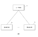
- FIG. 1 is a schematic configuration diagram (system configuration diagram) of an information processing system according to an embodiment of the present invention.
- the information processing system 100 exemplifies n units (n is an arbitrary integer value of 1 or more) of flavor suction tools 1 and a user terminal 2 configured to be communicable. Be prepared.
- Each flavor suction tool 1 includes a battery unit and a cartridge provided with an atomizer for atomizing an aerosol source, and the battery unit and the cartridge unit can be electrically or mechanically (including physically) connected to each other. is there. Further, the battery unit includes a communication unit and can communicate with the user terminal 2. Then, in the information processing system 100 according to the present embodiment of the present invention, the communication between the communication unit of the battery unit and the user terminal 2 is controlled based on the connection state of the battery unit and the cartridge unit in the flavor suction tool 1. To.
- “Flavor suction tool 1” is a device for sucking flavor, and is not limited to, but is intended for, for example, electronic cigarettes, heat-not-burn tobacco, and conventional cigarettes. Further, the flavor suction tool 1 may be an aerosol generation device for generating an aerosol and sucking the generated aerosol. The action of sucking aerosol is called “puff action”, and the number of puff actions is called “puff count”. Aerosol generators are intended, for example, for electronic cigarettes, heat-not-burn tobacco, and medical nebulizers. More specifically, the aerosol generator is, for example, an apparatus that uses electric power to atomize a liquid (aerosol source) to generate an aerosol. Aerosols are atomized aerosol sources and are fine enough to float in a gas.
- the aerosol generated by the aerosol generator may be flavored.
- aerosol generators include heat-not-burn tobacco and electronic cigarettes.
- the aerosol generator includes a type that directly heats tobacco (direct heating), a type that indirectly heats tobacco (indirect heating), and a type that heats a liquid (liquid).
- the aerosol generator may atomize a liquid by generating SAW (Surface Acoustic Wave) using a piezoelectric element substrate having a comb-shaped electrode pair.
- SAW Surface Acoustic Wave
- the flavor suction tool 1a and the flavor suction tool 1n are shown as n units of the flavor suction tool. However, in the following description, when these n flavor suction tools are described without distinction, some reference numerals are omitted and the term "flavor suction tool 1" is simply referred to.
- the user terminal 2 is realized by, for example, a smartphone, a game machine, or a personal computer. Although one user terminal 2 is shown in the figure, the information processing system 100 may include a plurality of user terminals 2.
- the flavor suction tool 1 and the user terminal 2 are related to each other and communicate with each other (including wireless communication). For example, information can be transmitted and received between the flavor suction tool 1 and the user terminal 2 by executing short-range wireless communication such as Bluetooth or BLE (Bluetooth Low Energy) communication.
- short-range wireless communication such as Bluetooth or BLE (Bluetooth Low Energy) communication.
- the transmission and reception of information between the flavor suction tool 1 and the user terminal 2 is not limited to BLE communication, and for example, Wi-Fi [registered trademark], LPWAN (Low Power Wide Area Network), NFC (Near Field Communication), etc. , It may be executed by any communication.
- the transmission / reception of information between the flavor suction tool 1 and the user terminal 2 is not necessarily limited to wireless communication, and may be wired communication such as USB (Universal Serial Bus), Mini USB, Micro USB, and Lightning.
- FIG. 2A is a block diagram of a schematic configuration of a flavor suction tool according to an embodiment of the present invention.
- FIG. 2A shows roughly and conceptually each component included in the flavor suction tool 1, and does not show the exact arrangement, shape, dimensions, positional relationship, etc. of each component and the flavor suction tool 1.
- the flavor aspirator 1 may include components not shown in FIG. 2A, such as cigarette capsules, liquid cartridges and the like.
- the sensor 11 indicates, for example, a sensor that detects information regarding the user's suction.
- the sensor 11 may be any kind of sensor for detecting the user's puff operation, such as a flow rate sensor, a flow velocity sensor, and a pressure sensor.
- the sensor 11 may be a button pressed by the user to perform a puff operation.
- the sensor 11 may be, for example, a suction sensor, or may detect the user's suction to the flavor suction tool 1.
- the sensor 11 may be an airflow sensor or may detect the airflow generated by the user's suction.
- the sensor 11 may be a GPS sensor that measures the position of the flavor suction tool 1.
- the sensor 11 may be a motion sensor that detects the movement of the flavor suction tool 1.
- the motion sensor may be, for example, a gyro sensor for detecting the angle, posture, etc. of the flavor suction tool 1, or an acceleration sensor for detecting the movement of the flavor suction tool 1 in each axial direction. ..
- the motion sensor may be a combination of a gyro sensor, an acceleration sensor, or the like.
- the change unit 12 is a block in which a predetermined change that can be observed externally occurs.
- the changing unit 12 may be an LED (Light Emitting Diode) that emits light in a predetermined color, for example, a blue LED, and the predetermined change may be an LED that emits light in a predetermined color, for example, blue.
- the predetermined color is not limited to blue and may be any color.
- the predetermined change may be a change in the color of light emission or a change in the intensity of light emission according to the intensity (pressure) of suction sensed by the sensor 11.
- the changing unit 12 is not limited to the LED, and may be a light source having another configuration that emits light in a predetermined color.
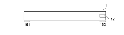
- FIG. 2B is a diagram showing an example of a schematic appearance of the flavor suction tool according to the embodiment of the present invention.
- the flavor suction tool 1 may have a stick shape including, but not limited to, two ends 161 and 162.
- the user will suck to suck one end 161 of the end.
- the user may hold the end 161 to be sucked through a cigarette mouthpiece or the like that can be attached to the end 161.
- the changing portion 12 is preferably provided at the other end 162 of the above two ends.
- the changing portion 12 is at least a part of the outer surface of the flavor suction tool 1, and is, for example, a substantially rectangular shape as shown in FIG. 2B or an annular shape along the outer circumference of the flavor suction tool 1 (not shown). It may have any shape.
- the control unit 13 is a block that causes a predetermined change in the change unit 12 based on at least a signal from the sensor 11. For example, when the magnitude of the signal from the sensor 11 or the strength of suction determined based on the signal is equal to or greater than a predetermined threshold value, the control unit 13 causes the changing unit 12 to emit light of a predetermined color. Good. Further, the control unit 13 may change the color of light emission and the intensity of light emission in the changing unit 12 according to, for example, the magnitude of the signal from the sensor 11 or the intensity of suction determined based on the signal. For example, the control unit 13 may increase the intensity of light emission when the suction is strong, and weaken the intensity of light emission when the suction is weak.
- control unit 13 may divide the suction strength into a plurality of stages, set a predetermined color for each of the plurality of stages, and emit a predetermined color corresponding to the suction strength.
- the control unit 13 may be an electronic circuit module configured as a microprocessor or a microcomputer.
- the communication unit 14 executes wireless communication with the user terminal 2 shown in FIG. 1 or an external device including another computer.
- the communication unit 14 executes an authentication connection (for example, short-range wireless communication such as Bluetooth or BLE communication) which is a setting process of a communication connection between the flavor suction device 1 and the external device with the external device. Executes the pairing process when performing.).
- the authentication connection is, for example, a process required when starting communication between the flavor suction tool 1 and the external device. Encrypted communication can be executed between the flavor suction tool 1 and the external device by appropriately performing the authentication connection.
- the communication unit 11 may receive a request regarding the authentication connection from the external device, or may transmit a request regarding the authentication connection to the external device.
- the communication unit 14 may be realized by using at least a network interface or the like as a hardware resource.
- the control unit 13 can transmit various information detected by the sensor 11 to the user terminal 2 and other computers via the communication unit 14.
- Various types of information transmitted by the control unit 13 to the user terminal 2 and other computers via the communication unit 14 include, for example, output information for outputting the state of the flavor suction tool 1 in the user terminal 2.
- the communication unit 14 can receive various types of information transmitted from the user terminal 2 and other computers.
- the output information may be information indicating the remaining amount of the battery 110.
- the flavor suction tool 1 includes conventional tobacco.
- the conventional cigarette does not include the sensor 11, the control unit 13, and the communication unit 14, but its combustion unit corresponds to the change unit 12. This is because the conventional cigarette burner undergoes a predetermined change in color and temperature based on the user's puff operation.
- the mouthpiece attached to one end of the cigarette is the sensor 11 and the control unit 13 in FIG. 2A. And all or part of the function of the communication unit 14 may be included. According to this configuration, the mouthpiece can transmit various information such as suction information detected by the sensor 11 to the user terminal 2 and another computer.
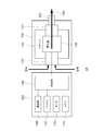
- FIG. 3 is a block diagram showing a schematic configuration of a flavor suction tool according to an embodiment of the present invention.
- the flavor suction tool 1A includes a first member 102 (battery unit) and a second member 104 (cartridge).
- the first member 102 may include a control unit 106, a communication unit 108, a battery 110, a sensor 112, and a memory 114.
- the control unit 13 of FIG. 2A corresponds to the control unit 106 of FIG. 3
- the sensor 11 of FIG. 2A corresponds to the sensor 112 of FIG.
- the communication unit 14 of FIG. 2A corresponds to the communication unit 108 of FIG. .. Note that, in FIGS.
- the first member 102 (battery unit) is described as a configuration included in the flavor suction tool 1A, but is not limited thereto.
- the configuration included in the first member 102 that is, at least one configuration of the control unit 106, the communication unit 108, the battery 110, the sensor 112, or the memory 114 may be an external configuration of the flavor suction tool 1A.
- the second member 104 may include a reservoir 116, an atomizing portion 118, an air intake flow path 120, an aerosol flow path 121, and a mouthpiece portion 122.
- a part of the components contained in the first member 102 may be contained in the second member 104.
- a part of the components contained in the second member 104 may be contained in the first member 102.
- the second member 104 may be configured to be detachable from the first member 102.
- all the components contained in the first member 102 and the second member 104 may be contained in the same housing instead of the first member 102 and the second member 104.
- Reservoir 116 holds an aerosol source.
- the reservoir 116 is composed of a fibrous or porous material and holds an aerosol source as a liquid in the gaps between the fibers and in the pores of the porous material.
- the fibrous or porous material described above for example, cotton, glass fiber, tobacco raw material, or the like can be used.
- the reservoir 116 may be configured as a tank for containing the liquid.
- Aerosol sources are, for example, polyhydric alcohols such as glycerin and propylene glycol, and liquids such as water. If the flavor aspirator 1A is a medical inhaler such as a nebulizer, the aerosol source may also contain a drug for the patient to inhale.
- the aerosol source may include a tobacco ingredient or an extract derived from the tobacco ingredient that releases a flavoring ingredient upon heating.
- the reservoir 116 may have a configuration capable of replenishing the consumed aerosol source.
- the reservoir 116 may be configured so that the reservoir 116 itself can be replaced when the aerosol source is consumed.
- the aerosol source is not limited to a liquid, and may be a solid.
- the reservoir 116 may be, for example, a hollow container that does not use a fibrous or porous material.
- the atomizing unit 118 is configured to atomize the aerosol source to generate an aerosol.
- the atomizing unit 118 produces an aerosol.
- a wick (not shown) may be provided to connect the reservoir 116 and the atomizing section 118. In this case, part of the wick passes through the interior of the reservoir 116 and comes into contact with the aerosol source. The other part of the wick extends to the atomization section 118.
- the aerosol source is carried from the reservoir 116 to the atomizer 118 by the wick's capillary effect.
- the atomizing unit 118 includes a heater electrically connected to the battery 110. The heater is arranged in contact with or in close proximity to the wick.
- the control unit 106 controls the heater of the atomizing unit 118 and atomizes the aerosol source by heating the aerosol source carried through the wick.
- the atomizing unit 118 may be an ultrasonic atomizer that atomizes an aerosol source by ultrasonic vibration.
- An air intake flow path 120 is connected to the atomizing portion 118, and the air intake flow path 120 leads to the outside of the flavor suction tool 1A.
- the aerosol produced in the atomizing section 118 is mixed with the air taken in through the air intake flow path 120.
- the mixed fluid of aerosol and air is pumped into the aerosol flow path 121, as indicated by arrow 124.
- the aerosol flow path 121 has a tubular structure for transporting a mixed fluid of aerosol and air generated in the atomizing portion 118 to the mouthpiece 122.
- the mouthpiece 122 is located at the end of the aerosol flow path 121, and is configured to open the aerosol flow path 121 to the outside of the flavor suction tool 1A. The user takes in the air containing the aerosol into the oral cavity by sucking the mouthpiece 122 by holding it.
- the communication unit 108 communicates with the user terminal and other computers.
- the communication unit 108 may be realized by using at least a network interface or the like as a hardware resource.
- the battery 110 supplies electric power to each component of the flavor suction tool 1A such as the communication unit 108, the sensor 112, the memory 114, and the atomizing unit 118.
- the battery 110 may be charged by connecting to an external power source via a predetermined port (not shown) of the flavor suction tool 1A. Only the battery 110 may be removed from the first member 102 or the flavor aspirator 1A or may be replaced with a new battery 110. Further, the battery 110 may be replaced with a new battery 110 by replacing the entire first member 102 with a new first member 102.
- the sensor 112 may include a pressure sensor that detects pressure fluctuations in the air intake flow path 120 and / or the aerosol flow path 121, or a flow rate sensor that detects the flow rate.
- the sensor 112 may also include a weight sensor that detects the weight of a component such as the reservoir 116.
- the sensor 112 may also be configured to detect a puffing motion by the user using the flavor suction tool 1A.
- the sensor 112 may also be configured to integrate the energization time on the atomizing section 118.
- the sensor 112 may also be configured to detect the height of the liquid level in the reservoir 116.
- the sensor 112 may also be configured to detect the SOC (State of Charge, charging state), current integrated value, voltage, and the like of the battery 110.
- the current integration value may be obtained by a current integration method, an SOC-OCV (Open Circuit Voltage, open circuit voltage) method, or the like.
- the sensor 112 may also be a user-operable operation button or the like.
- the control unit 106 may be an electronic circuit module configured as a microprocessor or a microcomputer.
- the control unit 106 may be configured to control the operation of the flavor suction tool 1A according to a computer executable command stored in the memory 114.
- the memory 114 is a storage medium such as a ROM, RAM, or flash memory.
- the memory 114 may store setting information and the like necessary for controlling the flavor suction tool 1A.
- the memory 114 stores, for example, action information regarding a predetermined action in the flavor suction tool 1A.
- the predetermined action in the flavor suction tool 1A includes, for example, the following actions (1) to (5).
- (1) The first member 102 shown in FIGS. 3 and 4 and the second member 104 having the atomizing portion 118 for atomizing the aerosol source are connected or reconnected (the first).
- the first member 102 and the second member 104 are electrically or mechanically (including physically) connected, or the first member 102 and the second member 104 are electrically connected.
- the authentication process is executed when connected mechanically (including physical), this authentication process was successful, etc.
- the puff operation was executed in the flavor suction tool 1A (for example, the atomizing unit 118 heats the heater to atomize the aerosol source, etc.).
- Charging is executed for the battery 110 included in the flavor suction tool 1A (for example, charging is executed in the battery 110 by connecting the flavor suction tool 1A to a charging device (not shown), etc. ) Or, it is detected that the remaining amount of the battery 110 is equal to or more than the predetermined value or less than the predetermined value.
- the predetermined value may be indicated by a ratio such as 70%, or may be indicated by a capacity such as 1000 mAh.
- the predetermined value may be any value.
- the control unit 106 measures the remaining amount of the battery 110 that supplies electric power to the flavor suction tool 1A shown in FIGS. 3 and 4.
- the control unit 106 measures the remaining amount of the battery based on the information such as the SOC, the integrated current value, and the voltage of the battery 110 detected by the sensor 112 shown in FIGS. 3 and 4, for example.
- the remaining amount of the battery may be indicated as a percentage (%) of how much of the total amount remains, or other display method may be used.
- the memory 114 stores various information such as a control method of the communication unit 108 (modes such as light emission, vocalization, vibration, etc.), a value detected by the sensor 112, and a heating history of the heater by the atomizing unit 118. May be good.
- the control unit 106 reads information from the memory 114 as needed and uses it for controlling the flavor suction tool 1A, and stores the information in the memory 114 as needed.
- FIG. 4 is a block diagram showing another schematic configuration of the flavor suction tool according to the embodiment of the present invention.
- the flavor suction tool 1B includes a third member 126 in addition to the configuration of the flavor suction tool 1A of FIG.
- the third member 126 may include a flavor source 128.
- the flavor source 128 may contain a flavor component contained in the cigarette.
- the aerosol flow path 121 extends over the second member 104 and the third member 126.
- the mouthpiece 122 is provided on the third member 126.
- the flavor source 128 is a component for imparting a flavor to the aerosol.
- the flavor source 128 is arranged in the middle of the aerosol flow path 121.
- the mixed fluid of aerosol and air generated by the atomizing unit 118 (hereinafter, it should be noted that the mixed fluid may be simply referred to as aerosol) flows through the aerosol flow path 121 to the mouthpiece 122.
- the flavor source 128 is provided downstream of the atomizing portion 118 with respect to the flow of the aerosol. In other words, the flavor source 128 is located closer to the mouthpiece 122 in the aerosol flow path 121 than the atomizing portion 118. Therefore, the aerosol produced by the atomizing section 118 passes through the flavor source 128 before reaching the mouthpiece 122.
- the flavor component contained in the flavor source 128 is imparted to the aerosol.
- the flavor suction tool 1B is a heat-not-burn tobacco
- the flavor source 128 may be derived from tobacco, such as chopped tobacco or a processed product obtained by molding a tobacco raw material into granules, sheets, or powders. ..
- the flavor source 128 may also be of non-tobacco origin made from plants other than tobacco (eg, mint, herbs, etc.).
- flavor source 128 contains a tobacco component.
- the flavor source 128 may contain a perfume component such as menthol.
- the reservoir 116 may also contain substances containing flavor components.
- the flavor suction tool 1B may be configured to hold a tobacco-derived flavoring substance in the flavor source 128 and contain a non-tobacco-derived flavoring substance in the reservoir 116.
- the user can take in the air containing the flavored aerosol into the oral cavity by holding the mouthpiece 122 and sucking it.
- the control unit 106 is configured to control the flavor suction tools 1A and 1B (hereinafter, collectively referred to as "flavor suction tool 1") according to the embodiment of the present disclosure by various methods.
- FIG. 5 is a diagram showing another example of the schematic appearance of the flavor suction tool according to the embodiment of the present invention.
- FIG. 6 is another example of the schematic appearance of the flavor suction tool in a state of holding the aerosol-forming base material according to the embodiment of the present invention.
- the flavor suction tool 1 produces an aerosol containing a flavor by heating an aerosol-producing base material such as a suction article having a flavor-generating base material such as an aerosol source and a filler containing the flavor source. Configured to generate.
- the suction article 140 may be used as an aerosol-producing base material.
- the suction article 140 is only an example of an aerosol-forming substrate.
- the aerosol source contained in the aerosol-forming substrate may be a solid or a liquid.
- the aerosol source may be, for example, a polyhydric alcohol such as glycerin or propylene glycol, a liquid such as water, or a mixture thereof.
- the aerosol source may include a tobacco raw material that releases a flavor component by heating or an extract derived from the tobacco raw material. If the flavor aspirator 1 is a medical inhaler such as a nebulizer, the aerosol source may include a drug for the patient to inhale.
- the aerosol-forming substrate may not contain a flavor source.
- the flavor suction tool 1 has a top housing 131A, a bottom housing 131B, a cover 132, a switch 133, and a lid 134.
- the top housing 131A and the bottom housing 131B are connected to each other to form the outermost housing 131 of the flavor suction tool 1.
- the housing 131 may be sized to fit in the user's hands. In this case, when the user uses the flavor suction tool 1, the user can hold the flavor suction tool 1 by hand and suck the aerosol.
- the top housing 131A has an opening (not shown), and the cover 132 is coupled to the top housing 131A so as to close the opening.
- the cover 132 has an opening 132B into which the suction article 140 can be inserted.
- the lid 134 is configured to open and close the opening 132B of the cover 132.
- the lid 134 is attached to the cover 132 and is configured to be movable along the surface of the cover 132 between the first position for closing the opening 132B and the second position for opening the opening 132B. ..
- the switch 133 is used to switch the operation of the flavor suction tool 1 on and off.
- the user operates the switch 133 with the suction article 140 inserted in the opening 132B to supply electric power from the battery (not shown) to the heating unit (not shown).
- the suction article 140 can be heated without burning.
- an aerosol is generated from the aerosol source contained in the suction article 140, and the flavor of the flavor source is incorporated into the aerosol.
- the user can suck the aerosol containing the flavor by sucking the portion of the suction article 140 (the portion shown in FIG. 6) protruding from the flavor suction tool 1.
- the direction in which the aerosol-forming base material such as the suction article 140 is inserted into the opening 132B is referred to as the longitudinal direction of the flavor suction tool 1.
- the configuration of the flavor suction tool 1 shown in FIGS. 5 and 6 is only an example of the configuration of the flavor suction tool according to the present disclosure.
- the flavor suction tool according to the present disclosure can generate an aerosol by heating an aerosol-producing base material containing an aerosol source, and the produced aerosol can be sucked by a user in various forms. Can be configured.
- FIG. 7 is a block diagram of a schematic configuration of a user terminal according to an embodiment of the present invention. It should be noted that FIG. 7 shows roughly and conceptually each component included in the user terminal 2, and does not show the exact arrangement, shape, dimensions, positional relationship, etc. of each component and the user terminal 2. I want to. Also note that the user terminal 2 may include components (not shown).
- the example of the user terminal 2 is one computer such as a smartphone, a tablet, or a personal computer, but the present invention is not limited to this.
- the detection unit 21 described later may be realized by a digital camera externally connected to the computer.
- the detection unit 21 detects at least a part of the flavor suction tool 1, for example, an externally observable predetermined change occurring in the change unit 12.
- the detection unit 21 may be realized by using at least a digital camera, a temperature sensor, or the like as hardware resources.
- the output unit 22 executes the message output process based on the output information notified from the flavor suction tool 1 shown in FIG.
- the output unit 22 may execute the voice output process based on the output information notified from the flavor suction tool 1.
- the output unit 22 displays information indicating that the predetermined change is detected.
- the output unit 22 may be realized by using at least a display (including, for example, a touch panel display) as a hardware resource.
- the input unit 23 receives input from the user.
- the input unit 23 may be realized by using at least a keyboard, a mouse, a touch panel display, or the like as hardware resources.
- the recording unit 24 stores programs, information, and the like.
- the recording unit 24 may be realized by using at least an HDD (Hard Disk Drive), an SSD (Solid State Drive), a memory, or the like as hardware resources.
- HDD Hard Disk Drive
- SSD Solid State Drive
- memory or the like as hardware resources.
- the communication unit 25 communicates with another computer.
- the communication unit 25 may be realized by using at least a network interface or the like as a hardware resource.
- the control unit 26 performs various controls.
- the control unit 26 may be configured to transmit and receive information via the communication unit 25.
- the output unit 22 can output information based on the received output information.
- the control unit 26 may be configured to determine, for example, how to suck the user.
- the output unit 22 can further display the result of the determination.
- the control unit 26 may be configured to allow the user to select one of the plurality of sucking methods via the input unit 23.
- the output unit 22 can further display information based on the selected sucking method.
- the control unit 26 may be realized by using at least a processor or the like as a hardware resource.
- various functions of the user terminal 2 may be realized by using an application running on the user terminal.
- the user terminal 2 may download an application and realize various functions by the downloaded application. Further, the user terminal 2 may realize various functions by downloading a program for realizing various functions of the user terminal 2 and executing the downloaded program.
- the user terminal 2 may realize these functions by PWA (Progressive Web Apps).
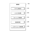
- FIG. 8 is a schematic configuration diagram showing an example of the functional configuration of the control unit according to the embodiment of the present invention.
- the control unit 106 functionally includes a system control unit 200, a battery control unit 202, a cartridge control unit 204, a communication control unit 206, and an interface detection unit 208.
- control unit 106 can be realized, for example, by the CPU or the like executing a program stored in the memory 114 shown in FIGS. 3 and 4. Further, the control unit 106 may be realized by downloading a program used for processing in the control unit 106 and executing the downloaded program.
- the control unit 13 shown in FIG. 2A may functionally include a system control unit 200, a battery control unit 202, a cartridge control unit 204, a communication control unit 206, and an interface detection unit 208.
- Each of the above-mentioned functions included in the control unit 106 or the control unit 13 may be provided in another configuration.
- at least one configuration of the communication control unit 206 or the cartridge control unit 204 may be provided by, for example, the communication unit 108 shown in FIGS. 3 and 4.
- the interface detection unit 208 may be provided with, for example, the sensor 112 shown in FIGS. 3 and 4.
- the communication between the flavor suction tool 1 and the user terminal 2 may be any communication such as short-range wireless communication, but the case of BLE (Bluetooth Low Energy) communication will be described below as an example. ..
- the system control unit 200 controls, for example, each function included in the control unit 106 (in the example of FIG. 8, the battery control unit 202, the cartridge control unit 204, the communication control unit 206, and the interface detection unit 208). Further, the system control unit 200 controls execution of various control programs, embedded operating system (OS) programs, and the like, for example. For example, when the system control unit 200 detects various request signals such as a start instruction, it reads a program, an OS code, and the like, allocates the processing time and resources required for executing them, and so on, in the execution unit of the program. Process a process.
- the system control unit 200 is not limited to these examples, and can control various functions and various processes required for the operation of the flavor suction tool 1.
- the battery control unit 202 supplies power from, for example, a battery (described as a battery or the like) provided in the battery 110 of FIGS. 3 and 4 and the flavor suction tool 1 shown in FIGS. 5 and 6, and charges the battery or the like.
- the battery control unit 202 controls, for example, power supply from a battery or the like to each element such as a heater provided in the flavor suction tool 1 illustrated in FIGS. 3 to 6.
- the battery control unit 202 is pressed when suction to the suction port 31 illustrated in FIGS. 3 or 4 is detected or the switch 133 illustrated in FIGS. 5 or 6 is pressed. If so, power is supplied from the battery or the like to the heater.
- the battery control unit 202 controls charging of the battery or the like from an external power source (not shown). Further, the battery control unit 202 may execute, for example, a function of detecting the remaining amount of the battery or a function of protecting the battery. Further, the battery control unit 202 may control the heating of the heater provided in the flavor suction tool 100, for example.
- the battery control unit 202 is not limited to these examples, and can execute various controls on the battery.
- the cartridge control unit 204 determines, for example, the connection state between the first member 102 shown in FIGS. 3 and 4 and the second member 104 including the atomizing unit 118 for atomizing the aerosol source. For example, the cartridge control unit 204 determines whether or not the first member 102 and the second member 104 are electrically or mechanically (including physically) connected.
- the electrical connection between the first member 102 and the second member 104 includes, for example, that the first member 102 and the second member 104 are energized.
- first member 102 and the second member 104 are mechanically (including physically) connected means that, for example, the first member 102 and the second member 104 are fitted together. By doing so, it includes being connected to each other. Further, when the first member 102 and the second member 104 are mechanically (including physically) connected, for example, the first member 102 and the second member 104 are screwed together. By doing so, it may include being connected to each other.
- the first member 102 has a female connector at a portion adjacent to the second member 104, and the female connector has a spiral groove, while the second member 104 has a spiral groove.
- a male connector is provided at a portion adjacent to the first member 102, and the male connector has a spiral protrusion.
- first member 102 and the second member 104 are connected by screwing the female connector of the first member 102 and the male connector of the second member 104.
- the first member 102 may have a male connector
- the second member 104 may have a female connector.
- the cartridge control unit 204 executes the authentication process when, for example, the first member 102 and the second member 104 are electrically or mechanically connected, the authentication process is successful. , It is determined that the first member 102 and the second member 104 are connected. On the other hand, when the authentication process fails, the cartridge control unit 204 determines that the first member 102 and the second member 104 are not connected. The details of the authentication process will be described later.
- the cartridge control unit 204 determines whether or not a predetermined period (for example, 10 seconds, 1 minute, 5 minutes, etc.) has elapsed after the connection between the first member 102 and the second member 104 is released. ..
- the cartridge control unit 204 counts the elapsed time after detecting that the connection between the first member 102 and the second member 104 has been released.
- Information about a predetermined time is stored in the memory 114 shown in FIGS. 3 and 4.
- the cartridge control unit 204 refers to the information about the predetermined time stored in the memory 114 and compares the counted elapsed time with the predetermined time.
- the cartridge control unit 204 executes the authentication process of the second member 104 (cartridge).
- the cartridge control unit 204 confirms, for example, the validity of the first member 102 as a connection target with respect to the second member 104.
- the cartridge control unit 204 refers to the identification information of one or a plurality of second members 104 that can be connected to the first member 102, which are recorded in advance in the memory 114 shown in FIGS. 3 and 4. Thereby, it is determined whether or not the specific second member 104 has the legitimacy as a connection target.
- the cartridge control unit 204 has legitimacy for the second member 104 as a connection target based on the expiration date of the aerosol source contained in the reservoir 116 of the second member 104 to which the first member 102 is connected. May be determined. For example, the cartridge control unit 204 acquires information on the expiration date of the aerosol source from the second member 104 when the first member 102 and the second member 104 are electrically or mechanically connected to each other. .. The cartridge control unit 204 refers to the acquired information on the expiration date, and if the expiration date of the aerosol source contained in the reservoir 116 of the second member 104 to be connected to the first member 102 has not expired, the cartridge control unit 204 has not expired.
- the cartridge control unit 204 sets the second member 104 as the connection target. Judge that it does not have the validity of. Further, the cartridge control unit 204 acquires, for example, the remaining amount information regarding the remaining amount of the aerosol source contained in the reservoir 116 of the second member 104, and based on the acquired remaining amount information, the second member as a connection target. The validity of the member 104 may be determined.
- the communication control unit 206 is connected to the flavor suction tool 1 based on the connection state between the first member 102 shown in FIGS. 3 and 4 and the second member 104 including the atomizing unit 118 for atomizing the aerosol source. Controls communication with the user terminal 2.
- the communication control unit 206 can control not only wireless communication but also wired communication.
- the communication control unit 206 executes the "authentication connection” which is the setting process of the communication connection between the flavor suction tool 1 and the user terminal 2.
- the communication control unit 206 authenticates and connects, for example, the flavor suction tool 1 and the user terminal 2.
- the flavor suction tool 1 and the user terminal 2 are in the "authentication connection state”.
- Bluetooth communication is executed, for example, in a unit called a piconet.
- the user terminal 2 is called a "master” and the flavor suction tool 1 is called a "slave".
- the master has the initiative in communication, and information transmission from the master to the slave is executed at an arbitrary timing.
- the information from the slave to the master is executed based on the instruction from the master (request regarding the authentication connection).
- the user terminal 2 does not necessarily have to take the initiative in the communication.
- the flavor suction tool 1 may take the initiative in communication, and information may be transmitted from the flavor suction tool 1 to the user terminal 2 at an arbitrary timing.
- a shared secret information generated by a random number is exchanged between the master and the slave. Then, the communication between the master and each slave is encrypted based on the link key.
- the procedure for such key exchange and establishment of communication connection settings between the master and the slave is "authentication connection”.
- the master and the slave execute communication so as to synchronize the timing of information transmission (TX) or the timing of information reception (RX) with each other.
- transmission frequency change is provided as one of the low power consumption operations.
- the transmission frequency change is an operation of suppressing power consumption by thinning out the response communication that must respond to the inquiry from the master when the slave does not have the information to be transmitted to the master.
- the slave when communicating between the slave and the master, the slave needs to respond to the master at each preset communication interval L of the master. For example, when the slave does not respond to the inquiry from the master (for example, when the slave does not respond for the preset number of times of communication interruption), the slave disconnects from the master. However, even when there is no information to be transmitted (for example, updated information), it leads to unnecessary power consumption for the slave to respond to and communicate with the inquiry from the master.
- the slave can maintain the communication connection up to 4 times in response to the inquiry from the master even if the slave does not respond. It is possible. In this way, the slave can thin out the response communication and can suppress the power consumption. Even when the communication is thinned out based on the change in the transmission frequency, the slave executes, for example, the communication for maintaining the communication connection with the master with the minimum power consumption.
- forced transmission even if communication is thinned out based on a change in transmission frequency, predetermined information that the slave should send to the master is transmitted to the master at the next transmission timing in the state before thinning out. It is an operation to do. For example, when the slave sets the transmission frequency setting value to "4" by changing the transmission frequency, the response transmission is thinned out.
- forced transmission even during the communication thinning period (that is, when transmission frequency change is set), transmission should be performed to the master at the next transmission timing in the state before thinning. Information can be sent.
- the transmission frequency change and the forced transmission in the communication according to the embodiment of the present invention are operations that enable efficient information transmission while being a low power consumption operation.
- the communication control unit 206 may execute the initial setting of the setting contents related to the communication executed between the flavor suction tool 1A and the user terminal 2, or the communication unit 108 or the communication control unit shown in FIGS. 3 and 4. 206 may be executed.
- the initial setting of communication is based on the information recorded in advance in the flavor suction tool 1A, the information separately input by the user, the information included in the request for authentication connection from the user terminal 2, and the like. Will be executed.
- control of the communication between the flavor suction tool 1 and the user terminal 2 includes, for example, the “restriction” of the communication.
- the “restriction” of communication includes, for example, “restricting the transmission of information” between the flavor suction tool 1 and the user terminal 2.
- the “restriction” of the communication includes, for example, “restricting the authentication connection” which is a setting process of the communication connection between the flavor suction tool 1 and the user terminal 2.
- the "control" of the communication between the flavor suction tool 1 and the user terminal 2 includes, for example, “changing the setting contents related to the communication”.
- “changing the setting contents related to communication” includes, for example, “changing the frequency of communication” between the flavor suction tool 1 and the user terminal 2.
- “changing the communication frequency” includes, for example, “changing the response frequency” of the flavor suction tool 1 to an inquiry from the user terminal 2.
- the communication control unit 206 may execute wireless communication according to the response frequency to be changed.
- “changing the communication frequency” includes, for example, “changing the transmission frequency setting value” between the user terminal 2 and the flavor suction tool 1.
- the communication control unit 206 may execute wireless communication according to the transmission frequency setting value to be changed.
- “changing the communication frequency” includes, for example, “changing the communication interval” between the user terminal 2 and the flavor suction tool 1.
- the communication control unit 206 may execute wireless communication according to the communication interval to be changed.
- the "restriction of the authentication connection” includes “waiting for the authentication connection” in the flavor suction tool 1, and includes the flavor suction tool 1 waiting for a response to the request regarding the authentication connection from the user terminal 2.
- the "restriction" of the communication between the flavor suction tool 1 and the user terminal 2 includes, for example, the “stop” of the communication. Then, “stopping” the communication includes, for example, “stopping the transmission of information” from the flavor suction tool 1 to the user terminal 2. Further, the “restriction” of the communication includes, for example, “stopping the authentication connection” which is a setting process of the communication connection between the flavor suction tool 1 and the user terminal 2. Specifically, the communication control unit 206 may stop the communication between the flavor suction tool 1 and the user terminal 2, for example. The communication control unit 206 may control communication so that, for example, the communication unit 108 shown in FIGS. 3 and 4 stops transmitting information to the user terminal 2. The communication control unit 206 may control the communication so that the communication unit 108 stops receiving information from the user terminal 2.
- the power consumption of the flavor suction tool 1A is reduced, and the battery consumption is also reduced.
- the power consumption of the battery 110 is larger in the transmission of information than in the reception of information, the consumption of the battery 110 can be further reduced by preferentially limiting or stopping the transmission of information.
- control of communication includes prohibiting the transmission of at least a part of the information that can be transmitted to the user terminal 2 by the communication unit 108.
- the communication control may allow the communication unit 108 to transmit only the response to the request for the authentication connection to the user terminal 2 to the user terminal 2.
- the communication control unit 206 may allow the communication unit 108 to receive a request regarding an authentication connection from the user terminal 2, for example, when the flavor suction tool 1 is performing a puff operation.
- the communication control unit 206 may execute the authentication connection (for example, respond to the request) after the heating of the heater is completed.
- the interface detection unit 106 detects a predetermined action in the flavor suction tool 1.
- the interface detection unit 106 detects at least one of the above-mentioned actions (1) to (5), for example.
- the interface detection unit 106 is connected or reconnected to the first member 102 shown in FIGS. 3 and 4 and the second member 104 including the atomizing unit 118 for atomizing the aerosol source. Is detected.
- the interface detection unit 106 detects that the first member 102 and the second member 104 are electrically connected by energizing the first member 102 and the second member 104. Further, when the interface detection unit 106 executes the authentication process when the first member 102 and the second member 104 are electrically or mechanically connected to each other, if the authentication process is successful, the interface detection unit 106 becomes the first. It may be detected that the member 102 of 1 and the member 104 of the second member are connected.
- the interface detection unit 106 determines that the puff operation has been executed in the flavor suction tool 1A, for example, based on the heating state of the heater included in the atomizing unit 118 shown in FIGS. 3 and 4.
- the interface detection unit 106 detects that a predetermined button (not shown) provided on the flavor suction tool 1A has been pressed.
- the interface detection unit 106 detects that the flavor suction tool 1 is in a predetermined posture based on the detection result of the sensor 112. Specifically, the interface detection unit 106 indicates that the flavor suction tool 1A has a predetermined angle when, for example, the sensor 112, which is a motion sensor, grasps the movement of the flavor suction tool 1A in each axial direction. Detect. Further, the interface detection unit 106 may detect that the flavor suction tool 1A has vibrated by the sensor 112, which is a motion sensor, for example.
- control unit 106 may use the following method for controlling communication. That is, as an operation in the processing of each function of the control unit 106, each functional element, for example, each unit constituting the control unit 106 of FIG. 8 is treated as one processing or processing group, and the system satisfies the time constraint condition. A method of operating the whole (for example, a method represented by a real-time system) may be used.
- the battery control unit 202 when the battery control unit 202 is treated as one processing group and the communication control unit 206 is treated as one processing group, these two processing groups may be required to process at the same time.
- the communication control unit 206 receives a response request from the user terminal 2 by wireless communication while the puff operation is being executed by the flavor suction tool 1, it is determined in advance which process should be prioritized. There is a need.
- prioritizing in the treatment as the treatment having the highest priority, there is a response to an abnormal state in the flavor suction tool 1.
- priority is set in the order of heater heating processing, aerosol generation device connection state detection processing, operation detection processing for user operation, and communication response request processing from the user terminal 2. May be good.
- the entire system can be operated so as to satisfy the above-mentioned time constraint condition.
- the execution time in each process may be predicted in advance so that the time constraint condition can be satisfied, and the order of the processes may be adjusted so that the time constraint can be observed for all the processes having the time constraint condition.
- the process having a higher priority may execute the process with priority over the process having a lower priority.
- the high-priority processing may be controlled so as to interrupt the processing even while the low-priority processing is being executed.
- a process having a higher priority may be executed exclusively for a process having a lower priority.
- the communication control unit 206 receives a response request from the user terminal 2 by wireless communication in a state where the puff operation is executed in the flavor suction tool 1, in advance. It is possible to execute each process at a determined priority and satisfy the time constraint condition.
- control unit 106 may control communication as follows. For example, the control unit 106 is in a sleep state (temporarily stopped operation) from a state in which the flavor suction tool 1 is activated (a state in which heating of the heater and other necessary processing can be executed for the puff operation by the user). When the state shifts to the state of waiting in the power saving state), the setting contents related to the communication executed between the flavor suction tool 1A and the user terminal 2 may be changed as the control of the communication. Further, for example, the control unit 106 controls communication when a predetermined period (for example, 1 minute, 5 minutes, etc.) elapses after the connection between the first member 102 and the second member 104 is released. As a result, communication may be stopped.
- a predetermined period for example, 1 minute, 5 minutes, etc.
- the predetermined period is not limited to 1 minute or 5 minutes, and may be any period and can be set arbitrarily. Even if the control unit 106 stops communication as a control of communication, for example, when a predetermined action that can be determined that the user does not use the flavor suction tool 1 is detected, even when the predetermined period has not elapsed. Good. As a predetermined action in which the user can determine that the flavor suction tool 1 is not used, for example, the third member 126 in the case of the flavor suction tool 1 to FIG. 3 and the suction article 140 in the case of FIG. 6 are removed. However, the action is not limited to this, and any action may be used.
- FIG. 9 is a flowchart showing an example of communication control processing according to the first embodiment of the present invention.
- the user first presses, for example, a power button (not shown) provided on the outer surface of the flavor suction tool 1, thereby causing the flavor suction tool 1 to be pressed.
- the activation process of the flavor suction tool 1 is similarly executed in the communication control process according to each embodiment described later.
- the activation process of the flavor suction tool 1 is not limited to pressing the power button, and may be, for example, a puff operation for the flavor suction tool 1, and any method as long as the flavor suction tool 1 is activated. May be.
- step S3 the flavor suction tool 1 determines, for example, the connection state between the first member 102 (battery unit) shown in FIGS. 3 and 4 and the second member 104 (cartridge).
- the cartridge control unit 204 determines whether or not the first member 102 and the second member 104 are electrically or mechanically (including physically) connected.
- the flavor suction tool 1 controls communication between the flavor suction tool 1 and the user terminal 2 based on the connection state between the first member 102 and the second member 104. For example, when the first member 102 and the second member 104 are not connected (for example, when the connection is disconnected), the flavor suction tool 1 is located between the flavor suction tool 1 and the user terminal 2. Restrict communication. For example, the flavor suction tool 1 may stop the communication between the flavor suction tool 1 and the user terminal 2 as a limitation of communication, and the flavor suction tool 1 has the communication unit 108 shown in FIGS. Transmission of information to the user terminal 2 may be stopped or restricted, or communication may be executed according to the setting contents changed by the communication control unit 206. Further, the flavor suction tool 1 may limit or stop the authentication connection between the flavor suction tool 1 and the user terminal 2 as a communication limitation.
- the flavor suction tool 1 controls the communication between the flavor suction tool 1 and the user terminal 2 based on the connection state between the battery unit and the cartridge. Therefore, since the increase in the power consumption of the flavor suction tool 1 can be suppressed, the consumption of the battery 110 included in the flavor suction tool 1 can be reduced.
- the second embodiment is a communication control process when the first member 102 and the second member 104, which are not connected to each other, are connected and then the communication between the flavor suction tool 1 and the user terminal 2 is started. Is shown.
- FIG. 10 is a flowchart showing an example of communication control processing according to the second embodiment of the present invention.
- FIG. 10 illustrates a case where the authentication connection is restricted as the control of communication.
- the limitation of the authentication connection includes waiting for the authentication connection in the flavor suction tool 1.
- the control of communication is not limited to limiting the authentication connection.
- the communication control may be, for example, limiting or stopping the communication between the flavor suction tool 1 and the user terminal 2, and the communication unit 108 shown in FIGS. 3 and 4 informs the user terminal 2. May be restricted or stopped, communication may be executed according to the setting contents changed by the communication control unit 206, or the authentication connection may be stopped.
- the flavor suction tool 1 may change the setting contents related to the wireless communication between the flavor suction tool 1 and the user terminal 2 as the control of communication.
- the flavor suction tool 1 may change the response frequency of the flavor suction tool 1 to an inquiry from the user terminal 2 when changing the transmission frequency.
- the flavor suction tool may change the transmission frequency setting value between the user terminal 2 and the flavor suction tool 1 when changing the transmission frequency.
- the flavor suction tool may change the communication interval between the user terminal 2 and the flavor suction tool 1 when the transmission frequency is changed.
- the transmission and reception of information between the flavor suction tool 1 and the user terminal 2 is thinned out, so that the power consumption related to the communication in the flavor suction tool 1 can be reduced. Therefore, the power consumption of the battery 110 of the flavor suction tool 1 is reduced.
- step S11 first, the user activates the first member 102 by, for example, pressing a power button (not shown) provided on the outer surface of the first member 102.
- the means for activating the first member 102 is not limited to pressing the power button, and may be any means.
- step S13 the flavor suction tool 1 proceeds to step S15 when the first member 102 and the second member 104 are connected (in the case of Yes in step S13).
- the flavor suction tool 1 when the first member 102 and the second member 104 are not connected (No in step S13), the first member 102 and the second member 104 are connected. Wait until it is done.
- step S15 the flavor suction tool 1 executes an authentication connection with the user terminal 2. Then, in step S17, the flavor suction tool 1 determines whether or not the authentication connection is completed.
- the flavor suction tool 1 proceeds to step S19 when the authentication connection is completed (in the case of Yes in step S17). On the other hand, when the authentication connection with the user terminal 2 is not completed (No in step S17), the flavor suction tool 1 waits until the authentication connection is completed.
- step S19 the flavor suction tool 1 starts transmitting and receiving predetermined information to and from the user terminal 2.
- the predetermined information includes, for example, suction information and the like.
- the flavor suction tool 1 starts communication with the user terminal 2 by using the connection between the first member 102 and the second member 104 as a trigger, so that the first member 102 and the second member 104 When is not connected, the communication with the user terminal 2 can be controlled, and the power consumption related to the communication in the flavor suction tool 1 can be reduced. Therefore, it is possible to reduce the consumption of the battery 110.
- FIG. 11 is a flowchart showing an example of communication control processing according to the third embodiment of the present invention. Note that FIG. 11 illustrates a case where communication is restricted as communication control. In the third embodiment, the control of communication is not limited to this. Further, since step S21 shown in FIG. 11 is the same as step S1 shown in FIG. 9, the description thereof will be omitted.
- step S23 the flavor suction tool 1 executes, for example, an authentication connection with the user terminal 2.
- the flavor suction tool 1 starts transmitting / receiving predetermined information by Bluetooth to / from the user terminal 2.
- step S25 the flavor suction tool 1 proceeds to step S27 when the connection between the first member 102 and the second member 104 is disconnected (in the case of Yes).
- the flavor suction tool 1 is not disconnected from the first member 102 and the second member 104 (the connection is maintained) (No)
- the flavor suction tool 1 is the user.
- the transmission and reception of predetermined information by Bluetooth is continued with the user terminal 2 without restricting the communication with the terminal 2.
- the flavor suction tool 1 limits communication with the user terminal 2.
- the flavor suction tool 1 limits the transmission of information from the flavor suction tool 1 to the user terminal 2.
- the limitation of communication is not limited to limiting the transmission of information.
- the communication restriction may be, for example, to stop the communication between the flavor suction tool 1 and the user terminal 2, and the communication unit 108 shown in FIGS. 3 and 4 transmits information to the user terminal 2. This may be stopped, communication may be executed according to the setting contents changed by the communication control unit 206, and the authentication connection may be restricted or stopped.
- the flavor suction tool 1 may change the setting contents related to wireless communication between the flavor suction tool 1 and the user terminal 2 as a communication limitation.
- the flavor suction tool 1 may change the response frequency of the flavor suction tool 1 to an inquiry from the user terminal 2 when changing the transmission frequency.
- the flavor suction tool may change the transmission frequency setting value between the user terminal 2 and the flavor suction tool 1 when changing the transmission frequency.
- the flavor suction tool may change the communication interval between the user terminal 2 and the flavor suction tool 1 when the transmission frequency is changed.
- the transmission and reception of information between the flavor suction tool 1 and the user terminal 2 is thinned out, so that the power consumption related to the communication in the flavor suction tool 1 can be reduced. Therefore, the power consumption of the battery 110 of the flavor suction tool 1 is reduced.
- the flavor suction tool 1 when the flavor suction tool 1 starts communication with the user terminal 2 and then the connection between the first member 102 and the second member 104 is released, the user Restrict communication with terminal 2. Therefore, when the connection between the first member 102 and the second member 104 is released, the flavor suction tool 1 limits the communication between the flavor suction tool 1 and the user terminal 2. Therefore, since the power consumption related to the communication in the flavor suction tool 1 can be reduced, the consumption of the battery 110 can be reduced.
- FIG. 12 is a flowchart showing an example of communication control processing according to the fourth embodiment of the present invention. Note that FIG. 12 illustrates a case where communication is restricted as communication control, but in the fourth embodiment, communication control is not limited to communication restriction. Since steps S31 to S35 and S39 shown in FIG. 12 are the same as steps S21 to S27 shown in FIG. 11, description thereof will be omitted.
- step S37 the flavor suction tool 1 determines that a predetermined period (for example, 10 seconds, 1 minute, 5 minutes, etc.) has elapsed after the connection between the first member 102 and the second member 104 is released. (In the case of Yes in step S37), the process proceeds to step S39. On the other hand, in the flavor suction tool 1, a predetermined period (for example, 10 seconds, 1 minute, 5 minutes, etc.) has not elapsed after the connection between the first member 102 and the second member 104 is released. When determining (No in step S37), the flavor suction tool 1 communicates with the user terminal 2 by Bluetooth without restricting the communication with the user terminal 2 until a predetermined period elapses. continue.
- a predetermined period for example, 10 seconds, 1 minute, 5 minutes, etc.
- abnormal heat generation of the battery 110 shown in FIGS. 3 and 4 is caused until communication is restricted, that is, until it is determined that a predetermined period has elapsed.
- the flavor suction tool 1 can notify the user terminal 2 of the abnormality of the battery 110.
- the flavor suction tool 1 prevents the communication between the flavor suction tool 1 and the user terminal 2 from being stopped immediately after the connection between the first member 102 and the second member 104 is released. it can. For example, when the user removes the cartridge from the battery unit and then immediately installs a new cartridge in order to replace the cartridge of the flavor suction tool 1, it is not necessary to bother to restrict communication.
- the flavor suction tool 1 can continue the communication without restricting the communication, for example, when the user replaces the cartridge.
- FIG. 13 is a flowchart showing an example of communication control processing according to the fifth embodiment of the present invention. Note that FIG. 13 illustrates a case where communication is restricted as communication control, but in the fourth embodiment, communication control is not limited to communication restriction. Since steps S41 to S45 shown in FIG. 13 are the same as steps S31 to S35 shown in FIG. 11, description thereof will be omitted.
- step S47 when the connection between the first member 102 and the second member 104 is released, the flavor suction tool 1 limits the communication between the flavor suction tool 1 and the user terminal 2.
- step S49 when the flavor suction tool 1 detects a predetermined action (in the case of Yes in step S49), the flavor suction tool 1 proceeds to step S51.
- the flavor suction tool 1 detects at least one of the above-mentioned actions (1) to (5), for example.
- the first member 102 and the second member 104 shown in FIGS. 3 and 4 are electrically or mechanically (including physically) connected or reconnected. Detect that it has been done.
- the flavor suction tool 1 is certified when the certification process is executed when the first member 102 and the second member 104 are electrically or mechanically (including physically) connected to each other. If the process is successful, it may be detected that the first member 102 and the second member 104 are connected.
- the flavor suction tool 1 may detect that a predetermined button (not shown) provided on the flavor suction tool 1 has been pressed. Further, the flavor suction tool 1 may detect that the flavor suction tool 1 is in a predetermined posture based on the detection result of the sensor 112. Further, the flavor suction tool 1 may detect that the battery 110 of the flavor suction tool 1 is in a charged state as one of the predetermined actions, for example.
- step S49 when the flavor suction tool 1 does not detect a predetermined action (No in step S49), it stands by, that is, the flavor suction tool 1 maintains a state in which communication is restricted.
- step S51 the flavor suction tool 1 releases the restriction on communication between the flavor suction tool 1 and the user terminal 2.
- the flavor suction tool 1 is connected to the flavor suction tool 1 and the user terminal 2 when the connection between the first member 102 and the second member 104 is released.
- the restriction on communication is released. Therefore, after the communication with the user terminal 2 is once restricted, the flavor suction tool 1 automatically releases the restriction of communication when a predetermined action is detected. Therefore, the degree of freedom regarding the release of the communication restriction once the communication is restricted is increased.
- FIG. 14 is a diagram showing an example of the hardware configuration of the computer according to the embodiment of the present invention. An example of a computer hardware configuration that can be used to configure the user terminal 2 shown in FIG. 1 will be described with reference to FIG.
- the computer 40 mainly includes a processor 41, a main recording device 42, an auxiliary recording device 43, an input / output interface 44, and a communication interface 45 as hardware resources. These are connected to each other via a bus line 46 including an address bus, an information bus, a control bus, and the like. An interface circuit (not shown) may be appropriately interposed between the bus line 46 and each hardware resource.
- the processor 41 controls the entire computer.
- the main recording device 42 provides a work area for the processor 41, and is a volatile memory such as a SRAM (Static Random Access Memory) or a DRAM (Dynamic Random Access Memory).
- the auxiliary recording device 43 is a non-volatile memory such as an HDD, SSD, or flash memory that stores software programs and information. The program, information, and the like are loaded from the auxiliary recording device 43 to the main recording device 42 via the bus line 46 at an arbitrary time.
- the input / output interface 44 performs one or both of presenting information and receiving input of information, and is a digital camera, keyboard, mouse, display, touch panel display, microphone, speaker, temperature sensor, or the like. is there.
- Flavor source 131 ... Housing , 131A ... top housing, 131B ... bottom housing, 132 ... cover, 132B ... opening, 133 ... switch, 134 ... lid, 140 ... suction article, 161, 162 ... end, 200 ... system control unit, 202 ... battery control unit , 204 ... cartridge control unit, 206 ... communication control unit, 208 ... interface detection unit
Abstract
Provided is a battery unit for an aerosol generation device that generates aerosol, the battery unit comprising: a communication unit (108) that performs wireless communication between the aerosol generation device and a user terminal (2); and a control unit (106) that determines the connection status between the battery unit and a cartridge equipped with an atomization unit (118) that atomizes an aerosol source. The control unit (106) controls the wireless communication on the basis of the connection status. Accordingly, the consumption of a battery (110), with which the aerosol generation device is equipped, can be reduced.
Description
本発明は、バッテリユニット、エアロゾル生成装置、情報処理方法、及びプログラムに関する。
The present invention relates to a battery unit, an aerosol generator, an information processing method, and a program.
特許文献1には、エアロゾル送達デバイスのための制御体であって、処理回路網を含む制御体と、処理回路網によって読み取り可能である制御情報を担持するカートリッジと、を備え、制御体がカートリッジに取り外し可能に係合するように構成されるエアロゾル送達システムが開示されている。
Patent Document 1 includes a control body for an aerosol delivery device, which includes a control body including a processing network, and a cartridge carrying control information readable by the processing network, and the control body is a cartridge. An aerosol delivery system configured to be detachably engaged with is disclosed.
特許文献1に記載のエアロゾル送達システムにおいては、制御体及びカートリッジが係合されると、カートリッジによって担持された制御情報を読み取り、かつ、制御情報に基づいて制御体及びカートリッジとの間における通信を実施する。
In the aerosol delivery system described in Patent Document 1, when the control body and the cartridge are engaged, the control information carried by the cartridge is read, and communication between the control body and the cartridge is performed based on the control information. carry out.
このような従来の電子たばこシステムにおいては、本体の小型化の要請がある。よって、電子たばこが備えるバッテリのサイズも限られるため、バッテリ容量も限られる。
In such a conventional electronic cigarette system, there is a demand for miniaturization of the main body. Therefore, the size of the battery provided in the electronic cigarette is also limited, so that the battery capacity is also limited.
従来の電子たばこにおいては、他の装置との間で、Bluetooth[登録商標]やBLE(Bluetooth Low Energy)通信等の近距離無線通信を実行する場合がある。このような近距離無線通信の実行は、電子たばこの消費電力を増大させ、バッテリ消費も増大する。よって、ユーザが電子たばこを用いてエアロゾルを吸引するパフ動作を実行するための十分なバッテリ残量を維持できないおそれがある。
In conventional electronic cigarettes, short-range wireless communication such as Bluetooth [registered trademark] or BLE (Bluetooth Low Energy) communication may be executed with other devices. Execution of such short-range wireless communication increases the power consumption of electronic cigarettes and also increases the battery consumption. Therefore, there is a risk that the user cannot maintain a sufficient battery level for performing the puff operation of sucking the aerosol using the electronic cigarette.
そこで、本発明のいくつかの態様はかかる事情に鑑みてなされたものであり、エアロゾルを生成するエアロゾル生成装置が備えるバッテリの消費を低減することが可能な技術を提供することを目的とする。
Therefore, some aspects of the present invention have been made in view of such circumstances, and an object of the present invention is to provide a technique capable of reducing the battery consumption of an aerosol generating apparatus.
本発明の一態様に係るバッテリユニットは、エアロゾルを生成するエアロゾル生成装置のためのバッテリユニットであって、エアロゾル生成装置とユーザ端末との間で無線通信を実行する通信部と、バッテリユニットと、エアロゾル源を霧化する霧化部を備えるカートリッジとの接続状態を判断する制御部と、を備え、制御部は、接続状態に基づいて無線通信を制御する。
本発明の一態様に係るエアロゾル生成装置は、エアロゾルを生成するエアロゾル生成装置であって、エアロゾル生成装置とユーザ端末との間で無線通信を実行する通信部と、エアロゾル生成装置のためのバッテリユニットと、エアロゾル源を霧化する霧化部を備えるカートリッジとの接続状態を判定する制御部と、制御部は、接続状態に基づいて無線通信を制御する。 The battery unit according to one aspect of the present invention is a battery unit for an aerosol generator that generates an aerosol, and includes a communication unit that executes wireless communication between the aerosol generator and the user terminal, a battery unit, and the like. A control unit for determining a connection state with a cartridge including an atomizing unit for atomizing an aerosol source is provided, and the control unit controls wireless communication based on the connection state.
The aerosol generator according to one aspect of the present invention is an aerosol generator that generates an aerosol, a communication unit that executes wireless communication between the aerosol generator and the user terminal, and a battery unit for the aerosol generator. The control unit that determines the connection state with the cartridge provided with the atomizing unit that atomizes the aerosol source, and the control unit control wireless communication based on the connection state.
本発明の一態様に係る情報処理方法は、エアロゾルを生成するエアロゾル生成装置が実行する情報処理方法であって、エアロゾル生成装置とユーザ端末との間で無線通信を実行するステップと、バッテリユニットと、エアロゾル源を霧化する霧化部を備えるカートリッジと、の接続状態を判定するステップと、接続状態に基づいて無線通信を制御するステップと、を含む。
The information processing method according to one aspect of the present invention is an information processing method executed by an aerosol generator that generates an aerosol, and includes a step of executing wireless communication between the aerosol generator and the user terminal, a battery unit, and the like. , A step of determining a connection state of a cartridge provided with an atomizing unit for atomizing an aerosol source, and a step of controlling wireless communication based on the connection state.
本発明の一態様に係るプログラムは、コンピュータに、エアロゾル生成装置とユーザ端末との間で無線通信を実行する通信機能と、バッテリユニットと、エアロゾル源を霧化する霧化部を備えるカートリッジとの接続状態を判定する制御機能と、を実現させるためのプログラムであって、制御機能は、接続状態に基づいて無線通信を制御する。
The program according to one aspect of the present invention comprises a computer, a communication function for executing wireless communication between an aerosol generator and a user terminal, a battery unit, and a cartridge provided with an atomizing unit for atomizing an aerosol source. It is a program for realizing a control function for determining a connection state, and the control function controls wireless communication based on the connection state.
これらの態様によれば、バッテリユニットとカートリッジとの接続状態に基づいて無線通信を制御する。よって、エアロゾル生成装置の消費電力の増大を抑制することができるので、エアロゾル生成装置が備えるバッテリの消費を低減することができる。
According to these aspects, wireless communication is controlled based on the connection state between the battery unit and the cartridge. Therefore, since it is possible to suppress an increase in the power consumption of the aerosol generator, it is possible to reduce the consumption of the battery included in the aerosol generator.
なお、本発明において、「部」、「装置」とは、単に物理的手段を意味するものではなく、その「部」、「装置」」が有する機能をソフトウエアによって実現する場合も含む。また、1つの「部」、「装置」が有する機能が2つ以上の物理的手段や装置により実現されても、2つ以上の「部」、「装置」の機能が1つの物理的手段や装置により実現されてもよい。
In the present invention, the "part" and "device" do not simply mean physical means, but also include the case where the functions of the "part" and "device" are realized by software. Further, even if the functions of one "part" or "device" are realized by two or more physical means or devices, the functions of two or more "parts" or "devices" can be realized by one physical means or device. It may be realized by the device.
本発明によれば、エアロゾル生成装置が備えるバッテリの消費を低減することができる。
According to the present invention, it is possible to reduce the consumption of the battery included in the aerosol generator.
以下、添付図面を参照しながら本発明の実施の形態について説明する。以下の実施の形態は、本発明を説明するための例示であり、本発明をその実施の形態のみに限定する趣旨ではない。また、本発明は、その要旨を逸脱しない限り、様々な変形が可能である。さらに、各図面において同一の構成要素に対しては可能な限り同一の符号を付し、重複する説明は省略する。
Hereinafter, embodiments of the present invention will be described with reference to the accompanying drawings. The following embodiments are examples for explaining the present invention, and the present invention is not intended to be limited only to the embodiments. Further, the present invention can be modified in various ways as long as it does not deviate from the gist thereof. Further, in each drawing, the same components are designated by the same reference numerals as much as possible, and duplicate description will be omitted.
[情報処理システムの構成]
図1は、本発明の本実施形態に係る情報処理システムの概略構成図(システム構成図)である。図1に示すように、情報処理システム100は、例示的に、n台(nは、1以上の任意の整数値)の香味吸引具1と、通信可能に構成されるユーザ端末2と、を備えて構成される。 [Information processing system configuration]
FIG. 1 is a schematic configuration diagram (system configuration diagram) of an information processing system according to an embodiment of the present invention. As shown in FIG. 1, theinformation processing system 100 exemplifies n units (n is an arbitrary integer value of 1 or more) of flavor suction tools 1 and a user terminal 2 configured to be communicable. Be prepared.
図1は、本発明の本実施形態に係る情報処理システムの概略構成図(システム構成図)である。図1に示すように、情報処理システム100は、例示的に、n台(nは、1以上の任意の整数値)の香味吸引具1と、通信可能に構成されるユーザ端末2と、を備えて構成される。 [Information processing system configuration]
FIG. 1 is a schematic configuration diagram (system configuration diagram) of an information processing system according to an embodiment of the present invention. As shown in FIG. 1, the
各々の香味吸引具1は、バッテリユニットと、エアロゾル源を霧化する霧化部を備えるカートリッジとを備え、バッテリユニットとカートリッジユニットは互いに電気的又は機械的(物理的を含む)に接続可能である。また、バッテリユニットは通信部を備え、ユーザ端末2との間で通信可能である。そして、本発明の本実施形態に係る情報処理システム100では、バッテリユニットの通信部とユーザ端末2との間の通信が、香味吸引具1におけるバッテリユニットとカートリッジユニットの接続状態に基づいて制御される。
Each flavor suction tool 1 includes a battery unit and a cartridge provided with an atomizer for atomizing an aerosol source, and the battery unit and the cartridge unit can be electrically or mechanically (including physically) connected to each other. is there. Further, the battery unit includes a communication unit and can communicate with the user terminal 2. Then, in the information processing system 100 according to the present embodiment of the present invention, the communication between the communication unit of the battery unit and the user terminal 2 is controlled based on the connection state of the battery unit and the cartridge unit in the flavor suction tool 1. To.
「香味吸引具1」は、香味を吸引するための器具のことであり、限定するわけではないが、例えば、電子たばこや加熱式たばこ、従来のたばこを意図したものである。また、香味吸引具1は、エアロゾルを生成し、生成されたエアロゾルを吸引するためのエアロゾル生成装置であってもよい。エアロゾルを吸引する動作を「パフ動作」といい、パフ動作の回数を「パフ回数」という。エアロゾル生成装置は、例えば電子たばこや加熱式たばこ、医療用のネブライザーを意図したものである。より具体的には、エアロゾル生成装置は、例えば、電力を用いてリキッド(エアロゾル源)を霧化し、エアロゾルを生成する装置である。エアロゾルは、エアロゾル源を霧化したものであり、気体中を浮遊する程度に微小な粒子である。エアロゾル生成装置が発生させるエアロゾルは香味を伴うものであってよい。エアロゾル生成装置の例としては、加熱式たばこおよび電子たばこなどが挙げられる。また、エアロゾル生成装置は、たばこを直接加熱する(直接加熱)タイプや、たばこを間接的に加熱する(間接加熱)タイプ、液体(リキッド)を加熱するタイプを含む。また、エアロゾル生成装置は、櫛形電極対を有する圧電素子基板を用いてSAW(Surface Acoustic Wave)を発生させることによって液体を霧化するものであってもよい。なお、図中には、n台の香味吸引具として、香味吸引具1a及び香味吸引具1nを図示している。ただし、以下の説明において、これらn台の香味吸引具を区別することなく説明する場合には、符号を一部省略して、単に「香味吸引具1」と呼ぶ。
"Flavor suction tool 1" is a device for sucking flavor, and is not limited to, but is intended for, for example, electronic cigarettes, heat-not-burn tobacco, and conventional cigarettes. Further, the flavor suction tool 1 may be an aerosol generation device for generating an aerosol and sucking the generated aerosol. The action of sucking aerosol is called "puff action", and the number of puff actions is called "puff count". Aerosol generators are intended, for example, for electronic cigarettes, heat-not-burn tobacco, and medical nebulizers. More specifically, the aerosol generator is, for example, an apparatus that uses electric power to atomize a liquid (aerosol source) to generate an aerosol. Aerosols are atomized aerosol sources and are fine enough to float in a gas. The aerosol generated by the aerosol generator may be flavored. Examples of aerosol generators include heat-not-burn tobacco and electronic cigarettes. Further, the aerosol generator includes a type that directly heats tobacco (direct heating), a type that indirectly heats tobacco (indirect heating), and a type that heats a liquid (liquid). Further, the aerosol generator may atomize a liquid by generating SAW (Surface Acoustic Wave) using a piezoelectric element substrate having a comb-shaped electrode pair. In the figure, the flavor suction tool 1a and the flavor suction tool 1n are shown as n units of the flavor suction tool. However, in the following description, when these n flavor suction tools are described without distinction, some reference numerals are omitted and the term "flavor suction tool 1" is simply referred to.
ユーザ端末2は、例えば、スマートフォンや、ゲーム機や、パーソナルコンピュータにより実現される。なお、図中には、1台のユーザ端末2が記載されているが、これに限られず、情報処理システム100は複数台のユーザ端末2を備えてもよい。
The user terminal 2 is realized by, for example, a smartphone, a game machine, or a personal computer. Although one user terminal 2 is shown in the figure, the information processing system 100 may include a plurality of user terminals 2.
香味吸引具1及びユーザ端末2とは、互いに関連づけられており、互いに通信(無線通信を含む)する。例えば、香味吸引具1及びユーザ端末2とは、BluetoothやBLE(Bluetooth Low Energy)通信等の近距離無線通信を実行することで双方での情報の送受信が可能となる。なお、香味吸引具1とユーザ端末2の間の情報の送受信は、BLE通信に限られず、例えば、Wi-Fi[登録商標]やLPWAN(Low Power Wide Area Network)、NFC(Near Field Communication)など、どのような通信で実行されてもよい。また、香味吸引具1とユーザ端末2の間の情報の送受信は、必ずしも無線通信に限られず、USB(Universal Serial Bus)やMini USB、Micro USB、Lightningなどの有線通信であってもよい。
The flavor suction tool 1 and the user terminal 2 are related to each other and communicate with each other (including wireless communication). For example, information can be transmitted and received between the flavor suction tool 1 and the user terminal 2 by executing short-range wireless communication such as Bluetooth or BLE (Bluetooth Low Energy) communication. The transmission and reception of information between the flavor suction tool 1 and the user terminal 2 is not limited to BLE communication, and for example, Wi-Fi [registered trademark], LPWAN (Low Power Wide Area Network), NFC (Near Field Communication), etc. , It may be executed by any communication. Further, the transmission / reception of information between the flavor suction tool 1 and the user terminal 2 is not necessarily limited to wireless communication, and may be wired communication such as USB (Universal Serial Bus), Mini USB, Micro USB, and Lightning.
以下、情報処理システム100に備わる香味吸引具1及びユーザ端末2について、詳細に説明する。
Hereinafter, the flavor suction tool 1 and the user terminal 2 provided in the information processing system 100 will be described in detail.
[香味吸引具の構成]
図2Aは、本発明の実施形態に係る香味吸引具の概略構成のブロック図である。図2Aは、香味吸引具1が備える各コンポーネントを概略的且つ概念的に示すものであり、各コンポーネント及び香味吸引具1の厳密な配置、形状、寸法、位置関係等を示すものではないことに留意されたい。また、香味吸引具1は、図2Aには図示しないコンポーネント、例えば、たばこカプセルやリキッドのカートリッジ等を含み得ることにも留意されたい。 [Composition of flavor suction tool]
FIG. 2A is a block diagram of a schematic configuration of a flavor suction tool according to an embodiment of the present invention. FIG. 2A shows roughly and conceptually each component included in theflavor suction tool 1, and does not show the exact arrangement, shape, dimensions, positional relationship, etc. of each component and the flavor suction tool 1. Please note. It should also be noted that the flavor aspirator 1 may include components not shown in FIG. 2A, such as cigarette capsules, liquid cartridges and the like.
図2Aは、本発明の実施形態に係る香味吸引具の概略構成のブロック図である。図2Aは、香味吸引具1が備える各コンポーネントを概略的且つ概念的に示すものであり、各コンポーネント及び香味吸引具1の厳密な配置、形状、寸法、位置関係等を示すものではないことに留意されたい。また、香味吸引具1は、図2Aには図示しないコンポーネント、例えば、たばこカプセルやリキッドのカートリッジ等を含み得ることにも留意されたい。 [Composition of flavor suction tool]
FIG. 2A is a block diagram of a schematic configuration of a flavor suction tool according to an embodiment of the present invention. FIG. 2A shows roughly and conceptually each component included in the
センサ11は、例えば、ユーザの吸引に関する情報を検出するセンサを示している。センサ11は、流量センサや流速センサ、圧力センサ等の、ユーザのパフ動作を検出するための任意の種類のセンサであってよい。センサ11は、ユーザがパフ動作を行うために押下するボタンであってもよい。センサ11は、例えば吸引センサであってもよく、香味吸引具1に対するユーザの吸引を検出してもよい。センサ11は、気流センサであってもよく、ユーザの吸引によって生じた気流を検出してもよい。センサ11は、香味吸引具1の位置を測定するGPSセンサであってもよい。センサ11は、香味吸引具1の動きを検出するモーションセンサであってもよい。モーションセンサは、例えば、香味吸引具1の角度や姿勢等を検出するためのジャイロセンサ等であってもよいし、香味吸引具1の各軸方向の動きを検出する加速度センサであってもよい。モーションセンサは、ジャイロセンサと加速度センサ等の組み合わせであってもよい。
The sensor 11 indicates, for example, a sensor that detects information regarding the user's suction. The sensor 11 may be any kind of sensor for detecting the user's puff operation, such as a flow rate sensor, a flow velocity sensor, and a pressure sensor. The sensor 11 may be a button pressed by the user to perform a puff operation. The sensor 11 may be, for example, a suction sensor, or may detect the user's suction to the flavor suction tool 1. The sensor 11 may be an airflow sensor or may detect the airflow generated by the user's suction. The sensor 11 may be a GPS sensor that measures the position of the flavor suction tool 1. The sensor 11 may be a motion sensor that detects the movement of the flavor suction tool 1. The motion sensor may be, for example, a gyro sensor for detecting the angle, posture, etc. of the flavor suction tool 1, or an acceleration sensor for detecting the movement of the flavor suction tool 1 in each axial direction. .. The motion sensor may be a combination of a gyro sensor, an acceleration sensor, or the like.
変化部12は、外部観測可能な所定の変化が生じるブロックである。変化部12は、所定の色に発光するLED(Light Emitting Diode)、例えば青色LEDであってよく、所定の変化は、所定の色例えば青色の発光であってよい。なお、所定の色は、青色に限られず、どのような色であってもよい。また、所定の変化は、センサ11によって感知される、吸引の強さ(圧力)に応じた発光の色の変化や発光の強度の変化であってもよい。また、変化部12は、LEDに限られず、所定の色に発光する別の構成の光源であってもよい。
The change unit 12 is a block in which a predetermined change that can be observed externally occurs. The changing unit 12 may be an LED (Light Emitting Diode) that emits light in a predetermined color, for example, a blue LED, and the predetermined change may be an LED that emits light in a predetermined color, for example, blue. The predetermined color is not limited to blue and may be any color. Further, the predetermined change may be a change in the color of light emission or a change in the intensity of light emission according to the intensity (pressure) of suction sensed by the sensor 11. Further, the changing unit 12 is not limited to the LED, and may be a light source having another configuration that emits light in a predetermined color.
図2Bは、本発明の実施形態に係る香味吸引具の概略的な外観の一例を示す図である。変化部12の配置について、図2Bを参照して説明する。図2Bに表されているように、香味吸引具1は、限定するわけではないが、2つの端161及び162を含むスティック形状であることがある。ここで、ユーザは、その一方の端161を吸引するために咥えることになる。なお、ユーザは、その一方の端161に装着可能な、紙巻きたばこ用のマウスピースなどを介して、当該端161を吸引するために咥えてもよい。香味吸引具1が図2Bに表されるような形状をしている場合、変化部12は、上記2つの端のうちの他方の端162に設けられることが好ましい。なお、変化部12は、香味吸引具1の外面の少なくとも一部分であり、例えば、図2Bに表されているように略長方形状や、香味吸引具1の外周に沿った環状(図示せず)など、どのような形状であってもよい。
FIG. 2B is a diagram showing an example of a schematic appearance of the flavor suction tool according to the embodiment of the present invention. The arrangement of the changing unit 12 will be described with reference to FIG. 2B. As shown in FIG. 2B, the flavor suction tool 1 may have a stick shape including, but not limited to, two ends 161 and 162. Here, the user will suck to suck one end 161 of the end. The user may hold the end 161 to be sucked through a cigarette mouthpiece or the like that can be attached to the end 161. When the flavor suction tool 1 has a shape as shown in FIG. 2B, the changing portion 12 is preferably provided at the other end 162 of the above two ends. The changing portion 12 is at least a part of the outer surface of the flavor suction tool 1, and is, for example, a substantially rectangular shape as shown in FIG. 2B or an annular shape along the outer circumference of the flavor suction tool 1 (not shown). It may have any shape.
図2Aに戻り、制御部13は、少なくとも、センサ11からの信号に基づき、変化部12に所定の変化を生じさせるブロックである。制御部13は、例えば、センサ11からの信号の大きさ又は当該信号に基づき決定される吸引の強さが所定の閾値以上であるときに、変化部12において所定の色の発光を生じさせてよい。また、制御部13は、例えば、センサ11からの信号の大きさ又は当該信号に基づき決定される吸引の強さに応じて、変化部12における発光の色や発光の強度を変化させてよい。制御部13は、例えば、吸引が強い場合に発光の強度を強くし、吸引が弱い場合に発光の強度を弱くしてもよい。また、制御部13は、例えば、吸引の強さを複数の段階に分け、当該複数の段階ごとに所定の色を設定し、吸引の強さに対応する所定の色を発光させてもよい。なお、制御部13は、マイクロプロセッサ又はマイクロコンピュータとして構成された電子回路モジュールであってよい。
Returning to FIG. 2A, the control unit 13 is a block that causes a predetermined change in the change unit 12 based on at least a signal from the sensor 11. For example, when the magnitude of the signal from the sensor 11 or the strength of suction determined based on the signal is equal to or greater than a predetermined threshold value, the control unit 13 causes the changing unit 12 to emit light of a predetermined color. Good. Further, the control unit 13 may change the color of light emission and the intensity of light emission in the changing unit 12 according to, for example, the magnitude of the signal from the sensor 11 or the intensity of suction determined based on the signal. For example, the control unit 13 may increase the intensity of light emission when the suction is strong, and weaken the intensity of light emission when the suction is weak. Further, for example, the control unit 13 may divide the suction strength into a plurality of stages, set a predetermined color for each of the plurality of stages, and emit a predetermined color corresponding to the suction strength. The control unit 13 may be an electronic circuit module configured as a microprocessor or a microcomputer.
通信部14は、図1に示すユーザ端末2又は他のコンピュータを含む外部装置との間で無線通信を実行する。例えば、通信部14は、外部装置との間で、例えば香味吸引具1と外部装置との間の通信接続の設定処理である認証接続(例えば、BluetoothやBLE通信等の近距離無線通信を実行する際のペアリング処理に該当する。)を実行する。認証接続は、例えば、香味吸引具1と外部装置との間で通信を開始する際に必要な処理である。認証接続を適切に行うことで香味吸引具1と外部装置との間で暗号化通信を実行可能である。なお、通信部11は、外部装置から認証接続に関する要求を受信してもよいし、外部装置に対して認証接続に関する要求を送信してもよい。通信部14は、少なくともハードウエア資源としてのネットワーク・インターフェース等を用いて実現されてよい。制御部13は、通信部14を介して、センサ11によって検出された各種の情報を、ユーザ端末2や他のコンピュータに送信可能である。制御部13が、通信部14を介して、ユーザ端末2や他のコンピュータに送信する各種の情報は、例えば、ユーザ端末2において香味吸引具1の状態を出力するための出力情報を含む。また、通信部14は、ユーザ端末2や他のコンピュータから送信された各種の情報を受信可能である。出力情報は、バッテリ110の残量を示す情報であってもよい。
The communication unit 14 executes wireless communication with the user terminal 2 shown in FIG. 1 or an external device including another computer. For example, the communication unit 14 executes an authentication connection (for example, short-range wireless communication such as Bluetooth or BLE communication) which is a setting process of a communication connection between the flavor suction device 1 and the external device with the external device. Executes the pairing process when performing.). The authentication connection is, for example, a process required when starting communication between the flavor suction tool 1 and the external device. Encrypted communication can be executed between the flavor suction tool 1 and the external device by appropriately performing the authentication connection. The communication unit 11 may receive a request regarding the authentication connection from the external device, or may transmit a request regarding the authentication connection to the external device. The communication unit 14 may be realized by using at least a network interface or the like as a hardware resource. The control unit 13 can transmit various information detected by the sensor 11 to the user terminal 2 and other computers via the communication unit 14. Various types of information transmitted by the control unit 13 to the user terminal 2 and other computers via the communication unit 14 include, for example, output information for outputting the state of the flavor suction tool 1 in the user terminal 2. In addition, the communication unit 14 can receive various types of information transmitted from the user terminal 2 and other computers. The output information may be information indicating the remaining amount of the battery 110.
なお、本発明の一実施形態に係る香味吸引具1は、従来のたばこを含む。従来のたばこは、センサ11、制御部13及び通信部14を含まないが、その燃焼部は、変化部12に相当する。というのは、従来のたばこの燃焼部には、ユーザのパフ動作に基づき、色や温度の所定の変化が生じるからである。
The flavor suction tool 1 according to the embodiment of the present invention includes conventional tobacco. The conventional cigarette does not include the sensor 11, the control unit 13, and the communication unit 14, but its combustion unit corresponds to the change unit 12. This is because the conventional cigarette burner undergoes a predetermined change in color and temperature based on the user's puff operation.
また、香味吸引具1が従来のたばこ(例えば、紙巻きたばこ)の場合、当該たばこの一端に装着されるマウスピース(例えば、紙巻きたばこ用のマウスピース)が、図2Aにおけるセンサ11、制御部13及び通信部14の機能の全部又は一部を含んでいてもよい。この構成によれば、マウスピースが、センサ11によって検出された吸引情報などの各種の情報を、ユーザ端末2や他のコンピュータに送信可能である。
When the flavor suction tool 1 is a conventional cigarette (for example, a cigarette), the mouthpiece attached to one end of the cigarette (for example, a mouthpiece for a cigarette) is the sensor 11 and the control unit 13 in FIG. 2A. And all or part of the function of the communication unit 14 may be included. According to this configuration, the mouthpiece can transmit various information such as suction information detected by the sensor 11 to the user terminal 2 and another computer.
図3は、本発明の実施形態に係る香味吸引具の概略構成を示すブロック図である。図3に示されるように、香味吸引具1Aは、第1の部材102(バッテリユニット)及び第2の部材104(カートリッジ)を備える。図示されるように、一例として、第1の部材102は、制御部106、通信部108、バッテリ110、センサ112及びメモリ114を含んでもよい。なお、図2Aの制御部13は図3の制御部106に対応し、図2Aのセンサ11は図3のセンサ112に対応し、図2Aの通信部14は図3の通信部108に対応する。なお、図3及び図4において、第1の部材102(バッテリユニット)は、香味吸引具1Aが備える構成として説明されるがこれに限られない。例えば、第1の部材102が備える構成、つまり、制御部106、通信部108、バッテリ110、センサ112又はメモリ114の少なくとも一つの構成は香味吸引具1Aの外部構成であってもよい。
FIG. 3 is a block diagram showing a schematic configuration of a flavor suction tool according to an embodiment of the present invention. As shown in FIG. 3, the flavor suction tool 1A includes a first member 102 (battery unit) and a second member 104 (cartridge). As shown, as an example, the first member 102 may include a control unit 106, a communication unit 108, a battery 110, a sensor 112, and a memory 114. The control unit 13 of FIG. 2A corresponds to the control unit 106 of FIG. 3, the sensor 11 of FIG. 2A corresponds to the sensor 112 of FIG. 3, and the communication unit 14 of FIG. 2A corresponds to the communication unit 108 of FIG. .. Note that, in FIGS. 3 and 4, the first member 102 (battery unit) is described as a configuration included in the flavor suction tool 1A, but is not limited thereto. For example, the configuration included in the first member 102, that is, at least one configuration of the control unit 106, the communication unit 108, the battery 110, the sensor 112, or the memory 114 may be an external configuration of the flavor suction tool 1A.
一例として、第2の部材104は、リザーバ116、霧化部118、空気取込流路120、エアロゾル流路121及び吸口部122を含んでもよい。第1の部材102内に含まれるコンポーネントの一部が第2の部材104内に含まれてもよい。第2の部材104内に含まれるコンポーネントの一部が第1の部材102内に含まれてもよい。第2の部材104は、第1の部材102に対して着脱可能に構成されてもよい。あるいは、第1の部材102及び第2の部材104内に含まれるすべてのコンポーネントが、第1の部材102及び第2の部材104に代えて、同一の筐体内に含まれてもよい。
As an example, the second member 104 may include a reservoir 116, an atomizing portion 118, an air intake flow path 120, an aerosol flow path 121, and a mouthpiece portion 122. A part of the components contained in the first member 102 may be contained in the second member 104. A part of the components contained in the second member 104 may be contained in the first member 102. The second member 104 may be configured to be detachable from the first member 102. Alternatively, all the components contained in the first member 102 and the second member 104 may be contained in the same housing instead of the first member 102 and the second member 104.
リザーバ116は、エアロゾル源を保持する。例えば、リザーバ116は、繊維状又は多孔質性の素材から構成され、繊維間の隙間や多孔質材料の細孔に液体としてのエアロゾル源を保持する。前述した繊維状又は多孔質性の素材には、例えばコットンやガラス繊維、またはたばこ原料などを用いることができる。リザーバ116は、液体を収容するタンクとして構成されてもよい。エアロゾル源は、例えば、グリセリンやプロピレングリコールといった多価アルコール、水などの液体である。香味吸引具1Aがネブライザー等の医療用吸入器である場合、エアロゾル源はまた、患者が吸入するための薬剤を含んでもよい。別の例として、エアロゾル源は、加熱することによって香喫味成分を放出するたばこ原料やたばこ原料由来の抽出物を含んでいてもよい。リザーバ116は、消費されたエアロゾル源を補充することができる構成を有してもよい。あるいは、リザーバ116は、エアロゾル源が消費された際にリザーバ116自体を交換することができるように構成されてもよい。また、エアロゾル源は液体に限られるものではなく、固体でも良い。エアロゾル源が固体の場合のリザーバ116は、例えば繊維状又は多孔質性の素材を用いない空洞の容器であっても良い。
Reservoir 116 holds an aerosol source. For example, the reservoir 116 is composed of a fibrous or porous material and holds an aerosol source as a liquid in the gaps between the fibers and in the pores of the porous material. For the fibrous or porous material described above, for example, cotton, glass fiber, tobacco raw material, or the like can be used. The reservoir 116 may be configured as a tank for containing the liquid. Aerosol sources are, for example, polyhydric alcohols such as glycerin and propylene glycol, and liquids such as water. If the flavor aspirator 1A is a medical inhaler such as a nebulizer, the aerosol source may also contain a drug for the patient to inhale. As another example, the aerosol source may include a tobacco ingredient or an extract derived from the tobacco ingredient that releases a flavoring ingredient upon heating. The reservoir 116 may have a configuration capable of replenishing the consumed aerosol source. Alternatively, the reservoir 116 may be configured so that the reservoir 116 itself can be replaced when the aerosol source is consumed. Further, the aerosol source is not limited to a liquid, and may be a solid. When the aerosol source is a solid, the reservoir 116 may be, for example, a hollow container that does not use a fibrous or porous material.
霧化部118は、エアロゾル源を霧化してエアロゾルを生成するように構成される。センサ112によってパフ動作が検出されると、霧化部118はエアロゾルを生成する。例えば、ウィック(図示せず)が、リザーバ116と霧化部118とを連結するように設けられてもよい。この場合、ウィックの一部はリザーバ116の内部に通じ、エアロゾル源と接触する。ウィックの他の一部は霧化部118へ延びる。エアロゾル源は、ウィックの毛細管効果によってリザーバ116から霧化部118へと運ばれる。一例として、霧化部118は、バッテリ110に電気的に接続されたヒータを備える。ヒータは、ウィックと接触又は近接するように配置される。パフ動作が検出されると、制御部106は、霧化部118のヒータを制御し、ウィックを通じて運ばれたエアロゾル源を加熱することによって当該エアロゾル源を霧化する。霧化部118の別の例は、エアロゾル源を超音波振動によって霧化する超音波式霧化器であってもよい。霧化部118には空気取込流路120が接続され、空気取込流路120は香味吸引具1Aの外部へ通じている。霧化部118において生成されたエアロゾルは、空気取込流路120を介して取り込まれた空気と混合される。エアロゾルと空気の混合流体は、矢印124で示されるように、エアロゾル流路121へと送り出される。エアロゾル流路121は、霧化部118において生成されたエアロゾルと空気との混合流体を吸口部122まで輸送するための管状構造を有する。
The atomizing unit 118 is configured to atomize the aerosol source to generate an aerosol. When the puff operation is detected by the sensor 112, the atomizing unit 118 produces an aerosol. For example, a wick (not shown) may be provided to connect the reservoir 116 and the atomizing section 118. In this case, part of the wick passes through the interior of the reservoir 116 and comes into contact with the aerosol source. The other part of the wick extends to the atomization section 118. The aerosol source is carried from the reservoir 116 to the atomizer 118 by the wick's capillary effect. As an example, the atomizing unit 118 includes a heater electrically connected to the battery 110. The heater is arranged in contact with or in close proximity to the wick. When the puff operation is detected, the control unit 106 controls the heater of the atomizing unit 118 and atomizes the aerosol source by heating the aerosol source carried through the wick. Another example of the atomizing unit 118 may be an ultrasonic atomizer that atomizes an aerosol source by ultrasonic vibration. An air intake flow path 120 is connected to the atomizing portion 118, and the air intake flow path 120 leads to the outside of the flavor suction tool 1A. The aerosol produced in the atomizing section 118 is mixed with the air taken in through the air intake flow path 120. The mixed fluid of aerosol and air is pumped into the aerosol flow path 121, as indicated by arrow 124. The aerosol flow path 121 has a tubular structure for transporting a mixed fluid of aerosol and air generated in the atomizing portion 118 to the mouthpiece 122.
吸口部122は、エアロゾル流路121の終端に位置し、エアロゾル流路121を香味吸引具1Aの外部に対して開放するように構成される。ユーザは、吸口部122を咥えて吸引することにより、エアロゾルを含んだ空気を口腔内へ取り込む。
The mouthpiece 122 is located at the end of the aerosol flow path 121, and is configured to open the aerosol flow path 121 to the outside of the flavor suction tool 1A. The user takes in the air containing the aerosol into the oral cavity by sucking the mouthpiece 122 by holding it.
通信部108は、ユーザ端末や他のコンピュータと通信する。通信部108は、少なくともハードウエア資源としてのネットワーク・インターフェース等を用いて実現されてよい。
The communication unit 108 communicates with the user terminal and other computers. The communication unit 108 may be realized by using at least a network interface or the like as a hardware resource.
バッテリ110は、通信部108、センサ112、メモリ114、霧化部118などの香味吸引具1Aの各コンポーネントに電力を供給する。バッテリ110は、香味吸引具1Aの所定のポート(図示せず)を介して外部電源に接続することにより充電することができてもよい。バッテリ110のみを第1の部材102又は香味吸引具1Aから取り外すことができてもよく、新しいバッテリ110と交換することができてもよい。また、第1の部材102全体を新しい第1の部材102と交換することによってバッテリ110を新しいバッテリ110と交換することができてもよい。
The battery 110 supplies electric power to each component of the flavor suction tool 1A such as the communication unit 108, the sensor 112, the memory 114, and the atomizing unit 118. The battery 110 may be charged by connecting to an external power source via a predetermined port (not shown) of the flavor suction tool 1A. Only the battery 110 may be removed from the first member 102 or the flavor aspirator 1A or may be replaced with a new battery 110. Further, the battery 110 may be replaced with a new battery 110 by replacing the entire first member 102 with a new first member 102.
センサ112は、空気取込流路120及び/又はエアロゾル流路121内の圧力の変動を検出する圧力センサ又は流量を検出する流量センサを含んでもよい。センサ112はまた、リザーバ116等のコンポーネントの重量を検出する重量センサを含んでもよい。センサ112はまた、香味吸引具1Aを用いたユーザによるパフ動作を検出するように構成されてもよい。センサ112はまた、霧化部118への通電時間を積算するように構成されてもよい。センサ112はまた、リザーバ116内の液面の高さを検出するように構成されてもよい。センサ112はまた、バッテリ110のSOC(State of Charge、充電状態)、電流積算値、電圧などを検出するように構成されてもよい。電流積算値は、電流積算法やSOC-OCV(Open Circuit Voltage、開回路電圧)法等によって求められてもよい。センサ112はまた、ユーザが操作可能な操作ボタンなどであってもよい。
The sensor 112 may include a pressure sensor that detects pressure fluctuations in the air intake flow path 120 and / or the aerosol flow path 121, or a flow rate sensor that detects the flow rate. The sensor 112 may also include a weight sensor that detects the weight of a component such as the reservoir 116. The sensor 112 may also be configured to detect a puffing motion by the user using the flavor suction tool 1A. The sensor 112 may also be configured to integrate the energization time on the atomizing section 118. The sensor 112 may also be configured to detect the height of the liquid level in the reservoir 116. The sensor 112 may also be configured to detect the SOC (State of Charge, charging state), current integrated value, voltage, and the like of the battery 110. The current integration value may be obtained by a current integration method, an SOC-OCV (Open Circuit Voltage, open circuit voltage) method, or the like. The sensor 112 may also be a user-operable operation button or the like.
制御部106は、マイクロプロセッサ又はマイクロコンピュータとして構成された電子回路モジュールであってもよい。制御部106は、メモリ114に格納されたコンピュータ実行可能命令に従って香味吸引具1Aの動作を制御するように構成されてもよい。メモリ114は、ROM、RAM、フラッシュメモリなどの記憶媒体である。メモリ114には、上記のようなコンピュータ実行可能命令のほか、香味吸引具1Aの制御に必要な設定情報等が格納されてもよい。メモリ114は、例えば、香味吸引具1Aにおける所定のアクションに関するアクション情報を格納する。
The control unit 106 may be an electronic circuit module configured as a microprocessor or a microcomputer. The control unit 106 may be configured to control the operation of the flavor suction tool 1A according to a computer executable command stored in the memory 114. The memory 114 is a storage medium such as a ROM, RAM, or flash memory. In addition to the computer-executable instructions as described above, the memory 114 may store setting information and the like necessary for controlling the flavor suction tool 1A. The memory 114 stores, for example, action information regarding a predetermined action in the flavor suction tool 1A.
香味吸引具1Aにおける所定のアクションには、例えば、以下の(1)から(5)のアクションが含まれる。
(1)図3及び4に示す第1の部材102と、エアロゾル源を霧化する霧化部118を備える第2の部材104とが接続されたこと、又は、再接続されたこと等(第1の部材102と第2の部材104とが電気的に、もしくは、機械的(物理的を含む)に接続されたこと、又は、第1の部材102と第2の部材104とが電気的に、もしくは、機械的(物理的を含む)に接続される際に認証処理が実行される場合は、この認証処理が成功したこと等)
(2)香味吸引具1Aにおいてパフ動作が実行されたこと(例えば、霧化部118がエアロゾル源を霧化するためにヒータを加熱すること等)
(3)香味吸引具1Aに備えられた所定のボタン(不図示)の押下が実行されたこと(例えば、香味吸引具1Aに無線通信を再開するための所定のボタンが備えられており、ユーザが当該ボタンを押下すると、無線通信が再開される等)
(4)香味吸引具1Aが所定の姿勢になったことが検知されたこと(例えば、センサ112によって香味吸引具1Aの各軸方向の動きを把握することで香味吸引具1Aが所定の角度になったこと等が検知されたこと、又は、センサ112によって香味吸引具1Aの振動が検出されたこと等)
(5)香味吸引具1Aが備えるバッテリ110に対して充電が実行されること(例えば、香味吸引具1Aが不図示の充電装置と接続されることによって、バッテリ110において充電が実行されたこと等)、又は、バッテリ110の残量が所定値以上又は所定値未満であることを検知したこと The predetermined action in theflavor suction tool 1A includes, for example, the following actions (1) to (5).
(1) Thefirst member 102 shown in FIGS. 3 and 4 and the second member 104 having the atomizing portion 118 for atomizing the aerosol source are connected or reconnected (the first). The first member 102 and the second member 104 are electrically or mechanically (including physically) connected, or the first member 102 and the second member 104 are electrically connected. Or, if the authentication process is executed when connected mechanically (including physical), this authentication process was successful, etc.)
(2) The puff operation was executed in theflavor suction tool 1A (for example, the atomizing unit 118 heats the heater to atomize the aerosol source, etc.).
(3) Pressing of a predetermined button (not shown) provided on theflavor suction tool 1A has been executed (for example, the flavor suction tool 1A is provided with a predetermined button for resuming wireless communication, and the user When the button is pressed, wireless communication is resumed, etc.)
(4) It is detected that theflavor suction tool 1A is in a predetermined posture (for example, the flavor suction tool 1A is set to a predetermined angle by grasping the movement of the flavor suction tool 1A in each axial direction by the sensor 112. The fact that it has become, etc. is detected, or the vibration of the flavor suction tool 1A is detected by the sensor 112, etc.)
(5) Charging is executed for thebattery 110 included in the flavor suction tool 1A (for example, charging is executed in the battery 110 by connecting the flavor suction tool 1A to a charging device (not shown), etc. ) Or, it is detected that the remaining amount of the battery 110 is equal to or more than the predetermined value or less than the predetermined value.
(1)図3及び4に示す第1の部材102と、エアロゾル源を霧化する霧化部118を備える第2の部材104とが接続されたこと、又は、再接続されたこと等(第1の部材102と第2の部材104とが電気的に、もしくは、機械的(物理的を含む)に接続されたこと、又は、第1の部材102と第2の部材104とが電気的に、もしくは、機械的(物理的を含む)に接続される際に認証処理が実行される場合は、この認証処理が成功したこと等)
(2)香味吸引具1Aにおいてパフ動作が実行されたこと(例えば、霧化部118がエアロゾル源を霧化するためにヒータを加熱すること等)
(3)香味吸引具1Aに備えられた所定のボタン(不図示)の押下が実行されたこと(例えば、香味吸引具1Aに無線通信を再開するための所定のボタンが備えられており、ユーザが当該ボタンを押下すると、無線通信が再開される等)
(4)香味吸引具1Aが所定の姿勢になったことが検知されたこと(例えば、センサ112によって香味吸引具1Aの各軸方向の動きを把握することで香味吸引具1Aが所定の角度になったこと等が検知されたこと、又は、センサ112によって香味吸引具1Aの振動が検出されたこと等)
(5)香味吸引具1Aが備えるバッテリ110に対して充電が実行されること(例えば、香味吸引具1Aが不図示の充電装置と接続されることによって、バッテリ110において充電が実行されたこと等)、又は、バッテリ110の残量が所定値以上又は所定値未満であることを検知したこと The predetermined action in the
(1) The
(2) The puff operation was executed in the
(3) Pressing of a predetermined button (not shown) provided on the
(4) It is detected that the
(5) Charging is executed for the
なお、(5)の場合において、所定値は、例えば70%というように割合で示されてもよいし、例えば1000mAhなどのように容量で示されてもよい。なお、所定値は、どのような値であってもよい。この場合、制御部106は、図3及び4に示す香味吸引具1Aに電力を供給するバッテリ110の残量を測定する。制御部106は、例えば、図3及び図4に示すセンサ112が検出した、バッテリ110のSOC、電流積算値、又は電圧等の情報に基づいてバッテリの残量を測定する。バッテリの残量は、全体量のうちどの程度残存しているかをパーセント(%)で示されてもよいし、他の表示手法が用いられてもよい。
In the case of (5), the predetermined value may be indicated by a ratio such as 70%, or may be indicated by a capacity such as 1000 mAh. The predetermined value may be any value. In this case, the control unit 106 measures the remaining amount of the battery 110 that supplies electric power to the flavor suction tool 1A shown in FIGS. 3 and 4. The control unit 106 measures the remaining amount of the battery based on the information such as the SOC, the integrated current value, and the voltage of the battery 110 detected by the sensor 112 shown in FIGS. 3 and 4, for example. The remaining amount of the battery may be indicated as a percentage (%) of how much of the total amount remains, or other display method may be used.
例えば、メモリ114は、通信部108の制御方法(発光、発声、振動等の態様等)、センサ112により検出された値、霧化部118によるヒータの加熱履歴等の様々な情報を格納してもよい。制御部106は、必要に応じてメモリ114から情報を読み出して香味吸引具1Aの制御に利用し、必要に応じて情報をメモリ114に格納する。
For example, the memory 114 stores various information such as a control method of the communication unit 108 (modes such as light emission, vocalization, vibration, etc.), a value detected by the sensor 112, and a heating history of the heater by the atomizing unit 118. May be good. The control unit 106 reads information from the memory 114 as needed and uses it for controlling the flavor suction tool 1A, and stores the information in the memory 114 as needed.
図4は、本発明の実施形態に係る香味吸引具の他の概略構成を示すブロック図である。図示されるように、香味吸引具1Bは、図4の香味吸引具1Aが備える構成に加えて、第3の部材126を備える。第3の部材126は、香味源128を含んでもよい。一例として、香味吸引具1Bが電子たばこである場合、香味源128は、たばこに含まれる香喫味成分を含んでもよい。図示されるように、エアロゾル流路121は、第2の部材104及び第3の部材126にわたって延在する。吸口部122は、第3の部材126に備えられる。
FIG. 4 is a block diagram showing another schematic configuration of the flavor suction tool according to the embodiment of the present invention. As shown, the flavor suction tool 1B includes a third member 126 in addition to the configuration of the flavor suction tool 1A of FIG. The third member 126 may include a flavor source 128. As an example, when the flavor suction tool 1B is an electronic cigarette, the flavor source 128 may contain a flavor component contained in the cigarette. As shown, the aerosol flow path 121 extends over the second member 104 and the third member 126. The mouthpiece 122 is provided on the third member 126.
香味源128は、エアロゾルに香味を付与するためのコンポーネントである。香味源128は、エアロゾル流路121の途中に配置される。霧化部118によって生成されたエアロゾルと空気との混合流体(以下、混合流体を単にエアロゾルと呼称する場合もあることに留意されたい)は、エアロゾル流路121を通って吸口部122まで流れる。このように、香味源128は、エアロゾルの流れに関して霧化部118よりも下流に設けられている。換言すれば、霧化部118よりも香味源128の方が、エアロゾル流路121の中で吸口部122に近い側に位置する。したがって、霧化部118によって生成されたエアロゾルは、香味源128を通過してから吸口部122へ達する。エアロゾルが香味源128を通過する際、香味源128に含まれる香喫味成分がエアロゾルに付与される。一例として、香味吸引具1Bが加熱式たばこである場合、香味源128は、刻みたばこ、又はたばこ原料を粒状、シート状もしくは粉末状に成形した加工物などの、たばこ由来のものであってもよい。香味源128はまた、たばこ以外の植物(例えばミントやハーブ等)から作られた非たばこ由来のものであってもよい。一例として、香味源128は、たばこ成分を含む。香味源128は、メントールなどの香料成分を含有してもよい。香味源128に加えて、リザーバ116も香喫味成分を含んだ物質を有してもよい。例えば、香味吸引具1Bは、香味源128にたばこ由来の香味物質を保持し、リザーバ116には非たばこ由来の香味物質を含むように構成されてもよい。
The flavor source 128 is a component for imparting a flavor to the aerosol. The flavor source 128 is arranged in the middle of the aerosol flow path 121. The mixed fluid of aerosol and air generated by the atomizing unit 118 (hereinafter, it should be noted that the mixed fluid may be simply referred to as aerosol) flows through the aerosol flow path 121 to the mouthpiece 122. As described above, the flavor source 128 is provided downstream of the atomizing portion 118 with respect to the flow of the aerosol. In other words, the flavor source 128 is located closer to the mouthpiece 122 in the aerosol flow path 121 than the atomizing portion 118. Therefore, the aerosol produced by the atomizing section 118 passes through the flavor source 128 before reaching the mouthpiece 122. When the aerosol passes through the flavor source 128, the flavor component contained in the flavor source 128 is imparted to the aerosol. As an example, when the flavor suction tool 1B is a heat-not-burn tobacco, the flavor source 128 may be derived from tobacco, such as chopped tobacco or a processed product obtained by molding a tobacco raw material into granules, sheets, or powders. .. The flavor source 128 may also be of non-tobacco origin made from plants other than tobacco (eg, mint, herbs, etc.). As an example, flavor source 128 contains a tobacco component. The flavor source 128 may contain a perfume component such as menthol. In addition to the flavor source 128, the reservoir 116 may also contain substances containing flavor components. For example, the flavor suction tool 1B may be configured to hold a tobacco-derived flavoring substance in the flavor source 128 and contain a non-tobacco-derived flavoring substance in the reservoir 116.
ユーザは、吸口部122を咥えて吸引することにより、香味が付与されたエアロゾルを含んだ空気を口腔内へ取り込むことができる。
The user can take in the air containing the flavored aerosol into the oral cavity by holding the mouthpiece 122 and sucking it.
制御部106は、本開示の実施形態に係る香味吸引具1A及び1B(以下、まとめて「香味吸引具1」と呼ぶことがある)を様々な方法で制御するように構成される。
The control unit 106 is configured to control the flavor suction tools 1A and 1B (hereinafter, collectively referred to as "flavor suction tool 1") according to the embodiment of the present disclosure by various methods.
図5は、本発明の実施形態に係る香味吸引具の概略的な外観の他の一例を示す図である。図6は、本発明の実施形態に係る、エアロゾル生成基材を保持した状態の香味吸引具の概略的な外観の他の一例である。本実施形態において、香味吸引具1は、例えば、エアロゾル源及び香味源を含む充填物などの香味発生基材を有する、吸引物品などのエアロゾル生成基材を加熱することによって、香味を含むエアロゾルを生成するように構成される。なお、吸引物品140がエアロゾル生成基材として用いられてもよい。
FIG. 5 is a diagram showing another example of the schematic appearance of the flavor suction tool according to the embodiment of the present invention. FIG. 6 is another example of the schematic appearance of the flavor suction tool in a state of holding the aerosol-forming base material according to the embodiment of the present invention. In the present embodiment, the flavor suction tool 1 produces an aerosol containing a flavor by heating an aerosol-producing base material such as a suction article having a flavor-generating base material such as an aerosol source and a filler containing the flavor source. Configured to generate. The suction article 140 may be used as an aerosol-producing base material.
当業者に理解されるように、吸引物品140はエアロゾル生成基材の一例にすぎない。エアロゾル生成基材に含まれるエアロゾル源は固体であってもよいし、液体であってもよい。エアロゾル源は、例えば、グリセリン、プロピレングリコールといった多価アルコールや、水などの液体及びそれらの混合物であってもよい。エアロゾル源は、加熱することによって香喫味成分を放出するたばこ原料やたばこ原料由来の抽出物を含んでいてもよい。香味吸引具1がネブライザーなどの医療用吸入器である場合、エアロゾル源は、患者が吸入するための薬剤を含んでもよい。用途によっては、エアロゾル生成基材は香味源を含まなくてもよい。
As will be understood by those skilled in the art, the suction article 140 is only an example of an aerosol-forming substrate. The aerosol source contained in the aerosol-forming substrate may be a solid or a liquid. The aerosol source may be, for example, a polyhydric alcohol such as glycerin or propylene glycol, a liquid such as water, or a mixture thereof. The aerosol source may include a tobacco raw material that releases a flavor component by heating or an extract derived from the tobacco raw material. If the flavor aspirator 1 is a medical inhaler such as a nebulizer, the aerosol source may include a drug for the patient to inhale. Depending on the application, the aerosol-forming substrate may not contain a flavor source.
図5及び図6に示すように、香味吸引具1は、トップハウジング131Aと、ボトムハウジング131Bと、カバー132と、スイッチ133と、蓋部134とを有する。トップハウジング131A及びボトムハウジング131Bは、互いに接続されることで、香味吸引具1の最外のハウジング131を構成する。ハウジング131は、使用者の手に収まるようなサイズであってもよい。この場合、使用者が香味吸引具1を使用するときに、使用者は香味吸引具1を手で保持して、エアロゾルを吸引することができる。
As shown in FIGS. 5 and 6, the flavor suction tool 1 has a top housing 131A, a bottom housing 131B, a cover 132, a switch 133, and a lid 134. The top housing 131A and the bottom housing 131B are connected to each other to form the outermost housing 131 of the flavor suction tool 1. The housing 131 may be sized to fit in the user's hands. In this case, when the user uses the flavor suction tool 1, the user can hold the flavor suction tool 1 by hand and suck the aerosol.
トップハウジング131Aは、開口(図示せず)を有し、カバー132は当該開口を閉じるようにトップハウジング131Aに結合される。図6に示すように、カバー132は、吸引物品140を挿入可能な開口132Bを有する。蓋部134は、カバー132の開口132Bを開閉するように構成される。具体的には、蓋部134は、カバー132に取り付けられ、開口132Bを閉じる第1位置と開口132Bを開放する第2位置との間を、カバー132の表面に沿って移動可能に構成される。
The top housing 131A has an opening (not shown), and the cover 132 is coupled to the top housing 131A so as to close the opening. As shown in FIG. 6, the cover 132 has an opening 132B into which the suction article 140 can be inserted. The lid 134 is configured to open and close the opening 132B of the cover 132. Specifically, the lid 134 is attached to the cover 132 and is configured to be movable along the surface of the cover 132 between the first position for closing the opening 132B and the second position for opening the opening 132B. ..
スイッチ133は、香味吸引具1の作動のオンとオフを切り替えるために使用される。例えば、使用者は、図6に示すように吸引物品140を開口132Bに挿入した状態でスイッチ133を操作することにより、バッテリ(図示せず)から加熱部(図示せず)に電力を供給し、吸引物品140を燃焼させずに加熱することができる。吸引物品140が加熱されると、吸引物品140に含まれるエアロゾル源からエアロゾルが発生し、香味源の香味が当該エアロゾルに取り込まれる。使用者は、香味吸引具1から突出した吸引物品140の部分(図6において図示された部分)を吸引することにより、香味を含むエアロゾルを吸引することができる。なお、本明細書において、吸引物品140などのエアロゾル生成基材が開口132Bに挿入される方向を、香味吸引具1の長手方向と呼ぶ。
The switch 133 is used to switch the operation of the flavor suction tool 1 on and off. For example, as shown in FIG. 6, the user operates the switch 133 with the suction article 140 inserted in the opening 132B to supply electric power from the battery (not shown) to the heating unit (not shown). , The suction article 140 can be heated without burning. When the suction article 140 is heated, an aerosol is generated from the aerosol source contained in the suction article 140, and the flavor of the flavor source is incorporated into the aerosol. The user can suck the aerosol containing the flavor by sucking the portion of the suction article 140 (the portion shown in FIG. 6) protruding from the flavor suction tool 1. In the present specification, the direction in which the aerosol-forming base material such as the suction article 140 is inserted into the opening 132B is referred to as the longitudinal direction of the flavor suction tool 1.
図5及び図6に示される香味吸引具1の構成は、本開示に係る香味吸引具の構成の一例にすぎない。本開示に係る香味吸引具は、エアロゾル源を含むエアロゾル生成基材を加熱することによってエアロゾルを生成することができ、生成されたエアロゾルを使用者が吸引することができるような、様々な形態で構成することができる。
The configuration of the flavor suction tool 1 shown in FIGS. 5 and 6 is only an example of the configuration of the flavor suction tool according to the present disclosure. The flavor suction tool according to the present disclosure can generate an aerosol by heating an aerosol-producing base material containing an aerosol source, and the produced aerosol can be sucked by a user in various forms. Can be configured.
[ユーザ端末の構成]
図7は、本発明の実施形態に係るユーザ端末の概略構成のブロック図である。図7は、ユーザ端末2が備える各コンポーネントを概略的且つ概念的に示すものであり、各コンポーネント及びユーザ端末2の厳密な配置、形状、寸法、位置関係等を示すものではないことに留意されたい。また、ユーザ端末2は、図示しないコンポーネントを含み得ることに留意されたい。なお、ユーザ端末2の例は、スマートフォンやタブレット、パーソナルコンピュータ等の1つのコンピュータであるが、これに限定されるわけではない。例えば、後述する検知部21は、コンピュータに外部接続されたデジタル・カメラによって実現されてもよい。 [User terminal configuration]
FIG. 7 is a block diagram of a schematic configuration of a user terminal according to an embodiment of the present invention. It should be noted that FIG. 7 shows roughly and conceptually each component included in theuser terminal 2, and does not show the exact arrangement, shape, dimensions, positional relationship, etc. of each component and the user terminal 2. I want to. Also note that the user terminal 2 may include components (not shown). The example of the user terminal 2 is one computer such as a smartphone, a tablet, or a personal computer, but the present invention is not limited to this. For example, the detection unit 21 described later may be realized by a digital camera externally connected to the computer.
図7は、本発明の実施形態に係るユーザ端末の概略構成のブロック図である。図7は、ユーザ端末2が備える各コンポーネントを概略的且つ概念的に示すものであり、各コンポーネント及びユーザ端末2の厳密な配置、形状、寸法、位置関係等を示すものではないことに留意されたい。また、ユーザ端末2は、図示しないコンポーネントを含み得ることに留意されたい。なお、ユーザ端末2の例は、スマートフォンやタブレット、パーソナルコンピュータ等の1つのコンピュータであるが、これに限定されるわけではない。例えば、後述する検知部21は、コンピュータに外部接続されたデジタル・カメラによって実現されてもよい。 [User terminal configuration]
FIG. 7 is a block diagram of a schematic configuration of a user terminal according to an embodiment of the present invention. It should be noted that FIG. 7 shows roughly and conceptually each component included in the
検知部21は、香味吸引具1の少なくとも一部例えば変化部12に生じる外部観測可能な所定の変化を検知する。検知部21は、少なくともハードウエア資源としてのデジタル・カメラや温度センサ等を用いて実現されてよい。
The detection unit 21 detects at least a part of the flavor suction tool 1, for example, an externally observable predetermined change occurring in the change unit 12. The detection unit 21 may be realized by using at least a digital camera, a temperature sensor, or the like as hardware resources.
出力部22は、図1に示す香味吸引具1から通知される出力情報に基づいてメッセージ出力処理を実行する。出力部22は、香味吸引具1から通知される出力情報に基づいて音声出力処理を実行してもよい。出力部22は、上記所定の変化を検出していることを示す情報を表示する。出力部22は、少なくともハードウエア資源としてのディスプレイ(例えばタッチパネル・ディスプレイを含む)等を用いて実現されてよい。
The output unit 22 executes the message output process based on the output information notified from the flavor suction tool 1 shown in FIG. The output unit 22 may execute the voice output process based on the output information notified from the flavor suction tool 1. The output unit 22 displays information indicating that the predetermined change is detected. The output unit 22 may be realized by using at least a display (including, for example, a touch panel display) as a hardware resource.
入力部23は、ユーザからの入力を受ける。入力部23は、少なくともハードウエア資源としてのキーボードやマウス、タッチパネル・ディスプレイ等を用いて実現されてよい。
The input unit 23 receives input from the user. The input unit 23 may be realized by using at least a keyboard, a mouse, a touch panel display, or the like as hardware resources.
記録部24は、プログラムや情報等を記憶する。記録部24は、少なくともハードウエア資源としてのHDD(Hard Disk Drive)やSSD(Solid State Drive)、メモリ等を用いて実現されてよい。
The recording unit 24 stores programs, information, and the like. The recording unit 24 may be realized by using at least an HDD (Hard Disk Drive), an SSD (Solid State Drive), a memory, or the like as hardware resources.
通信部25は、他のコンピュータと通信する。通信部25は、少なくともハードウエア資源としてのネットワーク・インターフェース等を用いて実現されてよい。
The communication unit 25 communicates with another computer. The communication unit 25 may be realized by using at least a network interface or the like as a hardware resource.
制御部26は、各種制御を行なう。制御部26は、通信部25を介して、情報を送受信するように構成されていてよい。出力部22は、受信した出力情報に基づく情報を出力することができる。制御部26は、例えば、ユーザの吸い方に係る判定を行うように構成されていてよい。出力部22は、判定の結果を更に表示することができる。また、制御部26は、入力部23を介して、複数の吸い方のうちの1つをユーザが選択することを可能にするように構成されていてよい。なお、出力部22は、選択された吸い方に基づく情報を更に表示することができる。制御部26は、少なくともハードウエア資源としてのプロセッサ等を用いて実現されてよい。
The control unit 26 performs various controls. The control unit 26 may be configured to transmit and receive information via the communication unit 25. The output unit 22 can output information based on the received output information. The control unit 26 may be configured to determine, for example, how to suck the user. The output unit 22 can further display the result of the determination. Further, the control unit 26 may be configured to allow the user to select one of the plurality of sucking methods via the input unit 23. The output unit 22 can further display information based on the selected sucking method. The control unit 26 may be realized by using at least a processor or the like as a hardware resource.
なお、ユーザ端末2の各種機能は、当該ユーザ端末上で稼働するアプリケーションを用いて実現されてもよい。ユーザ端末2は、アプリケーションをダウンロードし、当該ダウンロードしたアプリケーションによって各種機能を実現してもよい。また、ユーザ端末2は、当該ユーザ端末2の各種機能を実現するためのプログラムをダウンロードし、当該ダウンロードしたプログラムを実行することによって各種機能を実現してもよい。なお、ユーザ端末2は、PWA(Progressive Web Apps)によって、これらの機能を実現してもよい。
Note that various functions of the user terminal 2 may be realized by using an application running on the user terminal. The user terminal 2 may download an application and realize various functions by the downloaded application. Further, the user terminal 2 may realize various functions by downloading a program for realizing various functions of the user terminal 2 and executing the downloaded program. The user terminal 2 may realize these functions by PWA (Progressive Web Apps).
図8は、本発明の実施形態に係る制御部の機能的構成の一例を示す概略構成図である。図8Aに示すように、制御部106は、機能的に、システム制御部200と、バッテリ制御部202と、カートリッジ制御部204と、通信制御部206と、インターフェース検知部208とを備える。
FIG. 8 is a schematic configuration diagram showing an example of the functional configuration of the control unit according to the embodiment of the present invention. As shown in FIG. 8A, the control unit 106 functionally includes a system control unit 200, a battery control unit 202, a cartridge control unit 204, a communication control unit 206, and an interface detection unit 208.
なお、制御部106は、例えば、図3及び4に示すメモリ114に格納されているプログラムをCPU等が実行したりすることにより実現することができる。また、制御部106は、当該制御部106での処理に用いられるプログラムをダウンロードし、当該ダウンロードしたプログラムを実行することによって実現してもよい。図2Aに示す制御部13が、機能的に、システム制御部200と、バッテリ制御部202と、カートリッジ制御部204と、通信制御部206と、インターフェース検知部208を備えてもよい。制御部106又は制御部13が備える上記各機能は、他の構成が備えてもよい。例えば、通信制御部206又はカートリッジ制御部204の少なくとも一つの構成は、例えば、図3及び4に示す通信部108が備えてもよい。インターフェース検知部208は、例えば、図3及び4に示すセンサ112が備えてもよい。
Note that the control unit 106 can be realized, for example, by the CPU or the like executing a program stored in the memory 114 shown in FIGS. 3 and 4. Further, the control unit 106 may be realized by downloading a program used for processing in the control unit 106 and executing the downloaded program. The control unit 13 shown in FIG. 2A may functionally include a system control unit 200, a battery control unit 202, a cartridge control unit 204, a communication control unit 206, and an interface detection unit 208. Each of the above-mentioned functions included in the control unit 106 or the control unit 13 may be provided in another configuration. For example, at least one configuration of the communication control unit 206 or the cartridge control unit 204 may be provided by, for example, the communication unit 108 shown in FIGS. 3 and 4. The interface detection unit 208 may be provided with, for example, the sensor 112 shown in FIGS. 3 and 4.
なお、香味吸引具1とユーザ端末2との間の通信は、近距離無線通信等どのような通信であってもよいが、以下ではBLE(Bluetooth Low Energy)通信の場合を例にして説明する。
The communication between the flavor suction tool 1 and the user terminal 2 may be any communication such as short-range wireless communication, but the case of BLE (Bluetooth Low Energy) communication will be described below as an example. ..
システム制御部200は、例えば、制御部106に含まれる各機能(図8の例では、バッテリ制御部202、カートリッジ制御部204、通信制御部206、インターフェース検知部208)を制御する。また、システム制御部200は、例えば、各種の制御プログラムや組み込みオペレーティングシステム(OS)プログラム等の実行を制御する。例えば、システム制御部200は、起動指示などの各種の要求信号を検出すると、プログラムやOSコードなどを読み込み、それらの実行に必要な処理時間やリソース割り当てなどを行うことにより、プログラムの実行単位であるプロセスを処理する。なお、システム制御部200は、これらの例に限られず、香味吸引具1の動作に必要な各種機能及び各種処理を制御可能である。
The system control unit 200 controls, for example, each function included in the control unit 106 (in the example of FIG. 8, the battery control unit 202, the cartridge control unit 204, the communication control unit 206, and the interface detection unit 208). Further, the system control unit 200 controls execution of various control programs, embedded operating system (OS) programs, and the like, for example. For example, when the system control unit 200 detects various request signals such as a start instruction, it reads a program, an OS code, and the like, allocates the processing time and resources required for executing them, and so on, in the execution unit of the program. Process a process. The system control unit 200 is not limited to these examples, and can control various functions and various processes required for the operation of the flavor suction tool 1.
バッテリ制御部202は、例えば、図3及び図4のバッテリ110や図5及び図6に示す香味吸引具1に備わるバッテリ(バッテリ等と記載する)からの給電、および、当該バッテリ等への充電を制御する。バッテリ制御部202は、例えば、バッテリ等から、図3から図6に例示する香味吸引具1に備わるヒータなど各要素への給電を制御する。例えば、ヒータへの給電を制御する場合において、バッテリ制御部202は、図3や図4に例示する吸い口31に対する吸引が検知された場合や、図5や図6に例示するスイッチ133が押下された場合に、バッテリ等からヒータへ給電する。また、例えば、バッテリ制御部202は、外部の電源(図示しない)から、バッテリ等への充電を制御する。また、バッテリ制御部202は、例えば、バッテリの残量を検出する機能やバッテリを保護する機能を実行してもよい。また、バッテリ制御部202は、例えば、香味吸引具100に備わるヒータの加熱制御を行ってもよい。なお、バッテリ制御部202は、これらの例に限られず、バッテリに対する各種の制御を実行可能である。
The battery control unit 202 supplies power from, for example, a battery (described as a battery or the like) provided in the battery 110 of FIGS. 3 and 4 and the flavor suction tool 1 shown in FIGS. 5 and 6, and charges the battery or the like. To control. The battery control unit 202 controls, for example, power supply from a battery or the like to each element such as a heater provided in the flavor suction tool 1 illustrated in FIGS. 3 to 6. For example, in the case of controlling the power supply to the heater, the battery control unit 202 is pressed when suction to the suction port 31 illustrated in FIGS. 3 or 4 is detected or the switch 133 illustrated in FIGS. 5 or 6 is pressed. If so, power is supplied from the battery or the like to the heater. Further, for example, the battery control unit 202 controls charging of the battery or the like from an external power source (not shown). Further, the battery control unit 202 may execute, for example, a function of detecting the remaining amount of the battery or a function of protecting the battery. Further, the battery control unit 202 may control the heating of the heater provided in the flavor suction tool 100, for example. The battery control unit 202 is not limited to these examples, and can execute various controls on the battery.
カートリッジ制御部204は、例えば、図3及び4に示す第1の部材102と、エアロゾル源を霧化する霧化部118を備える第2の部材104と、の接続状態を判定する。例えば、カートリッジ制御部204は、第1の部材102と第2の部材104とが電気的に又は機械的(物理的にを含む)に接続されているか否かを判定する。
The cartridge control unit 204 determines, for example, the connection state between the first member 102 shown in FIGS. 3 and 4 and the second member 104 including the atomizing unit 118 for atomizing the aerosol source. For example, the cartridge control unit 204 determines whether or not the first member 102 and the second member 104 are electrically or mechanically (including physically) connected.
第1の部材102と第2の部材104とが電気的に接続されていることには、例えば、第1の部材102と第2の部材104とが通電していることを含む。
The electrical connection between the first member 102 and the second member 104 includes, for example, that the first member 102 and the second member 104 are energized.
また、第1の部材102と第2の部材104とが機械的(物理的を含む)に接続されていることには、例えば、第1の部材102と第2の部材104とが、嵌合することによって、互いに接続されていることを含む。また、第1の部材102と第2の部材104とが機械的(物理的を含む)に接続されているとは、例えば、第1の部材102と第2の部材104とが、螺合することによって、互いに接続されていることを含んでいてもよい。具体的には、第1の部材102は、第2の部材104に隣接する部位に雌コネクタを有し、当該雌コネクタはらせん状の溝を有しており、一方、第2の部材104は、第1の部材102に隣接する部位に雄コネクタを有し、当該雄コネクタはらせん状の突起を有する。そして、第1の部材102の雌コネクタと、第2の部材104の雄コネクタの螺合によって、第1の部材102と第2の部材104とが接続される。なお、第1の部材102が雄コネクタを、第2の部材104が雌コネクタを有していてもよい。
Further, the fact that the first member 102 and the second member 104 are mechanically (including physically) connected means that, for example, the first member 102 and the second member 104 are fitted together. By doing so, it includes being connected to each other. Further, when the first member 102 and the second member 104 are mechanically (including physically) connected, for example, the first member 102 and the second member 104 are screwed together. By doing so, it may include being connected to each other. Specifically, the first member 102 has a female connector at a portion adjacent to the second member 104, and the female connector has a spiral groove, while the second member 104 has a spiral groove. , A male connector is provided at a portion adjacent to the first member 102, and the male connector has a spiral protrusion. Then, the first member 102 and the second member 104 are connected by screwing the female connector of the first member 102 and the male connector of the second member 104. The first member 102 may have a male connector, and the second member 104 may have a female connector.
また、カートリッジ制御部204は、例えば、第1の部材102と第2の部材104とが電気的に又は機械的に接続される際に認証処理が実行される場合は、この認証処理が成功すると、第1の部材102と第2の部材104とが接続されていると判定する。他方で、カートリッジ制御部204は、この認証処理が失敗した場合は、第1の部材102と第2の部材104とが接続されていないと判定する。認証処理の詳細については、後述する。
Further, when the cartridge control unit 204 executes the authentication process when, for example, the first member 102 and the second member 104 are electrically or mechanically connected, the authentication process is successful. , It is determined that the first member 102 and the second member 104 are connected. On the other hand, when the authentication process fails, the cartridge control unit 204 determines that the first member 102 and the second member 104 are not connected. The details of the authentication process will be described later.
カートリッジ制御部204は、第1の部材102と第2の部材104との接続が解除された後、所定期間(例えば、10秒や1分、5分等)が経過したか否かを判定する。カートリッジ制御部204は、第1の部材102と第2の部材104との接続が解除されたことを検知した後の経過時間をカウントする。図3及び4に示すメモリ114に所定時間に関する情報が格納されている。例えば、カートリッジ制御部204は、メモリ114に格納された所定時間に関する情報を参照して、カウントした経過時間と所定時間とを比較する。
The cartridge control unit 204 determines whether or not a predetermined period (for example, 10 seconds, 1 minute, 5 minutes, etc.) has elapsed after the connection between the first member 102 and the second member 104 is released. .. The cartridge control unit 204 counts the elapsed time after detecting that the connection between the first member 102 and the second member 104 has been released. Information about a predetermined time is stored in the memory 114 shown in FIGS. 3 and 4. For example, the cartridge control unit 204 refers to the information about the predetermined time stored in the memory 114 and compares the counted elapsed time with the predetermined time.
カートリッジ制御部204は、第2の部材104(カートリッジ)の認証処理を実行する。カートリッジ制御部204は、例えば、第2の部材104に対して、第1の部材102の接続対象としての正当性を確認する。例えば、カートリッジ制御部204は、図3及び4に示すメモリ114において予め記録されている、第1の部材102と接続可能な一つ又は複数の第2の部材104のそれぞれの識別情報を参照することによって、特定の第2の部材104が接続対象としての正当性を有するかを判定する。
The cartridge control unit 204 executes the authentication process of the second member 104 (cartridge). The cartridge control unit 204 confirms, for example, the validity of the first member 102 as a connection target with respect to the second member 104. For example, the cartridge control unit 204 refers to the identification information of one or a plurality of second members 104 that can be connected to the first member 102, which are recorded in advance in the memory 114 shown in FIGS. 3 and 4. Thereby, it is determined whether or not the specific second member 104 has the legitimacy as a connection target.
カートリッジ制御部204は、第1の部材102の接続対象である第2の部材104のリザーバ116に含まれるエアロゾル源の消費期限に基づいて、第2の部材104が接続対象としての正当性を有するかを判定してもよい。例えば、カートリッジ制御部204は、第1の部材102と、第2の部材104とが電気的に又は機械的に接続される場合、第2の部材104からエアロゾル源の消費期限に関する情報を取得する。カートリッジ制御部204は、取得した消費期限に関する情報を参照して、第1の部材102の接続対象である第2の部材104のリザーバ116に含まれるエアロゾル源の消費期限が切れていない場合は、第2の部材104が接続対象としての正当性を有すると判定する。また、カートリッジ制御部204は、第1の部材102の接続対象である第2の部材104のリザーバ116に含まれるエアロゾル源の消費期限が切れている場合は、第2の部材104が接続対象としての正当性を有しないと判定する。また、カートリッジ制御部204は、例えば、第2の部材104のリザーバ116に含まれるエアロゾル源の残量に関する残量情報を取得し、取得した残量情報に基づいて、接続対象としての第2の部材104の正当性を判定してもよい。
The cartridge control unit 204 has legitimacy for the second member 104 as a connection target based on the expiration date of the aerosol source contained in the reservoir 116 of the second member 104 to which the first member 102 is connected. May be determined. For example, the cartridge control unit 204 acquires information on the expiration date of the aerosol source from the second member 104 when the first member 102 and the second member 104 are electrically or mechanically connected to each other. .. The cartridge control unit 204 refers to the acquired information on the expiration date, and if the expiration date of the aerosol source contained in the reservoir 116 of the second member 104 to be connected to the first member 102 has not expired, the cartridge control unit 204 has not expired. It is determined that the second member 104 has legitimacy as a connection target. Further, when the expiration date of the aerosol source contained in the reservoir 116 of the second member 104, which is the connection target of the first member 102, has expired, the cartridge control unit 204 sets the second member 104 as the connection target. Judge that it does not have the validity of. Further, the cartridge control unit 204 acquires, for example, the remaining amount information regarding the remaining amount of the aerosol source contained in the reservoir 116 of the second member 104, and based on the acquired remaining amount information, the second member as a connection target. The validity of the member 104 may be determined.
通信制御部206は、図3及び4に示す第1の部材102と、エアロゾル源を霧化する霧化部118を備える第2の部材104と、の接続状態に基づいて、香味吸引具1とユーザ端末2との間の通信を制御する。なお、通信制御部206は、無線通信の制御だけでなく、有線通信の制御も可能である。
The communication control unit 206 is connected to the flavor suction tool 1 based on the connection state between the first member 102 shown in FIGS. 3 and 4 and the second member 104 including the atomizing unit 118 for atomizing the aerosol source. Controls communication with the user terminal 2. The communication control unit 206 can control not only wireless communication but also wired communication.
通信制御部206は、香味吸引具1とユーザ端末2との間の通信接続の設定処理である「認証接続」を実行する。通信制御部206は、例えば、香味吸引具1、及び、ユーザ端末2を認証接続する。通信制御部206によって認証接続が実行されると、香味吸引具1とユーザ端末2とは「認証接続された状態」となる。Bluetoothの通信は、例えば、ピコネット(Piconet)という単位で実行される。Bluetoothの通信において、ユーザ端末2を「マスター」と呼び、香味吸引具1を「スレーブ」と呼ぶ。例えば、マスター1台について、例えば、7台のスレーブが接続することが可能である。例えばマスターが通信の主導権を持ち、マスターからスレーブへの情報送信は任意のタイミングで実行される。他方で、スレーブからマスターへの情報は、マスターからの指示(認証接続に関する要求)に基づいて実行される。なお、香味吸引具1とユーザ端末2との間の通信においては、必ずしもユーザ端末2が通信の主導権を持つ必要はない。例えば、香味吸引具1が通信の主導権を持ち、任意のタイミングで、香味吸引具1からユーザ端末2に対して情報を送信してもよい。
The communication control unit 206 executes the "authentication connection" which is the setting process of the communication connection between the flavor suction tool 1 and the user terminal 2. The communication control unit 206 authenticates and connects, for example, the flavor suction tool 1 and the user terminal 2. When the communication control unit 206 executes the authentication connection, the flavor suction tool 1 and the user terminal 2 are in the "authentication connection state". Bluetooth communication is executed, for example, in a unit called a piconet. In Bluetooth communication, the user terminal 2 is called a "master" and the flavor suction tool 1 is called a "slave". For example, for one master, for example, seven slaves can be connected. For example, the master has the initiative in communication, and information transmission from the master to the slave is executed at an arbitrary timing. On the other hand, the information from the slave to the master is executed based on the instruction from the master (request regarding the authentication connection). In the communication between the flavor suction tool 1 and the user terminal 2, the user terminal 2 does not necessarily have to take the initiative in the communication. For example, the flavor suction tool 1 may take the initiative in communication, and information may be transmitted from the flavor suction tool 1 to the user terminal 2 at an arbitrary timing.
マスターと一以上のスレーブとの間において暗号化通信を確立する際、例えば、マスターとスレーブとの間では乱数で生成された共有秘密情報(リンクキー)が交換される。そして、当該リンクキーに基づいてマスターと各スレーブとの間の通信を暗号化する。このようなキー交換、及び、マスターとスレーブとの通信接続設定の確立手順が「認証接続」である。
When establishing encrypted communication between a master and one or more slaves, for example, a shared secret information (link key) generated by a random number is exchanged between the master and the slave. Then, the communication between the master and each slave is encrypted based on the link key. The procedure for such key exchange and establishment of communication connection settings between the master and the slave is "authentication connection".
本発明の実施形態に係る通信の一例を説明する。マスターとスレーブとは、認証接続が完了した後に、互いの情報送信(TX)のタイミング又は情報受信(RX)のタイミングを同期させるように通信を実行する。
An example of communication according to the embodiment of the present invention will be described. After the authentication connection is completed, the master and the slave execute communication so as to synchronize the timing of information transmission (TX) or the timing of information reception (RX) with each other.
本発明の実施形態に係る通信においては、低消費電力動作の一つとして、例えば、「送信頻度変更」という機能が備えられている。送信頻度変更は、スレーブがマスターに対して送信したい情報がない場合、マスターからの問い合わせに対して応答しなければならない応答通信を間引くことによって、電力消費を抑制する動作である。
In the communication according to the embodiment of the present invention, for example, a function called "transmission frequency change" is provided as one of the low power consumption operations. The transmission frequency change is an operation of suppressing power consumption by thinning out the response communication that must respond to the inquiry from the master when the slave does not have the information to be transmitted to the master.
具体的には、通常、スレーブとマスターとの間で通信を行う際には、予め設定されたマスターの通信間隔Lごとに、スレーブはマスターに対して応答する必要がある。例えば、スレーブがマスターからの問い合わせに応答しない場合(通信遮断回数として予め設定された回数にわたって応答しない場合等)、スレーブは、マスターから通信接続を切断される。しかしながら、送信すべき情報(例えば、更新された情報等)がない場合にも、スレーブがマスターからの問い合わせに対して応答通信することは不要な電力消費につながる。
Specifically, normally, when communicating between the slave and the master, the slave needs to respond to the master at each preset communication interval L of the master. For example, when the slave does not respond to the inquiry from the master (for example, when the slave does not respond for the preset number of times of communication interruption), the slave disconnects from the master. However, even when there is no information to be transmitted (for example, updated information), it leads to unnecessary power consumption for the slave to respond to and communicate with the inquiry from the master.
そこで、送信頻度変更において送信頻度設定値を、例えば「4」と設定(又は設定変更)すると、マスターからの問い合わせに対して4回まで、スレーブは応答しなくても通信接続を維持することが可能である。このように、スレーブは応答通信を間引くことができ、電力消費を抑制することができる。なお、送信頻度変更に基づいて通信を間引く場合であっても、スレーブは、例えば、マスターとの通信接続を維持するための通信を、最小限の電力消費で実行する。
Therefore, if the transmission frequency setting value is set (or the setting is changed) to, for example, "4" in the transmission frequency change, the slave can maintain the communication connection up to 4 times in response to the inquiry from the master even if the slave does not respond. It is possible. In this way, the slave can thin out the response communication and can suppress the power consumption. Even when the communication is thinned out based on the change in the transmission frequency, the slave executes, for example, the communication for maintaining the communication connection with the master with the minimum power consumption.
また、本発明の実施形態に係る通信においては、例えば「強制送信」という機能が備えられている。強制送信は、送信頻度変更に基づいて通信が間引かれている場合でも、スレーブがマスターに対して送信すべき所定の情報を、間引く前の状態における次の送信タイミングで、マスターに対して送信する動作である。例えば、スレーブが、送信頻度変更によって送信頻度設定値を「4」と設定されると、応答送信が間引かれることになる。しかしながら、強制送信を設定することによって、通信の間引き期間(すなわち、送信頻度変更が設定されている場合)であっても、間引く前の状態における次の送信タイミングにおいて、マスターに対して送信すべき情報を送信可能である。このように、本発明の実施形態に係る通信における送信頻度変更と強制送信は、低消費電力動作でありながら、効率のよい情報送信を可能にする動作である。
Further, in the communication according to the embodiment of the present invention, for example, a function called "forced transmission" is provided. In forced transmission, even if communication is thinned out based on a change in transmission frequency, predetermined information that the slave should send to the master is transmitted to the master at the next transmission timing in the state before thinning out. It is an operation to do. For example, when the slave sets the transmission frequency setting value to "4" by changing the transmission frequency, the response transmission is thinned out. However, by setting forced transmission, even during the communication thinning period (that is, when transmission frequency change is set), transmission should be performed to the master at the next transmission timing in the state before thinning. Information can be sent. As described above, the transmission frequency change and the forced transmission in the communication according to the embodiment of the present invention are operations that enable efficient information transmission while being a low power consumption operation.
香味吸引具1Aとユーザ端末2との間で実行される通信に関する設定内容の初期設定については、通信制御部206が実行してもよいし、図3及び4に示す通信部108又は通信制御部206が実行してもよい。例えば、通信の初期設定は、香味吸引具1Aに予め記録されている情報、ユーザから別途入力された情報、又は、ユーザ端末2からの認証接続の要求等に含まれている情報等に基づいて実行される。
The communication control unit 206 may execute the initial setting of the setting contents related to the communication executed between the flavor suction tool 1A and the user terminal 2, or the communication unit 108 or the communication control unit shown in FIGS. 3 and 4. 206 may be executed. For example, the initial setting of communication is based on the information recorded in advance in the flavor suction tool 1A, the information separately input by the user, the information included in the request for authentication connection from the user terminal 2, and the like. Will be executed.
ここで、香味吸引具1とユーザ端末2との間の通信の「制御」は、例えば、当該通信の「制限」を含む。そして、通信の「制限」は、例えば、香味吸引具1とユーザ端末2との間の「情報の送信を制限する」ことを含む。また、通信の「制限」は、例えば、香味吸引具1とユーザ端末2との間の通信接続の設定処理である「認証接続を制限する」ことを含む。
Here, the "control" of the communication between the flavor suction tool 1 and the user terminal 2 includes, for example, the "restriction" of the communication. Then, the "restriction" of communication includes, for example, "restricting the transmission of information" between the flavor suction tool 1 and the user terminal 2. Further, the "restriction" of the communication includes, for example, "restricting the authentication connection" which is a setting process of the communication connection between the flavor suction tool 1 and the user terminal 2.
また、香味吸引具1とユーザ端末2との間の通信の「制御」は、例えば、当該「通信に関する設定内容を変更する」ことを含む。また、「通信に関する設定内容を変更する」ことは、例えば、香味吸引具1とユーザ端末2との間の「通信の頻度を変更する」ことを含む。また、「通信の頻度を変更する」ことは、例えば、ユーザ端末2からの問い合わせに対する香味吸引具1の「応答頻度を変更する」ことを含む。具体的には、通信制御部206は、変更する応答頻度に応じて、無線通信を実行してもよい。また、「通信の頻度を変更する」ことは、例えば、ユーザ端末2と香味吸引具1との間の「送信頻度設定値を変更する」ことを含む。具体的には、通信制御部206は、変更する送信頻度設定値に応じて、無線通信を実行してもよい。また、「通信の頻度を変更する」ことは、例えば、ユーザ端末2と香味吸引具1との間の「通信間隔を変更する」ことを含む。具体的には、通信制御部206は、変更する通信間隔に応じて、無線通信を実行してもよい。
Further, the "control" of the communication between the flavor suction tool 1 and the user terminal 2 includes, for example, "changing the setting contents related to the communication". Further, "changing the setting contents related to communication" includes, for example, "changing the frequency of communication" between the flavor suction tool 1 and the user terminal 2. Further, "changing the communication frequency" includes, for example, "changing the response frequency" of the flavor suction tool 1 to an inquiry from the user terminal 2. Specifically, the communication control unit 206 may execute wireless communication according to the response frequency to be changed. Further, "changing the communication frequency" includes, for example, "changing the transmission frequency setting value" between the user terminal 2 and the flavor suction tool 1. Specifically, the communication control unit 206 may execute wireless communication according to the transmission frequency setting value to be changed. Further, "changing the communication frequency" includes, for example, "changing the communication interval" between the user terminal 2 and the flavor suction tool 1. Specifically, the communication control unit 206 may execute wireless communication according to the communication interval to be changed.
また、「認証接続の制限」には、香味吸引具1における「認証接続の待機」を含み、香味吸引具1が、ユーザ端末2からの認証接続に関する要求に対する応答を待機することを含む。
Further, the "restriction of the authentication connection" includes "waiting for the authentication connection" in the flavor suction tool 1, and includes the flavor suction tool 1 waiting for a response to the request regarding the authentication connection from the user terminal 2.
また、香味吸引具1とユーザ端末2との間の通信の「制限」は、例えば、通信の「停止」を含む。そして、通信の「停止」は、例えば、香味吸引具1からユーザ端末2に対する「情報の送信を停止する」ことを含む。また、通信の「制限」は、例えば、香味吸引具1とユーザ端末2との間の通信接続の設定処理である「認証接続を停止する」ことを含む。具体的には、通信制御部206は、例えば、香味吸引具1とユーザ端末2との間の通信を停止してもよい。通信制御部206は、例えば、図3及び4に示す通信部108がユーザ端末2に対して情報を送信することを停止するように通信を制御してもよい。通信制御部206は、通信部108がユーザ端末2から情報を受信することを停止するように通信を制御してもよい。
Further, the "restriction" of the communication between the flavor suction tool 1 and the user terminal 2 includes, for example, the "stop" of the communication. Then, "stopping" the communication includes, for example, "stopping the transmission of information" from the flavor suction tool 1 to the user terminal 2. Further, the "restriction" of the communication includes, for example, "stopping the authentication connection" which is a setting process of the communication connection between the flavor suction tool 1 and the user terminal 2. Specifically, the communication control unit 206 may stop the communication between the flavor suction tool 1 and the user terminal 2, for example. The communication control unit 206 may control communication so that, for example, the communication unit 108 shown in FIGS. 3 and 4 stops transmitting information to the user terminal 2. The communication control unit 206 may control the communication so that the communication unit 108 stops receiving information from the user terminal 2.
なお、情報の送信又は情報の受信の少なくとも一方を制限又は停止することによって、香味吸引具1Aの消費電力は低減され、バッテリ消費も低減される。例えば、情報の送信は、情報の受信と比較してバッテリ110の消費電力が大きいので、優先的に情報の送信を制限又は停止することによって、よりバッテリ110の消費を低減させることができる。
By limiting or stopping at least one of the transmission of information and the reception of information, the power consumption of the flavor suction tool 1A is reduced, and the battery consumption is also reduced. For example, since the power consumption of the battery 110 is larger in the transmission of information than in the reception of information, the consumption of the battery 110 can be further reduced by preferentially limiting or stopping the transmission of information.
なお、通信の制御は、上記の例に限られない。例えば、通信の制御は、通信部108がユーザ端末2に対して送信可能な情報のうち、少なくとも一部の情報の送信を禁止することを含む。
Note that communication control is not limited to the above example. For example, the control of communication includes prohibiting the transmission of at least a part of the information that can be transmitted to the user terminal 2 by the communication unit 108.
また、通信の制御は、通信部108がユーザ端末2に対して、認証接続の要求に対する応答のみをユーザ端末2に対して送信することを許容してもよい。通信制御部206は、例えば、香味吸引具1がパフ動作を実行している場合に、通信部108がユーザ端末2から認証接続に関する要求を受信することを許容してもよい。通信制御部206は、ヒータの加熱が終了した後に、認証接続を実行(例えば、要求に対して応答)してもよい。
Further, the communication control may allow the communication unit 108 to transmit only the response to the request for the authentication connection to the user terminal 2 to the user terminal 2. The communication control unit 206 may allow the communication unit 108 to receive a request regarding an authentication connection from the user terminal 2, for example, when the flavor suction tool 1 is performing a puff operation. The communication control unit 206 may execute the authentication connection (for example, respond to the request) after the heating of the heater is completed.
インターフェース検知部106は、香味吸引具1における所定のアクションを検知する。インターフェース検知部106は、例えば、上記した(1)から(5)のアクションの少なくとも一つのアクションを検知する。
The interface detection unit 106 detects a predetermined action in the flavor suction tool 1. The interface detection unit 106 detects at least one of the above-mentioned actions (1) to (5), for example.
インターフェース検知部106は、図3及び4に示す第1の部材102と、エアロゾル源を霧化する霧化部118を備える第2の部材104とが接続されたこと、又は、再接続されたことを検知する。インターフェース検知部106は、第1の部材102と第2の部材104とが通電することにより、第1の部材102と第2の部材104とが電気的に接続されたことを検知する。また、インターフェース検知部106は、第1の部材102と第2の部材104とが電気的に又は機械的に接続される際に認証処理が実行される場合は、この認証処理が成功すると、第1の部材102と第2の部材104とが接続されたことを検知してもよい。インターフェース検知部106は、例えば、図3及び4に示す霧化部118が備えるヒータの加熱状態に基づいて、香味吸引具1Aにおいてパフ動作が実行されたことを判定する。インターフェース検知部106は、香味吸引具1Aに備えられた所定のボタン(不図示)の押下が実行されたことを検知する。
The interface detection unit 106 is connected or reconnected to the first member 102 shown in FIGS. 3 and 4 and the second member 104 including the atomizing unit 118 for atomizing the aerosol source. Is detected. The interface detection unit 106 detects that the first member 102 and the second member 104 are electrically connected by energizing the first member 102 and the second member 104. Further, when the interface detection unit 106 executes the authentication process when the first member 102 and the second member 104 are electrically or mechanically connected to each other, if the authentication process is successful, the interface detection unit 106 becomes the first. It may be detected that the member 102 of 1 and the member 104 of the second member are connected. The interface detection unit 106 determines that the puff operation has been executed in the flavor suction tool 1A, for example, based on the heating state of the heater included in the atomizing unit 118 shown in FIGS. 3 and 4. The interface detection unit 106 detects that a predetermined button (not shown) provided on the flavor suction tool 1A has been pressed.
インターフェース検知部106は、センサ112の検出結果に基づいて、香味吸引具1が所定の姿勢になったこと等を検知する。具体的には、インターフェース検知部106は、例えば、モーションセンサであるセンサ112によって香味吸引具1Aの各軸方向の動きを把握された場合に、香味吸引具1Aが所定の角度になったことを検知する。また、インターフェース検知部106は、例えば、モーションセンサであるセンサ112によって香味吸引具1Aが振動したことを検知してもよい。
The interface detection unit 106 detects that the flavor suction tool 1 is in a predetermined posture based on the detection result of the sensor 112. Specifically, the interface detection unit 106 indicates that the flavor suction tool 1A has a predetermined angle when, for example, the sensor 112, which is a motion sensor, grasps the movement of the flavor suction tool 1A in each axial direction. Detect. Further, the interface detection unit 106 may detect that the flavor suction tool 1A has vibrated by the sensor 112, which is a motion sensor, for example.
ここで、制御部106は、通信の制御に関して、次の手法を用いても良い。すなわち、制御部106の各機能の処理における運用として、各機能要素、例えば、上記図8の制御部106を構成する各部をそれぞれ1つの処理もしくは処理群として扱い、時間制約条件を満たすようにシステム全体を運用する手法(例えば、リアルタイムシステムに代表される手法)を用いても良い。
Here, the control unit 106 may use the following method for controlling communication. That is, as an operation in the processing of each function of the control unit 106, each functional element, for example, each unit constituting the control unit 106 of FIG. 8 is treated as one processing or processing group, and the system satisfies the time constraint condition. A method of operating the whole (for example, a method represented by a real-time system) may be used.
例えば、バッテリ制御部202を一つの処理群として扱い、更に、通信制御部206を一つの処理群として扱った場合、この2つの処理群が同時に処理を要求されることがある。具体的には、香味吸引具1においてパフ動作が実行されている状態において、通信制御部206がユーザ端末2から無線通信にて応答要求を受信した場合、どちらの処理を優先させるか事前に定める必要がある。処理における優先度付けの一例として、最も優先度の高い処理として香味吸引具1における異常状態への対応が挙げられる。さらに優先度付けの一例を続けると、例えば、ヒータ加熱処理、エアロゾル生成装置の接続状態検知処理、ユーザ操作に対する操作検出処理、ユーザ端末2からの通信応答要求処理という順序で優先度を設定してもよい。ただし、どのような順序で処理の優先度を設定したとしても、前述の時間制約条件を満たすようにシステム全体を運用できることが求められる。時間制約条件を満たせるように、予め各々の処理における実行時間を予測して、更に時間制約条件がある全ての処理に対して、時間制約を守れるように処理の順番を調整してもよい。上記優先度設定により、より優先度の高い処理は、より優先度の低い処理に対して、優先して処理を実行してもよい。また優先度の低い処理に対して、優先度の高い処理は、優先度の低い処理が実行中でも、処理を割り込ませるように制御してもよい。さらに優先度の高い処理は、より優先度の低い処理に対して、排他して処理を実行してもよい。
For example, when the battery control unit 202 is treated as one processing group and the communication control unit 206 is treated as one processing group, these two processing groups may be required to process at the same time. Specifically, when the communication control unit 206 receives a response request from the user terminal 2 by wireless communication while the puff operation is being executed by the flavor suction tool 1, it is determined in advance which process should be prioritized. There is a need. As an example of prioritizing in the treatment, as the treatment having the highest priority, there is a response to an abnormal state in the flavor suction tool 1. Continuing an example of prioritization, for example, priority is set in the order of heater heating processing, aerosol generation device connection state detection processing, operation detection processing for user operation, and communication response request processing from the user terminal 2. May be good. However, no matter what order the processing priorities are set, it is required that the entire system can be operated so as to satisfy the above-mentioned time constraint condition. The execution time in each process may be predicted in advance so that the time constraint condition can be satisfied, and the order of the processes may be adjusted so that the time constraint can be observed for all the processes having the time constraint condition. According to the above priority setting, the process having a higher priority may execute the process with priority over the process having a lower priority. Further, with respect to the low-priority processing, the high-priority processing may be controlled so as to interrupt the processing even while the low-priority processing is being executed. A process having a higher priority may be executed exclusively for a process having a lower priority.
このようにシステムの運用手法を用いることで、例えば香味吸引具1においてパフ動作が実行されている状態において、通信制御部206がユーザ端末2から無線通信にて応答要求を受信した場合でも、予め決められた優先度において各処理を実行して、かつ時間制約条件を満たすことが可能となる。
By using the system operation method in this way, for example, even when the communication control unit 206 receives a response request from the user terminal 2 by wireless communication in a state where the puff operation is executed in the flavor suction tool 1, in advance. It is possible to execute each process at a determined priority and satisfy the time constraint condition.
上記はあくまで一例であり、システムの運用手法については多くの手法が開示されていることから、本実施形態に適用可能な手法であれば特に上記例に限定されることは無い。
The above is just an example, and since many methods are disclosed as the system operation method, the method is not particularly limited to the above example as long as it is a method applicable to the present embodiment.
また、制御部106は、次のように、通信の制御を行ってもよい。例えば、制御部106は、香味吸引具1が起動している状態(ユーザによるパフ動作に対してヒータの加熱やその他必要な処理を実行可能な状態)から、スリープ状態(動作を一時的に停止させて節電状態で待機している状態)に移行した場合に、通信の制御として、香味吸引具1Aとユーザ端末2との間で実行される通信に関する設定内容を変更してもよい。また、例えば、制御部106は、第1の部材102と第2の部材104との接続が解除された後、所定期間(例えば、1分、5分等)が経過した場合に、通信の制御として、通信を停止してもよい。なお、所定期間は、1分や5分に限られず、どのような期間であってもよく、任意に設定可能である。なお、制御部106は、所定期間が経過した場合以外でも、例えばユーザが香味吸引具1を使用しないと判断可能な所定のアクションを検知した場合に、通信の制御として、通信を停止してもよい。ユーザが香味吸引具1を使用しないと判断可能な所定のアクションは、例えば、香味吸引具1から図3の場合には第3の部材126、図6の場合には吸引物品140が取り外されたことであるが、これに限られず、どのようなアクションであってもよい。
Further, the control unit 106 may control communication as follows. For example, the control unit 106 is in a sleep state (temporarily stopped operation) from a state in which the flavor suction tool 1 is activated (a state in which heating of the heater and other necessary processing can be executed for the puff operation by the user). When the state shifts to the state of waiting in the power saving state), the setting contents related to the communication executed between the flavor suction tool 1A and the user terminal 2 may be changed as the control of the communication. Further, for example, the control unit 106 controls communication when a predetermined period (for example, 1 minute, 5 minutes, etc.) elapses after the connection between the first member 102 and the second member 104 is released. As a result, communication may be stopped. The predetermined period is not limited to 1 minute or 5 minutes, and may be any period and can be set arbitrarily. Even if the control unit 106 stops communication as a control of communication, for example, when a predetermined action that can be determined that the user does not use the flavor suction tool 1 is detected, even when the predetermined period has not elapsed. Good. As a predetermined action in which the user can determine that the flavor suction tool 1 is not used, for example, the third member 126 in the case of the flavor suction tool 1 to FIG. 3 and the suction article 140 in the case of FIG. 6 are removed. However, the action is not limited to this, and any action may be used.
[通信制御処理]
<第1実施形態>
図9を参照して本発明の第1実施形態に係る通信制御処理の一例を説明する。図9は、本発明の第1実施形態に係る通信制御処理の一例を示すフローチャートである。図9にように、ステップS1において、通信制御処理の前提として、まず、ユーザが、例えば、香味吸引具1の外面に設けられた電源ボタン(不図示)を押下することにより、香味吸引具1を起動させる。香味吸引具1の起動処理については、後述する各実施形態に係る通信制御処理においても同様に実行される。なお、香味吸引具1の起動処理は、電源ボタンを押下することに限られず、例えば、香味吸引具1に対するパフ動作などであってもよく、香味吸引具1が起動されればどのような方法であってもよい。 [Communication control processing]
<First Embodiment>
An example of the communication control process according to the first embodiment of the present invention will be described with reference to FIG. FIG. 9 is a flowchart showing an example of communication control processing according to the first embodiment of the present invention. As shown in FIG. 9, in step S1, as a premise of the communication control process, the user first presses, for example, a power button (not shown) provided on the outer surface of theflavor suction tool 1, thereby causing the flavor suction tool 1 to be pressed. To start. The activation process of the flavor suction tool 1 is similarly executed in the communication control process according to each embodiment described later. The activation process of the flavor suction tool 1 is not limited to pressing the power button, and may be, for example, a puff operation for the flavor suction tool 1, and any method as long as the flavor suction tool 1 is activated. May be.
<第1実施形態>
図9を参照して本発明の第1実施形態に係る通信制御処理の一例を説明する。図9は、本発明の第1実施形態に係る通信制御処理の一例を示すフローチャートである。図9にように、ステップS1において、通信制御処理の前提として、まず、ユーザが、例えば、香味吸引具1の外面に設けられた電源ボタン(不図示)を押下することにより、香味吸引具1を起動させる。香味吸引具1の起動処理については、後述する各実施形態に係る通信制御処理においても同様に実行される。なお、香味吸引具1の起動処理は、電源ボタンを押下することに限られず、例えば、香味吸引具1に対するパフ動作などであってもよく、香味吸引具1が起動されればどのような方法であってもよい。 [Communication control processing]
<First Embodiment>
An example of the communication control process according to the first embodiment of the present invention will be described with reference to FIG. FIG. 9 is a flowchart showing an example of communication control processing according to the first embodiment of the present invention. As shown in FIG. 9, in step S1, as a premise of the communication control process, the user first presses, for example, a power button (not shown) provided on the outer surface of the
ステップS3において、香味吸引具1は、例えば、図3及び4に示す第1の部材102(バッテリユニット)と、第2の部材104(カートリッジ)との接続状態を判定する。例えば、カートリッジ制御部204は、第1の部材102と第2の部材104とが電気的に又は機械的(物理的を含む)に接続されているか否かを判定する。
In step S3, the flavor suction tool 1 determines, for example, the connection state between the first member 102 (battery unit) shown in FIGS. 3 and 4 and the second member 104 (cartridge). For example, the cartridge control unit 204 determines whether or not the first member 102 and the second member 104 are electrically or mechanically (including physically) connected.
ステップS5において、香味吸引具1は、第1の部材102と第2の部材104との接続状態に基づいて、香味吸引具1とユーザ端末2との間の通信を制御する。例えば、第1の部材102と第2の部材104とが接続されていない場合(例えば、接続が解除されている場合)は、香味吸引具1は、香味吸引具1とユーザ端末2との間の通信を制限する。例えば、香味吸引具1は、通信の制限として、香味吸引具1とユーザ端末2との間の通信を停止してもよいし、香味吸引具1は、図3及び4に示す通信部108がユーザ端末2に対して情報を送信することを停止又は制限してもよいし、通信制御部206によって変更された設定内容に応じた通信を実行してもよい。また、香味吸引具1は、通信の制限として、香味吸引具1とユーザ端末2との間の認証接続を制限又は停止してもよい。
In step S5, the flavor suction tool 1 controls communication between the flavor suction tool 1 and the user terminal 2 based on the connection state between the first member 102 and the second member 104. For example, when the first member 102 and the second member 104 are not connected (for example, when the connection is disconnected), the flavor suction tool 1 is located between the flavor suction tool 1 and the user terminal 2. Restrict communication. For example, the flavor suction tool 1 may stop the communication between the flavor suction tool 1 and the user terminal 2 as a limitation of communication, and the flavor suction tool 1 has the communication unit 108 shown in FIGS. Transmission of information to the user terminal 2 may be stopped or restricted, or communication may be executed according to the setting contents changed by the communication control unit 206. Further, the flavor suction tool 1 may limit or stop the authentication connection between the flavor suction tool 1 and the user terminal 2 as a communication limitation.
以上、本発明の第1実施形態によれば、香味吸引具1は、バッテリユニットとカートリッジとの接続状態に基づいて、香味吸引具1とユーザ端末2との間の通信を制御する。よって、香味吸引具1の消費電力の増大を抑制することができるので、香味吸引具1が備えるバッテリ110の消費を低減することができる。
As described above, according to the first embodiment of the present invention, the flavor suction tool 1 controls the communication between the flavor suction tool 1 and the user terminal 2 based on the connection state between the battery unit and the cartridge. Therefore, since the increase in the power consumption of the flavor suction tool 1 can be suppressed, the consumption of the battery 110 included in the flavor suction tool 1 can be reduced.
<第2実施形態>
第2実施形態は、互いに接続されていない第1の部材102と第2の部材104とを接続させた後、香味吸引具1とユーザ端末2との間の通信を開始する場合の通信制御処理を示す。図10は、本発明の第2実施形態に係る通信制御処理の一例を示すフローチャートである。図10では、通信の制御として、認証接続を制限する場合を例示する。なお、認証接続の制限には、香味吸引具1における認証接続の待機を含む。 <Second Embodiment>
The second embodiment is a communication control process when thefirst member 102 and the second member 104, which are not connected to each other, are connected and then the communication between the flavor suction tool 1 and the user terminal 2 is started. Is shown. FIG. 10 is a flowchart showing an example of communication control processing according to the second embodiment of the present invention. FIG. 10 illustrates a case where the authentication connection is restricted as the control of communication. The limitation of the authentication connection includes waiting for the authentication connection in the flavor suction tool 1.
第2実施形態は、互いに接続されていない第1の部材102と第2の部材104とを接続させた後、香味吸引具1とユーザ端末2との間の通信を開始する場合の通信制御処理を示す。図10は、本発明の第2実施形態に係る通信制御処理の一例を示すフローチャートである。図10では、通信の制御として、認証接続を制限する場合を例示する。なお、認証接続の制限には、香味吸引具1における認証接続の待機を含む。 <Second Embodiment>
The second embodiment is a communication control process when the
ここで、第2の実施形態において、通信の制御は、認証接続を制限することに限られない。通信の制御は、例えば、香味吸引具1とユーザ端末2との間の通信を制限又は停止するものであっても良いし、図3及び4に示す通信部108がユーザ端末2に対して情報を送信することを制限又は停止するものであってもよいし、通信制御部206によって変更された設定内容に応じた通信を実行してもよいし、認証接続を停止してもよい。
Here, in the second embodiment, the control of communication is not limited to limiting the authentication connection. The communication control may be, for example, limiting or stopping the communication between the flavor suction tool 1 and the user terminal 2, and the communication unit 108 shown in FIGS. 3 and 4 informs the user terminal 2. May be restricted or stopped, communication may be executed according to the setting contents changed by the communication control unit 206, or the authentication connection may be stopped.
また、第2の実施形態において、香味吸引具1は、通信の制御として、香味吸引具1とユーザ端末2との間の無線通信に関する設定内容を変更してもよい。例えば、香味吸引具1は、送信頻度変更において、ユーザ端末2からの問い合わせに対する香味吸引具1の応答頻度を変更してもよい。また、例えば、香味吸引具は、送信頻度変更において、ユーザ端末2と香味吸引具1との間の送信頻度設定値を変更してもよい。また、例えば、香味吸引具は、送信頻度変更において、ユーザ端末2と香味吸引具1との間の通信間隔を変更してもよい。よって、単位時間当たりで考えると、香味吸引具1とユーザ端末2との間の情報の送受信が間引かれることになるため、香味吸引具1における通信に関連した消費電力を低減できる。したがって、香味吸引具1のバッテリ110の消費電力が低減される。
Further, in the second embodiment, the flavor suction tool 1 may change the setting contents related to the wireless communication between the flavor suction tool 1 and the user terminal 2 as the control of communication. For example, the flavor suction tool 1 may change the response frequency of the flavor suction tool 1 to an inquiry from the user terminal 2 when changing the transmission frequency. Further, for example, the flavor suction tool may change the transmission frequency setting value between the user terminal 2 and the flavor suction tool 1 when changing the transmission frequency. Further, for example, the flavor suction tool may change the communication interval between the user terminal 2 and the flavor suction tool 1 when the transmission frequency is changed. Therefore, when considered per unit time, the transmission and reception of information between the flavor suction tool 1 and the user terminal 2 is thinned out, so that the power consumption related to the communication in the flavor suction tool 1 can be reduced. Therefore, the power consumption of the battery 110 of the flavor suction tool 1 is reduced.
ステップS11において、まず、ユーザが、例えば、第1の部材102の外面に設けられた電源ボタン(不図示)を押下することにより、第1の部材102を起動させる。なお、第1の部材102を起動させる手段は、電源ボタンの押下に限られず、どのような手段であってもよい。
In step S11, first, the user activates the first member 102 by, for example, pressing a power button (not shown) provided on the outer surface of the first member 102. The means for activating the first member 102 is not limited to pressing the power button, and may be any means.
ステップS13において、香味吸引具1は、第1の部材102と第2の部材104とが接続されている場合(ステップS13のYesの場合)、ステップS15に進む。他方で、香味吸引具1は、第1の部材102と第2の部材104とが接続されていない場合(ステップS13のNoの場合)、第1の部材102と第2の部材104とが接続されるまで待機する。
In step S13, the flavor suction tool 1 proceeds to step S15 when the first member 102 and the second member 104 are connected (in the case of Yes in step S13). On the other hand, in the flavor suction tool 1, when the first member 102 and the second member 104 are not connected (No in step S13), the first member 102 and the second member 104 are connected. Wait until it is done.
ステップS15において、香味吸引具1は、ユーザ端末2との間で、認証接続を実行する。その後、ステップS17において、香味吸引具1は、認証接続が完了したか否かを判定する。
In step S15, the flavor suction tool 1 executes an authentication connection with the user terminal 2. Then, in step S17, the flavor suction tool 1 determines whether or not the authentication connection is completed.
香味吸引具1は、認証接続が完了した場合(ステップS17のYesの場合)、ステップS19に進む。他方で、香味吸引具1は、ユーザ端末2との間で認証接続が完了しない場合(ステップS17のNoの場合)、認証接続が完了するまで待機する。
The flavor suction tool 1 proceeds to step S19 when the authentication connection is completed (in the case of Yes in step S17). On the other hand, when the authentication connection with the user terminal 2 is not completed (No in step S17), the flavor suction tool 1 waits until the authentication connection is completed.
ステップS19において、香味吸引具1は、ユーザ端末2との間で所定の情報の送受信を開始する。なお、所定の情報は、例えば、吸引情報などを含む。
In step S19, the flavor suction tool 1 starts transmitting and receiving predetermined information to and from the user terminal 2. The predetermined information includes, for example, suction information and the like.
以上、本発明の第2実施形態によれば、互いに接続されていない第1の部材102と第2の部材104とを接続させた後、香味吸引具1とユーザ端末2との間の通信を開始する。よって、香味吸引具1は、第1の部材102と第2の部材104とを接続をトリガとして、ユーザ端末2との間の通信を開始するので、第1の部材102と第2の部材104とが接続されていない場合にはユーザ端末2との通信を制御でき、香味吸引具1における通信に関連した消費電力を低減できる。したがって、バッテリ110の消費を低減させることが可能である。
As described above, according to the second embodiment of the present invention, after connecting the first member 102 and the second member 104 which are not connected to each other, the communication between the flavor suction tool 1 and the user terminal 2 is performed. Start. Therefore, the flavor suction tool 1 starts communication with the user terminal 2 by using the connection between the first member 102 and the second member 104 as a trigger, so that the first member 102 and the second member 104 When is not connected, the communication with the user terminal 2 can be controlled, and the power consumption related to the communication in the flavor suction tool 1 can be reduced. Therefore, it is possible to reduce the consumption of the battery 110.
<第3実施形態>
第3実施形態は、香味吸引具1においてユーザ端末2と通信を開始した後に、第1の部材102と第2の部材104との接続が解除され、通信が制御される場合の通信制御処理を示す。図11は、本発明の第3実施形態に係る通信制御処理の一例を示すフローチャートである。なお、図11では、通信の制御として、通信を制限する場合を例示する。なお、第3の実施形態において、通信の制御はこれに限られない。また、図11に示すステップS21は、図9に示すステップS1と同様であるため説明を省略する。 <Third Embodiment>
In the third embodiment, the communication control process is performed when the connection between thefirst member 102 and the second member 104 is released and the communication is controlled after the communication with the user terminal 2 is started in the flavor suction tool 1. Shown. FIG. 11 is a flowchart showing an example of communication control processing according to the third embodiment of the present invention. Note that FIG. 11 illustrates a case where communication is restricted as communication control. In the third embodiment, the control of communication is not limited to this. Further, since step S21 shown in FIG. 11 is the same as step S1 shown in FIG. 9, the description thereof will be omitted.
第3実施形態は、香味吸引具1においてユーザ端末2と通信を開始した後に、第1の部材102と第2の部材104との接続が解除され、通信が制御される場合の通信制御処理を示す。図11は、本発明の第3実施形態に係る通信制御処理の一例を示すフローチャートである。なお、図11では、通信の制御として、通信を制限する場合を例示する。なお、第3の実施形態において、通信の制御はこれに限られない。また、図11に示すステップS21は、図9に示すステップS1と同様であるため説明を省略する。 <Third Embodiment>
In the third embodiment, the communication control process is performed when the connection between the
ステップS23において、香味吸引具1は、ユーザ端末2との間で、例えば認証接続を実行する。香味吸引具1は、認証接続が完了すると、ユーザ端末2との間でBluetoothによる所定情報の送受信を開始する。
In step S23, the flavor suction tool 1 executes, for example, an authentication connection with the user terminal 2. When the authentication connection is completed, the flavor suction tool 1 starts transmitting / receiving predetermined information by Bluetooth to / from the user terminal 2.
ステップS25において、香味吸引具1は、第1の部材102と第2の部材104との接続が解除されている場合(Yesの場合)、ステップS27に進む。他方で、香味吸引具1は、第1の部材102と第2の部材104との接続が解除されていない(接続が維持されている)場合(Noの場合)、香味吸引具1は、ユーザ端末2との間の通信を制限することなく、ユーザ端末2との間でBluetoothによる所定の情報の送受信を継続する。
In step S25, the flavor suction tool 1 proceeds to step S27 when the connection between the first member 102 and the second member 104 is disconnected (in the case of Yes). On the other hand, when the flavor suction tool 1 is not disconnected from the first member 102 and the second member 104 (the connection is maintained) (No), the flavor suction tool 1 is the user. The transmission and reception of predetermined information by Bluetooth is continued with the user terminal 2 without restricting the communication with the terminal 2.
ステップS27において、香味吸引具1は、ユーザ端末2との間の通信を制限する。例えば、香味吸引具1は、香味吸引具1からユーザ端末2への情報の送信を制限する。なお、第3の実施形態において、通信の制限は、情報の送信を制限することに限られない。通信の制限は、例えば、香味吸引具1とユーザ端末2との間の通信を停止するものであっても良いし、図3及び4に示す通信部108がユーザ端末2に対して情報を送信することを停止するものであってもよいし、通信制御部206によって変更された設定内容に応じた通信を実行してもよいし、認証接続を制限又は停止してもよい。
In step S27, the flavor suction tool 1 limits communication with the user terminal 2. For example, the flavor suction tool 1 limits the transmission of information from the flavor suction tool 1 to the user terminal 2. In the third embodiment, the limitation of communication is not limited to limiting the transmission of information. The communication restriction may be, for example, to stop the communication between the flavor suction tool 1 and the user terminal 2, and the communication unit 108 shown in FIGS. 3 and 4 transmits information to the user terminal 2. This may be stopped, communication may be executed according to the setting contents changed by the communication control unit 206, and the authentication connection may be restricted or stopped.
このように、第1の部材102と第2の部材104とが接続が解除されている場合には、香味吸引具1とユーザ端末2との間の通信が制限されることになるため、香味吸引具1における通信に関連した消費電力を低減できる。したがって、香味吸引具1のバッテリ110の消費電力が低減される。
In this way, when the connection between the first member 102 and the second member 104 is disconnected, the communication between the flavor suction tool 1 and the user terminal 2 is restricted, so that the flavor is flavored. The power consumption related to communication in the suction tool 1 can be reduced. Therefore, the power consumption of the battery 110 of the flavor suction tool 1 is reduced.
なお、第3の実施形態において、香味吸引具1は、通信の制限として、香味吸引具1とユーザ端末2との間の無線通信に関する設定内容を変更してもよい。例えば、香味吸引具1は、送信頻度変更において、ユーザ端末2からの問い合わせに対する香味吸引具1の応答頻度を変更してもよい。また、例えば、香味吸引具は、送信頻度変更において、ユーザ端末2と香味吸引具1との間の送信頻度設定値を変更してもよい。また、例えば、香味吸引具は、送信頻度変更において、ユーザ端末2と香味吸引具1との間の通信間隔を変更してもよい。よって、単位時間当たりで考えると、香味吸引具1とユーザ端末2との間の情報の送受信が間引かれることになるため、香味吸引具1における通信に関連した消費電力を低減できる。したがって、香味吸引具1のバッテリ110の消費電力が低減される。
In the third embodiment, the flavor suction tool 1 may change the setting contents related to wireless communication between the flavor suction tool 1 and the user terminal 2 as a communication limitation. For example, the flavor suction tool 1 may change the response frequency of the flavor suction tool 1 to an inquiry from the user terminal 2 when changing the transmission frequency. Further, for example, the flavor suction tool may change the transmission frequency setting value between the user terminal 2 and the flavor suction tool 1 when changing the transmission frequency. Further, for example, the flavor suction tool may change the communication interval between the user terminal 2 and the flavor suction tool 1 when the transmission frequency is changed. Therefore, when considered per unit time, the transmission and reception of information between the flavor suction tool 1 and the user terminal 2 is thinned out, so that the power consumption related to the communication in the flavor suction tool 1 can be reduced. Therefore, the power consumption of the battery 110 of the flavor suction tool 1 is reduced.
以上、本発明の第3実施形態によれば、香味吸引具1は、ユーザ端末2と通信を開始した後に、第1の部材102と第2の部材104との接続が解除されると、ユーザ端末2との通信を制限する。よって、香味吸引具1は、第1の部材102と第2の部材104との接続が解除されると、香味吸引具1とユーザ端末2との間の通信を制限する。したがって、香味吸引具1における通信に関連した消費電力を低減させることができるので、バッテリ110の消費を低減させることが可能である。
As described above, according to the third embodiment of the present invention, when the flavor suction tool 1 starts communication with the user terminal 2 and then the connection between the first member 102 and the second member 104 is released, the user Restrict communication with terminal 2. Therefore, when the connection between the first member 102 and the second member 104 is released, the flavor suction tool 1 limits the communication between the flavor suction tool 1 and the user terminal 2. Therefore, since the power consumption related to the communication in the flavor suction tool 1 can be reduced, the consumption of the battery 110 can be reduced.
<第4実施形態>
第4実施形態は、香味吸引具1においてユーザ端末2と通信を開始した後に、第1の部材102と第2の部材104との接続が解除され、通信を制御する際に一定期間通信を継続する場合の通信制御処理を示す。図12は、本発明の第4実施形態に係る通信制御処理の一例を示すフローチャートである。なお、図12では、通信の制御として、通信を制限する場合を例示するが、第4の実施形態において通信の制御は、通信の制限に限られない。図12に示すステップS31~S35及びS39は、図11に示すステップS21~S27と同様であるため、説明を省略する。 <Fourth Embodiment>
In the fourth embodiment, after theflavor suction tool 1 starts communication with the user terminal 2, the connection between the first member 102 and the second member 104 is released, and the communication is continued for a certain period of time when the communication is controlled. The communication control process is shown. FIG. 12 is a flowchart showing an example of communication control processing according to the fourth embodiment of the present invention. Note that FIG. 12 illustrates a case where communication is restricted as communication control, but in the fourth embodiment, communication control is not limited to communication restriction. Since steps S31 to S35 and S39 shown in FIG. 12 are the same as steps S21 to S27 shown in FIG. 11, description thereof will be omitted.
第4実施形態は、香味吸引具1においてユーザ端末2と通信を開始した後に、第1の部材102と第2の部材104との接続が解除され、通信を制御する際に一定期間通信を継続する場合の通信制御処理を示す。図12は、本発明の第4実施形態に係る通信制御処理の一例を示すフローチャートである。なお、図12では、通信の制御として、通信を制限する場合を例示するが、第4の実施形態において通信の制御は、通信の制限に限られない。図12に示すステップS31~S35及びS39は、図11に示すステップS21~S27と同様であるため、説明を省略する。 <Fourth Embodiment>
In the fourth embodiment, after the
ステップS37において、香味吸引具1は、第1の部材102と第2の部材104との接続が解除された後、所定期間(例えば、10秒や1分、5分等)が経過したと判定する場合(ステップS37のYesの場合)、ステップS39に進む。他方で、香味吸引具1は、第1の部材102と第2の部材104との接続が解除された後、所定期間(例えば、10秒や1分、5分等)が経過していないと判定する場合(ステップS37のNoの場合)、所定期間が経過するまで、香味吸引具1は、ユーザ端末2との間の通信を制限することなく、ユーザ端末2との間でBluetoothによる通信を継続する。なお、図12に例示するフローチャートには記載していないが、例えば、通信が制限されるまで、すなわち所定期間が経過したと判定するまでに、図3及び4に示すバッテリ110の異常発熱等の異常が発生した場合は、香味吸引具1は、ユーザ端末2に対して、バッテリ110の異常を通知することが可能である。
In step S37, the flavor suction tool 1 determines that a predetermined period (for example, 10 seconds, 1 minute, 5 minutes, etc.) has elapsed after the connection between the first member 102 and the second member 104 is released. (In the case of Yes in step S37), the process proceeds to step S39. On the other hand, in the flavor suction tool 1, a predetermined period (for example, 10 seconds, 1 minute, 5 minutes, etc.) has not elapsed after the connection between the first member 102 and the second member 104 is released. When determining (No in step S37), the flavor suction tool 1 communicates with the user terminal 2 by Bluetooth without restricting the communication with the user terminal 2 until a predetermined period elapses. continue. Although not shown in the flowchart illustrated in FIG. 12, for example, abnormal heat generation of the battery 110 shown in FIGS. 3 and 4 is caused until communication is restricted, that is, until it is determined that a predetermined period has elapsed. When an abnormality occurs, the flavor suction tool 1 can notify the user terminal 2 of the abnormality of the battery 110.
以上、本発明の第4実施形態によれば、香味吸引具1においてユーザ端末2と通信を開始した後に、第1の部材102と第2の部材104との接続が解除され、通信を制限する際に一定期間通信を継続する。よって、香味吸引具1は、第1の部材102と第2の部材104との接続が解除された後すぐに、香味吸引具1とユーザ端末2との間の通信が停止されることを防止できる。例えば、ユーザが香味吸引具1のカートリッジを交換するために、バッテリユニットからカートリッジを取り外し、その後すぐに新たなカートリッジを取り付けるような場合には、わざわざ通信を制限する必要はない。そこで、第1の部材102と第2の部材104との接続を解除した後、所定期間が経過するまで通信を継続させておき、その所定期間内に第1の部材102に新たな第2の部材104が接続された場合には、通信を制限することなく、引き続き通信を継続させる。これによって、香味吸引具1は、例えば、ユーザがカートリッジを交換する場合などには、通信を制限することなく、当該通信を継続させることが可能となる。
As described above, according to the fourth embodiment of the present invention, after the flavor suction tool 1 starts the communication with the user terminal 2, the connection between the first member 102 and the second member 104 is released, and the communication is restricted. At that time, communication is continued for a certain period of time. Therefore, the flavor suction tool 1 prevents the communication between the flavor suction tool 1 and the user terminal 2 from being stopped immediately after the connection between the first member 102 and the second member 104 is released. it can. For example, when the user removes the cartridge from the battery unit and then immediately installs a new cartridge in order to replace the cartridge of the flavor suction tool 1, it is not necessary to bother to restrict communication. Therefore, after disconnecting the connection between the first member 102 and the second member 104, communication is continued until a predetermined period elapses, and within the predetermined period, a new second member 102 is used. When the member 104 is connected, the communication is continued without limiting the communication. As a result, the flavor suction tool 1 can continue the communication without restricting the communication, for example, when the user replaces the cartridge.
<第5実施形態>
第5実施形態は、第1の部材102と第2の部材104との接続が解除された場合に、香味吸引具1とユーザ端末2との間の通信が制限された後に、所定のアクションが検知されると、通信の制限を解除する場合の通信制御処理を示す。図13は、本発明の第5実施形態に係る通信制御処理の一例を示すフローチャートである。なお、図13では、通信の制御として、通信を制限する場合を例示するが、第4の実施形態において通信の制御は、通信の制限に限られない。図13に示すステップS41~S45は、図11に示すステップS31~S35と同様であるため、説明を省略する。 <Fifth Embodiment>
In the fifth embodiment, when the connection between thefirst member 102 and the second member 104 is released, a predetermined action is taken after the communication between the flavor suction tool 1 and the user terminal 2 is restricted. When it is detected, the communication control process for releasing the communication restriction is shown. FIG. 13 is a flowchart showing an example of communication control processing according to the fifth embodiment of the present invention. Note that FIG. 13 illustrates a case where communication is restricted as communication control, but in the fourth embodiment, communication control is not limited to communication restriction. Since steps S41 to S45 shown in FIG. 13 are the same as steps S31 to S35 shown in FIG. 11, description thereof will be omitted.
第5実施形態は、第1の部材102と第2の部材104との接続が解除された場合に、香味吸引具1とユーザ端末2との間の通信が制限された後に、所定のアクションが検知されると、通信の制限を解除する場合の通信制御処理を示す。図13は、本発明の第5実施形態に係る通信制御処理の一例を示すフローチャートである。なお、図13では、通信の制御として、通信を制限する場合を例示するが、第4の実施形態において通信の制御は、通信の制限に限られない。図13に示すステップS41~S45は、図11に示すステップS31~S35と同様であるため、説明を省略する。 <Fifth Embodiment>
In the fifth embodiment, when the connection between the
ステップS47において、香味吸引具1は、第1の部材102と第2の部材104との接続が解除されると、香味吸引具1とユーザ端末2との間の通信を制限する。
In step S47, when the connection between the first member 102 and the second member 104 is released, the flavor suction tool 1 limits the communication between the flavor suction tool 1 and the user terminal 2.
ステップS49において、香味吸引具1は、所定のアクションを検知する場合(ステップS49のYesの場合)、ステップS51に進む。香味吸引具1は、例えば、上記した(1)から(5)のアクションの少なくとも一つのアクションを検知する。
In step S49, when the flavor suction tool 1 detects a predetermined action (in the case of Yes in step S49), the flavor suction tool 1 proceeds to step S51. The flavor suction tool 1 detects at least one of the above-mentioned actions (1) to (5), for example.
例えば、香味吸引具1は、図3及び4に示す第1の部材102と、第2の部材104とが電気的に又は機械的(物理的を含む)に接続されたこと、又は、再接続されたことを検知する。なお、香味吸引具1は、第1の部材102と第2の部材104とが電気的に又は機械的(物理的を含む)に接続される際に認証処理が実行される場合は、この認証処理が成功すると、第1の部材102と第2の部材104とが接続されたことを検知してもよい。
For example, in the flavor suction tool 1, the first member 102 and the second member 104 shown in FIGS. 3 and 4 are electrically or mechanically (including physically) connected or reconnected. Detect that it has been done. The flavor suction tool 1 is certified when the certification process is executed when the first member 102 and the second member 104 are electrically or mechanically (including physically) connected to each other. If the process is successful, it may be detected that the first member 102 and the second member 104 are connected.
また、香味吸引具1は、香味吸引具1に備えられた所定のボタン(不図示)の押下が実行されたことを検知してもよい。また、香味吸引具1は、センサ112の検出結果に基づいて、香味吸引具1が所定の姿勢になったこと等を検知してもよい。また、香味吸引具1は、例えば、所定のアクションの一つとして、香味吸引具1のバッテリ110が充電状態になったことを検知してもよい。
Further, the flavor suction tool 1 may detect that a predetermined button (not shown) provided on the flavor suction tool 1 has been pressed. Further, the flavor suction tool 1 may detect that the flavor suction tool 1 is in a predetermined posture based on the detection result of the sensor 112. Further, the flavor suction tool 1 may detect that the battery 110 of the flavor suction tool 1 is in a charged state as one of the predetermined actions, for example.
他方で、ステップS49において、香味吸引具1は、所定のアクションを検知しない場合(ステップS49のNoの場合)、待機する、つまり、香味吸引具1は、通信を制限した状態を維持する。
On the other hand, in step S49, when the flavor suction tool 1 does not detect a predetermined action (No in step S49), it stands by, that is, the flavor suction tool 1 maintains a state in which communication is restricted.
ステップS51において、香味吸引具1は、香味吸引具1とユーザ端末2との間の通信の制限を解除する。
In step S51, the flavor suction tool 1 releases the restriction on communication between the flavor suction tool 1 and the user terminal 2.
以上、本発明の第5実施形態によれば、香味吸引具1は、第1の部材102と第2の部材104との接続が解除された場合に、香味吸引具1とユーザ端末2との間の通信が制限された後に、所定のアクションが検知されると、通信の制限を解除する。よって、香味吸引具1は、ユーザ端末2との間の通信が一旦制限された後、所定のアクションが検知されると自動的に通信の制限が解除される。したがって、通信が一旦制限された後の通信の制限の解除に関する自由度が高まる。
As described above, according to the fifth embodiment of the present invention, the flavor suction tool 1 is connected to the flavor suction tool 1 and the user terminal 2 when the connection between the first member 102 and the second member 104 is released. When a predetermined action is detected after the communication between them is restricted, the restriction on communication is released. Therefore, after the communication with the user terminal 2 is once restricted, the flavor suction tool 1 automatically releases the restriction of communication when a predetermined action is detected. Therefore, the degree of freedom regarding the release of the communication restriction once the communication is restricted is increased.
図14は、本発明の実施形態に係るコンピュータのハードウエア構成の一例を示す図である。図14を参照して、図1に示すユーザ端末2を構成するのに用いることができるコンピュータのハードウエア構成の一例について説明する。
FIG. 14 is a diagram showing an example of the hardware configuration of the computer according to the embodiment of the present invention. An example of a computer hardware configuration that can be used to configure the user terminal 2 shown in FIG. 1 will be described with reference to FIG.
図14に示すように、コンピュータ40は、ハードウエア資源として、主に、プロセッサ41と、主記録装置42と、補助記録装置43と、入出力インターフェース44と、通信インターフェース45とを備えており、これらはアドレスバス、情報バス、コントロールバス等を含むバスライン46を介して相互に接続されている。なお、バスライン46と各ハードウエア資源との間には適宜インターフェース回路(図示せず)が介在している場合もある。
As shown in FIG. 14, the computer 40 mainly includes a processor 41, a main recording device 42, an auxiliary recording device 43, an input / output interface 44, and a communication interface 45 as hardware resources. These are connected to each other via a bus line 46 including an address bus, an information bus, a control bus, and the like. An interface circuit (not shown) may be appropriately interposed between the bus line 46 and each hardware resource.
プロセッサ41は、コンピュータ全体の制御を行う。主記録装置42は、プロセッサ41に対して作業領域を提供し、SRAM(Static Random Access Memory)やDRAM(Dynamic Random Access Memory)等の揮発性メモリである。補助記録装置43は、ソフトウエアであるプログラム等や情報等を格納する、HDDやSSD、フラッシュメモリ等の不揮発性メモリである。当該プログラムや情報等は、任意の時点で補助記録装置43からバスライン46を介して主記録装置42へとロードされる。
The processor 41 controls the entire computer. The main recording device 42 provides a work area for the processor 41, and is a volatile memory such as a SRAM (Static Random Access Memory) or a DRAM (Dynamic Random Access Memory). The auxiliary recording device 43 is a non-volatile memory such as an HDD, SSD, or flash memory that stores software programs and information. The program, information, and the like are loaded from the auxiliary recording device 43 to the main recording device 42 via the bus line 46 at an arbitrary time.
入出力インターフェース44は、情報を提示すること及び情報の入力を受けることの一方又は双方を行うものであり、デジタル・カメラ、キーボード、マウス、ディスプレイ、タッチパネル・ディスプレイ、マイク、スピーカ、温度センサ等である。
The input / output interface 44 performs one or both of presenting information and receiving input of information, and is a digital camera, keyboard, mouse, display, touch panel display, microphone, speaker, temperature sensor, or the like. is there.
上に例示したハードウエア資源とソフトウエアとの協働により、コンピュータ40は、所望の手段として機能し、所望のステップを実行し、所望の機能を実現させることできることは、当業者には明らかである。
It will be apparent to those skilled in the art that the collaboration of the hardware resources and software exemplified above allows the computer 40 to function as a desired means, perform a desired step, and achieve a desired function. is there.
上記各実施形態は、本発明の理解を容易にするためのものであり、本発明を限定して解釈するものではない。本発明はその趣旨を逸脱することなく、変更/改良され得るとともに、本発明にはその等価物も含まれる。
Each of the above embodiments is for facilitating the understanding of the present invention, and does not limit the interpretation of the present invention. The present invention can be modified / improved without departing from the spirit of the present invention, and the present invention also includes an equivalent thereof.
1,1A,1B…香味吸引具、2…ユーザ端末、11…センサ、12…変化部、13…制御部、14…通信部、21…検知部、22…出力部、23…入力部、24…記録部、25…通信部、26…制御部、100…情報処理システム、102…第1の部材、104…第2の部材、106…制御部、108…通信部、110…バッテリ、112…センサ、114…メモリ、116…リザーバ、118…霧化部、120…空気取込流路、121…エアロゾル流路、122…吸口部、126…第3の部材、128…香味源、131…ハウジング、131A…トップハウジング、131B…ボトムハウジング、132…カバー、132B…開口、133…スイッチ、134…蓋部、140…吸引物品、161,162…端、200…システム制御部、202…バッテリ制御部、204…カードリッジ制御部、、206…通信制御部、208…インターフェース検知部
1,1A, 1B ... Flavor suction tool, 2 ... User terminal, 11 ... Sensor, 12 ... Change unit, 13 ... Control unit, 14 ... Communication unit, 21 ... Detection unit, 22 ... Output unit, 23 ... Input unit, 24 ... Recording unit, 25 ... Communication unit, 26 ... Control unit, 100 ... Information processing system, 102 ... First member, 104 ... Second member, 106 ... Control unit, 108 ... Communication unit, 110 ... Battery, 112 ... Sensor, 114 ... Memory, 116 ... Reservoir, 118 ... Atomizing section, 120 ... Air intake flow path, 121 ... Aerosol flow path, 122 ... Mouthpiece, 126 ... Third member, 128 ... Flavor source, 131 ... Housing , 131A ... top housing, 131B ... bottom housing, 132 ... cover, 132B ... opening, 133 ... switch, 134 ... lid, 140 ... suction article, 161, 162 ... end, 200 ... system control unit, 202 ... battery control unit , 204 ... cartridge control unit, 206 ... communication control unit, 208 ... interface detection unit
Claims (16)
- エアロゾルを生成するエアロゾル生成装置のためのバッテリユニットであって、
前記エアロゾル生成装置とユーザ端末との間で無線通信を実行する通信部と、
前記バッテリユニットと、エアロゾル源を霧化する霧化部を備えるカートリッジとの接続状態を判断する制御部と、を備え、
前記制御部は、
前記接続状態に基づいて前記無線通信を制御する、
バッテリユニット。 A battery unit for an aerosol generator that produces aerosols.
A communication unit that executes wireless communication between the aerosol generator and the user terminal,
A control unit for determining a connection state between the battery unit and a cartridge including an atomizing unit for atomizing an aerosol source is provided.
The control unit
Controlling the wireless communication based on the connection state,
Battery unit. - 前記制御部は、
前記バッテリユニットと前記カートリッジとが接続されていない場合に、前記無線通信を制限する、
請求項1に記載のバッテリユニット。 The control unit
When the battery unit and the cartridge are not connected, the wireless communication is restricted.
The battery unit according to claim 1. - 前記制御部は、
前記バッテリユニットと前記カートリッジとが接続されていない場合に、前記ユーザ端末に対する情報の送信を制限する、
請求項1又は2に記載のバッテリユニット。 The control unit
When the battery unit and the cartridge are not connected, the transmission of information to the user terminal is restricted.
The battery unit according to claim 1 or 2. - 前記制御部は、
前記無線通信に関する設定内容を変更する
請求項1乃至3のいずれか1項に記載のバッテリユニット。 The control unit
The battery unit according to any one of claims 1 to 3, which changes the setting contents related to the wireless communication. - 前記制御部は、
前記エアロゾル生成装置と前記ユーザ端末との間の前記無線通信の頻度を変更する、
請求項4に記載のバッテリユニット。 The control unit
The frequency of the wireless communication between the aerosol generator and the user terminal is changed.
The battery unit according to claim 4. - 前記制御部は、
前記ユーザ端末からの問い合わせに対する応答頻度を変更する、
請求項4又は5に記載のバッテリユニット。 The control unit
Changing the response frequency to inquiries from the user terminal,
The battery unit according to claim 4 or 5. - 前記制御部は、
前記エアロゾル生成装置と前記ユーザ端末との間の通信間隔を変更する、
請求項4乃至6のいずれか1項に記載のバッテリユニット。 The control unit
The communication interval between the aerosol generator and the user terminal is changed.
The battery unit according to any one of claims 4 to 6. - 前記制御部は、
前記バッテリユニットと前記カートリッジとが接続されていない場合に、当該エアロゾル生成装置と当該前記ユーザ端末との間の通信接続の設定処理である認証接続を制限する、
請求項1乃至7のいずれか1項に記載のバッテリユニット。 The control unit
When the battery unit and the cartridge are not connected, the authentication connection, which is the setting process of the communication connection between the aerosol generator and the user terminal, is restricted.
The battery unit according to any one of claims 1 to 7. - 前記制御部は、
前記カートリッジの認証処理を実行し、前記認証処理が完了していない場合に前記認証接続を制限する、
請求項8に記載のバッテリユニット。 The control unit
The authentication process of the cartridge is executed, and the authentication connection is restricted when the authentication process is not completed.
The battery unit according to claim 8. - 前記制御部は、
前記バッテリユニットと前記カートリッジとの接続が解除された場合に、前記エアロゾル生成装置と前記ユーザ端末との間の前記無線通信を制限する、
請求項1乃至9のいずれか1項に記載のバッテリユニット。 The control unit
When the connection between the battery unit and the cartridge is disconnected, the wireless communication between the aerosol generator and the user terminal is restricted.
The battery unit according to any one of claims 1 to 9. - 前記制御部は、
前記バッテリユニットと前記カートリッジとの接続が解除された後、所定期間、前記通信を維持する、
請求項10に記載のバッテリユニット。 The control unit
After the connection between the battery unit and the cartridge is disconnected, the communication is maintained for a predetermined period of time.
The battery unit according to claim 10. - 前記制御部は、
エアロゾル生成装置における所定のアクションを検知し、前記所定のアクションが検知された場合に、前記無線通信の制限を解除する、
請求項11又は12に記載のバッテリユニット。 The control unit
A predetermined action in the aerosol generator is detected, and when the predetermined action is detected, the restriction on the wireless communication is released.
The battery unit according to claim 11 or 12. - 前記所定のアクションは、
前記バッテリユニットと前記カートリッジとの再接続、
ユーザが前記エアロゾル生成装置を用いてエアロゾルを吸引するパフ動作、
前記エアロゾル生成装置に備えられた所定のボタンの押下、又は、
前記エアロゾル生成装置が所定の姿勢になること、の少なくとも一つの動作を含む、
請求項10乃至12のいずれか1項に記載のバッテリユニット。 The predetermined action is
Reconnection of the battery unit and the cartridge,
A puff operation in which the user sucks the aerosol using the aerosol generator,
Pressing or pressing a predetermined button provided on the aerosol generator
Including at least one operation of the aerosol generator being in a predetermined position.
The battery unit according to any one of claims 10 to 12. - エアロゾルを生成するエアロゾル生成装置であって、
前記エアロゾル生成装置とユーザ端末との間で無線通信を実行する通信部と、
前記エアロゾル生成装置のためのバッテリユニットと、エアロゾル源を霧化する霧化部を備えるカートリッジとの接続状態を判定する制御部と、
前記制御部は、
前記接続状態に基づいて前記無線通信を制御する、
エアロゾル生成装置。 An aerosol generator that produces aerosols
A communication unit that executes wireless communication between the aerosol generator and the user terminal,
A control unit that determines the connection state between the battery unit for the aerosol generator and the cartridge provided with the atomizing unit that atomizes the aerosol source.
The control unit
Controlling the wireless communication based on the connection state,
Aerosol generator. - エアロゾルを生成するエアロゾル生成装置が実行する情報処理方法であって、
前記エアロゾル生成装置とユーザ端末との間で無線通信を実行するステップと、
前記バッテリユニットと、エアロゾル源を霧化する霧化部を備えるカートリッジとの接続状態を判定するステップと、
前記接続状態に基づいて前記無線通信を制御するステップと、
を含む、情報処理方法。 An information processing method executed by an aerosol generator that generates an aerosol.
A step of executing wireless communication between the aerosol generator and the user terminal,
A step of determining the connection state between the battery unit and a cartridge provided with an atomizing unit that atomizes the aerosol source, and
A step of controlling the wireless communication based on the connection state,
Information processing methods, including. - コンピュータに、
前記エアロゾル生成装置とユーザ端末との間で無線通信を実行する通信機能と、
前記バッテリユニットと、エアロゾル源を霧化する霧化部を備えるカートリッジとの接続状態を判定する制御機能と、を実現させるためのプログラムであって、
前記制御機能は、
前記接続状態に基づいて前記無線通信を制御する、
プログラム。 On the computer
A communication function that executes wireless communication between the aerosol generator and the user terminal, and
A program for realizing a control function for determining a connection state between the battery unit and a cartridge provided with an atomizing unit for atomizing an aerosol source.
The control function
Controlling the wireless communication based on the connection state,
program.
Priority Applications (4)
| Application Number | Priority Date | Filing Date | Title |
|---|---|---|---|
| PCT/JP2019/037445 WO2021059373A1 (en) | 2019-09-25 | 2019-09-25 | Battery unit, aerosol generation device, information processing method, and program |
| EP19946428.0A EP4023089A4 (en) | 2019-09-25 | 2019-09-25 | Battery unit, aerosol generation device, information processing method, and program |
| JP2021548023A JP7244663B2 (en) | 2019-09-25 | 2019-09-25 | Battery unit, aerosol generator, information processing method, and program |
| TW109106251A TWI788632B (en) | 2019-09-25 | 2020-02-26 | Battery unit, aerosol generation apparatus, information processing method, and information processing program |
Applications Claiming Priority (1)
| Application Number | Priority Date | Filing Date | Title |
|---|---|---|---|
| PCT/JP2019/037445 WO2021059373A1 (en) | 2019-09-25 | 2019-09-25 | Battery unit, aerosol generation device, information processing method, and program |
Publications (1)
| Publication Number | Publication Date |
|---|---|
| WO2021059373A1 true WO2021059373A1 (en) | 2021-04-01 |
Family
ID=75164866
Family Applications (1)
| Application Number | Title | Priority Date | Filing Date |
|---|---|---|---|
| PCT/JP2019/037445 WO2021059373A1 (en) | 2019-09-25 | 2019-09-25 | Battery unit, aerosol generation device, information processing method, and program |
Country Status (4)
| Country | Link |
|---|---|
| EP (1) | EP4023089A4 (en) |
| JP (1) | JP7244663B2 (en) |
| TW (1) | TWI788632B (en) |
| WO (1) | WO2021059373A1 (en) |
Citations (4)
| Publication number | Priority date | Publication date | Assignee | Title |
|---|---|---|---|---|
| JP2017513465A (en) | 2014-03-12 | 2017-06-01 | アール・エイ・アイ・ストラテジック・ホールディングス・インコーポレイテッド | Aerosol delivery system and related methods, apparatus, and computer program products for providing control information to an aerosol delivery device by a cartridge |
| JP2018042579A (en) * | 2013-08-19 | 2018-03-22 | 松山株式会社 | Remote control operation device for agricultural work machine and power source connection component |
| JP2018054512A (en) * | 2016-09-29 | 2018-04-05 | 大阪瓦斯株式会社 | Energy consumption management system |
| JP2018533925A (en) * | 2015-09-28 | 2018-11-22 | ニコベンチャーズ ホールディングス リミテッド | Function synchronization system and method for an electronic vapor supply system |
Family Cites Families (3)
| Publication number | Priority date | Publication date | Assignee | Title |
|---|---|---|---|---|
| GB2519101A (en) * | 2013-10-09 | 2015-04-15 | Nicoventures Holdings Ltd | Electronic vapour provision system |
| US10015987B2 (en) * | 2015-07-24 | 2018-07-10 | Rai Strategic Holdings Inc. | Trigger-based wireless broadcasting for aerosol delivery devices |
| WO2019162161A1 (en) * | 2018-02-26 | 2019-08-29 | Nerudia Ltd | Systems for managing smoking substitute devices and associated methods |
-
2019
- 2019-09-25 WO PCT/JP2019/037445 patent/WO2021059373A1/en unknown
- 2019-09-25 EP EP19946428.0A patent/EP4023089A4/en active Pending
- 2019-09-25 JP JP2021548023A patent/JP7244663B2/en active Active
-
2020
- 2020-02-26 TW TW109106251A patent/TWI788632B/en active
Patent Citations (4)
| Publication number | Priority date | Publication date | Assignee | Title |
|---|---|---|---|---|
| JP2018042579A (en) * | 2013-08-19 | 2018-03-22 | 松山株式会社 | Remote control operation device for agricultural work machine and power source connection component |
| JP2017513465A (en) | 2014-03-12 | 2017-06-01 | アール・エイ・アイ・ストラテジック・ホールディングス・インコーポレイテッド | Aerosol delivery system and related methods, apparatus, and computer program products for providing control information to an aerosol delivery device by a cartridge |
| JP2018533925A (en) * | 2015-09-28 | 2018-11-22 | ニコベンチャーズ ホールディングス リミテッド | Function synchronization system and method for an electronic vapor supply system |
| JP2018054512A (en) * | 2016-09-29 | 2018-04-05 | 大阪瓦斯株式会社 | Energy consumption management system |
Non-Patent Citations (1)
| Title |
|---|
| See also references of EP4023089A4 |
Also Published As
| Publication number | Publication date |
|---|---|
| TWI788632B (en) | 2023-01-01 |
| TW202112255A (en) | 2021-04-01 |
| JP7244663B2 (en) | 2023-03-22 |
| EP4023089A4 (en) | 2023-06-14 |
| JPWO2021059373A1 (en) | 2021-04-01 |
| EP4023089A1 (en) | 2022-07-06 |
Similar Documents
| Publication | Publication Date | Title |
|---|---|---|
| CN108025152B (en) | Trigger-based wireless broadcast of aerosol delivery devices | |
| TWI796551B (en) | Battery unit, aerosol generation apparatus, informaiton processing method and authentication connection control program | |
| CN110996695A (en) | Electronic smoking system | |
| WO2021059377A1 (en) | Battery unit, information processing method, and program | |
| JP7245348B2 (en) | Battery unit, aerosol generator, information processing method, and program | |
| WO2021059380A1 (en) | Battery unit, information processing method, and program | |
| WO2021059373A1 (en) | Battery unit, aerosol generation device, information processing method, and program | |
| JP7290737B2 (en) | Battery unit, aerosol generator, information processing method, and program | |
| TWI830878B (en) | Battery unit, mist generating device, information processing method and wireless communication control program | |
| JP7179158B2 (en) | Information processing device, information processing method, and program | |
| JP7137686B2 (en) | Information providing method, program, information processing device, battery, terminal device and information providing system | |
| WO2023021546A1 (en) | Aerosol generation device | |
| WO2023112339A1 (en) | Aerosol generation device and information display device | |
| WO2023021545A1 (en) | Aerosol generation device | |
| WO2023188103A1 (en) | Aerosol generating device, control method, and program | |
| US20230240376A1 (en) | Electronic vapor provision system and method | |
| WO2024038530A1 (en) | Inhalation device, control method, and program | |
| WO2023188102A1 (en) | Aerosol generating device, control method, and program | |
| WO2023188101A1 (en) | Aerosol generating device, control method, and program | |
| AU2022320819A1 (en) | Interactive aerosol provision system |
Legal Events
| Date | Code | Title | Description |
|---|---|---|---|
| 121 | Ep: the epo has been informed by wipo that ep was designated in this application |
Ref document number: 19946428 Country of ref document: EP Kind code of ref document: A1 |
|
| ENP | Entry into the national phase |
Ref document number: 2021548023 Country of ref document: JP Kind code of ref document: A |
|
| NENP | Non-entry into the national phase |
Ref country code: DE |
|
| ENP | Entry into the national phase |
Ref document number: 2019946428 Country of ref document: EP Effective date: 20220330 |