WO2021059337A1 - 電動式油圧作業機械 - Google Patents
電動式油圧作業機械 Download PDFInfo
- Publication number
- WO2021059337A1 WO2021059337A1 PCT/JP2019/037330 JP2019037330W WO2021059337A1 WO 2021059337 A1 WO2021059337 A1 WO 2021059337A1 JP 2019037330 W JP2019037330 W JP 2019037330W WO 2021059337 A1 WO2021059337 A1 WO 2021059337A1
- Authority
- WO
- WIPO (PCT)
- Prior art keywords
- hydraulic pump
- rotation speed
- hydraulic
- power
- pressure
- Prior art date
- Legal status (The legal status is an assumption and is not a legal conclusion. Google has not performed a legal analysis and makes no representation as to the accuracy of the status listed.)
- Ceased
Links
Images




Classifications
-
- F—MECHANICAL ENGINEERING; LIGHTING; HEATING; WEAPONS; BLASTING
- F04—POSITIVE - DISPLACEMENT MACHINES FOR LIQUIDS; PUMPS FOR LIQUIDS OR ELASTIC FLUIDS
- F04B—POSITIVE-DISPLACEMENT MACHINES FOR LIQUIDS; PUMPS
- F04B49/00—Control, e.g. of pump delivery, or pump pressure of, or safety measures for, machines, pumps, or pumping installations, not otherwise provided for, or of interest apart from, groups F04B1/00 - F04B47/00
- F04B49/06—Control using electricity
-
- F—MECHANICAL ENGINEERING; LIGHTING; HEATING; WEAPONS; BLASTING
- F15—FLUID-PRESSURE ACTUATORS; HYDRAULICS OR PNEUMATICS IN GENERAL
- F15B—SYSTEMS ACTING BY MEANS OF FLUIDS IN GENERAL; FLUID-PRESSURE ACTUATORS, e.g. SERVOMOTORS; DETAILS OF FLUID-PRESSURE SYSTEMS, NOT OTHERWISE PROVIDED FOR
- F15B21/00—Common features of fluid actuator systems; Fluid-pressure actuator systems or details thereof, not covered by any other group of this subclass
- F15B21/08—Servomotor systems incorporating electrically operated control means
- F15B21/087—Control strategy, e.g. with block diagram
-
- E—FIXED CONSTRUCTIONS
- E02—HYDRAULIC ENGINEERING; FOUNDATIONS; SOIL SHIFTING
- E02F—DREDGING; SOIL-SHIFTING
- E02F9/00—Component parts of dredgers or soil-shifting machines, not restricted to one of the kinds covered by groups E02F3/00 - E02F7/00
- E02F9/20—Drives; Control devices
- E02F9/2058—Electric or electro-mechanical or mechanical control devices of vehicle sub-units
- E02F9/2062—Control of propulsion units
- E02F9/207—Control of propulsion units of the type electric propulsion units, e.g. electric motors or generators
-
- E—FIXED CONSTRUCTIONS
- E02—HYDRAULIC ENGINEERING; FOUNDATIONS; SOIL SHIFTING
- E02F—DREDGING; SOIL-SHIFTING
- E02F9/00—Component parts of dredgers or soil-shifting machines, not restricted to one of the kinds covered by groups E02F3/00 - E02F7/00
- E02F9/20—Drives; Control devices
- E02F9/22—Hydraulic or pneumatic drives
- E02F9/2221—Control of flow rate; Load sensing arrangements
- E02F9/2232—Control of flow rate; Load sensing arrangements using one or more variable displacement pumps
- E02F9/2235—Control of flow rate; Load sensing arrangements using one or more variable displacement pumps including an electronic controller
-
- E—FIXED CONSTRUCTIONS
- E02—HYDRAULIC ENGINEERING; FOUNDATIONS; SOIL SHIFTING
- E02F—DREDGING; SOIL-SHIFTING
- E02F9/00—Component parts of dredgers or soil-shifting machines, not restricted to one of the kinds covered by groups E02F3/00 - E02F7/00
- E02F9/20—Drives; Control devices
- E02F9/22—Hydraulic or pneumatic drives
- E02F9/2246—Control of prime movers, e.g. depending on the hydraulic load of work tools
-
- E—FIXED CONSTRUCTIONS
- E02—HYDRAULIC ENGINEERING; FOUNDATIONS; SOIL SHIFTING
- E02F—DREDGING; SOIL-SHIFTING
- E02F9/00—Component parts of dredgers or soil-shifting machines, not restricted to one of the kinds covered by groups E02F3/00 - E02F7/00
- E02F9/20—Drives; Control devices
- E02F9/22—Hydraulic or pneumatic drives
- E02F9/2278—Hydraulic circuits
- E02F9/2282—Systems using center bypass type changeover valves
-
- E—FIXED CONSTRUCTIONS
- E02—HYDRAULIC ENGINEERING; FOUNDATIONS; SOIL SHIFTING
- E02F—DREDGING; SOIL-SHIFTING
- E02F9/00—Component parts of dredgers or soil-shifting machines, not restricted to one of the kinds covered by groups E02F3/00 - E02F7/00
- E02F9/20—Drives; Control devices
- E02F9/22—Hydraulic or pneumatic drives
- E02F9/2278—Hydraulic circuits
- E02F9/2285—Pilot-operated systems
-
- E—FIXED CONSTRUCTIONS
- E02—HYDRAULIC ENGINEERING; FOUNDATIONS; SOIL SHIFTING
- E02F—DREDGING; SOIL-SHIFTING
- E02F9/00—Component parts of dredgers or soil-shifting machines, not restricted to one of the kinds covered by groups E02F3/00 - E02F7/00
- E02F9/20—Drives; Control devices
- E02F9/22—Hydraulic or pneumatic drives
- E02F9/2278—Hydraulic circuits
- E02F9/2292—Systems with two or more pumps
-
- E—FIXED CONSTRUCTIONS
- E02—HYDRAULIC ENGINEERING; FOUNDATIONS; SOIL SHIFTING
- E02F—DREDGING; SOIL-SHIFTING
- E02F9/00—Component parts of dredgers or soil-shifting machines, not restricted to one of the kinds covered by groups E02F3/00 - E02F7/00
- E02F9/20—Drives; Control devices
- E02F9/22—Hydraulic or pneumatic drives
- E02F9/2278—Hydraulic circuits
- E02F9/2296—Systems with a variable displacement pump
-
- F—MECHANICAL ENGINEERING; LIGHTING; HEATING; WEAPONS; BLASTING
- F04—POSITIVE - DISPLACEMENT MACHINES FOR LIQUIDS; PUMPS FOR LIQUIDS OR ELASTIC FLUIDS
- F04B—POSITIVE-DISPLACEMENT MACHINES FOR LIQUIDS; PUMPS
- F04B49/00—Control, e.g. of pump delivery, or pump pressure of, or safety measures for, machines, pumps, or pumping installations, not otherwise provided for, or of interest apart from, groups F04B1/00 - F04B47/00
- F04B49/06—Control using electricity
- F04B49/065—Control using electricity and making use of computers
-
- F—MECHANICAL ENGINEERING; LIGHTING; HEATING; WEAPONS; BLASTING
- F15—FLUID-PRESSURE ACTUATORS; HYDRAULICS OR PNEUMATICS IN GENERAL
- F15B—SYSTEMS ACTING BY MEANS OF FLUIDS IN GENERAL; FLUID-PRESSURE ACTUATORS, e.g. SERVOMOTORS; DETAILS OF FLUID-PRESSURE SYSTEMS, NOT OTHERWISE PROVIDED FOR
- F15B11/00—Servomotor systems without provision for follow-up action; Circuits therefor
- F15B11/02—Systems essentially incorporating special features for controlling the speed or actuating force of an output member
- F15B11/04—Systems essentially incorporating special features for controlling the speed or actuating force of an output member for controlling the speed
-
- F—MECHANICAL ENGINEERING; LIGHTING; HEATING; WEAPONS; BLASTING
- F15—FLUID-PRESSURE ACTUATORS; HYDRAULICS OR PNEUMATICS IN GENERAL
- F15B—SYSTEMS ACTING BY MEANS OF FLUIDS IN GENERAL; FLUID-PRESSURE ACTUATORS, e.g. SERVOMOTORS; DETAILS OF FLUID-PRESSURE SYSTEMS, NOT OTHERWISE PROVIDED FOR
- F15B13/00—Details of servomotor systems ; Valves for servomotor systems
- F15B13/02—Fluid distribution or supply devices characterised by their adaptation to the control of servomotors
- F15B13/04—Fluid distribution or supply devices characterised by their adaptation to the control of servomotors for use with a single servomotor
- F15B13/042—Fluid distribution or supply devices characterised by their adaptation to the control of servomotors for use with a single servomotor operated by fluid pressure
-
- F—MECHANICAL ENGINEERING; LIGHTING; HEATING; WEAPONS; BLASTING
- F15—FLUID-PRESSURE ACTUATORS; HYDRAULICS OR PNEUMATICS IN GENERAL
- F15B—SYSTEMS ACTING BY MEANS OF FLUIDS IN GENERAL; FLUID-PRESSURE ACTUATORS, e.g. SERVOMOTORS; DETAILS OF FLUID-PRESSURE SYSTEMS, NOT OTHERWISE PROVIDED FOR
- F15B15/00—Fluid-actuated devices for displacing a member from one position to another; Gearing associated therewith
- F15B15/18—Combined units comprising both motor and pump
-
- E—FIXED CONSTRUCTIONS
- E02—HYDRAULIC ENGINEERING; FOUNDATIONS; SOIL SHIFTING
- E02F—DREDGING; SOIL-SHIFTING
- E02F3/00—Dredgers; Soil-shifting machines
- E02F3/04—Dredgers; Soil-shifting machines mechanically-driven
- E02F3/28—Dredgers; Soil-shifting machines mechanically-driven with digging tools mounted on a dipper- or bucket-arm, i.e. there is either one arm or a pair of arms, e.g. dippers, buckets
- E02F3/30—Dredgers; Soil-shifting machines mechanically-driven with digging tools mounted on a dipper- or bucket-arm, i.e. there is either one arm or a pair of arms, e.g. dippers, buckets with a dipper-arm pivoted on a cantilever beam, i.e. boom
- E02F3/32—Dredgers; Soil-shifting machines mechanically-driven with digging tools mounted on a dipper- or bucket-arm, i.e. there is either one arm or a pair of arms, e.g. dippers, buckets with a dipper-arm pivoted on a cantilever beam, i.e. boom working downwardly and towards the machine, e.g. with backhoes
- E02F3/325—Backhoes of the miniature type
-
- F—MECHANICAL ENGINEERING; LIGHTING; HEATING; WEAPONS; BLASTING
- F04—POSITIVE - DISPLACEMENT MACHINES FOR LIQUIDS; PUMPS FOR LIQUIDS OR ELASTIC FLUIDS
- F04B—POSITIVE-DISPLACEMENT MACHINES FOR LIQUIDS; PUMPS
- F04B2203/00—Motor parameters
- F04B2203/02—Motor parameters of rotating electric motors
- F04B2203/0208—Power
-
- F—MECHANICAL ENGINEERING; LIGHTING; HEATING; WEAPONS; BLASTING
- F04—POSITIVE - DISPLACEMENT MACHINES FOR LIQUIDS; PUMPS FOR LIQUIDS OR ELASTIC FLUIDS
- F04B—POSITIVE-DISPLACEMENT MACHINES FOR LIQUIDS; PUMPS
- F04B2205/00—Fluid parameters
- F04B2205/05—Pressure after the pump outlet
-
- F—MECHANICAL ENGINEERING; LIGHTING; HEATING; WEAPONS; BLASTING
- F15—FLUID-PRESSURE ACTUATORS; HYDRAULICS OR PNEUMATICS IN GENERAL
- F15B—SYSTEMS ACTING BY MEANS OF FLUIDS IN GENERAL; FLUID-PRESSURE ACTUATORS, e.g. SERVOMOTORS; DETAILS OF FLUID-PRESSURE SYSTEMS, NOT OTHERWISE PROVIDED FOR
- F15B2211/00—Circuits for servomotor systems
- F15B2211/20—Fluid pressure source, e.g. accumulator or variable axial piston pump
- F15B2211/205—Systems with pumps
- F15B2211/20507—Type of prime mover
- F15B2211/20515—Electric motor
-
- F—MECHANICAL ENGINEERING; LIGHTING; HEATING; WEAPONS; BLASTING
- F15—FLUID-PRESSURE ACTUATORS; HYDRAULICS OR PNEUMATICS IN GENERAL
- F15B—SYSTEMS ACTING BY MEANS OF FLUIDS IN GENERAL; FLUID-PRESSURE ACTUATORS, e.g. SERVOMOTORS; DETAILS OF FLUID-PRESSURE SYSTEMS, NOT OTHERWISE PROVIDED FOR
- F15B2211/00—Circuits for servomotor systems
- F15B2211/20—Fluid pressure source, e.g. accumulator or variable axial piston pump
- F15B2211/205—Systems with pumps
- F15B2211/2053—Type of pump
- F15B2211/20538—Type of pump constant capacity
-
- F—MECHANICAL ENGINEERING; LIGHTING; HEATING; WEAPONS; BLASTING
- F15—FLUID-PRESSURE ACTUATORS; HYDRAULICS OR PNEUMATICS IN GENERAL
- F15B—SYSTEMS ACTING BY MEANS OF FLUIDS IN GENERAL; FLUID-PRESSURE ACTUATORS, e.g. SERVOMOTORS; DETAILS OF FLUID-PRESSURE SYSTEMS, NOT OTHERWISE PROVIDED FOR
- F15B2211/00—Circuits for servomotor systems
- F15B2211/20—Fluid pressure source, e.g. accumulator or variable axial piston pump
- F15B2211/205—Systems with pumps
- F15B2211/2053—Type of pump
- F15B2211/20546—Type of pump variable capacity
-
- F—MECHANICAL ENGINEERING; LIGHTING; HEATING; WEAPONS; BLASTING
- F15—FLUID-PRESSURE ACTUATORS; HYDRAULICS OR PNEUMATICS IN GENERAL
- F15B—SYSTEMS ACTING BY MEANS OF FLUIDS IN GENERAL; FLUID-PRESSURE ACTUATORS, e.g. SERVOMOTORS; DETAILS OF FLUID-PRESSURE SYSTEMS, NOT OTHERWISE PROVIDED FOR
- F15B2211/00—Circuits for servomotor systems
- F15B2211/20—Fluid pressure source, e.g. accumulator or variable axial piston pump
- F15B2211/205—Systems with pumps
- F15B2211/2053—Type of pump
- F15B2211/20546—Type of pump variable capacity
- F15B2211/20553—Type of pump variable capacity with pilot circuit, e.g. for controlling a swash plate
-
- F—MECHANICAL ENGINEERING; LIGHTING; HEATING; WEAPONS; BLASTING
- F15—FLUID-PRESSURE ACTUATORS; HYDRAULICS OR PNEUMATICS IN GENERAL
- F15B—SYSTEMS ACTING BY MEANS OF FLUIDS IN GENERAL; FLUID-PRESSURE ACTUATORS, e.g. SERVOMOTORS; DETAILS OF FLUID-PRESSURE SYSTEMS, NOT OTHERWISE PROVIDED FOR
- F15B2211/00—Circuits for servomotor systems
- F15B2211/20—Fluid pressure source, e.g. accumulator or variable axial piston pump
- F15B2211/205—Systems with pumps
- F15B2211/20576—Systems with pumps with multiple pumps
-
- F—MECHANICAL ENGINEERING; LIGHTING; HEATING; WEAPONS; BLASTING
- F15—FLUID-PRESSURE ACTUATORS; HYDRAULICS OR PNEUMATICS IN GENERAL
- F15B—SYSTEMS ACTING BY MEANS OF FLUIDS IN GENERAL; FLUID-PRESSURE ACTUATORS, e.g. SERVOMOTORS; DETAILS OF FLUID-PRESSURE SYSTEMS, NOT OTHERWISE PROVIDED FOR
- F15B2211/00—Circuits for servomotor systems
- F15B2211/30—Directional control
- F15B2211/305—Directional control characterised by the type of valves
- F15B2211/30525—Directional control valves, e.g. 4/3-directional control valve
- F15B2211/3053—In combination with a pressure compensating valve
- F15B2211/30535—In combination with a pressure compensating valve the pressure compensating valve is arranged between pressure source and directional control valve
-
- F—MECHANICAL ENGINEERING; LIGHTING; HEATING; WEAPONS; BLASTING
- F15—FLUID-PRESSURE ACTUATORS; HYDRAULICS OR PNEUMATICS IN GENERAL
- F15B—SYSTEMS ACTING BY MEANS OF FLUIDS IN GENERAL; FLUID-PRESSURE ACTUATORS, e.g. SERVOMOTORS; DETAILS OF FLUID-PRESSURE SYSTEMS, NOT OTHERWISE PROVIDED FOR
- F15B2211/00—Circuits for servomotor systems
- F15B2211/30—Directional control
- F15B2211/31—Directional control characterised by the positions of the valve element
- F15B2211/3105—Neutral or centre positions
- F15B2211/3111—Neutral or centre positions the pump port being closed in the centre position, e.g. so-called closed centre
-
- F—MECHANICAL ENGINEERING; LIGHTING; HEATING; WEAPONS; BLASTING
- F15—FLUID-PRESSURE ACTUATORS; HYDRAULICS OR PNEUMATICS IN GENERAL
- F15B—SYSTEMS ACTING BY MEANS OF FLUIDS IN GENERAL; FLUID-PRESSURE ACTUATORS, e.g. SERVOMOTORS; DETAILS OF FLUID-PRESSURE SYSTEMS, NOT OTHERWISE PROVIDED FOR
- F15B2211/00—Circuits for servomotor systems
- F15B2211/30—Directional control
- F15B2211/31—Directional control characterised by the positions of the valve element
- F15B2211/3105—Neutral or centre positions
- F15B2211/3116—Neutral or centre positions the pump port being open in the centre position, e.g. so-called open centre
-
- F—MECHANICAL ENGINEERING; LIGHTING; HEATING; WEAPONS; BLASTING
- F15—FLUID-PRESSURE ACTUATORS; HYDRAULICS OR PNEUMATICS IN GENERAL
- F15B—SYSTEMS ACTING BY MEANS OF FLUIDS IN GENERAL; FLUID-PRESSURE ACTUATORS, e.g. SERVOMOTORS; DETAILS OF FLUID-PRESSURE SYSTEMS, NOT OTHERWISE PROVIDED FOR
- F15B2211/00—Circuits for servomotor systems
- F15B2211/50—Pressure control
- F15B2211/505—Pressure control characterised by the type of pressure control means
- F15B2211/50509—Pressure control characterised by the type of pressure control means the pressure control means controlling a pressure upstream of the pressure control means
- F15B2211/50536—Pressure control characterised by the type of pressure control means the pressure control means controlling a pressure upstream of the pressure control means using unloading valves controlling the supply pressure by diverting fluid to the return line
-
- F—MECHANICAL ENGINEERING; LIGHTING; HEATING; WEAPONS; BLASTING
- F15—FLUID-PRESSURE ACTUATORS; HYDRAULICS OR PNEUMATICS IN GENERAL
- F15B—SYSTEMS ACTING BY MEANS OF FLUIDS IN GENERAL; FLUID-PRESSURE ACTUATORS, e.g. SERVOMOTORS; DETAILS OF FLUID-PRESSURE SYSTEMS, NOT OTHERWISE PROVIDED FOR
- F15B2211/00—Circuits for servomotor systems
- F15B2211/50—Pressure control
- F15B2211/52—Pressure control characterised by the type of actuation
- F15B2211/528—Pressure control characterised by the type of actuation actuated by fluid pressure
-
- F—MECHANICAL ENGINEERING; LIGHTING; HEATING; WEAPONS; BLASTING
- F15—FLUID-PRESSURE ACTUATORS; HYDRAULICS OR PNEUMATICS IN GENERAL
- F15B—SYSTEMS ACTING BY MEANS OF FLUIDS IN GENERAL; FLUID-PRESSURE ACTUATORS, e.g. SERVOMOTORS; DETAILS OF FLUID-PRESSURE SYSTEMS, NOT OTHERWISE PROVIDED FOR
- F15B2211/00—Circuits for servomotor systems
- F15B2211/60—Circuit components or control therefor
- F15B2211/605—Load sensing circuits
- F15B2211/6058—Load sensing circuits with isolator valves
-
- F—MECHANICAL ENGINEERING; LIGHTING; HEATING; WEAPONS; BLASTING
- F15—FLUID-PRESSURE ACTUATORS; HYDRAULICS OR PNEUMATICS IN GENERAL
- F15B—SYSTEMS ACTING BY MEANS OF FLUIDS IN GENERAL; FLUID-PRESSURE ACTUATORS, e.g. SERVOMOTORS; DETAILS OF FLUID-PRESSURE SYSTEMS, NOT OTHERWISE PROVIDED FOR
- F15B2211/00—Circuits for servomotor systems
- F15B2211/60—Circuit components or control therefor
- F15B2211/63—Electronic controllers
- F15B2211/6303—Electronic controllers using input signals
- F15B2211/6306—Electronic controllers using input signals representing a pressure
- F15B2211/6309—Electronic controllers using input signals representing a pressure the pressure being a pressure source supply pressure
-
- F—MECHANICAL ENGINEERING; LIGHTING; HEATING; WEAPONS; BLASTING
- F15—FLUID-PRESSURE ACTUATORS; HYDRAULICS OR PNEUMATICS IN GENERAL
- F15B—SYSTEMS ACTING BY MEANS OF FLUIDS IN GENERAL; FLUID-PRESSURE ACTUATORS, e.g. SERVOMOTORS; DETAILS OF FLUID-PRESSURE SYSTEMS, NOT OTHERWISE PROVIDED FOR
- F15B2211/00—Circuits for servomotor systems
- F15B2211/60—Circuit components or control therefor
- F15B2211/63—Electronic controllers
- F15B2211/6303—Electronic controllers using input signals
- F15B2211/6346—Electronic controllers using input signals representing a state of input means, e.g. joystick position
-
- F—MECHANICAL ENGINEERING; LIGHTING; HEATING; WEAPONS; BLASTING
- F15—FLUID-PRESSURE ACTUATORS; HYDRAULICS OR PNEUMATICS IN GENERAL
- F15B—SYSTEMS ACTING BY MEANS OF FLUIDS IN GENERAL; FLUID-PRESSURE ACTUATORS, e.g. SERVOMOTORS; DETAILS OF FLUID-PRESSURE SYSTEMS, NOT OTHERWISE PROVIDED FOR
- F15B2211/00—Circuits for servomotor systems
- F15B2211/60—Circuit components or control therefor
- F15B2211/635—Circuits providing pilot pressure to pilot pressure-controlled fluid circuit elements
- F15B2211/6355—Circuits providing pilot pressure to pilot pressure-controlled fluid circuit elements having valve means
-
- F—MECHANICAL ENGINEERING; LIGHTING; HEATING; WEAPONS; BLASTING
- F15—FLUID-PRESSURE ACTUATORS; HYDRAULICS OR PNEUMATICS IN GENERAL
- F15B—SYSTEMS ACTING BY MEANS OF FLUIDS IN GENERAL; FLUID-PRESSURE ACTUATORS, e.g. SERVOMOTORS; DETAILS OF FLUID-PRESSURE SYSTEMS, NOT OTHERWISE PROVIDED FOR
- F15B2211/00—Circuits for servomotor systems
- F15B2211/60—Circuit components or control therefor
- F15B2211/665—Methods of control using electronic components
- F15B2211/6651—Control of the prime mover, e.g. control of the output torque or rotational speed
-
- F—MECHANICAL ENGINEERING; LIGHTING; HEATING; WEAPONS; BLASTING
- F15—FLUID-PRESSURE ACTUATORS; HYDRAULICS OR PNEUMATICS IN GENERAL
- F15B—SYSTEMS ACTING BY MEANS OF FLUIDS IN GENERAL; FLUID-PRESSURE ACTUATORS, e.g. SERVOMOTORS; DETAILS OF FLUID-PRESSURE SYSTEMS, NOT OTHERWISE PROVIDED FOR
- F15B2211/00—Circuits for servomotor systems
- F15B2211/60—Circuit components or control therefor
- F15B2211/665—Methods of control using electronic components
- F15B2211/6655—Power control, e.g. combined pressure and flow rate control
Definitions
- the present invention relates to an electric hydraulic work machine such as a hydraulic excavator in which a hydraulic pump is driven by an electric motor to perform various operations.
- Excavators are preferable because electric hydraulic work machines such as hydraulic excavators, which drive a hydraulic pump with an electric motor and perform various operations with multiple actuators, do not emit exhaust gas from the engine and have low noise. It is used in a non-existent environment, for example, a work environment such as indoors or underground.
- Patent Document 1 in addition to the built-in battery, a commercial power supply connection connector, an external battery connection connector, and AC power supplied from the commercial power supply connection connector are converted into DC power, and the DC power is converted from the built-in battery to an electric motor.
- An AC / DC converter that joins the line that supplies DC power to the drive inverter, and an AC / DC converter that converts the voltage of the DC power supplied from the external battery and transfers the DC power from the built-in battery to the motor drive inverter in the same way as above.
- An electric hydraulic work machine including a voltage regulator that merges with a line that supplies DC power to is disclosed.
- Patent Document 1 If the technology of Patent Document 1 is used, a commercial power connection connector and an external battery connection connector are provided. Therefore, even if the remaining charge capacity of the built-in battery becomes insufficient during operation, the commercial power connection connector is used.
- the hydraulic pump can be driven using commercial AC power supplied by the power supply or DC power supplied via an external battery connection connector. As a result, the electric hydraulic work machine can be continuously operated, and it is possible to avoid a situation in which the electric hydraulic work machine becomes inoperable at the construction site due to the built-in battery being out of charge.
- Patent Document 1 also has the following problems.
- a work machine for example, a front work machine of a hydraulic excavator
- the battery voltage drops sharply due to the power consumption of the electric motor that drives the hydraulic pump, and the battery voltage becomes the electric motor.
- the electric hydraulic work machine suddenly stopped because it fell below the permissible range of the inverter that drives the system.
- the power consumption (or current) of the electric motor that drives the hydraulic pump exceeds the power capacity (or current capacity) of the commercial power supply, and the commercial power supply
- the breaker provided in the machine shuts off, the electric hydraulic work machine suddenly stops operating, and the work machine suddenly stops.
- An object of the present invention is that in an electric hydraulic work machine in which a hydraulic pump is driven by an electric motor to perform work, the power consumption of the electric motor exceeds a predetermined value when the power to be consumed by the hydraulic pump increases. It is an object of the present invention to provide an electric hydraulic work machine that can prevent an abnormal drop in the built-in battery voltage and a sudden stop of a work machine caused by a breaker operation of a commercial power source.
- the present invention includes an electric motor, a hydraulic pump driven by the electric motor, and a controller that controls the rotation speed of the electric motor based on the target rotation speed of the electric motor.
- An electric hydraulic work machine that drives a pump to perform work includes a maximum allowable power setting device that sets the maximum allowable power that can be consumed by the electric motor, and a pressure sensor that detects the discharge pressure of the hydraulic pump.
- the controller calculates the target power to be consumed by the hydraulic pump based on the capacity of the hydraulic pump, the discharge pressure of the hydraulic pump detected by the pressure sensor, and the target rotation speed of the electric motor.
- the target rotation speed of the electric motor shall be limited so that the target power is within the range of the maximum allowable power.
- the power consumed by the electric motor is surely limited to the maximum permissible power or less. Therefore, during the operation of the electric hydraulic work machine, the built-in battery voltage that supplies power to the electric motor is abnormally lowered, or commercial It is possible to prevent the breaker of the power supply from operating at the cutoff position and surely prevent the sudden stop of the work machine.
- FIG. 1 is a diagram showing the appearance of the electric hydraulic work machine according to the first embodiment of the present invention.
- the electric hydraulic work machine includes a lower traveling body 101, an upper swivel 102, and a swing type front work machine 104, and the front work machine 104 is composed of a boom 111, an arm 112, and a bucket 113.
- the upper swivel 102 and the lower traveling body 101 are rotatably connected by a swivel wheel 215, and the upper swivel 102 can be swiveled with respect to the lower traveling body 101 by the rotation of the swivel motor 3c.
- a swing post 103 is attached to the front portion of the upper swing 102, and a front working machine 104 is attached to the swing post 103 so as to be able to move up and down.
- the swing post 103 can rotate horizontally with respect to the upper swing 102 by expanding and contracting the swing cylinder 3e, and the boom 111, arm 112, and bucket 113 of the front working machine 104 are the boom cylinder 3a, arm cylinder 3b, and bucket cylinder 3d. It can rotate in the vertical direction by expanding and contracting.
- the left and right traveling devices 105a and 105b and the blade 106 that moves up and down by expanding and contracting the blade cylinder 3h are attached to the central frame of the lower traveling body 101.
- the right and left traveling devices 105a and 105b are provided with drive wheels 210a and 210b, idlers 211a and 211b, and tracks 212a and 212b, respectively, and rotate the right and left traveling motors 3f and 3g through the drive wheels 210a and 210b. It runs by driving.
- a battery mounting portion 109 for mounting the battery 70 on the swivel frame 107 and a cabin 110 having a driver's cab 108 formed therein are installed, and in the driver's cab 108, a driver's seat 122 and a boom
- the cylinder 3a, the arm cylinder 3b, the bucket cylinder 3d, the left and right operating lever devices 124A and 124B for the swivel motor 3c, the monitor 80, and the gate lock lever 24 are provided.
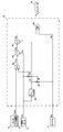
- FIG. 2 is a diagram showing a hydraulic drive device provided in the electric hydraulic work machine according to the first embodiment.
- the hydraulic drive device is composed of an electric motor 1, a variable capacity main hydraulic pump (hereinafter referred to as a main pump) 2 driven by the electric motor 1, a fixed capacity pilot pump 30, and pressure oil discharged from the main pump 2.
- a plurality of driven actuators such as a boom cylinder 3a, an arm cylinder 3b, a swivel motor 3c, a bucket cylinder 3d (see FIG. 1), a swing cylinder 3e (same as above), a traveling motor 3f, 3g (same as above), and a blade cylinder 3h (same as above).
- the pressure oil supply path 5 for guiding the pressure oil discharged from the main pump 2 to the plurality of actuators 3a, 3b, 3c, 3d, 3e, 3f, 3g, 3h, and the downstream of the pressure oil supply path 5. It is provided with a control valve block 4 which is connected to and guides the pressure oil discharged from the main pump 2.
- actuator 3a, 3b, 3c, 3d, 3f, 3g, 3h will be abbreviated as “actuator 3a, 3b, 3c ".
- the control valve block 4 is a control valve device that distributes and supplies the pressure oil discharged from the main pump 2 to a plurality of actuators 3a, 3b, 3c ..., And a plurality of actuators are contained in the control valve block 4.
- a plurality of directional switching valves 6a, 6b, 6c ... For controlling 3a, 3b, 3c ... And a plurality of directional switching valves 6a, 6b, 6c ... On the downstream side of each meter-in opening, respectively.
- a plurality of located pressure compensating valves 7a, 7b, 7c ... Are arranged. For the plurality of pressure compensating valves 7a, 7b, 7c ..., the direction switching valves 6a, 6b, 6c ...
- shuttle valves 9a, 9b, 9c Connected to the load pressure detection ports of a plurality of directional switching valves 6a, 6b, 6c ... Are arranged.
- the shuttle valves 9a, 9b, 9c ... Are connected in a tournament format, and the maximum load pressure is detected in the uppermost shuttle valve 9a and output to the oil passage 8.
- the unload valve 15 has pressure receiving portions 15a and 15d and springs 15b for urging the spool of the unload valve 15 in the closing direction, and a pressure receiving portion 15c for urging the spool in the opening direction.
- the output pressure Pgr (target LS differential pressure) of the prime mover rotation speed detection valve 13 described later is guided to the pressure receiving part 15d, and the pressure oil is supplied to the pressure receiving part 15c.
- the pressure of the path 5 (discharge pressure of the main pump 2) Pps is guided, and the unload valve is derived from the spring constant of the spring 15b and the output pressure (target LS differential pressure Pgr) of the prime mover rotation speed detection valve 13 guided to the pressure receiving portion 15d.
- An unload differential pressure of 15 is set.
- the variable displacement type main pump 2 has a regulator 12, in which the pressure (discharge pressure of the main pump 2) Pps of the pressure oil supply path 5 is guided to the regulator 12, and the absorption torque of the main pump 2 is set by the spring 12e. It is provided with a torque control piston 12d that controls the capacity (tilt angle) of the main pump 2 so as not to exceed a predetermined value.
- FIG. 3 is a diagram showing the absorption torque characteristics of the main pump 2 controlled by the torque control piston 12d.
- the horizontal axis represents the discharge pressure Pps of the main pump 2
- the vertical axis represents the capacity q (tilt angle) of the main pump 2.
- the capacity q of the main pump 2 is equal to the maximum capacity qmax determined by the specifications of the main pump 2, and when the discharge pressure Pps rises above Ppq1, the discharge pressure Pps rises.
- the capacity q gradually becomes smaller than the maximum capacity qmax, and when the discharge pressure Pps reaches Ppq2, the capacity q becomes equal to qmin.
- the discharge pressure is from Ppq1 to Ppq2, the absorption torque of the main pump 2 is maintained at a predetermined value set by the spring 12e.
- Ppq2 is the maximum pressure determined by the set pressure of the main relief valve 14.
- the regulator 12 also guides the flow rate control piston 12c that controls the discharge flow rate of the main pump 2 and the constant pilot pressure Pi0 generated by the pilot relief valve 32 described later to the flow rate control piston 12c, or the flow rate control piston 12c. It is equipped with an LS valve 12b that switches whether the pressure is discharged to the tank.
- the output pressure Pls of the differential pressure reducing valve 11 is guided to the LS valve 12b in the direction of switching to guide the constant pilot pressure Pi0 to the flow control piston 12c so that the pressure oil of the flow control piston 12c is discharged to the tank.
- the output pressure Pgr (target LS differential pressure) of the prime mover rotation rate detection valve 13 is guided in the direction of switching to.
- the pressure Pps of the pressure oil supply path 5 discharge pressure of the main pump 2 rotates from the maximum load pressure Plmax of the actuator driven by the pressure oil discharged from the main pump 202.
- the capacity of the main pump 2 is controlled so that the output pressure Pgr (target LS differential pressure) of the number detection valve 13 is increased.
- the prime mover rotation speed detection valve 13 is provided in the pilot pressure supply path 31a of the pilot pump 30, and detects the rotation speed of the electric motor 1 from the discharge flow rate of the pilot pump 30.
- the prime mover rotation speed detection valve 13 targets the flow rate detection valve 13a connected between the pressure oil supply path 31a and the pilot pressure oil supply path 31b of the pilot pump 30 and the front-rear differential pressure of the flow rate detection valve 13a. It has a differential pressure reducing valve 13b that outputs as a pressure Pgr.
- a pilot relief valve 32 that keeps the pressure of the pilot pressure supply path 31b constant and forms a pilot oil pressure source in the pilot pressure supply path 31b, and a pilot pressure supply A switching valve 100 for switching whether or not to supply the pressure of the path 31b to a plurality of pilot valves (pressure reducing valves) (not shown) for operating the plurality of direction switching valves 6a, 6b, 6c ... Is provided. ..
- the plurality of pilot valves are incorporated in a plurality of operating lever devices including the boom cylinder 3a, the arm cylinder 3b, the bucket cylinder 3d, and the operating lever devices 124A and 124B (see FIG.
- the switching valve 100 is provided with the above-mentioned gate lock lever 24 for switching whether or not to permit the operation of the operating lever of the operating lever device, and the switching valve 100 is an operator in the cab 108 (see FIG. 1).
- the gate lock lever 24 By operating the gate lock lever 24, the pressure of the pilot pressure supply path 31b is supplied to a plurality of pilot valves (not shown) as the pilot primary pressure, or the pilot primary pressure supplied to the pilot valves is supplied to the tank. It is switched whether to discharge.
- the main pump 2 is a hydraulic pump driven by an electric motor 1
- the electric hydraulic work machine is an electric hydraulic work machine that drives the main pump 2 to perform work.
- the electric hydraulic work machine includes a controller 50 that controls the rotation speed of the electric motor 1 based on the target rotation speed of the electric motor 1.
- the controller 50 is detected by the capacity of the main pump 2 (hydraulic pump) and the pressure sensor 41.
- the target power that the main pump 2 is about to consume is calculated based on the discharge pressure of the main pump 2 and the preset target rotation speed of the motor 1, and the motor is set so that the target power is within the range of the maximum allowable power. Limit the target rotation speed of 1. The details will be described below.
- the hydraulic drive system includes an inverter 60 for controlling the rotation speed of the electric motor 1 and a battery 70 connected to the inverter 60 so as to supply DC power via a DC power supply path 65.
- the hydraulic drive device includes an AC / DC converter 90 connected to the DC power supply path 65 and a connector 91 connected to the AC / DC converter 90, and a commercial power supply 92 is connected to the connector 91.
- the AC power supplied from the commercial power supply 92 is configured to be able to supply the DC power to the inverter 60 via the connector 91 and the AC / DC converter 90.
- the hydraulic drive system further includes a target rotation speed indicating dial (target rotation speed indicating device) 51 for instructing the target rotation speed of the electric motor 1 and a maximum allowable power setting device 81 for setting the maximum allowable power that can be consumed by the electric motor 1.
- a target rotation speed indicating dial (target rotation speed indicating device) 51 for instructing the target rotation speed of the electric motor 1
- a maximum allowable power setting device 81 for setting the maximum allowable power that can be consumed by the electric motor 1.
- a built-in monitor 80 and a pressure sensor 41 connected to the pressure oil supply path 5 and detecting the pressure of the pressure oil supply path 5 as the discharge pressure Pps of the main pump 2 are provided, and the output of the pressure sensor 41 and the target rotation speed instruction are indicated.
- the output of the dial 51 and the output of the maximum allowable power setting device 81 are guided to the controller 50, respectively.
- the controller 50 outputs the target rotation speed of the electric motor 1 to the inverter 60 as a command rotation speed.
- the maximum allowable power setting device 81 built in the monitor 80 stores a plurality of maximum allowable powers corresponding to the power sources for supplying power to the electric motor 1 according to the type of the power source, and the stored maximum allowable powers of the stored maximum allowable powers. It is configured to select the one corresponding to the battery 70 and the commercial power source 92, which are the power sources for supplying electric power to the electric motor 1, and set the maximum permissible power. For example, a current value is stored as the maximum allowable power.
- FIG. 4 is a functional block diagram of the controller 50 according to the first embodiment.
- the controller 50 has a table 50a, a multiplication unit 50b, a multiplication unit 50c, a minimum value selection unit 50d, a division unit 50e, a division unit 50f, and a minimum value selection unit 50g as its processing functions.
- the table 50a has the same characteristics as the absorption torque characteristics (see FIG. 3) of the main pump 2 controlled by the torque control piston 12d of the regulator 12 described above.
- the discharge pressure Pps of the main pump 2 which is the output from the pressure sensor 41 is guided to the table 50a, and the capacity q of the main pump 2 is calculated by referring to the discharge pressure Pps of the main pump 2 on the table 50a.
- the main pump 2 may be of a fixed capacity type.
- a table having a constant capacity qmax as shown in FIG. 7 is used as in the hydraulic pump 21 in the second embodiment described later. It may be prepared and the capacity may be calculated from the discharge pressure of the main pump at that time. Further, a constant capacity qmax may be stored in the memory of the controller 50, and the capacity qmax may be used.
- the target rotation speed Nac which is an input from the target rotation speed instruction dial 51, is guided to the multiplication unit 50b together with the capacitance q calculated in the table 50a, and the target flow rate Qac is calculated.
- the maximum permissible power Pwmax which is the output from the maximum permissible power setting device 81 built in the monitor 80 and the target power Pwac calculated by the multiplication unit 50c are guided to the minimum value selection unit 50d, and the post-limit power Pwreg is generated. It is calculated.
- the post-limit flow rate Qreg and the capacity q calculated in the table 50a are guided to the division unit 50f, and the post-limit rotation speed Nreg is calculated.
- the target rotation speed Nac which is the input from the post-limit rotation speed Nreg and the target rotation speed instruction dial 51, is input to the minimum value selection unit 50g, and the smaller value of the post-limit rotation speed Nreg and the target rotation speed Nac is the command rotation speed. It is selected as Nd and output to the inverter 60.
- the controller 50 has the first target rotation speed (after limitation) of the motor 1 based on the post-limit power Pwreg, which is the smaller power of the maximum permissible power Pwmax set by the target power Pwac and the maximum permissible power setting device 81.
- Rotation speed) Nreg is calculated, and the smaller target rotation speed of the target rotation speed Nac of the motor 1 instructed by the first target rotation speed Nreg and the target rotation speed indicating device (target rotation speed indicating dial) 51 is used as the second target rotation speed. It is selected as the target rotation speed (command target rotation speed) Nd, and the rotation speed of the electric motor 1 is controlled based on the second target rotation speed Nd.
- the pressure oil discharged from the fixed-capacity pilot pump 30 is supplied to the pilot pressure supply path 31a, and the prime mover rotation speed detection valve 13 outputs the target LS differential pressure Pgr according to the discharge flow rate of the pilot pump 30.
- the pilot primary pressure Ppi0 generated by the pilot relief valve 32 is supplied to each pilot valve of the plurality of operating lever devices including the operating lever devices 124A and 124B via the switching valve 100 which is switched and operated by the gate lock lever. Will be done.
- the flow rate control of the main pump 2 by the LS valve 12b and the flow rate control piston 12c is a general load sensing control, and therefore the details thereof will be omitted.
- the DC power supplied from the battery 70, the DC power converted from the AC power by the AC / DC converter 90 from the commercial power supply 92 via the connector 91, or both DC powers pass through the DC power supply path 65. It is supplied to the inverter 60 that drives the electric motor 1 via the system.
- the maximum allowable power Pwmax preset in advance is input to the controller 50 from the maximum allowable power setting device 81 built in the monitor 80.
- the output from the pressure sensor 41 is input to the controller 50 as the pump discharge pressure Pps, and the output from the target rotation speed indicator dial 51 is input to the controller 50 as the target rotation speed Nac.
- the processing in the controller 50 will be described below for each case.
- the rotation speed Nreg and the target rotation speed Nac are input to the minimum value selection unit 50g, and the minimum value is selected.
- the rotation speed Nreg and the target rotation speed Nac are input to the minimum value selection unit 50g.
- Nreg which is a value smaller than the target rotation speed Nac, is selected as the command rotation speed Nd and is output from the controller 50 to the inverter 60.
- the controller 50 has a target power Pwac that the main pump 2 is about to consume based on the capacity q of the main pump 2, the discharge pressure Pps of the main pump 2 detected by the pressure sensor 41, and the target rotation speed Nac of the electric motor 1. Is calculated, the command rotation speed Nd is output to the inverter 60 so that the target power Pwac is within the range of the maximum allowable power Pwmax, and the target rotation speed Nac of the motor 1 is limited. It is definitely limited to power Pwmax or less. This prevents the voltage of the battery 70 that supplies electric power to the electric motor 1 from dropping abnormally and the breaker of the commercial power supply 92 from operating at the cutoff position during the operation of the electric hydraulic work machine, and suddenly the front work machine 104. Stopping can be reliably prevented.
- the target rotation speed Nac of the motor 1 is limited so that the power consumption of the motor 1 does not exceed the maximum allowable power Pwmax, so that the voltage of the battery 70 It surely prevents the abnormal decrease of the front work machine 104 and the sudden stop of the front work machine 104 caused by the breaker operation of the commercial power supply 92, and minimizes the decrease of the work efficiency without lowering the operation speed of the front work machine 104 more than necessary. Can be suppressed to.
- the electric power consumed by the electric motor of an electric hydraulic work machine is substantially equal to the electric power consumed by the hydraulic pump driven by the electric motor and is proportional to "discharge pressure" x "discharge flow rate". Since the discharge flow rate is proportional to the rotation speed of the electric motor, it is common practice for the operator to set the indicated value of the target rotation speed indicating dial to be small when it is desired to reduce the power consumption of the electric motor. However, it is necessary for the operator to learn by himself while performing the actual work how small the indicated value of the target rotation speed indicator dial can be set to prevent the electric hydraulic work machine from stopping during operation. , It was a cause of impairing the comfort of the operator due to its annoyance.
- the controller 50 uses the capacity q of the main pump 2, the discharge pressure Pps of the main pump 2 detected by the pressure sensor 41, and the target rotation speed of the electric motor 1 indicated by the target rotation speed indicating dial 51.
- the target power Pwac that the main pump 2 is about to consume is calculated based on Nac. Therefore, the operator of the electric hydraulic work machine does not need to operate the target rotation speed indicating dial 51 of the electric motor 1 to limit the rotation speed of the electric motor 1, and can save the trouble of operation.
- the rotation speed of the electric motor 1 is not unnecessarily limited and the operating speed of the front work machine 104 is not lowered, so that the work efficiency of the electric hydraulic work machine is lowered. It can be minimized.
- the maximum permissible power setting device 81 selects a power source corresponding to the battery 70 and the commercial power source 92, which are power sources for supplying electric power to the electric motor 1, from a plurality of maximum permissible powers stored in advance, and sets the maximum permissible power. Since it is configured, even an operator who is unfamiliar with the handling of an electric hydraulic work machine can easily set the maximum allowable power.
- the controller 50 sets the same characteristics as the absorption torque characteristics of the main pump 2 (see FIG. 4) in the table 50a, and refers to the discharge pressure Pps of the main pump 2 detected by the pressure sensor 1 in the table 50a to refer to the main pump 2 Since the capacity q of the main pump 2 is calculated, the absorption torque of the main pump 2 is calculated accurately, and it is ensured that the voltage of the battery 70 that supplies power to the electric motor 1 drops abnormally and that the breaker of the commercial power supply 92 operates at the cutoff position. Can be prevented.
- the controller 50 does not output the post-restricted rotation speed (first target rotation speed) Nreg of the motor 1 calculated based on the post-restricted power Pwreg as the commanded rotation speed Nd to the inverter 60 as it is, but instead uses the post-restricted rotation speed Nreg.
- the smaller target rotation speed (second target rotation speed) of the target rotation speed Nac indicated by the target rotation speed instruction dial 51 is output to the inverter 60 as the command rotation speed Nd to control the rotation speed of the electric motor 1.
- FIG. 5 is a diagram showing a flood control drive device provided in the electric hydraulic work machine of the second embodiment.
- the hydraulic drive device is a hydraulic pump in which the hydraulic pump does not control the flow rate by load sensing, and includes two hydraulic pumps (first and second hydraulic pumps) as the hydraulic pumps.
- Point, hydraulic pump One of the two hydraulic pumps is a split flow type, and correspondingly, three pressure sensors are provided as pressure sensors to detect the discharge pressure of the hydraulic pump.
- the control valve block does not perform diversion control. It is a control valve device equipped with an open center type direction switching valve, and the regulator of the hydraulic pump controls all torque (when there are multiple hydraulic pumps, the total absorption torque of multiple hydraulic pumps does not exceed the predetermined value. It is different from the first embodiment in that it is configured to perform torque control) for controlling the capacity of one hydraulic pump.
- the hydraulic drive system of the present embodiment includes a variable capacity type main hydraulic pump (first hydraulic pump) 20 which is a split flow type hydraulic pump driven by an electric motor 1, and a fixed capacity type hydraulic pump. It is provided with a main hydraulic pump (second hydraulic pump) 21 which is a pump.
- the split flow type main pump 20 has two discharge ports 20a and 20b for discharging pressure oil extruded from a common pressure feeding mechanism including a swash plate, a piston, etc., and the pressure discharged from the discharge ports 20a and 20b. Oil is supplied to each directional control valve.
- the main pump 20 may be a hydraulic pump having one discharge port. Further, the main pump 20 may be two or more hydraulic pumps having one discharge port.
- the hydraulic drive device of the present embodiment also includes a pressure oil supply path 5a for guiding the pressure oil discharged from one discharge port 20a of the main pump 20 to the plurality of actuators 3a, 3d, 3g, and the main pump 20.
- the pressure oil supply path 5b for guiding the pressure oil discharged from the other discharge port 20b to the plurality of actuators 3b, 3f and the pressure oil discharged from the main pump 21 are guided to the plurality of actuators 3c, 33, 3h. It is provided with a pressure oil supply passage 5c for the purpose and a control valve block 40 connected to the downstream of the pressure oil supply passages 5a, 5b, 5c and to which the pressure oil discharged from the main pumps 20 and 21 is guided.
- the plurality of actuators 3a, 3b, 3c, 3d, 3e, 3f, 3g, and 3h are boom cylinders, arm cylinders, swivel motors, bucket cylinders, swing cylinders, and traveling, respectively, as described in the first embodiment. Motors and blade cylinders.
- the control valve block 40 is a control valve device that distributes and supplies the pressure oil discharged from the main pumps 20 and 21 to a plurality of actuators 3a, 3b, 3c, 3d, 3e, 3f, 3g, and 3h.
- the block 40 there are a plurality of direction switching valves 16a, 16b, 16c, 16d, 16e, 16f, 16g, 16h for controlling a plurality of actuators 3a, 3b, 3c, 3d, 3e, 3f, 3g, 3h.
- the pressure oil of the pressure oil supply passages 5a, 5b, 5c is tanked.
- the main relief valves 14a, 14b, 14c to be discharged to the above are arranged, and between the pressure oil supply passages 5a, 5b, 5c and the plurality of direction switching valves 16a, 16b, 16c, 16d, 16e, 16f, 16g, 16h.
- the variable displacement type main pump 20 has a regulator 22, and the regulator 22 has a pressure of the pressure oil supply paths 5a and 5b (discharge pressures of the two discharge ports 20a and 20b of the main pump 20) and a pressure oil supply path 5c.
- Each pressure oil is guided, and the torque that controls the capacity (tilt angle) of the main pump 20 so that the total of the absorption torque of the main pump 20 and the absorption torque of the main pump 21 does not exceed the predetermined value set by the spring 22e. It is equipped with control pistons 22f, 22g, and 22h.
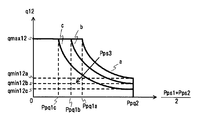
- FIG. 6 is a diagram showing the absorption torque characteristics of the main pump 20 controlled by the torque control pistons 22f, 22g, 22h.
- the horizontal axis is the average discharge pressure (Pps1 + Pps2) / 2 of the main pump 20, and the vertical axis is the capacity q12 (tilt angle) of the main pump 20.
- Pps1 and Pps2 are the discharge pressures of the two discharge ports 20a and 20b of the main pump 20
- Pps3 is the discharge pressure of the main pump 21.
- the average discharge pressure (Pps1 + Pps2) / 2 of the main pump 20 increases from Ppq1a to Ppq1c, similarly to the absorption torque characteristic of the regulator 12 in the first embodiment shown in FIG. Until then, it is equal to the maximum capacity qmax12 determined by the specifications of the main pump 2, and when the average discharge pressure (Pps1 + Pps2) / 2 rises above Ppq1a to Ppq1c, the average discharge pressure (Pps1 + Pps2) / 2 rises.
- the capacity q12 gradually becomes smaller than the maximum capacity qmax12, and when the average discharge pressure (Pps1 + Pps2) / 2 reaches Ppq2, the capacity q12 becomes equal to qmin12a to qmin12c. While the average discharge pressure (Pps1 + Pps2) / 2 is from Ppq1a to Ppq1c to Ppq2, the absorption torque of the main pump 20 is maintained at a predetermined value set by the spring 22e. Ppq2 is the maximum pressure determined by the set pressure of the main relief valves 14a and 14b.
- the characteristics between Ppq1a to Ppq1c to Ppq2 vary depending on the magnitude of the discharge pressure Pps3 of the main pump 21.
- the characteristics are on the curve a
- the characteristics are on the curve a.
- the characteristics are on the curve b.
- the fixed capacity type pilot pump 30 is directly connected to the pilot pressure supply path 31b, and the pilot pressure supply path 31b is provided with a pilot relief valve 32 and a switching valve 100 as in the first embodiment.
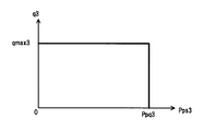
- FIG. 7 is a diagram showing the absorption torque characteristics of the fixed capacity type main pump 21.
- the horizontal axis is the discharge pressure Pps3 of the main pump 21, and the vertical axis is the capacity q3 (tilt angle) of the main pump 21. Since the main pump 21 is a fixed capacity type, the capacity is constant at qmax3 regardless of the value of the discharge pressure Pps3 of the main pump 21.
- Ppq3 is the maximum pressure determined by the set pressure of the main relief valve 14c.
- the hydraulic drive device includes a controller 55 that outputs the target rotation speed of the electric motor 1 to the inverter 60 as a command rotation speed, and is connected to the pressure oil supply passages 5a and 5b, and is connected to the main pump 20. It includes pressure sensors 41a and 41b that detect the discharge pressures Pps1 and Pps2 of the two discharge ports 20a and 20b, and a pressure sensor 41c that is connected to the pressure oil supply path 5c and detects the discharge pressure Pps3 of the main pump 21. ..
- the output of the pressure sensors 41a, 41b, 41c, the output of the target rotation speed indicator dial 51, and the output of the maximum allowable power setting device 81 are guided to the controller 55, respectively.
- FIG. 8 is a functional block diagram of the controller 55 in the second embodiment.
- the controller 55 has, as its processing functions, an addition unit 55a, a gain 55b, a table 55c, a gain 55d, a division unit 55e, a division unit 55f, an addition unit 55g, a table 55h, a multiplication unit 55i, a multiplication unit 55j, and a minimum. It has a value selection unit 55k, a gain 55l, a division unit 50m, a division unit 55n, and a minimum value selection unit 55o.
- the discharge pressure (Pps1 + Pps2) / 2 is calculated.
- the average discharge pressure (Pps1 + Pps2) / 2 of the main pump 20 is guided to the table 55c.
- the table 55c has the same characteristics as the absorption torque characteristics (FIG. 6) of the main pump 20 controlled by the torque control pistons 22f, 22g, 22h of the regulator 22 described above.
- the average discharge pressure (Pps1 + Pps2) / 2 of the main pump 20 and the discharge pressure Pps3 of the main pump 21 are guided to the table 55c, and the average discharge pressure (Pps1 + Pps2) / 2 of the main pump 20 and the discharge pressure of the main pump 21
- the capacity q12 of the main pump 20 is calculated with reference to Pps3 in Table 55c.
- the capacity q12 of the main pump 20 calculated in the table 55c is doubled by the gain 55d.
- the target rotation speed Nac input from the target rotation speed instruction dial 51 is guided to the division unit 55e together with the capacity q12 * 2 calculated by the gain 55d, and the target flow rate Q12ac of the main pump 20 is calculated.
- the target flow rate Q12ac is the total discharge flow rate of the two discharge ports 20a and 20b of the main pump 20.
- the average discharge pressure (Pps1 + Pps2) / 2 of the main pump 20 calculated by the target flow rate Q12ac and the gain 55b is guided to the multiplication / division unit 55f, and the target power Pw12ac of the main pump 20 is calculated.
- the table 55h has the same characteristics as the absorption torque characteristics (see FIG. 7) of the fixed capacity type main pump 21 described above.
- the discharge pressure Pps3 of the main pump 21, which is the output from the pressure sensor 41c, is guided to the table 55h, and the capacity q3 of the main pump 21 is calculated by referring to the discharge pressure Pps3 of the main pump 21 to the table 55h.
- the table 55h outputs a constant value qmax3 as the capacitance q3 regardless of the value of the discharge pressure Pps3.
- a constant capacity qmax3 may be stored in the memory of the controller 55 and the capacity qmax3 may be used.
- the target rotation speed Nac input from the target rotation speed instruction dial 51 is guided to the multiplication unit 55i together with the capacity q3 calculated in the table 55h, and the target flow rate Q3ac of the main pump 21 is calculated.
- the target flow rate Q3ac and the discharge pressure Pps3 of the main pump 21, which is the output from the pressure sensor 41c, are guided to the multiplication unit 55j, and the target power Pw3ac of the main pump 21 is calculated.
- the target power Pw12ac calculated by the multiplication unit 55f and the target power Pw3ac calculated by the multiplication unit 55j are added by the addition unit 55g, and the total target power Pw123ac is calculated.
- the maximum permissible power Pwmax which is the output from the maximum permissible power setting device 81 built in the monitor 80, and the target power Pw123ac calculated by the addition unit 55g are guided to the minimum value selection unit 55k, and the post-limit power Pwreg is calculated.
- the post-limit power Pwreg which is the output of the minimum value selection unit 55k, is led to a gain of 55l, and the post-limit power Pwreg is multiplied by Pw12ac / Pw123ac to calculate the post-limit power Pw12reg that can be used by the main pump 20.
- Pw12ac / Pw123ac is the variable capacity type main pump 20 calculated by the multiplication unit 55f with respect to the total target power Pw123ac of the variable capacity type main pump 20 and the fixed capacity type main pump 21 calculated by the addition unit 55g. It represents the ratio of the target power Pw12ac, in other words, the power that can be consumed by the variable capacity type main pump 20 among the power limited to the maximum allowable power Pwmax.
- the average discharge pressure (Pps1 + Pps2) / 2 of the main pump 20 calculated by the post-limit power Pw12reg and the gain 55b is guided to the dividing unit 50m, and the post-limit flow rate Q12reg is calculated.
- the capacitance q12 * 2 calculated by the post-limit flow rate Q12reg and the gain 55d is guided to the division unit 55n, and the post-limit rotation speed Nreg is calculated.
- the target rotation speed Nac which is the input from the post-limit rotation speed Nreg and the target rotation speed instruction dial 51, is input to the minimum value selection unit 55o, and the smaller value of the post-limit rotation speed Nreg and the target rotation speed Nac is the command rotation speed. It is selected as Nd and output to the inverter 60.
- the hydraulic drive device includes a plurality of hydraulic pumps including two main pumps 20, 21 (first and second hydraulic pumps), and two main pumps 20, 21 as pressure sensors.
- the controller 55 includes two main pumps 20, 21 (first and second hydraulic pumps), including a plurality of pressure sensors including first pressure sensors 41a and 41b and second pressure sensors 41c for detecting the respective discharge pressures of the above. , The discharge pressures of the two main pumps 20, 21 detected by the first pressure sensors 41a, 41b and the second pressure sensor 41c, and the target rotation speed of the electric motor 1, the two main pumps 20, 21 Calculate the target power that (first and second hydraulic pumps) is about to consume.
- the main pump 20 (first hydraulic pump) is a variable capacity type
- the main pump 21 (second hydraulic pump) is a fixed capacity type
- the main pump 20 (first hydraulic pump) discharges the main pump 20.
- the pressure and the discharge pressure of the main pump 21 (second hydraulic pump) are guided respectively, and the capacity of the main pump 20 is controlled so that the total of the absorption torque of the main pump 20 and the absorption torque of the main pump 21 does not exceed a predetermined value.
- the regulator 22 provided with the first torque control pistons 22f and 22g and the second torque control piston 22h is provided, and the table 55c of the controller 55 has the first torque control pistons 22f and 22g and the absorption torque characteristics of the main pump 20 as absorption torque characteristics.
- the absorption torque characteristic of the main pump 20 controlled by the second torque control piston 22h is set.
- the corresponding directional control valve is switched and the pressure oil is supplied to the corresponding actuator.
- the direction switching valve is switched by the stroke according to the operation amount of the operation lever, and the main pumps 20 and 21 driven by the electric motor 1 are the rotation speed of the electric motor 1 and the torque control pistons 22f, 22g and 22h of the regulator 22.
- the flow rate according to the absorption torque control is discharged, and the actuator is driven at a speed according to the operation amount of the operating lever.
- the DC power supplied from the battery 70, the DC power converted from the AC power by the AC / DC converter 90 from the commercial power supply 92 via the connector 91, or both DC powers pass through the DC power supply path 65. It is supplied to the inverter 60 that drives the electric motor 1 via the system.
- the maximum allowable power Pwmax preset in advance is input to the controller 50 from the maximum allowable power setting device 81 built in the monitor 80.
- the output from the pressure sensors 41a, 41b, 41c is input to the controller 55 as the pump discharge pressures Pps1, Pps2, Pps3, and the output from the target rotation speed indicator dial 51 is input to the controller 55 as the target rotation speed Nac.
- the processing in the controller 55 will be described below for each case.
- Pw12reg / (Pps1 + Pps2) / 2 is calculated.
- the rotation speed Nreg and the target rotation speed Nac are input to the minimum value selection unit 55o, and the minimum value is selected.
- the rotation speed Nreg and the target rotation speed Nac are input to the minimum value selection unit 55o.
- Nreg which is a value smaller than the target rotation speed Nac, is selected as the command rotation speed Nd and is output from the controller 55 to the inverter 60.
- the controller 55 is based on the capacities q12 and q3 of the main pumps 20 and 21, the discharge pressures Pps1 and Pps2 of the main pumps 20 and 21 detected by the pressure sensors 41a, 41b and 41c, and the target rotation speed Nac of the motor 1.
- the target power Pw123ac that the main pumps 20 and 21 are about to consume is calculated, the command rotation speed Nd is output to the inverter 60 so that the target power Pw123ac is within the range of the maximum allowable power Pwmax, and the target rotation speed of the motor 1 is achieved. Since Nac is limited, the power consumed by the motor 1 is surely limited to the maximum allowable power Pwmax or less.
- the power consumed by the motor 1 is surely limited to the maximum allowable power Pwmax or less. Be restricted. This prevents the voltage of the battery 70 that supplies electric power to the electric motor 1 from dropping abnormally and the breaker of the commercial power supply 92 from operating at the cutoff position during the operation of the electric hydraulic work machine, and suddenly the front work machine 104. Stopping can be reliably prevented.
- the hydraulic drive device includes a plurality of hydraulic pumps including two main pumps 20, 21 (first and second hydraulic pumps) as hydraulic pumps, and discharge pressures of the two main pumps 20, 21 as pressure sensors, respectively.
- the controller 55 includes a plurality of pressure sensors including the first pressure sensors 41a and 41b and the second pressure sensor 41c for detecting Pps1 and Pps2, and the controller 55 has the capacities of the two main pumps 20 and 21 (first and second hydraulic pumps). Two based on q12, q3, the discharge pressures Pps1 and Pps2 of the two main pumps 20 and 21 detected by the first pressure sensors 41a and 41b and the second pressure sensor 41c, and the target rotation speed Nac of the electric motor 1. Calculate the target power Pw123ac that the main pumps 20 and 21 (first and second hydraulic pumps) are about to consume.
- the target power Pw123ac that the plurality of hydraulic pumps (two main pumps 20 and 21) are about to consume can be obtained. It is possible to limit the target rotation speed Nac of the electric motor 1 so that the target power Pw123ac is within the range of the maximum allowable power Pwmax.
- the main pump 20 is a variable capacity type
- the main pump 21 is a fixed capacity type
- the regulator 22 of the main pump 20 (first hydraulic pump) is the discharge pressure of the main pump 20 and the main pump 21 (second hydraulic pump).
- a torque control piston (first torque control piston) 22f that controls the capacity of the main pump 20 so that the total of the absorption torque of the main pump 20 and the absorption torque of the main pump 21 does not exceed a predetermined value.
- the table 55c of the controller 55 sets the same absorption torque characteristics as the absorption torque characteristics of the main pump 20, and the table 55h Sets the same absorption torque characteristics as the absorption torque characteristics of the main pump 21, so the controller 55 calculates the target power Pw123ac that the two main pumps 20 and 21 are about to consume, and the target power Pw123ac is the maximum allowable.
- the target rotation speed Nac of the electric motor 1 can be limited so as to be within the range of the power Pwmax.
Landscapes
- Engineering & Computer Science (AREA)
- General Engineering & Computer Science (AREA)
- Mining & Mineral Resources (AREA)
- Civil Engineering (AREA)
- Structural Engineering (AREA)
- Fluid Mechanics (AREA)
- Physics & Mathematics (AREA)
- Mechanical Engineering (AREA)
- Computer Hardware Design (AREA)
- Chemical & Material Sciences (AREA)
- Analytical Chemistry (AREA)
- Fluid-Pressure Circuits (AREA)
- Control Of Positive-Displacement Pumps (AREA)
- Operation Control Of Excavators (AREA)
Priority Applications (6)
| Application Number | Priority Date | Filing Date | Title |
|---|---|---|---|
| PCT/JP2019/037330 WO2021059337A1 (ja) | 2019-09-24 | 2019-09-24 | 電動式油圧作業機械 |
| KR1020217040942A KR102715461B1 (ko) | 2019-09-24 | 2019-09-24 | 전동식 유압 작업 기계 |
| US17/595,712 US12416135B2 (en) | 2019-09-24 | 2019-09-24 | Electrically driven hydraulic work machine |
| CN201980097557.2A CN113994092B (zh) | 2019-09-24 | 2019-09-24 | 电动式液压作业机械 |
| JP2021548006A JP7261894B2 (ja) | 2019-09-24 | 2019-09-24 | 電動式油圧作業機械 |
| EP19946733.3A EP4036408B1 (en) | 2019-09-24 | 2019-09-24 | Electric hydraulic working machine |
Applications Claiming Priority (1)
| Application Number | Priority Date | Filing Date | Title |
|---|---|---|---|
| PCT/JP2019/037330 WO2021059337A1 (ja) | 2019-09-24 | 2019-09-24 | 電動式油圧作業機械 |
Publications (1)
| Publication Number | Publication Date |
|---|---|
| WO2021059337A1 true WO2021059337A1 (ja) | 2021-04-01 |
Family
ID=75165200
Family Applications (1)
| Application Number | Title | Priority Date | Filing Date |
|---|---|---|---|
| PCT/JP2019/037330 Ceased WO2021059337A1 (ja) | 2019-09-24 | 2019-09-24 | 電動式油圧作業機械 |
Country Status (6)
| Country | Link |
|---|---|
| US (1) | US12416135B2 (https=) |
| EP (1) | EP4036408B1 (https=) |
| JP (1) | JP7261894B2 (https=) |
| KR (1) | KR102715461B1 (https=) |
| CN (1) | CN113994092B (https=) |
| WO (1) | WO2021059337A1 (https=) |
Cited By (1)
| Publication number | Priority date | Publication date | Assignee | Title |
|---|---|---|---|---|
| JP2022155176A (ja) * | 2021-03-30 | 2022-10-13 | 日立建機株式会社 | 電動式建設機械 |
Families Citing this family (7)
| Publication number | Priority date | Publication date | Assignee | Title |
|---|---|---|---|---|
| JP6955524B2 (ja) * | 2019-03-26 | 2021-10-27 | 株式会社日立建機ティエラ | バッテリ式作業機械 |
| DE102020112660A1 (de) * | 2020-05-11 | 2021-11-11 | MOOG Gesellschaft mit beschränkter Haftung | Verfahren zum Bestimmen eines momentanen Verschleißzustandes einer hydrostatischen Maschine |
| US12280382B2 (en) * | 2021-06-24 | 2025-04-22 | Elgin Separation Solutions Industrials, Llc | Electronically controlled hydraulic decanter centrifuge |
| JP7710390B2 (ja) * | 2022-02-28 | 2025-07-18 | ヤンマーホールディングス株式会社 | 作業機械 |
| CN114434448B (zh) * | 2022-03-25 | 2024-04-30 | 江苏徐工工程机械研究院有限公司 | 破拆机器人的工作臂控制方法及控制系统 |
| JP7757010B2 (ja) * | 2022-08-10 | 2025-10-21 | 株式会社クボタ | 作業車両及び作業車両の制御方法 |
| EP4735698A1 (en) * | 2023-11-02 | 2026-05-06 | Doosan Bobcat North America, Inc. | Systems and methods for control of excavators and other power machines |
Citations (6)
| Publication number | Priority date | Publication date | Assignee | Title |
|---|---|---|---|---|
| JP2003155760A (ja) * | 2001-11-21 | 2003-05-30 | Kobelco Contstruction Machinery Ltd | 作業機械のアクチュエータ駆動装置 |
| JP2009084838A (ja) | 2007-09-28 | 2009-04-23 | Hitachi Constr Mach Co Ltd | バッテリ駆動建設機械 |
| WO2010082636A1 (ja) * | 2009-01-16 | 2010-07-22 | 住友重機械工業株式会社 | ハイブリッド式作業機械及びその制御方法 |
| WO2013164928A1 (ja) * | 2012-05-01 | 2013-11-07 | 日立建機株式会社 | ハイブリッド式作業機械 |
| WO2014084213A1 (ja) * | 2012-11-27 | 2014-06-05 | 日立建機株式会社 | 電動式油圧作業機械の油圧駆動装置 |
| WO2018168887A1 (ja) * | 2017-03-13 | 2018-09-20 | 株式会社日立建機ティエラ | 電動式油圧作業機械の油圧駆動装置 |
Family Cites Families (11)
| Publication number | Priority date | Publication date | Assignee | Title |
|---|---|---|---|---|
| JPS605176B2 (ja) * | 1980-03-28 | 1985-02-08 | 三和化學株式会社 | 合成樹脂製緩衝材およびその製造法 |
| JP3444503B2 (ja) * | 1993-03-26 | 2003-09-08 | 株式会社小松製作所 | 油圧駆動機械の制御装置 |
| JP3580260B2 (ja) * | 2001-03-01 | 2004-10-20 | 日産自動車株式会社 | 車両の制御装置 |
| JP4188902B2 (ja) * | 2004-11-22 | 2008-12-03 | 日立建機株式会社 | 油圧建設機械の制御装置 |
| JP5064160B2 (ja) * | 2007-09-19 | 2012-10-31 | 株式会社小松製作所 | エンジンの制御装置 |
| JP5096401B2 (ja) * | 2009-03-31 | 2012-12-12 | 理研ビタミン株式会社 | 粉末状ブラウンルウの製造方法 |
| US9518593B2 (en) * | 2011-08-31 | 2016-12-13 | Hitachi Construction Machinery Co., Ltd. | Hydraulic drive system for construction machine |
| CN103890409A (zh) * | 2011-10-20 | 2014-06-25 | 日立建机株式会社 | 电动式液压作业机械的液压驱动装置 |
| WO2013132721A1 (ja) * | 2012-03-05 | 2013-09-12 | 日立建機株式会社 | 建設機械の油圧駆動装置 |
| JP5984165B2 (ja) * | 2012-11-07 | 2016-09-06 | 日立建機株式会社 | 作業機械の油圧制御装置 |
| WO2020049668A1 (ja) | 2018-09-05 | 2020-03-12 | 株式会社日立建機ティエラ | 電動式油圧作業機械の油圧駆動装置 |
-
2019
- 2019-09-24 JP JP2021548006A patent/JP7261894B2/ja active Active
- 2019-09-24 KR KR1020217040942A patent/KR102715461B1/ko active Active
- 2019-09-24 WO PCT/JP2019/037330 patent/WO2021059337A1/ja not_active Ceased
- 2019-09-24 CN CN201980097557.2A patent/CN113994092B/zh active Active
- 2019-09-24 EP EP19946733.3A patent/EP4036408B1/en active Active
- 2019-09-24 US US17/595,712 patent/US12416135B2/en active Active
Patent Citations (6)
| Publication number | Priority date | Publication date | Assignee | Title |
|---|---|---|---|---|
| JP2003155760A (ja) * | 2001-11-21 | 2003-05-30 | Kobelco Contstruction Machinery Ltd | 作業機械のアクチュエータ駆動装置 |
| JP2009084838A (ja) | 2007-09-28 | 2009-04-23 | Hitachi Constr Mach Co Ltd | バッテリ駆動建設機械 |
| WO2010082636A1 (ja) * | 2009-01-16 | 2010-07-22 | 住友重機械工業株式会社 | ハイブリッド式作業機械及びその制御方法 |
| WO2013164928A1 (ja) * | 2012-05-01 | 2013-11-07 | 日立建機株式会社 | ハイブリッド式作業機械 |
| WO2014084213A1 (ja) * | 2012-11-27 | 2014-06-05 | 日立建機株式会社 | 電動式油圧作業機械の油圧駆動装置 |
| WO2018168887A1 (ja) * | 2017-03-13 | 2018-09-20 | 株式会社日立建機ティエラ | 電動式油圧作業機械の油圧駆動装置 |
Non-Patent Citations (1)
| Title |
|---|
| See also references of EP4036408A4 |
Cited By (2)
| Publication number | Priority date | Publication date | Assignee | Title |
|---|---|---|---|---|
| JP2022155176A (ja) * | 2021-03-30 | 2022-10-13 | 日立建機株式会社 | 電動式建設機械 |
| JP7609684B2 (ja) | 2021-03-30 | 2025-01-07 | 日立建機株式会社 | 電動式建設機械 |
Also Published As
| Publication number | Publication date |
|---|---|
| US12416135B2 (en) | 2025-09-16 |
| US20220259821A1 (en) | 2022-08-18 |
| EP4036408A4 (en) | 2023-05-31 |
| EP4036408B1 (en) | 2024-08-14 |
| CN113994092A (zh) | 2022-01-28 |
| KR20220009430A (ko) | 2022-01-24 |
| JP7261894B2 (ja) | 2023-04-20 |
| EP4036408A1 (en) | 2022-08-03 |
| CN113994092B (zh) | 2024-06-04 |
| JPWO2021059337A1 (https=) | 2021-04-01 |
| KR102715461B1 (ko) | 2024-10-11 |
Similar Documents
| Publication | Publication Date | Title |
|---|---|---|
| JP7261894B2 (ja) | 電動式油圧作業機械 | |
| JP7058783B2 (ja) | 電動式油圧作業機械の油圧駆動装置 | |
| US10655647B2 (en) | Hydraulic drive system for construction machine | |
| US10280592B2 (en) | Hydraulic drive system for electrically-operated hydraulic work machine | |
| US9951797B2 (en) | Work machine | |
| CN102741484B (zh) | 液压系统的泵控制装置 | |
| JP3985756B2 (ja) | 建設機械の油圧制御回路 | |
| US9026297B2 (en) | Control system for hybrid construction machine | |
| US20120093624A1 (en) | Work machine and control method for work machines | |
| US11753800B2 (en) | Hydraulic drive system for construction machine | |
| US10107310B2 (en) | Hydraulic drive system | |
| US11346081B2 (en) | Construction machine | |
| US20240263424A1 (en) | Excavator | |
| JP6759135B2 (ja) | 建設機械の油圧制御装置 |
Legal Events
| Date | Code | Title | Description |
|---|---|---|---|
| 121 | Ep: the epo has been informed by wipo that ep was designated in this application |
Ref document number: 19946733 Country of ref document: EP Kind code of ref document: A1 |
|
| ENP | Entry into the national phase |
Ref document number: 2021548006 Country of ref document: JP Kind code of ref document: A |
|
| ENP | Entry into the national phase |
Ref document number: 20217040942 Country of ref document: KR Kind code of ref document: A |
|
| NENP | Non-entry into the national phase |
Ref country code: DE |
|
| ENP | Entry into the national phase |
Ref document number: 2019946733 Country of ref document: EP Effective date: 20220425 |
|
| WWG | Wipo information: grant in national office |
Ref document number: 17595712 Country of ref document: US |