WO2021054076A1 - 超音波診断装置および超音波診断装置の制御方法 - Google Patents
超音波診断装置および超音波診断装置の制御方法 Download PDFInfo
- Publication number
- WO2021054076A1 WO2021054076A1 PCT/JP2020/032409 JP2020032409W WO2021054076A1 WO 2021054076 A1 WO2021054076 A1 WO 2021054076A1 JP 2020032409 W JP2020032409 W JP 2020032409W WO 2021054076 A1 WO2021054076 A1 WO 2021054076A1
- Authority
- WO
- WIPO (PCT)
- Prior art keywords
- ultrasonic
- maximum diameter
- ultrasonic probe
- unit
- feature amount
- Prior art date
- Legal status (The legal status is an assumption and is not a legal conclusion. Google has not performed a legal analysis and makes no representation as to the accuracy of the status listed.)
- Ceased
Links
Images


Classifications
-
- A—HUMAN NECESSITIES
- A61—MEDICAL OR VETERINARY SCIENCE; HYGIENE
- A61B—DIAGNOSIS; SURGERY; IDENTIFICATION
- A61B8/00—Diagnosis using ultrasonic, sonic or infrasonic waves
- A61B8/08—Clinical applications
- A61B8/0833—Clinical applications involving detecting or locating foreign bodies or organic structures
- A61B8/085—Clinical applications involving detecting or locating foreign bodies or organic structures for locating body or organic structures, e.g. tumours, calculi, blood vessels, nodules
-
- A—HUMAN NECESSITIES
- A61—MEDICAL OR VETERINARY SCIENCE; HYGIENE
- A61B—DIAGNOSIS; SURGERY; IDENTIFICATION
- A61B8/00—Diagnosis using ultrasonic, sonic or infrasonic waves
- A61B8/08—Clinical applications
-
- A—HUMAN NECESSITIES
- A61—MEDICAL OR VETERINARY SCIENCE; HYGIENE
- A61B—DIAGNOSIS; SURGERY; IDENTIFICATION
- A61B8/00—Diagnosis using ultrasonic, sonic or infrasonic waves
- A61B8/13—Tomography
- A61B8/14—Echo-tomography
-
- A—HUMAN NECESSITIES
- A61—MEDICAL OR VETERINARY SCIENCE; HYGIENE
- A61B—DIAGNOSIS; SURGERY; IDENTIFICATION
- A61B8/00—Diagnosis using ultrasonic, sonic or infrasonic waves
- A61B8/42—Details of probe positioning or probe attachment to the patient
- A61B8/4245—Details of probe positioning or probe attachment to the patient involving determining the position of the probe, e.g. with respect to an external reference frame or to the patient
- A61B8/4254—Details of probe positioning or probe attachment to the patient involving determining the position of the probe, e.g. with respect to an external reference frame or to the patient using sensors mounted on the probe
-
- A—HUMAN NECESSITIES
- A61—MEDICAL OR VETERINARY SCIENCE; HYGIENE
- A61B—DIAGNOSIS; SURGERY; IDENTIFICATION
- A61B8/00—Diagnosis using ultrasonic, sonic or infrasonic waves
- A61B8/52—Devices using data or image processing specially adapted for diagnosis using ultrasonic, sonic or infrasonic waves
- A61B8/5215—Devices using data or image processing specially adapted for diagnosis using ultrasonic, sonic or infrasonic waves involving processing of medical diagnostic data
- A61B8/5223—Devices using data or image processing specially adapted for diagnosis using ultrasonic, sonic or infrasonic waves involving processing of medical diagnostic data for extracting a diagnostic or physiological parameter from medical diagnostic data
-
- A—HUMAN NECESSITIES
- A61—MEDICAL OR VETERINARY SCIENCE; HYGIENE
- A61B—DIAGNOSIS; SURGERY; IDENTIFICATION
- A61B8/00—Diagnosis using ultrasonic, sonic or infrasonic waves
- A61B8/54—Control of the diagnostic device
-
- A—HUMAN NECESSITIES
- A61—MEDICAL OR VETERINARY SCIENCE; HYGIENE
- A61B—DIAGNOSIS; SURGERY; IDENTIFICATION
- A61B8/00—Diagnosis using ultrasonic, sonic or infrasonic waves
- A61B8/46—Ultrasonic, sonic or infrasonic diagnostic devices with special arrangements for interfacing with the operator or the patient
- A61B8/467—Ultrasonic, sonic or infrasonic diagnostic devices with special arrangements for interfacing with the operator or the patient characterised by special input means
Definitions
- the present invention relates to an ultrasonic diagnostic apparatus for measuring the amount of urine in the bladder of a subject and a control method for the ultrasonic diagnostic apparatus.
- an ultrasonic diagnostic apparatus has been known as a device for obtaining an image of the inside of a subject.
- An ultrasonic diagnostic apparatus generally includes an ultrasonic probe provided with an oscillator array in which a plurality of ultrasonic oscillators are arranged. With this ultrasonic probe in contact with the body surface of the subject, an ultrasonic beam is transmitted from the transducer array toward the inside of the subject, and the ultrasonic echo from the subject is received by the transducer array to obtain an ultrasonic beam. The electrical signal corresponding to the ultrasonic echo is acquired. Further, the ultrasonic diagnostic apparatus electrically processes the obtained electric signal to generate an ultrasonic image of the site of the subject.
- the bladder of the subject is observed and the amount of urine in the observed bladder is measured.
- the volume of urine in the bladder of the subject is approximately equal to the volume of the bladder of the subject, so the volume of the bladder of the subject is measured as the volume of urine.
- the volume of the bladder of the subject can be calculated, for example, by regarding the bladder as an ellipse and using the maximum diameter in the vertical direction, the maximum diameter in the horizontal direction, and the maximum diameter in the depth direction of the bladder.
- the user can move the bladder probe to obtain a tomographic image of the bladder that maximizes the vertical and horizontal diameters of the bladder. , It was necessary to observe the tomographic images of the bladder that maximizes the diameter in the depth direction of the bladder and manually measure the diameter of the bladder.
- the ultrasonic diagnostic apparatus disclosed in Patent Document 1 has been developed.
- a tilt angle sensor for measuring the tilt angle of the ultrasonic probe is included in the ultrasonic probe, and the ultrasonic probe is in contact with the body surface of the subject.
- the diameter in the depth direction of the bladder is calculated based on the tilt angle of the ultrasonic probe measured while tilting and the position of the deepest part of the bladder of the subject calculated from the ultrasonic image at this time.
- the vertical and horizontal diameters of the bladder are also calculated, and urine in the bladder is calculated based on the obtained three-direction diameters. The amount is calculated.
- the user uses an ultrasonic image of the bladder in order to calculate the maximum diameter in the depth direction of the bladder.
- the ultrasound probe needs to be tilted until it is no longer visible.
- the ultrasonic diagnostic apparatus of Patent Document 1 since it is necessary for the user to determine the position on the subject with which the ultrasonic probe is in contact, for example, the position where the ultrasonic probe is deviated from directly above the center of the bladder of the subject. Was sometimes placed in.
- the ultrasonic probe when the ultrasonic probe is placed at a position deviated from directly above the center of the bladder of the subject, the user can use the case where the ultrasonic probe is placed directly above the center of the bladder of the subject. It is necessary to tilt the ultrasonic probe more than the body surface of the subject, and the ultrasonic probe moves away from the body surface of the subject, and the ultrasonic probe slips on the body surface of the subject and the position of the ultrasonic probe slips. There is a problem that the accuracy of measuring the amount of urine in the bladder of the subject is lowered.
- the present invention has been made to solve such a conventional problem, and controls an ultrasonic diagnostic apparatus and an ultrasonic diagnostic apparatus capable of measuring the amount of urine in the bladder of a subject with high accuracy.
- the purpose is to provide a method.
- the ultrasonic diagnostic apparatus uses an ultrasonic probe for contacting a subject and scanning an ultrasonic beam on the subject, and an inclination angle of the ultrasonic probe.
- the tilt angle sensor to detect, the image acquisition unit that acquires multiple frames of ultrasonic images corresponding to multiple different tomographic surfaces in the subject using an ultrasonic probe, and the bladder from each of the multiple frames of ultrasonic images.
- a bladder extraction unit that extracts a region, a feature amount calculation unit that calculates a feature amount related to the bladder region extracted by the bladder extraction unit in each of multiple frames of ultrasonic images, and an ultrasonic probe along the body surface of the subject.
- the first maximum diameter and the second maximum diameter of the bladder region in the scanning cross section by the ultrasonic probe based on the feature amount calculated by the feature amount calculation unit from the ultrasonic image acquired by the image acquisition unit while sliding.
- a target slide along the body surface of the subject of the ultrasonic probe so that the scanning cross section of the first measuring unit and the ultrasonic probe shows the first maximum diameter and the second maximum diameter. Detected by the operation assist unit that assists the slide operation to the position, the ultrasonic image acquired by the image acquisition unit and the tilt angle sensor while changing the tilt angle of the ultrasonic probe at the target slide position assisted by the operation assist unit.
- the second measuring unit that measures the third maximum diameter of the bladder region in the cross section orthogonal to the scanning cross section by the ultrasonic probe based on the tilt angle of the ultrasonic probe, and the second measuring unit that measures the first measuring unit. It is characterized by including a bladder volume calculation unit that calculates the volume of the bladder based on the 1 maximum diameter, the 2nd maximum diameter, and the 3rd maximum diameter measured by the 2nd measurement unit.
- the feature amount calculation unit can calculate the first diameter and the second diameter of the bladder region in two directions in the cross section scanned by the ultrasonic probe as the feature amount.
- the feature amount calculation unit can also calculate the product of the first diameter and the second diameter of the bladder region in the two directions in the cross section scanned by the ultrasonic probe as the feature amount.
- the feature amount calculation unit can also calculate the area of the bladder region in the scanning cross section by the ultrasonic probe as the feature amount.
- the first measuring unit may measure the first diameter and the second diameter in two directions in the scanning cross section where the feature amount calculated by the feature amount calculating unit is the maximum as the first maximum diameter and the second maximum diameter. it can. At this time, the first measurement unit can calculate the maximum feature amount based on the feature amount calculated by the feature amount calculation unit.
- the ultrasonic diagnostic apparatus includes a monitor that displays an ultrasonic image, and the operation assist unit can assist the user in sliding the ultrasonic probe to the target slide position by displaying the assist information on the monitor. it can. At this time, the operation assist unit can display the ratio or difference between the feature amount calculated by the feature amount calculation unit and the maximum feature amount measured by the first measurement unit on the monitor as assist information.
- the operation assist unit uses ultrasonic waves when the ratio of the feature amount to the maximum feature amount exceeds the ratio threshold value or when the difference between the maximum feature amount and the feature amount becomes less than or equal to the difference threshold value. It is possible to display on the monitor that the scanning cross section by the probe is a cross section showing the first maximum diameter and the second maximum diameter. In addition, the operation assist unit can further display an ultrasonic image representing a scanning cross section indicating the first maximum diameter and the second maximum diameter on the monitor as assist information.
- the ultrasonic diagnostic apparatus is provided with a speaker, and the operation assist unit can assist the user in the slide operation of the ultrasonic probe to the target slide position by emitting a sound from the speaker. Further, the ultrasonic diagnostic apparatus includes a lamp, and the operation assist unit can assist the user in the slide operation of the ultrasonic probe to the target slide position by emitting light from the lamp.
- the feature amount calculated by the feature amount calculation unit in a state where the tilt angle of the ultrasonic probe detected by the tilt angle sensor becomes zero is arranged at the target slide position and tilted.
- the tilt angle of the ultrasonic probe detected by the angle sensor is zero and the ratio is less than or equal to the feature amount calculated by the feature amount calculation unit, the ultrasonic wave is sent to the user again. It is possible to assist the slide operation of the probe to the target slide position.
- the second measuring unit tilts the ultrasonic probe only on one side of the scanning cross section, so that the ultrasonic image acquired by the image acquisition unit and the tilt angle of the ultrasonic probe are changed while changing the tilt angle of the ultrasonic probe. Based on this, the third maximum diameter can be measured.
- the ultrasonic diagnostic apparatus can include a device control unit that controls the tilt angle sensor so that the tilt angle sensor operates only when the second measuring unit measures the third maximum diameter.
- the ultrasonic diagnostic apparatus includes at least a bladder extraction unit, a feature amount calculation unit, a first measurement unit, an operation assist unit, a second measurement unit, and a bladder volume calculation unit, and is connected to an ultrasonic probe by wireless communication.
- the ultrasonic probe includes at least a tilt angle sensor and a probe control unit that controls the tilt angle sensor so that the tilt angle sensor operates only when the second measuring unit measures the third maximum diameter. You can also prepare.
- the first measuring unit can measure the first maximum diameter and the second maximum diameter based on the feature amount calculated by the feature amount calculating unit within a predetermined scanning time.
- the ultrasonic diagnostic apparatus is provided with an input device for the user to perform an input operation, and an instruction to remeasure the first maximum diameter and the second maximum diameter is input by the user via the input device.
- the first measuring unit can measure the first maximum diameter and the second maximum diameter again based on the feature amount calculated by the feature amount calculating unit in the predetermined scanning time.
- the scanning time can be adjusted based on the input operation of the user via the input device.
- the first measurement unit is based on the feature amounts in the ultrasonic images of the frames other than the continuous frames. 1 maximum diameter and 2nd maximum diameter can be measured.
- the control method of the ultrasonic diagnostic apparatus is to scan an ultrasonic beam on a subject with an ultrasonic probe in contact with the subject, detect the tilt angle of the ultrasonic probe, and detect the tilt angle of the ultrasonic probe.
- the feature amount related to the bladder region extracted by the bladder extraction unit is calculated, and the ultrasonic probe is used based on the feature amount calculated from the ultrasonic image acquired while sliding the ultrasonic probe along the body surface of the subject.
- the first maximum diameter and the second maximum diameter of the bladder region in two directions in the scanning cross section are measured, and the scanning cross section by the ultrasonic probe is super-sized to show the first maximum diameter and the second maximum diameter.
- An ultrasonic image acquired while changing the tilt angle of the ultrasonic probe at the assisted target slide position by assisting the slide operation of the ultrasonic probe to the target slide position along the body surface of the subject, and the detected ultrasonic image.
- the third maximum diameter of the bladder region in the cross section orthogonal to the scanning cross section by the ultrasonic probe is measured based on the tilt angle of the ultrasonic probe, and the measured first maximum diameter and second maximum diameter are measured. It is characterized in that the volume of the bladder is calculated based on the third maximum diameter.
- the ultrasonic diagnostic apparatus includes a tilt angle sensor that detects the tilt angle of the ultrasonic probe, a bladder extraction unit that extracts a bladder region from each of a plurality of frames of ultrasonic images, and a plurality of frames of ultrasonic waves.
- An ultrasonic image acquired by the image acquisition unit while sliding the ultrasonic probe along the body surface of the subject and the feature amount calculation unit that calculates the feature amount related to the bladder region extracted by the bladder extraction unit in each of the images. Scanning with an ultrasonic probe based on the feature amount calculated by the feature amount calculation unit from the first measuring unit that measures the first maximum diameter and the second maximum diameter of the bladder region in two directions in the cross section, and scanning with the ultrasonic probe.
- An operation assist unit that assists the user in sliding the ultrasonic probe to the target slide position along the body surface of the subject so that the cross section shows the first maximum diameter and the second maximum diameter.
- the second measuring unit that measures the third maximum diameter of the bladder region in the cross section orthogonal to the scanning cross section by the probe, and the first maximum diameter, the second maximum diameter, and the second measuring unit measured by the first measuring unit. Since the bladder volume calculation unit that calculates the bladder volume based on the measured third maximum diameter is provided, the urine volume in the bladder of the subject can be measured with high accuracy.
- Embodiment 1 of this invention It is a block diagram which shows the structure of the ultrasonic diagnostic apparatus which concerns on Embodiment 1 of this invention. It is a block diagram which shows the internal structure of the transmission / reception circuit in Embodiment 1 of this invention. It is a block diagram which shows the internal structure of the image generation part in Embodiment 1 of this invention. It is a figure which shows typically the example of the ultrasonic image including the bladder region in Embodiment 1 of this invention. It is a figure which shows typically the example of the assist information displayed in Embodiment 1 of this invention. It is a figure which shows typically the example of other assist information displayed in Embodiment 1 of this invention.
- Embodiment 1 of this invention It is a figure which shows typically the ultrasonic probe which came in contact with the subject in Embodiment 1 of this invention, and the bladder of the subject located directly under the ultrasonic probe. It is a schematic diagram which shows how the ultrasonic probe is tilted in Embodiment 1 of this invention. It is a figure which shows typically the distance from the body surface of a subject measured in Embodiment 1 of this invention to the deepest part of the bladder region of a subject. It is a figure which shows typically the 3rd maximum diameter measured in Embodiment 1 of this invention. It is a figure which shows the example of an ellipsoid. It is a flowchart which shows the operation of the ultrasonic diagnostic apparatus which concerns on Embodiment 1 of this invention.
- the figure which shows typically the example which the ratio of the current area of the bladder to the maximum area of the bladder, and the ultrasonic image which shows the 1st maximum diameter and the 2nd maximum diameter are displayed as the assist information in Embodiment 1 of this invention.
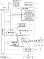
- FIG. 1 shows the configuration of the ultrasonic diagnostic apparatus 1 according to the first embodiment of the present invention.
- the ultrasonic diagnostic apparatus 1 includes an oscillator array 2, and a transmission / reception circuit 3, an image generation unit 4, a display control unit 6, and a monitor 7 are sequentially connected to the oscillator array 2.
- the image acquisition unit 5 is configured by the transmission / reception circuit 3 and the image generation unit 4.
- the oscillator array 2 and the transmission / reception circuit 3 are included in the ultrasonic probe 21.
- the bladder extraction unit 8 is connected to the image generation unit 4, and the feature amount calculation unit 9 and the first measurement unit 10 are connected to the bladder extraction unit 8. Further, the first measurement unit 10 is connected to the feature amount calculation unit 9.
- the operation assist unit 11 is connected to the feature amount calculation unit 9 and the first measurement unit 10, and the display control unit 6 is connected to the operation assist unit 11.
- the image memory 12 is connected to the image generation unit 4, and the operation assist unit 11 is connected to the image memory 12.
- the ultrasonic probe 21 includes a tilt angle sensor 13.
- the second measuring unit 14 is connected to the bladder extraction unit 8 and the tilt angle sensor 13.
- the bladder volume calculation unit 15 is connected to the first measurement unit 10 and the second measurement unit 14, and the display control unit 6 is connected to the bladder volume calculation unit 15.
- the device control unit 16 is connected to the volume calculation unit 15. Further, an input device 17 is connected to the device control unit 16.
- the oscillator array 2, the transmission / reception circuit 3, and the tilt angle sensor 13 are included in the ultrasonic probe 21.
- the processor 22 for the ultrasonic diagnostic apparatus 1 is configured. Further, it is assumed that the ultrasonic diagnostic apparatus 1 includes an apparatus main body (not shown) including a processor 22, and the apparatus main body and the ultrasonic probe 21 are connected to each other by wired communication.
- the oscillator array 2 of the ultrasonic probe 21 shown in FIG. 1 has a plurality of oscillators arranged one-dimensionally or two-dimensionally. Each of these oscillators transmits ultrasonic waves according to a drive signal supplied from the transmission / reception circuit 3, receives an ultrasonic echo from a subject, and outputs a signal based on the ultrasonic echo.
- Each transducer includes, for example, a piezoelectric ceramic represented by PZT (Lead Zirconate Titanate), a polymer piezoelectric element represented by PVDF (PolyVinylidene DiFluoride), and PMN-PT (PMN-PT).
- Electrodes at both ends of a piezoelectric material made of a piezoelectric single crystal or the like represented by Lead Magnesium Niobate-Lead Titanate (lead magnesiumidene fluoride-lead zirconate titanate).
- the transmission / reception circuit 3 transmits ultrasonic waves from the oscillator array 2 and generates a sound line signal based on the received signal acquired by the oscillator array 2 under the control of the device control unit 16.
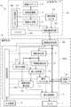
- the transmission / reception circuit 3 includes a pulsar 23 connected to the oscillator array 2, an amplification unit 24 connected in series from the oscillator array 2, an AD (Analog Digital) conversion unit 25, and a beam former.
- AD Analog Digital
- the pulsar 23 includes, for example, a plurality of pulse generators, and is transmitted from the plurality of oscillators of the oscillator array 2 based on a transmission delay pattern selected according to a control signal from the device control unit 16.
- Each drive signal is supplied to a plurality of oscillators by adjusting the delay amount so that the ultrasonic waves form an ultrasonic beam.
- a pulsed or continuous wave voltage is applied to the electrodes of the vibrator of the vibrator array 2
- the piezoelectric body expands and contracts, and pulsed or continuous wave ultrasonic waves are generated from each vibrator.
- An ultrasonic beam is formed from the combined waves of those ultrasonic waves.
- the transmitted ultrasonic beam is reflected by, for example, a target such as a site of a subject, and propagates toward the vibrator array 2 of the ultrasonic probe 21.
- the ultrasonic echo propagating toward the oscillator array 2 is expanded and contracted by each oscillator constituting the oscillator array 2 by receiving the propagating ultrasonic echo, and the received signal is an electric signal. Is generated, and these received signals are output to the amplification unit 24.
- the amplification unit 24 amplifies the signal input from each of the vibrators constituting the vibrator array 2, and transmits the amplified signal to the AD conversion unit 25.
- the AD conversion unit 25 converts the signal transmitted from the amplification unit 24 into digital reception data, and transmits these reception data to the beam former 26.
- the beam former 26 follows the sound velocity or sound velocity distribution set based on the reception delay pattern selected according to the control signal from the device control unit 16, and is used for each received data converted by the AD conversion unit 25, respectively. By giving a delay of and adding, so-called reception focus processing is performed. By this reception focus processing, each received data converted by the AD conversion unit 25 is phase-adjusted and added, and a sound line signal in which the focus of the ultrasonic echo is narrowed down is acquired.
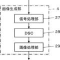
- the image generation unit 4 has a configuration in which a signal processing unit 27, a DSC (Digital Scan Converter) 28, and an image processing unit 29 are sequentially connected in series.
- the signal processing unit 27 corrects the attenuation due to the distance according to the depth of the reflection position of the ultrasonic wave to the sound line signal generated by the beam former 26 of the transmission / reception circuit 3, and then performs the envelope detection process.
- Generates a B-mode image signal which is tomographic image information about the tissue in the subject.
- the DSC 28 converts the B-mode image signal generated by the signal processing unit 27 into an image signal according to a normal television signal scanning method (raster conversion).
- the image processing unit 29 performs various necessary image processing such as gradation processing on the B mode image signal input from the DSC 28, and then displays the B mode image signal in the display control unit 6, the bladder extraction unit 8, and the second measurement. Output to unit 14.
- the B-mode image signal that has been image-processed by the image processing unit 29 is simply referred to as an ultrasonic image.
- the bladder extraction unit 8 extracts the bladder region BR from each of the plurality of frames of the ultrasonic image U1 generated by the image generation unit 4, as shown in FIG. 4, for example.
- the bladder extraction unit 8 is described in, for example, Krizhevsk et al .: ImageNet Classification with Deep Convolutional Neural Networks, Advances in Neural Information Processing Systems 25, pp.1106-1114 (2012). ) Can be used to extract the bladder region BR in the ultrasonic image U1.
- the bladder extraction unit 8 uses a graph cut (Y.Boykov and V.Kolmogorov, ”An experimental comparison of min-cut / max-flow algorithm for energy minimization in” as another method for extracting the bladder region BR.
- the feature amount calculation unit 9 calculates the feature amount related to the extracted bladder region BR in each of the plurality of frames of the ultrasonic image U1 in which the bladder region BR is extracted by the bladder extraction unit 8.
- the feature amount calculation unit 9 can calculate, for example, the diameter of the extracted bladder region BR in two directions, the product of the diameters in these two directions, the area of the bladder region BR, and the like as the feature amount.
- the diameters of the bladder region BR in the two directions are the first diameter F1 which is the maximum diameter of the bladder region BR and the bladder in the direction orthogonal to the direction along the first diameter F1. It refers to the second diameter F2, which is the maximum diameter of the region BR.
- the first measurement unit 10 is based on the feature amount calculated by the feature amount calculation unit 9 from the ultrasonic image U1 acquired by the image acquisition unit 5 while sliding the ultrasonic probe 21 along the body surface of the subject. Then, the first maximum diameter G1 and the second maximum diameter G2 in two directions orthogonal to each other in the bladder region BR in the scanning cross section by the ultrasonic probe 21 are measured. For example, the first measurement unit 10 is based on the feature amount calculated by the feature amount calculation unit 9 while the ultrasonic probe 21 is sliding along the body surface of the subject within a predetermined scanning time.
- the maximum feature amount is calculated, the ultrasonic image U1 of the frame showing the maximum feature amount is selected, and the first diameter F1 and the second diameter F2 in the two directions of the bladder region BR included in the ultrasonic image U1 are the first, respectively. It can be calculated as 1 maximum diameter G1 and 2 maximum diameter G2.
- sliding the ultrasonic probe 21 along the body surface of the subject means moving the ultrasonic probe 21 along a certain direction while keeping the ultrasonic probe 21 in contact with the body surface of the subject.
- the ultrasonic probe 21 is moved on the body surface of the subject while keeping the tilt angle of the ultrasonic probe 21 substantially constant, but also the movement of the ultrasonic probe 21 is temporarily interrupted. This includes tilting the ultrasonic probe 21 and tilting the ultrasonic probe 21 while moving the ultrasonic probe 21.
- the operation assist unit 11 moves to the target slide position along the body surface of the subject of the ultrasonic probe 21 so that the scanning cross section of the ultrasonic probe 21 is a cross section showing the first maximum diameter G1 and the second maximum diameter G2. Assists the user in the slide operation of.
- the operation assist unit 11 can display the assist information for assisting the user in the slide operation of the ultrasonic probe 21 on the monitor 7.
- the operation assist unit 11 is, for example, the current feature amount calculated by the feature amount calculation unit 9, the maximum feature amount calculated by the first measurement unit 10, and the current feature amount with respect to the maximum feature amount.
- the ratio can be displayed on the monitor 7 as assist information.
- the operation assist unit 11 has the current first diameter F1 and second diameter F2, first maximum diameter G1 and second maximum diameter G2, and first as assist information.
- the ratio R1 of the first diameter F1 to the maximum diameter G1 and the ratio R2 of the second diameter F2 to the second maximum diameter G2 can be displayed on the monitor 7.
- the monitor 7 currently has a frame display area AU1 and a measured value display area AN, and in the measured value display area AN, the current first diameter F1, second diameter F2, and first maximum diameter G1.
- the second maximum diameter G2, the ratio R1 of the first diameter F1 to the first maximum diameter G1, and the ratio R2 of the second diameter F2 to the second maximum diameter G2 are displayed as assist information. Further, the current ultrasonic image U1 acquired by the image acquisition unit 5 is displayed in the current frame display area AU1.
- the operation assist unit 11 sets a ratio threshold value such that the ratio of the current feature amount calculated by the feature amount calculation unit 9 to the maximum feature amount calculated by the first measurement unit 10 is, for example, 95 (%). When it exceeds, it can be displayed on the monitor 7 that the scanning cross section by the ultrasonic probe 21 is a cross section showing the first maximum diameter G1 and the second maximum diameter G2.
- the ratio R1 of the first diameter F1 to the first maximum diameter G1 exceeds the ratio threshold value
- the ratio R2 of the second diameter F2 to the second maximum diameter G2 exceeds the ratio threshold value.
- a message M1 indicating that the scanning cross section by the ultrasonic probe 21 is a cross section showing the first maximum diameter G1 and the second maximum diameter G2 can be displayed on the monitor 7.
- the message M1 "This is a cross section showing the maximum diameter. Please tilt the probe.” Is displayed on the monitor 7. The user slides the ultrasonic probe 21 while confirming such assist information, and arranges the ultrasonic probe 21 at an appropriate slide position.
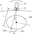
- the ultrasonic probe 21 is arranged at the assisted target slide position, and the contact position of the ultrasonic probe 21 with respect to the subject S is kept constant in the arrangement direction of the vibrator array 2.
- the arrangement direction of the vibrator array 2 and the direction in which the rotation axis R extends are the directions perpendicular to the paper surface in FIG. 7, and the ultrasonic probe 21 rotates about the rotation axis R from the ultrasonic probe 21.
- the scanning cross section PS1 extending in the subject S rotates about the rotation axis R.
- the inclination angle A of the ultrasonic probe 21 means that the normal direction of the vibrator array 2 at the center of the vibrator array 2 of the ultrasonic probe 21 is perpendicular to the body surface of the subject S. It represents the angle at which the ultrasonic probe 21 is tilted from the state. That is, the inclination angle A is zero in the ultrasonic probe 21 in a state where the normal direction of the vibrator array 2 faces the direction perpendicular to the body surface of the subject S, and from that state, the ultrasonic probe 21 It is assumed that the more inclined the value is, the larger the value is. In the examples shown in FIGS.
- the tilt angle A is the scanning cross section PS1 oriented in a direction perpendicular to the body surface of the subject S and the scanning cross section PS2 in a state where the ultrasonic probe 21 is tilted. It is expressed as the rotation angle between.
- the tilt angle sensor 13 measures the tilt angle A of the ultrasonic probe 21.
- the tilt angle sensor 13 includes a so-called gyro sensor, an acceleration sensor, a magnetic sensor, or the like, and ultrasonically obtains an electric signal obtained from the gyro sensor, the acceleration sensor, the magnetic sensor, or the like by using a well-known calculation method or the like. Converted to the tilt angle A of the probe 21.
- the tilt angle sensor 13 can assign a code corresponding to the tilt direction of the ultrasonic probe 21 to the tilt angle A in order to distinguish the tilt direction of the ultrasonic probe 21. For example, when the ultrasonic probe 21 is tilted to one side of the scanning cross section PS1 with reference to the scanning cross section PS1 by the ultrasonic probe 21 in a state where the tilt angle A is zero, the direction in which the ultrasonic probe 21 is tilted is determined. As a positive direction, a positive sign is given to the detected tilt angle A, and when the ultrasonic probe 21 is tilted to the other side of the scanning cross section PS1, the tilting direction of the ultrasonic probe 21 is defined as a negative direction. , A negative sign can be added to the detected tilt angle A.
- the second measurement unit 14 uses the ultrasonic image U1 acquired by the image acquisition unit 5 and the tilt angle sensor 13 while changing the tilt angle A of the ultrasonic probe 21 at the target slide position assisted by the operation assist unit 11. Based on the detected tilt angle A of the ultrasonic probe 21, the third maximum diameter H of the bladder region BR in the cross section orthogonal to the scanning cross section PS1 by the ultrasonic probe 21 in the state where the tilt angle A is zero is measured.
- the third maximum diameter H of the bladder region BR is the maximum of the bladder region BR in a direction orthogonal to both the direction along the first maximum diameter G1 and the direction along the second maximum diameter G2 of the bladder region BR. Refers to the diameter.
- the second measurement unit 14 analyzes the ultrasonic image U1 acquired by the image acquisition unit 5 to obtain the body of the subject S.
- the distance L to the deepest part of the bladder region BR extracted by the bladder extraction unit 8 from the table is measured, and the calculated distance L and the inclination angle A of the ultrasonic probe 21 detected by the inclination angle sensor 13 are used.
- W L ⁇
- the second measurement unit 14 sets the shortest distance in the direction along the scanning line from the upper end of the ultrasonic image U1 to the deepest part of the bladder region BR, for example, from the body surface of the subject S to the deepest part of the bladder region BR. It can be measured as the distance L to the part.
- the second measurement unit 14 continues to calculate the length W in the third direction while the inclination angle A of the ultrasonic probe 21 is changing, and for example, as shown in FIG. 10, the scanning cross section PS1 is used as a reference.
- the maximum third-direction length W1 when the ultrasonic probe 21 is tilted in the positive direction and the maximum third-direction length W2 when the ultrasonic probe 21 is tilted in the negative direction are obtained.
- the third maximum diameter H can be calculated by calculating and calculating the sum of the calculated lengths W1 and W2 in the third direction.
- the distance L2 from the body surface of the subject S to the deepest part of the bladder region BR measured when the ultrasonic probe 21 is tilted in the negative direction and the tilt angle A2 of the ultrasonic probe 21 at that time are used.
- W2 L2 ⁇
- the second measurement unit 14 determines whether or not the tilting operation of the ultrasonic probe 21 by the user has been completed, and when it is determined that the tilting operation of the ultrasonic probe 21 has been completed, the length W1 in the third direction. , W2 is calculated, and the sum of these is calculated to calculate the third maximum diameter H.
- the second measuring unit 14 may perform the tilting operation as an operation of tilting the ultrasonic probe 21, when the user tilts the ultrasonic probe 21 in each of the positive and negative directions until the bladder region BR is not visualized on the ultrasonic image U1, the second measuring unit 14 may perform the tilting operation.
- the tilt angle A detected by the tilt angle sensor 13 changes in the order of zero, positive maximum tilt angle, zero, negative maximum tilt angle, and zero, or zero, negative maximum tilt angle, zero, positive maximum tilt.
- the tilting operation of the ultrasonic probe 21 by the user is completed.
- the user tilts the ultrasonic probe 21 in the positive direction with reference to the scanning cross section PS1, and the tilt angle A of the ultrasonic probe 21 when the bladder region BR is no longer visualized on the ultrasonic image U1 is set.
- This is called the maximum positive tilt angle
- the tilt angle A of the ultrasonic probe 21 when the user tilts the ultrasonic probe 21 in the negative direction and the bladder region BR is no longer visualized on the ultrasonic image U1 is negative. It will be called the maximum tilt angle.
- the bladder volume calculation unit 15 is based on the first maximum diameter G1 and the second maximum diameter G2 measured by the first measurement unit 10 and the third maximum diameter H measured by the second measurement unit 14.
- the volume of the bladder of the subject S is calculated as the amount of urine in the bladder of the subject S. Since the bladder generally has an ellipsoidal shape, the bladder volume calculation unit 15 calculates the volume of the bladder as the volume of the ellipsoid.
- the ellipsoid E has a shape symmetrical with respect to the XY plane, the YZ plane, and the XZ plane, and the maximum diameter of the ellipsoid E in the X direction is set in the LX and Y directions.
- the bladder volume calculation unit 15 calculates the volume of the bladder of the subject S by calculating (first maximum diameter G1) ⁇ (second maximum diameter G2) ⁇ (third maximum diameter H) ⁇ ⁇ / 6. can do.
- the image memory 12 stores the ultrasonic image U1 acquired by the image acquisition unit 5.
- the image memory 12 includes a flash memory, an HDD (Hard Disc Drive), an SSD (Solid State Drive), an FD (Flexible Disc), and an MO disk (Magneto-Optical disc). ), MT (Magnetic Tape), RAM (Random Access Memory), CD (Compact Disc), DVD (Digital Versatile Disc), SD card (Secure Digital card)
- a recording medium such as a digital card), a USB memory (Universal Serial Bus memory), a server, or the like can be used.
- the display control unit 6 Under the control of the device control unit 16, the display control unit 6 performs predetermined processing on the ultrasonic image U1 acquired by the image acquisition unit 5, the assist information by the operation assist unit 11, and displays them on the monitor 7. To do.
- the monitor 7 displays the ultrasonic image U1 acquired by the image acquisition unit 5, the assist information by the operation assist unit 11, and the like under the control of the display control unit 6, and for example, an LCD (Liquid Crystal Display: liquid crystal display). Display), organic EL display (Organic Electroluminescence Display) and other display devices are included.
- the input device 17 is for the user to perform an input operation, and can be configured to include a keyboard, a mouse, a trackball, a touch pad, a touch panel, and the like.
- the device control unit 16 controls each part of the ultrasonic diagnostic device 1 based on a control program or the like stored in advance.
- the processor 22 is composed of a CPU (Central Processing Unit) and a control program for causing the CPU to perform various processes, and is composed of an FPGA (Field Programmable Gate Array). Using DSP (Digital Signal Processor), ASIC (Application Specific Integrated Circuit), GPU (Graphics Processing Unit), and other ICs (Integrated Circuit) It may be configured, or it may be configured by combining them.
- the control unit 16 may be partially or wholly integrated into one CPU or the like.
- step S1 the ultrasonic image U1 is generated, and the generated ultrasonic image U1 is displayed on the monitor 7.
- the user contacts the ultrasonic probe 21 on the body surface of the subject S, and the subject S is transmitted from the plurality of vibrators of the vibrator array 2 according to the drive signal from the pulsar 23 of the transmission / reception circuit 3.
- An ultrasonic beam is transmitted to the inside, and a received signal is output to the amplification unit 24 of the transmission / reception circuit 3 from each vibrator that has received the ultrasonic echo from the subject S.
- the received signal is amplified by the amplification unit 24, AD-converted by the AD conversion unit 25, and then phase-adjusted and added by the beam former 26 to generate a sound line signal.
- This sound line signal becomes a B-mode image signal when the signal processing unit 27 performs envelope detection processing in the image generation unit 4, and is output to the display control unit 6 via the DSC 28 and the image processing unit 29.
- the ultrasonic image U1 is displayed on the monitor 7 under the control of the display control unit 6.
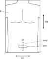
- the user has a horizontal direction D1 when facing the subject S from the front, a vertical direction D2 along the height direction of the subject S, a horizontal direction D1 and a vertical direction D2.
- the three directions of the depth direction (not shown) orthogonal to both of the above are regarded as any of the X direction, the Y direction, and the Z direction in the ellipsoid E
- the tomographic plane of the bladder along the lateral direction D1 of the subject S is defined.
- An ultrasonic probe 21 is placed at either the first contact position PP1 for observation or the second contact position PP2 for observing the tomographic surface of the bladder along the longitudinal direction D2 of the subject S, and an ultrasonic image is obtained.
- U1 is photographed, and the position of the ultrasonic probe 21 is adjusted so that the bladder region BR is visualized in the ultrasonic image U1.
- step S2 the device control unit 16 determines whether or not the measurement of the urine volume in the bladder of the subject S is started. For example, the device control unit 16 determines that the urine volume measurement in the bladder of the subject S has started when the user inputs an instruction to start the urine volume measurement via the input device 17. When the instruction to start the urine volume measurement is not input, it can be determined that the urine volume measurement in the bladder of the subject S has not been started. For example, if the user continues to adjust the position of the ultrasonic probe 21 and the user does not input an instruction to start urine volume measurement via the input device 17, the urine volume in the bladder of the subject S It is determined that the measurement is not started, the process returns to step S1, the ultrasonic image U1 is acquired, and then the process proceeds to step S2.
- the urine volume measurement in the bladder of the subject S is performed. Is determined to have started, and the process proceeds to step S3.
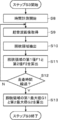
- step S3 the first measurement unit 10 has the first maximum diameter of the bladder region BR included in the ultrasonic image U1 based on the ultrasonic image U1 acquired by the image acquisition unit 5 during the predetermined scanning time. Acquire G1 and the second maximum diameter G2. The operation of the ultrasonic diagnostic apparatus 1 in step S3 will be described in detail with reference to the flowchart shown in FIG.
- step S8 the device control unit 16 starts measuring the time.
- the time measured in this way is used for determining whether or not a predetermined scanning time has elapsed, as will be described later.
- step S9 the image acquisition unit 5 acquires the ultrasonic image U1. At this time, the user captures the ultrasonic image U1 while sliding the ultrasonic probe 21.
- the bladder extraction unit 8 extracts the bladder region BR included in the ultrasonic image U1 acquired in step S9.
- the bladder extraction unit 8 is described in, for example, Krizhevsk et al .: ImageNet Classification with Deep Convolutional Neural Networks, Advances in Neural Information Processing Systems 25, pp.1106-1114 (2012). ) Can be used to extract the bladder region BR in the ultrasonic image U1.
- the bladder extraction unit 8 uses a graph cut (Y.Boykov and V.Kolmogorov, ”An experimental comparison of min-cut / max-flow algorithm for energy minimization in” as another method for extracting the bladder region BR.
- step S11 the feature amount calculation unit 9 calculates the feature amount related to the bladder region BR extracted in step S9.
- the feature amount calculation unit 9 calculates the first diameter F1 and the second diameter F2 of the bladder region BR as the feature amount.
- the feature amount calculation unit 9 first calculates the maximum diameter in the bladder region BR in the ultrasonic image U1 as the first diameter F1, and follows the first diameter F1.
- the maximum diameter of the bladder region BR in the direction orthogonal to the direction can be calculated as the second diameter F2.
- step S12 the device control unit 16 determines whether or not the predetermined scanning time has elapsed with reference to the elapsed time from the time when the time measurement is started in step S8. If it is determined that the predetermined scanning time has not elapsed, the process returns to step S9, the ultrasonic image U1 is acquired, the bladder region BR is extracted in step S10, and the first bladder region BR is determined in step S11. The diameter F1 and the second diameter F2 are calculated. In this way, the processes of steps S9 to S12 are repeated until the predetermined scanning time elapses. If it is determined in step S12 that the predetermined scanning time has elapsed, the time measurement by the device control unit 16 ends, and the process proceeds to step S13.
- the first measuring unit 10 has the first diameter F1 of the bladder region BR calculated for the ultrasonic image U1 of a plurality of frames by repeating steps S9 to S12 performed during the predetermined scanning time.
- a frame having both the maximum diameter F2 and the second diameter F2 is selected, and the first diameter F1 and the second diameter F2 in the ultrasonic image U1 of this frame are calculated as the first maximum diameter G1 and the second maximum diameter G2.
- step S4 the device control unit 16 displays on the monitor 7 a message M2 indicating that the predetermined scanning time has elapsed and prompting the scanning by the ultrasonic probe 21 again.
- the message M2 "Scanning time has elapsed. Please scan again.” Is displayed on the monitor 7. The user confirms this message M2 and slides the ultrasonic probe 21 again on the body surface of the subject S.
- step S5 the operation assist unit 11 slides the ultrasonic probe 21 to the target slide position so that the scanning cross section of the ultrasonic probe 21 has a cross section showing the first maximum diameter G1 and the second maximum diameter G2. To assist the user.
- the operation of the ultrasonic diagnostic apparatus 1 in step S5 will be described in detail with reference to the flowchart shown in FIG.
- step S14 the image acquisition unit 5 acquires the ultrasonic image U1.
- step S15 the bladder extraction unit 8 extracts the bladder region BR included in the ultrasonic image U1 acquired in step S14.
- the feature amount calculation unit 9 calculates the first diameter F1 and the second diameter F2 of the bladder region BR extracted in step S15 as the feature amount.
- step S17 the operation assist unit 11 sets the ratio R1 of the first diameter F1 calculated in step S16 to the ratio R1 of the first maximum diameter G1 calculated in step S3 to the second maximum diameter G2 calculated in step S3.
- the ratio R2 of the second diameter F2 calculated in S16 is calculated.
- the operation assist unit 11 includes the first diameter F1 and the second diameter F2 calculated in step S16, the first maximum diameter G1 calculated in step S3, and the assist information.
- the second maximum diameter G2 and the ratios R1 and R2 calculated in step S17 are displayed on the monitor 7 as assist information for assisting the user in the sliding operation of the ultrasonic probe 21.
- the user slides the ultrasonic probe 21 while checking the assist information displayed in this way, so that the ultrasonic image U1 corresponding to the scanning cross section showing the first maximum diameter G1 and the second maximum diameter G2
- the position of the ultrasonic probe 21 can be easily adjusted so that
- step S19 the operation assist unit 11 determines whether or not both the ratios R1 and R2 calculated in step S17 are larger than the predetermined ratio threshold value.
- the process returns to step S14.
- the ultrasonic image U1 is acquired in step S14, the bladder region BR is extracted in step S15, the first diameter F1 and the second diameter F2 of the bladder region BR are calculated in step S16, and the first maximum diameter G1 is calculated in step S17.
- step S18 The ratio R1 of the first diameter F1 and the ratio R2 of the second diameter F2 to the second maximum diameter G2 are calculated, and in step S18, the first diameter F1, the second diameter F2, the first maximum diameter G1, the second maximum diameter G2, The ratios R1 and R2 are displayed on the monitor 7, and the process proceeds to step S19. In this way, in step S19, the processes of steps S14 to S19 are repeated until it is determined that both the ratios R1 and R2 are larger than the predetermined ratio threshold value.
- step S19 If it is determined in step S19 that both the ratios R1 and R2 calculated in step S17 are larger than the predetermined ratio threshold value, the process proceeds to step S20.
- step S20 as shown in FIG. 6, the operation assist unit 11 moves the ultrasonic probe to the target slide position where the ultrasonic image U1 corresponding to the scanning cross section showing the first maximum diameter G1 and the second maximum diameter G2 is acquired.
- a message M1 indicating that 21 is arranged is displayed on the monitor 7.
- the message M1 "This is a cross section showing the maximum diameter. Please tilt the probe.” Is displayed on the monitor 7.
- step S5 the process of step S5 is completed.
- step S6 the second measurement unit 14 acquires the third maximum diameter H of the bladder region BR.
- the operation of the ultrasonic diagnostic apparatus 1 in step S6 will be described in detail with reference to the flowchart shown in FIG.
- the user tilts the ultrasonic probe 21 so as to change the tilt angle A of the ultrasonic probe 21 at the assisted target slide position by confirming the message M1 displayed on the monitor 7 in step S5. ..
- the user arranges the ultrasonic probe 21 at the assisted target slide position, and the oscillator array 2 keeps the contact position of the ultrasonic probe 21 with respect to the subject S constant.
- the ultrasonic probe 21 is tilted about the rotation axis R parallel to the arrangement direction of.
- the scanning cross section extending from the ultrasonic probe 21 into the subject S rotates about the rotation axis R.
- it is assumed that the ultrasonic probe 21 is tilted in each of the positive and negative directions until the bladder region BR is no longer visualized in the ultrasonic image U1.
- the image acquisition unit 5 acquires the ultrasonic image U1 in step S21.
- the bladder extraction unit 8 extracts the bladder region BR included in the ultrasonic image U1 acquired in step S21.
- the second measurement unit 14 analyzes the ultrasonic image U1 acquired in step S21 to extract the bladder region from the body surface of the subject S in step S22.
- the distance L to the deepest part of BR is measured.
- the second measurement unit 14 sets the shortest distance in the direction along the scanning line from the upper end of the ultrasonic image U1 to the deepest part of the bladder region BR from the body surface of the subject S to the deepest part of the bladder region BR. Can be measured as the distance L of.
- the tilt angle sensor 13 detects the tilt angle A of the ultrasonic probe 21.
- the tilt angle sensor 13 can assign a reference numeral corresponding to the tilting direction of the ultrasonic probe 21 to the tilt angle A in order to distinguish the tilting direction of the ultrasonic probe 21. For example, when the ultrasonic probe 21 is tilted in the positive direction with reference to the scanning cross section PS1 in which the tilt angle A is zero, a positive sign is given to the detected tilt angle A and the tilt angle A is in the negative direction. When the ultrasonic probe 21 is tilted, the detected tilt angle A can be given a negative sign.
- step S25 the second measuring unit 14 calculates the length W of the bladder region BR in the third direction as shown in FIG.
- the second measurement unit 14 determines the distance L from the body surface of the subject S calculated in step S23 to the deepest part of the bladder region BR and the inclination angle A of the ultrasonic probe 21 detected in step S24.
- W L ⁇
- step S26 the second measurement unit 14 determines whether or not the tilting operation of the ultrasonic probe 21 by the user has been completed.
- the tilt angle A detected by the tilt angle sensor 13 changes in the order of zero, positive maximum tilt angle, zero, negative maximum tilt angle, and zero, or zero, negative maximum.
- step S26 If it is determined in step S26 that the tilting operation of the ultrasonic probe 21 by the user has not been completed, the process returns to step S21.
- step S21 the ultrasonic image U1 is acquired, in step S22, the bladder region BR included in the ultrasonic image U1 is extracted, and in step S23, the distance from the body surface of the subject S to the deepest part of the bladder region BR. L is calculated, the tilt angle A of the ultrasonic probe 21 is acquired in step S24, and the third direction length W of the bladder region BR is calculated in step S25. In this way, the processes of steps S21 to S25 are repeated until it is determined in step S26 that the tilting operation of the ultrasonic probe 21 is completed. The length W in the third direction is calculated.
- step S27 the second measurement unit 14 calculates the third maximum diameter H of the bladder region BR based on the third direction length W calculated in step S25 with respect to the ultrasonic image U1 of a plurality of frames. For example, as shown in FIG. 10, the second measuring unit 14 has the maximum when the ultrasonic probe 21 is tilted in the positive direction with reference to the scanning cross section PS1 in which the tilt angle A of the ultrasonic probe 21 is zero.
- the length W1 in the third direction and the maximum length W2 in the third direction when the ultrasonic probe 21 is tilted in the negative direction are calculated, and the sum of the calculated lengths W1 and W2 in the third direction is calculated. Therefore, the third maximum diameter H can be calculated.
- the ultrasonic probe 21 when the ultrasonic probe 21 is tilted, if the position where the ultrasonic probe 21 is arranged is a position away from directly above the center C of the bladder, the tilt angle A of the ultrasonic probe 21 A. In order to tilt the ultrasonic probe 21 until is at the maximum positive tilt angle or the maximum negative tilt angle, the user may have to tilt the ultrasonic probe 21 significantly. In this case, the ultrasonic probe 21 is greatly tilted so that the ultrasonic probe 21 is separated from the body surface of the subject S, and the ultrasonic probe 21 slides on the body surface of the subject S. The probe 21 may deviate from the assisted target slide position, which causes a decrease in the measurement accuracy of the third maximum diameter H.
- the target slide position assisted by the operation assist unit 11 in step S5 is a position immediately above the center C of the bladder of the subject S, and the ultrasonic probe 21 is required when the third maximum diameter H is measured. Since it is not tilted more than this, it is suppressed that the ultrasonic probe 21 is separated from the body surface of the subject S, the slide position of the ultrasonic probe 21 is displaced, and the measurement accuracy of the third maximum diameter H is improved. improves.
- the bladder volume calculation unit 15 includes the first maximum diameter G1 and the second maximum diameter G2 of the bladder region BR acquired in step S3, and the third maximum diameter H of the bladder region BR acquired in step S6. Based on the above, the volume of the bladder of the subject S is calculated as the amount of urine in the bladder of the subject S. More specifically, the bladder volume calculation unit 15 calculates the bladder of the subject S by calculating (first maximum diameter G1) ⁇ (second maximum diameter G2) ⁇ (third maximum diameter H) ⁇ ⁇ / 6. The volume of can be calculated. Further, the bladder volume calculation unit 15 displays the calculated urine volume J in the bladder of the subject S on the monitor 7, as shown in FIG. 18, for example. As a result, the operation of the ultrasonic diagnostic apparatus 1 for measuring the urine volume J in the bladder of the subject S is completed.
- the operation assist unit 11 has a cross section in which the scanning cross section by the ultrasonic probe 21 shows the first maximum diameter G1 and the second maximum diameter G2.
- the slide operation of the ultrasonic probe 21 to the target slide position is assisted to the user so as to be obtained, and the tilt angle A of the ultrasonic probe 21 is changed at the target slide position assisted by the operation assist unit 11. Since the third maximum diameter H of the bladder region BR is measured based on the tilt angle A of the ultrasonic image U1 and the ultrasonic probe 21, the ultrasonic probe 21 is located in the vicinity of the center C of the bladder of the subject S.
- the third maximum diameter H is measured in the state of being arranged in the above, and at this time, the ultrasonic probe 21 may be separated from the body surface of the subject S, the slide position of the ultrasonic probe 21 may be displaced, and the like. It is suppressed, and the urine volume J in the bladder of the subject S can be measured with high accuracy.
- the urine volume J in the bladder of the subject S is automatically and accurately performed only by sliding and tilting the ultrasonic probe 21. Therefore, the user's labor in measuring the urine volume can be saved, and even a user with a low skill level can easily measure the urine volume J in the bladder of the subject S. Further, by using the ultrasonic diagnostic apparatus 1, the user can measure the urine volume J only by operating the ultrasonic probe 21 with one hand, for example, so that the user can measure the urine volume J with the other hand without operating the ultrasonic probe 21. It is also possible to improve the work efficiency of the user in ultrasonic diagnosis, such as performing work.
- the beam former 26 that performs so-called reception focus processing is included in the transmission / reception circuit 3, but can also be included in the image generation unit 4, for example. Even in this case, the ultrasonic image U1 is generated by the image generation unit 4 as in the case where the beam former 26 is included in the transmission / reception circuit 3. Further, although the image generation unit 4 is included in the processor 22, it may be included in the ultrasonic probe 21.
- the device control unit 16 starts measuring the time in step S8 and determines whether or not the scanning time determined in step S12 has elapsed.
- the elapsed time from the start of time measurement in step S8 to the present and the predetermined scanning time can be displayed on the monitor 7.
- the device control unit 16 can display, for example, the remaining time until the predetermined scanning time on the monitor 7.
- the device control unit 16 displays, for example, an image such as a bar graph or a pie chart showing the elapsed time from the start of time measurement in step S8 to the present or the remaining time until the predetermined scanning time on the monitor 7. You can also do it.
- the defined scanning time can be set by, for example, a user's input operation via the input device 17. For example, by setting the scanning time set for each ultrasonic diagnostic device 1 used, it is possible to set the scanning time according to the location of the hospital, clinical department, etc. where the ultrasonic diagnostic device 1 is used. is there.
- the scanning time can be set for each user who uses the ultrasonic diagnostic apparatus 1.
- a plurality of user identification information for identifying a user is stored, and a predetermined scanning time can be set for each of the stored plurality of user identification information.
- the determination in step S12 is performed using the scanning time set for the user identification information. It is said. It is assumed that a highly skilled user will obtain an ultrasonic image U1 showing a first maximum diameter G1 and a second maximum diameter G2 in a short scanning time, while a less skilled user will obtain a first maximum diameter.
- the first measurement unit 10 receives a user's instruction via the input device 17 while measuring the first maximum diameter G1 and the second maximum diameter G2 of the bladder region BR in step S3. , The first maximum diameter G1 and the second maximum diameter G2 of the bladder region BR can be newly measured. More specifically, when the user inputs an instruction to remeasure the first maximum diameter G1 and the second maximum diameter G2 via the input device 17, the device control unit 16 measures the time. Starting anew, the first measurement unit 10 again measures the first maximum diameter G1 and the second maximum diameter G2 based on the feature amount calculated by the feature amount calculation unit 9 at a predetermined scanning time. Can be done.
- a retry button RT is displayed on the monitor 7, and the retry button RT is pressed by the user via the input device 17 to measure the first maximum diameter G1 and the second maximum diameter G2. Instructions to fix can be entered.
- the process returns to step S8, the time measurement by the device control unit 16 is newly started, and the first maximum diameter G1 and the second maximum diameter G2 are measured again.
- the first maximum diameter G1 and the second maximum diameter G2 can be remeasured, so that the urine volume J can be measured with high accuracy. Can be measured.
- a predetermined scanning time is also possible to set a predetermined scanning time according to the number of times the user has input an instruction to remeasure the first maximum diameter G1 and the second maximum diameter G2 via the input device 17. For example, in one urine volume measurement, the scanning time is automatically set so that the scanning time becomes longer each time an instruction to remeasure the first maximum diameter G1 and the second maximum diameter G2 is input. Can be done. In addition, the scanning time is set for each user identification information according to the frequency of inputting instructions to remeasure the first maximum diameter G1 and the second maximum diameter G2 per urine volume measurement. You can also.
- the instruction to remeasure the first maximum diameter G1 and the second maximum diameter G2 is repeated a plurality of times during one urine volume measurement.
- the scanning time is automatically set and set so that the scanning time becomes longer as the number of times the instruction to remeasure the first maximum diameter G1 and the second maximum diameter G2 is input increases.
- the scanned scan time is stored in association with the input user identification information. In this way, the scanning time is set according to the number of times the instruction to remeasure the first maximum diameter G1 and the second maximum diameter G2 is input, so that the user using the ultrasonic diagnostic apparatus 1 can use the scanning time.
- the urine volume J can be measured according to the skill level.
- the current first diameter F1 and second diameter F2, the first maximum diameter G1 and the second maximum diameter G2, and the ratios R1 and R2 are monitored 7 as assist information.
- the current first diameter F1 and second diameter F2 the first maximum diameter G1 and the second maximum diameter G2 may be displayed on the monitor 7. it can.
- the current first diameter F1 and second diameter F2 and the ratios R1 and R2 can be displayed on the monitor 7. Even in such a case, the user confirms the assist information displayed on the monitor 7 to acquire the target slide position in which the ultrasonic image U1 showing the first maximum diameter G1 and the second maximum diameter G2 is acquired.
- the ultrasonic probe 21 can be easily arranged.
- the operation assist unit 11 includes the current first diameter F1 and second diameter F2, the first maximum diameter G1 and the second maximum diameter G2, the ratios R1 and R2, and the first maximum diameter G1 and the second maximum diameter.
- other assist information may be displayed on the monitor 7. it can.
- the operation assist unit 11 can superimpose on the bladder region BR in the ultrasonic image U1 and display a measurement line representing the first diameter F1 and the second diameter F2, a so-called caliper, and the like as assist information.
- the calipers are located at both ends of the measurement lines corresponding to the first diameter F1 and the second diameter F2, and are on the contour of the bladder region BR when the first diameter F1 and the second diameter F2 are measured. It indicates which two points the distance was measured.
- the operation assist unit 11 can also display the ultrasonic image U2 showing the first maximum diameter G1 and the second maximum diameter G2 on the monitor 7 as assist information.
- the operation assist unit 11 can select the ultrasonic image U2 with reference to, for example, the image memory 12, and display the selected ultrasonic image U2 on the monitor 7.
- the monitor 7 has a maximum frame display area AU2 in addition to the current frame display area AU1 and the measured value display area AN, and the maximum frame display area AU2 has the first maximum diameter G1 and the second maximum diameter G1.
- An ultrasonic image U2 showing the maximum diameter G2 is displayed.
- the user can use the ultrasonic image currently displayed in the frame display area AU1.
- the ultrasonic wave is at the target slide position for drawing the ultrasonic image U1 showing the first maximum diameter G1 and the second maximum diameter G2.
- the probe 21 can be easily arranged.
- the operation assist unit 11 displays on the monitor 7 as assist information the current ratio R1 of the current first diameter F1 to the first maximum diameter G1 and the current ratio R2 of the current second diameter F2 to the second maximum diameter G2.
- the difference between the first maximum diameter G1 and the current first diameter F1 and the difference between the second maximum diameter G2 and the current second diameter F2 can be displayed on the monitor 7 as assist information.
- the operation assist unit 11 simply sets the first maximum as the difference between the first maximum diameter G1 and the current first diameter F1 and the difference between the second maximum diameter G2 and the current second diameter F2.
- the operation assist unit 11 has a value of the first maximum diameter G1 as a difference between the first maximum diameter G1 and the current first diameter F1 and a difference between the second maximum diameter G2 and the current second diameter F2.
- the operation assist unit 11 Ultrasonic wave when both the difference between the first maximum diameter G1 and the current first diameter F1 and the difference between the second maximum diameter G2 and the current second diameter F2 are equal to or less than the difference threshold value. It is possible to display on the monitor 7 that the scanning cross section by the probe 21 is a cross section showing the first maximum diameter G1 and the second maximum diameter G2.
- the feature amount calculation unit 9 can calculate the product of the first diameter F1 and the second diameter F2 of the bladder region BR as the feature amount.
- the first measuring unit 10 maximizes the product of the first diameter F1 and the second diameter F2 of the bladder region BR calculated for the ultrasonic image U1 of a plurality of frames in the predetermined scanning time.
- the ultrasonic image U1 of the frame can be selected, and the first maximum diameter G1 and the second maximum diameter G2 of the bladder region BR in the selected ultrasonic image U1 can be calculated.
- the operation assist unit 11 is the product of the first diameter F1 and the second diameter F2 of the current bladder region BR, the product of the first maximum diameter G1 and the second maximum diameter G2, and the first maximum diameter.
- the ratio of the product of the first diameter F1 and the second diameter F2 of the current bladder region BR to the product of G1 and the second maximum diameter G2 can be displayed on the monitor 7 as assist information.
- the operation assist unit 11 uses the first maximum instead of the ratio of the product of the first diameter F1 and the second diameter F2 of the current bladder region BR to the product of the first maximum diameter G1 and the second maximum diameter G2.
- the difference between the product of the diameter G1 and the second maximum diameter G2 and the product of the first diameter F1 and the second diameter F2 of the current bladder region BR can be displayed on the monitor 7 as assist information.
- the ratio of the product of the first diameter F1 and the second diameter F2 of the current bladder region BR to the product of the first maximum diameter G1 and the second maximum diameter G2 exceeds the ratio threshold value.
- the difference between the product of the first maximum diameter G1 and the second maximum diameter G2 and the product of the first diameter F1 and the second diameter F2 of the current bladder region BR is equal to or less than the difference threshold value.
- the scanning cross section by the ultrasonic probe 21 is a cross section showing the first maximum diameter G1 and the second maximum diameter G2.
- the feature amount calculation unit 9 can calculate the area of the bladder region BR as the feature amount.
- the first measurement unit 10 selects and selects the ultrasonic image U1 of the frame that maximizes the area of the bladder region BR calculated for the ultrasonic image U1 of a plurality of frames in the predetermined scanning time.
- the first maximum diameter G1 and the second maximum diameter G2 of the bladder region BR in the obtained ultrasonic image U1 can be calculated.
- the operation assist unit 11 has the area of the bladder region BR in the ultrasonic image U1 of the current frame and the bladder region in the ultrasonic image U1 showing the first maximum diameter G1 and the second maximum diameter G2.
- the ratio of the maximum area of BR to the area of the current bladder area BR to the maximum area can be displayed on the monitor 7 as assist information.
- the respective values of the area of the current bladder area BR, the maximum area of the bladder area BR, and the ratio of the area of the current bladder area BR to the maximum area of the bladder area BR are It is displayed.
- the operation assist unit 11 is the difference between the maximum area of the bladder area BR and the area of the current bladder area BR. Can also be displayed on the monitor 7 as assist information. Further, as shown in FIG. 22, the operation assist unit 11 displays an ultrasonic image U2 showing the maximum area of the bladder region BR, that is, an ultrasonic image U2 showing the first maximum diameter G1 and the second maximum diameter G2 on the monitor 7. You can also do it.
- the operation assist unit 11 is used when the ratio of the area of the current bladder area BR to the maximum area of the bladder area BR exceeds the ratio threshold value, or the maximum area of the bladder area BR and the area of the current bladder area BR.
- the difference between the above is equal to or less than the difference threshold value, it is possible to display on the monitor 7 that the cross-sectional area scanned by the ultrasonic probe 21 is a cross-sectional area showing the first maximum diameter G1 and the second maximum diameter G2.
- the operation assist unit 11 when the ratio of the feature amount to the maximum feature amount exceeds the ratio threshold value, or when the difference between the maximum feature amount and the feature amount becomes equal to or less than the difference threshold value.
- the user confirms such a display to display the ultrasonic probe. 21 can be easily placed at the target slide position.
- the message M1 is displayed on the monitor 7 as shown in FIG. It has been shown to do, but is not particularly limited.
- the operation assist unit 11 changes the display mode of the frame lines of the current frame display area AU1 and the measured value display area AN so that the scanning cross section by the ultrasonic probe 21 has the first maximum diameter.
- the cross section shows G1 and the second maximum diameter G2.
- changing the display mode of the border means changing the color of the border, changing the thickness of the border, and changing the border composed of the solid line by a line having a different format such as a broken line. Includes changing to a constituent border.
- the display mode of the frame line of the current frame display area AU1 and the measured value display area AN for example, changing the display mode of the frame line of the monitor 7 and changing the value of the current feature amount.
- changing the display mode changing the display mode of the ratio of the current feature amount to the maximum feature amount or the difference between the maximum feature amount and the current feature amount, and displaying the bladder region BR in the ultrasonic image U1 of the current frame. It is also possible to change the mode.
- one ratio threshold value corresponding to the ratio of the current feature amount to the maximum feature amount, or one difference threshold value corresponding to the difference between the maximum feature amount and the current feature amount is set. Is explained, but there are multiple ratio thresholds corresponding to the ratio of the current feature to the maximum feature, or multiple difference thresholds corresponding to the difference between the maximum feature and the current feature. It can also be set. For example, when a first ratio threshold value and a second ratio threshold value larger than the first ratio threshold value are set corresponding to the ratio of the current feature amount to the maximum feature amount. , The operation assist unit 11 monitors the assist information when the ratio of the current feature amount to the maximum feature amount exceeds the first ratio threshold value and when the second ratio threshold value is exceeded, respectively. It can be displayed in 7.
- the border of the current frame display area AU1 and the border of the measured value display area AN are changed to black.
- the operation assist unit 11 displays the border of the current frame display area AU1 and the measured value display area AN.
- the border is displayed in blue, and when the ratio of the current feature to the maximum feature exceeds the second ratio threshold value, the border of the current frame display area AU1 and the frame of the measured value display area AN are displayed. It can be displayed in red.
- the operation assist unit 11 monitors the assist information step by step according to the value of the ratio of the current feature amount to the maximum feature amount or the value of the difference between the maximum feature amount and the current feature amount.
- the user can easily relate the current slide position of the ultrasonic probe 21 to the target slide position from which the ultrasonic image U1 showing the first maximum diameter G1 and the second maximum diameter G2 is acquired.
- the ultrasonic probe 21 can be easily arranged at the target slide position.
- the second measuring unit 14 sets the maximum third direction length W1 when the ultrasonic probe 21 is tilted in the positive direction with reference to the scanning cross section PS1 in which the tilt angle A of the ultrasonic probe 21 is zero.
- the maximum third direction length W2 when the ultrasonic probe 21 is tilted in the negative direction is calculated, and the sum of these third direction lengths W1 and W2 is calculated to obtain the third maximum diameter H.
- the third maximum diameter H can also be calculated by using either the length W1 or W2 in the third direction.
- the second measurement unit 14 considers that the target slide position assisted by the operation assist unit 11 is located directly above the center of the bladder of the subject S, and has a length W1 or W2 of the third direction. The double value can be calculated as the value of the third maximum diameter H.
- the user can obtain the third maximum diameter H only by inclining the ultrasonic probe 21 only on one side of the scanning cross section PS1, that is, in the positive direction or the negative direction with respect to the scanning cross section PS1. Obtainable. Therefore, the user can more easily measure the urine volume J in the bladder of the subject S.
- the length W in the third direction is calculated by the relational expression, and the third maximum diameter H of the bladder region BR is calculated based on the calculated length W in the third direction.
- the method for calculating the diameter H is not limited to this.
- the second measurement unit 14 refers to the ultrasonic image U1 corresponding to each scanning cross section PS3 while the ultrasonic probe 21 is tilted by the user about the rotation axis R. Then, the distance L from the body surface of the subject S to the deepest part P1 of the bladder region BR and the distance K from the body surface of the subject S to the shallowest part P2 of the bladder region BR are calculated, and ultrasonic waves of a plurality of frames are calculated. The distance L from the body surface of the subject S to the deepest part P1 of the bladder region BR calculated for the image U1 and the distance K from the body surface of the subject S to the shallowest part P2 of the bladder region BR are super.
- the contour T of the bladder region BR in the scanning cross section orthogonal to the rotation axis R can be acquired.
- the second measuring unit 14 can calculate the maximum diameter of the contour T of the bladder region BR in the direction orthogonal to the scanning cross section PS1 in the state where the tilt angle A of the ultrasonic probe 21 is zero as the third maximum diameter H. ..
- the second measurement unit 14 sets the shortest distance in the direction along the scanning line from the upper end of the ultrasonic image U1 to the shallowest part P2 of the bladder region BR, for example, from the body surface of the subject S to the bladder region BR. It can be calculated as the distance K to the shallowest part P2 of.
- the second measurement unit 14 was extracted by the bladder extraction unit 8 with respect to the ultrasonic image U1 of a plurality of frames acquired while the ultrasonic probe 21 was tilted by the user about the rotation axis R. It is also possible to construct a three-dimensional model of the bladder region BR based on the bladder region BR and calculate the third maximum diameter H of the bladder region BR based on the constructed three-dimensional model of the bladder region BR.
- the operation assist unit 11 displays on the monitor 7 that the scanning cross section by the ultrasonic probe 21 is a cross section showing the first maximum diameter G1 and the second maximum diameter G2.
- the method of notifying the user that the scanning cross section by 21 is a cross section showing the first maximum diameter G1 and the second maximum diameter G2 is not limited to this.
- FIG. 25 shows the configuration of the ultrasonic diagnostic apparatus 1A according to the first modification of the first embodiment.
- a speaker 31 is added, an apparatus control unit 16A is provided in place of the apparatus control unit 16, and a processor 22A is provided in place of the processor 22. It is a thing.
- the speaker 31 is connected to the operation assist unit 11 and the device control unit 16A.
- the operation assist unit 11 starts from the speaker 31 when the ratio of the feature amount to the maximum feature amount exceeds the ratio threshold value or when the difference between the maximum feature amount and the feature amount becomes equal to or less than the difference threshold value.
- a slide operation of the ultrasonic probe 21 to the target slide position such as notifying the user that the scanning cross section of the ultrasonic probe 21 is a cross section showing the first maximum diameter G1 and the second maximum diameter G2 by emitting a sound. Can be assisted.
- FIG. 26 shows the configuration of the ultrasonic diagnostic apparatus 1B according to the second modification of the first embodiment.
- a lamp 32 is added, an apparatus control unit 16B is provided instead of the apparatus control unit 16, and a processor 22B is provided instead of the processor 22. It is a thing.
- the lamp 32 is connected to the operation assist unit 11 and the device control unit 16B.
- the operation assist unit 11 starts from the lamp 32 when the ratio of the feature amount to the maximum feature amount exceeds the ratio threshold value or when the difference between the maximum feature amount and the feature amount becomes equal to or less than the difference threshold value.
- a slide operation of the ultrasonic probe 21 to a target slide position such as notifying the user that the scanning cross section of the ultrasonic probe 21 is a cross section showing the first maximum diameter G1 and the second maximum diameter G2 by emitting light. Can be assisted.
- the ultrasonic probe 21 when a user with low skill level tilts the ultrasonic probe 21, even if the ultrasonic probe 21 is arranged at the target slide position assisted by the operation assist unit 11, the ultrasonic probe 21 The slide position of the ultrasonic probe 21 deviates from the target slide position assisted by the operation assist unit 11 due to the ultrasonic probe 21 slipping on the body surface of the subject S while tilting. There is a possibility that it will end up.
- the feature amount in the state where the tilt angle A of the ultrasonic probe 21 detected by the tilt angle sensor 13 is zero is set to the target slide position assisted by the operation assist unit 11.
- the user can assist the sliding operation of the ultrasonic probe 21 again.
- the tilting operation of the ultrasonic probe 21 can be performed while arranging the ultrasonic probe 21 in the vicinity directly above the bladder of the subject S. This can be done, and the urine volume J can be measured with high accuracy.
- the tissue to be extracted is not clearly depicted in the ultrasonic image, and the tissue to be extracted is generally found. It may not be extracted normally. Therefore, for example, when the ultrasonic probe 21 is slid on the body surface of the subject S during the predetermined scanning time and the ultrasonic image U1 is acquired by the user, the bladder extraction unit 8 may perform the ultrasonic image U1. It is conceivable that the bladder region BR in the ultrasonic image U1 may not be extracted normally.
- the feature amount of the bladder area BR calculated by the feature amount calculation unit 9 for the bladder area BR that was not normally extracted is compared with the feature amount of the bladder area BR that was normally extracted. It is expected that it will be very small or very large.
- the first measurement unit 10 excludes the continuous frames and ultrasonic waves of the other plurality of frames.
- the first maximum diameter G1 and the second maximum diameter G2 can be measured based on the feature amount in the image U1.
- the first measurement unit 10 is a feature amount calculated by the feature amount calculation unit 9 for the ultrasonic image U1 of a plurality of frames, and the feature amount in the ultrasonic image U1 of the frame before being continuous in time series.
- the first maximum diameter is based on the other features, excluding the features whose difference between the above and the feature in the ultrasonic image U1 of the frame after being continuous in time series is larger than the specified value.
- G1 and the second maximum diameter G2 can also be measured. As a result, the urine volume J can be measured with higher accuracy.
- step S24 for acquiring the tilt angle A of the ultrasonic probe 21 is performed. Although it is performed, step S24 may be performed immediately before step S21, immediately before step S22, or immediately before step S23 in the loop of steps S21 to S26.
- the tilt angle sensor 13 can always detect the tilt angle A of the ultrasonic probe 21, but it operates only when the second measuring unit 14 measures the third maximum diameter H of the bladder region BR. In addition, it can also be controlled by the device control unit 16. In this way, the device control unit 16 controls the tilt angle sensor 13 so that the second measurement unit 14 operates only when the second measurement unit 14 measures the third maximum diameter H of the bladder region BR, whereby the ultrasonic diagnostic device 1 It is possible to reduce the power consumption in.
- Embodiment 2 In the first embodiment, the device main body having the processor 22 and the ultrasonic probe 21 are connected to each other by wired communication, but the device main body and the ultrasonic probe 21 may be connected by so-called wireless communication. it can.
- FIG. 27 shows the configuration of the ultrasonic diagnostic apparatus 1C according to the second embodiment of the present invention.
- the ultrasonic diagnostic apparatus 1C includes an ultrasonic probe 41 and an apparatus main body 51 connected to each other by wireless communication.
- the ultrasonic probe 41 is the ultrasonic probe 21 according to the first embodiment shown in FIG. 1 to which an image generation unit 4, a wireless communication circuit 42, a probe control unit 43, and a battery 45 are added.
- the image generation unit 4 in the ultrasonic probe 41 is the same as the image generation unit 4 in the first embodiment.
- the transmission / reception circuit 3 is connected to the vibrator array 2, and the image generation unit 4 is connected to the transmission / reception circuit 3.
- a wireless communication circuit 42 is connected to the image generation unit 4.
- the wireless communication circuit 42 is connected to the device main body 51 by wireless communication.
- the probe control unit 43 is connected to the transmission / reception circuit 3, the image generation unit 4, the tilt angle sensor 13, and the wireless communication circuit 42.
- the probe side processor 44 is configured by the image generation unit 4 and the probe control unit 43.
- the ultrasonic probe 41 has a built-in battery 45.
- the apparatus main body 51 excludes the ultrasonic probe 21 including the oscillator array 2, the transmission / reception circuit 3, and the tilt angle sensor 13, and the image generation unit 4.
- the main body control unit 16C is provided instead of the device control unit 16, and the wireless communication circuit 52 is added.
- the wireless communication circuit 52 of the device main body 51 is connected to the ultrasonic probe 41 by wireless communication.
- the display control unit 6, the bladder extraction unit 8, the second measurement unit 14, and the main body control unit 16C are connected to the wireless communication circuit 52.
- the display control unit 6, the bladder extraction unit 8, the feature amount calculation unit 9, the first measurement unit 10, the operation assist unit 11, the second measurement unit 14, the bladder volume calculation unit 15, and the main body control unit 16C provide the main body side processor. 22C is configured. Further, although not shown, the image acquisition unit 5 is composed of the transmission / reception circuit 3 and the image generation unit 4.
- the image generation unit 4 of the ultrasonic probe 41 corrects the attenuation of the sound line signal generated by the beam former 26 of the transmission / reception circuit 3 according to the depth of the reflection position of the ultrasonic wave, envelope detection processing, and raster conversion.
- the ultrasonic image U1 is generated by performing gradation processing and the like. Further, the image generation unit 4 sends the generated ultrasonic image U1 to the wireless communication circuit 42.
- the tilt angle sensor 13 detects the tilt angle A of the ultrasonic probe 41 and sends information representing the detected tilt angle A to the wireless communication circuit 42.
- the wireless communication circuit 42 of the ultrasonic probe 41 includes an antenna for transmitting and receiving radio waves, and the ultrasonic image U1 and the tilt generated by the image generation unit 4 under the control of the probe control unit 43.
- the carrier is modulated based on the information representing the tilt angle A of the ultrasonic probe 41 detected by the angle sensor 13, and a transmission signal representing the tilt angle A and the like of the ultrasonic image U1 and the ultrasonic probe 41 is generated.
- the wireless communication circuit 42 supplies the transmission signal generated in this way to the antenna and transmits radio waves from the antenna, thereby transmitting information and the like representing the tilt angle A of the ultrasonic image U1 and the ultrasonic probe 41 to the main body of the apparatus. Radio transmission is sequentially performed to the wireless communication circuit 52 of 51.
- Carrier modulation methods include ASK (Amplitude Shift Keying), PSK (Phase Shift Keying), QPSK (Quadrature Phase Shift Keying), and 16QAM (16 Quadrature Amplitude). Modulation: 16 quadrature phase amplitude modulation) and the like are used.
- the wireless communication between the wireless communication circuit 42 of the ultrasonic probe 41 and the wireless communication circuit 52 of the device main body 51 is, for example, 5G (5th Generation: 5th generation mobile communication system), 4G (4th Generation: 4th generation).
- Communication standards related to mobile communication such as mobile communication system
- communication standards related to short-range wireless communication such as WiFi (registered trademark), Bluetooth (registered trademark), UWB (Ultra Wide Band), etc. it can.
- the probe control unit 43 controls each part of the ultrasonic probe 41 based on a control program for the ultrasonic probe 41 stored in advance.
- the battery 45 supplies electric power to each circuit of the ultrasonic probe 41.
- the wireless communication circuit 52 of the device main body 51 includes an antenna for transmitting and receiving radio waves, and is wirelessly transmitted by the wireless communication circuit 42 of the ultrasonic probe 41 under the control of the main body control unit 16C.
- Information representing the tilt angle A of the ultrasonic image U1 and the ultrasonic probe 41, etc. by receiving a transmission signal representing the tilt angle A of the ultrasonic image U1 and the ultrasonic probe 41 by the antenna and demolating the received transmission signal. Is output.
- the wireless communication circuit 52 sends the output ultrasonic image U1 to the display control unit 6, the bladder extraction unit 8 and the second measurement unit 14, and sets the tilt angle A of the output ultrasonic probe 41 to the second. It is sent to the measuring unit 14.
- the bladder extraction unit 8 extracts the bladder region BR from each of the plurality of frames of the ultrasonic image U1 sequentially transmitted from the wireless communication circuit 52.
- the feature amount calculation unit 9 calculates the feature amount of the bladder region BR extracted by the bladder extraction unit 8 in each of the ultrasonic images U1 of the plurality of frames.
- the first measurement unit 10 is a feature amount calculated by the feature amount calculation unit 9 from the ultrasonic image U1 generated by the image generation unit 4 while the ultrasonic probe 41 is slid along the body surface of the subject S by the user.
- the first maximum diameter G1 and the second maximum diameter G2 of the bladder region BR are measured based on the above.
- the operation assist unit 11 performs a slide operation of the ultrasonic probe 41 to the target slide position to the user so that the scanning cross section of the ultrasonic probe 41 is a cross section showing the first maximum diameter G1 and the second maximum diameter G2.
- the operation assist unit 11 has a current ultrasonic image U1, a current bladder region BR with a first diameter F1, a second diameter F2, a first maximum diameter G1, and a second maximum diameter G2.
- the ratio R1 of the first diameter F1 of the current bladder region BR to the first maximum diameter G1 and the ratio R2 of the second diameter F2 of the current bladder region BR to the second maximum diameter G2 are displayed on the monitor 7 as assist information. This makes it possible to assist the user.
- the operation assist unit 11 has a difference between the first maximum diameter G1 and the first diameter F1 of the current bladder region BR, and the second maximum diameter G2 and the second diameter F2 of the current bladder region BR.
- the difference can also be displayed on the monitor 7 as assist information.
- the operation assist unit 11 has both the current ratio R1 of the first diameter F1 to the first maximum diameter G1 and the current ratio R2 of the current second diameter F2 to the second maximum diameter G2.
- the ratio threshold is exceeded, or the difference between the first maximum diameter G1 and the first diameter F1 of the current bladder region BR and the difference between the second maximum diameter G2 and the second diameter F2 of the current bladder region BR.
- a message M1 indicating that the cross section scanned by the ultrasonic probe 21 is a cross section indicating the first maximum diameter G1 and the second maximum diameter G2 may be displayed on the monitor 7. it can.
- the operation assist unit 11 includes the current bladder area BR feature amount, the maximum bladder area BR feature amount, the ratio of the current bladder area BR feature amount to the maximum feature amount, the maximum feature amount and the current bladder area.
- the difference from the BR feature amount and the like can be displayed on the monitor 7 as assist information.
- the ratio of the feature amount of the current bladder area BR to the maximum feature amount exceeds the ratio threshold value, or the difference between the maximum feature amount and the feature amount of the current bladder area BR is When it becomes equal to or less than the difference threshold value, it is possible to notify the user of information that the scanning cross section by the ultrasonic probe 21 is a cross section indicating the first maximum diameter G1 and the second maximum diameter G2.
- the second measurement unit 14 tilts the ultrasonic image U1 and the ultrasonic probe 41 generated by the image generation unit 4 while changing the tilt angle A of the ultrasonic probe 41 at the target slide position assisted by the operation assist unit 11.
- the third maximum diameter H of the bladder region BR is measured based on the angle A.
- the bladder volume calculation unit 15 is based on the first maximum diameter G1 and the second maximum diameter G2 measured by the first measurement unit 10 and the third maximum diameter H measured by the second measurement unit 14. Is calculated as the urine volume J in the bladder of the subject S. Further, the bladder volume calculation unit 15 displays the calculated urine volume J on the monitor 7, as shown in FIG. 18, for example.
- the ultrasonic diagnostic apparatus 1C according to the second embodiment of the present invention, even when the ultrasonic probe 41 and the apparatus main body 51 are connected to each other by wireless communication, the ultrasonic diagnostic apparatus of the first embodiment Similar to the device 1, a slide operation of the ultrasonic probe 41 to the target slide position is performed to the user so that the scanning cross section of the ultrasonic probe 41 is a cross section showing the first maximum diameter G1 and the second maximum diameter G2.
- the ultrasonic probe 41 is separated from the body surface of the subject S, and the ultrasonic probe 41 is assisted. The displacement of the slide position is suppressed, and the urine volume J in the bladder of the subject S can be measured with high accuracy.
- the tilt angle sensor 13 always detects the tilt angle A of the ultrasonic probe 41 as in the ultrasonic diagnostic apparatus 1 of the first embodiment. However, it can be controlled by the probe control unit 43 so that the second measurement unit 14 of the device main body 51 operates only when the third maximum diameter H of the bladder region BR is measured.
- the measurement start information indicating that the measurement of the third maximum diameter H by the second measuring unit 14 has started is transmitted from the main body control unit 16C of the device main body 51 via the wireless communication circuit 52 of the device main body 51.
- the measurement start information is wirelessly transmitted to the wireless communication circuit 42 of the ultrasonic probe 41, and the measurement start information is transmitted from the wireless communication circuit 42 of the ultrasonic probe 41 to the probe control unit 43, so that the probe control unit 43 is tilted and angled.
- the operation of 13 can be started.
- the measurement end information indicating that the measurement of the third maximum diameter H by the second measurement unit 14 is completed is ultrasonic waves from the main body control unit 16C of the device main body 51 via the wireless communication circuit 52 of the device main body 51.
- the probe control unit 43 stops the tilt angle sensor 13 by being wirelessly transmitted to the wireless communication circuit 42 of the probe 41 and transmitting the measurement end information from the wireless communication circuit 42 of the ultrasonic probe 41 to the probe control unit 43. Can be made to.
- the probe control unit 43 causes the second measurement unit 14 of the apparatus main body 51 to be the third of the bladder region BR.
- the tilt angle sensor 13 By controlling the tilt angle sensor 13 so that the tilt angle sensor 13 operates only when the maximum diameter H is measured, the power consumption of the ultrasonic probe 41 is reduced and the consumption of the battery 45 is suppressed. can do.
- Embodiment 3 In the ultrasonic diagnostic apparatus 1 according to the first embodiment, the ultrasonic probe 21, the monitor 7, and the input device 17 are connected to a device body (not shown) having a processor 22, but for example, the ultrasonic probe 21, The monitor 7 and the input device 17 can also be connected to the network.
- FIG. 28 shows the configuration of the ultrasonic diagnostic apparatus 1D according to the third embodiment of the present invention.
- the ultrasonic probe 21, the monitor 7, and the input device 17 are connected to the apparatus main body 61 via the network NW.
- the apparatus main body 61 is provided with a processor 22D instead of the processor 22 by removing the ultrasonic probe 21, the monitor 7, and the input device 17. It is a thing.
- the vibrator array 2 receives the ultrasonic echo reflected inside the subject S and generates a received signal, and the transmission / reception circuit 3 generates a sound line signal based on the received signal.
- the ultrasonic probe 21 transmits the generated sound line signal to the apparatus main body 61 via the network NW.
- the sound line signal transmitted from the ultrasonic probe 21 in this way is input to the image generation unit 4 of the processor 22D of the apparatus main body 61 via the network NW, and the image generation unit 4 superimposes the sound line signal based on the sound line signal.
- the ultrasonic image U1 is generated.
- the bladder extraction unit 8 of the device main body 61 extracts the bladder region BR from each of the plurality of frames of the ultrasonic image U1 generated by the image generation unit 4.
- the feature amount calculation unit 9 calculates the feature amount of the bladder region BR extracted by the bladder extraction unit 8 in each of the ultrasonic images U1 of the plurality of frames.
- the first measurement unit 10 is a feature amount calculated by the feature amount calculation unit 9 from the ultrasonic image U1 generated by the image generation unit 4 while the ultrasonic probe 21 is slid along the body surface of the subject S by the user.
- the first maximum diameter G1 and the second maximum diameter G2 of the bladder region BR are measured based on the above.
- the operation assist unit 11 performs a slide operation of the ultrasonic probe 21 to the target slide position to the user so that the scanning cross section of the ultrasonic probe 21 is a cross section showing the first maximum diameter G1 and the second maximum diameter G2.
- the operation assist unit 11 has a feature amount of the current bladder area BR, a maximum feature amount of the bladder area BR, a ratio of the feature amount of the current bladder area BR to the maximum feature amount, a maximum feature amount and the current bladder area BR The difference from the feature amount and the like can be displayed on the monitor 7 as assist information.
- the operation assist unit 11 when the ratio of the feature amount of the current bladder area BR to the maximum feature amount exceeds the ratio threshold value, or the difference between the maximum feature amount and the feature amount of the current bladder area BR is When it becomes equal to or less than the difference threshold value, it is possible to notify the user of information that the scanning cross section by the ultrasonic probe 21 is a cross section indicating the first maximum diameter G1 and the second maximum diameter G2.
- the second measurement unit 14 tilts the ultrasonic image U1 and the ultrasonic probe 21 generated by the image generation unit 4 while changing the tilt angle A of the ultrasonic probe 21 at the target slide position assisted by the operation assist unit 11.
- the third maximum diameter H of the bladder region BR is measured based on the angle A.
- the bladder volume calculation unit 15 is based on the first maximum diameter G1 and the second maximum diameter G2 measured by the first measurement unit 10 and the third maximum diameter H measured by the second measurement unit 14. Is calculated as the urine volume J in the bladder of the subject S. Further, the bladder volume calculation unit 15 displays the calculated urine volume J on the monitor 7, as shown in FIG. 18, for example.
- the ultrasonic probe 21 has a cross section showing the first maximum diameter G1 and the second maximum diameter G2 for the user. Since the slide operation to the target slide position is assisted, the ultrasonic probe 21 is separated from the body surface of the subject S when the user performs the tilting operation of the ultrasonic probe 41 at the assisted target slide position. It is possible to prevent the ultrasonic probe 21 from being displaced, the slide position of the ultrasonic probe 21 from being displaced, and the like, and to measure the urine volume J in the bladder of the subject S with high accuracy.
- the device main body 61 can be used as a so-called remote server.
- the user can measure the urine volume for the subject S by preparing only the ultrasonic probe 21, the monitor 7, and the input device 17 at the user's hand, and therefore, when performing the urine volume measurement. It is possible to improve the convenience of.
- a portable thin computer called a so-called tablet is used as the monitor 7 and the input device 17, the user can more easily measure the urine volume of the subject S and measure the urine volume. It is possible to further improve the convenience at the time of.
- the ultrasonic probe 21 and the apparatus main body 61 are connected to each other via the network NW, but these can be connected to the network NW by wired communication, and the ultrasonic diagnostic apparatus 1C of the second embodiment can be connected to each other. It is also possible to connect to the network NW by wireless communication. Further, the monitor 7 and the input device 17 can also be connected to the network NW by wired communication, and can also be connected to the network NW by wireless communication.
Landscapes
- Health & Medical Sciences (AREA)
- Life Sciences & Earth Sciences (AREA)
- Engineering & Computer Science (AREA)
- Medical Informatics (AREA)
- Surgery (AREA)
- Pathology (AREA)
- Radiology & Medical Imaging (AREA)
- Biophysics (AREA)
- Biomedical Technology (AREA)
- Heart & Thoracic Surgery (AREA)
- Physics & Mathematics (AREA)
- Molecular Biology (AREA)
- Nuclear Medicine, Radiotherapy & Molecular Imaging (AREA)
- Animal Behavior & Ethology (AREA)
- General Health & Medical Sciences (AREA)
- Public Health (AREA)
- Veterinary Medicine (AREA)
- Physiology (AREA)
- Computer Vision & Pattern Recognition (AREA)
- Vascular Medicine (AREA)
- Ultra Sonic Daignosis Equipment (AREA)
Priority Applications (2)
| Application Number | Priority Date | Filing Date | Title |
|---|---|---|---|
| JP2021546570A JP7199556B2 (ja) | 2019-09-18 | 2020-08-27 | 超音波診断装置および超音波診断装置の制御方法 |
| US17/684,612 US12611190B2 (en) | 2019-09-18 | 2022-03-02 | Ultrasound diagnostic apparatus and control method of ultrasound diagnostic apparatus for measuring a volume of a bladder of a subject |
Applications Claiming Priority (2)
| Application Number | Priority Date | Filing Date | Title |
|---|---|---|---|
| JP2019-169129 | 2019-09-18 | ||
| JP2019169129 | 2019-09-18 |
Related Child Applications (1)
| Application Number | Title | Priority Date | Filing Date |
|---|---|---|---|
| US17/684,612 Continuation US12611190B2 (en) | 2019-09-18 | 2022-03-02 | Ultrasound diagnostic apparatus and control method of ultrasound diagnostic apparatus for measuring a volume of a bladder of a subject |
Publications (1)
| Publication Number | Publication Date |
|---|---|
| WO2021054076A1 true WO2021054076A1 (ja) | 2021-03-25 |
Family
ID=74883469
Family Applications (1)
| Application Number | Title | Priority Date | Filing Date |
|---|---|---|---|
| PCT/JP2020/032409 Ceased WO2021054076A1 (ja) | 2019-09-18 | 2020-08-27 | 超音波診断装置および超音波診断装置の制御方法 |
Country Status (3)
| Country | Link |
|---|---|
| US (1) | US12611190B2 (https=) |
| JP (1) | JP7199556B2 (https=) |
| WO (1) | WO2021054076A1 (https=) |
Cited By (1)
| Publication number | Priority date | Publication date | Assignee | Title |
|---|---|---|---|---|
| JP2023087273A (ja) * | 2021-12-13 | 2023-06-23 | 富士フイルム株式会社 | 超音波診断装置および超音波診断装置の制御方法 |
Families Citing this family (3)
| Publication number | Priority date | Publication date | Assignee | Title |
|---|---|---|---|---|
| KR102615722B1 (ko) * | 2021-12-30 | 2023-12-19 | (주)엠큐브테크놀로지 | 초음파 스캐너 및 초음파 스캐너에서의 조준 가이드 방법 |
| CN119279557A (zh) * | 2023-07-10 | 2025-01-10 | 通用电气精准医疗有限责任公司 | 医学成像系统及其控制方法 |
| WO2025119780A1 (en) * | 2023-12-07 | 2025-06-12 | Koninklijke Philips N.V. | Systems and methods for inerital sensor-assisted volume measurements in ultrasound imaging applications |
Citations (4)
| Publication number | Priority date | Publication date | Assignee | Title |
|---|---|---|---|---|
| JP2003204962A (ja) * | 2001-12-30 | 2003-07-22 | Ge Medical Systems Global Technology Co Llc | 超音波診断装置 |
| JP2013158348A (ja) * | 2012-02-01 | 2013-08-19 | Toshiba Corp | 超音波診断装置及び画像処理プログラム |
| JP2017109074A (ja) * | 2015-12-15 | 2017-06-22 | コニカミノルタ株式会社 | 超音波画像診断装置 |
| WO2019150715A1 (ja) * | 2018-01-31 | 2019-08-08 | 富士フイルム株式会社 | 超音波診断装置および超音波診断装置の制御方法 |
Family Cites Families (6)
| Publication number | Priority date | Publication date | Assignee | Title |
|---|---|---|---|---|
| JP4068234B2 (ja) * | 1998-10-05 | 2008-03-26 | 株式会社東芝 | 超音波診断装置 |
| US20160367218A1 (en) * | 2008-03-10 | 2016-12-22 | Mcube Technology Co., Ltd. | Apparatus and method for measuring an amount of urine in a bladder |
| JP6242025B2 (ja) * | 2013-03-25 | 2017-12-06 | 株式会社日立製作所 | 超音波撮像装置及び超音波画像表示方法 |
| US20170164924A1 (en) * | 2015-12-15 | 2017-06-15 | Konica Minolta, Inc. | Ultrasound image diagnostic apparatus |
| CN111093526B (zh) * | 2017-07-04 | 2022-03-04 | 富士胶片株式会社 | 声波诊断装置及声波诊断装置的工作方法 |
| EP3936055B1 (en) * | 2019-03-08 | 2023-03-01 | FUJIFILM Corporation | Ultrasonic diagnostic device and method for controlling ultrasonic diagnostic device |
-
2020
- 2020-08-27 JP JP2021546570A patent/JP7199556B2/ja active Active
- 2020-08-27 WO PCT/JP2020/032409 patent/WO2021054076A1/ja not_active Ceased
-
2022
- 2022-03-02 US US17/684,612 patent/US12611190B2/en active Active
Patent Citations (4)
| Publication number | Priority date | Publication date | Assignee | Title |
|---|---|---|---|---|
| JP2003204962A (ja) * | 2001-12-30 | 2003-07-22 | Ge Medical Systems Global Technology Co Llc | 超音波診断装置 |
| JP2013158348A (ja) * | 2012-02-01 | 2013-08-19 | Toshiba Corp | 超音波診断装置及び画像処理プログラム |
| JP2017109074A (ja) * | 2015-12-15 | 2017-06-22 | コニカミノルタ株式会社 | 超音波画像診断装置 |
| WO2019150715A1 (ja) * | 2018-01-31 | 2019-08-08 | 富士フイルム株式会社 | 超音波診断装置および超音波診断装置の制御方法 |
Cited By (2)
| Publication number | Priority date | Publication date | Assignee | Title |
|---|---|---|---|---|
| JP2023087273A (ja) * | 2021-12-13 | 2023-06-23 | 富士フイルム株式会社 | 超音波診断装置および超音波診断装置の制御方法 |
| JP7744226B2 (ja) | 2021-12-13 | 2025-09-25 | 富士フイルム株式会社 | 超音波診断装置および超音波診断装置の制御方法 |
Also Published As
| Publication number | Publication date |
|---|---|
| JPWO2021054076A1 (https=) | 2021-03-25 |
| JP7199556B2 (ja) | 2023-01-05 |
| US12611190B2 (en) | 2026-04-28 |
| US20220183663A1 (en) | 2022-06-16 |
Similar Documents
| Publication | Publication Date | Title |
|---|---|---|
| EP3936055B1 (en) | Ultrasonic diagnostic device and method for controlling ultrasonic diagnostic device | |
| JP7199556B2 (ja) | 超音波診断装置および超音波診断装置の制御方法 | |
| JP5230106B2 (ja) | 超音波診断装置、imt計測方法及びimt計測プログラム | |
| CN106580366B (zh) | 无线探头、超声成像设备及其控制方法 | |
| US10335114B2 (en) | Method and ultrasound apparatus for providing ultrasound image | |
| JP7227362B2 (ja) | 超音波診断装置、超音波診断装置の制御方法および超音波診断装置用プロセッサ | |
| WO2020110500A1 (ja) | 超音波診断装置および超音波診断装置の制御方法 | |
| US12496042B2 (en) | Ultrasound diagnostic apparatus and control method of ultrasound diagnostic apparatus | |
| WO2021014767A1 (ja) | 超音波診断装置および超音波診断装置の制御方法 | |
| JPWO2020075449A1 (ja) | 超音波診断装置および超音波診断装置の制御方法 | |
| US12303330B2 (en) | Ultrasound diagnostic apparatus, method for controlling ultrasound diagnostic apparatus, and processor for ultrasound diagnostic apparatus | |
| JP7313545B2 (ja) | 超音波診断装置、超音波診断装置の制御方法および超音波診断装置用プロセッサ | |
| JP7434529B2 (ja) | 超音波診断装置、超音波診断装置の制御方法および超音波診断装置用プロセッサ | |
| WO2021014926A1 (ja) | 超音波診断装置および超音波診断装置の制御方法 | |
| CN112135566B (zh) | 超声波系统及超声波系统的控制方法 | |
| JP7854439B2 (ja) | 超音波システムおよび超音波システムの制御方法 | |
| KR102096045B1 (ko) | 관심영역의 깊이 정보를 제공하는 초음파 시스템 및 방법 | |
| US20260047828A1 (en) | Ultrasound diagnostic apparatus and control method for ultrasound diagnostic apparatus | |
| WO2023281997A1 (ja) | 超音波システムおよび超音波システムの制御方法 |
Legal Events
| Date | Code | Title | Description |
|---|---|---|---|
| 121 | Ep: the epo has been informed by wipo that ep was designated in this application |
Ref document number: 20864606 Country of ref document: EP Kind code of ref document: A1 |
|
| ENP | Entry into the national phase |
Ref document number: 2021546570 Country of ref document: JP Kind code of ref document: A |
|
| NENP | Non-entry into the national phase |
Ref country code: DE |
|
| 122 | Ep: pct application non-entry in european phase |
Ref document number: 20864606 Country of ref document: EP Kind code of ref document: A1 |