WO2021053963A1 - 携帯端末 - Google Patents
携帯端末 Download PDFInfo
- Publication number
- WO2021053963A1 WO2021053963A1 PCT/JP2020/028044 JP2020028044W WO2021053963A1 WO 2021053963 A1 WO2021053963 A1 WO 2021053963A1 JP 2020028044 W JP2020028044 W JP 2020028044W WO 2021053963 A1 WO2021053963 A1 WO 2021053963A1
- Authority
- WO
- WIPO (PCT)
- Prior art keywords
- user
- mobile terminal
- output signal
- earphone
- party
- Prior art date
- Legal status (The legal status is an assumption and is not a legal conclusion. Google has not performed a legal analysis and makes no representation as to the accuracy of the status listed.)
- Ceased
Links
Images










Classifications
-
- H—ELECTRICITY
- H04—ELECTRIC COMMUNICATION TECHNIQUE
- H04R—LOUDSPEAKERS, MICROPHONES, GRAMOPHONE PICK-UPS OR LIKE ACOUSTIC ELECTROMECHANICAL TRANSDUCERS; ELECTRIC HEARING AIDS; PUBLIC ADDRESS SYSTEMS
- H04R1/00—Details of transducers, loudspeakers or microphones
- H04R1/10—Earpieces; Attachments therefor ; Earphones; Monophonic headphones
- H04R1/1091—Details not provided for in groups H04R1/1008 - H04R1/1083
-
- G—PHYSICS
- G08—SIGNALLING
- G08B—SIGNALLING SYSTEMS, e.g. PERSONAL CALLING SYSTEMS; ORDER TELEGRAPHS; ALARM SYSTEMS
- G08B21/00—Alarms responsive to a single specified undesired or abnormal condition and not otherwise provided for
- G08B21/18—Status alarms
- G08B21/22—Status alarms responsive to presence or absence of persons
-
- G—PHYSICS
- G08—SIGNALLING
- G08B—SIGNALLING SYSTEMS, e.g. PERSONAL CALLING SYSTEMS; ORDER TELEGRAPHS; ALARM SYSTEMS
- G08B7/00—Signalling systems according to two or more of groups G08B3/00 - G08B6/00
- G08B7/06—Signalling systems according to two or more of groups G08B3/00 - G08B6/00 using electric transmission, e.g. involving audible and visible signalling through the use of sound and light sources
-
- H—ELECTRICITY
- H04—ELECTRIC COMMUNICATION TECHNIQUE
- H04M—TELEPHONIC COMMUNICATION
- H04M1/00—Substation equipment, e.g. for use by subscribers
-
- H—ELECTRICITY
- H04—ELECTRIC COMMUNICATION TECHNIQUE
- H04R—LOUDSPEAKERS, MICROPHONES, GRAMOPHONE PICK-UPS OR LIKE ACOUSTIC ELECTROMECHANICAL TRANSDUCERS; ELECTRIC HEARING AIDS; PUBLIC ADDRESS SYSTEMS
- H04R5/00—Stereophonic arrangements
- H04R5/033—Headphones for stereophonic communication
-
- H—ELECTRICITY
- H04—ELECTRIC COMMUNICATION TECHNIQUE
- H04R—LOUDSPEAKERS, MICROPHONES, GRAMOPHONE PICK-UPS OR LIKE ACOUSTIC ELECTROMECHANICAL TRANSDUCERS; ELECTRIC HEARING AIDS; PUBLIC ADDRESS SYSTEMS
- H04R5/00—Stereophonic arrangements
- H04R5/04—Circuit arrangements, e.g. for selective connection of amplifier inputs/outputs to loudspeakers, for loudspeaker detection, or for adaptation of settings to personal preferences or hearing impairments
-
- H—ELECTRICITY
- H04—ELECTRIC COMMUNICATION TECHNIQUE
- H04R—LOUDSPEAKERS, MICROPHONES, GRAMOPHONE PICK-UPS OR LIKE ACOUSTIC ELECTROMECHANICAL TRANSDUCERS; ELECTRIC HEARING AIDS; PUBLIC ADDRESS SYSTEMS
- H04R1/00—Details of transducers, loudspeakers or microphones
- H04R1/10—Earpieces; Attachments therefor ; Earphones; Monophonic headphones
- H04R1/1008—Earpieces of the supra-aural or circum-aural type
-
- H—ELECTRICITY
- H04—ELECTRIC COMMUNICATION TECHNIQUE
- H04R—LOUDSPEAKERS, MICROPHONES, GRAMOPHONE PICK-UPS OR LIKE ACOUSTIC ELECTROMECHANICAL TRANSDUCERS; ELECTRIC HEARING AIDS; PUBLIC ADDRESS SYSTEMS
- H04R1/00—Details of transducers, loudspeakers or microphones
- H04R1/10—Earpieces; Attachments therefor ; Earphones; Monophonic headphones
- H04R1/1041—Mechanical or electronic switches, or control elements
-
- H—ELECTRICITY
- H04—ELECTRIC COMMUNICATION TECHNIQUE
- H04R—LOUDSPEAKERS, MICROPHONES, GRAMOPHONE PICK-UPS OR LIKE ACOUSTIC ELECTROMECHANICAL TRANSDUCERS; ELECTRIC HEARING AIDS; PUBLIC ADDRESS SYSTEMS
- H04R2420/00—Details of connection covered by H04R, not provided for in its groups
- H04R2420/07—Applications of wireless loudspeakers or wireless microphones
-
- H—ELECTRICITY
- H04—ELECTRIC COMMUNICATION TECHNIQUE
- H04R—LOUDSPEAKERS, MICROPHONES, GRAMOPHONE PICK-UPS OR LIKE ACOUSTIC ELECTROMECHANICAL TRANSDUCERS; ELECTRIC HEARING AIDS; PUBLIC ADDRESS SYSTEMS
- H04R2430/00—Signal processing covered by H04R, not provided for in its groups
- H04R2430/01—Aspects of volume control, not necessarily automatic, in sound systems
Definitions
- This disclosure relates to a mobile terminal that communicates with an earphone equipped with a motion sensor.
- Patent Document 1 describes that a person approaching a user wearing earphones is detected and notified to the user.
- the first motion sensor provided in the right earphone communicates with the right earphone worn on the user's right ear and the left earphone worn on the left ear.
- a communication circuit that receives the generated first output signal and a second output signal generated by the second motion sensor provided in the left earphone, and the first output received by the communication circuit. Based on the difference value between the signal and the second output signal, the detection unit that detects whether or not a third party has approached the user, and the detection unit that the third party has approached the user.
- a mobile terminal including a notification unit for notifying the user that a third party has approached is provided.
- the mobile terminal of the embodiment it is possible to accurately detect and notify a third party who approaches the user and should be notified to the user.
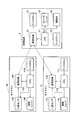
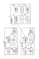
- FIG. 1 is a block diagram showing a mobile terminal of the first embodiment.
- FIG. 2 is a conceptual diagram showing a user who wears the right earphone and the left earphone and possesses the mobile terminals of the first to seventh embodiments.
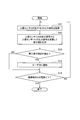
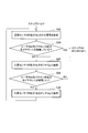
- FIG. 3 is a flowchart showing a process executed in the mobile terminal of the first embodiment.
- FIG. 4 is a flowchart showing a preferable process executed in the mobile terminal of the first embodiment.
- FIG. 5 is a block diagram showing a mobile terminal of the second embodiment.
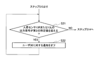
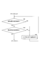
- FIG. 6 is a flowchart showing a first example of processing executed in the mobile terminal of the second embodiment.
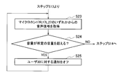
- FIG. 7 is a flowchart showing a second example of processing executed in the mobile terminal of the second embodiment.
- FIG. 1 is a block diagram showing a mobile terminal of the first embodiment.
- FIG. 2 is a conceptual diagram showing a user who wears the right earphone and the left earphone and possesses the mobile terminals of the first to seventh embodiments.
- FIG. 8 is a block diagram showing a mobile terminal of the third embodiment.
- FIG. 9 is a flowchart showing a first example of processing executed in the mobile terminal of the third embodiment.
- FIG. 10 is a timing chart showing a first example of processing executed in the mobile terminal of the third embodiment.
- FIG. 11 is a flowchart showing a second example of processing executed in the mobile terminal of the third embodiment.
- FIG. 12 is a block diagram showing a mobile terminal according to the fourth embodiment.
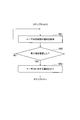
- FIG. 13 is a flowchart showing a process executed in the mobile terminal of the fourth embodiment.
- FIG. 14 is a block diagram showing a mobile terminal according to the fifth embodiment.
- FIG. 15 is a flowchart showing a process executed in the mobile terminal of the fifth embodiment.
- FIG. 16 is a block diagram showing a mobile terminal of the sixth embodiment.
- FIG. 17 is a flowchart showing a process executed in the mobile terminal of the sixth embodiment.
- FIG. 18 is a block diagram showing a mobile terminal according to the seventh embodiment.
- FIG. 19 is a flowchart showing a process executed in the mobile terminal of the seventh embodiment.
- FIG. 20 shows the relationship between the change in the position of the user and the change in the signal strength of the output signal of the motion sensor when the heat source stopped due to the movement of the user moves relatively close to and away from the user. It is a figure which shows.
- FIG. 21 is a flowchart showing a preferable process executed in the mobile terminal of the seventh embodiment.
- FIG. 22 is a diagram showing an example of a state in which it is assumed that the user does not recognize the stopped heat source.
- the mobile terminals of the first to seventh embodiments will be described with reference to the attached drawings.
- the same parts may be designated by the same reference numerals and the description thereof may be omitted.
- the user 30 wears the right earphone 1R and the left earphone 1L on the right ear and the left ear, respectively.
- the right earphone 1R and the left earphone 1L are provided with motion sensors 13R and 13L, respectively.
- the user 30 has a mobile terminal 2 that communicates with the right earphone 1R and the left earphone 1L.
- the mobile terminal 2 may be a smartphone.
- the right earphone 1R includes a central processing unit (CPU) 11R, a vibration unit 12R, and a communication circuit 14R in addition to the motion sensor 13R.
- the left earphone 1L includes a CPU 11L, a vibration unit 12L, and a communication circuit 14L in addition to the motion sensor 13L.
- the mobile terminal 2 includes a CPU 21, a speaker unit 22, a communication circuit 24, a display 25, and a vibrating unit 26.
- the motion sensors 13R and 13L detect whether or not a person is around by measuring far infrared rays or peripheral potentials.
- the vibration units 12R and 12L may be a speaker unit having a diaphragm and a magnetic circuit for driving the diaphragm, or may be a bone conduction unit having a bone conduction device.
- the communication circuits 14R and 14L communicate with the communication circuit 24 of the mobile terminal 2 in accordance with any short-range wireless communication standard such as Bluetooth (registered trademark).
- the mobile terminal 2 may include a memory for storing the music file, reproduce the music file, and transmit the audio data of the music file to the right earphone 1R and the left earphone 1L by the communication circuit 24.
- the vibrating unit 26 is a so-called vibrator that transmits vibration to the user 30.
- the communication circuit 14R transmits the output signal of the motion sensor 13R to the mobile terminal 2.
- the communication circuit 14L transmits the output signal of the motion sensor 13R to the mobile terminal 2.
- the CPU 21 can detect that a person has approached the user 30 based on the output signal of the motion sensor 13R or 13L received by the communication circuit 24.
- the motion sensors 13R and 13L measure far infrared rays and the like emitted by the user 30 wearing the right earphone 1R and the left earphone 1L, so that the motion sensors 13R and 13L are predetermined even if a third party is not approaching. Generates the output signal of. Therefore, it may not be possible to accurately detect a third party approaching the user 30 to be notified to the user 30.
- the CPU 21 subtracts the output signal of the motion sensor 13R received by the communication circuit 24 and the output signal of the motion sensor 13L from each other.
- the communication circuit 24 receives the output signals of the motion sensors 13R and 13L in a state where there is no third party around the user 30, and the CPU 21 subtracts the output signals of both, it becomes almost 0. That is, when the CPU 21 subtracts the output signals of the motion sensors 13R and 13L from each other, the output signal generated by detecting the user 30 can be removed.
- the output signal of the motion sensor 13R and the output signal of the motion sensor 13L have substantially the same signal strength.
- both the motion sensor 13R or 13L, or both the motion sensors 13R and 13L measure far infrared rays and the like emitted by the third party in addition to the far infrared rays and the like emitted by the user 30. , Generate an output signal.
- the CPU 21 generates a difference value by subtracting the output signal of the motion sensor 13R and the output signal of the motion sensor 13L received by the communication circuit 24 from each other. Since the output signal generated by detecting the user 30 as described above is removed, the CPU 21 can determine that a third party has approached the user 30 if the difference value is equal to or greater than a predetermined value. it can.
- the CPU 21 transmits a predetermined voice signal to the right earphone 1R and the left earphone 1L in order to notify the user 30 that a person has approached.
- the CPU 21 may generate sound from the speaker unit 22, display characters or images indicating that a person has approached the display 25, or vibrate the vibrating unit 26.
- the CPU 21 subtracts the output signal of the motion sensor 13L from the output signal of the motion sensor 13R, and if the difference value is positive and equal to or greater than a predetermined value, the third party is approaching the user 30 from the right. I understand. If the difference value is negative and equal to or less than a predetermined value (the absolute value of the difference value is equal to or greater than a predetermined value), it can be seen that the third party is approaching the user 30 from the left.
- the CPU 21 may transmit an audio signal to the right earphone 1R or the left earphone 1L in the direction in which a third party is approaching. From the ratio of the signal strength of the output signal of the motion sensor 13R and the output signal of the motion sensor 13L, the direction in which a third party approaches can be known. The CPU 21 may notify the user 30 of the direction.
- step S11 the CPU 21 acquires the output signals of the motion sensors 13R and 13L in step S11.
- step S12 the CPU 21 subtracts the output signal of the motion sensor 13L from the output signal of the motion sensor 13R to generate a difference value.
- the CPU 21 may subtract the output signal of the motion sensor 13R from the output signal of the motion sensor 13L.
- step S13 the CPU 21 determines whether or not a third party is approaching based on the difference value obtained by subtracting the output signal of the motion sensor 13L from the output signal of the motion sensor 13R. If the absolute value of the difference value is equal to or greater than a predetermined value, the CPU 21 determines that a third party is approaching. If no third party is approaching (NO), the CPU 21 shifts the process to step S15. If a third party is approaching (YES), the CPU 21 notifies the user 30 by any of the above methods in step S14, and shifts the process to step S15.
- the CPU 21 determines in step S15 whether or not the power of the mobile terminal 2 has been turned off. If the power is not turned off (NO), the CPU 21 repeats the processes of steps S11 to S15, and if the power is turned off (YES), the CPU 21 ends the process.
- the notification to the user 30 in step S14 may be stopped when the user 30 performs an operation to stop the notification, or may be automatically stopped after a predetermined time.
- the following method can be considered as a method of removing the output signal generated by the motion sensors 13R and 13L detecting the user 30.
- the storage unit stores the output signals of the motion sensors 13R and 13L in a state where a third party is not approaching the user 30 as right and left basic output signals.
- the CPU 21 subtracts the right basic output signal from the output signal of the motion sensor 13R when a third party approaches the user 30, and subtracts the left basic output signal from the output signal of the motion sensor 13L.
- a third party is at the same distance from the motion sensor 13R and the motion sensor 13L in front of or directly behind the user 30. If you approach while moving on the line, you cannot detect the approach of a third party. However, since it is extremely rare for a third party to approach the user 30 in this way, it does not matter substantially.
- the motion sensor 13R will not be approached by a third party.
- the output signal and the output signal of the motion sensor 13L may not have substantially the same signal strength.
- the CPU 21 acquires the output signals of the motion sensors 13R and 13L in step S01.
- step S02 the CPU 21 multiplies the output signals of the motion sensors 13R and 13L by a predetermined weighting coefficient to weight them.
- step S03 the CPU 21 subtracts the output signal of the weighted motion sensor 13L from the output signal of the weighted motion sensor 13R to generate a difference value.
- step S04 the CPU 21 determines whether or not the difference value is equal to or less than the first predetermined value.
- the first predetermined value is set to a small value.
- step S04 If the difference value is not equal to or less than the first predetermined value in step S04 (NO), the CPU 21 changes the weighting coefficient in step S05 and repeats the processes of steps S01 to S05.
- the processes of steps S01 to S05 are executed in a state where there is no third party around the user 30. By repeating the processes of steps S01 to S05, a weighting coefficient whose difference value is equal to or less than the first predetermined value can be obtained.
- the CPU 21 determines the weighting coefficient for the output signals of the motion sensors 13R and 13L in step S06.
- the weighting coefficient for the output signal of one of the motion sensors 13R and 13L may be 1.
- the initial setting for determining the weighting coefficient is completed by the processing of steps S01 to S06.
- the CPU 21 acquires the output signals of the motion sensors 13R and 13L in step S11.
- the CPU 21 weights with the weighting coefficient determined in step S120, subtracts the output signal of the motion sensor 13L from the output signal of the motion sensor 13R to generate a difference value, and shifts the process to step S13. ..
- the processing of steps S13 to 15 is the same as that in FIG.
- the weighting coefficient is gradually changed to determine the weighting coefficient at which the difference value is equal to or less than the first predetermined value, but the weighting coefficient may be determined as follows.
- the output signal of the motion sensor 13R is S1
- the output signal of the motion sensor 13L is S2.
- the weighting coefficients for the output signals S1 and S2 are ⁇ 1 and ⁇ 2.
- the difference value is ⁇ 1 ⁇ S1- ⁇ 2 ⁇ S2. If the weighting coefficient ⁇ 1 is 1 and the weighting coefficient ⁇ 2 is S1 / S2, the difference value can be 0. Since the weighting coefficients ⁇ 1 and ⁇ 2 are different for each user 30, they are set individually for each user 30.
- the communication circuit 24 communicates with the right earphone 1R worn on the right ear of the user 30 and the left earphone 1L worn on the left ear.
- the communication circuit 24 includes a first output signal generated by the motion sensor 13R (first motion sensor) provided on the right earphone 1R and a motion sensor 13L (second motion sensor) provided on the left earphone 1L. Receives the second output signal generated by the motion sensor).
- the CPU 21 functions as a detection unit, and detects whether or not a third party has approached the user 30 based on the difference value between the first output signal and the second output signal received by the communication circuit 24.
- the notification unit described later notifies the user 30 that the third party has approached.
- the CPU 21 and the first output signal so that the difference value between the first output signal and the second output signal is equal to or less than the first predetermined value in a state where a third party is not approaching the user 30. It is better to multiply the second output signal by the weighting factor.
- the communication circuit 24 functions as a notification unit, and the communication circuit 24 transmits an audio signal notifying the user 30 that a third party has approached to at least one of the right earphone 1R and the left earphone 1L.
- the audio signal may be transmitted to the right earphone 1R
- the audio signal may be transmitted to the left earphone 1L.
- a stereo audio signal such that sound can be heard from the direction in which the user 30 approaches the user 30 may be transmitted to the right earphone 1R and the left earphone 1L in response to the direction in which the third party approaches the user 30.
- the speaker unit 22 may generate a voice notifying the user 30 that a third party has approached as a notification unit.
- the display 25 may display characters or images notifying the user 30 that a third party has approached.
- the vibration unit 26 may notify the user 30 by vibration that a third party has approached.
- the motion sensors 13R and 13L remove the output signal generated by detecting the user 30, it is a third party approaching the user and should be notified to the user. It is possible to accurately detect and notify the three parties.
- the user 30 is notified of the approach of a third party even when there are a plurality of people around the user 30.
- the mobile terminal 2 of the second embodiment is configured so as not to notify the user 30 of the approach of a third party when there are a plurality of people around the user 30.
- the right earphone 1R is provided with a microphone 17R
- the left earphone 1L is provided with a microphone 17L
- the mobile terminal 2 includes a microphone 27.
- the microphones 17R, 17L, and 27 may be noise canceling microphones. Only the mobile terminal 2 is provided with the microphone 27, and the right earphone 1R and the left earphone 1L do not have to be provided with the microphones 17R and 17L. Only the right earphone 1R and the left earphone 1L are provided with the microphones 17R and 17L, and the mobile terminal 2 does not have to be provided with the microphone 27.
- the microphones 17R and 17L transmit the audio signal picked up by the microphones 17R and 17L to the mobile terminal 2.
- the right earphone 1R and the left earphone 1L may transmit the volume to the mobile terminal 2 based on the voice signals picked up by the microphones 17R and 17L.
- Steps S21 and S22 shown in FIG. 6 are provided between step S13 and step S14 of FIG. 3 or FIG.
- the CPU 21 determines in step S21 whether or not the output signal of the motion sensor 13R or 13L exceeds the second predetermined value. judge.
- the second predetermined value is set to a large value.
- the CPU 21 shifts the process to step S14 of FIG. 3 or 4, and a third party approaches the user 30. Notify that you are doing it. If the output signal of the motion sensor 13R or 13L exceeds the second predetermined value (YES), the CPU 21 turns off the notification to the user 30 in step S22 and returns the process to step S21.
- microphones 17R, 17L, and 27 are not used in the first configuration example shown in FIG.
- Steps S23 to S25 shown in FIG. 7 are provided between step S13 and step S14 in FIG. 3 or FIG.
- step S13 of FIG. 3 or FIG. 4 the CPU 21 outputs an audio signal (or volume) from any of the microphones 17R, 17L, and 27 in step S23. get.
- step S24 the CPU 21 determines whether or not the volume exceeds a predetermined volume. If the volume does not exceed a predetermined volume (NO), the CPU 21 shifts the process to step S14 of FIG. 3 or 4, and notifies the user 30 that a third party is approaching. If the volume exceeds a predetermined volume (YES), the CPU 21 turns off the notification to the user 30 in step S25 and returns the process to step S23.
- the CPU 21 turns off the notification by the notification unit when it is determined that a plurality of third parties exist around the user 30.
- the CPU 21 determines that there are a plurality of third parties around the user 30 and turns off the notification by the notification unit.
- the voice signal picked up by the microphone (17R, 17L, or 27) provided in the right earphone 1R, the left earphone 1L, or the mobile terminal 2 exceeds a predetermined volume, the CPU 21 has a plurality of third parties around the user 30. It may be determined that there are three parties, and the notification by the notification unit may be turned off.
- the user 30 is notified of the approach of a third party when there are a plurality of people around the user 30. You can avoid it.
- the motion sensors 13R and 13L consume a large amount of power, the motion sensors 13R and 13L should be turned off when the user 30 does not wear the right earphone 1R or the left earphone 1L on the right ear or the left ear and is not using the sensor. Is preferable.
- the mobile terminal 2 of the third embodiment is configured to turn off the motion sensors 13R and 13L when the user 30 is not using the right earphone 1R or the left earphone 1L.
- the right earphone 1R includes a proximity sensor 18R
- the left earphone 1L includes a proximity sensor 18L.
- the right earphone 1R and the left earphone 1L transmit the output signals of the proximity sensors 18R and 18L to the mobile terminal 2.
- Steps S31 to S34 shown in FIG. 9 are provided between steps S11 and S12 in FIG. 3 or between steps S11 and S120 in FIG.
- the CPU 21 acquires the output signals of the motion sensors 13R and 13L in step S11 of FIG. 3 or FIG. 4, the process proceeds to step S31.
- step S31 the CPU 21 determines whether or not the output signal of the motion sensor 13R or 13L is equal to or less than the third predetermined value.
- the third predetermined value is a value smaller than the value of the output signal when the user 30 wears the right earphone 1R and the left earphone 1L and there is no third party around the user 30, for example, a value of 0.8 times. And. If the output signals of the motion sensors 13R and 13L are not equal to or less than the third predetermined value (NO), it is determined that the user 30 is wearing the right earphone 1R and the left earphone 1L, so that the CPU 21 processes the process in step S12. Or shift to S120.
- step S31 If the output signal of the motion sensor 13R or 13L is equal to or less than the third predetermined value in step S31, it is determined that the user 30 is not wearing the right earphone 1R or the left earphone 1L. Instructs the right earphone 1R and the left earphone 1L to turn off the motion sensors 13R and 13L at predetermined time intervals.
- step S33 the CPU 21 determines whether or not the output signal exceeds the third predetermined value during the period when the motion sensors 13R and 13L are on. If the output signal does not exceed the third predetermined value (NO), it is determined that the user 30 has not yet worn the right earphone 1R or the left earphone 1L, so that the CPU 21 repeats the processes of steps S32 and S33.
- step S34 the CPU 21 instructs the right earphone 1R and the left earphone 1L to turn on the motion sensors 13R and 13L, and returns the process to step S31.
- the motion sensors 13R and 13L repeat on and off.
- the value of the output signal exceeds the third predetermined value as shown in (a). Then, as shown in (b), the motion sensors 13R and 13L are always turned on.
- proximity sensors 18R and 18L are not used in the first configuration example shown in FIG.
- the CPU 21 acquires the output signals of the proximity sensors 18R and 18L in step S35.
- step S36 the CPU 21 determines whether or not the user 30 is wearing the right earphone 1R and the left earphone 1L based on the values of the output signals of the proximity sensors 18R and 18L. If the output signals of the proximity sensors 18R and 18L are equal to or higher than a predetermined value, it can be determined that the user 30 is wearing the right earphone 1R and the left earphone 1L.
- step S36 If the user 30 is wearing the right earphone 1R and the left earphone 1L in step S36 (YES), the CPU 21 shifts the process to step S12 or S120. If the user 30 is not wearing the right earphone 1R or the left earphone 1L in step S36 (NO), the CPU 21 sets the right earphone 1R and the left earphone 1L to turn off the motion sensors 13R and 13L in step S37. Instruct.
- step S38 the CPU 21 determines whether or not the user 30 has attached the right earphone 1R and the left earphone 1L based on the values of the output signals of the proximity sensors 18R and 18L. If the user 30 does not wear the right earphone 1R or the left earphone 1L (NO), the CPU 21 repeats the processes of steps S37 and S38. If the user 30 wears the right earphone 1R and the left earphone 1L (YES), the CPU 21 instructs the right earphone 1R and the left earphone 1L to turn on the motion sensors 13R and 13L in step S39, and performs processing. Return to step S35.
- the CPU 21 determines whether or not the user 30 wears the right earphone 1R and the left earphone 1L on the right ear and the left ear.
- the CPU 21 determines that the user 30 is not wearing the right earphone 1R and the left earphone 1L
- the CPU 21 instructs the right earphone 1R and the left earphone 1L to turn off the motion sensors 13R and 13L at least intermittently.
- the CPU 21 can determine whether or not the user 30 is wearing the right earphone 1R and the left earphone 1L based on whether or not the first and second output signals are equal to or less than the third predetermined value.
- the third predetermined value is a value smaller than the first and second output signals when the user 30 wears the right earphone 1R and the left earphone 1L and there is no third party around the user 30, and is less than 1. It is the value obtained by multiplying the coefficient of.
- the CPU 21 determines that the user 30 is not wearing the right earphone 1R and the left earphone 1L, the CPU 21 instructs the right earphone 1R and the left earphone 1L to turn off the motion sensors 13R and 13L at predetermined time intervals. To do.
- the CPU 21 can determine whether or not the user 30 is wearing the right earphone 1R and the left earphone 1L based on the output signals of the proximity sensors 18R and 18L. In this case, when it is determined that the user 30 is not wearing the right earphone 1R or the left earphone 1L, the CPU 21 instructs the right earphone 1R and the left earphone 1L to turn off the motion sensors 13R and 13L.
- the motion sensor 13R and the human sensor 13R and the user 30 do not use the right earphone 1R or the left earphone 1L.
- 13L can be turned off at least intermittently. Therefore, the power consumption of the right earphone 1R and the left earphone 1L can be reduced.
- ⁇ Fourth Embodiment> It may be preferable to notify the user 30 of the approach of a third party only in a specific place such as a low-traffic road. In addition, it may be preferable to notify the user 30 of the approach of a third party only at a specific time such as at night.
- the mobile terminal 2 of the fourth embodiment is configured to notify the user 30 of the approach of a third party only at a specific place or only at a specific time.
- the mobile terminal 2 includes a GNSS receiving unit 28 that receives GNSS signals from a plurality of satellites for the Global Navigation Satellite System (GNSS).
- GNSS is GPS (Global Positioning System) as an example.
- the CPU 21 calculates the current position of the mobile terminal 2 based on the GNSS signals from three or more satellites received by the GNSS receiving unit 28.
- the CPU 21 acquires the current time based on the GNSS signal.
- the method of acquiring the current position and the current time of the mobile terminal 2 is not limited to the method based on the GNSS signal.
- a processor other than the CPU 21 may calculate the current position of the mobile terminal 2 based on the GNSS signal and supply the position information to the CPU 21.
- the current position may be calculated based on the position of the base station of the mobile phone line or wireless LAN.
- the mobile terminal 2 may acquire the current time based on the standard radio wave.
- the non-volatile memory 29 stores information on a preset location (designated area) and information on a time (designated time) that notifies the user 30 of the approach of a third party.
- the user 30 operates an operation unit (not shown) to set a designated area and a designated time and stores the designated area and the designated time in the non-volatile memory 29.
- a designated area may be set by latitude and longitude, or a chome or street of a specific town may be set as a designated area.
- a designated time may be set by a combination of a start time at which the notification of approach is started and an end time at which the notification of approach ends, or a designated time may be set such as 3 hours from the predetermined time.
- Steps S41 and S42 shown in FIG. 13 are provided between step S13 and step S14 of FIG. 3 or FIG.
- the CPU 21 determines in step S41 whether or not the current position is within the designated area. If the current position is not within the designated area (NO), the CPU 21 turns off the notification to the user 30 in step S43 and returns the process to step S41.
- step S42 determines in step S42 whether or not the current time is within the designated time. If the current time is not within the specified time (NO), the CPU 21 turns off the notification to the user 30 in step S43 and returns the process to step S41. If the current time is within the designated time (YES), the CPU 21 shifts the process to step S14.
- the current position is within the designated area, and the user 30 is notified of the approach of a third party only when the current time is within the designated time.
- the current position is irrespective of the current time. May notify the user 30 of the approach of a third party when is within the designated area. Further, the user 30 may be notified of the approach of a third party when the current time is within the designated time regardless of the current position.
- the mobile terminal 2 of the fourth embodiment includes a current position acquisition unit for acquiring the current position and a storage unit for storing a designated area indicating a place for notifying the user 30 of the approach of a third party.
- the CPU 21 and the GNSS receiving unit 28 are examples of the current position acquisition unit.
- the non-volatile memory 29 is an example of a storage unit. The CPU 21 turns off the notification to the user 30 when the current position is not within the designated area.
- the mobile terminal 2 of the fourth embodiment includes a current time acquisition unit for acquiring the current time and a storage unit for storing a designated time indicating a time for notifying the user 30 of the approach of a third party.
- the CPU 21 and the GNSS receiving unit 28 are examples of the current time acquisition unit.
- the non-volatile memory 29 is an example of a storage unit.
- the storage unit that stores the designated area and the storage unit that stores the designated time may be the same storage unit or may be different storage units.
- the CPU 21 turns off the notification to the user 30 when the current time is not the specified time.
- a third party approaches the user 30 only at a specific place or only at a specific time. Can be notified. Since the approach of a third party is not notified at a place or time where notification is not required, it is possible to prevent unnecessary notification. It is desirable to turn off the motion sensors 13R and 13L in order to reduce power consumption in areas other than the designated area.
- ⁇ Fifth Embodiment> When the user 30 is on a high-speed moving object such as a train, a car, or an airplane, it is not necessary to notify the user 30 of the approach of a third party. When the user 30 is traveling at low speed, such as when traveling by bicycle or riding a skateboard or roller skates, it is better to notify the user 30 of the approach of a third party. ..
- the mobile terminal 2 of the fifth embodiment is configured to turn off the notification to the user 30 when it is assumed that the user is on a high-speed mobile body.
- the right earphone 1R includes an acceleration sensor 101R
- the left earphone 1L includes an acceleration sensor 101L
- the right earphone 1R and the left earphone 1L transmit the output signals of the acceleration sensors 101R and 101L to the mobile terminal 2.
- the mobile terminal 2 includes an acceleration sensor 201. Only the mobile terminal 2 includes the acceleration sensor 201, and the right earphone 1R and the left earphone 1L do not have to include the acceleration sensors 101R and 101L. Only the right earphone 1R and the left earphone 1L are provided with the acceleration sensors 101R and 101L, and the mobile terminal 2 does not have to be provided with the acceleration sensor 201.
- Step S51 and S52 shown in FIG. 15 are provided between step S13 and step S14 of FIG. 3 or FIG.
- the CPU 21 determines whether or not the user 30 is moving at high speed based on the output signal of the acceleration sensor 101R, 101L, or 201.
- the high speed is 30 km / h or more.
- the CPU 21 integrates the acceleration detected by the acceleration sensors 101R, 101L, or 201 to obtain the speed.
- the CPU 21 determines that the user 30 is moving at a high speed. If the user 30 is not moving at high speed (NO), the CPU 21 shifts the process to step S14. If the user 30 is moving at high speed (YES), the CPU 21 turns off the notification to the user 30 in step S52 and returns the process to step S51.
- the mobile terminal 2 of the fifth embodiment includes a movement speed acquisition unit that acquires the movement speed of the user 30.
- the CPU 21 functions as a moving speed acquisition unit.
- the notification unit turns off the notification to the user 30 when the movement speed of the user 30 acquired by the movement speed acquisition unit is equal to or higher than a predetermined speed.
- the movement speed acquisition unit can obtain the movement speed of the user 30 based on the acceleration acquired by the acceleration sensor 101R, 101L, or 201 provided in the right earphone 1R, the left earphone 1L, or the mobile terminal 2.
- the user 30 is not notified when riding on a high-speed moving object such as a train, a car, or an airplane. Can be done.
- the right earphone 1R includes an acceleration sensor 101R and a geomagnetic sensor 102R
- the left earphone 1L includes an acceleration sensor 101L and a geomagnetic sensor 102L.
- the right earphone 1R and the left earphone 1L transmit the output signals of the acceleration sensors 101R and 101L and the output signals of the geomagnetic sensors 102R and 102L to the mobile terminal 2. It is not essential to provide the geomagnetic sensors 102R and 102L, but it is preferable to provide them.
- Steps S61 to S63 shown in FIG. 17 are provided between step S14 and step S15 of FIG. 3 or FIG. After the CPU 21 detects the approach of a third party and notifies the user 30, the CPU 21 acquires the movement of the head of the user 30 in step S61.
- the CPU 21 may acquire the movement of the head of the user 30 based on the output signals of the acceleration sensors 101R and 101L, or based on the output signals of the acceleration sensors 101R and 101L and the output signals of the geomagnetic sensors 102R and 102L. it can.
- the CPU 21 acquires the movement of the head based on the output signals of the geomagnetic sensors 102R and 102L in addition to the output signals of the acceleration sensors 101R and 101L, the movement of the head can be acquired with higher accuracy.
- step S62 the CPU 21 determines whether or not it is assumed that the user 30 has confirmed the third party based on the movement of the head. If the face of the user 30 faces the approaching third party and then the face returns to the original direction, it can be assumed that the third party has been confirmed. Unless it is assumed that the user 30 has confirmed the third party (NO), the CPU 21 repeats the processes of steps S61 and S62. If it is assumed that the user 30 has confirmed the third party (YES), the CPU 21 turns off the notification to the user 30 in step S63 and shifts the process to step S15.
- the mobile terminal 2 of the sixth embodiment includes a movement acquisition unit that acquires the movement of the head of the user 30.
- the CPU 21 functions as a motion acquisition unit that acquires the motion of the head of the user 30 based on at least the output signals of the acceleration sensors 101R and 101L.
- the notification unit After the notification unit notifies the user 30 that a third party has approached, if the movement acquisition unit acquires a movement that the head of the user 30 is supposed to have confirmed the third party, the notification unit will be the user. Turn off notifications for 30.
- the mobile terminal 2 of the sixth embodiment may turn off the notification to the user 30 when it is assumed that the user 30 has confirmed a third party. it can. Therefore, it is possible to prevent the user 30 from being notified more than necessary.
- the CPU 21 may detect the approach of the third party and notify the user 30. Since the motion sensors 13R and 13L detect far infrared rays generated by a heat source, they may detect a stopped vehicle or the like and notify the user 30. Even if there is an arbitrary heat source that is stopped, including a third party, and the motion sensor 13R or 13L generates an output signal due to the movement of the user 30 and the heat source being relatively close to the user 30. There is no need to notify the user 30.
- the mobile terminal 2 of the seventh embodiment notifies the user 30 when any stopped heat source approaches the user 30 relatively and the CPU 21 detects that a third party has approached the user 30. It is configured to turn off.
- the right earphone 1R includes an acceleration sensor 101R and a geomagnetic sensor 102R
- the left earphone 1L includes an acceleration sensor 101L and a geomagnetic sensor 102L.
- the right earphone 1R and the left earphone 1L transmit the output signals of the acceleration sensors 101R and 101L and the output signals of the geomagnetic sensors 102R and 102L to the mobile terminal 2.
- the mobile terminal 2 includes a GNSS receiving unit 28. Calculate the current position of the mobile terminal 2.
- Steps S71 to S75 shown in FIG. 19 are provided between step S13 of FIG. 3 or FIG. 4 and step S14 or step S15.
- the CPU 21 acquires the signal strengths of the output signals of the motion sensors 13R and 13L at predetermined intervals in step S71.
- the CPU 21 acquires the position of the user 30 for a predetermined time.
- the CPU 21 may intermittently acquire the position of the user 30 within a predetermined time.
- the CPU 21 calculates the relationship between the change in the position of the user 30 and the change in the signal strength of the output signal.
- FIG. 20 it is assumed that the user 30 moves on the straight line Ls from the left side to the right side. It is assumed that there is a third party 40 stopped at a position 0 as the position x of the straight line Ls and at a position separated from the straight line Ls by a predetermined distance in a direction orthogonal to the straight line Ls. At this time, the signal strength of the output signal of the motion sensor 13L gradually increases as the user 30 approaches the position 0, and gradually decreases as the user 30 passes the position 0 and moves away from the position 0. In the characteristic diagram showing the relationship between the position x and the signal strength, the white circles indicate the signal strength of the output signal acquired at predetermined intervals in step S71.
- the CPU 21 acquires the current position of the mobile terminal 2 (user 30) based on the GNSS signal, but since the position accuracy is not so high, the CPU 21 acquires the position of the user 30 based on the output signal of the acceleration sensor 101R or 101L. Therefore, it is better to improve the position accuracy.
- Position information can be obtained by integrating the acceleration, which is the output signal of the acceleration sensor 101R or 101L, and converting it into a velocity, and further integrating the velocity.
- the signal strength of the position x and the output signal of the motion sensor 13R or 13L Has a relationship of k / (x 2 ), where k is the constant of proportionality.
- the relationship between the change in the position of the user 30 and the change in the signal strength is proportional to 1 / (x 2 ) based on the position of at least 3 points of the user 30 and the signal strength of at least 3 points of the output signal. It is possible to determine whether or not the stopped heat source is in a state of being relatively close to the user 30 depending on whether or not the heat source is stopped.
- the CPU 21 determines in step S74 whether or not the heat source is stopped. If the heat source is not stopped (NO), the CPU 21 shifts the process to step S14 to notify the user 30 that a third party is approaching. If the heat source is stopped (YES), the CPU 21 turns off the notification to the user 30 in step S75 and shifts the process to step S15.
- the output signals of the geomagnetic sensors 102R and 102L are not used.
- step S74 the CPU 21 acquires the direction of the head of the user 30 based on the output signals of the geomagnetic sensors 102R and 102L in step S76.
- the CPU 21 determines in step S77 whether or not the user 30 is looking aside. As shown in FIG. 22, when the user 30 is moving from the left side to the right side on the straight line Ls and the head direction of the user 30 is not facing the third party 40 side as shown by the alternate long and short dash line, the user. It is assumed that 30 does not recognize the third party 40. In such a case, the CPU 21 determines that the user 30 is looking aside (YES), shifts the process to step S14, and notifies the user 30 that a third party is approaching.
- the CPU 21 can be in a state of looking aside when the user 30 is deviated by 30 degrees or more with respect to the direction in which the user 30 moves to the side where the stopped heat source does not exist.
- step S77 If the CPU 21 determines in step S77 that the user 30 is not looking aside (NO), the CPU 21 turns off the notification to the user 30 in step S75 and shifts the process to step S15.
- the mobile terminal 2 of the seventh embodiment includes a notification control unit that controls the notification unit so as to turn off the notification to the user 30 in such a state.
- the CPU 21 functions as a notification control unit.
- the stopped heat source is relatively close to the user 30 based on the relationship between the change in the position of the user 30 due to the movement of the user 30 and the change in the signal strength of the output signal of the motion sensor 13R or 13L. It is possible to detect the state of
- the CPU 21 detects a state in which the stopped heat source is relatively close to the user 30, the heat source in which the user 30 is stopped is based on the direction in which the user 30 moves and the direction of the head of the user 30. It is preferable to determine whether or not it is assumed that the user does not recognize. When it is assumed that the user 30 does not recognize the stopped heat source, the CPU 21 preferably controls the notification unit so as not to turn off the notification to the user 30.
- the mobile terminal 2 of the seventh embodiment in addition to the same effect as that of the mobile terminal 2 of the first embodiment, there is a stopped heat source, and the heat source is relative to the user 30 when the user 30 moves. It is possible to prevent the user 30 from being notified of the approach of a third party when approaching the target. Further, according to the mobile terminal 2 of the seventh embodiment, when it is assumed that the stopped heat source is not recognized, the approach of a third party can be notified.
- the present invention is not limited to the first to seventh embodiments described above, and various modifications can be made without departing from the gist of the present invention.
- the second to seventh embodiments can be combined arbitrarily. It is also possible to configure the first to seventh embodiments with a computer program that causes the CPU to execute the processing of each embodiment.
Landscapes
- Physics & Mathematics (AREA)
- Engineering & Computer Science (AREA)
- Signal Processing (AREA)
- Acoustics & Sound (AREA)
- General Physics & Mathematics (AREA)
- Business, Economics & Management (AREA)
- Emergency Management (AREA)
- Telephone Function (AREA)
Abstract
通信回路(24)は、ユーザの右耳に装着される右イヤホン(1R)及び左耳に装着される左イヤホン(1L)と通信して、右イヤホン(1R)に備えられている第1の人感センサ(13R)が生成した第1の出力信号と、左イヤホン(1L)に備えられている第2の人感センサ(13L)が生成した第2の出力信号とを受信する。検出部(CPU21)は、通信回路(24)が受信した第1の出力信号と第2の出力信号との差分値に基づいて、ユーザに第三者が接近したか否かを検出する。通知部は、検出部がユーザに第三者が接近したことを検出したとき、ユーザに第三者が接近したことを通知する。
Description
本開示は、人感センサを備えるイヤホンと通信する携帯端末に関する。
特許文献1には、イヤホンを装着したユーザに接近する人を検知して、ユーザに知らせることが記載されている。
ユーザに接近する第三者であってユーザに知らせるべき第三者を的確に検知して知らせることができる携帯端末が求められている。
実施形態の第1の態様によれば、ユーザの右耳に装着される右イヤホン及び左耳に装着される左イヤホンと通信して、前記右イヤホンに備えられている第1の人感センサが生成した第1の出力信号と、前記左イヤホンに備えられている第2の人感センサが生成した第2の出力信号とを受信する通信回路と、前記通信回路が受信した前記第1の出力信号と前記第2の出力信号との差分値に基づいて、前記ユーザに第三者が接近したか否かを検出する検出部と、前記検出部が前記ユーザに第三者が接近したことを検出したとき、前記ユーザに第三者が接近したことを通知する通知部とを備える携帯端末が提供される。
実施形態の携帯端末によれば、ユーザに接近する第三者であってユーザに知らせるべき第三者を的確に検知して知らせることができる。
以下、第1~第7実施形態の携帯端末について、添付図面を参照して説明する。第1~第7実施形態の携帯端末において、同一部分には同一符号を付し、その説明を省略することがある。
<第1実施形態>
図2に示すように、ユーザ30は、右耳及び左耳にそれぞれ右イヤホン1R及び左イヤホン1Lを装着している。右イヤホン1R及び左イヤホン1Lはそれぞれ人感センサ13R及び13Lを備える。ユーザ30は、右イヤホン1R及び左イヤホン1Lと通信する携帯端末2を所持している。携帯端末2はスマートフォンであってもよい。
図2に示すように、ユーザ30は、右耳及び左耳にそれぞれ右イヤホン1R及び左イヤホン1Lを装着している。右イヤホン1R及び左イヤホン1Lはそれぞれ人感センサ13R及び13Lを備える。ユーザ30は、右イヤホン1R及び左イヤホン1Lと通信する携帯端末2を所持している。携帯端末2はスマートフォンであってもよい。
図1に示すように、右イヤホン1Rは、人感センサ13Rの他に、中央処理装置(CPU)11R、振動ユニット12R、通信回路14Rを備える。左イヤホン1Lは、人感センサ13Lの他に、CPU11L、振動ユニット12L、通信回路14Lを備える。携帯端末2は、CPU21、スピーカユニット22、通信回路24、ディスプレイ25、振動部26を備える。
人感センサ13R及び13Lは、遠赤外線または周辺電位を測定することによって人が周囲にいるか否かを検知する。振動ユニット12R及び12Lは、振動板と振動板を駆動する磁気回路とを有するスピーカユニットであってもよいし、骨伝導デバイスを有する骨伝導ユニットであってもよい。通信回路14R及び14Lは、ブルートゥース(登録商標)等の任意の近距離無線通信規格に従って携帯端末2の通信回路24と通信する。
携帯端末2は、楽曲ファイルを記憶するメモリを備え、楽曲ファイルを再生して通信回路24によって右イヤホン1R及び左イヤホン1Lに楽曲ファイルの音声データを送信してもよい。振動部26はユーザ30に振動を伝達するいわゆるバイブレータである。
人感センサ13Rが人を検知すると、通信回路14Rによって人感センサ13Rの出力信号を携帯端末2に送信する。人感センサ13Lが人を検知すると、通信回路14Lによって人感センサ13Rの出力信号を携帯端末2に送信する。原理的には、CPU21は、通信回路24が受信した人感センサ13Rまたは13Lの出力信号に基づいてユーザ30に人が接近したことを検出することができる。
ところが、実際には、人感センサ13R及び13Lは右イヤホン1R及び左イヤホン1Lを装着しているユーザ30が発している遠赤外線等を測定するので、第三者が接近していなくても所定の出力信号を生成する。よって、ユーザ30に知らせるべきユーザ30に接近する第三者を的確に検知できないことがある。
そこで、CPU21は、通信回路24が受信した人感センサ13Rの出力信号と人感センサ13Lの出力信号とを互いに減算する。通信回路24が、ユーザ30の周囲に第三者がいない状態における人感センサ13R及び13Lの出力信号を受信してCPU21が両者の出力信号を互いに減算すると、ほぼ0となる。即ち、CPU21が人感センサ13R及び13Lの出力信号を互いに減算すると、ユーザ30を検知することによって生成された出力信号を除去することができる。ここでは、人感センサ13Rの出力信号と人感センサ13Lの出力信号とがほぼ同じ信号強度であるとみなす。
ユーザ30に第三者が接近すると、人感センサ13Rもしくは13L、または人感センサ13R及び13Lの双方は、ユーザ30が発する遠赤外線等に加えて第三者が発する遠赤外線等も測定して、出力信号を生成する。CPU21は、通信回路24が受信した人感センサ13Rの出力信号と人感センサ13Lの出力信号とを互いに減算して差分値を生成する。上記のようにユーザ30を検知することによって生成された出力信号は除去されるから、CPU21は、差分値が所定の値以上であれば、ユーザ30に第三者が接近したと判定することができる。
CPU21は、差分値が所定の値以上であれば、ユーザ30に人が接近したことを知らせるため、右イヤホン1R及び左イヤホン1Lに所定の音声信号を送信する。CPU21は、スピーカユニット22より音を発生させてもよく、ディスプレイ25に人が接近したことを示す文字または画像を表示してもよく、振動部26を振動させてもよい。
CPU21が人感センサ13Rの出力信号から人感センサ13Lの出力信号を減算し、差分値が正で所定の値以上であれば、第三者はユーザ30に右方向から接近していることが分かる。差分値が負で所定の値以下(差分値の絶対値が所定の値以上)であれば、第三者はユーザ30に左方向から接近していることが分かる。CPU21は、第三者が接近している方向の右イヤホン1Rまたは左イヤホン1Lに音声信号を送信してもよい。人感センサ13Rの出力信号と人感センサ13Lの出力信号との信号強度の比から第三者が接近する方向が分かる。CPU21は、ユーザ30に方向を知らせてもよい。
図3に示すフローチャートを用いて、携帯端末2で実行される処理を説明する。携帯端末2の図示していない電源がオンされて携帯端末2が動作を開始すれば、CPU21は、ステップS11にて、人感センサ13R及び13Lの出力信号を取得する。CPU21は、ステップS12にて、人感センサ13Rの出力信号から人感センサ13Lの出力信号を減算して差分値を生成する。これによって、人感センサ13R及び13Lがユーザ30を感知した信号成分がほぼ除去される。CPU21は、人感センサ13Lの出力信号から人感センサ13Rの出力信号を減算してもよい。
CPU21は、ステップS13にて、人感センサ13Rの出力信号から人感センサ13Lの出力信号を減算した差分値に基づき、第三者が接近しているか否かを判定する。CPU21は、差分値の絶対値が所定の値以上であれば、第三者が接近していると判定する。第三者が接近していなければ(NO)、CPU21は、処理をステップS15に移行させる。第三者が接近していれば(YES)、CPU21は、ステップS14にて、上記の任意の方法でユーザ30に通知して処理をステップS15に移行させる。
CPU21は、ステップS15にて、携帯端末2の電源がオフされたか否かを判定する。CPU21は、電源がオフされなければ(NO)、ステップS11~S15の処理を繰り返し、電源がオフされれば(YES)、処理を終了させる。なお、ステップS14におけるユーザ30への通知は、ユーザ30が通知を停止する操作をしたときに停止させてもよいし、所定時間後に自動的に停止させるようにしてもよい。
ところで、人感センサ13R及び13Lがユーザ30を検知することによって生成した出力信号を除去する方法として、次の方法が考えられる。記憶部は、ユーザ30に第三者が接近していない状態での人感センサ13R及び13Lの出力信号を右及び左の基礎出力信号として記憶する。CPU21は、ユーザ30に第三者が接近した状態における人感センサ13Rの出力信号から右の基礎出力信号を減算し、人感センサ13Lの出力信号から左の基礎出力信号を減算する。
このような方法では、人感センサ13R及び13Lが遠赤外線で熱を検知する方法を採用しているとき、ユーザ30が例えば運動することによって体温が上昇すると、体温の上昇分がノイズとなる。実際にはユーザ30に第三者が接近していないにもかかわらず、第三者が接近していると誤検出することがある。上述した人感センサ13Rの出力信号と人感センサ13Lの出力信号とを互いに減算する方法では、誤検出が少なく高精度に第三者の接近を検知することができる。
なお、人感センサ13Rの出力信号と人感センサ13Lの出力信号とを互いに減算する方法では、第三者がユーザ30の正面または真後ろで人感センサ13Rと人感センサ13Lとからの等距離線上を移動しながら接近すると、第三者の接近を検出できない。しかしながら、第三者がこのようにユーザ30に接近することは極めて稀であるから、実質的に問題とならない。
人感センサ13Rの感度と人感センサ13Lの感度とが異なったり、ユーザ30の左右の耳の温度が異なったりすると、ユーザ30に第三者が接近していない状態で、人感センサ13Rの出力信号と人感センサ13Lの出力信号とはほぼ同じ信号強度とはならないことがある。人感センサ13Rの出力信号と人感センサ13Lの出力信号とが異なるときには、重み付け係数を乗算することによって両者の信号強度を合わせることが好ましい。
図4に示すフローチャートを用いて、人感センサ13Rの出力信号と人感センサ13Lの出力信号の信号強度を合わせる処理を含む、携帯端末2で実行される好ましい処理を説明する。
CPU21は、ステップS01にて、人感センサ13R及び13Lの出力信号を取得する。CPU21は、ステップS02にて、人感センサ13R及び13Lの出力信号に対して所定の重み付け係数を乗算して重み付けする。CPU21は、ステップS03にて、重み付けした人感センサ13Rの出力信号から重み付けした人感センサ13Lの出力信号を減算して差分値を生成する。CPU21は、ステップS04にて、差分値が第1の所定値以下であるか否かを判定する。第1の所定値は小さな値に設定される。
ステップS04にて差分値が第1の所定値以下でなければ(NO)、CPU21は、ステップS05にて重み付け係数を変更して、ステップS01~S05の処理を繰り返す。ステップS01~S05の処理は、ユーザ30の周囲に第三者がいない状態で実行される。ステップS01~S05の処理を繰り返せば、差分値が第1の所定値以下となる重み付け係数が得られる。
ステップS04にて差分値が第1の所定値以下であれば、CPU21は、ステップS06にて、人感センサ13R及び13Lの出力信号に対する重み付け係数を決定する。なお、人感センサ13R及び13Lのうちの一方の出力信号に対する重み付け係数は1であってもよい。ステップS01~S06の処理によって重み付け係数を決定する初期設定が完了する。
CPU21は、ステップS11にて、人感センサ13R及び13Lの出力信号を取得する。CPU21は、ステップS120にて、決定した重み付け係数で重み付けして、人感センサ13Rの出力信号から人感センサ13Lの出力信号を減算して差分値を生成して、処理をステップS13に移行させる。ステップS13~15の処理は図3と同じである。
図4に示す例では、重み付け係数を徐々に変更して差分値が第1の所定値以下となる重み付け係数を決定しているが、重み付け係数を次のように決定してもよい。人感センサ13Rの出力信号をS1、人感センサ13Lの出力信号をS2とする。出力信号S1及びS2に対する重み付け係数をα1及びα2とする。α1×S1-α2×S2が差分値となる。重み付け係数α1を1、重み付け係数α2をS1/S2とすれば、差分値を0とすることができる。重み付け係数α1及びα2はユーザ30ごとに異なるから、各ユーザ30に対して個別に設定される。
以上のように、第1実施形態の携帯端末2において、通信回路24は、ユーザ30の右耳に装着される右イヤホン1R及び左耳に装着される左イヤホン1Lと通信する。通信回路24は、右イヤホン1Rに備えられている人感センサ13R(第1の人感センサ)が生成した第1の出力信号と、左イヤホン1Lに備えられている人感センサ13L(第2の人感センサ)が生成した第2の出力信号とを受信する。
CPU21は検出部として機能し、通信回路24が受信した第1の出力信号と第2の出力信号との差分値に基づいて、ユーザ30に第三者が接近したか否かを検出する。後述する通知部は、CPU21がユーザ30に第三者が接近したことを検出したとき、ユーザ30に第三者が接近したことを通知する。
CPU21は、ユーザ30に第三者が接近していない状態で、第1の出力信号と第2の出力信号との差分値が第1の所定値以下となるように、第1の出力信号と第2の出力信号とに重み付け係数を乗算するのがよい。
通信回路24は通知部として機能し、通信回路24が、ユーザ30に第三者が接近したことを知らせる音声信号を右イヤホン1Rと左イヤホン1Lとのうちの少なくとも一方に送信する。第三者がユーザ30に右方向から接近しているときには音声信号を右イヤホン1Rに送信し、左方向から接近しているときには音声信号を左イヤホン1Lに送信してもよい。第三者がユーザ30に接近する方向に対応して、ユーザ30が接近する方向から音が聞こえるようなステレオ音声信号を右イヤホン1R及び左イヤホン1Lに送信してもよい。
スピーカユニット22は通知部として、ユーザ30に第三者が接近したことを知らせる音声を発生してもよい。ディスプレイ25は通知部として、ユーザ30に第三者が接近したことを知らせる文字または画像を表示してもよい。振動部26は通知部として、ユーザ30に第三者が接近したことを振動によって知らせてもよい。
第1実施形態の携帯端末2によれば、人感センサ13R及び13Lがユーザ30を検知することによって生成した出力信号を除去するので、ユーザに接近する第三者であってユーザに知らせるべき第三者を的確に検知して知らせることができる。
<第2実施形態>
第1実施形態の携帯端末2においては、ユーザ30の周囲に複数の人がいる状況でもユーザ30に第三者の接近を通知してしまう。第2実施形態の携帯端末2は、ユーザ30の周囲に複数の人がいる状況ではユーザ30に第三者の接近を通知しないように構成している。
第1実施形態の携帯端末2においては、ユーザ30の周囲に複数の人がいる状況でもユーザ30に第三者の接近を通知してしまう。第2実施形態の携帯端末2は、ユーザ30の周囲に複数の人がいる状況ではユーザ30に第三者の接近を通知しないように構成している。
図5において、右イヤホン1Rはマイクロホン17Rを備え、左イヤホン1Lはマイクロホン17Lを備える。携帯端末2はマイクロホン27を備える。マイクロホン17R、17L、及び27は、ノイズキャンセル用のマイクロホンであってもよい。携帯端末2のみがマイクロホン27を備え、右イヤホン1R及び左イヤホン1Lはマイクロホン17R及び17Lを備えなくてもよい。右イヤホン1R及び左イヤホン1Lのみがマイクロホン17R及び17Lを備え、携帯端末2はマイクロホン27を備えなくてもよい。
マイクロホン17R及び17Lは、マイクロホン17R及び17Lが収音した音声信号を携帯端末2に送信する。右イヤホン1R及び左イヤホン1Lは、マイクロホン17R及び17Lが収音した音声信号に基づき音量を携帯端末2に送信してもよい。
図6に示すフローチャートを用いて、携帯端末2で実行されるユーザ30の周囲に複数の人がいる状況で第三者の接近を通知しないよう処理する第1の例を説明する。図6に示すステップS21及びS22は、図3または図4のステップS13とステップS14との間に設けられる。図3または図4のステップS13にて第三者の接近が検出されると、CPU21は、ステップS21にて、人感センサ13Rまたは13Lの出力信号が第2の所定値を超えるか否かを判定する。第2の所定値は大きな値に設定される。
人感センサ13Rまたは13Lの出力信号が第2の所定値を超えるということは、ユーザ30の周囲に複数の人がいると考えられる。そこで、人感センサ13Rまたは13Lの出力信号が第2の所定値を超えなければ(NO)、CPU21は処理を図3または図4のステップS14に移行させて、ユーザ30に第三者が接近していることを通知する。人感センサ13Rまたは13Lの出力信号が第2の所定値を超えれば(YES)、CPU21は、ステップS22にて、ユーザ30に対する通知をオフして、処理をステップS21に戻す。
なお、図6に示す第1の構成例においては、マイクロホン17R、17L、及び27は使用されない。
図7に示すフローチャートを用いて、携帯端末2で実行されるユーザ30の周囲に複数の人がいる状況で第三者の接近を通知しないよう処理する第2の例を説明する。図7に示すステップS23~S25は、図3または図4のステップS13とステップS14との間に設けられる。
図3または図4のステップS13にて第三者の接近が検出されると、CPU21は、ステップS23にて、マイクロホン17R、17L、及び27のうちのいずれかからの音声信号(または音量)を取得する。CPU21は、ステップS24にて、音量が所定の音量を超えるか否かを判定する。音量が所定の音量を超えなければ(NO)、CPU21は処理を図3または図4のステップS14に移行させて、ユーザ30に第三者が接近していることを通知する。音量が所定の音量を超えれば(YES)、CPU21は、ステップS25にて、ユーザ30に対する通知をオフして、処理をステップS23に戻す。
以上のように、第2実施形態の携帯端末2においては、CPU21は、ユーザ30の周囲に複数の第三者が存在すると判断されるとき、通知部による通知をオフする。CPU21は、第1または第2の出力信号が第2の所定値を超えるとき、ユーザ30の周囲に複数の第三者が存在すると判断して、通知部による通知をオフする。CPU21は、右イヤホン1R、左イヤホン1L、または携帯端末2に備えられたマイクロホン(17R、17L、または27)が収音した音声信号が所定の音量を超えるとき、ユーザ30の周囲に複数の第三者が存在すると判断して、通知部による通知をオフしてもよい。
第2実施形態の携帯端末2によれば、第1実施形態の携帯端末2と同様の効果に加えて、ユーザ30の周囲に複数の人がいる状況でユーザ30に第三者の接近を通知しないようすることができる。
<第3実施形態>
人感センサ13R及び13Lは消費電力が多いため、ユーザ30が右イヤホン1Rまたは左イヤホン1Lを右耳または左耳に装着せず使用していない状況では、人感センサ13R及び13Lをオフすることが好ましい。第3実施形態の携帯端末2は、ユーザ30が右イヤホン1Rまたは左イヤホン1Lを使用していない状況で人感センサ13R及び13Lをオフするように構成している。
人感センサ13R及び13Lは消費電力が多いため、ユーザ30が右イヤホン1Rまたは左イヤホン1Lを右耳または左耳に装着せず使用していない状況では、人感センサ13R及び13Lをオフすることが好ましい。第3実施形態の携帯端末2は、ユーザ30が右イヤホン1Rまたは左イヤホン1Lを使用していない状況で人感センサ13R及び13Lをオフするように構成している。
図8において、右イヤホン1Rは近接センサ18Rを備え、左イヤホン1Lは近接センサ18Lを備える。右イヤホン1R及び左イヤホン1Lは、近接センサ18R及び18Lの出力信号を携帯端末2に送信する。
図9に示すフローチャート及び図10に示すタイミングチャートを用いて、ユーザ30が右イヤホン1Rまたは左イヤホン1Lを使用していない状況で人感センサ13R及び13Lをオフするよう処理する第1の例を説明する。図9に示すステップS31~S34は、図3のステップS11とステップS12との間、または図4のステップS11とステップS120との間に設けられる。図3または図4のステップS11にてCPU21が人感センサ13R及び13Lの出力信号を取得すると、処理はステップS31に移行される。
CPU21は、ステップS31にて、人感センサ13Rまたは13Lの出力信号が第3の所定値以下であるか否かを判定する。第3の所定値は、ユーザ30が右イヤホン1R及び左イヤホン1Lを装着してユーザ30の周囲に第三者がいない状態における出力信号の値より小さい値である、例えば0.8倍の値とする。人感センサ13R及び13Lの出力信号が第3の所定値以下でなければ(NO)、ユーザ30は右イヤホン1R及び左イヤホン1Lを装着していると判断されるので、CPU21は処理をステップS12またはS120に移行させる。
ステップS31にて人感センサ13Rまたは13Lの出力信号が第3の所定値以下であれば、ユーザ30は右イヤホン1Rまたは左イヤホン1Lを装着していないと判断されるので、CPU21は、ステップS32にて、人感センサ13R及び13Lを所定の時間ごとにオフするよう右イヤホン1R及び左イヤホン1Lに指示する。
CPU21は、ステップS33にて、人感センサ13R及び13Lをオンしている期間に出力信号が第3の所定値を超えるか否かを判定する。出力信号が第3の所定値を超えなければ(NO)、ユーザ30は右イヤホン1Rまたは左イヤホン1Lを依然として装着していないと判断されるので、CPU21は、ステップS32及びS33の処理を繰り返す。
ステップS33にて出力信号が第3の所定値を超えれば(YES)、ユーザ30は右イヤホン1R及び左イヤホン1Lを装着したと判断される。そこで、CPU21は、ステップS34にて、人感センサ13R及び13Lをオンするよう右イヤホン1R及び左イヤホン1Lに指示して、処理をステップS31に戻す。
図10において、時刻t1においてユーザ30が右イヤホン1Rまたは左イヤホン1Lを外すと、(a)に示すように、出力信号の値は第3の所定値以下となり、(b)に示すように、人感センサ13R及び13Lはオンとオフとを繰り返す。人感センサ13R及び13Lがオンされている時刻t2においてユーザ30が右イヤホン1R及び左イヤホン1Lを装着すると、(a)に示すように、出力信号の値は第3の所定値を超える。すると、(b)に示すように、人感センサ13R及び13Lは常時オンされる。
なお、図9に示す第1の構成例においては、近接センサ18R及び18Lは使用されない。
図11に示すフローチャートを用いて、ユーザ30が右イヤホン1R及び左イヤホン1Lを使用していない状況で人感センサ13R及び13Lをオフするよう処理する第2の例を説明する。CPU21は、ステップS35にて、近接センサ18R及び18Lの出力信号を取得する。CPU21は、ステップS36にて、近接センサ18R及び18Lの出力信号の値に基づき、ユーザ30が右イヤホン1R及び左イヤホン1Lを装着しているか否かを判定する。近接センサ18R及び18Lの出力信号が所定の値以上であれば、ユーザ30が右イヤホン1R及び左イヤホン1Lを装着していると判定できる。
ステップS36にてユーザ30が右イヤホン1R及び左イヤホン1Lを装着していれば(YES)、CPU21は処理をステップS12またはS120に移行させる。ステップS36にてユーザ30が右イヤホン1Rまたは左イヤホン1Lを装着していなければ(NO)、CPU21は、ステップS37にて、人感センサ13R及び13Lをオフするよう右イヤホン1R及び左イヤホン1Lに指示する。
CPU21は、ステップS38にて、近接センサ18R及び18Lの出力信号の値に基づき、ユーザ30が右イヤホン1R及び左イヤホン1Lを装着したか否かを判定する。ユーザ30が右イヤホン1Rまたは左イヤホン1Lを装着しなければ(NO)、CPU21は、ステップS37及びS38の処理を繰り返す。ユーザ30が右イヤホン1R及び左イヤホン1Lを装着すれば(YES)、CPU21は、ステップS39にて、人感センサ13R及び13Lをオンするよう右イヤホン1R及び左イヤホン1Lに指示して、処理をステップS35に戻す。
以上のように、第3実施形態の携帯端末2において、CPU21は、ユーザ30が右イヤホン1R及び左イヤホン1Lを右耳及び左耳に装着しているか否かを判定する。CPU21は、ユーザ30が右イヤホン1R及び左イヤホン1Lを装着していないと判定したとき、人感センサ13R及び13Lを少なくとも間欠的にオフするよう、右イヤホン1R及び左イヤホン1Lに指示する。
CPU21は、第1及び第2の出力信号が第3の所定値以下であるか否か基づいて、ユーザ30が右イヤホン1R及び左イヤホン1Lを装着しているか否かを判定することができる。第3の所定値は、ユーザ30が右イヤホン1R及び左イヤホン1Lを装着してユーザ30の周囲に第三者がいない状態における第1及び第2の出力信号より小さい値であって、1未満の係数を乗算した値である。
この場合、CPU21は、ユーザ30が右イヤホン1R及び左イヤホン1Lを装着していないと判定したとき、人感センサ13R及び13Lを所定の時間ごとにオフするよう右イヤホン1R及び左イヤホン1Lに指示する。
CPU21は、近接センサ18R及び18Lの出力信号に基づいて、ユーザ30が右イヤホン1R及び左イヤホン1Lを装着しているか否かを判定することができる。この場合、CPU21は、ユーザ30が右イヤホン1Rまたは左イヤホン1Lを装着していないと判定したとき、人感センサ13R及び13Lをオフするよう右イヤホン1R及び左イヤホン1Lに指示する。
第3実施形態の携帯端末2によれば、第1実施形態の携帯端末2と同様の効果に加えて、ユーザ30が右イヤホン1Rまたは左イヤホン1Lを使用していない状況で人感センサ13R及び13Lを少なくとも間欠的にオフすることができる。よって、右イヤホン1R及び左イヤホン1Lの消費電力を低減することができる。
<第4実施形態>
人通りの少ない道路等の特定の場所においてのみ、ユーザ30に対して第三者の接近を通知することが好ましい場合がある。また、夜間のような特定の時間のみ、ユーザ30に対して第三者の接近を通知することが好ましい場合がある。第4実施形態の携帯端末2は、特定の場所においてのみ、または特定の時間のみ、ユーザ30に対して第三者の接近を通知するように構成している。
人通りの少ない道路等の特定の場所においてのみ、ユーザ30に対して第三者の接近を通知することが好ましい場合がある。また、夜間のような特定の時間のみ、ユーザ30に対して第三者の接近を通知することが好ましい場合がある。第4実施形態の携帯端末2は、特定の場所においてのみ、または特定の時間のみ、ユーザ30に対して第三者の接近を通知するように構成している。
図12において、携帯端末2は、全地球航法衛星システム(Global Navigation Satellite System: GNSS)用の複数の衛星からのGNSS信号を受信するGNSS受信部28を備える。GNSSは、一例としてGPS(Global Positioning System)である。CPU21は、GNSS受信部28が受信した3つ以上の衛星からのGNSS信号に基づいて、携帯端末2の現在位置を算出する。CPU21は、GNSS信号に基づいて現在時刻を取得する。
携帯端末2の現在位置及び現在時刻の取得方法はGNSS信号に基づく方法に限定されない。CPU21以外のプロセッサがGNSS信号に基づいて携帯端末2の現在位置を算出して、CPU21に位置情報を供給してもよい。携帯電話回線または無線LANの基地局の位置に基づいて現在位置を算出してもよい。携帯端末2は標準電波に基づいて現在時刻を取得してもよい。
不揮発性メモリ29には、ユーザ30に対して第三者の接近を通知する、予め設定された場所(指定領域)の情報及び時間(指定時間)の情報が記憶されている。ユーザ30は、図示していない操作部を操作して指定領域及び指定時間を設定して不揮発性メモリ29に記憶させる。指定領域は緯度と経度とで指定領域が設定されていてもよいし、特定の町の丁目または通りが指定領域とされてもよい。接近の通知を開始する開始時刻と終了する終了時刻との組み合わせで指定時間が設定されてもよいし、所定の時刻から3時間のように指定時間が設定されてもよい。
図13に示すフローチャートを用いて、特定の場所において、かつ特定の時間のみ、ユーザ30に対して第三者の接近を通知する処理を説明する。図13に示すステップS41及びS42は、図3または図4のステップS13とステップS14との間に設けられる。
図13において、CPU21は、ステップS41にて、現在位置は指定領域内であるか否かを判定する。現在位置が指定領域内でなければ(NO)、CPU21は、ステップS43にて、ユーザ30に対する通知をオフして、処理をステップS41に戻す。
現在位置が指定領域内であれば(YES)、CPU21は、ステップS42にて、現在時刻が指定時間内であるか否かを判定する。現在時刻が指定時間内でなければ(NO)、CPU21は、ステップS43にて、ユーザ30に対する通知をオフして、処理をステップS41に戻す。現在時刻が指定時間内であれば(YES)、CPU21は処理をステップS14に移行させる。
図13では、現在位置は指定領域内であり、現在時刻が指定時間内であるときのみ、ユーザ30に対して第三者の接近を通知するようにしているが、現在時刻に関係なく現在位置が指定領域内であるときに、ユーザ30に対して第三者の接近を通知してもよい。また、現在位置に関係なく現在時刻が指定時間内であるときに、ユーザ30に対して第三者の接近を通知してもよい。
以上のように、第4実施形態の携帯端末2は、現在位置を取得する現在位置取得部と、ユーザ30に第三者の接近を通知する場所を示す指定領域を記憶する記憶部を備える。CPU21及びGNSS受信部28は現在位置取得部の一例である。不揮発性メモリ29は記憶部の一例である。CPU21は、現在位置が指定領域内でないとき、ユーザ30に対する通知をオフする。
第4実施形態の携帯端末2は、現在時刻を取得する現在時刻取得部と、ユーザ30に第三者の接近を通知する時間を示す指定時間を記憶する記憶部を備える。CPU21及びGNSS受信部28は現在時刻取得部の一例である。不揮発性メモリ29は記憶部の一例である。なお、指定領域を記憶する記憶部と指定時間を記憶する記憶部とは同じ記憶部あってもよく、異なる記憶部であってもよい。CPU21は、現在時刻が指定時間でないとき、ユーザ30に対する通知をオフする。
第4実施形態の携帯端末2によれば、第1実施形態の携帯端末2と同様の効果に加えて、特定の場所においてのみ、または特定の時間のみ、ユーザ30に対して第三者の接近を通知することができる。通知の必要のない場所または時間で第三者の接近を通知しないので、無駄な通知をしないようすることができる。なお、指定領域以外では消費電力を減らすために人感センサ13R及び13Lをオフにするのが望ましい。
<第5実施形態>
ユーザ30が、電車、自動車、飛行機等の高速の移動体に乗っているときには、ユーザ30に対して第三者の接近を通知する必要がない。ユーザ30が、自転車で移動しているとき、スケートボードまたはローラースケートに乗っているときのように、低速で移動しているときには、ユーザ30に対して第三者の接近を通知した方がよい。第5実施形態の携帯端末2は、高速の移動体に乗っていると想定されるとき、ユーザ30に対する通知をオフするように構成している。
ユーザ30が、電車、自動車、飛行機等の高速の移動体に乗っているときには、ユーザ30に対して第三者の接近を通知する必要がない。ユーザ30が、自転車で移動しているとき、スケートボードまたはローラースケートに乗っているときのように、低速で移動しているときには、ユーザ30に対して第三者の接近を通知した方がよい。第5実施形態の携帯端末2は、高速の移動体に乗っていると想定されるとき、ユーザ30に対する通知をオフするように構成している。
図14において、右イヤホン1Rは加速度センサ101Rを備え、左イヤホン1Lは加速度センサ101Lを備える。右イヤホン1R及び左イヤホン1Lは、加速度センサ101R及び101Lの出力信号を携帯端末2に送信する。携帯端末2は、加速度センサ201を備える。携帯端末2のみが加速度センサ201を備え、右イヤホン1R及び左イヤホン1Lは加速度センサ101R及び101Lを備えなくてもよい。右イヤホン1R及び左イヤホン1Lのみが加速度センサ101R及び101Lを備え、携帯端末2は加速度センサ201を備えなくてもよい。
図15に示すフローチャートを用いて、高速の移動体に乗っていると想定されるとき、ユーザ30に対する通知をオフする処理を説明する。図15に示すステップS51及びS52は、図3または図4のステップS13とステップS14との間に設けられる。CPU21は、ステップS51にて、加速度センサ101R、101L、または201の出力信号に基づき、ユーザ30が高速で移動しているか否かを判定する。
例えば、30km/h以上を高速とする。CPU21は、加速度センサ101R、101L、または201が検出した加速度を積分して速度を求める。CPU21は、求めたユーザ30の移動速度が30km/h以上であるとき、高速で移動していると判定する。ユーザ30が高速で移動していなければ(NO)、CPU21は処理をステップS14に移行させる。ユーザ30が高速で移動していれば(YES)、CPU21は、ステップS52にて、ユーザ30に対する通知をオフして、処理をステップS51に戻す。
以上のように、第5実施形態の携帯端末2は、ユーザ30の移動速度を取得する移動速度取得部を備える。CPU21は移動速度取得部として機能する。通知部は、移動速度取得部が取得したユーザ30の移動速度が所定の速度以上であるとき、ユーザ30に対する通知をオフする。移動速度取得部は、右イヤホン1R、左イヤホン1L、または携帯端末2に備えられた加速度センサ101R、101L、または201が取得した加速度に基づいて、ユーザ30の移動速度を求めることができる。
第5実施形態の携帯端末2によれば、第1実施形態の携帯端末2と同様の効果に加えて、電車、自動車、飛行機等の高速の移動体に乗っているときにユーザ30に通知しないようにすることができる。
<第6実施形態>
CPU21がユーザ30に第三者が接近していることを検出して、ユーザ30に通知したとき、ユーザ30が第三者を認識すればユーザ30に対する通知を継続する必要はない。第6実施形態の携帯端末2は、ユーザ30が第三者を確認したと想定されるとき、ユーザ30に対する通知をオフするように構成している。
CPU21がユーザ30に第三者が接近していることを検出して、ユーザ30に通知したとき、ユーザ30が第三者を認識すればユーザ30に対する通知を継続する必要はない。第6実施形態の携帯端末2は、ユーザ30が第三者を確認したと想定されるとき、ユーザ30に対する通知をオフするように構成している。
図16において、右イヤホン1Rは加速度センサ101R及び地磁気センサ102Rを備え、左イヤホン1Lは加速度センサ101L及び地磁気センサ102Lを備える。右イヤホン1R及び左イヤホン1Lは、加速度センサ101R及び101Lの出力信号と地磁気センサ102R及び102Lの出力信号を携帯端末2に送信する。地磁気センサ102R及び102Lを設けることは必須ではないが、設けることが好ましい。
図17に示すフローチャートを用いて、ユーザ30が第三者を確認したと想定されるとき、ユーザ30に対する通知をオフする処理を説明する。図17に示すステップS61~S63は、図3または図4のステップS14とステップS15との間に設けられる。CPU21が第三者の接近を検出してユーザ30に通知した後、CPU21は、ステップS61にて、ユーザ30の頭部の動きを取得する。
CPU21は、加速度センサ101R及び101Lの出力信号に基づいて、または、加速度センサ101R及び101Lの出力信号及び地磁気センサ102R及び102Lの出力信号に基づいて、ユーザ30の頭部の動きを取得することができる。CPU21が加速度センサ101R及び101Lの出力信号に加えて、地磁気センサ102R及び102Lの出力信号に基づいて頭部の動きを取得すると、頭部の動きをより高精度に取得することができる。
CPU21は、ステップS62にて、頭部の動きに基づいてユーザ30が第三者を確認したと想定されるか否かを判定する。ユーザ30の顔が接近する第三者の方を向き、その後に顔が元の向きに戻るような動きをすれば、第三者を確認したと想定することができる。ユーザ30が第三者を確認したと想定されなければ(NO)、CPU21は、ステップS61及びS62の処理を繰り返す。ユーザ30が第三者を確認したと想定されれば(YES)、CPU21は、ステップS63にて、ユーザ30に対する通知をオフして、処理をステップS15に移行させる。
以上のように、第6実施形態の携帯端末2は、ユーザ30の頭部の動きを取得する動き取得部を備える。CPU21は、少なくとも加速度センサ101R及び101Lの出力信号に基づいてユーザ30の頭部の動きを取得する動き取得部として機能する。通知部がユーザ30に対して第三者が接近したことを通知した後に、動き取得部が、ユーザ30の頭部が第三者を確認したと想定される動きを取得したら、通知部はユーザ30に対する通知をオフする。
第6実施形態の携帯端末2は、第1実施形態の携帯端末2と同様の効果に加えて、ユーザ30が第三者を確認したと想定されるとき、ユーザ30に対する通知をオフすることができる。よって、必要以上にユーザ30に通知しないようにすることができる。
<第7実施形態>
第三者が停止していても、ユーザ30と第三者との距離が短くなっていくと、CPU21は第三者の接近を検出してユーザ30に通知することがある。人感センサ13R及び13Lは熱源が発生する遠赤外線を検出するので、停止している自動車等を検出してユーザ30に通知することもある。第三者を含む停止している任意の熱源が存在し、ユーザ30が移動して熱源がユーザ30に相対的に接近することによって、人感センサ13Rまたは13Lが出力信号を生成しても、ユーザ30に通知する必要はない。
第三者が停止していても、ユーザ30と第三者との距離が短くなっていくと、CPU21は第三者の接近を検出してユーザ30に通知することがある。人感センサ13R及び13Lは熱源が発生する遠赤外線を検出するので、停止している自動車等を検出してユーザ30に通知することもある。第三者を含む停止している任意の熱源が存在し、ユーザ30が移動して熱源がユーザ30に相対的に接近することによって、人感センサ13Rまたは13Lが出力信号を生成しても、ユーザ30に通知する必要はない。
第7実施形態の携帯端末2は、停止している任意の熱源がユーザ30に相対的に接近して、CPU21がユーザ30に第三者が接近したと検出するときに、ユーザ30に対する通知をオフするように構成している。
図18において、右イヤホン1Rは加速度センサ101R及び地磁気センサ102Rを備え、左イヤホン1Lは加速度センサ101L及び地磁気センサ102Lを備える。右イヤホン1R及び左イヤホン1Lは、加速度センサ101R及び101Lの出力信号と地磁気センサ102R及び102Lの出力信号を携帯端末2に送信する。携帯端末2はGNSS受信部28を備える。携帯端末2の現在位置を算出する。
図19に示すフローチャートを用いて、停止している熱源がユーザ30に相対的に接近する状況でユーザ30に対する通知をオフする処理を説明する。図19に示すステップS71~S75は、図3または図4のステップS13とステップS14またはステップS15との間に設けられる。
図19において、CPU21は、ステップS71にて、人感センサ13R及び13Lの出力信号の信号強度を所定間隔で取得する。CPU21は、ステップS72にて、ユーザ30の位置を所定時間取得する。CPU21は、ユーザ30の位置を所定時間内に間欠的に取得してもよい。CPU21は、ステップS73にて、ユーザ30の位置の変化と出力信号の信号強度の変化との関係を算出する。
図20において、ユーザ30は直線Ls上を左側から右側へと移動するとする。直線Lsの位置xとして位置0であって、直線Lsと直交する方向に直線Lsから所定の距離だけ離れた位置に、停止している第三者40が存在するとする。このとき、人感センサ13Lの出力信号の信号強度は、ユーザ30が位置0に近付くに従って漸増し、位置0を過ぎて位置0から離れるに従って漸減する。位置xと信号強度との関係を示す特性図において白丸はステップS71にて所定間隔で取得した出力信号の信号強度を示す。
CPU21は、GNSS信号に基づいて携帯端末2(ユーザ30)の現在位置を取得するが、位置精度がさほど高精度でないため、加速度センサ101Rまたは101Lの出力信号に基づいてユーザ30の位置を取得して、位置精度を向上させるのがよい。加速度センサ101Rまたは101Lの出力信号である加速度を積分して速度に変換し、速度をさらに積分することによって位置情報を得ることができる。
図20に示すように、第三者40等の停止している任意の熱源が存在し、ユーザ30が直線的に移動するときの、位置xと人感センサ13Rまたは13Lの出力信号の信号強度とは、比例定数をkとすると、k/(x2)の関係を有する。CPU21は、ユーザ30の少なくとも3点の位置と出力信号の少なくとも3点の信号強度とに基づいて、ユーザ30の位置の変化と信号強度の変化との関係が1/(x2)に比例しているか否かによって、停止している熱源がユーザ30に相対的に接近する状態であるか否かを判定することができる。
この原理に基づき、CPU21は、ステップS74にて、熱源が停止しているか否かを判定する。熱源が停止していなければ(NO)、CPU21は、処理をステップS14に移行させて、ユーザ30に第三者が接近していることを通知する。熱源が停止していれば(YES)、CPU21は、ステップS75にて、ユーザ30に対する通知をオフして、処理をステップS15に移行させる。
なお、図19に示す処理においては、地磁気センサ102R及び102Lの出力信号は使用されない。
図20に示すような状況においては、停止している熱源がユーザ30に相対的に接近してもユーザ30に通知する必要はないとしたが、ユーザ30が脇見等で停止している熱源を認識していないと想定されるときには、ユーザ30に通知することが好ましい。
図21に示すフローチャートを用いて、図19に示す処理に加えて、ユーザ30が熱源を認識していないと想定されるときにユーザ30に通知するようにした処理を説明する。図21において、ステップS74にて、熱源が停止していれば(YES)、CPU21は、ステップS76にて、地磁気センサ102R及び102Lの出力信号に基づいてユーザ30の頭部の向きを取得する。
CPU21は、ステップS77にて、ユーザ30は脇見をしているか否かを判定する。図22に示すように、ユーザ30が直線Ls上を左側から右側へと移動していて、ユーザ30の頭部の向きが一点鎖線で示すように第三者40側を向いていないとき、ユーザ30は第三者40を認識していないと想定される。このようなとき、CPU21は、ユーザ30は脇見をしている(YES)と判定して、処理をステップS14に移行させて、ユーザ30に第三者が接近していることを通知する。
ユーザ30が移動する方向と頭部の向きとが何度以上ずれているときに脇見をしている状態とするかは、適宜に設定すればよい。例えば、CPU21は、停止している熱源が存在していない側にユーザ30が移動する方向に対して30度以上ずれているときに、脇見をしている状態とすることができる。
CPU21は、ステップS77にてユーザ30は脇見をしていない(NO)と判定すれば、ステップS75にて、ユーザ30に対する通知をオフして、処理をステップS15に移行させる。
以上のように、停止している任意の熱源が存在し、ユーザ30が移動することによって停止している熱源がユーザ30に相対的に接近すると、人感センサ13Rまたは13Lが出力信号を生成する。すると、CPU21は、ユーザ30に第三者が接近したと検出する。第7実施形態の携帯端末2は、このような状態で、ユーザ30に対する通知をオフするよう通知部を制御する通知制御部を備える。CPU21は、通知制御部として機能する。
CPU21は、ユーザ30の移動によるユーザ30の位置の変化と、人感センサ13Rまたは13Lの出力信号の信号強度の変化との関係に基づいて、停止している熱源がユーザ30に相対的に接近する状態を検出することができる。
CPU21は、停止している熱源がユーザ30に相対的に接近する状態を検出したとき、ユーザ30が移動する方向とユーザ30の頭部の向きとに基づいて、ユーザ30が停止している熱源を認識していないと想定されるか否かを判定することが好ましい。CPU21は、ユーザ30が停止している熱源を認識していないと想定されるとき、ユーザ30に対する通知をオフしないよう通知部を制御することが好ましい。
第7実施形態の携帯端末2によれば、第1実施形態の携帯端末2と同様の効果に加えて、停止している熱源が存在し、ユーザ30が移動することによって熱源がユーザ30に相対的に接近するときに、ユーザ30に第三者の接近を通知しないようにすることができる。また、第7実施形態の携帯端末2によれば、停止している熱源を認識していないと想定されるときに、第三者の接近を通知することができる。
本発明は以上説明した第1~第7実施形態に限定されず、本発明の要旨を逸脱しない範囲において種々変更可能である。第2~第7実施形態は任意に組み合わせが可能である。第1~第7実施形態を、CPUに各実施形態の処理を実行させるコンピュータプログラムで構成することも可能である。
本願は、2019年9月20日に日本国特許庁に出願された特願2019-172113号、特願2019-172117号、特願2019-172120号、特願2019-172122号、特願2019-172129号、特願2019-172131号、及び特願2019-172134号に基づく優先権を主張するものであり、その全ての開示内容は引用によりここに援用される。
Claims (20)
- ユーザの右耳に装着される右イヤホン及び左耳に装着される左イヤホンと通信して、前記右イヤホンに備えられている第1の人感センサが生成した第1の出力信号と、前記左イヤホンに備えられている第2の人感センサが生成した第2の出力信号とを受信する通信回路と、
前記通信回路が受信した前記第1の出力信号と前記第2の出力信号との差分値に基づいて、前記ユーザに第三者が接近したか否かを検出する検出部と、
前記検出部が前記ユーザに第三者が接近したことを検出したとき、前記ユーザに第三者が接近したことを通知する通知部と、
を備える携帯端末。 - 前記検出部は、前記ユーザに第三者が接近していない状態で、前記第1の出力信号と前記第2の出力信号との差分値が第1の所定値以下となるように、前記第1の出力信号と前記第2の出力信号とに重み付け係数を乗算する請求項1に記載の携帯端末。
- 前記通知部は前記通信回路であって、前記通信回路が、前記ユーザに第三者が接近したことを知らせる音声信号を前記右イヤホンと前記左イヤホンとのうちの少なくとも一方に送信する請求項1または2に記載の携帯端末。
- 前記通知部は、前記ユーザに第三者が接近したことを知らせる音声を発生するスピーカユニット、前記ユーザに第三者が接近したことを知らせる文字または画像を表示するディスプレイ、前記ユーザに第三者が接近したことを振動によって知らせる振動部のうちのいずれかである請求項1または2に記載の携帯端末。
- 前記検出部は、前記ユーザの周囲に複数の第三者が存在すると判断されるとき、前記通知部による通知をオフする請求項1に記載の携帯端末。
- 前記検出部は、前記第1の出力信号または前記第2の出力信号が所定値を超えるとき、前記ユーザの周囲に複数の第三者が存在すると判断して、前記通知部による通知をオフする請求項5に記載の携帯端末。
- 前記右イヤホン、前記左イヤホン、または前記携帯端末はマイクロホンを備え、
前記マイクロホンが収音した音声信号が所定の音量を超えるとき、前記検出部は、前記ユーザの周囲に複数の第三者が存在すると判断して、前記通知部による通知をオフする
請求項5に記載の携帯端末。 - 前記検出部は、前記ユーザが前記右イヤホン及び前記左イヤホンを右耳及び左耳に装着しているか否かを判定し、前記ユーザが前記右イヤホンまたは前記左イヤホンを装着していないと判定したとき、前記第1及び第2の人感センサを少なくとも間欠的にオフするよう、前記右イヤホン及び前記左イヤホンに指示する請求項1に記載の携帯端末。
- 前記検出部は、
前記第1及び第2の出力信号が、前記ユーザが前記右イヤホン及び前記左イヤホンを装着して前記ユーザの周囲に第三者がいない状態における前記第1及び第2の出力信号より小さい値である第3の所定値以下であるか否か基づいて、前記ユーザが前記右イヤホン及び前記左イヤホンを装着しているか否かを判定し、
前記ユーザが前記右イヤホンまたは前記左イヤホンを装着していないと判定したとき、前記第1及び第2の人感センサを所定の時間ごとにオフするよう前記右イヤホン及び前記左イヤホンに指示する
請求項8に記載の携帯端末。 - 前記右イヤホン及び前記左イヤホンは近接センサを備え、
前記通信回路は前記近接センサの出力信号を受信し、
前記検出部は、
前記通信回路が受信した前記近接センサの出力信号に基づいて、前記ユーザが前記右イヤホン及び前記左イヤホンを装着しているか否かを判定し、
前記ユーザが前記右イヤホンまたは前記左イヤホンを装着していないと判定したとき、前記第1及び第2の人感センサをオフするよう前記右イヤホン及び前記左イヤホンに指示する
請求項8に記載の携帯端末。 - 現在位置を取得する現在位置取得部と、
前記ユーザに第三者の接近を通知する場所を示す指定領域を記憶する記憶部と、
をさらに備え、
前記通知部は、現在位置が前記指定領域内でないとき、前記ユーザに対する通知をオフする
請求項1に記載の携帯端末。 - 現在時刻を取得する現在時刻取得部と、
前記ユーザに第三者の接近を通知する時間を示す指定時間を記憶する記憶部と、
をさらに備え、
前記通知部は、現在時刻が前記指定時間でないとき、前記ユーザに対する通知をオフする
請求項11に記載の携帯端末。 - 前記ユーザの移動速度を取得する移動速度取得部をさらに備え、
前記通知部は、前記移動速度取得部が取得した前記ユーザの移動速度が所定の速度以上であるとき、前記ユーザに対する通知をオフする
請求項1に記載の携帯端末。 - 前記右イヤホン、前記左イヤホン、または前記携帯端末は加速度センサを備え、
前記移動速度取得部は前記加速度センサが取得した加速度に基づいて前記ユーザの移動速度を求める
請求項13に記載の携帯端末。 - 前記ユーザの頭部の動きを取得する動き取得部をさらに備え、
前記通知部が前記ユーザに対して第三者が接近したことを通知した後に、前記動き取得部が、前記ユーザの頭部が前記第三者を確認したと想定される動きを取得したら、前記通知部は前記ユーザに対する通知をオフする
請求項1に記載の携帯端末。 - 前記右イヤホン及び前記左イヤホンは加速度センサを備え、
前記動き取得部は、前記加速度センサの出力信号に基づいて前記ユーザの頭部の動きを取得する
請求項15に記載の携帯端末。 - 前記右イヤホン及び前記左イヤホンは加速度センサ及び地磁気センサを備え、
前記動き取得部は、前記加速度センサの出力信号と前記地磁気センサの出力信号とに基づいて前記ユーザの頭部の動きを取得する
請求項15に記載の携帯端末。 - 停止している任意の熱源が存在し、前記ユーザが移動することによって前記停止している熱源が前記ユーザに相対的に接近し、前記第1の人感センサが前記第1の出力信号を生成するか、前記第2の人感センサが前記第2の出力信号を生成して、前記検出部が前記ユーザに第三者が接近したと検出するとき、前記ユーザに対する通知をオフするよう前記通知部を制御する通知制御部をさらに備える請求項1に記載の携帯端末。
- 前記通知制御部は、前記ユーザの移動による前記ユーザの位置の変化と、前記第1または第2の出力信号の信号強度の変化との関係に基づいて、前記停止している熱源が前記ユーザに相対的に接近する状態を検出する請求項18に記載の携帯端末。
- 前記通知制御部は、前記停止している熱源が前記ユーザに相対的に接近する状態を検出したとき、前記ユーザが移動する方向と前記ユーザの頭部の向きとに基づいて、前記ユーザが前記停止している熱源を認識していないと想定されるか否かを判定し、前記ユーザが前記停止している熱源を認識していないと想定されるとき、前記ユーザに対する通知をオフしないよう前記通知部を制御する請求項18または19に記載の携帯端末。
Priority Applications (2)
| Application Number | Priority Date | Filing Date | Title |
|---|---|---|---|
| CN202080007226.8A CN113196729B (zh) | 2019-09-20 | 2020-07-20 | 便携终端 |
| US17/202,503 US11403935B2 (en) | 2019-09-20 | 2021-03-16 | Mobile terminal |
Applications Claiming Priority (14)
| Application Number | Priority Date | Filing Date | Title |
|---|---|---|---|
| JP2019172117A JP7272209B2 (ja) | 2019-09-20 | 2019-09-20 | 携帯端末 |
| JP2019-172117 | 2019-09-20 | ||
| JP2019-172113 | 2019-09-20 | ||
| JP2019172131A JP7272212B2 (ja) | 2019-09-20 | 2019-09-20 | 携帯端末 |
| JP2019172122A JP7272210B2 (ja) | 2019-09-20 | 2019-09-20 | 携帯端末 |
| JP2019-172129 | 2019-09-20 | ||
| JP2019172129A JP7272211B2 (ja) | 2019-09-20 | 2019-09-20 | 携帯端末 |
| JP2019-172122 | 2019-09-20 | ||
| JP2019172113A JP7272208B2 (ja) | 2019-09-20 | 2019-09-20 | 携帯端末 |
| JP2019-172120 | 2019-09-20 | ||
| JP2019172120A JP7284918B2 (ja) | 2019-09-20 | 2019-09-20 | 携帯端末 |
| JP2019-172131 | 2019-09-20 | ||
| JP2019-172134 | 2019-09-20 | ||
| JP2019172134A JP7284919B2 (ja) | 2019-09-20 | 2019-09-20 | 携帯端末 |
Related Child Applications (1)
| Application Number | Title | Priority Date | Filing Date |
|---|---|---|---|
| US17/202,503 Continuation US11403935B2 (en) | 2019-09-20 | 2021-03-16 | Mobile terminal |
Publications (1)
| Publication Number | Publication Date |
|---|---|
| WO2021053963A1 true WO2021053963A1 (ja) | 2021-03-25 |
Family
ID=74884194
Family Applications (1)
| Application Number | Title | Priority Date | Filing Date |
|---|---|---|---|
| PCT/JP2020/028044 Ceased WO2021053963A1 (ja) | 2019-09-20 | 2020-07-20 | 携帯端末 |
Country Status (3)
| Country | Link |
|---|---|
| US (1) | US11403935B2 (ja) |
| CN (1) | CN113196729B (ja) |
| WO (1) | WO2021053963A1 (ja) |
Families Citing this family (1)
| Publication number | Priority date | Publication date | Assignee | Title |
|---|---|---|---|---|
| EP4322555B1 (en) * | 2021-06-17 | 2026-04-15 | Samsung Electronics Co., Ltd. | Electronic device and method for providing ambient sounds when user is in danger |
Citations (5)
| Publication number | Priority date | Publication date | Assignee | Title |
|---|---|---|---|---|
| JP2007334609A (ja) * | 2006-06-14 | 2007-12-27 | Canon Inc | 電子機器および電子機器において危険の接近を警告方法 |
| JP2015186072A (ja) * | 2014-03-25 | 2015-10-22 | オンキヨー株式会社 | 音声信号出力装置 |
| JP2017536595A (ja) * | 2014-09-26 | 2017-12-07 | ハーマン インターナショナル インダストリーズ インコーポレイテッド | 歩行者情報システム |
| JP2018060403A (ja) * | 2016-10-06 | 2018-04-12 | 学校法人神奈川大学 | 音出力装置及び携帯装置 |
| US20190064344A1 (en) * | 2017-03-22 | 2019-02-28 | Bragi GmbH | Use of body-worn radar for biometric measurements, contextual awareness and identification |
Family Cites Families (8)
| Publication number | Priority date | Publication date | Assignee | Title |
|---|---|---|---|---|
| US20070189544A1 (en) * | 2005-01-15 | 2007-08-16 | Outland Research, Llc | Ambient sound responsive media player |
| US9529437B2 (en) * | 2009-05-26 | 2016-12-27 | Dp Technologies, Inc. | Method and apparatus for a motion state aware device |
| KR102023601B1 (ko) * | 2013-04-04 | 2019-09-23 | 삼성전자 주식회사 | 휴대단말장치의 사고 방지 방법 및 장치 |
| US9769557B2 (en) * | 2015-12-24 | 2017-09-19 | Intel Corporation | Proximity sensing headphones |
| US9998606B2 (en) * | 2016-06-10 | 2018-06-12 | Glen A. Norris | Methods and apparatus to assist listeners in distinguishing between electronically generated binaural sound and physical environment sound |
| US10380875B1 (en) * | 2016-12-21 | 2019-08-13 | Alarm.Com Incorporated | Immersive virtual reality detection and alerting technology |
| US10643443B2 (en) * | 2016-12-30 | 2020-05-05 | Axis Ab | Alarm masking based on gaze in video management system |
| US11128944B2 (en) * | 2019-02-18 | 2021-09-21 | Patricia Williams Smith | Proximity detecting headphone devices |
-
2020
- 2020-07-20 CN CN202080007226.8A patent/CN113196729B/zh active Active
- 2020-07-20 WO PCT/JP2020/028044 patent/WO2021053963A1/ja not_active Ceased
-
2021
- 2021-03-16 US US17/202,503 patent/US11403935B2/en active Active
Patent Citations (5)
| Publication number | Priority date | Publication date | Assignee | Title |
|---|---|---|---|---|
| JP2007334609A (ja) * | 2006-06-14 | 2007-12-27 | Canon Inc | 電子機器および電子機器において危険の接近を警告方法 |
| JP2015186072A (ja) * | 2014-03-25 | 2015-10-22 | オンキヨー株式会社 | 音声信号出力装置 |
| JP2017536595A (ja) * | 2014-09-26 | 2017-12-07 | ハーマン インターナショナル インダストリーズ インコーポレイテッド | 歩行者情報システム |
| JP2018060403A (ja) * | 2016-10-06 | 2018-04-12 | 学校法人神奈川大学 | 音出力装置及び携帯装置 |
| US20190064344A1 (en) * | 2017-03-22 | 2019-02-28 | Bragi GmbH | Use of body-worn radar for biometric measurements, contextual awareness and identification |
Also Published As
| Publication number | Publication date |
|---|---|
| CN113196729A (zh) | 2021-07-30 |
| US20220020260A1 (en) | 2022-01-20 |
| CN113196729B (zh) | 2022-06-03 |
| US11403935B2 (en) | 2022-08-02 |
Similar Documents
| Publication | Publication Date | Title |
|---|---|---|
| CN111788835B (zh) | 在运动和通勤期间实现安全的耳机使用的空间音频 | |
| US20040000994A1 (en) | Searching system | |
| US20130259244A1 (en) | Hearing device with an inertial measurement unit | |
| US20180073886A1 (en) | Binaural Audio Navigation Using Short Range Wireless Transmission from Bilateral Earpieces to Receptor Device System and Method | |
| CN108198461A (zh) | 车辆追尾预警方法及装置 | |
| WO2015067982A1 (en) | Directional proximity detection | |
| WO2017204282A1 (ja) | 電子機器、制御方法、及び制御プログラム | |
| JP2018060403A (ja) | 音出力装置及び携帯装置 | |
| JP7284919B2 (ja) | 携帯端末 | |
| JP2017138277A (ja) | 音声ナビゲーションシステム | |
| JP7272208B2 (ja) | 携帯端末 | |
| JP7272210B2 (ja) | 携帯端末 | |
| WO2021053963A1 (ja) | 携帯端末 | |
| JP6880881B2 (ja) | ヘッドフォン | |
| JP7272211B2 (ja) | 携帯端末 | |
| JP7272212B2 (ja) | 携帯端末 | |
| JP7272209B2 (ja) | 携帯端末 | |
| JP7284918B2 (ja) | 携帯端末 | |
| CN112885142A (zh) | 一种鸣笛方法及车载设备 | |
| JP4573287B2 (ja) | ナビゲーションシステム | |
| US10225638B2 (en) | Ear piece with pseudolite connectivity | |
| JP2018085700A (ja) | 電子機器、制御装置、制御プログラム及び電子機器の動作方法 | |
| JP2018106359A (ja) | 電子機器、車両、制御装置、制御プログラム及び電子機器の動作方法 | |
| WO2015114358A1 (en) | Audio communications system | |
| JP2023171143A (ja) | 音響装置、および音響システム |
Legal Events
| Date | Code | Title | Description |
|---|---|---|---|
| 121 | Ep: the epo has been informed by wipo that ep was designated in this application |
Ref document number: 20865635 Country of ref document: EP Kind code of ref document: A1 |
|
| NENP | Non-entry into the national phase |
Ref country code: DE |
|
| 122 | Ep: pct application non-entry in european phase |
Ref document number: 20865635 Country of ref document: EP Kind code of ref document: A1 |