WO2021053877A1 - Method for evaluating permeability of porous film, method for evaluating cell and method for evaluating drug - Google Patents
Method for evaluating permeability of porous film, method for evaluating cell and method for evaluating drug Download PDFInfo
- Publication number
- WO2021053877A1 WO2021053877A1 PCT/JP2020/018941 JP2020018941W WO2021053877A1 WO 2021053877 A1 WO2021053877 A1 WO 2021053877A1 JP 2020018941 W JP2020018941 W JP 2020018941W WO 2021053877 A1 WO2021053877 A1 WO 2021053877A1
- Authority
- WO
- WIPO (PCT)
- Prior art keywords
- liquid
- porous membrane
- flow path
- permeability
- microchannel
- Prior art date
Links
Images


Classifications
-
- G—PHYSICS
- G01—MEASURING; TESTING
- G01N—INVESTIGATING OR ANALYSING MATERIALS BY DETERMINING THEIR CHEMICAL OR PHYSICAL PROPERTIES
- G01N15/00—Investigating characteristics of particles; Investigating permeability, pore-volume, or surface-area of porous materials
- G01N15/08—Investigating permeability, pore-volume, or surface area of porous materials
- G01N15/082—Investigating permeability by forcing a fluid through a sample
- G01N15/0826—Investigating permeability by forcing a fluid through a sample and measuring fluid flow rate, i.e. permeation rate or pressure change
-
- C—CHEMISTRY; METALLURGY
- C12—BIOCHEMISTRY; BEER; SPIRITS; WINE; VINEGAR; MICROBIOLOGY; ENZYMOLOGY; MUTATION OR GENETIC ENGINEERING
- C12Q—MEASURING OR TESTING PROCESSES INVOLVING ENZYMES, NUCLEIC ACIDS OR MICROORGANISMS; COMPOSITIONS OR TEST PAPERS THEREFOR; PROCESSES OF PREPARING SUCH COMPOSITIONS; CONDITION-RESPONSIVE CONTROL IN MICROBIOLOGICAL OR ENZYMOLOGICAL PROCESSES
- C12Q1/00—Measuring or testing processes involving enzymes, nucleic acids or microorganisms; Compositions therefor; Processes of preparing such compositions
- C12Q1/02—Measuring or testing processes involving enzymes, nucleic acids or microorganisms; Compositions therefor; Processes of preparing such compositions involving viable microorganisms
- C12Q1/18—Testing for antimicrobial activity of a material
-
- B—PERFORMING OPERATIONS; TRANSPORTING
- B01—PHYSICAL OR CHEMICAL PROCESSES OR APPARATUS IN GENERAL
- B01L—CHEMICAL OR PHYSICAL LABORATORY APPARATUS FOR GENERAL USE
- B01L3/00—Containers or dishes for laboratory use, e.g. laboratory glassware; Droppers
- B01L3/50—Containers for the purpose of retaining a material to be analysed, e.g. test tubes
- B01L3/502—Containers for the purpose of retaining a material to be analysed, e.g. test tubes with fluid transport, e.g. in multi-compartment structures
- B01L3/5027—Containers for the purpose of retaining a material to be analysed, e.g. test tubes with fluid transport, e.g. in multi-compartment structures by integrated microfluidic structures, i.e. dimensions of channels and chambers are such that surface tension forces are important, e.g. lab-on-a-chip
- B01L3/502753—Containers for the purpose of retaining a material to be analysed, e.g. test tubes with fluid transport, e.g. in multi-compartment structures by integrated microfluidic structures, i.e. dimensions of channels and chambers are such that surface tension forces are important, e.g. lab-on-a-chip characterised by bulk separation arrangements on lab-on-a-chip devices, e.g. for filtration or centrifugation
-
- C—CHEMISTRY; METALLURGY
- C40—COMBINATORIAL TECHNOLOGY
- C40B—COMBINATORIAL CHEMISTRY; LIBRARIES, e.g. CHEMICAL LIBRARIES
- C40B30/00—Methods of screening libraries
- C40B30/06—Methods of screening libraries by measuring effects on living organisms, tissues or cells
-
- C—CHEMISTRY; METALLURGY
- C40—COMBINATORIAL TECHNOLOGY
- C40B—COMBINATORIAL CHEMISTRY; LIBRARIES, e.g. CHEMICAL LIBRARIES
- C40B30/00—Methods of screening libraries
- C40B30/10—Methods of screening libraries by measuring physical properties, e.g. mass
-
- G—PHYSICS
- G01—MEASURING; TESTING
- G01N—INVESTIGATING OR ANALYSING MATERIALS BY DETERMINING THEIR CHEMICAL OR PHYSICAL PROPERTIES
- G01N15/00—Investigating characteristics of particles; Investigating permeability, pore-volume, or surface-area of porous materials
- G01N15/08—Investigating permeability, pore-volume, or surface area of porous materials
-
- G—PHYSICS
- G01—MEASURING; TESTING
- G01N—INVESTIGATING OR ANALYSING MATERIALS BY DETERMINING THEIR CHEMICAL OR PHYSICAL PROPERTIES
- G01N33/00—Investigating or analysing materials by specific methods not covered by groups G01N1/00 - G01N31/00
- G01N33/15—Medicinal preparations ; Physical properties thereof, e.g. dissolubility
-
- G—PHYSICS
- G01—MEASURING; TESTING
- G01N—INVESTIGATING OR ANALYSING MATERIALS BY DETERMINING THEIR CHEMICAL OR PHYSICAL PROPERTIES
- G01N33/00—Investigating or analysing materials by specific methods not covered by groups G01N1/00 - G01N31/00
- G01N33/48—Biological material, e.g. blood, urine; Haemocytometers
- G01N33/50—Chemical analysis of biological material, e.g. blood, urine; Testing involving biospecific ligand binding methods; Immunological testing
- G01N33/5005—Chemical analysis of biological material, e.g. blood, urine; Testing involving biospecific ligand binding methods; Immunological testing involving human or animal cells
- G01N33/5008—Chemical analysis of biological material, e.g. blood, urine; Testing involving biospecific ligand binding methods; Immunological testing involving human or animal cells for testing or evaluating the effect of chemical or biological compounds, e.g. drugs, cosmetics
- G01N33/5014—Chemical analysis of biological material, e.g. blood, urine; Testing involving biospecific ligand binding methods; Immunological testing involving human or animal cells for testing or evaluating the effect of chemical or biological compounds, e.g. drugs, cosmetics for testing toxicity
-
- B—PERFORMING OPERATIONS; TRANSPORTING
- B01—PHYSICAL OR CHEMICAL PROCESSES OR APPARATUS IN GENERAL
- B01L—CHEMICAL OR PHYSICAL LABORATORY APPARATUS FOR GENERAL USE
- B01L2200/00—Solutions for specific problems relating to chemical or physical laboratory apparatus
- B01L2200/14—Process control and prevention of errors
- B01L2200/143—Quality control, feedback systems
-
- B—PERFORMING OPERATIONS; TRANSPORTING
- B01—PHYSICAL OR CHEMICAL PROCESSES OR APPARATUS IN GENERAL
- B01L—CHEMICAL OR PHYSICAL LABORATORY APPARATUS FOR GENERAL USE
- B01L2300/00—Additional constructional details
- B01L2300/06—Auxiliary integrated devices, integrated components
- B01L2300/0681—Filter
-
- G—PHYSICS
- G01—MEASURING; TESTING
- G01N—INVESTIGATING OR ANALYSING MATERIALS BY DETERMINING THEIR CHEMICAL OR PHYSICAL PROPERTIES
- G01N15/00—Investigating characteristics of particles; Investigating permeability, pore-volume, or surface-area of porous materials
- G01N15/08—Investigating permeability, pore-volume, or surface area of porous materials
- G01N2015/0846—Investigating permeability, pore-volume, or surface area of porous materials by use of radiation, e.g. transmitted or reflected light
-
- G—PHYSICS
- G01—MEASURING; TESTING
- G01N—INVESTIGATING OR ANALYSING MATERIALS BY DETERMINING THEIR CHEMICAL OR PHYSICAL PROPERTIES
- G01N15/00—Investigating characteristics of particles; Investigating permeability, pore-volume, or surface-area of porous materials
- G01N15/08—Investigating permeability, pore-volume, or surface area of porous materials
- G01N2015/086—Investigating permeability, pore-volume, or surface area of porous materials of films, membranes or pellicules
-
- G—PHYSICS
- G01—MEASURING; TESTING
- G01N—INVESTIGATING OR ANALYSING MATERIALS BY DETERMINING THEIR CHEMICAL OR PHYSICAL PROPERTIES
- G01N2500/00—Screening for compounds of potential therapeutic value
- G01N2500/10—Screening for compounds of potential therapeutic value involving cells
Definitions
- the technique of the present disclosure relates to a method for evaluating the permeability of a porous membrane, a method for evaluating cells, and a method for evaluating a drug.
- Japanese Patent Application Laid-Open No. 2010-207143 describes a cell culture chamber and a drug solution chamber adjacent to each other via a porous membrane, an introduction path and a discharge path for introducing and discharging a cell-containing liquid into the cell culture chamber, and a drug solution chamber. Describes a cell observation device including an introduction path and a discharge path for discharging the drug solution after introduction, and an observation window provided on the side facing the porous membrane of the drug solution chamber. Further, Reference 1 describes a cell observation method in which a cell-containing solution is introduced into a cell culture chamber and a drug solution is introduced into a drug solution chamber, and luminescence light based on cells or cells is observed from an observation window. There is.
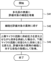
- the following method can be considered as a method for evaluating the permeability of the porous film.
- a liquid containing a phosphor is contained in the first flow path
- a liquid containing no phosphor is contained in the second flow path
- the liquid is diffused in the liquid
- the second flow is permeated through the porous film.
- a method of monitoring the amount of light emitted from the phosphor leaking into the road can be considered.
- a large amount of time for example, about 60 minutes
- the technique of the present disclosure has been made in view of the above points, and one aspect is to evaluate the permeability of a porous membrane in a short time.
- the evaluation method according to the technique of the present disclosure is a method for evaluating the permeability of the porous membrane that separates the first flow path and the second flow path by supplying pressure to the liquid in the first flow path. It includes acquiring a change occurring in the liquid contained in the second flow path as an evaluation index of the permeability of the porous membrane.
- the evaluation method according to the technique of the present disclosure is a method for evaluating the permeability of the porous membrane inserted between the first flow path and the second flow path, and changes the supply pressure to the first flow path. This includes acquiring as an evaluation index of the permeability of the porous membrane the change that occurs in the liquid contained in the second flow path when the liquid is supplied while the liquid is being supplied.
- the change with time of the flow rate of the liquid passing through the second flow path may be acquired as an evaluation index.
- the liquid supplied to the first flow path may include a phosphor, and the change with time of the amount of light radiated from the phosphor contained in the liquid flowing through the second flow path may be acquired as an evaluation index.
- the liquid supplied to the first flow path may contain a specific component, and the change over time in the concentration of the specific component contained in the liquid flowing through the second flow path may be acquired as an evaluation index.
- the cell evaluation method according to the technique of the present disclosure is a cell evaluation method using the above-mentioned method for evaluating the permeability of a porous membrane, and is an evaluation obtained in a state where cells to be evaluated are cultured on the surface of the porous membrane.
- the index includes obtaining the index as an index of the performance of the cell to be evaluated to prevent the liquid supplied to the first flow path from leaking to the second flow path.
- the method for evaluating a drug according to the technique of the present disclosure is a method for evaluating a drug using the above-mentioned method for evaluating the permeability of a porous membrane, in which cells are cultured on the surface of the porous membrane and the cells are used as the drug to be evaluated.
- the evaluation index obtained after exposure is included as an index of toxicity of the drug to be evaluated to cells.
- a microfluidic device having a first flow path and a second flow path may be used.
- FIG. 4A It is a perspective view which shows an example of the structure of the microfluidic device which concerns on embodiment of the technique of this disclosure. It is an exploded perspective view of the microfluidic device which concerns on embodiment of the technique of this disclosure. It is a schematic diagram which shows a part of the cross section along line 3-3 in FIG. It is a top view which shows an example of the structure of the porous membrane which concerns on embodiment of the technique of this disclosure. It is sectional drawing along the line 4B-4B in FIG. 4A. It is a figure which shows an example of the structure of the evaluation system which concerns on embodiment of the technique of this disclosure. It is a figure which showed typically the flow path structure in the evaluation system which concerns on embodiment of the technique of this disclosure.
- It is a flow path block diagram which shows an example of the cell evaluation method which concerns on other embodiment of the technique of this disclosure. It is a flowchart which shows an example of the cell evaluation method which concerns on other embodiment of the technique of this disclosure. It is a flowchart which shows an example of the evaluation method of the drug which concerns on other embodiment of the technique of this disclosure. It is a figure which shows an example of the result of having evaluated the toxicity of a drug using the evaluation method which concerns on embodiment of the technique of this disclosure.
- FIG. 1 is a perspective view showing an example of the configuration of the microfluidic device 110 used for evaluating the permeability of the porous membrane according to the embodiment of the technique of the present disclosure
- FIG. 2 is an exploded perspective view of the microfluidic device 110. is there.
- FIG. 3 is a schematic view showing a part of a cross section taken along the line 3-3 in FIG.
- the microfluidic device 110 has a cavity unit 16 composed of an upper cavity member 12 and a lower cavity member 14 facing each other as a pair of cavity members laminated in the thickness direction.
- the upper cavity member 12 and the lower cavity member 14 are made of a flexible material such as PDMS (polydimethylsiloxane) as an example.
- PDMS polydimethylsiloxane
- the materials constituting the upper cavity member 12 and the lower cavity member 14 include epoxy-based resin, urethane-based resin, styrene-based thermoplastic elastomer, olefin-based thermoplastic elastomer, acrylic-based thermoplastic elastomer, and polyvinyl. It is possible to use alcohol or the like.
- a recess 26 defining the lower microchannel 24 is formed on the upper surface of the lower cavity member 14, that is, the surface 14A facing the upper cavity member 12.
- the lower microchannel 24 is an example of a second channel in the technique of the present disclosure.
- the recess 26 has an inflow port 26A, an outflow port 26B, and a flow path portion 26C communicating the inflow port 26A and the outflow port 26B.
- a recess 20 defining the upper microchannel 18 is formed on the lower surface of the upper cavity member 12, that is, the surface 12A facing the lower cavity member 14.
- the upper microchannel 18 is an example of a first channel in the technique of the present disclosure.
- the recess 20 has an inflow port 20A, an outflow port 20B, and a flow path portion 20C communicating the inflow port 20A and the outflow port 20B.
- the upper cavity member 12 is provided with through holes 22A and 22B that penetrate the upper cavity member 12 in the thickness direction. The lower ends of the through holes 22A and 22B communicate with the inflow port 20A and the outflow port 20B, respectively.
- the inflow port 26A and the outflow port 26B of the lower cavity member 14 are provided at positions that do not overlap with the inflow port 20A and the outflow port 20B of the upper cavity member 12 in a plan view.
- the flow path portion 26C of the lower cavity member 14 is provided at a position where it overlaps with the flow path portion 20C of the upper cavity member 12 in a plan view.
- the upper cavity member 12 is provided with through holes 28A and 28B which penetrate the upper cavity member 12 in the thickness direction and whose lower end communicates with the inflow port 26A and the outflow port 26B of the lower cavity member 14, respectively.
- recesses 29 are provided at positions where spacers 46 are arranged.
- a porous membrane 30 is arranged between the facing surfaces 12A and 14A of the upper cavity member 12 and the lower cavity member 14.
- the upper surface 30A and the lower surface 30B of the porous membrane 30 cover the flow paths 20C and 26C of the upper micro flow path 18 and the lower micro flow path 24, and separate the upper micro flow path 18 and the lower micro flow path 24. .. That is, the lower microchannel 24 and the upper microchannel 18 are adjacent to each other with the porous membrane 30 interposed therebetween.
- the upper surface 30A of the porous membrane 30 defines the upper microchannel 18 together with the recess 20 of the upper cavity member 12, and the lower surface 30B of the porous membrane 30 is lower together with the recess 26 of the lower cavity member 14.
- the microchannel 24 is defined.
- the porous membrane 30 is composed of a hydrophobic polymer that is soluble in a hydrophobic organic solvent.
- the hydrophobic organic solvent is a liquid having a solubility in water at 25 ° C. of 10 (g / 100 g water) or less.
- examples of the hydrophobic polymer include polystyrene, polyacrylate, polymethacrylate and the like.
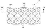
- FIG. 4A is a plan view showing an example of the configuration of the porous membrane 30.
- FIG. 4B is a cross-sectional view taken along the line 4B-4B in FIG. 4A.
- a plurality of in-membrane spaces 32 penetrating in the thickness direction are formed in the porous membrane 30, and openings 32A of the in-membrane space 32 are provided on both upper surfaces 30A and lower surfaces 30B of the porous membrane 30. ..
- the opening 32A is circular in a plan view.
- the openings 32A are provided apart from each other, and a flat portion 34 extends between the adjacent openings 32A.
- the opening 32A is not limited to a circular shape, but may be a polygonal shape or an elliptical shape.
- the plurality of openings 32A are arranged in a honeycomb shape.
- six openings 32A are equally arranged around an arbitrary opening 32A (excluding the opening 32A at the edge of the film), and the center of the six openings 32A is a regular hexagon.
- the term "equal distribution” as used herein does not necessarily mean that the openings are accurately arranged at a central angle of 60 °, and the six surrounding openings 32A are arranged at substantially equal intervals with respect to the opening 32A located at the center. It suffices if it is done.
- the "center of the opening 32A" means the center of the opening 32A in a plan view.
- the in-membrane space 32 of the porous membrane 30 has a spherical segment shape in which the upper end and the lower end of the sphere are cut off.
- the sphere referred to here does not have to be a true sphere, and a degree of distortion that is generally recognized as a sphere is allowed.
- the in-membrane spaces 32 adjacent to each other have a horizontal communication structure in which communication holes 36 communicate with each other inside the porous membrane 30.
- the horizontal communication structure refers to a space structure in which adjacent in-membrane spaces 32 communicate with each other inside the porous membrane 30.
- the term "horizontal" as used herein means a plane direction orthogonal to the vertical direction when the thickness direction of the porous membrane 30 is vertical.
- the arbitrary in-membrane space 32 communicates with all of the six in-membrane spaces 32 evenly distributed around the perforated membrane 30.
- the in-membrane space 32 may have a barrel shape, a cylindrical shape, a polygonal column shape, or the like, and the communication hole 36 may be a tubular void connecting adjacent in-membrane spaces 32. ..
- the average opening diameter of the opening 32A is preferably 1 ⁇ m or more and 200 ⁇ m or less. By setting the average opening diameter of the opening 32A to 1 ⁇ m or more, it is easy to form a laterally communicating structure of the in-membrane space 32. Further, by setting the average opening diameter of the openings 32A to 200 ⁇ m or less, it is easy to maintain a honeycomb-like arrangement without fusing the adjacent openings 32A.
- the average opening diameter means the average value of the diameters of the plurality of openings 32A on the surface of the porous membrane 30.
- the average aperture diameter can be, for example, an average value obtained by observing the surface of the porous membrane 30 under a microscope and measuring the diameters of a considerable number of openings 32A.
- the porosity of the porous membrane 30 is preferably 40% or more and 90% or less. By setting the porosity of the porous membrane 30 to 40% or more, it is easy to form a laterally communicating structure of the in-membrane space 32. By setting the porosity of the porous membrane 30 to 90% or less, it becomes easy to maintain the shape of the porous membrane 30, and the strength does not decrease and it becomes difficult to tear.
- the porosity refers to the ratio of the volume of the in-membrane space 32 to the volume of the porous membrane 30.
- This void ratio was determined by, for example, observing the cross section of the porous membrane 30 under a microscope and estimating that the observed in-membrane space 32 was a spherical segment shape in which the upper and lower sides and the six sides were cut off in a circular shape. It can be obtained as a percentage obtained by dividing the volume of the plurality of in-membrane spaces 32 by the volume of the porous membrane 30 in which the in-membrane spaces 32 are present.
- the film thickness of the porous membrane 30 is preferably 0.5 ⁇ m or more and 100 ⁇ m or less.
- the numerical value of this film thickness is the aspect ratio between the opening diameter of the opening 32A and the height of the intramembrane space 32 (that is, the value obtained by dividing the opening diameter of the opening 32A by the height of the intramembrane space 32). It is a numerical value derived from the fact that it is practically impossible to exceed 2.
- the film thickness is preferably 0.5 to 10 ⁇ m.
- the total film thickness of the porous films 30 is preferably 10 to 200 ⁇ m.
- the microfluidic device 110 has a pair of holding plates 38 as holding members for holding the cavity unit 16 in a compressed state in the thickness direction.
- the pair of holding plates 38 are provided separately from the cavity unit 16 at both ends of the cavity unit 16 in the thickness direction, that is, on the upper side of the upper cavity member 12 and on the lower side of the lower cavity member 14, and the upper cavity member 12 It is sized to cover the entire upper surface of the above and the entire lower surface of the lower cavity member 14.
- a plurality of (eight in this embodiment) bolt holes 40 penetrating in the thickness direction are formed at positions of the pair of holding plates 38 corresponding to each other. Further, in the holding plate 38 provided on the upper side of the upper cavity member 12, through holes 42A, 42B, 44A, 44B communicating with the through holes 22A, 22B, 28A, 28B of the upper cavity member 12, respectively, are formed. ing.
- inflow tubes 62A and 64A are connected to the through holes 42A and 44A, respectively, and outflow tubes 62B and 64B are connected to the through holes 42B and 44B, respectively.
- the various treatment solutions and cell suspensions flow into the upper microchannel 18 and the lower microchannel 24 through the inflow tubes 62A and 64A.
- Various solutions and cell suspensions that have passed through the upper microchannel 18 and the lower microchannel 24 flow out from the outflow tubes 62B and 64B.
- a plurality of (eight in this embodiment) spacers 46 that define the spacing between the holding plates 38 are provided on the outside of the recesses 29 of the cavity unit 16 between the pair of holding plates 38.
- the spacer 46 is a cylindrical member having an inner diameter substantially the same as the inner diameter of the bolt hole 40, and is arranged at a position corresponding to the bolt hole 40.
- the pair of holding plates 38 are joined to each other by a plurality of bolts 50 which are inserted into the bolt holes 40 and the spacer 46 and fixed by nuts 48. At this time, the upper cavity member 12 and the lower cavity member 14 are compressed and held by the pair of holding plates 38 with the porous membrane 30 sandwiched between them.
- FIG. 5 is a diagram showing an example of the configuration of the evaluation system 200 used for evaluating the permeability of the porous membrane according to the embodiment of the technique of the present disclosure.
- the evaluation system 200 includes a flow rate control device 120, a storage unit 130, and a flow rate sensor 140 in addition to the microfluidic device 110.
- the storage unit 130 stores the liquid 131 supplied to the upper microchannel 18 of the microfluidic device 110.
- the tip of the inflow tube 62A connected to the upper microchannel 18 is inserted into the liquid 131 stored in the storage unit 130.
- the flow rate control device 120 has a function of controlling the flow rate (volume per unit time) of the liquid 131 supplied to the upper micro flow path 18 of the microfluidic device 110.
- One end of the air supply tube 122 is connected to the exhaust port 121 of the flow control device 120, and the other end of the air supply tube 122 is connected to the gas introduction port 132 of the storage unit 130.
- the flow rate control device 120 controls the flow rate of the liquid 131 supplied to the upper micro flow path 18 by controlling the pressure of the gas discharged from the exhaust port 121 (hereinafter referred to as supply pressure).
- the supply pressure is a pressure on the liquid surface of the liquid 131 stored in the storage unit 130.
- the supply pressure can be arbitrarily set by the user, and the supply pressure can be continuously changed.
- ELVEFLOW registered trademark manufactured by ELVESYS can be used as the flow rate control device 120.
- the flow rate sensor 140 is connected to the outflow tube 64B connected to the lower micro flow path 24.
- the flow rate sensor 140 detects the flow rate of the liquid flowing through the lower micro flow path 24 and outputs the detected flow rate.
- the outflow tube 62B connected to the upper microchannel 18 and the inflow tube 64A connected to the lower microchannel 24 are each in a blocked state.
- FIG. 6 is a diagram schematically showing a flow path configuration in the evaluation system 200.
- FIG. 7 is a flowchart showing an example of a method for evaluating the permeability of the porous membrane 30 according to the embodiment of the technique of the present disclosure.
- the upper microchannel 18 and the lower microchannel 24 are each filled with a liquid (step S1).
- the flow rate control device 120 is operated.
- the supply pressure of the flow control device 120 is set so that it changes over time. That is, the liquid 131 is supplied to the upper micro flow path 18 while changing the supply pressure (step S2).
- the flow rate of the liquid 131 supplied from the storage unit 130 to the upper microchannel 18 changes.
- the liquid contained in the upper microchannel 18 permeates the porous membrane 30 and flows out to the lower microchannel 24. .. As a result, a liquid flow is generated in the lower microchannel 24.
- the flow rate of the liquid flowing through the lower microchannel 24 changes according to the supply pressure in the flow rate control device 120, and also depends on the permeability of the porous membrane 30.
- the flow rate sensor 140 acquires a change over time in the flow rate of the liquid flowing through the lower microchannel 24 as an evaluation index (step S3).
- FIG. 8 is a graph showing an example of the time transition of the supply pressure in the flow rate control device 120. As shown in FIG. 8, the supply pressure may be set to change linearly with time.
- FIG. 9 is a graph showing an example of the time transition of the flow rate of the liquid flowing through the lower microchannel 24 when the supply pressure is changed linearly with time.
- the solid line corresponds to the case where the permeability of the porous membrane 30 is relatively high
- the dotted line corresponds to the case where the permeability of the porous membrane 30 is relatively low.
- the rate of change (slope) of the flow rate of the liquid flowing through the lower microchannel 24 is higher than that when the permeability of the porous membrane 30 is relatively low. growing. Therefore, it is possible to evaluate the permeability of the porous membrane 30 by monitoring the flow rate of the liquid flowing through the lower microchannel 24.
- a graph showing the time transition of the flow rate as shown in FIG. 9 may be acquired.
- the rate of change (slope) of the flow rate of the liquid flowing through the lower microchannel 24 may be acquired as the time course of the flow rate of the liquid flowing through the lower microchannel 24.
- ⁇ Q / ⁇ t may be acquired as the rate of change (slope).
- the Q 1 / P 1 changes over time in the flow rate of liquid flowing under the microchannel 24 May be obtained as.
- the flow rates of the liquid flowing through the lower microchannel 24 at different supply pressures P 1 , P 2 , ..., P n are Q 1 , Q 2 , ..., Q n , respectively, Q 1
- the average value of / P 1 , Q 2 / P 2 , ..., Q n / P n may be obtained as a change over time in the flow rate of the liquid flowing through the lower microchannel 24.
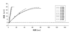
- FIG. 10 is a diagram showing an example of the result of evaluating the permeability of a plurality of types of porous membranes having different pore diameters or aperture ratios by using the evaluation method according to the embodiment of the technique of the present disclosure. That is, FIG. 10 shows the time transition of the flow rate of the liquid flowing through the lower microchannel 24 when the supply pressure is changed linearly with time for each of the plurality of types of porous membranes A to I. ing.
- the outline of the porous membranes A to I is shown in Table 1 below.
- the change in the flow rate with respect to time is non-linear because an unintended leak occurs in the flow path.
- the method for evaluating the permeability of the porous membrane is the lower microchannel 24 when a liquid is supplied to the upper microchannel 18 while changing the supply pressure.
- the change that occurs in the liquid contained in the porous membrane is acquired as an evaluation index of the permeability of the porous membrane.
- a time-dependent change in the flow rate of the liquid flowing through the lower microchannel 24 is acquired as "a change occurring in the liquid contained in the lower microchannel 24".
- a liquid containing a phosphor is contained in the upper microchannel 18 and a liquid containing no phosphor is contained in the lower microchannel 24.
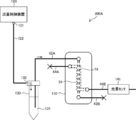
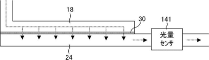
- FIG. 11 is a diagram showing an example of the configuration of the evaluation system 200A according to the second embodiment of the technique of the present disclosure.
- FIG. 12 is a diagram schematically showing a flow path configuration of the evaluation system 200A.
- the evaluation system 200A includes a light amount sensor 141 instead of the flow rate sensor 140 in the evaluation system 200 according to the first embodiment.
- FIG. 13 is a flowchart showing an example of a method for evaluating the permeability of the porous membrane 30 according to the second embodiment of the technique of the present disclosure.
- the upper microchannel 18 is filled with a liquid containing a phosphor (step S11).
- the lower microchannel 24 is filled with a liquid containing no phosphor (step S12).
- the flow rate control device 120 is operated.
- the supply pressure of the flow control device 120 is set so that it changes over time.
- the storage unit 130 contains a liquid 131 containing a phosphor. That is, the liquid 131 containing the phosphor is supplied to the upper microchannel 18 while changing the supply pressure (step S13). As the supply pressure changes, the flow rate of the liquid 131 supplied from the storage unit 130 to the upper microchannel 18 changes.
- the liquid 131 containing the phosphor is further supplied to the upper microchannel 18 filled with the liquid containing the phosphor in advance, so that the liquid containing the phosphor contained in the upper microchannel 18 forms the porous film 30. It permeates and flows out to the lower microchannel 24. As a result, a liquid flow due to the liquid containing the phosphor is generated in the lower microchannel 24.
- the liquid flowing through the lower microchannel 24 is irradiated with excitation light from a light source (not shown). As a result, light is emitted from the phosphor contained in the liquid flowing through the lower microchannel 24.
- the rate of change in the amount of light radiated from the phosphor contained in the liquid flowing through the lower microchannel 24 (hereinafter referred to as the amount of fluorescent light) changes according to the supply pressure in the flow rate control device 120, and is a porous film. It depends on the transparency of 30.
- the light amount sensor 141 acquires the change with time of the fluorescent light amount as an evaluation index (step S14).
- FIG. 14 is a graph showing an example of the time transition of the amount of fluorescent light when the supply pressure is changed linearly with time.
- the solid line corresponds to the case where the permeability of the porous membrane 30 is relatively high
- the dotted line corresponds to the case where the permeability of the porous membrane 30 is relatively low.
- a graph showing the time transition of the amount of fluorescent light as shown in FIG. 14 may be acquired.
- the rate of change (slope) of the amount of fluorescent light may be acquired as the change with time of the amount of fluorescent light.
- the amount of change in the amount of fluorescent light in the period ⁇ T is ⁇ L
- ⁇ L / ⁇ t may be acquired as the rate of change (slope).
- L 1 / P 1 may be acquired as a change over time in the amount of fluorescent light.
- L 1 , L 2 , ..., L n are L 1 , L 2 , ..., L n , respectively, L 1 / P 1 , L 2 / P 2 , ..., The average value of L n / P n may be acquired as a change over time in the amount of fluorescent light.
- FIG. 15 is a diagram showing an example of the configuration of the evaluation system 200B according to the third embodiment of the technique of the present disclosure.
- FIG. 16 is a diagram schematically showing a flow path configuration of the evaluation system 200B.
- the evaluation system 200B includes a concentration sensor 142 instead of the flow rate sensor 140 in the evaluation system 200 according to the first embodiment.
- FIG. 17 is a flowchart showing an example of a method for evaluating the permeability of the porous membrane 30 according to the third embodiment of the technique of the present disclosure.
- the upper microchannel 18 is filled with a liquid containing a specific component (step S21).
- the lower microchannel 24 is filled with a liquid containing no specific component (step S22).
- the flow rate control device 120 is operated.
- the supply pressure of the flow control device 120 is set so that it changes over time.
- the storage unit 130 contains a liquid 131 containing a specific component. That is, the liquid 131 containing the specific component is supplied to the upper microchannel 18 while changing the supply pressure (step S23). As the supply pressure changes, the flow rate of the liquid 131 supplied from the storage unit 130 to the upper microchannel 18 changes.
- the liquid containing the specific component contained in the upper microchannel 18 forms the porous membrane 30. It permeates and flows out to the lower microchannel 24. As a result, a liquid flow by a liquid containing a specific component is generated in the lower microchannel 24.
- the rate of change of the concentration of the specific component (hereinafter referred to as the specific component concentration) in the liquid flowing through the lower microchannel 24 changes according to the supply pressure in the flow rate control device 120, and also depends on the permeability of the porous membrane 30. It becomes a thing.
- the concentration sensor 142 acquires the change with time of the specific component concentration as an evaluation index (step S24).
- the specific component may be any substance that can be quantified, and examples thereof include dyes, conductive substances, enzymes, nanoparticles, substances containing radioisotopes, nucleic acids, and sugar chains. Most substances can be quantified by using techniques such as liquid chromatography.
- FIG. 18 is a graph showing an example of the time transition of the specific component concentration when the supply pressure is changed linearly with time.
- the solid line corresponds to the case where the permeability of the porous membrane 30 is relatively high
- the dotted line corresponds to the case where the permeability of the porous membrane 30 is relatively low.
- the rate of change (slope) of the specific component concentration is larger than when the permeability of the porous membrane 30 is relatively low. Therefore, it is possible to evaluate the permeability of the porous membrane 30 by monitoring the concentration of a specific component.
- a graph showing the time transition of the specific component concentration as shown in FIG. 18 may be acquired. Further, the rate of change (slope) of the specific component concentration may be acquired as the change with time of the specific component concentration. Specifically, when the amount of change in the specific component concentration in the period ⁇ T is ⁇ C, ⁇ C / ⁇ t may be acquired as the rate of change (slope). Further, when the supply pressure is P 1 and the specific component concentration is C 1 , C 1 / P 1 may be acquired as the change over time of the specific component concentration.
- the evaluation method according to the present embodiment it is possible to evaluate the permeability of the porous membrane in a short time as in the evaluation method according to the first embodiment.
- [Fourth Embodiment] 19 and 20, respectively, are a flow path configuration diagram and a flowchart showing an example of a cell evaluation method according to a fourth embodiment of the technique of the present disclosure.
- the cell evaluation method includes culturing the cells to be evaluated on the surface of the porous membrane 30 of the microfluidic device 110 (step S31).
- endothelial cells 301 may be cultured on the surface of the porous membrane 30 on the upper microchannel 18 side
- smooth muscle cells 302 may be cultured on the surface of the porous membrane 30 on the lower microchannel 24 side.
- a structure simulating a blood vessel (artery) can be formed in the microfluidic device 110.
- the endothelial cells 301 and smooth muscle cells 302 are cultured in a state of being immersed in the culture medium contained in the upper microchannel 18 and the lower microchannel 24.
- the cells to be evaluated may be cultured only on one surface of the porous membrane 30.
- the evaluation index of the permeability of the porous membrane 30 is used as the evaluation target cell cultured on the surface of the porous membrane 30.
- the cell barrier property means the ability of the cells to be evaluated cultured on the surface of the porous membrane 30 to prevent leakage of the liquid supplied to the upper microchannel 18 to the lower microchannel 24. To do.
- the barrier property of the cells suppresses the outflow of liquid from the upper microchannel 18 to the lower microchannel 24.
- the evaluation index of the permeability of the porous membrane 30 according to the first to third embodiments described above can be used as an index of the barrier property of the cells to be evaluated cultured on the surface of the porous membrane 30. ..
- the evaluation index of the permeability of the porous membrane 30 according to the first embodiment is used as an index of the barrier property of the cells to be evaluated
- the liquid is supplied to the upper microchannel 18 while changing the supply pressure.
- the time course of the flow rate of the liquid flowing through the lower microchannel is used as an index of the barrier property of the cells to be evaluated.
- a liquid containing a phosphor is contained in the upper microchannel 18 and a liquid containing no phosphor is contained in the lower microchannel 24, and the liquid is contained.
- the barrier property of cells can be evaluated in a short time as compared with the method of monitoring the amount of light emitted from the phosphor that diffuses the cells and leaks to the lower microchannel 24 through the porous membrane. It will be possible.
- FIG. 21 is a flowchart showing an example of a drug evaluation method according to a fifth embodiment of the technique of the present disclosure.
- the method for evaluating a drug includes culturing cells on the surface of the porous membrane 30 of the microfluidic device 110 (step S41). For example, as shown in FIG. 19, endothelial cells 301 are cultured on the surface of the porous membrane 30 on the upper microchannel 18 side, and smooth muscle cells 302 are cultured on the surface of the porous membrane 30 on the lower microchannel 24 side. You may. Thereby, a structure simulating a blood vessel (artery) can be formed in the microfluidic device 110. The cells to be evaluated may be cultured only on one surface of the porous membrane 30.
- the method for evaluating a drug according to the present embodiment includes exposing cells cultured on the surface of the porous membrane 30 to the drug to be evaluated (step S42). That is, a liquid containing the drug to be evaluated is supplied to each of the upper microchannel 18 and the lower microchannel 24.
- an evaluation index for the permeability of the porous membrane 30 according to any one of the first to third embodiments described above is obtained as an index for toxicity of the drug to be evaluated to cells. Including that. That is, when a liquid is supplied to the upper microchannel 18 while changing the supply pressure, the change that occurs in the liquid contained in the lower microchannel 24 is acquired as an index of toxicity of the drug to be evaluated to cells. (Step S43).
- the barrier property of these cells suppresses the outflow of liquid from the upper microchannel 18 to the lower microchannel 24.
- the drug to be evaluated has toxicity to the cells cultured on the surface of the porous membrane 30, when the cells become abnormal and the barrier property of the cells is lowered, the upper microchannel 18 is transferred to the lower microchannel 24. Liquid outflow increases. Therefore, the evaluation index of the permeability of the porous membrane 30 according to the first to third embodiments described above can be used as an index of toxicity of the drug to be evaluated to cells.
- the liquid is supplied to the upper microchannel 18 while changing the supply pressure.
- the change over time in the flow rate of the liquid flowing through the lower microchannel is obtained as an index of toxicity of the drug to be evaluated to cells.
- FIG. 22 is a diagram showing an example of the result of evaluating the toxicity of a drug using the evaluation method according to the present embodiment. That is, FIG. 22 shows the time transition of the flow rate of the liquid flowing through the lower microchannel 24 when the supply pressure is changed linearly with time for each of the liquids A to E to be evaluated. ing. The outline of the liquids A to E is shown in Table 2 below.
- Liquid A and Liquid B are basal media to which DMSO (dimethyl sulfoxide) as a solvent is added, and cytochalasin having a concentration of 50 ⁇ g / ml, which is a drug to be evaluated, is contained.
- Liquid C and liquid D are basal media to which DMSO as a solvent is added, and do not contain a drug to be evaluated.
- Liquid E contains basal medium and does not contain DMSO or the agent to be evaluated.
- Endothelial cells 301 were cultured on the surface of the porous membrane 30 on the upper microchannel 18 side, and smooth muscle cells 302 were cultured on the surface of the porous membrane 30 on the lower microchannel 24 side.
- Millipore 0.4 ⁇ m pore diameter 0.4 ⁇ m
- the rate of change (inclination) of the flow rate of the liquid flowing through the lower microchannel 24 is determined by Vehicle (liquid C, liquid D) and Control (liquid E). ) Is significantly larger than that. This indicates that the cytochalasins contained in Liquid A and Liquid B are toxic to endothelial cells 301 and smooth muscle cells 302.
- a liquid containing a phosphor is contained in the upper microchannel 18 and a liquid containing no phosphor is contained in the lower microchannel 24, and the liquid is contained.
Abstract
Description

FIG. 10 is a diagram showing an example of the result of evaluating the permeability of a plurality of types of porous membranes having different pore diameters or aperture ratios by using the evaluation method according to the embodiment of the technique of the present disclosure. That is, FIG. 10 shows the time transition of the flow rate of the liquid flowing through the
図11は、本開示の技術の第2の実施形態に係る評価システム200Aの構成の一例を示す図である。図12は、評価システム200Aの流路構成を模式的に示した図である。評価システム200Aは、第1の実施形態に係る評価システム200における流量センサ140に代えて光量センサ141を備えている。 [Second Embodiment]
FIG. 11 is a diagram showing an example of the configuration of the
図15は、本開示の技術の第3の実施形態に係る評価システム200Bの構成の一例を示す図である。図16は、評価システム200Bの流路構成を模式的に示した図である。評価システム200Bは、第1の実施形態に係る評価システム200における流量センサ140に代えて濃度センサ142を備えている。 [Third Embodiment]
FIG. 15 is a diagram showing an example of the configuration of the
図19及び図20は、それぞれ、本開示の技術の第4の実施形態に係る細胞の評価方法の一例を示す流路構成図及びフローチャートである。 [Fourth Embodiment]
19 and 20, respectively, are a flow path configuration diagram and a flowchart showing an example of a cell evaluation method according to a fourth embodiment of the technique of the present disclosure.
図21は、本開示の技術の第5の実施形態に係る薬剤の評価方法の一例を示すフローチャートである。 [Fifth Embodiment]
FIG. 21 is a flowchart showing an example of a drug evaluation method according to a fifth embodiment of the technique of the present disclosure.

FIG. 22 is a diagram showing an example of the result of evaluating the toxicity of a drug using the evaluation method according to the present embodiment. That is, FIG. 22 shows the time transition of the flow rate of the liquid flowing through the
Claims (8)
- 第1の流路と第2の流路とを隔てる多孔膜の透過性の評価方法であって、
前記第1の流路内の液体に圧力を供給し、前記第2の流路に収容された液体に生じる変化を前記多孔膜の透過性の評価指標として取得する評価方法。 A method for evaluating the permeability of a porous membrane that separates a first flow path and a second flow path.
An evaluation method in which pressure is supplied to the liquid in the first flow path and changes occurring in the liquid contained in the second flow path are acquired as an evaluation index of the permeability of the porous membrane. - 第1の流路と第2の流路との間に挿入された多孔膜の透過性の評価方法であって、
前記第1の流路に供給圧力を変化させながら液体を供給した場合の、前記第2の流路に収容された液体に生じる変化を前記多孔膜の透過性の評価指標として取得する
評価方法。 A method for evaluating the permeability of a porous membrane inserted between a first flow path and a second flow path.
An evaluation method for acquiring as an evaluation index of the permeability of the porous membrane the change that occurs in the liquid contained in the second flow path when the liquid is supplied to the first flow path while changing the supply pressure. - 前記第2の流路を通過する液体の流量の経時変化を前記評価指標として取得する
請求項1または請求項2に記載の評価方法。 The evaluation method according to claim 1 or 2, wherein the change with time of the flow rate of the liquid passing through the second flow path is acquired as the evaluation index. - 前記第1の流路に供給される液体に蛍光体を含め、
前記第2の流路を流れる液体に含まれる蛍光体から放射される光量の経時変化を前記評価指標として取得する
請求項1または請求項2に記載の評価方法。 A phosphor is contained in the liquid supplied to the first flow path, and the liquid is contained.
The evaluation method according to claim 1 or 2, wherein the change with time of the amount of light radiated from the phosphor contained in the liquid flowing through the second flow path is acquired as the evaluation index. - 前記第1の流路に供給される液体に特定成分を含め、
前記第2の流路を流れる液体に含まれる前記特定成分の濃度の経時変化を前記評価指標として取得する
請求項1または請求項2に記載の評価方法。 The liquid supplied to the first flow path contains a specific component,
The evaluation method according to claim 1 or 2, wherein the change with time of the concentration of the specific component contained in the liquid flowing through the second flow path is acquired as the evaluation index. - 請求項1から請求項5のいずれか1項に記載の評価方法を用いた細胞の評価方法であって、
前記多孔膜の表面に評価対象の細胞を培養した状態において取得した前記評価指標を、前記評価対象の細胞が、前記第1の流路に供給される液体の前記第2の流路への漏洩を阻止する性能の指標として取得する
評価方法。 A cell evaluation method using the evaluation method according to any one of claims 1 to 5.
The evaluation index obtained by culturing the cells to be evaluated on the surface of the porous membrane is leaked to the second flow path of the liquid supplied to the first flow path by the cells to be evaluated. Evaluation method obtained as an index of performance to prevent. - 請求項1から請求項5のいずれか1項に記載の評価方法を用いた薬剤の評価方法であって、
前記多孔膜の表面に細胞を培養し、前記細胞を評価対象の薬剤に晒した後に取得した前記評価指標を、前記評価対象の薬剤の前記細胞に対する毒性の指標として取得する
評価方法。 A method for evaluating a drug using the evaluation method according to any one of claims 1 to 5.
An evaluation method in which cells are cultured on the surface of the porous membrane, the cells are exposed to a drug to be evaluated, and then the evaluation index obtained is obtained as an index of toxicity of the drug to be evaluated to the cells. - 前記第1の流路及び前記第2の流路を有するマイクロ流体デバイスを用いる
請求項1から請求項6のいずれか1項に記載の評価方法。 The evaluation method according to any one of claims 1 to 6, wherein a microfluidic device having the first flow path and the second flow path is used.
Priority Applications (3)
| Application Number | Priority Date | Filing Date | Title |
|---|---|---|---|
| JP2021546501A JP7071597B2 (en) | 2019-09-18 | 2020-05-12 | Permeability evaluation method of porous membrane, cell evaluation method and drug evaluation method |
| EP20865968.0A EP4016047A4 (en) | 2019-09-18 | 2020-05-12 | Method for evaluating permeability of porous film, method for evaluating cell and method for evaluating drug |
| US17/693,433 US11453904B2 (en) | 2019-09-18 | 2022-03-14 | Evaluation method for permeability of porous membrane, cell evaluation method, and drug evaluation method |
Applications Claiming Priority (2)
| Application Number | Priority Date | Filing Date | Title |
|---|---|---|---|
| JP2019-169806 | 2019-09-18 | ||
| JP2019169806 | 2019-09-18 |
Related Child Applications (1)
| Application Number | Title | Priority Date | Filing Date |
|---|---|---|---|
| US17/693,433 Continuation US11453904B2 (en) | 2019-09-18 | 2022-03-14 | Evaluation method for permeability of porous membrane, cell evaluation method, and drug evaluation method |
Publications (1)
| Publication Number | Publication Date |
|---|---|
| WO2021053877A1 true WO2021053877A1 (en) | 2021-03-25 |
Family
ID=74883732
Family Applications (1)
| Application Number | Title | Priority Date | Filing Date |
|---|---|---|---|
| PCT/JP2020/018941 WO2021053877A1 (en) | 2019-09-18 | 2020-05-12 | Method for evaluating permeability of porous film, method for evaluating cell and method for evaluating drug |
Country Status (4)
| Country | Link |
|---|---|
| US (1) | US11453904B2 (en) |
| EP (1) | EP4016047A4 (en) |
| JP (1) | JP7071597B2 (en) |
| WO (1) | WO2021053877A1 (en) |
Citations (8)
| Publication number | Priority date | Publication date | Assignee | Title |
|---|---|---|---|---|
| JPS61175547A (en) * | 1985-01-30 | 1986-08-07 | Nippon Felt Kk | Pressured water passage tester |
| JPH01134244U (en) * | 1988-03-09 | 1989-09-13 | ||
| JPH08101212A (en) | 1994-09-30 | 1996-04-16 | New Oji Paper Co Ltd | Continuous measuring apparatus of liquid sample |
| JP2010207143A (en) | 2009-03-10 | 2010-09-24 | Okayama Univ | Device and method for cell observation |
| JP2013512448A (en) * | 2009-12-01 | 2013-04-11 | ヘルス プロテクション エージェンシー | Analysis method and apparatus |
| JP2013167645A (en) * | 2006-04-19 | 2013-08-29 | Gore Enterprise Holdings Inc | Functional porous substrate for attaching biomolecule |
| JP2016090381A (en) * | 2014-11-05 | 2016-05-23 | 株式会社Ube科学分析センター | Transmission quantity measuring method and transmission quantity measuring apparatus |
| JP2019169806A (en) | 2018-03-22 | 2019-10-03 | ヤマハ株式会社 | Control device, communication relay device, communication system, and communication control method |
Family Cites Families (4)
| Publication number | Priority date | Publication date | Assignee | Title |
|---|---|---|---|---|
| ITPI20060108A1 (en) * | 2006-09-19 | 2008-03-20 | Extrasolution S R L | METHOD AND DEVICE TO MEASURE THE PERMEABILITY OF GAS THROUGH THIN FILM OR CONTAINER WALLS |
| US20180356399A1 (en) * | 2017-06-09 | 2018-12-13 | Fujifilm Corporation | Blood vessel model |
| JP6892965B2 (en) * | 2018-02-26 | 2021-06-23 | 富士フイルム株式会社 | Channel device |
| US20210041339A1 (en) * | 2019-08-08 | 2021-02-11 | Rutgers, The State University Of New Jersey | Methods for detection of the permeation of chemical warfare agents through membranes |
-
2020
- 2020-05-12 EP EP20865968.0A patent/EP4016047A4/en active Pending
- 2020-05-12 WO PCT/JP2020/018941 patent/WO2021053877A1/en active Application Filing
- 2020-05-12 JP JP2021546501A patent/JP7071597B2/en active Active
-
2022
- 2022-03-14 US US17/693,433 patent/US11453904B2/en active Active
Patent Citations (8)
| Publication number | Priority date | Publication date | Assignee | Title |
|---|---|---|---|---|
| JPS61175547A (en) * | 1985-01-30 | 1986-08-07 | Nippon Felt Kk | Pressured water passage tester |
| JPH01134244U (en) * | 1988-03-09 | 1989-09-13 | ||
| JPH08101212A (en) | 1994-09-30 | 1996-04-16 | New Oji Paper Co Ltd | Continuous measuring apparatus of liquid sample |
| JP2013167645A (en) * | 2006-04-19 | 2013-08-29 | Gore Enterprise Holdings Inc | Functional porous substrate for attaching biomolecule |
| JP2010207143A (en) | 2009-03-10 | 2010-09-24 | Okayama Univ | Device and method for cell observation |
| JP2013512448A (en) * | 2009-12-01 | 2013-04-11 | ヘルス プロテクション エージェンシー | Analysis method and apparatus |
| JP2016090381A (en) * | 2014-11-05 | 2016-05-23 | 株式会社Ube科学分析センター | Transmission quantity measuring method and transmission quantity measuring apparatus |
| JP2019169806A (en) | 2018-03-22 | 2019-10-03 | ヤマハ株式会社 | Control device, communication relay device, communication system, and communication control method |
Non-Patent Citations (1)
| Title |
|---|
| See also references of EP4016047A4 |
Also Published As
| Publication number | Publication date |
|---|---|
| JPWO2021053877A1 (en) | 2021-03-25 |
| EP4016047A1 (en) | 2022-06-22 |
| US20220195488A1 (en) | 2022-06-23 |
| US11453904B2 (en) | 2022-09-27 |
| JP7071597B2 (en) | 2022-05-19 |
| EP4016047A4 (en) | 2022-10-05 |
Similar Documents
| Publication | Publication Date | Title |
|---|---|---|
| WO2005059088B1 (en) | Cultured cell and method and apparatus for cell culture | |
| EP2411501B1 (en) | Apparatus for cell or tissue culture | |
| US8828332B2 (en) | Microfluidic capsule | |
| US20130122539A1 (en) | Microsieve for cells and particles filtration | |
| US9618500B2 (en) | Vascular model, method for producing said model and use thereof | |
| US11680241B2 (en) | Perfusion enabled bioreactors | |
| EP2358472B1 (en) | Fluidic culture device | |
| WO2017062609A1 (en) | Multiwell culture devices with perfusion and oxygen control | |
| JP7450269B2 (en) | Perfusable bioreactor | |
| JP2020521974A (en) | Blood vessel model | |
| US10094820B2 (en) | Method for handheld diagnostics and assays | |
| WO2021053877A1 (en) | Method for evaluating permeability of porous film, method for evaluating cell and method for evaluating drug | |
| Liu et al. | Microfluidic liquid-air dual-gradient chip for synergic effect bio-evaluation of air pollutant | |
| JP7011034B2 (en) | Microchannel device | |
| WO2009097099A1 (en) | Microfluidic device for cell culturing | |
| JP2015508669A (en) | Porous structure with independently controlled surface pattern | |
| CN220040471U (en) | Microfluidic chip | |
| US20230076661A1 (en) | Microfluidic device for analyzing a membrane | |
| US11975324B2 (en) | Microfluidic chip | |
| US20220340854A1 (en) | Millifluidic device for advanced cultures of biological agents | |
| US20210062128A1 (en) | In vitro tissue plate | |
| Yin et al. | A microfluidic device inspired by leaky tumor vessels for hematogenous metastasis mechanism research |
Legal Events
| Date | Code | Title | Description |
|---|---|---|---|
| 121 | Ep: the epo has been informed by wipo that ep was designated in this application |
Ref document number: 20865968 Country of ref document: EP Kind code of ref document: A1 |
|
| ENP | Entry into the national phase |
Ref document number: 2021546501 Country of ref document: JP Kind code of ref document: A |
|
| WWE | Wipo information: entry into national phase |
Ref document number: 2020865968 Country of ref document: EP |
|
| ENP | Entry into the national phase |
Ref document number: 2020865968 Country of ref document: EP Effective date: 20220317 |
|
| NENP | Non-entry into the national phase |
Ref country code: DE |