WO2021045120A1 - Air flow rate measurement device - Google Patents
Air flow rate measurement device Download PDFInfo
- Publication number
- WO2021045120A1 WO2021045120A1 PCT/JP2020/033289 JP2020033289W WO2021045120A1 WO 2021045120 A1 WO2021045120 A1 WO 2021045120A1 JP 2020033289 W JP2020033289 W JP 2020033289W WO 2021045120 A1 WO2021045120 A1 WO 2021045120A1
- Authority
- WO
- WIPO (PCT)
- Prior art keywords
- flow rate
- substrate
- flow path
- physical quantity
- housing
- Prior art date
Links
Images


Classifications
-
- G—PHYSICS
- G01—MEASURING; TESTING
- G01F—MEASURING VOLUME, VOLUME FLOW, MASS FLOW OR LIQUID LEVEL; METERING BY VOLUME
- G01F1/00—Measuring the volume flow or mass flow of fluid or fluent solid material wherein the fluid passes through a meter in a continuous flow
- G01F1/68—Measuring the volume flow or mass flow of fluid or fluent solid material wherein the fluid passes through a meter in a continuous flow by using thermal effects
- G01F1/684—Structural arrangements; Mounting of elements, e.g. in relation to fluid flow
- G01F1/688—Structural arrangements; Mounting of elements, e.g. in relation to fluid flow using a particular type of heating, cooling or sensing element
- G01F1/69—Structural arrangements; Mounting of elements, e.g. in relation to fluid flow using a particular type of heating, cooling or sensing element of resistive type
-
- G—PHYSICS
- G01—MEASURING; TESTING
- G01F—MEASURING VOLUME, VOLUME FLOW, MASS FLOW OR LIQUID LEVEL; METERING BY VOLUME
- G01F15/00—Details of, or accessories for, apparatus of groups G01F1/00 - G01F13/00 insofar as such details or appliances are not adapted to particular types of such apparatus
- G01F15/14—Casings, e.g. of special material
-
- G—PHYSICS
- G01—MEASURING; TESTING
- G01F—MEASURING VOLUME, VOLUME FLOW, MASS FLOW OR LIQUID LEVEL; METERING BY VOLUME
- G01F1/00—Measuring the volume flow or mass flow of fluid or fluent solid material wherein the fluid passes through a meter in a continuous flow
- G01F1/68—Measuring the volume flow or mass flow of fluid or fluent solid material wherein the fluid passes through a meter in a continuous flow by using thermal effects
- G01F1/684—Structural arrangements; Mounting of elements, e.g. in relation to fluid flow
-
- G—PHYSICS
- G01—MEASURING; TESTING
- G01K—MEASURING TEMPERATURE; MEASURING QUANTITY OF HEAT; THERMALLY-SENSITIVE ELEMENTS NOT OTHERWISE PROVIDED FOR
- G01K13/00—Thermometers specially adapted for specific purposes
- G01K13/02—Thermometers specially adapted for specific purposes for measuring temperature of moving fluids or granular materials capable of flow
Definitions
- This disclosure relates to an air flow rate measuring device.
- a sensor device including a flow rate sensor for measuring the flow rate of air and a temperature sensor for measuring the temperature of air is known.
- the flow rate sensor and temperature sensor of this sensor device are mounted on a printed circuit board.
- the printed circuit board Since the printed circuit board has a relatively thin plate shape, it is relatively difficult to process the printed circuit board into a shape that follows the streamline of air. Moreover, since the processing of the printed circuit board is relatively difficult, the dimensional accuracy of the printed circuit board is relatively low. According to the study of the present inventor, in the configuration of Patent Document 1, the flow of air flowing around the printed circuit board is liable to be disturbed and unstable due to the difficulty of processing in the printed circuit board and the low dimensional accuracy. Therefore, the measurement accuracy of the air flow rate by the flow rate sensor is lowered. It is an object of the present disclosure to provide an air flow rate measuring device that improves the measurement accuracy of the air flow rate.
- the air flow measuring device is connected to a base surface, a rear surface located on the side opposite to the base surface, and an end portion of the base surface and an end portion of the rear surface. And the second side surface connected to the end of the base surface opposite to the first side surface and the end of the rear surface opposite to the first side surface, and the flow rate flow path inlet formed on the base surface.
- a housing having a flow rate channel outlet formed on the rear surface and a flow rate channel communicating with the flow rate channel inlet and the flow rate channel outlet, a substrate arranged in the flow rate channel, and a flow rate flow rate.
- a flow rate detection unit that outputs a signal according to the flow rate of air flowing through the path, and the flow rate flow rate is a first inner surface located on the first side surface side of the flow rate flow path and a second flow rate flow path.
- the flow rate detection unit is mounted on the first inner surface side of the substrate, including the second inner surface located on the side surface side, and the distance from the substrate to the first inner surface in the thickness direction of the substrate is in the thickness direction of the substrate. It is larger than the distance from the substrate to the second inner surface in.
- FIG. 2 is a sectional view taken along line VV of FIG.
- FIG. 5 is an enlarged cross-sectional view taken along the line VI-VI of FIG.
- FIG. 2 is an enlarged sectional view taken along line VII-VII of FIG.
- FIG. 6 is an enlarged view of part VIII of FIG.
- FIG. 7 is an enlarged view of the IX portion of FIG.
- FIG. 11 is a cross-sectional view taken along the line XIV-XIV of FIG.
- FIG. 14 is an enlarged cross-sectional view taken along the line XV-XV of FIG.
- FIG. 3 is a cross-sectional view of a substrate and a substrate protection portion in the air flow rate measuring device of another embodiment.
- FIG. 3 is a cross-sectional view of a substrate and a substrate protection portion in the air flow rate measuring device of another embodiment. Sectional drawing of the air flow rate measuring apparatus of another embodiment.
- the air flow rate measuring device 21 is used, for example, in the intake system of the engine system 100 mounted on the vehicle.
- the engine system 100 includes an intake pipe 11, an air cleaner 12, an air flow rate measuring device 21, a throttle valve 13, a throttle sensor 14, an injector 15, an engine 16, an exhaust pipe 17, and electronic control.
- the device 18 is provided.
- the intake air is the air that is taken in.
- Exhaust is the air that is discharged.
- the intake pipe 11 is formed in a cylindrical shape and has an intake flow path 111. In the intake flow path 111, air sucked into the engine 16 flows.
- the air cleaner 12 is on the upstream side of the air flowing through the intake flow path 111, and is arranged in the intake pipe 11. Further, the air cleaner 12 removes foreign matter such as dust contained in the air flowing through the intake flow path 111.
- the air flow rate measuring device 21 is arranged on the downstream side of the air flowing through the intake flow path 111 with respect to the air cleaner 12. Then, the air flow rate measuring device 21 measures the flow rate of the air flowing through the intake flow path 111 between the air cleaner 12 and the throttle valve 13. Further, here, the air flow rate measuring device 21 measures the physical quantity of air flowing through the intake flow path 111. Details of the air flow rate measuring device 21 will be described later.
- the physical quantity of air flowing through the intake flow path 111 is a physical quantity different from the flow rate of air flowing through the intake flow path 111, and is the temperature of air as described later.
- the throttle valve 13 is arranged on the downstream side of the air flowing through the intake flow path 111 with respect to the air flow rate measuring device 21. Further, the throttle valve 13 is formed in a disk shape and is rotated by a motor (not shown). Then, the throttle valve 13 rotates to adjust the flow path area of the intake flow path 111 and adjust the flow rate of the air sucked into the engine 16.
- the throttle sensor 14 outputs a detection signal according to the opening degree of the throttle valve 13 to the electronic control device 18.
- the injector 15 injects fuel into the combustion chamber 164 of the engine 16 based on a signal from the electronic control device 18 described later.
- the engine 16 is an internal combustion engine, and burns a mixture of air flowing through the intake flow path 111 via the throttle valve 13 and fuel injected from the injector 15 in the combustion chamber 164. Due to the explosive force during combustion, the piston 162 of the engine 16 reciprocates in the cylinder 161.
- the engine 16 includes a cylinder 161, a piston 162, a cylinder head 163, a combustion chamber 164, an intake valve 165, an intake valve drive device 166, an exhaust valve 167, an exhaust valve drive device 168, and a spark plug 169.
- the cylinder 161 is formed in a tubular shape and houses the piston 162.
- the piston 162 reciprocates in the cylinder 161 along the axial direction of the cylinder 161.
- the cylinder head 163 is attached to the upper part of the cylinder 161. Further, the cylinder head 163 is connected to the intake pipe 11 and the exhaust pipe 17, and has a first cylinder flow path 181 and a second cylinder flow path 182.
- the first cylinder flow path 181 communicates with the intake flow path 111.
- the second cylinder flow path 182 communicates with the exhaust flow path 171 of the exhaust pipe 17, which will be described later.
- the combustion chamber 164 is partitioned by the cylinder 161 and the upper surface of the piston 162 and the lower surface of the cylinder head 163.
- the intake valve 165 is arranged in the first cylinder flow path 181 and is driven by the intake valve drive device 166 to open and close the combustion chamber 164 on the first cylinder flow path 181 side.
- the exhaust valve 167 is arranged in the second cylinder flow path 182, and is driven by the exhaust valve drive device 168 to open and close the combustion chamber 164 on the second cylinder flow path 182 side.
- the spark plug 169 is a mixture of air flowing through the intake flow path 111 via the throttle valve 13 in the combustion chamber 164 and fuel injected from the injector 15 based on a signal from the electronic control device 18 described later. Ignite.
- the exhaust pipe 17 is formed in a cylindrical shape and has an exhaust flow path 171.
- the gas burned in the combustion chamber 164 flows.
- the gas flowing through the exhaust flow path 171 is purified by an exhaust gas purifying device (not shown).
- the electronic control device 18 is mainly composed of a microcomputer or the like, and includes a CPU, a ROM, a RAM, an I / O, a bus line for connecting these configurations, and the like.
- the electronic control device 18 controls the opening degree of the throttle valve 13 based on the flow rate and physical quantity of air measured by the air flow rate measuring device 21, the opening degree of the throttle valve 13, and the like.
- the electronic control device 18 controls the fuel injection amount of the injector 15 and the ignition timing of the spark plug 169 based on the air flow rate and physical quantity measured by the air flow rate measuring device 21, the opening degree of the throttle valve 13, and the like. Take control.
- the electronic control device 18 is described as an ECU.
- the air flow rate measuring device 21 includes a housing 30, a substrate 76, a first substrate protection unit 771, a second substrate protection unit 772, a flow rate detection unit 75, and a physical quantity detection unit 81. ..
- the housing 30 is attached to a pipe extension portion 112 connected to the side surface of the intake pipe 11.
- the pipe extension portion 112 is formed in a cylindrical shape, and extends from the side surface of the intake pipe 11 in the direction from the radial inner side to the radial outer side of the intake pipe 11.
- the housing 30 has a holding portion 31, a sealing member 32, a lid portion 33, a connector cover 34, a terminal 35, and a bypass portion 40.
- the holding portion 31 is formed in a cylindrical shape, and is fixed to the pipe extension portion 112 by engaging the outer surface of the holding portion 31 and the inner surface of the pipe extension portion 112. Further, a groove to which the seal member 32 is attached is formed on the outer peripheral surface of the holding portion 31.
- the seal member 32 is, for example, an O-ring, which is attached to the groove of the holding portion 31, and closes the flow path in the pipe extension portion 112 by coming into contact with the pipe extension portion 112. As a result, the air flowing through the intake flow path 111 is suppressed from leaking to the outside via the pipe extension portion 112.
- the lid portion 33 is formed in a bottomed tubular shape, and is connected to the holding portion 31 in the axial direction of the holding portion 31. Further, the length of the lid portion 33 in the radial direction of the holding portion 31 is larger than the diameter of the pipe extension portion 112, and the lid portion 33 closes the hole of the pipe extension portion 112.
- the connector cover 34 is connected to the lid portion 33 and extends from the radial inside of the holding portion 31 to the radial outside. Further, the connector cover 34 is formed in a tubular shape and accommodates one end of the terminal 35.
- one end of the terminal 35 is housed in the connector cover 34. Further, although not shown, one end of the terminal 35 is connected to the electronic control device 18. Further, the central portion of the terminal 35 is housed in the lid portion 33 and the holding portion 31. The other end of the terminal 35 is connected to a substrate 76, which will be described later.
- the bypass portion 40 has a plurality of flow paths inside and is formed in a plate shape. Specifically, as shown in FIGS. 2 to 7, the bypass portion 40 has a housing base surface 41, a housing rear surface 42, a first housing side surface 51, and a second housing side surface 52. Further, the bypass portion 40 has a flow rate main flow rate inlet 431, a flow rate main flow rate outlet 432, a flow rate main flow rate 43, a flow rate sub-flow rate inlet 441, a flow rate sub-flow path 44, and a flow rate sub-flow rate outlet 442. Further, the bypass unit 40 includes a physical quantity flow path inlet 500, a physical quantity flow path 50, a first physical quantity flow path outlet 501, and a second physical quantity flow path outlet 502. In the following, for convenience, the holding portion 31 side of the housing 30 is on the upper side with respect to the bypass portion 40. Further, the side opposite to the holding portion 31 is set as the lower side with respect to the bypass portion 40.
- the housing base surface 41 is located on the upstream side of the air flowing through the intake flow path 111.
- the housing rear surface 42 is located on the side opposite to the housing base surface 41.
- the first housing side surface 51 corresponds to the first side surface and is connected to the end portion of the housing base surface 41 and the end portion of the housing rear surface 42.
- the second housing side surface 52 corresponds to the second side surface, and the end portion of the housing base surface 41 opposite to the first housing side surface 51 and the housing rear surface 42 opposite to the first housing side surface 51. It is connected to the end.
- the housing base surface 41, the housing rear surface 42, the first housing side surface 51, and the second housing side surface 52 are each formed in a stepped shape.
- the flow rate main flow path inlet 431 is formed on the housing base surface 41, and a part of the air flowing through the intake flow path 111 is introduced into the flow rate main flow path 43.
- the flow rate main flow path 43 communicates with the flow rate main flow rate inlet 431 and the flow rate main flow rate outlet 432.
- the flow rate main flow path outlet 432 is formed on the rear surface 42 of the housing.
- the flow rate sub-flow path inlet 441 is formed above the flow rate main flow path 43, and a part of the air flowing through the flow rate main flow path 43 is introduced into the flow rate sub-flow path 44.
- the flow rate sub-flow path 44 is a flow path branched from the middle of the flow rate main flow path 43, and has an introduction portion 443, a rear vertical portion 444, a folded-back portion 445, and a front vertical portion 446.
- the introduction portion 443 is connected to the flow rate sub-flow path inlet 441 and extends upward from the flow rate sub-flow rate inlet 441 and in the direction from the flow rate sub-flow path inlet 441 toward the rear surface 42 of the housing.
- the rear vertical portion 444 is connected to the end portion of the introduction portion 443 opposite to the flow rate sub-flow path inlet 441, and extends upward from the end portion of the introduction portion 443.
- the folded-back portion 445 is connected to the end portion of the rear vertical portion 444 opposite to the introduction portion 443, and extends from the end portion of the rear vertical portion 444 toward the housing base surface 41.
- the front vertical portion 446 is connected to the end portion of the folded-back portion 445 on the side opposite to the rear vertical portion 444, and extends downward from the end portion of the folded-back portion 445.
- the outlines of the flow rate sub-flow path inlet 441 and the second physical quantity flow path outlet 502 described later are omitted in order to clarify each flow path.
- the flow rate sub-flow path outlet 442 is formed on the side surface 51 of the first housing and the side surface 52 of the second housing, and communicates with the front vertical portion 446 and the outside of the housing 30. ..
- the folded-back portion 445 of the flow rate sub-flow path 44 includes the inner surface 61 of the first housing and the inner surface 62 of the second housing.
- the first housing inner surface 61 corresponds to the first inner surface, and is an inner surface located on the side surface 51 side of the first housing in the folded-back portion 445 of the flow rate sub-flow path 44.
- the inner surface 62 of the second housing corresponds to the second inner surface, and is an inner surface located on the side surface 52 side of the second housing in the folded-back portion 445 of the flow rate sub-flow path 44.
- one physical quantity flow path inlet 500 is formed on the housing base surface 41, and is located above the flow rate main flow path inlet 431. Further, the physical quantity flow path inlet 500 introduces a part of the air flowing through the intake flow path 111 into the physical quantity flow path 50.
- the physical quantity flow path 50 communicates with the physical quantity flow path inlet 500, the first physical quantity flow path outlet 501, and the second physical quantity flow path outlet 502.
- a plurality of first physical quantity flow path outlets 501 are formed on the side surface 51 of the first housing.
- a plurality of second physical quantity flow path outlets 502 are formed on the side surface 52 of the second housing.
- the physical quantity flow path inlet 500 includes the inner surface 63 of the third housing and the inner surface 64 of the fourth housing.
- the third housing inner surface 63 is located on the side surface 51 side of the first housing of the physical quantity flow path inlet 500, and is connected to the housing base surface 41.
- the fourth housing inner surface 64 corresponds to the third inner surface, is located on the side surface 52 side of the second housing of the physical quantity flow path inlet 500, and is connected to the housing base surface 41.
- the substrate 76 is, for example, a printed circuit board, which is electrically connected to the other end of the terminal 35. Further, as shown in FIG. 6, a part of the substrate 76 is arranged in the folded-back portion 445 of the flow rate sub-flow path 44, and faces the inner surface 61 of the first housing and the inner surface 62 of the second housing.
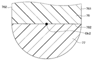
- the end portion of the substrate 76 on the inner surface 61 side of the first housing is referred to as the first substrate end portion 761.
- the end portion of the substrate 76 on the inner surface 62 side of the second housing is referred to as the second substrate end portion 762.
- the substrate 76 extends from the position of the folded portion 445 of the flow rate sub-flow path 44 to the position of the physical quantity flow path 50. Then, as shown in FIG. 7, a part of the substrate 76 is arranged in the physical quantity flow path 50. Further, as shown in FIGS. 3 and 7, the first substrate end portion 761 faces a plurality of first physical quantity flow path outlets 501. Further, as shown in FIGS. 4 and 7, the second substrate end portion 762 faces the plurality of second physical quantity flow path outlets 502.
- the first substrate protection portion 771 is formed, for example, by being resin-coated on a surface extending in the thickness direction of the substrate 76 arranged in the folded portion 445 of the flow rate sub-flow path 44. ..
- the first substrate protection portion 771 is formed on the upstream side and downstream side surfaces of the air flowing through the folded portion 445 of the flow rate sub-flow path 44 in the substrate 76, respectively.
- the first substrate protection portion 771 protects the substrate 76 by covering the surface extending in the thickness direction of the substrate 76.
- the outer edge of the first substrate protection portion 771 is curved in a cross section perpendicular to the longitudinal direction of the substrate 76.
- the first curvature center Ob1 of the outer edge of the first substrate protection portion 771 is located inside either the substrate 76 or the first substrate protection portion 771.
- the outer edge of the first substrate protection portion 771 is curved convexly.
- the outer edge of the first substrate protection portion 771 is formed in a semicircular shape, and the first curvature center Ob1 is the first boundary surface 781 which is the boundary between the substrate 76 and the first substrate protection portion 771. Is located in.
- the second substrate protection portion 772 is formed, for example, by being resin-coated on a surface extending in the thickness direction of the substrate 76 arranged in the physical quantity flow path 50.
- the second substrate protection unit 772 faces the physical quantity flow path inlet 500 and protects the substrate 76 by covering the surface extending in the thickness direction of the substrate 76.
- the outer edge of the second substrate protection portion 772 is curved in a cross section perpendicular to the longitudinal direction of the substrate 76. Further, in a cross section perpendicular to the longitudinal direction of the substrate 76, the second curvature center Ob2 of the outer edge of the second substrate protection portion 772 is located inside either the substrate 76 or the second substrate protection portion 772.
- the outer edge of the second substrate protection portion 772 is convexly curved.
- the outer edge of the second substrate protection portion 772 is formed in a semicircular shape, and the second curvature center Ob2 is the second boundary surface 782 which is the boundary between the substrate 76 and the second substrate protection portion 772. Is located in.
- the flow rate detection unit 75 is mounted on the substrate 76 arranged in the folded-back portion 445 of the flow rate sub-flow path 44. Further, the flow rate detecting unit 75 is mounted on the first substrate end portion 761 of the substrate 76 and faces the inner surface 61 of the first housing. Then, the flow rate detection unit 75 outputs a signal corresponding to the flow rate of the air flowing through the flow rate sub-flow path 44.
- the flow rate detection unit 75 includes a semiconductor including a heat generating element, a temperature sensitive element, and the like (not shown). This semiconductor conducts heat transfer with the air flowing through the flow rate sub-channel 44 by coming into contact with the air flowing through the flow rate sub-channel 44. This heat transfer changes the temperature of the semiconductor.
- This temperature change correlates with the flow rate of air flowing through the flow rate subchannel 44. Therefore, the flow rate detection unit 75 outputs a signal corresponding to this temperature change, so that a signal corresponding to the flow rate of the air flowing through the flow rate sub-flow path 44 is output.
- the output signal of the flow rate detection unit 75 is transmitted to the electronic control device 18 via the substrate 76 and the terminal 35.
- the distance from the inner surface 61 of the first housing in the thickness direction of the substrate 76 to the end portion 761 of the first substrate is the first distance L1.
- the distance from the inner surface 62 of the second housing in the thickness direction of the substrate 76 to the end portion 762 of the second substrate is defined as the second distance L2.
- the first distance L1 is larger than the second distance L2.
- the second distance L2 is larger than zero, and the second substrate end portion 762 is in non-contact with the inner surface 62 of the second housing.
- the physical quantity detection unit 81 is mounted on the second substrate end portion 762 of the substrate 76 and is arranged in the physical quantity flow path 50. Further, as shown in FIGS. 2 and 7, the physical quantity detection unit 81 faces the physical quantity flow path inlet 500. Further, as shown in FIGS. 4 and 7, the physical quantity detection unit 81 faces the second physical quantity flow path outlet 502 of one of the plurality of second physical quantity flow path outlets 502.
- the distance from the inner surface 63 of the third housing in the thickness direction of the substrate 76 to the first virtual line I1 is defined as the third distance L3.
- the first virtual line I1 is a virtual line that passes through the end portion 761 of the first substrate and extends in the width direction of the substrate 76.
- the third distance L3 corresponds to the distance from the inner surface 63 of the third housing in the thickness direction of the substrate 76 to the end portion 761 of the first substrate in the cross section perpendicular to the longitudinal direction of the substrate 76.
- the distance from the inner surface 64 of the fourth housing in the thickness direction of the substrate 76 to the second virtual line I2 is defined as the fourth distance L4.
- the second virtual line I2 is a virtual line that passes through the end portion 762 of the second substrate and extends in the width direction of the substrate 76.
- the fourth distance L4 corresponds to the distance from the inner surface 64 of the fourth housing in the thickness direction of the substrate 76 to the end portion 762 of the second substrate in the cross section perpendicular to the longitudinal direction of the substrate 76.
- the third distance L3 is larger than the fourth distance L4.
- the fourth distance L4 is larger than zero, and the physical quantity detecting unit 81 is less likely to come into contact with the inner surface 64 of the fourth housing.
- the physical quantity detection unit 81 outputs a signal according to the physical quantity of the air flowing through the physical quantity flow path 50.
- the physical quantity of the air flowing through the physical quantity flow path 50 is the temperature of the air flowing through the physical quantity flow path 50.
- the physical quantity detection unit 81 has, for example, a thermistor (not shown) and outputs a signal corresponding to the temperature of the air flowing through the physical quantity flow path 50. Further, since the physical quantity detection unit 81 is mounted on the board 76, the output signal of the physical quantity detection unit 81 is transmitted to the electronic control device 18 via the board 76 and the terminal 35.
- the air flow rate measuring device 21 is configured. Next, the measurement of the flow rate and the temperature by the air flow rate measuring device 21 will be described.
- a part of the air flowing through the intake flow path 111 flows through the flow rate main flow path inlet 431.
- the air flowing from the flow rate main flow path inlet 431 flows through the flow rate main flow path 43 toward the flow rate main flow rate outlet 432.
- a part of the air flowing through the flow rate main flow path 43 is discharged to the outside of the housing 30 via the flow rate main flow path outlet 432.
- a part of the air flowing through the flow rate main flow path 43 flows through the flow rate sub flow rate inlet 441.
- the air flowing from the flow rate sub-channel inlet 441 flows through the folded-back portion 445 via the introduction portion 443 and the rear vertical portion 444 of the flow rate sub-channel 44.
- a part of the air flowing through the folded-back portion 445 comes into contact with the flow rate detecting portion 75.
- the flow rate detection unit 75 outputs a signal corresponding to the flow rate of the air flowing through the flow rate sub-flow path 44 by coming into contact with the air.
- the output signal of the flow rate detection unit 75 is transmitted to the electronic control device 18 via the substrate 76 and the terminal 35.
- a part of the air flowing through the folded-back portion 445 is discharged to the outside of the housing 30 via the front vertical portion 446 of the flow rate sub-flow path 44 and the flow rate sub-flow path outlet 442.
- a part of the air flowing through the intake flow path 111 flows through the physical quantity flow path inlet 500.
- the air flowing from the physical quantity flow path inlet 500 flows through the physical quantity flow path 50.
- a part of the air flowing through the physical quantity flow path 50 comes into contact with the physical quantity detection unit 81.
- the physical quantity detection unit 81 outputs a signal corresponding to the temperature of the air flowing through the physical quantity flow path 50 by coming into contact with the air.
- the output signal of the physical quantity detection unit 81 is transmitted to the electronic control device 18 via the substrate 76 and the terminal 35. Further, the air flowing through the physical quantity flow path 50 is discharged to the outside of the housing 30 via the plurality of first physical quantity flow path outlets 501 and the second physical quantity flow path outlet 502.
- the air flow rate measuring device 21 measures the air flow rate and the air temperature.
- the accuracy of measuring the air flow rate is improved.
- the improvement of this measurement accuracy will be described.
- the flow rate detecting unit 75 is mounted on the end portion 761 of the first substrate and faces the inner surface 61 of the first housing. Further, the first distance L1 is larger than the second distance L2. Since the first distance L1 is larger than the second distance L2, the area of the air flow path between the inner surface 61 of the first housing and the end portion 761 of the first substrate is the inner surface 62 of the second housing and the end portion 762 of the second substrate. It is larger than the flow path area of the air flowing between and. Therefore, the flow rate of air flowing between the inner surface 61 of the first housing and the end portion 761 of the first substrate is larger than the flow rate of air flowing between the inner surface 62 of the second housing and the end portion 762 of the second substrate.
- the generation of this vortex suppresses the generation of other vortices, and the air flowing between the inner surface 61 of the first housing and the end portion 761 of the first substrate is less affected by the vortex. Therefore, the air flowing between the inner surface 61 of the first housing and the end portion 761 of the first substrate is less likely to be turbulent and becomes a stable flow. Therefore, in the air flow rate measuring device 21, the measurement accuracy of the air flow rate is improved.
- the air flow rate measuring device 21 also has the effects as described in [1]-[7] below.
- the second distance L2 is larger than zero, and the second substrate end portion 762 is in non-contact with the inner surface 62 of the second housing.
- heat is not conducted from the inner surface 62 of the second housing to the end portion 762 of the second substrate, so that the amount of heat conducted from the housing 30 to the substrate 76 is reduced. Therefore, the amount of heat conducted from the second substrate end portion 762 to the first substrate end portion 761 is reduced, so that the amount of heat conducted from the substrate 76 to the flow rate detection unit 75 is reduced. Therefore, the flow rate detection unit 75 is less likely to be affected by the heat from the substrate 76, and the measurement accuracy of the air flow rate is improved.
- the physical quantity detection unit 81 is mounted on the substrate 76.
- the air flow rate measuring device 21 can measure a physical quantity of air different from the air flow rate. Further, by mounting the flow rate detection unit 75 and the physical quantity detection unit 81 on the same substrate 76, the design of each part becomes relatively easy, so that the air flow rate measuring device 21 can be relatively easily manufactured. , The cost of the air flow rate measuring device 21 is reduced.
- the physical quantity detection unit 81 is mounted on the substrate 76 arranged in the physical quantity flow path 50, and measures the temperature of the air flowing through the physical quantity flow path 50. Since the physical quantity detection unit 81 is arranged in the physical quantity flow path 50 different from the flow rate sub-flow path 44, the physical quantity detection unit 81 does not disturb the air flowing through the folded portion 445 of the flow rate sub-flow path 44. Therefore, the air flowing between the inner surface 61 of the first housing and the end portion 761 of the first substrate is less likely to be turbulent and tends to be a stable flow. In the air flow rate measuring device 21, the measurement accuracy of the air flow rate is improved.
- the physical quantity detection unit 81 is mounted on the second substrate end portion 762 of the substrate 76. That is, the physical quantity detection unit 81 is mounted on the inner surface 64 side of the fourth housing of the substrate 76. Further, the fourth distance L4 is larger than zero, and the physical quantity detecting unit 81 is less likely to come into contact with the inner surface 64 of the fourth housing. As a result, heat conduction from the inner surface 64 of the fourth housing to the physical quantity detection unit 81 is less likely to occur, so that the amount of heat conducted from the housing 30 to the physical quantity detection unit 81 becomes smaller. Therefore, the physical quantity detecting unit 81 is less likely to be affected by the heat from the housing 30, so that the measurement accuracy of the air temperature is improved.
- the first substrate protection portion 771 extends in the thickness direction of the substrate 76 arranged in the folded portion 445 of the flow rate sub-flow path 44.
- the substrate 76 is protected by covering the surface.
- the second substrate protection unit 772 protects the substrate 76 by covering the surface extending in the thickness direction of the substrate 76 arranged in the physical quantity flow path 50. As a result, corrosion of the substrate 76 is suppressed.
- the first curvature center Ob1 of the outer edge of the first substrate protection portion 771 is located inside the substrate 76 and the first substrate protection portion 771. 1
- the outer edge of the substrate protection portion 771 is curved convexly. Since the outer edge of the first substrate protection portion 771 is convexly curved, the air flowing through the folded portion 445 of the flow rate sub-flow path 44 flows along the outer edge of the first substrate protection portion 771. As a result, the pressure loss of the air flowing through the folded portion 445 of the flow rate sub-flow path 44 is reduced, and the flow rate of the air flowing through the folded portion 445 of the flow rate sub-flow path 44 is suppressed from being reduced.
- the flow rate of the air flowing through the folded-back portion 445 of the flow rate sub-flow path 44 becomes relatively large, so that the flow rate detection unit 75 is easily cooled. Therefore, the flow rate detecting unit 75 is less affected by the heat transfer from the housing 30, and the measurement accuracy of the air flow rate is improved.
- the second curvature center Ob2 of the outer edge of the second substrate protection portion 772 is located inside the substrate 76 and the second substrate protection portion 772, and is the second. 2
- the outer edge of the substrate protection portion 772 is convexly curved. Since the outer edge of the second substrate protection portion 772 is convexly curved, the air flowing through the physical quantity flow path 50 flows along the outer edge of the second substrate protection portion 772. As a result, the pressure loss of the air flowing through the physical quantity flow path 50 is reduced, and the flow rate of the air flowing through the physical quantity flow path 50 is suppressed from being reduced.
- the flow rate of air flowing through the physical quantity flow path 50 becomes relatively large, so that the physical quantity detection unit 81 is easily cooled. Therefore, since the physical quantity detecting unit 81 is less affected by the heat transfer from the housing 30, the air flow rate measuring device 21 can improve the accuracy of measuring the temperature of the air.
- the second embodiment differs from the first embodiment in the following points.
- the housing does not have a physical quantity flow path inlet, a first physical quantity flow path outlet, a second physical quantity flow path outlet, and a physical quantity flow path.
- the arrangement of the substrate and the physical quantity detecting unit is different from that in the first embodiment.
- the arrangement and shape of the second substrate protection portion are different from those in the first embodiment.
- the physical quantity detection unit of the second embodiment is referred to as a physical quantity detection unit.
- the housing 30 of the air flow rate measuring device 22 of the second embodiment has a physical quantity flow path inlet 500, a first physical quantity flow path outlet 501, a second physical quantity flow path outlet 502, and a physical quantity flow path. Does not have 50. Since the physical quantity flow path inlet 500 is not formed, the inner surface 63 of the third housing and the inner surface 64 of the fourth housing are not formed in the second embodiment.
- the substrate 76 extends from the position of the folded portion 445 of the flow rate sub-flow path 44 to the central portion of the front vertical portion 446 of the flow rate sub-flow path 44.
- the physical quantity detection unit 81 is mounted on the second substrate end portion 762 of the substrate 76 arranged in the front vertical portion 446 of the flow rate sub-flow path 44.
- the physical quantity detection unit 81 is arranged on the downstream side of the air flowing through the flow rate sub-flow path 44 with respect to the flow rate detection unit 75, and faces the inner surface 62 of the second housing. Then, the physical quantity detection unit 81 outputs a signal according to the temperature of the air flowing through the front vertical portion 446 of the flow rate sub-flow path 44.
- the second substrate protection portion 772 protects the substrate 76 by covering the surfaces of the housing base surface 41 side and the housing rear surface 42 side of the substrate 76 arranged in the front vertical portion 446 of the flow rate sub-flow path 44, respectively. Further, the outer edge of the second substrate protection portion 772 has a shape that follows the flow of the flow rate sub-flow path 44 in a cross section perpendicular to the width direction and the thickness direction of the substrate 76. For example, the outer edge of the second substrate protection portion 772 has a rectangular shape in a cross section perpendicular to the longitudinal direction of the substrate 76.
- the air flow rate measuring device 22 is configured. Next, the measurement of the flow rate and the temperature by the air flow rate measuring device 22 will be described.
- a part of the air flowing through the intake flow path 111 flows through the flow rate main flow path inlet 431.
- the air flowing from the flow rate main flow path inlet 431 flows through the flow rate main flow path 43 toward the flow rate main flow rate outlet 432.
- a part of the air flowing through the flow rate main flow path 43 is discharged to the outside of the housing 30 via the flow rate main flow path outlet 432.
- the flow rate detection unit 75 outputs a signal corresponding to the flow rate of the air flowing through the flow rate sub-flow path 44 by coming into contact with the air.
- the output signal of the flow rate detection unit 75 is transmitted to the electronic control device 18 via the terminal 35.
- the air flowing through the folded-back portion 445 flows through the front vertical portion 446 of the flow rate sub-flow path 44.
- a part of the air flowing through the front vertical portion 446 of the flow rate sub-flow path 44 comes into contact with the physical quantity detecting portion 81.
- the physical quantity detection unit 81 outputs a signal corresponding to the temperature of the air flowing through the front vertical portion 446 of the flow rate sub-flow path 44 by coming into contact with the air.
- the output signal of the physical quantity detection unit 81 is transmitted to the electronic control device 18 via the substrate 76 and the terminal 35. Then, the air flowing through the front vertical portion 446 of the flow rate sub-flow path 44 is discharged to the outside of the housing 30 via the flow rate sub-flow path outlet 442.
- the air flow rate measuring device 22 measures the air flow rate and the air temperature.
- the physical quantity detection unit 81 is not arranged in the physical quantity flow path 50 different from the flow rate main flow path 43 and the flow rate sub-flow path 44, but the flow rate sub-flow path 44 is more than the flow rate detection unit 75. It is located on the downstream side of the air flowing through the air. Further, the physical quantity detection unit 81 is mounted on the second substrate end portion 762 of the substrate 76, and is arranged on the side of the substrate 76 opposite to the flow rate detection unit 75. As a result, the physical quantity detecting unit 81 does not have an influence such as disturbing the air flowing through the folded portion 445 of the flow rate sub-flow path 44. Therefore, the air flow rate measuring device 22 of the second embodiment has the same effect as the above [3].
- the air flow rate measuring device 22 of the second embodiment has the same effect as the above [4].
- the second substrate protection portion 772 protects the substrate 76 by covering the surface extending in the thickness direction of the substrate 76 arranged in the front vertical portion 446 of the flow rate sub-flow path 44. As a result, corrosion of the substrate 76 is suppressed. Therefore, the air flow rate measuring device 22 of the second embodiment has the same effect as the above [5].
- the physical quantity detection unit 81 outputs a signal corresponding to the temperature of the air flowing through the physical quantity flow path 50.
- the physical quantity detection unit 81 is not limited to outputting a signal corresponding to the temperature of the air flowing through the physical quantity flow path 50, and outputs a signal corresponding to the relative humidity of the air flowing through the physical quantity flow path 50. You may. Further, the physical quantity detection unit 81 may output a signal corresponding to the pressure of the air flowing through the physical quantity flow path 50. Similar to the temperature measurement accuracy, the relative humidity and pressure measurement accuracy is reduced by the influence of heat from the housing 30. Therefore, in the above embodiment, the physical quantity detecting unit 81 is less susceptible to the influence of heat transfer from the housing 30, so that the air flow rate measuring devices 21 and 22 can improve the accuracy of measuring the relative humidity and pressure of the air. it can.
- the first housing inner surface 61 and the second housing inner surface 62 are formed on a flat surface.
- the inner surface 61 of the first housing and the inner surface 62 of the second housing are not limited to being formed on a flat surface, and may be formed on a curved surface or a stepped surface.
- the minimum distance from the inner surface 61 of the first housing in the thickness direction of the substrate 76 to the end portion 761 of the first substrate corresponds to the first distance L1.
- the minimum distance from the inner surface 62 of the second housing in the thickness direction of the substrate 76 to the end portion 762 of the second substrate corresponds to the second distance L2.
- the physical quantity detection unit 81 is mounted on the second substrate end portion 762 of the substrate 76.
- the physical quantity detection unit 81 is not limited to being mounted on the second substrate end portion 762 of the substrate 76.
- the physical quantity detection unit 81 may be mounted on the first substrate end portion 761 of the substrate 76.
- the physical quantity detection unit 81 may be mounted on the first substrate end portion 761 of the substrate 76. Even in such a form, the same effect as described above is obtained.
- a plurality of first physical quantity flow path outlets 501 are formed on the side surface 51 of the first housing, and a plurality of second physical quantity flow path outlets 502 are formed on the side surface 52 of the second housing.
- a plurality of first physical quantity flow path outlets 501 may be formed on the side surface 51 of the first housing, and the second physical quantity flow path outlet 502 may not be formed on the side surface 52 of the second housing.
- a plurality of second physical quantity flow path outlets 502 are formed on the side surface 52 of the second housing, and the first physical quantity flow path outlet 501 may not be formed on the side surface 51 of the first housing.
- first physical quantity flow path outlets 501 and three second physical quantity flow path outlets 502 are formed.
- the number of the first physical quantity flow path outlet 501 and the second physical quantity flow path outlet 502 is not limited to three, and may be one, two, or four or more. ..
- the first physical quantity flow path outlet 501 and the second physical quantity flow path outlet 502 are each formed in a rectangular shape.
- the shapes of the first physical quantity flow path outlet 501 and the second physical quantity flow path outlet 502 are not limited to a rectangular shape, and may be a polygonal shape, a circular shape, or an elliptical shape.
- one physical quantity flow path inlet 500 is formed.
- the number of physical quantity flow path inlets 500 is not limited to one, and may be two or more.
- the physical quantity flow path inlet 500 is formed in a rectangular shape.
- the shape of the physical quantity flow path inlet 500 is not limited to a rectangular shape, and may be a polygonal shape, a circular shape, or an elliptical shape.
- the outer edge of the first substrate protection portion 771 is formed in a semicircular shape in a cross section perpendicular to the longitudinal direction of the substrate 76.
- the outer edge of the first substrate protection portion 771 is not limited to being formed in a semicircular shape in a cross section perpendicular to the longitudinal direction of the substrate 76.
- the outer edge of the first substrate protection portion 771 may be formed in an arc shape having a central angle smaller than 180 degrees in a cross section perpendicular to the longitudinal direction of the substrate 76.
- the first curvature center Ob1 of the outer edge of the first substrate protection portion 771 is located inside the substrate 76.
- the outer edge of the first substrate protection portion 771 may be formed in an arc shape having a central angle larger than 180 degrees in a cross section perpendicular to the longitudinal direction of the substrate 76.
- the first curvature center Ob1 of the outer edge of the first substrate protection portion 771 is located outside the substrate 76 and inside the first substrate protection portion 771.
- the outer edge of the first substrate protection portion 771 is a combination of an arc having a first curvature center Ob1 located inside the substrate 76 and an arc having a first curvature center Ob1 located inside the first substrate protection portion 771. It may have a different shape.
- the outer edge of the second substrate protection portion 772 is formed in a semicircular shape in a cross section perpendicular to the longitudinal direction of the substrate 76.
- the outer edge of the second substrate protection portion 772 is not limited to being formed in a semicircular shape in a cross section perpendicular to the longitudinal direction of the substrate 76.
- the outer edge of the second substrate protection portion 772 may be formed in an arc shape having a central angle smaller than 180 degrees in a cross section perpendicular to the longitudinal direction of the substrate 76. Good.
- the second curvature center Ob2 of the outer edge of the second substrate protection portion 772 is located inside the substrate 76.
- the outer edge of the second substrate protection portion 772 is formed in an arc shape having a central angle larger than 280 degrees in a cross section perpendicular to the longitudinal direction of the substrate 76. You may.
- the second curvature center Ob2 of the outer edge of the second substrate protection portion 772 is located outside the substrate 76 and inside the second substrate protection portion 772.
- the outer edge of the second substrate protection portion 772 is a combination of an arc having a second curvature center Ob2 located inside the substrate 76 and an arc having a second curvature center Ob2 located inside the second substrate protection portion 772. It may have a different shape.
- the inner surface 63 of the third housing and the inner surface 64 of the fourth housing are formed in a plane.
- the inner surface 63 of the third housing and the inner surface 64 of the fourth housing are not limited to being formed on a flat surface, and may be formed on a curved surface or a stepped surface.
- the minimum distance from the inner surface 63 of the third housing in the thickness direction of the substrate 76 to the end portion 761 of the first substrate corresponds to the third distance L3.
- the minimum distance from the inner surface 64 of the fourth housing in the thickness direction of the substrate 76 to the end portion 762 of the second substrate corresponds to the fourth distance L4.
- the air flow rate measuring device 21 of the first embodiment and the air flow rate measuring device 22 of the second embodiment may be combined. Specifically, as shown in FIG. 20, the substrate 76 extends from the position of the folded portion 445 of the flow rate sub-flow path 44 to the physical quantity flow path 50, and reaches the physical quantity flow path 50, as in the first embodiment.
- the physical quantity detection unit 81 is mounted on the substrate 76 to be arranged. Further, in the air flow rate measuring device 21 of the first embodiment, the substrate 76 extends from the position of the folded portion 445 of the flow rate sub-flow path 44 to the central portion of the front vertical portion 446 of the flow rate sub-flow path 44.
- the air flow rate measuring device 21 of the first embodiment further includes a physical quantity detecting unit 82 which is a detection unit different from the physical quantity detecting unit 81.
- the physical quantity detection unit 82 is mounted on the second substrate end portion 762 of the substrate 76 arranged in the front vertical portion 446 of the flow rate sub-flow path 44.
- the physical quantity detection unit 82 is arranged on the downstream side of the air flowing through the flow rate sub-flow path 44 with respect to the flow rate detection unit 75, and faces the inner surface 62 of the second housing.
- the physical quantity detection unit 82 outputs a signal corresponding to the physical quantity of the air flowing through the front vertical portion 446 of the flow rate sub-flow path 44.
- the physical quantity of air flowing through the front vertical portion 446 of the flow rate sub-flow path 44 is different from the physical quantity detected by the physical quantity detecting unit 81.
- the physical quantity detection unit 82 outputs a signal corresponding to the relative humidity of the air flowing through the front vertical portion 446 of the flow rate sub-flow path 44.
- the physical quantity detection unit 82 outputs a signal corresponding to the pressure of the air flowing through the front vertical portion 446 of the flow rate sub-flow path 44. Even in such a form, the same effect as described above is obtained.
- the substrate 76 arranged in the physical quantity flow path 50 faces the first physical quantity flow path outlet 501 and the second physical quantity flow path outlet 502.
- the substrate 76 is not limited to facing the first physical quantity flow path outlet 501 and the second physical quantity flow path outlet 502.
- the substrate 76 may face the first physical quantity flow path outlet 501, the second physical quantity flow path outlet 502, the third housing inner surface 63, and the fourth housing inner surface 64.
- the distance from the inner surface 63 of the third housing in the thickness direction of the substrate 76 to the end portion 761 of the first substrate corresponds to the third distance L3.
- the distance from the inner surface 64 of the fourth housing in the thickness direction of the substrate 76 to the end portion 762 of the second substrate corresponds to the fourth distance L4.
- the physical quantity detection unit 81 faces the second physical quantity flow path outlet 502.
- the physical quantity detection unit 81 is not limited to facing only the second physical quantity flow path outlet 502.
- the physical quantity detection unit 81 may face the second physical quantity flow path outlet 502 and the inner surface 64 of the fourth housing.
- the pipe extension portion 112 is formed in a cylindrical shape.
- the pipe extension portion 112 is not limited to being formed in a cylindrical shape, and may be formed in a cylindrical shape such as a polygonal tubular shape.
- the holding portion 31 is formed in a cylindrical shape.
- the holding portion 31 is not limited to being formed in a cylindrical shape, and may be formed in a cylindrical shape such as a polygonal cylinder.
- the connector cover 34 extends from the radial inside of the holding portion 31 to the radial outside.
- the connector cover 34 is not limited to extending from the radial inside of the holding portion 31 to the radial outside, and may extend in the axial direction of the holding portion 31.
- the flow rate sub-flow path 44 is a flow path branched from the middle of the flow rate main flow path 43.
- the flow rate sub-flow path 44 is not limited to being a flow path branched from the middle of the flow rate main flow path 43.
- the flow rate main flow path 43 does not communicate with the flow rate main flow rate outlet 432, but the flow rate sub flow rate 44 communicates with the flow rate main flow rate outlet 432, so that the flow rate main flow rate 43 and the flow rate sub flow rate 44 become one flow path. May be formed in.
Landscapes
- Physics & Mathematics (AREA)
- General Physics & Mathematics (AREA)
- Fluid Mechanics (AREA)
- Measuring Volume Flow (AREA)
- Measuring Temperature Or Quantity Of Heat (AREA)
Abstract
This air flow rate measurement device comprises: a housing (30) comprising a base surface (41), a rear surface (42) positioned on the opposite side from the base surface, a first lateral surface (51), a second lateral surface (52), a flow-rate flow-path entrance (431) formed in the base surface, a flow-rate flow-path exit (432) formed in the rear surface, and a flow-rate flow path (43, 44) in communication with the flow-rate flow-path entrance and flow-rate flow-path exit; a substrate (76) disposed in the flow-rate flow path; and a flow-rate detection unit (75) for outputting a signal corresponding to the flow rate of the air flowing through the flow-rate flow path. The flow-rate flow path includes a first inner surface (61) positioned on the first-lateral-surface side of the flow-rate flow path and a second inner surface (62) positioned on the second-lateral-surface side of the flow-rate flow path. The flow-rate detection unit is mounted on the first-inner-surface side of the substrate. In the thickness direction of the substrate, the distance (L1) from the substrate to the first inner surface is greater than the distance (L2) from the substrate to the second inner surface.
Description
本出願は、2019年9月4日に出願された日本特許出願番号2019-161247号に基づくもので、ここにその記載内容が参照により組み入れられる。
This application is based on Japanese Patent Application No. 2019-161247 filed on September 4, 2019, the contents of which are incorporated herein by reference.
本開示は、空気流量測定装置に関する。
This disclosure relates to an air flow rate measuring device.
従来、特許文献1に記載されているように、空気の流量を測定する流量センサと、空気の温度を測定する温度センサとを備えるセンサ装置が知られている。このセンサ装置の流量センサおよび温度センサは、プリント基板に実装されている。
Conventionally, as described in Patent Document 1, a sensor device including a flow rate sensor for measuring the flow rate of air and a temperature sensor for measuring the temperature of air is known. The flow rate sensor and temperature sensor of this sensor device are mounted on a printed circuit board.
プリント基板は比較的薄い板状であるため、プリント基板を空気の流線に沿う形状に加工することが比較的困難である。また、プリント基板の加工が比較的困難であるため、プリント基板の寸法精度は比較的低い。本発明者の検討によれば、このプリント基板における加工の困難さと寸法精度の低さとにより、特許文献1の構成では、プリント基板の周辺を流れる空気の流れが乱れやすく、不安定になりやすい。このため、流量センサによる空気の流量の測定精度が低下する。本開示は、空気の流量の測定精度を向上させる空気流量測定装置を提供することを目的とする。
Since the printed circuit board has a relatively thin plate shape, it is relatively difficult to process the printed circuit board into a shape that follows the streamline of air. Moreover, since the processing of the printed circuit board is relatively difficult, the dimensional accuracy of the printed circuit board is relatively low. According to the study of the present inventor, in the configuration of Patent Document 1, the flow of air flowing around the printed circuit board is liable to be disturbed and unstable due to the difficulty of processing in the printed circuit board and the low dimensional accuracy. Therefore, the measurement accuracy of the air flow rate by the flow rate sensor is lowered. It is an object of the present disclosure to provide an air flow rate measuring device that improves the measurement accuracy of the air flow rate.
本開示の1つの観点によれば、空気流量測定装置は、基面と、基面とは反対側に位置する後面と、基面の端部および後面の端部に接続されている第1側面と、基面のうち第1側面とは反対側の端部および後面のうち第1側面とは反対側の端部に接続されている第2側面と、基面に形成される流量流路入口と、後面に形成されている流量流路出口と、流量流路入口および流量流路出口に連通する流量流路と、を有するハウジングと、流量流路内に配置されている基板と、流量流路を流れる空気の流量に応じた信号を出力する流量検出部と、を備え、流量流路は、流量流路のうち第1側面側に位置する第1内面と、流量流路のうち第2側面側に位置する第2内面と、を含み、流量検出部は、基板のうち第1内面側に実装されており、基板の厚み方向における基板から第1内面までの距離は、基板の厚み方向における基板から第2内面までの距離よりも大きい。
According to one aspect of the present disclosure, the air flow measuring device is connected to a base surface, a rear surface located on the side opposite to the base surface, and an end portion of the base surface and an end portion of the rear surface. And the second side surface connected to the end of the base surface opposite to the first side surface and the end of the rear surface opposite to the first side surface, and the flow rate flow path inlet formed on the base surface. A housing having a flow rate channel outlet formed on the rear surface and a flow rate channel communicating with the flow rate channel inlet and the flow rate channel outlet, a substrate arranged in the flow rate channel, and a flow rate flow rate. It is provided with a flow rate detection unit that outputs a signal according to the flow rate of air flowing through the path, and the flow rate flow rate is a first inner surface located on the first side surface side of the flow rate flow path and a second flow rate flow path. The flow rate detection unit is mounted on the first inner surface side of the substrate, including the second inner surface located on the side surface side, and the distance from the substrate to the first inner surface in the thickness direction of the substrate is in the thickness direction of the substrate. It is larger than the distance from the substrate to the second inner surface in.
これにより、空気の流量の測定精度が向上する。
This improves the measurement accuracy of the air flow rate.
なお、各構成要素等に付される括弧付きの参照符号は、その構成要素等と後述する実施形態に記載の具体的な構成要素等との対応関係の一例を示すものである。
Note that the reference symbols in parentheses attached to each component or the like indicate an example of the correspondence between the component or the like and the specific component or the like described in the embodiment described later.
以下、実施形態について図面を参照しつつ説明する。なお、以下の各実施形態相互において、互いに同一もしくは均等である部分には、同一符号を付し、その説明を省略する。
Hereinafter, the embodiment will be described with reference to the drawings. In each of the following embodiments, the same or equal parts are designated by the same reference numerals, and the description thereof will be omitted.
(第1実施形態)
空気流量測定装置21は、例えば、車両に搭載されるエンジンシステム100の吸気系統に用いられる。まず、このエンジンシステム100について説明する。具体的には、図1に示すように、エンジンシステム100は、吸気管11、エアクリーナ12、空気流量測定装置21、スロットルバルブ13、スロットルセンサ14、インジェクタ15、エンジン16、排気管17および電子制御装置18を備える。なお、ここでは、吸気とは、吸入される空気のことである。また、排気とは、排出される空気のことである。 (First Embodiment)
The air flowrate measuring device 21 is used, for example, in the intake system of the engine system 100 mounted on the vehicle. First, the engine system 100 will be described. Specifically, as shown in FIG. 1, the engine system 100 includes an intake pipe 11, an air cleaner 12, an air flow rate measuring device 21, a throttle valve 13, a throttle sensor 14, an injector 15, an engine 16, an exhaust pipe 17, and electronic control. The device 18 is provided. Here, the intake air is the air that is taken in. Exhaust is the air that is discharged.
空気流量測定装置21は、例えば、車両に搭載されるエンジンシステム100の吸気系統に用いられる。まず、このエンジンシステム100について説明する。具体的には、図1に示すように、エンジンシステム100は、吸気管11、エアクリーナ12、空気流量測定装置21、スロットルバルブ13、スロットルセンサ14、インジェクタ15、エンジン16、排気管17および電子制御装置18を備える。なお、ここでは、吸気とは、吸入される空気のことである。また、排気とは、排出される空気のことである。 (First Embodiment)
The air flow
吸気管11は、円筒形状に形成されており、吸気流路111を有している。吸気流路111では、エンジン16に吸入される空気が流れる。
The intake pipe 11 is formed in a cylindrical shape and has an intake flow path 111. In the intake flow path 111, air sucked into the engine 16 flows.
エアクリーナ12は、吸気流路111を流れる空気の上流側であって、吸気管11内に配置されている。また、エアクリーナ12は、吸気流路111を流れる空気に含まれる埃等の異物を除去する。
The air cleaner 12 is on the upstream side of the air flowing through the intake flow path 111, and is arranged in the intake pipe 11. Further, the air cleaner 12 removes foreign matter such as dust contained in the air flowing through the intake flow path 111.
空気流量測定装置21は、エアクリーナ12よりも吸気流路111を流れる空気の下流側に配置されている。そして、空気流量測定装置21は、エアクリーナ12とスロットルバルブ13との間の吸気流路111を流れる空気の流量を測定する。また、ここでは、空気流量測定装置21は、吸気流路111を流れる空気の物理量を測定する。この空気流量測定装置21の詳細については、後述する。なお、ここでは、吸気流路111を流れる空気の物理量とは、吸気流路111を流れる空気の流量とは異なる物理量であり、後述するように、空気の温度である。
The air flow rate measuring device 21 is arranged on the downstream side of the air flowing through the intake flow path 111 with respect to the air cleaner 12. Then, the air flow rate measuring device 21 measures the flow rate of the air flowing through the intake flow path 111 between the air cleaner 12 and the throttle valve 13. Further, here, the air flow rate measuring device 21 measures the physical quantity of air flowing through the intake flow path 111. Details of the air flow rate measuring device 21 will be described later. Here, the physical quantity of air flowing through the intake flow path 111 is a physical quantity different from the flow rate of air flowing through the intake flow path 111, and is the temperature of air as described later.
スロットルバルブ13は、空気流量測定装置21よりも吸気流路111を流れる空気の下流側に配置されている。また、スロットルバルブ13は、円板状に形成されており、図示しないモータによって回転する。そして、スロットルバルブ13は、回転することにより、吸気流路111の流路面積を調整して、エンジン16に吸入される空気の流量を調整する。
The throttle valve 13 is arranged on the downstream side of the air flowing through the intake flow path 111 with respect to the air flow rate measuring device 21. Further, the throttle valve 13 is formed in a disk shape and is rotated by a motor (not shown). Then, the throttle valve 13 rotates to adjust the flow path area of the intake flow path 111 and adjust the flow rate of the air sucked into the engine 16.
スロットルセンサ14は、スロットルバルブ13の開度に応じた検出信号を電子制御装置18に出力する。
The throttle sensor 14 outputs a detection signal according to the opening degree of the throttle valve 13 to the electronic control device 18.
インジェクタ15は、後述の電子制御装置18からの信号に基づいて、エンジン16の燃焼室164に燃料を噴射する。
The injector 15 injects fuel into the combustion chamber 164 of the engine 16 based on a signal from the electronic control device 18 described later.
エンジン16は、内燃機関であって、スロットルバルブ13を経由して吸気流路111を流れる空気と、インジェクタ15から噴射される燃料と、の混合気を燃焼室164内で燃焼させる。この燃焼時の爆発力により、エンジン16のピストン162がシリンダ161内を往復運動する。具体的には、エンジン16は、シリンダ161、ピストン162、シリンダヘッド163、燃焼室164、吸気バルブ165、吸気バルブ駆動装置166、排気バルブ167、排気バルブ駆動装置168および点火プラグ169を有する。
The engine 16 is an internal combustion engine, and burns a mixture of air flowing through the intake flow path 111 via the throttle valve 13 and fuel injected from the injector 15 in the combustion chamber 164. Due to the explosive force during combustion, the piston 162 of the engine 16 reciprocates in the cylinder 161. Specifically, the engine 16 includes a cylinder 161, a piston 162, a cylinder head 163, a combustion chamber 164, an intake valve 165, an intake valve drive device 166, an exhaust valve 167, an exhaust valve drive device 168, and a spark plug 169.
シリンダ161は、筒状に形成されており、ピストン162を収容している。ピストン162は、シリンダ161の軸方向に沿ってシリンダ161内を往復運動する。シリンダヘッド163は、シリンダ161の上部に取り付けられている。また、シリンダヘッド163は、吸気管11および排気管17に接続されており、第1シリンダ流路181および第2シリンダ流路182を有する。第1シリンダ流路181は、吸気流路111に連通している。第2シリンダ流路182は、後述する排気管17の排気流路171に連通している。燃焼室164は、シリンダ161とピストン162の上面とシリンダヘッド163の下面とによって区画形成されている。吸気バルブ165は、第1シリンダ流路181に配置されており、吸気バルブ駆動装置166により駆動されることで、第1シリンダ流路181側の燃焼室164の開閉を行う。排気バルブ167は、第2シリンダ流路182に配置されており、排気バルブ駆動装置168により駆動されることで、第2シリンダ流路182側の燃焼室164の開閉を行う。
The cylinder 161 is formed in a tubular shape and houses the piston 162. The piston 162 reciprocates in the cylinder 161 along the axial direction of the cylinder 161. The cylinder head 163 is attached to the upper part of the cylinder 161. Further, the cylinder head 163 is connected to the intake pipe 11 and the exhaust pipe 17, and has a first cylinder flow path 181 and a second cylinder flow path 182. The first cylinder flow path 181 communicates with the intake flow path 111. The second cylinder flow path 182 communicates with the exhaust flow path 171 of the exhaust pipe 17, which will be described later. The combustion chamber 164 is partitioned by the cylinder 161 and the upper surface of the piston 162 and the lower surface of the cylinder head 163. The intake valve 165 is arranged in the first cylinder flow path 181 and is driven by the intake valve drive device 166 to open and close the combustion chamber 164 on the first cylinder flow path 181 side. The exhaust valve 167 is arranged in the second cylinder flow path 182, and is driven by the exhaust valve drive device 168 to open and close the combustion chamber 164 on the second cylinder flow path 182 side.
点火プラグ169は、後述の電子制御装置18からの信号に基づいて、燃焼室164内のスロットルバルブ13を経由して吸気流路111を流れる空気と、インジェクタ15から噴射される燃料との混合気に点火する。
The spark plug 169 is a mixture of air flowing through the intake flow path 111 via the throttle valve 13 in the combustion chamber 164 and fuel injected from the injector 15 based on a signal from the electronic control device 18 described later. Ignite.
排気管17は、円筒形状に形成されており、排気流路171を有する。排気流路171では、燃焼室164で燃焼したガスが流れる。この排気流路171を流れるガスは、図示しない排出ガス浄化装置によって浄化される。
The exhaust pipe 17 is formed in a cylindrical shape and has an exhaust flow path 171. In the exhaust flow path 171, the gas burned in the combustion chamber 164 flows. The gas flowing through the exhaust flow path 171 is purified by an exhaust gas purifying device (not shown).
電子制御装置18は、マイコン等を主体として構成されており、CPU、ROM、RAM、I/Oおよびこれらの構成を接続するバスライン等を備えている。ここでは、例えば、電子制御装置18は、空気流量測定装置21によって測定された空気の流量および物理量ならびにスロットルバルブ13の開度等に基づいて、スロットルバルブ13の開度の制御を行う。また、電子制御装置18は、空気流量測定装置21によって測定された空気の流量および物理量ならびにスロットルバルブ13の開度等に基づいて、インジェクタ15の燃料噴射量の制御および点火プラグ169の点火タイミングの制御を行う。なお、図1において、電子制御装置18は、ECUと記載されている。
The electronic control device 18 is mainly composed of a microcomputer or the like, and includes a CPU, a ROM, a RAM, an I / O, a bus line for connecting these configurations, and the like. Here, for example, the electronic control device 18 controls the opening degree of the throttle valve 13 based on the flow rate and physical quantity of air measured by the air flow rate measuring device 21, the opening degree of the throttle valve 13, and the like. Further, the electronic control device 18 controls the fuel injection amount of the injector 15 and the ignition timing of the spark plug 169 based on the air flow rate and physical quantity measured by the air flow rate measuring device 21, the opening degree of the throttle valve 13, and the like. Take control. In FIG. 1, the electronic control device 18 is described as an ECU.
このように、エンジンシステム100は、構成されている。次に、空気流量測定装置21の詳細について説明する。
In this way, the engine system 100 is configured. Next, the details of the air flow rate measuring device 21 will be described.
図2-図9に示すように、空気流量測定装置21は、ハウジング30、基板76、第1基板保護部771、第2基板保護部772、流量検出部75および物理量検出部81を備えている。
As shown in FIGS. 2 to 9, the air flow rate measuring device 21 includes a housing 30, a substrate 76, a first substrate protection unit 771, a second substrate protection unit 772, a flow rate detection unit 75, and a physical quantity detection unit 81. ..
図2に示すように、ハウジング30は、吸気管11の側面に接続されている配管延長部112に取り付けられている。この配管延長部112は、円筒状に形成されており、吸気管11の径方向内側から径方向外側に向かう方向に吸気管11の側面から延びている。また、ハウジング30は、保持部31、シール部材32、蓋部33、コネクタカバー34、ターミナル35およびバイパス部40を有する。
As shown in FIG. 2, the housing 30 is attached to a pipe extension portion 112 connected to the side surface of the intake pipe 11. The pipe extension portion 112 is formed in a cylindrical shape, and extends from the side surface of the intake pipe 11 in the direction from the radial inner side to the radial outer side of the intake pipe 11. Further, the housing 30 has a holding portion 31, a sealing member 32, a lid portion 33, a connector cover 34, a terminal 35, and a bypass portion 40.
保持部31は、円筒状に形成されており、保持部31の外面と配管延長部112の内面とが係合することにより配管延長部112に固定されている。また、保持部31の外周面には、シール部材32が取り付けられる溝が形成されている。
The holding portion 31 is formed in a cylindrical shape, and is fixed to the pipe extension portion 112 by engaging the outer surface of the holding portion 31 and the inner surface of the pipe extension portion 112. Further, a groove to which the seal member 32 is attached is formed on the outer peripheral surface of the holding portion 31.
シール部材32は、例えば、Oリングであって、保持部31の溝に取り付けられており、配管延長部112と接触することにより配管延長部112内の流路を塞ぐ。これにより、吸気流路111を流れる空気が配管延長部112を経由して外部に漏れることが抑制される。
The seal member 32 is, for example, an O-ring, which is attached to the groove of the holding portion 31, and closes the flow path in the pipe extension portion 112 by coming into contact with the pipe extension portion 112. As a result, the air flowing through the intake flow path 111 is suppressed from leaking to the outside via the pipe extension portion 112.
蓋部33は、有底筒状に形成されており、保持部31の軸方向に保持部31と接続されている。また、保持部31の径方向における蓋部33の長さが配管延長部112の径よりも大きくなっており、蓋部33は、配管延長部112の穴を塞いでいる。
The lid portion 33 is formed in a bottomed tubular shape, and is connected to the holding portion 31 in the axial direction of the holding portion 31. Further, the length of the lid portion 33 in the radial direction of the holding portion 31 is larger than the diameter of the pipe extension portion 112, and the lid portion 33 closes the hole of the pipe extension portion 112.
コネクタカバー34は、蓋部33に接続されており、保持部31の径方向内側から径方向外側に延びている。また、コネクタカバー34は、筒状に形成されており、ターミナル35の一端を収容している。
The connector cover 34 is connected to the lid portion 33 and extends from the radial inside of the holding portion 31 to the radial outside. Further, the connector cover 34 is formed in a tubular shape and accommodates one end of the terminal 35.
図3に示すように、ターミナル35の一端は、コネクタカバー34に収容されている。また、図示しないが、ターミナル35の一端は、電子制御装置18に接続される。さらにターミナル35の中央部は、蓋部33および保持部31に収容されている。また、ターミナル35の他端は、後述の基板76に接続されている。
As shown in FIG. 3, one end of the terminal 35 is housed in the connector cover 34. Further, although not shown, one end of the terminal 35 is connected to the electronic control device 18. Further, the central portion of the terminal 35 is housed in the lid portion 33 and the holding portion 31. The other end of the terminal 35 is connected to a substrate 76, which will be described later.
バイパス部40は、複数の流路を内部に有し、板状に形成されている。具体的には、図2-図7に示すように、バイパス部40は、ハウジング基面41、ハウジング後面42、第1ハウジング側面51および第2ハウジング側面52を有する。また、バイパス部40は、流量主流路入口431、流量主流路出口432、流量主流路43、流量副流路入口441、流量副流路44および流量副流路出口442を有する。さらに、バイパス部40は、物理量流路入口500、物理量流路50、第1物理量流路出口501および第2物理量流路出口502を含む。なお、以下では、便宜上、バイパス部40に対してハウジング30の保持部31側を上側とする。また、バイパス部40に対して保持部31とは反対側を下側とする。
The bypass portion 40 has a plurality of flow paths inside and is formed in a plate shape. Specifically, as shown in FIGS. 2 to 7, the bypass portion 40 has a housing base surface 41, a housing rear surface 42, a first housing side surface 51, and a second housing side surface 52. Further, the bypass portion 40 has a flow rate main flow rate inlet 431, a flow rate main flow rate outlet 432, a flow rate main flow rate 43, a flow rate sub-flow rate inlet 441, a flow rate sub-flow path 44, and a flow rate sub-flow rate outlet 442. Further, the bypass unit 40 includes a physical quantity flow path inlet 500, a physical quantity flow path 50, a first physical quantity flow path outlet 501, and a second physical quantity flow path outlet 502. In the following, for convenience, the holding portion 31 side of the housing 30 is on the upper side with respect to the bypass portion 40. Further, the side opposite to the holding portion 31 is set as the lower side with respect to the bypass portion 40.
ハウジング基面41は、吸気流路111を流れる空気の上流側に位置している。ハウジング後面42は、ハウジング基面41とは反対側に位置している。第1ハウジング側面51は、第1側面に対応しており、ハウジング基面41の端部およびハウジング後面42の端部に接続されている。第2ハウジング側面52は、第2側面に対応しており、ハウジング基面41のうち第1ハウジング側面51とは反対側の端部およびハウジング後面42のうち第1ハウジング側面51とは反対側の端部に接続されている。また、ここでは、ハウジング基面41、ハウジング後面42、第1ハウジング側面51および第2ハウジング側面52は、段差状にそれぞれ形成されている。
The housing base surface 41 is located on the upstream side of the air flowing through the intake flow path 111. The housing rear surface 42 is located on the side opposite to the housing base surface 41. The first housing side surface 51 corresponds to the first side surface and is connected to the end portion of the housing base surface 41 and the end portion of the housing rear surface 42. The second housing side surface 52 corresponds to the second side surface, and the end portion of the housing base surface 41 opposite to the first housing side surface 51 and the housing rear surface 42 opposite to the first housing side surface 51. It is connected to the end. Further, here, the housing base surface 41, the housing rear surface 42, the first housing side surface 51, and the second housing side surface 52 are each formed in a stepped shape.
図2-図5に示すように、流量主流路入口431は、ハウジング基面41に形成されており、吸気流路111を流れる空気の一部を流量主流路43に導入する。図5に示すように、流量主流路43は、流量主流路入口431と流量主流路出口432とに連通している。図3-図5に示すように、流量主流路出口432は、ハウジング後面42に形成されている。
As shown in FIGS. 2 to 5, the flow rate main flow path inlet 431 is formed on the housing base surface 41, and a part of the air flowing through the intake flow path 111 is introduced into the flow rate main flow path 43. As shown in FIG. 5, the flow rate main flow path 43 communicates with the flow rate main flow rate inlet 431 and the flow rate main flow rate outlet 432. As shown in FIGS. 3 to 5, the flow rate main flow path outlet 432 is formed on the rear surface 42 of the housing.
図5に示すように、流量副流路入口441は、流量主流路43の上側に形成されており、流量主流路43を流れる空気の一部を流量副流路44に導入する。流量副流路44は、流量主流路43の途中から分岐した流路であり、導入部443と、後垂直部444と、折返し部445と、前垂直部446とを有する。導入部443は、流量副流路入口441に接続されており、流量副流路入口441から上方向、かつ、流量副流路入口441からハウジング後面42に向かう方向に延びている。これにより、流量主流路43を流れる空気の一部が流量副流路44に導入されやすくなっている。後垂直部444は、流量副流路入口441とは反対側の導入部443の端部に接続されており、この導入部443の端部から上方向に延びている。折返し部445は、導入部443とは反対側の後垂直部444の端部に接続されており、この後垂直部444の端部からハウジング基面41に向かう方向に延びている。前垂直部446は、後垂直部444とは反対側の折返し部445の端部に接続されており、この折返し部445の端部から下方向に延びている。なお、図5の断面図において、各流路を明確にするため、流量副流路入口441および後述の第2物理量流路出口502の外形線は、省略されている。
As shown in FIG. 5, the flow rate sub-flow path inlet 441 is formed above the flow rate main flow path 43, and a part of the air flowing through the flow rate main flow path 43 is introduced into the flow rate sub-flow path 44. The flow rate sub-flow path 44 is a flow path branched from the middle of the flow rate main flow path 43, and has an introduction portion 443, a rear vertical portion 444, a folded-back portion 445, and a front vertical portion 446. The introduction portion 443 is connected to the flow rate sub-flow path inlet 441 and extends upward from the flow rate sub-flow rate inlet 441 and in the direction from the flow rate sub-flow path inlet 441 toward the rear surface 42 of the housing. As a result, a part of the air flowing through the flow rate main flow path 43 is easily introduced into the flow rate sub-flow path 44. The rear vertical portion 444 is connected to the end portion of the introduction portion 443 opposite to the flow rate sub-flow path inlet 441, and extends upward from the end portion of the introduction portion 443. The folded-back portion 445 is connected to the end portion of the rear vertical portion 444 opposite to the introduction portion 443, and extends from the end portion of the rear vertical portion 444 toward the housing base surface 41. The front vertical portion 446 is connected to the end portion of the folded-back portion 445 on the side opposite to the rear vertical portion 444, and extends downward from the end portion of the folded-back portion 445. In the cross-sectional view of FIG. 5, the outlines of the flow rate sub-flow path inlet 441 and the second physical quantity flow path outlet 502 described later are omitted in order to clarify each flow path.
図3および図4に示すように、流量副流路出口442は、第1ハウジング側面51および第2ハウジング側面52に形成されており、前垂直部446とハウジング30の外部とに連通している。
As shown in FIGS. 3 and 4, the flow rate sub-flow path outlet 442 is formed on the side surface 51 of the first housing and the side surface 52 of the second housing, and communicates with the front vertical portion 446 and the outside of the housing 30. ..
また、図2および図6に示すように、流量副流路44の折返し部445は、第1ハウジング内面61および第2ハウジング内面62を含む。第1ハウジング内面61は、第1内面に対応しており、流量副流路44の折返し部445のうち第1ハウジング側面51側に位置する内面である。第2ハウジング内面62は、第2内面に対応しており、流量副流路44の折返し部445のうち第2ハウジング側面52側に位置する内面である。
Further, as shown in FIGS. 2 and 6, the folded-back portion 445 of the flow rate sub-flow path 44 includes the inner surface 61 of the first housing and the inner surface 62 of the second housing. The first housing inner surface 61 corresponds to the first inner surface, and is an inner surface located on the side surface 51 side of the first housing in the folded-back portion 445 of the flow rate sub-flow path 44. The inner surface 62 of the second housing corresponds to the second inner surface, and is an inner surface located on the side surface 52 side of the second housing in the folded-back portion 445 of the flow rate sub-flow path 44.
図2に示すように、物理量流路入口500は、ハウジング基面41に1つ形成されており、流量主流路入口431よりも上側に位置している。また、物理量流路入口500は、吸気流路111を流れる空気の一部を物理量流路50に導入する。
As shown in FIG. 2, one physical quantity flow path inlet 500 is formed on the housing base surface 41, and is located above the flow rate main flow path inlet 431. Further, the physical quantity flow path inlet 500 introduces a part of the air flowing through the intake flow path 111 into the physical quantity flow path 50.
図5および図7に示すように、物理量流路50は、物理量流路入口500と第1物理量流路出口501および第2物理量流路出口502とに連通している。
As shown in FIGS. 5 and 7, the physical quantity flow path 50 communicates with the physical quantity flow path inlet 500, the first physical quantity flow path outlet 501, and the second physical quantity flow path outlet 502.
図3および図7に示すように、第1物理量流路出口501は、第1ハウジング側面51に複数形成されている。
As shown in FIGS. 3 and 7, a plurality of first physical quantity flow path outlets 501 are formed on the side surface 51 of the first housing.
図4および図7に示すように、第2物理量流路出口502は、第2ハウジング側面52に複数形成されている。
As shown in FIGS. 4 and 7, a plurality of second physical quantity flow path outlets 502 are formed on the side surface 52 of the second housing.
また、図7に示すように、物理量流路入口500は、第3ハウジング内面63および第4ハウジング内面64を含む。第3ハウジング内面63は、物理量流路入口500のうち第1ハウジング側面51側に位置し、ハウジング基面41に接続されている。第4ハウジング内面64は、第3内面に対応しており、物理量流路入口500のうち第2ハウジング側面52側に位置し、ハウジング基面41に接続されている。
Further, as shown in FIG. 7, the physical quantity flow path inlet 500 includes the inner surface 63 of the third housing and the inner surface 64 of the fourth housing. The third housing inner surface 63 is located on the side surface 51 side of the first housing of the physical quantity flow path inlet 500, and is connected to the housing base surface 41. The fourth housing inner surface 64 corresponds to the third inner surface, is located on the side surface 52 side of the second housing of the physical quantity flow path inlet 500, and is connected to the housing base surface 41.
基板76は、例えば、プリント基板であって、ターミナル35の他端に電気的に接続されている。また、図6に示すように、基板76の一部は、流量副流路44の折返し部445内に配置されており、第1ハウジング内面61および第2ハウジング内面62に対向している。ここで、基板76のうち第1ハウジング内面61側の端部を第1基板端部761とする。基板76のうち第2ハウジング内面62側の端部を第2基板端部762とする。
The substrate 76 is, for example, a printed circuit board, which is electrically connected to the other end of the terminal 35. Further, as shown in FIG. 6, a part of the substrate 76 is arranged in the folded-back portion 445 of the flow rate sub-flow path 44, and faces the inner surface 61 of the first housing and the inner surface 62 of the second housing. Here, the end portion of the substrate 76 on the inner surface 61 side of the first housing is referred to as the first substrate end portion 761. The end portion of the substrate 76 on the inner surface 62 side of the second housing is referred to as the second substrate end portion 762.
また、図5に示すように、基板76は、流量副流路44の折返し部445の位置から物理量流路50の位置まで延びている。そして、図7に示すように、基板76の一部は、物理量流路50内に配置されている。また、図3および図7に示すように、第1基板端部761は、複数の第1物理量流路出口501に対向している。さらに、図4および図7に示すように、第2基板端部762は、複数の第2物理量流路出口502に対向している。
Further, as shown in FIG. 5, the substrate 76 extends from the position of the folded portion 445 of the flow rate sub-flow path 44 to the position of the physical quantity flow path 50. Then, as shown in FIG. 7, a part of the substrate 76 is arranged in the physical quantity flow path 50. Further, as shown in FIGS. 3 and 7, the first substrate end portion 761 faces a plurality of first physical quantity flow path outlets 501. Further, as shown in FIGS. 4 and 7, the second substrate end portion 762 faces the plurality of second physical quantity flow path outlets 502.
図6に示すように、第1基板保護部771は、例えば、流量副流路44の折返し部445内に配置される基板76の厚さ方向に延びる面に樹脂コーディングされることによって形成される。ここでは、第1基板保護部771は、基板76のうち流量副流路44の折返し部445を流れる空気の上流側および下流側の面にそれぞれ形成されている。そして、第1基板保護部771は、この基板76の厚さ方向に延びる面を覆うことにより基板76を保護する。また、図8に示すように、第1基板保護部771の外縁は、基板76の長手方向に対して垂直な断面において湾曲している。また、基板76の長手方向に対して垂直な断面において、第1基板保護部771の外縁の第1曲率中心Ob1は、基板76および第1基板保護部771のいずれかの内側に位置しており、第1基板保護部771の外縁は、凸に湾曲している。なお、ここでは、第1基板保護部771の外縁は、半円弧状に形成されており、第1曲率中心Ob1は、基板76と第1基板保護部771との境界である第1境界面781に位置している。
As shown in FIG. 6, the first substrate protection portion 771 is formed, for example, by being resin-coated on a surface extending in the thickness direction of the substrate 76 arranged in the folded portion 445 of the flow rate sub-flow path 44. .. Here, the first substrate protection portion 771 is formed on the upstream side and downstream side surfaces of the air flowing through the folded portion 445 of the flow rate sub-flow path 44 in the substrate 76, respectively. Then, the first substrate protection portion 771 protects the substrate 76 by covering the surface extending in the thickness direction of the substrate 76. Further, as shown in FIG. 8, the outer edge of the first substrate protection portion 771 is curved in a cross section perpendicular to the longitudinal direction of the substrate 76. Further, in the cross section perpendicular to the longitudinal direction of the substrate 76, the first curvature center Ob1 of the outer edge of the first substrate protection portion 771 is located inside either the substrate 76 or the first substrate protection portion 771. , The outer edge of the first substrate protection portion 771 is curved convexly. Here, the outer edge of the first substrate protection portion 771 is formed in a semicircular shape, and the first curvature center Ob1 is the first boundary surface 781 which is the boundary between the substrate 76 and the first substrate protection portion 771. Is located in.
図7に示すように、第2基板保護部772は、例えば、物理量流路50内に配置される基板76の厚さ方向に延びる面に樹脂コーディングされることによって形成される。そして、第2基板保護部772は、物理量流路入口500に対向しており、この基板76の厚さ方向に延びる面を覆うことにより基板76を保護する。また、図9に示すように、第2基板保護部772の外縁は、基板76の長手方向に対して垂直な断面において湾曲している。また、基板76の長手方向に対して垂直な断面において、第2基板保護部772は、の外縁の第2曲率中心Ob2は、基板76および第2基板保護部772のいずれかの内側に位置しており、第2基板保護部772の外縁は、凸に湾曲している。なお、ここでは、第2基板保護部772の外縁は、半円弧状に形成されており、第2曲率中心Ob2は、基板76と第2基板保護部772との境界である第2境界面782に位置している。
As shown in FIG. 7, the second substrate protection portion 772 is formed, for example, by being resin-coated on a surface extending in the thickness direction of the substrate 76 arranged in the physical quantity flow path 50. The second substrate protection unit 772 faces the physical quantity flow path inlet 500 and protects the substrate 76 by covering the surface extending in the thickness direction of the substrate 76. Further, as shown in FIG. 9, the outer edge of the second substrate protection portion 772 is curved in a cross section perpendicular to the longitudinal direction of the substrate 76. Further, in a cross section perpendicular to the longitudinal direction of the substrate 76, the second curvature center Ob2 of the outer edge of the second substrate protection portion 772 is located inside either the substrate 76 or the second substrate protection portion 772. The outer edge of the second substrate protection portion 772 is convexly curved. Here, the outer edge of the second substrate protection portion 772 is formed in a semicircular shape, and the second curvature center Ob2 is the second boundary surface 782 which is the boundary between the substrate 76 and the second substrate protection portion 772. Is located in.
図5および図6に示すように、流量検出部75は、流量副流路44の折返し部445内に配置される基板76に実装されている。また、流量検出部75は、基板76のうち第1基板端部761に実装されており、第1ハウジング内面61に対向している。そして、流量検出部75は、流量副流路44を流れる空気の流量に応じた信号を出力する。具体的には、流量検出部75は、図示しない発熱素子および感温素子等を含む半導体を有する。この半導体は、流量副流路44を流れる空気と接触することにより、流量副流路44を流れる空気と熱伝達を行う。この熱伝達により半導体の温度が変化する。この温度変化が流量副流路44を流れる空気の流量と相関する。このため、流量検出部75では、この温度変化に応じた信号が出力されるにより、流量副流路44を流れる空気の流量に応じた信号が出力される。この流量検出部75の出力信号は、基板76およびターミナル35を経由して、電子制御装置18に送信される。
As shown in FIGS. 5 and 6, the flow rate detection unit 75 is mounted on the substrate 76 arranged in the folded-back portion 445 of the flow rate sub-flow path 44. Further, the flow rate detecting unit 75 is mounted on the first substrate end portion 761 of the substrate 76 and faces the inner surface 61 of the first housing. Then, the flow rate detection unit 75 outputs a signal corresponding to the flow rate of the air flowing through the flow rate sub-flow path 44. Specifically, the flow rate detection unit 75 includes a semiconductor including a heat generating element, a temperature sensitive element, and the like (not shown). This semiconductor conducts heat transfer with the air flowing through the flow rate sub-channel 44 by coming into contact with the air flowing through the flow rate sub-channel 44. This heat transfer changes the temperature of the semiconductor. This temperature change correlates with the flow rate of air flowing through the flow rate subchannel 44. Therefore, the flow rate detection unit 75 outputs a signal corresponding to this temperature change, so that a signal corresponding to the flow rate of the air flowing through the flow rate sub-flow path 44 is output. The output signal of the flow rate detection unit 75 is transmitted to the electronic control device 18 via the substrate 76 and the terminal 35.
ここで、図6に示すように、基板76の長手方向に対して垂直な断面において、基板76の厚さ方向の第1ハウジング内面61から第1基板端部761までの距離を第1距離L1とする。基板76の長手方向に対して垂直な断面において、基板76の厚さ方向の第2ハウジング内面62から第2基板端部762までの距離を第2距離L2とする。そして、第1距離L1は、第2距離L2よりも大きくなっている。また、第2距離L2がゼロより大きくなっており、第2基板端部762は、第2ハウジング内面62と非接触になっている。
Here, as shown in FIG. 6, in a cross section perpendicular to the longitudinal direction of the substrate 76, the distance from the inner surface 61 of the first housing in the thickness direction of the substrate 76 to the end portion 761 of the first substrate is the first distance L1. And. In the cross section perpendicular to the longitudinal direction of the substrate 76, the distance from the inner surface 62 of the second housing in the thickness direction of the substrate 76 to the end portion 762 of the second substrate is defined as the second distance L2. The first distance L1 is larger than the second distance L2. Further, the second distance L2 is larger than zero, and the second substrate end portion 762 is in non-contact with the inner surface 62 of the second housing.
図2、図4、図5および図7に示すように、物理量検出部81は、基板76のうち第2基板端部762に実装されており、物理量流路50内に配置されている。また、図2および図7に示すように、物理量検出部81は、物理量流路入口500に対向している。さらに、図4および図7に示すように、物理量検出部81は、複数の第2物理量流路出口502のうちの1つの第2物理量流路出口502に対向している。
As shown in FIGS. 2, 4, 5 and 7, the physical quantity detection unit 81 is mounted on the second substrate end portion 762 of the substrate 76 and is arranged in the physical quantity flow path 50. Further, as shown in FIGS. 2 and 7, the physical quantity detection unit 81 faces the physical quantity flow path inlet 500. Further, as shown in FIGS. 4 and 7, the physical quantity detection unit 81 faces the second physical quantity flow path outlet 502 of one of the plurality of second physical quantity flow path outlets 502.
ここで、図7に示すように、基板76の長手方向に対して垂直な断面において、基板76の厚さ方向の第3ハウジング内面63から第1仮想線I1までの距離を第3距離L3とする。ここでは、第1仮想線I1は、第1基板端部761を通り、基板76の幅方向に延びている仮想線である。また、この第3距離L3は、基板76の長手方向に対して垂直な断面において、基板76の厚さ方向の第3ハウジング内面63から第1基板端部761までの距離に対応する。さらに、基板76の長手方向に対して垂直な断面において、基板76の厚さ方向の第4ハウジング内面64から第2仮想線I2までの距離を第4距離L4とする。ここでは、第2仮想線I2は、第2基板端部762を通り、基板76の幅方向に延びている仮想線である。また、この第4距離L4は、基板76の長手方向に対して垂直な断面において、基板76の厚さ方向の第4ハウジング内面64から第2基板端部762までの距離に対応する。そして、第3距離L3は、第4距離L4よりも大きくなっている。また、第4距離L4がゼロより大きくなっており、物理量検出部81は、第4ハウジング内面64と接触しにくくなっている。
Here, as shown in FIG. 7, in the cross section perpendicular to the longitudinal direction of the substrate 76, the distance from the inner surface 63 of the third housing in the thickness direction of the substrate 76 to the first virtual line I1 is defined as the third distance L3. To do. Here, the first virtual line I1 is a virtual line that passes through the end portion 761 of the first substrate and extends in the width direction of the substrate 76. Further, the third distance L3 corresponds to the distance from the inner surface 63 of the third housing in the thickness direction of the substrate 76 to the end portion 761 of the first substrate in the cross section perpendicular to the longitudinal direction of the substrate 76. Further, in the cross section perpendicular to the longitudinal direction of the substrate 76, the distance from the inner surface 64 of the fourth housing in the thickness direction of the substrate 76 to the second virtual line I2 is defined as the fourth distance L4. Here, the second virtual line I2 is a virtual line that passes through the end portion 762 of the second substrate and extends in the width direction of the substrate 76. Further, the fourth distance L4 corresponds to the distance from the inner surface 64 of the fourth housing in the thickness direction of the substrate 76 to the end portion 762 of the second substrate in the cross section perpendicular to the longitudinal direction of the substrate 76. The third distance L3 is larger than the fourth distance L4. Further, the fourth distance L4 is larger than zero, and the physical quantity detecting unit 81 is less likely to come into contact with the inner surface 64 of the fourth housing.
そして、物理量検出部81は、物理量流路50を流れる空気の物理量に応じた信号を出力する。ここでは、物理量流路50を流れる空気の物理量は、物理量流路50を流れる空気の温度である。物理量検出部81は、例えば、図示しないサーミスタを有し、物理量流路50を流れる空気の温度に応じた信号を出力する。また、物理量検出部81が基板76に実装されているので、物理量検出部81の出力信号は、基板76およびターミナル35を経由して、電子制御装置18に送信される。
Then, the physical quantity detection unit 81 outputs a signal according to the physical quantity of the air flowing through the physical quantity flow path 50. Here, the physical quantity of the air flowing through the physical quantity flow path 50 is the temperature of the air flowing through the physical quantity flow path 50. The physical quantity detection unit 81 has, for example, a thermistor (not shown) and outputs a signal corresponding to the temperature of the air flowing through the physical quantity flow path 50. Further, since the physical quantity detection unit 81 is mounted on the board 76, the output signal of the physical quantity detection unit 81 is transmitted to the electronic control device 18 via the board 76 and the terminal 35.
以上のように、空気流量測定装置21は構成されている。次に、この空気流量測定装置21による流量および温度の測定について説明する。
As described above, the air flow rate measuring device 21 is configured. Next, the measurement of the flow rate and the temperature by the air flow rate measuring device 21 will be described.
吸気流路111を流れる空気の一部は、流量主流路入口431を流れる。流量主流路入口431から流れる空気は、流量主流路出口432に向かって流量主流路43を流れる。流量主流路43を流れる空気の一部は、流量主流路出口432を経由して、ハウジング30の外部に排出される。
A part of the air flowing through the intake flow path 111 flows through the flow rate main flow path inlet 431. The air flowing from the flow rate main flow path inlet 431 flows through the flow rate main flow path 43 toward the flow rate main flow rate outlet 432. A part of the air flowing through the flow rate main flow path 43 is discharged to the outside of the housing 30 via the flow rate main flow path outlet 432.
また、流量主流路43を流れる空気の一部は、流量副流路入口441を流れる。流量副流路入口441から流れる空気は、流量副流路44の導入部443および後垂直部444を経由して、折返し部445を流れる。折返し部445を流れる空気の一部は、流量検出部75に接触する。流量検出部75は、この空気に接触することにより流量副流路44を流れる空気の流量に応じた信号を出力する。この流量検出部75の出力信号は、基板76およびターミナル35を経由して、電子制御装置18に送信される。また、折返し部445を流れる空気の一部は、流量副流路44の前垂直部446および流量副流路出口442を経由して、ハウジング30の外部に排出される。
Further, a part of the air flowing through the flow rate main flow path 43 flows through the flow rate sub flow rate inlet 441. The air flowing from the flow rate sub-channel inlet 441 flows through the folded-back portion 445 via the introduction portion 443 and the rear vertical portion 444 of the flow rate sub-channel 44. A part of the air flowing through the folded-back portion 445 comes into contact with the flow rate detecting portion 75. The flow rate detection unit 75 outputs a signal corresponding to the flow rate of the air flowing through the flow rate sub-flow path 44 by coming into contact with the air. The output signal of the flow rate detection unit 75 is transmitted to the electronic control device 18 via the substrate 76 and the terminal 35. Further, a part of the air flowing through the folded-back portion 445 is discharged to the outside of the housing 30 via the front vertical portion 446 of the flow rate sub-flow path 44 and the flow rate sub-flow path outlet 442.
また、吸気流路111を流れる空気の一部は、物理量流路入口500を流れる。物理量流路入口500から流れる空気は、物理量流路50を流れる。物理量流路50を流れる空気の一部は、物理量検出部81に接触する。物理量検出部81は、この空気に接触することにより物理量流路50を流れる空気の温度に応じた信号を出力する。この物理量検出部81の出力信号は、基板76およびターミナル35を経由して、電子制御装置18に送信される。また、物理量流路50を流れる空気は、複数の第1物理量流路出口501および第2物理量流路出口502を経由して、ハウジング30の外部に排出される。
Further, a part of the air flowing through the intake flow path 111 flows through the physical quantity flow path inlet 500. The air flowing from the physical quantity flow path inlet 500 flows through the physical quantity flow path 50. A part of the air flowing through the physical quantity flow path 50 comes into contact with the physical quantity detection unit 81. The physical quantity detection unit 81 outputs a signal corresponding to the temperature of the air flowing through the physical quantity flow path 50 by coming into contact with the air. The output signal of the physical quantity detection unit 81 is transmitted to the electronic control device 18 via the substrate 76 and the terminal 35. Further, the air flowing through the physical quantity flow path 50 is discharged to the outside of the housing 30 via the plurality of first physical quantity flow path outlets 501 and the second physical quantity flow path outlet 502.
以上のように、空気流量測定装置21は、空気の流量および空気の温度を測定する。このような空気流量測定装置21では、空気の流量の測定精度が向上する。以下では、この測定精度の向上について説明する。
As described above, the air flow rate measuring device 21 measures the air flow rate and the air temperature. In such an air flow rate measuring device 21, the accuracy of measuring the air flow rate is improved. Hereinafter, the improvement of this measurement accuracy will be described.
空気流量測定装置21では、流量検出部75が第1基板端部761に実装され、第1ハウジング内面61に対向している。また、第1距離L1が第2距離L2よりも大きくなっている。第1距離L1が第2距離L2よりも大きいので、第1ハウジング内面61と第1基板端部761との間を流れる空気の流路面積が、第2ハウジング内面62と第2基板端部762との間を流れる空気の流路面積よりも大きくなる。このため、第1ハウジング内面61と第1基板端部761との間を流れる空気の流量が、第2ハウジング内面62と第2基板端部762との間を流れる空気の流量よりも大きくなる。これにより、流量副流路44の折返し部445に配置される基板76よりも流量副流路44を流れる空気の下流側、かつ、第2ハウジング内面62側の位置によどみが発生しやすくなる。このため、図10に示すように、この位置に渦が発生しやすくなる。また、この渦は、流量副流路44の折返し部445に配置される基板76よりも流量副流路44を流れる空気の下流側、かつ、第2ハウジング内面62側の位置に発生するので、第1ハウジング内面61と第1基板端部761との間を流れる空気に影響を与えない。さらに、この渦の発生によりその他の渦の発生が抑制されて、第1ハウジング内面61と第1基板端部761との間を流れる空気は、渦の影響を受けにくくなる。したがって、第1ハウジング内面61と第1基板端部761との間を流れる空気は、乱れにくくなり、安定した流れになる。よって、空気流量測定装置21では、空気の流量の測定精度が向上する。
In the air flow rate measuring device 21, the flow rate detecting unit 75 is mounted on the end portion 761 of the first substrate and faces the inner surface 61 of the first housing. Further, the first distance L1 is larger than the second distance L2. Since the first distance L1 is larger than the second distance L2, the area of the air flow path between the inner surface 61 of the first housing and the end portion 761 of the first substrate is the inner surface 62 of the second housing and the end portion 762 of the second substrate. It is larger than the flow path area of the air flowing between and. Therefore, the flow rate of air flowing between the inner surface 61 of the first housing and the end portion 761 of the first substrate is larger than the flow rate of air flowing between the inner surface 62 of the second housing and the end portion 762 of the second substrate. As a result, stagnation is likely to occur at a position downstream of the air flowing through the flow rate sub-flow path 44 and on the second housing inner surface 62 side of the substrate 76 arranged at the folded-back portion 445 of the flow rate sub-flow path 44. Therefore, as shown in FIG. 10, a vortex is likely to be generated at this position. Further, since this vortex is generated at a position downstream of the substrate 76 arranged at the folded-back portion 445 of the flow rate sub-flow path 44 and on the downstream side of the air flowing through the flow rate sub-flow path 44 and on the inner surface 62 side of the second housing. It does not affect the air flowing between the inner surface 61 of the first housing and the end portion 761 of the first substrate. Further, the generation of this vortex suppresses the generation of other vortices, and the air flowing between the inner surface 61 of the first housing and the end portion 761 of the first substrate is less affected by the vortex. Therefore, the air flowing between the inner surface 61 of the first housing and the end portion 761 of the first substrate is less likely to be turbulent and becomes a stable flow. Therefore, in the air flow rate measuring device 21, the measurement accuracy of the air flow rate is improved.
また、空気流量測定装置21では、以下[1]-[7]に説明するような効果も奏する。
In addition, the air flow rate measuring device 21 also has the effects as described in [1]-[7] below.
[1]第2距離L2がゼロより大きくなっており、第2基板端部762は、第2ハウジング内面62と非接触になっている。これにより、第2ハウジング内面62から第2基板端部762に熱伝導がされなくなるため、ハウジング30から基板76に伝導される熱量が小さくなる。このため、第2基板端部762から第1基板端部761に伝導される熱量が小さくなるので、基板76から流量検出部75に伝導される熱量が小さくなる。したがって、流量検出部75が基板76からの熱の影響を受けにくくなるため、空気の流量の測定精度が向上する。
[1] The second distance L2 is larger than zero, and the second substrate end portion 762 is in non-contact with the inner surface 62 of the second housing. As a result, heat is not conducted from the inner surface 62 of the second housing to the end portion 762 of the second substrate, so that the amount of heat conducted from the housing 30 to the substrate 76 is reduced. Therefore, the amount of heat conducted from the second substrate end portion 762 to the first substrate end portion 761 is reduced, so that the amount of heat conducted from the substrate 76 to the flow rate detection unit 75 is reduced. Therefore, the flow rate detection unit 75 is less likely to be affected by the heat from the substrate 76, and the measurement accuracy of the air flow rate is improved.
[2]物理量検出部81は、基板76に実装されている。これにより、空気流量測定装置21は、空気の流量とは異なる空気の物理量を測定できる。また、同一の基板76に、流量検出部75と物理量検出部81とが実装されることにより、各部位の設計が比較的容易になるため、空気流量測定装置21の製造が比較的しやすくなり、空気流量測定装置21のコストが低減する。
[2] The physical quantity detection unit 81 is mounted on the substrate 76. As a result, the air flow rate measuring device 21 can measure a physical quantity of air different from the air flow rate. Further, by mounting the flow rate detection unit 75 and the physical quantity detection unit 81 on the same substrate 76, the design of each part becomes relatively easy, so that the air flow rate measuring device 21 can be relatively easily manufactured. , The cost of the air flow rate measuring device 21 is reduced.
[3]物理量検出部81は、物理量流路50に配置される基板76に実装されており、物理量流路50を流れる空気の温度を測定する。物理量検出部81が流量副流路44とは異なる物理量流路50内に配置されるので、物理量検出部81が流量副流路44の折返し部445を流れる空気を乱す等がなくなる。したがって、第1ハウジング内面61と第1基板端部761との間を流れる空気は、乱れにくくなり、安定した流れになりやすい。空気流量測定装置21では、空気の流量の測定精度が向上する。
[3] The physical quantity detection unit 81 is mounted on the substrate 76 arranged in the physical quantity flow path 50, and measures the temperature of the air flowing through the physical quantity flow path 50. Since the physical quantity detection unit 81 is arranged in the physical quantity flow path 50 different from the flow rate sub-flow path 44, the physical quantity detection unit 81 does not disturb the air flowing through the folded portion 445 of the flow rate sub-flow path 44. Therefore, the air flowing between the inner surface 61 of the first housing and the end portion 761 of the first substrate is less likely to be turbulent and tends to be a stable flow. In the air flow rate measuring device 21, the measurement accuracy of the air flow rate is improved.
[4]物理量検出部81は、基板76のうち第2基板端部762に実装されている。すなわち、物理量検出部81は、基板76のうち第4ハウジング内面64側に実装されている。また、第4距離L4がゼロより大きくなっており、物理量検出部81は、第4ハウジング内面64と接触しにくくなっている。これにより、第4ハウジング内面64から物理量検出部81に熱伝導がされにくくなるため、ハウジング30から物理量検出部81に伝導される熱量が小さくなる。したがって、物理量検出部81がハウジング30からの熱の影響を受けにくくなるため、空気の温度の測定精度が向上する。
[4] The physical quantity detection unit 81 is mounted on the second substrate end portion 762 of the substrate 76. That is, the physical quantity detection unit 81 is mounted on the inner surface 64 side of the fourth housing of the substrate 76. Further, the fourth distance L4 is larger than zero, and the physical quantity detecting unit 81 is less likely to come into contact with the inner surface 64 of the fourth housing. As a result, heat conduction from the inner surface 64 of the fourth housing to the physical quantity detection unit 81 is less likely to occur, so that the amount of heat conducted from the housing 30 to the physical quantity detection unit 81 becomes smaller. Therefore, the physical quantity detecting unit 81 is less likely to be affected by the heat from the housing 30, so that the measurement accuracy of the air temperature is improved.
[5]吸気流路111では、空気とともに塩水等の腐食性を有する物質が流れる。このため、吸気流路111を流れる空気を導入する空気流量測定装置21では、第1基板保護部771は、流量副流路44の折返し部445内に配置される基板76の厚さ方向に延びる面を覆うことにより基板76を保護する。また、第2基板保護部772は、物理量流路50内に配置される基板76の厚さ方向に延びる面を覆うことにより基板76を保護する。これらにより、基板76の腐食が抑制される。
[5] In the intake flow path 111, a corrosive substance such as salt water flows together with air. Therefore, in the air flow rate measuring device 21 that introduces the air flowing through the intake flow path 111, the first substrate protection portion 771 extends in the thickness direction of the substrate 76 arranged in the folded portion 445 of the flow rate sub-flow path 44. The substrate 76 is protected by covering the surface. Further, the second substrate protection unit 772 protects the substrate 76 by covering the surface extending in the thickness direction of the substrate 76 arranged in the physical quantity flow path 50. As a result, corrosion of the substrate 76 is suppressed.
[6]基板76の長手方向に対して垂直な断面において、第1基板保護部771の外縁の第1曲率中心Ob1は、基板76および第1基板保護部771の内部に位置しており、第1基板保護部771の外縁は、凸に湾曲している。第1基板保護部771の外縁が凸に湾曲しているため、流量副流路44の折返し部445を流れる空気は、第1基板保護部771の外縁に沿って流れる。これにより、流量副流路44の折返し部445を流れる空気の圧力損失が小さくなり、流量副流路44の折返し部445を流れる空気の流量が小さくなることが抑制される。このため、流量副流路44の折返し部445を流れる空気の流量が比較的大きくなるので、流量検出部75は、冷却されやすくなる。したがって、流量検出部75がハウジング30からの熱伝達の影響を受けにくくなるため、空気の流量の測定精度が向上する。
[6] In a cross section perpendicular to the longitudinal direction of the substrate 76, the first curvature center Ob1 of the outer edge of the first substrate protection portion 771 is located inside the substrate 76 and the first substrate protection portion 771. 1 The outer edge of the substrate protection portion 771 is curved convexly. Since the outer edge of the first substrate protection portion 771 is convexly curved, the air flowing through the folded portion 445 of the flow rate sub-flow path 44 flows along the outer edge of the first substrate protection portion 771. As a result, the pressure loss of the air flowing through the folded portion 445 of the flow rate sub-flow path 44 is reduced, and the flow rate of the air flowing through the folded portion 445 of the flow rate sub-flow path 44 is suppressed from being reduced. Therefore, the flow rate of the air flowing through the folded-back portion 445 of the flow rate sub-flow path 44 becomes relatively large, so that the flow rate detection unit 75 is easily cooled. Therefore, the flow rate detecting unit 75 is less affected by the heat transfer from the housing 30, and the measurement accuracy of the air flow rate is improved.
[7]基板76の長手方向に対して垂直な断面において、第2基板保護部772の外縁の第2曲率中心Ob2は、基板76および第2基板保護部772の内部に位置しており、第2基板保護部772の外縁は、凸に湾曲している。第2基板保護部772の外縁が凸に湾曲しているため、物理量流路50を流れる空気は、第2基板保護部772の外縁に沿って流れる。これにより、物理量流路50を流れる空気の圧力損失が小さくなり、物理量流路50を流れる空気の流量が小さくなることが抑制される。このため、物理量流路50を流れる空気の流量が比較的大きくなるので、物理量検出部81は、冷却されやすくなる。したがって、物理量検出部81がハウジング30からの熱伝達の影響を受けにくくなるため、空気流量測定装置21は、空気の温度を測定する精度を向上させることができる。
[7] In a cross section perpendicular to the longitudinal direction of the substrate 76, the second curvature center Ob2 of the outer edge of the second substrate protection portion 772 is located inside the substrate 76 and the second substrate protection portion 772, and is the second. 2 The outer edge of the substrate protection portion 772 is convexly curved. Since the outer edge of the second substrate protection portion 772 is convexly curved, the air flowing through the physical quantity flow path 50 flows along the outer edge of the second substrate protection portion 772. As a result, the pressure loss of the air flowing through the physical quantity flow path 50 is reduced, and the flow rate of the air flowing through the physical quantity flow path 50 is suppressed from being reduced. Therefore, the flow rate of air flowing through the physical quantity flow path 50 becomes relatively large, so that the physical quantity detection unit 81 is easily cooled. Therefore, since the physical quantity detecting unit 81 is less affected by the heat transfer from the housing 30, the air flow rate measuring device 21 can improve the accuracy of measuring the temperature of the air.
(第2実施形態)
第2実施形態では、以下の点で第1実施形態と異なる。第2実施形態では、ハウジングが物理量流路入口、第1物理量流路出口、第2物理量流路出口および物理量流路を有しない。さらに、第2実施形態では、第1実施形態と比較して、基板および物理量検出部の配置が異なる。また、第2実施形態では、第1実施形態と比較して、第2基板保護部の配置および形状が異なる。なお、ここでは、便宜上、第2実施形態の物理量検出部を物理量検出部とする。 (Second Embodiment)
The second embodiment differs from the first embodiment in the following points. In the second embodiment, the housing does not have a physical quantity flow path inlet, a first physical quantity flow path outlet, a second physical quantity flow path outlet, and a physical quantity flow path. Further, in the second embodiment, the arrangement of the substrate and the physical quantity detecting unit is different from that in the first embodiment. Further, in the second embodiment, the arrangement and shape of the second substrate protection portion are different from those in the first embodiment. Here, for convenience, the physical quantity detection unit of the second embodiment is referred to as a physical quantity detection unit.
図11-図13に示すように、第2実施形態の空気流量測定装置22のハウジング30は、物理量流路入口500、第1物理量流路出口501、第2物理量流路出口502および物理量流路50を有しない。なお、物理量流路入口500が形成されてないので、第2実施形態では、第3ハウジング内面63および第4ハウジング内面64は、形成されていない。
As shown in FIGS. 11 to 13, the housing 30 of the air flow rate measuring device 22 of the second embodiment has a physical quantity flow path inlet 500, a first physical quantity flow path outlet 501, a second physical quantity flow path outlet 502, and a physical quantity flow path. Does not have 50. Since the physical quantity flow path inlet 500 is not formed, the inner surface 63 of the third housing and the inner surface 64 of the fourth housing are not formed in the second embodiment.
また、基板76は、図14に示すように、流量副流路44の折返し部445の位置から流量副流路44の前垂直部446の中央部まで延びている。そして、図15に示すように、物理量検出部81は、流量副流路44の前垂直部446に配置されている基板76のうち第2基板端部762に実装されている。これにより、物理量検出部81は、流量検出部75よりも、流量副流路44を流れる空気の下流側に配置されており、第2ハウジング内面62に対向している。そして、物理量検出部81は、流量副流路44の前垂直部446を流れる空気の温度に応じた信号を出力する。
Further, as shown in FIG. 14, the substrate 76 extends from the position of the folded portion 445 of the flow rate sub-flow path 44 to the central portion of the front vertical portion 446 of the flow rate sub-flow path 44. Then, as shown in FIG. 15, the physical quantity detection unit 81 is mounted on the second substrate end portion 762 of the substrate 76 arranged in the front vertical portion 446 of the flow rate sub-flow path 44. As a result, the physical quantity detection unit 81 is arranged on the downstream side of the air flowing through the flow rate sub-flow path 44 with respect to the flow rate detection unit 75, and faces the inner surface 62 of the second housing. Then, the physical quantity detection unit 81 outputs a signal according to the temperature of the air flowing through the front vertical portion 446 of the flow rate sub-flow path 44.
第2基板保護部772は、流量副流路44の前垂直部446に配置されている基板76のうちハウジング基面41側およびハウジング後面42側の面をそれぞれ覆うことにより基板76を保護する。また、第2基板保護部772の外縁は、基板76の幅方向および厚み方向に対して垂直な断面において、流量副流路44の流れに沿う形状になっている。例えば、第2基板保護部772の外縁は、基板76の長手方向に対して垂直な断面において、長方形状になっている。
The second substrate protection portion 772 protects the substrate 76 by covering the surfaces of the housing base surface 41 side and the housing rear surface 42 side of the substrate 76 arranged in the front vertical portion 446 of the flow rate sub-flow path 44, respectively. Further, the outer edge of the second substrate protection portion 772 has a shape that follows the flow of the flow rate sub-flow path 44 in a cross section perpendicular to the width direction and the thickness direction of the substrate 76. For example, the outer edge of the second substrate protection portion 772 has a rectangular shape in a cross section perpendicular to the longitudinal direction of the substrate 76.
以上のように、空気流量測定装置22は構成されている。次に、この空気流量測定装置22による流量および温度の測定について説明する。
As described above, the air flow rate measuring device 22 is configured. Next, the measurement of the flow rate and the temperature by the air flow rate measuring device 22 will be described.
吸気流路111を流れる空気の一部は、流量主流路入口431を流れる。流量主流路入口431から流れる空気は、流量主流路出口432に向かって流量主流路43を流れる。流量主流路43を流れる空気の一部は、流量主流路出口432を経由して、ハウジング30の外部に排出される。
A part of the air flowing through the intake flow path 111 flows through the flow rate main flow path inlet 431. The air flowing from the flow rate main flow path inlet 431 flows through the flow rate main flow path 43 toward the flow rate main flow rate outlet 432. A part of the air flowing through the flow rate main flow path 43 is discharged to the outside of the housing 30 via the flow rate main flow path outlet 432.
また、流量主流路43を流れる空気の一部は、流量副流路入口441を流れる。流量副流路入口441から流れる空気は、流量副流路44の導入部443および後垂直部444を経由して、折返し部445を流れる。折返し部445を流れる空気の一部は、流量検出部75に接触する。流量検出部75は、この空気に接触することにより流量副流路44を流れる空気の流量に応じた信号を出力する。この流量検出部75の出力信号は、ターミナル35を経由して、電子制御装置18に送信される。
Further, a part of the air flowing through the flow rate main flow path 43 flows through the flow rate sub flow rate inlet 441. The air flowing from the flow rate sub-channel inlet 441 flows through the folded-back portion 445 via the introduction portion 443 and the rear vertical portion 444 of the flow rate sub-channel 44. A part of the air flowing through the folded-back portion 445 comes into contact with the flow rate detecting portion 75. The flow rate detection unit 75 outputs a signal corresponding to the flow rate of the air flowing through the flow rate sub-flow path 44 by coming into contact with the air. The output signal of the flow rate detection unit 75 is transmitted to the electronic control device 18 via the terminal 35.
また、折返し部445を流れる空気は、流量副流路44の前垂直部446を流れる。流量副流路44の前垂直部446を流れる空気の一部は、物理量検出部81に接触する。物理量検出部81は、この空気に接触することにより流量副流路44の前垂直部446を流れる空気の温度に応じた信号を出力する。この物理量検出部81の出力信号は、基板76およびターミナル35を経由して、電子制御装置18に送信される。そして、流量副流路44の前垂直部446を流れる空気は、流量副流路出口442を経由して、ハウジング30の外部に排出される。
Further, the air flowing through the folded-back portion 445 flows through the front vertical portion 446 of the flow rate sub-flow path 44. A part of the air flowing through the front vertical portion 446 of the flow rate sub-flow path 44 comes into contact with the physical quantity detecting portion 81. The physical quantity detection unit 81 outputs a signal corresponding to the temperature of the air flowing through the front vertical portion 446 of the flow rate sub-flow path 44 by coming into contact with the air. The output signal of the physical quantity detection unit 81 is transmitted to the electronic control device 18 via the substrate 76 and the terminal 35. Then, the air flowing through the front vertical portion 446 of the flow rate sub-flow path 44 is discharged to the outside of the housing 30 via the flow rate sub-flow path outlet 442.
以上のように、空気流量測定装置22は、空気の流量および空気の温度を測定する。
As described above, the air flow rate measuring device 22 measures the air flow rate and the air temperature.
また、第2実施形態においても、第1実施形態と同様の効果を奏する。さらに、第2実施形態では、物理量検出部81は、流量主流路43および流量副流路44とは異なる物理量流路50に配置されていないが、流量検出部75よりも、流量副流路44を流れる空気の下流側に配置されている。また、物理量検出部81は、基板76のうち第2基板端部762に実装されており、基板76のうち流量検出部75とは反対側に配置されている。これにより、物理量検出部81が流量副流路44の折返し部445を流れる空気を乱す等の影響を与えることがない。したがって、第2実施形態の空気流量測定装置22は、上記[3]と同様の効果を奏する。
Also, in the second embodiment, the same effect as in the first embodiment is obtained. Further, in the second embodiment, the physical quantity detection unit 81 is not arranged in the physical quantity flow path 50 different from the flow rate main flow path 43 and the flow rate sub-flow path 44, but the flow rate sub-flow path 44 is more than the flow rate detection unit 75. It is located on the downstream side of the air flowing through the air. Further, the physical quantity detection unit 81 is mounted on the second substrate end portion 762 of the substrate 76, and is arranged on the side of the substrate 76 opposite to the flow rate detection unit 75. As a result, the physical quantity detecting unit 81 does not have an influence such as disturbing the air flowing through the folded portion 445 of the flow rate sub-flow path 44. Therefore, the air flow rate measuring device 22 of the second embodiment has the same effect as the above [3].
また、第2距離L2がゼロより大きくなっており、物理量検出部81は、第2ハウジング内面62と接触しにくくなっている。したがって、第2実施形態の空気流量測定装置22は、上記[4]と同様の効果を奏する。
Further, the second distance L2 is larger than zero, and the physical quantity detection unit 81 is less likely to come into contact with the inner surface 62 of the second housing. Therefore, the air flow rate measuring device 22 of the second embodiment has the same effect as the above [4].
さらに、第2基板保護部772は、流量副流路44の前垂直部446に配置されている基板76の厚み方向に延びる面を覆うことにより基板76を保護する。これにより、基板76の腐食が抑制される。したがって、第2実施形態の空気流量測定装置22は、上記[5]と同様の効果を奏する。
Further, the second substrate protection portion 772 protects the substrate 76 by covering the surface extending in the thickness direction of the substrate 76 arranged in the front vertical portion 446 of the flow rate sub-flow path 44. As a result, corrosion of the substrate 76 is suppressed. Therefore, the air flow rate measuring device 22 of the second embodiment has the same effect as the above [5].
(他の実施形態)
本開示は、上記実施形態に限定されるものではなく、上記実施形態に対して、適宜変更が可能である。また、上記各実施形態において、実施形態を構成する要素は、特に必須であると明示した場合および原理的に明らかに必須であると考えられる場合等を除き、必ずしも必須のものではないことは言うまでもない。 (Other embodiments)
The present disclosure is not limited to the above embodiment, and can be appropriately modified with respect to the above embodiment. Further, in each of the above embodiments, it goes without saying that the elements constituting the embodiment are not necessarily essential except when it is clearly stated that they are essential and when they are clearly considered to be essential in principle. No.
(1)上記実施形態では、物理量検出部81は、物理量流路50を流れる空気の温度に応じた信号を出力する。これに対して、物理量検出部81は、物理量流路50を流れる空気の温度に応じた信号を出力することに限定されないで、物理量流路50を流れる空気の相対湿度に応じた信号を出力してもよい。また、物理量検出部81は、物理量流路50を流れる空気の圧力に応じた信号を出力してもよい。なお、温度の測定精度と同様に、相対湿度および圧力の測定精度は、ハウジング30からの熱の影響により低下する。したがって、上記実施形態では、物理量検出部81がハウジング30からの熱伝達の影響を受けにくくなるため、空気流量測定装置21、22は、空気の相対湿度および圧力を測定する精度を向上させることができる。
(1) In the above embodiment, the physical quantity detection unit 81 outputs a signal corresponding to the temperature of the air flowing through the physical quantity flow path 50. On the other hand, the physical quantity detection unit 81 is not limited to outputting a signal corresponding to the temperature of the air flowing through the physical quantity flow path 50, and outputs a signal corresponding to the relative humidity of the air flowing through the physical quantity flow path 50. You may. Further, the physical quantity detection unit 81 may output a signal corresponding to the pressure of the air flowing through the physical quantity flow path 50. Similar to the temperature measurement accuracy, the relative humidity and pressure measurement accuracy is reduced by the influence of heat from the housing 30. Therefore, in the above embodiment, the physical quantity detecting unit 81 is less susceptible to the influence of heat transfer from the housing 30, so that the air flow rate measuring devices 21 and 22 can improve the accuracy of measuring the relative humidity and pressure of the air. it can.
(2)上記実施形態では、第1ハウジング内面61および第2ハウジング内面62は、平面に形成されている。これに対して、第1ハウジング内面61および第2ハウジング内面62は、平面に形成されることに限定されないで、曲面や段差状の面に形成されてもよい。この場合、基板76の長手方向に対して垂直な断面において、基板76の厚さ方向の第1ハウジング内面61から第1基板端部761までの最小距離が第1距離L1に対応する。また、基板76の長手方向に対して垂直な断面において、基板76の厚さ方向の第2ハウジング内面62から第2基板端部762までの最小距離が第2距離L2に対応する。
(2) In the above embodiment, the first housing inner surface 61 and the second housing inner surface 62 are formed on a flat surface. On the other hand, the inner surface 61 of the first housing and the inner surface 62 of the second housing are not limited to being formed on a flat surface, and may be formed on a curved surface or a stepped surface. In this case, in the cross section perpendicular to the longitudinal direction of the substrate 76, the minimum distance from the inner surface 61 of the first housing in the thickness direction of the substrate 76 to the end portion 761 of the first substrate corresponds to the first distance L1. Further, in the cross section perpendicular to the longitudinal direction of the substrate 76, the minimum distance from the inner surface 62 of the second housing in the thickness direction of the substrate 76 to the end portion 762 of the second substrate corresponds to the second distance L2.
(3)第1実施形態および第2実施形態では、物理量検出部81は、基板76のうち第2基板端部762に実装されている。これに対して、物理量検出部81は、基板76のうち第2基板端部762に実装されることに限定されない。例えば、第1実施形態において、図16に示すように、物理量検出部81は、基板76のうち第1基板端部761に実装されてもよい。また、第2実施形態において、図17に示すように、物理量検出部81は、基板76のうち第1基板端部761に実装されてもよい。このような形態であっても、上記と同様の効果を奏する。
(3) In the first embodiment and the second embodiment, the physical quantity detection unit 81 is mounted on the second substrate end portion 762 of the substrate 76. On the other hand, the physical quantity detection unit 81 is not limited to being mounted on the second substrate end portion 762 of the substrate 76. For example, in the first embodiment, as shown in FIG. 16, the physical quantity detection unit 81 may be mounted on the first substrate end portion 761 of the substrate 76. Further, in the second embodiment, as shown in FIG. 17, the physical quantity detection unit 81 may be mounted on the first substrate end portion 761 of the substrate 76. Even in such a form, the same effect as described above is obtained.
(4)第1実施形態では、第1ハウジング側面51に複数の第1物理量流路出口501が形成されているとともに、第2ハウジング側面52に複数の第2物理量流路出口502が形成されている。これに対して、第1ハウジング側面51に複数の第1物理量流路出口501が形成されており、第2ハウジング側面52に第2物理量流路出口502が形成されていなくてもよい。また、第2ハウジング側面52に複数の第2物理量流路出口502が形成されており、第1ハウジング側面51に第1物理量流路出口501が形成されなくてもよい。
(4) In the first embodiment, a plurality of first physical quantity flow path outlets 501 are formed on the side surface 51 of the first housing, and a plurality of second physical quantity flow path outlets 502 are formed on the side surface 52 of the second housing. There is. On the other hand, a plurality of first physical quantity flow path outlets 501 may be formed on the side surface 51 of the first housing, and the second physical quantity flow path outlet 502 may not be formed on the side surface 52 of the second housing. Further, a plurality of second physical quantity flow path outlets 502 are formed on the side surface 52 of the second housing, and the first physical quantity flow path outlet 501 may not be formed on the side surface 51 of the first housing.
(5)第1実施形態では、第1物理量流路出口501および第2物理量流路出口502は、それぞれ3つ形成されている。これに対して、第1物理量流路出口501および第2物理量流路出口502の数は、3つに限定されないで、1つ、2つであってもよく、4つ以上であってもよい。また、上記実施形態では、第1物理量流路出口501および第2物理量流路出口502は、それぞれ長方形状に形成されている。これに対して、第1物理量流路出口501および第2物理量流路出口502の形状は、長方形状に限定されないで、多角形状、円形状および楕円形状であってもよい。
(5) In the first embodiment, three physical quantity flow path outlets 501 and three second physical quantity flow path outlets 502 are formed. On the other hand, the number of the first physical quantity flow path outlet 501 and the second physical quantity flow path outlet 502 is not limited to three, and may be one, two, or four or more. .. Further, in the above embodiment, the first physical quantity flow path outlet 501 and the second physical quantity flow path outlet 502 are each formed in a rectangular shape. On the other hand, the shapes of the first physical quantity flow path outlet 501 and the second physical quantity flow path outlet 502 are not limited to a rectangular shape, and may be a polygonal shape, a circular shape, or an elliptical shape.
(6)第1実施形態では、物理量流路入口500は、1つ形成されている。これに対して、物理量流路入口500の数は、1つに限定されないで、2つ以上であってもよい。また、上記実施形態では、物理量流路入口500は、長方形状に形成されている。これに対して、物理量流路入口500の形状は、長方形状に限定されないで、多角形状、円形状および楕円形状であってもよい。
(6) In the first embodiment, one physical quantity flow path inlet 500 is formed. On the other hand, the number of physical quantity flow path inlets 500 is not limited to one, and may be two or more. Further, in the above embodiment, the physical quantity flow path inlet 500 is formed in a rectangular shape. On the other hand, the shape of the physical quantity flow path inlet 500 is not limited to a rectangular shape, and may be a polygonal shape, a circular shape, or an elliptical shape.
(7)第1実施形態では、第1基板保護部771の外縁は、基板76の長手方向に対して垂直な断面において半円弧状に形成されている。これに対して、第1基板保護部771の外縁は、基板76の長手方向に対して垂直な断面において半円弧状に形成されていることに限定されない。
(7) In the first embodiment, the outer edge of the first substrate protection portion 771 is formed in a semicircular shape in a cross section perpendicular to the longitudinal direction of the substrate 76. On the other hand, the outer edge of the first substrate protection portion 771 is not limited to being formed in a semicircular shape in a cross section perpendicular to the longitudinal direction of the substrate 76.
例えば、図18に示すように、第1基板保護部771の外縁は、基板76の長手方向に対して垂直な断面において、中心角が180度よりも小さい円弧状に形成されてもよい。この場合、第1基板保護部771の外縁の第1曲率中心Ob1は、基板76の内側に位置する。
For example, as shown in FIG. 18, the outer edge of the first substrate protection portion 771 may be formed in an arc shape having a central angle smaller than 180 degrees in a cross section perpendicular to the longitudinal direction of the substrate 76. In this case, the first curvature center Ob1 of the outer edge of the first substrate protection portion 771 is located inside the substrate 76.
また、図19に示すように、第1基板保護部771の外縁は、基板76の長手方向に対して垂直な断面において、中心角が180度よりも大きい円弧状に形成されてもよい。この場合、第1基板保護部771の外縁の第1曲率中心Ob1は、基板76の外側であって、第1基板保護部771の内側に位置する。
Further, as shown in FIG. 19, the outer edge of the first substrate protection portion 771 may be formed in an arc shape having a central angle larger than 180 degrees in a cross section perpendicular to the longitudinal direction of the substrate 76. In this case, the first curvature center Ob1 of the outer edge of the first substrate protection portion 771 is located outside the substrate 76 and inside the first substrate protection portion 771.
また、第1基板保護部771の外縁は、基板76の内側に位置する第1曲率中心Ob1をもつ円弧および第1基板保護部771の内側に位置する第1曲率中心Ob1をもつ円弧が組み合わされた形状であってもよい。
Further, the outer edge of the first substrate protection portion 771 is a combination of an arc having a first curvature center Ob1 located inside the substrate 76 and an arc having a first curvature center Ob1 located inside the first substrate protection portion 771. It may have a different shape.
(8)第1実施形態では、第2基板保護部772の外縁は、基板76の長手方向に対して垂直な断面において半円弧状に形成されている。これに対して、第2基板保護部772の外縁は、基板76の長手方向に対して垂直な断面において半円弧状に形成されていることに限定されない。上記の第1基板保護部771と同様に、第2基板保護部772の外縁は、基板76の長手方向に対して垂直な断面において、中心角が180度よりも小さい円弧状に形成されてもよい。この場合、第2基板保護部772の外縁の第2曲率中心Ob2は、基板76の内側に位置する。また、上記の第1基板保護部771と同様に、第2基板保護部772の外縁は、基板76の長手方向に対して垂直な断面において、中心角が280度よりも大きい円弧状に形成されてもよい。この場合、第2基板保護部772の外縁の第2曲率中心Ob2は、基板76の外側であって、第2基板保護部772の内側に位置する。また、第2基板保護部772の外縁は、基板76の内側に位置する第2曲率中心Ob2をもつ円弧および第2基板保護部772の内側に位置する第2曲率中心Ob2をもつ円弧が組み合わされた形状であってもよい。
(8) In the first embodiment, the outer edge of the second substrate protection portion 772 is formed in a semicircular shape in a cross section perpendicular to the longitudinal direction of the substrate 76. On the other hand, the outer edge of the second substrate protection portion 772 is not limited to being formed in a semicircular shape in a cross section perpendicular to the longitudinal direction of the substrate 76. Similar to the first substrate protection portion 771 described above, the outer edge of the second substrate protection portion 772 may be formed in an arc shape having a central angle smaller than 180 degrees in a cross section perpendicular to the longitudinal direction of the substrate 76. Good. In this case, the second curvature center Ob2 of the outer edge of the second substrate protection portion 772 is located inside the substrate 76. Further, similarly to the first substrate protection portion 771 described above, the outer edge of the second substrate protection portion 772 is formed in an arc shape having a central angle larger than 280 degrees in a cross section perpendicular to the longitudinal direction of the substrate 76. You may. In this case, the second curvature center Ob2 of the outer edge of the second substrate protection portion 772 is located outside the substrate 76 and inside the second substrate protection portion 772. Further, the outer edge of the second substrate protection portion 772 is a combination of an arc having a second curvature center Ob2 located inside the substrate 76 and an arc having a second curvature center Ob2 located inside the second substrate protection portion 772. It may have a different shape.
(9)第1実施形態では、第3ハウジング内面63および第4ハウジング内面64は、平面に形成されている。これに対して、第3ハウジング内面63および第4ハウジング内面64は、平面に形成されることに限定されないで、曲面や段差状の面に形成されてもよい。この場合、基板76の長手方向に対して垂直な断面において、基板76の厚さ方向の第3ハウジング内面63から第1基板端部761までの最小距離が第3距離L3に対応する。また、基板76の長手方向に対して垂直な断面において、基板76の厚さ方向の第4ハウジング内面64から第2基板端部762までの最小距離が第4距離L4に対応する。
(9) In the first embodiment, the inner surface 63 of the third housing and the inner surface 64 of the fourth housing are formed in a plane. On the other hand, the inner surface 63 of the third housing and the inner surface 64 of the fourth housing are not limited to being formed on a flat surface, and may be formed on a curved surface or a stepped surface. In this case, in the cross section perpendicular to the longitudinal direction of the substrate 76, the minimum distance from the inner surface 63 of the third housing in the thickness direction of the substrate 76 to the end portion 761 of the first substrate corresponds to the third distance L3. Further, in the cross section perpendicular to the longitudinal direction of the substrate 76, the minimum distance from the inner surface 64 of the fourth housing in the thickness direction of the substrate 76 to the end portion 762 of the second substrate corresponds to the fourth distance L4.
(10)第1実施形態の空気流量測定装置21と第2実施形態の空気流量測定装置22とが組み合われてもよい。具体的には、図20に示すように、第1実施形態と同様に、基板76は、流量副流路44の折返し部445の位置から物理量流路50まで延びており、物理量流路50に配置される基板76に物理量検出部81が実装されている。また、第1実施形態の空気流量測定装置21では、基板76は、流量副流路44の折返し部445の位置から流量副流路44の前垂直部446の中央部まで延びている。また、第1実施形態の空気流量測定装置21は、物理量検出部81とは別の検出部である物理量検出部82をさらに備える。物理量検出部82は、流量副流路44の前垂直部446に配置されている基板76のうち第2基板端部762に実装されている。これにより、物理量検出部82は、流量検出部75よりも、流量副流路44を流れる空気の下流側に配置されており、第2ハウジング内面62に対向している。また、物理量検出部82は、流量副流路44の前垂直部446を流れる空気の物理量に応じた信号を出力する。ここでは、流量副流路44の前垂直部446を流れる空気の物理量は、物理量検出部81が検出する物理量とは異なるものである。例えば、物理量検出部82は、流量副流路44の前垂直部446を流れる空気の相対湿度に応じた信号を出力する。または、物理量検出部82は、流量副流路44の前垂直部446を流れる空気の圧力に応じた信号を出力する。このような形態であっても、上記と同様の効果を奏する。
(10) The air flow rate measuring device 21 of the first embodiment and the air flow rate measuring device 22 of the second embodiment may be combined. Specifically, as shown in FIG. 20, the substrate 76 extends from the position of the folded portion 445 of the flow rate sub-flow path 44 to the physical quantity flow path 50, and reaches the physical quantity flow path 50, as in the first embodiment. The physical quantity detection unit 81 is mounted on the substrate 76 to be arranged. Further, in the air flow rate measuring device 21 of the first embodiment, the substrate 76 extends from the position of the folded portion 445 of the flow rate sub-flow path 44 to the central portion of the front vertical portion 446 of the flow rate sub-flow path 44. Further, the air flow rate measuring device 21 of the first embodiment further includes a physical quantity detecting unit 82 which is a detection unit different from the physical quantity detecting unit 81. The physical quantity detection unit 82 is mounted on the second substrate end portion 762 of the substrate 76 arranged in the front vertical portion 446 of the flow rate sub-flow path 44. As a result, the physical quantity detection unit 82 is arranged on the downstream side of the air flowing through the flow rate sub-flow path 44 with respect to the flow rate detection unit 75, and faces the inner surface 62 of the second housing. Further, the physical quantity detection unit 82 outputs a signal corresponding to the physical quantity of the air flowing through the front vertical portion 446 of the flow rate sub-flow path 44. Here, the physical quantity of air flowing through the front vertical portion 446 of the flow rate sub-flow path 44 is different from the physical quantity detected by the physical quantity detecting unit 81. For example, the physical quantity detection unit 82 outputs a signal corresponding to the relative humidity of the air flowing through the front vertical portion 446 of the flow rate sub-flow path 44. Alternatively, the physical quantity detection unit 82 outputs a signal corresponding to the pressure of the air flowing through the front vertical portion 446 of the flow rate sub-flow path 44. Even in such a form, the same effect as described above is obtained.
(11)第1実施形態では、物理量流路50内に配置されている基板76は、第1物理量流路出口501および第2物理量流路出口502に対向している。これに対して、基板76は、第1物理量流路出口501および第2物理量流路出口502に対向することに限定されない。例えば、図21に示すように、基板76は、第1物理量流路出口501、第2物理量流路出口502、第3ハウジング内面63および第4ハウジング内面64に対向してもよい。この場合、基板76の長手方向に対して垂直な断面において、基板76の厚さ方向の第3ハウジング内面63から第1基板端部761までの距離が第3距離L3に対応する。また、基板76の長手方向に対して垂直な断面において、基板76の厚さ方向の第4ハウジング内面64から第2基板端部762までの距離が第4距離L4に対応する。
(11) In the first embodiment, the substrate 76 arranged in the physical quantity flow path 50 faces the first physical quantity flow path outlet 501 and the second physical quantity flow path outlet 502. On the other hand, the substrate 76 is not limited to facing the first physical quantity flow path outlet 501 and the second physical quantity flow path outlet 502. For example, as shown in FIG. 21, the substrate 76 may face the first physical quantity flow path outlet 501, the second physical quantity flow path outlet 502, the third housing inner surface 63, and the fourth housing inner surface 64. In this case, in the cross section perpendicular to the longitudinal direction of the substrate 76, the distance from the inner surface 63 of the third housing in the thickness direction of the substrate 76 to the end portion 761 of the first substrate corresponds to the third distance L3. Further, in the cross section perpendicular to the longitudinal direction of the substrate 76, the distance from the inner surface 64 of the fourth housing in the thickness direction of the substrate 76 to the end portion 762 of the second substrate corresponds to the fourth distance L4.
また、第1実施形態では、物理量検出部81は、第2物理量流路出口502に対向している。これに対して、物理量検出部81は、第2物理量流路出口502のみに対向することに限定されない。物理量検出部81は、第2物理量流路出口502および第4ハウジング内面64に対向してもよい。
Further, in the first embodiment, the physical quantity detection unit 81 faces the second physical quantity flow path outlet 502. On the other hand, the physical quantity detection unit 81 is not limited to facing only the second physical quantity flow path outlet 502. The physical quantity detection unit 81 may face the second physical quantity flow path outlet 502 and the inner surface 64 of the fourth housing.
(12)上記実施形態では、配管延長部112は、円筒状に形成されている。これに対して、配管延長部112は、円筒状に形成されることに限定されないで、多角筒状等の筒状に形成されてもよい。
(12) In the above embodiment, the pipe extension portion 112 is formed in a cylindrical shape. On the other hand, the pipe extension portion 112 is not limited to being formed in a cylindrical shape, and may be formed in a cylindrical shape such as a polygonal tubular shape.
(13)上記実施形態では、保持部31は、円筒状に形成されている。これに対して、保持部31は、円筒状に形成されることに限定されないで、多角筒状等の筒状に形成されてもよい。
(13) In the above embodiment, the holding portion 31 is formed in a cylindrical shape. On the other hand, the holding portion 31 is not limited to being formed in a cylindrical shape, and may be formed in a cylindrical shape such as a polygonal cylinder.
(14)上記実施形態では、コネクタカバー34は、保持部31の径方向内側から径方向外側に延びている。これに対して、コネクタカバー34は、保持部31の径方向内側から径方向外側に延びていることに限定されないで、保持部31の軸方向に延びてもよい。
(14) In the above embodiment, the connector cover 34 extends from the radial inside of the holding portion 31 to the radial outside. On the other hand, the connector cover 34 is not limited to extending from the radial inside of the holding portion 31 to the radial outside, and may extend in the axial direction of the holding portion 31.
(15)上記実施形態では、流量副流路44は、流量主流路43の途中から分岐した流路になっている。これに対して、流量副流路44は、流量主流路43の途中から分岐した流路になっていることに限定されない。例えば、流量主流路43が流量主流路出口432と連通しないで、流量副流路44が流量主流路出口432と連通することにより、流量主流路43と流量副流路44とが1つの流路に形成されてもよい。
(15) In the above embodiment, the flow rate sub-flow path 44 is a flow path branched from the middle of the flow rate main flow path 43. On the other hand, the flow rate sub-flow path 44 is not limited to being a flow path branched from the middle of the flow rate main flow path 43. For example, the flow rate main flow path 43 does not communicate with the flow rate main flow rate outlet 432, but the flow rate sub flow rate 44 communicates with the flow rate main flow rate outlet 432, so that the flow rate main flow rate 43 and the flow rate sub flow rate 44 become one flow path. May be formed in.
Claims (7)
- 空気流量測定装置であって、
基面(41)と、前記基面とは反対側に位置する後面(42)と、前記基面の端部および前記後面の端部に接続されている第1側面(51)と、前記基面のうち前記第1側面とは反対側の端部および前記後面のうち前記第1側面とは反対側の端部に接続されている第2側面(52)と、前記基面に形成される流量流路入口(431)と、前記後面に形成されている流量流路出口(432)と、前記流量流路入口および前記流量流路出口に連通する流量流路(43、44)と、を有するハウジング(30)と、
前記流量流路内に配置されている基板(76)と、
前記流量流路を流れる空気の流量に応じた信号を出力する流量検出部(75)と、
を備え、
前記流量流路は、前記流量流路のうち前記第1側面側に位置する第1内面(61)と、前記流量流路のうち前記第2側面側に位置する第2内面(62)と、を含み、
前記流量検出部は、前記基板のうち前記第1内面側に実装されており、
前記基板の厚み方向における前記基板から前記第1内面までの距離(L1)は、前記基板の厚み方向における前記基板から前記第2内面までの距離(L2)よりも大きい空気流量測定装置。 It is an air flow measuring device
A base surface (41), a rear surface (42) located on the side opposite to the base surface, a first side surface (51) connected to an end portion of the base surface and an end portion of the rear surface, and the base. It is formed on the base surface and a second side surface (52) connected to an end portion of the surface opposite to the first side surface and an end portion of the rear surface opposite to the first side surface. A flow rate channel inlet (431), a flow rate channel outlet (432) formed on the rear surface thereof, and a flow rate channel (43, 44) communicating with the flow rate channel inlet and the flow rate channel outlet. With the housing (30)
The substrate (76) arranged in the flow path and
A flow rate detection unit (75) that outputs a signal according to the flow rate of air flowing through the flow rate flow path, and
With
The flow path includes a first inner surface (61) located on the first side surface side of the flow flow path, and a second inner surface (62) located on the second side surface side of the flow flow path. Including
The flow rate detection unit is mounted on the first inner surface side of the substrate.
An air flow measuring device in which the distance (L1) from the substrate to the first inner surface in the thickness direction of the substrate is larger than the distance (L2) from the substrate to the second inner surface in the thickness direction of the substrate. - 前記基板の厚み方向における前記基板から前記第2内面までの距離(L2)は、ゼロよりも大きい請求項1に記載の空気流量測定装置。 The air flow rate measuring device according to claim 1, wherein the distance (L2) from the substrate to the second inner surface in the thickness direction of the substrate is larger than zero.
- 前記基板に実装されており、前記流量流路を流れる空気の物理量に応じた信号を出力する物理量検出部(82)を備える請求項1または2に記載の空気流量測定装置。 The air flow rate measuring device according to claim 1 or 2, which is mounted on the substrate and includes a physical quantity detection unit (82) that outputs a signal according to the physical quantity of air flowing through the flow path.
- 前記ハウジングは、前記基面に形成されている物理量流路入口(500)と、前記第2側面および前記第2側面のいずれかに形成される物理量流路出口(501、502)と、前記物理量流路入口および前記物理量流路出口に連通する物理量流路(50)と、を有し、
前記基板は、前記流量流路内および前記物理量流路内に配置されており、
前記空気流量測定装置は、前記基板に実装されており、前記物理量流路を流れる空気の物理量に応じた信号を出力する物理量検出部(81)を備える請求項1ないし3のいずれか1つに記載の空気流量測定装置。 The housing has a physical quantity flow path inlet (500) formed on the base surface, a physical quantity flow path outlet (501, 502) formed on either the second side surface or the second side surface, and the physical quantity. It has a physical quantity flow path (50) communicating with the flow path inlet and the physical quantity flow path outlet.
The substrate is arranged in the flow rate channel and the physical quantity channel.
The air flow rate measuring device is mounted on the substrate and includes any one of claims 1 to 3 including a physical quantity detecting unit (81) that outputs a signal according to the physical quantity of air flowing through the physical quantity flow path. The described air flow measuring device. - 前記物理量流路入口は、前記物理量流路入口のうち前記第2側面側に位置し、前記基面に接続されている第3内面(64)を含み、
前記基板の厚み方向における前記基板から前記第3内面までの距離(L4)は、ゼロよりも大きい請求項4に記載の空気流量測定装置。 The physical quantity flow path inlet includes a third inner surface (64) located on the second side surface side of the physical quantity flow path inlet and connected to the base surface.
The air flow rate measuring device according to claim 4, wherein the distance (L4) from the substrate to the third inner surface in the thickness direction of the substrate is larger than zero. - 前記物理量検出部は、前記基板のうち前記第2内面側に実装されている請求項3ないし5のいずれか1つに記載の空気流量測定装置。 The air flow rate measuring device according to any one of claims 3 to 5, wherein the physical quantity detecting unit is mounted on the second inner surface side of the substrate.
- 前記基板を覆う基板保護部(771、772)をさらに備え、
前記基板保護部は、凸に湾曲する外縁を有する請求項1ないし6のいずれか1つに記載の空気流量測定装置。 Further provided with substrate protection portions (771, 772) covering the substrate,
The air flow rate measuring device according to any one of claims 1 to 6, wherein the substrate protection portion has a convexly curved outer edge.
Priority Applications (2)
| Application Number | Priority Date | Filing Date | Title |
|---|---|---|---|
| DE112020004185.9T DE112020004185T5 (en) | 2019-09-04 | 2020-09-02 | air flow rate measuring device |
| US17/666,155 US20220163360A1 (en) | 2019-09-04 | 2022-02-07 | Air flow rate measurement device |
Applications Claiming Priority (2)
| Application Number | Priority Date | Filing Date | Title |
|---|---|---|---|
| JP2019-161247 | 2019-09-04 | ||
| JP2019161247A JP7099420B2 (en) | 2019-09-04 | 2019-09-04 | Air flow measuring device |
Related Child Applications (1)
| Application Number | Title | Priority Date | Filing Date |
|---|---|---|---|
| US17/666,155 Continuation US20220163360A1 (en) | 2019-09-04 | 2022-02-07 | Air flow rate measurement device |
Publications (1)
| Publication Number | Publication Date |
|---|---|
| WO2021045120A1 true WO2021045120A1 (en) | 2021-03-11 |
Family
ID=74848517
Family Applications (1)
| Application Number | Title | Priority Date | Filing Date |
|---|---|---|---|
| PCT/JP2020/033289 WO2021045120A1 (en) | 2019-09-04 | 2020-09-02 | Air flow rate measurement device |
Country Status (4)
| Country | Link |
|---|---|
| US (1) | US20220163360A1 (en) |
| JP (1) | JP7099420B2 (en) |
| DE (1) | DE112020004185T5 (en) |
| WO (1) | WO2021045120A1 (en) |
Citations (5)
| Publication number | Priority date | Publication date | Assignee | Title |
|---|---|---|---|---|
| US5631417A (en) * | 1995-09-06 | 1997-05-20 | General Motors Corporation | Mass air flow sensor structure with bi-directional airflow incident on a sensing device at an angle |
| JP2015090338A (en) * | 2013-11-07 | 2015-05-11 | 株式会社デンソー | Flow rate-measuring device |
| JP2015232514A (en) * | 2014-06-10 | 2015-12-24 | 株式会社デンソー | Humidity measuring device |
| JP2016161303A (en) * | 2015-02-27 | 2016-09-05 | 日立オートモティブシステムズ株式会社 | Physical quantity detection device |
| JP2018205071A (en) * | 2017-06-01 | 2018-12-27 | 日立オートモティブシステムズ株式会社 | Thermal flowmeter |
Family Cites Families (3)
| Publication number | Priority date | Publication date | Assignee | Title |
|---|---|---|---|---|
| JP2018096728A (en) | 2016-12-09 | 2018-06-21 | 日立オートモティブシステムズ株式会社 | Sensor device |
| JP7140514B2 (en) | 2018-03-07 | 2022-09-21 | キヤノン株式会社 | Projection type display device and its control method |
| JP2021039026A (en) * | 2019-09-04 | 2021-03-11 | 株式会社デンソー | Aur flowrate measuring device |
-
2019
- 2019-09-04 JP JP2019161247A patent/JP7099420B2/en active Active
-
2020
- 2020-09-02 DE DE112020004185.9T patent/DE112020004185T5/en not_active Withdrawn
- 2020-09-02 WO PCT/JP2020/033289 patent/WO2021045120A1/en active Application Filing
-
2022
- 2022-02-07 US US17/666,155 patent/US20220163360A1/en active Pending
Patent Citations (5)
| Publication number | Priority date | Publication date | Assignee | Title |
|---|---|---|---|---|
| US5631417A (en) * | 1995-09-06 | 1997-05-20 | General Motors Corporation | Mass air flow sensor structure with bi-directional airflow incident on a sensing device at an angle |
| JP2015090338A (en) * | 2013-11-07 | 2015-05-11 | 株式会社デンソー | Flow rate-measuring device |
| JP2015232514A (en) * | 2014-06-10 | 2015-12-24 | 株式会社デンソー | Humidity measuring device |
| JP2016161303A (en) * | 2015-02-27 | 2016-09-05 | 日立オートモティブシステムズ株式会社 | Physical quantity detection device |
| JP2018205071A (en) * | 2017-06-01 | 2018-12-27 | 日立オートモティブシステムズ株式会社 | Thermal flowmeter |
Also Published As
| Publication number | Publication date |
|---|---|
| JP2021039029A (en) | 2021-03-11 |
| DE112020004185T5 (en) | 2022-05-12 |
| JP7099420B2 (en) | 2022-07-12 |
| US20220163360A1 (en) | 2022-05-26 |
Similar Documents
| Publication | Publication Date | Title |
|---|---|---|
| US9851234B2 (en) | Physical quantity measuring device | |
| JP5445535B2 (en) | Air flow measurement device | |
| WO2015045435A1 (en) | Thermal flowmeter | |
| JP2017044598A (en) | Air flow measurement device | |
| US8950248B2 (en) | Air flow measuring device having a sensor accommodated in a bypass flow passage | |
| WO2021045117A1 (en) | Air flow rate measurement device | |
| WO2021045120A1 (en) | Air flow rate measurement device | |
| CN113597538B (en) | Physical quantity detecting device | |
| JP2021039026A (en) | Aur flowrate measuring device | |
| JP2015068793A (en) | Thermal type flowmeter | |
| JP7059992B2 (en) | Air flow measuring device | |
| CN109196311B (en) | Thermal flowmeter | |
| US20210325227A1 (en) | Physical quantity measurement device | |
| JP6995020B2 (en) | Physical quantity detector | |
| WO2021045118A1 (en) | Air flow rate measurement device | |
| JP6198697B2 (en) | Thermal flow meter | |
| JP6876018B2 (en) | Physical quantity detector | |
| WO2016027551A1 (en) | Thermal flow meter | |
| US20220349736A1 (en) | Air flow rate measuring device | |
| US20220307876A1 (en) | Physical Quantity Detection Device | |
| CN109196312B (en) | Thermal flowmeter |
Legal Events
| Date | Code | Title | Description |
|---|---|---|---|
| 121 | Ep: the epo has been informed by wipo that ep was designated in this application |
Ref document number: 20860172 Country of ref document: EP Kind code of ref document: A1 |
|
| 122 | Ep: pct application non-entry in european phase |
Ref document number: 20860172 Country of ref document: EP Kind code of ref document: A1 |