WO2021044819A1 - Communication control device, communication control method, and communication control program - Google Patents
Communication control device, communication control method, and communication control program Download PDFInfo
- Publication number
- WO2021044819A1 WO2021044819A1 PCT/JP2020/030745 JP2020030745W WO2021044819A1 WO 2021044819 A1 WO2021044819 A1 WO 2021044819A1 JP 2020030745 W JP2020030745 W JP 2020030745W WO 2021044819 A1 WO2021044819 A1 WO 2021044819A1
- Authority
- WO
- WIPO (PCT)
- Prior art keywords
- communication
- base station
- unit
- terminal
- side link
- Prior art date
Links
- 230000006854 communication Effects 0.000 title claims abstract description 565
- 238000004891 communication Methods 0.000 title claims abstract description 560
- 238000000034 method Methods 0.000 title claims description 32
- 238000005259 measurement Methods 0.000 claims description 86
- 238000012545 processing Methods 0.000 description 71
- 230000006870 function Effects 0.000 description 48
- 238000007726 management method Methods 0.000 description 45
- 238000011084 recovery Methods 0.000 description 40
- 238000005516 engineering process Methods 0.000 description 33
- 230000010365 information processing Effects 0.000 description 30
- 238000012986 modification Methods 0.000 description 29
- 230000004048 modification Effects 0.000 description 29
- 230000005540 biological transmission Effects 0.000 description 24
- 238000010586 diagram Methods 0.000 description 19
- 230000003287 optical effect Effects 0.000 description 9
- 238000010295 mobile communication Methods 0.000 description 8
- 230000009977 dual effect Effects 0.000 description 7
- 238000010408 sweeping Methods 0.000 description 6
- XLYOFNOQVPJJNP-UHFFFAOYSA-N water Substances O XLYOFNOQVPJJNP-UHFFFAOYSA-N 0.000 description 6
- 230000010267 cellular communication Effects 0.000 description 5
- 238000010801 machine learning Methods 0.000 description 5
- 238000006243 chemical reaction Methods 0.000 description 4
- 238000013135 deep learning Methods 0.000 description 4
- 239000004065 semiconductor Substances 0.000 description 4
- XEEYBQQBJWHFJM-UHFFFAOYSA-N Iron Chemical compound [Fe] XEEYBQQBJWHFJM-UHFFFAOYSA-N 0.000 description 2
- 230000002776 aggregation Effects 0.000 description 2
- 238000004220 aggregation Methods 0.000 description 2
- 238000013528 artificial neural network Methods 0.000 description 2
- 150000001875 compounds Chemical class 0.000 description 2
- 238000013527 convolutional neural network Methods 0.000 description 2
- 238000009434 installation Methods 0.000 description 2
- 239000004973 liquid crystal related substance Substances 0.000 description 2
- 230000007774 longterm Effects 0.000 description 2
- 239000011159 matrix material Substances 0.000 description 2
- 230000007935 neutral effect Effects 0.000 description 2
- 230000011664 signaling Effects 0.000 description 2
- 102100022734 Acyl carrier protein, mitochondrial Human genes 0.000 description 1
- 101000678845 Homo sapiens Acyl carrier protein, mitochondrial Proteins 0.000 description 1
- 229910000831 Steel Inorganic materials 0.000 description 1
- 206010042135 Stomatitis necrotising Diseases 0.000 description 1
- 238000013459 approach Methods 0.000 description 1
- 238000013475 authorization Methods 0.000 description 1
- 230000015556 catabolic process Effects 0.000 description 1
- 230000001413 cellular effect Effects 0.000 description 1
- 238000010276 construction Methods 0.000 description 1
- 238000003066 decision tree Methods 0.000 description 1
- 238000006731 degradation reaction Methods 0.000 description 1
- 230000006866 deterioration Effects 0.000 description 1
- 238000011161 development Methods 0.000 description 1
- 230000000694 effects Effects 0.000 description 1
- 238000005401 electroluminescence Methods 0.000 description 1
- 238000007667 floating Methods 0.000 description 1
- 230000010354 integration Effects 0.000 description 1
- 229910052742 iron Inorganic materials 0.000 description 1
- 201000008585 noma Diseases 0.000 description 1
- 230000001151 other effect Effects 0.000 description 1
- 230000002093 peripheral effect Effects 0.000 description 1
- 230000002265 prevention Effects 0.000 description 1
- 230000000306 recurrent effect Effects 0.000 description 1
- 238000013468 resource allocation Methods 0.000 description 1
- 230000003068 static effect Effects 0.000 description 1
- 239000010959 steel Substances 0.000 description 1
- 239000005437 stratosphere Substances 0.000 description 1
- 238000012706 support-vector machine Methods 0.000 description 1
- 238000012549 training Methods 0.000 description 1
Images


Classifications
-
- H—ELECTRICITY
- H04—ELECTRIC COMMUNICATION TECHNIQUE
- H04B—TRANSMISSION
- H04B7/00—Radio transmission systems, i.e. using radiation field
- H04B7/02—Diversity systems; Multi-antenna system, i.e. transmission or reception using multiple antennas
- H04B7/04—Diversity systems; Multi-antenna system, i.e. transmission or reception using multiple antennas using two or more spaced independent antennas
- H04B7/08—Diversity systems; Multi-antenna system, i.e. transmission or reception using multiple antennas using two or more spaced independent antennas at the receiving station
- H04B7/0868—Hybrid systems, i.e. switching and combining
- H04B7/088—Hybrid systems, i.e. switching and combining using beam selection
-
- H—ELECTRICITY
- H04—ELECTRIC COMMUNICATION TECHNIQUE
- H04B—TRANSMISSION
- H04B7/00—Radio transmission systems, i.e. using radiation field
- H04B7/02—Diversity systems; Multi-antenna system, i.e. transmission or reception using multiple antennas
- H04B7/04—Diversity systems; Multi-antenna system, i.e. transmission or reception using multiple antennas using two or more spaced independent antennas
- H04B7/06—Diversity systems; Multi-antenna system, i.e. transmission or reception using multiple antennas using two or more spaced independent antennas at the transmitting station
- H04B7/0613—Diversity systems; Multi-antenna system, i.e. transmission or reception using multiple antennas using two or more spaced independent antennas at the transmitting station using simultaneous transmission
- H04B7/0615—Diversity systems; Multi-antenna system, i.e. transmission or reception using multiple antennas using two or more spaced independent antennas at the transmitting station using simultaneous transmission of weighted versions of same signal
- H04B7/0619—Diversity systems; Multi-antenna system, i.e. transmission or reception using multiple antennas using two or more spaced independent antennas at the transmitting station using simultaneous transmission of weighted versions of same signal using feedback from receiving side
-
- H—ELECTRICITY
- H04—ELECTRIC COMMUNICATION TECHNIQUE
- H04B—TRANSMISSION
- H04B7/00—Radio transmission systems, i.e. using radiation field
- H04B7/02—Diversity systems; Multi-antenna system, i.e. transmission or reception using multiple antennas
- H04B7/04—Diversity systems; Multi-antenna system, i.e. transmission or reception using multiple antennas using two or more spaced independent antennas
- H04B7/06—Diversity systems; Multi-antenna system, i.e. transmission or reception using multiple antennas using two or more spaced independent antennas at the transmitting station
- H04B7/0686—Hybrid systems, i.e. switching and simultaneous transmission
- H04B7/0695—Hybrid systems, i.e. switching and simultaneous transmission using beam selection
-
- H—ELECTRICITY
- H04—ELECTRIC COMMUNICATION TECHNIQUE
- H04W—WIRELESS COMMUNICATION NETWORKS
- H04W4/00—Services specially adapted for wireless communication networks; Facilities therefor
- H04W4/30—Services specially adapted for particular environments, situations or purposes
- H04W4/40—Services specially adapted for particular environments, situations or purposes for vehicles, e.g. vehicle-to-pedestrians [V2P]
-
- H—ELECTRICITY
- H04—ELECTRIC COMMUNICATION TECHNIQUE
- H04W—WIRELESS COMMUNICATION NETWORKS
- H04W72/00—Local resource management
- H04W72/20—Control channels or signalling for resource management
- H04W72/23—Control channels or signalling for resource management in the downlink direction of a wireless link, i.e. towards a terminal
-
- H—ELECTRICITY
- H04—ELECTRIC COMMUNICATION TECHNIQUE
- H04W—WIRELESS COMMUNICATION NETWORKS
- H04W76/00—Connection management
- H04W76/10—Connection setup
- H04W76/14—Direct-mode setup
-
- H—ELECTRICITY
- H04—ELECTRIC COMMUNICATION TECHNIQUE
- H04W—WIRELESS COMMUNICATION NETWORKS
- H04W92/00—Interfaces specially adapted for wireless communication networks
- H04W92/16—Interfaces between hierarchically similar devices
- H04W92/18—Interfaces between hierarchically similar devices between terminal devices
Definitions
- the present disclosure relates to a communication control device, a communication control method, and a communication control program.
- LTE Long Term Evolution
- LTE-A Long Term Evolution
- LTE-A Pro Long Term Evolution Pro
- NR New Radio
- NRAT New Radio Access Technology
- EUTRA Evolved Universal Terrestrial Radio Access
- FEUTRA Further EUTRA
- LTE includes LTE-A, LTE-A Pro, and EUTRA
- NR includes NRAT and FEUTRA.
- LTE and NR the base station device (base station) is also referred to as eNodeB (evolved NodeB), and the terminal device (mobile station, mobile station device, terminal) is also referred to as UE (User Equipment).
- eNodeB evolved NodeB
- UE User Equipment
- LTE and NR are cellular communication systems in which a plurality of areas covered by a base station apparatus are arranged in a cell shape. A single base station device may manage multiple cells.
- V2V vehicle-to-Vehicle
- V2P vehicle-to-Pedestrian
- V2I / N vehicle-to-Infrastructure / network
- V2X Vehicle-to-Anything
- V2X in LTE supports use cases such as driving assistance, autonomous driving, and warnings to pedestrians.
- Sidelinks also called Device-to-Device (D2D) communication
- D2D Device-to-Device
- side link communication including V2X communication is disclosed in, for example, Patent Document 1.
- this disclosure proposes a technology that enables the realization of high-quality side-link communication in device-to-device communication between terminal devices.
- a communication control device includes a control unit.
- the control unit is a side link communication between the first communication device and the second communication device, and the first communication device or the second communication device obtains beam information about a beam used in the side link communication. Notify at least one of the communication device or the second communication device.
- V2X communication It is a figure for demonstrating V2X communication. It is a figure which shows an example of the whole image of V2X communication. It is a figure which shows the example of the use case of V2X communication. This is an example of V2V communication according to scenario 1. This is an example of V2V communication according to scenario 2. This is an example of V2V communication according to scenario 3. This is an example of V2V communication according to scenario 4. This is an example of V2V communication according to scenario 5. This is an example of V2V communication according to scenario 6. It is a figure for demonstrating the outline of the side link communication which concerns on 1st Embodiment of this disclosure. It is a figure for demonstrating the outline of the side link communication which concerns on 1st Embodiment of this disclosure.
- a plurality of components having substantially the same functional configuration may be distinguished by adding different numbers after the same reference numerals. For example, distinguishing a plurality of the configuration, the base station apparatus 20 1 as needed, and as 20 2 having substantially the same function and structure. However, if it is not necessary to distinguish each of the plurality of components having substantially the same functional configuration, only the same reference numerals are given. For example, the base station apparatus 20 1, and when there is no particular need to distinguish between the 20 2, simply referred to as a base station apparatus 20.
- V2X Vehicle-to-Everything
- Examples of communication for automobiles include road-to-vehicle communication realized by intelligent transportation systems (ITS) and the like, and vehicle-to-vehicle communication realized by side link communication and the like.
- ITS intelligent transportation systems
- V2X communication is communication between a car and "something".
- FIG. 1 is a diagram for explaining V2X communication.
- examples of "something" include vehicles, infrastructure, networks, pedestrians, and the like. Communication between vehicles is called V2V (Vehicle-to-Vehicle) communication. Further, the communication between the vehicle and the infrastructure is called V2I (Vehicle-to-Infrastructure) communication. Further, the communication between the car and the network is called V2N (Vehicle-to-Network) communication. Further, communication between a car and a pedestrian is called V2P (Vehicle-to-Pedestrian) communication.
- the vehicle, infrastructure, network, and pedestrian in V2X may each communicate with the other as a UE (User Equipment), or a base station. You may communicate with the other as (Radio Access Network).
- UE User Equipment
- You may communicate with the other as (Radio Access Network).
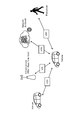
- FIG. 2 is a diagram showing an example of an overall image of V2X communication.
- the cloud server has a V2X APP server (Application Server) function.
- the cloud server is connected to the core network via a network such as the Internet.
- the core network is composed of devices having a control function for V2X communication.
- Multiple base stations are connected to the core network.
- the base station (RAN) has a function of wirelessly communicating with a terminal device (an example of UE, Vehicle in the example of FIG. 2) (for example, a Uu link connection function using a Uu interface).
- the base station has a function of supporting direct communication (for example, side link communication) such as V2V communication and V2P communication.
- An RSU Road Side Unit
- the RSU has, for example, a V2X APP providing function, a data relay function, and the like.
- V2X use case> As wireless communication for automobiles, the development of DSRC (Dedicated Short Range Communication) based on 802.11p has been mainly promoted so far. However, in recent years, the standardization of "LTE-based V2X", which is an LTE (Long Term Evolution) -based in-vehicle communication, has been carried out. In LTE-based V2X communication, the exchange of basic safety messages and the like is supported. In recent years, NR V2X communication using 5G technology (NR: New Radio) has been studied with the aim of further improving V2X communication.
- LTE-based V2X LTE (Long Term Evolution) -based in-vehicle communication
- FIG. 3 is a diagram showing an example of a use case of V2X communication.
- Use cases of V2V communication include forward approach warning, intersection collision prevention, emergency vehicle warning, platooning, overtaking cancellation warning, road construction warning, and the like.
- use cases of V2I communication include notification of road safety information, traffic light cooperation, parking lot assistance, billing, and the like.
- examples of use cases for V2P communication include warnings for vulnerable people.
- examples of V2N communication use cases include dynamic link sharing, remote driving, and in-vehicle entertainment.
- NR V2X communication supports new use cases that require high reliability, low delay, high-speed communication, and high capacity, which could not be supported by LTE-based V2X so far.
- provision of a dynamic map, remote driving, and the like can be mentioned.
- sensor data sharing in which sensor data is exchanged between vehicles and road vehicles, and platening use cases for platooning.
- Use cases and requirements for these NR V2X communications are described in 3GPP TR22.886 and the like. In the following (1) to (4), some use cases will be briefly explained.
- platooning As a use case of NR V2X communication, platooning can be mentioned.
- the platooning means that a plurality of vehicles form a platoon and travel in the same direction. Information for controlling platooning is exchanged between the vehicle leading the platooning and other vehicles.
- NR V2X communication is used to exchange this information. By exchanging information using NR V2X communication, it is possible to further reduce the inter-vehicle distance of platooning.
- the sensor information includes, for example, peripheral vehicles, sensing results by local sensors mounted on RSUs, live video images, and the like.
- the vehicle acquires sensor information via surrounding vehicles, RSUs, pedestrians, V2X application servers, and the like.
- the vehicle can obtain information that cannot be obtained from its own sensor information, and can recognize / recognize a wider range of environments. In this use case, a lot of information needs to be exchanged, so high data rate is required for communication.
- NR V2X communication examples include semi-autonomous driving and fully automatic driving.
- the RSU shares the recognition / recognition information obtained from the sensors and the like owned by the RSU to the surrounding vehicles.
- each vehicle can adjust the trajectory and operation of the vehicle in synchronization and coordination.
- each vehicle can also share the intention and intention of driving with neighboring vehicles.
- Remote Driving Use cases for NR V2X communication include remote control by remote control and V2X applications.
- Remote control is used, for example, for people who cannot drive or in dangerous areas.
- it can be applied to public transportation where the route and the road to be traveled are fixed to some extent.
- cloud computing-based maneuvers can also be used as remote control for public transport.
- communication requires high reliability and low transmission delay.
- V2X communication of this embodiment may be a use case other than these.
- Target links include Uu links, which are links between terminals and infrastructure such as base stations and RSUs, and PC5 links (side links), which are links between terminals.
- Uu links which are links between terminals and infrastructure such as base stations and RSUs
- PC5 links side links
- the following (1) to (9) are examples of main enhancements.
- Examples of channel format enhancement in (1) include Flexible numerology, Short TTI (Transmission Time Interval), multi-antenna support, and Waveform. Further, as an example of the enhancement of the side link feedback communication in (2), HARQ, CSI (Channel Status Information) and the like can be mentioned.
- V2X Operation Scenario> an example of a V2X communication operation scenario will be described with reference to FIGS. 4 to 9.
- V2N communication communication between the base station and the terminal is simple only by DL / UL communication, but in V2V communication, various communication paths can be considered.
- each scenario will be described using an example of V2V communication, but the same communication operation can be applied to V2P and V2I.
- the communication destination is not a vehicle (Vehicle) but a pedestrian (Pedestrian), a base station, or an RSU.
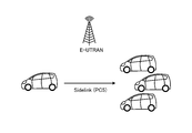
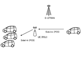
- FIG. 4 is an example of V2V communication according to scenario 1.
- a car an example of UE
- a car an example of UE
- the side link is a communication link between terminals such as PC5.
- the side link may be called a V2V communication link, a V2P communication link, a V2I communication link, or the like, in addition to the PC5.
- the car and the car communicate directly using side link communication without going through the radio access network.
- E-UTRAN Evolved Universal Terrestrial Radio Access Network
- the radio access network is not limited to E-UTRAN.
- the radio access network may be NG-RAN.
- FIG. 5 is an example of V2V communication according to scenario 2.
- the car an example of UE
- the car communicate via a radio access network.
- data is transmitted from one car to a plurality of cars.
- Uu indicates a Uu interface.
- the Uu interface is a wireless interface between a terminal and a base station.
- UL indicates uplink and DL downlink.
- E-UTRAN is shown as a wireless access network, but the wireless access network is not limited to E-UTRAN.
- the radio access network may be NG-RAN.
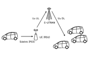
- FIG. 6 is an example of V2V communication according to scenario 3.
- the car and the car communicate with the RSU via a radio access network.
- data is transmitted from one car to a plurality of cars.
- one car and the RSU are connected by side link communication.
- E-UTRAN is shown as a wireless access network, but the wireless access network is not limited to E-UTRAN.
- the radio access network may be NG-RAN.
- the RSU is shown as a device that operates as a UE, but the RSU is not limited to this.
- the RSU may operate as a RAN or as a part (eg gNB-DU, RRH, RRU) of the RAN (E-UTRAN or NG-RAN) of FIG.
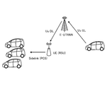
- FIG. 7 is an example of V2V communication according to scenario 4.
- the car and the car communicate with the RSU via a radio access network.
- a radio access network In the example of FIG. 7, a plurality of vehicles and an RSU are connected by side link communication.
- E-UTRAN is also shown as a wireless access network, but the wireless access network is not limited to E-UTRAN.
- the radio access network may be NG-RAN.
- the RSU is shown as a device that operates as a UE, but the RSU is not limited to this.
- the RSU may operate as a RAN or as a part (eg gNB-DU, RRH, RRU) of the RAN (E-UTRAN or NG-RAN) of FIG.
- FIG. 8 is an example of V2V communication according to scenario 5.
- the car and the car communicate via the RSU, not via the radio access network.
- the RSU shown in FIG. 8 is a fixed station type RSU.
- E-UTRAN is shown as the radio access network, but for example, the radio access network may be NG-RAN.
- the RSU is shown as a device that operates as a UE, but the RSU is not limited to this.
- the RSU may operate as a RAN or as a part (eg gNB-DU, RRH, RRU) of the RAN (E-UTRAN or NG-RAN) of FIG.
- FIG. 9 is an example of V2V communication according to scenario 6.
- the car and the car communicate via the RSU, not via the radio access network.
- the RSU shown in FIG. 9 is a mobile station type RSU.
- E-UTRAN is shown as the radio access network, but for example, the radio access network may be NG-RAN.
- the RSU is shown as a device that operates as a UE, but the RSU is not limited to this.
- the RSU may operate as a RAN or as a part (eg gNB-DU, RRH, RRU) of the RAN (E-UTRAN or NG-RAN) of FIG.
- V2X communication for example, 3GPP Rel.12 or later V2X communication
- D2D communication for example, D2D communication
- NR V2X communication for example, when V2X communication is performed in the above scenarios 1 to 6, it is necessary to perform unicast communication and group cast (multicast) communication in addition to broadcast communication, which increases the traffic volume. There is concern about deterioration of communication quality.
- NR V2X communication supports high-quality communication such as low-latency and high-reliability (URLLC) communication in side-link communication between one vehicle (an example of UE) and one vehicle. Is required to do. However, if the number of vehicles performing such side-link communication increases and the amount of traffic increases, the quality of side-link communication may deteriorate and the requirements for ultra-latency may not be satisfied.
- URLLC high-reliability
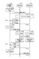
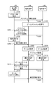
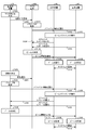
- the quality of the side link communication is improved by applying the beamforming technique to the side link communication of V2X or D2D. This point will be described with reference to FIGS. 10 and 11. 10 and 11 are diagrams for explaining the outline of the side link communication according to the first embodiment of the present disclosure.
- the information processing system includes a base station 20, and a terminal apparatus 40 1, 40 2 for the side link communication.
- the base station 20 manages the beam in the side link communication of the terminal device 40.
- the terminal device 40 executes beam measurement by measuring RSRP (RS Received Power) of a reference signal (RS: Reference Signal) while sweeping the beam, for example. (Step S1).
- the terminal device 40 notifies the base station 20 of the result of the beam measurement (step S2).
- the terminal device 40 may measure RSSI (RS Strength Indicator) or RSRQ (RS Received Quality) instead of RSRP.
- the base station 20 determines the beam to be used for the side link communication of the terminal device 40 based on the measurement result of the terminal device 40 (step S3).
- the base station 20 notifies the terminal device 40 of the determined beam information (hereinafter, also referred to as beam information) (step S4).
- the terminal device 40 generates a beam based on the beam information acquired from the base station 20, and performs side link communication using the generated beam (step S5).
- the terminal device 40 can perform side link communication by using the beamforming technique. As a result, the quality of side link communication can be improved. Further, the base station 20 determines the beam to be used for the side link communication of the terminal device 40, so that, for example, the base station 20 determines the beam of the terminal device 40 in consideration of the communication of another terminal device (not shown). Can be done. Thereby, the quality of the side link communication of the terminal device 40 can be improved.
- D2D communication with the terminal device 40 is shown as side link communication in FIGS. 10 and 11, communication using beamforming technology is also possible in V2X side link communication.
- FIG. 12 is a diagram showing a configuration example of the information processing system 1 according to the first embodiment of the present disclosure.
- the information processing system 1 shown in FIG. 12 is a mobile communication system including a plurality of communication devices (mobile device, terminal device) capable of side-link communication.
- the information processing system 1 is, for example, a wireless communication system using NR (New Radio) wireless access technology (RAT: Radio Access Technology). This wireless communication system is also called 5GS (5th Generation System).
- the information processing system 1 is not limited to the mobile phone communication system, and may be, for example, an intelligent transport system (ITS). Further, the information processing system 1 is not limited to the cellular communication system, and may be, for example, another wireless communication system such as a wireless LAN (Local Area Network) system, an aeronautical wireless system, or a space wireless communication system.
- ITS intelligent transport system
- the information processing system 1 may provide an application processing execution function (for example, an edge function) to the mobile device via a wireless network using NR wireless access technology.
- NR is a kind of cellular communication technology, and enables mobile communication of a mobile device by arranging a plurality of areas covered by the base station device in a cell shape.
- NR includes NLAT (New Radio Access Technology) and FEUTRA (Further EUTRA).
- a single base station may manage a plurality of cells.
- the cell corresponding to NR is sometimes referred to as an NR cell.
- NR is the next generation (5th generation) wireless access technology (RAT) of LTE (4th generation communication including LTE-Advanced, LTE-Advanced Pro).
- RAT wireless access technology
- LTE 4th generation communication including LTE-Advanced, LTE-Advanced Pro
- NR is a wireless access technology that can support various use cases including eMBB (Enhanced Mobile Broadband), mMTC (Massive Machine Type Communications) and URLLC (Ultra-Reliable and Low Latency Communications).
- eMBB Enhanced Mobile Broadband
- mMTC Massive Machine Type Communications
- URLLC Ultra-Reliable and Low Latency Communications
- the NR base station can be referred to as an NGRAN (Next Generation RAN) node.
- NGRAN refers to RAN (RAN with a reference point with 5GC) when the core network is 5GC (5G Core). That is, NGRAN may include gNodeB (gNB) and ng-eNodeB (ng-eNB). Further, in NR, the mobile device may be referred to as a UE (User Equipment).
- gNB gNodeB
- ng-eNB ng-eNodeB
- UE User Equipment
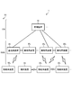
- the information processing system 1 includes a management device 10, a base station device 20, a base station device 30, a terminal device 40, and a mobile device 50. Further, FIG. 13 is a diagram showing a specific configuration example of the information processing system 1.
- the information processing system 1 may have a cloud server device CS in addition to the above configuration, but may not be an essential component.
- the network N1 is composed of these plurality of devices constituting the information processing system 1.
- the network N1 is, for example, a wireless network.
- the network N1 is a mobile communication network configured by using a wireless access technology such as NR.
- the network N1 is composed of a radio access network RAN and a core network CN.
- the device in the figure may be considered as a device (Logical node) in a logical sense. That is, a part of the devices in the figure may be realized by a virtual machine (VM: Virtual Machine), a container (Container), a docker (Docker), etc., and they may be implemented on physically the same hardware.
- VM Virtual Machine
- Container Container
- Docker docker
- the cloud server device CS (see FIG. 13) is a processing device (for example, a server device) connected to the network N2.
- the cloud server device CS is a server host computer that processes a request from a client computer (for example, a mobile device 50).
- the cloud server device CS may be a PC server, a midrange server, or a mainframe server.
- the network N2 is a communication network connected to the network N1 via a gateway device (for example, UPF, S-GW or P-GW). That is, the network N2 is Data Network (DN). Further, for example, the network N2 is a communication network such as the Internet, a regional IP (Internet Protocol) network, and a telephone network (for example, a fixed telephone network and a mobile phone network).
- the cloud server device can be rephrased as a server device, a processing device, or an information processing device.
- the management device 10 (see FIGS. 12 and 13) is a device that manages a wireless network.
- the management device 10 is a device that functions as an AMF (Access and Mobility Management Function).
- the management device 10 and the gateway device form a part of the core network CN.
- the core network CN is a network owned by a predetermined entity (subject) such as a mobile communication operator.
- the core network CN is 5GC (5G Core network).
- the predetermined entity may be the same as the entity that uses, operates, and / or manages the base station devices 20 and 30, or may be different.
- the management device 10 may have a gateway function.
- the management device 10 has a function as an UPF (User Plane Function).
- the management device 10 may be SMF, PCF, UDM, or the like.
- the core network CN may include SMF, PCF, UDM, and the like.
- the management device 10 is connected to each of the plurality of base station devices 20 and the plurality of base station devices 30.
- the management device 10 may manage the communication between the base station device 20 and the base station device 30. For example, the management device 10 manages the position of the mobile device 50 in the network N1 for each mobile device 50 in an area unit (eg Tracking Area, RAN Notification Area) composed of a plurality of cells. .. The management device 10 determines which base station device (or cell) the mobile device 50 is connected to, which base station device (or cell) is in the communication area, and the like. Each device 50 may be grasped and managed on a cell-by-cell basis.
- an area unit eg Tracking Area, RAN Notification Area
- the cell provided by the base station is called a Serving cell.
- Serving cells include PCell (Primary Cell) and SCell (Secondary Cell).
- Dual Connectivity eg EUTRA-EUTRA Dual Connectivity, EUTRA-NR Dual Connectivity (ENDC), EUTRA-NR Dual Connectivity with 5GC, NR-EUTRA Dual Connectivity (NEDC), NR-NR Dual Connectivity
- UE eg terminal device 40
- the PCell and SCell (s) provided by the MN Master Node
- the Serving cell may include a PS Cell (Primary Secondary Cell or Primary SCG Cell). That is, when Dual Connectivity is provided to the UE, PSCell and SCell (s) provided by SN (Secondary Node) are called Secondary Cell Group (SCG).
- SCG Secondary Cell Group
- One Downlink Component Carrier and one Uplink Component Carrier may be associated with one cell.
- the system bandwidth corresponding to one cell may be divided into a plurality of bandwidth parts (Bandwidth Part).
- Bandwidth Parts may be set in the UE, and one Bandwidth Part may be used in the UE as Active BWP.
- the radio resources for example, frequency band, numerology (subcarrier spacing), slot format (Slot configuration)
- Slot configuration slot format
- the base station device 20 (see FIGS. 12 and 13) is a wireless communication device that wirelessly communicates with the terminal device 40 and the mobile device 50.
- the base station device 20 is a device that constitutes a network in V2N communication.
- the base station device 20 is a type of communication device.
- the base station device 20 may be a device corresponding to a wireless base station (Base Station, Node B, eNB, gNB, etc.) or a wireless access point (Access Point). Further or instead, when the base station device is eNB, gNB, etc., it may be referred to as 3GPP Access. Further or instead, when the base station device is a wireless access point (Access Point), it may be referred to as Non-3GPP Access. Further or instead, the base station apparatus 20 may be a wireless relay station (Relay Node). Further or instead, the base station apparatus 20 may be an optical overhanging apparatus called RRH (Remote Radio Head). Further or instead, when the base station apparatus is gNB, the base station apparatus may be referred to as a combination of gNB CU (Central Unit) and gNB DU (Distributed Unit), or any of these.
- gNB CU Central Unit
- gNB DU Distributed Unit
- the gNB CU hosts multiple upper layers (e.g. RRC, SDAP, PDCP) of the Access Stratum for communication with the UE.
- gNB-DU hosts a plurality of lower layers (e.g. RLC, MAC, PHY) of Access Stratum. That is, among the messages and information described later, RRC signaling may be generated by gNB CU, while DCI may be generated by gNB-DU.
- the base station of the wireless communication system may be referred to as a base station device.
- the base station device 20 may be configured to be capable of wireless communication with another base station device 20 and the base station device 30.
- the devices may be connected by an X2 interface.
- the devices when a plurality of base station devices 20 and 30 are gNBs or a combination of eNBs and gNBs, the devices may be connected by an Xn interface. Further or instead, when a plurality of base station devices 20 and 30 are a combination of gNB CU (Central Unit) and gNB DU (Distributed Unit), the devices may be connected by an F1 interface.
- the message information (RRC signaling or DCI information) described later may be communicated between the plurality of base station devices 20 and 30 (for example, via the X2, Xn, and F1 interfaces).
- the wireless access technology used by the base station device 20 may be a cellular communication technology or a wireless LAN technology.
- the wireless access technology used by the base station apparatus 20 is not limited to these, and may be another wireless access technology.
- the wireless communication used by the base station device 20 may be wireless communication using radio waves, or wireless communication (optical wireless) using infrared rays or visible light.
- the base station device 30 (see FIGS. 12 and 13) is a wireless communication device that wirelessly communicates with the terminal device 40 and the mobile device 50. It is a device that constitutes the infrastructure in V2I communication.
- the base station device 30 is a kind of communication device like the base station device 20.
- the base station device 30 is, for example, a device corresponding to a wireless base station (Base Station, Node B, eNB, gNB, etc.) or a wireless access point (Access Point).
- a wireless base station Base Station, Node B, eNB, gNB, etc.
- Access Point Access Point
- the base station device 30 may be a wireless relay station.
- the base station device 30 may be a road base station device such as an RSU (Road Side Unit). Further, the base station device 20 may be an optical overhanging device called RRH (Remote Radio Head).
- the base station device 30 may be configured to be capable of wireless communication with another base station device 30 and the base station device 20.
- the wireless access technology used by the base station device 30 may be a cellular communication technology or a wireless LAN technology.
- the wireless access technology used by the base station apparatus 20 is not limited to these, and may be another wireless access technology.
- the wireless communication used by the base station device 30 may be wireless communication using radio waves, or wireless communication (optical wireless) using infrared rays or visible light.
- the base station devices 20 and 30 may be able to communicate with each other via the base station device-core network interface (for example, NG Interface, S1 Interface, etc.). This interface may be wired or wireless. Further, the base station devices may be able to communicate with each other via an interface between the base station devices (for example, Xn Interface, X2 Interface, etc.). This interface may be wired or wireless.
- the base station device-core network interface for example, NG Interface, S1 Interface, etc.
- This interface may be wired or wireless.
- the base station devices may be able to communicate with each other via an interface between the base station devices (for example, Xn Interface, X2 Interface, etc.). This interface may be wired or wireless.
- Base station devices 20 and 30 can be used, operated, and / or managed by various entities.
- the entities include mobile network operators (MNO: Mobile Network Operator), virtual mobile network operators (MVNO: Mobile Virtual Network Operator), virtual mobile communication enablers (MVNE: Mobile Virtual Network Enabler), and neutral.
- MNO Mobile Network Operator
- MVNO Mobile Virtual Network Operator
- MVNE Mobile Virtual Network Enabler
- the base station devices 20 and 30 may be installed and / or operated by one business operator, or may be installed and / or operated by one individual.
- the installation / operation entity of the base station device 20 is not limited to these.
- the base station devices 20 and 30 may be jointly installed and operated by a plurality of businesses or a plurality of individuals.
- the base station devices 20 and 30 may be shared equipment used by a plurality of businesses or a plurality of individuals. In this case, the installation and / or operation of the equipment may be carried out by a third party different from the user.
- the concept of a base station device includes not only a donor base station but also a relay base station (also referred to as a relay station or a relay station device). Further, the concept of a base station includes not only a structure having a function of a base station but also a device installed in the structure.
- the structure is, for example, a building such as a high-rise building, a house, a steel tower, a station facility, an airport facility, a port facility, or a stadium.
- the concept of structure includes not only buildings but also non-building structures such as tunnels, bridges, dams, walls, and iron pillars, and equipment such as cranes, gates, and windmills.
- the concept of structures includes not only structures on land (above ground in a narrow sense) or underground, but also structures on water such as piers and mega floats, and structures underwater such as ocean observation facilities.
- the base station device can be rephrased as a processing device or an information processing device.
- the base station devices 20 and 30 may be fixed stations or may be movably configured base station devices (mobile stations).
- the base station devices 20 and 30 may be devices installed on the mobile body or may be the mobile body itself.
- a relay station device having mobility can be regarded as a base station device 20 or 30 as a mobile station.
- devices that are originally mobile devices such as vehicles, drones (Aerial Vehicles), and smartphones and that are equipped with the functions of base station devices (at least some of the functions of base station devices) are also bases as mobile stations.
- station devices 20 and 30 corresponds to station devices 20 and 30.
- the mobile body may be a mobile terminal such as a smartphone or a mobile phone.
- the moving body may be a moving body (for example, a vehicle such as a car, a bicycle, a bus, a truck, a motorcycle, a train, a linear motor car, etc.) that moves on land (ground in a narrow sense), or in the ground (for example, a vehicle).
- it may be a moving body (for example, a subway) moving in a tunnel.
- the moving body may be a moving body moving on water (for example, a ship such as a passenger ship, a cargo ship, or a hovercraft), or a moving body moving underwater (for example, a submarine, a submarine, an unmanned submarine, etc.).
- the moving body may be a moving body moving in the atmosphere (for example, an aircraft such as an airplane, an airship, or a drone (Aerial Vehicle)), or a moving body moving outside the atmosphere (for example, an artificial satellite, space). It may be an artificial celestial body such as a ship, a space station, or a spacecraft).
- the base station devices 20 and 30 may be ground base station devices (ground station devices) installed on the ground.
- the base station devices 20 and 30 may be base station devices arranged on a structure on the ground, or may be base station devices installed on a mobile body moving on the ground.
- the base station devices 20 and 30 may be an antenna installed in a structure such as a building and a signal processing device connected to the antenna.
- the base station devices 20 and 30 may be a structure or a moving body itself. "Ground" is not only on land (ground in a narrow sense) but also on the ground in a broad sense including underground, water, and water.
- the base station devices 20 and 30 are not limited to the ground base station devices.
- the base station devices 20 and 30 may be non-ground base station devices (non-ground station devices) capable of floating in the air or in space.
- the base station devices 20 and 30 may be an aircraft station device or a satellite station device.
- the aircraft station device is a wireless communication device that can float in the atmosphere (including the stratosphere) such as aircraft.
- the aircraft station device may be a device mounted on an aircraft or the like, or may be an aircraft itself.
- the concept of an aircraft includes not only heavy aircraft such as airplanes and gliders, but also light aircraft such as balloons and airships.
- the concept of an aircraft includes not only heavy aircraft and light aircraft, but also rotary-wing aircraft such as helicopters and autogyros.
- the aircraft station device (or the aircraft on which the aircraft station device is mounted) may be an unmanned aerial vehicle such as a drone.
- the concept of an unmanned aerial vehicle also includes an unmanned aerial vehicle system (UAS: Unmanned Aircraft Systems) and a tethered unmanned aerial vehicle system (tethered UAS).
- UAS Unmanned Aircraft Systems
- unmanned aerial vehicle includes a light unmanned aerial vehicle system (LTA: Lighter than Air UAS) and a heavy unmanned aerial vehicle system (HTA: Heavier than Air UAS).
- LTA Lighter than Air UAS
- HTA Heavy unmanned aerial vehicle system
- HAPs High Altitude UAS Platforms
- the satellite station device is a wireless communication device that can float outside the atmosphere.
- the satellite station device may be a device mounted on a space mobile body such as an artificial satellite, or may be a space mobile body itself. Satellites that serve as satellite station equipment are low earth orbit (LEO: Low Earth Orbiting) satellites, medium earth orbit (MEO: Medium Earth Orbiting) satellites, geostationary (GEO: Geostationary Earth Orbiting) satellites, and high elliptical orbit (HEO: Highly Elliptical Orbiting). It may be any satellite.
- the satellite station device may be a device mounted on a low earth orbit satellite, a medium earth orbit satellite, a geostationary satellite, or a high elliptical orbit satellite.
- the size of the coverage of the base station devices 20 and 30 may be from a large one such as a macro cell to a small one such as a pico cell. Of course, the size of the coverage of the base station devices 20 and 30 may be extremely small, such as a femtocell. Further, the base station devices 20 and 30 may have a beamforming capability. In this case, the base station devices 20 and 30 may form a cell or a service area for each beam.
- the terminal device 40 is a wireless communication device that wirelessly communicates with the base station device 20 or the base station device 30.
- the terminal device 40 is, for example, a mobile phone, a smart device (smartphone or tablet), a PDA (Personal Digital Assistant), or a personal computer.
- the mobile device 50 may be an M2M (Machine to Machine) device or an IoT (Internet of Things) device (for example, it may be called MTC UE, NB-IoT UE, Cat.M UE).
- the terminal device 40 is capable of side link communication with the mobile device 50 and other terminal devices 40.
- the wireless communication (including side link communication) used by the terminal device 40 may be wireless communication using radio waves, or wireless communication using infrared rays or visible light (optical wireless). ..
- the mobile device 50 is a mobile wireless communication device that wirelessly communicates with the base station device 20 or the base station device 20.
- the mobile device 50 may be a wireless communication device installed on the mobile body, or may be the mobile body itself.
- the mobile device 50 may be a vehicle (Vehicle) moving on the road such as an automobile, a bus, a truck, or a motorcycle, or a wireless communication device mounted on the vehicle.
- the mobile device 50 is capable of side link communication with the terminal device 40 and other mobile devices 50.
- the mobile device 50 can use an automatic retransmission technique such as HARQ when performing side link communication.
- the wireless communication (including side link communication) used by the mobile device 50 may be wireless communication using radio waves or wireless communication using infrared rays or visible light (optical wireless). Good.
- a “mobile device” is a type of communication device, and is also referred to as a mobile station, mobile station device, terminal device, or terminal.
- the concept of "mobile device” includes not only a communication device configured to be movable but also a mobile body in which the communication device is installed.
- the moving body may be a mobile terminal, or may be a moving body that moves on land (ground in a narrow sense), in the ground, on the water, or in the water.
- the moving body may be a moving body such as a drone (Aerial UE) or a helicopter that moves in the atmosphere, or a moving body that moves outside the atmosphere such as an artificial satellite.
- the concept of a communication device includes not only a portable mobile device (terminal device) such as a mobile terminal, but also a device installed on a structure or a mobile body.
- the structure or the moving body itself may be regarded as a communication device.
- the concept of a communication device includes not only mobile devices (terminal devices, automobiles, etc.) but also base station devices (donor base stations, relay base stations, etc.).
- a communication device is a type of processing device and information processing device.
- the mobile device 50 and the terminal device 40 and the base station devices 20 and 30 are connected to each other by wireless communication (for example, radio wave or optical wireless).
- wireless communication for example, radio wave or optical wireless.
- the mobile device 50 and the terminal device 40 may be connected to a plurality of base station devices or a plurality of cells at the same time to perform communication. For example, when one base station device can provide a plurality of cells, the mobile device 50 or the terminal device 40 performs carrier aggregation by using one cell as a PCell and another cell as an SCell. Can be done.
- the mobile device 50 or the terminal device 40 has one base station device (MN (eg MeNB or MgNB)).
- MN base station device
- One or more cells to be managed are used as PCell or PCell and SCell (s), and one or more cells managed by the other base station device (SN (eg SeNB or SgNB)) are PSCell or PSCell and SCell (s).
- SN base station device
- PSCell or PSCell and SCell s
- the DC may be referred to as MC (Multi Connectivity).
- the mobile device 50 and the terminal device 40 can be combined with the mobile device 50 and the terminal device 40 by the coordinated multi-point transmission and reception (CoMP) technology via the cells of different base station devices (multiple cells having different cell identifiers or the same cell identifiers). It is also possible for the plurality of base station devices to communicate with each other.
- CoMP coordinated multi-point transmission and reception
- the mobile device 50 and the terminal device 40 do not necessarily have to be devices directly used by a person.
- the mobile device 50 and the terminal device 40 may be sensors installed in a machine or the like in a factory, such as a so-called MTC (Machine Type Communication).
- the mobile device 50 may be an M2M (Machine to Machine) device or an IoT (Internet of Things) device.
- the mobile device 50 and the terminal device 40 may be devices having a relay communication function, as represented by D2D (Device to Device) and V2X (Vehicle to everything).
- the mobile device 50 and the terminal device 40 may be devices called CPE (Client Premises Equipment) used in a wireless backhaul or the like.
- CPE Customer Premises Equipment
- the management device 10 is a device that manages a wireless network.
- the management device 10 is a device that manages the communication of the base station devices 20 and 30.
- the management device 10 may be a device having a function as, for example, AMF, SMF, UPF, or the like.
- the management device 10 has an application processing execution function (for example, an edge function) and may function as a server device such as an application server. More specifically, when the UPF is located in the local area network (that is, when the UPF is a Local UPF), a device for edge computing is provided in a DN having an N6 reference point between the UPF and the UPF. May be placed. Then, a device for edge computing may be included in the management device 10.
- the device for edge computing may operate as, for example, a MEC (Multi access Edge Computing) Platform, a MEC host, or a MEC application.
- MEC Multi access Edge Computing
- FIG. 14 is a diagram showing a configuration example of the management device 10 according to the first embodiment of the present disclosure.
- the management device 10 includes a network communication unit 11, a storage unit 12, and a control unit 13.
- the configuration shown in FIG. 17 is a functional configuration, and the hardware configuration may be different from this. Further, the functions of the management device 10 may be distributed and implemented in a plurality of physically separated configurations. For example, the management device 10 may be composed of a plurality of server devices.
- the network communication unit 11 is a communication interface for communicating with other devices.
- the network communication unit 11 may be a network interface or a device connection interface.
- the network communication unit 11 has a function of directly or indirectly connecting to the network N1.
- the network communication unit 11 may include a LAN (Local Area Network) interface such as a NIC (Network Interface Card), or may include a USB interface composed of a USB (Universal Serial Bus) host controller, a USB port, and the like. You may be. Further, the network communication unit 11 may be a wired interface or a wireless interface.
- the network communication unit 11 functions as a communication means of the management device 10. The network communication unit 11 communicates with the base station devices 20 and 30 under the control of the control unit 13.
- the storage unit 12 is a data readable / writable storage device such as a DRAM (Dynamic Random Access Memory), a SRAM (Static Random Access Memory), a flash memory, and a hard disk.
- the storage unit 12 functions as a storage means for the management device 10.
- the storage unit 12 stores, for example, the connection state of the mobile device 50.
- the storage unit 12 stores the state of the RRC (Radio Resource Control) and the state of the ECM (EPS Connection Management) of the mobile device 50.
- the storage unit 12 may function as a home memory for storing the position information of the mobile device 50.
- the control unit 13 is a controller that controls each unit of the management device 10.
- the control unit 13 is realized by, for example, a processor such as a CPU (Central Processing Unit) or an MPU (Micro Processing Unit).
- the control unit 13 is realized by the processor executing various programs stored in the storage device inside the management device 10 using a RAM (Random Access Memory) or the like as a work area.
- the control unit 13 may be realized by an integrated circuit such as an ASIC (Application Specific Integrated Circuit) or an FPGA (Field Programmable Gate Array).
- the CPU, MPU, ASIC, and FPGA can all be considered as controllers.
- the base station device 20 is a wireless communication device that performs wireless communication with the mobile device 50 (or terminal device 40), and is a communication control device that controls side link communication between the mobile device 50 (or terminal device 40). ..
- the base station device 20 is a device that functions as, for example, a radio base station, a radio relay station, a radio access point, or the like. At this time, the base station device 20 may be an optical overhanging device such as RRH.
- the base station device 20 is a device that constitutes a network in V2N communication.
- FIG. 15 is a diagram showing a configuration example of the base station device 20 according to the first embodiment of the present disclosure.
- the base station apparatus 20 includes a wireless communication unit 21, a storage unit 22, a network communication unit 23, and a control unit 24.
- the configuration shown in FIG. 15 is a functional configuration, and the hardware configuration may be different from this. Further, the functions of the base station apparatus 20 may be distributed and implemented in a plurality of physically separated configurations.
- the wireless communication unit 21 is a wireless communication interface that wirelessly communicates with another wireless communication device (for example, a mobile device 50, a terminal device 40, a base station device 30, and another base station device 20).
- the wireless communication unit 21 operates according to the control of the control unit 24.
- the wireless communication unit 21 may support a plurality of wireless access methods.
- the wireless communication unit 21 may support both NR and LTE.
- the wireless communication unit 21 may support W-CDMA or cdma2000 in addition to LTE.
- the wireless communication unit 21 may support wireless access methods other than NR, LTE, W-CDMA and cdma2000.
- the wireless communication unit 21 includes a reception processing unit 211, a transmission processing unit 212, and an antenna 213.
- the wireless communication unit 21 may include a plurality of reception processing units 211, transmission processing units 212, and antennas 213, respectively.
- each unit of the wireless communication unit 21 may be individually configured for each wireless access method.
- the reception processing unit 211 and the transmission processing unit 212 may be individually configured by LTE and NR.
- the reception processing unit 211 processes the uplink signal received via the antenna 213. For example, the reception processing unit 211 performs signal processing such as orthogonal demodulation, AD conversion, and compound processing on the uplink signal to generate uplink data and uplink control information. The reception processing unit 211 outputs the generated uplink data and uplink control information to the control unit 24.
- signal processing such as orthogonal demodulation, AD conversion, and compound processing on the uplink signal to generate uplink data and uplink control information.
- the reception processing unit 211 outputs the generated uplink data and uplink control information to the control unit 24.
- the transmission processing unit 212 performs the transmission processing of the downlink control information and the downlink data. For example, the transmission processing unit 212 performs signal processing such as coding processing, DA conversion, and quadrature modulation on the downlink control information and downlink data input from the control unit 24 to generate a downlink signal. The transmission processing unit 212 transmits the generated downlink signal from the antenna 213.
- the storage unit 22 is a data-readable / writable storage device such as a DRAM, SRAM, flash memory, and hard disk.
- the storage unit 22 functions as a storage means for the base station device 20.
- the network communication unit 23 is a communication interface for communicating with other devices (for example, a management device 10, another base station device 20, base station device 30, cloud server device CS, etc.).
- the network communication unit 23 has a function of directly or indirectly connecting to the network N1.
- the network communication unit 23 includes a LAN interface such as a NIC.
- the network communication unit 23 may be a wired interface or a wireless interface.
- the network communication unit 23 functions as a network communication means for the base station device 20.
- the network communication unit 23 communicates with other devices (for example, management device 10, cloud server device CS, etc.) under the control of the control unit 24.
- the configuration of the network communication unit 23 may be the same as that of the network communication unit 11 of the management device 10.
- the control unit 24 is a controller that controls each unit of the base station device 20.
- the control unit 24 is realized by, for example, a processor (hardware processor) such as a CPU (Central Processing Unit) or an MPU (Micro Processing Unit).
- the control unit 24 is realized by the processor executing various programs stored in the storage device inside the base station device 20 using a RAM (Random Access Memory) or the like as a work area.
- the control unit 24 may be realized by an integrated circuit such as an ASIC (Application Specific Integrated Circuit) or an FPGA (Field Programmable Gate Array).
- the CPU, MPU, ASIC, and FPGA can all be considered as controllers.
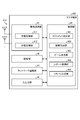
- control unit 24 controls each unit of the base station device 20, but here, the control unit 24 mainly controls the beam of the side link communication between the terminal devices 40 (or the mobile device 50). The case will be described.
- the control unit 24 of the base station device 20 determines the beam used for the side link communication between the terminal devices 40 based on the beam measurement result of the terminal device 40. Further, the control unit 24 acquires a beam report in the side link communication between the terminal devices 40 and executes beam recovery according to the report result.
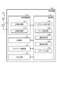
- the control unit 24 includes a measurement setting unit 241, a result acquisition unit 242, a beam determination unit 243, a report acquisition unit 244, and a recovery determination unit 245. , Equipped with.
- Each block (measure setting unit 241 to recovery determination unit 245) constituting the control unit 24 is a functional block indicating the function of the control unit 24, respectively.
- These functional blocks may be software blocks or hardware blocks.
- each of the above-mentioned functional blocks may be one software module realized by software (including a microprogram), or may be one circuit block on a semiconductor chip (die).
- each functional block may be one processor or one integrated circuit.
- the method of configuring the functional block is arbitrary.
- the control unit 24 may be configured in a functional unit different from the above-mentioned functional block.
- the measurement setting unit 241 sets the parameters required for the beam measurement executed by the terminal device 40. For example, the measurement setting unit 241 sets a resource and a cycle for the terminal device 40 to send the reference signal RS to be the target of the beam measurement.
- the following (1) to (7) are examples of the main reference signal RS targeted for beam measurement.
- SLSS Systemlink Synchronization Signal
- DMRS Demodulation reference signal
- PTRS Phase tracking reference signal
- CSI-RS Channel status indication reference signal
- SRS Sounding reference signal
- AGC Automatic gain control
- the measurement setting unit 241 notifies the terminal device 40 that executes the beam measurement of information about the beam measurement (for example, information about the reference signal RS such as a resource and a cycle for transmitting the reference signal RS).
- the measurement setting unit 241 notifies information about the beam measurement (hereinafter, also referred to as measurement information) by using the following (1) to (5), for example.
- RRC Radio Resource Control
- SIB System Information Block
- PBCH Physical Broadcast Channel
- PDCCH Physical Downlink Control Channel
- PDSCH Physical Downlink Shared Channel
- the measurement setting unit 241 determines parameters required for beam measurement, such as the beam output direction (including the beam sweeping range and period) and the beam gain when the terminal device 40 executes beam measurement. You may do so.
- the measurement setting unit 241 notifies the terminal device 40 of the determined parameter as measurement information.
- the result acquisition unit 242 acquires the result of the beam measurement from the terminal device 40.
- the beam measurement executed by the terminal device 40 will be described later with reference to FIG.
- the result acquisition unit 242 acquires RSRP (RS Received Power) of the reference signal RS measured by the terminal device 40.
- RSRP RS Received Power
- RSSI RS Strength Indicator
- RSRQ RS Received Quality
- the result acquisition unit 242 includes, for example, a synchronization signal, CBR (Channel Busy Ratio), CR (Channel occupation Ratio), position information of the terminal device 40, and an interference level (for example, SINR (signal)). -to-interference noise ratio)) and mobility information may be acquired.
- the mobility information includes information on motion parameters of the mobile body such as the speed and the traveling direction of the mobile body when the mobile device 50 such as a car performs side link communication, for example.
- the beam determination unit 243 determines the beam to be used by the terminal device 40 during side link communication based on the result of the beam measurement acquired by the result acquisition unit 242.
- the beam determining unit 243 determines the beam of both the transmitting and receiving terminal devices 40 according to, for example, the receiving power, the interference level (for example, SINR) of the transmitting side or the receiving side of the terminal device 40, or the degree of beam congestion.
- the degree of congestion of the beam is, for example, the number of terminal devices 40 that use the same beam.
- the beam determination unit 243 determines the output direction of the beam specified by at least one of the elevation angle, the azimuth angle, and the beam width of the beam, for example, as the beam used by the terminal device 40 in the side link communication. Alternatively, the beam determination unit 243 may determine the gain of the beam. The beam determination unit 243 generates beam information including the output direction of the determined beam or the gain of the beam. The beam determination unit 243 notifies the terminal device 40 that performs side link communication via the wireless communication unit 21 of the generated beam information.
- the beam determination unit 243 may generate beam information for one terminal device 40 so that the beam is different depending on whether the signal is transmitted or received. That is, the beam determination unit 243 may generate beam information for transmission and beam information for reception, respectively, and notify one terminal device 40.
- the beam determination unit 243 determines the beams of all the terminal devices 40 that perform side link communication.
- the beam determination unit 243 determines the beam for each of the plurality of side link communications. That is, the beam determination unit 243 determines the beam for each set of terminal devices 40 that perform side link communication. In this way, the beam determination unit 243 determines the beam for each of the plurality of side link communications, so that the optimum beam for each side link communication can be determined. Therefore, even when a plurality of side link communications are performed, the communication quality of each side link communication can be improved.
- the report acquisition unit 244 acquires the result of the side link communication (hereinafter, also referred to as a beam report) from the terminal device 40 that has performed side link communication using the beam determined by the beam determination unit 243.
- the beam report acquired by the report acquisition unit 244 includes at least one of a parameter related to received power, a parameter related to channel status, and a parameter related to communication performance.
- Parameters related to received power include, for example, RSRP, RSSI, RSRQ, and the like.
- parameters related to channel status include CQI (Channel Quality Indicator), PMI (Precoding Matrix Indicator), RI (Rank Indicator), and the like.
- parameters related to communication performance include, for example, CBR, CR, and HARQ (Hybrid ARQ) feedback.
- Other parameters related to communication performance include location information of the terminal device 40, traffic patterns, capabilities, and types of services provided by the terminal device 40.
- the parameters related to communication performance may include information related to power consumption such as QoS wiring for side-link communication, QoE wiring for side-link communication, transmission power, and the remaining battery level of the terminal device 40. ..
- the recovery determination unit 245 determines whether or not the beam used for the side link communication between the terminal devices 40 is a beam failure based on the beam report acquired by the report acquisition unit 244.
- the recovery determination unit 245 determines that the terminal device 40 is a beam failer when it determines that the performance of the communication channel has deteriorated when the terminal device 40 performs side link communication using the beam.
- the recovery determination unit 245 determines the communication channel when the received power of the terminal device 40 in the side link communication is smaller than the predetermined threshold value, or when the interference in the side link communication is larger than the predetermined threshold value. It is judged that the performance of the device has deteriorated.
- the recovery decision unit 245 determined to be a beam failer executes beam recovery. Specifically, the recovery determination unit 245 executes beam recovery by selecting a beam having better performance for side link communication between the terminal devices 40. The recovery determination unit 245 notifies the terminal device 40 that performs side link communication via the wireless communication unit 21 of the beam information regarding the selected beam.
- the recovery decision unit 245 executes beam recovery and selects a beam with better performance, but the present invention is not limited to this. For example, if the recovery determination unit 245 determines that the beam recovery is to be executed because the performance of the communication channel has deteriorated, the beam determination unit 243 may execute the beam recovery and select a beam having better performance. .. In this case, the beam determination unit 243 selects a beam having better performance based on the beam reporting acquired by the report acquisition unit 244.
- the base station apparatus 30 constituting the infrastructure also has a beam management function in the side link communication of the terminal apparatus 40 as well as the base station apparatus 20. May have. In this case, since the base station device 30 has the same functional configuration as the base station device 20, the description thereof will be omitted here.
- the terminal device 40 is a mobile wireless communication device.
- the terminal device 40 may be a user terminal (UE: User Equipment) such as a mobile phone or a smart device.
- UE User Equipment
- the terminal device 40 can wirelessly communicate with the base station device 20 and the base station device 30. Further, the terminal device 40 can perform side link communication with the mobile device 50 and other terminal devices 40.
- FIG. 16 is a diagram showing a configuration example of the terminal device 40 according to the first embodiment of the present disclosure.
- the terminal device 40 includes a wireless communication unit 41, a storage unit 42, a network communication unit 43, an input / output unit 44, and a control unit 45.
- the configuration shown in FIG. 16 is a functional configuration, and the hardware configuration may be different from this. Further, the functions of the terminal device 40 may be distributed and implemented in a plurality of physically separated configurations. Further, in the configuration of the terminal device 40, the network communication unit 43 and the input / output unit 44 do not have to be essential components.
- the wireless communication unit 41 is a wireless communication interface that wirelessly communicates with other wireless communication devices (for example, base station devices 20, 30, other terminal devices 40, and mobile device 50).
- the wireless communication unit 41 operates according to the control of the control unit 45.
- the wireless communication unit 41 corresponds to one or a plurality of wireless access methods.
- the wireless communication unit 41 corresponds to both NR and LTE.
- the wireless communication unit 41 may support W-CDMA and cdma2000 in addition to NR and LTE. Further, the wireless communication unit 21 may support communication using NOMA.
- the wireless communication unit 41 includes a reception processing unit 411, a transmission processing unit 412, and an antenna 413.
- the wireless communication unit 41 may include a plurality of reception processing units 411, transmission processing units 412, and antennas 413, respectively.
- each unit of the wireless communication unit 41 may be individually configured for each wireless access method.
- the reception processing unit 411 and the transmission processing unit 412 may be individually configured by LTE and NR.
- the reception processing unit 411 processes the downlink signal received via the antenna 413. For example, the reception processing unit 411 performs signal processing such as orthogonal demodulation, AD conversion, and compound processing on the downlink signal to generate downlink data and downlink control information. The reception processing unit 411 outputs the generated downlink data and downlink control information to the control unit 45.
- signal processing such as orthogonal demodulation, AD conversion, and compound processing on the downlink signal to generate downlink data and downlink control information.
- the reception processing unit 411 outputs the generated downlink data and downlink control information to the control unit 45.
- the transmission processing unit 412 performs the transmission processing of the uplink control information and the uplink data. For example, the transmission processing unit 412 performs signal processing such as coding processing, DA conversion, and quadrature modulation on the uplink control information and uplink data input from the control unit 45 to generate an uplink signal. The transmission processing unit 412 transmits the generated uplink signal from the antenna 213.
- the storage unit 42 is a data-readable / writable storage device such as a DRAM, SRAM, flash memory, and hard disk.
- the storage unit 42 functions as a storage means for the terminal device 40.
- the network communication unit 43 is a communication interface for communicating with other devices.
- the network communication unit 43 is a LAN interface such as a NIC.
- the network communication unit 43 has a function of directly or indirectly connecting to the network N1.
- the network communication unit 43 may be a wired interface or a wireless interface.
- the network communication unit 43 functions as a network communication means of the terminal device 40.
- the network communication unit 43 communicates with other devices according to the control of the control unit 45.
- the input / output unit 44 is a user interface for exchanging information with the user.
- the input / output unit 44 is an operation device for the user to perform various operations such as a keyboard, a mouse, operation keys, and a touch panel.
- the input / output unit 44 is a display device such as a liquid crystal display (Liquid Crystal Display) or an organic EL display (Organic Electroluminescence Display).
- the input / output unit 44 may be an audio device such as a speaker or a buzzer.
- the input / output unit 44 may be a lighting device such as an LED (Light Emitting Diode) lamp.
- the input / output unit 44 functions as an input / output means (input means, output means, operation means, or notification means) of the terminal device 40.
- the control unit 45 is a controller that controls each unit of the terminal device 40.
- the control unit 45 is realized by, for example, a processor (hardware processor) such as a CPU (Central Processing Unit) or an MPU (Micro Processing Unit).
- the control unit 45 is realized by the processor executing various programs stored in the storage device inside the terminal device 40 using a RAM (Random Access Memory) or the like as a work area.
- the control unit 45 may be realized by an integrated circuit such as an ASIC (Application Specific Integrated Circuit) or an FPGA (Field Programmable Gate Array).
- the CPU, MPU, ASIC, and FPGA can all be considered as controllers.
- control unit 45 controls each unit of the terminal device 40, but here, a case where the control unit 45 performs side link communication using a beam will be mainly described.
- the control unit 45 of the terminal device 40 When starting the side link communication using the beam, the control unit 45 of the terminal device 40 first executes the beam measurement based on the measurement information from the base station device 20, and notifies the base station device 20 of the execution result. After that, the control unit 45 sets a beam based on the beam information from the base station device 20, and executes side link communication using the set beam. The control unit 45 reports the result of the side link communication to the base station device 20.
- the control unit 45 includes a measurement execution unit 451, a beam setting unit 452, a communication control unit 453, a communication measurement unit 454, and a report generation unit 455. , Equipped with.
- Each block (measure execution unit 451 to report generation unit 455) constituting the control unit 45 is a functional block indicating the function of the control unit 45, respectively.
- These functional blocks may be software blocks or hardware blocks.
- each of the above-mentioned functional blocks may be one software module realized by software (including a microprogram), or may be one circuit block on a semiconductor chip (die).
- each functional block may be one processor or one integrated circuit.
- the method of configuring the functional block is arbitrary.
- the control unit 45 may be configured in a functional unit different from the above-mentioned functional block.
- the measurement execution unit 451 executes the beam measurement based on the measurement information received from the base station device 20.
- the measurement execution unit 451 transmits a reference signal RS transmitted by another terminal device 40, which is a communication partner of side link communication, while sweeping a beam having a predetermined output direction and gain according to, for example, an instruction from the base station device 20.
- the measurement execution unit 451 calculates, for example, the RSRP of the received reference signal RS.
- the measurement execution unit 451 may calculate the RSSI and RSRQ of the reference signal RS.
- the measurement execution unit 451 includes, for example, a synchronization signal, CBR (Channel Busy Ratio), CR (Channel occupation Ratio), position information of its own device, and interference level (for example, SINR (signal-to)). -interference noise ratio)) and collect mobility information.
- CBR Channel Busy Ratio
- CR Channel occupation Ratio
- interference level for example, SINR (signal-to)). -interference noise ratio)
- the measurement execution unit 451 notifies the base station apparatus 20 of the calculated or collected information as a measurement report via the wireless communication unit 41.
- the measurement execution unit 451 executes the beam measurement as the receiving side of the reference signal RS has been described, but for example, the measurement execution unit 451 may execute the beam measurement as the transmitting side.
- the measurement execution unit 451 transmits the reference signal RS to another terminal device 40, which is the communication partner of the side link communication, at a predetermined cycle, for example, according to the instruction from the base station device 20. At this time, the measurement execution unit 451 may transmit the reference signal RS while sweeping the beam having a predetermined output direction and gain according to the instruction from the base station apparatus 20.
- the other terminal device 40 which is the communication partner of the side link communication, notifies the base station device 20 of the measurement report as the receiving side of the reference signal RS.
- the beam setting unit 452 sets the beam to be used for the side link communication based on the beam information notified from the base station device 20.
- the beam setting unit 452 sets the output direction of the beam specified by at least one of the elevation angle, the azimuth angle, and the beam width of the beam, for example, as a beam used in the side link communication.
- the beam setting unit 452 may set the gain of the beam. Further, the beam setting unit 452 may set different beams depending on whether the signal is transmitted or received.
- the communication control unit 453 controls the wireless communication unit 41 so as to perform side link communication with another terminal device 40 which is a communication partner by using the beam set by the beam setting unit 452.
- the terminal device 40 can perform side-link communication with another terminal device 40 using a beam, and the quality of the side-link communication can be improved.
- the communication measurement unit 454 measures the communication status of the side link communication by the communication control unit 453.
- the communication measurement unit 454 measures at least one of a parameter related to received power, a parameter related to channel status, and a parameter related to communication performance, for example, at a predetermined cycle.
- Parameters related to received power include, for example, RSRP, RSSI, RSRQ, and the like.
- parameters related to channel status include CQI (Channel Quality Indicator), PMI (Precoding Matrix Indicator), RI (Rank Indicator), and the like.
- parameters related to communication performance include, for example, CBR, CR, and HARQ (Hybrid ARQ) feedback.
- Other parameters related to communication performance include location information of the terminal device 40, traffic patterns, capabilities, and types of services provided by the terminal device 40.
- the parameters related to communication performance may include information related to power consumption such as QoS wiring for side-link communication, QoE wiring for side-link communication, transmission power, and the remaining battery level of the terminal device 40. ..
- the report generation unit 455 generates the result of the side link communication as a beam report based on each parameter measured by the communication measurement unit 454, and notifies the base station device 20 of the result.
- the report generation unit 455 notifies the base station apparatus 20 of the beam report by using, for example, the uplink PUCCH or PUSCH.
- the resource for notifying the beam report shall be set by the notification from the base station apparatus 20. Alternatively, the resource may be preset.
- the beam setting unit 452 resets the beam based on the beam recovery by the base station apparatus 20.
- the communication control unit 453 performs side link communication using the beam reset by the beam setting unit 452.
- FIG. 17 is a sequence diagram for explaining the flow of the side link communication process according to the first embodiment of the present disclosure.
- the base station apparatus 20 sets the necessary parameters to the beam a measurement in the terminal apparatus 40 1, 40 2 (step S101).
- the base station apparatus 20 notifies the measurement information including the parameters set in the terminal apparatus 40 1, 40 2 (step S102).
- the terminal apparatus 40 1, 40 2 performs the beam a measurement (step S103).
- the terminal devices 40 1 and 40 2 notify the base station device 20 of the result of the executed beam measurement as a measurement report (steps S104 and S105).
- the base station apparatus 20 determines the beam to be used for the side link communication terminal apparatus 40 1, 40 2 (step S106).
- the base station apparatus 20 notifies the beam information about the determined beam to the terminal apparatus 40 1, 40 2 (step S107).
- Terminal device 40 1, 40 2 which has received the beam information, set the beam (step S108, S109), executes the side link communication at the set beam (S110).
- the terminal devices 40 1 and 40 2 measure the communication status of the side link communication being executed (steps S111 and S112), and notify the base station device 20 of the measurement result as a beam report (steps S113 and S114).
- the base station apparatus 20 determines whether or not it is a beam failer, and executes beam recovery if necessary (step S115).
- the base station device 20 notifies the result of the beam recovery terminal apparatus 40 1, 40 2 as beam information (step SS 116).
- the terminal device 40 1, 40 2 carried between the sensing of a communication environment in step S 111, S112 at predetermined intervals using a beam based on an instruction from the base station apparatus 20 has made a side link communication And notify the beam report. Further, in FIG. 17, the case where the base station apparatus 20 executes beam recovery has been described as an example, but when it is determined that the base station apparatus 20 is not a beam failer, step S115 by the base station apparatus 20 is omitted. To do.
- FIG. 18 is a diagram showing a configuration example of the base station device 20 according to the first modification of the first embodiment of the present disclosure.
- the base station apparatus 20 shown in FIG. 18 includes a constraint determination unit 246 instead of the beam determination unit 243.
- Other components are the same as in FIG.
- the constraint determination unit 246 determines the constraint condition of the beam used by the terminal device 40 during the side link communication based on the result of the beam measurement acquired by the result acquisition unit 242.
- the constraint determination unit 246 determines, for example, possible ranges of the elevation angle, the azimuth angle, and the beam width of the beam as constraint conditions in the output direction of the beam.
- the constraint determination unit 246 may determine the range of the beam gain as a constraint condition.
- the constraint determination unit 246 notifies the terminal device 40 of the determined constraint condition as constraint information.
- the recovery determination unit 245 executes beam recovery by changing the constraint conditions.
- the recovery determination unit 245 notifies the terminal device 40 of the changed constraint condition.
- the terminal device 40 has the same functional configuration as the terminal device 40 shown in FIG. 16 except that the beam setting unit 452 determines the beam based on the constraint information from the base station device 20.
- the method of determining the beam by the terminal device 40 is the same as the determination method in the beam determination unit 243 of the base station apparatus 20 shown in FIG. 15, except that the beam is determined within the range of the constraint information, and thus the description thereof is omitted. To do.
- FIG. 19 is a sequence diagram for explaining the flow of the side link communication process according to the first modification of the first embodiment of the present disclosure.
- the same processing as the side link communication processing shown in FIG. 17 is designated by the same reference numerals and the description thereof will be omitted.
- the base station apparatus 20 receives the measurement report from the terminal apparatus 40 1, 40 2, based on the measurement report, to determine the beam constraints (step S201).
- the base station apparatus 20 notifies the restriction information regarding the determined constraints to the terminal device 40 1, 40 2 (step S202).
- the beam determines (step S203, S204), performs side link communication using the determined beam (step S110).
- the base station apparatus 20 when executing the beam recovery step S115, notifies the terminal apparatus 40 1, 40 2 results beam recovery as a constraint information (step SS205).
- the beam setting unit 452 determines the beam based on the constraint information, so that the beam setting unit 452 can reduce the load of the beam determination process as compared with the case where the beam is determined without the constraint condition. it can. Further, since the base station apparatus 20 may also determine the constraint conditions instead of the beam itself, the beam determination processing load can be reduced.
- a terminal device are within coverage (here, for example, the terminal device 40 1), (in this case, for example, the terminal apparatus 40 2) terminals are out of coverage to a base station apparatus
- the beam information and the like notified by 20 are relayed.
- the terminal device 40 2 are in the out-of-coverage of the base station apparatus 20 will be able to obtain the information necessary to configure the beam, side links the terminal device 40 1, 40 2 is using beam You will be able to communicate.
- the terminal apparatus 40 2 notifies a measurement report, etc. to notify the base station apparatus 20 addressed similarly to the relay terminal device 40 1 to the base station apparatus 20.
- the device which relays between the terminal devices 40 2 and the base station device 20 and the terminal device 40 1 is not limited to this, for example, the terminal device 40 other than 1 terminal device 40 and the mobile device 50, a base station device other than the base station device 20 may relay.
- FIG. 20 is a diagram for explaining an outline of side link communication according to the second embodiment of the present disclosure.
- the base station apparatus 20 does not determine the beam, but the terminal apparatus in which the authority for determining the beam is set from the base station apparatus 20 (hereinafter, also referred to as a master terminal). ) 400 determines the beam.
- the information processing system includes a base station device 20, the master terminal 400, the terminal apparatus 40 1, 40 2 for the side link communication.
- the master terminal 400 manages the beam in the side link communication of the terminal device 40.
- the base station device 20 designates the terminal device 400 as a master terminal that performs beam management of side link communication between the terminal devices 40 1 and 40 2 (step S10). Since the method of beam management by the master terminal 400 is the same as the beam management by the base station 20 shown in FIGS. 10 and 11, the description thereof will be omitted.
- FIG. 21 is a diagram showing a configuration example of the base station apparatus 20 according to the second embodiment of the present disclosure.
- the control unit 24 includes an information acquisition unit 247, a terminal determination unit 248, and a release determination unit 249 in place of the measurement setting unit 241 to the recovery determination unit 245.
- the information acquisition unit 247 acquires information necessary for determining the master terminal 400 from the terminal device 40.
- the information acquisition unit 247 acquires information on, for example, capability from the terminal device 40.
- the information acquisition unit 247 may acquire the position information of the terminal device 40.
- the terminal determination unit 248 determines the master terminal 400 based on the information acquired by the information acquisition unit 247. For example, the terminal determining unit 248, based on the position information of the terminal device 40 the information acquisition section 247 has acquired, to determine the terminal device 40 in the vicinity of the terminal device 40 1, 40 2 for the side link communication to the master terminal 400 .. The terminal determination unit 248 transmits an authority grant notification for granting authority to the determined master terminal 400 via the wireless communication unit 21.
- the terminal determination unit 248 grants authority by instructing the determined procedure or parameter of the master terminal 400, for example.
- the terminal determination unit 248 gives such an instruction using, for example, RRC, SIB, DCI (Downlink Control Information), PDCCH, PDSCH, or the like.
- the cancellation decision unit 249 decides to cancel the authority given to the master terminal 400.
- the release decision unit 249 decides to release the authority based on, for example, the capability and position information of the master terminal 400.
- the release determination unit 249 may determine the release of the authority according to the release request from the master terminal 400 and the communication status of the terminal device 40.
- release determining unit 249 the beam management by the master terminal 400, when the quality of the communication terminal apparatus 40 1, 40 2 other than the terminal device 40 is performing is determined to be degraded, releasing the permission of the master terminal 400 .
- release determining unit 249 when at least one of the terminal apparatus 40 1, 40 2 is determined to have become out-of-coverage of the master terminal 400 may release the authority of the master terminal 400.
- Release determination unit 249 shall be performed based e.g. the determination of the position information of the terminal apparatus 40 1, 40 2 and the master terminal 400.
- release determining unit 249 based on the notification from the master terminal 400 or the terminal device 40 1, 40 2, it may be performed the determination.
- the cancellation decision unit 249 transmits a cancellation notification to the master terminal 400 that has decided to cancel via the wireless communication unit 21.
- the terminal determination unit 248 transmits a cancellation notification using, for example, RRC, SIB, DCI (Downlink Control Information), PDCCH, PDSCH, or the like.
- the cancellation decision unit 249 omits the cancellation decision and the transmission of the cancellation notification by including the expiration date in the authority grant notification. You may try to do so.
- the master terminal 400 is a mobile wireless communication device.
- the master terminal 400 may be a user terminal (UE: User Equipment) such as a mobile phone or a smart device.
- UE User Equipment
- the master terminal 400 may be a UE-type RSU.
- the master terminal 400 can wirelessly communicate with the base station device 20 and the base station device 30. Further, the master terminal 400 can perform side link communication with the mobile device 50 and other terminal devices 40.
- the master terminal 400 includes a wireless communication unit 41, a storage unit 42, a network communication unit 43, an input / output unit 44, and a control unit 46.
- the configuration shown in FIG. 22 is a functional configuration, and the hardware configuration may be different from this. Further, the functions of the master terminal 400 may be distributed and implemented in a plurality of physically separated configurations. Further, in the configuration of the master terminal 400, the network communication unit 43 and the input / output unit 44 do not have to be essential components.
- the functional configurations of the wireless communication unit 41, the storage unit 42, the network communication unit 43, and the input / output unit 44 are the wireless communication unit 41, the storage unit 42, the network communication unit 43, and the input / output unit of the terminal device 40 shown in FIG. Since it is the same as 44, the description thereof will be omitted.
- the control unit 46 is a controller that controls each unit of the master terminal 400.
- the control unit 46 is realized by, for example, a processor (hardware processor) such as a CPU (Central Processing Unit) or an MPU (Micro Processing Unit).
- the control unit 46 is realized by the processor executing various programs stored in the storage device inside the master terminal 400 using a RAM (Random Access Memory) or the like as a work area.
- the control unit 46 may be realized by an integrated circuit such as an ASIC (Application Specific Integrated Circuit) or an FPGA (Field Programmable Gate Array).
- the CPU, MPU, ASIC, and FPGA can all be considered as controllers.
- control unit 46 controls each unit of the master terminal 400, but here, mainly, the control unit 46 receives the authority from the base station device 20 and receives the authority from the base station device 20 to control the terminal device 40 (or the mobile device). A case where beam control of side link communication between 50) is performed will be described.
- the control unit 46 of the master terminal 400 determines the beam used for the side link communication between the terminal devices 40 based on the beam measurement result by the terminal device 40. Further, the control unit 46 acquires a beam report in the side link communication between the terminal devices 40 and executes beam recovery according to the report result.
- the control unit 46 includes a measurement setting unit 461, a result acquisition unit 462, a beam determination unit 463, a report acquisition unit 464, and a recovery determination unit 465. , Equipped with.
- Each block (measure setting unit 461 to recovery determination unit 465) constituting the control unit 46 is a functional block indicating the function of the control unit 46, respectively.
- These functional blocks may be software blocks or hardware blocks.
- each of the above-mentioned functional blocks may be one software module realized by software (including a microprogram), or may be one circuit block on a semiconductor chip (die).
- each functional block may be one processor or one integrated circuit.
- the method of configuring the functional block is arbitrary.
- the control unit 46 may be configured in a functional unit different from the above-mentioned functional block.
- each block (measurement setting unit 461 to recovery determination unit 465) constituting the control unit 46 is as follows for each block (measurement setting unit) constituting the control unit 24 of the base station apparatus 20 shown in FIG. Since it is the same as 241 to recovery determination unit 245), the description thereof will be omitted.
- FIG. 23 is a sequence diagram for explaining the flow of the side link communication process according to the second embodiment of the present disclosure.
- the base station apparatus 20 determines the master terminal 400 (step S301).
- the base station apparatus 20 transmits an authorization notification to the determined master terminal (step S302).
- steps S101 to S110 is the same as the processing of FIG. 17, except that the base station apparatus 20 replaces the master terminal 400, and thus the description thereof will be omitted.
- step S303 when the base station apparatus 20 decides to release the authority of the master terminal 400 (step S303), the base station apparatus 20 transmits a release notification to the master terminal 400 (step S304).
- step S304 when releasing the permission of the master terminal 400, the base station apparatus 20, instead of the master terminal 400 executes the beam management of side links communication terminals 40 1, 40 2. Since the following processing is the same as the processing of FIG. 17, the description thereof will be omitted.
- the master terminal 400 has been to determine the beam of the side links communication terminals 40 1, 40 2, for example, the master terminal 400, so as to determine the beam constraints May be good.
- the master terminal 400 includes a constraint determination unit 246 instead of the beam determination unit 243, and the beam acquired by the result acquisition unit 242, similarly to the base station device 20 according to the first modification of the first embodiment. Based on the measurement result, the constraint condition of the beam used by the terminal device 40 during the side link communication is determined. Similarly, the terminal device 40 that performs side link communication determines the beam based on the constraint information notified by the master terminal 400.
- the master terminal 400 can perform beam management by determining the constraint conditions of the beam.
- the base station apparatus 20 is performing the beam management of side links communication terminals 40 1, 40 2, but is not limited thereto.
- the other terminal device 40 may be determined as a new master terminal and the authority may be granted.
- the beam determination units 243 and 463 determine the beam based on the measurement report, but the beam is not limited thereto.
- the base station apparatus 20 or the master terminal 400 may determine the beam based on machine learning.
- the base station device 20 or the master terminal 400 receives the measurement report result (for example, the position information of the terminal device 40, the RSRP of the reference signal RS, etc.) as an input, and learns in advance a model that outputs the beam information. deep. Learning of such a model is performed by, for example, deep learning (DNN). Alternatively, in addition to DNN, various neural networks such as RNN (Recurrent Neural Networks) and CNN (Convolutional Neural Network) can be used. Further, the learning model using DNN or the like is not limited, and a learning model learned by various other machine learning such as a decision tree or a support vector machine can also be used. It is assumed that such a model is stored in the storage units 22 and 42, for example.
- DNN deep learning
- various neural networks such as RNN (Recurrent Neural Networks) and CNN (Convolutional Neural Network) can be used.
- the learning model using DNN or the like is not limited, and a learning model learned by various other machine learning such as a decision tree
- the base station device 20 or the master terminal 400 takes the result of the measurement report acquired from the terminal device 40 as an input and determines the beam based on the machine learning model.
- the base station device 20 or the master terminal 400 may determine the beam by machine learning based on, for example, the position information of the terminal device 40, the beam that can be output, and the communication status of the other terminal device 40. In this way, by using machine learning, the base station apparatus 20 or the master terminal 400 determines the beam to be used for the side link communication of the terminal apparatus 40 by using information other than the result of beam sweeping or beam measurement. You can also. As a result, beam sweeping and beam measurement by the terminal device 40 can be omitted, and the processing load of the terminal device 40 can be reduced.
- the terminal device 40 that performs side-link communication executes measurement, but the present invention is not limited to this.
- a terminal device other than the terminal device 40 that performs side-link communication (hereinafter, also referred to as a substitute terminal) may execute the measurement instead of the terminal device 40.
- the base station device 20 may specify a proxy terminal that executes the measurement, or the terminal device 40 that performs side-link communication may specify a proxy terminal that executes the measurement.
- the base station device 20 or the terminal device 40 that performs side-link communication transmits a request for measurement agency, so that the agency terminal acts on behalf of the measurement.
- the proxy terminal notifies the base station device 20 or the terminal device 40 that performs side link communication of the measurement result.
- the terminal device 40 receives the measurement result, the terminal device 40 notifies the base station device 20 of the received measurement result.
- the terminal device 40 1 for side link communication, 40 2 but has to perform the beam reporting to the base station device 20 destined respectively, are not limited to ..
- the terminal device 40 may use the PSCCH of the side link communication to notify the terminal device 40, which is a communication partner, of the beam report. For example, to notify the recipient terminal 40 1 of the transmission side terminal 40 2 to the beam reports, to the terminal apparatus 40 2 is the base station apparatus 20, by using the PUCCH for uplink, the terminal device 40 first beam The report and the beam report of the own device may be notified.
- the terminal device 40 2 on the transmitting side notifies the beam report to the receiving side terminal device 40 1, the terminal apparatus 40 1, and notifies the base station apparatus 20 are collectively terminal apparatus 40 1, 40 2 of the beam Reports You may.
- the terminal apparatus 40 1, 40 2 may notify the beam report to the communication each partner.
- the terminal apparatus 40 1, 40 2 may notify the beam report to the base station device 20 as a representative.
- the terminal device 40 uses PSCCH to notify the communication partner of the beam report, but for example, PSCH or PSFCH may be used for notification. Further, the terminal device 40 may use the PUSCH instead of the PUCCH to notify the base station device 20 of the beam report.
- the base station apparatus 20 or the master terminal 400 determines the beam failer and executes beam recovery, but the present invention is not limited to this.
- the terminal device 40 may determine the beam failer and perform beam recovery.
- the terminal device 40 may determine the beam failer and, if necessary, request the base station device 20 or the master terminal 400 to perform beam recovery.
- the terminal device 40 1 may be to request determination of beam Failure to terminal apparatus 40 2 which is a communication partner.
- the terminal device 40 which is requested determination of the beam Feiler 2. May request the execution of a beam recovery base station apparatus or the master terminal 400 if necessary, the terminal apparatus 40 2 may perform the beam recovery.
- the terminal device 40 2 may notify the judgment result of the beam Failure to terminal apparatus 40 1.
- the terminal device 40 1, the base station apparatus or master terminal 400 may request the execution of the beam recovery, the terminal device 40 1 may perform the beam recovery.
- the base station apparatus 20 may grant authority to a plurality of master terminals 400.
- the base station apparatus 20 may set the master terminal 400 for each side link communication.
- one master terminal 400 may be set for a plurality of side link communications.
- a plurality of master terminals 400 that perform beam management of one or more side link communications may be set. It is assumed that the plurality of master terminals 400 share information with each other using PSCCH.
- the present invention is not limited to this.
- the technology according to the present disclosure can be applied to wireless access technology other than NR.
- the information processing system 1 may adopt LTE as the wireless access technology, or may adopt both LTE and NR.
- the information processing system 1 may employ wireless access technology other than NR and LTE.
- the base station devices 20 and 30, the terminal device 40, the mobile device 50, and the master terminal 400 of the present embodiment may be realized by a dedicated computer system or a general-purpose computer system.
- a program for executing the above operation is stored and distributed in a computer-readable recording medium such as an optical disk, a semiconductor memory, a magnetic tape, a flexible disk, or a hard disk.
- the control device is configured by installing the program on a computer and executing the above-mentioned processing.
- the control device may be an external device (for example, a personal computer) of the base station devices 20, 30, the terminal device 40, the mobile device 50, or the master terminal 400.
- the control device may be a device inside a base station device 20, 30, a terminal device 40, a mobile device 50, or a master terminal 400 (for example, a control unit 13 or a control unit 140).
- the above communication program may be stored in a disk device provided in a server device on a network such as the Internet so that it can be downloaded to a computer or the like.
- the above-mentioned functions may be realized by collaboration between the OS (Operating System) and the application software.
- the part other than the OS may be stored in a medium and distributed, or the part other than the OS may be stored in the server device so that it can be downloaded to a computer or the like.
- each component of each device shown in the figure is a functional concept, and does not necessarily have to be physically configured as shown in the figure. That is, the specific form of distribution / integration of each device is not limited to the one shown in the figure, and all or part of the device is functionally or physically dispersed / physically distributed in arbitrary units according to various loads and usage conditions. Can be integrated and configured.
- the communication control device (for example, the base station device 20 and the master terminal 400) includes a control unit (for example, control units 24 and 46).
- Control unit for example, control units 24 and 46.
- a side link communication between the first communication device or the second communication device Notify at least one of the first communication device and the second communication device of beam information regarding the beam used in the side link communication.
- the first and second communication devices can perform side link communication using the beam, and can perform high quality side link communication. Further, an appropriate beam can be set without increasing the processing addition of the first and second communication devices, and the communication quality of the side link communication can be further improved.
- the present technology can also have the following configurations.
- Side link communication between a first communication device and a second communication device wherein beam information about a beam used by the first communication device or the second communication device in the side link communication is transmitted to the first communication device or the first communication device or the said.
- the control unit notifies the beam information including information about at least one of the output directions or gains of the beam.
- the communication according to at least one of (1) to (3), wherein at least one of the first communication device and the second communication device performs the side link communication using the beam generated based on the beam information.
- Control device. (5) The control unit notifies at least one of the first communication device and the second communication device of the beam information including the constraint condition of the beam. At least one of the first communication device and the second communication device determines the beam within the range of the constraint condition, and performs the side link communication using the determined beam (1) to (3).
- the communication control device according to one.
- (6) The communication control device according to (5), wherein the constraint condition includes at least one of the output direction range or the gain range of the beam.
- the communication control according to at least one of (1) to (6), wherein the control unit generates the beam information based on the beam measurement information acquired from at least one of the first communication device and the second communication device. apparatus.
- the control unit generates at least one of the beam information (1) to (6) based on the beam measurement information acquired from the first communication device and the third communication device different from the second communication device.
- the communication control device described.
- the communication control device according to (7) or (8), wherein the beam measurement information includes information regarding a measurement result of a reference signal transmitted by either the first communication device or the second communication device.
- Information information system 10 Management device 20, 30 Base station device 40 Terminal device 50 Mobile device 11, 23, 43 Network communication unit 12, 22, 42 Storage unit 13, 24, 45 Control unit 21, 41 Wireless communication unit 44 Output unit 211, 411 Reception processing unit 212, 412 Transmission processing unit 213, 413 Antenna
Abstract
A communication control device (20) according to this disclosure comprises a control unit (24). The control unit (24) notifies a first communication device (40 1 ) and/or a second communication device (40 2 ) of beam information relating to a beam used by a first communication device (40 1 ) or a second communication device (40 2 ) in sidelink communications between a first communication device (40 1 ) and a second communication device (40 2 ).
Description
本開示は、通信制御装置、通信制御方法および通信制御プログラムに関する。
The present disclosure relates to a communication control device, a communication control method, and a communication control program.
セルラー移動通信の無線アクセス方式および無線ネットワーク(以下、「Long Term Evolution(LTE)」、「LTE-Advanced(LTE-A)」、「LTE-Advanced Pro(LTE-A Pro)」、「New Radio(NR)」、「New Radio Access Technology(NRAT)」、「Evolved Universal Terrestrial Radio Access(EUTRA)」、または「Further EUTRA(FEUTRA)」とも称する)が、第三世代パートナーシッププロジェクト(3rd Generation Partnership Project: 3GPP)において検討されている。なお、以下の説明において、LTEは、LTE-A、LTE-A Pro、およびEUTRAを含み、NRは、NRAT、およびFEUTRAを含む。LTEおよびNRでは、基地局装置(基地局)はeNodeB(evolved NodeB)、端末装置(移動局、移動局装置、端末)はUE(User Equipment)とも称する。LTEおよびNRは、基地局装置がカバーするエリアをセル状に複数配置するセルラー通信システムである。単一の基地局装置は複数のセルを管理してもよい。
Wireless access method and wireless network for cellular mobile communication (hereinafter, "Long Term Evolution (LTE)", "LTE-Advanced (LTE-A)", "LTE-Advanced Pro (LTE-A Pro)", "New Radio ( NR) ”,“ New Radio Access Technology (NRAT) ”,“ Evolved Universal Terrestrial Radio Access (EUTRA) ”, or“ Further EUTRA (FEUTRA) ”) is the third generation partnership project (3rd Generation Partnership Project: 3GPP). ) Is being considered. In the following description, LTE includes LTE-A, LTE-A Pro, and EUTRA, and NR includes NRAT and FEUTRA. In LTE and NR, the base station device (base station) is also referred to as eNodeB (evolved NodeB), and the terminal device (mobile station, mobile station device, terminal) is also referred to as UE (User Equipment). LTE and NR are cellular communication systems in which a plurality of areas covered by a base station apparatus are arranged in a cell shape. A single base station device may manage multiple cells.
LTEにおいて、車車間通信(Vehicle-to-Vehicle(V2V) communication)や車人間通信(Vehicle-to-Pedestrian(V2P) communication)、車インフラ間通信(Vehicle-to-Infrastructure/network(V2I/N) communication)など、自動車における様々な通信(Vehicle-to-Anything(V2X) communication)がサポートされた。LTEにおけるV2Xでは、運転補助や自動運転、歩行者への警告、などのユースケースをサポートする。V2Xをサポートするために、サイドリンク(デバイス間通信(Device to Device(D2D) communication)とも呼称される)が用いられる。なお、V2X通信を初めとしたサイドリンク通信については、例えば特許文献1に開示されている。
In LTE, vehicle-to-Vehicle (V2V) communication, vehicle-to-Pedestrian (V2P) communication, and vehicle-to-Infrastructure / network (V2I / N) Various communications (Vehicle-to-Anything (V2X) communication) in automobiles such as communication) are supported. V2X in LTE supports use cases such as driving assistance, autonomous driving, and warnings to pedestrians. Sidelinks (also called Device-to-Device (D2D) communication) are used to support V2X. In addition, side link communication including V2X communication is disclosed in, for example, Patent Document 1.
ところで、従来のD2DやV2Xでは、ブロードキャスト通信がサポートされていた。これに対して、上述の通り多様なユースケースをサポートするために、ブロードキャスト通信に加えて、ユニキャスト通信やグループキャスト(マルチキャスト)通信のサポートが検討されている。このような背景から、NR V2Xに代表される端末装置間における装置間通信(サイドリンク通信)において、高品質のユニキャスト通信やグループキャスト通信を実現するために、当該装置間通信に対して、MIMO(Multiple Input Multiple Output)やビームフォーミング技術の適用が求められている。
By the way, in the conventional D2D and V2X, broadcast communication was supported. On the other hand, in order to support various use cases as described above, support for unicast communication and group cast (multicast) communication is being studied in addition to broadcast communication. Against this background, in order to realize high-quality unicast communication and groupcast communication between device-to-device communication (side link communication) between terminal devices represented by NR V2X, in order to realize high-quality inter-device communication, The application of MIMO (Multiple Input Multiple Output) and beamforming technology is required.
そこで、本開示では、端末装置間における装置間通信において、高品質なサイドリンク通信の実現を可能とする技術を提案する。
Therefore, this disclosure proposes a technology that enables the realization of high-quality side-link communication in device-to-device communication between terminal devices.
本開示によれば、通信制御装置が提供される。通信制御装置は、制御部を備える。制御部は、第1通信装置と第2通信装置との間のサイドリンク通信であって、前記第1通信装置または前記第2通信装置が当該サイドリンク通信で用いるビームに関するビーム情報を前記第1通信装置または前記第2通信装置の少なくとも一方に通知する。
According to the present disclosure, a communication control device is provided. The communication control device includes a control unit. The control unit is a side link communication between the first communication device and the second communication device, and the first communication device or the second communication device obtains beam information about a beam used in the side link communication. Notify at least one of the communication device or the second communication device.
以下に、本開示の各実施形態について図面に基づいて詳細に説明する。なお、以下の各実施形態において、同一の部位には同一の符号を付することにより重複する説明を省略する。
Hereinafter, each embodiment of the present disclosure will be described in detail based on the drawings. In each of the following embodiments, the same parts are designated by the same reference numerals, so that duplicate description will be omitted.
また、本明細書および図面において、実質的に同一の機能構成を有する複数の構成要素を、同一の符号の後に異なる数字を付して区別する場合もある。例えば、実質的に同一の機能構成を有する複数の構成を、必要に応じて基地局装置201、および202のように区別する。ただし、実質的に同一の機能構成を有する複数の構成要素の各々を特に区別する必要がない場合、同一符号のみを付する。例えば、基地局装置201、および202を特に区別する必要が無い場合には、単に基地局装置20と称する。
Further, in the present specification and the drawings, a plurality of components having substantially the same functional configuration may be distinguished by adding different numbers after the same reference numerals. For example, distinguishing a plurality of the configuration, the base station apparatus 20 1 as needed, and as 20 2 having substantially the same function and structure. However, if it is not necessary to distinguish each of the plurality of components having substantially the same functional configuration, only the same reference numerals are given. For example, the base station apparatus 20 1, and when there is no particular need to distinguish between the 20 2, simply referred to as a base station apparatus 20.
また、以下に示す項目順序に従って本開示を説明する。
1.はじめに
1-1.V2X通信全体像
1-2.V2Xユースケース
1-3.物理レイヤエンハンスメント
1-4.V2Xオペレーションシナリオ
2.第1の実施形態
2-1.第1の実施形態の概要
2-2.情報処理システムの構成
2-3.サイドリンク通信処理の流れ
3.第1の実施形態の変形例
3-1.変形例1
3-2.変形例2
4.第2の実施形態
4-1.第2の実施形態の概要
4-2.情報処理システムの構成
4-3.サイドリンク通信処理の流れ
5.第2の実施形態の変形例
5-1.変形例1
5-2.変形例2
6.その他の変形例
7.むすび In addition, the present disclosure will be described according to the order of items shown below.
1. 1. Introduction 1-1. Overview of V2X communication 1-2. V2X use case 1-3. Physical layer enhancement 1-4. V2X operation scenario 2. First Embodiment 2-1. Outline of the first embodiment 2-2. Information processing system configuration 2-3. Flow of side link communication processing 3. Modification example of the first embodiment 3-1.Modification 1
3-2. Modification 2
4. Second Embodiment 4-1. Outline of the second embodiment 4-2. Information processing system configuration 4-3. Flow of side link communication processing 5. Modification example of the second embodiment 5-1.Modification 1
5-2. Modification 2
6. Other modifications 7. Conclusion
1.はじめに
1-1.V2X通信全体像
1-2.V2Xユースケース
1-3.物理レイヤエンハンスメント
1-4.V2Xオペレーションシナリオ
2.第1の実施形態
2-1.第1の実施形態の概要
2-2.情報処理システムの構成
2-3.サイドリンク通信処理の流れ
3.第1の実施形態の変形例
3-1.変形例1
3-2.変形例2
4.第2の実施形態
4-1.第2の実施形態の概要
4-2.情報処理システムの構成
4-3.サイドリンク通信処理の流れ
5.第2の実施形態の変形例
5-1.変形例1
5-2.変形例2
6.その他の変形例
7.むすび In addition, the present disclosure will be described according to the order of items shown below.
1. 1. Introduction 1-1. Overview of V2X communication 1-2. V2X use case 1-3. Physical layer enhancement 1-4. V2X operation scenario 2. First Embodiment 2-1. Outline of the first embodiment 2-2. Information processing system configuration 2-3. Flow of side link communication processing 3. Modification example of the first embodiment 3-1.
3-2. Modification 2
4. Second Embodiment 4-1. Outline of the second embodiment 4-2. Information processing system configuration 4-3. Flow of side link communication processing 5. Modification example of the second embodiment 5-1.
5-2. Modification 2
6. Other modifications 7. Conclusion
<1.はじめに>
従来、移動体通信システムは、携帯電話、スマートフォンなどのモバイル端末向けに通信機能を提供するものであった。しかし、近年では、移動体通信システムは、自動車、ドローン、ロボット等、モバイル端末とは異なるタイプの移動体に向けた通信もサポートすることが重要になってきている。 <1. Introduction >
Conventionally, mobile communication systems have provided communication functions for mobile terminals such as mobile phones and smartphones. However, in recent years, it has become important for mobile communication systems to support communication for mobile devices of a type different from that of mobile terminals, such as automobiles, drones, and robots.
例えば、近年、移動体通信システムは、自動車向け通信として、V2X(Vehicle-to-Everything)通信をサポートすることが要求されている。自動車向け通信としては、例えば、高度道路交通システム(ITS:Intelligent Transportation System)等により実現される路車間通信や、サイドリンク通信等により実現される車車間通信等が挙げられる。これらの通信技術は、将来の自動運転の実現のために、重要な技術となる可能性がある。
For example, in recent years, mobile communication systems are required to support V2X (Vehicle-to-Everything) communication as communication for automobiles. Examples of communication for automobiles include road-to-vehicle communication realized by intelligent transportation systems (ITS) and the like, and vehicle-to-vehicle communication realized by side link communication and the like. These communication technologies may become important technologies for the realization of autonomous driving in the future.
ここで、V2X通信とは、車と“何か”との通信である。図1は、V2X通信を説明するための図である。ここで“何か”の例としては、車(Vehicle)、インフラストラクチャ(Infrastructure)、ネットワーク(Network)、歩行者(Pedestrian)等が挙げられる。車と車との通信は、V2V(Vehicle-to-Vehicle)通信と呼ばれる。また、車とインフラストラクチャとの通信は、V2I(Vehicle-to-Infrastructure)通信と呼ばれる。また、車とネットワークとの通信は、V2N(Vehicle-to-Network)通信と呼ばれる。また、車と歩行者との通信は、V2P(Vehicle-to-Pedestrian)通信と呼ばれる。なお、本実施形態において、V2Xにおける車(Vehicle)、インフラストラクチャ(Infrastructure)、ネットワーク(Network)、歩行者(Pedestrian)はそれぞれ、UE(User Equipment)として他方と通信してもよいし、基地局(Radio Access Network)として他方と通信してもよい。
Here, V2X communication is communication between a car and "something". FIG. 1 is a diagram for explaining V2X communication. Here, examples of "something" include vehicles, infrastructure, networks, pedestrians, and the like. Communication between vehicles is called V2V (Vehicle-to-Vehicle) communication. Further, the communication between the vehicle and the infrastructure is called V2I (Vehicle-to-Infrastructure) communication. Further, the communication between the car and the network is called V2N (Vehicle-to-Network) communication. Further, communication between a car and a pedestrian is called V2P (Vehicle-to-Pedestrian) communication. In the present embodiment, the vehicle, infrastructure, network, and pedestrian in V2X may each communicate with the other as a UE (User Equipment), or a base station. You may communicate with the other as (Radio Access Network).
<1-1.V2X通信全体像>
図2は、V2X通信の全体像の一例を示す図である。図2の例では、クラウドサーバはV2XのAPPサーバ(Application Server)機能を備えている。クラウドサーバはインターネット等のネットワークを介して、コアネットワークと接続される。コアネットワークは、V2X通信の制御機能を有する装置で構成されている。コアネットワークには複数の基地局が接続されている。基地局(RAN)は、端末装置(UEの一例、図2の例ではVehicle)と無線通信をする機能(例えば、Uuインタフェースを使ったUuリンク接続機能)を備える。 <1-1. Overview of V2X communication>
FIG. 2 is a diagram showing an example of an overall image of V2X communication. In the example of FIG. 2, the cloud server has a V2X APP server (Application Server) function. The cloud server is connected to the core network via a network such as the Internet. The core network is composed of devices having a control function for V2X communication. Multiple base stations are connected to the core network. The base station (RAN) has a function of wirelessly communicating with a terminal device (an example of UE, Vehicle in the example of FIG. 2) (for example, a Uu link connection function using a Uu interface).
また、基地局は、V2V通信やV2P通信などの直接通信(例えば、サイドリンク通信)をサポートする機能を備える。なお、路上には、インフラストラクチャとしてRSU(Road Side Unit)が配置されている。RSUとしては、基地局型のRSUとUE型のRSUの二つが考えられる。RSUは、例えば、V2XのAPP提供機能やデータリレー機能等を備えている。
In addition, the base station has a function of supporting direct communication (for example, side link communication) such as V2V communication and V2P communication. An RSU (Road Side Unit) is placed on the road as an infrastructure. There are two possible RSUs, a base station type RSU and a UE type RSU. The RSU has, for example, a V2X APP providing function, a data relay function, and the like.
<1-2.V2Xユースケース>
自動車向けの無線通信としては、これまで主に、802.11pベースのDSRC(Dedicated Short Range Communication)の開発が進められてきた。しかし、近年になり、LTE(Long Term Evolution)ベースの車載通信である“LTE-based V2X”の標準規格化が行われた。LTEベースV2X通信では、基本的なセーフティメッセージ等のやり取りなどがサポートされている。近年では、さらなるV2X通信の改善を目指して、5G技術(NR:New Radio)を用いたNR V2X通信の検討が行われている。 <1-2. V2X use case>
As wireless communication for automobiles, the development of DSRC (Dedicated Short Range Communication) based on 802.11p has been mainly promoted so far. However, in recent years, the standardization of "LTE-based V2X", which is an LTE (Long Term Evolution) -based in-vehicle communication, has been carried out. In LTE-based V2X communication, the exchange of basic safety messages and the like is supported. In recent years, NR V2X communication using 5G technology (NR: New Radio) has been studied with the aim of further improving V2X communication.
図3は、V2X通信のユースケースの例を示す図である。V2V通信のユースケースとしては、前方接近警報、交差点衝突防止、緊急車両警告、隊列走行、追い越し中止警告、道路工事警告等が挙げられる。また、V2I通信のユースケースとしては、道路安全情報の報知、信号機連携、駐車場補助、課金等が挙げられる。また、V2P通信のユースケースとしては、交通弱者警告等が挙げられる。また、V2N通信のユースケースとしては、ダイナミックリンクシェアリング、リモートドライビング、車内エンタテイメントが挙げられる。
FIG. 3 is a diagram showing an example of a use case of V2X communication. Use cases of V2V communication include forward approach warning, intersection collision prevention, emergency vehicle warning, platooning, overtaking cancellation warning, road construction warning, and the like. In addition, use cases of V2I communication include notification of road safety information, traffic light cooperation, parking lot assistance, billing, and the like. In addition, examples of use cases for V2P communication include warnings for vulnerable people. In addition, examples of V2N communication use cases include dynamic link sharing, remote driving, and in-vehicle entertainment.
NR V2X通信では、これまでLTEベースのV2Xではサポートできなかったような、高信頼性、低遅延、高速通信、ハイキャパシティを必要とする新たなユースケースをサポートする。図3の例では例えば、ダイナミックマップの提供や、リモートドライビング等が挙げられる。この他にも、車車間や路車間でセンサーデータのやり取りを行うようなセンサーデータシェアリングや隊列走行向けのプラトゥーニングユースケースが挙げられる。これらのNR V2X通信のユースケースおよび要求事項は3GPP TR22.886等に記載されている。次の(1)~(4)で、一部のユースケースについて簡単に説明を行う。
NR V2X communication supports new use cases that require high reliability, low delay, high-speed communication, and high capacity, which could not be supported by LTE-based V2X so far. In the example of FIG. 3, for example, provision of a dynamic map, remote driving, and the like can be mentioned. In addition to this, there are sensor data sharing in which sensor data is exchanged between vehicles and road vehicles, and platening use cases for platooning. Use cases and requirements for these NR V2X communications are described in 3GPP TR22.886 and the like. In the following (1) to (4), some use cases will be briefly explained.
(1)Vehicles Platoonning
NR V2X通信のユースケースとして、隊列走行が挙げられる。隊列走行とは、複数の車両が隊列となって同じ方向に走行することをいう。隊列走行を主導する車と他の車との間で、隊列走行を制御するための情報がやり取りされる。この情報のやり取りにNR V2X通信が使用される。NR V2X通信を使って情報をやり取りすることにより、隊列走行の車間距離をより詰めることが可能となる。 (1) Vehicles Platoonning
As a use case of NR V2X communication, platooning can be mentioned. The platooning means that a plurality of vehicles form a platoon and travel in the same direction. Information for controlling platooning is exchanged between the vehicle leading the platooning and other vehicles. NR V2X communication is used to exchange this information. By exchanging information using NR V2X communication, it is possible to further reduce the inter-vehicle distance of platooning.
(2)Extended Sensors
NR V2X通信のユースケースとして、センサ関連の情報(データ処理前のRawデータや処理されたデータ)の交換が挙げられる。センサ情報は、例えば周辺の車両、RSUに搭載されたローカルセンサによるセンシング結果やライブビデオイメージ等が含まれる。車両は、周辺の車両やRSU、歩行者、V2Xアプリケーションサーバ等を介してセンサ情報を取得する。 (2) Extended Sensors
As a use case of NR V2X communication, there is an exchange of sensor-related information (raw data before data processing and processed data). The sensor information includes, for example, peripheral vehicles, sensing results by local sensors mounted on RSUs, live video images, and the like. The vehicle acquires sensor information via surrounding vehicles, RSUs, pedestrians, V2X application servers, and the like.
車両はこれらのセンサ情報を取得することで、自身のセンサ情報では得られない情報を入手することができ、より広範囲の環境を認知/認識することが可能となる。このユースケースでは、多くの情報を交換する必要があるため、通信には高いデータレートが求められる。
By acquiring these sensor information, the vehicle can obtain information that cannot be obtained from its own sensor information, and can recognize / recognize a wider range of environments. In this use case, a lot of information needs to be exchanged, so high data rate is required for communication.
(3)Advanced Driving
NR V2X通信のユースケースとして、準自動走行や、完全自動走行が挙げられる。例えば、RSUは、自身が保有するセンサ等から得られた認知/認識情報を周辺車両へとシェアする。これにより、それぞれの車両は、車両の軌道や操作を同期、協調しながら調整することができる。NR V2X通信を使用することによって、それぞれの車両は、ドライビングの意図や意思を周辺車両とシェアすることも可能となる。 (3) Advanced Driving
Examples of use cases for NR V2X communication include semi-autonomous driving and fully automatic driving. For example, the RSU shares the recognition / recognition information obtained from the sensors and the like owned by the RSU to the surrounding vehicles. As a result, each vehicle can adjust the trajectory and operation of the vehicle in synchronization and coordination. By using NR V2X communication, each vehicle can also share the intention and intention of driving with neighboring vehicles.
(4)Remote Driving
NR V2X通信のユースケースとして、遠隔操縦者やV2Xアプリケーションによる遠隔操縦が挙げられる。遠隔操作は、例えば、運転ができない人や危険地域に対して用いられる。あるいは、ルートや走行する道がある程度決まっているような公共交通機関に対しても適用可能である。この場合、公共交通機関に対する遠隔操作としてクラウドコンピューティングベースの操縦を用いることも可能である。このユースケースでは、高い信頼性と低い伝送遅延が通信に求められる。 (4) Remote Driving
Use cases for NR V2X communication include remote control by remote control and V2X applications. Remote control is used, for example, for people who cannot drive or in dangerous areas. Alternatively, it can be applied to public transportation where the route and the road to be traveled are fixed to some extent. In this case, cloud computing-based maneuvers can also be used as remote control for public transport. In this use case, communication requires high reliability and low transmission delay.
なお、上記した示したユースケースはあくまで一例である。本実施形態のV2X通信のユースケースは、これら以外のユースケースであってもよい。
The use cases shown above are just examples. The use case of V2X communication of this embodiment may be a use case other than these.
<1-3.物理レイヤエンハンスメント>
上記の要求事項を達成するために、LTE V2Xから物理レイヤのさらなるエンハンスメント(強化)が必要となる。対象となるリンクは、基地局やRSUなどのインフラと端末との間のリンクであるUuリンクや端末間同士のリンクであるPC5リンク(サイドリンク)が挙げられる。次の(1)~(9)は、主なエンハンスメントの例である。 <1-3. Physical layer enhancement>
Further enhancement of the physical layer from LTE V2X is required to achieve the above requirements. Target links include Uu links, which are links between terminals and infrastructure such as base stations and RSUs, and PC5 links (side links), which are links between terminals. The following (1) to (9) are examples of main enhancements.
(1)チャネルフォーマット
(2)サイドリンクフィードバック通信
(3)サイドリンクリソース割り当て方式
(4)車両位置情報推定技術
(5)端末間リレー通信
(6)ユニキャスト通信、マルチキャスト通信のサポート
(7)マルチキャリア通信、キャリアアグリゲーション
(8)MIMO/ビームフォーミング
(9)高周波周波数対応(例:6GHz以上) (1) Channel format (2) Side link feedback communication (3) Side link resource allocation method (4) Vehicle position information estimation technology (5) Inter-terminal relay communication (6) Unicast communication and multicast communication support (7) Multi Carrier communication, carrier aggregation (8) MIMO / beam forming (9) High frequency frequency support (example: 6 GHz or higher)
なお、(1)のチャネルフォーマットのエンハンスメントの例としては、Flexible numerology、Short TTI(Transmission Time Interval)、マルチアンテナ対応、Waveform等が挙げられる。また、(2)のサイドリンクフィードバック通信のエンハンスメントの例としては、HARQ、CSI(Channel Status Information)等が挙げられる。
Examples of channel format enhancement in (1) include Flexible numerology, Short TTI (Transmission Time Interval), multi-antenna support, and Waveform. Further, as an example of the enhancement of the side link feedback communication in (2), HARQ, CSI (Channel Status Information) and the like can be mentioned.
<1-4.V2Xオペレーションシナリオ>
次に、図4~図9を用いてV2Xの通信オペレーションシナリオの例について述べる。V2N通信においては基地局と端末間の通信は、DL/UL通信のみでシンプルであったが、V2V通信では様々な通信経路が考えられる。以下の説明では、V2V通信の例を用いて各シナリオを説明するが、V2PやV2Iにも同様の通信オペレーションを適用可能である。その場合、通信先が車(Vehicle)ではなく、歩行者(Pedestrian)や基地局、RSUとなる。 <1-4. V2X Operation Scenario>
Next, an example of a V2X communication operation scenario will be described with reference to FIGS. 4 to 9. In V2N communication, communication between the base station and the terminal is simple only by DL / UL communication, but in V2V communication, various communication paths can be considered. In the following description, each scenario will be described using an example of V2V communication, but the same communication operation can be applied to V2P and V2I. In that case, the communication destination is not a vehicle (Vehicle) but a pedestrian (Pedestrian), a base station, or an RSU.
(1)シナリオ1
図4は、シナリオ1に係るV2V通信の例である。シナリオ1では、車(UEの一例)と車(UEの一例)がサイドリンク通信を使って直接通信する。サイドリンクとは、PC5等の端末間の通信リンクのことである。サイドリンクは、PC5の他に、V2V通信リンク、V2P通信リンク、V2I通信リンクなどと呼ばれることもある。図4の例では、車と車が無線アクセスネットワークを介さずに、サイドリンク通信を使って直接通信している。なお、図4の例では、無線アクセスネットワークとしてE-UTRAN(Evolved Universal Terrestrial Radio Access Network)が示されているが、無線アクセスネットワークはE-UTRANに限られない。例えば無線アクセスネットワークはNG-RANであってもよい。 (1)Scenario 1
FIG. 4 is an example of V2V communication according toscenario 1. In scenario 1, a car (an example of UE) and a car (an example of UE) communicate directly using side link communication. The side link is a communication link between terminals such as PC5. The side link may be called a V2V communication link, a V2P communication link, a V2I communication link, or the like, in addition to the PC5. In the example of FIG. 4, the car and the car communicate directly using side link communication without going through the radio access network. In the example of FIG. 4, E-UTRAN (Evolved Universal Terrestrial Radio Access Network) is shown as a radio access network, but the radio access network is not limited to E-UTRAN. For example, the radio access network may be NG-RAN.
図4は、シナリオ1に係るV2V通信の例である。シナリオ1では、車(UEの一例)と車(UEの一例)がサイドリンク通信を使って直接通信する。サイドリンクとは、PC5等の端末間の通信リンクのことである。サイドリンクは、PC5の他に、V2V通信リンク、V2P通信リンク、V2I通信リンクなどと呼ばれることもある。図4の例では、車と車が無線アクセスネットワークを介さずに、サイドリンク通信を使って直接通信している。なお、図4の例では、無線アクセスネットワークとしてE-UTRAN(Evolved Universal Terrestrial Radio Access Network)が示されているが、無線アクセスネットワークはE-UTRANに限られない。例えば無線アクセスネットワークはNG-RANであってもよい。 (1)
FIG. 4 is an example of V2V communication according to
(2)シナリオ2
図5は、シナリオ2に係るV2V通信の例である。シナリオ2では、車(UEの一例)と車が無線アクセスネットワークを介して通信する。図5の例では、1の車から複数の車へデータが送信されている。なお、図5において、UuはUuインタフェースを示す。Uuインタフェースは端末と基地局間の無線インタフェースである。ULはアップリンクを示し、DLダウンリンクを示す。図5の例でも、無線アクセスネットワークとしてE-UTRANが示されているが、無線アクセスネットワークはE-UTRANに限られない。例えば無線アクセスネットワークはNG-RANであってもよい。 (2) Scenario 2
FIG. 5 is an example of V2V communication according to scenario 2. In scenario 2, the car (an example of UE) and the car communicate via a radio access network. In the example of FIG. 5, data is transmitted from one car to a plurality of cars. In FIG. 5, Uu indicates a Uu interface. The Uu interface is a wireless interface between a terminal and a base station. UL indicates uplink and DL downlink. In the example of FIG. 5, E-UTRAN is shown as a wireless access network, but the wireless access network is not limited to E-UTRAN. For example, the radio access network may be NG-RAN.
(3)シナリオ3
図6は、シナリオ3に係るV2V通信の例である。シナリオ3では、車と車がRSUと無線アクセスネットワークを介して通信する。図6の例でも、1の車から複数の車へデータが送信されている。図6の例では、1の車とRSUがサイドリンク通信で接続される。図6の例でも、無線アクセスネットワークとしてE-UTRANが示されているが、無線アクセスネットワークはE-UTRANに限られない。例えば無線アクセスネットワークはNG-RANであってもよい。また、図6では、RSUはUEとして動作する装置として示されているがこれには限られない。例えば、RSUはRANとして動作してもよいし、図6のRAN(E-UTRAN又はNG-RAN)の一部(e.g. gNB-DU, RRH, RRU)として動作してもよい。 (3) Scenario 3
FIG. 6 is an example of V2V communication according to scenario 3. In scenario 3, the car and the car communicate with the RSU via a radio access network. In the example of FIG. 6, data is transmitted from one car to a plurality of cars. In the example of FIG. 6, one car and the RSU are connected by side link communication. In the example of FIG. 6, E-UTRAN is shown as a wireless access network, but the wireless access network is not limited to E-UTRAN. For example, the radio access network may be NG-RAN. Further, in FIG. 6, the RSU is shown as a device that operates as a UE, but the RSU is not limited to this. For example, the RSU may operate as a RAN or as a part (eg gNB-DU, RRH, RRU) of the RAN (E-UTRAN or NG-RAN) of FIG.
(4)シナリオ4
図7は、シナリオ4に係るV2V通信の例である。シナリオ4では、車と車がRSUと無線アクセスネットワークを介して通信する。図7の例では、複数の車とRSUがサイドリンク通信で接続される。図7の例でも、無線アクセスネットワークとしてE-UTRANが示されているが、無線アクセスネットワークはE-UTRANに限られない。例えば無線アクセスネットワークはNG-RANであってもよい。また、図7では、RSUはUEとして動作する装置として示されているがこれには限られない。例えば、RSUはRANとして動作してもよいし、図7のRAN(E-UTRAN又はNG-RAN)の一部(e.g. gNB-DU, RRH, RRU)として動作してもよい。 (4)Scenario 4
FIG. 7 is an example of V2V communication according toscenario 4. In scenario 4, the car and the car communicate with the RSU via a radio access network. In the example of FIG. 7, a plurality of vehicles and an RSU are connected by side link communication. In the example of FIG. 7, E-UTRAN is also shown as a wireless access network, but the wireless access network is not limited to E-UTRAN. For example, the radio access network may be NG-RAN. Further, in FIG. 7, the RSU is shown as a device that operates as a UE, but the RSU is not limited to this. For example, the RSU may operate as a RAN or as a part (eg gNB-DU, RRH, RRU) of the RAN (E-UTRAN or NG-RAN) of FIG.
図7は、シナリオ4に係るV2V通信の例である。シナリオ4では、車と車がRSUと無線アクセスネットワークを介して通信する。図7の例では、複数の車とRSUがサイドリンク通信で接続される。図7の例でも、無線アクセスネットワークとしてE-UTRANが示されているが、無線アクセスネットワークはE-UTRANに限られない。例えば無線アクセスネットワークはNG-RANであってもよい。また、図7では、RSUはUEとして動作する装置として示されているがこれには限られない。例えば、RSUはRANとして動作してもよいし、図7のRAN(E-UTRAN又はNG-RAN)の一部(e.g. gNB-DU, RRH, RRU)として動作してもよい。 (4)
FIG. 7 is an example of V2V communication according to
(5)シナリオ5
図8は、シナリオ5に係るV2V通信の例である。シナリオ5では、車と車が、無線アクセスネットワークを介さずに、RSUを介して通信する。図8に示すRSUは固定局型のRSUである。図8の例でも、無線アクセスネットワークとしてE-UTRANが示されているが、例えば無線アクセスネットワークはNG-RANであってもよい。また、図8では、RSUはUEとして動作する装置として示されているがこれには限られない。例えば、RSUはRANとして動作してもよいし、図8のRAN(E-UTRAN又はNG-RAN)の一部(e.g. gNB-DU, RRH, RRU)として動作してもよい。 (5) Scenario 5
FIG. 8 is an example of V2V communication according to scenario 5. In scenario 5, the car and the car communicate via the RSU, not via the radio access network. The RSU shown in FIG. 8 is a fixed station type RSU. In the example of FIG. 8, E-UTRAN is shown as the radio access network, but for example, the radio access network may be NG-RAN. Further, in FIG. 8, the RSU is shown as a device that operates as a UE, but the RSU is not limited to this. For example, the RSU may operate as a RAN or as a part (eg gNB-DU, RRH, RRU) of the RAN (E-UTRAN or NG-RAN) of FIG.
(6)シナリオ6
図9は、シナリオ6に係るV2V通信の例である。シナリオ6では、車と車が、無線アクセスネットワークを介さずに、RSUを介して通信する。図9に示すRSUは移動局型のRSUである。図9の例でも、無線アクセスネットワークとしてE-UTRANが示されているが、例えば無線アクセスネットワークはNG-RANであってもよい。また、図9では、RSUはUEとして動作する装置として示されているがこれには限られない。例えば、RSUはRANとして動作してもよいし、図9のRAN(E-UTRAN又はNG-RAN)の一部(e.g. gNB-DU, RRH, RRU)として動作してもよい。 (6) Scenario 6
FIG. 9 is an example of V2V communication according to scenario 6. In scenario 6, the car and the car communicate via the RSU, not via the radio access network. The RSU shown in FIG. 9 is a mobile station type RSU. In the example of FIG. 9, E-UTRAN is shown as the radio access network, but for example, the radio access network may be NG-RAN. Further, in FIG. 9, the RSU is shown as a device that operates as a UE, but the RSU is not limited to this. For example, the RSU may operate as a RAN or as a part (eg gNB-DU, RRH, RRU) of the RAN (E-UTRAN or NG-RAN) of FIG.
<2.第1の実施形態>
<2-1.第1の実施形態の概要>
これまでのV2X通信(例えば3GPP Rel.12又はそれ以降のV2X通信)やD2D通信では、ブロードキャスト通信がサポートされていた。一方、NR V2X通信において、例えば、上記したシナリオ1~6でV2X通信を行う場合、ブロードキャスト通信に加えて、ユニキャスト通信やグループキャスト(マルチキャスト)通信を行う必要があり、トラフィック量が増加し、通信品質の劣化が懸念される。 <2. First Embodiment>
<2-1. Outline of the first embodiment>
Broadcast communication has been supported in conventional V2X communication (for example, 3GPP Rel.12 or later V2X communication) and D2D communication. On the other hand, in NR V2X communication, for example, when V2X communication is performed in theabove scenarios 1 to 6, it is necessary to perform unicast communication and group cast (multicast) communication in addition to broadcast communication, which increases the traffic volume. There is concern about deterioration of communication quality.
<2-1.第1の実施形態の概要>
これまでのV2X通信(例えば3GPP Rel.12又はそれ以降のV2X通信)やD2D通信では、ブロードキャスト通信がサポートされていた。一方、NR V2X通信において、例えば、上記したシナリオ1~6でV2X通信を行う場合、ブロードキャスト通信に加えて、ユニキャスト通信やグループキャスト(マルチキャスト)通信を行う必要があり、トラフィック量が増加し、通信品質の劣化が懸念される。 <2. First Embodiment>
<2-1. Outline of the first embodiment>
Broadcast communication has been supported in conventional V2X communication (for example, 3GPP Rel.12 or later V2X communication) and D2D communication. On the other hand, in NR V2X communication, for example, when V2X communication is performed in the
換言すれば、NR V2X通信では、例えば、一台の車(UEの一例)と一台の車との間のサイドリンク通信において、低遅延高信頼(URLLC)通信等の高品質の通信をサポートすることが求められる。しかしながら、このようなサイドリンク通信を行う車の数が増えトラフィック量が増加するとサイドリンク通信の品質が劣化しultra-latencyの要求を満たせない可能性がある。
In other words, NR V2X communication supports high-quality communication such as low-latency and high-reliability (URLLC) communication in side-link communication between one vehicle (an example of UE) and one vehicle. Is required to do. However, if the number of vehicles performing such side-link communication increases and the amount of traffic increases, the quality of side-link communication may deteriorate and the requirements for ultra-latency may not be satisfied.
そこで、本開示の第1の実施形態では、V2XまたはD2Dのサイドリンク通信にビームフォーミング技術を適用することで、サイドリンク通信の品質を向上させる。かかる点について、図10および図11を用いて説明する。図10および図11は、本開示の第1の実施形態に係るサイドリンク通信の概要を説明するための図である。
Therefore, in the first embodiment of the present disclosure, the quality of the side link communication is improved by applying the beamforming technique to the side link communication of V2X or D2D. This point will be described with reference to FIGS. 10 and 11. 10 and 11 are diagrams for explaining the outline of the side link communication according to the first embodiment of the present disclosure.
図10に示すように、情報処理システムは、基地局20と、サイドリンク通信を行う端末装置401、402とを有する。本開示の第1の実施形態では、基地局20が、端末装置40のサイドリンク通信におけるビームのマネジメントを行う。
As shown in FIG. 10, the information processing system includes a base station 20, and a terminal apparatus 40 1, 40 2 for the side link communication. In the first embodiment of the present disclosure, the base station 20 manages the beam in the side link communication of the terminal device 40.
具体的に、図10に示すように、端末装置40は、例えば、ビームをスウィーピングさせながら、リファレンスシグナル(RS:Reference Signal)のRSRP(RS Received Power)を測定することで、ビームメジャメントを実行する(ステップS1)。端末装置40は、ビームメジャメントの結果を基地局20に通知する(ステップS2)。なお、端末装置40は、RSRPの代わりにRSSI(RS Strength Indicator)もしくはRSRQ(RS Received Quality)を測定してもよい。
Specifically, as shown in FIG. 10, the terminal device 40 executes beam measurement by measuring RSRP (RS Received Power) of a reference signal (RS: Reference Signal) while sweeping the beam, for example. (Step S1). The terminal device 40 notifies the base station 20 of the result of the beam measurement (step S2). The terminal device 40 may measure RSSI (RS Strength Indicator) or RSRQ (RS Received Quality) instead of RSRP.
次に、図11に示すように、基地局20は、端末装置40のメジャメント結果に基づき、端末装置40のサイドリンク通信に使用するビームを決定する(ステップS3)。基地局20は、決定したビームに関する情報(以下、ビーム情報ともいう)を端末装置40に通知する(ステップS4)。端末装置40は、基地局20から取得したビーム情報に基づいてビームを生成し、生成したビームを用いてサイドリンク通信を行う(ステップS5)。
Next, as shown in FIG. 11, the base station 20 determines the beam to be used for the side link communication of the terminal device 40 based on the measurement result of the terminal device 40 (step S3). The base station 20 notifies the terminal device 40 of the determined beam information (hereinafter, also referred to as beam information) (step S4). The terminal device 40 generates a beam based on the beam information acquired from the base station 20, and performs side link communication using the generated beam (step S5).
これにより、本開示の第1の実施形態に係る情報処理システムでは、端末装置40がビームフォーミング技術を用いてサイドリンク通信を行うことができる。これにより、サイドリンク通信の品質を向上させることができる。また、基地局20が、端末装置40のサイドリンク通信に使用するビームを決定することで、例えば基地局20が図示しない他の端末装置の通信を考慮して端末装置40のビームを決定することができる。これにより、端末装置40のサイドリンク通信の品質を向上させることができる。
Thereby, in the information processing system according to the first embodiment of the present disclosure, the terminal device 40 can perform side link communication by using the beamforming technique. As a result, the quality of side link communication can be improved. Further, the base station 20 determines the beam to be used for the side link communication of the terminal device 40, so that, for example, the base station 20 determines the beam of the terminal device 40 in consideration of the communication of another terminal device (not shown). Can be done. Thereby, the quality of the side link communication of the terminal device 40 can be improved.
なお、図10および図11では、サイドリンク通信として端末装置40との間のD2D通信を示しているが、V2Xサイドリンク通信でも同様にしてビームフォーミング技術を用いた通信が可能である。
Although D2D communication with the terminal device 40 is shown as side link communication in FIGS. 10 and 11, communication using beamforming technology is also possible in V2X side link communication.
<2-2.情報処理システムの構成>
まず、図12を用いて、本開示の第1の実施形態に係る情報処理システム1を説明する。図12は、本開示の第1の実施形態に係る情報処理システム1の構成例を示す図である。図12に示す情報処理システム1は、サイドリンク通信が可能な複数の通信装置(移動体装置、端末装置)を備える移動体通信システムである。 <2-2. Information processing system configuration>
First, theinformation processing system 1 according to the first embodiment of the present disclosure will be described with reference to FIG. FIG. 12 is a diagram showing a configuration example of the information processing system 1 according to the first embodiment of the present disclosure. The information processing system 1 shown in FIG. 12 is a mobile communication system including a plurality of communication devices (mobile device, terminal device) capable of side-link communication.
まず、図12を用いて、本開示の第1の実施形態に係る情報処理システム1を説明する。図12は、本開示の第1の実施形態に係る情報処理システム1の構成例を示す図である。図12に示す情報処理システム1は、サイドリンク通信が可能な複数の通信装置(移動体装置、端末装置)を備える移動体通信システムである。 <2-2. Information processing system configuration>
First, the
情報処理システム1は、例えば、NR(New Radio)の無線アクセス技術(RAT:Radio Access Technology)を使った無線通信システムである。この無線通信システムは5GS (5th Generation System)とも呼ばれる。なお、情報処理システム1は、携帯電話通信システムに限られず、例えば、高度道路交通システム(ITS:Intelligent Transport Systems)であってもよい。また、情報処理システム1は、セルラー通信システムに限られず、例えば、無線LAN(Local Area Network)システム、航空無線システム、宇宙無線通信システム等の他の無線通信システムであってもよい。
The information processing system 1 is, for example, a wireless communication system using NR (New Radio) wireless access technology (RAT: Radio Access Technology). This wireless communication system is also called 5GS (5th Generation System). The information processing system 1 is not limited to the mobile phone communication system, and may be, for example, an intelligent transport system (ITS). Further, the information processing system 1 is not limited to the cellular communication system, and may be, for example, another wireless communication system such as a wireless LAN (Local Area Network) system, an aeronautical wireless system, or a space wireless communication system.
情報処理システム1は、NRの無線アクセス技術を使った無線ネットワークを介して、移動体装置に対してアプリケーション処理の実行機能(例えば、エッジ機能)を提供してもよい。NRは、セルラー通信技術の一種であり、基地局装置がカバーするエリアをセル状に複数配置することで移動体装置の移動通信を可能にする。
The information processing system 1 may provide an application processing execution function (for example, an edge function) to the mobile device via a wireless network using NR wireless access technology. NR is a kind of cellular communication technology, and enables mobile communication of a mobile device by arranging a plurality of areas covered by the base station device in a cell shape.
なお、以下の説明では、NRには、NRAT(New Radio Access Technology)、およびFEUTRA(Further EUTRA)が含まれるものとする。なお、単一の基地局は複数のセルを管理してもよい。NRに対応するセルはNRセルと称されることがある。
In the following explanation, NR includes NLAT (New Radio Access Technology) and FEUTRA (Further EUTRA). A single base station may manage a plurality of cells. The cell corresponding to NR is sometimes referred to as an NR cell.
NRは、LTE(LTE-Advanced, LTE-Advanced Proを含む第4世代通信)の次の世代(第5世代)の無線アクセス技術(RAT)である。NRは、eMBB(Enhanced Mobile Broadband)、mMTC(Massive Machine Type Communications)およびURLLC(Ultra-Reliable and Low Latency Communications)を含む様々なユースケースに対応できる無線アクセス技術である。NRは、これらのユースケースにおける利用シナリオ、要求条件、および配置シナリオなどに対応する技術フレームワークを目指して検討されている。
NR is the next generation (5th generation) wireless access technology (RAT) of LTE (4th generation communication including LTE-Advanced, LTE-Advanced Pro). NR is a wireless access technology that can support various use cases including eMBB (Enhanced Mobile Broadband), mMTC (Massive Machine Type Communications) and URLLC (Ultra-Reliable and Low Latency Communications). NR is being studied with the aim of creating a technical framework that supports usage scenarios, requirements, and deployment scenarios for these use cases.
なお、NRの基地局は、NGRAN(Next Generation RAN)nodeと称され得る。NGRANはコアネットワークが5GC(5G Core)である場合のRAN(5GCとのリファレンスポイントを持つRAN)を指す。すなわち、NGRANは、gNodeB(gNB)およびng-eNodeB(ng-eNB)を含んでもよい。また、NRでは、移動体装置はUE(User Equipment)と称されることがある。
The NR base station can be referred to as an NGRAN (Next Generation RAN) node. NGRAN refers to RAN (RAN with a reference point with 5GC) when the core network is 5GC (5G Core). That is, NGRAN may include gNodeB (gNB) and ng-eNodeB (ng-eNB). Further, in NR, the mobile device may be referred to as a UE (User Equipment).
[情報処理システムの全体構成]
図12に示すように、情報処理システム1は、管理装置10と、基地局装置20と、基地局装置30と、端末装置40と、移動体装置50と、を備える。また、図13は、情報処理システム1の具体的構成例を示す図である。情報処理システム1は、上記の構成に加えて、クラウドサーバ装置CSを有していてもよいが必須の構成要素でなくてもよい。 [Overall configuration of information processing system]
As shown in FIG. 12, theinformation processing system 1 includes a management device 10, a base station device 20, a base station device 30, a terminal device 40, and a mobile device 50. Further, FIG. 13 is a diagram showing a specific configuration example of the information processing system 1. The information processing system 1 may have a cloud server device CS in addition to the above configuration, but may not be an essential component.
図12に示すように、情報処理システム1は、管理装置10と、基地局装置20と、基地局装置30と、端末装置40と、移動体装置50と、を備える。また、図13は、情報処理システム1の具体的構成例を示す図である。情報処理システム1は、上記の構成に加えて、クラウドサーバ装置CSを有していてもよいが必須の構成要素でなくてもよい。 [Overall configuration of information processing system]
As shown in FIG. 12, the
情報処理システム1を構成するこれら複数の装置により、ネットワークN1が構成されている。ネットワークN1は、例えば、無線ネットワークである。例えば、ネットワークN1は、NR等の無線アクセス技術を使って構成される移動体通信ネットワークである。ネットワークN1は、無線アクセスネットワークRANとコアネットワークCNとで構成される。
The network N1 is composed of these plurality of devices constituting the information processing system 1. The network N1 is, for example, a wireless network. For example, the network N1 is a mobile communication network configured by using a wireless access technology such as NR. The network N1 is composed of a radio access network RAN and a core network CN.
なお、図中の装置は、論理的な意味での装置(Logical node)と考えてもよい。つまり、同図の装置の一部が仮想マシン(VM:Virtual Machine)、コンテナ(Container)、ドッカー(Docker)などで実現され、それらが物理的に同一のハードウェア上で実装されてもよい。
The device in the figure may be considered as a device (Logical node) in a logical sense. That is, a part of the devices in the figure may be realized by a virtual machine (VM: Virtual Machine), a container (Container), a docker (Docker), etc., and they may be implemented on physically the same hardware.
[クラウドサーバ装置]
クラウドサーバ装置CS(図13参照)は、ネットワークN2に接続された処理装置(例えば、サーバ装置)である。例えば、クラウドサーバ装置CSは、クライアントコンピュータ(例えば、移動体装置50)からの要求を処理するサーバ用ホストコンピュータである。クラウドサーバ装置CSは、PCサーバであってもよいし、ミッドレンジサーバであってもよいし、メインフレームサーバであってもよい。 [Cloud server device]
The cloud server device CS (see FIG. 13) is a processing device (for example, a server device) connected to the network N2. For example, the cloud server device CS is a server host computer that processes a request from a client computer (for example, a mobile device 50). The cloud server device CS may be a PC server, a midrange server, or a mainframe server.
ここで、ネットワークN2は、ネットワークN1にゲートウェイ装置(例えば、UPF、S-GWやP-GW)を介して接続された通信ネットワークである。すなわち、ネットワークN2はData Network(DN)である。また、例えば、ネットワークN2は、例えば、インターネット、地域IP(Internet Protocol)網、電話網(例えば、固定電話網、携帯電話網)等の通信ネットワークである。なお、クラウドサーバ装置は、サーバ装置、処理装置、或いは情報処理装置と言い換えることができる。
Here, the network N2 is a communication network connected to the network N1 via a gateway device (for example, UPF, S-GW or P-GW). That is, the network N2 is Data Network (DN). Further, for example, the network N2 is a communication network such as the Internet, a regional IP (Internet Protocol) network, and a telephone network (for example, a fixed telephone network and a mobile phone network). The cloud server device can be rephrased as a server device, a processing device, or an information processing device.
[管理装置]
管理装置10(図12、図13参照)は、無線ネットワークを管理する装置である。例えば、管理装置10は、AMF(Access and Mobility Management Function)として機能する装置である。管理装置10は、ゲートウェイ装置とともに、コアネットワークCNの一部を構成する。コアネットワークCNは、移動体通信事業者等の所定のエンティティ(主体)が有するネットワークである。例えば、コアネットワークCNは、5GC(5G Core network)である。なお、所定のエンティティは、基地局装置20、30を利用、運用、および/又は管理するエンティティと同じであってもよいし、異なっていてもよい。 [Management device]
The management device 10 (see FIGS. 12 and 13) is a device that manages a wireless network. For example, themanagement device 10 is a device that functions as an AMF (Access and Mobility Management Function). The management device 10 and the gateway device form a part of the core network CN. The core network CN is a network owned by a predetermined entity (subject) such as a mobile communication operator. For example, the core network CN is 5GC (5G Core network). The predetermined entity may be the same as the entity that uses, operates, and / or manages the base station devices 20 and 30, or may be different.
管理装置10(図12、図13参照)は、無線ネットワークを管理する装置である。例えば、管理装置10は、AMF(Access and Mobility Management Function)として機能する装置である。管理装置10は、ゲートウェイ装置とともに、コアネットワークCNの一部を構成する。コアネットワークCNは、移動体通信事業者等の所定のエンティティ(主体)が有するネットワークである。例えば、コアネットワークCNは、5GC(5G Core network)である。なお、所定のエンティティは、基地局装置20、30を利用、運用、および/又は管理するエンティティと同じであってもよいし、異なっていてもよい。 [Management device]
The management device 10 (see FIGS. 12 and 13) is a device that manages a wireless network. For example, the
なお、管理装置10はゲートウェイの機能を有していてもよい。例えば、コアネットワークが5GCなのであれば、管理装置10は、UPF(User Plane Function)としての機能を有する。また、管理装置10は、SMF、PCF、UDMなどであってもよい。またはこれに代えて、コアネットワークCNはSMF、PCF、UDMなどを含んでいてもよい。
The management device 10 may have a gateway function. For example, if the core network is 5GC, the management device 10 has a function as an UPF (User Plane Function). Further, the management device 10 may be SMF, PCF, UDM, or the like. Alternatively, the core network CN may include SMF, PCF, UDM, and the like.
管理装置10は、複数の基地局装置20および複数の基地局装置30それぞれと接続される。例えば5GSの場合、AMF(10)とNG-RAN(20、30)との間には、N2レファレンスポイントが存在し、NGインタフェースを介してAMF(10)とNG-RAN(20、30)が互いに論理接続される。
The management device 10 is connected to each of the plurality of base station devices 20 and the plurality of base station devices 30. For example, in the case of 5GS, there is an N2 reference point between the AMF (10) and the NG-RAN (20, 30), and the AMF (10) and the NG-RAN (20, 30) are connected via the NG interface. Logically connected to each other.
管理装置10は、基地局装置20および基地局装置30の通信を管理してもよい。例えば、管理装置10は、ネットワークN1内の移動体装置50が、どの位置に存在するかを、複数のセルからなるエリア単位(e.g. Tracking Area、RAN Notification Area)で移動体装置50ごとに管理する。なお、管理装置10は、移動体装置50がどの基地局装置(或いはどのセル)に接続しているか、どの基地局装置(或いはどのセル)の通信エリア内に存在しているか、等を移動体装置50ごとにセル単位で把握して管理してもよい。
The management device 10 may manage the communication between the base station device 20 and the base station device 30. For example, the management device 10 manages the position of the mobile device 50 in the network N1 for each mobile device 50 in an area unit (eg Tracking Area, RAN Notification Area) composed of a plurality of cells. .. The management device 10 determines which base station device (or cell) the mobile device 50 is connected to, which base station device (or cell) is in the communication area, and the like. Each device 50 may be grasped and managed on a cell-by-cell basis.
基地局により提供されるセルはServing cellと呼ばれる。Serving cellはPCell(Primary Cell)およびSCell(Secondary Cell)を含む。Dual Connectivity (e.g. EUTRA-EUTRA Dual Connectivity、EUTRA-NR Dual Connectivity(ENDC)、EUTRA-NR Dual Connectivity with 5GC、NR-EUTRA Dual Connectivity(NEDC)、NR-NR Dual Connectivity)がUE(e.g. 端末装置40、移動体装置50)に提供される場合、MN(Master Node)によって提供されるPCellおよびSCell(s)はMaster Cell Groupと呼ばれる。さらに、Serving cellはPSCell(Primary Secondary Cell又はPrimary SCG Cell)を含んでもよい。すなわち、Dual Connectivity がUEに提供される場合、SN(Secondary Node)によって提供されるPSCellおよびSCell(s)はSecondary Cell Group(SCG)と呼ばれる。
The cell provided by the base station is called a Serving cell. Serving cells include PCell (Primary Cell) and SCell (Secondary Cell). Dual Connectivity (eg EUTRA-EUTRA Dual Connectivity, EUTRA-NR Dual Connectivity (ENDC), EUTRA-NR Dual Connectivity with 5GC, NR-EUTRA Dual Connectivity (NEDC), NR-NR Dual Connectivity) is UE (eg terminal device 40, When provided to the mobile device 50), the PCell and SCell (s) provided by the MN (Master Node) are called the Master Cell Group. Further, the Serving cell may include a PS Cell (Primary Secondary Cell or Primary SCG Cell). That is, when Dual Connectivity is provided to the UE, PSCell and SCell (s) provided by SN (Secondary Node) are called Secondary Cell Group (SCG).
1つのセルには、1つのDownlink Component Carrierと1つのUplink Component Carrier が対応付けられてもよい。また、1つのセルに対応するシステム帯域幅は、複数の帯域部分(Bandwidth Part)に分割されてもよい。この場合、1又は複数のBandwidth PartがUEに設定され、1つのBandwidth PartがActive BWPとして、UEに使用されてもよい。また、セル毎コンポーネントキャリア毎又はBWP毎に、移動体装置50が使用できる無線資源(例えば、周波数帯域、ヌメロロジー(サブキャリアスペーシング)、スロットフォーマット(Slot configuration))が異なっていてもよい。
One Downlink Component Carrier and one Uplink Component Carrier may be associated with one cell. Further, the system bandwidth corresponding to one cell may be divided into a plurality of bandwidth parts (Bandwidth Part). In this case, one or more Bandwidth Parts may be set in the UE, and one Bandwidth Part may be used in the UE as Active BWP. Further, the radio resources (for example, frequency band, numerology (subcarrier spacing), slot format (Slot configuration)) that can be used by the mobile device 50 may differ for each cell, each component carrier, or each BWP.
[基地局装置]
基地局装置20(図12、図13参照)は、端末装置40および移動体装置50と無線通信する無線通信装置である。基地局装置20は、V2N通信でいう、ネットワークを構成する装置である。基地局装置20は通信装置の一種である。 [Base station equipment]
The base station device 20 (see FIGS. 12 and 13) is a wireless communication device that wirelessly communicates with theterminal device 40 and the mobile device 50. The base station device 20 is a device that constitutes a network in V2N communication. The base station device 20 is a type of communication device.
基地局装置20(図12、図13参照)は、端末装置40および移動体装置50と無線通信する無線通信装置である。基地局装置20は、V2N通信でいう、ネットワークを構成する装置である。基地局装置20は通信装置の一種である。 [Base station equipment]
The base station device 20 (see FIGS. 12 and 13) is a wireless communication device that wirelessly communicates with the
基地局装置20は、前述の通り、無線基地局(Base Station、Node B、eNB、gNB、など)や無線アクセスポイント(Access Point)に相当する装置であってもよい。さらに又はこれに代えて、基地局装置がeNB、gNBなどである場合、3GPP Accessと称されてもよい。さらに又はこれに代えて、基地局装置が無線アクセスポイント(Access Point)である場合、Non-3GPP Accessと称されてもよい。さらに又はこれに代えて、基地局装置20は、無線リレー局(Relay Node)であってもよい。さらに又はこれに代えて、基地局装置20は、RRH(Remote Radio Head)と呼ばれる光張り出し装置であってもよい。さらに又はこれに代えて、基地局装置がgNBである場合、基地局装置はgNB CU(Central Unit)とgNB DU(Distributed Unit)の組み合わせ又はこれらのいずれかと称されてもよい。
As described above, the base station device 20 may be a device corresponding to a wireless base station (Base Station, Node B, eNB, gNB, etc.) or a wireless access point (Access Point). Further or instead, when the base station device is eNB, gNB, etc., it may be referred to as 3GPP Access. Further or instead, when the base station device is a wireless access point (Access Point), it may be referred to as Non-3GPP Access. Further or instead, the base station apparatus 20 may be a wireless relay station (Relay Node). Further or instead, the base station apparatus 20 may be an optical overhanging apparatus called RRH (Remote Radio Head). Further or instead, when the base station apparatus is gNB, the base station apparatus may be referred to as a combination of gNB CU (Central Unit) and gNB DU (Distributed Unit), or any of these.
gNB CU(Central Unit)は、UEとの通信のために、Access Stratumのうち、複数の上位レイヤ(e.g. RRC, SDAP, PDCP)をホストする。一方、gNB-DUは、Access Stratumのうち、複数の下位レイヤ(e.g. RLC, MAC, PHY)をホストする。すなわち、後述されるメッセージ・情報のうち、RRC signallingはgNB CUで生成され、一方でDCIはgNB-DUは生成されてもよい。
The gNB CU (Central Unit) hosts multiple upper layers (e.g. RRC, SDAP, PDCP) of the Access Stratum for communication with the UE. On the other hand, gNB-DU hosts a plurality of lower layers (e.g. RLC, MAC, PHY) of Access Stratum. That is, among the messages and information described later, RRC signaling may be generated by gNB CU, while DCI may be generated by gNB-DU.
本実施形態では、無線通信システムの基地局のことを基地局装置ということがある。基地局装置20は、他の基地局装置20および基地局装置30と無線通信可能に構成されていてもよい。例えば、複数の基地局装置20、30がeNB同士又はeNBとgNBの組み合わせである場合、当該装置間はX2インタフェースで接続されてもよい。
In the present embodiment, the base station of the wireless communication system may be referred to as a base station device. The base station device 20 may be configured to be capable of wireless communication with another base station device 20 and the base station device 30. For example, when a plurality of base station devices 20 and 30 are eNBs or a combination of eNBs and gNBs, the devices may be connected by an X2 interface.
さらに又はこれに代えて、複数の基地局装置20、30がgNB同士又はeNBとgNBの組み合わせである場合、当該装置間はXnインタフェースで接続されてもよい。さらに又はこれに代えて、複数の基地局装置20、30がgNB CU(Central Unit)とgNB DU(Distributed Unit)の組み合わせである場合、当該装置間はF1インタフェースで接続されてもよい。後述されるメッセージ・情報(RRC signalling又はDCIの情報)は複数の基地局装置20、30間で(例えばX2、Xn、F1インタフェースを介して)通信されてもよい。
Further or instead, when a plurality of base station devices 20 and 30 are gNBs or a combination of eNBs and gNBs, the devices may be connected by an Xn interface. Further or instead, when a plurality of base station devices 20 and 30 are a combination of gNB CU (Central Unit) and gNB DU (Distributed Unit), the devices may be connected by an F1 interface. The message information (RRC signaling or DCI information) described later may be communicated between the plurality of base station devices 20 and 30 (for example, via the X2, Xn, and F1 interfaces).
なお、基地局装置20が使用する無線アクセス技術は、セルラー通信技術であってもよいし、無線LAN技術であってもよい。勿論、基地局装置20が使用する無線アクセス技術は、これらに限定されず、他の無線アクセス技術であってもよい。また、基地局装置20が使用する無線通信は、電波を使った無線通信であってもよいし、赤外線や可視光を使った無線通信(光無線)であってもよい。
The wireless access technology used by the base station device 20 may be a cellular communication technology or a wireless LAN technology. Of course, the wireless access technology used by the base station apparatus 20 is not limited to these, and may be another wireless access technology. Further, the wireless communication used by the base station device 20 may be wireless communication using radio waves, or wireless communication (optical wireless) using infrared rays or visible light.
基地局装置30(図12、図13参照)は、端末装置40および移動体装置50と無線通信する無線通信装置である。V2I通信でいう、インフラストラクチャを構成する装置である。
The base station device 30 (see FIGS. 12 and 13) is a wireless communication device that wirelessly communicates with the terminal device 40 and the mobile device 50. It is a device that constitutes the infrastructure in V2I communication.
基地局装置30は、基地局装置20と同様に、通信装置の一種である。基地局装置30は、例えば、無線基地局(Base Station、Node B、eNB、gNB、など)や無線アクセスポイント(Access Point)に相当する装置である。
The base station device 30 is a kind of communication device like the base station device 20. The base station device 30 is, for example, a device corresponding to a wireless base station (Base Station, Node B, eNB, gNB, etc.) or a wireless access point (Access Point).
基地局装置30は、無線リレー局であってもよい。基地局装置30は、RSU(Road Side Unit)等の路上基地局装置であってもよい。また、基地局装置20は、RRH(Remote Radio Head)と呼ばれる光張り出し装置であってもよい。基地局装置30は、他の基地局装置30および基地局装置20と無線通信可能に構成されていてもよい。
The base station device 30 may be a wireless relay station. The base station device 30 may be a road base station device such as an RSU (Road Side Unit). Further, the base station device 20 may be an optical overhanging device called RRH (Remote Radio Head). The base station device 30 may be configured to be capable of wireless communication with another base station device 30 and the base station device 20.
なお、基地局装置30が使用する無線アクセス技術は、セルラー通信技術であってもよいし、無線LAN技術であってもよい。勿論、基地局装置20が使用する無線アクセス技術は、これらに限定されず、他の無線アクセス技術であってもよい。また、基地局装置30が使用する無線通信は、電波を使った無線通信であってもよいし、赤外線や可視光を使った無線通信(光無線)であってもよい。
The wireless access technology used by the base station device 30 may be a cellular communication technology or a wireless LAN technology. Of course, the wireless access technology used by the base station apparatus 20 is not limited to these, and may be another wireless access technology. Further, the wireless communication used by the base station device 30 may be wireless communication using radio waves, or wireless communication (optical wireless) using infrared rays or visible light.
なお、基地局装置20、30は、基地局装置-コアネットワーク間インタフェース(例えば、NG Interface、S1 Interface等)を介してお互いに通信可能であってもよい。このインタフェースは、有線および無線のいずれであってもよい。また、基地局装置は、基地局装置間インタフェース(例えば、Xn Interface、X2 Interface等)を介して互いに通信可能であってもよい。このインタフェースは、有線および無線のいずれであってもよい。
Note that the base station devices 20 and 30 may be able to communicate with each other via the base station device-core network interface (for example, NG Interface, S1 Interface, etc.). This interface may be wired or wireless. Further, the base station devices may be able to communicate with each other via an interface between the base station devices (for example, Xn Interface, X2 Interface, etc.). This interface may be wired or wireless.
基地局装置20、30は、さまざまなエンティティ(主体)によって利用、運用、および/又は管理されうる。例えば、エンティティとしては、移動体通信事業者(MNO:Mobile Network Operator)、仮想移動体通信事業者(MVNO:Mobile Virtual Network Operator)、仮想移動体通信イネーブラ(MVNE:Mobile Virtual Network Enabler)、ニュートラル・ホスト・ネットワーク(NHN:Neutral Host Network)事業者、エンタープライズ、教育機関(学校法人、各自治体教育委員会、等)、不動産(ビル、マンション等)管理者、個人などが想定されうる。
Base station devices 20 and 30 can be used, operated, and / or managed by various entities. For example, the entities include mobile network operators (MNO: Mobile Network Operator), virtual mobile network operators (MVNO: Mobile Virtual Network Operator), virtual mobile communication enablers (MVNE: Mobile Virtual Network Enabler), and neutral. Host network (NHN: Neutral Host Network) operators, enterprises, educational institutions (school corporations, local government education committees, etc.), real estate (buildings, condominiums, etc.) managers, individuals, etc. can be assumed.
勿論、基地局装置20、30の利用、運用、および/又は管理の主体はこれらに限定されない。基地局装置20、30は1事業者が設置および/又は運用を行うものであってもよいし、一個人が設置および/又は運用を行うものであってもよい。
Of course, the subject of use, operation, and / or management of the base station devices 20 and 30 is not limited to these. The base station devices 20 and 30 may be installed and / or operated by one business operator, or may be installed and / or operated by one individual.
勿論、基地局装置20の設置・運用主体はこれらに限定されない。例えば、基地局装置20、30は、複数の事業者又は複数の個人が共同で設置・運用を行うものであってもよい。また、基地局装置20、30は、複数の事業者又は複数の個人が利用する共用設備であってもよい。この場合、設備の設置および/又は運用は利用者とは異なる第三者によって実施されてもよい。
Of course, the installation / operation entity of the base station device 20 is not limited to these. For example, the base station devices 20 and 30 may be jointly installed and operated by a plurality of businesses or a plurality of individuals. Further, the base station devices 20 and 30 may be shared equipment used by a plurality of businesses or a plurality of individuals. In this case, the installation and / or operation of the equipment may be carried out by a third party different from the user.
なお、基地局装置という概念には、ドナー基地局のみならず、リレー基地局(中継局、或いは中継局装置ともいう)も含まれる。また、基地局という概念には、基地局の機能を備えた構造物(Structure)のみならず、構造物に設置される装置も含まれる。構造物は、例えば、高層ビル、家屋、鉄塔、駅施設、空港施設、港湾施設、スタジアム等の建物である。なお、構造物という概念には、建物のみならず、トンネル、橋梁、ダム、塀、鉄柱等の構築物(Non-building structure)や、クレーン、門、風車等の設備も含まれる。また、構造物という概念には、陸上(狭義の地上)又は地中の構造物のみならず、桟橋、メガフロート等の水上の構造物や、海洋観測設備等の水中の構造物も含まれる。基地局装置は、処理装置、或いは情報処理装置と言い換えることができる。
The concept of a base station device includes not only a donor base station but also a relay base station (also referred to as a relay station or a relay station device). Further, the concept of a base station includes not only a structure having a function of a base station but also a device installed in the structure. The structure is, for example, a building such as a high-rise building, a house, a steel tower, a station facility, an airport facility, a port facility, or a stadium. The concept of structure includes not only buildings but also non-building structures such as tunnels, bridges, dams, walls, and iron pillars, and equipment such as cranes, gates, and windmills. The concept of structures includes not only structures on land (above ground in a narrow sense) or underground, but also structures on water such as piers and mega floats, and structures underwater such as ocean observation facilities. The base station device can be rephrased as a processing device or an information processing device.
基地局装置20、30は、固定局であってもよいし、移動可能に構成された基地局装置(移動局)であってもよい。例えば、基地局装置20、30は、移動体に設置される装置であってもよいし、移動体そのものであってもよい。例えば、移動能力(Mobility)をもつリレー局装置は、移動局としての基地局装置20、30とみなすことができる。また、車両、ドローン(Aerial Vehicle)、スマートフォンなど、もともと移動能力がある装置であって、基地局装置の機能(少なくとも基地局装置の機能の一部)を搭載した装置も、移動局としての基地局装置20、30に該当する。
The base station devices 20 and 30 may be fixed stations or may be movably configured base station devices (mobile stations). For example, the base station devices 20 and 30 may be devices installed on the mobile body or may be the mobile body itself. For example, a relay station device having mobility can be regarded as a base station device 20 or 30 as a mobile station. In addition, devices that are originally mobile devices such as vehicles, drones (Aerial Vehicles), and smartphones and that are equipped with the functions of base station devices (at least some of the functions of base station devices) are also bases as mobile stations. Corresponds to station devices 20 and 30.
ここで、移動体は、スマートフォンや携帯電話等のモバイル端末であってもよい。また、移動体は、陸上(狭義の地上)を移動する移動体(例えば、自動車、自転車、バス、トラック、自動二輪車、列車、リニアモーターカー等の車両)であってもよいし、地中(例えば、トンネル内)を移動する移動体(例えば、地下鉄)であってもよい。また、移動体は、水上を移動する移動体(例えば、旅客船、貨物船、ホバークラフト等の船舶)であってもよいし、水中を移動する移動体(例えば、潜水艇、潜水艦、無人潜水機等の潜水船)であってもよい。また、移動体は、大気圏内を移動する移動体(例えば、飛行機、飛行船、ドローン等の航空機(Aerial Vehicle))であってもよいし、大気圏外を移動する移動体(例えば、人工衛星、宇宙船、宇宙ステーション、探査機等の人工天体)であってもよい。
Here, the mobile body may be a mobile terminal such as a smartphone or a mobile phone. Further, the moving body may be a moving body (for example, a vehicle such as a car, a bicycle, a bus, a truck, a motorcycle, a train, a linear motor car, etc.) that moves on land (ground in a narrow sense), or in the ground (for example, a vehicle). For example, it may be a moving body (for example, a subway) moving in a tunnel. Further, the moving body may be a moving body moving on water (for example, a ship such as a passenger ship, a cargo ship, or a hovercraft), or a moving body moving underwater (for example, a submarine, a submarine, an unmanned submarine, etc.). It may be a submarine). Further, the moving body may be a moving body moving in the atmosphere (for example, an aircraft such as an airplane, an airship, or a drone (Aerial Vehicle)), or a moving body moving outside the atmosphere (for example, an artificial satellite, space). It may be an artificial celestial body such as a ship, a space station, or a spacecraft).
また、基地局装置20、30は、地上に設置される地上基地局装置(地上局装置)であってもよい。例えば、基地局装置20、30は、地上の構造物に配置される基地局装置であってもよいし、地上を移動する移動体に設置される基地局装置であってもよい。より具体的には、基地局装置20、30は、ビル等の構造物に設置されたアンテナおよびそのアンテナに接続する信号処理装置であってもよい。勿論、基地局装置20、30は、構造物や移動体そのものであってもよい。「地上」は、陸上(狭義の地上)のみならず、地中、水上、水中も含む広義の地上である。なお、基地局装置20、30は、地上基地局装置に限られない。基地局装置20、30は、空中又は宇宙を浮遊可能な非地上基地局装置(非地上局装置)であってもよい。例えば、基地局装置20、30は、航空機局装置や衛星局装置であってもよい。
Further, the base station devices 20 and 30 may be ground base station devices (ground station devices) installed on the ground. For example, the base station devices 20 and 30 may be base station devices arranged on a structure on the ground, or may be base station devices installed on a mobile body moving on the ground. More specifically, the base station devices 20 and 30 may be an antenna installed in a structure such as a building and a signal processing device connected to the antenna. Of course, the base station devices 20 and 30 may be a structure or a moving body itself. "Ground" is not only on land (ground in a narrow sense) but also on the ground in a broad sense including underground, water, and water. The base station devices 20 and 30 are not limited to the ground base station devices. The base station devices 20 and 30 may be non-ground base station devices (non-ground station devices) capable of floating in the air or in space. For example, the base station devices 20 and 30 may be an aircraft station device or a satellite station device.
航空機局装置は、航空機等、大気圏(成層圏を含む)内を浮遊可能な無線通信装置である。航空機局装置は、航空機等に搭載される装置であってもよいし、航空機そのものであってもよい。なお、航空機という概念には、飛行機、グライダー等の重航空機のみならず、気球、飛行船等の軽航空機も含まれる。また、航空機という概念には、重航空機や軽航空機のみならず、ヘリコプターやオートジャイロ等の回転翼機も含まれる。なお、航空機局装置(又は、航空機局装置が搭載される航空機)は、ドローン等の無人航空機であってもよい。なお、無人航空機という概念には、無人航空システム(UAS:Unmanned Aircraft Systems)、つなぎ無人航空システム(tethered UAS)も含まれる。また、無人航空機という概念には、軽無人航空システム(LTA:Lighter than Air UAS)、重無人航空システム(HTA:Heavier than Air UAS)が含まれる。その他、無人航空機という概念には、高高度無人航空システムプラットフォーム(HAPs:High Altitude UAS Platforms)も含まれる。
The aircraft station device is a wireless communication device that can float in the atmosphere (including the stratosphere) such as aircraft. The aircraft station device may be a device mounted on an aircraft or the like, or may be an aircraft itself. The concept of an aircraft includes not only heavy aircraft such as airplanes and gliders, but also light aircraft such as balloons and airships. The concept of an aircraft includes not only heavy aircraft and light aircraft, but also rotary-wing aircraft such as helicopters and autogyros. The aircraft station device (or the aircraft on which the aircraft station device is mounted) may be an unmanned aerial vehicle such as a drone. The concept of an unmanned aerial vehicle also includes an unmanned aerial vehicle system (UAS: Unmanned Aircraft Systems) and a tethered unmanned aerial vehicle system (tethered UAS). In addition, the concept of unmanned aerial vehicle includes a light unmanned aerial vehicle system (LTA: Lighter than Air UAS) and a heavy unmanned aerial vehicle system (HTA: Heavier than Air UAS). In addition, the concept of unmanned aerial vehicle also includes High Altitude UAS Platforms (HAPs).
衛星局装置は、大気圏外を浮遊可能な無線通信装置である。衛星局装置は、人工衛星等の宇宙移動体に搭載される装置であってもよいし、宇宙移動体そのものであってもよい。衛星局装置となる衛星は、低軌道(LEO:Low Earth Orbiting)衛星、中軌道(MEO:Medium Earth Orbiting)衛星、静止(GEO:Geostationary Earth Orbiting)衛星、高楕円軌道(HEO:Highly Elliptical Orbiting)衛星の何れであってもよい。勿論、衛星局装置は、低軌道衛星、中軌道衛星、静止衛星、又は高楕円軌道衛星に搭載される装置であってもよい。
The satellite station device is a wireless communication device that can float outside the atmosphere. The satellite station device may be a device mounted on a space mobile body such as an artificial satellite, or may be a space mobile body itself. Satellites that serve as satellite station equipment are low earth orbit (LEO: Low Earth Orbiting) satellites, medium earth orbit (MEO: Medium Earth Orbiting) satellites, geostationary (GEO: Geostationary Earth Orbiting) satellites, and high elliptical orbit (HEO: Highly Elliptical Orbiting). It may be any satellite. Of course, the satellite station device may be a device mounted on a low earth orbit satellite, a medium earth orbit satellite, a geostationary satellite, or a high elliptical orbit satellite.
基地局装置20、30のカバレッジの大きさは、マクロセルのような大きなものから、ピコセルのような小さなものであってもよい。勿論、基地局装置20、30のカバレッジの大きさは、フェムトセルのような極めて小さなものであってもよい。また、基地局装置20、30はビームフォーミングの能力を有していてもよい。この場合、基地局装置20、30はビームごとにセルやサービスエリアが形成されてもよい。
The size of the coverage of the base station devices 20 and 30 may be from a large one such as a macro cell to a small one such as a pico cell. Of course, the size of the coverage of the base station devices 20 and 30 may be extremely small, such as a femtocell. Further, the base station devices 20 and 30 may have a beamforming capability. In this case, the base station devices 20 and 30 may form a cell or a service area for each beam.
[端末装置および移動体装置]
端末装置40は、基地局装置20或いは基地局装置30と無線通信する無線通信装置である。端末装置40は、例えば、携帯電話、スマートデバイス(スマートフォン、又はタブレット)、PDA(Personal Digital Assistant)、パーソナルコンピュータである。移動体装置50は、M2M(Machine to Machine)デバイス、又はIoT(Internet of Things)デバイスであってもよい(例えば、MTC UE、NB-IoT UE、Cat.M UEと呼ばれてもよい)。 [Terminal device and mobile device]
Theterminal device 40 is a wireless communication device that wirelessly communicates with the base station device 20 or the base station device 30. The terminal device 40 is, for example, a mobile phone, a smart device (smartphone or tablet), a PDA (Personal Digital Assistant), or a personal computer. The mobile device 50 may be an M2M (Machine to Machine) device or an IoT (Internet of Things) device (for example, it may be called MTC UE, NB-IoT UE, Cat.M UE).
端末装置40は、基地局装置20或いは基地局装置30と無線通信する無線通信装置である。端末装置40は、例えば、携帯電話、スマートデバイス(スマートフォン、又はタブレット)、PDA(Personal Digital Assistant)、パーソナルコンピュータである。移動体装置50は、M2M(Machine to Machine)デバイス、又はIoT(Internet of Things)デバイスであってもよい(例えば、MTC UE、NB-IoT UE、Cat.M UEと呼ばれてもよい)。 [Terminal device and mobile device]
The
端末装置40は、移動体装置50および他の端末装置40とサイドリンク通信が可能である。なお、端末装置40が使用する無線通信(サイドリンク通信を含む)は、電波を使った無線通信であってもよいし、赤外線や可視光を使った無線通信(光無線)であってもよい。
The terminal device 40 is capable of side link communication with the mobile device 50 and other terminal devices 40. The wireless communication (including side link communication) used by the terminal device 40 may be wireless communication using radio waves, or wireless communication using infrared rays or visible light (optical wireless). ..
移動体装置50は、基地局装置20或いは基地局装置20と無線通信する移動可能な無線通信装置である。移動体装置50は、移動体に設置される無線通信装置であってもよいし、移動体そのものであってもよい。例えば、移動体装置50が、自動車、バス、トラック、自動二輪車等の道路上を移動する車両(Vehicle)、或いは、当該車両に搭載された無線通信装置であってもよい。
The mobile device 50 is a mobile wireless communication device that wirelessly communicates with the base station device 20 or the base station device 20. The mobile device 50 may be a wireless communication device installed on the mobile body, or may be the mobile body itself. For example, the mobile device 50 may be a vehicle (Vehicle) moving on the road such as an automobile, a bus, a truck, or a motorcycle, or a wireless communication device mounted on the vehicle.
移動体装置50は、端末装置40および他の移動体装置50とサイドリンク通信が可能である。移動体装置50は、サイドリンク通信を行う際、HARQ等の自動再送技術を使用可能である。なお、移動体装置50が使用する無線通信(サイドリンク通信を含む)は、電波を使った無線通信であってもよいし、赤外線や可視光を使った無線通信(光無線)であってもよい。
The mobile device 50 is capable of side link communication with the terminal device 40 and other mobile devices 50. The mobile device 50 can use an automatic retransmission technique such as HARQ when performing side link communication. The wireless communication (including side link communication) used by the mobile device 50 may be wireless communication using radio waves or wireless communication using infrared rays or visible light (optical wireless). Good.
なお、「移動体装置」は、通信装置の一種であり、移動局、移動局装置、端末装置、又は端末とも称される。「移動体装置」という概念には、移動可能に構成された通信装置のみならず、通信装置が設置された移動体も含まれる。このとき、移動体は、モバイル端末であってもよいし、陸上(狭義の地上)、地中、水上、或いは、水中を移動する移動体であってもよい。また、移動体は、ドローン(Aerial UE)、ヘリコプター等の大気圏内を移動する移動体であってもよいし、人工衛星等の大気圏外を移動する移動体であってもよい。
A "mobile device" is a type of communication device, and is also referred to as a mobile station, mobile station device, terminal device, or terminal. The concept of "mobile device" includes not only a communication device configured to be movable but also a mobile body in which the communication device is installed. At this time, the moving body may be a mobile terminal, or may be a moving body that moves on land (ground in a narrow sense), in the ground, on the water, or in the water. Further, the moving body may be a moving body such as a drone (Aerial UE) or a helicopter that moves in the atmosphere, or a moving body that moves outside the atmosphere such as an artificial satellite.
本実施形態において、通信装置という概念には、携帯端末等の持ち運び可能な移動体装置(端末装置)のみならず、構造物や移動体に設置される装置も含まれる。構造物や移動体そのものを通信装置とみなしてもよい。また、通信装置という概念には、移動体装置(端末装置、自動車等)のみならず、基地局装置(ドナー基地局、リレー基地局等)も含まれる。通信装置は、処理装置および情報処理装置の一種である。
In the present embodiment, the concept of a communication device includes not only a portable mobile device (terminal device) such as a mobile terminal, but also a device installed on a structure or a mobile body. The structure or the moving body itself may be regarded as a communication device. Further, the concept of a communication device includes not only mobile devices (terminal devices, automobiles, etc.) but also base station devices (donor base stations, relay base stations, etc.). A communication device is a type of processing device and information processing device.
移動体装置50および端末装置40と基地局装置20、30は、無線通信(例えば、電波又は光無線)で互いに接続する。移動体装置50が、ある基地局装置の通信エリア(又はセル)から別の基地局装置の通信エリア(又はセル)へ移動する場合には、ハンドオーバ(又はハンドオフ)又はセル選択(再選択)を実施する。
The mobile device 50 and the terminal device 40 and the base station devices 20 and 30 are connected to each other by wireless communication (for example, radio wave or optical wireless). When the mobile device 50 moves from the communication area (or cell) of one base station device to the communication area (or cell) of another base station device, a handover (or handoff) or cell selection (reselection) is performed. carry out.
移動体装置50および端末装置40は、同時に複数の基地局装置又は複数のセルと接続して通信を実施してもよい。例えば、1つの基地局装置が複数のセルを提供できる場合、移動体装置50又は端末装置40は、あるセルをPCellとして使用し、他のセルをSCellとして使用することでキャリアアグリゲーションを実行することができる。
The mobile device 50 and the terminal device 40 may be connected to a plurality of base station devices or a plurality of cells at the same time to perform communication. For example, when one base station device can provide a plurality of cells, the mobile device 50 or the terminal device 40 performs carrier aggregation by using one cell as a PCell and another cell as an SCell. Can be done.
さらに、又はこれに代えて、複数の基地局装置がそれぞれ1又は複数のセルを提供できる場合、移動体装置50又は端末装置40は、一方の基地局装置(MN(e.g. MeNB or MgNB))が管理する1又は複数のセルをPCell又はPCellとSCell(s)として使用し、他方の基地局装置(SN(e.g. SeNB or SgNB))が管理する1又は複数のセルをPSCell又はPSCellとSCell(s)として使用することでDCを実行することができる。なお、DCはMC(Multi Connectivity)と称されてもよい。或いは、異なる基地局装置のセル(異なるセル識別子又は同一セル識別子を持つ複数セル)を介して、協調送受信(CoMP:Coordinated Multi-Point Transmission and Reception)技術によって、移動体装置50および端末装置40とそれら複数の基地局装置が通信することも可能である。
Further, or instead, when a plurality of base station devices can provide one or a plurality of cells, respectively, the mobile device 50 or the terminal device 40 has one base station device (MN (eg MeNB or MgNB)). One or more cells to be managed are used as PCell or PCell and SCell (s), and one or more cells managed by the other base station device (SN (eg SeNB or SgNB)) are PSCell or PSCell and SCell (s). ) Can be used to execute DC. The DC may be referred to as MC (Multi Connectivity). Alternatively, the mobile device 50 and the terminal device 40 can be combined with the mobile device 50 and the terminal device 40 by the coordinated multi-point transmission and reception (CoMP) technology via the cells of different base station devices (multiple cells having different cell identifiers or the same cell identifiers). It is also possible for the plurality of base station devices to communicate with each other.
なお、移動体装置50および端末装置40は、必ずしも人が直接的に使用する装置である必要はない。移動体装置50および端末装置40は、いわゆるMTC(Machine Type Communication)のように、工場の機械等に設置されるセンサであってもよい。また、移動体装置50は、M2M(Machine to Machine)デバイス、又はIoT(Internet of Things)デバイスであってもよい。また、移動体装置50および端末装置40は、D2D(Device to Device)やV2X(Vehicle to everything)に代表されるように、リレー通信機能を具備した装置であってもよい。また、移動体装置50および端末装置40は、無線バックホール等で利用されるCPE(Client Premises Equipment)と呼ばれる機器であってもよい。
The mobile device 50 and the terminal device 40 do not necessarily have to be devices directly used by a person. The mobile device 50 and the terminal device 40 may be sensors installed in a machine or the like in a factory, such as a so-called MTC (Machine Type Communication). Further, the mobile device 50 may be an M2M (Machine to Machine) device or an IoT (Internet of Things) device. Further, the mobile device 50 and the terminal device 40 may be devices having a relay communication function, as represented by D2D (Device to Device) and V2X (Vehicle to everything). Further, the mobile device 50 and the terminal device 40 may be devices called CPE (Client Premises Equipment) used in a wireless backhaul or the like.
以下、本開示の第1の実施形態に係る情報処理システム1を構成する各装置の構成を具体的に説明する。
Hereinafter, the configuration of each device constituting the information processing system 1 according to the first embodiment of the present disclosure will be specifically described.
[管理装置の構成]
管理装置10は、無線ネットワークを管理する装置である。例えば、管理装置10は基地局装置20、30の通信を管理する装置である。コアネットワークCNが5GCなのであれば、管理装置10は、例えば、AMFやSMF、UPFなどとしての機能を有する装置であってもよい。 [Management device configuration]
Themanagement device 10 is a device that manages a wireless network. For example, the management device 10 is a device that manages the communication of the base station devices 20 and 30. If the core network CN is 5GC, the management device 10 may be a device having a function as, for example, AMF, SMF, UPF, or the like.
管理装置10は、無線ネットワークを管理する装置である。例えば、管理装置10は基地局装置20、30の通信を管理する装置である。コアネットワークCNが5GCなのであれば、管理装置10は、例えば、AMFやSMF、UPFなどとしての機能を有する装置であってもよい。 [Management device configuration]
The
管理装置10は、アプリケーション処理の実行機能(例えば、エッジ機能)を備え、アプリケーションサーバ等のサーバ装置として機能してもよい。より具体的には、UPFがローカルエリアネットワークに配置されている場合(すなわち、UPFがLocal UPFである場合)、当該UPFとの間にN6リファレンスポイントを有するDNに、エッジコンピューティングのための装置が配置されてもよい。そしてエッジコンピューティングのための装置が管理装置10に含まれてもよい。エッジコンピューティングのための装置は例えば、MEC(Multi access Edge Computing) Platform、MEC host、MEC applicationとして動作してもよい。
The management device 10 has an application processing execution function (for example, an edge function) and may function as a server device such as an application server. More specifically, when the UPF is located in the local area network (that is, when the UPF is a Local UPF), a device for edge computing is provided in a DN having an N6 reference point between the UPF and the UPF. May be placed. Then, a device for edge computing may be included in the management device 10. The device for edge computing may operate as, for example, a MEC (Multi access Edge Computing) Platform, a MEC host, or a MEC application.
図14は、本開示の第1の実施形態に係る管理装置10の構成例を示す図である。管理装置10は、ネットワーク通信部11と、記憶部12と、制御部13と、を備える。なお、図17に示した構成は機能的な構成であり、ハードウェア構成はこれとは異なっていてもよい。また、管理装置10の機能は、複数の物理的に分離された構成に分散して実装されてもよい。例えば、管理装置10は、複数のサーバ装置により構成されていてもよい。
FIG. 14 is a diagram showing a configuration example of the management device 10 according to the first embodiment of the present disclosure. The management device 10 includes a network communication unit 11, a storage unit 12, and a control unit 13. The configuration shown in FIG. 17 is a functional configuration, and the hardware configuration may be different from this. Further, the functions of the management device 10 may be distributed and implemented in a plurality of physically separated configurations. For example, the management device 10 may be composed of a plurality of server devices.
(ネットワーク通信部)
ネットワーク通信部11は、他の装置と通信するための通信インタフェースである。ネットワーク通信部11は、ネットワークインタフェースであってもよいし、機器接続インタフェースであってもよい。ネットワーク通信部11は、ネットワークN1に直接的或いは間接的に接続する機能を備える。 (Network Communication Department)
The network communication unit 11 is a communication interface for communicating with other devices. The network communication unit 11 may be a network interface or a device connection interface. The network communication unit 11 has a function of directly or indirectly connecting to the network N1.
例えば、ネットワーク通信部11は、NIC(Network Interface Card)等のLAN(Local Area Network)インタフェースを備えていてよいし、USB(Universal Serial Bus)ホストコントローラ、USBポート等により構成されるUSBインタフェースを備えていてもよい。また、ネットワーク通信部11は、有線インタフェースであってもよいし、無線インタフェースであってもよい。ネットワーク通信部11は、管理装置10の通信手段として機能する。ネットワーク通信部11は、制御部13の制御に従って基地局装置20、30と通信する。
For example, the network communication unit 11 may include a LAN (Local Area Network) interface such as a NIC (Network Interface Card), or may include a USB interface composed of a USB (Universal Serial Bus) host controller, a USB port, and the like. You may be. Further, the network communication unit 11 may be a wired interface or a wireless interface. The network communication unit 11 functions as a communication means of the management device 10. The network communication unit 11 communicates with the base station devices 20 and 30 under the control of the control unit 13.
(記憶部)
記憶部12は、DRAM(Dynamic Random Access Memory)、SRAM(Static Random Access Memory)、フラッシュメモリ、ハードディスク等のデータ読み書き可能な記憶装置である。記憶部12は、管理装置10の記憶手段として機能する。記憶部12は、例えば、移動体装置50の接続状態を記憶する。例えば、記憶部12は、移動体装置50のRRC(Radio Resource Control)の状態やECM(EPS Connection Management)の状態を記憶する。記憶部12は、移動体装置50の位置情報を記憶するホームメモリとして機能してもよい。 (Memory)
The storage unit 12 is a data readable / writable storage device such as a DRAM (Dynamic Random Access Memory), a SRAM (Static Random Access Memory), a flash memory, and a hard disk. The storage unit 12 functions as a storage means for themanagement device 10. The storage unit 12 stores, for example, the connection state of the mobile device 50. For example, the storage unit 12 stores the state of the RRC (Radio Resource Control) and the state of the ECM (EPS Connection Management) of the mobile device 50. The storage unit 12 may function as a home memory for storing the position information of the mobile device 50.
記憶部12は、DRAM(Dynamic Random Access Memory)、SRAM(Static Random Access Memory)、フラッシュメモリ、ハードディスク等のデータ読み書き可能な記憶装置である。記憶部12は、管理装置10の記憶手段として機能する。記憶部12は、例えば、移動体装置50の接続状態を記憶する。例えば、記憶部12は、移動体装置50のRRC(Radio Resource Control)の状態やECM(EPS Connection Management)の状態を記憶する。記憶部12は、移動体装置50の位置情報を記憶するホームメモリとして機能してもよい。 (Memory)
The storage unit 12 is a data readable / writable storage device such as a DRAM (Dynamic Random Access Memory), a SRAM (Static Random Access Memory), a flash memory, and a hard disk. The storage unit 12 functions as a storage means for the
(制御部)
制御部13は、管理装置10の各部を制御するコントローラ(controller)である。制御部13は、例えば、CPU(Central Processing Unit)、MPU(Micro Processing Unit)等のプロセッサにより実現される。例えば、制御部13は、管理装置10内部の記憶装置に記憶されている各種プログラムを、プロセッサがRAM(Random Access Memory)等を作業領域として実行することにより実現される。なお、制御部13は、ASIC(Application Specific Integrated Circuit)やFPGA(Field Programmable Gate Array)等の集積回路により実現されてもよい。CPU、MPU、ASIC、およびFPGAは何れもコントローラとみなすことができる。 (Control unit)
The control unit 13 is a controller that controls each unit of themanagement device 10. The control unit 13 is realized by, for example, a processor such as a CPU (Central Processing Unit) or an MPU (Micro Processing Unit). For example, the control unit 13 is realized by the processor executing various programs stored in the storage device inside the management device 10 using a RAM (Random Access Memory) or the like as a work area. The control unit 13 may be realized by an integrated circuit such as an ASIC (Application Specific Integrated Circuit) or an FPGA (Field Programmable Gate Array). The CPU, MPU, ASIC, and FPGA can all be considered as controllers.
制御部13は、管理装置10の各部を制御するコントローラ(controller)である。制御部13は、例えば、CPU(Central Processing Unit)、MPU(Micro Processing Unit)等のプロセッサにより実現される。例えば、制御部13は、管理装置10内部の記憶装置に記憶されている各種プログラムを、プロセッサがRAM(Random Access Memory)等を作業領域として実行することにより実現される。なお、制御部13は、ASIC(Application Specific Integrated Circuit)やFPGA(Field Programmable Gate Array)等の集積回路により実現されてもよい。CPU、MPU、ASIC、およびFPGAは何れもコントローラとみなすことができる。 (Control unit)
The control unit 13 is a controller that controls each unit of the
[基地局装置の構成]
次に、基地局装置20の構成を説明する。基地局装置20は、移動体装置50(または端末装置40)と無線通信を行う無線通信装置であり、移動体装置50(または端末装置40)間のサイドリンク通信を制御する通信制御装置である。基地局装置20は、例えば、無線基地局、無線リレー局、無線アクセスポイント等として機能する装置である。このとき、基地局装置20は、RRH等の光張り出し装置であってもよい。上述したように、基地局装置20は、V2N通信でいう、ネットワークを構成する装置である。 [Configuration of base station equipment]
Next, the configuration of thebase station device 20 will be described. The base station device 20 is a wireless communication device that performs wireless communication with the mobile device 50 (or terminal device 40), and is a communication control device that controls side link communication between the mobile device 50 (or terminal device 40). .. The base station device 20 is a device that functions as, for example, a radio base station, a radio relay station, a radio access point, or the like. At this time, the base station device 20 may be an optical overhanging device such as RRH. As described above, the base station device 20 is a device that constitutes a network in V2N communication.
次に、基地局装置20の構成を説明する。基地局装置20は、移動体装置50(または端末装置40)と無線通信を行う無線通信装置であり、移動体装置50(または端末装置40)間のサイドリンク通信を制御する通信制御装置である。基地局装置20は、例えば、無線基地局、無線リレー局、無線アクセスポイント等として機能する装置である。このとき、基地局装置20は、RRH等の光張り出し装置であってもよい。上述したように、基地局装置20は、V2N通信でいう、ネットワークを構成する装置である。 [Configuration of base station equipment]
Next, the configuration of the
図15は、本開示の第1の実施形態に係る基地局装置20の構成例を示す図である。図15に示すように、基地局装置20は、無線通信部21と、記憶部22と、ネットワーク通信部23、制御部24と、を備える。なお、図15に示した構成は機能的な構成であり、ハードウェア構成はこれとは異なっていてもよい。また、基地局装置20の機能は、複数の物理的に分離された構成に分散して実装されてもよい。
FIG. 15 is a diagram showing a configuration example of the base station device 20 according to the first embodiment of the present disclosure. As shown in FIG. 15, the base station apparatus 20 includes a wireless communication unit 21, a storage unit 22, a network communication unit 23, and a control unit 24. The configuration shown in FIG. 15 is a functional configuration, and the hardware configuration may be different from this. Further, the functions of the base station apparatus 20 may be distributed and implemented in a plurality of physically separated configurations.
(無線通信部)
無線通信部21は、他の無線通信装置(例えば、移動体装置50、端末装置40、基地局装置30、他の基地局装置20)と無線通信する無線通信インタフェースである。無線通信部21は、制御部24の制御に従って動作する。なお、無線通信部21は複数の無線アクセス方式に対応していてもよい。例えば、無線通信部21は、NRおよびLTEの双方に対応していてもよい。無線通信部21は、LTEの他に、W-CDMAやcdma2000に対応していてもよい。勿論、無線通信部21は、NR、LTE、W-CDMAやcdma2000以外の無線アクセス方式に対応していてもよい。 (Wireless communication unit)
Thewireless communication unit 21 is a wireless communication interface that wirelessly communicates with another wireless communication device (for example, a mobile device 50, a terminal device 40, a base station device 30, and another base station device 20). The wireless communication unit 21 operates according to the control of the control unit 24. The wireless communication unit 21 may support a plurality of wireless access methods. For example, the wireless communication unit 21 may support both NR and LTE. The wireless communication unit 21 may support W-CDMA or cdma2000 in addition to LTE. Of course, the wireless communication unit 21 may support wireless access methods other than NR, LTE, W-CDMA and cdma2000.
無線通信部21は、他の無線通信装置(例えば、移動体装置50、端末装置40、基地局装置30、他の基地局装置20)と無線通信する無線通信インタフェースである。無線通信部21は、制御部24の制御に従って動作する。なお、無線通信部21は複数の無線アクセス方式に対応していてもよい。例えば、無線通信部21は、NRおよびLTEの双方に対応していてもよい。無線通信部21は、LTEの他に、W-CDMAやcdma2000に対応していてもよい。勿論、無線通信部21は、NR、LTE、W-CDMAやcdma2000以外の無線アクセス方式に対応していてもよい。 (Wireless communication unit)
The
無線通信部21は、受信処理部211、送信処理部212、アンテナ213を備える。無線通信部21は、受信処理部211、送信処理部212、およびアンテナ213をそれぞれ複数備えていてもよい。なお、無線通信部21が複数の無線アクセス方式に対応する場合、無線通信部21の各部は、無線アクセス方式毎に個別に構成されうる。例えば、受信処理部211および送信処理部212は、LTEとNRとで個別に構成されていてもよい。
The wireless communication unit 21 includes a reception processing unit 211, a transmission processing unit 212, and an antenna 213. The wireless communication unit 21 may include a plurality of reception processing units 211, transmission processing units 212, and antennas 213, respectively. When the wireless communication unit 21 supports a plurality of wireless access methods, each unit of the wireless communication unit 21 may be individually configured for each wireless access method. For example, the reception processing unit 211 and the transmission processing unit 212 may be individually configured by LTE and NR.
受信処理部211は、アンテナ213を介して受信された上りリンク信号の処理を行う。例えば、受信処理部211は、上りリンク信号に対して、直交復調、AD変換、複合処理等の信号処理を施し、上りリンクデータおよび上りリンク制御情報を生成する。受信処理部211は、生成した上りリンクデータおよび上りリンク制御情報を制御部24へ出力する。
The reception processing unit 211 processes the uplink signal received via the antenna 213. For example, the reception processing unit 211 performs signal processing such as orthogonal demodulation, AD conversion, and compound processing on the uplink signal to generate uplink data and uplink control information. The reception processing unit 211 outputs the generated uplink data and uplink control information to the control unit 24.
送信処理部212は、下りリンク制御情報および下りリンクデータの送信処理を行う。例えば、送信処理部212は、制御部24から入力された下りリンク制御情報および下りリンクデータに対して、符号化処理、DA変換、直交変調等の信号処理を施し、下りリンク信号を生成する。送信処理部212は、生成した下りリンク信号をアンテナ213から送信する。
The transmission processing unit 212 performs the transmission processing of the downlink control information and the downlink data. For example, the transmission processing unit 212 performs signal processing such as coding processing, DA conversion, and quadrature modulation on the downlink control information and downlink data input from the control unit 24 to generate a downlink signal. The transmission processing unit 212 transmits the generated downlink signal from the antenna 213.
(記憶部)
記憶部22は、DRAM、SRAM、フラッシュメモリ、ハードディスク等のデータ読み書き可能な記憶装置である。記憶部22は、基地局装置20の記憶手段として機能する。 (Memory)
The storage unit 22 is a data-readable / writable storage device such as a DRAM, SRAM, flash memory, and hard disk. The storage unit 22 functions as a storage means for thebase station device 20.
記憶部22は、DRAM、SRAM、フラッシュメモリ、ハードディスク等のデータ読み書き可能な記憶装置である。記憶部22は、基地局装置20の記憶手段として機能する。 (Memory)
The storage unit 22 is a data-readable / writable storage device such as a DRAM, SRAM, flash memory, and hard disk. The storage unit 22 functions as a storage means for the
(ネットワーク通信部)
ネットワーク通信部23は、他の装置(例えば、管理装置10、他の基地局装置20、基地局装置30、クラウドサーバ装置CS等)と通信するための通信インタフェースである。ネットワーク通信部23は、ネットワークN1に直接的或いは間接的に接続する機能を備える。例えば、ネットワーク通信部23は、NIC等のLANインタフェースを備える。また、ネットワーク通信部23は、有線インタフェースであってもよいし、無線インタフェースであってもよい。ネットワーク通信部23は、基地局装置20のネットワーク通信手段として機能する。ネットワーク通信部23は、制御部24の制御に従って他の装置(例えば、管理装置10、クラウドサーバ装置CS等)と通信する。ネットワーク通信部23の構成は、管理装置10のネットワーク通信部11と同様であってもよい。 (Network Communication Department)
Thenetwork communication unit 23 is a communication interface for communicating with other devices (for example, a management device 10, another base station device 20, base station device 30, cloud server device CS, etc.). The network communication unit 23 has a function of directly or indirectly connecting to the network N1. For example, the network communication unit 23 includes a LAN interface such as a NIC. Further, the network communication unit 23 may be a wired interface or a wireless interface. The network communication unit 23 functions as a network communication means for the base station device 20. The network communication unit 23 communicates with other devices (for example, management device 10, cloud server device CS, etc.) under the control of the control unit 24. The configuration of the network communication unit 23 may be the same as that of the network communication unit 11 of the management device 10.
ネットワーク通信部23は、他の装置(例えば、管理装置10、他の基地局装置20、基地局装置30、クラウドサーバ装置CS等)と通信するための通信インタフェースである。ネットワーク通信部23は、ネットワークN1に直接的或いは間接的に接続する機能を備える。例えば、ネットワーク通信部23は、NIC等のLANインタフェースを備える。また、ネットワーク通信部23は、有線インタフェースであってもよいし、無線インタフェースであってもよい。ネットワーク通信部23は、基地局装置20のネットワーク通信手段として機能する。ネットワーク通信部23は、制御部24の制御に従って他の装置(例えば、管理装置10、クラウドサーバ装置CS等)と通信する。ネットワーク通信部23の構成は、管理装置10のネットワーク通信部11と同様であってもよい。 (Network Communication Department)
The
(制御部)
制御部24は、基地局装置20の各部を制御するコントローラ(controller)である。制御部24は、例えば、CPU(Central Processing Unit)、MPU(Micro Processing Unit)等のプロセッサ(ハードウェアプロセッサ)により実現される。例えば、制御部24は、基地局装置20内部の記憶装置に記憶されている各種プログラムを、プロセッサがRAM(Random Access Memory)等を作業領域として実行することにより実現される。なお、制御部24は、ASIC(Application Specific Integrated Circuit)やFPGA(Field Programmable Gate Array)等の集積回路により実現されてもよい。CPU、MPU、ASIC、およびFPGAは何れもコントローラとみなすことができる。 (Control unit)
The control unit 24 is a controller that controls each unit of thebase station device 20. The control unit 24 is realized by, for example, a processor (hardware processor) such as a CPU (Central Processing Unit) or an MPU (Micro Processing Unit). For example, the control unit 24 is realized by the processor executing various programs stored in the storage device inside the base station device 20 using a RAM (Random Access Memory) or the like as a work area. The control unit 24 may be realized by an integrated circuit such as an ASIC (Application Specific Integrated Circuit) or an FPGA (Field Programmable Gate Array). The CPU, MPU, ASIC, and FPGA can all be considered as controllers.
制御部24は、基地局装置20の各部を制御するコントローラ(controller)である。制御部24は、例えば、CPU(Central Processing Unit)、MPU(Micro Processing Unit)等のプロセッサ(ハードウェアプロセッサ)により実現される。例えば、制御部24は、基地局装置20内部の記憶装置に記憶されている各種プログラムを、プロセッサがRAM(Random Access Memory)等を作業領域として実行することにより実現される。なお、制御部24は、ASIC(Application Specific Integrated Circuit)やFPGA(Field Programmable Gate Array)等の集積回路により実現されてもよい。CPU、MPU、ASIC、およびFPGAは何れもコントローラとみなすことができる。 (Control unit)
The control unit 24 is a controller that controls each unit of the
上述したように、制御部24は基地局装置20の各部を制御するが、ここでは、主に、制御部24が端末装置40(または移動体装置50)間のサイドリンク通信のビーム制御を行う場合について説明する。
As described above, the control unit 24 controls each unit of the base station device 20, but here, the control unit 24 mainly controls the beam of the side link communication between the terminal devices 40 (or the mobile device 50). The case will be described.
基地局装置20の制御部24は、端末装置40間のサイドリンク通信に用いるビームを、端末装置40によるビームメジャメント結果に基づき決定する。また、制御部24は、端末装置40間のサイドリンク通信におけるビームレポートを取得し、レポート結果に応じてビームリカバリを実行する。
The control unit 24 of the base station device 20 determines the beam used for the side link communication between the terminal devices 40 based on the beam measurement result of the terminal device 40. Further, the control unit 24 acquires a beam report in the side link communication between the terminal devices 40 and executes beam recovery according to the report result.
上述した機能を実現するために、制御部24は、図15に示すように、メジャメント設定部241と、結果取得部242と、ビーム決定部243と、レポート取得部244と、リカバリ決定部245と、を備える。制御部24を構成する各ブロック(メジャメント設定部241~リカバリ決定部245)はそれぞれ制御部24の機能を示す機能ブロックである。これら機能ブロックはソフトウェアブロックであってもよいし、ハードウェアブロックであってもよい。例えば、上述の機能ブロックが、それぞれ、ソフトウェア(マイクロプログラムを含む)で実現される1つのソフトウェアモジュールであってもよいし、半導体チップ(ダイ)上の1つの回路ブロックであってもよい。勿論、各機能ブロックがそれぞれ1つのプロセッサ又は1つの集積回路であってもよい。機能ブロックの構成方法は任意である。なお、制御部24は上述の機能ブロックとは異なる機能単位で構成されていてもよい。
In order to realize the above-mentioned functions, as shown in FIG. 15, the control unit 24 includes a measurement setting unit 241, a result acquisition unit 242, a beam determination unit 243, a report acquisition unit 244, and a recovery determination unit 245. , Equipped with. Each block (measure setting unit 241 to recovery determination unit 245) constituting the control unit 24 is a functional block indicating the function of the control unit 24, respectively. These functional blocks may be software blocks or hardware blocks. For example, each of the above-mentioned functional blocks may be one software module realized by software (including a microprogram), or may be one circuit block on a semiconductor chip (die). Of course, each functional block may be one processor or one integrated circuit. The method of configuring the functional block is arbitrary. The control unit 24 may be configured in a functional unit different from the above-mentioned functional block.
メジャメント設定部241は、端末装置40が実行するビームメジャメントに必要なパラメータを設定する。例えば、メジャメント設定部241は、端末装置40がビームメジャメントの対象とするリファレンスシグナルRSを送るためのリソースや周期を設定する。次の(1)~(7)は、ビームメジャメントの対象とする主なリファレンスシグナルRSの例である。
The measurement setting unit 241 sets the parameters required for the beam measurement executed by the terminal device 40. For example, the measurement setting unit 241 sets a resource and a cycle for the terminal device 40 to send the reference signal RS to be the target of the beam measurement. The following (1) to (7) are examples of the main reference signal RS targeted for beam measurement.
(1)SLSS(Sidelink Synchronization Signal)
(2)DMRS(Demodulation reference signal)
(3)PTRS(Phase tracking reference signal)
(4)CSI-RS(Channel status indication reference signal)
(5)SRS(Sounding reference signal)
(6)AGC(Automatic gain control) training signal
(7)waveform (1) SLSS (Sidelink Synchronization Signal)
(2) DMRS (Demodulation reference signal)
(3) PTRS (Phase tracking reference signal)
(4) CSI-RS (Channel status indication reference signal)
(5) SRS (Sounding reference signal)
(6) AGC (Automatic gain control) training signal
(7) waveform
メジャメント設定部241は、ビームメジャメントに関する情報(例えば、リファレンスシグナルRSを送信するリソースや周期など、リファレンスシグナルRSに関する情報)を、ビームメジャメントを実行する端末装置40に通知する。メジャメント設定部241は、例えば、次の(1)~(5)を用いてビームメジャメントに関する情報(以下、メジャメント情報ともいう)を通知する。
The measurement setting unit 241 notifies the terminal device 40 that executes the beam measurement of information about the beam measurement (for example, information about the reference signal RS such as a resource and a cycle for transmitting the reference signal RS). The measurement setting unit 241 notifies information about the beam measurement (hereinafter, also referred to as measurement information) by using the following (1) to (5), for example.
(1)RRC(Radio Resource Control)
(2)SIB(System Information Block)
(3)PBCH(Physical Broadcast Channel)
(4)PDCCH(Physical Downlink Control Channel)
(5)PDSCH(Physical Downlink Shared Channel) (1) RRC (Radio Resource Control)
(2) SIB (System Information Block)
(3) PBCH (Physical Broadcast Channel)
(4) PDCCH (Physical Downlink Control Channel)
(5) PDSCH (Physical Downlink Shared Channel)
なお、メジャメント設定部241は、例えば、端末装置40がビームメジャメントを実行する際のビームの出力方向(ビームスウィーピングの範囲や周期を含む)やビームのゲインなど、ビームメジャメントに必要なパラメータを決定するようにしてもよい。メジャメント設定部241は、決定したパラメータをメジャメント情報として端末装置40に通知する。
The measurement setting unit 241 determines parameters required for beam measurement, such as the beam output direction (including the beam sweeping range and period) and the beam gain when the terminal device 40 executes beam measurement. You may do so. The measurement setting unit 241 notifies the terminal device 40 of the determined parameter as measurement information.
結果取得部242は、端末装置40からビームメジャメントの結果を取得する。なお、端末装置40が実行するビームメジャメントについては、図16を用いて後述する。結果取得部242は、端末装置40が測定したリファレンスシグナルRSのRSRP(RS Received Power)を取得する。あるいは、RSRPの代わりに、RSSI(RS Strength Indicator)またはRSRQ(RS Received Quality)を取得するようにしてもよい。
The result acquisition unit 242 acquires the result of the beam measurement from the terminal device 40. The beam measurement executed by the terminal device 40 will be described later with reference to FIG. The result acquisition unit 242 acquires RSRP (RS Received Power) of the reference signal RS measured by the terminal device 40. Alternatively, instead of RSRP, RSSI (RS Strength Indicator) or RSRQ (RS Received Quality) may be acquired.
また、結果取得部242は、リファレンスシグナルRSのRSRP以外にも、例えば同期信号やCBR(Channel Busy Ratio)、CR(Channel occupancy Ratio)、端末装置40の位置情報、干渉レベル(例えば、SINR(signal-to-interference noise ratio))やモビリティ情報等を取得してもよい。なお、モビリティ情報には、例えばサイドリンク通信を車などの移動体装置50が行う場合における、移動体の速度や進行方向など、移動体の移動(motion)パラメータに関する情報が含まれる。
In addition to the RSRP of the reference signal RS, the result acquisition unit 242 includes, for example, a synchronization signal, CBR (Channel Busy Ratio), CR (Channel occupation Ratio), position information of the terminal device 40, and an interference level (for example, SINR (signal)). -to-interference noise ratio)) and mobility information may be acquired. The mobility information includes information on motion parameters of the mobile body such as the speed and the traveling direction of the mobile body when the mobile device 50 such as a car performs side link communication, for example.
ビーム決定部243は、結果取得部242が取得したビームメジャメントの結果に基づき、端末装置40がサイドリンク通信時に使用するビームを決定する。ビーム決定部243は、例えば、端末装置40の送信側または受信側の受信電力、干渉レベル(例えばSINR)、または、ビームの混雑度に応じて、送受信双方の端末装置40のビームを決定する。ビームの混雑度とは、例えば同じビームを使用する端末装置40の数である。
The beam determination unit 243 determines the beam to be used by the terminal device 40 during side link communication based on the result of the beam measurement acquired by the result acquisition unit 242. The beam determining unit 243 determines the beam of both the transmitting and receiving terminal devices 40 according to, for example, the receiving power, the interference level (for example, SINR) of the transmitting side or the receiving side of the terminal device 40, or the degree of beam congestion. The degree of congestion of the beam is, for example, the number of terminal devices 40 that use the same beam.
ビーム決定部243は、例えば端末装置40がサイドリンク通信で使用するビームとして、ビームの仰角、方位角、およびビーム幅の少なくとも1つにより特定されるビームの出力方向を決定する。あるいは、ビーム決定部243が、ビームのゲインを決定するようにしてもよい。ビーム決定部243は、決定したビームの出力方向またはビームのゲインを含むビーム情報を生成する。ビーム決定部243は、生成したビーム情報を、無線通信部21を介してサイドリンク通信を行う端末装置40に通知する。
The beam determination unit 243 determines the output direction of the beam specified by at least one of the elevation angle, the azimuth angle, and the beam width of the beam, for example, as the beam used by the terminal device 40 in the side link communication. Alternatively, the beam determination unit 243 may determine the gain of the beam. The beam determination unit 243 generates beam information including the output direction of the determined beam or the gain of the beam. The beam determination unit 243 notifies the terminal device 40 that performs side link communication via the wireless communication unit 21 of the generated beam information.
なお、ビーム決定部243は、1つの端末装置40に対して、信号を送信する場合と受信する場合とでそれぞれ異なるビームとなるようビーム情報を生成してもよい。すなわち、ビーム決定部243が、送信用のビーム情報と受信用のビーム情報をそれぞれ生成し、1つの端末装置40に通知するようにしてもよい。ここでは、ビーム決定部243がサイドリンク通信を行う全ての端末装置40のビームを決定するものとする。
Note that the beam determination unit 243 may generate beam information for one terminal device 40 so that the beam is different depending on whether the signal is transmitted or received. That is, the beam determination unit 243 may generate beam information for transmission and beam information for reception, respectively, and notify one terminal device 40. Here, it is assumed that the beam determination unit 243 determines the beams of all the terminal devices 40 that perform side link communication.
また、ビーム決定部243は、複数のサイドリンク通信についてそれぞれビームを決定する。すなわち、ビーム決定部243は、サイドリンク通信を行う端末装置40の組ごとにビームを決定する。このように、複数のサイドリンク通信ごとにビーム決定部243がビームを決定することで、各サイドリンク通信に最適なビームを決定することができる。そのため、複数のサイドリンク通信が行われる場合であっても、各サイドリンク通信の通信品質を向上させることができる。
Further, the beam determination unit 243 determines the beam for each of the plurality of side link communications. That is, the beam determination unit 243 determines the beam for each set of terminal devices 40 that perform side link communication. In this way, the beam determination unit 243 determines the beam for each of the plurality of side link communications, so that the optimum beam for each side link communication can be determined. Therefore, even when a plurality of side link communications are performed, the communication quality of each side link communication can be improved.
レポート取得部244は、ビーム決定部243が決定したビームを用いてサイドリンク通信を行った端末装置40から、当該サイドリンク通信の結果(以下、ビームレポートともいう)を取得する。レポート取得部244が取得するビームレポートには、受信電力に関するパラメータ、チャネルステータスに関するパラメータ、通信パフォーマンスに関するパラメータの少なくとも1つが含まれる。
The report acquisition unit 244 acquires the result of the side link communication (hereinafter, also referred to as a beam report) from the terminal device 40 that has performed side link communication using the beam determined by the beam determination unit 243. The beam report acquired by the report acquisition unit 244 includes at least one of a parameter related to received power, a parameter related to channel status, and a parameter related to communication performance.
受信電力に関するパラメータとしては、例えば、RSRP、RSSI、RSRQなどがある。また、チャネルステータスに関するパラメータとしては、CQI(Channel Quality Indicator)、PMI(Precoding Matrix Indicator)、RI(Rank Indicator)などがある。
Parameters related to received power include, for example, RSRP, RSSI, RSRQ, and the like. In addition, parameters related to channel status include CQI (Channel Quality Indicator), PMI (Precoding Matrix Indicator), RI (Rank Indicator), and the like.
また、通信パフォーマンスに関するパラメータとしては、例えばCBR、CR、HARQ(Hybrid ARQ)フィードバックがある。これ以外にも、通信パフォーマンスに関するパラメータとして、端末装置40の位置情報、トラフィックパターン、ケイパビリティや端末装置40が提供するサービスのタイプなどがある。また、通信パフォーマンスに関するパラメータに、サイドリンク通信のQoSリクワイヤメント、サイドリンク通信のQoEリクワイヤメント、送信電力や端末装置40の電池の残量等の消費電力に関する情報が含まれていてもよい。
In addition, parameters related to communication performance include, for example, CBR, CR, and HARQ (Hybrid ARQ) feedback. Other parameters related to communication performance include location information of the terminal device 40, traffic patterns, capabilities, and types of services provided by the terminal device 40. In addition, the parameters related to communication performance may include information related to power consumption such as QoS wiring for side-link communication, QoE wiring for side-link communication, transmission power, and the remaining battery level of the terminal device 40. ..
リカバリ決定部245は,レポート取得部244が取得したビームレポートに基づき、端末装置40間のサイドリンク通信に使用するビームがビームフェイラー(Beam failure)であるか否かを判定する。リカバリ決定部245は、端末装置40がビームを使用してサイドリンク通信を行うと通信チャネルの性能が悪くなったと判定した場合に、ビームフェイラーであると判定する。具体的に、リカバリ決定部245は、サイドリンク通信における端末装置40の受信電力が所定のしきい値より小さい場合、あるいはサイドリンク通信における干渉が所定のしきい値より大きい場合などに、通信チャネルの性能が悪くなったと判定する。
The recovery determination unit 245 determines whether or not the beam used for the side link communication between the terminal devices 40 is a beam failure based on the beam report acquired by the report acquisition unit 244. The recovery determination unit 245 determines that the terminal device 40 is a beam failer when it determines that the performance of the communication channel has deteriorated when the terminal device 40 performs side link communication using the beam. Specifically, the recovery determination unit 245 determines the communication channel when the received power of the terminal device 40 in the side link communication is smaller than the predetermined threshold value, or when the interference in the side link communication is larger than the predetermined threshold value. It is judged that the performance of the device has deteriorated.
ビームフェイラーであると判定したリカバリ決定部245は、ビームリカバリを実行する。具体的に、リカバリ決定部245は、端末装置40間のサイドリンク通信に、より性能のよいビームを選択することで、ビームリカバリを実行する。リカバリ決定部245は、選択したビームに関するビーム情報を、無線通信部21を介して、サイドリンク通信を行う端末装置40に通知する。
The recovery decision unit 245 determined to be a beam failer executes beam recovery. Specifically, the recovery determination unit 245 executes beam recovery by selecting a beam having better performance for side link communication between the terminal devices 40. The recovery determination unit 245 notifies the terminal device 40 that performs side link communication via the wireless communication unit 21 of the beam information regarding the selected beam.
なお、ここでは、リカバリ決定部245がビームリカバリを実行し、より性能のよいビームを選択するとしたが、これに限定されない。例えば、リカバリ決定部245が、通信チャネルの性能が悪くなったため、ビームリカバリを実行すると判定した場合、ビーム決定部243がビームリカバリを実行し、より性能のよいビームを選択するようにしてもよい。この場合、ビーム決定部243は、レポート取得部244が取得したビームレポーティングに基づき、より性能のよいビームを選択する。
Here, the recovery decision unit 245 executes beam recovery and selects a beam with better performance, but the present invention is not limited to this. For example, if the recovery determination unit 245 determines that the beam recovery is to be executed because the performance of the communication channel has deteriorated, the beam determination unit 243 may execute the beam recovery and select a beam having better performance. .. In this case, the beam determination unit 243 selects a beam having better performance based on the beam reporting acquired by the report acquisition unit 244.
なお、ここでは、ネットワークを構成する基地局装置20の機能構成について説明したが、インフラストラクチャを構成する基地局装置30も基地局装置20と同様に端末装置40のサイドリンク通信におけるビームマネジメントの機能を有するようにしてもよい。この場合、基地局装置30は、基地局装置20と同様の機能構成を持つため、ここでの説明を省略する。
Although the functional configuration of the base station apparatus 20 constituting the network has been described here, the base station apparatus 30 constituting the infrastructure also has a beam management function in the side link communication of the terminal apparatus 40 as well as the base station apparatus 20. May have. In this case, since the base station device 30 has the same functional configuration as the base station device 20, the description thereof will be omitted here.
[端末装置の構成]
次に、端末装置40の構成を説明する。端末装置40は、移動可能な無線通信装置である。例えば、端末装置40は、携帯電話、スマートデバイス等のユーザ端末(UE:User Equipment)であってもよい。端末装置40は、基地局装置20および基地局装置30と無線通信が可能である。また、端末装置40は、移動体装置50および他の端末装置40とサイドリンク通信が可能である。 [Terminal device configuration]
Next, the configuration of theterminal device 40 will be described. The terminal device 40 is a mobile wireless communication device. For example, the terminal device 40 may be a user terminal (UE: User Equipment) such as a mobile phone or a smart device. The terminal device 40 can wirelessly communicate with the base station device 20 and the base station device 30. Further, the terminal device 40 can perform side link communication with the mobile device 50 and other terminal devices 40.
次に、端末装置40の構成を説明する。端末装置40は、移動可能な無線通信装置である。例えば、端末装置40は、携帯電話、スマートデバイス等のユーザ端末(UE:User Equipment)であってもよい。端末装置40は、基地局装置20および基地局装置30と無線通信が可能である。また、端末装置40は、移動体装置50および他の端末装置40とサイドリンク通信が可能である。 [Terminal device configuration]
Next, the configuration of the
図16は、本開示の第1の実施形態に係る端末装置40の構成例を示す図である。端末装置40は、無線通信部41と、記憶部42と、ネットワーク通信部43と、入出力部44と、制御部45と、を備える。なお、図16に示した構成は機能的な構成であり、ハードウェア構成はこれとは異なっていてもよい。また、端末装置40の機能は、複数の物理的に分離された構成に分散して実装されてもよい。さらに、端末装置40の構成において、ネットワーク通信部43および入出力部44は必須の構成要素でなくてもよい。
FIG. 16 is a diagram showing a configuration example of the terminal device 40 according to the first embodiment of the present disclosure. The terminal device 40 includes a wireless communication unit 41, a storage unit 42, a network communication unit 43, an input / output unit 44, and a control unit 45. The configuration shown in FIG. 16 is a functional configuration, and the hardware configuration may be different from this. Further, the functions of the terminal device 40 may be distributed and implemented in a plurality of physically separated configurations. Further, in the configuration of the terminal device 40, the network communication unit 43 and the input / output unit 44 do not have to be essential components.
(無線通信部)
無線通信部41は、他の無線通信装置(例えば、基地局装置20、30、他の端末装置40および移動体装置50)と無線通信する無線通信インタフェースである。無線通信部41は、制御部45の制御に従って動作する。無線通信部41は1又は複数の無線アクセス方式に対応する。例えば、無線通信部41は、NRおよびLTEの双方に対応する。無線通信部41は、NRやLTEに加えて、W-CDMAやcdma2000に対応していてもよい。また、無線通信部21は、NOMAを使った通信に対応していてもよい。 (Wireless communication unit)
The wireless communication unit 41 is a wireless communication interface that wirelessly communicates with other wireless communication devices (for example,base station devices 20, 30, other terminal devices 40, and mobile device 50). The wireless communication unit 41 operates according to the control of the control unit 45. The wireless communication unit 41 corresponds to one or a plurality of wireless access methods. For example, the wireless communication unit 41 corresponds to both NR and LTE. The wireless communication unit 41 may support W-CDMA and cdma2000 in addition to NR and LTE. Further, the wireless communication unit 21 may support communication using NOMA.
無線通信部41は、他の無線通信装置(例えば、基地局装置20、30、他の端末装置40および移動体装置50)と無線通信する無線通信インタフェースである。無線通信部41は、制御部45の制御に従って動作する。無線通信部41は1又は複数の無線アクセス方式に対応する。例えば、無線通信部41は、NRおよびLTEの双方に対応する。無線通信部41は、NRやLTEに加えて、W-CDMAやcdma2000に対応していてもよい。また、無線通信部21は、NOMAを使った通信に対応していてもよい。 (Wireless communication unit)
The wireless communication unit 41 is a wireless communication interface that wirelessly communicates with other wireless communication devices (for example,
無線通信部41は、受信処理部411、送信処理部412、アンテナ413を備える。無線通信部41は、受信処理部411、送信処理部412、およびアンテナ413をそれぞれ複数備えていてもよい。なお、無線通信部41が複数の無線アクセス方式に対応する場合、無線通信部41の各部は、無線アクセス方式毎に個別に構成されうる。例えば、受信処理部411および送信処理部412は、LTEとNRとで個別に構成されていてもよい。
The wireless communication unit 41 includes a reception processing unit 411, a transmission processing unit 412, and an antenna 413. The wireless communication unit 41 may include a plurality of reception processing units 411, transmission processing units 412, and antennas 413, respectively. When the wireless communication unit 41 supports a plurality of wireless access methods, each unit of the wireless communication unit 41 may be individually configured for each wireless access method. For example, the reception processing unit 411 and the transmission processing unit 412 may be individually configured by LTE and NR.
受信処理部411は、アンテナ413を介して受信された下りリンク信号の処理を行う。例えば、受信処理部411は、下りリンク信号に対して、直交復調、AD変換、複合処理等の信号処理を施し、下りリンクデータおよび下りリンク制御情報を生成する。受信処理部411は、生成した下りリンクデータおよび下りリンク制御情報を制御部45へ出力する。
The reception processing unit 411 processes the downlink signal received via the antenna 413. For example, the reception processing unit 411 performs signal processing such as orthogonal demodulation, AD conversion, and compound processing on the downlink signal to generate downlink data and downlink control information. The reception processing unit 411 outputs the generated downlink data and downlink control information to the control unit 45.
送信処理部412は、上りリンク制御情報および上りリンクデータの送信処理を行う。例えば、送信処理部412は、制御部45から入力された上りリンク制御情報および上りリンクデータに対して、符号化処理、DA変換、直交変調等の信号処理を施し、上りリンク信号を生成する。送信処理部412は、生成した上りリンク信号をアンテナ213から送信する。
The transmission processing unit 412 performs the transmission processing of the uplink control information and the uplink data. For example, the transmission processing unit 412 performs signal processing such as coding processing, DA conversion, and quadrature modulation on the uplink control information and uplink data input from the control unit 45 to generate an uplink signal. The transmission processing unit 412 transmits the generated uplink signal from the antenna 213.
(記憶部)
記憶部42は、DRAM、SRAM、フラッシュメモリ、ハードディスク等のデータ読み書き可能な記憶装置である。記憶部42は、端末装置40の記憶手段として機能する。 (Memory)
The storage unit 42 is a data-readable / writable storage device such as a DRAM, SRAM, flash memory, and hard disk. The storage unit 42 functions as a storage means for theterminal device 40.
記憶部42は、DRAM、SRAM、フラッシュメモリ、ハードディスク等のデータ読み書き可能な記憶装置である。記憶部42は、端末装置40の記憶手段として機能する。 (Memory)
The storage unit 42 is a data-readable / writable storage device such as a DRAM, SRAM, flash memory, and hard disk. The storage unit 42 functions as a storage means for the
(ネットワーク通信部)
ネットワーク通信部43は、他の装置と通信するための通信インタフェースである。例えば、ネットワーク通信部43は、NIC等のLANインタフェースである。ネットワーク通信部43は、ネットワークN1に直接的或いは間接的に接続する機能を備える。ネットワーク通信部43は、有線インタフェースであってもよいし、無線インタフェースであってもよい。ネットワーク通信部43は、端末装置40のネットワーク通信手段として機能する。ネットワーク通信部43は、制御部45の制御に従って、他の装置と通信する。 (Network Communication Department)
Thenetwork communication unit 43 is a communication interface for communicating with other devices. For example, the network communication unit 43 is a LAN interface such as a NIC. The network communication unit 43 has a function of directly or indirectly connecting to the network N1. The network communication unit 43 may be a wired interface or a wireless interface. The network communication unit 43 functions as a network communication means of the terminal device 40. The network communication unit 43 communicates with other devices according to the control of the control unit 45.
ネットワーク通信部43は、他の装置と通信するための通信インタフェースである。例えば、ネットワーク通信部43は、NIC等のLANインタフェースである。ネットワーク通信部43は、ネットワークN1に直接的或いは間接的に接続する機能を備える。ネットワーク通信部43は、有線インタフェースであってもよいし、無線インタフェースであってもよい。ネットワーク通信部43は、端末装置40のネットワーク通信手段として機能する。ネットワーク通信部43は、制御部45の制御に従って、他の装置と通信する。 (Network Communication Department)
The
(入出力部)
入出力部44は、ユーザと情報をやりとりするためのユーザインタフェースである。例えば、入出力部44は、キーボード、マウス、操作キー、タッチパネル等、ユーザが各種操作を行うための操作装置である。又は、入出力部44は、液晶ディスプレイ(Liquid Crystal Display)、有機ELディスプレイ(Organic Electroluminescence Display)等の表示装置である。入出力部44は、スピーカ、ブザー等の音響装置であってもよい。また、入出力部44は、LED(Light Emitting Diode)ランプ等の点灯装置であってもよい。入出力部44は、端末装置40の入出力手段(入力手段、出力手段、操作手段又は通知手段)として機能する。 (Input / output section)
The input / output unit 44 is a user interface for exchanging information with the user. For example, the input / output unit 44 is an operation device for the user to perform various operations such as a keyboard, a mouse, operation keys, and a touch panel. Alternatively, the input / output unit 44 is a display device such as a liquid crystal display (Liquid Crystal Display) or an organic EL display (Organic Electroluminescence Display). The input / output unit 44 may be an audio device such as a speaker or a buzzer. Further, the input / output unit 44 may be a lighting device such as an LED (Light Emitting Diode) lamp. The input / output unit 44 functions as an input / output means (input means, output means, operation means, or notification means) of theterminal device 40.
入出力部44は、ユーザと情報をやりとりするためのユーザインタフェースである。例えば、入出力部44は、キーボード、マウス、操作キー、タッチパネル等、ユーザが各種操作を行うための操作装置である。又は、入出力部44は、液晶ディスプレイ(Liquid Crystal Display)、有機ELディスプレイ(Organic Electroluminescence Display)等の表示装置である。入出力部44は、スピーカ、ブザー等の音響装置であってもよい。また、入出力部44は、LED(Light Emitting Diode)ランプ等の点灯装置であってもよい。入出力部44は、端末装置40の入出力手段(入力手段、出力手段、操作手段又は通知手段)として機能する。 (Input / output section)
The input / output unit 44 is a user interface for exchanging information with the user. For example, the input / output unit 44 is an operation device for the user to perform various operations such as a keyboard, a mouse, operation keys, and a touch panel. Alternatively, the input / output unit 44 is a display device such as a liquid crystal display (Liquid Crystal Display) or an organic EL display (Organic Electroluminescence Display). The input / output unit 44 may be an audio device such as a speaker or a buzzer. Further, the input / output unit 44 may be a lighting device such as an LED (Light Emitting Diode) lamp. The input / output unit 44 functions as an input / output means (input means, output means, operation means, or notification means) of the
(制御部)
制御部45は、端末装置40の各部を制御するコントローラ(controller)である。制御部45は、例えば、CPU(Central Processing Unit)、MPU(Micro Processing Unit)等のプロセッサ(ハードウェアプロセッサ)により実現される。例えば、制御部45は、端末装置40内部の記憶装置に記憶されている各種プログラムを、プロセッサがRAM(Random Access Memory)等を作業領域として実行することにより実現される。なお、制御部45は、ASIC(Application Specific Integrated Circuit)やFPGA(Field Programmable Gate Array)等の集積回路により実現されてもよい。CPU、MPU、ASIC、およびFPGAは何れもコントローラとみなすことができる。 (Control unit)
The control unit 45 is a controller that controls each unit of theterminal device 40. The control unit 45 is realized by, for example, a processor (hardware processor) such as a CPU (Central Processing Unit) or an MPU (Micro Processing Unit). For example, the control unit 45 is realized by the processor executing various programs stored in the storage device inside the terminal device 40 using a RAM (Random Access Memory) or the like as a work area. The control unit 45 may be realized by an integrated circuit such as an ASIC (Application Specific Integrated Circuit) or an FPGA (Field Programmable Gate Array). The CPU, MPU, ASIC, and FPGA can all be considered as controllers.
制御部45は、端末装置40の各部を制御するコントローラ(controller)である。制御部45は、例えば、CPU(Central Processing Unit)、MPU(Micro Processing Unit)等のプロセッサ(ハードウェアプロセッサ)により実現される。例えば、制御部45は、端末装置40内部の記憶装置に記憶されている各種プログラムを、プロセッサがRAM(Random Access Memory)等を作業領域として実行することにより実現される。なお、制御部45は、ASIC(Application Specific Integrated Circuit)やFPGA(Field Programmable Gate Array)等の集積回路により実現されてもよい。CPU、MPU、ASIC、およびFPGAは何れもコントローラとみなすことができる。 (Control unit)
The control unit 45 is a controller that controls each unit of the
上述したように、制御部45は、端末装置40の各部を制御するが、ここでは、主に、制御部45がビームを用いてサイドリンク通信を行う場合について説明する。
As described above, the control unit 45 controls each unit of the terminal device 40, but here, a case where the control unit 45 performs side link communication using a beam will be mainly described.
端末装置40の制御部45は、ビームを用いるサイドリンク通信を開始するに当たり、まず基地局装置20からのメジャメント情報に基づき、ビームメジャメントを実行し、実行結果を基地局装置20に通知する。その後、制御部45は、基地局装置20からのビーム情報に基づいてビームを設定し、設定したビームを用いてサイドリンク通信を実行する。制御部45は、基地局装置20に、サイドリンク通信の結果をレポートする。
When starting the side link communication using the beam, the control unit 45 of the terminal device 40 first executes the beam measurement based on the measurement information from the base station device 20, and notifies the base station device 20 of the execution result. After that, the control unit 45 sets a beam based on the beam information from the base station device 20, and executes side link communication using the set beam. The control unit 45 reports the result of the side link communication to the base station device 20.
上述した機能を実現するために、制御部45は、図16に示すように、メジャメント実行部451と、ビーム設定部452と、通信制御部453と、通信測定部454と、レポート生成部455と、を備える。制御部45を構成する各ブロック(メジャメント実行部451~レポート生成部455)はそれぞれ制御部45の機能を示す機能ブロックである。これら機能ブロックはソフトウェアブロックであってもよいし、ハードウェアブロックであってもよい。例えば、上述の機能ブロックが、それぞれ、ソフトウェア(マイクロプログラムを含む)で実現される1つのソフトウェアモジュールであってもよいし、半導体チップ(ダイ)上の1つの回路ブロックであってもよい。勿論、各機能ブロックがそれぞれ1つのプロセッサ又は1つの集積回路であってもよい。機能ブロックの構成方法は任意である。なお、制御部45は上述の機能ブロックとは異なる機能単位で構成されていてもよい。
In order to realize the above-mentioned functions, as shown in FIG. 16, the control unit 45 includes a measurement execution unit 451, a beam setting unit 452, a communication control unit 453, a communication measurement unit 454, and a report generation unit 455. , Equipped with. Each block (measure execution unit 451 to report generation unit 455) constituting the control unit 45 is a functional block indicating the function of the control unit 45, respectively. These functional blocks may be software blocks or hardware blocks. For example, each of the above-mentioned functional blocks may be one software module realized by software (including a microprogram), or may be one circuit block on a semiconductor chip (die). Of course, each functional block may be one processor or one integrated circuit. The method of configuring the functional block is arbitrary. The control unit 45 may be configured in a functional unit different from the above-mentioned functional block.
メジャメント実行部451は、基地局装置20から受信したメジャメント情報に基づき、ビームメジャメントを実行する。メジャメント実行部451は、例えば基地局装置20からの指示に従い、所定の出力方向およびゲインを有するビームをスウィーピングさせながら、サイドリンク通信の通信相手である他の端末装置40が送信するリファレンスシグナルRSを受信する。メジャメント実行部451は、例えば受信したリファレンスシグナルRSのRSRPを算出する。あるいは、メジャメント実行部451がリファレンスシグナルRSのRSSIやRSRQを算出するようにしてもよい。
The measurement execution unit 451 executes the beam measurement based on the measurement information received from the base station device 20. The measurement execution unit 451 transmits a reference signal RS transmitted by another terminal device 40, which is a communication partner of side link communication, while sweeping a beam having a predetermined output direction and gain according to, for example, an instruction from the base station device 20. Receive. The measurement execution unit 451 calculates, for example, the RSRP of the received reference signal RS. Alternatively, the measurement execution unit 451 may calculate the RSSI and RSRQ of the reference signal RS.
また、メジャメント実行部451は、リファレンスシグナルRSのRSRP以外にも例えば同期信号やCBR(Channel Busy Ratio)、CR(Channel occupancy Ratio)、自装置の位置情報、干渉レベル(例えば、SINR(signal-to-interference noise ratio))やモビリティ情報等を収集する。メジャメント実行部451は、算出あるいは収集した情報をメジャメントレポートとして、無線通信部41を介して基地局装置20に通知する。
In addition to the RSRP of the reference signal RS, the measurement execution unit 451 includes, for example, a synchronization signal, CBR (Channel Busy Ratio), CR (Channel occupation Ratio), position information of its own device, and interference level (for example, SINR (signal-to)). -interference noise ratio)) and collect mobility information. The measurement execution unit 451 notifies the base station apparatus 20 of the calculated or collected information as a measurement report via the wireless communication unit 41.
ここでは、メジャメント実行部451が、リファレンスシグナルRSの受信側としてビームメジャメントを実行する場合について説明したが、例えばメジャメント実行部451は、送信側としてビームメジャメントを実行する場合もある。
Here, the case where the measurement execution unit 451 executes the beam measurement as the receiving side of the reference signal RS has been described, but for example, the measurement execution unit 451 may execute the beam measurement as the transmitting side.
この場合、メジャメント実行部451は、基地局装置20からの指示に従い、例えば所定の周期でリファレンスシグナルRSをサイドリンク通信の通信相手である他の端末装置40に送信する。このとき、メジャメント実行部451は、基地局装置20からの指示に従い、所定の出力方向およびゲインを有するビームをスウィーピングさせながらリファレンスシグナルRSを送信するようにしてもよい。なお、サイドリンク通信の通信相手である他の端末装置40は、リファレンスシグナルRSの受信側としてメジャメントリポートを基地局装置20に通知する。
In this case, the measurement execution unit 451 transmits the reference signal RS to another terminal device 40, which is the communication partner of the side link communication, at a predetermined cycle, for example, according to the instruction from the base station device 20. At this time, the measurement execution unit 451 may transmit the reference signal RS while sweeping the beam having a predetermined output direction and gain according to the instruction from the base station apparatus 20. The other terminal device 40, which is the communication partner of the side link communication, notifies the base station device 20 of the measurement report as the receiving side of the reference signal RS.
ビーム設定部452は、基地局装置20から通知されるビーム情報に基づき、サイドリンク通信に使用するビームを設定する。ビーム設定部452は、例えばサイドリンク通信で使用するビームとして、ビームの仰角、方位角、およびビーム幅の少なくとも1つにより特定されるビームの出力方向を設定する。あるいは、ビーム設定部452が、ビームのゲインを設定するようにしてもよい。また、ビーム設定部452は、信号を送信する場合と受信する場合とでそれぞれ異なるビームを設定するようにしてもよい。
The beam setting unit 452 sets the beam to be used for the side link communication based on the beam information notified from the base station device 20. The beam setting unit 452 sets the output direction of the beam specified by at least one of the elevation angle, the azimuth angle, and the beam width of the beam, for example, as a beam used in the side link communication. Alternatively, the beam setting unit 452 may set the gain of the beam. Further, the beam setting unit 452 may set different beams depending on whether the signal is transmitted or received.
通信制御部453は、ビーム設定部452が設定したビームを用いて通信相手である他の端末装置40とサイドリンク通信を行うよう無線通信部41を制御する。これにより、端末装置40は、他の端末装置40とビームを用いたサイドリンク通信を行うことができ、サイドリンク通信の品質を向上させることができる。
The communication control unit 453 controls the wireless communication unit 41 so as to perform side link communication with another terminal device 40 which is a communication partner by using the beam set by the beam setting unit 452. As a result, the terminal device 40 can perform side-link communication with another terminal device 40 using a beam, and the quality of the side-link communication can be improved.
通信測定部454は、通信制御部453によるサイドリンク通信の通信状況を測定する。通信測定部454は、例えば所定周期で受信電力に関するパラメータ、チャネルステータスに関するパラメータ、通信パフォーマンスに関するパラメータの少なくとも1つを測定する。
The communication measurement unit 454 measures the communication status of the side link communication by the communication control unit 453. The communication measurement unit 454 measures at least one of a parameter related to received power, a parameter related to channel status, and a parameter related to communication performance, for example, at a predetermined cycle.
受信電力に関するパラメータとしては、例えば、RSRP、RSSI、RSRQなどがある。また、チャネルステータスに関するパラメータとしては、CQI(Channel Quality Indicator)、PMI(Precoding Matrix Indicator)、RI(Rank Indicator)などがある。
Parameters related to received power include, for example, RSRP, RSSI, RSRQ, and the like. In addition, parameters related to channel status include CQI (Channel Quality Indicator), PMI (Precoding Matrix Indicator), RI (Rank Indicator), and the like.
また、通信パフォーマンスに関するパラメータとしては、例えばCBR、CR、HARQ(Hybrid ARQ)フィードバックがある。これ以外にも、通信パフォーマンスに関するパラメータとして、端末装置40の位置情報、トラフィックパターン、ケイパビリティや端末装置40が提供するサービスのタイプなどがある。また、通信パフォーマンスに関するパラメータに、サイドリンク通信のQoSリクワイヤメント、サイドリンク通信のQoEリクワイヤメント、送信電力や端末装置40の電池の残量等の消費電力に関する情報が含まれていてもよい。
In addition, parameters related to communication performance include, for example, CBR, CR, and HARQ (Hybrid ARQ) feedback. Other parameters related to communication performance include location information of the terminal device 40, traffic patterns, capabilities, and types of services provided by the terminal device 40. In addition, the parameters related to communication performance may include information related to power consumption such as QoS wiring for side-link communication, QoE wiring for side-link communication, transmission power, and the remaining battery level of the terminal device 40. ..
レポート生成部455は、通信測定部454が測定した各パラメータに基づき、サイドリンク通信の結果をビームレポートとして生成し、基地局装置20に通知する。レポート生成部455は、例えば上りリンクのPUCCHもしくはPUSCHを利用してビームレポートを基地局装置20に通知する。なお、ビームレポートを通知するためのリソースは、基地局装置20からの通知により設定されるものとする。あるいは、当該リソースが予め設定されていてもよい。
The report generation unit 455 generates the result of the side link communication as a beam report based on each parameter measured by the communication measurement unit 454, and notifies the base station device 20 of the result. The report generation unit 455 notifies the base station apparatus 20 of the beam report by using, for example, the uplink PUCCH or PUSCH. The resource for notifying the beam report shall be set by the notification from the base station apparatus 20. Alternatively, the resource may be preset.
なお、レポート生成部455が行ったビームレポーティングに基づき、基地局装置20がビームリカバリを実行した場合、例えばビーム設定部452が、基地局装置20によるビームリカバリに基づいてビームを再設定する。通信制御部453は、ビーム設定部452が再設定したビームを使用してサイドリンク通信を行う。
When the base station apparatus 20 executes beam recovery based on the beam reporting performed by the report generation unit 455, for example, the beam setting unit 452 resets the beam based on the beam recovery by the base station apparatus 20. The communication control unit 453 performs side link communication using the beam reset by the beam setting unit 452.
<2-3.サイドリンク通信処理の流れ>
次に、図17を用いて情報処理システム1によるビームを用いたサイドリンク通信処理の流れについて説明する。図17は、本開示の第1の実施形態にかかるサイドリンク通信処理の流れを説明するためのシーケンス図である。 <2-3. Flow of side link communication processing >
Next, the flow of the side link communication process using the beam by theinformation processing system 1 will be described with reference to FIG. FIG. 17 is a sequence diagram for explaining the flow of the side link communication process according to the first embodiment of the present disclosure.
次に、図17を用いて情報処理システム1によるビームを用いたサイドリンク通信処理の流れについて説明する。図17は、本開示の第1の実施形態にかかるサイドリンク通信処理の流れを説明するためのシーケンス図である。 <2-3. Flow of side link communication processing >
Next, the flow of the side link communication process using the beam by the
図17に示すように、基地局装置20は、端末装置401、402におけるビームメジャメントに必要なパラメータを設定する(ステップS101)。基地局装置20は、設定したパラメータを含むメジャメント情報を端末装置401、402に通知する(ステップS102)。
As shown in FIG. 17, the base station apparatus 20 sets the necessary parameters to the beam a measurement in the terminal apparatus 40 1, 40 2 (step S101). The base station apparatus 20 notifies the measurement information including the parameters set in the terminal apparatus 40 1, 40 2 (step S102).
次に、端末装置401、402は、ビームメジャメントを実行する(ステップS103)。端末装置401、402は、実行したビームメジャメントの結果をメジャメントレポートとして基地局装置20に通知する(ステップS104、S105)。
Then, the terminal apparatus 40 1, 40 2 performs the beam a measurement (step S103). The terminal devices 40 1 and 40 2 notify the base station device 20 of the result of the executed beam measurement as a measurement report (steps S104 and S105).
基地局装置20は、受け取ったメジャメントレポートに基づき、端末装置401、402のサイドリンク通信に使用するビームを決定する(ステップS106)。基地局装置20は、端末装置401、402について、送信用および受信用のビームをそれぞれ決定する。基地局装置20は、決定したビームに関するビーム情報を端末装置401、402に通知する(ステップS107)。
The base station apparatus 20, based on the measurement report received, determines the beam to be used for the side link communication terminal apparatus 40 1, 40 2 (step S106). The base station apparatus 20, the terminal apparatus 40 1, 40 2, respectively determined the beam for transmission and reception. The base station apparatus 20 notifies the beam information about the determined beam to the terminal apparatus 40 1, 40 2 (step S107).
ビーム情報を受信した端末装置401、402は、ビームを設定し(ステップS108、S109)、設定したビームでサイドリンク通信を実行する(S110)。端末装置401、402は、実行しているサイドリンク通信の通信状況を測定し(ステップS111、S112)、測定結果をビームレポートとして基地局装置20に通知する(ステップS113、S114)。
Terminal device 40 1, 40 2 which has received the beam information, set the beam (step S108, S109), executes the side link communication at the set beam (S110). The terminal devices 40 1 and 40 2 measure the communication status of the side link communication being executed (steps S111 and S112), and notify the base station device 20 of the measurement result as a beam report (steps S113 and S114).
ビームレポートを受信した基地局装置20は、ビームフェイラーであるか否かを判定し、必要があればビームリカバリを実行する(ステップS115)。基地局装置20は、ビームリカバリの結果をビーム情報として端末装置401、402に通知する(ステップSS116)。なお、端末装置401、402は、基地局装置20からの指示に基づいたビームを使用してサイドリンク通信を行っている間、所定の間隔でステップS111、S112の通信状況の測定を実施し、ビームレポートを通知するものとする。また、図17では、基地局装置20がビームリカバリを実行する場合を例に説明したが、基地局装置20がビームフェイラーでないと判定した場合、基地局装置20によるステップS115は省略されるものとする。
The base station apparatus 20 that has received the beam report determines whether or not it is a beam failer, and executes beam recovery if necessary (step S115). The base station device 20 notifies the result of the beam recovery terminal apparatus 40 1, 40 2 as beam information (step SS 116). The terminal device 40 1, 40 2, carried between the sensing of a communication environment in step S 111, S112 at predetermined intervals using a beam based on an instruction from the base station apparatus 20 has made a side link communication And notify the beam report. Further, in FIG. 17, the case where the base station apparatus 20 executes beam recovery has been described as an example, but when it is determined that the base station apparatus 20 is not a beam failer, step S115 by the base station apparatus 20 is omitted. To do.
<3.第1の実施形態の変形例>
<3-1.変形例1>
次に、図18および図19を用いて、本開示の第1の実施形態に係る情報処理システム1の変形例1について説明する。本変形例では、基地局装置20がビームを決定するのではなく、端末装置40のビームの範囲(あるいはビームを決定するための制約条件)を決定し、実際に通信を行うビームは、端末装置40が決定する。 <3. Modification example of the first embodiment>
<3-1.Modification 1>
Next, amodification 1 of the information processing system 1 according to the first embodiment of the present disclosure will be described with reference to FIGS. 18 and 19. In this modification, the base station device 20 does not determine the beam, but the beam range (or the constraint condition for determining the beam) of the terminal device 40 is determined, and the beam that actually communicates is the terminal device. 40 is determined.
<3-1.変形例1>
次に、図18および図19を用いて、本開示の第1の実施形態に係る情報処理システム1の変形例1について説明する。本変形例では、基地局装置20がビームを決定するのではなく、端末装置40のビームの範囲(あるいはビームを決定するための制約条件)を決定し、実際に通信を行うビームは、端末装置40が決定する。 <3. Modification example of the first embodiment>
<3-1.
Next, a
図18は、本開示の第1の実施形態の変形例1に係る基地局装置20の構成例を示す図である。図18に示す基地局装置20は、ビーム決定部243に代えて、制約決定部246を備える。それ以外の構成要素は、図15と同じである。
FIG. 18 is a diagram showing a configuration example of the base station device 20 according to the first modification of the first embodiment of the present disclosure. The base station apparatus 20 shown in FIG. 18 includes a constraint determination unit 246 instead of the beam determination unit 243. Other components are the same as in FIG.
制約決定部246は、結果取得部242が取得したビームメジャメントの結果に基づき、端末装置40がサイドリンク通信時に使用するビームの制約条件を決定する。制約決定部246は、例えば、ビームの仰角、方位角、およびビーム幅それぞれの取り得る範囲をビームの出力方向の制約条件として決定する。あるいは、制約決定部246が、ビームのゲインの範囲を制約条件として決定してもよい。制約決定部246は、決定した制約条件を制約情報として端末装置40に通知する。
The constraint determination unit 246 determines the constraint condition of the beam used by the terminal device 40 during the side link communication based on the result of the beam measurement acquired by the result acquisition unit 242. The constraint determination unit 246 determines, for example, possible ranges of the elevation angle, the azimuth angle, and the beam width of the beam as constraint conditions in the output direction of the beam. Alternatively, the constraint determination unit 246 may determine the range of the beam gain as a constraint condition. The constraint determination unit 246 notifies the terminal device 40 of the determined constraint condition as constraint information.
なお、リカバリ決定部245は、ビームフェイラーであると判定した場合に、制約条件を変更することでビームリカバリを実行するものとする。リカバリ決定部245は、変更した制約条件を端末装置40に通知する。
When the recovery determination unit 245 determines that the beam failer is used, the recovery determination unit 245 executes beam recovery by changing the constraint conditions. The recovery determination unit 245 notifies the terminal device 40 of the changed constraint condition.
本変形例に係る端末装置40は、ビーム設定部452が、基地局装置20からの制約情報に基づいてビームを決定する点を除き図16に示す端末装置40と同様の機能構成を有する。なお、端末装置40がビームを決定する方法は、制約情報の範囲でビームを決定する点を除き、図15に示す基地局装置20のビーム決定部243における決定方法と同じであるため説明を省略する。
The terminal device 40 according to this modification has the same functional configuration as the terminal device 40 shown in FIG. 16 except that the beam setting unit 452 determines the beam based on the constraint information from the base station device 20. The method of determining the beam by the terminal device 40 is the same as the determination method in the beam determination unit 243 of the base station apparatus 20 shown in FIG. 15, except that the beam is determined within the range of the constraint information, and thus the description thereof is omitted. To do.
図19は、本開示の第1の実施形態の変形例1に係るサイドリンク通信処理の流れを説明するためのシーケンス図である。なお、図17に示すサイドリンク通信処理と同じ処理については同一符号を付し説明を省略する。
FIG. 19 is a sequence diagram for explaining the flow of the side link communication process according to the first modification of the first embodiment of the present disclosure. The same processing as the side link communication processing shown in FIG. 17 is designated by the same reference numerals and the description thereof will be omitted.
基地局装置20は、端末装置401、402からメジャメントレポートを受信すると、メジャメントレポートに基づき、ビームの制約条件を決定する(ステップS201)。基地局装置20は、決定した制約条件に関する制約情報を端末装置401、402に通知する(ステップS202)。
The base station apparatus 20 receives the measurement report from the terminal apparatus 40 1, 40 2, based on the measurement report, to determine the beam constraints (step S201). The base station apparatus 20 notifies the restriction information regarding the determined constraints to the terminal device 40 1, 40 2 (step S202).
端末装置401、402は、制約条件に基づき、ビームを決定し(ステップS203、S204)、決定したビームを用いてサイドリンク通信を行う(ステップS110)。
Terminal device 40 1, 40 2, based on the constraints, the beam determines (step S203, S204), performs side link communication using the determined beam (step S110).
また、基地局装置20は、ステップS115でビームリカバリを実行した場合、ビームリカバリの結果を制約情報として端末装置401、402に通知する(ステップSS205)。
Further, the base station apparatus 20, when executing the beam recovery step S115, notifies the terminal apparatus 40 1, 40 2 results beam recovery as a constraint information (step SS205).
このように、ビーム設定部452が制約情報に基づいてビームを決定することで、ビーム設定部452は、制約条件なしでビームを決定する場合に比べて、ビーム決定処理の負荷を低減することができる。また、基地局装置20も、ビームそのものでなく制約条件を決定すればよいため、ビーム決定処理負荷を低減することができる。
In this way, the beam setting unit 452 determines the beam based on the constraint information, so that the beam setting unit 452 can reduce the load of the beam determination process as compared with the case where the beam is determined without the constraint condition. it can. Further, since the base station apparatus 20 may also determine the constraint conditions instead of the beam itself, the beam determination processing load can be reduced.
<3-2.変形例2>
なお、上述した第1の実施形態および第1の実施形態の変形例1では、サイドリンク通信を行う端末装置401、402が、基地局装置20のセルのカバレージ内にいる場合(in coverage)を想定している。従って、端末装置401、402の一方が基地局装置20のセルのカバレージ外にいる場合(partial coverage)、カバレージ外の端末装置が基地局装置20からのビーム情報等を受信できなくなってしまう。 <3-2. Modification 2>
Incidentally, in the first modification of the first embodiment and the first embodiment described above, theterminal apparatus 40 1, 40 2 for the side link communications, when you are in the coverage of the cell of the base station device 20 (in coverage ) Is assumed. Therefore, when one of the terminal devices 40 1 and 40 2 is outside the coverage of the cell of the base station device 20 (partial coverage), the terminal device outside the coverage cannot receive the beam information or the like from the base station device 20. ..
なお、上述した第1の実施形態および第1の実施形態の変形例1では、サイドリンク通信を行う端末装置401、402が、基地局装置20のセルのカバレージ内にいる場合(in coverage)を想定している。従って、端末装置401、402の一方が基地局装置20のセルのカバレージ外にいる場合(partial coverage)、カバレージ外の端末装置が基地局装置20からのビーム情報等を受信できなくなってしまう。 <3-2. Modification 2>
Incidentally, in the first modification of the first embodiment and the first embodiment described above, the
このような場合において、本変形例では、例えばカバレージ内にいる端末装置(ここでは、例えば端末装置401)が、カバレージ外にいる端末装置(ここでは、例えば端末装置402)に基地局装置20が通知するビーム情報等をリレーする。これにより、基地局装置20のカバレージ外にいる端末装置402がビームを設定するために必要な情報を取得することができるようになり、端末装置401、402がビームを使用したサイドリンク通信を行うことができるようになる。なお、端末装置402が基地局装置20宛てに通知するメジャメントリポート等も同様に端末装置401をリレーして基地局装置20に通知することができる。
In such a case, in the present modification, for example, a terminal device are within coverage (here, for example, the terminal device 40 1), (in this case, for example, the terminal apparatus 40 2) terminals are out of coverage to a base station apparatus The beam information and the like notified by 20 are relayed. Thus, the terminal device 40 2 are in the out-of-coverage of the base station apparatus 20 will be able to obtain the information necessary to configure the beam, side links the terminal device 40 1, 40 2 is using beam You will be able to communicate. Incidentally, it is possible that the terminal apparatus 40 2 notifies a measurement report, etc. to notify the base station apparatus 20 addressed similarly to the relay terminal device 40 1 to the base station apparatus 20.
なお、ここでは、端末装置402と基地局装置20との間をリレーする装置を端末装置401としたが、これに限定されず、例えば端末装置401以外の端末装置40や移動体装置50、基地局装置20以外の基地局装置がリレーするようにしてもよい。
Here, although the device which relays between the terminal devices 40 2 and the base station device 20 and the terminal device 40 1 is not limited to this, for example, the terminal device 40 other than 1 terminal device 40 and the mobile device 50, a base station device other than the base station device 20 may relay.
<4.第2の実施形態>
<4-1.第2の実施形態の概要>
図20は、本開示の第2の実施形態に係るサイドリンク通信の概要を説明するための図である。本開示の第2の実施形態に係る情報処理システムでは、基地局装置20がビームを決定するのではなく、基地局装置20からビーム決定の権限を設定された端末装置(以下、マスタ端末ともいう)400がビームを決定する。 <4. Second embodiment>
<4-1. Outline of the second embodiment>
FIG. 20 is a diagram for explaining an outline of side link communication according to the second embodiment of the present disclosure. In the information processing system according to the second embodiment of the present disclosure, thebase station apparatus 20 does not determine the beam, but the terminal apparatus in which the authority for determining the beam is set from the base station apparatus 20 (hereinafter, also referred to as a master terminal). ) 400 determines the beam.
<4-1.第2の実施形態の概要>
図20は、本開示の第2の実施形態に係るサイドリンク通信の概要を説明するための図である。本開示の第2の実施形態に係る情報処理システムでは、基地局装置20がビームを決定するのではなく、基地局装置20からビーム決定の権限を設定された端末装置(以下、マスタ端末ともいう)400がビームを決定する。 <4. Second embodiment>
<4-1. Outline of the second embodiment>
FIG. 20 is a diagram for explaining an outline of side link communication according to the second embodiment of the present disclosure. In the information processing system according to the second embodiment of the present disclosure, the
図20に示すように、情報処理システムは、基地局装置20と、マスタ端末400と、サイドリンク通信を行う端末装置401、402とを有する。本開示の第2の実施形態では、マスタ端末400が、端末装置40のサイドリンク通信におけるビームのマネジメントを行う。
As shown in FIG. 20, the information processing system includes a base station device 20, the master terminal 400, the terminal apparatus 40 1, 40 2 for the side link communication. In the second embodiment of the present disclosure, the master terminal 400 manages the beam in the side link communication of the terminal device 40.
図20に示すように、基地局装置20は、端末装置400を、端末装置401、402間のサイドリンク通信のビームマネジメントを行うマスタ端末に指定する(ステップS10)。なお、マスタ端末400によるビームマネジメントの方法は、図10、図11に示す基地局20によるビームマネジメントと同じであるため、説明を省略する。
As shown in FIG. 20, the base station device 20 designates the terminal device 400 as a master terminal that performs beam management of side link communication between the terminal devices 40 1 and 40 2 (step S10). Since the method of beam management by the master terminal 400 is the same as the beam management by the base station 20 shown in FIGS. 10 and 11, the description thereof will be omitted.
<4-2.情報処理システムの構成>
[基地局装置の構成]
次に、図21は、本開示の第2の実施形態に係る基地局装置20の構成例を示す図である。図21に示す基地局装置20は、制御部24がメジャメント設定部241~リカバリ決定部245に代えて情報取得部247と端末決定部248と解除決定部249とを備える。 <4-2. Information processing system configuration>
[Configuration of base station equipment]
Next, FIG. 21 is a diagram showing a configuration example of thebase station apparatus 20 according to the second embodiment of the present disclosure. In the base station apparatus 20 shown in FIG. 21, the control unit 24 includes an information acquisition unit 247, a terminal determination unit 248, and a release determination unit 249 in place of the measurement setting unit 241 to the recovery determination unit 245.
[基地局装置の構成]
次に、図21は、本開示の第2の実施形態に係る基地局装置20の構成例を示す図である。図21に示す基地局装置20は、制御部24がメジャメント設定部241~リカバリ決定部245に代えて情報取得部247と端末決定部248と解除決定部249とを備える。 <4-2. Information processing system configuration>
[Configuration of base station equipment]
Next, FIG. 21 is a diagram showing a configuration example of the
情報取得部247は、マスタ端末400を決定するために必要な情報を端末装置40から取得する。情報取得部247は、端末装置40から例えばcapabilityに関する情報を取得する。あるいは、情報取得部247が、端末装置40の位置情報を取得するようにしてもよい。
The information acquisition unit 247 acquires information necessary for determining the master terminal 400 from the terminal device 40. The information acquisition unit 247 acquires information on, for example, capability from the terminal device 40. Alternatively, the information acquisition unit 247 may acquire the position information of the terminal device 40.
端末決定部248は、情報取得部247が取得した情報に基づき、マスタ端末400を決定する。例えば、端末決定部248は、情報取得部247が取得した端末装置40の位置情報に基づき、サイドリンク通信を行う端末装置401、402の近くにいる端末装置40をマスタ端末400に決定する。端末決定部248は、決定したマスタ端末400に権限を付与する権限付与通知を、無線通信部21を介して送信する。
The terminal determination unit 248 determines the master terminal 400 based on the information acquired by the information acquisition unit 247. For example, the terminal determining unit 248, based on the position information of the terminal device 40 the information acquisition section 247 has acquired, to determine the terminal device 40 in the vicinity of the terminal device 40 1, 40 2 for the side link communication to the master terminal 400 .. The terminal determination unit 248 transmits an authority grant notification for granting authority to the determined master terminal 400 via the wireless communication unit 21.
端末決定部248は、例えば、決定したマスタ端末400のプロシージャもしくはパラメータを指示することで権限を付与する。端末決定部248は、かかる指示を、例えばRRC、SIB、DCI(Downlink Control Information)、PDCCH、PDSCH等を用いて行う。
The terminal determination unit 248 grants authority by instructing the determined procedure or parameter of the master terminal 400, for example. The terminal determination unit 248 gives such an instruction using, for example, RRC, SIB, DCI (Downlink Control Information), PDCCH, PDSCH, or the like.
解除決定部249は、マスタ端末400に付与した権限の解除を決定する。解除決定部249は、例えばマスタ端末400のcapabilityや位置情報に基づき、権限の解除を決定する。あるいは、解除決定部249は、マスタ端末400からの解除リクエストや、端末装置40の通信状況に応じて、権限の解除を決定してもよい。
The cancellation decision unit 249 decides to cancel the authority given to the master terminal 400. The release decision unit 249 decides to release the authority based on, for example, the capability and position information of the master terminal 400. Alternatively, the release determination unit 249 may determine the release of the authority according to the release request from the master terminal 400 and the communication status of the terminal device 40.
例えば、解除決定部249は、マスタ端末400によるビームマネジメントによって、端末装置401、402以外の端末装置40が行っている通信の品質が劣化すると判定した場合、マスタ端末400の権限を解除する。なお、解除決定部249は、端末装置401、402以外の端末装置40が行っている通信の品質の劣化の有無を、当該端末装置40からのレポートに応じて判定するものとする。
For example, release determining unit 249, the beam management by the master terminal 400, when the quality of the communication terminal apparatus 40 1, 40 2 other than the terminal device 40 is performing is determined to be degraded, releasing the permission of the master terminal 400 .. Incidentally, the release determination section 249, the presence or absence of degradation of the quality of communication terminal apparatus 40 1, 40 2 other than the terminal device 40 is performing, shall be determined in accordance with the report from the terminal device 40.
あるいは、解除決定部249は、端末装置401、402の少なくとも一方がマスタ端末400のカバレッジ外になったと判定した場合に、マスタ端末400の権限を解除してもよい。解除決定部249は、例えばかかる判定を端末装置401、402およびマスタ端末400の位置情報に基づき行うものとする。あるいは、解除決定部249は、マスタ端末400または端末装置401、402からの通知に基づき、かかる判定を行うようにしてもよい。
Alternatively, release determining unit 249, when at least one of the terminal apparatus 40 1, 40 2 is determined to have become out-of-coverage of the master terminal 400 may release the authority of the master terminal 400. Release determination unit 249 shall be performed based e.g. the determination of the position information of the terminal apparatus 40 1, 40 2 and the master terminal 400. Alternatively, release determining unit 249, based on the notification from the master terminal 400 or the terminal device 40 1, 40 2, it may be performed the determination.
解除決定部249は、解除を決定したマスタ端末400に、無線通信部21を介して解除通知を送信する。端末決定部248は、解除通知を、例えばRRC、SIB、DCI(Downlink Control Information)、PDCCH、PDSCH等を用いて送信する。
The cancellation decision unit 249 transmits a cancellation notification to the master terminal 400 that has decided to cancel via the wireless communication unit 21. The terminal determination unit 248 transmits a cancellation notification using, for example, RRC, SIB, DCI (Downlink Control Information), PDCCH, PDSCH, or the like.
なお、例えば端末決定部248が、マスタ端末400に権限を付与する有効期間を設定する場合、権限付与通知に有効期限を含めることで、解除決定部249による解除の決定および解除通知の送信を省略するようにしてもよい。
For example, when the terminal determination unit 248 sets the validity period for granting the authority to the master terminal 400, the cancellation decision unit 249 omits the cancellation decision and the transmission of the cancellation notification by including the expiration date in the authority grant notification. You may try to do so.
[マスタ端末の構成]
次に、図22を用いて、マスタ端末400の構成を説明する。図22は、本開示の第2の実施形態に係るマスタ端末400の構成例を示す図である。マスタ端末400は、移動可能な無線通信装置である。例えば、マスタ端末400は、携帯電話、スマートデバイス等のユーザ端末(UE:User Equipment)であってもよい。あるいは、マスタ端末400が、UE型のRSUであってもよい。マスタ端末400は、基地局装置20および基地局装置30と無線通信が可能である。また、マスタ端末400は、移動体装置50および他の端末装置40とサイドリンク通信が可能である。 [Master terminal configuration]
Next, the configuration of themaster terminal 400 will be described with reference to FIG. FIG. 22 is a diagram showing a configuration example of the master terminal 400 according to the second embodiment of the present disclosure. The master terminal 400 is a mobile wireless communication device. For example, the master terminal 400 may be a user terminal (UE: User Equipment) such as a mobile phone or a smart device. Alternatively, the master terminal 400 may be a UE-type RSU. The master terminal 400 can wirelessly communicate with the base station device 20 and the base station device 30. Further, the master terminal 400 can perform side link communication with the mobile device 50 and other terminal devices 40.
次に、図22を用いて、マスタ端末400の構成を説明する。図22は、本開示の第2の実施形態に係るマスタ端末400の構成例を示す図である。マスタ端末400は、移動可能な無線通信装置である。例えば、マスタ端末400は、携帯電話、スマートデバイス等のユーザ端末(UE:User Equipment)であってもよい。あるいは、マスタ端末400が、UE型のRSUであってもよい。マスタ端末400は、基地局装置20および基地局装置30と無線通信が可能である。また、マスタ端末400は、移動体装置50および他の端末装置40とサイドリンク通信が可能である。 [Master terminal configuration]
Next, the configuration of the
図22に示すように、マスタ端末400は、無線通信部41と、記憶部42と、ネットワーク通信部43と、入出力部44と、制御部46と、を備える。なお、図22に示した構成は機能的な構成であり、ハードウェア構成はこれとは異なっていてもよい。また、マスタ端末400の機能は、複数の物理的に分離された構成に分散して実装されてもよい。さらに、マスタ端末400の構成において、ネットワーク通信部43および入出力部44は必須の構成要素でなくてもよい。
As shown in FIG. 22, the master terminal 400 includes a wireless communication unit 41, a storage unit 42, a network communication unit 43, an input / output unit 44, and a control unit 46. The configuration shown in FIG. 22 is a functional configuration, and the hardware configuration may be different from this. Further, the functions of the master terminal 400 may be distributed and implemented in a plurality of physically separated configurations. Further, in the configuration of the master terminal 400, the network communication unit 43 and the input / output unit 44 do not have to be essential components.
なお、無線通信部41、記憶部42、ネットワーク通信部43および入出力部44の機能構成は、図16に示す端末装置40の無線通信部41、記憶部42、ネットワーク通信部43および入出力部44と同じであるため説明を省略する。
The functional configurations of the wireless communication unit 41, the storage unit 42, the network communication unit 43, and the input / output unit 44 are the wireless communication unit 41, the storage unit 42, the network communication unit 43, and the input / output unit of the terminal device 40 shown in FIG. Since it is the same as 44, the description thereof will be omitted.
制御部46は、マスタ端末400の各部を制御するコントローラ(controller)である。制御部46は、例えば、CPU(Central Processing Unit)、MPU(Micro Processing Unit)等のプロセッサ(ハードウェアプロセッサ)により実現される。例えば、制御部46は、マスタ端末400内部の記憶装置に記憶されている各種プログラムを、プロセッサがRAM(Random Access Memory)等を作業領域として実行することにより実現される。なお、制御部46は、ASIC(Application Specific Integrated Circuit)やFPGA(Field Programmable Gate Array)等の集積回路により実現されてもよい。CPU、MPU、ASIC、およびFPGAは何れもコントローラとみなすことができる。
The control unit 46 is a controller that controls each unit of the master terminal 400. The control unit 46 is realized by, for example, a processor (hardware processor) such as a CPU (Central Processing Unit) or an MPU (Micro Processing Unit). For example, the control unit 46 is realized by the processor executing various programs stored in the storage device inside the master terminal 400 using a RAM (Random Access Memory) or the like as a work area. The control unit 46 may be realized by an integrated circuit such as an ASIC (Application Specific Integrated Circuit) or an FPGA (Field Programmable Gate Array). The CPU, MPU, ASIC, and FPGA can all be considered as controllers.
上述したように、制御部46はマスタ端末400の各部を制御するが、ここでは、主に、制御部46が、基地局装置20からの権限付与を受けて、端末装置40(または移動体装置50)間のサイドリンク通信のビーム制御を行う場合について説明する。
As described above, the control unit 46 controls each unit of the master terminal 400, but here, mainly, the control unit 46 receives the authority from the base station device 20 and receives the authority from the base station device 20 to control the terminal device 40 (or the mobile device). A case where beam control of side link communication between 50) is performed will be described.
マスタ端末400の制御部46は、端末装置40間のサイドリンク通信に用いるビームを、端末装置40によるビームメジャメント結果に基づき決定する。また、制御部46は、端末装置40間のサイドリンク通信におけるビームレポートを取得し、レポート結果に応じてビームリカバリを実行する。
The control unit 46 of the master terminal 400 determines the beam used for the side link communication between the terminal devices 40 based on the beam measurement result by the terminal device 40. Further, the control unit 46 acquires a beam report in the side link communication between the terminal devices 40 and executes beam recovery according to the report result.
上述した機能を実現するために、制御部46は、図22に示すように、メジャメント設定部461と、結果取得部462と、ビーム決定部463と、レポート取得部464と、リカバリ決定部465と、を備える。制御部46を構成する各ブロック(メジャメント設定部461~リカバリ決定部465)はそれぞれ制御部46の機能を示す機能ブロックである。これら機能ブロックはソフトウェアブロックであってもよいし、ハードウェアブロックであってもよい。例えば、上述の機能ブロックが、それぞれ、ソフトウェア(マイクロプログラムを含む)で実現される1つのソフトウェアモジュールであってもよいし、半導体チップ(ダイ)上の1つの回路ブロックであってもよい。勿論、各機能ブロックがそれぞれ1つのプロセッサ又は1つの集積回路であってもよい。機能ブロックの構成方法は任意である。なお、制御部46は上述の機能ブロックとは異なる機能単位で構成されていてもよい。
In order to realize the above-mentioned functions, as shown in FIG. 22, the control unit 46 includes a measurement setting unit 461, a result acquisition unit 462, a beam determination unit 463, a report acquisition unit 464, and a recovery determination unit 465. , Equipped with. Each block (measure setting unit 461 to recovery determination unit 465) constituting the control unit 46 is a functional block indicating the function of the control unit 46, respectively. These functional blocks may be software blocks or hardware blocks. For example, each of the above-mentioned functional blocks may be one software module realized by software (including a microprogram), or may be one circuit block on a semiconductor chip (die). Of course, each functional block may be one processor or one integrated circuit. The method of configuring the functional block is arbitrary. The control unit 46 may be configured in a functional unit different from the above-mentioned functional block.
なお、制御部46を構成する各ブロック(メジャメント設定部461~リカバリ決定部465)の具体的な機能構成は、図15に示す基地局装置20の制御部24を構成する各ブロック(メジャメント設定部241~リカバリ決定部245)と同じであるため、説明を省略する。
The specific functional configuration of each block (measurement setting unit 461 to recovery determination unit 465) constituting the control unit 46 is as follows for each block (measurement setting unit) constituting the control unit 24 of the base station apparatus 20 shown in FIG. Since it is the same as 241 to recovery determination unit 245), the description thereof will be omitted.
<4-3.サイドリンク通信処理の流れ>
次に、図23は、本開示の第2の実施形態に係るサイドリンク通信処理の流れを説明するためのシーケンス図である。 <4-3. Flow of side link communication processing >
Next, FIG. 23 is a sequence diagram for explaining the flow of the side link communication process according to the second embodiment of the present disclosure.
次に、図23は、本開示の第2の実施形態に係るサイドリンク通信処理の流れを説明するためのシーケンス図である。 <4-3. Flow of side link communication processing >
Next, FIG. 23 is a sequence diagram for explaining the flow of the side link communication process according to the second embodiment of the present disclosure.
図23に示すように、基地局装置20は、マスタ端末400を決定する(ステップS301)。基地局装置20は、決定したマスタ端末に権限付与通知を送信する(ステップS302)。なお、以下、ステップS101~ステップS110の処理は、基地局装置20がマスタ端末400に代わる点を除き、図17の処理と同じであるため、説明を省略する。
As shown in FIG. 23, the base station apparatus 20 determines the master terminal 400 (step S301). The base station apparatus 20 transmits an authorization notification to the determined master terminal (step S302). Hereinafter, the processing of steps S101 to S110 is the same as the processing of FIG. 17, except that the base station apparatus 20 replaces the master terminal 400, and thus the description thereof will be omitted.
続いて、基地局装置20がマスタ端末400の権限解除を決定すると(ステップS303)、基地局装置20は、解除通知をマスタ端末400に送信する(ステップS304)。これにより、マスタ端末400の権限を解除すると、基地局装置20は、マスタ端末400に代わり、端末装置401、402のサイドリンク通信のビームマネジメントを実行する。以下の処理は、図17の処理と同じであるため、説明を省略する。
Subsequently, when the base station apparatus 20 decides to release the authority of the master terminal 400 (step S303), the base station apparatus 20 transmits a release notification to the master terminal 400 (step S304). Thus, when releasing the permission of the master terminal 400, the base station apparatus 20, instead of the master terminal 400 executes the beam management of side links communication terminals 40 1, 40 2. Since the following processing is the same as the processing of FIG. 17, the description thereof will be omitted.
<5.第2の実施形態の変形例>
<5-1.変形例1>
上述した第2の実施形態では、マスタ端末400が、端末装置401、402のサイドリンク通信のビームを決定するとしたが、例えば、マスタ端末400が、ビームの制約条件を決定するようにしてもよい。 <5. Modification example of the second embodiment>
<5-1.Modification 1>
In the second embodiment described above, themaster terminal 400, has been to determine the beam of the side links communication terminals 40 1, 40 2, for example, the master terminal 400, so as to determine the beam constraints May be good.
<5-1.変形例1>
上述した第2の実施形態では、マスタ端末400が、端末装置401、402のサイドリンク通信のビームを決定するとしたが、例えば、マスタ端末400が、ビームの制約条件を決定するようにしてもよい。 <5. Modification example of the second embodiment>
<5-1.
In the second embodiment described above, the
この場合、マスタ端末400は、第1の実施形態の変形例1に係る基地局装置20と同様に、ビーム決定部243に代えて、制約決定部246を備え、結果取得部242が取得したビームメジャメントの結果に基づき、端末装置40がサイドリンク通信時に使用するビームの制約条件を決定する。同様に、サイドリンク通信を行う端末装置40は、マスタ端末400が通知する制約情報に基づき、ビームを決定する。
In this case, the master terminal 400 includes a constraint determination unit 246 instead of the beam determination unit 243, and the beam acquired by the result acquisition unit 242, similarly to the base station device 20 according to the first modification of the first embodiment. Based on the measurement result, the constraint condition of the beam used by the terminal device 40 during the side link communication is determined. Similarly, the terminal device 40 that performs side link communication determines the beam based on the constraint information notified by the master terminal 400.
このように、マスタ端末400がビームマネジメントを行う場合でも、マスタ端末400が、ビームの制約条件を決定することで、ビームマネジメントを行うようにすることができる。
In this way, even when the master terminal 400 performs beam management, the master terminal 400 can perform beam management by determining the constraint conditions of the beam.
<5-2.変形例2>
上述した第2の実施形態では、マスタ端末400の権限を解除した後、基地局装置20が端末装置401、402のサイドリンク通信のビームマネジメントを行っているが、これに限定されない。例えば、基地局装置20が、マスタ端末400の権限を解除した後にその他の端末装置40を新たなマスタ端末に決定し、権限を付与するようにしてもよい。これにより、マスタ端末400とは異なるマスタ端末が、端末装置401、402のサイドリンク通信のビームマネジメントを行うこととなる。 <5-2. Modification 2>
In the second embodiment described above, after releasing the permission of themaster terminal 400, the base station apparatus 20 is performing the beam management of side links communication terminals 40 1, 40 2, but is not limited thereto. For example, after the base station device 20 releases the authority of the master terminal 400, the other terminal device 40 may be determined as a new master terminal and the authority may be granted. Thus, different master terminal and the master terminal 400, and to perform the beam management of side links communication terminals 40 1, 40 2.
上述した第2の実施形態では、マスタ端末400の権限を解除した後、基地局装置20が端末装置401、402のサイドリンク通信のビームマネジメントを行っているが、これに限定されない。例えば、基地局装置20が、マスタ端末400の権限を解除した後にその他の端末装置40を新たなマスタ端末に決定し、権限を付与するようにしてもよい。これにより、マスタ端末400とは異なるマスタ端末が、端末装置401、402のサイドリンク通信のビームマネジメントを行うこととなる。 <5-2. Modification 2>
In the second embodiment described above, after releasing the permission of the
<6.その他の変形例>
上述した本開示の第1、第2の実施形態および変形例では、ビーム決定部243、463がメジャメントレポートに基づき、ビームを決定するとしたが、これに限定されない。例えば、基地局装置20またはマスタ端末400が機械学習に基づき、ビームを決定するようにしてもよい。 <6. Other variants>
In the first and second embodiments and modifications of the present disclosure described above, the beam determination units 243 and 463 determine the beam based on the measurement report, but the beam is not limited thereto. For example, thebase station apparatus 20 or the master terminal 400 may determine the beam based on machine learning.
上述した本開示の第1、第2の実施形態および変形例では、ビーム決定部243、463がメジャメントレポートに基づき、ビームを決定するとしたが、これに限定されない。例えば、基地局装置20またはマスタ端末400が機械学習に基づき、ビームを決定するようにしてもよい。 <6. Other variants>
In the first and second embodiments and modifications of the present disclosure described above, the beam determination units 243 and 463 determine the beam based on the measurement report, but the beam is not limited thereto. For example, the
具体的に、基地局装置20またはマスタ端末400は、メジャメントレポートの結果(例えば端末装置40の位置情報やリファレンスシグナルRSのRSRP等)を入力とし、ビーム情報を出力とするモデルを予め学習しておく。かかるモデルの学習は、例えばディープラーニング(DNN)により行われる。あるいは、DNN以外にも、RNN(Recurrent Neural Networks)やCNN(Convolutional Neural Network)など様々なニューラルネットワークを用いることができる。また、DNNなどを用いた学習モデルに限らず、決定木やサポートベクタマシンなどの他の様々な機械学習で学習した学習モデルを用いることもできる。なお、かかるモデルは例えば記憶部22、42に記憶されているものとする。
Specifically, the base station device 20 or the master terminal 400 receives the measurement report result (for example, the position information of the terminal device 40, the RSRP of the reference signal RS, etc.) as an input, and learns in advance a model that outputs the beam information. deep. Learning of such a model is performed by, for example, deep learning (DNN). Alternatively, in addition to DNN, various neural networks such as RNN (Recurrent Neural Networks) and CNN (Convolutional Neural Network) can be used. Further, the learning model using DNN or the like is not limited, and a learning model learned by various other machine learning such as a decision tree or a support vector machine can also be used. It is assumed that such a model is stored in the storage units 22 and 42, for example.
基地局装置20またはマスタ端末400は、端末装置40から取得したメジャメントレポートの結果を入力とし、機械学習モデルに基づいてビームを決定する。なお、基地局装置20またはマスタ端末400が、例えば端末装置40の位置情報や出力可能なビーム、その他の端末装置40の通信状況に基づいて機械学習によってビームを決定するようにしてもよい。このように、機械学習を用いることで、基地局装置20またはマスタ端末400が、ビームスウィーピングやビームメジャメントの結果以外の情報を用いて、端末装置40のサイドリンク通信に使用するビームを決定することもできる。これにより、端末装置40によるビームスウィーピングやビームメジャメントを省略することができ、端末装置40の処理負荷を低減することができる。
The base station device 20 or the master terminal 400 takes the result of the measurement report acquired from the terminal device 40 as an input and determines the beam based on the machine learning model. The base station device 20 or the master terminal 400 may determine the beam by machine learning based on, for example, the position information of the terminal device 40, the beam that can be output, and the communication status of the other terminal device 40. In this way, by using machine learning, the base station apparatus 20 or the master terminal 400 determines the beam to be used for the side link communication of the terminal apparatus 40 by using information other than the result of beam sweeping or beam measurement. You can also. As a result, beam sweeping and beam measurement by the terminal device 40 can be omitted, and the processing load of the terminal device 40 can be reduced.
上述した本開示の第1、第2の実施形態および変形例では、サイドリンク通信を行う端末装置40がメジャメントを実行するとしたが、これに限定されない。例えばサイドリンク通信を行う端末装置40以外の端末装置(以下、代行端末ともいう)が、かかる端末装置40に代わりメジャメントを実行するようにしてもよい。
In the first and second embodiments and modifications of the present disclosure described above, it is assumed that the terminal device 40 that performs side-link communication executes measurement, but the present invention is not limited to this. For example, a terminal device other than the terminal device 40 that performs side-link communication (hereinafter, also referred to as a substitute terminal) may execute the measurement instead of the terminal device 40.
この場合、基地局装置20がメジャメントを実行する代行端末を指定してもよく、あるいは、サイドリンク通信を行う端末装置40がメジャメントを実行する代行端末を指定してもよい。例えば、基地局装置20またはサイドリンク通信を行う端末装置40が、メジャメント代行のリクエストを送信することで、代行端末がメジャメントを代行する。
In this case, the base station device 20 may specify a proxy terminal that executes the measurement, or the terminal device 40 that performs side-link communication may specify a proxy terminal that executes the measurement. For example, the base station device 20 or the terminal device 40 that performs side-link communication transmits a request for measurement agency, so that the agency terminal acts on behalf of the measurement.
代行端末は、メジャメントの結果を基地局装置20またはサイドリンク通信を行う端末装置40に通知する。端末装置40がメジャメントの結果を受信した場合、当該端末装置40は、受信したメジャメントの結果を基地局装置20に通知する。
The proxy terminal notifies the base station device 20 or the terminal device 40 that performs side link communication of the measurement result. When the terminal device 40 receives the measurement result, the terminal device 40 notifies the base station device 20 of the received measurement result.
上述した本開示の第1、第2の実施形態および変形例では、サイドリンク通信を行う端末装置401、402がそれぞれ基地局装置20宛てにビームレポーティングを行うとしたが、これに限定されない。
The first of the present disclosure described above, in the second embodiment and the modification, the terminal device 40 1 for side link communication, 40 2 but has to perform the beam reporting to the base station device 20 destined respectively, are not limited to ..
端末装置40がサイドリンク通信のPSCCHを利用して通信相手である端末装置40にビームレポートを通知するようにしてもよい。例えば、受信側の端末装置401が送信側の端末装置402にビームレポートを通知し、端末装置402が基地局装置20に、上りリンクのPUCCHを利用して、端末装置401のビームレポートおよび自装置のビームレポートを通知するようにしてもよい。なお、送信側の端末装置402が受信側の端末装置401にビームレポートを通知し、端末装置401が、端末装置401、402のビームレポートをまとめて基地局装置20に通知してもよい。
The terminal device 40 may use the PSCCH of the side link communication to notify the terminal device 40, which is a communication partner, of the beam report. For example, to notify the recipient terminal 40 1 of the transmission side terminal 40 2 to the beam reports, to the terminal apparatus 40 2 is the base station apparatus 20, by using the PUCCH for uplink, the terminal device 40 first beam The report and the beam report of the own device may be notified. The terminal device 40 2 on the transmitting side notifies the beam report to the receiving side terminal device 40 1, the terminal apparatus 40 1, and notifies the base station apparatus 20 are collectively terminal apparatus 40 1, 40 2 of the beam Reports You may.
あるいは、例えば、端末装置401、402がそれぞれ通信相手にビームレポートを通知するようにしてもよい。この場合、例えば送信側等、1つの端末装置40が代表して基地局装置20に端末装置401、402のビームレポートを通知するものとする。
Alternatively, for example, the terminal apparatus 40 1, 40 2 may notify the beam report to the communication each partner. In this case, for example, sender or the like, one terminal device 40 and notify the terminal apparatus 40 1, 40 2 of the beam report to the base station device 20 as a representative.
なお、ここでは、端末装置40がPSCCHを用いて通信相手にビームレポートを通知するとしたが、例えばPSSCHまたはPSFCHを用いて通知してもよい。また、端末装置40は、PUCCHの代わりにPUSCHを用いて基地局装置20にビームレポートを通知してもよい。
Here, the terminal device 40 uses PSCCH to notify the communication partner of the beam report, but for example, PSCH or PSFCH may be used for notification. Further, the terminal device 40 may use the PUSCH instead of the PUCCH to notify the base station device 20 of the beam report.
上述した本開示の第1、第2の実施形態および変形例では、基地局装置20またはマスタ端末400がビームフェイラーを判定し、ビームリカバリを実行するとしたが、これに限定されない。端末装置40がビームフェイラーを判定し、ビームリカバリを実行してもよい。あるいは、端末装置40がビームフェイラーを判定し、必要があれば基地局装置20またはマスタ端末400にビームリカバリの実行をリクエストするようにしてもよい。
In the first and second embodiments and modifications of the present disclosure described above, the base station apparatus 20 or the master terminal 400 determines the beam failer and executes beam recovery, but the present invention is not limited to this. The terminal device 40 may determine the beam failer and perform beam recovery. Alternatively, the terminal device 40 may determine the beam failer and, if necessary, request the base station device 20 or the master terminal 400 to perform beam recovery.
あるいは、例えば、端末装置401がビームフェイラーを判定した場合、通信相手である端末装置402にビームフェイラーの判定をリクエストするようにしてもよい。この場合、ビームフェイラーの判定をリクエストされた端末装置402が。必要に応じて基地局装置またはマスタ端末400にビームリカバリの実行をリクエストしてもよく、端末装置402がビームリカバリを実行してもよい。
Alternatively, for example, when the terminal device 40 1 determines the beam Feiler, it may be to request determination of beam Failure to terminal apparatus 40 2 which is a communication partner. In this case, the terminal device 40 which is requested determination of the beam Feiler 2. May request the execution of a beam recovery base station apparatus or the master terminal 400 if necessary, the terminal apparatus 40 2 may perform the beam recovery.
あるいは、端末装置402がビームフェイラーの判定結果を端末装置401に通知するようにしてもよい。この場合、端末装置401は、基地局装置またはマスタ端末400にビームリカバリの実行をリクエストしてもよく、端末装置401がビームリカバリを実行してもよい。
Alternatively, the terminal device 40 2 may notify the judgment result of the beam Failure to terminal apparatus 40 1. In this case, the terminal device 40 1, the base station apparatus or master terminal 400 may request the execution of the beam recovery, the terminal device 40 1 may perform the beam recovery.
上述した第2の実施形態および変形例では、マスタ端末400が1つである場合を例に説明したが、基地局装置20が、複数のマスタ端末400に権限を付与するようにしてもよい。例えば、複数のサイドリンク通信が行われる場合、基地局装置20は、サイドリンク通信ごとにマスタ端末400を設定するようにしてもよい。あるいは、複数のサイドリンク通信に対して1つのマスタ端末400を設定するようにしてもよい。1以上のサイドリンク通信のビームマネジメントを行うマスタ端末400が複数設定されていてもよい。なお、複数のマスタ端末400は、互いにPSCCHを用いて互いに情報を共有しているものとする。
In the second embodiment and the modification described above, the case where there is one master terminal 400 has been described as an example, but the base station apparatus 20 may grant authority to a plurality of master terminals 400. For example, when a plurality of side link communications are performed, the base station apparatus 20 may set the master terminal 400 for each side link communication. Alternatively, one master terminal 400 may be set for a plurality of side link communications. A plurality of master terminals 400 that perform beam management of one or more side link communications may be set. It is assumed that the plurality of master terminals 400 share information with each other using PSCCH.
上述した本開示の第1、第2の実施形態およびそれらの変形例では、無線アクセス技術としてNRサイドリンク通信を採用した場合を例に説明したが、これに限定されない。本開示に係る技術は、NR以外の無線アクセス技術での応用が可能である。例えば情報処理システム1が無線アクセス技術としてLTEを採用してもよく、LTEおよびNRの両方を採用してもよい。あるいは、情報処理システム1がNRおよびLTE以外の無線アクセス技術を採用してもよい。
In the first and second embodiments of the present disclosure and modified examples thereof described above, the case where NR side link communication is adopted as the wireless access technology has been described as an example, but the present invention is not limited to this. The technology according to the present disclosure can be applied to wireless access technology other than NR. For example, the information processing system 1 may adopt LTE as the wireless access technology, or may adopt both LTE and NR. Alternatively, the information processing system 1 may employ wireless access technology other than NR and LTE.
また、本実施形態の基地局装置20、30、端末装置40、移動体装置50およびマスタ端末400は、専用のコンピュータシステムで実現してもよいし、汎用のコンピュータシステムで実現してもよい。
Further, the base station devices 20 and 30, the terminal device 40, the mobile device 50, and the master terminal 400 of the present embodiment may be realized by a dedicated computer system or a general-purpose computer system.
例えば、上述の動作を実行するためのプログラムを、光ディスク、半導体メモリ、磁気テープ、フレキシブルディスク、ハードディスク等のコンピュータ読み取り可能な記録媒体に格納して配布する。そして、例えば、該プログラムをコンピュータにインストールし、上述の処理を実行することによって制御装置を構成する。このとき、制御装置は、基地局装置20、30、端末装置40、移動体装置50またはマスタ端末400の外部装置(例えば、パーソナルコンピュータ)であってもよい。また、制御装置は、基地局装置20、30、端末装置40、移動体装置50またはマスタ端末400の内部の装置(例えば、制御部13または制御部140)であってもよい。
For example, a program for executing the above operation is stored and distributed in a computer-readable recording medium such as an optical disk, a semiconductor memory, a magnetic tape, a flexible disk, or a hard disk. Then, for example, the control device is configured by installing the program on a computer and executing the above-mentioned processing. At this time, the control device may be an external device (for example, a personal computer) of the base station devices 20, 30, the terminal device 40, the mobile device 50, or the master terminal 400. Further, the control device may be a device inside a base station device 20, 30, a terminal device 40, a mobile device 50, or a master terminal 400 (for example, a control unit 13 or a control unit 140).
また、上記通信プログラムをインターネット等のネットワーク上のサーバ装置が備えるディスク装置に格納しておき、コンピュータにダウンロード等できるようにしてもよい。また、上述の機能を、OS(Operating System)とアプリケーションソフトとの協働により実現してもよい。この場合には、OS以外の部分を媒体に格納して配布してもよいし、OS以外の部分をサーバ装置に格納しておき、コンピュータにダウンロード等できるようにしてもよい。
Further, the above communication program may be stored in a disk device provided in a server device on a network such as the Internet so that it can be downloaded to a computer or the like. Further, the above-mentioned functions may be realized by collaboration between the OS (Operating System) and the application software. In this case, the part other than the OS may be stored in a medium and distributed, or the part other than the OS may be stored in the server device so that it can be downloaded to a computer or the like.
また、上記実施形態において説明した各処理のうち、自動的に行われるものとして説明した処理の全部又は一部を手動的に行うこともでき、あるいは、手動的に行われるものとして説明した処理の全部又は一部を公知の方法で自動的に行うこともできる。この他、上記文書中や図面中で示した処理手順、具体的名称、各種のデータやパラメータを含む情報については、特記する場合を除いて任意に変更することができる。例えば、各図に示した各種情報は、図示した情報に限られない。
Further, among the processes described in the above-described embodiment, all or a part of the processes described as being automatically performed can be manually performed, or the processes described as being manually performed can be performed. All or part of it can be done automatically by a known method. In addition, the processing procedure, specific name, and information including various data and parameters shown in the above document and drawings can be arbitrarily changed unless otherwise specified. For example, the various information shown in each figure is not limited to the illustrated information.
また、図示した各装置の各構成要素は機能概念的なものであり、必ずしも物理的に図示の如く構成されていることを要しない。すなわち、各装置の分散・統合の具体的形態は図示のものに限られず、その全部又は一部を、各種の負荷や使用状況などに応じて、任意の単位で機能的又は物理的に分散・統合して構成することができる。
Further, each component of each device shown in the figure is a functional concept, and does not necessarily have to be physically configured as shown in the figure. That is, the specific form of distribution / integration of each device is not limited to the one shown in the figure, and all or part of the device is functionally or physically dispersed / physically distributed in arbitrary units according to various loads and usage conditions. Can be integrated and configured.
また、上記してきた実施形態は、処理内容を矛盾させない領域で適宜組み合わせることが可能である。
Further, the above-described embodiments can be appropriately combined in an area where the processing contents do not contradict each other.
<7.むすび>
以上、説明したように、本開示の各実施形態によれば、通信制御装置(例えば、基地局装置20、マスタ端末400)は、制御部(例えば、制御部24、46)を備える。制御部は、第1通信装置(例えば、端末装置401)と第2通信装置(例えば、端末装置402)との間のサイドリンク通信であって、第1通信装置または第2通信装置が当該サイドリンク通信で用いるビームに関するビーム情報を第1通信装置または第2通信装置の少なくとも一方に通知する。 <7. Conclusion>
As described above, according to each embodiment of the present disclosure, the communication control device (for example, thebase station device 20 and the master terminal 400) includes a control unit (for example, control units 24 and 46). Control unit, the first communication device (e.g., the terminal device 40 1) and a second communication device (e.g., terminal 40 2) A side link communication between the first communication device or the second communication device Notify at least one of the first communication device and the second communication device of beam information regarding the beam used in the side link communication.
以上、説明したように、本開示の各実施形態によれば、通信制御装置(例えば、基地局装置20、マスタ端末400)は、制御部(例えば、制御部24、46)を備える。制御部は、第1通信装置(例えば、端末装置401)と第2通信装置(例えば、端末装置402)との間のサイドリンク通信であって、第1通信装置または第2通信装置が当該サイドリンク通信で用いるビームに関するビーム情報を第1通信装置または第2通信装置の少なくとも一方に通知する。 <7. Conclusion>
As described above, according to each embodiment of the present disclosure, the communication control device (for example, the
これにより、第1、第2通信装置は、ビームを用いたサイドリンク通信を行うことができ、高品質なサイドリンク通信を行うことができる。また、第1、第2通信装置の処理付加を増加させることなく、適切なビームを設定でき、サイドリンク通信の通信品質をより向上させることができる。
As a result, the first and second communication devices can perform side link communication using the beam, and can perform high quality side link communication. Further, an appropriate beam can be set without increasing the processing addition of the first and second communication devices, and the communication quality of the side link communication can be further improved.
以上、本開示の各実施形態について説明したが、本開示の技術的範囲は、上述の各実施形態そのままに限定されるものではなく、本開示の要旨を逸脱しない範囲において種々の変更が可能である。また、異なる実施形態および変形例にわたる構成要素を適宜組み合わせてもよい。
Although each embodiment of the present disclosure has been described above, the technical scope of the present disclosure is not limited to each of the above-described embodiments as it is, and various changes can be made without departing from the gist of the present disclosure. is there. In addition, components covering different embodiments and modifications may be combined as appropriate.
また、本明細書に記載された各実施形態における効果はあくまで例示であって限定されるものでは無く、他の効果があってもよい。
Further, the effects in each embodiment described in the present specification are merely examples and are not limited, and other effects may be obtained.
なお、本技術は以下のような構成も取ることができる。
(1)
第1通信装置と第2通信装置との間のサイドリンク通信であって、前記第1通信装置または前記第2通信装置が当該サイドリンク通信で用いるビームに関するビーム情報を前記第1通信装置または前記第2通信装置の少なくとも一方に通知する制御部と、
を備える通信制御装置。
(2)
前記通信制御装置は、基地局装置から前記サイドリンク通信の前記ビームを制御する権限を付与されて、前記ビーム情報を生成する
(1)に記載の通信制御装置。
(3)
前記通信制御装置は、前記基地局装置からの解除通知によって前記権限が解除される
(2)に記載の通信制御装置。
(4)
前記制御部は、前記ビームの出力方向またはゲインの少なくとも1つに関する情報を含む前記ビーム情報を通知し、
前記第1通信装置および前記第2通信装置の少なくとも一方は、前記ビーム情報に基づいて生成した前記ビームを用いて前記サイドリンク通信を行う
(1)~(3)の少なくとも1つに記載の通信制御装置。
(5)
前記制御部は、前記第1通信装置および前記第2通信装置の少なくとも一方に、前記ビームの制約条件を含む前記ビーム情報を通知し、
前記第1通信装置および前記第2通信装置の少なくとも一方は、前記制約条件の範囲で前記ビームを決定し、決定した前記ビームを用いて前記サイドリンク通信を行う
(1)~(3)の少なくとも1つに記載の通信制御装置。
(6)
前記制約条件は、前記ビームの出力方向の範囲またはゲインの範囲の少なくとも1つを含む
(5)に記載の通信制御装置。
(7)
前記制御部は、前記第1通信装置および前記第2通信装置の少なくとも一方から取得したビーム測定情報に基づき、前記ビーム情報を生成する
(1)~(6)の少なくとも1つに記載の通信制御装置。
(8)
前記制御部は、前記第1通信装置および前記第2通信装置とは異なる第3通信装置から取得したビーム測定情報に基づき、前記ビーム情報を生成する
(1)~(6)の少なくとも1つに記載の通信制御装置。
(9)
前記ビーム測定情報は、前記第1通信装置または前記第2通信装置の一方が送信したリファレンスシグナルの測定結果に関する情報を含む
(7)または(8)に記載の通信制御装置。
(10)
第1通信装置と第2通信装置との間のサイドリンク通信であって、前記第1通信装置または前記第2通信装置が当該サイドリンク通信で用いるビームに関するビーム情報を前記第1通信装置または前記第2通信装置の少なくとも一方に通知すること
を含む通信制御方法。
(11)
コンピュータを、
第1通信装置と第2通信装置との間のサイドリンク通信であって、前記第1通信装置または前記第2通信装置が当該サイドリンク通信で用いるビームに関するビーム情報を前記第1通信装置または前記第2通信装置の少なくとも一方に通知する制御部
として機能させるための通信制御プログラム。 The present technology can also have the following configurations.
(1)
Side link communication between a first communication device and a second communication device, wherein beam information about a beam used by the first communication device or the second communication device in the side link communication is transmitted to the first communication device or the first communication device or the said. A control unit that notifies at least one of the second communication devices,
A communication control device comprising.
(2)
The communication control device according to (1), wherein the communication control device is authorized by the base station device to control the beam of the side link communication and generates the beam information.
(3)
The communication control device according to (2), wherein the authority is released by a release notification from the base station device.
(4)
The control unit notifies the beam information including information about at least one of the output directions or gains of the beam.
The communication according to at least one of (1) to (3), wherein at least one of the first communication device and the second communication device performs the side link communication using the beam generated based on the beam information. Control device.
(5)
The control unit notifies at least one of the first communication device and the second communication device of the beam information including the constraint condition of the beam.
At least one of the first communication device and the second communication device determines the beam within the range of the constraint condition, and performs the side link communication using the determined beam (1) to (3). The communication control device according to one.
(6)
The communication control device according to (5), wherein the constraint condition includes at least one of the output direction range or the gain range of the beam.
(7)
The communication control according to at least one of (1) to (6), wherein the control unit generates the beam information based on the beam measurement information acquired from at least one of the first communication device and the second communication device. apparatus.
(8)
The control unit generates at least one of the beam information (1) to (6) based on the beam measurement information acquired from the first communication device and the third communication device different from the second communication device. The communication control device described.
(9)
The communication control device according to (7) or (8), wherein the beam measurement information includes information regarding a measurement result of a reference signal transmitted by either the first communication device or the second communication device.
(10)
Side link communication between a first communication device and a second communication device, wherein beam information about a beam used by the first communication device or the second communication device in the side link communication is transmitted to the first communication device or the first communication device or the said. A communication control method including notifying at least one of the second communication devices.
(11)
Computer,
Side link communication between a first communication device and a second communication device, wherein beam information about a beam used by the first communication device or the second communication device in the side link communication is transmitted to the first communication device or the first communication device or the said. A communication control program for functioning as a control unit that notifies at least one of the second communication devices.
(1)
第1通信装置と第2通信装置との間のサイドリンク通信であって、前記第1通信装置または前記第2通信装置が当該サイドリンク通信で用いるビームに関するビーム情報を前記第1通信装置または前記第2通信装置の少なくとも一方に通知する制御部と、
を備える通信制御装置。
(2)
前記通信制御装置は、基地局装置から前記サイドリンク通信の前記ビームを制御する権限を付与されて、前記ビーム情報を生成する
(1)に記載の通信制御装置。
(3)
前記通信制御装置は、前記基地局装置からの解除通知によって前記権限が解除される
(2)に記載の通信制御装置。
(4)
前記制御部は、前記ビームの出力方向またはゲインの少なくとも1つに関する情報を含む前記ビーム情報を通知し、
前記第1通信装置および前記第2通信装置の少なくとも一方は、前記ビーム情報に基づいて生成した前記ビームを用いて前記サイドリンク通信を行う
(1)~(3)の少なくとも1つに記載の通信制御装置。
(5)
前記制御部は、前記第1通信装置および前記第2通信装置の少なくとも一方に、前記ビームの制約条件を含む前記ビーム情報を通知し、
前記第1通信装置および前記第2通信装置の少なくとも一方は、前記制約条件の範囲で前記ビームを決定し、決定した前記ビームを用いて前記サイドリンク通信を行う
(1)~(3)の少なくとも1つに記載の通信制御装置。
(6)
前記制約条件は、前記ビームの出力方向の範囲またはゲインの範囲の少なくとも1つを含む
(5)に記載の通信制御装置。
(7)
前記制御部は、前記第1通信装置および前記第2通信装置の少なくとも一方から取得したビーム測定情報に基づき、前記ビーム情報を生成する
(1)~(6)の少なくとも1つに記載の通信制御装置。
(8)
前記制御部は、前記第1通信装置および前記第2通信装置とは異なる第3通信装置から取得したビーム測定情報に基づき、前記ビーム情報を生成する
(1)~(6)の少なくとも1つに記載の通信制御装置。
(9)
前記ビーム測定情報は、前記第1通信装置または前記第2通信装置の一方が送信したリファレンスシグナルの測定結果に関する情報を含む
(7)または(8)に記載の通信制御装置。
(10)
第1通信装置と第2通信装置との間のサイドリンク通信であって、前記第1通信装置または前記第2通信装置が当該サイドリンク通信で用いるビームに関するビーム情報を前記第1通信装置または前記第2通信装置の少なくとも一方に通知すること
を含む通信制御方法。
(11)
コンピュータを、
第1通信装置と第2通信装置との間のサイドリンク通信であって、前記第1通信装置または前記第2通信装置が当該サイドリンク通信で用いるビームに関するビーム情報を前記第1通信装置または前記第2通信装置の少なくとも一方に通知する制御部
として機能させるための通信制御プログラム。 The present technology can also have the following configurations.
(1)
Side link communication between a first communication device and a second communication device, wherein beam information about a beam used by the first communication device or the second communication device in the side link communication is transmitted to the first communication device or the first communication device or the said. A control unit that notifies at least one of the second communication devices,
A communication control device comprising.
(2)
The communication control device according to (1), wherein the communication control device is authorized by the base station device to control the beam of the side link communication and generates the beam information.
(3)
The communication control device according to (2), wherein the authority is released by a release notification from the base station device.
(4)
The control unit notifies the beam information including information about at least one of the output directions or gains of the beam.
The communication according to at least one of (1) to (3), wherein at least one of the first communication device and the second communication device performs the side link communication using the beam generated based on the beam information. Control device.
(5)
The control unit notifies at least one of the first communication device and the second communication device of the beam information including the constraint condition of the beam.
At least one of the first communication device and the second communication device determines the beam within the range of the constraint condition, and performs the side link communication using the determined beam (1) to (3). The communication control device according to one.
(6)
The communication control device according to (5), wherein the constraint condition includes at least one of the output direction range or the gain range of the beam.
(7)
The communication control according to at least one of (1) to (6), wherein the control unit generates the beam information based on the beam measurement information acquired from at least one of the first communication device and the second communication device. apparatus.
(8)
The control unit generates at least one of the beam information (1) to (6) based on the beam measurement information acquired from the first communication device and the third communication device different from the second communication device. The communication control device described.
(9)
The communication control device according to (7) or (8), wherein the beam measurement information includes information regarding a measurement result of a reference signal transmitted by either the first communication device or the second communication device.
(10)
Side link communication between a first communication device and a second communication device, wherein beam information about a beam used by the first communication device or the second communication device in the side link communication is transmitted to the first communication device or the first communication device or the said. A communication control method including notifying at least one of the second communication devices.
(11)
Computer,
Side link communication between a first communication device and a second communication device, wherein beam information about a beam used by the first communication device or the second communication device in the side link communication is transmitted to the first communication device or the first communication device or the said. A communication control program for functioning as a control unit that notifies at least one of the second communication devices.
1 情報処理システム
10 管理装置
20、30 基地局装置
40 端末装置
50 移動体装置
11、23、43 ネットワーク通信部
12、22、42 記憶部
13、24、45 制御部
21、41 無線通信部
44 入出力部
211、411 受信処理部
212、412 送信処理部
213、413 アンテナ 1Information information system 10 Management device 20, 30 Base station device 40 Terminal device 50 Mobile device 11, 23, 43 Network communication unit 12, 22, 42 Storage unit 13, 24, 45 Control unit 21, 41 Wireless communication unit 44 Output unit 211, 411 Reception processing unit 212, 412 Transmission processing unit 213, 413 Antenna
10 管理装置
20、30 基地局装置
40 端末装置
50 移動体装置
11、23、43 ネットワーク通信部
12、22、42 記憶部
13、24、45 制御部
21、41 無線通信部
44 入出力部
211、411 受信処理部
212、412 送信処理部
213、413 アンテナ 1
Claims (11)
- 第1通信装置と第2通信装置との間のサイドリンク通信であって、前記第1通信装置または前記第2通信装置が当該サイドリンク通信で用いるビームに関するビーム情報を前記第1通信装置または前記第2通信装置の少なくとも一方に通知する制御部と、
を備える通信制御装置。 Side link communication between a first communication device and a second communication device, wherein beam information about a beam used by the first communication device or the second communication device in the side link communication is transmitted to the first communication device or the first communication device or the said. A control unit that notifies at least one of the second communication devices,
A communication control device comprising. - 前記通信制御装置は、基地局装置から前記サイドリンク通信の前記ビームを制御する権限を付与されて、前記ビーム情報を生成する
請求項1に記載の通信制御装置。 The communication control device according to claim 1, wherein the communication control device is authorized by the base station device to control the beam of the side link communication, and generates the beam information. - 前記通信制御装置は、前記基地局装置からの解除通知によって前記権限が解除される
請求項2に記載の通信制御装置。 The communication control device according to claim 2, wherein the authority is released by the release notification from the base station device. - 前記制御部は、前記ビームの出力方向またはゲインの少なくとも1つに関する情報を含む前記ビーム情報を通知し、
前記第1通信装置および前記第2通信装置の少なくとも一方は、前記ビーム情報に基づいて生成した前記ビームを用いて前記サイドリンク通信を行う
請求項3に記載の通信制御装置。 The control unit notifies the beam information including information about at least one of the output directions or gains of the beam.
The communication control device according to claim 3, wherein at least one of the first communication device and the second communication device performs the side link communication using the beam generated based on the beam information. - 前記制御部は、前記第1通信装置および前記第2通信装置の少なくとも一方に、前記ビームの制約条件を含む前記ビーム情報を通知し、
前記第1通信装置および前記第2通信装置の少なくとも一方は、前記制約条件の範囲で前記ビームを決定し、決定した前記ビームを用いて前記サイドリンク通信を行う
請求項3に記載の通信制御装置。 The control unit notifies at least one of the first communication device and the second communication device of the beam information including the constraint condition of the beam.
The communication control device according to claim 3, wherein at least one of the first communication device and the second communication device determines the beam within the range of the constraint condition and performs the side link communication using the determined beam. .. - 前記制約条件は、前記ビームの出力方向の範囲またはゲインの範囲の少なくとも1つを含む
請求項5に記載の通信制御装置。 The communication control device according to claim 5, wherein the constraint condition includes at least one of the output direction range or the gain range of the beam. - 前記制御部は、前記第1通信装置および前記第2通信装置の少なくとも一方から取得したビーム測定情報に基づき、前記ビーム情報を生成する
請求項3に記載の通信制御装置。 The communication control device according to claim 3, wherein the control unit generates the beam information based on beam measurement information acquired from at least one of the first communication device and the second communication device. - 前記制御部は、前記第1通信装置および前記第2通信装置とは異なる第3通信装置から取得したビーム測定情報に基づき、前記ビーム情報を生成する
請求項3に記載の通信制御装置。 The communication control device according to claim 3, wherein the control unit generates the beam information based on beam measurement information acquired from the first communication device and a third communication device different from the second communication device. - 前記ビーム測定情報は、前記第1通信装置または前記第2通信装置の一方が送信したリファレンスシグナルの測定結果に関する情報を含む
請求項7に記載の通信制御装置。 The communication control device according to claim 7, wherein the beam measurement information includes information regarding a measurement result of a reference signal transmitted by either the first communication device or the second communication device. - 第1通信装置と第2通信装置との間のサイドリンク通信であって、前記第1通信装置または前記第2通信装置が当該サイドリンク通信で用いるビームに関するビーム情報を前記第1通信装置または前記第2通信装置の少なくとも一方に通知すること
を含む通信制御方法。 Side link communication between a first communication device and a second communication device, wherein beam information about a beam used by the first communication device or the second communication device in the side link communication is transmitted to the first communication device or the first communication device or the said. A communication control method including notifying at least one of the second communication devices. - コンピュータを、
第1通信装置と第2通信装置との間のサイドリンク通信であって、前記第1通信装置または前記第2通信装置が当該サイドリンク通信で用いるビームに関するビーム情報を前記第1通信装置または前記第2通信装置の少なくとも一方に通知する制御部
として機能させるための通信制御プログラム。 Computer,
Side link communication between a first communication device and a second communication device, wherein beam information about a beam used by the first communication device or the second communication device in the side link communication is transmitted to the first communication device or the first communication device or the said. A communication control program for functioning as a control unit that notifies at least one of the second communication devices.
Priority Applications (3)
| Application Number | Priority Date | Filing Date | Title |
|---|---|---|---|
| CN202080060154.3A CN114342443A (en) | 2019-09-04 | 2020-08-13 | Communication control device, communication control method, and communication control program |
| JP2021543674A JPWO2021044819A1 (en) | 2019-09-04 | 2020-08-13 | |
| EP20860150.0A EP4027680A4 (en) | 2019-09-04 | 2020-08-13 | Communication control device, communication control method, and communication control program |
Applications Claiming Priority (2)
| Application Number | Priority Date | Filing Date | Title |
|---|---|---|---|
| JP2019-161588 | 2019-09-04 | ||
| JP2019161588 | 2019-09-04 |
Publications (1)
| Publication Number | Publication Date |
|---|---|
| WO2021044819A1 true WO2021044819A1 (en) | 2021-03-11 |
Family
ID=74852651
Family Applications (1)
| Application Number | Title | Priority Date | Filing Date |
|---|---|---|---|
| PCT/JP2020/030745 WO2021044819A1 (en) | 2019-09-04 | 2020-08-13 | Communication control device, communication control method, and communication control program |
Country Status (4)
| Country | Link |
|---|---|
| EP (1) | EP4027680A4 (en) |
| JP (1) | JPWO2021044819A1 (en) |
| CN (1) | CN114342443A (en) |
| WO (1) | WO2021044819A1 (en) |
Cited By (2)
| Publication number | Priority date | Publication date | Assignee | Title |
|---|---|---|---|---|
| WO2023079946A1 (en) * | 2021-11-08 | 2023-05-11 | 日本電気株式会社 | Wireless terminal, radio access network node, and methods therefor |
| WO2024057551A1 (en) * | 2022-09-16 | 2024-03-21 | 株式会社Nttドコモ | Terminal and communication method |
Families Citing this family (2)
| Publication number | Priority date | Publication date | Assignee | Title |
|---|---|---|---|---|
| CN114762385A (en) * | 2019-12-13 | 2022-07-15 | 索尼集团公司 | Information processing device, information processing method, terminal device, base station device, and program |
| WO2024026800A1 (en) * | 2022-08-04 | 2024-02-08 | 北京小米移动软件有限公司 | Sidelink sl beam failure recovery method/apparatus/device, and storage medium |
Citations (4)
| Publication number | Priority date | Publication date | Assignee | Title |
|---|---|---|---|---|
| JP2007102690A (en) * | 2005-10-07 | 2007-04-19 | Denso Corp | Travel support system |
| JP2011223135A (en) * | 2010-04-06 | 2011-11-04 | Sony Corp | Communication apparatus, communication method, and communication system |
| JP2013511914A (en) * | 2009-11-20 | 2013-04-04 | クゥアルコム・インコーポレイテッド | Method and apparatus for supporting network discovery |
| JP2017208796A (en) | 2016-05-12 | 2017-11-24 | ソニー株式会社 | Communication device, communication method, and computer program |
Family Cites Families (10)
| Publication number | Priority date | Publication date | Assignee | Title |
|---|---|---|---|---|
| JP6553733B2 (en) * | 2014-11-05 | 2019-07-31 | エルジー エレクトロニクス インコーポレイティド | Method and apparatus for canceling scheduling request triggered by sidelink buffer status report in D2D communication system |
| JP6891419B2 (en) * | 2016-07-29 | 2021-06-18 | ソニーグループ株式会社 | Terminal equipment, base stations, methods and recording media |
| US11071160B2 (en) * | 2016-11-11 | 2021-07-20 | Qualcomm Incorporated | Methods for beam recovery in millimeter wave systems |
| JP6961938B2 (en) * | 2016-12-26 | 2021-11-05 | ソニーグループ株式会社 | Base stations, methods and recording media |
| CN108419295B (en) * | 2017-02-10 | 2022-01-14 | 华为技术有限公司 | Method for communication between terminals, network side equipment and terminal |
| US11115835B2 (en) * | 2017-05-28 | 2021-09-07 | Lg Electronics Inc. | Method and device for performing device-to-device communication by sharing uplink resource and sidelink resource in wireless communication system |
| US11265858B2 (en) * | 2017-07-07 | 2022-03-01 | Lg Electronics Inc. | Method and device for performing device-to-device communication by sharing uplink resource and sidelink resource in wireless communication system |
| CN111034064B (en) * | 2017-08-10 | 2021-12-31 | 华为技术有限公司 | Coordinated sidechain interference management with beam selection techniques |
| CN111247846B (en) * | 2017-10-25 | 2022-05-31 | 华为技术有限公司 | Apparatus and method for converting user plane signaling from a remote sidelink control server to control plane signaling |
| CN109981155B (en) * | 2017-12-27 | 2021-08-13 | 华为技术有限公司 | Beam training method and related equipment |
-
2020
- 2020-08-13 EP EP20860150.0A patent/EP4027680A4/en active Pending
- 2020-08-13 CN CN202080060154.3A patent/CN114342443A/en active Pending
- 2020-08-13 JP JP2021543674A patent/JPWO2021044819A1/ja active Pending
- 2020-08-13 WO PCT/JP2020/030745 patent/WO2021044819A1/en unknown
Patent Citations (4)
| Publication number | Priority date | Publication date | Assignee | Title |
|---|---|---|---|---|
| JP2007102690A (en) * | 2005-10-07 | 2007-04-19 | Denso Corp | Travel support system |
| JP2013511914A (en) * | 2009-11-20 | 2013-04-04 | クゥアルコム・インコーポレイテッド | Method and apparatus for supporting network discovery |
| JP2011223135A (en) * | 2010-04-06 | 2011-11-04 | Sony Corp | Communication apparatus, communication method, and communication system |
| JP2017208796A (en) | 2016-05-12 | 2017-11-24 | ソニー株式会社 | Communication device, communication method, and computer program |
Non-Patent Citations (2)
| Title |
|---|
| 3GPP TR 22.886 |
| See also references of EP4027680A4 |
Cited By (2)
| Publication number | Priority date | Publication date | Assignee | Title |
|---|---|---|---|---|
| WO2023079946A1 (en) * | 2021-11-08 | 2023-05-11 | 日本電気株式会社 | Wireless terminal, radio access network node, and methods therefor |
| WO2024057551A1 (en) * | 2022-09-16 | 2024-03-21 | 株式会社Nttドコモ | Terminal and communication method |
Also Published As
| Publication number | Publication date |
|---|---|
| EP4027680A1 (en) | 2022-07-13 |
| EP4027680A4 (en) | 2022-10-26 |
| JPWO2021044819A1 (en) | 2021-03-11 |
| CN114342443A (en) | 2022-04-12 |
Similar Documents
| Publication | Publication Date | Title |
|---|---|---|
| JP7074063B2 (en) | Circuits, base stations, methods and recording media | |
| WO2021044819A1 (en) | Communication control device, communication control method, and communication control program | |
| WO2020235326A1 (en) | Communication device, information processing device, communication method, and information processing method | |
| JP7452437B2 (en) | Communication device, communication method, information processing device, and information processing method | |
| WO2021117373A1 (en) | Information processing device, information processing method, terminal device, base station device, and program | |
| WO2020166461A1 (en) | Information processing device, mobile device, information processing method, and information processing program | |
| WO2020218183A1 (en) | Base station device, method for controlling base station device, terminal device, and method for controlling terminal device | |
| WO2020235327A1 (en) | Communication device and communication method | |
| CN117157922A (en) | Techniques for precoding air-to-air side uplink communications | |
| CN112005564B (en) | Enhanced communication | |
| WO2022138232A1 (en) | Communication device, communication method, and communication system | |
| WO2021044820A1 (en) | Communication control device, communication device, communication control method, and communication method | |
| WO2021132194A1 (en) | Terminal device, management device, and communication method | |
| WO2021070631A1 (en) | Terminal device, base station device, and communication control method | |
| WO2023201559A1 (en) | Emergency messaging using mobile relay | |
| WO2023085125A1 (en) | Communication device and communication method | |
| WO2023276382A1 (en) | Communication device, communication method, and communication system | |
| WO2023063181A1 (en) | Communication control device, communication device, communication control method, and communication method | |
| WO2024060001A1 (en) | Path information based on reference and sensing signals | |
| CN116648957A (en) | Communication apparatus, communication method and communication system |
Legal Events
| Date | Code | Title | Description |
|---|---|---|---|
| 121 | Ep: the epo has been informed by wipo that ep was designated in this application |
Ref document number: 20860150 Country of ref document: EP Kind code of ref document: A1 |
|
| ENP | Entry into the national phase |
Ref document number: 2021543674 Country of ref document: JP Kind code of ref document: A |
|
| NENP | Non-entry into the national phase |
Ref country code: DE |
|
| ENP | Entry into the national phase |
Ref document number: 2020860150 Country of ref document: EP Effective date: 20220404 |