WO2021044704A1 - Chromatographic spectrophotometer and reference position detection method - Google Patents
Chromatographic spectrophotometer and reference position detection method Download PDFInfo
- Publication number
- WO2021044704A1 WO2021044704A1 PCT/JP2020/023847 JP2020023847W WO2021044704A1 WO 2021044704 A1 WO2021044704 A1 WO 2021044704A1 JP 2020023847 W JP2020023847 W JP 2020023847W WO 2021044704 A1 WO2021044704 A1 WO 2021044704A1
- Authority
- WO
- WIPO (PCT)
- Prior art keywords
- light
- angle
- diffraction grating
- reference position
- motor
- Prior art date
Links
- 238000001514 detection method Methods 0.000 title claims abstract description 32
- 238000000034 method Methods 0.000 claims description 6
- 239000007788 liquid Substances 0.000 description 12
- 238000010586 diagram Methods 0.000 description 9
- 230000003287 optical effect Effects 0.000 description 7
- YZCKVEUIGOORGS-OUBTZVSYSA-N Deuterium Chemical compound [2H] YZCKVEUIGOORGS-OUBTZVSYSA-N 0.000 description 2
- 230000002238 attenuated effect Effects 0.000 description 2
- 229910052805 deuterium Inorganic materials 0.000 description 2
- 238000013459 approach Methods 0.000 description 1
- 238000004590 computer program Methods 0.000 description 1
- 230000007423 decrease Effects 0.000 description 1
- 230000000694 effects Effects 0.000 description 1
- 239000003480 eluent Substances 0.000 description 1
- 230000006870 function Effects 0.000 description 1
- 238000004519 manufacturing process Methods 0.000 description 1
- 239000004065 semiconductor Substances 0.000 description 1
- 238000000926 separation method Methods 0.000 description 1
- WFKWXMTUELFFGS-UHFFFAOYSA-N tungsten Chemical compound [W] WFKWXMTUELFFGS-UHFFFAOYSA-N 0.000 description 1
- 229910052721 tungsten Inorganic materials 0.000 description 1
- 239000010937 tungsten Substances 0.000 description 1
- 239000002699 waste material Substances 0.000 description 1
Images


Classifications
-
- G—PHYSICS
- G01—MEASURING; TESTING
- G01J—MEASUREMENT OF INTENSITY, VELOCITY, SPECTRAL CONTENT, POLARISATION, PHASE OR PULSE CHARACTERISTICS OF INFRARED, VISIBLE OR ULTRAVIOLET LIGHT; COLORIMETRY; RADIATION PYROMETRY
- G01J3/00—Spectrometry; Spectrophotometry; Monochromators; Measuring colours
- G01J3/02—Details
- G01J3/06—Scanning arrangements arrangements for order-selection
-
- G—PHYSICS
- G01—MEASURING; TESTING
- G01J—MEASUREMENT OF INTENSITY, VELOCITY, SPECTRAL CONTENT, POLARISATION, PHASE OR PULSE CHARACTERISTICS OF INFRARED, VISIBLE OR ULTRAVIOLET LIGHT; COLORIMETRY; RADIATION PYROMETRY
- G01J3/00—Spectrometry; Spectrophotometry; Monochromators; Measuring colours
- G01J3/12—Generating the spectrum; Monochromators
- G01J3/18—Generating the spectrum; Monochromators using diffraction elements, e.g. grating
-
- G—PHYSICS
- G01—MEASURING; TESTING
- G01J—MEASUREMENT OF INTENSITY, VELOCITY, SPECTRAL CONTENT, POLARISATION, PHASE OR PULSE CHARACTERISTICS OF INFRARED, VISIBLE OR ULTRAVIOLET LIGHT; COLORIMETRY; RADIATION PYROMETRY
- G01J3/00—Spectrometry; Spectrophotometry; Monochromators; Measuring colours
- G01J3/28—Investigating the spectrum
- G01J3/30—Measuring the intensity of spectral lines directly on the spectrum itself
- G01J3/32—Investigating bands of a spectrum in sequence by a single detector
-
- G—PHYSICS
- G01—MEASURING; TESTING
- G01N—INVESTIGATING OR ANALYSING MATERIALS BY DETERMINING THEIR CHEMICAL OR PHYSICAL PROPERTIES
- G01N30/00—Investigating or analysing materials by separation into components using adsorption, absorption or similar phenomena or using ion-exchange, e.g. chromatography or field flow fractionation
- G01N30/02—Column chromatography
- G01N30/62—Detectors specially adapted therefor
- G01N30/74—Optical detectors
Definitions
- the present invention relates to a spectrophotometer for a chromatograph and a reference position detection method.
- a spectrophotometer is used, for example, in a liquid chromatograph to detect the components of a sample separated by an analytical column.
- the spectrophotometer includes a light source, a diffraction grating, a flow cell and a photodetector.
- the light generated by the light source is dispersed by a diffraction grating into a plurality of lights having different wavelengths.
- a diffraction grating into a plurality of lights having different wavelengths.
- light having a specific wavelength is guided to the flow cell.
- the light transmitted through the flow cell is detected by a photodetector.
- the appropriate wavelength differs depending on the sample to be analyzed. Therefore, the angle of the diffraction grating is adjusted by the motor, so that light having a wavelength suitable for sample analysis is incident on the flow cell.
- the wavelength of light guided to the flow cell by the diffraction grating when the diffraction grating is at a predetermined reference angle (hereinafter referred to as a reference position) is known.
- the relationship between the rotation angle of the diffraction grating from the reference position and the wavelength of the light incident on the flow cell is also known. Therefore, by adjusting the rotation angle of the diffraction grating from the reference position, light of a desired wavelength can be guided to the flow cell.
- the rotation axis of the motor stops at an arbitrary angle. Therefore, the diffraction grating does not always stop at the reference position.
- a home position sensor for detecting that the diffraction grating is in the home position is provided in the vicinity of the diffraction grating (grating).
- the home position sensor is, for example, a microswitch.
- the motor rotates the grating by a constant pulse until the home position sensor detects that the grating is in the home position. After that, the motor rotates the diffraction grating in the opposite direction by a predetermined pulse.
- the motor rotates the grating by one pulse until the home position sensor detects that the grating is in the home position. JP-A-2018-13412
- the spectrophotometer described in Patent Document 1 requires a home position sensor in order to position the diffraction grating at the home position.
- a protrusion is provided on the mounting member of the diffraction grating, and a photo interrupter for detecting the protrusion may be used as the home position sensor. In these cases, the cost of parts for the home position sensor is required, and the manufacturing cost for mounting the home position sensor is required.
- An object of the present invention is to provide a spectrophotometer and a reference position detection method capable of reducing the cost for detecting a reference position of a diffraction grating.
- the spectrophotometer for chromatograph includes a light source, a diffraction grid that disperses the light generated by the light source into light having a plurality of different wavelengths, a motor that changes the angle of the diffraction grid, and the above.
- a sample cell that receives light of one of a plurality of wavelengths dispersed by a diffraction grid, a light detector that detects light transmitted through the sample cell, and a light receiving amount of the light detector are predetermined.
- the motor is rotated in the first direction by a first angle until the threshold value is exceeded, and after the amount of light received by the light detector is equal to or higher than the threshold value, the motor is moved to the first position.
- the rotation angle of the motor in which the peak of the light receiving amount of the light detector appears by rotating by a second angle smaller than the angle is detected, and the rotation angle corresponds to the reference angle of the diffraction grid based on the detected rotation angle. It is provided with a reference position detecting unit for detecting a reference position to be used.
- the reference position detection method is a reference position detection method for detecting a reference position corresponding to a reference angle of a diffraction grating in a spectrophotometer, and the spectrophotometer generates light by a light source.
- the light generated by the light source is dispersed by a diffraction grating into light having a plurality of different wavelengths, and the light having one of the dispersed wavelengths is guided to the light detector through the sample cell.
- the step, the step of rotating the diffraction grating in the first direction by a first angle until the light receiving amount of the light detector becomes equal to or higher than a predetermined threshold value, and the light receiving amount of the light detector are described.
- the diffraction grating is rotated by a second angle smaller than the first angle to detect the rotation angle of the diffraction grating at which the peak of the light receiving amount of the light detector appears.
- the step includes a step of detecting the reference position based on the detected rotation angle.
- the present invention it is possible to reduce the cost for detecting the reference position of the diffraction grating in the spectrophotometer.
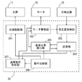
- FIG. 1 is a block diagram showing a configuration of a spectrophotometer for a chromatograph according to an embodiment.
- FIG. 2 is a schematic view showing the configuration of a diffraction grating.
- FIG. 3 is a block diagram showing a functional configuration of the detector control unit of FIG.
- FIG. 4 is a flowchart showing a reference position detection method according to the embodiment.
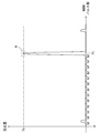
- FIG. 5 is a diagram showing an example of a change in the amount of light received by the photodetector depending on the number of control pulses given to the motor.
- FIG. 6 is an enlarged view of part A in FIG.
- FIG. 7 is a block diagram showing the configuration of a liquid chromatograph including the spectrophotometer of FIG.
- FIG. 1 is a block diagram showing a configuration of a spectrophotometer for a chromatograph according to an embodiment.
- the spectrophotometer according to this embodiment is used, for example, in a liquid chromatograph.
- the spectrophotometer 10 of FIG. 1 includes a light source 11, a dimming filter 12, a diffraction grating 13, a flow cell 14, a photodetector 15, a motor 16, and a detector control unit 30.
- the light source 11 is, for example, a deuterium lamp.
- the motor 16 rotates the diffraction grating 13.
- the spectrophotometer 10 performs a reference position detection operation and a normal operation.
- the reference position refers to the angle of the diffraction grating 13 such that light having a predetermined wavelength is guided to the photodetector 15 through the flow cell 14.
- the reference position of the diffraction grating 13 is defined as the angle of the diffraction grating 13 when the 0th-order light reflected by the diffraction grating 13 enters the photodetector 15 through the flow cell 14.
- the light generated by the light source 11 is attenuated by passing through the dimming filter 12.
- the attenuated light is guided to the diffraction grating 13 by an optical system (not shown) such as a mirror.
- the mechanism for attenuating light is not limited to the dimming filter 12, and other members or devices may be used.
- the dimming filter 12 may not be provided.
- the light generated by the light source 11 is guided to the diffraction grating 13 by the optical system without passing through the dimming filter 12.
- the diffraction grating 13 reflects the incident light so as to disperse it into light having a plurality of wavelengths.
- the light of a plurality of wavelengths reflected by the diffraction grating 13 is reflected at different angles.
- the 0th order light from the diffraction grating 13 includes light having a plurality of wavelengths. Therefore, the intensity of the 0th-order light is higher than the intensity of light of any wavelength.
- the flow cell 14 is an example of a sample cell.
- the wavelength of the light guided to the flow cell 14 changes according to the angle of the diffraction grating 13.
- the light transmitted through the flow cell 14 is guided to the photodetector 15.
- the photodetector 15 includes, for example, a photodiode and detects the intensity of incident light. The intensity of light detected by the photodetector 15 is equivalent to the amount of light received by the photodetector 15.
- the wavelength of light suitable for analysis differs depending on the type of sample. Therefore, it is necessary to adjust the angle of the diffraction grating 13 so that light having a wavelength suitable for sample analysis enters the photodetector 15 through the flow cell 14.
- the detector control unit 30 includes an input / output I / F (interface) 31, a CPU (central processing unit) 32, a RAM (random access memory) 33, a ROM (read-only memory) 34, and a storage device 35.
- the input / output I / F 31, CPU 32, RAM 33, ROM 34, and storage device 35 are connected to the bus 38.
- the storage device 35 includes a storage medium such as a semiconductor memory or a memory card, and stores a detector control program.
- the RAM 33 is used as a work area of the CPU 32.
- the system program is stored in the ROM 34.
- the CPU 32 controls the light source 11, the dimming filter 12, and the motor 16 through the input / output I / F 31 by executing the detector control program stored in the storage device 35 on the RAM 33, and outputs the output signal of the photodetector 15. Received through input / output I / F31.
- the detector control program also includes a reference position detection program. The reference position detection method described later is implemented by the CPU 32 executing the reference position detection program stored in the storage device 35 on the RAM 33.
- the input / output I / F 31 is connected to, for example, the analysis control unit 50 (FIG. 7) of the liquid chromatograph.
- FIG. 2 is a schematic diagram showing the configuration of the diffraction grating.
- the diffraction grating 13 has a diffraction grating reflecting surface 13a.
- the diffraction grating 13 is attached to the rotating shaft 16a of the motor 16 by the attachment member 13b.
- the motor 16 is a stepping motor.
- the detector control unit 30 of FIG. 1 gives a pulse signal including a control pulse and a rotation direction instruction signal indicating a rotation direction to the motor 16. Each time a control pulse is given to the motor 16, the rotation shaft 16a rotates by a constant angle in the direction indicated by the rotation direction instruction signal.
- one control pulse corresponds to a constant rotation angle of the motor 16.
- the rotation angle of the motor 16 per one control pulse is 0.009 degrees.
- the angle of the diffraction grating 13 usually does not match the reference position. In this case, it is necessary to detect the angle of the diffraction grating 13 with respect to the reference position when the power of the spectrophotometer 10 is turned off. For that purpose, it is necessary to detect the reference position with respect to the initial state of the diffraction grating 13 when the power is turned on.
- the relationship between the angle of the diffraction grating 13 with respect to the reference position and the wavelength of the light incident on the photodetector 15 is known.
- the angle of the diffraction grating 13 can be set so as to guide the light having a desired wavelength according to the sample to the photodetector 15 through the flow cell 14.
- the reference position of the diffraction grating 13 is detected by the reference position detection operation before the normal operation.
- FIG. 3 is a block diagram showing a functional configuration of the detector control unit of FIG.
- the detector control unit 30 includes a light source drive unit 301, a motor drive unit 302, a light receiving amount acquisition unit 303, a storage unit 304, a reference position detection unit 305, an operation switching unit 306, and a normal operation control unit 307. including.
- the functions of the above components (301 to 307) are realized by the CPU 32 of FIG. 1 executing a detector control program which is a computer program stored in a storage medium (recording medium) such as a storage device.
- a part or all the components of the detector control unit 30 may be realized by hardware such as an electronic circuit.
- the light source driving unit 301 turns the light source 11 on and off.
- the motor drive unit 302 gives the motor 16 a pulse signal including a control pulse and a direction indicating signal instructing the rotation direction in order to rotate the motor 16 in the forward direction or the reverse direction.
- the light receiving amount acquisition unit 303 acquires the light receiving amount of the photodetector 15 based on the output signal of the photodetector 15, and also acquires the pulse signal and the direction indicating signal from the motor drive unit 302. Further, the light receiving amount acquisition unit 303 integrates the number of control pulses included in the pulse signal. In this case, the light receiving amount acquisition unit 303 adds the number of control pulses included in the pulse signal when the rotation direction indicated by the direction indicating signal is the positive direction.
- the number of control pulses included in the pulse signal is subtracted.
- the relationship between the number of control pulses and the amount of received light can be obtained.
- the change in the amount of received light according to the change in the number of control pulses is sequentially stored in the storage unit 304.
- the reference position detection unit 305 controls the motor drive unit 302 and detects the reference position of the diffraction grating 13 based on the change in the amount of light received stored in the storage unit 304. The details of the reference position detection method will be described later.
- the operation switching unit 306 switches between the reference position detection operation and the normal operation. Further, the operation switching unit 306 inserts the dimming filter 12 into the optical path between the light source 11 and the diffraction grating 13 during the reference position detection operation, and inserts the dimming filter 12 between the light source 11 and the diffraction grating 13 during normal operation. Exclude from the optical path of. When the amount of light of the light source 11 is small, the dimming filter 12 may not be provided.
- the normal operation control unit 307 adjusts the angle of the diffraction grating 13 from the reference position by controlling the motor 16 based on the reference position stored in the storage unit 304. In this case, the normal operation control unit 307 adjusts the angle of the diffraction grating 13 so that the light having the wavelength corresponding to the sample is guided to the photodetector 15 through the flow cell 14.
- FIG. 4 is a flowchart showing a reference position detection method according to the embodiment.
- FIG. 5 is a diagram showing an example of a change in the amount of light received by the photodetector 15 depending on the number of control pulses given to the motor 16.
- FIG. 6 is an enlarged view of part A in FIG.
- the vertical axis of FIGS. 5 and 6 shows the amount of light received by the photodetector 15, and the horizontal axis shows the number of control pulses given to the motor 16.
- the number of control pulses in FIGS. 5 and 6 is added when the motor 16 rotates in the forward direction and subtracted when the motor 16 rotates in the opposite direction. As shown in FIGS.
- the threshold value Th for detecting the peak of the 0th order light is set in advance.
- the threshold value Th is smaller than the peak value (maximum value) of the received amount of the 0th-order light guided from the diffraction grating 13 to the photodetector 15 through the flow cell 14, and the threshold value Th is of light other than the 0th-order light. It is set larger than the amount of light received.
- the reference position detection method of FIG. 4 is carried out by executing the reference position detection program.
- the operation switching unit 306 determines whether or not the power of the spectrophotometer 10 is turned on (step S1). When the power is turned on, the light source driving unit 301 turns on the light source 11 (step S2). In this state, the operation switching unit 306 instructs the reference position detection unit 305 to perform the reference position detection operation, and inserts the dimming filter 12 into the optical path in the optical path between the light source 11 and the diffraction grating 13 (Ste S3).
- the motor drive unit 302 applies M control pulses to the motor 16 to rotate the diffraction grating 13 in the positive direction by a first angle (step S4).
- M is, for example, 20.
- the control pulse number M is set so that the first angle is smaller than the width of the peak of the 0th-order light at the intersection of the peak of the 0th-order light and the threshold value Th.
- the light receiving amount acquisition unit 303 acquires the light receiving amount of the photodetector 15 based on the output signal of the photodetector 15 (step S5).
- the light-receiving amount acquired by the light-receiving amount acquisition unit 303 is stored in the storage unit 304.
- the reference position detection unit 305 determines whether or not the amount of light received stored in the storage unit 304 is equal to or greater than a preset threshold value Th (step S6).
- Th the motor drive unit 302 returns to step S4 and applies M control pulses to the motor 16 to make the diffraction grating 13 a first angle in the positive direction. Rotate.
- steps S4 to S6 are repeated until the amount of received light becomes equal to or higher than the threshold value Th.
- the coarse adjustment of the diffraction grating 13 is performed so that the angle of the diffraction grating 13 approaches the reference position.
- the motor drive unit 302 applies K control pulses to the motor 16 to rotate the diffraction grating 13 by a third angle in the opposite direction (Ste S7).
- the number of K is, for example, half of M, and 10 in this example.
- the amount of light received when the diffraction grating 13 is rotated in the positive direction by an angle corresponding to the control pulse number P1 from the initial state is the threshold value Th or more.
- the rotation angle of the diffraction grating 13 exceeds the angle at which the light receiving amount reaches the peak value.
- the diffraction grating 13 returns from the angle corresponding to the control pulse number P1 in the opposite direction by the angle corresponding to the control pulse number K.
- the angle of the diffraction grating 13 becomes an angle corresponding to the control pulse number P2 from the initial state.
- the rotation angle of the diffraction grating 13 is smaller than the angle at which the light receiving amount reaches the peak value.
- N is smaller than M and K, for example 1.
- the light receiving amount acquisition unit 303 acquires the light receiving amount of the photodetector 15 based on the output signal of the photodetector 15 (step S9).
- the light-receiving amount acquired by the light-receiving amount acquisition unit 303 is stored in the storage unit 304.
- the reference position detection unit 305 determines whether or not the peak value of the received light amount stored in the storage unit 304 has been detected (step S10).
- the motor driving unit 302 returns to step S8 and applies N control pulses to the motor 16 to further rotate the diffraction grating 13 in the positive direction by a second angle.
- the processes of steps S8 to S10 are repeated until the peak value of the received light amount is detected.
- control pulses are given to the motor 16 one by one from a state where the angle of the diffraction grating 13 is an angle corresponding to the number of control pulses P2, and the diffraction grating 13 rotates by a third angle.
- the amount of light received gradually increases, and when the angle of the diffraction grating 13 is an angle corresponding to the number of control pulses P3, the amount of light received becomes the peak value (maximum value) Pe.
- the amount of light received decreases when the angle of the diffraction grating 13 is rotated to an angle corresponding to the number of control pulses P4.
- the received light amount reaches the peak value Pe at the angle corresponding to the control pulse number P3 before the angle corresponding to the control pulse number P4.
- the method for determining whether or not the peak value Pe of the received light amount is detected is not limited to the above method, and other methods may be used.
- the reference position detection unit 305 stores the number of control pulses corresponding to the peak value of the received light amount in the storage unit 304 as the reference position (step S11).
- the control pulse number P3 is stored in the storage unit 304 as a reference position. The control pulse corresponding to the reference position is accurately detected by the processing of steps S8 to S10.
- the operation switching unit 306 instructs the normal operation control unit 307 to perform the normal operation.
- the storage unit 304 stores in advance the relationship between the rotation angle of the diffraction grating 13 from the reference position and the wavelength.
- the number of control pulses given to the motor 16 after the power of the spectrophotometer is turned on is normally given to the operation control unit 307.
- the normal operation control unit 307 calculates, for example, the difference between the number of control pulses given to the motor 16 and the number of control pulses corresponding to the reference position, and the difference in the number of control pulses corresponds to the wavelength specified according to the sample.
- the motor 16 is rotated by the motor drive unit 302 so as to do so. As a result, among the light generated by the light source 11, light having a specified wavelength is guided to the photodetector 15 through the flow cell 14.
- FIG. 7 is a block diagram showing the configuration of a liquid chromatograph including the spectrophotometer 10 of FIG.
- the liquid chromatograph 100 of FIG. 7 includes a pump 110 for a mobile phase, a sample introduction unit 120, an introduction port 130, an analysis column 140, a column oven 150, and a spectrophotometer 10.
- the analysis column 140 is provided in the column oven 150.
- the column oven 150 maintains the analytical column 140 at a set temperature.
- the pump 110 sucks the mobile phase (eluent) in the mobile phase container 111 and supplies it to the analysis column 140.
- the sample introduction unit 120 includes, for example, an autosampler or an injector, and introduces the sample to be analyzed into the mobile phase at the introduction port 130.
- the mobile phase and the sample that have passed through the analysis column 140 flow through the flow cell 14 (see FIG. 1) of the spectrophotometer 10, and are discharged to the waste liquid container 112.
- the liquid chromatograph 100 includes an analysis control unit 50, an operation unit 51, and a display unit 52.
- the operation unit 51 is used by the user to give various commands to the analysis control unit 50.
- the analysis control unit 50 controls the pump 110, the sample introduction unit 120, the column oven 150, and the spectrophotometer 10. Further, the analysis control unit 50 generates a chromatogram based on the output signal of the spectrophotometer 10. The generated chromatogram is displayed on the display unit 52.
- the motor 16 when the light receiving amount of the photodetector 15 becomes the threshold value Th or more, the motor 16 is rotated in the opposite direction by a third angle. Therefore, even when the first angle is set to be relatively large, it is possible to detect the rotation angle of the motor 16 in which the peak value of the light receiving amount of the photodetector 15 appears. As a result, the reference position of the diffraction grating 13 can be detected in a short time.
- the reference position of the diffraction grating 13 can be detected more accurately based on the amount of received 0th-order light having the highest intensity.
- the first angle is set to be smaller than the angle corresponding to the peak width at the intersection of the peak of the 0th-order light guided from the diffraction grating 13 to the photodetector 15 through the flow cell 14 and the threshold value Th.
- the angle at which the received light amount is equal to or higher than the threshold value Th is not detected, it is not necessary to perform processing such as resetting the first angle to a small value. As a result, the reference position of the diffraction grating 13 can be reliably detected in a short time.
- the angle of the diffraction grating 13 corresponding to the number of control pulses in which the peak of the 0th order light from the diffraction grating 13 appears is detected as the reference position, but this is the reference position. Not limited to.
- the angle of the diffraction grating 13 at which the peak of a specific wavelength obtained when the diffraction grating 13 is rotated may appear may be detected as the reference position.
- the motor 16 is rotated in the reverse direction of the third angle when the light receiving amount of the photodetector 15 becomes equal to or higher than the threshold value Th due to the rotation of the motor 16 in the forward direction by the first angle.
- the motor 16 it is not always necessary for the motor 16 to be rotated in the opposite direction by a third angle.
- the angle of the diffraction grating 13 may not exceed the angle corresponding to the peak value due to the rotation of the motor 16 in the positive direction of the first angle.
- the motor 16 may not be rotated in the reverse direction and the diffraction grating 13 may be finely adjusted.
- the threshold value Th is set to be smaller than the maximum value of the received amount of the 0th-order light and larger than the received amount of the 0th-order light, but the threshold value Th is not limited to this.
- the threshold value Th is larger than the peak value of the received amount of light having a specific wavelength. It may be set to be smaller and larger than the amount of received light having other wavelengths.
- the number of control pulses M corresponding to the first angle is set to be smaller than the number of control pulses corresponding to the peak width at the intersection of the peak of the amount of received light of the 0th order light and the threshold value Th.
- the control pulse number M is not limited to this.
- the control pulse number M is initially set large, and when the diffraction grating 13 is rotating within a certain angle range, the control pulse number M is reduced when the received light amount does not exceed the threshold value Th. Processing may be performed.
- the motor 16 may be rotated once during the reference position detection operation, or may be rotated within a predetermined angle range. Further, a mechanism using a motor, a belt and a pulley may be used to rotate the diffraction grating 13.
- the spectrophotometer 10 is used for the liquid chromatograph 100, but the spectrophotometer 10 may be used for other chromatographs such as a supercritical chromatograph.
- the light source 11 is a deuterium lamp, but the light source 11 may be another lamp such as a tungsten lamp or another light emitting element such as a light emitting diode.
- the spectrophotometer for chromatograph is Light source and A diffraction grating that disperses the light generated by the light source into light of a plurality of different wavelengths, A motor that changes the angle of the diffraction grating and A sample cell that receives light of one of a plurality of wavelengths dispersed by the diffraction grating, and A photodetector that detects the light that passes through the sample cell, The motor is rotated in the first direction by a first angle until the light receiving amount of the light detector becomes equal to or higher than a predetermined threshold value, and the light receiving amount of the light detector becomes equal to or higher than the threshold value.
- a reference position detecting unit for detecting a reference position corresponding to the reference angle of the diffraction grid may be provided.
- the motor is rotated in the first direction by a first angle until the amount of light received by the photodetector exceeds a predetermined threshold value.
- the diffraction grating is adjusted close to the reference position in a short time.
- the motor is rotated by a second angle smaller than the first angle, so that the rotation angle of the motor at which the peak of the light receiving amount of the photodetector appears is detected.
- the reference position of the diffraction grating is accurately detected.
- the reference position detection unit makes the motor smaller than the first angle and larger than the second angle by a third angle when the amount of light received by the photodetector exceeds the threshold value. After rotating in the second direction opposite to the first direction, the motor may be rotated by the second angle.
- the spectrophotometer for chromatograph described in the second item, it is possible to detect the rotation angle of the motor in which the peak of the received light amount of the photodetector appears even when the first angle is set relatively large. It becomes. Thereby, the reference position can be detected in a shorter time.
- the reference position of the diffraction grating can be detected more accurately based on the intensity of the 0th-order light having the highest intensity.
- the first angle is the 0th order light guided from the diffraction grating to the photodetector through the sample cell. It may be smaller than the angle corresponding to the peak width at the intersection of the peak of the received light amount and the threshold value.
- the amount of light received is limited between the time point before the rotation of the first angle of the diffraction grating and the time point after the rotation of the first angle of the diffraction grating.
- the situation that exceeds the value does not occur.
- the reference position detection method is a reference position detection method for detecting a reference position corresponding to a reference angle of a diffraction grating in a spectrophotometer.
- the step of detecting the rotation angle of the diffraction grating and It may include a step of detecting the reference position based on the detected rotation angle.
- the diffraction grating is rotated in the first direction by a first angle until the amount of light received by the photodetector becomes equal to or higher than a predetermined threshold value.
- the diffraction grating is adjusted close to the reference position in a short time.
- the diffraction grating is rotated by a second angle smaller than the first angle, so that the rotation angle of the diffraction grating at which the peak of the light receiving amount of the photodetector appears is detected.
- the reference position of the diffraction grating is accurately detected.
Abstract
A diffraction lattice in this chromatographic spectrophotometer disperses light that has been generated by a light source into light having a plurality of different wavelengths. A sample cell receives light of any one of the wavelengths among the plurality of wavelengths of the light dispersed by the diffraction lattice. A photodetector detects light transmitting through the sample cell. A reference position detection unit: causes a motor to rotate in a first direction by a first angle until the amount of light received by the photodetector reaches or exceeds a predetermined threshold value, and then causes the motor to rotate by a second angle that is smaller than the first angle after the amount of light received by the photodetector has reached or exceeded the threshold value, and thereby detects a rotation angle of the motor at which a peak amount of light received by the photodetector appears; and detects a reference position corresponding to a reference angle of the diffraction lattice on the basis of the detected rotation angle.
Description
本発明は、クロマトグラフ用分光光度計および基準位置検出方法に関する。
The present invention relates to a spectrophotometer for a chromatograph and a reference position detection method.
分光光度計は、例えば液体クロマトグラフにおいて分析カラムで分離された試料の成分を検出するために使用されている。分光光度計は、光源、回折格子、フローセルおよび光検出器を備える。
A spectrophotometer is used, for example, in a liquid chromatograph to detect the components of a sample separated by an analytical column. The spectrophotometer includes a light source, a diffraction grating, a flow cell and a photodetector.
このような分光光度計では、例えば、光源により発生された光が回折格子により異なる波長を有する複数の光に分散される。分散された複数の光のうち、特定の波長を有する光がフローセルに導かれる。フローセルを透過した光は光検出器により検出される。この場合、分析対象である試料に応じて適切な波長が異なる。そのため、モータにより回折格子の角度が調整されることにより、試料の分析に適切な波長の光がフローセルに入射する。ここで、回折格子が予め定められた基準角度(以下、基準位置と呼ぶ。)にあるときに回折格子によりフローセルに導かれる光の波長は既知である。また、基準位置からの回折格子の回転角度とフローセルに入射する光の波長との関係も既知である。したがって、基準位置からの回折格子の回転角度を調整することにより、フローセルに所望の波長の光を導くことができる。
In such a spectrophotometer, for example, the light generated by the light source is dispersed by a diffraction grating into a plurality of lights having different wavelengths. Of the plurality of dispersed lights, light having a specific wavelength is guided to the flow cell. The light transmitted through the flow cell is detected by a photodetector. In this case, the appropriate wavelength differs depending on the sample to be analyzed. Therefore, the angle of the diffraction grating is adjusted by the motor, so that light having a wavelength suitable for sample analysis is incident on the flow cell. Here, the wavelength of light guided to the flow cell by the diffraction grating when the diffraction grating is at a predetermined reference angle (hereinafter referred to as a reference position) is known. The relationship between the rotation angle of the diffraction grating from the reference position and the wavelength of the light incident on the flow cell is also known. Therefore, by adjusting the rotation angle of the diffraction grating from the reference position, light of a desired wavelength can be guided to the flow cell.
一方、分光光度計の電源がオフされたときには、モータの回転軸は任意の角度で停止する。したがって、回折格子は基準位置で停止するとは限らない。
On the other hand, when the power of the spectrophotometer is turned off, the rotation axis of the motor stops at an arbitrary angle. Therefore, the diffraction grating does not always stop at the reference position.
特許文献1に記載の分光光度計では、回折格子(グレーティング)の近傍に回折格子がホームポジションにあることを検知するホームポジションセンサが設けられている。ホームポジションセンサは、例えばマイクロスイッチである。分光光度計の電源がオフになると、回折格子がホームポジションにあることをホームポジションセンサが検知するまで、モータが回折格子を一定パルス分ずつ回転させる。その後、モータは所定パルス分だけ回折格子を反対方向に回転させる。分光光度計の電源がオンになると、回折格子がホームポジションにあることをホームポジションセンサが検知するまで、モータが1パルス分ずつ回折格子を回転させる。
特開2018-13412号公報
In the spectrophotometer described in Patent Document 1, a home position sensor for detecting that the diffraction grating is in the home position is provided in the vicinity of the diffraction grating (grating). The home position sensor is, for example, a microswitch. When the spectrophotometer is turned off, the motor rotates the grating by a constant pulse until the home position sensor detects that the grating is in the home position. After that, the motor rotates the diffraction grating in the opposite direction by a predetermined pulse. When the spectrophotometer is turned on, the motor rotates the grating by one pulse until the home position sensor detects that the grating is in the home position.
JP-A-2018-13412
特許文献1に記載の分光光度計では、回折格子をホームポジションに位置決めするためにホームポジションセンサが必要である。回折格子の取り付け部材に突起が設けられ、ホームポジションセンサとして、突起を検出するフォトインタラプタが用いられることもある。これらの場合、ホームポジションセンサによる部品コストが必要になるとともに、ホームポジションセンサを取り付けるための製造コストが必要となる。
The spectrophotometer described in Patent Document 1 requires a home position sensor in order to position the diffraction grating at the home position. A protrusion is provided on the mounting member of the diffraction grating, and a photo interrupter for detecting the protrusion may be used as the home position sensor. In these cases, the cost of parts for the home position sensor is required, and the manufacturing cost for mounting the home position sensor is required.
本発明の目的は、回折格子の基準位置を検出するためのコストの低減を可能とする分光光度計および基準位置検出方法を提供することである。
An object of the present invention is to provide a spectrophotometer and a reference position detection method capable of reducing the cost for detecting a reference position of a diffraction grating.
本発明の一局面に従うクロマトグラフ用分光光度計は、光源と、前記光源により発生された光を異なる複数の波長の光に分散させる回折格子と、前記回折格子の角度を変化させるモータと、前記回折格子により分散された複数の波長の光のうちいずれかの波長の光を受ける試料セルと、前記試料セルを透過する光を検出する光検出器と、前記光検出器の受光量が予め定められたしきい値以上になるまで前記モータを第1の方向に第1の角度ずつ回転させ、前記光検出器の受光量が前記しきい値以上になった後に、前記モータを前記第1の角度よりも小さい第2の角度ずつ回転させることにより前記光検出器の受光量のピークが現れる前記モータの回転角度を検出し、検出された回転角度に基づいて前記回折格子の基準の角度に相当する基準位置を検出する基準位置検出部とを備える。
The spectrophotometer for chromatograph according to one aspect of the present invention includes a light source, a diffraction grid that disperses the light generated by the light source into light having a plurality of different wavelengths, a motor that changes the angle of the diffraction grid, and the above. A sample cell that receives light of one of a plurality of wavelengths dispersed by a diffraction grid, a light detector that detects light transmitted through the sample cell, and a light receiving amount of the light detector are predetermined. The motor is rotated in the first direction by a first angle until the threshold value is exceeded, and after the amount of light received by the light detector is equal to or higher than the threshold value, the motor is moved to the first position. The rotation angle of the motor in which the peak of the light receiving amount of the light detector appears by rotating by a second angle smaller than the angle is detected, and the rotation angle corresponds to the reference angle of the diffraction grid based on the detected rotation angle. It is provided with a reference position detecting unit for detecting a reference position to be used.
本発明の他の局面に従う基準位置検出方法は、分光光度計において回折格子の基準の角度に相当する基準位置を検出する基準位置検出方法であって、前記分光光度計において光源により光を発生させるステップと、前記光源により発生された光を回折格子により異なる複数の波長の光に分散させ、前記分散された複数の波長の光のうちいずれかの波長の光を試料セルを通して光検出器に導くステップと、前記光検出器の受光量が予め定められたしきい値以上になるまで前記回折格子を第1の方向に第1の角度ずつ回転させるステップと、前記光検出器の受光量が前記しきい値以上になった後に、前記回折格子を前記第1の角度よりも小さい第2の角度ずつ回転させることにより前記光検出器の受光量のピークが現れる前記回折格子の回転角度を検出するステップと、前記検出された回転角度に基づいて前記基準位置を検出するステップとを含む。
The reference position detection method according to another aspect of the present invention is a reference position detection method for detecting a reference position corresponding to a reference angle of a diffraction grating in a spectrophotometer, and the spectrophotometer generates light by a light source. In the step, the light generated by the light source is dispersed by a diffraction grating into light having a plurality of different wavelengths, and the light having one of the dispersed wavelengths is guided to the light detector through the sample cell. The step, the step of rotating the diffraction grating in the first direction by a first angle until the light receiving amount of the light detector becomes equal to or higher than a predetermined threshold value, and the light receiving amount of the light detector are described. After the threshold is exceeded, the diffraction grating is rotated by a second angle smaller than the first angle to detect the rotation angle of the diffraction grating at which the peak of the light receiving amount of the light detector appears. The step includes a step of detecting the reference position based on the detected rotation angle.
本発明によれば、分光光度計における回折格子の基準位置を検出するためのコストの低減が可能となる。
According to the present invention, it is possible to reduce the cost for detecting the reference position of the diffraction grating in the spectrophotometer.
以下、実施の形態に係るクロマトグラフ用分光光度計および基準位置検出方法について図面を参照しながら詳細に説明する。
Hereinafter, the spectrophotometer for chromatograph and the reference position detection method according to the embodiment will be described in detail with reference to the drawings.
(1)分光光度計の構成
図1は一実施の形態に係るクロマトグラフ用分光光度計の構成を示すブロック図である。本実施の形態に係る分光光度計は、例えば液体クロマトグラフに用いられる。 (1) Configuration of Spectrophotometer FIG. 1 is a block diagram showing a configuration of a spectrophotometer for a chromatograph according to an embodiment. The spectrophotometer according to this embodiment is used, for example, in a liquid chromatograph.
図1は一実施の形態に係るクロマトグラフ用分光光度計の構成を示すブロック図である。本実施の形態に係る分光光度計は、例えば液体クロマトグラフに用いられる。 (1) Configuration of Spectrophotometer FIG. 1 is a block diagram showing a configuration of a spectrophotometer for a chromatograph according to an embodiment. The spectrophotometer according to this embodiment is used, for example, in a liquid chromatograph.
図1の分光光度計10は、光源11、減光フィルタ12、回折格子13、フローセル14、光検出器15、モータ16および検出器制御部30を含む。本実施の形態では、光源11は、例えば重水素ランプである。モータ16は、回折格子13を回転させる。本実施の形態では、分光光度計10は、基準位置検出動作および通常動作を行う。ここで、基準位置とは、予め定められた波長の光がフローセル14を通して光検出器15に導かれるような回折格子13の角度をいう。本実施の形態では、回折格子13の基準位置は、回折格子13により反射される0次光がフローセル14を通して光検出器15に入射するときの回折格子13の角度と定義される。
The spectrophotometer 10 of FIG. 1 includes a light source 11, a dimming filter 12, a diffraction grating 13, a flow cell 14, a photodetector 15, a motor 16, and a detector control unit 30. In this embodiment, the light source 11 is, for example, a deuterium lamp. The motor 16 rotates the diffraction grating 13. In the present embodiment, the spectrophotometer 10 performs a reference position detection operation and a normal operation. Here, the reference position refers to the angle of the diffraction grating 13 such that light having a predetermined wavelength is guided to the photodetector 15 through the flow cell 14. In the present embodiment, the reference position of the diffraction grating 13 is defined as the angle of the diffraction grating 13 when the 0th-order light reflected by the diffraction grating 13 enters the photodetector 15 through the flow cell 14.
基準位置検出動作時には、光源11により発生された光は、減光フィルタ12を通過することにより減衰される。減衰された光は、ミラー等の光学系(図示せず)により回折格子13に導かれる。なお、光を減衰させる機構は、減光フィルタ12に限定されず、他の部材又は装置等を用いてもよい。なお、光源11の光量が小さい場合には、減光フィルタ12が設けられなくてもよい。一方、通常動作時には、光源11により発生された光は、減光フィルタ12を通過せずに光学系により回折格子13に導かれる。回折格子13は、入射光を複数の波長の光に分散させるように反射する。この場合、回折格子13により反射される複数の波長の光はそれぞれ異なる角度に反射される。回折格子13からの0次光は複数の波長の光を含む。したがって、0次光の強度は、いずれの波長の光の強度よりも高い。
During the reference position detection operation, the light generated by the light source 11 is attenuated by passing through the dimming filter 12. The attenuated light is guided to the diffraction grating 13 by an optical system (not shown) such as a mirror. The mechanism for attenuating light is not limited to the dimming filter 12, and other members or devices may be used. When the amount of light of the light source 11 is small, the dimming filter 12 may not be provided. On the other hand, during normal operation, the light generated by the light source 11 is guided to the diffraction grating 13 by the optical system without passing through the dimming filter 12. The diffraction grating 13 reflects the incident light so as to disperse it into light having a plurality of wavelengths. In this case, the light of a plurality of wavelengths reflected by the diffraction grating 13 is reflected at different angles. The 0th order light from the diffraction grating 13 includes light having a plurality of wavelengths. Therefore, the intensity of the 0th-order light is higher than the intensity of light of any wavelength.
回折格子13により分散された光のうちいずれかの波長を有する光がミラー等の光学系(図示せず)によりフローセル14に導かれる。フローセル14は、試料セルの例である。回折格子13の角度に応じてフローセル14に導かれる光の波長が変化する。フローセル14には、例えば液体クロマトグラフの分析カラム(分離カラム)から供給される移動相および試料が流れる。フローセル14を透過した光は光検出器15に導かれる。光検出器15は、例えばフォトダイオードを含み、入射した光の強度を検出する。光検出器15により検出される光の強度は光検出器15の受光量と等価である。
Light having any wavelength among the light dispersed by the diffraction grating 13 is guided to the flow cell 14 by an optical system (not shown) such as a mirror. The flow cell 14 is an example of a sample cell. The wavelength of the light guided to the flow cell 14 changes according to the angle of the diffraction grating 13. The mobile phase and the sample supplied from the analysis column (separation column) of the liquid chromatograph, for example, flow through the flow cell 14. The light transmitted through the flow cell 14 is guided to the photodetector 15. The photodetector 15 includes, for example, a photodiode and detects the intensity of incident light. The intensity of light detected by the photodetector 15 is equivalent to the amount of light received by the photodetector 15.
試料の種類により分析に適した光の波長が異なる。したがって、試料の分析に適した波長の光がフローセル14を通して光検出器15に入射するように回折格子13の角度を調整する必要がある。
The wavelength of light suitable for analysis differs depending on the type of sample. Therefore, it is necessary to adjust the angle of the diffraction grating 13 so that light having a wavelength suitable for sample analysis enters the photodetector 15 through the flow cell 14.
検出器制御部30は、入出力I/F(インタフェース)31、CPU(中央演算処理装置)32、RAM(ランダムアクセスメモリ)33、ROM(リードオンリメモリ)34および記憶装置35を含む。入出力I/F31、CPU32、RAM33、ROM34および記憶装置35はバス38に接続されている。
The detector control unit 30 includes an input / output I / F (interface) 31, a CPU (central processing unit) 32, a RAM (random access memory) 33, a ROM (read-only memory) 34, and a storage device 35. The input / output I / F 31, CPU 32, RAM 33, ROM 34, and storage device 35 are connected to the bus 38.
記憶装置35は、半導体メモリまたはメモリカード等の記憶媒体を含み、検出器制御プログラムを記憶する。RAM33は、CPU32の作業領域として用いられる。ROM34にはシステムプログラムが記憶される。CPU32は、記憶装置35に記憶された検出器制御プログラムをRAM33上で実行することにより入出力I/F31を通して光源11、減光フィルタ12およびモータ16を制御するとともに光検出器15の出力信号を入出力I/F31を通して受ける。また、検出器制御プログラムは、基準位置検出プログラムを含む。CPU32が記憶装置35に記憶された基準位置検出プログラムをRAM33上で実行することにより後述する基準位置検出方法が実施される。入出力I/F31は、例えば液体クロマトグラフの分析制御部50(図7)に接続される。
The storage device 35 includes a storage medium such as a semiconductor memory or a memory card, and stores a detector control program. The RAM 33 is used as a work area of the CPU 32. The system program is stored in the ROM 34. The CPU 32 controls the light source 11, the dimming filter 12, and the motor 16 through the input / output I / F 31 by executing the detector control program stored in the storage device 35 on the RAM 33, and outputs the output signal of the photodetector 15. Received through input / output I / F31. The detector control program also includes a reference position detection program. The reference position detection method described later is implemented by the CPU 32 executing the reference position detection program stored in the storage device 35 on the RAM 33. The input / output I / F 31 is connected to, for example, the analysis control unit 50 (FIG. 7) of the liquid chromatograph.
(2)回折格子の構成および動作
図2は回折格子の構成を示す模式図である。図2に示されるように、回折格子13は、回折格子反射面13aを有する。回折格子13は、取り付け部材13bによりモータ16の回転軸16aに取り付けられる。本実施の形態では、モータ16はステッピングモータである。図1の検出器制御部30がモータ16に制御パルスを含むパルス信号および回転方向を指示する回転方向指示信号を与える。モータ16に制御パルスが与えられるごとに回転方向指示信号により指示された方向に回転軸16aが一定角度ずつ回転する。それにより、回折格子13が矢印Rで示すように正方向または逆方向に一定角度ずつ回転する。この場合、1つの制御パルスがモータ16の一定の回転角度に対応する。例えば、40000個の制御パルスが与えられることによりモータ16が1回転する場合、1つの制御パルス当たりのモータ16の回転角度は0.009度である。 (2) Configuration and operation of the diffraction grating FIG. 2 is a schematic diagram showing the configuration of the diffraction grating. As shown in FIG. 2, thediffraction grating 13 has a diffraction grating reflecting surface 13a. The diffraction grating 13 is attached to the rotating shaft 16a of the motor 16 by the attachment member 13b. In this embodiment, the motor 16 is a stepping motor. The detector control unit 30 of FIG. 1 gives a pulse signal including a control pulse and a rotation direction instruction signal indicating a rotation direction to the motor 16. Each time a control pulse is given to the motor 16, the rotation shaft 16a rotates by a constant angle in the direction indicated by the rotation direction instruction signal. As a result, the diffraction grating 13 rotates in the forward direction or the reverse direction by a constant angle as indicated by the arrow R. In this case, one control pulse corresponds to a constant rotation angle of the motor 16. For example, when the motor 16 makes one rotation by giving 40,000 control pulses, the rotation angle of the motor 16 per one control pulse is 0.009 degrees.
図2は回折格子の構成を示す模式図である。図2に示されるように、回折格子13は、回折格子反射面13aを有する。回折格子13は、取り付け部材13bによりモータ16の回転軸16aに取り付けられる。本実施の形態では、モータ16はステッピングモータである。図1の検出器制御部30がモータ16に制御パルスを含むパルス信号および回転方向を指示する回転方向指示信号を与える。モータ16に制御パルスが与えられるごとに回転方向指示信号により指示された方向に回転軸16aが一定角度ずつ回転する。それにより、回折格子13が矢印Rで示すように正方向または逆方向に一定角度ずつ回転する。この場合、1つの制御パルスがモータ16の一定の回転角度に対応する。例えば、40000個の制御パルスが与えられることによりモータ16が1回転する場合、1つの制御パルス当たりのモータ16の回転角度は0.009度である。 (2) Configuration and operation of the diffraction grating FIG. 2 is a schematic diagram showing the configuration of the diffraction grating. As shown in FIG. 2, the
試料の分析が行われた後に、分光光度計10の電源がオフされると、通常、回折格子13の角度は基準位置とは一致していない。この場合、分光光度計10の電源がオフされたときに、基準位置に対する回折格子13の角度を検出する必要がある。そのためには、電源オン時の回折格子13の初期状態に対する基準位置を検出する必要がある。基準位置に対する回折格子13の角度と光検出器15に入射する光の波長との関係は既知である。したがって、基準位置が検出されると、試料に応じて所望の波長の光をフローセル14を通して光検出器15に導くように回折格子13の角度を設定することができる。本実施の形態では、通常動作前の基準位置検出動作により回折格子13の基準位置が検出される。
When the power of the spectrophotometer 10 is turned off after the sample is analyzed, the angle of the diffraction grating 13 usually does not match the reference position. In this case, it is necessary to detect the angle of the diffraction grating 13 with respect to the reference position when the power of the spectrophotometer 10 is turned off. For that purpose, it is necessary to detect the reference position with respect to the initial state of the diffraction grating 13 when the power is turned on. The relationship between the angle of the diffraction grating 13 with respect to the reference position and the wavelength of the light incident on the photodetector 15 is known. Therefore, when the reference position is detected, the angle of the diffraction grating 13 can be set so as to guide the light having a desired wavelength according to the sample to the photodetector 15 through the flow cell 14. In the present embodiment, the reference position of the diffraction grating 13 is detected by the reference position detection operation before the normal operation.
(3)検出器制御部の機能的な構成
図3は図1の検出器制御部の機能的な構成を示すブロック図である。図3に示すように、検出器制御部30は、光源駆動部301、モータ駆動部302、受光量取得部303、記憶部304、基準位置検出部305、動作切替部306および通常動作制御部307を含む。上記の構成要素(301~307)の機能は、図1のCPU32が記憶装置等の記憶媒体(記録媒体)に記憶されたコンピュータプログラムである検出器制御プログラムを実行することにより実現される。なお、検出器制御部30の一部または全ての構成要素が電子回路等のハードウェアにより実現されてもよい。 (3) Functional Configuration of Detector Control Unit FIG. 3 is a block diagram showing a functional configuration of the detector control unit of FIG. As shown in FIG. 3, thedetector control unit 30 includes a light source drive unit 301, a motor drive unit 302, a light receiving amount acquisition unit 303, a storage unit 304, a reference position detection unit 305, an operation switching unit 306, and a normal operation control unit 307. including. The functions of the above components (301 to 307) are realized by the CPU 32 of FIG. 1 executing a detector control program which is a computer program stored in a storage medium (recording medium) such as a storage device. A part or all the components of the detector control unit 30 may be realized by hardware such as an electronic circuit.
図3は図1の検出器制御部の機能的な構成を示すブロック図である。図3に示すように、検出器制御部30は、光源駆動部301、モータ駆動部302、受光量取得部303、記憶部304、基準位置検出部305、動作切替部306および通常動作制御部307を含む。上記の構成要素(301~307)の機能は、図1のCPU32が記憶装置等の記憶媒体(記録媒体)に記憶されたコンピュータプログラムである検出器制御プログラムを実行することにより実現される。なお、検出器制御部30の一部または全ての構成要素が電子回路等のハードウェアにより実現されてもよい。 (3) Functional Configuration of Detector Control Unit FIG. 3 is a block diagram showing a functional configuration of the detector control unit of FIG. As shown in FIG. 3, the
光源駆動部301は、光源11をオンおよびオフする。モータ駆動部302は、モータ16を正方向または逆方向に回転させるために制御パルスを含むパルス信号および回転方向を指示する方向指示信号をモータ16に与える。受光量取得部303は、光検出器15の出力信号に基づいて、光検出器15の受光量を取得するとともに、モータ駆動部302からパルス信号および方向指示信号を取得する。また、受光量取得部303は、パルス信号に含まれる制御パルスの数を積算する。この場合、受光量取得部303は、方向指示信号により指示された回転方向が正方向である場合には、パルス信号に含まれる制御パルスの数を加算する。また、方向指示信号により指示された回転方向が逆方向である場合には、パルス信号に含まれる制御パルスの数を減算する。これにより、制御パルス数と受光量との関係が求められる。制御パルス数の変化に応じた受光量の変化は、記憶部304に順次記憶される。
The light source driving unit 301 turns the light source 11 on and off. The motor drive unit 302 gives the motor 16 a pulse signal including a control pulse and a direction indicating signal instructing the rotation direction in order to rotate the motor 16 in the forward direction or the reverse direction. The light receiving amount acquisition unit 303 acquires the light receiving amount of the photodetector 15 based on the output signal of the photodetector 15, and also acquires the pulse signal and the direction indicating signal from the motor drive unit 302. Further, the light receiving amount acquisition unit 303 integrates the number of control pulses included in the pulse signal. In this case, the light receiving amount acquisition unit 303 adds the number of control pulses included in the pulse signal when the rotation direction indicated by the direction indicating signal is the positive direction. When the rotation direction indicated by the direction instruction signal is opposite, the number of control pulses included in the pulse signal is subtracted. As a result, the relationship between the number of control pulses and the amount of received light can be obtained. The change in the amount of received light according to the change in the number of control pulses is sequentially stored in the storage unit 304.
基準位置検出部305は、モータ駆動部302を制御するとともに、記憶部304に記憶された受光量の変化に基づいて回折格子13の基準位置を検出する。基準位置検出方法の詳細については後述する。動作切替部306は、基準位置検出動作と通常動作とを切り替える。また、動作切替部306は、基準位置検出動作時に減光フィルタ12を光源11と回折格子13との間の光路に挿入し、通常動作時に減光フィルタ12を光源11と回折格子13との間の光路から除外する。なお、光源11の光量が小さい場合には、減光フィルタ12が設けられなくてもよい。通常動作制御部307は、記憶部304に記憶された基準位置に基づいて、モータ16を制御することにより基準位置からの回折格子13の角度を調整する。この場合、通常動作制御部307は、試料に応じた波長の光がフローセル14を通して光検出器15に導かれるように、回折格子13の角度を調整する。
The reference position detection unit 305 controls the motor drive unit 302 and detects the reference position of the diffraction grating 13 based on the change in the amount of light received stored in the storage unit 304. The details of the reference position detection method will be described later. The operation switching unit 306 switches between the reference position detection operation and the normal operation. Further, the operation switching unit 306 inserts the dimming filter 12 into the optical path between the light source 11 and the diffraction grating 13 during the reference position detection operation, and inserts the dimming filter 12 between the light source 11 and the diffraction grating 13 during normal operation. Exclude from the optical path of. When the amount of light of the light source 11 is small, the dimming filter 12 may not be provided. The normal operation control unit 307 adjusts the angle of the diffraction grating 13 from the reference position by controlling the motor 16 based on the reference position stored in the storage unit 304. In this case, the normal operation control unit 307 adjusts the angle of the diffraction grating 13 so that the light having the wavelength corresponding to the sample is guided to the photodetector 15 through the flow cell 14.
(4)基準位置検出方法
図4は実施の形態に係る基準位置検出方法を示すフローチャートである。図5はモータ16に与えられる制御パルス数による光検出器15の受光量の変化の一例を示す図である。図6は図5のA部の拡大図である。図5および図6の縦軸は、光検出器15の受光量を示し、横軸はモータ16に与えられる制御パルス数を示す。図5および図6の制御パルス数は、モータ16が正方向に回転する場合には加算され、モータ16が逆方向に回転する場合には減算される。図5および図6に示すように、0次光のピークを検出するためのしきい値Thが予め設定される。本実施の形態では、しきい値Thは、回折格子13からフローセル14を通して光検出器15に導かれる0次光の受光量のピーク値(最大値)よりも小さくかつ0次光以外の光の受光量よりも大きく設定される。図4の基準位置検出方法は、基準位置検出プログラムの実行により実施される。 (4) Reference Position Detection Method FIG. 4 is a flowchart showing a reference position detection method according to the embodiment. FIG. 5 is a diagram showing an example of a change in the amount of light received by thephotodetector 15 depending on the number of control pulses given to the motor 16. FIG. 6 is an enlarged view of part A in FIG. The vertical axis of FIGS. 5 and 6 shows the amount of light received by the photodetector 15, and the horizontal axis shows the number of control pulses given to the motor 16. The number of control pulses in FIGS. 5 and 6 is added when the motor 16 rotates in the forward direction and subtracted when the motor 16 rotates in the opposite direction. As shown in FIGS. 5 and 6, the threshold value Th for detecting the peak of the 0th order light is set in advance. In the present embodiment, the threshold value Th is smaller than the peak value (maximum value) of the received amount of the 0th-order light guided from the diffraction grating 13 to the photodetector 15 through the flow cell 14, and the threshold value Th is of light other than the 0th-order light. It is set larger than the amount of light received. The reference position detection method of FIG. 4 is carried out by executing the reference position detection program.
図4は実施の形態に係る基準位置検出方法を示すフローチャートである。図5はモータ16に与えられる制御パルス数による光検出器15の受光量の変化の一例を示す図である。図6は図5のA部の拡大図である。図5および図6の縦軸は、光検出器15の受光量を示し、横軸はモータ16に与えられる制御パルス数を示す。図5および図6の制御パルス数は、モータ16が正方向に回転する場合には加算され、モータ16が逆方向に回転する場合には減算される。図5および図6に示すように、0次光のピークを検出するためのしきい値Thが予め設定される。本実施の形態では、しきい値Thは、回折格子13からフローセル14を通して光検出器15に導かれる0次光の受光量のピーク値(最大値)よりも小さくかつ0次光以外の光の受光量よりも大きく設定される。図4の基準位置検出方法は、基準位置検出プログラムの実行により実施される。 (4) Reference Position Detection Method FIG. 4 is a flowchart showing a reference position detection method according to the embodiment. FIG. 5 is a diagram showing an example of a change in the amount of light received by the
動作切替部306は分光光度計10の電源がオンされたか否かを判定する(ステップS1)。電源がオンされた場合には、光源駆動部301は光源11をオンにする(ステップS2)。この状態で、動作切替部306は、基準位置検出動作を行うように基準位置検出部305に指示するとともに、光源11と回折格子13との間の光路に減光フィルタ12を光路に挿入する(ステップS3)。モータ駆動部302は、モータ16にM個の制御パルスを与えることにより、回折格子13を正方向に第1の角度回転させる(ステップS4)。Mは例えば20である。本実施の形態では、第1の角度が0次光のピークとしきい値Thとの交点における0次光のピークの幅よりも小さくなるように制御パルス数Mが設定される。
The operation switching unit 306 determines whether or not the power of the spectrophotometer 10 is turned on (step S1). When the power is turned on, the light source driving unit 301 turns on the light source 11 (step S2). In this state, the operation switching unit 306 instructs the reference position detection unit 305 to perform the reference position detection operation, and inserts the dimming filter 12 into the optical path in the optical path between the light source 11 and the diffraction grating 13 ( Step S3). The motor drive unit 302 applies M control pulses to the motor 16 to rotate the diffraction grating 13 in the positive direction by a first angle (step S4). M is, for example, 20. In the present embodiment, the control pulse number M is set so that the first angle is smaller than the width of the peak of the 0th-order light at the intersection of the peak of the 0th-order light and the threshold value Th.
受光量取得部303は光検出器15の出力信号に基づいて光検出器15の受光量を取得する(ステップS5)。受光量取得部303により取得された受光量は、記憶部304に記憶される。基準位置検出部305は、記憶部304に記憶された受光量が、予め設定されたしきい値Th以上であるか否かを判定する(ステップS6)。受光量がしきい値Thよりも低い場合には、モータ駆動部302は、ステップS4に戻り、モータ16にM個の制御パルスを与えることにより、回折格子13を正方向にさらに第1の角度回転させる。受光量がしきい値Th以上になるまで、ステップS4~S6の処理が繰り返される。ステップS4~S6の処理により回折格子13の角度が基準位置に近づくように回折格子13の粗調整が行われる。
The light receiving amount acquisition unit 303 acquires the light receiving amount of the photodetector 15 based on the output signal of the photodetector 15 (step S5). The light-receiving amount acquired by the light-receiving amount acquisition unit 303 is stored in the storage unit 304. The reference position detection unit 305 determines whether or not the amount of light received stored in the storage unit 304 is equal to or greater than a preset threshold value Th (step S6). When the amount of received light is lower than the threshold value Th, the motor drive unit 302 returns to step S4 and applies M control pulses to the motor 16 to make the diffraction grating 13 a first angle in the positive direction. Rotate. The processes of steps S4 to S6 are repeated until the amount of received light becomes equal to or higher than the threshold value Th. By the processing of steps S4 to S6, the coarse adjustment of the diffraction grating 13 is performed so that the angle of the diffraction grating 13 approaches the reference position.
ステップS6において受光量がしきい値Th以上である場合には、モータ駆動部302は、モータ16にK個の制御パルスを与えることにより、回折格子13を逆方向に第3の角度回転させる(ステップS7)。K個は、例えばMの半分であり、本例では10個である。
When the amount of light received is equal to or greater than the threshold value Th in step S6, the motor drive unit 302 applies K control pulses to the motor 16 to rotate the diffraction grating 13 by a third angle in the opposite direction ( Step S7). The number of K is, for example, half of M, and 10 in this example.
図5の例では、回折格子13が初期状態から制御パルス数P1に相当する角度だけ正方向に回転したときの受光量がしきい値Th以上である。このとき、回折格子13の回転角度は、受光量がピーク値となる角度を超えている。また、図6に示すように、制御パルス数P1に相当する角度から、回折格子13が制御パルス数Kに相当する角度だけ逆方向に戻る。それにより、回折格子13の角度は、初期状態から制御パルス数P2に相当する角度となる。このとき、回折格子13の回転角度は、受光量がピーク値となる角度よりも小さい。
In the example of FIG. 5, the amount of light received when the diffraction grating 13 is rotated in the positive direction by an angle corresponding to the control pulse number P1 from the initial state is the threshold value Th or more. At this time, the rotation angle of the diffraction grating 13 exceeds the angle at which the light receiving amount reaches the peak value. Further, as shown in FIG. 6, the diffraction grating 13 returns from the angle corresponding to the control pulse number P1 in the opposite direction by the angle corresponding to the control pulse number K. As a result, the angle of the diffraction grating 13 becomes an angle corresponding to the control pulse number P2 from the initial state. At this time, the rotation angle of the diffraction grating 13 is smaller than the angle at which the light receiving amount reaches the peak value.
次に、モータ駆動部302は、モータ16にN個の制御パルスを与えることにより、回折格子13を正方向に第2の角度回転させる(ステップS8)。NはMおよびKよりも小さく、例えば1である。
Next, the motor drive unit 302 applies N control pulses to the motor 16 to rotate the diffraction grating 13 in the positive direction by a second angle (step S8). N is smaller than M and K, for example 1.
受光量取得部303は、光検出器15の出力信号に基づいて光検出器15の受光量を取得する(ステップS9)。受光量取得部303により取得された受光量は、記憶部304に記憶される。基準位置検出部305は、記憶部304に記憶された受光量のピーク値が検出されたか否かを判定する(ステップS10)。受光量のピーク値が検出されない場合には、モータ駆動部302は、ステップS8に戻り、モータ16にN個の制御パルスを与えることにより回折格子13を正方向にさらに第2の角度回転させる。受光量のピーク値が検出されるまで、ステップS8~S10の処理が繰り返される。
The light receiving amount acquisition unit 303 acquires the light receiving amount of the photodetector 15 based on the output signal of the photodetector 15 (step S9). The light-receiving amount acquired by the light-receiving amount acquisition unit 303 is stored in the storage unit 304. The reference position detection unit 305 determines whether or not the peak value of the received light amount stored in the storage unit 304 has been detected (step S10). When the peak value of the received light amount is not detected, the motor driving unit 302 returns to step S8 and applies N control pulses to the motor 16 to further rotate the diffraction grating 13 in the positive direction by a second angle. The processes of steps S8 to S10 are repeated until the peak value of the received light amount is detected.
図6の例では、回折格子13の角度が制御パルス数P2に相当する角度である状態から制御パルスが1個ずつモータ16に与えられ、回折格子13が第3の角度ずつ回転する。それにより、受光量が徐々に増加し、回折格子13の角度が制御パルス数P3に相当する角度であるときに受光量がピーク値(最大値)Peとなる。この場合、回折格子13の角度が制御パルス数P4に相当する角度まで回転したときに受光量が減少する。それにより、制御パルス数P4に相当する角度の前の制御パルス数P3に相当する角度で受光量がピーク値Peとなると判定することができる。受光量のピーク値Peが検出されたか否かの判定方法は、上記の方法に限定されず、他の方法が用いられてもよい。
In the example of FIG. 6, control pulses are given to the motor 16 one by one from a state where the angle of the diffraction grating 13 is an angle corresponding to the number of control pulses P2, and the diffraction grating 13 rotates by a third angle. As a result, the amount of light received gradually increases, and when the angle of the diffraction grating 13 is an angle corresponding to the number of control pulses P3, the amount of light received becomes the peak value (maximum value) Pe. In this case, the amount of light received decreases when the angle of the diffraction grating 13 is rotated to an angle corresponding to the number of control pulses P4. Thereby, it can be determined that the received light amount reaches the peak value Pe at the angle corresponding to the control pulse number P3 before the angle corresponding to the control pulse number P4. The method for determining whether or not the peak value Pe of the received light amount is detected is not limited to the above method, and other methods may be used.
ステップS10において受光量のピーク値が検出された場合には、基準位置検出部305は、受光量のピーク値に対応する制御パルス数を基準位置として記憶部304に記憶させる(ステップS11)。図6の例では、制御パルス数P3が基準位置として記憶部304に記憶される。ステップS8~S10の処理により基準位置に対応する制御パルスが正確に検出される。
When the peak value of the received light amount is detected in step S10, the reference position detection unit 305 stores the number of control pulses corresponding to the peak value of the received light amount in the storage unit 304 as the reference position (step S11). In the example of FIG. 6, the control pulse number P3 is stored in the storage unit 304 as a reference position. The control pulse corresponding to the reference position is accurately detected by the processing of steps S8 to S10.
その後、動作切替部306は、通常動作制御部307に通常動作を指示する。記憶部304には、基準位置からの回折格子13の回転角度と波長との関係が予め記憶されている。分光光度計の電源がオンしてからモータ16に与えられた制御パルス数は、通常動作制御部307に与えられている。通常動作制御部307は、例えば、モータ16に与えられた制御パルス数と基準位置に相当する制御パルス数との差を算出し、制御パルス数の差が試料に応じて指定された波長に対応するようにモータ駆動部302によりモータ16を回転させる。それにより、光源11により発生された光のうち、指定された波長の光がフローセル14を通して光検出器15に導かれる。
After that, the operation switching unit 306 instructs the normal operation control unit 307 to perform the normal operation. The storage unit 304 stores in advance the relationship between the rotation angle of the diffraction grating 13 from the reference position and the wavelength. The number of control pulses given to the motor 16 after the power of the spectrophotometer is turned on is normally given to the operation control unit 307. The normal operation control unit 307 calculates, for example, the difference between the number of control pulses given to the motor 16 and the number of control pulses corresponding to the reference position, and the difference in the number of control pulses corresponds to the wavelength specified according to the sample. The motor 16 is rotated by the motor drive unit 302 so as to do so. As a result, among the light generated by the light source 11, light having a specified wavelength is guided to the photodetector 15 through the flow cell 14.
(5)液体クロマトグラフ
図7は図1の分光光度計10を含む液体クロマトグラフの構成を示すブロック図である。 (5) Liquid Chromatograph FIG. 7 is a block diagram showing the configuration of a liquid chromatograph including thespectrophotometer 10 of FIG.
図7は図1の分光光度計10を含む液体クロマトグラフの構成を示すブロック図である。 (5) Liquid Chromatograph FIG. 7 is a block diagram showing the configuration of a liquid chromatograph including the
図7の液体クロマトグラフ100は、移動相用のポンプ110、試料導入部120、導入ポート130、分析カラム140、カラムオーブン150および分光光度計10を含む。分析カラム140は、カラムオーブン150内に設けられる。カラムオーブン150は、分析カラム140を設定された温度に維持する。
The liquid chromatograph 100 of FIG. 7 includes a pump 110 for a mobile phase, a sample introduction unit 120, an introduction port 130, an analysis column 140, a column oven 150, and a spectrophotometer 10. The analysis column 140 is provided in the column oven 150. The column oven 150 maintains the analytical column 140 at a set temperature.
ポンプ110は、移動相容器111内の移動相(溶離液)を吸引し、分析カラム140に供給する。試料導入部120は、例えばオートサンプラまたはインジェクタを含み、分析対象である試料を導入ポート130において移動相に導入する。分析カラム140を通過した移動相および試料は、分光光度計10のフローセル14(図1参照)を流れ、廃液容器112に排出される。
The pump 110 sucks the mobile phase (eluent) in the mobile phase container 111 and supplies it to the analysis column 140. The sample introduction unit 120 includes, for example, an autosampler or an injector, and introduces the sample to be analyzed into the mobile phase at the introduction port 130. The mobile phase and the sample that have passed through the analysis column 140 flow through the flow cell 14 (see FIG. 1) of the spectrophotometer 10, and are discharged to the waste liquid container 112.
液体クロマトグラフ100は、分析制御部50、操作部51および表示部52を含む。操作部51は、使用者が分析制御部50に種々の指令を与えるために用いられる。分析制御部50は、ポンプ110、試料導入部120、カラムオーブン150および分光光度計10を制御する。また、分析制御部50は、分光光度計10の出力信号に基づいてクロマトグラムを生成する。生成されたクロマトグラムは表示部52に表示される。
The liquid chromatograph 100 includes an analysis control unit 50, an operation unit 51, and a display unit 52. The operation unit 51 is used by the user to give various commands to the analysis control unit 50. The analysis control unit 50 controls the pump 110, the sample introduction unit 120, the column oven 150, and the spectrophotometer 10. Further, the analysis control unit 50 generates a chromatogram based on the output signal of the spectrophotometer 10. The generated chromatogram is displayed on the display unit 52.
(6)実施の形態の効果
本実施の形態に係るクロマトグラフ用分光光度計10および液体クロマトグラフ100においては、光検出器15の受光量が予め定められたしきい値Th以上になるまでモータ16が正方向に第1の角度ずつ回転される。それにより、短時間で回折格子13が基準位置の近くに粗調整される。その後、モータ16が第1の角度よりも小さい第2の角度ずつ回転されることにより、光検出器15の受光量のピーク値が現れるモータ16の回転角度に相当する制御パルス数が検出される。それにより、回折格子13の基準位置が正確に検出される。この場合、回折格子13の基準位置を検出するためにホームポジションセンサ等の追加の部材または素子が必要でない。したがって、分光光度計10における回折格子13の基準位置を検出するためのコストの低減が可能となる。 (6) Effect of the Embodiment In thespectrophotometer 10 for chromatograph and the liquid chromatograph 100 according to the present embodiment, the motor until the light receiving amount of the photodetector 15 becomes equal to or higher than a predetermined threshold value Th. 16 is rotated in the positive direction by the first angle. As a result, the diffraction grating 13 is roughly adjusted near the reference position in a short time. After that, the motor 16 is rotated by a second angle smaller than the first angle, so that the number of control pulses corresponding to the rotation angle of the motor 16 at which the peak value of the received light amount of the photodetector 15 appears is detected. .. As a result, the reference position of the diffraction grating 13 is accurately detected. In this case, no additional member or element such as a home position sensor is required to detect the reference position of the diffraction grating 13. Therefore, it is possible to reduce the cost for detecting the reference position of the diffraction grating 13 in the spectrophotometer 10.
本実施の形態に係るクロマトグラフ用分光光度計10および液体クロマトグラフ100においては、光検出器15の受光量が予め定められたしきい値Th以上になるまでモータ16が正方向に第1の角度ずつ回転される。それにより、短時間で回折格子13が基準位置の近くに粗調整される。その後、モータ16が第1の角度よりも小さい第2の角度ずつ回転されることにより、光検出器15の受光量のピーク値が現れるモータ16の回転角度に相当する制御パルス数が検出される。それにより、回折格子13の基準位置が正確に検出される。この場合、回折格子13の基準位置を検出するためにホームポジションセンサ等の追加の部材または素子が必要でない。したがって、分光光度計10における回折格子13の基準位置を検出するためのコストの低減が可能となる。 (6) Effect of the Embodiment In the
また、本実施の形態では、光検出器15の受光量がしきい値Th以上になったときに第3の角度だけモータ16が逆方向に回転される。そのため、第1の角度が比較的大きく設定された場合でも、光検出器15の受光量のピーク値が現れるモータ16の回転角度を検出することが可能となる。それにより、回折格子13の基準位置を短時間で検出することが可能となる。
Further, in the present embodiment, when the light receiving amount of the photodetector 15 becomes the threshold value Th or more, the motor 16 is rotated in the opposite direction by a third angle. Therefore, even when the first angle is set to be relatively large, it is possible to detect the rotation angle of the motor 16 in which the peak value of the light receiving amount of the photodetector 15 appears. As a result, the reference position of the diffraction grating 13 can be detected in a short time.
さらに、本実施の形態では、最も高い強度を有する0次光の受光量に基づいて回折格子13の基準位置をより正確に検出することができる。
Further, in the present embodiment, the reference position of the diffraction grating 13 can be detected more accurately based on the amount of received 0th-order light having the highest intensity.
また、第1の角度は、回折格子13からフローセル14を通して光検出器15に導かれる0次光のピークとしきい値Thとの交点におけるピーク幅に相当する角度よりも小さく設定される。それにより、回折格子13の第1の角度の回転前の時点と回折格子13の第1の角度の回転後の時点との間で受光量がしきい値Thを超える状況が生じない。そのため、受光量がしきい値Th以上となる角度を確実に検出することができる。したがって、受光量がしきい値Th以上となる角度が検出されない場合に、第1の角度を小さく再設定する等の処理を行う必要がない。その結果、回折格子13の基準位置を短時間で確実に検出することができる。
Further, the first angle is set to be smaller than the angle corresponding to the peak width at the intersection of the peak of the 0th-order light guided from the diffraction grating 13 to the photodetector 15 through the flow cell 14 and the threshold value Th. As a result, there is no situation in which the amount of received light exceeds the threshold value Th between the time point before the rotation of the first angle of the diffraction grating 13 and the time point after the rotation of the first angle of the diffraction grating 13. Therefore, it is possible to reliably detect the angle at which the amount of received light is equal to or greater than the threshold value Th. Therefore, when the angle at which the received light amount is equal to or higher than the threshold value Th is not detected, it is not necessary to perform processing such as resetting the first angle to a small value. As a result, the reference position of the diffraction grating 13 can be reliably detected in a short time.
(7)他の実施の形態
上記実施の形態では、回折格子13からの0次光のピークが現れる制御パルス数に相当する回折格子13の角度が基準位置として検出されるが、基準位置はこれに限定されない。例えば、回折格子13が回転されたときに得られる特定の波長のピークが現れる回折格子13の角度が基準位置として検出されてもよい。 (7) Other Embodiments In the above embodiment, the angle of thediffraction grating 13 corresponding to the number of control pulses in which the peak of the 0th order light from the diffraction grating 13 appears is detected as the reference position, but this is the reference position. Not limited to. For example, the angle of the diffraction grating 13 at which the peak of a specific wavelength obtained when the diffraction grating 13 is rotated may appear may be detected as the reference position.
上記実施の形態では、回折格子13からの0次光のピークが現れる制御パルス数に相当する回折格子13の角度が基準位置として検出されるが、基準位置はこれに限定されない。例えば、回折格子13が回転されたときに得られる特定の波長のピークが現れる回折格子13の角度が基準位置として検出されてもよい。 (7) Other Embodiments In the above embodiment, the angle of the
上記実施の形態では、モータ16の正方向への第1の角度の回転により光検出器15の受光量がしきい値Th以上となったときにモータ16が第3の角度逆方向に回転される。しかしながら、モータ16が逆方向へ第3の角度回転されることは必ずしも必要でない。例えば、モータ16の正方向への第1の角度の回転により回折格子13の角度がピーク値に対応する角度を超えることがない場合がある。この場合、光検出器15の受光量がしきい値Th以上となったときにモータ16が逆方向に回転されずに回折格子13の微調整が行われてもよい。
In the above embodiment, the motor 16 is rotated in the reverse direction of the third angle when the light receiving amount of the photodetector 15 becomes equal to or higher than the threshold value Th due to the rotation of the motor 16 in the forward direction by the first angle. To. However, it is not always necessary for the motor 16 to be rotated in the opposite direction by a third angle. For example, the angle of the diffraction grating 13 may not exceed the angle corresponding to the peak value due to the rotation of the motor 16 in the positive direction of the first angle. In this case, when the light receiving amount of the photodetector 15 becomes the threshold value Th or more, the motor 16 may not be rotated in the reverse direction and the diffraction grating 13 may be finely adjusted.
上記実施の形態では、しきい値Thが0次光の受光量の最大値よりも小さくかつ0次光の受光量よりも大きく設定されるが、しきい値Thはこれに限定されない。例えば、0次光ではない特定の波長を有する光の受光量のピークに基づいて基準位置が検出される場合には、しきい値Thが特定の波長を有する光の受光量のピーク値よりも小さくかつ他の波長を有する光の受光量よりも大きく設定されてもよい。
In the above embodiment, the threshold value Th is set to be smaller than the maximum value of the received amount of the 0th-order light and larger than the received amount of the 0th-order light, but the threshold value Th is not limited to this. For example, when the reference position is detected based on the peak of the received amount of light having a specific wavelength other than the 0th order light, the threshold value Th is larger than the peak value of the received amount of light having a specific wavelength. It may be set to be smaller and larger than the amount of received light having other wavelengths.
上記実施の形態では、第1の角度に相当する制御パルス数Mが0次光の受光量のピークとしきい値Thとの交点におけるピーク幅に相当する制御パルス数よりも小さく設定されるが、制御パルス数Mはこれに限定されない。例えば、制御パルス数Mが最初は大きく設定され、回折格子13が一定の角度範囲内で回転しているときに、受光量がしきい値Th以上にならない場合に制御パルス数Mが小さくされる処理が行われてもよい。
In the above embodiment, the number of control pulses M corresponding to the first angle is set to be smaller than the number of control pulses corresponding to the peak width at the intersection of the peak of the amount of received light of the 0th order light and the threshold value Th. The control pulse number M is not limited to this. For example, the control pulse number M is initially set large, and when the diffraction grating 13 is rotating within a certain angle range, the control pulse number M is reduced when the received light amount does not exceed the threshold value Th. Processing may be performed.
基準位置検出動作時にモータ16が1回転されてもよく、予め定められた角度範囲内で回転されてもよい。また、回折格子13を回転させるために、モータ、ベルトおよびプーリを用いた機構を用いてもよい。
The motor 16 may be rotated once during the reference position detection operation, or may be rotated within a predetermined angle range. Further, a mechanism using a motor, a belt and a pulley may be used to rotate the diffraction grating 13.
上記実施の形態では、分光光度計10が液体クロマトグラフ100に用いられているが、分光光度計10が超臨界クロマトグラフ等の他のクロマトグラフに用いられてもよい。
In the above embodiment, the spectrophotometer 10 is used for the liquid chromatograph 100, but the spectrophotometer 10 may be used for other chromatographs such as a supercritical chromatograph.
上記実施の形態では、光源11が重水素ランプであるが、光源11がタングステンランプ等の他のランプであってもよく、発光ダイオード等の他の発光素子であってもよい。
In the above embodiment, the light source 11 is a deuterium lamp, but the light source 11 may be another lamp such as a tungsten lamp or another light emitting element such as a light emitting diode.
(8)態様
上述した複数の例示的な実施形態は、以下の態様の具体例であることが当業者により理解される。 (8) Aspects It will be understood by those skilled in the art that the plurality of exemplary embodiments described above are specific examples of the following embodiments.
上述した複数の例示的な実施形態は、以下の態様の具体例であることが当業者により理解される。 (8) Aspects It will be understood by those skilled in the art that the plurality of exemplary embodiments described above are specific examples of the following embodiments.
(第1項) 一態様に係るクロマトグラフ用分光光度計は、
光源と、
前記光源により発生された光を異なる複数の波長の光に分散させる回折格子と、
前記回折格子の角度を変化させるモータと、
前記回折格子により分散された複数の波長の光のうちいずれかの波長の光を受ける試料セルと、
前記試料セルを透過する光を検出する光検出器と、
前記光検出器の受光量が予め定められたしきい値以上になるまで前記モータを第1の方向に第1の角度ずつ回転させ、前記光検出器の受光量が前記しきい値以上になった後に、前記モータを前記第1の角度よりも小さい第2の角度ずつ回転させることにより前記光検出器の受光量のピークが現れる前記モータの回転角度を検出し、検出された回転角度に基づいて前記回折格子の基準の角度に相当する基準位置を検出する基準位置検出部とを備えてもよい。 (Item 1) The spectrophotometer for chromatograph according to one aspect is
Light source and
A diffraction grating that disperses the light generated by the light source into light of a plurality of different wavelengths,
A motor that changes the angle of the diffraction grating and
A sample cell that receives light of one of a plurality of wavelengths dispersed by the diffraction grating, and
A photodetector that detects the light that passes through the sample cell,
The motor is rotated in the first direction by a first angle until the light receiving amount of the light detector becomes equal to or higher than a predetermined threshold value, and the light receiving amount of the light detector becomes equal to or higher than the threshold value. After that, by rotating the motor by a second angle smaller than the first angle, the rotation angle of the motor at which the peak of the light receiving amount of the light detector appears is detected, and based on the detected rotation angle. A reference position detecting unit for detecting a reference position corresponding to the reference angle of the diffraction grid may be provided.
第1項に記載のクロマトグラフ用分光光度計によれば、光検出器の受光量が予め定められたしきい値以上になるまでモータが第1の方向に第1の角度ずつ回転される。それにより、短時間で回折格子が基準位置の近くに調整される。その後、モータが第1の角度よりも小さい第2の角度ずつ回転されることにより、光検出器の受光量のピークが現れるモータの回転角度が検出される。それにより、回折格子の基準位置が正確に検出される。
According to the spectrophotometer for chromatograph described in item 1, the motor is rotated in the first direction by a first angle until the amount of light received by the photodetector exceeds a predetermined threshold value. As a result, the diffraction grating is adjusted close to the reference position in a short time. After that, the motor is rotated by a second angle smaller than the first angle, so that the rotation angle of the motor at which the peak of the light receiving amount of the photodetector appears is detected. As a result, the reference position of the diffraction grating is accurately detected.
この場合、回折格子の基準位置を検出するために追加の部材または素子が必要でない。したがって、分光光度計における回折格子の基準位置を検出するためのコストの低減が可能となる。
In this case, no additional member or element is required to detect the reference position of the diffraction grating. Therefore, it is possible to reduce the cost for detecting the reference position of the diffraction grating in the spectrophotometer.
(第2項) 第1項に記載のクロマトグラフ用分光光度計において、
基準位置検出部は、前記光検出器の受光量が前記しきい値以上になったときに前記モータを前記第1の角度よりも小さくかつ前記第2の角度よりも大きい第3の角度だけ前記第1の方向と逆の第2の方向に回転させた後に、前記モータを前記第2の角度ずつ回転させてもよい。 (Item 2) In the spectrophotometer for chromatograph according toitem 1,
The reference position detection unit makes the motor smaller than the first angle and larger than the second angle by a third angle when the amount of light received by the photodetector exceeds the threshold value. After rotating in the second direction opposite to the first direction, the motor may be rotated by the second angle.
基準位置検出部は、前記光検出器の受光量が前記しきい値以上になったときに前記モータを前記第1の角度よりも小さくかつ前記第2の角度よりも大きい第3の角度だけ前記第1の方向と逆の第2の方向に回転させた後に、前記モータを前記第2の角度ずつ回転させてもよい。 (Item 2) In the spectrophotometer for chromatograph according to
The reference position detection unit makes the motor smaller than the first angle and larger than the second angle by a third angle when the amount of light received by the photodetector exceeds the threshold value. After rotating in the second direction opposite to the first direction, the motor may be rotated by the second angle.
第2項に記載のクロマトグラフ用分光光度計によれば、第1の角度が比較的大きく設定された場合でも、光検出器の受光量のピークが現れるモータの回転角度を検出することが可能となる。それにより、基準位置をより短時間で検出することができる。
According to the spectrophotometer for chromatograph described in the second item, it is possible to detect the rotation angle of the motor in which the peak of the received light amount of the photodetector appears even when the first angle is set relatively large. It becomes. Thereby, the reference position can be detected in a shorter time.
(第3項) 第1項に記載のクロマトグラフ用分光光度計において、
前記しきい値は、前記回折格子から前記試料セルを通して前記光検出器に導かれる0次光の受光量の最大値よりも小さくかつ0次光以外の光の受光量よりも大きく設定されてもよい。 (Item 3) In the spectrophotometer for chromatograph according toitem 1,
Even if the threshold value is set to be smaller than the maximum value of the received amount of 0th-order light guided from the diffraction grating to the photodetector through the sample cell and larger than the received amount of light other than the 0th-order light. Good.
前記しきい値は、前記回折格子から前記試料セルを通して前記光検出器に導かれる0次光の受光量の最大値よりも小さくかつ0次光以外の光の受光量よりも大きく設定されてもよい。 (Item 3) In the spectrophotometer for chromatograph according to
Even if the threshold value is set to be smaller than the maximum value of the received amount of 0th-order light guided from the diffraction grating to the photodetector through the sample cell and larger than the received amount of light other than the 0th-order light. Good.
第3項に記載のクロマトグラフ用分光光度計によれば、最も高い強度を有する0次光の強度に基づいて回折格子の基準位置をより正確に検出することができる。
According to the spectrophotometer for chromatograph described in the third item, the reference position of the diffraction grating can be detected more accurately based on the intensity of the 0th-order light having the highest intensity.
(第4項) 第1、第2または第3項に記載のクロマトグラフ用分光光度計において、前記第1の角度は、前記回折格子から前記試料セルを通して前記光検出器に導かれる0次光の受光量のピークと前記しきい値との交点におけるピーク幅に相当する角度よりも小さくなってもよい。
(Item 4) In the spectrophotometer for chromatograph according to the first, second or third item, the first angle is the 0th order light guided from the diffraction grating to the photodetector through the sample cell. It may be smaller than the angle corresponding to the peak width at the intersection of the peak of the received light amount and the threshold value.
第4項に記載のクロマトグラフ用分光光度計によれば、回折格子の第1の角度の回転前の時点と回折格子の第1の角度の回転後の時点との間で受光量がしきい値を超える状況が生じない。それにより、光検出器の受光量のピークが検出されない場合の処理を行う必要がない。したがって、回折格子の基準位置をより短時間で確実に検出することが可能となる。
According to the spectrophotometer for chromatograph according to the fourth item, the amount of light received is limited between the time point before the rotation of the first angle of the diffraction grating and the time point after the rotation of the first angle of the diffraction grating. The situation that exceeds the value does not occur. As a result, it is not necessary to perform processing when the peak of the received light amount of the photodetector is not detected. Therefore, it is possible to reliably detect the reference position of the diffraction grating in a shorter time.
(第5項) 他の態様に係る基準位置検出方法は、分光光度計において回折格子の基準の角度に相当する基準位置を検出する基準位置検出方法であって、
前記分光光度計において光源により光を発生させるステップと、
前記光源により発生された光を回折格子により異なる複数の波長の光に分散させ、前記分散された複数の波長の光のうちいずれかの波長の光を試料セルを通して光検出器に導くステップと、
前記光検出器の受光量が予め定められたしきい値以上になるまで前記回折格子を第1の方向に第1の角度ずつ回転させるステップと、
前記光検出器の受光量が前記しきい値以上になった後に、前記回折格子を前記第1の角度よりも小さい第2の角度ずつ回転させることにより前記光検出器の受光量のピークが現れる前記回折格子の回転角度を検出するステップと、
前記検出された回転角度に基づいて前記基準位置を検出するステップとを含んでもよい。 (Section 5) The reference position detection method according to another aspect is a reference position detection method for detecting a reference position corresponding to a reference angle of a diffraction grating in a spectrophotometer.
In the spectrophotometer, the step of generating light by a light source and
A step of dispersing the light generated by the light source into light having a plurality of different wavelengths by a diffraction grating and guiding the light having one of the dispersed wavelengths to the light detector through the sample cell.
A step of rotating the diffraction grating in the first direction by a first angle until the amount of light received by the photodetector becomes equal to or higher than a predetermined threshold value.
After the light receiving amount of the light detector becomes equal to or higher than the threshold value, the peak of the light receiving amount of the light detector appears by rotating the diffraction grating by a second angle smaller than the first angle. The step of detecting the rotation angle of the diffraction grating and
It may include a step of detecting the reference position based on the detected rotation angle.
第5項に記載の基準位置検出方法によれば、光検出器の受光量が予め定められたしきい値以上になるまで回折格子が第1の方向に第1の角度ずつ回転される。それにより、短時間で回折格子が基準位置の近くに調整される。その後、回折格子が第1の角度よりも小さい第2の角度ずつ回転されることにより、光検出器の受光量のピークが現れる回折格子の回転角度が検出される。それにより、回折格子の基準位置が正確に検出される。
According to the reference position detection method described in paragraph 5, the diffraction grating is rotated in the first direction by a first angle until the amount of light received by the photodetector becomes equal to or higher than a predetermined threshold value. As a result, the diffraction grating is adjusted close to the reference position in a short time. After that, the diffraction grating is rotated by a second angle smaller than the first angle, so that the rotation angle of the diffraction grating at which the peak of the light receiving amount of the photodetector appears is detected. As a result, the reference position of the diffraction grating is accurately detected.
この場合、回折格子の基準位置を検出するために追加の部材または素子が必要でない。したがって、分光光度計における回折格子の基準位置を検出するためのコストの低減が可能となる。
In this case, no additional member or element is required to detect the reference position of the diffraction grating. Therefore, it is possible to reduce the cost for detecting the reference position of the diffraction grating in the spectrophotometer.
Claims (5)
- 光源と、
前記光源により発生された光を異なる複数の波長の光に分散させる回折格子と、
前記回折格子の角度を変化させるモータと、
前記回折格子により分散された複数の波長の光のうちいずれかの波長の光を受ける試料セルと、
前記試料セルを透過する光を検出する光検出器と、
前記光検出器の受光量が予め定められたしきい値以上になるまで前記モータを第1の方向に第1の角度ずつ回転させ、前記光検出器の受光量が前記しきい値以上になった後に、前記モータを前記第1の角度よりも小さい第2の角度ずつ回転させることにより前記光検出器の受光量のピークが現れる前記モータの回転角度を検出し、検出された回転角度に基づいて前記回折格子の基準の角度に相当する基準位置を検出する基準位置検出部とを備えた、クロマトグラフ用分光光度計。 Light source and
A diffraction grating that disperses the light generated by the light source into light of a plurality of different wavelengths,
A motor that changes the angle of the diffraction grating and
A sample cell that receives light of one of a plurality of wavelengths dispersed by the diffraction grating, and
A photodetector that detects the light that passes through the sample cell,
The motor is rotated in the first direction by a first angle until the light receiving amount of the light detector becomes equal to or higher than a predetermined threshold value, and the light receiving amount of the light detector becomes equal to or higher than the threshold value. After that, by rotating the motor by a second angle smaller than the first angle, the rotation angle of the motor at which the peak of the light receiving amount of the light detector appears is detected, and based on the detected rotation angle. A spectrophotometer for a chromatograph provided with a reference position detecting unit for detecting a reference position corresponding to a reference angle of the diffraction lattice. - 前記基準位置検出部は、前記光検出器の受光量が前記しきい値以上になったときに前記モータを前記第1の角度よりも小さくかつ前記第2の角度よりも大きい第3の角度だけ前記第1の方向と逆の第2の方向に回転させた後に、前記モータを前記第2の角度ずつ回転させる、請求項1記載のクロマトグラフ用分光光度計。 The reference position detection unit makes the motor smaller than the first angle and larger than the second angle only at a third angle when the amount of light received by the photodetector exceeds the threshold value. The spectrophotometer for a chromatograph according to claim 1, wherein the motor is rotated by the second angle after being rotated in a second direction opposite to the first direction.
- 前記しきい値は、前記回折格子から前記試料セルを通して前記光検出器に導かれる0次光の受光量の最大値よりも小さくかつ0次光以外の光の受光量よりも大きく設定される、請求項1記載のクロマトグラフ用分光光度計。 The threshold value is set to be smaller than the maximum value of the received amount of 0th-order light guided from the diffraction grating to the photodetector through the sample cell and larger than the received amount of light other than the 0th-order light. The spectrophotometer for a chromatograph according to claim 1.
- 前記第1の角度は、前記回折格子から前記試料セルを通して前記光検出器に導かれる0次光の受光量のピークと前記しきい値との交点におけるピーク幅に相当する角度よりも小さい、請求項1~3のいずれか一項に記載のクロマトグラフ用分光光度計。 The first angle is smaller than the angle corresponding to the peak width at the intersection of the peak of the amount of received light of the 0th order light guided from the diffraction grating to the photodetector through the sample cell and the threshold value. The spectrophotometer for a chromatograph according to any one of Items 1 to 3.
- 分光光度計において回折格子の基準の角度に相当する基準位置を検出する基準位置検出方法であって、
前記分光光度計において光源により光を発生させるステップと、
前記光源により発生された光を回折格子により異なる複数の波長の光に分散させ、前記分散された複数の波長の光のうちいずれかの波長の光を試料セルを通して光検出器に導くステップと、
前記光検出器の受光量が予め定められたしきい値以上になるまで前記回折格子を第1の方向に第1の角度ずつ回転させるステップと、
前記光検出器の受光量が前記しきい値以上になった後に、前記回折格子を前記第1の角度よりも小さい第2の角度ずつ回転させることにより前記光検出器の受光量のピークが現れる前記回折格子の回転角度を検出するステップと、
前記検出された回転角度に基づいて前記基準位置を検出するステップとを含む、基準位置検出方法。 A reference position detection method for detecting a reference position corresponding to a reference angle of a diffraction grating in a spectrophotometer.
In the spectrophotometer, the step of generating light by a light source and
A step of dispersing the light generated by the light source into light having a plurality of different wavelengths by a diffraction grating and guiding the light having one of the dispersed wavelengths to the light detector through the sample cell.
A step of rotating the diffraction grating in the first direction by a first angle until the amount of light received by the photodetector becomes equal to or higher than a predetermined threshold value.
After the light receiving amount of the light detector becomes equal to or higher than the threshold value, the peak of the light receiving amount of the light detector appears by rotating the diffraction grating by a second angle smaller than the first angle. The step of detecting the rotation angle of the diffraction grating and
A reference position detecting method including a step of detecting the reference position based on the detected rotation angle.
Priority Applications (1)
| Application Number | Priority Date | Filing Date | Title |
|---|---|---|---|
| JP2021543964A JPWO2021044704A1 (en) | 2019-09-02 | 2020-06-17 |
Applications Claiming Priority (2)
| Application Number | Priority Date | Filing Date | Title |
|---|---|---|---|
| JP2019-159791 | 2019-09-02 | ||
| JP2019159791 | 2019-09-02 |
Publications (1)
| Publication Number | Publication Date |
|---|---|
| WO2021044704A1 true WO2021044704A1 (en) | 2021-03-11 |
Family
ID=74853158
Family Applications (1)
| Application Number | Title | Priority Date | Filing Date |
|---|---|---|---|
| PCT/JP2020/023847 WO2021044704A1 (en) | 2019-09-02 | 2020-06-17 | Chromatographic spectrophotometer and reference position detection method |
Country Status (2)
| Country | Link |
|---|---|
| JP (1) | JPWO2021044704A1 (en) |
| WO (1) | WO2021044704A1 (en) |
Citations (5)
| Publication number | Priority date | Publication date | Assignee | Title |
|---|---|---|---|---|
| JPS57142524A (en) * | 1981-02-27 | 1982-09-03 | Hitachi Ltd | Measuring method and device for spectral luminous intensity |
| JPH02201124A (en) * | 1989-01-28 | 1990-08-09 | Shimadzu Corp | Spectrophotometer |
| JPH04290933A (en) * | 1991-03-19 | 1992-10-15 | Hitachi Ltd | Diffraction grating drive device |
| JPH10104068A (en) * | 1996-09-30 | 1998-04-24 | Shimadzu Corp | Spectrochemical analysis device |
| JP2000065641A (en) * | 1998-08-24 | 2000-03-03 | Shimadzu Corp | Spectrophotometer |
Family Cites Families (1)
| Publication number | Priority date | Publication date | Assignee | Title |
|---|---|---|---|---|
| US4916645A (en) * | 1988-06-02 | 1990-04-10 | The Perkin-Elmer Corporation | Continuous monochrometer drift compensation of a spectral monochromator |
-
2020
- 2020-06-17 WO PCT/JP2020/023847 patent/WO2021044704A1/en active Application Filing
- 2020-06-17 JP JP2021543964A patent/JPWO2021044704A1/ja active Pending
Patent Citations (5)
| Publication number | Priority date | Publication date | Assignee | Title |
|---|---|---|---|---|
| JPS57142524A (en) * | 1981-02-27 | 1982-09-03 | Hitachi Ltd | Measuring method and device for spectral luminous intensity |
| JPH02201124A (en) * | 1989-01-28 | 1990-08-09 | Shimadzu Corp | Spectrophotometer |
| JPH04290933A (en) * | 1991-03-19 | 1992-10-15 | Hitachi Ltd | Diffraction grating drive device |
| JPH10104068A (en) * | 1996-09-30 | 1998-04-24 | Shimadzu Corp | Spectrochemical analysis device |
| JP2000065641A (en) * | 1998-08-24 | 2000-03-03 | Shimadzu Corp | Spectrophotometer |
Also Published As
| Publication number | Publication date |
|---|---|
| JPWO2021044704A1 (en) | 2021-03-11 |
Similar Documents
| Publication | Publication Date | Title |
|---|---|---|
| US20210108962A1 (en) | Systems and methods for an absorbance detector with optical reference | |
| US7940388B2 (en) | Spectrophotometer | |
| EP1380329B1 (en) | Preparative liquid chromatograph using plural detectors | |
| WO2021044704A1 (en) | Chromatographic spectrophotometer and reference position detection method | |
| JPWO2014136184A1 (en) | Preparative chromatograph | |
| US7746468B2 (en) | Analysis system | |
| US10816398B2 (en) | Spectrometer and spectrum measurement method thereof | |
| CN110824080B (en) | Spectroscopic detector | |
| US20200149964A1 (en) | Monochromator | |
| JP7168917B2 (en) | Absorbance detector for chromatograph and reference position detection method | |
| JP4872863B2 (en) | Spectrophotometer | |
| JP5378307B2 (en) | Detector for liquid chromatography | |
| JP2015114298A (en) | Spectrophotometer and analysis system | |
| EP1785719A1 (en) | Optical detection method and optical detector | |
| CN113348345B (en) | Spectrophotometer and liquid chromatograph | |
| US20190195780A1 (en) | Analyzer and warm-up determination method | |
| JP6614056B2 (en) | Spectrophotometer | |
| JP2008292249A (en) | Spectrophotometer | |
| KR100555731B1 (en) | Spectrophotometer | |
| JPH0331726A (en) | Light source compensating mechanism for spectroscope | |
| EP2899534A1 (en) | Dynamic signal extension in optical detection systems | |
| US5424534A (en) | Retail checkstand device with removable controller | |
| JP6361816B2 (en) | Chromatographic control device | |
| JP2003185498A (en) | Spectrophotometer | |
| JPH10104068A (en) | Spectrochemical analysis device |
Legal Events
| Date | Code | Title | Description |
|---|---|---|---|
| 121 | Ep: the epo has been informed by wipo that ep was designated in this application |
Ref document number: 20861010 Country of ref document: EP Kind code of ref document: A1 |
|
| ENP | Entry into the national phase |
Ref document number: 2021543964 Country of ref document: JP Kind code of ref document: A |
|
| NENP | Non-entry into the national phase |
Ref country code: DE |
|
| 122 | Ep: pct application non-entry in european phase |
Ref document number: 20861010 Country of ref document: EP Kind code of ref document: A1 |