WO2021039095A1 - Crawler work machine - Google Patents
Crawler work machine Download PDFInfo
- Publication number
- WO2021039095A1 WO2021039095A1 PCT/JP2020/025575 JP2020025575W WO2021039095A1 WO 2021039095 A1 WO2021039095 A1 WO 2021039095A1 JP 2020025575 W JP2020025575 W JP 2020025575W WO 2021039095 A1 WO2021039095 A1 WO 2021039095A1
- Authority
- WO
- WIPO (PCT)
- Prior art keywords
- steering
- control
- turning radius
- brake
- clutch
- Prior art date
Links
Images


Classifications
-
- B—PERFORMING OPERATIONS; TRANSPORTING
- B62—LAND VEHICLES FOR TRAVELLING OTHERWISE THAN ON RAILS
- B62D—MOTOR VEHICLES; TRAILERS
- B62D11/00—Steering non-deflectable wheels; Steering endless tracks or the like
- B62D11/02—Steering non-deflectable wheels; Steering endless tracks or the like by differentially driving ground-engaging elements on opposite vehicle sides
- B62D11/06—Steering non-deflectable wheels; Steering endless tracks or the like by differentially driving ground-engaging elements on opposite vehicle sides by means of a single main power source
- B62D11/08—Steering non-deflectable wheels; Steering endless tracks or the like by differentially driving ground-engaging elements on opposite vehicle sides by means of a single main power source using brakes or clutches as main steering-effecting means
-
- E—FIXED CONSTRUCTIONS
- E02—HYDRAULIC ENGINEERING; FOUNDATIONS; SOIL SHIFTING
- E02F—DREDGING; SOIL-SHIFTING
- E02F3/00—Dredgers; Soil-shifting machines
- E02F3/04—Dredgers; Soil-shifting machines mechanically-driven
- E02F3/76—Graders, bulldozers, or the like with scraper plates or ploughshare-like elements; Levelling scarifying devices
- E02F3/7604—Combinations of scraper blades with soil loosening tools working independently of scraper blades
-
- E—FIXED CONSTRUCTIONS
- E02—HYDRAULIC ENGINEERING; FOUNDATIONS; SOIL SHIFTING
- E02F—DREDGING; SOIL-SHIFTING
- E02F9/00—Component parts of dredgers or soil-shifting machines, not restricted to one of the kinds covered by groups E02F3/00 - E02F7/00
- E02F9/20—Drives; Control devices
- E02F9/202—Mechanical transmission, e.g. clutches, gears
-
- E—FIXED CONSTRUCTIONS
- E02—HYDRAULIC ENGINEERING; FOUNDATIONS; SOIL SHIFTING
- E02F—DREDGING; SOIL-SHIFTING
- E02F9/00—Component parts of dredgers or soil-shifting machines, not restricted to one of the kinds covered by groups E02F3/00 - E02F7/00
- E02F9/20—Drives; Control devices
- E02F9/2058—Electric or electro-mechanical or mechanical control devices of vehicle sub-units
- E02F9/2083—Control of vehicle braking systems
-
- E—FIXED CONSTRUCTIONS
- E02—HYDRAULIC ENGINEERING; FOUNDATIONS; SOIL SHIFTING
- E02F—DREDGING; SOIL-SHIFTING
- E02F9/00—Component parts of dredgers or soil-shifting machines, not restricted to one of the kinds covered by groups E02F3/00 - E02F7/00
- E02F9/20—Drives; Control devices
- E02F9/2058—Electric or electro-mechanical or mechanical control devices of vehicle sub-units
- E02F9/2087—Control of vehicle steering
-
- E—FIXED CONSTRUCTIONS
- E02—HYDRAULIC ENGINEERING; FOUNDATIONS; SOIL SHIFTING
- E02F—DREDGING; SOIL-SHIFTING
- E02F9/00—Component parts of dredgers or soil-shifting machines, not restricted to one of the kinds covered by groups E02F3/00 - E02F7/00
- E02F9/20—Drives; Control devices
- E02F9/22—Hydraulic or pneumatic drives
-
- B—PERFORMING OPERATIONS; TRANSPORTING
- B62—LAND VEHICLES FOR TRAVELLING OTHERWISE THAN ON RAILS
- B62D—MOTOR VEHICLES; TRAILERS
- B62D11/00—Steering non-deflectable wheels; Steering endless tracks or the like
- B62D11/02—Steering non-deflectable wheels; Steering endless tracks or the like by differentially driving ground-engaging elements on opposite vehicle sides
- B62D11/06—Steering non-deflectable wheels; Steering endless tracks or the like by differentially driving ground-engaging elements on opposite vehicle sides by means of a single main power source
- B62D11/10—Steering non-deflectable wheels; Steering endless tracks or the like by differentially driving ground-engaging elements on opposite vehicle sides by means of a single main power source using gearings with differential power outputs on opposite sides, e.g. twin-differential or epicyclic gears
- B62D11/14—Steering non-deflectable wheels; Steering endless tracks or the like by differentially driving ground-engaging elements on opposite vehicle sides by means of a single main power source using gearings with differential power outputs on opposite sides, e.g. twin-differential or epicyclic gears differential power outputs being effected by additional power supply to one side, e.g. power originating from secondary power source
- B62D11/18—Steering non-deflectable wheels; Steering endless tracks or the like by differentially driving ground-engaging elements on opposite vehicle sides by means of a single main power source using gearings with differential power outputs on opposite sides, e.g. twin-differential or epicyclic gears differential power outputs being effected by additional power supply to one side, e.g. power originating from secondary power source the additional power supply being supplied hydraulically
- B62D11/183—Control systems therefor
Definitions
- This disclosure relates to track-type work machines.
- a track-type work machine for example, a bulldozer
- engine power is transmitted to the left and right drive wheels via a transmission, and the left and right drive wheels drive the left and right tracks.
- left and right turning is executed by hydraulically controlling the left and right steering clutches and steering brakes provided corresponding to the left and right drive wheels.
- the left steering clutch when turning slowly to the left while driving, the left steering clutch is partially engaged and the left steering brake is released. When making a sharp left turn while driving, the left steering clutch is released and the left steering brake is fully or partially engaged.
- Patent Document 1 proposes a method of approximating the actual turning radius to the target turning radius by hydraulically controlling the steering clutch and the steering brake based on the deviation between the actual turning angular velocity and the target turning angular velocity.
- it is determined whether to release the steering clutch or the steering brake based on the value of the target turning angular velocity set according to the operating amount of the steering lever. Therefore, it may be difficult to approximate the actual turning radius to the target turning radius while traveling on a slope or during dosing work.
- Patent Document 2 proposes a method of selecting the modulation characteristics of the steering clutch and the steering brake according to the traveling state such as traveling on a slope or during dosing work.
- An object of the present disclosure is to provide a track-type work machine capable of easily approximating the actual turning radius to the target turning radius.
- the track-type work machine includes an engine, left and right drive wheels, a power transmission device, left and right steering clutches, left and right steering brakes, and a control unit.
- the left and right drive wheels drive the left and right tracks.
- the power transmission device transmits power from the engine.
- the left and right steering clutches transmit or cut off power from the power transmission device to each of the left and right drive wheels.
- the left and right steering brakes brake the rotation of the left and right drive wheels.
- the control unit executes turning control of the vehicle by controlling the left and right steering clutches and the left and right steering brakes.
- the control unit switches between clutch control and brake control based on the deviation between the actual turning radius and the target turning radius or the deviation between the actual direction and the target direction.
- the actual turning radius can be easily approximated to the target turning radius.
- a perspective view of a bulldozer which is an example of a track-type work machine.
- the schematic diagram which shows the structure of the power transmission system of a bulldozer. Schematic system configuration diagram of the power transmission system of the bulldozer.
- the schematic diagram for demonstrating the turning control by a control part The schematic diagram for demonstrating the turning control by a control part.
- a flow diagram for explaining feedback control. The figure for demonstrating the transition from the clutch control mode to the brake control mode.
- the figure for demonstrating the transition from the clutch control mode to the brake control mode The figure for demonstrating the transition from the clutch control mode to the brake control mode.
- the schematic system block diagram of the power transmission system which concerns on modification 5.
- FIG. 1 is a perspective view of a bulldozer 1 which is an example of a track-type work machine.
- the bulldozer 1 includes left and right traveling devices 4L and 4R having left and right sprockets 2L and 2R (an example of left and right driving wheels) and left and right tracks 3L and 3R, blades 5 provided at the front of the vehicle, and rear of the vehicle. It is provided with a ripper device 6 provided.
- This bulldozer 1 can perform work such as soil pushing by the blade 5 and work such as crushing and excavation by the ripper device 6.
- FIG. 2 is a schematic diagram showing the configuration of the power transmission system of the bulldozer 1.
- FIG. 3 is a schematic system configuration diagram of the power transmission system of the bulldozer 1. However, in FIG. 3, the engine 10, the damper 15, and the torque converter 16 are omitted.
- the bulldozer 1 has an engine 10, a power transmission device 11, left and right steering clutches 12L and 12R, left and right steering brakes 13L and 13R, and a control unit 30.
- the power transmission device 11 transmits the power from the engine 10.
- the power transmission device 11 includes a damper 15, a torque converter 16, a transmission 17, a pinion 18, a bevel gear 19, and a horizontal shaft 20.
- the power from the engine 10 is transmitted to the torque converter 16 via the damper 15.
- the output shaft of the torque converter 16 is connected to the input shaft of the transmission 17, and power is transmitted from the torque converter 16 to the transmission 17.
- the power output from the transmission 17 is transmitted to the horizontal axis 20 via the pinion 18 and the bevel gear 19.
- the power transmitted to the horizontal shaft 20 is transmitted to the left sprocket 2L via the left steering clutch 12L, the left output shaft 21L and the left final deceleration device 22L, and is also transmitted to the right steering clutch 12R, the right output shaft 21R and the right final deceleration. It is transmitted to the right sprocket 2R via the device 22R.
- Tracks 3L and 3R are wound around each sprocket 2L and 2R. When the sprocket is rotationally driven, the tracks 3L and 3R are driven, which causes the bulldozer 1 to travel.
- the left and right steering clutches 12L and 12R transmit or cut off the power from the power transmission device 11 to the left and right sprockets 2L and 2R.
- Each of the left and right steering clutches 12L and 12R is a hydraulic clutch that can be switched between an engaged state (that is, a power transmission state) and an open state (that is, a power cutoff state) by hydraulic pressure.
- the engagement of the left and right steering clutches 12L and 12R includes full engagement and partial engagement.
- the supply and discharge of pressure oil to the left and right steering clutches 12L and 12R are controlled by the clutch control valves 27L and 27R.
- the left and right steering clutches 12L and 12R are negative type hydraulic clutches, which are fully engaged when no hydraulic pressure is supplied, partially engaged when the supplied hydraulic pressure is lower than a predetermined value, and the supplied hydraulic pressure is predetermined. It is released when it is above the value.
- the left and right steering clutches 12L and 12R are arranged between the power transmission device 11 and the left and right sprockets 2L and 2R.
- the left and right steering brakes 13L and 13R brake the rotation of the left and right sprockets 2L and 2R.
- the left and right steering brakes 13L and 13R are hydraulic brakes that can be switched between an engaged state (that is, a braking state) and an open state (that is, a non-braking state) by flood control.
- the engagement of the left and right steering brakes 13L and 13R includes a complete engagement and a partial engagement.
- the supply and discharge of pressure oil to the left and right steering brakes 13L and 13R are controlled by the brake control valves 28L and 28R.
- the left and right steering brakes 13L and 13R are constant braking type hydraulic brakes, which are fully engaged when no hydraulic pressure is supplied, and partially engaged when the supplied hydraulic pressure is lower than a predetermined value, and the supplied hydraulic pressure is It is released when it is equal to or more than a predetermined value.
- the left and right steering brakes 13L and 13R are arranged between the left and right steering clutches 12L and 12R and the left and right sprockets 2L and 2R.
- Left and right rotation speed detection sensors 32L and 32R are provided on the output side of the left and right steering brakes 13L and 13R.
- the left and right rotation speed detection sensors 32L and 32R detect the output rotation speeds of the left and right steering brakes 13L and 13R.
- the left and right rotation speed detection sensors 32L and 32R transmit the detected output rotation speed to the control unit 30.
- the control unit 30 acquires a steering command from the steering lever 35 used for steering operation by the operator.
- the control unit 30 executes the turning control of the vehicle in response to the operation of the steering lever 35 by the operator. Specifically, when the steering lever 35 is operated, the control unit 30 sets the turning direction (right direction or left direction) according to the operating direction of the steering lever 35, and operates the steering lever 35.
- the target turning radius Ra is set according to the amount.
- the control unit 30 uses the left and right steering clutches via the clutch control valves 27L and 27R and the brake control valves 28L and 28R so that the vehicle turns with the target turning radius Ra set in the set turning direction. It controls 12L, 12R and the left and right steering brakes 13L, 13R.
- the control unit 30 calculates the actual turning radius Rb of the vehicle based on the output rotation speeds of the left and right steering brakes 13L and 13R acquired from the left and right rotation speed detection sensors 32L and 32R while the turning control is being executed. Then, the control unit 30 turns by controlling either the left or right steering clutch 12L or 12R (hereinafter, referred to as "clutch control") based on the deviation ⁇ R between the actual turning radius Rb and the target turning radius Ra, and left and right. Automatically switches between turning by controlling the steering brakes 13L and 13R (hereinafter referred to as "brake control").
- turning by clutch control is abbreviated as “clutch control mode”.
- the clutch control mode one of the left and right steering clutches 12L and 12R located on the turning direction side is partially engaged, and one of the left and right steering brakes 13L and 13R located on the turning direction side is steered. Release the brake.
- the other steering clutch located on the opposite side of the left and right steering clutches 12L and 12R in the turning direction is completely engaged, and the opposite side of the left and right steering brakes 13L and 13R in the turning direction. Release the other steering brake located at.
- the actual turning radius Rb is adjusted by controlling the degree of engagement of one steering clutch.
- the clutch control mode is mainly used when the actual turning radius Rb is smaller than the target turning radius Ra.
- the brake control mode is a steering brake that releases one of the left and right steering clutches 12L and 12R located on the turning direction side and one of the left and right steering brakes 13L and 13R located on the turning direction side. Means a state in which the above is fully engaged or partially engaged.
- the actual turning radius Rb is adjusted by controlling the degree of engagement of one of the steering brakes.
- the brake control mode is mainly used when the actual turning radius Rb is larger than the target turning radius Ra.
- the control unit 30 automatically switches between the clutch control mode and the brake control mode to execute turning control, and is based on the deviation ⁇ R between the actual turning radius Rb and the target turning radius Ra. Then, the oil pressure of one steering clutch or one steering brake is adjusted so that the actual turning radius Rb approaches the target turning radius Ra.
- the actual turning radius Rb tends to be smaller than the target turning radius Ra in a high load state such as during climbing or dosing.
- the control unit 30 accurately switches from the clutch control mode to the brake control mode at a timing later than the switching timing from the clutch control mode to the brake control mode determined by the operation amount of the steering lever 35.
- the actual turning radius Rb can be brought closer to the target turning radius Ra.
- the inclination of the clutch pressure with respect to the operating amount of the steering lever 35 becomes small, and the inclination of the brake pressure with respect to the operating amount of the steering lever 35 becomes large.
- the actual turning radius Rb tends to be larger than the target turning radius Ra in a low load state such as when descending a slope or when the vehicle is self-propelled with no load.
- the control unit 30 accurately switches from the clutch control mode to the brake control mode at a timing earlier than the switching timing from the clutch control mode to the brake control mode, which is determined by the operation amount of the steering lever 35.
- the actual turning radius Rb can be brought closer to the target turning radius Ra. At this time, the inclination of the clutch pressure with respect to the operating amount of the steering lever 35 becomes large, and the inclination of the brake pressure with respect to the operating amount of the steering lever 35 becomes small.
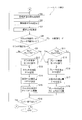
- FIG. 7A is a flow chart for explaining the setting of the initial control mode.
- FIG. 7B is a flow chart for explaining feedback control. The following turning control starts from the state in which the vehicle is traveling straight.
- step S1 the control unit 30 determines whether or not the steering lever 35 is operated in the right turning direction or the left turning direction. If the steering lever 35 is not operated, the process ends. When the steering lever 35 is operated, the process proceeds to step S2.
- step S2 the control unit 30 determines whether or not the amount of operation of the steering lever 35 is equal to or less than a predetermined amount. When the operation amount is not more than a predetermined amount, the process proceeds to step S3, and the control unit 30 sets the control mode of the turning control to the clutch control mode. If the amount of operation is not less than or equal to the predetermined amount, the process proceeds to step S4, and the control unit 30 sets the control mode of turning control to the brake control mode.
- step S5 the control unit 30 sets the target turning radius Ra based on the amount of operation of the steering lever 35.
- step S6 the control unit 30 calculates the actual turning radius Rb of the vehicle based on the output rotation speeds of the left and right steering brakes 13L and 13R acquired from the left and right rotation speed detection sensors 32L and 32R.
- the actual turning radius Rb can be calculated from the following equation (1).
- B is the distance between the central portions of the tracks 3L and 3R in the vehicle width direction in the vehicle width direction
- V1 is the traveling speed of the tracks on the turning direction side
- V2 is opposite to the turning direction. The running speed of the track on the side.
- step S7 the control unit 30 calculates the deviation ⁇ R by subtracting the target turning radius Ra from the actual turning radius Rb.
- step S8 the control unit 30 determines whether the control mode of turning control is the clutch control mode or the brake control mode.
- step S8 When it is determined in step S8 that the control mode of the turning control is the clutch control mode, the process proceeds to step S9, and the control unit 30 determines whether or not the actual turning radius Rb is larger than the target turning radius Ra by the first threshold value TH1 or more. Is determined.
- the first threshold value TH1 is set based on, for example, the ratio of the deviation ⁇ R to the target turning radius Ra.
- the first threshold TH1 is set to a value greater than 0. The smaller the first threshold TH1, the more accurately the transition from the clutch control mode to the brake control mode is performed, and the larger the first threshold TH1, the more hysteresis is given to the transition from the clutch control mode to the brake control mode, resulting in hunting. It is suppressed.
- step S9 When it is determined in step S9 that the actual turning radius Rb is larger than the target turning radius Ra by the first threshold value TH1 or more, the process proceeds to step S10, and the control unit 30 changes the turning control control mode from the clutch control mode to the brake control mode. Migrate to. If it is determined in step S9 that the actual turning radius Rb is not larger than the target turning radius Ra by the first threshold value TH1 or more, the process proceeds to step S13.
- step S8 When it is determined in step S8 that the control mode of the turning control is the brake control mode, the process proceeds to step S11, and the control unit 30 determines whether or not the target turning radius Ra is larger than the actual turning radius Rb by the second threshold value TH2 or more. Is determined.
- the second threshold TH2 is set based on, for example, the ratio of the deviation ⁇ R to the target turning radius Ra.
- the second threshold TH2 is set to a value greater than 0. The smaller the second threshold TH2 is, the more accurately the transition from the brake control mode to the clutch control mode is performed, and the larger the second threshold TH2 is, the more hysteresis is given to the transition from the brake control mode to the clutch control mode, resulting in hunting. It is suppressed.
- step S11 When it is determined in step S11 that the target turning radius Ra is larger than the actual turning radius Rb by the second threshold value TH2 or more, the process proceeds to step S12, and the control unit 30 changes the turning control control mode from the brake control mode to the clutch control mode. Migrate to. If it is determined in step S11 that the target turning radius Ra is not larger than the actual turning radius Rb by the second threshold value TH2 or more, the process proceeds to step S16.
- control unit 30 turns among the left and right steering clutches 12L and 12R based on the amount of operation of the steering lever 35.
- the oil pressure P1 of one of the steering clutches located on the directional side is set.
- step S14 the control unit 30 calculates the correction amount ⁇ P1 of the oil pressure P1 by multiplying the deviation ⁇ R by a predetermined gain.
- the correction amount ⁇ P1 may be determined based on the deviation ⁇ R, and the calculation method of the correction amount ⁇ P1 is not particularly limited.
- step S15 the control unit 30 controls one of the clutch control valves 27L and 27R so that the oil pressure of one steering clutch becomes P1 + ⁇ P1. As a result, the degree of engagement of one steering clutch is controlled so that the deviation ⁇ R becomes small.
- step S11 the control unit 30 turns among the left and right steering brakes 13L and 13R based on the amount of operation of the steering lever 35.
- the oil pressure P2 of one of the steering brakes located on the directional side is set.
- step S17 the control unit 30 calculates the correction amount ⁇ P2 of the oil pressure P2 by multiplying the deviation ⁇ R by a predetermined gain.
- the correction amount ⁇ P2 may be determined based on the deviation ⁇ R, and the calculation method of the correction amount ⁇ P2 is not particularly limited.
- step S18 the control unit 30 controls one of the brake control valves 28L and 28R so that the oil pressure of one steering brake becomes P2 + ⁇ P2. As a result, the degree of engagement of one steering brake is controlled so that the deviation ⁇ R becomes small.
- step S15 or step S18 the process proceeds to step S19, and the control unit 30 determines whether or not the steering lever 35 is operated in the right turning direction or the left turning direction. If the steering lever 35 is not operated, the process ends. When the steering lever 35 is operated, the control unit 30 returns the process to step S5 and repeats the above-described control mode switching and engagement degree control.
- the bulldozer 1 includes a control unit 30 that executes vehicle turning control in a clutch control mode or a brake control mode by controlling the left and right steering clutches 12L and 12R and the left and right steering brakes 13L and 13R. ..
- the control unit 30 switches between the clutch control mode and the brake control mode based on the deviation ⁇ R between the actual turning radius Rb and the target turning radius Ra.
- FIGS. 8A to 8D are diagrams for explaining how the control mode of turning control shifts from the clutch control mode to the brake control mode.
- FIG. 8A is a graph showing the amount of operation of the steering lever 35.
- FIG. 8B is a graph showing the oil pressures of the steering clutch and the steering brake located on the turning direction side.
- FIG. 8C is a graph showing the time course of the deviation ⁇ R.
- FIG. 8D is a graph showing changes over time in the target turning radius Ra and the actual turning radius Rb.
- the bulldozer 1 when the operation amount of the steering lever 35 gradually increases from the time t0 to the time t2, as shown in FIGS.
- the control mode of turning control automatically shifts from the clutch control mode to the brake control mode. Therefore, as shown in FIG. 8D, the actual turning radius Rb can be easily and smoothly approximated to the target turning radius Ra.
- the bulldozer 1 is provided with the steering lever 35, but when the bulldozer 1 is operated unmanned remotely, the bulldozer 1 does not have to be provided with the steering lever 35.
- the information indicating the target turning radius Ra may be directly input to the control unit 30.
- control unit 30 calculates the actual turning radius Rb based on the output rotation speeds of the left and right steering brakes 13L and 13R, but the present invention is not limited to this.
- the control unit 30 may calculate the actual turning radius Rb using an IMU (inertial measurement unit), GPS (Global Positioning System), acceleration sensor, gyro sensor, yaw rate sensor, azimuth sensor, or the like.
- IMU intial measurement unit
- GPS Global Positioning System
- acceleration sensor gyro sensor
- yaw rate sensor yaw rate sensor
- azimuth sensor azimuth sensor
- the control unit 30 switches between the clutch control mode and the brake control mode by using the deviation ⁇ R between the actual turning radius Rb and the target turning radius Ra, but the present invention is not limited to this.
- the control mode may be switched using the deviation ⁇ between the actual direction and the target direction defined in the global coordinate system.
- the actual direction can be obtained from the GNSS radio wave.
- the left and right steering clutches 12L and 12R are arranged between the power transmission device 11 and the left and right sprockets 2L and 2R, and the left and right steering brakes 13L and 13R are left and right steering clutches 12L and 12R. It was decided to place it between the sprockets 2L and 2R, but it is not limited to this.
- the left and right steering clutches 12L and 12R may be capable of transmitting or blocking power from the power transmission device 11 to the left and right sprockets 2L and 2R, and the left and right steering brakes 13L and 13R rotate the left and right sprockets 2L and 2R. It suffices if braking is possible.
- left and right planetary gear mechanisms 40L and 40R are arranged between the power transmission device 11 and the left and right sprockets 2L and 2R, and the left and right planetary gear mechanisms 40L and 40R and the left and right sprockets 2L,
- the left and right steering brakes 13L and 13R may be arranged between the 2R and the left and right steering brakes 13L and 13R.
- the left and right planetary gear mechanisms 40L and 40R have left and right ring gears 41L and 41R, left and right planetary gears 42L and 42R, left and right sun gears 43L and 43R, and left and right carriers 44L and 44R.
- the left and right steering clutches 12L and 12R can be engaged with or released from the left and right sun gears 43L and 43R.
- the left steering clutch 12L When the left steering clutch 12L is engaged with the left sun gear 43L and the left sun gear 43L is in the braking state, the rotation of the horizontal shaft 20 is transferred to the left output shaft 21L via the left ring gear 41L, the left planetary gear 42L and the left carrier 44L. Be transmitted.
- the left steering clutch 12L is released from the left sun gear 43L and the left sun gear 43L is in a free rotation state, the rotation of the horizontal shaft 20 is not transmitted to the left output shaft 21L. In this way, the left steering clutch 12L can transmit or cut off the power from the power transmission device 11 to the left sprocket 2L.
- the right steering clutch 12R can also transmit or cut off the power from the power transmission device 11 to the right sprocket 2R.
- the left steering clutch 12L is connected to the motor 52 via the idler gear 50 and the pinion gear 51
- the right steering clutch 12R is the first transfer gear 53, the auxiliary shaft 54, and the second transfer gear. It is connected to the motor 52 via 55, an idler gear 50 and a pinion gear 51.
- the left and right steering clutches 12L and 12R are engaged, the rotational power of the motor 52 is transmitted to the left and right sun gears 43L and 43R via the left and right steering clutches 12L and 12R, and the left and right sun gears 43L and 43R communicate with each other.
- the work machine can make a slow turn or a true turn.
- the motor 52 is an arbitrary component. When the motor 52 is not installed, at least one of the idler gear 50 and the pinion gear 51 may be fixed.
Abstract
A bulldozer (1) is provided with a control unit (30) that caries out vehicle turn control by way of controlling left and right steering clutches (12L, 12R) and left and right steering brakes (13L, 13R). The control unit (30) switches between clutch control and brake control on the basis of the deviation (ΔR) between the actual turning radius (Rb) and a target turning radius (Ra).
Description
本開示は、履帯式作業機械に関する。
This disclosure relates to track-type work machines.
履帯式作業機械(例えば、ブルドーザなど)においては、エンジンの動力がトランスミッションを介して左右の駆動輪に伝達され、左右の駆動輪によって左右の履帯が駆動される。
In a track-type work machine (for example, a bulldozer), engine power is transmitted to the left and right drive wheels via a transmission, and the left and right drive wheels drive the left and right tracks.
このような履帯式作業機械では、左右の駆動輪に対応して設けられた左右のステアリングクラッチ及びステアリングブレーキを油圧制御することによって、左右の旋回が実行される。
In such a track-type work machine, left and right turning is executed by hydraulically controlling the left and right steering clutches and steering brakes provided corresponding to the left and right drive wheels.
例えば、走行中に左緩旋回する場合は、左ステアリングクラッチを部分係合させるとともに、左ステアリングブレーキを開放させる。また、走行中に左急旋回する場合は、左ステアリングクラッチを開放させるとともに、左ステアリングブレーキを完全係合又は部分係合させる。
For example, when turning slowly to the left while driving, the left steering clutch is partially engaged and the left steering brake is released. When making a sharp left turn while driving, the left steering clutch is released and the left steering brake is fully or partially engaged.
特許文献1では、実旋回角速度と目標旋回角速度との偏差に基づいてステアリングクラッチ及びステアリングブレーキを油圧制御することによって、実旋回半径を目標旋回半径に近似させる手法が提案されている。しかしながら、特許文献1に記載の手法では、操向レバーの操作量に応じて設定された目標旋回角速度の値に基づいてステアリングクラッチ及びステアリングブレーキのいずれを開放するかが決められる。そのため、傾斜地走行中やドージング作業中には実旋回半径を目標旋回半径に近似させることが困難な場合がある。
Patent Document 1 proposes a method of approximating the actual turning radius to the target turning radius by hydraulically controlling the steering clutch and the steering brake based on the deviation between the actual turning angular velocity and the target turning angular velocity. However, in the method described in Patent Document 1, it is determined whether to release the steering clutch or the steering brake based on the value of the target turning angular velocity set according to the operating amount of the steering lever. Therefore, it may be difficult to approximate the actual turning radius to the target turning radius while traveling on a slope or during dosing work.
そこで、特許文献2では、傾斜地走行中やドージング作業中などの走行状態に応じて、ステアリングクラッチ及びステアリングブレーキのモジュレーション特性を選択する手法が提案されている。
Therefore, Patent Document 2 proposes a method of selecting the modulation characteristics of the steering clutch and the steering brake according to the traveling state such as traveling on a slope or during dosing work.
しかしながら、特許文献2の手法では、あらゆる走行状態に適したモジュレーション特性を選択するには、多数のモジュレーション特性を準備する必要があるだけでなく、走行状態を正確に判定するために膨大な入力パラメータを取得する必要もある。
However, in the method of Patent Document 2, not only a large number of modulation characteristics need to be prepared in order to select a modulation characteristic suitable for all running conditions, but also a huge number of input parameters are required to accurately determine the running condition. You also need to get.
本開示の課題は、簡便に実旋回半径を目標旋回半径に近似させることのできる履帯式作業機械を提供することにある。
An object of the present disclosure is to provide a track-type work machine capable of easily approximating the actual turning radius to the target turning radius.
本開示の一側面に係る履帯式作業機械は、エンジンと、左右の駆動輪と、動力伝達装置と、左右のステアリングクラッチと、左右のステアリングブレーキと、制御部とを備える。左右の駆動輪は、左右の履帯を駆動させる。動力伝達装置は、エンジンからの動力を伝達する。左右のステアリングクラッチは、動力伝達装置から左右の駆動輪それぞれへの動力を伝達又は遮断する。左右のステアリングブレーキは、左右の駆動輪の回転を制動する。制御部は、左右のステアリングクラッチ及び左右のステアリングブレーキを制御することによって車両の旋回制御を実行する。制御部は、実旋回半径と目標旋回半径との偏差又は実方位と目標方位との偏差に基づいて、クラッチ制御とブレーキ制御とを切り替える。
The track-type work machine according to one aspect of the present disclosure includes an engine, left and right drive wheels, a power transmission device, left and right steering clutches, left and right steering brakes, and a control unit. The left and right drive wheels drive the left and right tracks. The power transmission device transmits power from the engine. The left and right steering clutches transmit or cut off power from the power transmission device to each of the left and right drive wheels. The left and right steering brakes brake the rotation of the left and right drive wheels. The control unit executes turning control of the vehicle by controlling the left and right steering clutches and the left and right steering brakes. The control unit switches between clutch control and brake control based on the deviation between the actual turning radius and the target turning radius or the deviation between the actual direction and the target direction.
本開示に係る履帯式作業機械によれば、簡便に実旋回半径を目標旋回半径に近似させることができる。
According to the track-type work machine according to the present disclosure, the actual turning radius can be easily approximated to the target turning radius.
[ブルドーザ1の構成]
図1は、履帯式作業機械の一例であるブルドーザ1の斜視図である。 [Structure of bulldozer 1]
FIG. 1 is a perspective view of abulldozer 1 which is an example of a track-type work machine.
図1は、履帯式作業機械の一例であるブルドーザ1の斜視図である。 [Structure of bulldozer 1]
FIG. 1 is a perspective view of a
ブルドーザ1は、左右のスプロケット2L,2R(左右の駆動輪の一例)及び左右の履帯3L,3Rを有する左右の走行装置4L,4Rと、車両前部に設けられたブレード5と、車両後部に設けられたリッパ装置6とを備える。
The bulldozer 1 includes left and right traveling devices 4L and 4R having left and right sprockets 2L and 2R (an example of left and right driving wheels) and left and right tracks 3L and 3R, blades 5 provided at the front of the vehicle, and rear of the vehicle. It is provided with a ripper device 6 provided.
このブルドーザ1は、ブレード5による土押し等の作業、リッパ装置6による破砕及び掘削等の作業を行うことができる。
This bulldozer 1 can perform work such as soil pushing by the blade 5 and work such as crushing and excavation by the ripper device 6.
[動力伝達系統の構成]
図2は、ブルドーザ1の動力伝達系統の構成を示す模式図である。図3は、ブルドーザ1の動力伝達系統の概略システム構成図である。ただし、図3では、エンジン10、ダンパ15及びトルクコンバータ16が省略されている。 [Structure of power transmission system]
FIG. 2 is a schematic diagram showing the configuration of the power transmission system of thebulldozer 1. FIG. 3 is a schematic system configuration diagram of the power transmission system of the bulldozer 1. However, in FIG. 3, the engine 10, the damper 15, and the torque converter 16 are omitted.
図2は、ブルドーザ1の動力伝達系統の構成を示す模式図である。図3は、ブルドーザ1の動力伝達系統の概略システム構成図である。ただし、図3では、エンジン10、ダンパ15及びトルクコンバータ16が省略されている。 [Structure of power transmission system]
FIG. 2 is a schematic diagram showing the configuration of the power transmission system of the
ブルドーザ1は、エンジン10と、動力伝達装置11と、左右のステアリングクラッチ12L,12Rと、左右のステアリングブレーキ13L,13Rと、制御部30とを有する。
The bulldozer 1 has an engine 10, a power transmission device 11, left and right steering clutches 12L and 12R, left and right steering brakes 13L and 13R, and a control unit 30.
動力伝達装置11は、エンジン10からの動力を伝達する。動力伝達装置11は、ダンパ15、トルクコンバータ16、トランスミッション17、ピニオン18、ベベルギア19及び横軸20を含む。動力伝達装置11では、エンジン10からの動力は、ダンパ15を介してトルクコンバータ16に伝達される。トルクコンバータ16の出力軸は、トランスミッション17の入力軸に連結されており、トルクコンバータ16からトランスミッション17に動力が伝達される。トランスミッション17から出力された動力は、ピニオン18及びベベルギア19を介して、横軸20に伝達される。
The power transmission device 11 transmits the power from the engine 10. The power transmission device 11 includes a damper 15, a torque converter 16, a transmission 17, a pinion 18, a bevel gear 19, and a horizontal shaft 20. In the power transmission device 11, the power from the engine 10 is transmitted to the torque converter 16 via the damper 15. The output shaft of the torque converter 16 is connected to the input shaft of the transmission 17, and power is transmitted from the torque converter 16 to the transmission 17. The power output from the transmission 17 is transmitted to the horizontal axis 20 via the pinion 18 and the bevel gear 19.
横軸20に伝達された動力は、左ステアリングクラッチ12L、左出力軸21L及び左終減速装置22Lを介して左スプロケット2Lに伝達されるとともに、右ステアリングクラッチ12R、右出力軸21R及び右終減速装置22Rを介して右スプロケット2Rに伝達される。
The power transmitted to the horizontal shaft 20 is transmitted to the left sprocket 2L via the left steering clutch 12L, the left output shaft 21L and the left final deceleration device 22L, and is also transmitted to the right steering clutch 12R, the right output shaft 21R and the right final deceleration. It is transmitted to the right sprocket 2R via the device 22R.
各スプロケット2L,2Rには履帯3L,3Rが巻回されている。スプロケットが回転駆動されると、履帯3L,3Rが駆動され、これによりブルドーザ1が走行する。
Tracks 3L and 3R are wound around each sprocket 2L and 2R. When the sprocket is rotationally driven, the tracks 3L and 3R are driven, which causes the bulldozer 1 to travel.
左右のステアリングクラッチ12L,12Rは、動力伝達装置11から左右のスプロケット2L,2Rへの動力を伝達又は遮断する。左右のステアリングクラッチ12L,12Rそれぞれは、油圧によって係合状態(すなわち、動力伝達状態)と開放状態(すなわち、動力遮断状態)とに切替可能な油圧クラッチである。左右のステアリングクラッチ12L,12Rの係合には、完全係合と部分係合とが含まれる。左ステアリングクラッチ12Lが係合されると、ベベルギア19からの動力が左スプロケット2Lに伝達される。右ステアリングクラッチ12Rが係合されると、ベベルギア19からの動力が右スプロケット2Rに伝達される。
The left and right steering clutches 12L and 12R transmit or cut off the power from the power transmission device 11 to the left and right sprockets 2L and 2R. Each of the left and right steering clutches 12L and 12R is a hydraulic clutch that can be switched between an engaged state (that is, a power transmission state) and an open state (that is, a power cutoff state) by hydraulic pressure. The engagement of the left and right steering clutches 12L and 12R includes full engagement and partial engagement. When the left steering clutch 12L is engaged, the power from the bevel gear 19 is transmitted to the left sprocket 2L. When the right steering clutch 12R is engaged, the power from the bevel gear 19 is transmitted to the right sprocket 2R.
左右のステアリングクラッチ12L,12Rへの圧油の供給及び排出は、クラッチ用コントロールバルブ27L,27Rによって制御される。左右のステアリングクラッチ12L,12Rは、ネガティブタイプの油圧クラッチであり、油圧が供給されていないとき完全係合され、供給される油圧が所定値より低いとき部分係合され、供給される油圧が所定値以上であるとき開放される。
The supply and discharge of pressure oil to the left and right steering clutches 12L and 12R are controlled by the clutch control valves 27L and 27R. The left and right steering clutches 12L and 12R are negative type hydraulic clutches, which are fully engaged when no hydraulic pressure is supplied, partially engaged when the supplied hydraulic pressure is lower than a predetermined value, and the supplied hydraulic pressure is predetermined. It is released when it is above the value.
本実施形態において、左右のステアリングクラッチ12L,12Rは、動力伝達装置11と左右のスプロケット2L,2Rとの間に配置される。
In the present embodiment, the left and right steering clutches 12L and 12R are arranged between the power transmission device 11 and the left and right sprockets 2L and 2R.
左右のステアリングブレーキ13L,13Rは、左右のスプロケット2L,2Rの回転を制動する。左右のステアリングブレーキ13L,13Rは、油圧によって係合状態(すなわち、制動状態)と開放状態(すなわち、非制動状態)とに切替可能な油圧式のブレーキである。左右のステアリングブレーキ13L,13Rの係合には、完全係合と部分係合とが含まれる。左ステアリングブレーキ13Lが係合されると、左ステアリングクラッチ12Lの出力回転、すなわち左スプロケット2Lの回転が制動される。右ステアリングブレーキ13Rが係合されると、右ステアリングクラッチ12Rの出力回転、すなわち右スプロケット2Rの回転が制動される。
The left and right steering brakes 13L and 13R brake the rotation of the left and right sprockets 2L and 2R. The left and right steering brakes 13L and 13R are hydraulic brakes that can be switched between an engaged state (that is, a braking state) and an open state (that is, a non-braking state) by flood control. The engagement of the left and right steering brakes 13L and 13R includes a complete engagement and a partial engagement. When the left steering brake 13L is engaged, the output rotation of the left steering clutch 12L, that is, the rotation of the left sprocket 2L is braked. When the right steering brake 13R is engaged, the output rotation of the right steering clutch 12R, that is, the rotation of the right sprocket 2R is braked.
左右のステアリングブレーキ13L,13Rへの圧油の供給及び排出は、ブレーキ用コントロールバルブ28L,28Rによって制御される。左右のステアリングブレーキ13L,13Rは、常時制動タイプの油圧ブレーキであり、油圧が供給されていないとき完全係合され、供給される油圧が所定値より低いとき部分係合され、供給される油圧が所定値以上であるとき開放される。
The supply and discharge of pressure oil to the left and right steering brakes 13L and 13R are controlled by the brake control valves 28L and 28R. The left and right steering brakes 13L and 13R are constant braking type hydraulic brakes, which are fully engaged when no hydraulic pressure is supplied, and partially engaged when the supplied hydraulic pressure is lower than a predetermined value, and the supplied hydraulic pressure is It is released when it is equal to or more than a predetermined value.
本実施形態において、左右のステアリングブレーキ13L,13Rは、左右のステアリングクラッチ12L,12Rと左右のスプロケット2L,2Rとの間に配置される。
In the present embodiment, the left and right steering brakes 13L and 13R are arranged between the left and right steering clutches 12L and 12R and the left and right sprockets 2L and 2R.
左右のステアリングブレーキ13L,13Rの出力側には、左右の回転数検出センサ32L,32Rが設けられる。左右の回転数検出センサ32L,32Rは、左右のステアリングブレーキ13L,13Rの出力回転数を検出する。左右の回転数検出センサ32L,32Rは、検出した出力回転数を制御部30に送信する。
Left and right rotation speed detection sensors 32L and 32R are provided on the output side of the left and right steering brakes 13L and 13R. The left and right rotation speed detection sensors 32L and 32R detect the output rotation speeds of the left and right steering brakes 13L and 13R. The left and right rotation speed detection sensors 32L and 32R transmit the detected output rotation speed to the control unit 30.
制御部30は、オペレータによる操向操作に用いられる操向レバー35から操向指令を取得する。制御部30は、オペレータによる操向レバー35の操作に応じて、車両の旋回制御を実行する。具体的には、制御部30は、操向レバー35が操作されると、操向レバー35の操作方向に応じて旋回方向(右方向又は左方向)を設定するとともに、操向レバー35の操作量に応じて目標旋回半径Raを設定する。制御部30は、設定された旋回方向に向かって設定された目標旋回半径Raで車両が旋回するように、クラッチ用コントロールバルブ27L,27R及びブレーキ用コントロールバルブ28L,28Rを介して左右のステアリングクラッチ12L,12R及び左右のステアリングブレーキ13L,13Rを制御する。
The control unit 30 acquires a steering command from the steering lever 35 used for steering operation by the operator. The control unit 30 executes the turning control of the vehicle in response to the operation of the steering lever 35 by the operator. Specifically, when the steering lever 35 is operated, the control unit 30 sets the turning direction (right direction or left direction) according to the operating direction of the steering lever 35, and operates the steering lever 35. The target turning radius Ra is set according to the amount. The control unit 30 uses the left and right steering clutches via the clutch control valves 27L and 27R and the brake control valves 28L and 28R so that the vehicle turns with the target turning radius Ra set in the set turning direction. It controls 12L, 12R and the left and right steering brakes 13L, 13R.
制御部30は、旋回制御の実行中、左右の回転数検出センサ32L,32Rから取得する左右のステアリングブレーキ13L,13Rの出力回転数に基づいて、車両の実旋回半径Rbを算出する。そして、制御部30は、実旋回半径Rbと目標旋回半径Raとの偏差ΔRに基づいて、左右のステアリングクラッチ12L,12Rいずれかの制御(以下、「クラッチ制御」という。)による旋回と、左右のステアリングブレーキ13L,13Rの制御(以下、「ブレーキ制御」という。)による旋回とを自動的に切り替える。
The control unit 30 calculates the actual turning radius Rb of the vehicle based on the output rotation speeds of the left and right steering brakes 13L and 13R acquired from the left and right rotation speed detection sensors 32L and 32R while the turning control is being executed. Then, the control unit 30 turns by controlling either the left or right steering clutch 12L or 12R (hereinafter, referred to as "clutch control") based on the deviation ΔR between the actual turning radius Rb and the target turning radius Ra, and left and right. Automatically switches between turning by controlling the steering brakes 13L and 13R (hereinafter referred to as "brake control").
本明細書において、クラッチ制御によって旋回することを「クラッチ制御モード」と略称する。クラッチ制御モードでは、左右のステアリングクラッチ12L,12Rのうち旋回方向側に位置する一方のステアリングクラッチを部分係合させ、かつ、左右のステアリングブレーキ13L,13Rのうち旋回方向側に位置する一方のステアリングブレーキを開放させる。また、クラッチ制御モードでは、左右のステアリングクラッチ12L,12Rのうち旋回方向の反対側に位置する他方のステアリングクラッチを完全係合させ、かつ、左右のステアリングブレーキ13L,13Rのうち旋回方向の反対側に位置する他方のステアリングブレーキを開放させる。クラッチ制御モードでは、一方のステアリングクラッチの係合度合いを制御することによって実旋回半径Rbの調整が行われる。クラッチ制御モードは、主として、実旋回半径Rbが目標旋回半径Raより小さい場合に用いられる。
In this specification, turning by clutch control is abbreviated as "clutch control mode". In the clutch control mode, one of the left and right steering clutches 12L and 12R located on the turning direction side is partially engaged, and one of the left and right steering brakes 13L and 13R located on the turning direction side is steered. Release the brake. Further, in the clutch control mode, the other steering clutch located on the opposite side of the left and right steering clutches 12L and 12R in the turning direction is completely engaged, and the opposite side of the left and right steering brakes 13L and 13R in the turning direction. Release the other steering brake located at. In the clutch control mode, the actual turning radius Rb is adjusted by controlling the degree of engagement of one steering clutch. The clutch control mode is mainly used when the actual turning radius Rb is smaller than the target turning radius Ra.
本明細書において、ブレーキ制御によって旋回することを「ブレーキ制御モード」と略称する。ブレーキ制御モードとは、左右のステアリングクラッチ12L,12Rのうち旋回方向側に位置する一方のステアリングクラッチを開放させ、かつ、左右のステアリングブレーキ13L,13Rのうち旋回方向側に位置する一方のステアリングブレーキを完全係合又は部分係合させた状態を意味する。ブレーキ制御モードでは、一方のステアリングブレーキの係合度合いを制御することによって実旋回半径Rbの調整が行われる。ブレーキ制御モードは、主として、実旋回半径Rbが目標旋回半径Raより大きい場合に用いられる。
In this specification, turning by brake control is abbreviated as "brake control mode". The brake control mode is a steering brake that releases one of the left and right steering clutches 12L and 12R located on the turning direction side and one of the left and right steering brakes 13L and 13R located on the turning direction side. Means a state in which the above is fully engaged or partially engaged. In the brake control mode, the actual turning radius Rb is adjusted by controlling the degree of engagement of one of the steering brakes. The brake control mode is mainly used when the actual turning radius Rb is larger than the target turning radius Ra.
そして、制御部30は、図4に示すように、クラッチ制御モードとブレーキ制御モードとを自動的に切り替えて旋回制御を実行しながら、実旋回半径Rbと目標旋回半径Raとの偏差ΔRに基づいて、実旋回半径Rbが目標旋回半径Raに近づくように一方のステアリングクラッチ又は一方のステアリングブレーキの油圧を調整する。
Then, as shown in FIG. 4, the control unit 30 automatically switches between the clutch control mode and the brake control mode to execute turning control, and is based on the deviation ΔR between the actual turning radius Rb and the target turning radius Ra. Then, the oil pressure of one steering clutch or one steering brake is adjusted so that the actual turning radius Rb approaches the target turning radius Ra.
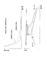
具体的には、図5に示すように、登坂中あるいはドージング中などのような高負荷状態では、実旋回半径Rbが目標旋回半径Raより小さくなりやすい。この場合、制御部30は、操向レバー35の操作量によって決定されるクラッチ制御モードからブレーキ制御モードへの切り替えタイミングよりも遅いタイミングで、クラッチ制御モードからブレーキ制御モードに切り替えることによって、精度良く実旋回半径Rbを目標旋回半径Raに近づけることができる。この際、操向レバー35の操作量に対するクラッチ圧の傾きは小さくなり、操向レバー35の操作量に対するブレーキ圧の傾きは大きくなる。
Specifically, as shown in FIG. 5, the actual turning radius Rb tends to be smaller than the target turning radius Ra in a high load state such as during climbing or dosing. In this case, the control unit 30 accurately switches from the clutch control mode to the brake control mode at a timing later than the switching timing from the clutch control mode to the brake control mode determined by the operation amount of the steering lever 35. The actual turning radius Rb can be brought closer to the target turning radius Ra. At this time, the inclination of the clutch pressure with respect to the operating amount of the steering lever 35 becomes small, and the inclination of the brake pressure with respect to the operating amount of the steering lever 35 becomes large.
また、図6に示すように、降坂中あるいは無負荷自走中などのような低負荷状態では、実旋回半径Rbが目標旋回半径Raより大きくなりやすい。この場合、制御部30は、操向レバー35の操作量によって決定されるクラッチ制御モードからブレーキ制御モードへの切り替えタイミングよりも早いタイミングで、クラッチ制御モードからブレーキ制御モードに切り替えることによって、精度良く実旋回半径Rbが目標旋回半径Raに近づけることができる。この際、操向レバー35の操作量に対するクラッチ圧の傾きは大きくなり、操向レバー35の操作量に対するブレーキ圧の傾きは小さくなる。
Further, as shown in FIG. 6, the actual turning radius Rb tends to be larger than the target turning radius Ra in a low load state such as when descending a slope or when the vehicle is self-propelled with no load. In this case, the control unit 30 accurately switches from the clutch control mode to the brake control mode at a timing earlier than the switching timing from the clutch control mode to the brake control mode, which is determined by the operation amount of the steering lever 35. The actual turning radius Rb can be brought closer to the target turning radius Ra. At this time, the inclination of the clutch pressure with respect to the operating amount of the steering lever 35 becomes large, and the inclination of the brake pressure with respect to the operating amount of the steering lever 35 becomes small.
[旋回制御]
次に、制御部30による旋回制御について、図面を参照しながら説明する。図7Aは、初期の制御モードの設定について説明するためのフロー図である。図7Bは、フィードバック制御について説明するためのフロー図である。以下の旋回制御は、車両が直進走行中の状態から開始する。 [Turning control]
Next, the turning control by thecontrol unit 30 will be described with reference to the drawings. FIG. 7A is a flow chart for explaining the setting of the initial control mode. FIG. 7B is a flow chart for explaining feedback control. The following turning control starts from the state in which the vehicle is traveling straight.
次に、制御部30による旋回制御について、図面を参照しながら説明する。図7Aは、初期の制御モードの設定について説明するためのフロー図である。図7Bは、フィードバック制御について説明するためのフロー図である。以下の旋回制御は、車両が直進走行中の状態から開始する。 [Turning control]
Next, the turning control by the
ステップS1において、制御部30は、操向レバー35が右旋回方向又は左旋回方向に操作されているか否かを判定する。操向レバー35が操作されていない場合、処理は終了する。操向レバー35が操作されている場合、処理はステップS2に進む。
In step S1, the control unit 30 determines whether or not the steering lever 35 is operated in the right turning direction or the left turning direction. If the steering lever 35 is not operated, the process ends. When the steering lever 35 is operated, the process proceeds to step S2.
ステップS2において、制御部30は、操向レバー35の操作量が所定量以下であるか否かを判定する。操作量が所定量以下である場合、処理はステップS3に進み、制御部30は、旋回制御の制御モードをクラッチ制御モードに設定する。操作量が所定量以下でない場合、処理はステップS4に進み、制御部30は、旋回制御の制御モードをブレーキ制御モードに設定する。
In step S2, the control unit 30 determines whether or not the amount of operation of the steering lever 35 is equal to or less than a predetermined amount. When the operation amount is not more than a predetermined amount, the process proceeds to step S3, and the control unit 30 sets the control mode of the turning control to the clutch control mode. If the amount of operation is not less than or equal to the predetermined amount, the process proceeds to step S4, and the control unit 30 sets the control mode of turning control to the brake control mode.
ステップS5において、制御部30は、操向レバー35の操作量に基づいて、目標旋回半径Raを設定する。
In step S5, the control unit 30 sets the target turning radius Ra based on the amount of operation of the steering lever 35.
ステップS6において、制御部30は、左右の回転数検出センサ32L,32Rから取得する左右のステアリングブレーキ13L,13Rの出力回転数に基づいて、車両の実旋回半径Rbを算出する。実旋回半径Rbは、下記式(1)から算出することができる。
 In step S6, the
 control unit 30 calculates the actual turning radius Rb of the vehicle based on the output rotation speeds of the left and right steering brakes 13L and 13R acquired from the left and right rotation speed detection sensors 32L and 32R. The actual turning radius Rb can be calculated from the following equation (1).
式(1)において、Bは、車幅方向における各履帯3L,3Rの車幅方向中央部の間隔であり、V1は、旋回方向側の履帯の走行速度であり、V2は、旋回方向と反対側の履帯の走行速度である。
In the formula (1), B is the distance between the central portions of the tracks 3L and 3R in the vehicle width direction in the vehicle width direction, V1 is the traveling speed of the tracks on the turning direction side, and V2 is opposite to the turning direction. The running speed of the track on the side.
ステップS7において、制御部30は、実旋回半径Rbから目標旋回半径Raを引くことによって偏差ΔRを算出する。
In step S7, the control unit 30 calculates the deviation ΔR by subtracting the target turning radius Ra from the actual turning radius Rb.
ステップS8において、制御部30は、旋回制御の制御モードがクラッチ制御モードであるかブレーキ制御モードであるかを判定する。
In step S8, the control unit 30 determines whether the control mode of turning control is the clutch control mode or the brake control mode.
ステップS8において旋回制御の制御モードがクラッチ制御モードであると判定された場合、処理はステップS9に進み、制御部30は、実旋回半径Rbが目標旋回半径Raより第1閾値TH1以上大きいか否かを判定する。第1閾値TH1は、例えば目標旋回半径Raに対する偏差ΔRの比に基づいて設定される。第1閾値TH1は、0より大きい値に設定される。第1閾値TH1を小さくするほどクラッチ制御モードからブレーキ制御モードへの移行が精度良く行われ、第1閾値TH1を大きくするほどクラッチ制御モードからブレーキ制御モードへの移行にヒステリシスが付与されてハンチングが抑制される。
When it is determined in step S8 that the control mode of the turning control is the clutch control mode, the process proceeds to step S9, and the control unit 30 determines whether or not the actual turning radius Rb is larger than the target turning radius Ra by the first threshold value TH1 or more. Is determined. The first threshold value TH1 is set based on, for example, the ratio of the deviation ΔR to the target turning radius Ra. The first threshold TH1 is set to a value greater than 0. The smaller the first threshold TH1, the more accurately the transition from the clutch control mode to the brake control mode is performed, and the larger the first threshold TH1, the more hysteresis is given to the transition from the clutch control mode to the brake control mode, resulting in hunting. It is suppressed.
ステップS9において実旋回半径Rbが目標旋回半径Raより第1閾値TH1以上大きいと判定された場合、処理はステップS10に進み、制御部30は、旋回制御の制御モードをクラッチ制御モードからブレーキ制御モードに移行させる。ステップS9において実旋回半径Rbが目標旋回半径Raより第1閾値TH1以上大きくないと判定された場合、処理はステップS13に進む。
When it is determined in step S9 that the actual turning radius Rb is larger than the target turning radius Ra by the first threshold value TH1 or more, the process proceeds to step S10, and the control unit 30 changes the turning control control mode from the clutch control mode to the brake control mode. Migrate to. If it is determined in step S9 that the actual turning radius Rb is not larger than the target turning radius Ra by the first threshold value TH1 or more, the process proceeds to step S13.
ステップS8において旋回制御の制御モードがブレーキ制御モードであると判定された場合、処理はステップS11に進み、制御部30は、目標旋回半径Raが実旋回半径Rbより第2閾値TH2以上大きいか否かを判定する。第2閾値TH2は、例えば目標旋回半径Raに対する偏差ΔRの比に基づいて設定される。第2閾値TH2は、0より大きい値に設定される。第2閾値TH2を小さくするほどブレーキ制御モードからクラッチ制御モードへの移行が精度良く行われ、第2閾値TH2を大きくするほどブレーキ制御モードからクラッチ制御モードへの移行にヒステリシスが付与されてハンチングが抑制される。
When it is determined in step S8 that the control mode of the turning control is the brake control mode, the process proceeds to step S11, and the control unit 30 determines whether or not the target turning radius Ra is larger than the actual turning radius Rb by the second threshold value TH2 or more. Is determined. The second threshold TH2 is set based on, for example, the ratio of the deviation ΔR to the target turning radius Ra. The second threshold TH2 is set to a value greater than 0. The smaller the second threshold TH2 is, the more accurately the transition from the brake control mode to the clutch control mode is performed, and the larger the second threshold TH2 is, the more hysteresis is given to the transition from the brake control mode to the clutch control mode, resulting in hunting. It is suppressed.
ステップS11において目標旋回半径Raが実旋回半径Rbより第2閾値TH2以上大きいと判定された場合、処理はステップS12に進み、制御部30は、旋回制御の制御モードをブレーキ制御モードからクラッチ制御モードに移行させる。ステップS11において目標旋回半径Raが実旋回半径Rbより第2閾値TH2以上大きくないと判定された場合、処理はステップS16に進む。
When it is determined in step S11 that the target turning radius Ra is larger than the actual turning radius Rb by the second threshold value TH2 or more, the process proceeds to step S12, and the control unit 30 changes the turning control control mode from the brake control mode to the clutch control mode. Migrate to. If it is determined in step S11 that the target turning radius Ra is not larger than the actual turning radius Rb by the second threshold value TH2 or more, the process proceeds to step S16.
ステップS9からステップS13に進んだ場合、又は、ステップS12からステップS13に処理が進んだ場合、制御部30は、操向レバー35の操作量に基づいて、左右のステアリングクラッチ12L,12Rのうち旋回方向側に位置する一方のステアリングクラッチの油圧P1を設定する。
When the process proceeds from step S9 to step S13, or when the process proceeds from step S12 to step S13, the control unit 30 turns among the left and right steering clutches 12L and 12R based on the amount of operation of the steering lever 35. The oil pressure P1 of one of the steering clutches located on the directional side is set.
ステップS14において、制御部30は、偏差ΔRに所定のゲインを乗算することによって、油圧P1の補正量ΔP1を算出する。ただし、補正量ΔP1は偏差ΔRに基づいて決定されればよく、補正量ΔP1の算出方法は特に限られない。
In step S14, the control unit 30 calculates the correction amount ΔP1 of the oil pressure P1 by multiplying the deviation ΔR by a predetermined gain. However, the correction amount ΔP1 may be determined based on the deviation ΔR, and the calculation method of the correction amount ΔP1 is not particularly limited.
ステップS15において、制御部30は、一方のステアリングクラッチの油圧がP1+ΔP1になるようクラッチ用コントロールバルブ27L,27Rの一方を制御する。これにより、偏差ΔRが小さくなるように、一方のステアリングクラッチの係合度合いが制御される。
In step S15, the control unit 30 controls one of the clutch control valves 27L and 27R so that the oil pressure of one steering clutch becomes P1 + ΔP1. As a result, the degree of engagement of one steering clutch is controlled so that the deviation ΔR becomes small.
ステップS11からステップS16に進んだ場合、又は、ステップS10からステップS16に処理が進んだ場合、制御部30は、操向レバー35の操作量に基づいて、左右のステアリングブレーキ13L,13Rのうち旋回方向側に位置する一方のステアリングブレーキの油圧P2を設定する。
When the process proceeds from step S11 to step S16, or when the process proceeds from step S10 to step S16, the control unit 30 turns among the left and right steering brakes 13L and 13R based on the amount of operation of the steering lever 35. The oil pressure P2 of one of the steering brakes located on the directional side is set.
ステップS17において、制御部30は、偏差ΔRに所定のゲインを乗算することによって、油圧P2の補正量ΔP2を算出する。ただし、補正量ΔP2は偏差ΔRに基づいて決定されればよく、補正量ΔP2の算出方法は特に限られない。
In step S17, the control unit 30 calculates the correction amount ΔP2 of the oil pressure P2 by multiplying the deviation ΔR by a predetermined gain. However, the correction amount ΔP2 may be determined based on the deviation ΔR, and the calculation method of the correction amount ΔP2 is not particularly limited.
ステップS18において、制御部30は、一方のステアリングブレーキの油圧がP2+ΔP2になるようブレーキ用コントロールバルブ28L,28Rの一方を制御する。これにより、偏差ΔRが小さくなるように、一方のステアリングブレーキの係合度合いが制御される。
In step S18, the control unit 30 controls one of the brake control valves 28L and 28R so that the oil pressure of one steering brake becomes P2 + ΔP2. As a result, the degree of engagement of one steering brake is controlled so that the deviation ΔR becomes small.
なお、ステップS13~S15における一方のステアリングクラッチの係合度合いの制御、及び、ステップS16~S18における一方のステアリングブレーキの係合度合いの制御については、特開2000-142455号公報に詳細が開示されている。
Details of the control of the degree of engagement of one steering clutch in steps S13 to S15 and the control of the degree of engagement of one steering brake in steps S16 to S18 are disclosed in Japanese Patent Application Laid-Open No. 2000-142455. ing.
ステップS15又はステップS18の終了後、処理はステップS19に進み、制御部30は、操向レバー35が右旋回方向又は左旋回方向に操作されているか否かを判定する。操向レバー35が操作されていない場合、処理は終了する。操向レバー35が操作されている場合、制御部30は、処理をステップS5に戻して、上述した制御モードの切り替えと係合度合いの制御とを繰り返す。
After the end of step S15 or step S18, the process proceeds to step S19, and the control unit 30 determines whether or not the steering lever 35 is operated in the right turning direction or the left turning direction. If the steering lever 35 is not operated, the process ends. When the steering lever 35 is operated, the control unit 30 returns the process to step S5 and repeats the above-described control mode switching and engagement degree control.
[特徴]
本実施形態に係るブルドーザ1は、左右のステアリングクラッチ12L,12R及び左右のステアリングブレーキ13L,13Rを制御することによって、クラッチ制御モード又はブレーキ制御モードで車両の旋回制御を実行する制御部30を備える。制御部30は、実旋回半径Rbと目標旋回半径Raとの偏差ΔRに基づいて、クラッチ制御モードとブレーキ制御モードとを切り替える。 [Features]
Thebulldozer 1 according to the present embodiment includes a control unit 30 that executes vehicle turning control in a clutch control mode or a brake control mode by controlling the left and right steering clutches 12L and 12R and the left and right steering brakes 13L and 13R. .. The control unit 30 switches between the clutch control mode and the brake control mode based on the deviation ΔR between the actual turning radius Rb and the target turning radius Ra.
本実施形態に係るブルドーザ1は、左右のステアリングクラッチ12L,12R及び左右のステアリングブレーキ13L,13Rを制御することによって、クラッチ制御モード又はブレーキ制御モードで車両の旋回制御を実行する制御部30を備える。制御部30は、実旋回半径Rbと目標旋回半径Raとの偏差ΔRに基づいて、クラッチ制御モードとブレーキ制御モードとを切り替える。 [Features]
The
ここで、図8A~Dは、旋回制御の制御モードがクラッチ制御モードからブレーキ制御モードに移行する様子を説明するための図である。図8Aは操向レバー35の操作量を示すグラフである。図8Bは旋回方向側に位置するステアリングクラッチ及びステアリングブレーキの油圧を示すグラフである。図8Cは偏差ΔRの経時変化を示すグラフである。図8Dは目標旋回半径Ra及び実旋回半径Rbの経時変化を示すグラフである。
Here, FIGS. 8A to 8D are diagrams for explaining how the control mode of turning control shifts from the clutch control mode to the brake control mode. FIG. 8A is a graph showing the amount of operation of the steering lever 35. FIG. 8B is a graph showing the oil pressures of the steering clutch and the steering brake located on the turning direction side. FIG. 8C is a graph showing the time course of the deviation ΔR. FIG. 8D is a graph showing changes over time in the target turning radius Ra and the actual turning radius Rb.
本実施形態に係るブルドーザ1によれば、図8Aに示すように、時刻t0から時刻t2にかけて、操向レバー35の操作量が徐々に大きくなった場合、図8B,8Cに示すように、実旋回半径Rbが目標旋回半径Raより第1閾値TH1以上大きくなる時刻t1において、旋回制御の制御モードがクラッチ制御モードからブレーキ制御モードへ自動的に移行する。そのため、図8Dに示すように、簡便かつスムーズに実旋回半径Rbを目標旋回半径Raに近似させることができる。
According to the bulldozer 1 according to the present embodiment, as shown in FIGS. 8A, when the operation amount of the steering lever 35 gradually increases from the time t0 to the time t2, as shown in FIGS. At time t1 when the turning radius Rb is larger than the target turning radius Ra by the first threshold value TH1 or more, the control mode of turning control automatically shifts from the clutch control mode to the brake control mode. Therefore, as shown in FIG. 8D, the actual turning radius Rb can be easily and smoothly approximated to the target turning radius Ra.
[実施形態の変形例]
本発明は以上のような実施形態に限定されるものではなく、本発明の範囲を逸脱することなく種々の変形又は修正が可能である。 [Modified example of the embodiment]
The present invention is not limited to the above embodiments, and various modifications or modifications can be made without departing from the scope of the present invention.
本発明は以上のような実施形態に限定されるものではなく、本発明の範囲を逸脱することなく種々の変形又は修正が可能である。 [Modified example of the embodiment]
The present invention is not limited to the above embodiments, and various modifications or modifications can be made without departing from the scope of the present invention.
(変形例1)
上記実施形態において、ブルドーザ1は操向レバー35を備えることとしたが、ブルドーザ1を無人遠隔操作する場合、ブルドーザ1は操向レバー35を備えていなくてもよい。この場合、目標旋回半径Raを示す情報を制御部30に直接入力すればよい。 (Modification example 1)
In the above embodiment, thebulldozer 1 is provided with the steering lever 35, but when the bulldozer 1 is operated unmanned remotely, the bulldozer 1 does not have to be provided with the steering lever 35. In this case, the information indicating the target turning radius Ra may be directly input to the control unit 30.
上記実施形態において、ブルドーザ1は操向レバー35を備えることとしたが、ブルドーザ1を無人遠隔操作する場合、ブルドーザ1は操向レバー35を備えていなくてもよい。この場合、目標旋回半径Raを示す情報を制御部30に直接入力すればよい。 (Modification example 1)
In the above embodiment, the
(変形例2)
上記実施形態において、制御部30は、左右のステアリングブレーキ13L,13Rの出力回転数に基づいて実旋回半径Rbを算出することとしたが、これに限られない。制御部30は、IMU(慣性計測装置)、GPS(全地球測位システム)、加速度センサ、ジャイロセンサ、ヨーレートセンサ、方位角センサなどを用いて実旋回半径Rbを算出してもよい。 (Modification 2)
In the above embodiment, thecontrol unit 30 calculates the actual turning radius Rb based on the output rotation speeds of the left and right steering brakes 13L and 13R, but the present invention is not limited to this. The control unit 30 may calculate the actual turning radius Rb using an IMU (inertial measurement unit), GPS (Global Positioning System), acceleration sensor, gyro sensor, yaw rate sensor, azimuth sensor, or the like.
上記実施形態において、制御部30は、左右のステアリングブレーキ13L,13Rの出力回転数に基づいて実旋回半径Rbを算出することとしたが、これに限られない。制御部30は、IMU(慣性計測装置)、GPS(全地球測位システム)、加速度センサ、ジャイロセンサ、ヨーレートセンサ、方位角センサなどを用いて実旋回半径Rbを算出してもよい。 (Modification 2)
In the above embodiment, the
(変形例3)
上記実施形態において、制御部30は、実旋回半径Rbと目標旋回半径Raとの偏差ΔRを用いて、クラッチ制御モードとブレーキ制御モードとを切り替えることとしたが、これに限られない。制御モードの切り替えは、グローバル座標系において規定される実方位と目標方位との偏差Δを用いて実行してもよい。実方位は、GNSS電波から取得することができる。 (Modification 3)
In the above embodiment, thecontrol unit 30 switches between the clutch control mode and the brake control mode by using the deviation ΔR between the actual turning radius Rb and the target turning radius Ra, but the present invention is not limited to this. The control mode may be switched using the deviation Δ between the actual direction and the target direction defined in the global coordinate system. The actual direction can be obtained from the GNSS radio wave.
上記実施形態において、制御部30は、実旋回半径Rbと目標旋回半径Raとの偏差ΔRを用いて、クラッチ制御モードとブレーキ制御モードとを切り替えることとしたが、これに限られない。制御モードの切り替えは、グローバル座標系において規定される実方位と目標方位との偏差Δを用いて実行してもよい。実方位は、GNSS電波から取得することができる。 (Modification 3)
In the above embodiment, the
(変形例4)
上記実施形態では、履帯式作業機械の一例としてブルドーザ1の構成を説明したが、履帯式作業機械は、履帯式油圧ショベルや履帯式ローダなどのように、左右のステアリングクラッチ及び左右のステアリングブレーキを備えた履帯式作業機械であればよい。 (Modification example 4)
In the above embodiment, the configuration of thebulldozer 1 has been described as an example of the track-type work machine, but the track-type work machine has left and right steering clutches and left and right steering brakes like a track-type hydraulic excavator and a track-type loader. Any track-type work machine provided may be used.
上記実施形態では、履帯式作業機械の一例としてブルドーザ1の構成を説明したが、履帯式作業機械は、履帯式油圧ショベルや履帯式ローダなどのように、左右のステアリングクラッチ及び左右のステアリングブレーキを備えた履帯式作業機械であればよい。 (Modification example 4)
In the above embodiment, the configuration of the
(変形例5)
上記実施形態において、左右のステアリングクラッチ12L,12Rは、動力伝達装置11と左右のスプロケット2L,2Rとの間に配置され、左右のステアリングブレーキ13L,13Rは、左右のステアリングクラッチ12L,12Rと左右のスプロケット2L,2Rとの間に配置されることとしたが、これに限られない。左右のステアリングクラッチ12L,12Rは、動力伝達装置11から左右のスプロケット2L,2Rへの動力を伝達又は遮断可能であればよく、左右のステアリングブレーキ13L,13Rは、左右のスプロケット2L,2Rの回転を制動可能であればよい。 (Modification 5)
In the above embodiment, the left and right steering clutches 12L and 12R are arranged between the power transmission device 11 and the left and right sprockets 2L and 2R, and the left and right steering brakes 13L and 13R are left and right steering clutches 12L and 12R. It was decided to place it between the sprockets 2L and 2R, but it is not limited to this. The left and right steering clutches 12L and 12R may be capable of transmitting or blocking power from the power transmission device 11 to the left and right sprockets 2L and 2R, and the left and right steering brakes 13L and 13R rotate the left and right sprockets 2L and 2R. It suffices if braking is possible.
上記実施形態において、左右のステアリングクラッチ12L,12Rは、動力伝達装置11と左右のスプロケット2L,2Rとの間に配置され、左右のステアリングブレーキ13L,13Rは、左右のステアリングクラッチ12L,12Rと左右のスプロケット2L,2Rとの間に配置されることとしたが、これに限られない。左右のステアリングクラッチ12L,12Rは、動力伝達装置11から左右のスプロケット2L,2Rへの動力を伝達又は遮断可能であればよく、左右のステアリングブレーキ13L,13Rは、左右のスプロケット2L,2Rの回転を制動可能であればよい。 (Modification 5)
In the above embodiment, the left and
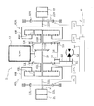
例えば、図9に示すように、動力伝達装置11と左右のスプロケット2L,2Rとの間に左右の遊星歯車機構40L,40Rが配置され、左右の遊星歯車機構40L,40Rと左右のスプロケット2L,2Rとの間に左右のステアリングブレーキ13L,13Rが配置されていてもよい。
For example, as shown in FIG. 9, left and right planetary gear mechanisms 40L and 40R are arranged between the power transmission device 11 and the left and right sprockets 2L and 2R, and the left and right planetary gear mechanisms 40L and 40R and the left and right sprockets 2L, The left and right steering brakes 13L and 13R may be arranged between the 2R and the left and right steering brakes 13L and 13R.
左右の遊星歯車機構40L,40Rは、左右のリングギア41L,41R、左右のプラネタリギア42L,42R、左右のサンギア43L,43R及び左右のキャリア44L,44Rを有する。
The left and right planetary gear mechanisms 40L and 40R have left and right ring gears 41L and 41R, left and right planetary gears 42L and 42R, left and right sun gears 43L and 43R, and left and right carriers 44L and 44R.
左右のステアリングクラッチ12L,12Rは、左右のサンギア43L,43Rに対して係合又は開放可能である。左ステアリングクラッチ12Lが左サンギア43Lに係合されて左サンギア43Lが制動状態になると、横軸20の回転は、左リングギア41L、左プラネタリギア42L及び左キャリア44Lを介して左出力軸21Lに伝達される。左ステアリングクラッチ12Lが左サンギア43Lから開放されて左サンギア43Lが自由回転状態になると、横軸20の回転は左出力軸21Lに伝達されない。このように、左ステアリングクラッチ12Lは、動力伝達装置11から左スプロケット2Lへの動力を伝達又は遮断可能である。同様に、右ステアリングクラッチ12Rも、動力伝達装置11から右スプロケット2Rへの動力を伝達又は遮断可能である。
The left and right steering clutches 12L and 12R can be engaged with or released from the left and right sun gears 43L and 43R. When the left steering clutch 12L is engaged with the left sun gear 43L and the left sun gear 43L is in the braking state, the rotation of the horizontal shaft 20 is transferred to the left output shaft 21L via the left ring gear 41L, the left planetary gear 42L and the left carrier 44L. Be transmitted. When the left steering clutch 12L is released from the left sun gear 43L and the left sun gear 43L is in a free rotation state, the rotation of the horizontal shaft 20 is not transmitted to the left output shaft 21L. In this way, the left steering clutch 12L can transmit or cut off the power from the power transmission device 11 to the left sprocket 2L. Similarly, the right steering clutch 12R can also transmit or cut off the power from the power transmission device 11 to the right sprocket 2R.
なお、図9に示す例において、左ステアリングクラッチ12Lは、アイドラギア50及びピニオンギア51を介してモータ52に連結され、右ステアリングクラッチ12Rは、第1トランスファギア53、副軸54、第2トランスファギア55、アイドラギア50及びピニオンギア51を介してモータ52に連結されている。左右のステアリングクラッチ12L,12Rが係合されている場合、モータ52の回転動力が、左右のステアリングクラッチ12L,12Rを介して左右のサンギア43L,43Rに伝達され、左右のサンギア43L,43Rが互いに逆回転することによって、作業機械は緩旋回又は信地旋回することができる。
In the example shown in FIG. 9, the left steering clutch 12L is connected to the motor 52 via the idler gear 50 and the pinion gear 51, and the right steering clutch 12R is the first transfer gear 53, the auxiliary shaft 54, and the second transfer gear. It is connected to the motor 52 via 55, an idler gear 50 and a pinion gear 51. When the left and right steering clutches 12L and 12R are engaged, the rotational power of the motor 52 is transmitted to the left and right sun gears 43L and 43R via the left and right steering clutches 12L and 12R, and the left and right sun gears 43L and 43R communicate with each other. By rotating in the reverse direction, the work machine can make a slow turn or a true turn.
ただし、モータ52は任意の構成要素である。モータ52を設置しない場合には、アイドラギア50及びピニオンギア51の少なくとも一方を固定すればよい。
However, the motor 52 is an arbitrary component. When the motor 52 is not installed, at least one of the idler gear 50 and the pinion gear 51 may be fixed.
1 ブルドーザ
2L,2R スプロケット(駆動輪)
3L,3R 履帯
4L,4R 走行装置
10 エンジン
11 動力伝達装置
12L,12R ステアリングクラッチ
13L,13R ステアリングブレーキ
30 制御部 1 Bulldozer 2L, 2R Sprocket (driving wheel)
3L, 3R Track 4L, 4R Traveling device 10 Engine 11 Power transmission device 12L, 12R Steering clutch 13L, 13R Steering brake 30 Control unit
2L,2R スプロケット(駆動輪)
3L,3R 履帯
4L,4R 走行装置
10 エンジン
11 動力伝達装置
12L,12R ステアリングクラッチ
13L,13R ステアリングブレーキ
30 制御部 1
3L,
Claims (6)
- エンジンと、
左右の履帯を駆動させる左右の駆動輪と、
前記エンジンの動力を前記左右の駆動輪に伝達する動力伝達装置と、
前記動力伝達装置と前記左右の駆動輪との間に配置され、動力を伝達又は遮断する左右のステアリングクラッチと、
前記左右のステアリングクラッチと前記左右の駆動輪との間に配置され、前記左右の駆動輪の回転を制動する左右のステアリングブレーキと、
前記左右のステアリングクラッチ及び前記左右のステアリングブレーキを制御することによって車両の旋回制御を実行する制御部と、
を備え、
前記制御部は、実旋回半径と目標旋回半径との偏差又は実方位と目標方位との偏差に基づいて、前記クラッチ制御と前記ブレーキ制御とを切り替える、
履帯式作業機械。 With the engine
The left and right drive wheels that drive the left and right tracks,
A power transmission device that transmits the power of the engine to the left and right drive wheels,
Left and right steering clutches arranged between the power transmission device and the left and right drive wheels to transmit or cut power.
Left and right steering brakes arranged between the left and right steering clutches and the left and right drive wheels to brake the rotation of the left and right drive wheels,
A control unit that executes vehicle turning control by controlling the left and right steering clutches and the left and right steering brakes.
With
The control unit switches between the clutch control and the brake control based on the deviation between the actual turning radius and the target turning radius or the deviation between the actual direction and the target direction.
Track type work machine. - エンジンと、
左右の履帯を駆動させる左右の駆動輪と、
前記エンジンからの動力を伝達する動力伝達装置と、
前記動力伝達装置から前記左右の駆動輪それぞれへの動力を伝達又は遮断する左右のステアリングクラッチと、
前記左右の駆動輪の回転を制動する左右のステアリングブレーキと、
前記左右のステアリングクラッチ及び前記左右のステアリングブレーキを制御することによって車両の旋回制御を実行する制御部と、
を備え、
前記制御部は、実旋回半径と目標旋回半径との偏差又は実方位と目標方位との偏差に基づいて、前記クラッチ制御と前記ブレーキ制御とを切り替える、
履帯式作業機械。 With the engine
The left and right drive wheels that drive the left and right tracks,
A power transmission device that transmits power from the engine,
Left and right steering clutches that transmit or cut off power from the power transmission device to the left and right drive wheels, respectively.
The left and right steering brakes that brake the rotation of the left and right drive wheels,
A control unit that executes vehicle turning control by controlling the left and right steering clutches and the left and right steering brakes.
With
The control unit switches between the clutch control and the brake control based on the deviation between the actual turning radius and the target turning radius or the deviation between the actual direction and the target direction.
Track type work machine. - 前記クラッチ制御において、前記制御部は、前記左右のステアリングクラッチのうち旋回方向側に位置する一方のステアリングクラッチを部分係合させ、かつ、前記左右のステアリングブレーキのうち前記旋回方向側に位置する一方のステアリングブレーキを開放させ、
前記ブレーキ制御において、前記制御部は、前記一方のステアリングクラッチを開放させ、かつ、前記一方のステアリングブレーキを完全係合又は部分係合させる、
請求項1又は2に記載の履帯式作業機械。 In the clutch control, the control unit partially engages one of the left and right steering clutches located on the turning direction side, and one of the left and right steering brakes located on the turning direction side. Release the steering brake of
In the brake control, the control unit releases the one steering clutch and fully or partially engages the one steering brake.
The track-type work machine according to claim 1 or 2. - 前記制御部は、
前記クラッチ制御で旋回制御を実行している場合において、前記実旋回半径が前記目標旋回半径より第1閾値以上大きいとき、前記クラッチ制御から前記ブレーキ制御に移行させ、
前記ブレーキ制御で旋回制御を実行している場合において、前記目標旋回半径が前記実旋回半径より第2閾値以上大きいとき、前記ブレーキ制御から前記クラッチ制御に移行させる、
請求項3に記載の履帯式作業機械。 The control unit
In the case where the turning control is executed by the clutch control, when the actual turning radius is larger than the target turning radius by the first threshold value or more, the clutch control is shifted to the brake control.
In the case where the turning control is executed by the brake control, when the target turning radius is larger than the actual turning radius by a second threshold value or more, the brake control is shifted to the clutch control.
The track-type work machine according to claim 3. - 前記実旋回半径は、前記左右のステアリングブレーキの出力回転数に基づいて算出される、
請求項1乃至4のいずれかに記載の履帯式作業機械。 The actual turning radius is calculated based on the output rotation speeds of the left and right steering brakes.
The track-type work machine according to any one of claims 1 to 4. - 前記目標旋回半径は、オペレータによる操向操作に用いられる操向レバーの操作量に応じて設定される、
請求項1乃至5のいずれかに記載の履帯式作業機械。 The target turning radius is set according to the amount of operation of the steering lever used for steering operation by the operator.
The track-type work machine according to any one of claims 1 to 5.
Priority Applications (3)
| Application Number | Priority Date | Filing Date | Title |
|---|---|---|---|
| CN202080047955.6A CN114026012B (en) | 2019-08-30 | 2020-06-29 | Crawler-type working machine |
| JP2021542577A JPWO2021039095A1 (en) | 2019-08-30 | 2020-06-29 | |
| US17/622,098 US20220242483A1 (en) | 2019-08-30 | 2020-06-29 | Crawler-type work machine |
Applications Claiming Priority (2)
| Application Number | Priority Date | Filing Date | Title |
|---|---|---|---|
| JP2019158994 | 2019-08-30 | ||
| JP2019-158994 | 2019-08-30 |
Publications (1)
| Publication Number | Publication Date |
|---|---|
| WO2021039095A1 true WO2021039095A1 (en) | 2021-03-04 |
Family
ID=74683652
Family Applications (1)
| Application Number | Title | Priority Date | Filing Date |
|---|---|---|---|
| PCT/JP2020/025575 WO2021039095A1 (en) | 2019-08-30 | 2020-06-29 | Crawler work machine |
Country Status (4)
| Country | Link |
|---|---|
| US (1) | US20220242483A1 (en) |
| JP (1) | JPWO2021039095A1 (en) |
| CN (1) | CN114026012B (en) |
| WO (1) | WO2021039095A1 (en) |
Citations (4)
| Publication number | Priority date | Publication date | Assignee | Title |
|---|---|---|---|---|
| JPH01501054A (en) * | 1986-10-10 | 1989-04-13 | キャタピラー インコーポレーテッド | Clutch and brake control system control device for tracked vehicles |
| JPH05124537A (en) * | 1991-02-21 | 1993-05-21 | Komatsu Ltd | Steering controller for caterpillar type vehicle |
| JPH101062A (en) * | 1996-06-13 | 1998-01-06 | Seirei Ind Co Ltd | Steering operation mechanism for traveling vehicle |
| JP2000142455A (en) * | 1998-11-16 | 2000-05-23 | Komatsu Ltd | Steering method of crawlered vihicle and steering device |
Family Cites Families (5)
| Publication number | Priority date | Publication date | Assignee | Title |
|---|---|---|---|---|
| JPS6175062A (en) * | 1984-09-21 | 1986-04-17 | Mitsubishi Heavy Ind Ltd | Steering controller for speed change steering system |
| JP3630612B2 (en) * | 2000-04-27 | 2005-03-16 | 株式会社クボタ | Work machine travel transmission structure |
| JP4497741B2 (en) * | 2001-03-29 | 2010-07-07 | 株式会社小松製作所 | Steering device for tracked vehicle |
| JP5205532B1 (en) * | 2012-05-01 | 2013-06-05 | 株式会社小松製作所 | Crawler work vehicle |
| JP5174976B1 (en) * | 2012-05-01 | 2013-04-03 | 株式会社小松製作所 | Crawler work vehicle |
-
2020
- 2020-06-29 CN CN202080047955.6A patent/CN114026012B/en active Active
- 2020-06-29 JP JP2021542577A patent/JPWO2021039095A1/ja active Pending
- 2020-06-29 US US17/622,098 patent/US20220242483A1/en active Pending
- 2020-06-29 WO PCT/JP2020/025575 patent/WO2021039095A1/en active Application Filing
Patent Citations (4)
| Publication number | Priority date | Publication date | Assignee | Title |
|---|---|---|---|---|
| JPH01501054A (en) * | 1986-10-10 | 1989-04-13 | キャタピラー インコーポレーテッド | Clutch and brake control system control device for tracked vehicles |
| JPH05124537A (en) * | 1991-02-21 | 1993-05-21 | Komatsu Ltd | Steering controller for caterpillar type vehicle |
| JPH101062A (en) * | 1996-06-13 | 1998-01-06 | Seirei Ind Co Ltd | Steering operation mechanism for traveling vehicle |
| JP2000142455A (en) * | 1998-11-16 | 2000-05-23 | Komatsu Ltd | Steering method of crawlered vihicle and steering device |
Also Published As
| Publication number | Publication date |
|---|---|
| CN114026012A (en) | 2022-02-08 |
| CN114026012B (en) | 2023-07-28 |
| JPWO2021039095A1 (en) | 2021-03-04 |
| US20220242483A1 (en) | 2022-08-04 |
Similar Documents
| Publication | Publication Date | Title |
|---|---|---|
| RU2701289C2 (en) | Agricultural working machine and method of assistance to steering control | |
| CN102171078B (en) | Traction control device | |
| US8418797B2 (en) | Work vehicle | |
| US10124805B2 (en) | Work vehicle and control method for work vehicle | |
| CN104684783B (en) | For the system and method for the rollback for controlling Working vehicle | |
| JPH10218005A (en) | Steering controller for caterpillar vehicle | |
| JPH11321700A (en) | Device and method for controlling steering of crawler machine | |
| CN105228850A (en) | For the control system of machine diff | |
| WO2012149859A1 (en) | Gear shifting control method, control device and grader having same | |
| WO2021039095A1 (en) | Crawler work machine | |
| EP1561672B1 (en) | Work machine with steering control | |
| JP2008099346A (en) | Crawler type traveling apparatus | |
| JP2008094214A (en) | Vehicle motion control apparatus | |
| US7657357B2 (en) | Vehicle motion control device | |
| US11708106B2 (en) | Steering systems and methods using active braking | |
| JP4796432B2 (en) | Work vehicle travel stop control device | |
| JP2682173B2 (en) | Differential control device for four-wheel drive vehicle | |
| JP2000142455A (en) | Steering method of crawlered vihicle and steering device | |
| JP7467054B2 (en) | Work vehicles | |
| WO2022137833A1 (en) | Crawler-type work machine | |
| JP2869469B2 (en) | Transmission control device for continuously variable transmission | |
| KR20240015311A (en) | Apparatus of controlling electric vehicle and method thereof | |
| JP3498709B2 (en) | Traveling gear for mobile agricultural machines | |
| JP2627165B2 (en) | Torque split type four-wheel drive vehicle | |
| JPH11198849A (en) | Paddy field working vehicle |
Legal Events
| Date | Code | Title | Description |
|---|---|---|---|
| 121 | Ep: the epo has been informed by wipo that ep was designated in this application |
Ref document number: 20858872 Country of ref document: EP Kind code of ref document: A1 |
|
| ENP | Entry into the national phase |
Ref document number: 2021542577 Country of ref document: JP Kind code of ref document: A |
|
| NENP | Non-entry into the national phase |
Ref country code: DE |
|
| 122 | Ep: pct application non-entry in european phase |
Ref document number: 20858872 Country of ref document: EP Kind code of ref document: A1 |