WO2021033546A1 - ハンドオーバ制御方法、中継装置、及びドナー装置 - Google Patents
ハンドオーバ制御方法、中継装置、及びドナー装置 Download PDFInfo
- Publication number
- WO2021033546A1 WO2021033546A1 PCT/JP2020/030008 JP2020030008W WO2021033546A1 WO 2021033546 A1 WO2021033546 A1 WO 2021033546A1 JP 2020030008 W JP2020030008 W JP 2020030008W WO 2021033546 A1 WO2021033546 A1 WO 2021033546A1
- Authority
- WO
- WIPO (PCT)
- Prior art keywords
- handover
- donor
- iab node
- relay device
- message
- Prior art date
- Legal status (The legal status is an assumption and is not a legal conclusion. Google has not performed a legal analysis and makes no representation as to the accuracy of the status listed.)
- Ceased
Links
Images


Classifications
-
- H—ELECTRICITY
- H04—ELECTRIC COMMUNICATION TECHNIQUE
- H04W—WIRELESS COMMUNICATION NETWORKS
- H04W36/00—Hand-off or reselection arrangements
- H04W36/02—Buffering or recovering information during reselection ; Modification of the traffic flow during hand-off
-
- H—ELECTRICITY
- H04—ELECTRIC COMMUNICATION TECHNIQUE
- H04W—WIRELESS COMMUNICATION NETWORKS
- H04W16/00—Network planning, e.g. coverage or traffic planning tools; Network deployment, e.g. resource partitioning or cells structures
- H04W16/24—Cell structures
- H04W16/26—Cell enhancers or enhancement, e.g. for tunnels, building shadow
-
- H—ELECTRICITY
- H04—ELECTRIC COMMUNICATION TECHNIQUE
- H04W—WIRELESS COMMUNICATION NETWORKS
- H04W88/00—Devices specially adapted for wireless communication networks, e.g. terminals, base stations or access point devices
- H04W88/02—Terminal devices
- H04W88/04—Terminal devices adapted for relaying to or from another terminal or user
-
- H—ELECTRICITY
- H04—ELECTRIC COMMUNICATION TECHNIQUE
- H04W—WIRELESS COMMUNICATION NETWORKS
- H04W84/00—Network topologies
- H04W84/02—Hierarchically pre-organised networks, e.g. paging networks, cellular networks, WLAN [Wireless Local Area Network] or WLL [Wireless Local Loop]
- H04W84/04—Large scale networks; Deep hierarchical networks
- H04W84/042—Public Land Mobile systems, e.g. cellular systems
- H04W84/047—Public Land Mobile systems, e.g. cellular systems using dedicated repeater stations
Definitions
- the present disclosure relates to a handover control method, a relay device, and a donor device used in a mobile communication system.
- 3GPP 3rd Generation Partnership Project
- IAB Integrated Access and Backhaul
- One or more relay devices intervene in the communication between the base station, which is a donor device, and the user device, and relay the communication.
- Such a relay device has a user device function and a base station function, and uses the user device function to perform wireless communication with a higher-level device (base station or higher-level relay device) and uses the base station function. Wireless communication with a lower-level device (user device or lower-level relay device).
- the wireless section between the user device and the relay device or base station is sometimes called an access link.
- the radio section between the relay device and the base station or other relay device is sometimes referred to as a backhaul link.
- the data transfer path is dynamically switched by integrating and multiplexing the data communication of the access link and the data communication of the backhaul link at layer 2 and dynamically allocating the radio resource to the backhaul link. The method is described.
- the handover device is handed over from the first donor device or the device under the first donor device to the second donor device or the device under the second donor device. It is a control method for performing.
- the first donor device transmits a first handover command instructing a handover of a lower device under the relay device to the lower device, and the relay device sends the first handover command.
- the transfer of the first handover command to the lower device is suspended until the handover of the relay device is executed, and the relay device responds to the execution of the handover of the relay device. It includes transferring the first handover command withholding the transfer to the lower device.
- the relay device is a relay device that performs a handover from the first donor device or the device under the first donor device to the second donor device or the device under the second donor device. ..
- the relay device receives a process of receiving a first handover command transmitted from the first donor device and instructing a handover of a lower device under the relay device, and after receiving the first handover command, the relay device.
- the process of suspending the transfer of the first handover command to the lower device until the handover of the relay device is executed, and the first handover command for which the transfer is suspended according to the execution of the handover of the relay device It has at least one processor that performs the process of transferring to the device.
- the donor device performs a handover of the relay device from the first donor device or the device under the first donor device to the second donor device or the device under the second donor device.
- the first donor device in the case.
- the donor device transmits a first message for suspending a transfer operation from the relay device to a lower device under the relay device until the handover of the relay device is executed, and a process of transmitting the first message to the relay device.
- the relay device is handed over from the first donor device (or the device under the first donor device) to the second donor device (or the device under the second donor device).
- the relay device needs to perform a handover between different donor devices.
- the relay device and the subordinate device under it perform a handover separately (that is, asynchronously), there is a concern that the communication of the subordinate device may be interrupted.
- the user device since the user device may exist as a lower device, it is possible to guarantee the backward compatibility of the user device when the handover procedure is significantly changed for the relay device and the operation of the user device as the lower device needs to be changed. It gets harder.
- an object of the present disclosure is to realize handover of a relay device between different donor devices while suppressing communication interruption of a lower device and guaranteeing backward compatibility.
- FIG. 1 is a diagram showing a configuration of a mobile communication system 1 according to an embodiment.
- the mobile communication system 1 is a fifth generation (5G) mobile communication system based on the 3GPP standard.
- the wireless access system in the mobile communication system 1 is NR (New Radio), which is a 5G wireless access system.
- NR New Radio
- LTE Long Term Evolution
- the mobile communication system 1 has a 5G core network (5GC) 10, a user device (UE: User Equipment) 100, a base station (called gNB) 200, and an IAB node 300.
- the IAB node 300 is an example of a relay device.
- the base station is an NR base station
- the base station may be an LTE base station (that is, eNB).
- the 5GC10 has an AMF (Access and Mobility Management Function) 11 and an UPF (User Plane Function) 12.
- the AMF 11 is a device that performs various mobility controls and the like for the UE 100.
- the AMF 11 manages information on the area in which the UE 100 is located by communicating with the UE 100 using NAS (Non-Access Stratum) signaling.
- the UPF 12 is a device that controls the transfer of user data and the like.
- the gNB 200 is connected to the 5GC10 via an interface called an NG interface. In FIG. 1, three gNB200-1 to gNB200-3 connected to 5GC10 are illustrated.
- the gNB 200 is a fixed wireless communication device that performs wireless communication with the UE 100. When the gNB 200 has a donor function, the gNB 200 may perform wireless communication with an IAB node that wirelessly connects to itself.
- the gNB 200 is connected to another gNB 200 that is adjacent to the gNB 200 via an inter-base station interface called an Xn interface.
- FIG. 1 shows an example in which gNB200-1 is connected to gNB200-2 and gNB200-2.
- Each gNB 200 manages one or more cells.
- Cell is used as a term to indicate the smallest unit of wireless communication area.
- the cell may be used as a term indicating a function or resource for wireless communication with the UE 100.
- One cell belongs to one carrier frequency.
- the UE 100 is a mobile wireless communication device that performs wireless communication with the gNB 200.
- the UE 100 may perform wireless communication with the IAB node 300.
- the UE 100 may be a device that performs wireless communication with the gNB 200 or the IAB node 300.
- the UE 100 is a mobile phone terminal, a tablet terminal, a notebook PC, a sensor or a device provided in the sensor, or a vehicle or a device provided in the vehicle.
- FIG. 1 shows an example in which UE 100-1 is wirelessly connected to gNB200-1, UE100-2 is wirelessly connected to IAB node 300-1, and UE100-3 is wirelessly connected to IAB node 300-2. ing.
- the UE 100-1 directly communicates with the gNB 200-1.
- the UE 100-2 indirectly communicates with the gNB 200-1 via the IAB node 300-1.
- the UE 100-3 indirectly communicates with the gNB 200-1 via the IAB node 300-1 and the IAB node 300-2.
- the IAB node 300 is a device (relay device) that intervenes in the communication between the eNB 200 and the UE 100 and relays the communication.
- FIG. 1 shows an example in which the IAB node 300-1 is wirelessly connected to the donor device gNB200-1 and the IAB node 300-2 is wirelessly connected to the IAB node 300-1.
- Each IAB node 300 manages a cell.
- the cell ID of the cell managed by the IAB node 300 may be the same as or different from the cell ID of the cell of the donor gNB200-1.
- the IAB node 300 has a UE function (user device function) and a gNB function (base station function). Such a UE function is sometimes called MT, and a gNB function is sometimes called DU.
- the IAB node 300 performs wireless communication with a higher device (gNB 200 or a higher IAB node 300) by its own UE function (MT), and also performs wireless communication with a lower device (UE 100 or a lower IAB node 300) by its own gNB function (DU). ) And wireless communication.
- the UE function (MT) means at least a part of the functions of the UE 100, and the IAB node 300 does not necessarily have all the functions of the UE 100.
- the gNB function (DU) means at least a part of the functions of the gNB 200, and the IAB node 300 does not necessarily have all the functions of the gNB 200.
- the gNB function (DU) does not have to have an RRC layer, a PDCP layer, or the like.
- the radio section between the UE 100 and the IAB node 300 or gNB 200 may be referred to as an access link (or Uu).
- the radio section between the IAB node 300 and the gNB 200 or other IAB node 300 may be referred to as a backhaul link (or Un).
- a backhaul link may be referred to as a fronthaul link.
- a millimeter wave band may be used for the access link and the backhaul link.
- the access link and the backhaul link may be multiplexed by time division and / or frequency division.
- FIG. 2 is a diagram showing the configuration of gNB 200.
- the gNB 200 has a wireless communication unit 210, a network communication unit 220, and a control unit 230.
- the wireless communication unit 210 is used for wireless communication with the UE 100 and wireless communication with the IAB node 300.
- the wireless communication unit 210 has a receiving unit 211 and a transmitting unit 212.
- the receiving unit 211 performs various receptions under the control of the control unit 230.
- the receiving unit 211 includes an antenna, converts the radio signal received by the antenna into a baseband signal (received signal), and outputs the radio signal to the control unit 230.
- the transmission unit 212 performs various transmissions under the control of the control unit 230.
- the transmission unit 212 includes an antenna, converts a baseband signal (transmission signal) output by the control unit 230 into a radio signal, and transmits the baseband signal (transmission signal) from the antenna.
- the network communication unit 220 is used for wired communication (or wireless communication) with 5GC10 and wired communication (or wireless communication) with another adjacent gNB200.
- the network communication unit 220 has a reception unit 221 and a transmission unit 222.
- the receiving unit 221 performs various types of reception under the control of the control unit 230.
- the receiving unit 221 receives a signal from the outside and outputs the received signal to the control unit 230.
- the transmission unit 222 performs various transmissions under the control of the control unit 230.
- the transmission unit 222 transmits the transmission signal output by the control unit 230 to the outside.
- the control unit 230 performs various controls on the gNB 200.
- the control unit 230 includes at least one memory and at least one processor electrically connected to the memory.
- the memory stores a program executed by the processor and information used for processing by the processor.
- the processor may include a baseband processor and a CPU.
- the baseband processor modulates / demodulates and encodes / decodes the baseband signal.
- the CPU executes a program stored in the memory to perform various processes.
- the processor executes a process described later.
- FIG. 3 is a diagram showing the configuration of the IAB node 300.
- the IAB node 300 has a wireless communication unit 310 and a control unit 320.
- the IAB node 300 may have a plurality of wireless communication units 310.
- the wireless communication unit 310 is used for wireless communication with the gNB 200 (backhaul link) and wireless communication with the UE 100 (access link).
- the wireless communication unit 310 for backhaul link communication and the wireless communication unit 310 for access link communication may be provided separately.
- the wireless communication unit 310 has a receiving unit 311 and a transmitting unit 312.
- the receiving unit 311 performs various types of reception under the control of the control unit 320.
- the receiving unit 311 includes an antenna, converts the radio signal received by the antenna into a baseband signal (received signal), and outputs the radio signal to the control unit 320.
- the transmission unit 312 performs various transmissions under the control of the control unit 320.
- the transmission unit 312 includes an antenna, converts the baseband signal (transmission signal) output by the control unit 320 into a radio signal, and transmits the baseband signal (transmission signal) from the antenna.
- the control unit 320 performs various controls on the IAB node 300.
- the control unit 320 includes at least one memory and at least one processor electrically connected to the memory.
- the memory stores a program executed by the processor and information used for processing by the processor.
- the processor may include a baseband processor and a CPU.
- the baseband processor modulates / demodulates and encodes / decodes the baseband signal.
- the CPU executes a program stored in the memory to perform various processes.
- the processor executes a process described later.
- FIG. 4 is a diagram showing the configuration of the UE 100. As shown in FIG. 4, the UE 100 has a wireless communication unit 110 and a control unit 120.
- the wireless communication unit 110 is used for wireless communication on the access link, that is, wireless communication with the gNB 200 and wireless communication with the IAB node 300.
- the wireless communication unit 110 has a receiving unit 111 and a transmitting unit 112.
- the receiving unit 111 performs various types of reception under the control of the control unit 120.
- the receiving unit 111 includes an antenna, converts the radio signal received by the antenna into a baseband signal (received signal), and outputs the radio signal to the control unit 120.
- the transmission unit 112 performs various transmissions under the control of the control unit 120.
- the transmission unit 112 includes an antenna, converts a baseband signal (transmission signal) output by the control unit 120 into a radio signal, and transmits the baseband signal (transmission signal) from the antenna.
- the control unit 120 performs various controls on the UE 100.
- the control unit 120 includes at least one memory and at least one processor electrically connected to the memory.
- the memory stores a program executed by the processor and information used for processing by the processor.
- the processor may include a baseband processor and a CPU.
- the baseband processor modulates / demodulates and encodes / decodes the baseband signal.
- the CPU executes a program stored in the memory to perform various processes.
- the processor executes a process described later.
- FIG. 5 is a diagram showing an example of a user plane protocol stack configuration.
- FIG. 5 shows an example of a protocol stack configuration relating to user data transmission between the UE 100-3 shown in FIG. 1 and the UPF 12 of the 5GC10.
- UPF12 includes GTP-U (GPRS Tunneling Protocol for User Plane), UDP (User Datagram Protocol), IP (Internet Protocol), and Layer 1 / Layer 2 (L1 / L2).
- GTP-U GPRS Tunneling Protocol for User Plane
- UDP User Datagram Protocol
- IP Internet Protocol
- L1 / L2 Layer 1 / Layer 2
- the gNB200-1 (donor gNB) is provided with a protocol stack corresponding to these.
- gNB200-1 has an aggregation unit (CU: Central Unit) and a distribution unit (DU: Distributed Unit).
- the CU has each layer of PDCP (Packet Data Convergence Protocol) or higher in the protocol stack of the wireless interface, and the DU has each layer below the RLC (Radio Link Control), and the CU and the CU via an interface called the F1 interface.
- the DU is connected.
- the CU has SDAP (Service Data Adaptation Protocol), PDCP, IP, and L1 / L2.
- SDAP Service Data Adaptation Protocol
- PDCP Packet Control Protocol
- IP Packet Control Protocol
- L1 / L2 Low-power Packet Control Protocol
- the SDAP and PDCP of the CU communicate with the SDAP and PDCP of the UE 100 via the DU, the IAB node 300-1 and the IAB node 300-2.
- the DU has an RLC, an adaptation layer (Adapt), a MAC (Medium Access Control), and a PHY (Physical layer) in the protocol stack of the wireless interface.
- RLC Radio Link Control
- Adapt adaptation layer
- MAC Medium Access Control
- PHY Physical layer
- These protocol stacks are protocol stacks for gNB.
- the adaptation layer and RLC (S-RLC) may have an opposite hierarchical relationship.
- the adaptation layer may be referred to as the backhaul adaptation protocol (BAP) layer.
- BAP backhaul adaptation protocol
- the IAB node 300-1 is provided with the protocol stack ST1 for the UE corresponding to these. Further, the IAB node 300-1 is provided with the protocol stack ST2 for gNB. Both the protocol stack ST1 and the protocol stack ST2 are composed of layers (each sublayer) below layer 2. That is, the IAB node 300-1 is a layer 2 relay device that relays user data using each layer of layer 2 or lower. The IAB node 300-1 relays data without using a layer of layer 3 or higher (specifically, a layer of PDCP or higher).
- the IAB node 300-2 has a protocol stack configuration similar to that of the IAB node 300-1.
- each of the gNB 200-1, the IAB node 300-1, the IAB node 300-2, and the UE 100-3 has an RRC (Radio Resource Control) corresponding to layer 3.
- RRC Radio Resource Control
- An RRC connection is established between the RRC of gNB200-1 (donor gNB) and the RRC of IAB node 300-1, and RRC messages are transmitted and received using this RRC connection. Further, an RRC connection is established between the RRC of the gNB200-1 and the RRC of the IAB node 300-2, and an RRC message is transmitted / received using this RRC connection. Further, an RRC connection is established between the RRC of gNB200-1 and the RRC of UE100-3, and RRC messages are transmitted and received using this RRC connection.
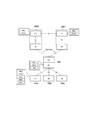
- FIG. 6 is a diagram showing an operation scenario of the mobile communication system 1 according to the embodiment.
- the IAB node 300 is handed over from the first donor device 200S to the second donor device 200T.
- the first donor device 200S and the second donor device 200T are gNB200 different from each other.
- donor device 200 when the first donor device 200S and the second donor device 200T are not particularly distinguished, they are simply referred to as "donor device 200".
- Each donor device 200 has a CU and a DU.
- the CU and DU are connected to each other via the F1 interface.
- the CU has an upper layer (RRC layer and PDCP layer).
- the DU has lower layers (RLC layer, MAC layer, and PHY layer).
- RRC layer and PDCP layer The DU has lower layers (RLC layer, MAC layer, and PHY layer).
- Xn interface Between the CU of the first donor device 200S and the CU of the second donor device 200T, there is an Xn interface which is an interface between base stations.
- inter-CU handover of the IAB node 300 the scenario in which the IAB node 300 is handed over from the first donor device 200S to the second donor device 200T is referred to as "inter-CU handover of the IAB node 300".
- FIG. 6 illustrates a scenario in which the inter-CU handover of the IAB node 300 is performed from the first donor device 200S to the second donor device 200T, but the device under the first donor device 200S (first donor device 200S).
- the inter-CU handover of the IAB node 300 may be performed from the lower IAB node) to the device under the second donor device 200T (the lower IAB node of the second donor device 200T).
- one or more IAB nodes may exist on the path between the IAB node 300 and the first donor device 200S before the inter-CU handover of the IAB node 300.
- one or more IAB nodes may be present on the path between the IAB node 300 and the second donor device 200T.
- a plurality of UEs 100 are illustrated as subordinate devices under the IAB node 300, but a subordinate IAB node may exist under the IAB node 300. That is, the lower device under the IAB node 300 means at least one of the UE 100 and the lower IAB node. In the following, an example in which the lower device under the IAB node 300 is the UE 100 will be mainly described.
- the UE 100 is connected to the DU of the IAB node 300 via the Uu interface.
- the IAB node 300 has MT and DU.
- the MT of the IAB node 300 is connected to the DU of the donor device 200 via the Uu interface.
- the Uu interface between the MT of the IAB node 300 and the DU of the donor device 200 is used as a backhaul link.
- the IAB node 300 has a BAP layer.
- the BAP layer may be positioned as an intermediate layer between the MT and DU, or at least a portion of the BAP layer may be incorporated into the MT and / or DU.
- Each of UE100 and MT has upper and lower layers (RRC layer, PDCP layer, RLC layer, MAC layer, and PHY layer).
- the lower layers (RLC layer, MAC layer, and PHY layer) of each UE 100 communicate with the DU (RLC layer, MAC layer, and PHY layer) of the IAB node 300.
- the upper layers (RRC layer and PDCP layer) of each UE 100 communicate with the CU (RRC layer and PDCP layer) of the donor device 200.
- the first donor device 200S transmits a first handover command instructing the handover of the UE 100 under the IAB node 300 to the UE 100.
- the first handover command may be a general handover command (RRC Reconfiguration with sync) transmitted and received in the RRC layer.
- the first handover command may be transmitted from the RRC layer of the CU of the first donor device 200S to the RRC layer of the UE 100.
- the IAB node 300 After receiving the first handover command addressed to the UE 100, the IAB node 300 suspends the transfer of the first handover command to the UE 100 until the handover of the IAB node 300 is executed. In other words, the IAB node 300 buffers the first handover command addressed to the UE 100 until the handover of the IAB node 300 is executed. Then, the IAB node 300 transfers the first handover command (that is, the buffered first handover command) for which the transfer is suspended to the UE 100 in response to the execution of the handover of the IAB node 300.
- the first handover command that is, the buffered first handover command
- the handover of the IAB node 300 and the handover of the UE 100 can be executed in synchronization, so that the communication of the UE 100 can be prevented from being interrupted.
- a general handover command transmitted / received in the RRC layer can be used, so that it is not necessary to change the operation of the UE 100, and it is easy to guarantee the backward compatibility of the UE 100.
- the first donor device 200S transmits the first handover command, and then transmits the second handover command instructing the handover of the IAB node 300 to the IAB node 300.
- the second handover command may be a general handover command (RRC Reconfiguration with sync) transmitted and received in the RRC layer.
- the second handover command may be transmitted from the RRC layer of the CU of the first donor device 200S to the RRC layer of the MT of the IAB node 300.
- the IAB node 300 executes the handover of the IAB node 300 in response to the reception of the second handover command.
- the first donor device 200S transmits a first message to the IAB node 300 for suspending the transfer operation to the UE 100 before transmitting the first handover command.
- the IAB node 300 suspends the transfer of the first handover command to the UE 100 in response to receiving the first message from the first donor device 200S.
- the first donor device 200S can control whether or not the transfer of the first handover command should be suspended by the first donor device 200S.
- the IAB node 300 does not suspend the transfer of the handover command from the donor device 200 to the UE 100. You may.
- the UE SRB Suspend message may be an RRC message (for example, an RRC Configuration message) transmitted to the MT of the IAB node 300, or an F1 message transmitted to the DU of the IAB node 300.
- RRC Configuration message transmitted to the MT of the IAB node 300
- F1 message transmitted to the DU of the IAB node 300.
- the UE SRB Suspend message is the SRB number to suspend (0, 1, 2, etc .: However, only SRB2 is actually the target), the backhaul bearer ID (RLC channel ID) associated with the SRB, and the DU that performs the suspend operation. It may include at least one of the ID and the expiration date of the suspend operation (timer value: the suspend operation is canceled when the timer expires).
- the UE SRB Suspend message may be a message that suspends a bearer for the UE 100 (lower device), specifically, an SRB (Signaling Radio Bearer).
- the UE SRB Suspend message may be a message that suspends RRC message transmission for the UE 100 (lower device).
- the RRC layer of MT or the F1 application protocol (F1AP) of DU may give a suspend instruction to the BAP layer.
- the BAP layer suspends the SRB or RRC message transmission and buffers the data received from the higher level.
- data buffering may be performed at a layer other than BAP.
- the second donor device 200T transmits a second message to the IAB node 300 for executing (resume) the transfer of the first handover command to the UE 100.
- the IAB node 300 transfers the first handover command withholding the transfer to the UE 100 in response to receiving the second message from the second donor device 200T.
- the UE SRB Resume message may be an RRC message (for example, an RRC Configuration message) transmitted to the MT of the IAB node 300, or an F1 message transmitted to the DU of the IAB node 300.
- RRC for example, an RRC Configuration message
- F1 message transmitted to the DU of the IAB node 300.
- the information element "UE SRB Suspend” is set to "False” (or the IE). If there is no), it indicates that the SRB suspend operation for the UE 100 is canceled (or resumed when the SRB is suspended).
- the UE SRB Resume message is the SRB number (0, 1, 2, etc .: only SRB2 is actually the target) to release the suspend, the backhaul bearer ID (RLC channel ID) associated with the SRB, and the suspend release. It may contain at least one of the IDs of the DUs to be used.
- the UE SRB Resumé message may be a bearer for the UE 100 (lower device), specifically, a message for resuming the SRB.
- the UE SRB Resumé message may be a message that resumes RRC message transmission for the UE 100 (lower device).
- the RRC layer of the MT or the F1 application protocol (F1AP) of the DU may issue a resume instruction to the BAP layer.
- the BAP layer resumes the SRB or RRC message transmission and forwards the buffered RRC message to the UE 100.
- the UE SRB Resume message is not essential signaling and can be omitted.
- the IAB node 300 may implicitly determine the resume and perform the above operation by transmitting and receiving the RRC Reconfiguration Complete message to and from the second donor device 200T.
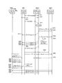
- FIG. 7 is a diagram showing an example of an operation sequence of the inter-CU handover according to one embodiment.
- the first donor device 200S which is the handover source (source) of the IAB node 300 is referred to as “S-IAB donor”
- the second donor device 200T which is the handover destination (target) of the IAB node 300 is referred to as “T”.
- -IAB node "is written.
- step S11 the MT of the IAB node 300 establishes an RRC connection with the first donor device 200S and enters a connected state (RRC Connected).
- step S12 each UE 100 establishes an RRC connection with the first donor device 200S and enters a connected state.
- the MT of the IAB node 300 transmits a measurement report (Meas. Report) message including the measurement result of the radio state of each cell to the first donor device 200S.
- the measurement report message may indicate that the radio state of the cell of the first donor device 200S has deteriorated and / or that the radio state of the cell of the second donor device 200T has improved. ..
- step S14 the CU of the first donor device 200S determines the inter-CU handover of the IAB node 300 from the first donor device 200S to the second donor device 200T based on the measurement report message from the IAB node 300 (HO). node).
- step S15 the CU of the first donor device 200S transmits a handover request (HO Request) message for the inter-CU handover of the IAB node 300 to the second donor device 200T.
- HO Request handover request
- the signaling between the first donor device 200S and the second donor device 200T is transmitted and received directly via the Xn interface, but the first donor device 200S and the second donor device 200T The signaling between them may be indirectly transmitted and received via 5GC10 (specifically, AMF11).
- 5GC10 specifically, AMF11
- the handover request message in step S15 includes information for handover of the IAB node 300.
- this handover request message may include an identifier indicating that the type of handover is the inter-CU handover of the IAB node.
- the handover request message in step S15 may further include information for handover of the UE 100 (for example, a list including the Xn AP ID and the context of each UE 100). That is, the handover request (UE Group HO Request) message in step S18, which will be described later, may be integrated with the handover request message in step S15.
- the handover request (UE Group HO Request) message in step S18 which will be described later, may be integrated with the handover request message in step S15.
- step S16 the CU of the second donor device 200T transmits an acknowledgment (ACK) message to the handover request of step S15 to the first donor device 200S.
- ACK acknowledgment
- step S17 the CU of the first donor device 200S transmits the above-mentioned UE SRB Suspend message to the IAB node 300 in response to the reception of the acknowledgment message from the second donor device 200T.
- the first donor The device 200S transmits a UE SRB Suspend message to the IAB node 300.
- the first donor device 200S transmits a handover request (UE Group HO Request) message for the inter-CU handover of the group of the UE 100 to the second donor device 200T.
- the handover request message in step S18 includes information for handover of the UE 100 (for example, a list including the Xn AP ID and the context of each UE 100).
- step S19 the CU of the second donor device 200T transmits an acknowledgment (ACK) message to the handover request of step S18 to the first donor device 200S.
- ACK acknowledgment
- the CU of the first donor device 200S transmits a first handover command (UE HO Command) addressed to each UE 100 to the IAB node 300 in response to receiving an acknowledgment message from the second donor device 200T.
- the first handover command instructs the handover of the UE 100 (inter-CU handover) from the first donor device 200S to the second donor device 200T.
- the CU of the first donor device 200S sends an affirmative response message to the integrated handover request message from the second donor device 200T.
- the first handover command (UE HO Command) addressed to each UE 100 is transmitted to the IAB node 300.
- the IAB node 300 Since the IAB node 300 has received the UE SRB Suspend message in step S17, it suspends the transfer of the first handover command to the UE 100.
- step S23 the CU of the first donor device 200S issues a second handover command (HO Command) instructing the handover of the IAB node 300 (inter-CU handover) from the first donor device 200S to the second donor device 200T. Send to 300.
- HO Command second handover command
- step S24 the MT of the IAB node 300 performs random access (Random Access) to the DU of the second donor device 200T in response to the reception of the second handover command.
- step S25 the MT of the IAB node 300 ends the random access to the second donor device 200T, and transmits an RRC Reconfiguration Complete message indicating the end of the handover to the CU of the second donor device 200T.
- step S26 the CU of the second donor device 200T transmits the above-mentioned UE SRB Reason message to the IAB node 300.
- the UE SRB Resumé message is not essential signaling and can be omitted.
- steps S27 to S29 the DU of the IAB node 300 transfers the first handover command that has been suspended for transfer to each UE 100 to each UE 100.
- steps S30 to S32 each UE 100 performs random access (Random Access) to the DU of the first donor device 200S in response to the reception of the first handover command.
- steps S30 to S32 are not essential processes, and handover (RACH-less HO) that omits random access can be applied.
- each UE 100 transmits an RRC Configuration Complete message indicating the end of handover to the CU of the second donor device 200T.
- step S15 and the handover request message in step S18 in FIG. 7 are transmitted separately, a situation may occur in which the former is permitted (ACK) and the latter is rejected (NACK).
- the handover request message in step S18 is transmitted as one message in FIG. 7, it may be transmitted separately for each UE. In either case, the handover request message of step S18 may be rejected (NACK) for some UEs.
- the CU of the first donor device 200S may transmit an RRC Release message addressed to the UE 100, which is the target of the negative response, to the IAB node 300 in response to receiving the negative response message from the second donor device 200T. .. That is, the CU of the first donor device 200S may transmit an RRC Release message to the IAB node 300 in place of at least one of the first handover commands (UE HO Command) in steps S20 to S22.
- UE HO Command the first handover commands
- the DU of the IAB node 300 may suspend the transfer of the RRC Release message to the UE 100 according to the UE SRB Suspend message in step S17. For example, if the random access in step S24 fails and then the first donor device 200S redetermines the inter-CU handover of the IAB node 300, the connection between the UE 100, which is the target of NACK, and the first donor device 200S Is preferably maintained. In this case, the DU of the IAB node 300 does not send the RRC Release message to the UE 100. The MT of the IAB node 300 may notify the IAB donor 200S that the pending RRC Release message has not been transmitted (that is, the RRC Release Cancel message).
- the DU of the IAB node 300 may suspend the transfer of the RRC Release message to the UE 100 according to the UE SRB Suspend message in step S17, and may transmit the RRC Release message to the UE 100 after steps S23 to S26 at the same timing as steps S27 to S29. ..
- the DU of the IAB node 300 may immediately transfer the RRC Release message to the UE 100. If the connection between the UE 100 that is the target of NACK, that is, that is determined that the handover cannot be performed, and the IAB node 300 is released, the UE 100 can quickly establish a connection with another IAB node.
- the base station in the mobile communication system 1 may be an eNB which is an LTE base station.
- the core network in the mobile communication system 1 may be an EPC (Evolved Packet Core).
- the gNB may be connected to the EPC
- the eNB may be connected to the 5GC
- the gNB and the eNB may be connected via the inter-base station interface (Xn interface, X2 interface).
- a program for causing a computer to execute each process according to the above-described embodiment may be provided.
- the program may also be recorded on a computer-readable medium.
- Computer-readable media can be used to install programs on a computer.
- the computer-readable medium on which the program is recorded may be a non-transient recording medium.
- the non-transient recording medium is not particularly limited, but may be, for example, a recording medium such as a CD-ROM or a DVD-ROM.
- a chipset composed of a memory for storing a program for executing each process performed by the UE 100, the gNB 200, or the IAB node 300 and a processor for executing the program stored in the memory may be provided.
Landscapes
- Engineering & Computer Science (AREA)
- Computer Networks & Wireless Communication (AREA)
- Signal Processing (AREA)
- Mobile Radio Communication Systems (AREA)
Priority Applications (2)
| Application Number | Priority Date | Filing Date | Title |
|---|---|---|---|
| JP2021540717A JP7274584B2 (ja) | 2019-08-21 | 2020-08-05 | ハンドオーバ制御方法、中継装置、及びドナー装置 |
| US17/675,703 US12192839B2 (en) | 2019-08-21 | 2022-02-18 | Handover control method, relay apparatus, and donor apparatus |
Applications Claiming Priority (2)
| Application Number | Priority Date | Filing Date | Title |
|---|---|---|---|
| JP2019-151550 | 2019-08-21 | ||
| JP2019151550 | 2019-08-21 |
Related Child Applications (1)
| Application Number | Title | Priority Date | Filing Date |
|---|---|---|---|
| US17/675,703 Continuation US12192839B2 (en) | 2019-08-21 | 2022-02-18 | Handover control method, relay apparatus, and donor apparatus |
Publications (1)
| Publication Number | Publication Date |
|---|---|
| WO2021033546A1 true WO2021033546A1 (ja) | 2021-02-25 |
Family
ID=74661019
Family Applications (1)
| Application Number | Title | Priority Date | Filing Date |
|---|---|---|---|
| PCT/JP2020/030008 Ceased WO2021033546A1 (ja) | 2019-08-21 | 2020-08-05 | ハンドオーバ制御方法、中継装置、及びドナー装置 |
Country Status (3)
| Country | Link |
|---|---|
| US (1) | US12192839B2 (https=) |
| JP (1) | JP7274584B2 (https=) |
| WO (1) | WO2021033546A1 (https=) |
Cited By (9)
| Publication number | Priority date | Publication date | Assignee | Title |
|---|---|---|---|---|
| JP2022007702A (ja) * | 2020-06-26 | 2022-01-13 | Kddi株式会社 | 中継装置のハンドオーバ処理を実行するための、中継装置、通信装置、制御方法、および、プログラム |
| JP2022007701A (ja) * | 2020-06-26 | 2022-01-13 | Kddi株式会社 | 中継装置のハンドオーバ処理を実行するための、基地局装置、中継装置、制御方法、および、プログラム |
| US11306372B2 (en) | 2019-03-07 | 2022-04-19 | Mitsubishi Power, Ltd. | Cobalt-based alloy powder, cobalt-based alloy sintered body, and method for producing cobalt-based alloy sintered body |
| US11325189B2 (en) | 2017-09-08 | 2022-05-10 | Mitsubishi Heavy Industries, Ltd. | Cobalt based alloy additive manufactured article, cobalt based alloy product, and method for manufacturing same |
| US11414728B2 (en) | 2019-03-07 | 2022-08-16 | Mitsubishi Heavy Industries, Ltd. | Cobalt based alloy product, method for manufacturing same, and cobalt based alloy article |
| US11427893B2 (en) | 2019-03-07 | 2022-08-30 | Mitsubishi Heavy Industries, Ltd. | Heat exchanger |
| US11499208B2 (en) | 2019-03-07 | 2022-11-15 | Mitsubishi Heavy Industries, Ltd. | Cobalt based alloy product |
| US11613795B2 (en) | 2019-03-07 | 2023-03-28 | Mitsubishi Heavy Industries, Ltd. | Cobalt based alloy product and method for manufacturing same |
| JP2024508928A (ja) * | 2021-03-04 | 2024-02-28 | 華為技術有限公司 | 通信方法およびデバイス |
Citations (1)
| Publication number | Priority date | Publication date | Assignee | Title |
|---|---|---|---|---|
| WO2017195823A1 (ja) * | 2016-05-13 | 2017-11-16 | 京セラ株式会社 | 無線端末及び基地局 |
Family Cites Families (6)
| Publication number | Priority date | Publication date | Assignee | Title |
|---|---|---|---|---|
| WO2011020229A1 (zh) * | 2009-08-17 | 2011-02-24 | 上海贝尔股份有限公司 | 在中继链路上处理数据的方法和相关设备 |
| US20120252355A1 (en) * | 2011-04-04 | 2012-10-04 | Qualcomm Incorporated | Apparatus and method for handing over relays |
| US9554307B2 (en) * | 2012-05-07 | 2017-01-24 | Telefonaktiebolaget Lm Ericsson (Publ) | Communication apparatus and mobility method for mobile relay of backhaul links |
| US9445311B2 (en) * | 2012-06-22 | 2016-09-13 | Lg Electronics Inc. | Method and apparatus for transmitting indication in wireless communication system |
| US11700565B2 (en) * | 2018-09-18 | 2023-07-11 | Qualcomm Incorporated | Management of radio link failure in wireless backhaul |
| EP4014693A4 (en) * | 2019-08-16 | 2023-08-30 | Nokia Solutions and Networks Oy | CONTROL OF OPERATIONS OF AN INTEGRATED ACCESS AND BACKHAUL (IAB) NODE |
-
2020
- 2020-08-05 WO PCT/JP2020/030008 patent/WO2021033546A1/ja not_active Ceased
- 2020-08-05 JP JP2021540717A patent/JP7274584B2/ja active Active
-
2022
- 2022-02-18 US US17/675,703 patent/US12192839B2/en active Active
Patent Citations (1)
| Publication number | Priority date | Publication date | Assignee | Title |
|---|---|---|---|---|
| WO2017195823A1 (ja) * | 2016-05-13 | 2017-11-16 | 京セラ株式会社 | 無線端末及び基地局 |
Non-Patent Citations (2)
| Title |
|---|
| HUAWEI: "Inter IAB donor- CU topology adaptation[ online", 3GPP TSG RAN WG3 #105 R3-194347, vol. RAN WG3, 17 August 2019 (2019-08-17), pages 1 - 3, XP051770539 * |
| ZTE, SANECHIPS: "Discussion on network-controlled IAB migration handling", 3GPP TSG RAN WG3 #103 R3-190542, vol. RAN WG3, 15 February 2019 (2019-02-15), XP051604480 * |
Cited By (16)
| Publication number | Priority date | Publication date | Assignee | Title |
|---|---|---|---|---|
| US11325189B2 (en) | 2017-09-08 | 2022-05-10 | Mitsubishi Heavy Industries, Ltd. | Cobalt based alloy additive manufactured article, cobalt based alloy product, and method for manufacturing same |
| US11499208B2 (en) | 2019-03-07 | 2022-11-15 | Mitsubishi Heavy Industries, Ltd. | Cobalt based alloy product |
| US11613795B2 (en) | 2019-03-07 | 2023-03-28 | Mitsubishi Heavy Industries, Ltd. | Cobalt based alloy product and method for manufacturing same |
| US11306372B2 (en) | 2019-03-07 | 2022-04-19 | Mitsubishi Power, Ltd. | Cobalt-based alloy powder, cobalt-based alloy sintered body, and method for producing cobalt-based alloy sintered body |
| US11414728B2 (en) | 2019-03-07 | 2022-08-16 | Mitsubishi Heavy Industries, Ltd. | Cobalt based alloy product, method for manufacturing same, and cobalt based alloy article |
| US11427893B2 (en) | 2019-03-07 | 2022-08-30 | Mitsubishi Heavy Industries, Ltd. | Heat exchanger |
| JP7607172B2 (ja) | 2020-06-26 | 2024-12-26 | Kddi株式会社 | 中継装置のハンドオーバ処理を実行するための、中継装置、通信装置、制御方法、および、プログラム |
| JP2022007701A (ja) * | 2020-06-26 | 2022-01-13 | Kddi株式会社 | 中継装置のハンドオーバ処理を実行するための、基地局装置、中継装置、制御方法、および、プログラム |
| JP7511400B2 (ja) | 2020-06-26 | 2024-07-05 | Kddi株式会社 | 中継装置のハンドオーバ処理を実行するための、基地局装置、中継装置、制御方法、および、プログラム |
| JP7514122B2 (ja) | 2020-06-26 | 2024-07-10 | Kddi株式会社 | 中継装置のハンドオーバ処理を実行するための、中継装置、通信装置、制御方法、および、プログラム |
| JP2024123263A (ja) * | 2020-06-26 | 2024-09-10 | Kddi株式会社 | 中継装置のハンドオーバ処理を実行するための、中継装置、通信装置、制御方法、および、プログラム |
| JP2022007702A (ja) * | 2020-06-26 | 2022-01-13 | Kddi株式会社 | 中継装置のハンドオーバ処理を実行するための、中継装置、通信装置、制御方法、および、プログラム |
| US12513581B2 (en) | 2020-06-26 | 2025-12-30 | Kddi Corporation | Relay apparatus, communication apparatus, control method, and computer-readable storage medium for executing handover processing of relay apparatus |
| JP2024508928A (ja) * | 2021-03-04 | 2024-02-28 | 華為技術有限公司 | 通信方法およびデバイス |
| JP7635413B2 (ja) | 2021-03-04 | 2025-02-25 | 華為技術有限公司 | 通信方法およびデバイス |
| US12520203B2 (en) | 2021-03-04 | 2026-01-06 | Huawei Technologies Co., Ltd. | Communication method and device |
Also Published As
| Publication number | Publication date |
|---|---|
| JPWO2021033546A1 (https=) | 2021-02-25 |
| US12192839B2 (en) | 2025-01-07 |
| US20220174564A1 (en) | 2022-06-02 |
| JP7274584B2 (ja) | 2023-05-16 |
Similar Documents
| Publication | Publication Date | Title |
|---|---|---|
| JP7274584B2 (ja) | ハンドオーバ制御方法、中継装置、及びドナー装置 | |
| US12225598B2 (en) | Mobile communication system, relay node, and base station | |
| JP6280669B1 (ja) | 基地局、方法、及びシステム | |
| JP6857707B2 (ja) | 通信方法、ユーザ装置及びプロセッサ | |
| JP7581297B2 (ja) | 通信制御方法及び中継装置 | |
| JP2017526305A (ja) | ユーザー装置の基地局ハンドオーバ方法及び基地局、ユーザー装置 | |
| US12550015B2 (en) | Communication control method | |
| WO2020032129A1 (ja) | 中継装置 | |
| WO2021024821A1 (ja) | 通信制御方法 | |
| WO2023282251A1 (ja) | 通信制御方法 | |
| WO2016167212A1 (ja) | 基地局及び通信制御方法 | |
| US12426116B2 (en) | Communication control method | |
| JP2018174597A (ja) | ベアラ管理装置、方法及び通信システム | |
| WO2023140332A1 (ja) | 通信制御方法 |
Legal Events
| Date | Code | Title | Description |
|---|---|---|---|
| 121 | Ep: the epo has been informed by wipo that ep was designated in this application |
Ref document number: 20854213 Country of ref document: EP Kind code of ref document: A1 |
|
| ENP | Entry into the national phase |
Ref document number: 2021540717 Country of ref document: JP Kind code of ref document: A |
|
| NENP | Non-entry into the national phase |
Ref country code: DE |
|
| 122 | Ep: pct application non-entry in european phase |
Ref document number: 20854213 Country of ref document: EP Kind code of ref document: A1 |