WO2021028707A1 - Secondary battery short-circuiting assessment device, short-circuiting assessment method, and short-circuiting assessment system - Google Patents
Secondary battery short-circuiting assessment device, short-circuiting assessment method, and short-circuiting assessment system Download PDFInfo
- Publication number
- WO2021028707A1 WO2021028707A1 PCT/IB2019/000751 IB2019000751W WO2021028707A1 WO 2021028707 A1 WO2021028707 A1 WO 2021028707A1 IB 2019000751 W IB2019000751 W IB 2019000751W WO 2021028707 A1 WO2021028707 A1 WO 2021028707A1
- Authority
- WO
- WIPO (PCT)
- Prior art keywords
- secondary battery
- short
- circuit
- resistance
- electrolyte
- Prior art date
Links
Images


Classifications
-
- G—PHYSICS
- G01—MEASURING; TESTING
- G01R—MEASURING ELECTRIC VARIABLES; MEASURING MAGNETIC VARIABLES
- G01R31/00—Arrangements for testing electric properties; Arrangements for locating electric faults; Arrangements for electrical testing characterised by what is being tested not provided for elsewhere
- G01R31/36—Arrangements for testing, measuring or monitoring the electrical condition of accumulators or electric batteries, e.g. capacity or state of charge [SoC]
- G01R31/382—Arrangements for monitoring battery or accumulator variables, e.g. SoC
- G01R31/3842—Arrangements for monitoring battery or accumulator variables, e.g. SoC combining voltage and current measurements
-
- G—PHYSICS
- G01—MEASURING; TESTING
- G01R—MEASURING ELECTRIC VARIABLES; MEASURING MAGNETIC VARIABLES
- G01R31/00—Arrangements for testing electric properties; Arrangements for locating electric faults; Arrangements for electrical testing characterised by what is being tested not provided for elsewhere
- G01R31/36—Arrangements for testing, measuring or monitoring the electrical condition of accumulators or electric batteries, e.g. capacity or state of charge [SoC]
- G01R31/382—Arrangements for monitoring battery or accumulator variables, e.g. SoC
-
- G—PHYSICS
- G01—MEASURING; TESTING
- G01R—MEASURING ELECTRIC VARIABLES; MEASURING MAGNETIC VARIABLES
- G01R31/00—Arrangements for testing electric properties; Arrangements for locating electric faults; Arrangements for electrical testing characterised by what is being tested not provided for elsewhere
- G01R31/36—Arrangements for testing, measuring or monitoring the electrical condition of accumulators or electric batteries, e.g. capacity or state of charge [SoC]
- G01R31/389—Measuring internal impedance, internal conductance or related variables
-
- G—PHYSICS
- G01—MEASURING; TESTING
- G01R—MEASURING ELECTRIC VARIABLES; MEASURING MAGNETIC VARIABLES
- G01R31/00—Arrangements for testing electric properties; Arrangements for locating electric faults; Arrangements for electrical testing characterised by what is being tested not provided for elsewhere
- G01R31/50—Testing of electric apparatus, lines, cables or components for short-circuits, continuity, leakage current or incorrect line connections
- G01R31/52—Testing for short-circuits, leakage current or ground faults
-
- H—ELECTRICITY
- H01—ELECTRIC ELEMENTS
- H01M—PROCESSES OR MEANS, e.g. BATTERIES, FOR THE DIRECT CONVERSION OF CHEMICAL ENERGY INTO ELECTRICAL ENERGY
- H01M10/00—Secondary cells; Manufacture thereof
- H01M10/05—Accumulators with non-aqueous electrolyte
- H01M10/052—Li-accumulators
-
- H—ELECTRICITY
- H01—ELECTRIC ELEMENTS
- H01M—PROCESSES OR MEANS, e.g. BATTERIES, FOR THE DIRECT CONVERSION OF CHEMICAL ENERGY INTO ELECTRICAL ENERGY
- H01M10/00—Secondary cells; Manufacture thereof
- H01M10/05—Accumulators with non-aqueous electrolyte
- H01M10/056—Accumulators with non-aqueous electrolyte characterised by the materials used as electrolytes, e.g. mixed inorganic/organic electrolytes
- H01M10/0561—Accumulators with non-aqueous electrolyte characterised by the materials used as electrolytes, e.g. mixed inorganic/organic electrolytes the electrolyte being constituted of inorganic materials only
- H01M10/0562—Solid materials
-
- H—ELECTRICITY
- H01—ELECTRIC ELEMENTS
- H01M—PROCESSES OR MEANS, e.g. BATTERIES, FOR THE DIRECT CONVERSION OF CHEMICAL ENERGY INTO ELECTRICAL ENERGY
- H01M10/00—Secondary cells; Manufacture thereof
- H01M10/42—Methods or arrangements for servicing or maintenance of secondary cells or secondary half-cells
- H01M10/48—Accumulators combined with arrangements for measuring, testing or indicating the condition of cells, e.g. the level or density of the electrolyte
-
- H—ELECTRICITY
- H01—ELECTRIC ELEMENTS
- H01M—PROCESSES OR MEANS, e.g. BATTERIES, FOR THE DIRECT CONVERSION OF CHEMICAL ENERGY INTO ELECTRICAL ENERGY
- H01M4/00—Electrodes
- H01M4/02—Electrodes composed of, or comprising, active material
- H01M4/36—Selection of substances as active materials, active masses, active liquids
- H01M4/38—Selection of substances as active materials, active masses, active liquids of elements or alloys
- H01M4/40—Alloys based on alkali metals
- H01M4/405—Alloys based on lithium
-
- H—ELECTRICITY
- H01—ELECTRIC ELEMENTS
- H01M—PROCESSES OR MEANS, e.g. BATTERIES, FOR THE DIRECT CONVERSION OF CHEMICAL ENERGY INTO ELECTRICAL ENERGY
- H01M10/00—Secondary cells; Manufacture thereof
- H01M10/60—Heating or cooling; Temperature control
- H01M10/61—Types of temperature control
- H01M10/615—Heating or keeping warm
-
- H—ELECTRICITY
- H01—ELECTRIC ELEMENTS
- H01M—PROCESSES OR MEANS, e.g. BATTERIES, FOR THE DIRECT CONVERSION OF CHEMICAL ENERGY INTO ELECTRICAL ENERGY
- H01M10/00—Secondary cells; Manufacture thereof
- H01M10/60—Heating or cooling; Temperature control
- H01M10/63—Control systems
-
- Y—GENERAL TAGGING OF NEW TECHNOLOGICAL DEVELOPMENTS; GENERAL TAGGING OF CROSS-SECTIONAL TECHNOLOGIES SPANNING OVER SEVERAL SECTIONS OF THE IPC; TECHNICAL SUBJECTS COVERED BY FORMER USPC CROSS-REFERENCE ART COLLECTIONS [XRACs] AND DIGESTS
- Y02—TECHNOLOGIES OR APPLICATIONS FOR MITIGATION OR ADAPTATION AGAINST CLIMATE CHANGE
- Y02E—REDUCTION OF GREENHOUSE GAS [GHG] EMISSIONS, RELATED TO ENERGY GENERATION, TRANSMISSION OR DISTRIBUTION
- Y02E60/00—Enabling technologies; Technologies with a potential or indirect contribution to GHG emissions mitigation
- Y02E60/10—Energy storage using batteries
Definitions
- the present invention relates to a short circuit estimation device for a secondary battery, a short circuit estimation method, and a short circuit estimation system.
- Patent Document 1 a state detection method for detecting the state of a lithium secondary battery has been known (Patent Document 1).
- the battery is discharged to SOC 10% or less, the impedance of the discharged battery is measured, and the reaction is performed from the impedance circle obtained by plotting the real part and the imaginary part of the impedance in plane coordinates. Calculate the resistance value. Then, when the calculated reaction resistance value exceeds a predetermined threshold value, it is determined that the battery has deteriorated.
- An object to be solved by the present invention is to provide a short circuit estimation device for a secondary battery, a short circuit estimation method, and a short circuit estimation system that can predict an internal short circuit caused by lithium dendrite before the occurrence of a short circuit.
- the electrolyte resistance of the secondary battery and the reaction resistance of the secondary battery are calculated from the AC impedance, respectively, and the rate of change of the electrolyte resistance in a predetermined period is within a predetermined range, and the reaction resistance is a predetermined upper limit.
- the value becomes higher than the value it is estimated that an internal short circuit may occur, thereby solving the above problem.
- an internal short circuit caused by lithium dendrite can be predicted before a short circuit occurs.
- FIG. 1 is a block diagram showing a charge control system for a secondary battery according to the present embodiment.
- FIG. 2 is a plan view of the secondary battery according to the present embodiment.
- FIG. 3 is a cross-sectional view of the secondary battery along the line III-III of FIG.
- FIG. 4 plots the real axis component value (Z') and the imaginary axis component value (Z ′′) of the AC impedance measured by the impedance measuring instrument on the complex plane coordinates where the real axis and the imaginary axis are orthogonal to each other. It is a graph of the complex impedance plot (Nyquist plot; Cole Cole plot) including the arc locus obtained.
- FIG. 1 is a block diagram showing a charge control system for a secondary battery according to the present embodiment.
- FIG. 2 is a plan view of the secondary battery according to the present embodiment.
- FIG. 3 is a cross-sectional view of the secondary battery along the line III-III of FIG.
- FIG. 4 plots
- FIG. 5 is a graph showing the characteristics of the electrolyte resistance and the reaction resistance in the secondary battery according to the present embodiment.
- FIG. 6 is a graph showing the characteristics of the change in reaction resistance with respect to the current density in the secondary battery according to the present embodiment.
- FIG. 7 is a graph showing the characteristics of the change in reaction resistance with respect to the pressurization / heat treatment time in the secondary battery according to the present embodiment.
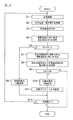
- FIG. 8 is a flowchart of a charge control process executed in the charge control system according to the present embodiment.
- FIG. 9 is a graph showing changes in the charging current and the reaction resistance of the secondary battery when the secondary battery according to the present embodiment is charged with a predetermined charging profile.
- FIG. 10 is a graph showing changes in the charging current and the reaction resistance of the secondary battery when charging is performed with a predetermined charging profile in the secondary battery according to the present embodiment.
- FIG. 11 is a diagram for explaining the evaluation results of Examples and Comparative Examples, and is a graph showing the characteristics of the electrolyte resistance and the reaction resistance.
- FIG. 1 is a diagram showing a configuration of a short circuit estimation system for a secondary battery according to the present embodiment.
- the secondary battery short-circuit estimation system according to the present embodiment determines whether or not there is a possibility of an internal short-circuit in the all-solid-state lithium-ion secondary battery.
- the short-circuit estimation system 1 includes a secondary battery 2, a voltage sensor 3, a temperature sensor 4, a voltage / current adjusting unit 5, a current sensor 6, an impedance measuring instrument 7, and a controller 8. , With an external power supply 9.
- the short-circuit estimation system shown in FIG. 1 is a system for charging the secondary battery 2 with the electric power of the external power source 9, and at this time, it is determined whether or not an internal short circuit of the secondary battery 2 may occur.
- the secondary battery 2 is an all-solid lithium ion secondary battery, and contains a positive electrode including a positive electrode active material layer capable of storing and releasing lithium ions and a negative electrode active material capable of storing and releasing lithium ions.
- the power generation element includes a negative electrode including a negative electrode active material layer, and a solid electrolyte layer interposed between the positive electrode active material layer and the negative electrode active material layer.
- the secondary battery 2 has an electrode tab, an electrode tab, and an exterior member accommodating the power generation element. The detailed structure and material of the secondary battery will be described later.
- the voltage sensor 3 is a sensor for detecting the input / output voltage of the secondary battery 2, and detects the cell voltage (voltage between terminals) between the positive electrode and the negative electrode of the secondary battery 2.
- the connection position of the voltage sensor 3 is not particularly limited as long as it can detect the cell voltage between the positive electrode and the negative electrode in the circuit connected to the secondary battery 2.
- the temperature sensor 4 measures the outer surface temperature (environmental temperature) of the secondary battery 2.
- the temperature sensor 4 is attached to, for example, the surface of the case (exterior body, housing) of the secondary battery 2.
- the voltage / current adjusting unit 5 is a circuit for adjusting the battery current and the battery voltage during charging and / or discharging of the secondary battery 2, and the current / current of the secondary battery 2 is based on a command from the controller 8. Adjust the voltage.
- the voltage / current adjusting unit 5 has a voltage conversion circuit or the like for converting the power output from the external power source into the charging voltage of the secondary battery.
- the current sensor 6 is a sensor for detecting the input / output current of the secondary battery 2.
- the current sensor 6 detects the current supplied from the voltage / current adjusting unit 5 to the secondary battery 2 when charging the secondary battery 2, and detects the current supplied from the secondary battery 2 to the voltage / current adjusting unit 5 when discharging. To do.
- the impedance measuring device 7 is connected to the secondary battery 2, and the AC perturbation current is passed through the secondary battery 2 as an input signal to acquire the response voltage corresponding to the AC current, whereby the AC impedance of the secondary battery 2 ( Complex impedance) is measured.
- the impedance measuring device 7 may be arbitrarily selected from those normally used as a general AC impedance measuring device.
- the impedance measuring device 7 may measure the AC impedance of the secondary battery 2 by changing the frequency of the AC perturbing current with time by the AC impedance method. Further, a plurality of AC perturbation currents having different frequencies may be applied at the same time.
- the method for measuring AC impedance in the AC impedance method is not particularly limited.
- an analog method such as the Lissajous method or the Bunryu bridge method, or a digital method such as a digital Fourier integral method or a fast Fourier transform method by applying noise can be appropriately adopted.
- a plurality of AC perturbing currents having different frequencies are applied to the secondary battery 2 to measure the AC impedance.
- a plurality of frequencies are typically about 1 MHz to 0.1 Hz, preferably 1 kHz to 0.1 Hz.
- the waveform of the AC perturbation current applied to the battery (for example, a sinusoidal wave).
- the amplitude and the like of the above are not particularly limited and are set arbitrarily.
- the measurement result of the AC impedance measured by the impedance measuring device 7 is sent to the controller 8 as the output of the impedance measuring device 7.
- the controller 8 has a CPU 81, a storage unit 82, and the like.
- the controller 8 is a control device for estimating the possibility of an internal short circuit in the secondary battery 2 based on the AC impedance of the secondary battery 2 measured by the impedance measuring device 7. Further, the controller 8 charges the secondary battery 2 based on the terminal voltage of the secondary battery 2 detected by the voltage sensor 3 and the charge / discharge current flowing through the secondary battery 2 detected by the current sensor 6. Control.
- the external power source 9 is a power source for charging the secondary battery 2.
- a three-phase 200V AC power source is used.
- the external power supply 9 may be a single-phase 100V or single-phase 200V AC power supply. Further, the external power supply 9 is not limited to alternating current, and may be a direct current power supply.
- FIG. 2 shows a plan view of the secondary battery 2 according to the present embodiment
- FIG. 3 shows a cross-sectional view of the secondary battery 2 along the line III-III of FIG.
- the secondary battery 2 is connected to a power generation element 101 having three positive electrode layers 102, seven electrolyte layers 103, and three negative electrode layers 104, and three positive electrode layers 102, respectively.
- the positive electrode tab 105, the negative electrode tab 106 connected to each of the three negative electrode layers 104, and the upper exterior member 107 and the lower exterior member 108 that house and seal the power generation element 101, the positive electrode tab 105, and the negative electrode tab 106, respectively. It is composed of and.
- the number of the positive electrode layer 102, the electrolyte layer 103, and the negative electrode layer 104 is not particularly limited, and one positive electrode layer 102, three electrolyte layers 103, and one negative electrode layer 104 may form the power generation element 101. Further, the number of positive electrode layers 102, electrolyte layer 103, and negative electrode layer 104 may be appropriately selected, if necessary.
- the positive electrode layer 102 constituting the power generation element 101 has a positive electrode side current collector 104a extending to the positive electrode tab 105 and a positive electrode active material layer formed on both main surfaces of a part of the positive electrode side current collector 104a. doing.
- the positive electrode side current collector 102a constituting the positive electrode layer 102 may be made of, for example, an electrochemically stable metal foil such as an aluminum foil, an aluminum alloy foil, a copper titanium foil, or a stainless steel foil. Nickel, iron, copper or the like may be used as the metal for the positive electrode side current collector 102a. In addition to these, a clad material of nickel and aluminum, a clad material of copper and aluminum, and the like may be used.
- a conductive resin may be used instead of the metal.
- the conductive resin can be composed of a non-conductive polymer material to which a conductive filler is added, if necessary.
- the non-conductive polymer material include polyethylene (PE; high density polyethylene (HDPE), low density polyethylene (LDPE), etc.), polypropylene (PP), polyethylene terephthalate (PET), and the like, which have excellent potential resistance.
- PE polyethylene
- HDPE high density polyethylene
- LDPE low density polyethylene
- PP polypropylene
- PET polyethylene terephthalate
- the conductive filler can be used without particular limitation as long as it is a conductive substance.
- a material having excellent conductivity, potential resistance, or lithium ion blocking property includes metals and conductive carbon.
- the metal is not particularly limited, and includes at least one metal selected from the group consisting of Ni, Ti, Al, Cu, Pt, Fe, Cr, Sn, Zn, In, and Sb, or at least one of these metals.
- Examples include alloys or metal oxides.
- the positive electrode active material layer constituting the positive electrode layer 102 is not particularly limited, but is a layered rock salt type active material such as LiCoO 2 , LiMnO 2 , LiNiO 2 , LiVO 2 , Li (Ni-Mn-Co) O 2 , LiMn 2 Spinel-type active materials such as O 4 , LiNi 0.5 Mn 1.5 O 4 , olivine-type active materials such as LiFePO 4 , LiMnPO 4 , and Si-containing active materials such as Li 2 FeSiO 4 and Li 2 MnSiO 4 are listed. Be done.
- the oxide active material other than the above include Li 4 Ti 5 O 12 .
- a composite oxide containing lithium and nickel is preferably used, and more preferably Li (Ni-Mn-Co) O 2 and a part of these transition metals are substituted with other elements (hereinafter, simply ". Also referred to as "NMC composite oxide”) is used. As described above, the NMC composite oxide also includes a composite oxide in which a part of the transition metal element is replaced with another metal element. Examples of other elements in that case include Ti, Zr, Nb, W, P and the like.
- a sulfur-based positive electrode active material may be used for the positive electrode active material layer.
- the sulfur-based positive electrode active material include particles or thin films of an organic sulfur compound or an inorganic sulfur compound, and the redox reaction of sulfur can be used to release lithium ions during charging and occlude lithium ions during discharging. Any substance that can be produced will do.
- the organic sulfur compound include a disulfide compound and a sulfur-modified polyacrylonitrile.
- the inorganic sulfur compound include sulfur (S), S-carbon composite, TiS 2 , TiS 3 , TiS 4 , NiS, NiS 2 , CuS, FeS 2 , Li 2 S, MoS 2 , MoS 3 and the like.
- a positive electrode active material other than the above may be used.
- Examples of the shape of the positive electrode active material include particulate (spherical, fibrous) and thin film.
- the content of the positive electrode active material in the positive electrode active material layer is not particularly limited.
- the positive electrode active material layer may further contain at least one of a solid electrolyte, a conductive auxiliary agent, and a binder, if necessary.
- Examples of the solid electrolyte include sulfide solid electrolytes and oxide solid electrolytes, and those exemplified as solid electrolytes capable of forming the electrolyte layer 103, which will be described later
- the conductive auxiliary agent is not particularly limited, but its shape is preferably particulate or fibrous.
- the shape of the particles is not particularly limited, and may be any shape such as powder, sphere, rod, needle, plate, columnar, indefinite, flint, and spindle. It doesn't matter.
- the average particle size (primary particle size) when the conductive auxiliary agent is in the form of particles is not particularly limited, but is preferably 0.01 to 10 ⁇ m from the viewpoint of the electrical characteristics of the battery.
- Binders include polybutylene terephthalate, polyethylene terephthalate, polyvinylidene fluoride (PVDF) (including compounds in which hydrogen atoms are replaced by other halogen elements), polyethylene, polypropylene, polymethylpentene, polybutene, polyethernitrile, and poly.
- PVDF polyvinylidene fluoride
- Tetrafluoroethylene polyacrylonitrile, polyimide, polyamide, ethylene-vinyl acetate copolymer, polyvinyl chloride, styrene-butadiene rubber (SBR), ethylene-propylene-diene copolymer, styrene-butadiene-styrene block copolymer and Thermoplastic polymers such as the hydrogenated product, styrene / isoprene / styrene block copolymer and the hydrogenated product; tetrafluoroethylene / hexafluoropropylene copolymer (FEP), tetrafluoroethylene / perfluoroalkyl vinyl ether common weight Fluororesin such as coalescence (PFA), ethylene / tetrafluoroethylene copolymer (ETFE), polychlorotrifluoroethylene (PCTFE), ethylene / chlorotrifluoroethylene copolymer (ECTFE),
- each positive electrode side current collector 102a constituting these three positive electrode layers 102 is joined to the positive electrode tab 105.
- the positive electrode tab 105 aluminum foil, aluminum alloy foil, copper foil, nickel foil, or the like can be used.
- the negative electrode layer 104 constituting the power generation element 101 includes a negative electrode side current collector 104a extending to the negative electrode tab 106 and a negative electrode active material layer formed on both main surfaces of a part of the negative electrode side current collector 104a. have.
- the negative electrode side current collector 104a of the negative electrode layer 104 is an electrochemically stable metal foil such as a nickel foil, a copper foil, a stainless steel foil, or an iron foil.
- the negative electrode active material layer constituting the negative electrode layer 104 is formed of a layer containing a lithium alloy.
- the lithium alloy is selected from, for example, lithium and at least gold (Au), magnesium (Mg), aluminum (Al), calcium (Ca), zinc (Zn), tin (Sn), and bismuth (Bi).
- An alloy with one kind of metal can be mentioned.
- the lithium alloy may be an alloy of lithium and two or more kinds of metals among the above-mentioned metals.
- Specific examples of the lithium alloy include, for example, lithium-gold alloy (Li-Au), lithium-magnesium alloy (Li-Mg), lithium-aluminum alloy (Li-Al), lithium-calcium alloy (Li-Ca), and the like. Examples thereof include a lithium-zinc alloy (Li-Zn), a lithium-tin alloy (Li-Sn), and a lithium-bismus alloy (Li-Bi).
- the negative electrode active material layer may be any one containing a lithium alloy, and its composition is not particularly limited.
- a metal other than lithium constituting the lithium alloy is "Me"
- the following It can be any aspect of (1) to (3).
- a layer including a layer made of lithium metal, a layer made of a lithium alloy, and a layer made of a metal other than lithium that is, Li layer / Li-Me layer / Me layer).
- the layer made of a lithium alloy is a layer on the side of the electrolyte layer 103 (a layer forming an interface with the electrolyte layer 103), and the above (3).
- the layer made of a metal other than lithium is the layer on the side of the electrolyte layer 103 (the layer forming the interface with the electrolyte layer 103).
- the intermediate layer is a layer between the lithium metal layer and the solid electrolyte, and is at least one of the lithium metals. It is desirable that a part and at least a part of the metal forming the intermediate layer are alloyed.
- the negative electrode includes the aspect (3) above, that is, a layer made of a lithium metal, a layer made of a lithium alloy, and a layer made of a metal other than lithium (that is, a Li layer / Li-Me layer / In the case of forming a Me layer), a lithium metal and a metal other than lithium are laminated to alloy these interface portions, whereby a layer made of a lithium alloy can be formed at these interfaces. ..
- the method of laminating the lithium metal and the metal other than lithium is not particularly limited, but is made of the lithium metal by depositing a metal other than lithium on the layer made of the lithium metal by vacuum vapor deposition or the like.
- a method of alloying these interfaces while forming a layer made of a metal other than lithium on the layer can be mentioned.
- a lithium metal is vapor-deposited on a layer made of a metal other than lithium by vacuum deposition or the like, and these interfaces are alloyed while forming a layer made of a lithium metal on a layer made of a metal other than lithium.
- the method etc. can be mentioned.
- the three negative electrode layers 104 are configured such that each negative electrode side current collector 104a constituting the negative electrode layer 104 is joined to a single negative electrode tab 106. ing. That is, in the secondary battery 2 of the present embodiment, each negative electrode layer 104 is joined to a single common negative electrode tab 106.
- the electrolyte layer 103 of the power generation element 101 prevents a short circuit between the positive electrode layer 102 and the negative electrode layer 104 described above, contains a solid electrolyte as a main component, and comprises the positive electrode active material layer and the negative electrode active material layer described above. It is a layer that intervenes between them.
- the solid electrolyte include a sulfide solid electrolyte, an oxide solid electrolyte, a polymer solid electrolyte, and the like, and a sulfide solid electrolyte is preferable.
- Examples of the sulfide solid electrolyte include LiI-Li 2 S-SiS 2 , LiI-Li 2 S-P 2 O 5 , LiI-Li 3 PO 4- P 2 S 5 , Li 2 S-P 2 S 5 , LiI-Li 3 PS 4 , LiI-LiBr-Li 3 PS 4 , Li 3 PS 4 , Li 2 S-P 2 S 5 , Li 2 S-P 2 S 5 -Li I, Li 2 S-P 2 S 5- Li 2 O, Li 2 S-P 2 S 5 -Li 2 OLiI, Li 2 S-SiS 2 , Li 2 S-SiS 2- LiI, Li 2 S-SiS 2- LiBr, Li 2 S-SiS 2- LiCl , Li 2 S-SiS 2- B 2 S 3- LiI, Li 2 S-SiS 2- P 2 S 5- LiI, Li 2 SB 2 S 3 , Li 2 SP 2 S 5- ZmSn (However , M, n
- the sulfide solid electrolyte may have, for example, a Li 3 PS 4 skeleton, a Li 4 P 2 S 7 skeleton, or a Li 4 P 2 S 6 skeleton. ..
- Examples of the sulfide solid electrolyte having a Li 3 PS 4 skeleton include LiI-Li 3 PS 4 , LiI-LiBr-Li 3 PS 4 , and Li 3 PS 4 .
- a Li-PS-based solid electrolyte called LPS for example, Li 7 P 3 S 11
- LPS Li-PS-based solid electrolyte
- the sulfide solid electrolyte for example, LGPS represented by Li (4-x) Ge (1-x) P x S 4 (x satisfies 0 ⁇ x ⁇ 1) may be used.
- the sulfide solid electrolyte is preferably a sulfide solid electrolyte containing a P element, and the sulfide solid electrolyte is more preferably a material containing Li 2 SP 2 S 5 as a main component.
- the sulfide solid electrolyte may contain halogens (F, Cl, Br, I).
- the sulfide solid electrolyte may be sulfide glass, crystallized sulfide glass, or a crystalline material obtained by the solid phase method.
- the sulfide glass can be obtained, for example, by performing mechanical milling (ball mill or the like) on the raw material composition.
- the crystallized sulfide glass can be obtained, for example, by heat-treating the sulfide glass at a temperature equal to or higher than the crystallization temperature.
- the ionic conductivity (for example, Li ion conductivity) of the sulfide solid electrolyte at room temperature (25 ° C.) is preferably 1 ⁇ 10 -5 S / cm or more, for example, 1 ⁇ 10 -4 S / cm. It is more preferably cm or more.
- the value of the ionic conductivity of the solid electrolyte can be measured by the AC impedance method.
- Examples of the oxide solid electrolyte include compounds having a NASICON type structure and the like.
- a compound having a NASICON type structure a compound (LAGP) represented by the general formula Li 1 + x Al x Ge 2-x (PO 4 ) 3 (0 ⁇ x ⁇ 2), a general formula Li 1 + x Al x Ti 2 Examples thereof include a compound (LATP) represented by ⁇ x (PO 4 ) 3 (0 ⁇ x ⁇ 2).
- LiLaTIO for example, Li 0.34 La 0.5 1TIO 3
- LiPON for example, Li 2.9 PO 3.3 N 0.46
- LiLaZrO for example, LiLaZrO
- the solid electrolyte layer 103 may further contain a binder in addition to the above-mentioned solid electrolyte.
- the binder is not particularly limited, but for example, the above-mentioned binder can be used.
- the content of the solid electrolyte is, for example, preferably in the range of 10 to 100% by mass, more preferably in the range of 50 to 100% by mass, and preferably in the range of 90 to 100% by mass. More preferred.
- the positive electrode layer 102 and the negative electrode layer 104 are alternately laminated via the electrolyte layer 103, and the electrolyte layer 103 is further laminated on the uppermost layer and the lowermost layer, respectively.
- the power generation element 101 is formed.
- the power generation element 101 configured as described above is housed and sealed in the upper exterior member 107 and the lower exterior member 108 (sealing means).
- the upper exterior member 107 and the lower exterior member 108 for sealing the power generation element 101 are, for example, a resin obtained by laminating both sides of a resin film such as polyethylene or polypropylene or a metal leaf such as aluminum with a resin such as polyethylene or polypropylene.
- the positive electrode tab 105 and the negative electrode tab 106 are provided with a seal film 109 at a portion that comes into contact with the upper exterior member 107 and the lower exterior member 108 in order to ensure adhesion to the upper exterior member 107 and the lower exterior member 108. It is provided.
- the seal film 109 is not particularly limited, but can be made of, for example, polyethylene, modified polyethylene, polypropylene, modified polypropylene, or a synthetic resin material having excellent electrolytic solution resistance and heat-sealing properties such as ionomer.
- the internal short circuit estimation control of the secondary battery 2 described below is executed by the impedance measuring device 7 and the controller 8. Further, the estimation control of the internal short circuit is executed during the charge control of the secondary battery 2.
- the charge control of the secondary battery 2 is executed by the voltage / current adjusting unit 5 and the controller 8.
- the controller 8 gradually increases the current until the charging voltage of the secondary voltage 2 reaches a predetermined upper limit voltage, and when the charging current of the secondary battery 2 reaches the set current, the current value becomes constant. (So-called constant current control; CC charging). While charging the secondary battery 2, the controller 8 acquires detected values from the voltage sensor 3 and the current sensor 6 and manages the current flowing through the secondary battery 2 and the voltage applied to the secondary battery 2. .. Further, the controller 8 manages the SOC of the secondary battery 2 based on the detection voltage of the voltage sensor 3. In the present embodiment, by charging the secondary battery 2 with the set current, the SOC of the secondary battery 2 increases, and the voltage of the secondary battery 2 gradually increases.
- the controller 8 When the voltage of the secondary battery 2 reaches the upper limit voltage, the controller 8 performs constant voltage charging (CV charging) at the upper limit voltage. While the voltage of the secondary battery 2 is maintained at the upper limit voltage, the charging current is attenuated as the SOC of the secondary battery 2 increases. Then, in the present embodiment, when the charging current is attenuated and drops to the cutoff current value, the charging of the secondary battery 20 is completed. In the present embodiment, the charging of the secondary battery 20 is controlled in this way.
- the charging method is not limited to the so-called CC-CV charging as described above, and other charging methods may be used.
- FIG. 4 plots the real axis component value (Z') and the imaginary axis component value (Z ′′) of the AC impedance measured by the impedance measuring device 7 on the complex plane coordinates in which the real axis and the imaginary axis are orthogonal to each other. It is a graph of the complex impedance plot (Nyquist plot; Cole Cole plot) including the arc locus obtained in the above.
- the impedance measuring instrument 7 applies AC signals having a large number of frequency values within a predetermined frequency band, and the real axis component value (Z') and the imaginary axis component value (Z ") of the AC impedance for each of the frequency values.
- the predetermined frequency band includes a frequency for measuring the impedance resistance and a frequency for measuring the reaction resistance.
- the frequency for measuring the electrolyte resistance is set between 1 kHz and 10 MHz.
- the frequency for measuring the reaction resistance is set between 1 Hz and 1 kHz
- the real axis component value is set to the complex plane coordinate on the complex plane coordinate in which the real axis and the imaginary axis are orthogonal to each other.
- the complex impedance plot (Nyquist plot; Cole Cole plot) including the arc locus in the frequency range of 1 kHz to 1 Hz as shown in FIG. Then, the minimum value H min on the high frequency side and the minimum value L min on the low frequency side of the arc locus are specified, and from the origin of the complex plane coordinates to the point H indicating the minimum value H min on the high frequency side.
- the electrolyte resistance (Re) can be obtained by obtaining the distance. Further, the reaction can be obtained by finding the distance between the point H indicating the minimum value H min on the high frequency side and the point L indicating the minimum value L min on the low frequency side.
- the resistance (Rr) can be obtained.
- the impedance measuring device 7 applies an AC signal to the secondary battery 2 at a predetermined cycle based on a control command from the controller 8, receives a response signal from the secondary battery 2, and measures the AC impedance. Further, the impedance measuring device 7 calculates the electrolyte resistance and the reaction resistance from the measured AC impedance at predetermined cycles by the above-mentioned calculation method based on the complex impedance plot.
- the controller 8 calculates the rate of change of the electrolyte resistance per predetermined time based on the electrolyte resistance measured by the impedance measuring device 7, and whether or not the rate of change of the electrolyte resistance per predetermined period is within the predetermined range. To judge.
- the predetermined period is set to a certain length in order to determine that the electrolyte resistance has not changed substantially, and at least the detection cycle of the voltage sensor 3 and / or the impedance measuring instrument.
- the time is set longer than the calculation cycle. That is, in the present embodiment, the measurement data of the electrolyte resistance is collected by using the impedance measuring device 7 in order to determine the presence or absence of the occurrence of the internal short circuit of the secondary battery 2, but the data collection time is short.
- the cycle for determination based on electrolyte resistance (corresponding to "predetermined period") is set long.
- the rate of change of the electrolyte resistance is, for example, the rate of increase of the electrolyte resistance with respect to the previous value, and when expressed as a percentage, the predetermined range is, for example, ⁇ 7%, preferably ⁇ 5%, more preferably ⁇ 3%. Just set it.
- the controller 8 determines whether or not the rate of change of the electrolyte resistance per predetermined period is within the predetermined range and the reaction resistance is higher than the predetermined upper limit value. Then, when the rate of change of the electrolyte resistance per predetermined period is within the predetermined range and the reaction resistance is higher than the predetermined upper limit value, the controller 8 may have an internal short circuit in the secondary battery 2. Presumed to be. On the other hand, when the rate of change of the electrolyte resistance per predetermined period is out of the predetermined range, or when the reaction resistance per predetermined period is equal to or less than the predetermined upper limit value, the controller 8 is the secondary battery 2. It is estimated that there is no possibility of an internal short circuit.
- FIG. 5 is a graph showing changes in electrolyte resistance and reaction resistance when the current density of the current flowing through the secondary battery 2 is increased when the secondary battery 2 is charged.
- the portion surrounded by a represents the change in the electrolyte resistance and the reaction resistance when the current density is increased in the state before the internal short circuit occurs in the secondary battery 2.
- the reaction resistance increases as the current density increases, while the electrolyte resistance becomes substantial. It tends not to change.
- a layer containing a lithium alloy is used as the negative electrode active material layer constituting the negative electrode layer 104, and according to the findings of the present inventors, the tendency as shown in FIG. 5 is It can be said that this is a phenomenon peculiar to the case where a material containing a lithium alloy is used as the negative electrode active material layer, and for example, the following mechanism is assumed. That is, in a state where a current is flowing through the secondary battery 2 in the direction of charging the secondary battery 2, lithium ions are taken into the negative electrode active material layer from the positive electrode layer 102 via the electrolyte layer 103. Then, at least a part of the lithium ions incorporated in the negative electrode active material layer is incorporated into the lithium alloy contained in the negative electrode active material layer.
- the lithium alloy constituting the negative electrode active material layer takes in lithium ions to promote alloying or change the alloy composition. Then, such progress of alloying or change in alloy composition becomes a factor of increasing the reaction resistance of the negative electrode active material layer. Therefore, when the charging current of the secondary battery 2 is relatively high, the reaction resistance of the negative electrode active material layer increases due to the progress of alloying or the change in the alloy composition, so that the negative electrode active material layer becomes available. There is a strong tendency that the precipitation of lithium ions on the surface of the negative electrode active material layer, that is, the precipitation and growth of dendrites is prioritized over the uptake of lithium ions. In particular, this tendency tends to be remarkable as the charging current increases, and therefore, in these cases, the growth of dendrites becomes more remarkable.
- the above phenomenon affects the change in reaction resistance, but does not affect the change in electrolyte resistance. That is, in an all-solid-state secondary battery containing a lithium alloy as the negative electrode active material layer, the contact at the interface between the electrolyte layer 103 and the negative electrode layer 104 is sufficient before an internal short circuit due to dendrite occurs. Since it is maintained at, the electrolyte resistance becomes constant. On the other hand, when the reaction resistance increases due to the above phenomenon, the dendrite grows while the electrolyte resistance is kept constant. In the present embodiment, the possibility of an internal short circuit due to dendrites is predicted before the occurrence of the internal short circuit by utilizing such characteristics.
- the reaction resistance of the negative electrode active material layer increases due to the progress of alloying or the change of the alloy composition
- the reaction resistance can be lowered by promoting the diffusion in the negative electrode active material layer. ..
- the reaction resistance can be lowered by controlling the current of the secondary battery 2 and / or controlling the temperature of the secondary battery 2.
- the current control of the secondary current 2 the current of the secondary battery 2 may be lowered, or the current of the secondary battery 2 may be passed in a stepped manner.
- the temperature control of the secondary battery 2 the battery temperature may be raised.
- FIG. 6 is a graph showing the characteristics of the change in reaction resistance with respect to the current density of the secondary battery 2 according to the present embodiment.
- the dotted line d represents a current threshold value that determines whether or not a short circuit occurs in a certain state of the secondary battery 2.
- the left side of the dotted line d shows a region where a short circuit has not occurred
- the right side of the dotted line d shows a region where a short circuit has occurred.
- a current can be passed without causing a short circuit until the current density reaches 5 mA ⁇ cm- 2 .
- the controller 8 controls the current to reduce the reaction resistance of the negative electrode active material layer. Specifically, the controller 8 passes a step-like current through the secondary battery 2. As described above, when a step-like current is passed, lithium diffusion is repeated according to the period of a constant current included in the step shape, so that the current density can be increased while suppressing an increase in reaction resistance. .. That is, the current threshold value shown by the dotted line d in FIG. 6 shifts to the high density side. As a result, even if it is presumed that an internal short circuit may occur, the current range that can be passed through the secondary battery 2 can be expanded.
- FIG. 7 is a graph showing the characteristics of the change in reaction resistance with respect to the pressurization / heat treatment time for the secondary battery 2 according to the present embodiment.
- Point e shows the state of the secondary battery 2 before raising the cell temperature
- point f shows the state of the secondary battery 2 after raising the cell temperature.
- the reaction resistance of the negative electrode active material layer is lowered.
- the controller 8 acquires a detected value from the temperature sensor 4 while the heater is operating, and manages the temperature of the secondary battery 2.
- the controller 8 operates the heater for a predetermined period of time such as 30 minutes, several hours, or several tens of hours to raise the temperature of the secondary battery 2.
- a predetermined period of time such as 30 minutes, several hours, or several tens of hours to raise the temperature of the secondary battery 2.
- charging and discharging of the secondary battery may be repeated.
- current control and temperature control by a heater or the like may be used in combination.
- FIG. 8 is a flowchart showing a procedure of estimation processing and a procedure of charging processing in the short-circuit estimation system.
- step S1 the controller 8 controls the charging of the secondary battery 2 by controlling the voltage / current adjusting unit 5 so that the current flowing through the secondary battery 2 matches a predetermined profile.
- step S2 the controller 8 acquires the detected voltage and the detected current of the secondary battery 2 from the voltage sensor 3 and the current sensor 6. The controller 8 charges the secondary battery 2 by repeatedly executing the control processes of steps S1 and S2.
- step S3 the controller 8 outputs a control signal to the impedance measuring device 7, and causes an alternating current for measuring the alternating current to flow from the impedance measuring device 7 to the secondary battery 2.
- step S4 the impedance measuring device 7 measures the AC impedance of the secondary battery 2 by acquiring the response voltage corresponding to the AC current. Further, the impedance measuring device 7 calculates the electrolyte resistance (Re) and the reaction resistance (Rr) of the secondary battery 2 from the measured AC impedance. The controller 8 acquires the calculated electrolyte resistance and reaction resistance from the impedance measuring device 7, and stores the acquired resistance value data in the storage unit 82.
- step S5 the controller 8 compares the calculated reaction resistance (Rr) with the predetermined upper limit value (Rr _th ), and the calculated reaction resistance (Rr) is more than the predetermined upper limit value (Rr _th ). Determine if it is high or not.
- the controller 8 determines that there is no possibility of an internal short circuit occurring (step S6).
- the controller 8 extracts the calculated electrolyte resistance (Re') from the storage unit 82 before the predetermined period (step). S7).
- the storage unit 82 stores the data of the electrolyte resistance (Re') calculated in the predetermined calculation cycle by the impedance measuring device 7 over time.
- the controller 8 extracts, among the measurement data stored over time, the data for a predetermined period before the calculation time of the electrolyte resistance (Re) as the data of the electrolyte resistance (Re').
- step S8 the controller 8 calculates the rate of change (Q) of the electrolyte resistance per predetermined period from the electrolyte resistance (Re) and the electrolyte resistance (Re').
- the rate of change may be calculated by, for example, dividing the difference between the electrolyte resistance (Re) and the electrolyte resistance (Re') by the electrolyte resistance (Re').
- step S9 the controller 8 determines whether or not the rate of change (Q) of the electrolyte resistance is within a predetermined range. Specifically, the controller 8 calculates the absolute value of the rate of change (Q) of the electrolyte resistance, and determines whether or not the absolute value is less than a predetermined threshold value (Q th ). If the absolute value of the rate of change (Q) of the electrolyte resistance is less than a predetermined threshold ( Qth ), the controller 8 estimates that there is a possibility of an internal short circuit due to dendrites (step S10). In step S11, the controller 8 changes the charging profile in order to continue charging the secondary battery 2 while preventing the growth of the dendrite. Specifically, as described above with reference to FIG.
- the controller 8 raises the charging current in a stepwise manner when increasing the charging current.
- the increase in reaction resistance is suppressed, so that the secondary battery 2 can be continuously charged while preventing the growth of dendrites.
- the charging profile may be changed by suppressing the upper limit current value of charging in order to prevent an increase in the reaction resistance of the negative electrode active material layer.
- the electrolyte resistance is high, and for example, the interface between the negative electrode and the electrolyte may be peeled off. Therefore, in the present embodiment, the charging of the secondary battery 2 is interrupted, and the control flow shown in FIG. 8 ends.
- the controller 8 calculates the SOC of the secondary battery 2 and determines whether or not the current SOC has reached the target SOC. If the current SOC has not reached the target SOC, the control flow in step S1 or lower is executed. When the current SOC reaches the target SOC, the control flow shown in FIG. 8 ends.
- the charging of the secondary battery 2 may be completed without executing the control flow in step S11.
- the increase in reaction resistance due to lithium dendrite is a phenomenon that appears when the current density is high to some extent. Therefore, the above-mentioned estimation control of the internal short circuit (corresponding to the control process of steps S3 to S11 in FIG. 8) may be executed when the current density of the secondary battery 2 is higher than the predetermined current density threshold value. ..
- FIG. 9 is a graph showing changes in the charging current and the reaction resistance of the secondary battery 2 when the secondary battery 2 according to the present embodiment is charged with a predetermined charging profile.
- FIG. 9 (a) until the time t 1, by changing the charging current so that C rate increases in proportional relationship with respect to time, to charge the secondary battery 2. Then, at time t 1, C-rate is constant. The reaction resistance of the secondary battery 2 increases as the current increases. Then, at a point of time t 2, the reaction resistance becomes higher than a predetermined upper limit value, the controller 8, the current is low (low-rate control start).
- reaction resistance decreases.
- the current control for lowering the reaction resistance is executed, and the charging of the secondary battery 2 is terminated when the current decreases with time and the current value becomes zero.
- FIG. 10 is a graph showing changes in the charging current and the reaction resistance of the secondary battery 2 when the secondary battery 2 according to the present embodiment is charged with a charging profile different from that of FIG.
- Charging profile up to the time t 2 is the same as the charging profile shown in FIG.
- the controller 8 temporarily to zero charge current.
- the charging current changes at zero.
- the controller 8 repeats charging and discharging of the secondary battery 2.
- the battery temperature rises and the reaction resistance decreases.
- Controller 8 than at time t 4, by changing the charging current so that C rate increases in proportional relationship with respect to time, to charge the secondary battery 2. Controller 8, reduce the charging current from the point of time t 5. Then, when the SOC of the secondary battery 2 reaches the target SOC, charging of the secondary battery 2 is completed.
- the electrolyte resistance of the secondary battery 2 and the reaction resistance of the secondary battery 2 are calculated from the AC impedance, respectively, and the controller calculates the rate of change of the electrolyte resistance per predetermined period within a predetermined range. It is presumed that an internal short circuit may occur when the reaction resistance becomes higher than a predetermined upper limit value. As a result, an internal short circuit caused by lithium dendrite can be predicted before the occurrence of the short circuit from the change in the electrolyte resistance and the change in the reaction resistance. In addition, an internal short circuit can be expected before the interface peeling between the negative electrode and the electrolyte occurs.
- the reaction resistance is lowered by controlling the current of the secondary battery 2.
- dendrite generation and growth can be suppressed by controlling the reaction resistance.
- the reaction resistance is lowered by raising the temperature of the secondary battery 2.
- dendrite generation and growth can be suppressed by controlling the reaction resistance.
- the reaction resistance is lowered by repeating charging and discharging of the secondary battery 2. As a result, dendrite generation and growth can be suppressed by controlling the reaction resistance.
- the rate of change of the electrolyte resistance is equal to or less than the predetermined value, and the reaction resistance becomes higher than the upper limit value. It is estimated that an internal short circuit may occur. As a result, an internal short circuit caused by lithium dendrite can be predicted from the change in reaction resistance before the short circuit occurs. In addition, an internal short circuit can be expected before the interface peeling between the negative electrode and the electrolyte occurs.
- the negative electrode has a lithium metal layer containing a lithium metal and an intermediate layer containing a metal different from the lithium metal, and the intermediate layer is a layer between the lithium metal layer and the solid electrolyte. , At least a part of the lithium metal and at least a part of the metal forming the intermediate layer are alloyed. As a result, the contact area can be made uniform by introducing the intermediate layer to be alloyed, and interfacial peeling can be suppressed.
- the short-circuit estimation device may be provided with at least an impedance measuring device 7 and a controller 8.
- the prototype of the comparative example is the same as the prototype of the example except that a gold layer is not provided between the lithium negative electrode and the electrolyte layer (LPS).
- a prototype (comparative example) was prepared in the same manner as the above-mentioned prototype (example) after omitting the step of depositing gold on both sides of the LPS pellet after polishing with respect to the prototype of the example. ..
- FIG. 11 is a graph showing the measurement results, in which the plotted square points indicate an embodiment and the circles indicate a comparative example.
Abstract
This short-circuiting assessment device is for assessing the presence/absence of occurrence of an internal short-circuiting in a secondary battery 2 having a positive electrode, a solid electrolyte, and a negative electrode containing a lithium alloy, the short-circuiting assessment device being provided with a measurement instrument 7 for measuring AC impedance of the secondary battery 2 and a controller 8 for assessing an internal short-circuiting in the secondary battery 2, wherein: the measurement instrument 7, from the AC impedance, calculates electrolyte resistance of the secondary battery 2 and reaction resistance of the secondary battery 2; and, when a change rate of the electrolyte resistance in a predetermined period is in a predetermined range and the reaction resistance becomes higher than a predetermined upper limit, the controller 8 assesses that a possibility of occurrence of the internal short-circuiting is present.
Description
本発明は、二次電池の短絡推定装置、短絡推定方法、及び短絡推定システムに関するものである。
The present invention relates to a short circuit estimation device for a secondary battery, a short circuit estimation method, and a short circuit estimation system.
従来より、リチウム二次電池の状態を検出する状態検出方法が知られている(特許文献1)。特許文献1記載の状態検出方法では、電池をSOC10%以下まで放電し、放電された電池のインピーダンスを測定し、インピーダンスの実部及び虚部を平面座標にプロットすることで得られるインピーダンス円から反応抵抗値を算出する。そして、算出された反応抵抗値が、予め定められた閾値を超えた場合に、電池に劣化が生じていると判定する。
Conventionally, a state detection method for detecting the state of a lithium secondary battery has been known (Patent Document 1). In the state detection method described in Patent Document 1, the battery is discharged to SOC 10% or less, the impedance of the discharged battery is measured, and the reaction is performed from the impedance circle obtained by plotting the real part and the imaginary part of the impedance in plane coordinates. Calculate the resistance value. Then, when the calculated reaction resistance value exceeds a predetermined threshold value, it is determined that the battery has deteriorated.
ところで、固体電解質を用いた全固体リチウム二次電池において、金属リチウムが析出し、負極と固体電解質の界面にデンドライトが発生する場合がある。そして、このようなデンドライトは、二次電池の内部短絡の原因となる。
By the way, in an all-solid-state lithium secondary battery using a solid electrolyte, metallic lithium may be precipitated and dendrite may be generated at the interface between the negative electrode and the solid electrolyte. Then, such a dendrite causes an internal short circuit of the secondary battery.
しかしながら、上記の従来技術の方法により全固体リチウム二次電池の状態を検出したとしても、デンドライトを起因とした内部短絡を、短絡発生前に予測できないという問題がある。
However, even if the state of the all-solid-state lithium secondary battery is detected by the above-mentioned conventional method, there is a problem that an internal short circuit caused by dendrite cannot be predicted before the short circuit occurs.
本発明が解決しようとする課題は、リチウムデンドライトを起因とした内部短絡を、短絡発生前に予想できる二次電池の短絡推定装置、短絡推定方法、及び短絡推定システムを提供することである。
An object to be solved by the present invention is to provide a short circuit estimation device for a secondary battery, a short circuit estimation method, and a short circuit estimation system that can predict an internal short circuit caused by lithium dendrite before the occurrence of a short circuit.
本発明は、交流インピーダンスから、二次電池の電解質抵抗と二次電池の反応抵抗をそれぞれ演算し、所定の期間における電解質抵抗の変化率が所定範囲内であり、かつ、反応抵抗が所定の上限値より高くなった場合に、内部短絡の発生の可能性が有ると推定することにより、上記課題を解決する。
In the present invention, the electrolyte resistance of the secondary battery and the reaction resistance of the secondary battery are calculated from the AC impedance, respectively, and the rate of change of the electrolyte resistance in a predetermined period is within a predetermined range, and the reaction resistance is a predetermined upper limit. When the value becomes higher than the value, it is estimated that an internal short circuit may occur, thereby solving the above problem.
本発明によれば、リチウムデンドライトを起因とした内部短絡を、短絡発生前に予測できる。
According to the present invention, an internal short circuit caused by lithium dendrite can be predicted before a short circuit occurs.
図1は、本実施形態に係る二次電池の短絡推定システムの構成を示す図である。本実施形態に係る二次電池の短絡推定システムは、全固体リチウムイオン二次電池において、内部短絡の発生の可能性が有るか否かを判定する。短絡推定システム1は、図1に示すように、二次電池2と、電圧センサ3と、温度センサ4と、電圧電流調整部5と、電流センサ6と、インピーダンス測定器7と、コントローラ8と、外部電源9とを備えている。図1に示す短絡推定システムは、外部電源9の電力で二次電池2を充電するためのシステムであり、この際に、二次電池2の内部短絡の発生の可能性の有無を判定する。
FIG. 1 is a diagram showing a configuration of a short circuit estimation system for a secondary battery according to the present embodiment. The secondary battery short-circuit estimation system according to the present embodiment determines whether or not there is a possibility of an internal short-circuit in the all-solid-state lithium-ion secondary battery. As shown in FIG. 1, the short-circuit estimation system 1 includes a secondary battery 2, a voltage sensor 3, a temperature sensor 4, a voltage / current adjusting unit 5, a current sensor 6, an impedance measuring instrument 7, and a controller 8. , With an external power supply 9. The short-circuit estimation system shown in FIG. 1 is a system for charging the secondary battery 2 with the electric power of the external power source 9, and at this time, it is determined whether or not an internal short circuit of the secondary battery 2 may occur.
二次電池2は、全固体リチウムイオン二次電池であり、リチウムイオンを吸蔵放出可能な正極活物質を含有する正極活物質層を含む正極と、リチウムイオンを吸蔵放出可能な負極活物質を含有する負極活物質層を含む負極と、正極活物質層および負極活物質層との間に介在する固体電解質層と、を有する発電要素を備える。二次電池2は、発電要素の他に、電極タブと、電極タブ及び発電要素を収容する外装部材を有している。二次電池の詳細な構造及び材料については後述する。
The secondary battery 2 is an all-solid lithium ion secondary battery, and contains a positive electrode including a positive electrode active material layer capable of storing and releasing lithium ions and a negative electrode active material capable of storing and releasing lithium ions. The power generation element includes a negative electrode including a negative electrode active material layer, and a solid electrolyte layer interposed between the positive electrode active material layer and the negative electrode active material layer. In addition to the power generation element, the secondary battery 2 has an electrode tab, an electrode tab, and an exterior member accommodating the power generation element. The detailed structure and material of the secondary battery will be described later.
電圧センサ3は、二次電池2の入出力電圧を検出するためのセンサであり、二次電池2の正極と負極との間のセル電圧(端子間電圧)を検出する。電圧センサ3の接続位置は特に制限されず、二次電池2に接続される回路内において正極と負極との間のセル電圧を検出できる位置であればよい。
The voltage sensor 3 is a sensor for detecting the input / output voltage of the secondary battery 2, and detects the cell voltage (voltage between terminals) between the positive electrode and the negative electrode of the secondary battery 2. The connection position of the voltage sensor 3 is not particularly limited as long as it can detect the cell voltage between the positive electrode and the negative electrode in the circuit connected to the secondary battery 2.
温度センサ4は、二次電池2の外表面温度(環境温度)を測定する。温度センサ4は、例えば、二次電池2のケース(外装体、筐体)の表面などに取り付けられる。
The temperature sensor 4 measures the outer surface temperature (environmental temperature) of the secondary battery 2. The temperature sensor 4 is attached to, for example, the surface of the case (exterior body, housing) of the secondary battery 2.
電圧電流調整部5は、二次電池2の充電時及び/又は放電時の電池電流及び電池電圧を調整するための回路であって、コントローラ8からの指令に基づき、二次電池2の電流/電圧を調整する。電圧電流調整部5は、外部電源から出力される電力を二次電池の充電電圧に変換するための電圧変換回路等を有している。
The voltage / current adjusting unit 5 is a circuit for adjusting the battery current and the battery voltage during charging and / or discharging of the secondary battery 2, and the current / current of the secondary battery 2 is based on a command from the controller 8. Adjust the voltage. The voltage / current adjusting unit 5 has a voltage conversion circuit or the like for converting the power output from the external power source into the charging voltage of the secondary battery.
電流センサ6は、二次電池2の入出力電流を検出するためのセンサである。電流センサ6は、二次電池2の充電時には電圧電流調整部5から二次電池2へ供給される電流を検出し、放電時には二次電池2から電圧電流調整部5へ供給される電流を検出する。
The current sensor 6 is a sensor for detecting the input / output current of the secondary battery 2. The current sensor 6 detects the current supplied from the voltage / current adjusting unit 5 to the secondary battery 2 when charging the secondary battery 2, and detects the current supplied from the secondary battery 2 to the voltage / current adjusting unit 5 when discharging. To do.
インピーダンス測定器7は、二次電池2に接続されており、交流摂動電流を入力信号として二次電池2に流し、交流電流に応じた応答電圧を取得することにより二次電池2の交流インピーダンス(複素インピーダンス)を測定する。インピーダンス測定器7は、一般的な交流インピーダンス測定装置として通常に使用されているものから任意に選択すればよい。例えば、インピーダンス測定器7は、交流インピーダンス法により、交流摂動電流の周波数を経時的に変化させて二次電池2の交流インピーダンスを測定するものでありうる。また、周波数の異なる複数の交流摂動電流を同時に印加可能なものであってもよい。交流インピーダンス法における交流インピーダンスの測定方法としては特に限定されない。例えば、リサージュ法、文流ブリッジ法などのアナログ方式や、デジタル・フーリエ積分法、ノイズ印加による高速フーリエ変換法などのデジタル方式が適宜採用されうる。本実施形態では、周波数の異なる複数の交流摂動電流が二次電池2に印加されて交流インピーダンスが測定される。複数の周波数は、例えば、インピーダンス測定器7によって測定される交流インピーダンスZを構成する実部成分Z’および虚部成分Z”を複素平面座標上にプロットしたグラフ(ナイキストプロット;コール・コールプロット)から、二次電池2の電解質抵抗成分および反応抵抗成分を算出できる範囲であればよい。一例として、複数の周波数は典型的には1MHz~0.1Hz程度であり、好ましくは1kHz~0.1Hz程度とすることができる。これにより、交流インピーダンスの測定結果から二次電池2の電解質抵抗成分および反応抵抗成分を高精度に算出できる。電池に印加する交流摂動電流の波形(例えば、正弦波)の振幅などについては特に制限はなく、任意に設定される。インピーダンス測定器7によって測定された交流インピーダンスの測定結果は、インピーダンス測定器7の出力としてコントローラ8に送られる。
The impedance measuring device 7 is connected to the secondary battery 2, and the AC perturbation current is passed through the secondary battery 2 as an input signal to acquire the response voltage corresponding to the AC current, whereby the AC impedance of the secondary battery 2 ( Complex impedance) is measured. The impedance measuring device 7 may be arbitrarily selected from those normally used as a general AC impedance measuring device. For example, the impedance measuring device 7 may measure the AC impedance of the secondary battery 2 by changing the frequency of the AC perturbing current with time by the AC impedance method. Further, a plurality of AC perturbation currents having different frequencies may be applied at the same time. The method for measuring AC impedance in the AC impedance method is not particularly limited. For example, an analog method such as the Lissajous method or the Bunryu bridge method, or a digital method such as a digital Fourier integral method or a fast Fourier transform method by applying noise can be appropriately adopted. In the present embodiment, a plurality of AC perturbing currents having different frequencies are applied to the secondary battery 2 to measure the AC impedance. For a plurality of frequencies, for example, a graph in which the real part component Z'and the imaginary part component Z'that constitute the AC impedance Z measured by the impedance measuring instrument 7 are plotted on complex plane coordinates (Nyquist plot; Cole Cole plot). Therefore, it is sufficient if the electrolyte resistance component and the reaction resistance component of the secondary battery 2 can be calculated. As an example, a plurality of frequencies are typically about 1 MHz to 0.1 Hz, preferably 1 kHz to 0.1 Hz. As a result, the electrolyte resistance component and the reaction resistance component of the secondary battery 2 can be calculated with high accuracy from the measurement result of the AC impedance. The waveform of the AC perturbation current applied to the battery (for example, a sinusoidal wave). The amplitude and the like of the above are not particularly limited and are set arbitrarily. The measurement result of the AC impedance measured by the impedance measuring device 7 is sent to the controller 8 as the output of the impedance measuring device 7.
コントローラ8は、CPU81及び記憶部82等を有している。コントローラ8は、インピーダンス測定器7により測定された二次電池2の交流インピーダンスに基づき、二次電池2における内部短絡の可能性を推定するための制御装置である。また、コントローラ8は、電圧センサ3により検出された二次電池2の端子電圧、及び、電流センサ6により検出された二次電池2に流れる充放電電流に基づいて、二次電池2の充電を制御する。
The controller 8 has a CPU 81, a storage unit 82, and the like. The controller 8 is a control device for estimating the possibility of an internal short circuit in the secondary battery 2 based on the AC impedance of the secondary battery 2 measured by the impedance measuring device 7. Further, the controller 8 charges the secondary battery 2 based on the terminal voltage of the secondary battery 2 detected by the voltage sensor 3 and the charge / discharge current flowing through the secondary battery 2 detected by the current sensor 6. Control.
外部電源9は、二次電池2を充電するための電源である。電源には、例えば三相200Vの交流電源が使用される。外部電源9は、単相100V又は単相200Vの交流電源でもよい。また外部電源9は、交流に限らず直流電源でもよい。
The external power source 9 is a power source for charging the secondary battery 2. As the power source, for example, a three-phase 200V AC power source is used. The external power supply 9 may be a single-phase 100V or single-phase 200V AC power supply. Further, the external power supply 9 is not limited to alternating current, and may be a direct current power supply.
次に、図2及び図3を参照して、二次電池2の構造を説明する。図2に、本実施形態に係る二次電池2の平面図、図3に、図2のIII−III線に沿った二次電池2の断面図を示す。
Next, the structure of the secondary battery 2 will be described with reference to FIGS. 2 and 3. FIG. 2 shows a plan view of the secondary battery 2 according to the present embodiment, and FIG. 3 shows a cross-sectional view of the secondary battery 2 along the line III-III of FIG.
二次電池2は、図2、図3に示すように、3つの正極層102、7つの電解質層103、3つの負極層104を有する発電要素101と、3つの正極層102にそれぞれ接続された正極タブ105と、3つの負極層104にそれぞれ接続された負極タブ106と、これら発電要素101および正極タブ105、負極タブ106を収容して封止している上部外装部材107および下部外装部材108とから構成されている。
As shown in FIGS. 2 and 3, the secondary battery 2 is connected to a power generation element 101 having three positive electrode layers 102, seven electrolyte layers 103, and three negative electrode layers 104, and three positive electrode layers 102, respectively. The positive electrode tab 105, the negative electrode tab 106 connected to each of the three negative electrode layers 104, and the upper exterior member 107 and the lower exterior member 108 that house and seal the power generation element 101, the positive electrode tab 105, and the negative electrode tab 106, respectively. It is composed of and.
なお、正極層102、電解質層103、負極層104の数は特に限定されず、1つの正極層102、3つの電解質層103、1つの負極層104で、発電要素101を構成してもよいし、また、必要に応じて正極層102、電解質層103および負極層104の枚数を適宜選択してもよい。
The number of the positive electrode layer 102, the electrolyte layer 103, and the negative electrode layer 104 is not particularly limited, and one positive electrode layer 102, three electrolyte layers 103, and one negative electrode layer 104 may form the power generation element 101. Further, the number of positive electrode layers 102, electrolyte layer 103, and negative electrode layer 104 may be appropriately selected, if necessary.
発電要素101を構成する正極層102は、正極タブ105まで伸びている正極側集電体104a、および正極側集電体104aの一部の両主面にそれぞれ形成された正極活物質層を有している。正極層102を構成する正極側集電体102aとしては、たとえば、アルミニウム箔、アルミニウム合金箔、銅チタン箔、または、ステンレス箔等の電気化学的に安定した金属箔で構成することができる。正極側集電体102aには、金属としては、ニッケル、鉄、銅などが用いられてもよい。これらのほか、ニッケルとアルミニウムとのクラッド材、銅とアルミニウムとのクラッド材などが用いられてもよい。
The positive electrode layer 102 constituting the power generation element 101 has a positive electrode side current collector 104a extending to the positive electrode tab 105 and a positive electrode active material layer formed on both main surfaces of a part of the positive electrode side current collector 104a. doing. The positive electrode side current collector 102a constituting the positive electrode layer 102 may be made of, for example, an electrochemically stable metal foil such as an aluminum foil, an aluminum alloy foil, a copper titanium foil, or a stainless steel foil. Nickel, iron, copper or the like may be used as the metal for the positive electrode side current collector 102a. In addition to these, a clad material of nickel and aluminum, a clad material of copper and aluminum, and the like may be used.
正極側集電体102aには、金属の代わりに、導電性を有した樹脂を用いてもよい。導電性を有する樹脂は、非導電性高分子材料に必要に応じて導電性フィラーを添加された樹脂で構成することができる。非導電性高分子材料としては、例えば、ポリエチレン(PE;高密度ポリエチレン(HDPE)、低密度ポリエチレン(LDPE)など)、ポリプロピレン(PP)、ポリエチレンテレフタレート(PET)等、優れた耐電位性を有した材料が用いられる。導電性フィラーは、導電性を有する物質であれば特に制限なく用いることができる。例えば、導電性、耐電位性、またはリチウムイオン遮断性に優れた材料として、金属および導電性カーボンなどが挙げられる。金属としては、特に制限はないが、Ni、Ti、Al、Cu、Pt、Fe、Cr、Sn、Zn、In、およびSbからなる群から選択される少なくとも1種の金属もしくはこれらの金属を含む合金または金属酸化物が挙げられる。
For the positive electrode side current collector 102a, a conductive resin may be used instead of the metal. The conductive resin can be composed of a non-conductive polymer material to which a conductive filler is added, if necessary. Examples of the non-conductive polymer material include polyethylene (PE; high density polyethylene (HDPE), low density polyethylene (LDPE), etc.), polypropylene (PP), polyethylene terephthalate (PET), and the like, which have excellent potential resistance. Material is used. The conductive filler can be used without particular limitation as long as it is a conductive substance. For example, a material having excellent conductivity, potential resistance, or lithium ion blocking property includes metals and conductive carbon. The metal is not particularly limited, and includes at least one metal selected from the group consisting of Ni, Ti, Al, Cu, Pt, Fe, Cr, Sn, Zn, In, and Sb, or at least one of these metals. Examples include alloys or metal oxides.
正極層102を構成する正極活物質層としては、特に制限されないが、LiCoO2、LiMnO2、LiNiO2、LiVO2、Li(Ni−Mn−Co)O2等の層状岩塩型活物質、LiMn2O4、LiNi0.5Mn1.5O4等のスピネル型活物質、LiFePO4、LiMnPO4等のオリビン型活物質、Li2FeSiO4、Li2MnSiO4等のSi含有活物質等が挙げられる。また上記以外の酸化物活物質としては、例えば、Li4Ti5O12が挙げられる。リチウムとニッケルとを含有する複合酸化物が好ましく用いられ、さらに好ましくはLi(Ni−Mn−Co)O2およびこれらの遷移金属の一部が他の元素により置換されたもの(以下、単に「NMC複合酸化物」とも称する)が用いられる。NMC複合酸化物は、上述したように、遷移金属元素の一部が他の金属元素により置換されている複合酸化物も含む。その場合の他の元素としては、Ti、Zr、Nb、W、Pなどが挙げられる。
The positive electrode active material layer constituting the positive electrode layer 102 is not particularly limited, but is a layered rock salt type active material such as LiCoO 2 , LiMnO 2 , LiNiO 2 , LiVO 2 , Li (Ni-Mn-Co) O 2 , LiMn 2 Spinel-type active materials such as O 4 , LiNi 0.5 Mn 1.5 O 4 , olivine-type active materials such as LiFePO 4 , LiMnPO 4 , and Si-containing active materials such as Li 2 FeSiO 4 and Li 2 MnSiO 4 are listed. Be done. Examples of the oxide active material other than the above include Li 4 Ti 5 O 12 . A composite oxide containing lithium and nickel is preferably used, and more preferably Li (Ni-Mn-Co) O 2 and a part of these transition metals are substituted with other elements (hereinafter, simply ". Also referred to as "NMC composite oxide") is used. As described above, the NMC composite oxide also includes a composite oxide in which a part of the transition metal element is replaced with another metal element. Examples of other elements in that case include Ti, Zr, Nb, W, P and the like.
正極活物質層には、硫黄系正極活物質が用いられてもよい。硫黄系正極活物質としては、有機硫黄化合物または無機硫黄化合物の粒子または薄膜が挙げられ、硫黄の酸化還元反応を利用して、充電時にリチウムイオンを放出し、放電時にリチウムイオンを吸蔵することができる物質であればよい。有機硫黄化合物としては、ジスルフィド化合物、硫黄変性ポリアクリロニトリルなどが挙げられる。無機硫黄化合物としては、硫黄(S)、S−カーボンコンポジット、TiS2、TiS3、TiS4、NiS、NiS2、CuS、FeS2、Li2S、MoS2、MoS3等が挙げられる
A sulfur-based positive electrode active material may be used for the positive electrode active material layer. Examples of the sulfur-based positive electrode active material include particles or thin films of an organic sulfur compound or an inorganic sulfur compound, and the redox reaction of sulfur can be used to release lithium ions during charging and occlude lithium ions during discharging. Any substance that can be produced will do. Examples of the organic sulfur compound include a disulfide compound and a sulfur-modified polyacrylonitrile. Examples of the inorganic sulfur compound include sulfur (S), S-carbon composite, TiS 2 , TiS 3 , TiS 4 , NiS, NiS 2 , CuS, FeS 2 , Li 2 S, MoS 2 , MoS 3 and the like.
なお、上記以外の正極活物質が用いられてもよい。正極活物質の形状は、例えば、粒子状(球状、繊維状)、薄膜状等が挙げられる。正極活物質層における正極活物質の含有量は、特に限定されない。正極活物質層は、必要に応じて、固体電解質、導電助剤、バインダの少なくとも1つをさらに含有してもよい。正極活物質の形状は、例えば、粒子状(球状、繊維状)、薄膜状等が挙げられる。正極活物質層における正極活物質の含有量は、特に限定されない。正極活物質層は、必要に応じて、固体電解質、導電助剤、バインダの少なくとも1つをさらに含有してもよい。固体電解質としては、例えば、硫化物固体電解質や酸化物固体電解質が挙げられ、後述する電解質層103を構成可能な固体電解質として例示されたものなどを用いることができる。
A positive electrode active material other than the above may be used. Examples of the shape of the positive electrode active material include particulate (spherical, fibrous) and thin film. The content of the positive electrode active material in the positive electrode active material layer is not particularly limited. The positive electrode active material layer may further contain at least one of a solid electrolyte, a conductive auxiliary agent, and a binder, if necessary. Examples of the shape of the positive electrode active material include particulate (spherical, fibrous) and thin film. The content of the positive electrode active material in the positive electrode active material layer is not particularly limited. The positive electrode active material layer may further contain at least one of a solid electrolyte, a conductive auxiliary agent, and a binder, if necessary. Examples of the solid electrolyte include sulfide solid electrolytes and oxide solid electrolytes, and those exemplified as solid electrolytes capable of forming the electrolyte layer 103, which will be described later, can be used.
導電助剤としては、特に限定されないが、その形状が、粒子状または繊維状であるものであることが好ましい。導電助剤が粒子状である場合、粒子の形状は特に限定されず、粉末状、球状、棒状、針状、板状、柱状、不定形状、燐片状、紡錘状等、いずれの形状であっても構わない。
The conductive auxiliary agent is not particularly limited, but its shape is preferably particulate or fibrous. When the conductive auxiliary agent is in the form of particles, the shape of the particles is not particularly limited, and may be any shape such as powder, sphere, rod, needle, plate, columnar, indefinite, flint, and spindle. It doesn't matter.
導電助剤が粒子状である場合の平均粒子径(一次粒子径)は、特に限定されるものではないが、電池の電気特性の観点から、0.01~10μmであることが好ましい。
The average particle size (primary particle size) when the conductive auxiliary agent is in the form of particles is not particularly limited, but is preferably 0.01 to 10 μm from the viewpoint of the electrical characteristics of the battery.
バインダとしては、ポリブチレンテレフタレート、ポリエチレンテレフタレート、ポリフッ化ビニリデン(PVDF)(水素原子が他のハロゲン元素にて置換された化合物を含む)、ポリエチレン、ポリプロピレン、ポリメチルペンテン、ポリブテン、ポリエーテルニトリル、ポリテトラフルオロエチレン、ポリアクリロニトリル、ポリイミド、ポリアミド、エチレン−酢酸ビニル共重合体、ポリ塩化ビニル、スチレン・ブタジエンゴム(SBR)、エチレン・プロピレン・ジエン共重合体、スチレン・ブタジエン・スチレンブロック共重合体およびその水素添加物、スチレン・イソプレン・スチレンブロック共重合体およびその水素添加物などの熱可塑性高分子;テトラフルオロエチレン・ヘキサフルオロプロピレン共重合体(FEP)、テトラフルオロエチレン・パーフルオロアルキルビニルエーテル共重合体(PFA)、エチレン・テトラフルオロエチレン共重合体(ETFE)、ポリクロロトリフルオロエチレン(PCTFE)、エチレン・クロロトリフルオロエチレン共重合体(ECTFE)、ポリフッ化ビニル(PVF)等のフッ素樹脂;ビニリデンフルオライド−ヘキサフルオロプロピレン系フッ素ゴム(VDF−HFP系フッ素ゴム)、ビニリデンフルオライド−ヘキサフルオロプロピレン−テトラフルオロエチレン系フッ素ゴム(VDF−HFP−TFE系フッ素ゴム)、ビニリデンフルオライド−ペンタフルオロプロピレン系フッ素ゴム(VDF−PFP系フッ素ゴム)、ビニリデンフルオライド−ペンタフルオロプロピレン−テトラフルオロエチレン系フッ素ゴム(VDF−PFP−TFE系フッ素ゴム)、ビニリデンフルオライド−パーフルオロメチルビニルエーテル−テトラフルオロエチレン系フッ素ゴム(VDF−PFMVE−TFE系フッ素ゴム)、ビニリデンフルオライド−クロロトリフルオロエチレン系フッ素ゴム(VDF−CTFE系フッ素ゴム)等のビニリデンフルオライド系フッ素ゴム;エポキシ樹脂;等が挙げられる。中でも、ポリイミド、スチレン・ブタジエンゴム、カルボキシメチルセルロース、ポリプロピレン、ポリテトラフルオロエチレン、ポリアクリロニトリル、ポリアミドであることがより好ましい。
Binders include polybutylene terephthalate, polyethylene terephthalate, polyvinylidene fluoride (PVDF) (including compounds in which hydrogen atoms are replaced by other halogen elements), polyethylene, polypropylene, polymethylpentene, polybutene, polyethernitrile, and poly. Tetrafluoroethylene, polyacrylonitrile, polyimide, polyamide, ethylene-vinyl acetate copolymer, polyvinyl chloride, styrene-butadiene rubber (SBR), ethylene-propylene-diene copolymer, styrene-butadiene-styrene block copolymer and Thermoplastic polymers such as the hydrogenated product, styrene / isoprene / styrene block copolymer and the hydrogenated product; tetrafluoroethylene / hexafluoropropylene copolymer (FEP), tetrafluoroethylene / perfluoroalkyl vinyl ether common weight Fluororesin such as coalescence (PFA), ethylene / tetrafluoroethylene copolymer (ETFE), polychlorotrifluoroethylene (PCTFE), ethylene / chlorotrifluoroethylene copolymer (ECTFE), polyvinyl fluoride (PVF); Vinylidene Fluoride-Hexafluoropropylene Fluororesin (VDF-HFP Fluororesin), Vinylidene Fluoride-Hexafluoropropylene-Tetrafluoroethylene Fluororesin (VDF-HFP-TFE Fluororesin), Vinylidene Fluoride-Pentafluoro Propylene-based fluororubber (VDF-PFP-based fluororubber), vinylidene fluoride-pentafluoropropylene-tetrafluoroethylene-based fluororubber (VDF-PFP-TFE-based fluororubber), vinylidene fluoride-perfluoromethylvinyl ether-tetrafluoroethylene Examples thereof include vinylidene fluoride-based fluororubbers such as vinylidene fluoride-chlorotrifluoroethylene-based fluororubbers (VDF-CTFE-based fluororubbers); epoxy resins; and the like. Of these, polyimide, styrene-butadiene rubber, carboxymethyl cellulose, polypropylene, polytetrafluoroethylene, polyacrylonitrile, and polyamide are more preferable.
そして、これら3枚の正極層102を構成する各正極側集電体102aが、正極タブ105に接合されている。正極タブ105としては、アルミニウム箔、アルミニウム合金箔、銅箔、または、ニッケル箔等を用いることができる。
Then, each positive electrode side current collector 102a constituting these three positive electrode layers 102 is joined to the positive electrode tab 105. As the positive electrode tab 105, aluminum foil, aluminum alloy foil, copper foil, nickel foil, or the like can be used.
発電要素101を構成する負極層104は、負極タブ106まで伸びている負極側集電体104aと、当該負極側集電体104aの一部の両主面にそれぞれ形成された負極活物質層とを有している。
The negative electrode layer 104 constituting the power generation element 101 includes a negative electrode side current collector 104a extending to the negative electrode tab 106 and a negative electrode active material layer formed on both main surfaces of a part of the negative electrode side current collector 104a. have.
負極層104の負極側集電体104aは、例えば、ニッケル箔、銅箔、ステンレス箔、または、鉄箔等の電気化学的に安定した金属箔である。
The negative electrode side current collector 104a of the negative electrode layer 104 is an electrochemically stable metal foil such as a nickel foil, a copper foil, a stainless steel foil, or an iron foil.
また、負極層104を構成する負極活物質層は、リチウム合金を含有する層で形成されている。リチウム合金としては、たとえば、リチウムと、金(Au),マグネシウム(Mg)、アルミニウム(Al)、カルシウム(Ca)、亜鉛(Zn)、スズ(Sn)、及びビスマス(Bi)から選択される少なくとも1種の金属との合金が挙げられる。また、リチウム合金としては、リチウムと、上述した金属のうち2種以上の金属との合金であってもよい。リチウム合金の具体例としては、例えば、リチウム−金合金(Li−Au)、リチウム−マグネシウム合金(Li−Mg)、リチウム−アルミニウム合金(Li−Al)、リチウム−カルシウム合金(Li−Ca)、リチウム−亜鉛合金(Li−Zn),リチウム−スズ合金(Li−Sn)、リチウム−ビスマス合金(Li−Bi)などが挙げられる。
Further, the negative electrode active material layer constituting the negative electrode layer 104 is formed of a layer containing a lithium alloy. The lithium alloy is selected from, for example, lithium and at least gold (Au), magnesium (Mg), aluminum (Al), calcium (Ca), zinc (Zn), tin (Sn), and bismuth (Bi). An alloy with one kind of metal can be mentioned. Further, the lithium alloy may be an alloy of lithium and two or more kinds of metals among the above-mentioned metals. Specific examples of the lithium alloy include, for example, lithium-gold alloy (Li-Au), lithium-magnesium alloy (Li-Mg), lithium-aluminum alloy (Li-Al), lithium-calcium alloy (Li-Ca), and the like. Examples thereof include a lithium-zinc alloy (Li-Zn), a lithium-tin alloy (Li-Sn), and a lithium-bismus alloy (Li-Bi).
なお、負極活物質層としては、リチウム合金を含有するものであればよく、その構成は、特に限定されないが、たとえば、リチウム合金を構成するリチウム以外の金属を「Me」とした場合に、次の(1)~(3)のいずれかの態様とすることができる。
(1)リチウム合金のみからなる単一の層からなるもの(すなわち、Li−Me層)
(2)リチウム金属からなる層と、リチウム合金からなる層とを備えるもの(すなわち、Li層/Li−Me層)
(3)リチウム金属からなる層と、リチウム合金からなる層と、リチウム以外の金属からなる層とを備えるもの(すなわち、Li層/Li−Me層/Me層)
上記(2)の態様においては、リチウム合金からなる層(Li−Me層)を電解質層103側の層(電解質層103との界面を形成する層)とすることが望ましく、また、上記(3)の態様においては、リチウム以外の金属からなる層(Me層)を電解質層103側の層(電解質層103との界面を形成する層)とすることが望ましい。 リチウム金属を含むリチウム金属層と、リチウム金属とは異なる金属を含む層(中間層)とする場合には、中間層は、リチウム金属層と固体電解質の間の層であり、リチウム金属のうち少なくとも一部と、中間層を形成する金属のうち少なくとも一部とが、合金化することが望ましい。 The negative electrode active material layer may be any one containing a lithium alloy, and its composition is not particularly limited. For example, when a metal other than lithium constituting the lithium alloy is "Me", the following It can be any aspect of (1) to (3).
(1) A single layer made of only a lithium alloy (that is, a Li-Me layer)
(2) A layer provided with a layer made of lithium metal and a layer made of a lithium alloy (that is, a Li layer / Li-Me layer).
(3) A layer including a layer made of lithium metal, a layer made of a lithium alloy, and a layer made of a metal other than lithium (that is, Li layer / Li-Me layer / Me layer).
In the aspect of (2) above, it is desirable that the layer made of a lithium alloy (Li-Me layer) is a layer on the side of the electrolyte layer 103 (a layer forming an interface with the electrolyte layer 103), and the above (3). ), It is desirable that the layer made of a metal other than lithium (Me layer) is the layer on the side of the electrolyte layer 103 (the layer forming the interface with the electrolyte layer 103). In the case of a lithium metal layer containing a lithium metal and a layer containing a metal different from the lithium metal (intermediate layer), the intermediate layer is a layer between the lithium metal layer and the solid electrolyte, and is at least one of the lithium metals. It is desirable that a part and at least a part of the metal forming the intermediate layer are alloyed.
例えば、負極を、上記(3)の態様、すなわち、リチウム金属からなる層と、リチウム合金からなる層と、リチウム以外の金属からなる層とを備える態様(すなわち、Li層/Li−Me層/Me層)とする場合には、リチウム金属と、リチウム以外の金属とを積層することで、これらの界面部分を合金化し、これにより、これらの界面にリチウム合金からなる層を形成することができる。なお、リチウム金属と、リチウム以外の金属とを積層する方法としては、特に限定されないが、リチウム金属からなる層の上に、リチウム以外の金属を真空蒸着などにより蒸着させることにより、リチウム金属からなる層の上に、リチウム以外の金属からなる層を形成しつつ、これらの界面を合金化させる方法が挙げられる。あるいは、リチウム以外の金属からなる層上に、リチウム金属を真空蒸着などにより蒸着させ、リチウム以外の金属からなる層の上に、リチウム金属からなる層を形成しつつ、これらの界面を合金化させる方法などが挙げられる。
For example, the negative electrode includes the aspect (3) above, that is, a layer made of a lithium metal, a layer made of a lithium alloy, and a layer made of a metal other than lithium (that is, a Li layer / Li-Me layer / In the case of forming a Me layer), a lithium metal and a metal other than lithium are laminated to alloy these interface portions, whereby a layer made of a lithium alloy can be formed at these interfaces. .. The method of laminating the lithium metal and the metal other than lithium is not particularly limited, but is made of the lithium metal by depositing a metal other than lithium on the layer made of the lithium metal by vacuum vapor deposition or the like. A method of alloying these interfaces while forming a layer made of a metal other than lithium on the layer can be mentioned. Alternatively, a lithium metal is vapor-deposited on a layer made of a metal other than lithium by vacuum deposition or the like, and these interfaces are alloyed while forming a layer made of a lithium metal on a layer made of a metal other than lithium. The method etc. can be mentioned.
なお、本実施形態の二次電池2では、3枚の負極層104は、負極層104を構成する各負極側集電体104aが、単一の負極タブ106に接合されるような構成となっている。すなわち、本実施形態の二次電池2では、各負極層104は、単一の共通の負極タブ106に接合された構成となっている。
In the secondary battery 2 of the present embodiment, the three negative electrode layers 104 are configured such that each negative electrode side current collector 104a constituting the negative electrode layer 104 is joined to a single negative electrode tab 106. ing. That is, in the secondary battery 2 of the present embodiment, each negative electrode layer 104 is joined to a single common negative electrode tab 106.
発電要素101の電解質層103は、上述した正極層102と負極層104との短絡を防止するものであり、固体電解質を主成分として含有し、上述した正極活物質層と負極活物質層との間に介在する層である。固体電解質としては、例えば、硫化物固体電解質や酸化物固体電解質、高分子固体電解質などが挙げられるが、硫化物固体電解質であることが好ましい。
The electrolyte layer 103 of the power generation element 101 prevents a short circuit between the positive electrode layer 102 and the negative electrode layer 104 described above, contains a solid electrolyte as a main component, and comprises the positive electrode active material layer and the negative electrode active material layer described above. It is a layer that intervenes between them. Examples of the solid electrolyte include a sulfide solid electrolyte, an oxide solid electrolyte, a polymer solid electrolyte, and the like, and a sulfide solid electrolyte is preferable.
硫化物固体電解質としては、例えば、LiI−Li2S−SiS2、LiI−Li2S−P2O5、LiI−Li3PO4−P2S5、Li2S−P2S5、LiI−Li3PS4、LiI−LiBr−Li3PS4、Li3PS4、Li2S−P2S5、Li2S−P2S5−LiI、Li2S−P2S5−Li2O、Li2S−P2S5−Li2OLiI、Li2S−SiS2、Li2S−SiS2−LiI、Li2S−SiS2−LiBr、Li2S−SiS2−LiCl、Li2S−SiS2−B2S3−LiI、Li2S−SiS2−P2S5−LiI、Li2S−B2S3、Li2S−P2S5−ZmSn(ただし、m、nは正の数であり、Zは、Ge、Zn、Gaのいずれかである)、Li2S−GeS2、Li2S−SiS2−Li3PO4、Li2S−SiS2−LixMOy(ただし、x、yは正の数であり、Mは、P、Si、Ge、B、Al、Ga、Inのいずれかである)等が挙げられる。なお、「Li2S−P2S5」の記載は、Li2SおよびP2S5を含む原料組成物を用いてなる硫化物固体電解質を意味し、他の記載についても同様である。
Examples of the sulfide solid electrolyte include LiI-Li 2 S-SiS 2 , LiI-Li 2 S-P 2 O 5 , LiI-Li 3 PO 4- P 2 S 5 , Li 2 S-P 2 S 5 , LiI-Li 3 PS 4 , LiI-LiBr-Li 3 PS 4 , Li 3 PS 4 , Li 2 S-P 2 S 5 , Li 2 S-P 2 S 5 -Li I, Li 2 S-P 2 S 5- Li 2 O, Li 2 S-P 2 S 5 -Li 2 OLiI, Li 2 S-SiS 2 , Li 2 S-SiS 2- LiI, Li 2 S-SiS 2- LiBr, Li 2 S-SiS 2- LiCl , Li 2 S-SiS 2- B 2 S 3- LiI, Li 2 S-SiS 2- P 2 S 5- LiI, Li 2 SB 2 S 3 , Li 2 SP 2 S 5- ZmSn (However , M, n are positive numbers, Z is any of Ge, Zn, Ga), Li 2 S-GeS 2 , Li 2 S-SiS 2 -Li 3 PO 4 , Li 2 S-SiS 2- LixMOy (where x and y are positive numbers and M is any of P, Si, Ge, B, Al, Ga and In) and the like. The description of "Li 2 SP 2 S 5 " means a sulfide solid electrolyte made by using a raw material composition containing Li 2 S and P 2 S 5, and the same applies to other descriptions.
硫化物固体電解質は、例えば、Li3PS4骨格を有していてもよく、Li4P2S7骨格を有していてもよく、Li4P2S6骨格を有していてもよい。Li3PS4骨格を有する硫化物固体電解質としては、例えば、LiI−Li3PS4、LiI−LiBr−Li3PS4、Li3PS4が挙げられる。また、Li4P2S7骨格を有する硫化物固体電解質としては、例えば、LPSと称されるLi−P−S系固体電解質(例えば、Li7P3S11)が挙げられる。また、硫化物固体電解質として、例えば、Li(4−x)Ge(1−x)PxS4(xは、0<x<1を満たす)で表されるLGPS等を用いてもよい。なかでも、硫化物固体電解質は、P元素を含む硫化物固体電解質であることが好ましく、硫化物固体電解質は、Li2S−P2S5を主成分とする材料であることがより好ましい。さらに、硫化物固体電解質は、ハロゲン(F、Cl、Br、I)を含有していてもよい。
The sulfide solid electrolyte may have, for example, a Li 3 PS 4 skeleton, a Li 4 P 2 S 7 skeleton, or a Li 4 P 2 S 6 skeleton. .. Examples of the sulfide solid electrolyte having a Li 3 PS 4 skeleton include LiI-Li 3 PS 4 , LiI-LiBr-Li 3 PS 4 , and Li 3 PS 4 . Further, as the sulfide solid electrolyte having a Li 4 P 2 S 7 skeleton, for example, a Li-PS-based solid electrolyte called LPS (for example, Li 7 P 3 S 11 ) can be mentioned. Further, as the sulfide solid electrolyte, for example, LGPS represented by Li (4-x) Ge (1-x) P x S 4 (x satisfies 0 <x <1) may be used. Among them, the sulfide solid electrolyte is preferably a sulfide solid electrolyte containing a P element, and the sulfide solid electrolyte is more preferably a material containing Li 2 SP 2 S 5 as a main component. Furthermore, the sulfide solid electrolyte may contain halogens (F, Cl, Br, I).
また、硫化物固体電解質がLi2S−P2S5系である場合、Li2SおよびP2S5の割合は、モル比で、Li2S:P2S5=50:50~100:0の範囲内であることが好ましく、なかでもLi2S:P2S5=70:30~80:20であることが好ましい。また、硫化物固体電解質は、硫化物ガラスであってもよく、結晶化硫化物ガラスであってもよく、固相法により得られる結晶質材料であってもよい。なお、硫化物ガラスは、例えば原料組成物に対してメカニカルミリング(ボールミル等)を行うことにより得ることができる。また、結晶化硫化物ガラスは、例えば硫化物ガラスを結晶化温度以上の温度で熱処理を行うことにより得ることができる。また、硫化物固体電解質の常温(25℃)におけるイオン伝導度(例えば、Liイオン伝導度)は、例えば、1×10⁻⁵S/cm以上であることが好ましく、1×10−4S/cm以上であることがより好ましい。なお、固体電解質のイオン伝導度の値は、交流インピーダンス法により測定することができる。
When the sulfide solid electrolyte is Li 2 SP 2 S 5 system, the ratio of Li 2 S and P 2 S 5 is the molar ratio of Li 2 S: P 2 S 5 = 50: 50 to 100. It is preferably in the range of: 0, and in particular, Li 2 S: P 2 S 5 = 70: 30 to 80:20. Further, the sulfide solid electrolyte may be sulfide glass, crystallized sulfide glass, or a crystalline material obtained by the solid phase method. The sulfide glass can be obtained, for example, by performing mechanical milling (ball mill or the like) on the raw material composition. Further, the crystallized sulfide glass can be obtained, for example, by heat-treating the sulfide glass at a temperature equal to or higher than the crystallization temperature. The ionic conductivity (for example, Li ion conductivity) of the sulfide solid electrolyte at room temperature (25 ° C.) is preferably 1 × 10 -5 S / cm or more, for example, 1 × 10 -4 S / cm. It is more preferably cm or more. The value of the ionic conductivity of the solid electrolyte can be measured by the AC impedance method.
酸化物固体電解質としては、例えば、NASICON型構造を有する化合物等が挙げられる。NASICON型構造を有する化合物の一例としては、一般式Li1+xAlxGe2−x(PO4)3(0≦x≦2)で表される化合物(LAGP)、一般式Li1+xAlxTi2−x(PO4)3(0≦x≦2)で表される化合物(LATP)等が挙げられる。また、酸化物固体電解質の他の例としては、LiLaTiO(例えば、Li0.34La0.51TiO3)、LiPON(例えば、Li2.9PO3.3N0.46)、LiLaZrO(例えば、Li7La3Zr2O12)等が挙げられる。
Examples of the oxide solid electrolyte include compounds having a NASICON type structure and the like. As an example of a compound having a NASICON type structure, a compound (LAGP) represented by the general formula Li 1 + x Al x Ge 2-x (PO 4 ) 3 (0 ≦ x ≦ 2), a general formula Li 1 + x Al x Ti 2 Examples thereof include a compound (LATP) represented by −x (PO 4 ) 3 (0 ≦ x ≦ 2). Further, as another example of the oxide solid electrolyte, LiLaTIO (for example, Li 0.34 La 0.5 1TIO 3 ), LiPON (for example, Li 2.9 PO 3.3 N 0.46 ), LiLaZrO (for example, LiLaZrO). , Li 7 La 3 Zr 2 O 12 ) and the like.
固体電解質層103は、上述した固体電解質に加えて、バインダをさらに含有していてもよい。バインダとしては、特に限定されないが、例えば、上述したものを用いることができる。
The solid electrolyte layer 103 may further contain a binder in addition to the above-mentioned solid electrolyte. The binder is not particularly limited, but for example, the above-mentioned binder can be used.
固体電解質の含有量は、例えば、10~100質量%の範囲内であることが好ましく、50~100質量%の範囲内であることがより好ましく、90~100質量%の範囲内であることがさらに好ましい。
The content of the solid electrolyte is, for example, preferably in the range of 10 to 100% by mass, more preferably in the range of 50 to 100% by mass, and preferably in the range of 90 to 100% by mass. More preferred.
そして、図3に示すように、正極層102と負極層104とは、電解質層103を介して、交互に積層され、さらに、その最上層および最下層に電解質層103がそれぞれ積層されており、これにより、発電要素101が形成されている。
Then, as shown in FIG. 3, the positive electrode layer 102 and the negative electrode layer 104 are alternately laminated via the electrolyte layer 103, and the electrolyte layer 103 is further laminated on the uppermost layer and the lowermost layer, respectively. As a result, the power generation element 101 is formed.
以上のように構成されている発電要素101は、上部外装部材107および下部外装部材108(封止手段)に収容されて封止されている。発電要素101を封止するための上部外装部材107および下部外装部材108は、たとえば、ポリエチレンやポリプロピレンなどの樹脂フィルムや、アルミニウムなどの金属箔の両面をポリエチレンやポリプロピレンなどの樹脂でラミネートした、樹脂−金属薄膜ラミネート材など、柔軟性を有する材料で形成されており、これら上部外装部材107および下部外装部材108を熱融着することにより、正極タブ105および負極タブ106を外部に導出させた状態で、発電要素101が封止されることとなる。
The power generation element 101 configured as described above is housed and sealed in the upper exterior member 107 and the lower exterior member 108 (sealing means). The upper exterior member 107 and the lower exterior member 108 for sealing the power generation element 101 are, for example, a resin obtained by laminating both sides of a resin film such as polyethylene or polypropylene or a metal leaf such as aluminum with a resin such as polyethylene or polypropylene. -A state in which the positive electrode tab 105 and the negative electrode tab 106 are led out to the outside by heat-sealing the upper exterior member 107 and the lower exterior member 108, which are made of a flexible material such as a metal thin film laminate material. Then, the power generation element 101 is sealed.
なお、正極タブ105および負極タブ106には、上部外装部材107および下部外装部材108と接触する部分に、上部外装部材107および下部外装部材108との密着性を確保するために、シールフィルム109が設けられている。シールフィルム109としては、特に限定されないが、たとえば、ポリエチレン、変性ポリエチレン、ポリプロピレン、変性ポリプロピレン、または、アイオノマー等の耐電解液性及び熱融着性に優れた合成樹脂材料から構成することができる。
The positive electrode tab 105 and the negative electrode tab 106 are provided with a seal film 109 at a portion that comes into contact with the upper exterior member 107 and the lower exterior member 108 in order to ensure adhesion to the upper exterior member 107 and the lower exterior member 108. It is provided. The seal film 109 is not particularly limited, but can be made of, for example, polyethylene, modified polyethylene, polypropylene, modified polypropylene, or a synthetic resin material having excellent electrolytic solution resistance and heat-sealing properties such as ionomer.
次いで、本実施形態における二次電池2の内部短絡推定方法と、二次電池2の充電制御方法について説明する。本実施形態においては、以下に説明する、二次電池2の内部短絡推定制御は、インピーダンス測定器7及びコントローラ8により実行される。また、内部短絡の推定制御は、二次電池2の充電制御中に実行される。二次電池2の充電制御は、電圧電流調整部5及びコントローラ8で実行される。
Next, the method of estimating the internal short circuit of the secondary battery 2 and the method of controlling the charge of the secondary battery 2 in the present embodiment will be described. In the present embodiment, the internal short circuit estimation control of the secondary battery 2 described below is executed by the impedance measuring device 7 and the controller 8. Further, the estimation control of the internal short circuit is executed during the charge control of the secondary battery 2. The charge control of the secondary battery 2 is executed by the voltage / current adjusting unit 5 and the controller 8.
まず、二次電池2の充電制御について説明する。本実施形態においては、コントローラ8は、二次電圧2の充電電圧が所定の上限電圧に達するまで電流を徐々に高めて、二次電池2の充電電流が設定電流に達したら、電流値を一定にする(いわゆる定電流制御;CC充電)。二次電池2の充電中、コントローラ8は、電圧センサ3及び電流センサ6から検出値を取得し、二次電池2に流れている電流及び二次電池2に印加される電圧を管理している。またコントローラ8は、電圧センサ3の検出電圧に基づき、二次電池2のSOCを管理している。本実施形態では、設定電流にて二次電池2の充電を行うことにより、二次電池2のSOCが増加し、二次電池2の電圧が徐々に上昇していく。
First, the charge control of the secondary battery 2 will be described. In the present embodiment, the controller 8 gradually increases the current until the charging voltage of the secondary voltage 2 reaches a predetermined upper limit voltage, and when the charging current of the secondary battery 2 reaches the set current, the current value becomes constant. (So-called constant current control; CC charging). While charging the secondary battery 2, the controller 8 acquires detected values from the voltage sensor 3 and the current sensor 6 and manages the current flowing through the secondary battery 2 and the voltage applied to the secondary battery 2. .. Further, the controller 8 manages the SOC of the secondary battery 2 based on the detection voltage of the voltage sensor 3. In the present embodiment, by charging the secondary battery 2 with the set current, the SOC of the secondary battery 2 increases, and the voltage of the secondary battery 2 gradually increases.
二次電池2の電圧が上限電圧に達すると、コントローラ8は、上限電圧にて定電圧充電(CV充電)を行う。二次電池2の電圧が上限電圧に維持された状態のまま、二次電池2のSOCの増加に伴い、充電電流が減衰していくこととなる。そして、本実施形態では、充電電流が減衰していき、カットオフ電流値まで低下すると、二次電池20の充電を終了する。本実施形態においては、このようにして二次電池20の充電制御が行われる。なお、充電方法は、上記説明のような、いわゆるCC−CV充電に限らず、他の方式の充電方法でもよい。
When the voltage of the secondary battery 2 reaches the upper limit voltage, the controller 8 performs constant voltage charging (CV charging) at the upper limit voltage. While the voltage of the secondary battery 2 is maintained at the upper limit voltage, the charging current is attenuated as the SOC of the secondary battery 2 increases. Then, in the present embodiment, when the charging current is attenuated and drops to the cutoff current value, the charging of the secondary battery 20 is completed. In the present embodiment, the charging of the secondary battery 20 is controlled in this way. The charging method is not limited to the so-called CC-CV charging as described above, and other charging methods may be used.
次いで、二次電池2の内部短絡の推定制御について説明する。本実施形態では、二次電池2の内部短絡を推定するために、まず二次電池2の電解質抵抗と反応抵抗をそれぞれ演算する。図4は、インピーダンス測定器7によって測定された交流インピーダンスの実軸成分値(Z’)および虚軸成分値(Z”)を、実軸および虚軸が直交してなる複素平面座標上にプロットして得られた、円弧軌跡を含む複素インピーダンスプロット(ナイキストプロット;コール・コールプロット)のグラフである。
Next, the estimation control of the internal short circuit of the secondary battery 2 will be described. In the present embodiment, in order to estimate the internal short circuit of the secondary battery 2, the electrolyte resistance and the reaction resistance of the secondary battery 2 are first calculated. FIG. 4 plots the real axis component value (Z') and the imaginary axis component value (Z ″) of the AC impedance measured by the impedance measuring device 7 on the complex plane coordinates in which the real axis and the imaginary axis are orthogonal to each other. It is a graph of the complex impedance plot (Nyquist plot; Cole Cole plot) including the arc locus obtained in the above.
インピーダンス測定器7は、所定の周波数帯内の多数の周波数値の交流信号を印加して、各前記周波数値ごとに交流インピーダンスの実軸成分値(Z’)および虚軸成分値(Z”)を測定する。所定の周波数帯は、電解質抵抗を測定するための周波数と、反応抵抗を測定するための周波数を含んでいる。電解質抵抗を測定するための周波数は、1kHz~10MHzの間に設定されており、反応抵抗を測定する周波数は、1Hz~1kHzの間に設定されている。そして、実軸および虚軸が直交してなる複素平面座標上において、実軸成分値を複素平面座標の実軸成分とし、虚軸成分値を複素平面座標の虚軸成分としてプロットすると、図4に示すような周波数1kHz~1Hzの領域に円弧軌跡を含む複素インピーダンスプロット(ナイキストプロット;コール・コールプロット)が得られる。そして、上記円弧軌跡の、高周波側の極小値Hminと低周波側の極小値Lminを特定し、複素平面座標の原点から高周波側の極小値Hminを示す点Hまでの距離を求めることにより電解質抵抗(Re)を求めることができる。また、高周波側の極小値Hminを示す点Hと低周波側の極小値Lminを示す点Lとの距離を求めることにより反応抵抗(Rr)を求めることができる。
The impedance measuring instrument 7 applies AC signals having a large number of frequency values within a predetermined frequency band, and the real axis component value (Z') and the imaginary axis component value (Z ") of the AC impedance for each of the frequency values. The predetermined frequency band includes a frequency for measuring the impedance resistance and a frequency for measuring the reaction resistance. The frequency for measuring the electrolyte resistance is set between 1 kHz and 10 MHz. The frequency for measuring the reaction resistance is set between 1 Hz and 1 kHz, and the real axis component value is set to the complex plane coordinate on the complex plane coordinate in which the real axis and the imaginary axis are orthogonal to each other. When the real axis component is used and the imaginary axis component value is plotted as the imaginary axis component of the complex plane coordinates, the complex impedance plot (Nyquist plot; Cole Cole plot) including the arc locus in the frequency range of 1 kHz to 1 Hz as shown in FIG. Then, the minimum value H min on the high frequency side and the minimum value L min on the low frequency side of the arc locus are specified, and from the origin of the complex plane coordinates to the point H indicating the minimum value H min on the high frequency side. The electrolyte resistance (Re) can be obtained by obtaining the distance. Further, the reaction can be obtained by finding the distance between the point H indicating the minimum value H min on the high frequency side and the point L indicating the minimum value L min on the low frequency side. The resistance (Rr) can be obtained.
インピーダンス測定器7は、コントローラ8からの制御指令に基づき、所定の周期で、交流信号を二次電池2に印加して、二次電池2から応答信号を受信し、交流インピーダンスを測定する。また、インピーダンス測定器7は、測定された交流インピーダンスから、上記の複素インピーダンスプロットによる演算方法により、所定の周期で、電解質抵抗及び反応抵抗をそれぞれ演算する。
The impedance measuring device 7 applies an AC signal to the secondary battery 2 at a predetermined cycle based on a control command from the controller 8, receives a response signal from the secondary battery 2, and measures the AC impedance. Further, the impedance measuring device 7 calculates the electrolyte resistance and the reaction resistance from the measured AC impedance at predetermined cycles by the above-mentioned calculation method based on the complex impedance plot.
コントローラ8は、インピーダンス測定器7により測定された電解質抵抗に基づき、所定の時間あたりの電解質抵抗の変化率を演算し、所定の期間あたりの電解質抵抗の変化率が所定範囲内であるか否かを判定する。所定の期間は、電解質抵抗が実質的に変化していないことを判定するために、ある程度の長さに設定されており、少なくとも、電圧センサ3等の検出周期、及び/又は、インピーダンス測定器の演算周期より長い時間に設定されている。つまり、本実施形態では、二次電池2の内部短絡の発生の有無を判定するために、インピーダンス測定器7を用いて、電解質抵抗の測定データを収集しているが、データコレクトの時間は短く、電解質抵抗に基づく判定のための周期(「所定の期間」に相当)は長く設定されている。電解質抵抗の変化率は、例えば、電解質抵抗の前回値に対する増加割合であり、パーセントで表した場合には、所定範囲は、例えば±7パーセント、好ましくは±5%、より好ましくは±3%に設定すればよい。
The controller 8 calculates the rate of change of the electrolyte resistance per predetermined time based on the electrolyte resistance measured by the impedance measuring device 7, and whether or not the rate of change of the electrolyte resistance per predetermined period is within the predetermined range. To judge. The predetermined period is set to a certain length in order to determine that the electrolyte resistance has not changed substantially, and at least the detection cycle of the voltage sensor 3 and / or the impedance measuring instrument. The time is set longer than the calculation cycle. That is, in the present embodiment, the measurement data of the electrolyte resistance is collected by using the impedance measuring device 7 in order to determine the presence or absence of the occurrence of the internal short circuit of the secondary battery 2, but the data collection time is short. , The cycle for determination based on electrolyte resistance (corresponding to "predetermined period") is set long. The rate of change of the electrolyte resistance is, for example, the rate of increase of the electrolyte resistance with respect to the previous value, and when expressed as a percentage, the predetermined range is, for example, ± 7%, preferably ± 5%, more preferably ± 3%. Just set it.
また、コントローラ8は、インピーダンス測定器7により演算された反応抵抗と、予め設定された所定の上限値とを比較し、反応抵抗が所定の上限値より高いか否かを判定する。所定の上限値は、デンドライトを起因とした内部短絡の可能性の有無を判定するための判定閾値である。所定の上限値は、二次電池2に使用される材料等により実験的に決まる値であり、予め設定されている。例えば、参照用の二次電池2に対して、電流密度を徐々に高くし、内部短絡が発生した時の反応抵抗を求める。そして、求められた反応抵抗値よりも低い反応抵抗値を、所定の上限値として設定すればよい。
Further, the controller 8 compares the reaction resistance calculated by the impedance measuring device 7 with a predetermined upper limit value set in advance, and determines whether or not the reaction resistance is higher than the predetermined upper limit value. The predetermined upper limit value is a determination threshold value for determining the presence or absence of the possibility of an internal short circuit due to dendrite. The predetermined upper limit value is a value experimentally determined depending on the material used for the secondary battery 2 and the like, and is set in advance. For example, the current density of the reference secondary battery 2 is gradually increased to obtain the reaction resistance when an internal short circuit occurs. Then, a reaction resistance value lower than the obtained reaction resistance value may be set as a predetermined upper limit value.
コントローラ8は、所定の期間あたりの電解質抵抗の変化率が所定範囲内であり、かつ、反応抵抗が所定の上限値より高いか否かを判定する。そして、所定の期間あたりの電解質抵抗の変化率が所定範囲内であり、かつ、反応抵抗が所定の上限値より高い場合には、コントローラ8は、二次電池2において内部短絡の可能性があると推定する。一方、所定の期間あたりの電解質抵抗の変化率が所定範囲外である場合、又は、当該所定の期間あたりの反応抵抗が所定の上限値以下である場合には、コントローラ8は、二次電池2において内部短絡の可能性が無いと推定する。
The controller 8 determines whether or not the rate of change of the electrolyte resistance per predetermined period is within the predetermined range and the reaction resistance is higher than the predetermined upper limit value. Then, when the rate of change of the electrolyte resistance per predetermined period is within the predetermined range and the reaction resistance is higher than the predetermined upper limit value, the controller 8 may have an internal short circuit in the secondary battery 2. Presumed to be. On the other hand, when the rate of change of the electrolyte resistance per predetermined period is out of the predetermined range, or when the reaction resistance per predetermined period is equal to or less than the predetermined upper limit value, the controller 8 is the secondary battery 2. It is estimated that there is no possibility of an internal short circuit.
図5は、二次電池2に対し充電を行う際に、二次電池2に流れる電流の電流密度を増加させた場合における、電解質抵抗及び反応抵抗の変化を示すグラフである。図5において、aで囲まれた部分は、二次電池2で内部短絡が発生する前の状態で電流密度を増加させた場合の、電解質抵抗と反応抵抗の変化を表している。図5に示すように、短絡が発生する前の二次電池2において、電流密度を増加させていくと、電流密度の増加に伴い、反応抵抗については上昇していく一方で、電解質抵抗は実質的に変化しない傾向にある。
FIG. 5 is a graph showing changes in electrolyte resistance and reaction resistance when the current density of the current flowing through the secondary battery 2 is increased when the secondary battery 2 is charged. In FIG. 5, the portion surrounded by a represents the change in the electrolyte resistance and the reaction resistance when the current density is increased in the state before the internal short circuit occurs in the secondary battery 2. As shown in FIG. 5, when the current density is increased in the secondary battery 2 before the short circuit occurs, the reaction resistance increases as the current density increases, while the electrolyte resistance becomes substantial. It tends not to change.
ここで、本実施形態においては、負極層104を構成する負極活物質層として、リチウム合金を含むものを用いるものであり、本発明者等の知見によると、図5に示すような傾向は、負極活物質層として、リチウム合金を含むものを用いた場合に特有の現象であるといえ、例えば、次のメカニズムが想定される。すなわち、二次電池2に対し、二次電池2を充電する方向に電流が流れている状態では、正極層102から、電解質層103を介して、負極活物質層にリチウムイオンが取り込まれる。そして、負極活物質層に取り込まれたリチウムイオンのうち少なくとも一部は、負極活物質層中に含まれる、リチウム合金に取り込まれる。この際に、負極活物質層を構成する、リチウム合金は、リチウムイオンを取り込むことで、合金化の進行あるいは合金組成の変化が起こると考えられる。そして、このような合金化の進行あるいは合金組成の変化は、負極活物質層の反応抵抗を上昇させる要因となる。そのため、二次電池2の充電電流が比較的高い場合には、このような合金化の進行あるいは合金組成の変化により、負極活物質層の反応抵抗が上昇することで、負極活物質層へのリチウムイオンの取り込みよりも、負極活物質層表面におけるリチウムイオンの析出、すなわち、デンドライトの析出および成長が優先される傾向が強くなる。特に、この傾向は、充電電流の上昇に伴い顕著となる傾向にあり、そのため、これらの場合においては、デンドライトの成長がより顕著となる。
Here, in the present embodiment, a layer containing a lithium alloy is used as the negative electrode active material layer constituting the negative electrode layer 104, and according to the findings of the present inventors, the tendency as shown in FIG. 5 is It can be said that this is a phenomenon peculiar to the case where a material containing a lithium alloy is used as the negative electrode active material layer, and for example, the following mechanism is assumed. That is, in a state where a current is flowing through the secondary battery 2 in the direction of charging the secondary battery 2, lithium ions are taken into the negative electrode active material layer from the positive electrode layer 102 via the electrolyte layer 103. Then, at least a part of the lithium ions incorporated in the negative electrode active material layer is incorporated into the lithium alloy contained in the negative electrode active material layer. At this time, it is considered that the lithium alloy constituting the negative electrode active material layer takes in lithium ions to promote alloying or change the alloy composition. Then, such progress of alloying or change in alloy composition becomes a factor of increasing the reaction resistance of the negative electrode active material layer. Therefore, when the charging current of the secondary battery 2 is relatively high, the reaction resistance of the negative electrode active material layer increases due to the progress of alloying or the change in the alloy composition, so that the negative electrode active material layer becomes available. There is a strong tendency that the precipitation of lithium ions on the surface of the negative electrode active material layer, that is, the precipitation and growth of dendrites is prioritized over the uptake of lithium ions. In particular, this tendency tends to be remarkable as the charging current increases, and therefore, in these cases, the growth of dendrites becomes more remarkable.
上記のような現象は、反応抵抗の変化に影響するが、電解質抵抗の変化には影響しない。すなわち、負極活物質層として、リチウム合金を含む全固体二次電池において、デンドライトを起因とした内部短絡が発生する前には、電解質層103と、負極層104との間における界面における接触は十分に保たれることから、電解質抵抗は一定となることとなる。その一方で、上記のような現象による反応抵抗の増加が起こると、電解質抵抗は一定の状態に保たれたまま、デンドライトの成長が起こることとなる。本実施形態では、このような特性を利用して、デンドライトを起因とした内部短絡の発生の可能性を、内部短絡発生前に予測している。
The above phenomenon affects the change in reaction resistance, but does not affect the change in electrolyte resistance. That is, in an all-solid-state secondary battery containing a lithium alloy as the negative electrode active material layer, the contact at the interface between the electrolyte layer 103 and the negative electrode layer 104 is sufficient before an internal short circuit due to dendrite occurs. Since it is maintained at, the electrolyte resistance becomes constant. On the other hand, when the reaction resistance increases due to the above phenomenon, the dendrite grows while the electrolyte resistance is kept constant. In the present embodiment, the possibility of an internal short circuit due to dendrites is predicted before the occurrence of the internal short circuit by utilizing such characteristics.
図5に示すように、デンドライトが成長した状態で、さらに電流密度を高くすると、デンドライトがさらに成長し、リチウムのデンドライトが電解質層103を貫き短絡が発生する。図5の矢印bに示すように、短絡が発生すると、反応抵抗は大きく減少し、ほぼゼロになる。また、図5のcで囲む部分で示されるように、反応抵抗の低い状態が維持される。
As shown in FIG. 5, when the current density is further increased in the state where the dendrite has grown, the dendrite grows further, and the lithium dendrite penetrates the electrolyte layer 103 to cause a short circuit. As shown by the arrow b in FIG. 5, when a short circuit occurs, the reaction resistance is greatly reduced to almost zero. Further, as shown by the portion surrounded by c in FIG. 5, the state of low reaction resistance is maintained.
また、本実施形態においては、合金化の進行あるいは合金組成の変化により負極活物質層の反応抵抗が上昇した場合において、負極活物質層中における拡散を促進させることで反応抵抗を下げることができる。二次電池2の電流制御、及び/又は、二次電池2の温度制御により、反応抵抗を下げることができる。二次電流2の電流制御としては、二次電池2の電流を下げる、又は、二次電池2の電流をステップ状に流せばよい。二次電池2の温度制御としては、電池温度を高くすればよい。
Further, in the present embodiment, when the reaction resistance of the negative electrode active material layer increases due to the progress of alloying or the change of the alloy composition, the reaction resistance can be lowered by promoting the diffusion in the negative electrode active material layer. .. The reaction resistance can be lowered by controlling the current of the secondary battery 2 and / or controlling the temperature of the secondary battery 2. As the current control of the secondary current 2, the current of the secondary battery 2 may be lowered, or the current of the secondary battery 2 may be passed in a stepped manner. As the temperature control of the secondary battery 2, the battery temperature may be raised.
図6は、本実施形態に係る二次電池2について、電流密度に対する反応抵抗の変化の特性を示すグラフである。点線dは、二次電池2のある状態において、短絡が発生するか否かを決める電流閾値を表している。図6において、点線dよりも左側は、短絡が発生していない領域を示しており、点線dよりも右側は、短絡が発生した領域を示している。二次電池2に流れる電流の電流密度を増加させると、合金化の進行あるいは合金組成の変化により、負極活物質層の反応抵抗が増加する。図6に示すように、電流密度が徐々に高くなり5mA・cm−2に達するまでは、反応抵抗は増加する。そして、さらに電流密度が高くなると内部短絡が発生し、反応抵抗は低くなる。
FIG. 6 is a graph showing the characteristics of the change in reaction resistance with respect to the current density of the secondary battery 2 according to the present embodiment. The dotted line d represents a current threshold value that determines whether or not a short circuit occurs in a certain state of the secondary battery 2. In FIG. 6, the left side of the dotted line d shows a region where a short circuit has not occurred, and the right side of the dotted line d shows a region where a short circuit has occurred. When the current density of the current flowing through the secondary battery 2 is increased, the reaction resistance of the negative electrode active material layer increases due to the progress of alloying or the change in the alloy composition. As shown in FIG. 6, the reaction resistance increases until the current density gradually increases and reaches 5 mA · cm- 2 . Then, when the current density becomes higher, an internal short circuit occurs and the reaction resistance becomes lower.
図6に示す例では、電流密度が5mA・cm−2に達するまでは、短絡を発生させずに、電流を流すことができる。内部短絡の発生の可能性が有ると推定した場合に、コントローラ8が電流を制御することで、負極活物質層の反応抵抗を下げる。具体的には、コントローラ8は、二次電池2にステップ状の電流を流す。上述したとおり、ステップ状の電流を流す時には、ステップの形状に含まれる、一定電流の期間に合わせて、リチウムの拡散が繰り返されるため、反応抵抗の上昇を抑えつつ、電流密度を高めることができる。すなわち、図6の点線dで示される電流閾値が高密度側にシフトする。これにより、内部短絡の発生の可能性が有ると推定されたとしても、二次電池2に流すことができる電流範囲を広げることができる。
In the example shown in FIG. 6, a current can be passed without causing a short circuit until the current density reaches 5 mA · cm- 2 . When it is estimated that an internal short circuit may occur, the controller 8 controls the current to reduce the reaction resistance of the negative electrode active material layer. Specifically, the controller 8 passes a step-like current through the secondary battery 2. As described above, when a step-like current is passed, lithium diffusion is repeated according to the period of a constant current included in the step shape, so that the current density can be increased while suppressing an increase in reaction resistance. .. That is, the current threshold value shown by the dotted line d in FIG. 6 shifts to the high density side. As a result, even if it is presumed that an internal short circuit may occur, the current range that can be passed through the secondary battery 2 can be expanded.
図7は、本実施形態に係る二次電池2について、加圧・加熱処理時間に対する反応抵抗の変化の特性を示すグラフである。点eはセル温度を高くする前の二次電池2の状態を示し、点fはセル温度を高くした後の二次電池2の状態を示している。二次電池2の温度を高くすることで、負極活物質層の反応抵抗が低くなる。本実施形態では、コントローラ8により、内部短絡の発生の可能性が有ると推定された場合に、二次電池2に設置されたヒータを動作させて、二次電池2の温度を上昇させる。コントローラ8は、ヒータ動作中、温度センサ4から検出値を取得し、二次電池2の温度を管理している。コントローラ8は、30分、数時間、又は数十時間などの所定期間、ヒータを動作させて二次電池2の温度を上げる。なお、本実施形態では、二次電池2の温度を上昇させる方法として、二次電池の充放電を繰り返してもよい。なお、本実施形態において、反応抵抗を下げる方法として、電流制御とヒータ等による温度制御を併用してもよい。
FIG. 7 is a graph showing the characteristics of the change in reaction resistance with respect to the pressurization / heat treatment time for the secondary battery 2 according to the present embodiment. Point e shows the state of the secondary battery 2 before raising the cell temperature, and point f shows the state of the secondary battery 2 after raising the cell temperature. By raising the temperature of the secondary battery 2, the reaction resistance of the negative electrode active material layer is lowered. In the present embodiment, when it is estimated that an internal short circuit may occur by the controller 8, the heater installed in the secondary battery 2 is operated to raise the temperature of the secondary battery 2. The controller 8 acquires a detected value from the temperature sensor 4 while the heater is operating, and manages the temperature of the secondary battery 2. The controller 8 operates the heater for a predetermined period of time such as 30 minutes, several hours, or several tens of hours to raise the temperature of the secondary battery 2. In the present embodiment, as a method of raising the temperature of the secondary battery 2, charging and discharging of the secondary battery may be repeated. In the present embodiment, as a method of lowering the reaction resistance, current control and temperature control by a heater or the like may be used in combination.
次いで、二次電池2の内部短絡の推定制御方法及び二次電池2の充電制御方法について説明する。図8は、短絡推定システムにおける推定処理の手順及び充電処理の手順を示すフローチャートである。
Next, an estimation control method for the internal short circuit of the secondary battery 2 and a charge control method for the secondary battery 2 will be described. FIG. 8 is a flowchart showing a procedure of estimation processing and a procedure of charging processing in the short-circuit estimation system.
コントローラ8は、充電を開始すると、図8に示す制御処理を実行する。ステップS1にて、コントローラ8は、二次電池2に流れる電流が所定のプロファイルと一致するように、電圧電流調整部5を制御することで、二次電池2の充電を制御する。ステップS2において、コントローラ8は、電圧センサ3と電流センサ6から、二次電池2の検出電圧及び検出電流を取得する。コントローラ8は、ステップS1及びステップS2の制御処理を繰り返し実行することで、二次電池2の充電を行う。
When the controller 8 starts charging, it executes the control process shown in FIG. In step S1, the controller 8 controls the charging of the secondary battery 2 by controlling the voltage / current adjusting unit 5 so that the current flowing through the secondary battery 2 matches a predetermined profile. In step S2, the controller 8 acquires the detected voltage and the detected current of the secondary battery 2 from the voltage sensor 3 and the current sensor 6. The controller 8 charges the secondary battery 2 by repeatedly executing the control processes of steps S1 and S2.
ステップS3にて、コントローラ8は、インピーダンス測定器7に制御信号を出力し、インピーダンス測定器7から二次電池2に、交流インピーダンスを測定するための交流電流を流す。ステップS4にて、インピーダンス測定器7は、交流電流に応じた応答電圧を取得することにより二次電池2の交流インピーダンスを測定する。また、インピーダンス測定器7は、測定された交流インピーダンスから、二次電池2の電解質抵抗(Re)及び反応抵抗(Rr)を演算する。コントローラ8は、インピーダンス測定器7から、演算された電解質抵抗及び反応抵抗を取得し、取得された抵抗値のデータを記憶部82に記憶する。
In step S3, the controller 8 outputs a control signal to the impedance measuring device 7, and causes an alternating current for measuring the alternating current to flow from the impedance measuring device 7 to the secondary battery 2. In step S4, the impedance measuring device 7 measures the AC impedance of the secondary battery 2 by acquiring the response voltage corresponding to the AC current. Further, the impedance measuring device 7 calculates the electrolyte resistance (Re) and the reaction resistance (Rr) of the secondary battery 2 from the measured AC impedance. The controller 8 acquires the calculated electrolyte resistance and reaction resistance from the impedance measuring device 7, and stores the acquired resistance value data in the storage unit 82.
ステップS5にて、コントローラ8は、演算された反応抵抗(Rr)と、所定の上限値(Rr_th)とを比較し、演算された反応抵抗(Rr)が所定の上限値(Rr_th)より高いか否かを判定する。演算された反応抵抗(Rr)が所定の上限値(Rr_th)以下である場合には、コントローラ8は、内部短絡の発生の可能性は無いと判定する(ステップS6)。
In step S5, the controller 8 compares the calculated reaction resistance (Rr) with the predetermined upper limit value (Rr _th ), and the calculated reaction resistance (Rr) is more than the predetermined upper limit value (Rr _th ). Determine if it is high or not. When the calculated reaction resistance (Rr) is equal to or less than a predetermined upper limit value (Rr _th ), the controller 8 determines that there is no possibility of an internal short circuit occurring (step S6).
演算された反応抵抗(Rr)が所定の上限値(Rr_th)より高い場合には、コントローラ8は、記憶部82から、所定期間前に演算された電解質抵抗(Re’)を抽出する(ステップS7)。記憶部82には、インピーダンス測定器7において所定の演算周期で演算された電解質抵抗(Re’)のデータが経時的に記憶されている。コントローラ8は、経時的に記憶された測定データのうち、電解質抵抗(Re)の演算時点に対して所定の期間分前のデータを、電解質抵抗(Re’)のデータとして抽出する。
When the calculated reaction resistance (Rr) is higher than the predetermined upper limit value (Rr _th ), the controller 8 extracts the calculated electrolyte resistance (Re') from the storage unit 82 before the predetermined period (step). S7). The storage unit 82 stores the data of the electrolyte resistance (Re') calculated in the predetermined calculation cycle by the impedance measuring device 7 over time. The controller 8 extracts, among the measurement data stored over time, the data for a predetermined period before the calculation time of the electrolyte resistance (Re) as the data of the electrolyte resistance (Re').
ステップS8にて、コントローラ8は、電解質抵抗(Re)及び電解質抵抗(Re’)から、所定の期間あたりの電解質抵抗の変化率(Q)を演算する。なお、変化率は、例えば、電解質抵抗(Re)と電解質抵抗(Re’)との差分を電解質抵抗(Re’)で除算することで演算すればよい。
In step S8, the controller 8 calculates the rate of change (Q) of the electrolyte resistance per predetermined period from the electrolyte resistance (Re) and the electrolyte resistance (Re'). The rate of change may be calculated by, for example, dividing the difference between the electrolyte resistance (Re) and the electrolyte resistance (Re') by the electrolyte resistance (Re').
ステップS9にて、コントローラ8は、電解質抵抗の変化率(Q)が所定範囲内であるか否かを判定する。具体的には、コントローラ8は、電解質抵抗の変化率(Q)の絶対値を演算し、絶対値が所定の閾値(Qth)未満であるか否かを判定する。電解質抵抗の変化率(Q)の絶対値が所定の閾値(Qth)未満である場合には、コントローラ8は、デンドライトを起因とした内部短絡の可能性があると推定する(ステップS10)。ステップS11にて、コントローラ8は、デンドライトの成長を防ぎつつ、二次電池2の充電を継続するために、充電プロファイルを変更する。具体的には、図6を参照しつつ上述したとおり、コントローラ8は、充電電流を高くする際には、ステップ状に上昇させる。これにより、反応抵抗の上昇が抑制されるため、デンドライトの成長を防ぎつつ、二次電池2の充電を継続させることができる。なお、本実施形態では、負極活物質層の反応抵抗の上昇を防ぐために、充電の上限電流値を抑えることで、充電プロファイルを変更してもよい。
In step S9, the controller 8 determines whether or not the rate of change (Q) of the electrolyte resistance is within a predetermined range. Specifically, the controller 8 calculates the absolute value of the rate of change (Q) of the electrolyte resistance, and determines whether or not the absolute value is less than a predetermined threshold value (Q th ). If the absolute value of the rate of change (Q) of the electrolyte resistance is less than a predetermined threshold ( Qth ), the controller 8 estimates that there is a possibility of an internal short circuit due to dendrites (step S10). In step S11, the controller 8 changes the charging profile in order to continue charging the secondary battery 2 while preventing the growth of the dendrite. Specifically, as described above with reference to FIG. 6, the controller 8 raises the charging current in a stepwise manner when increasing the charging current. As a result, the increase in reaction resistance is suppressed, so that the secondary battery 2 can be continuously charged while preventing the growth of dendrites. In this embodiment, the charging profile may be changed by suppressing the upper limit current value of charging in order to prevent an increase in the reaction resistance of the negative electrode active material layer.
電解質抵抗の変化率(Q)の絶対値が所定の閾値(Qth)以上である場合には、電解質抵抗が高くなっており、例えば、負極−電解質間の界面剥離が発生している可能性があるため、本実施形態では、二次電池2の充電を中断して、図8に示す制御フローが終了する。
When the absolute value of the rate of change (Q) of the electrolyte resistance is equal to or higher than a predetermined threshold value (Q th ), the electrolyte resistance is high, and for example, the interface between the negative electrode and the electrolyte may be peeled off. Therefore, in the present embodiment, the charging of the secondary battery 2 is interrupted, and the control flow shown in FIG. 8 ends.
ステップS6の制御処理の後、又は、ステップS11の制御処理の後、コントローラ8は、二次電池2のSOCを演算し、現在のSOCが目標SOCに達したか否かを判定する。現在のSOCが目標SOCに達していない場合には、ステップS1以下の制御フローを実行する。現在のSOCが目標SOCに達した場合には、図8に示す制御フローが終了する。
After the control process in step S6 or after the control process in step S11, the controller 8 calculates the SOC of the secondary battery 2 and determines whether or not the current SOC has reached the target SOC. If the current SOC has not reached the target SOC, the control flow in step S1 or lower is executed. When the current SOC reaches the target SOC, the control flow shown in FIG. 8 ends.
なお、本実施形態では、内部短絡の可能性が有ると推定された場合には、ステップS11の制御フローを実行せずに二次電池2の充電を終えてもよい。
In the present embodiment, if it is presumed that there is a possibility of an internal short circuit, the charging of the secondary battery 2 may be completed without executing the control flow in step S11.
また、リチウムデンドライトを起因とした反応抵抗の増加は、電流密度がある程度高い状態で、現れる現象である。そのため、上述した内部短絡の推定制御(図8における、ステップS3からステップS11の制御処理に相当)は、二次電池2の電流密度が所定の電流密度閾値より高い場合に、実行してもよい。
Also, the increase in reaction resistance due to lithium dendrite is a phenomenon that appears when the current density is high to some extent. Therefore, the above-mentioned estimation control of the internal short circuit (corresponding to the control process of steps S3 to S11 in FIG. 8) may be executed when the current density of the secondary battery 2 is higher than the predetermined current density threshold value. ..
次いで、二次電池の充電制御における、反応抵抗を下げるための電流制御の実行タイミングと、充電プロファイルについて説明する。ここで、図9は、本実施形態に係る二次電池2について、所定の充電プロファイルで充電を行った場合における、充電電流及び二次電池2の反応抵抗の変化を示すグラフである。図9(a)に示すように、時刻t1までは、Cレートが時間に対して比例関係で高くなるように充電電流を変化させて、二次電池2を充電する。そして、時刻t1の時点で、Cレートは一定になる。二次電池2の反応抵抗は、電流の増加に伴い、上昇する。そして、時刻t2の地点で、反応抵抗が所定の上限値より高くなり、コントローラ8は、電流を低くする(低レート制御開始)。時刻t2以降、充電電流の低下に伴い、反応抵抗が低くなる。図9に示す例では、反応抵抗を下げるための電流制御を実行し、電流が経時的に低下し、電流値がゼロになった時点で、二次電池2の充電を終了する。
Next, the execution timing of the current control for lowering the reaction resistance in the charge control of the secondary battery and the charge profile will be described. Here, FIG. 9 is a graph showing changes in the charging current and the reaction resistance of the secondary battery 2 when the secondary battery 2 according to the present embodiment is charged with a predetermined charging profile. As shown in FIG. 9 (a), until the time t 1, by changing the charging current so that C rate increases in proportional relationship with respect to time, to charge the secondary battery 2. Then, at time t 1, C-rate is constant. The reaction resistance of the secondary battery 2 increases as the current increases. Then, at a point of time t 2, the reaction resistance becomes higher than a predetermined upper limit value, the controller 8, the current is low (low-rate control start). Time t 2 later, with a decrease of the charging current, reaction resistance decreases. In the example shown in FIG. 9, the current control for lowering the reaction resistance is executed, and the charging of the secondary battery 2 is terminated when the current decreases with time and the current value becomes zero.
図10は、本実施形態に係る二次電池2について、図9とは異なる充電プロファイルで充電を行った場合における、充電電流及び二次電池2の反応抵抗の変化を示すグラフである。時刻t2までの充電プロファイルは、図9に示す充電プロファイルと同様である。時刻t2の地点で、反応抵抗が所定の上限値より高くなり、コントローラ8は、充電電流を一旦ゼロにする。時刻t2から時刻t3の間、充電電流はゼロで推移する。時刻t3から時刻t4の間、コントローラ8は、二次電池2の充放電を繰り返す。二次電池2の電流が増減することで、電池温度が上昇し反応抵抗が下がる。コントローラ8は、時刻t4の時点より、Cレートが時間に対して比例関係で高くなるように充電電流を変化させて、二次電池2を充電する。コントローラ8は、時刻t5の時点より充電電流を下げる。そして、二次電池2のSOCが目標SOCに達したら、二次電池2の充電を終了する。
FIG. 10 is a graph showing changes in the charging current and the reaction resistance of the secondary battery 2 when the secondary battery 2 according to the present embodiment is charged with a charging profile different from that of FIG. Charging profile up to the time t 2 is the same as the charging profile shown in FIG. At a point of time t 2, the reaction resistance becomes higher than a predetermined upper limit value, the controller 8 temporarily to zero charge current. From time t 2 to time t 3 , the charging current changes at zero. From time t 3 to time t 4 , the controller 8 repeats charging and discharging of the secondary battery 2. As the current of the secondary battery 2 increases or decreases, the battery temperature rises and the reaction resistance decreases. Controller 8 than at time t 4, by changing the charging current so that C rate increases in proportional relationship with respect to time, to charge the secondary battery 2. Controller 8, reduce the charging current from the point of time t 5. Then, when the SOC of the secondary battery 2 reaches the target SOC, charging of the secondary battery 2 is completed.
以上のとおり、本実施形態では、交流インピーダンスから、二次電池2の電解質抵抗と二次電池2の反応抵抗をそれぞれ演算し、コントローラは、所定の期間あたりの電解質抵抗の変化率が所定範囲内であり、かつ、反応抵抗が所定の上限値より高くなった場合に、内部短絡の発生の可能性が有ると推定する。これにより、電解質抵抗の変化と反応抵抗の変化から、リチウムデンドライトを起因とした内部短絡を、短絡発生前に予測できる。また、負極−電解質間の界面剥離が起こる前に、内部短絡を予想できる。
As described above, in the present embodiment, the electrolyte resistance of the secondary battery 2 and the reaction resistance of the secondary battery 2 are calculated from the AC impedance, respectively, and the controller calculates the rate of change of the electrolyte resistance per predetermined period within a predetermined range. It is presumed that an internal short circuit may occur when the reaction resistance becomes higher than a predetermined upper limit value. As a result, an internal short circuit caused by lithium dendrite can be predicted before the occurrence of the short circuit from the change in the electrolyte resistance and the change in the reaction resistance. In addition, an internal short circuit can be expected before the interface peeling between the negative electrode and the electrolyte occurs.
また本実施形態では、内部短絡の発生の可能性が有ると推定した場合には、二次電池2の電流を制御することで、反応抵抗を低くする。これにより、反応抵抗を制御することでデンドライト発生及び成長を抑制することができる。
Further, in the present embodiment, when it is estimated that an internal short circuit may occur, the reaction resistance is lowered by controlling the current of the secondary battery 2. As a result, dendrite generation and growth can be suppressed by controlling the reaction resistance.
また本実施形態では、内部短絡の発生の可能性が有ると推定した場合には、二次電池2の温度を上げることで、反応抵抗を低くする。これにより、反応抵抗を制御することでデンドライト発生及び成長を抑制することができる。
Further, in the present embodiment, when it is estimated that an internal short circuit may occur, the reaction resistance is lowered by raising the temperature of the secondary battery 2. As a result, dendrite generation and growth can be suppressed by controlling the reaction resistance.
また本実施形態では、内部短絡の発生の可能性が有ると推定した場合には、二次電池2の充放電を繰り返すことで、反応抵抗を低くする。これにより、反応抵抗を制御することでデンドライト発生及び成長を抑制することができる。
Further, in the present embodiment, when it is estimated that an internal short circuit may occur, the reaction resistance is lowered by repeating charging and discharging of the secondary battery 2. As a result, dendrite generation and growth can be suppressed by controlling the reaction resistance.
また本実施形態では、二次電池に流れる電流の電流密度が所定の電流密度閾値より高い状態で、電解質抵抗の変化率が所定値以下であり、反応抵抗が上限値より高くなった場合に、内部短絡の発生の可能性が有ると推定する。これにより、反応抵抗の変化からリチウムデンドライトを起因とした内部短絡を、短絡発生前に予測できる。また、負極−電解質間の界面剥離が起こる前に、内部短絡を予想できる。
Further, in the present embodiment, when the current density of the current flowing through the secondary battery is higher than the predetermined current density threshold, the rate of change of the electrolyte resistance is equal to or less than the predetermined value, and the reaction resistance becomes higher than the upper limit value. It is estimated that an internal short circuit may occur. As a result, an internal short circuit caused by lithium dendrite can be predicted from the change in reaction resistance before the short circuit occurs. In addition, an internal short circuit can be expected before the interface peeling between the negative electrode and the electrolyte occurs.
なお、本実施形態において、負極は、リチウム金属を含むリチウム金属層と、前記リチウム金属とは異なる金属を含む中間層を有し、中間層は、リチウム金属層と固体電解質の間の層であり、リチウム金属のうち少なくとも一部と、中間層を形成する金属のうち少なくとも一部とが、合金化している。これにより、合金化する中間層を導入することで接触面積が均一化され、界面剥離を抑制することができる。
In the present embodiment, the negative electrode has a lithium metal layer containing a lithium metal and an intermediate layer containing a metal different from the lithium metal, and the intermediate layer is a layer between the lithium metal layer and the solid electrolyte. , At least a part of the lithium metal and at least a part of the metal forming the intermediate layer are alloyed. As a result, the contact area can be made uniform by introducing the intermediate layer to be alloyed, and interfacial peeling can be suppressed.
なお、上述の実施形態において、短絡推定装置は、少なくともインピーダンス測定器7とコントローラ8と備えていればよい。
In the above-described embodiment, the short-circuit estimation device may be provided with at least an impedance measuring device 7 and a controller 8.
以上、本発明の実施形態について説明したが、これらの実施形態は、本発明の理解を容易にするために記載されたものであって、本発明を限定するために記載されたものではない。したがって、上記の実施形態に開示された各要素は、本発明の技術的範囲に属する全ての設計変更や均等物をも含む趣旨である。
Although the embodiments of the present invention have been described above, these embodiments are described for facilitating the understanding of the present invention, and are not described for limiting the present invention. Therefore, each element disclosed in the above embodiment is intended to include all design changes and equivalents belonging to the technical scope of the present invention.
以下、本発明を、さらに詳細な実施例に基づき説明するが、本発明は、これら実施例に限定されない。
Hereinafter, the present invention will be described based on more detailed examples, but the present invention is not limited to these examples.
<試作品(実施例)の作製>
100mgのLPS粉末を、390MPaで1分間、加圧成形して、未焼結のLPSペレットを作製した。次いで、得られたLPSペレットを焼結させて、層状になるよう研磨した。研磨後のLPSペレットの両面に、真空状態で金を蒸着させた。金の層の厚さは、30nmとした。次いで、金が蒸着されたLPSペレットの両面に、真空状態でリチウム金属を蒸着させた。リチウム層の厚さは3μmとした。そして、これらの工程を経て製造されたセル(Li|Au|LPS|Au|Li)に対して、板状の金属タブを接着させて、試作品たるリチウム対称セルを作製した。なお、得られたリチウム対称セルにおいては、金の層と、リチウム層との間に、金とリチウムとの合金層(リチウム−金合金層)が形成されたものであった。 <Making a prototype (example)>
100 mg of LPS powder was pressure molded at 390 MPa for 1 minute to prepare unsintered LPS pellets. Next, the obtained LPS pellets were sintered and polished to be layered. Gold was deposited on both sides of the polished LPS pellets in a vacuum state. The thickness of the gold layer was 30 nm. Next, lithium metal was deposited on both sides of the LPS pellet on which gold was deposited in a vacuum state. The thickness of the lithium layer was 3 μm. Then, a plate-shaped metal tab was adhered to the cell (Li | Au | LPS | Au | Li) manufactured through these steps to prepare a prototype lithium symmetric cell. In the obtained lithium symmetric cell, an alloy layer of gold and lithium (lithium-gold alloy layer) was formed between the gold layer and the lithium layer.
<試作品(比較例)の作製>
比較例の試作品は、実施例の試作品に対して、リチウム負極と電解質層(LPS)との間に金の層を設けない点以外は、実施例の試作品と同じである。実施例の試作品に対して、研磨後のLPSペレットの両面に金を蒸着する工程を省いた上で、上述の試作品(実施例)と同じ方法で、試作品(比較例)を作製した。 <Making a prototype (comparative example)>
The prototype of the comparative example is the same as the prototype of the example except that a gold layer is not provided between the lithium negative electrode and the electrolyte layer (LPS). A prototype (comparative example) was prepared in the same manner as the above-mentioned prototype (example) after omitting the step of depositing gold on both sides of the LPS pellet after polishing with respect to the prototype of the example. ..
<電気化学測定>
上記にて得られた、実施例及び比較例のそれぞれの試作品について、60℃の雰囲気下で、1.5MPaの加圧をかけつつ、充放電測定とEIS測定を行った。電流値を徐々に高めつつ、EIS測定の測定結果から、増加する電流ごとに、実施例及び比較例の試作品に対して、電解質抵抗と反応抵抗をそれぞれ求めた。図11は、測定結果を示すグラフであって、プロットされた四角印の点は実施例を示し、丸印は比較例を示す。 <Electrochemical measurement>
Each of the prototypes of Examples and Comparative Examples obtained above was subjected to charge / discharge measurement and EIS measurement in an atmosphere of 60 ° C. while applying a pressurization of 1.5 MPa. While gradually increasing the current value, the electrolyte resistance and the reaction resistance of the prototypes of Examples and Comparative Examples were determined for each increasing current from the measurement results of the EIS measurement. FIG. 11 is a graph showing the measurement results, in which the plotted square points indicate an embodiment and the circles indicate a comparative example.
<実施例及び比較例の評価>
図11に示すように、実施例(グラフ中の、四角プロット)では、電流増加に伴い、電解液抵抗の変化は小さく、負極反応抵抗のみが連続的に増加していることが確認できる。一方、比較例(グラフ中の、丸プロット)では、電流増加に伴い、負極反応抵抗と電解質抵抗の両方が連続的に増加していることが確認できる。これにより、つまり、実施例では、内部短絡が発生するまでは、負極‐電解質の界面剥離が起こっていないが、比較例では界面剥離が起こっていることが確認できる。 <Evaluation of Examples and Comparative Examples>
As shown in FIG. 11, in the example (square plot in the graph), it can be confirmed that the change in the electrolyte resistance is small and only the negative electrode reaction resistance is continuously increased as the current increases. On the other hand, in the comparative example (circled plot in the graph), it can be confirmed that both the negative electrode reaction resistance and the electrolyte resistance continuously increase as the current increases. This means that, in the example, the interface peeling between the negative electrode and the electrolyte did not occur until the internal short circuit occurred, but in the comparative example, it can be confirmed that the interface peeling occurred.
1…短絡推定システム
2…二次電池
3…電圧センサ
4…温度センサ
5…電圧電流調整部
6…電流センサ
7…インピーダンス測定器
8…コントローラ
9…外部電源 1 ... Shortcircuit estimation system 2 ... Secondary battery 3 ... Voltage sensor 4 ... Temperature sensor 5 ... Voltage / current adjuster 6 ... Current sensor 7 ... Impedance measuring device 8 ... Controller 9 ... External power supply
2…二次電池
3…電圧センサ
4…温度センサ
5…電圧電流調整部
6…電流センサ
7…インピーダンス測定器
8…コントローラ
9…外部電源 1 ... Short
Claims (8)
- 正極と、固体電解質と、リチウム合金を含む負極とを有する二次電池における内部短絡の発生の有無を推定する短絡推定装置であって、
前記二次電池の交流インピーダンスを測定する測定器と、
前記二次電池における内部短絡を推定するコントローラとを備え、
前記測定器は、前記交流インピーダンスから、前記二次電池の電解質抵抗と前記二次電池の反応抵抗をそれぞれ演算し、
前記コントローラは、所定の期間あたりの前記電解質抵抗の変化率が所定範囲内であり、かつ、前記反応抵抗が所定の上限値より高くなった場合に、前記内部短絡の発生の可能性が有ると推定する短絡推定装置。 A short-circuit estimation device that estimates the presence or absence of an internal short-circuit in a secondary battery having a positive electrode, a solid electrolyte, and a negative electrode containing a lithium alloy.
A measuring instrument that measures the AC impedance of the secondary battery,
A controller for estimating an internal short circuit in the secondary battery is provided.
The measuring instrument calculates the electrolyte resistance of the secondary battery and the reaction resistance of the secondary battery from the AC impedance, respectively.
The controller states that the internal short circuit may occur when the rate of change of the electrolyte resistance per predetermined period is within a predetermined range and the reaction resistance becomes higher than a predetermined upper limit value. Short circuit estimator to estimate. - 請求項1記載の短絡推定装置であって、
前記コントローラは、前記内部短絡の発生の可能性が有ると推定した場合には、前記二次電池の電流を制御することで、前記反応抵抗を低くする短絡推定装置。 The short-circuit estimation device according to claim 1.
The controller is a short-circuit estimation device that lowers the reaction resistance by controlling the current of the secondary battery when it is estimated that the internal short-circuit may occur. - 請求項1又は2に記載の短絡推定装置であって、
前記コントローラは、前記内部短絡の発生の可能性が有ると推定した場合には、前記二次電池の温度を上げることで、前記反応抵抗を低くする短絡推定装置。 The short-circuit estimation device according to claim 1 or 2.
The controller is a short-circuit estimation device that lowers the reaction resistance by raising the temperature of the secondary battery when it is estimated that the internal short-circuit may occur. - 請求項3に記載の短絡推定装置であって、
前記コントローラは、前記内部短絡の発生の可能性が有ると推定した場合には、前記二次電池の充放電を繰り返すことで、前記反応抵抗を低くする短絡推定装置。 The short-circuit estimation device according to claim 3.
The controller is a short-circuit estimation device that lowers the reaction resistance by repeating charging and discharging of the secondary battery when it is estimated that the internal short-circuit may occur. - 請求項1~4のいずれか一項に記載の短絡推定装置であって、
前記コントローラは、前記二次電池に流れる電流の電流密度が所定の電流密度閾値より高い状態で、前記所定の期間あたりの前記電解質抵抗の変化率が前記所定範囲内であり、かつ、前記反応抵抗が前記上限値より高くなった場合に、前記内部短絡の発生の可能性が有ると推定する短絡推定装置。 The short-circuit estimation device according to any one of claims 1 to 4.
In the controller, the change rate of the electrolyte resistance per predetermined period is within the predetermined range, and the reaction resistance is in a state where the current density of the current flowing through the secondary battery is higher than the predetermined current density threshold. A short-circuit estimation device that estimates that the internal short-circuit may occur when the value becomes higher than the upper limit. - 正極と、固体電解質と、リチウム合金を含む負極とを有する二次電池における内部短絡の発生の有無を推定する短絡推定方法であって、
前記二次電池の交流インピーダンスを測定し、
前記交流インピーダンスから、前記二次電池の電解質抵抗と前記二次電池の反応抵抗をそれぞれ演算し、
所定の期間における前記電解質抵抗の変化率が所定範囲内であり、かつ、前記反応抵抗が所定の上限値より高くなった場合に、前記内部短絡の発生の可能性が有ると推定する短絡推定方法。 A short-circuit estimation method for estimating the presence or absence of an internal short-circuit in a secondary battery having a positive electrode, a solid electrolyte, and a negative electrode containing a lithium alloy.
Measure the AC impedance of the secondary battery and
From the AC impedance, the electrolyte resistance of the secondary battery and the reaction resistance of the secondary battery are calculated, respectively.
A short-circuit estimation method that presumes that an internal short circuit may occur when the rate of change of the electrolyte resistance in a predetermined period is within a predetermined range and the reaction resistance becomes higher than a predetermined upper limit value. .. - 正極と、固体電解質と、リチウム合金を含む負極とを有する二次電池と、
前記二次電池に接続され、前記二次電池の交流インピーダンスを測定する測定器と、
前記二次電池における内部短絡を推定するコントローラとを備え、
前記測定器は、前記交流インピーダンスから、前記二次電池の電解質抵抗と前記二次電池の反応抵抗をそれぞれ演算し、
前記コントローラは、所定の期間における前記電解質抵抗の変化率が所定範囲内であり、かつ、前記反応抵抗が所定の上限値より高くなった場合に、前記内部短絡の発生の可能性が有ると推定する短絡推定システム。 A secondary battery having a positive electrode, a solid electrolyte, and a negative electrode containing a lithium alloy,
A measuring instrument connected to the secondary battery and measuring the AC impedance of the secondary battery,
A controller for estimating an internal short circuit in the secondary battery is provided.
The measuring instrument calculates the electrolyte resistance of the secondary battery and the reaction resistance of the secondary battery from the AC impedance, respectively.
The controller presumes that the internal short circuit may occur when the rate of change of the electrolyte resistance in a predetermined period is within a predetermined range and the reaction resistance becomes higher than a predetermined upper limit value. Short circuit estimation system. - 請求項7に記載の短絡推定システムであって、
前記負極は、リチウム金属を含むリチウム金属層と、前記リチウム金属とは異なる金属を含む中間層を有し、
前記中間層は、前記リチウム金属層と前記固体電解質の間の層であり、
前記リチウム金属のうち少なくとも一部と、前記中間層を形成する金属のうち少なくとも一部とが、合金化している短絡推定システム。 The short-circuit estimation system according to claim 7.
The negative electrode has a lithium metal layer containing a lithium metal and an intermediate layer containing a metal different from the lithium metal.
The intermediate layer is a layer between the lithium metal layer and the solid electrolyte.
A short-circuit estimation system in which at least a part of the lithium metal and at least a part of the metal forming the intermediate layer are alloyed.
Priority Applications (5)
| Application Number | Priority Date | Filing Date | Title |
|---|---|---|---|
| JP2021538936A JP7204929B2 (en) | 2019-08-12 | 2019-08-12 | Short-circuit estimating device for secondary battery, short-circuit estimating method, and short-circuit estimating system |
| PCT/IB2019/000751 WO2021028707A1 (en) | 2019-08-12 | 2019-08-12 | Secondary battery short-circuiting assessment device, short-circuiting assessment method, and short-circuiting assessment system |
| US17/634,441 US11614493B2 (en) | 2019-08-12 | 2019-08-12 | Secondary battery short-circuiting assessment device, short-circuiting assessment method, and short-circuiting assessment system |
| CN201980099251.0A CN114222927A (en) | 2019-08-12 | 2019-08-12 | Short circuit estimation device, short circuit estimation method, and short circuit estimation system for secondary battery |
| EP19941756.9A EP4016096B1 (en) | 2019-08-12 | 2019-08-12 | Secondary battery short-circuiting assessment device, short-circuiting assessment method, and short-circuiting assessment system |
Applications Claiming Priority (1)
| Application Number | Priority Date | Filing Date | Title |
|---|---|---|---|
| PCT/IB2019/000751 WO2021028707A1 (en) | 2019-08-12 | 2019-08-12 | Secondary battery short-circuiting assessment device, short-circuiting assessment method, and short-circuiting assessment system |
Publications (1)
| Publication Number | Publication Date |
|---|---|
| WO2021028707A1 true WO2021028707A1 (en) | 2021-02-18 |
Family
ID=74569331
Family Applications (1)
| Application Number | Title | Priority Date | Filing Date |
|---|---|---|---|
| PCT/IB2019/000751 WO2021028707A1 (en) | 2019-08-12 | 2019-08-12 | Secondary battery short-circuiting assessment device, short-circuiting assessment method, and short-circuiting assessment system |
Country Status (5)
| Country | Link |
|---|---|
| US (1) | US11614493B2 (en) |
| EP (1) | EP4016096B1 (en) |
| JP (1) | JP7204929B2 (en) |
| CN (1) | CN114222927A (en) |
| WO (1) | WO2021028707A1 (en) |
Cited By (2)
| Publication number | Priority date | Publication date | Assignee | Title |
|---|---|---|---|---|
| KR20230081430A (en) * | 2021-11-30 | 2023-06-07 | 주식회사 민테크 | Method and apparatus for detecting defects of rechargeable battery |
| WO2023118960A1 (en) * | 2021-12-21 | 2023-06-29 | 日産自動車株式会社 | Method for charging all-solid-state battery and charging control device |
Citations (5)
| Publication number | Priority date | Publication date | Assignee | Title |
|---|---|---|---|---|
| JP2003317810A (en) * | 2002-04-18 | 2003-11-07 | Toyota Motor Corp | Battery characteristics estimation method |
| JP2012212513A (en) | 2011-03-30 | 2012-11-01 | Toyota Motor Corp | State detection method of lithium secondary battery |
| JP2014206442A (en) * | 2013-04-12 | 2014-10-30 | プライムアースEvエナジー株式会社 | Battery state determination device |
| JP2016085062A (en) * | 2014-10-23 | 2016-05-19 | エンネット株式会社 | Device and method for determining battery deterioration |
| WO2016208745A1 (en) * | 2015-06-26 | 2016-12-29 | 国立研究開発法人宇宙航空研究開発機構 | Method and system for estimating state of charge or depth of discharge of battery, and method and system for evaluating integrity of battery |
Family Cites Families (8)
| Publication number | Priority date | Publication date | Assignee | Title |
|---|---|---|---|---|
| JP5694088B2 (en) * | 2011-08-23 | 2015-04-01 | トヨタ自動車株式会社 | Secondary battery deterioration management system |
| US20170089984A1 (en) * | 2014-03-26 | 2017-03-30 | Nissan Motor Co., Ltd. | Diagnosis device and diagnosis method |
| JP6418245B2 (en) * | 2014-11-07 | 2018-11-07 | 日産自動車株式会社 | Fuel cell state determination device and method |
| CN107408715B (en) * | 2015-03-03 | 2018-10-02 | 日产自动车株式会社 | The condition checkout gear and condition detection method of fuel cell |
| CA2978528C (en) * | 2015-03-03 | 2018-06-19 | Nissan Motor Co., Ltd. | Fuel cell internal state detection system and state detection method |
| IL239852A (en) | 2015-07-08 | 2016-12-29 | Algolion Ltd | Lithium-ion battery safety monitoring |
| CN105510843B (en) | 2016-01-08 | 2018-04-27 | 北京北交新能科技有限公司 | A kind of construction method of the low temperature frequency domain electric-thermal model of lithium ion battery |
| JP6729714B2 (en) * | 2016-11-07 | 2020-07-29 | 日産自動車株式会社 | Short circuit detector |
-
2019
- 2019-08-12 EP EP19941756.9A patent/EP4016096B1/en active Active
- 2019-08-12 JP JP2021538936A patent/JP7204929B2/en active Active
- 2019-08-12 US US17/634,441 patent/US11614493B2/en active Active
- 2019-08-12 WO PCT/IB2019/000751 patent/WO2021028707A1/en unknown
- 2019-08-12 CN CN201980099251.0A patent/CN114222927A/en active Pending
Patent Citations (5)
| Publication number | Priority date | Publication date | Assignee | Title |
|---|---|---|---|---|
| JP2003317810A (en) * | 2002-04-18 | 2003-11-07 | Toyota Motor Corp | Battery characteristics estimation method |
| JP2012212513A (en) | 2011-03-30 | 2012-11-01 | Toyota Motor Corp | State detection method of lithium secondary battery |
| JP2014206442A (en) * | 2013-04-12 | 2014-10-30 | プライムアースEvエナジー株式会社 | Battery state determination device |
| JP2016085062A (en) * | 2014-10-23 | 2016-05-19 | エンネット株式会社 | Device and method for determining battery deterioration |
| WO2016208745A1 (en) * | 2015-06-26 | 2016-12-29 | 国立研究開発法人宇宙航空研究開発機構 | Method and system for estimating state of charge or depth of discharge of battery, and method and system for evaluating integrity of battery |
Non-Patent Citations (1)
| Title |
|---|
| See also references of EP4016096A4 |
Cited By (4)
| Publication number | Priority date | Publication date | Assignee | Title |
|---|---|---|---|---|
| KR20230081430A (en) * | 2021-11-30 | 2023-06-07 | 주식회사 민테크 | Method and apparatus for detecting defects of rechargeable battery |
| EP4187268A3 (en) * | 2021-11-30 | 2023-11-22 | Mintech Co., Ltd. | Method and apparatus for detecting defects of rechargeable battery |
| KR102650095B1 (en) * | 2021-11-30 | 2024-03-21 | 주식회사 민테크 | Method and apparatus for detecting defects of rechargeable battery |
| WO2023118960A1 (en) * | 2021-12-21 | 2023-06-29 | 日産自動車株式会社 | Method for charging all-solid-state battery and charging control device |
Also Published As
| Publication number | Publication date |
|---|---|
| EP4016096A1 (en) | 2022-06-22 |
| EP4016096B1 (en) | 2023-06-07 |
| CN114222927A (en) | 2022-03-22 |
| JPWO2021028707A1 (en) | 2021-02-18 |
| US11614493B2 (en) | 2023-03-28 |
| JP7204929B2 (en) | 2023-01-16 |
| US20220320611A1 (en) | 2022-10-06 |
| EP4016096A4 (en) | 2022-11-02 |
Similar Documents
| Publication | Publication Date | Title |
|---|---|---|
| EP3444917B1 (en) | Battery charging/discharging control device and method for controlling same | |
| JP6128225B2 (en) | Secondary battery control device and control method | |
| JP7395327B2 (en) | Determination device and method for determining precipitation of lithium contained in secondary batteries | |
| JP7141976B2 (en) | INTERNAL SHORT-CIRCUIT STATE ESTIMATING DEVICE AND INTERNAL SHORT-CIRCUIT STATE ESTIMATION METHOD FOR ALL-SOLID LITHIUM-ION SECONDARY BATTERY, ALL-SOLID-STATE LITHIUM-ION SECONDARY BATTERY SYSTEM AND CHARGER FOR ALL-SOLID-STATE LITHIUM-ION SECONDARY BATTERY | |
| JP7274589B2 (en) | All-solid-state lithium-ion secondary battery system and charger for all-solid-state lithium-ion secondary battery | |
| JP2013122907A (en) | Battery system | |
| WO2021028707A1 (en) | Secondary battery short-circuiting assessment device, short-circuiting assessment method, and short-circuiting assessment system | |
| JP2016039006A (en) | Lithium ion secondary battery | |
| JP6112200B2 (en) | Negative electrode active material for electric device and electric device using the same | |
| JP7391621B2 (en) | Secondary battery short circuit estimation device, short circuit estimation method, and short circuit estimation system | |
| JP7344724B2 (en) | All-solid-state lithium-ion secondary battery system and charging device for all-solid-state lithium-ion secondary battery | |
| WO2021234424A1 (en) | Recovery control method for secondary battery, recovery control system for secondary battery, and vehicle control system | |
| JP2021099958A (en) | All-solid-state lithium-ion secondary battery | |
| JP2022062468A (en) | Battery control system and battery control method | |
| JP7316886B2 (en) | All-solid-state lithium-ion secondary battery system and SOC estimation device for all-solid-state lithium-ion secondary battery | |
| WO2014199781A1 (en) | Negative-electrode active material for use in electrical device and electrical device using same | |
| JP2021057291A (en) | All-solid battery system | |
| JP7249885B2 (en) | All solid state lithium ion secondary battery system and device and method for charging all solid state lithium ion secondary battery | |
| JP7249884B2 (en) | All solid state lithium ion secondary battery system and device and method for charging all solid state lithium ion secondary battery | |
| WO2023118960A1 (en) | Method for charging all-solid-state battery and charging control device | |
| WO2023126674A1 (en) | Method for charging secondary battery | |
| JP2022046077A (en) | Battery system and battery cooling method | |
| JP2023119150A (en) | All-solid battery and method of manufacturing activated all-solid battery |
Legal Events
| Date | Code | Title | Description |
|---|---|---|---|
| ENP | Entry into the national phase |
Ref document number: 2021538936 Country of ref document: JP Kind code of ref document: A |
|
| NENP | Non-entry into the national phase |
Ref country code: DE |
|
| ENP | Entry into the national phase |
Ref document number: 2019941756 Country of ref document: EP Effective date: 20220314 |