WO2021024821A1 - 通信制御方法 - Google Patents
通信制御方法 Download PDFInfo
- Publication number
- WO2021024821A1 WO2021024821A1 PCT/JP2020/028571 JP2020028571W WO2021024821A1 WO 2021024821 A1 WO2021024821 A1 WO 2021024821A1 JP 2020028571 W JP2020028571 W JP 2020028571W WO 2021024821 A1 WO2021024821 A1 WO 2021024821A1
- Authority
- WO
- WIPO (PCT)
- Prior art keywords
- rlf
- iab node
- notification
- failure
- lower device
- Prior art date
- Legal status (The legal status is an assumption and is not a legal conclusion. Google has not performed a legal analysis and makes no representation as to the accuracy of the status listed.)
- Ceased
Links
Images






Classifications
-
- H—ELECTRICITY
- H04—ELECTRIC COMMUNICATION TECHNIQUE
- H04W—WIRELESS COMMUNICATION NETWORKS
- H04W24/00—Supervisory, monitoring or testing arrangements
- H04W24/04—Arrangements for maintaining operational condition
-
- H—ELECTRICITY
- H04—ELECTRIC COMMUNICATION TECHNIQUE
- H04W—WIRELESS COMMUNICATION NETWORKS
- H04W16/00—Network planning, e.g. coverage or traffic planning tools; Network deployment, e.g. resource partitioning or cells structures
- H04W16/24—Cell structures
- H04W16/26—Cell enhancers or enhancement, e.g. for tunnels, building shadow
-
- H—ELECTRICITY
- H04—ELECTRIC COMMUNICATION TECHNIQUE
- H04W—WIRELESS COMMUNICATION NETWORKS
- H04W76/00—Connection management
- H04W76/10—Connection setup
- H04W76/15—Setup of multiple wireless link connections
-
- H—ELECTRICITY
- H04—ELECTRIC COMMUNICATION TECHNIQUE
- H04W—WIRELESS COMMUNICATION NETWORKS
- H04W76/00—Connection management
- H04W76/10—Connection setup
- H04W76/19—Connection re-establishment
-
- H—ELECTRICITY
- H04—ELECTRIC COMMUNICATION TECHNIQUE
- H04W—WIRELESS COMMUNICATION NETWORKS
- H04W84/00—Network topologies
- H04W84/02—Hierarchically pre-organised networks, e.g. paging networks, cellular networks, WLAN [Wireless Local Area Network] or WLL [Wireless Local Loop]
- H04W84/04—Large scale networks; Deep hierarchical networks
- H04W84/042—Public Land Mobile systems, e.g. cellular systems
- H04W84/047—Public Land Mobile systems, e.g. cellular systems using dedicated repeater stations
Definitions
- the present disclosure relates to a communication control method used in a mobile communication system.
- 3GPP 3rd Generation Partnership Project
- IAB Integrated Access and Backhaul
- One or more relay devices intervene in the communication between the base station and the user equipment, and relay the communication.
- Such a relay device has a user device function and a base station function, and uses the user device function to perform wireless communication with a higher-level node (base station or higher-level relay device) and uses the base station function. Wireless communication with a lower node (user device or lower relay device).
- the wireless section between the user device and the relay device or base station is sometimes called an access link.
- the radio section between the relay device and the base station or other relay device is sometimes referred to as a backhaul link.
- the communication path is dynamically allocated by integrating and multiplexing the data communication of the access link and the data communication of the backhaul link at layer 2 and dynamically allocating the radio resources to the backhaul link. How to switch to is described.
- the communication control method is a method used in a mobile communication system capable of forming at least one communication path using a plurality of relay devices between a user device and a donor device.
- the relay device included in the plurality of relay devices detects a failure of the backhaul link between the higher-level device of the relay device and the relay device, and the backhaul link
- the BAP layer of the relay device transmits a failure notification regarding the failure of the backhaul link to the lower device below the relay device, and the BAP layer of the lower device is the relay device.
- the upper layer of the lower device is notified that the failure notification has been received.
- FIG. 1 is a diagram showing a configuration of a mobile communication system 1 according to an embodiment.
- the mobile communication system 1 is a fifth generation (5G) mobile communication system based on the 3GPP standard.
- the wireless access system in the mobile communication system 1 is NR (New Radio), which is a 5G wireless access system.
- NR New Radio
- LTE Long Term Evolution
- the mobile communication system 1 has a 5G core network (5GC) 10, a user device (UE: User Equipment) 100, a base station (called gNB) 200, and an IAB node 300.
- the IAB node 300 is an example of a relay device.
- the base station is an NR base station
- the base station may be an LTE base station (that is, eNB).
- the 5GC10 has an AMF (Access and Mobility Management Function) 11 and an UPF (User Plane Function) 12.
- the AMF 11 is a device that performs various mobility controls and the like for the UE 100.
- the AMF 11 manages information on the area in which the UE 100 is located by communicating with the UE 100 using NAS (Non-Access Stratum) signaling.
- the UPF 12 is a device that controls the transfer of user data.
- the gNB 200 is connected to the 5GC10 via an interface called an NG interface. In FIG. 1, three gNB200-1 to gNB200-3 connected to 5GC10 are illustrated.
- the gNB 200 is a fixed wireless communication device that performs wireless communication with the UE 100. When the gNB 200 has a donor function, the gNB 200 may perform wireless communication with an IAB node that wirelessly connects to itself.
- the gNB 200 is connected to another gNB 200 that is adjacent to the gNB 200 via an inter-base station interface called an Xn interface.
- FIG. 1 shows an example in which gNB200-1 is connected to gNB200-2 and gNB200-2.
- Each gNB 200 manages one or more cells.
- Cell is used as a term to indicate the smallest unit of wireless communication area.
- the cell may be used as a term for a function or resource for wireless communication with the UE 100.
- One cell belongs to one carrier frequency.
- the UE 100 is a mobile wireless communication device that performs wireless communication with the gNB 200.
- the UE 100 may perform wireless communication with the IAB node 300.
- the UE 100 may be a device that performs wireless communication with the gNB 200 or the IAB node 300.
- the UE 100 is a mobile phone terminal, a tablet terminal, a notebook PC, a sensor or a device provided in the sensor, or a vehicle or a device provided in the vehicle.
- FIG. 1 shows an example in which UE 100-1 is wirelessly connected to gNB200-1, UE100-2 is wirelessly connected to IAB node 300-1, and UE100-3 is wirelessly connected to IAB node 300-2. ing.
- the UE 100-1 directly communicates with the gNB 200-1.
- the UE 100-2 indirectly communicates with the gNB 200-1 via the IAB node 300-1.
- the UE 100-3 indirectly communicates with the gNB 200-1 via the IAB node 300-1 and the IAB node 300-2.
- the IAB node 300 is a device (relay device) that intervenes in the communication between the eNB 200 and the UE 100 and relays the communication.
- FIG. 1 shows an example in which the IAB node 300-1 is wirelessly connected to the donor device gNB200-1 and the IAB node 300-2 is wirelessly connected to the IAB node 300-1.
- Each IAB node 300 manages a cell.
- the cell ID of the cell managed by the IAB node 300 may be the same as or different from the cell ID of the cell of the donor gNB200-1.
- the IAB node 300 has a UE function (user device function) and a gNB function (base station function). Such a UE function is sometimes called MT, and a gNB function is sometimes called DU.
- the IAB node 300 performs wireless communication with a higher device (gNB 200 or a higher IAB node 300) by its own UE function (MT), and also performs wireless communication with a lower device (UE 100 or a lower IAB node 300) by its own gNB function (DU). ) And wireless communication.
- the upper side means the donor device (gNB200) side with reference to the IAB node 300
- the lower part means the UE100 side with reference to the IAB node 300.
- the UE function (MT) means at least a part of the functions possessed by the UE 100, and the IAB node 300 does not necessarily have all the functions of the UE 100.
- the gNB function (DU) means at least a part of the functions of the gNB 200, and the IAB node 300 does not necessarily have all the functions of the gNB 200.
- the gNB function (DU) does not have to have an RRC layer, a PDCP layer, or the like.
- the radio section between the UE 100 and the IAB node 300 or gNB 200 may be referred to as an access link (or Uu).
- the radio section between the IAB node 300 and the gNB 200 or other IAB node 300 may be referred to as a backhaul link (or Un).
- a backhaul link may be referred to as a fronthaul link.
- a millimeter wave band may be used for the access link and the backhaul link.
- the access link and the backhaul link may be multiplexed by time division and / or frequency division.
- FIG. 2 is a diagram showing the configuration of gNB 200.
- the gNB 200 has a wireless communication unit 210, a network communication unit 220, and a control unit 230.
- the wireless communication unit 210 is used for wireless communication with the UE 100 and wireless communication with the IAB node 300.
- the wireless communication unit 210 has a receiving unit 211 and a transmitting unit 212.
- the receiving unit 211 performs various receptions under the control of the control unit 230.
- the receiving unit 211 includes an antenna, converts the radio signal received by the antenna into a baseband signal (received signal), and outputs the radio signal to the control unit 230.
- the transmission unit 212 performs various transmissions under the control of the control unit 230.
- the transmission unit 212 includes an antenna, converts a baseband signal (transmission signal) output by the control unit 230 into a radio signal, and transmits the baseband signal (transmission signal) from the antenna.
- the network communication unit 220 is used for wired communication (or wireless communication) with 5GC10 and wired communication (or wireless communication) with another adjacent gNB200.
- the network communication unit 220 has a reception unit 221 and a transmission unit 222.
- the receiving unit 221 performs various types of reception under the control of the control unit 230.
- the receiving unit 221 receives a signal from the outside and outputs the received signal to the control unit 230.
- the transmission unit 222 performs various transmissions under the control of the control unit 230.
- the transmission unit 222 transmits the transmission signal output by the control unit 230 to the outside.
- the control unit 230 performs various controls on the gNB 200.
- the control unit 230 includes at least one memory and at least one processor electrically connected to the memory.
- the memory stores a program executed by the processor and information used for processing by the processor.
- the processor may include a baseband processor and a CPU.
- the baseband processor modulates / demodulates and encodes / decodes the baseband signal.
- the CPU executes a program stored in the memory to perform various processes.
- the processor executes a process described later.
- FIG. 3 is a diagram showing the configuration of the IAB node 300.
- the IAB node 300 has a wireless communication unit 310 and a control unit 320.
- the IAB node 300 may have a plurality of wireless communication units 310.
- the wireless communication unit 310 is used for wireless communication with the gNB 200 (backhaul link) and wireless communication with the UE 100 (access link).
- the wireless communication unit 310 for backhaul link communication and the wireless communication unit 310 for access link communication may be provided separately.
- the wireless communication unit 310 has a receiving unit 311 and a transmitting unit 312.
- the receiving unit 311 performs various types of reception under the control of the control unit 320.
- the receiving unit 311 includes an antenna, converts the radio signal received by the antenna into a baseband signal (received signal), and outputs the radio signal to the control unit 320.
- the transmission unit 312 performs various transmissions under the control of the control unit 320.
- the transmission unit 312 includes an antenna, converts the baseband signal (transmission signal) output by the control unit 320 into a radio signal, and transmits the baseband signal (transmission signal) from the antenna.
- the control unit 320 performs various controls on the IAB node 300.
- the control unit 320 includes at least one memory and at least one processor electrically connected to the memory.
- the memory stores a program executed by the processor and information used for processing by the processor.
- the processor may include a baseband processor and a CPU.
- the baseband processor modulates / demodulates and encodes / decodes the baseband signal.
- the CPU executes a program stored in the memory to perform various processes.
- the processor executes a process described later.
- FIG. 4 is a diagram showing the configuration of the UE 100. As shown in FIG. 4, the UE 100 has a wireless communication unit 110 and a control unit 120.
- the wireless communication unit 110 is used for wireless communication on the access link, that is, wireless communication with the gNB 200 and wireless communication with the IAB node 300.
- the wireless communication unit 110 has a receiving unit 111 and a transmitting unit 112.
- the receiving unit 111 performs various types of reception under the control of the control unit 120.
- the receiving unit 111 includes an antenna, converts the radio signal received by the antenna into a baseband signal (received signal), and outputs the radio signal to the control unit 120.
- the transmission unit 112 performs various transmissions under the control of the control unit 120.
- the transmission unit 112 includes an antenna, converts a baseband signal (transmission signal) output by the control unit 120 into a radio signal, and transmits the baseband signal (transmission signal) from the antenna.
- the control unit 120 performs various controls on the UE 100.
- the control unit 120 includes at least one memory and at least one processor electrically connected to the memory.
- the memory stores a program executed by the processor and information used for processing by the processor.
- the processor may include a baseband processor and a CPU.
- the baseband processor modulates / demodulates and encodes / decodes the baseband signal.
- the CPU executes a program stored in the memory to perform various processes.
- the processor executes a process described later.
- FIG. 5 is a diagram showing an example of a protocol stack configuration of the user plane.
- FIG. 5 shows an example of a protocol stack configuration relating to user data transmission between the UE 100-3 shown in FIG. 1 and the UPF 12 of the 5GC10.
- UPF12 includes GTP-U (GPRS Tunneling Protocol for User Plane), UDP (User Datagram Protocol), IP (Internet Protocol), and Layer 1 / Layer 2 (L1 / L2).
- GTP-U GPRS Tunneling Protocol for User Plane
- UDP User Datagram Protocol
- IP Internet Protocol
- L1 / L2 Layer 1 / Layer 2
- the gNB200-1 (donor gNB) is provided with a protocol stack corresponding to these.
- gNB200-1 has an aggregation unit (CU: Central Unit) and a distribution unit (DU: Distributed Unit).
- the CU has each layer of PDCP (Packet Data Convergence Protocol) or higher in the protocol stack of the wireless interface, and the DU has each layer below the RLC (Radio Link Control), and the CU and the CU via an interface called the F1 interface.
- the DU is connected.
- the CU has SDAP (Service Data Adaptation Protocol), PDCP, IP, and L1 / L2.
- SDAP Service Data Adaptation Protocol
- PDCP Packet Control Protocol
- IP Packet Control Protocol
- L1 / L2 Low-power Packet Control Protocol
- the SDAP and PDCP of the CU communicate with the SDAP and PDCP of the UE 100 via the DU, the IAB node 300-1 and the IAB node 300-2.
- the DU has an RLC, an adaptation layer (Adapt), a MAC (Medium Access Control), and a PHY (Physical layer) in the protocol stack of the wireless interface.
- RLC Radio Link Control
- Adapt adaptation layer
- MAC Medium Access Control
- PHY Physical layer
- These protocol stacks are protocol stacks for gNB.
- the adaptation layer and RLC (S-RLC) may have an opposite hierarchical relationship.
- the adaptation layer may be referred to as the backhaul adaptation protocol (BAP) layer.
- BAP backhaul adaptation protocol
- the IAB node 300-1 is provided with the protocol stack ST1 for the UE corresponding to these. Further, the IAB node 300-1 is provided with a protocol stack ST2 for gNB. Both the protocol stack ST1 and the protocol stack ST2 are composed of layers (each sublayer) below layer 2. That is, the IAB node 300-1 is a layer 2 relay device that relays user data using each layer of layer 2 or lower. The IAB node 300-1 relays data without using a layer of layer 3 or higher (specifically, a layer of PDCP or higher).
- the IAB node 300-2 has a protocol stack configuration similar to that of the IAB node 300-1.
- each of the gNB 200-1, the IAB node 300-1, the IAB node 300-2, and the UE 100-3 has an RRC (Radio Resource Control) corresponding to layer 3.
- RRC Radio Resource Control
- An RRC connection is established between the RRC of gNB200-1 (donor gNB) and the RRC of IAB node 300-1, and RRC messages are transmitted and received using this RRC connection. Further, an RRC connection is established between the RRC of the gNB200-1 and the RRC of the IAB node 300-2, and an RRC message is transmitted / received using this RRC connection. Further, an RRC connection is established between the RRC of gNB200-1 and the RRC of UE100-3, and RRC messages are transmitted and received using this RRC connection.
- FIG. 6 is a diagram showing the operation of the IAB node 300 according to the first embodiment.
- the IAB node 300 is wirelessly connected to the host device A via the backhaul link.
- the higher-level device A is a higher-level IAB node or donor gNB (donor device).
- the lower devices B1 and B2 are connected to the IAB node 300, and the lower device B3 is connected to the lower device B2.
- the lower device B4 is a device that is not under the control of the IAB node 300.
- the lower devices B1 to B4 are lower IAB nodes or UEs. In the following, when the lower devices B1 to B4 are not particularly distinguished, they are simply referred to as lower devices B.
- the user device function unit (MT) that wirelessly connects to the upper device A is wireless with the lower device B. Notify the status information to the base station function unit (DU) connected by.
- This state information includes at least one of the RRC state of the user device function unit (MT) and the wireless link state (hereinafter referred to as backhaul link state) between the host device A and the user device function unit (MT). This is information indicating the state of.
- the base station function unit (DU) can control the service provision to the lower device B in consideration of the state on the backhaul link side.
- the RRC state of the user equipment function unit (MT) is either connected, inactive, or idle.
- the backhaul link state is a state based on at least one index among the above 1) to 6) below, or a combination of these indexes.
- RLF state such as detection of backhaul RLF (hereinafter referred to as BH RLF) and recovery from BH RLF.
- Link status such as RLC (Radio Link Control) retransmission count and RACH (Random Access Channel) retransmission count
- Congestion level such as RSSI (Received Signal Strength Indicator), CBR (Channel Busy Ratio), LBT (Listen Before Talk) situation, etc.
- Delay status such as the measured value of uplink scheduling delay time and the amount of data in the uplink buffer.
- the backhaul link state may be a state in which the degree of goodness of the backhaul link state based on the indicators 1) to 6) above, for example, better than the threshold value or worse than the threshold value.
- the user equipment function unit (MT) may notify the base station function unit (DU) of the state information by using a change in the RRC state or a change in the backhaul link state as a trigger. For example, the user equipment function unit (MT) notifies the base station function unit (DU) of the state information when an event that the backhaul link state satisfies the threshold condition occurs.
- the user equipment function unit (MT) may periodically notify the base station function unit (DU) of the status information.
- the base station function unit (DU) may stop providing services to the lower device B based on the status information from the user device function unit (MT). Stopping the service provision to the lower device B means stopping the transmission of at least one downlink radio signal.
- the base station function unit (DU) may stop the transmission of PSS (Primary Synchronization Signal), SSS (Secondary Synchronization Signal), and MIB (Master Information Block).
- the base station function unit (DU) may stop providing services to the lower device B when the user device function unit (MT) transitions to the RRC idle state or the RRC inactive state.
- the base station function unit (DU) may resume service provision to the lower device B when the user device function unit (MT) transitions to the RRC connected state.
- the base station function unit (DU) may stop providing services to the lower device B when the backhaul link is deteriorated, for example, when BH RLF is detected.
- the base station function unit (DU) may resume providing services to the lower device B when the backhaul link is improved.
- the base station function unit (DU) may control the radio resource allocation (scheduling) to the lower device B based on the state information from the user device function unit (MT).
- the base station function unit (DU) may cancel the resource allocation to the lower device B when the user device function unit (MT) transitions to the RRC idle state or the RRC inactive state.
- the base station function unit (DU) is in the RRC connected state when the user device function unit (MT) transitions to the RRC idle state or the RRC inactive state and allocates uplink resources to the lower device B. You may request the user equipment function unit (MT) to make a transition to.
- the base station function unit (DU) may resume resource allocation to the lower device B when the user device function unit (MT) transitions to the RRC connected state.
- the base station function unit (DU) may cancel the resource allocation to the lower device B when the backhaul link is deteriorated, for example, when BH RLF is detected.
- the base station function unit (DU) may resume resource allocation to the lower device B when the backhaul link is improved, for example, when the BH RLF is restored.
- the base station function unit (DU) receives a notification indicating deterioration of the backhaul link, for example, a notification indicating the occurrence of BH RLF (hereinafter, RLF Notification or RLF Notification) based on the state information from the user device function unit (MT).
- BH RLF Notification may be transmitted to the lower device B.
- the BH RLF Notification may include the identifier of the IAB node 300.
- the base station function unit (DU) may transmit the BH RLF Notification by the control signal of the layer lower than the RRC layer. This is because the base station function unit (DU) does not have an RRC connection with the lower device B.
- the control signal of the layer lower than the RRC layer is MAC CE (Control Element), RLC Control PDU (Protocol Data Unit), or PDCCH (Physical Downlink Control Channel), but MAC CE will be used below as an example. To do.
- the base station function unit (DU) may transmit the BH RLF Notification to the lower device B by unicast.
- the base station function unit (DU) may transmit the BH RLF Notification by broadcasting or multicast in order to reduce the signaling load of the BH RLF Notification.
- the lower devices B3 and B4 monitor not only the BH RLF Notification from the connected cell (upper IAB node) but also the BH RLF Notification from the other cells, so that the lower devices B3 and B4 can monitor the BH RLF Notification from the IAB node 300.
- BH RLF Notification can be received.
- the base station function unit (DU) may broadcast the BH RLF Notification using, for example, a fixed RNTI (Radio Network Temporary Identifier) defined in advance in the specifications.
- the base station function unit (DU) may transmit the BH RLF Notification by multicast using the common RNTI assigned to the group of lower devices.
- the base station function unit (DU) may notify (broadcast) by SIB whether the BH RLF Notification is transmitted by broadcast / multicast or unicast. Based on this SIB, the lower device B may change the standby mode of the BH RLF Notification, for example, the RNTI used for monitoring the BH RLF Notification.
- the base station function unit (DU) may periodically transmit the BH RLF Notification during the period when the wireless link state of the backhaul link is deteriorated, for example, during the period when the BH RLF is generated. In this case, BH RLF is generated within the period in which the BH RLF Notification is periodically transmitted.
- the base station function unit (DU) may transmit a BH RLF Notification when a BH RLF occurs, and a notification (BH Recovered) indicating the restoration when the BH RLF is restored.
- BH Recovered indicating the restoration when the BH RLF is restored.
- the lower device B determines that BH RLF has occurred within the period of receiving the BH RLF Notification from the IAB node 300.
- the transmission cycle of the BH RLF Notification may be set from the donor device to the base station function unit (DU) via the user device function unit (MT) of the IAB node 300.
- the lower device B When the BH RLF Notification is transmitted by multicast, the lower device B that has received the BH RLF Notification may start transmitting the ACK / NACK feedback to the IAB node 300 in response to the reception of the BH RLF Notification.
- the IAB node 300 receives the ACK from all the subordinate devices B1 to B3, the IAB node 300 may stop the periodic transmission of the BH RLF Notification.
- the subordinate devices B1 to B3 that have received the BH RLF Notification may perform a process for switching the connection destination or the communication path from the IAB node 300. Examples of such processing include connection reestablishment processing, conditional handover trigger processing, communication path switching processing, and measurement report processing for handover.
- connection reestablishment processing when the lower devices B1 to B3 do not receive the BH RLF Notification from the IAB node 300 after starting such a switching process until the switching process is completed (or recovering the BH RLF).
- the notification shown it may be determined that the backhaul link of the IAB node 300 has been restored, and the switching process may be stopped.
- the subordinate devices B1 to B3 that have received the BH RLF Notification perform a cell search for searching for a cell other than the cell of the IAB node 300, and reestablish the connection (RRC Restamination) for the appropriate cell.
- RRC Restamination reestablishment process
- the connection reestablishment process may be controlled so as to be distributed in time.
- the lower devices B1 to B3 distribute the execution start time of the connection reestablishment process of the lower devices B1 to B3 by determining the execution start time of the connection reestablishment process using a random value or the UE-ID. It is possible to prevent load concentration.
- the base station function unit (DU) distributes the transmission timing of the BH RLF Notification to distribute the execution start time of the connection reestablishment processing of the lower devices B1 to B3. You may let me.
- the lower devices B1 to B3 that have received the BH RLF Notification are connected to the IAB node 300 and the higher device other than the IAB node 300 to perform DC communication, the lower devices B1 to B3 have another communication path via the IAB node 300. You may switch to the higher-level device of, or you may send BH RLF Notification to another communication device. For example, when the lower device B sets the IAB node 300 as the master node (MN) and the other higher device as the secondary node (SN) for backup, the lower device B switches the communication path via the MN to the SN. ..
- MN master node
- SN secondary node
- the subordinate devices B1 to B3 that have received the BH RLF Notification are set for conditional handover, they may consider that the conditions are satisfied and perform the handover.
- the handover condition is an event indicating deterioration of the radio quality of the serving cell
- the handover may be forcibly triggered by modifying the radio quality measurement result of the serving cell to be low (for example, assuming that it is ⁇ 200 dBm).
- Subordinate devices B1 to B3 that have received the BH RLF Notification may trigger the transmission of the measurement report.
- the general measurement report is transmitted as an RRC message, but the base station function unit (DU) does not have an RRC layer. Therefore, the IAB node 300 holds the measurement report from the lower device B until it recovers from the backhaul link RLF, and transfers it to the donor device when it recovers (temporarily) from the BH RLF, and the donor device The lower device B may be handed over.
- the lower device B4 that has received the BH RLF Notification may perform a process for excluding the IAB node 300 as a candidate for the connection destination.
- the lower device B4 that has received the BH RLF Notification lowers the priority of the cell of the IAB node 300 or excludes it from the reselection target in the cell reselection operation in the RRC idle state or the RRC inactive state, or the IAB node.
- the IAB node 300 may be excluded as a connection destination candidate by adjusting the received power measurement value for the 300 to a low value.
- an offset value may be applied to the actual received power measurement value.
- the offset value may be a predetermined fixed value.
- the offset value may be a value notified from the network, and the notification may be notified by the notification information (SIB) of the cell in which the lower device B4 is currently camping.
- SIB notification information
- the lower device B4 may perform the process for excluding the IAB node 300 as a candidate for the connection destination at the timing before starting the RRC Set Request process or the RRC Request Request process at the time of transitioning to the RRC connected state. ..
- the lower device B4 confirms whether or not the destination candidate cell has notified the BH RLF Notification before transmitting the RRC Set Request Request.
- the lower device B4 transmits an RRC Set Request if the destination candidate cell has not notified the BH RLF Notification.
- the transmission of the RRC Set Request is stopped (or stopped), and the cell reselection operation is performed to select an appropriate RRC Set Request destination.
- the lower device B4 When the lower device B4 no longer receives the BH RLF Notification from the IAB node 300 (or receives a notification indicating the restoration of the BH RLF), the lower device B4 determines that the backhaul link of the IAB node 300 has been restored and connects to the connection destination. The process for excluding the IAB node 300 as a candidate for is may be stopped.
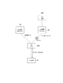
- FIG. 7 is a diagram showing an example of the operation according to the first embodiment.
- another IAB node may intervene between the IAB node (Parent IAB node) 300 and the donor gNB (IAB donor) 200.
- step S101 the user equipment function unit (MT) of the IAB node 300 detects a radio problem (radio problem).
- step S102 the user device function unit (MT) of the IAB node 300 detects the BH RLF (RLF declaration).
- step S103 the user equipment function unit (MT) of the IAB node 300 notifies the base station function unit (DU) of the IAB node 300 of the state information indicating the occurrence of BH RLF.
- step S104 the base station function unit (DU) of the IAB node 300 starts the periodic transmission of the BH RLF Notification in response to the notification from the user device function unit (MT).
- step S105 the lower device B that has received the BH RLF Notification starts a process for switching the connection destination or the communication path from the IAB node 300.
- processing include connection reestablishment processing (Early RRC Re-establishment), conditional handover trigger processing (Triggering Conditional HO), and communication path switching processing (Switching to redundant route).
- step S106 the user device function unit (MT) of the IAB node 300 cannot reestablish the connection during, for example, the operation of the T310, and transitions to the RRC idle state according to the expiration of the T310 (Go to IDLE).
- step S107 the user equipment function unit (MT) of the IAB node 300 notifies the base station function unit (DU) of the IAB node 300 of the state information indicating the transition to the RRC idle state.
- step S108 the base station function unit (DU) of the IAB node 300 stops providing services to the lower device B in response to a notification from the user device function unit (MT) (Service stopped).
- step S109 the lower device B detects the RLF because the service provision from the IAB node 300 is stopped.
- the IAB node 300 that has detected the BH RLF transmits the BH RLF Notification to the lower device B, and the lower device B receives the BH RLF Notification.
- An example of starting the process for switching the connection destination or the communication path from the IAB node 300 has been described.
- the lower device B stops the uplink transmission to the IAB node 300 in response to the reception of the BH RLF Notification from the IAB node 300.
- the uplink signal of the lower device B is sent to the donor device 200. Not reachable. Therefore, the lower device B stops the uplink transmission in response to the reception of the BH RLF Notification from the IAB node 300, so that the increase in power consumption and interference can be suppressed.
- the communication control method according to this modification is a communication control method used in the mobile communication system 1 capable of forming at least one communication path using a plurality of IAB nodes 300 between the UE 100 and the donor device 200.
- the IAB node 300 included in the plurality of IAB nodes 300 detects the BH RLF (BH RLF) between the higher-level device A of the IAB node 300 and the IAB node 300.
- the IAB node 300 transmits a failure notification (BH RLF Notification) regarding the BH RLF to the lower device B lower than the IAB node 300.
- the lower device B has the function of stopping the uplink transmission to the IAB node 300 in response to the reception of the BH RLF Notification from the IAB node 300.
- the lower device B may stop the uplink transmission to the IAB node 300 and start the process for switching the connection destination or the communication path from the IAB node 300. Alternatively, the lower device B waits for the restoration of the BH RLF in a state where the uplink transmission to the IAB node 300 is stopped, and if the BH RLF does not recover even after waiting for a certain period of time, the connection destination or the communication path is switched from the IAB node 300. You may start the process of.
- the suspension of uplink transmission in the lower device B includes at least one of the following a) to e).
- a scheduling request is a signal requesting allocation of uplink radio resources.
- the subordinate device B that has received the BH RLF Notification from the IAB node 300 stops (prohibits) the transmission of the scheduling transmission to the IAB node 300.
- PUSCH Physical Uplink Shared Channel
- the subordinate device B that has received the BH RLF Notification from the IAB node 300 has this allocation even when the uplink radio resource (PUSCH resource) is allocated from the IAB node 300, that is, even if it receives the uplink grant. Stops (prohibits) PUSCH transmission without applying. That is, the lower device B that has received the BH RLF Notification from the IAB node 300 stops (prohibits) the transmission of the uplink data and the uplink RRC signaling.
- PUSCH resource Physical Uplink Shared Channel
- Suspend the radio bearer of lower device B Suspend the wireless bearer means to stop (prohibit) the use of the wireless bearer while maintaining the wireless bearer settings.
- the subordinate device B that has received the BH RLF Notification from the IAB node 300 may suspend all the radio bearers corresponding to the IAB node 300, or data among these radio bearers while continuing to use the signaling radio bearer. You may suspend the wireless bearer.
- Stop PUCCH transmission from the lower device B to the IAB node 300 This may include the suspension of SR transmission by the MAC layer described in a) and the suspension of CSI (Channel State Information) feedback by the PHY layer.
- the lower device B may determine that the IAB node 300 has recovered from the BH RLF, and restart the uplink transmission according to this determination.
- the IAB node 300 transmits a notification (RLF Recovered) indicating that the BH RLF has been restored to the lower device B
- the lower device B receives the RLF Recovered
- the IAB node 300 receives the BH RLF. It is judged that it has recovered from, and the uplink transmission is restarted.
- the lower device B responds to the stoppage of the transmission of the BH RLF Notification. Then, it is determined that the IAB node 300 has recovered from the BH RLF, and the uplink transmission is restarted.
- the lower device B may determine that the transmission of the BH RLF Notification has stopped when the BH RLF Notification has not been received. For example, when the BH RLF Notification is not received at a predetermined timing, the determination is performed.
- the predetermined timing may be the transmission cycle in the case of the periodic transmission.
- the BH RLF Notification transmission stop is, for example, when the lower device B has already stopped when the scheduling request is desired to be transmitted, or at the next BH RLF Notification timing from the time when the scheduling request is desired to be transmitted. This includes the case where BH RLF Notification has stopped.
- FIG. 8 is a diagram showing a configuration when a dual connection is applied in this modified example.
- the lower device B performs dual connection communication in which the IAB node 300M is the master node (MN) and the IAB node 300S is the secondary node (SN).
- MN master node
- SN secondary node
- MCG master cell group
- SCG secondary cell group
- the higher-level device A1 of the IAB node 300M and the higher-level device A2 of the IAB node 300S are the IAB node 300 or the gNB 200.
- the lower device B is an IAB node 300 or a UE 100.
- the IAB node 300M which is an MN
- the IAB node 300M detects the BH RLF with the upper device A1
- the lower device B stops the uplink transmission to the IAB node 300M and stops the uplink transmission to the SN IAB node 300S in response to the reception of the BH RLF Notification from the MN IAB node 300M.
- the MN detects the BH RLF
- the lower device B stops all uplink transmissions (uplink transmissions to MCG and SCG).
- the IAB node 300S which is an SN
- the IAB node 300S detects the BH RLF with the upper device A2
- the lower device B stops the uplink transmission to the IAB node 300S which is the SN without stopping the uplink transmission to the IAB node 300M which is the MN.
- the SN detects the BH RLF
- the lower device B stops only the uplink transmission to the SN (uplink transmission to the SCG).
- the IAB node 300 transmits the BH RLF Notification in the MAC layer.
- the lower device B that has received such BH RLF Notification notifies the upper layer about the BH RLF Notification received in the MAC layer.
- the communication control method according to this modification is a communication control method used in the mobile communication system 1 capable of forming at least one communication path using a plurality of IAB nodes 300 between the UE 100 and the donor device 200.
- the IAB node 300 included in the plurality of IAB nodes 300 detects the BH RLF between the higher-level device A of the IAB node 300 and the IAB node 300.
- the MAC layer of the IAB node 300 transmits a failure notification (BH RLF Notification) regarding the BH RLF to the lower device B lower than the IAB node 300.
- the MAC layer of the lower device B notifies the upper layer of the lower device B that the failure notification has been received in response to the reception of the failure notification from the IAB node 300.
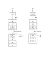
- FIG. 9 is a diagram showing an operation related to this modified example.
- FIG. 9 (1) shows an example in which the lower device B is the IAB node 300.
- FIG. 9 (2) shows an example in which the lower device B is the UE 100.
- the host device A may be an IAB node 300 or a gNB 200 (donor device).
- the IAB node 300 has an MT, a BAP layer, and a DU. At least a part of the BAP layer may be contained in MT or DU.
- the DU of the IAB node 300 has a MAC layer.
- the DU also has a PHY layer and an RLC layer (not shown).
- the MT of the lower device B (lower IAB node) has a MAC layer and an RRC layer.
- the DU also has a PHY layer and an RLC layer (not shown).
- the IAB node 300 is configured in the same manner as in FIG. 9 (1).
- the lower device B (UE100) has a MAC layer, a PDCP layer, and an RRC layer.
- the UE 100 also has a PHY layer and an RLC layer (not shown).
- the MAC layer of the DU of the IAB node 300 transmits the BH RLF Notification to the lower device B in response to the detection of the BH RLF. .. BH RLF Notification may be included in MAC CE (Control Element).
- the MAC layer of the lower device B receives the BH RLF Notification, it notifies the upper layer of the lower device B that the BH RLF Notification has been received.
- the notification to the upper layer may be a notification indicating that BH RLF has been detected in the IAB node 300, or is used by the corresponding communication path (or the wireless link between the IAB node 300 and the lower device B). It may be a notification that it is impossible.
- the upper layer to be notified from the MAC layer includes at least one of the RRC layer, the BAP layer, and the PDCP layer.
- the upper layer may perform the process described in the first embodiment, that is, the process for switching the connection destination or the communication path from the IAB node 300, or as described in the first modification of the first embodiment. Processing, that is, uplink transmission may be stopped.
- the RRC layer that has received the notification from the MAC layer executes, for example, at least one of the following processes.
- the RRC layer establishes a link by an MT other than the MT that has received the BH RLF Notification.
- the RRC layer performs an RRC reestablishment process (RRC Restabrishment) on another cell (another higher-level device).
- the RRC layer transmits a notification (SCG Fairure Indication) to the MN (MCG).
- the RRC layer transmits a notification (MCG Fairure Indication) to the SN (SCG).
- the BAP layer or the PDCP layer that has received the notification from the MAC layer transfers the buffered upstream data to another link (rerouting) when the lower device B has a dual connection.
- the BAP layer or the PDCP layer transfers the upstream data to the MN (MCG).
- MCG MN
- the BAP layer or the PDCP layer transfers the upstream data to the SN (SCG).
- the BAP layer or PDCP layer stops the transmission of upstream data to the RLC channel (that is, the RLC entity) that has established a link with the route (upper node) where the BH RLF is occurring.
- BH RLF Notification may be transmitted / received in, for example, the RRC layer.
- the RRC layer of the lower device B receives the BH RLF Notification, it notifies another layer (for example, the BAP layer and / or the MAC layer) that the BH RLF Notification has been received.
- the BH RLF Notification may be transmitted and received in the BAP layer.
- the BAP layer of the lower device B receives the BH RLF Notification, it notifies another layer (for example, the RRC layer and / or the MAC layer) that the BH RLF Notification has been received.
- the IAB node 300 periodically (continuously) transmits the BH RLF Notification within the period in which the BH RLF is generated will be described.
- the transmission cycle may be a constant cycle defined in the specifications of the mobile communication system 1, but in this modification, the transmission cycle is variable.
- the communication control method according to this modification is a communication control method used in the mobile communication system 1 capable of forming at least one communication path using a plurality of IAB nodes 300 between the UE 100 and the donor device 200.
- the IAB node 300 included in the plurality of IAB nodes 300 detects the BH RLF between the higher-level device A of the IAB node 300 and the IAB node 300.
- the IAB node 300 In response to the detection of the BH RLF, the IAB node 300 repeatedly transmits a failure notification (BH RLF Notification) regarding the BH RLF to the lower device B lower than the IAB node 300.
- the IAB node 300 has a function of transmitting timing information regarding the timing of repeated transmission of the failure notification to the lower device B.
- the transmission cycle of the failure notification (BH RLF Notification) can be made variable. If the cycle is shortened, transmission will occur frequently, so when the upper node recovers from BH RLF, the lower node can quickly know the recovery and can quickly perform recovery operations such as resuming UL transmission. There is a merit that can be done. On the other hand, there are disadvantages that the power consumption required for transmission / reception increases and interference increases. When the cycle is lengthened, the above advantages / disadvantages are reversed. Therefore, the transmission cycle of the failure notification (BH RLF Notification) can be adjusted to the optimum value according to the network design policy.
- the repetitive transmission may be a periodic transmission or an aperiodic transmission.
- the timing information transmitted by the IAB node 300 includes information indicating the transmission cycle of the BH RLF Notification.
- the timing information transmitted by the IAB node 300 may include information indicating a subframe number corresponding to the transmission timing of the BH RLF Notification.
- the IAB node 300 may transmit the SIB including the timing information by broadcasting.
- the donor device may send an RRC message (RRC Configuration message) including timing information to the lower device B via the IAB node 300.
- the IAB node 300 may transmit timing information to the lower device B together with the BH RLF Notification. Specifically, the IAB node 300 transmits BH RLF Notification including timing information.
- the timing information included in one BH RLF Notification may include information indicating a subframe number corresponding to the transmission timing of the next BH RLF Notification.
- the BH RLF Notification may be transmitted and received in the MAC layer.
- the IAB node 300 that has detected the BH RLF may repeatedly transmit the BH RLF Notification to the lower device B during the period of trying to reestablish the backhaul link. Specifically, even if the IAB node 300 that detects the BH RLF fails to reestablish the RRC of the backhaul link, it transmits the BH RLF Notification within the period during which the trial of reestablishing the RRC of the backhaul link is continued. continue. If the RRC reestablishment is not successful within this period, the DU of the IAB node 300 stops the transmission of the BH RLF Notification and also stops the service provision to the lower device B (that is, PSS / SSS / MIB / SIB1). To stop). Further, the MT of the IAB node 300 transitions to the RRC idle state.
- the second embodiment is an embodiment assuming a double connection (DC), and can be used in combination with the operation according to the first embodiment and its modified example.
- DC double connection
- FIG. 10 is a diagram showing an operation example 1 of the second embodiment.
- the IAB node 300 performs dual connection communication in which the host device A1 is the MN and the host device A2 is the secondary node (SN).
- a lower device B is wirelessly connected to the IAB node 300.
- the lower device B is a lower IAB node or UE.
- the IAB node 300 does not set a backhaul link for a communication path with the host device A1 which is an MN, but sets a control link for the host device A1 to control the IAB node 300.
- the IAB node 300 sets a backhaul link for a communication path with the host device A2 which is an SN.
- the IAB node 300 having a dual connection sets both the backhaul link with the MN and the backhaul link with the SN, even if BH RLF occurs in the backhaul link with the SN, the backhaul with the MN As long as the BH RLF is maintained on the hall link, it is considered unnecessary for the IAB node 300 to transmit the BH RLF Notification to the lower device B. This is because even if BH RLF occurs in the backhaul link with the SN, the lower device B may maintain the connection to the IAB node 300 as long as the backhaul link with the MN is maintained.
- the IAB node 300 having a dual connection does not set a backhaul link with the MN, the IAB node 300 cannot send and receive the data of the lower device B to and from the MN. Therefore, when BH RLF occurs in the backhaul link with the SN, the lower device B cannot transmit / receive data via the IAB node 300, so that the IAB node 300 transmits the BH RLF Notification to the lower device B. Should be done.
- the communication control method according to this operation example is a communication control method used in the mobile communication system 1 capable of forming at least one communication path using a plurality of IAB nodes 300 between the UE 100 and the donor device 200.
- the IAB node 300 included in the plurality of IAB nodes 300 performs dual connection communication in which the higher-level device A2 of the IAB node 300 is the SN and the other device (upper device A1) is the MN.
- the higher-level device A2 of the IAB node 300 is the SN and the other device (upper device A1) is the MN.
- the IAB node 300 detects the BH RLF between the IAB node 300 and the SN, and in response to the detection of the BH RLF, the IAB node 300 issues a failure notification (BH RLF Notification) regarding the BH RLF. It has to transmit to the lower device B of the lower 300.
- BH RLF Notification a failure notification regarding the BH RLF. It has to transmit to the lower device B of the lower 300.
- the IAB node 300 that performs dual connection communication transmits a failure notification to the lower device B depending on whether or not a backhaul link is set with the MN. Decide whether or not. Specifically, when the backhaul link is not set between the IAB node 300 and the MN, the IAB node 300 transmits a failure notification to the lower device B in response to the detection of the BH RLF between the IAB node 300 and the SN. Then decide. On the other hand, when a backhaul link is set with the MN, the IAB node 300 determines that the failure notification is not transmitted to the lower device B even if the BH RLF between the IAB node 300 and the SN is detected. To do.
- double connection (DC) by LTE and NR that is, EN-DC (E-UTRA (Evolved Universal Terrestrial Radio Access) -NR Dual Connectivity) may be assumed.
- the MN (upper device A1) is an LTE device
- the SN (upper device A2) is an NR device.
- the MN (upper device A1) is the LTE base station eNB
- the SN (upper device A2) is the NR base station gNB (donor device 200) or the upper IAB node.
- a dual connection (DC) using only NR that is, NR-DC (NR Dual Connectivity) may be assumed.
- the MN (upper device A1) is an NR device
- the SN (upper device A2) is also an NR device.
- the MN (upper device A1) is a gNB or upper IAB node that is an NR base station
- the SN (upper device A2) is a gNB or upper IAB node that is an NR base station.
- the IAB node 300 may receive setting information indicating whether or not it is used as a backhaul link from the donor device 200, and set and identify the backhaul link based on this setting information.
- the setting information may be information indicating whether or not the backhaul link is used for each CG (Cell Group) or each bearer.
- FIG. 11 is a diagram showing an operation example 2 of the second embodiment.
- the lower device B performs dual connection communication in which the upper device A1 is the MN and the IAB node 300 is the secondary node (SN).
- the lower device B is a lower IAB node or UE.
- the IAB node 300 detects the BH RLF with the upper device A2 of the IAB node 300, the IAB node 300 transmits the BH RLF Notification to the lower device B.
- the MN upper device A1
- the host device A1 is an IAB node or a base station
- the host device A2 is an IAB node or a base station (donor device 200).
- the communication control method according to this operation example is a communication control method used in the mobile communication system 1 capable of forming at least one communication path using a plurality of IAB nodes 300 between the UE 100 and the donor device 200.
- the lower device B below the IAB node 300 performs dual connection communication with the IAB node 300 as the SN and the other device (upper device A1) as the MN.
- the IAB node 300 detects the BH RLF between the upper device (upper device A2) of the IAB node 300 and the IAB node 300, the first failure notification (BH RLF Notification) is transmitted to the lower device B.
- the lower device B has a function of transmitting a second failure notification (Failure Indication) indicating BH RLF in the SN to the MN in response to the reception of the first failure notification from the IAB node 300 which is the SN.
- a second failure notification (Failure Indication) indicating BH RLF in the SN to the MN in response to the reception of the first failure notification from the IAB node 300 which is the SN.
- the lower device B When the lower device B detects the RLF between the lower device B and the IAB node 300, the lower device B may transmit the SCG Failure Indication to the MN.
- the second failure notification (Failure Indication) is when BH RLF occurs between the IAB node 300 and the upper device A2 even if the RLF is not detected between the lower device B and the IAB node 300. Is transmitted from the lower device B to the MN.
- the second failure notification (Failure Indication) may be an information element in the SCG Failure Indication message, or may be a message different from the SCG Failure Indication message.
- the lower device B may include "BH RLF" in the second failure notification (Failure Indication) as information indicating the cause (Cause) of the SCG failure.
- the second failure notification may include an identifier indicating the IAB node 300 or its cell.
- the higher-level device A1 (MN) that has received the second failure notification (Failure Indication) from the lower-level device B changes the SN (Secondary Node Change) in order to connect the link on the IAB node 300 side, which is the SN, to another higher-level device. Etc. are performed. Further, the host device A1 (MN) determines that the DC setting has been disconnected (filed) based on the second failure notification (Failure Indication), and executes a process of releasing the UE context in the SN IAB node 300. You may. For example, a UE context release message is transmitted from the host device A1 (MN) to the IAB node 300 (SN) via the interface between the host device A1 (MN) and the IAB node 300 (SN).
- SN Service Node Change
- FIG. 12 is a diagram showing an operation example 3 of the second embodiment.
- the IAB node 300 is performing dual connection communication with the MN300M and the SN300S.
- Each of the MN300M and SN300S is an upper IAB node.
- the MN300M detects the BH RLF with its higher-level device A1, it transmits the BH RLF Notification to the IAB node 300.
- the SN300S detects the BH RLF with its own higher-level device A2, the SN300S transmits the BH RLF Notification to the IAB node 300.
- Each of the higher-level devices A1 and A2 is a higher-level IAB node or base station.
- RLF is not generated in the MCG link which is the link between the IAB node 300 and the MN300M
- RLF is not generated in the SCG link which is the link between the IAB node 300 and the SN300S. ..
- the IAB node 300 transmits the BH RLF Notification to the lower device B only when the BH RLF Notification is received from both the MN300M and the SN300S. In other words, when the IAB node 300 receives the BH RLF Notification from only one of the MN300M and the SN300S, the IAB node 300 does not transmit the BH RLF Notification to the lower device B.
- the communication control method according to this operation example is a communication control method used in the mobile communication system 1 capable of forming at least one communication path using a plurality of IAB nodes 300 between the UE 100 and the donor device 200.
- the IAB node 300 included in the plurality of IAB nodes 300 performs dual connection communication with the MN300M and the SN300S.
- the MN300M detects the BH RLF between the higher-level device A1 of the MN300M and the MN300M, it transmits a first failure notification (BH RLF Notification) to the IAB node 300.
- the SN300S When the SN300S detects the BH RLF between the higher device A2 of the SN300S and the SN300S, it transmits a second failure notification (BH RLF Notification) to the IAB node 300. 4) When the IAB node 300 receives both the first failure notification and the second failure notification, the third failure notification (BH RLF Notification) is transmitted to the lower device B lower than the IAB node 300, and Has.
- the IAB node 300 receives both the first failure notification and the second failure notification even if RLF does not occur between the IAB node 300 and the MN300M and between the IAB node 300 and the SN300S.
- the IAB node 300 notifies the lower device B of the third failure (BH RLF Notification) when BH RLF is detected in both the MN300M and the SN300S even if the wireless state of the IAB node 300 is good.
- BH RLF Notification the third failure notification
- the IAB node 300 When the IAB node 300 receives both the first failure notification and the second failure notification, it may be considered that the BH RLF at the IAB node 300 has occurred.
- the IAB node 300 considers that the BH RLF has occurred, and as a result, transmits the BH RLF Notification to the lower device B. Further, the IAB node 300 may perform an operation such as reestablishing the RRC for another higher-level device by regarding that the BH RLF has occurred.
- the lower device A third failure notification may be sent to B. That is, the IAB node 300 does not receive both the first failure notification and the second failure notification and immediately transmits the third failure notification to the lower device B, but sends both the first failure notification and the second failure notification. After confirming that its own backhaul communication is not restored within a certain period of time after receiving it, the third failure notification is transmitted to the lower device B.
- the IAB node 300 determines that its backhaul communication has been restored within a certain period of time after receiving both the first failure notification and the second failure notification, the IAB node 300 notifies the lower device B of the third failure. Do not send.
- FIG. 13 is an operation flow diagram of the IAB node 300 in this operation example.
- each of the MN300M and the SN300S periodically (continuously) transmits the BH RLF Notification within the period during which the BH RLF is detected.
- step S201 the IAB node 300 determines whether or not BH RLF Notification has been received from both the MN300M (MCG) and the SN300S (SCG), that is, all the CGs.
- MCG MN300M
- SCG SN300S
- step S202 the IAB node 300 activates a timer corresponding to a certain time.
- the value of this timer may be set in the IAB node 300 by the MN300M or the host device A1 (for example, a donor device).
- step S203 the IAB node 300 determines whether or not reception of BH RLF Notification from both MN300M (MCG) and SN300S (SCG), that is, all CGs is continued. If "No" in step S203, the process returns to step S201.
- MCG MN300M
- SCG SN300S
- step S204 the IAB node 300 determines whether or not the timer started in step S202 has expired. If “No” in step S204, the process returns to step S203.
- step S204 the IAB node 300 transmits the BH RLF Notification to the lower device B in step S205.
- the IAB node 300 may consider that its own BH RLF has occurred in step S205.
- each of the MN300M and the SN300S periodically (continuously) transmits the BH RLF Notification within the period during which the BH RLF is detected.
- each of the MN300M and the SN300S may send a notification (BH Recovered) indicating the recovery when the BH RLF is restored.
- the IAB node 300 may determine whether or not BH Recovered has been received from at least one CG in step S203. Then, when the IAB node 300 receives BH Recovered from at least one CG, the process returns to step S201. On the other hand, if the IAB node 300 has not received BH Recovered from any of the CGs, the process proceeds to step S204.
- the case where "No" is determined in step S203 of FIG. 13 includes a case where the IAB node 300 succeeds in reestablishing the RRC for another higher-level device after receiving the BH RLF Notification from both CGs. ..
- FIG. 14 is a diagram showing an operation example 4 of the second embodiment.
- the lower device B is performing dual connection (NR-DC) communication with the MN300M and the SN300S.
- the lower device B is an IAB node or UE.
- Each of the MN300M and SN300S is an IAB node.
- a backhaul link is set between the MN300M and the host device A1, and a backhaul link is set between the SN300S and the host device A2.
- the communication control method according to this operation example is a communication control method used in the mobile communication system 1 capable of forming at least one communication path using a plurality of IAB nodes 300 between the UE 100 and the donor device 200.
- the lower device B performs dual connection communication with the MN300M and the SN300S included in the plurality of IAB nodes 300
- the MN300M detects the BH RLF between the upper device A1 and the MN300M
- the MN300M sends a first failure notification (BH RLF Notification) to the lower device B.
- the MN300M detects the BH RLF between the upper device A2 of the SN300S and the SN300S
- the MN300M transmits a second failure notification (BH RLF Notification) to the lower device B.
- the SN300S transmits information about the BH RLF of the SN300S from the SN300S to the MN300M using the interface between the MN300M and the SN300S.
- the host device A2 of the SN300S can detect the BH RLF of the SN300S
- the information about the BH RLF of the SN300S may be transmitted from the host device A2 to the MN300M via the donor device 200.
- the first failure notification includes information indicating the occurrence of BH RLF of the MN300M
- the second failure notification includes information indicating the occurrence of BH RLF of the SN300S.
- the SN300S specifies whether or not the MN300M has a backhaul link based on the notification from the donor device 200 (CU) or the notification from the MN300M.
- the SN300S prohibits the transmission of the BH RLF Notification from the SN300S to the lower device B when the MN300M has a backhaul link.
- the SN300S enables transmission of BH RLF Notification from the SN300S to the lower device B when the MN300M does not have a backhaul link.
- FIG. 15 is a diagram showing an operation example 5 of the second embodiment.
- the lower device B is performing dual connection communication with the MN300M and the SN300S.
- Each of the MN300M and SN300S is an IAB node.
- a backhaul link is set between the MN300M and the host device A1, and a backhaul link is set between the SN300S and the host device A2.
- the lower device B receives a message addressed to the SN300S from the MN300M and transfers the received message to the SN300S.
- the message addressed to the SN300S is, for example, a message for the inter-base station interface (Xn interface) or a message for the CU-DU interface (F1 interface), and is a release message for releasing the SN300S.
- the communication control method according to this operation example is a communication control method used in the mobile communication system 1 capable of forming at least one communication path using a plurality of IAB nodes 300 between the UE 100 and the donor device 200.
- the lower device B performs dual connection communication with the MN300M and the SN300S included in the plurality of IAB nodes 300, and 2) After the SN300S detects the BH RLF between the upper device A2 and the SN300S, the lower device B receives a message addressed to the SN300S from the MN300M. 3) The lower device B has the function of transferring the message received from the MN300M to the SN300S.
- the BH RLF of the SN300S is detected, and the SN300S can receive the message from the MN300M even when the interface does not exist between the MN300M and the SN300S.
- This operation example includes the following procedure.
- the lower device B receives the BH RLF Notification indicating the BH RLF of the SN300S from the SN300S.
- the lower device B may receive the BH RLF Notification indicating the BH RLF of the SN300S from the MN300M (see operation example 4).
- the lower device B may transmit the Failure Indication to the MN300M (see operation example 2).
- the MN300M or the donor device 200 instructs the lower device B to relay the network interface (Xn / F1, etc.).
- the MN300M or the donor device 200 may set exception routing in the routing table information of the lower device B. This setting includes either the ID of the SN300S or its cell and the ID of an entity in the BAP layer of the SN300S.
- the lower device B may notify the SN300S that the exception routing via the lower device B has been set, or request the exception routing via the lower device B.
- the lower device B may notify (respond) to the MN300M or the donor device 200 whether or not a relay route via the lower device B has been established. In the case of notification that the relay route cannot be established (NG), information such as rejection of the SN300S and rejection of the lower device B may be included in the notification as information indicating the cause.
- NG relay route cannot be established
- the MN300M or the donor device 200 transmits a network interface message (for example, a Secondary Node Release message) to the relay route.
- a network interface message for example, a Secondary Node Release message
- the message is encapsulated and carried, for example, by an RRC message or a BAP control message.
- the lower device B forwards the encapsulated message to the SN300S according to the exception routing information described above.
- the SN300S receives the encapsulated message and performs an operation according to the received message. For example, the SN300S performs processing such as stopping the use of wireless resources when receiving Secondary Node Release.
- the SN300S may return the Secondary Node Release Acknowledge to the MN300M or the donor device 200 via the lower device B using exception routing.
- the base station in the mobile communication system 1 may be an eNB which is an LTE base station.
- the core network in the mobile communication system 1 may be an EPC (Evolved Packet Core).
- the gNB may be connected to the EPC
- the eNB may be connected to the 5GC
- the gNB and the eNB may be connected via the inter-base station interface (Xn interface, X2 interface).
- a program for causing a computer to execute each process related to each of the above-described embodiments and modifications thereof may be provided.
- the program may also be recorded on a computer-readable medium.
- Computer-readable media can be used to install programs on a computer.
- the computer-readable medium on which the program is recorded may be a non-transient recording medium.
- the non-transient recording medium is not particularly limited, but may be, for example, a recording medium such as a CD-ROM or a DVD-ROM.
- a chipset composed of a memory for storing a program for executing each process performed by the UE 100, the gNB 200, or the IAB node 300 and a processor for executing the program stored in the memory may be provided.
- RAN2 discussed the details of RLF notifications, including RLF notifications for downstream nodes and RLF notifications for upstream nodes.
- the Rel-15 UE is still allowed to connect with the IAB node, but the agreed "RLF notification" is a Rel-16 feature.
- the IAB node should stop transmitting SSBs (PSS, SSS, and PBCH) if it fails to restore the backhaul link. This is because it is clear that the IAB node cannot continue service without a backhaul link and intentionally creates radio problems for the Rel-15 UE.
- Proposal 1 RAN2 should agree that the IAB node will stop sending SSB if it fails to restore the backhaul link.
- Proposal 1 also implies that the IAB node may continue to provide services until the backhaul link fails to recover. Then, downstream MT / for backhaul link status, such as "For example, when the link is restored or is in progress, further consideration is needed to determine if other indications are needed.” Further consideration should be given to whether it is worth notifying the UE. However, if the RLF notification is repeatedly transmitted during BH RLF, it is not necessary to specify "other indications". In other words, if the RLF notification is not sent, the BH RLF has not occurred or has already been recovered, otherwise the backhaul link recovery is in progress. Therefore, the issue is whether to repeatedly transmit the RLF notification during the BH RLF.
- Proposal 2 RAN2 should agree that RLF notifications are repeatedly transmitted during BH RLF.
- Proposal 3 RAN2 should agree that the MT / UE will stop the uplink signal, i.e. the SR for data transmission, upon receiving the RLF notification.
- the parent IAB node When the parent IAB node receives RLF on its backhaul link, an RLF notification is sent, but the access link may still be good. In other words, RLF does not occur on the link between the parent IAB node and the child IAB node. Since RAN2 agrees that "the current UE RLF detection and recovery is reused as a baseline", the child node / UE does not declare an RLF, in which case it does not trigger an RLF notification.
- an RLF notification if the receipt of an RLF notification triggers an existing RLF, it also triggers the transmission of an RLF notification to a downstream node, which is immediately propagated between IAB topologies. This can cause all IAB nodes to initiate RRC re-establishment at the same time, breaking the IAB topology. Therefore, receiving an RLF notification does not trigger an RRC reestablishment.
- Proposal 4 RAN2 should agree that the MT / UE does not declare an RLF containing the start of RRC reestablishment upon receipt of the RLF notification and does not trigger the transmission of the RLF notification either.
- RRC idol Another aspect is MT / UE behavior at RRC idle. If Proposal 3 agrees, it is very easy to refrain from initiating an RRC setup request to the parent IAB node that receives the BH RLF from the MT / UE in idle mode. This can be regarded as a kind of access control. Even if an RRC setup request message is sent, it cannot be forwarded to the IAB donor (ie, the CU with the peer RRC entity) for BH RLF and the procedure will eventually fail.
- IAB donor ie, the CU with the peer RRC entity
- Proposal 5 RAN2 should agree that the RRC idle MT / UE should refrain from initiating an RRC setup request to the parent IAB node sending the RLF notification.
- the issue is how the cell reselection process handles the BH RLF, that is, whether the parent IAB node that sends the BH RLF is a candidate cell for reselection. If BH RLF can be recovered in a short time, such optimization is not necessary. Otherwise, the MT / UE will eventually be unable to establish an RRC connection in the cell without the BH link, which can lead to a bad user experience.
- Proposal 6 RAN2 should discuss whether the RRC idle MT / UE can reselect the parent IAB node to send RLF notifications.
- Case 1 (parent is set by DC)
- the RLF notification may be triggered by either MCG RLF or SCG RLF.
- EN-DC ie, the C plane is on LTE Uu
- RN2 is "For IAB nodes using EN-DC, this is a single link deployment (in terms of BAP and backhaul RLC channels). It is not envisioned to use MCG for backhaul links, as agreed to "only BAP routes via NR links). Therefore, even if the RLF occurs only on the SCG link, it should be considered as a BH RLF from the point of view of the IAB topology. This also means that RLF notifications should be sent by the parent IAB node at SCG RLF.
- Finding 2 In the case of an IAB node configured with EN-DC, the SCG RLF should trigger an RLF notification.
- the backhaul link may be set to SCG only or both SCG and MCG.
- SCG-only BH SCG-only BH
- EN-DC EN-DC
- the UE stops UL transmission to the SCG at the MCG RLF ("suspends all RBs except SRB0" by reestablishing the RRC). As a result, it can be regarded as BH RLF.
- MCG RLF suspends all RBs except SRB0
- the current principles of stopping UL transmission may need to be revisited, depending on whether the SCG link should be used in the event of a failure of the MCG link. For example, the high-speed MCG link recovery mechanism discussed at DCCA WI.
- Finding 3 In the case of an IAB node that is set by NR-DC and has BH only in SCG, SCG RLF triggers RLF notification (similar to finding 2).
- Proposal 7 RAN2 should agree that the SCG RLF triggers an RLF notification if the backhaul link consists of SCG only (ie EN-DC and NR-DC with SCG only backhaul). Is.
- Proposal 8 RAN2 should agree that MCG RLF always triggers RLF notifications.
- Finding 4 If the SCG link is used during MCG RLF, it may be necessary to reconsider the current principles regarding the suspension of UL transmission. It is expected to discuss the high-speed restoration of MCG links in DCCA WI.
- the MCG transmits the RLF notification only on the BH RLF
- the SCG transmits the RLF notification only on the BH RLF. This is easy if MAC CE is used for RLF notifications, as each CG has two separate MACs under dual connectivity.
- Proposal 9 RAN2 should agree that RLF notifications may be transmitted by either MCG or SCG via MAC CE.
- the child IAB node when the child IAB node receives the RLF notification from the SCG, if the proposal 3 is accepted, the UL transmission to the SCG is stopped. This can actually be considered a kind of SCG failure, and the child IAB node may expect the MCG to make a topology match (eg, change the secondary node). However, depending on the IAB topology, if the SCG's BH link fails, the MCG may not be aware that the SCG's BH link is (at least temporarily) disconnected and should take appropriate action. May not be possible. Therefore, it should be considered whether the child node can notify the MCG when it receives the RLF notification from the SCG, for example, via the failure information or the SCG failure information.
- Proposal 10 RAN2 should discuss whether MT / UE is allowed to notify MCG when it receives an RLF notification from SCG.
Landscapes
- Engineering & Computer Science (AREA)
- Computer Networks & Wireless Communication (AREA)
- Signal Processing (AREA)
- Mobile Radio Communication Systems (AREA)
Priority Applications (4)
| Application Number | Priority Date | Filing Date | Title |
|---|---|---|---|
| JP2021537700A JP7301976B2 (ja) | 2019-08-08 | 2020-07-22 | 通信制御方法 |
| US17/666,068 US12219375B2 (en) | 2019-08-08 | 2022-02-07 | Communication control method |
| JP2023101502A JP7667205B2 (ja) | 2019-08-08 | 2023-06-21 | 通信制御方法、第1中継装置、プロセッサ、プログラム、及び移動通信システム |
| US19/007,086 US20250159510A1 (en) | 2019-08-08 | 2024-12-31 | Communication control method |
Applications Claiming Priority (2)
| Application Number | Priority Date | Filing Date | Title |
|---|---|---|---|
| US201962884268P | 2019-08-08 | 2019-08-08 | |
| US62/884,268 | 2019-08-08 |
Related Child Applications (1)
| Application Number | Title | Priority Date | Filing Date |
|---|---|---|---|
| US17/666,068 Continuation US12219375B2 (en) | 2019-08-08 | 2022-02-07 | Communication control method |
Publications (1)
| Publication Number | Publication Date |
|---|---|
| WO2021024821A1 true WO2021024821A1 (ja) | 2021-02-11 |
Family
ID=74503566
Family Applications (1)
| Application Number | Title | Priority Date | Filing Date |
|---|---|---|---|
| PCT/JP2020/028571 Ceased WO2021024821A1 (ja) | 2019-08-08 | 2020-07-22 | 通信制御方法 |
Country Status (3)
| Country | Link |
|---|---|
| US (2) | US12219375B2 (https=) |
| JP (2) | JP7301976B2 (https=) |
| WO (1) | WO2021024821A1 (https=) |
Cited By (3)
| Publication number | Priority date | Publication date | Assignee | Title |
|---|---|---|---|---|
| CN115606243A (zh) * | 2021-04-01 | 2023-01-13 | 苹果公司(Us) | 集成接入和回程无线电链路切换 |
| WO2023026681A1 (ja) * | 2021-08-24 | 2023-03-02 | キヤノン株式会社 | 中継装置、制御方法、プログラム、及び通信システム |
| WO2023141896A1 (en) | 2022-01-27 | 2023-08-03 | Zte Corporation | A method of status information indication for network nodes |
Families Citing this family (4)
| Publication number | Priority date | Publication date | Assignee | Title |
|---|---|---|---|---|
| EP4120789A4 (en) * | 2020-03-27 | 2023-08-02 | Samsung Electronics Co., Ltd. | DEVICE AND METHOD FOR RECOVERY AFTER A FAILURE OF A MASTER CELL GROUP IN A COMBINED ACCESS AND BACKHAUL SYSTEM |
| US20230142688A1 (en) * | 2020-04-17 | 2023-05-11 | Lenovo (Beijing) Ltd. | Method and apparatus of enhanced re-establishment initialization in a communication system |
| WO2022234516A1 (en) * | 2021-05-06 | 2022-11-10 | Nokia Technologies Oy | Coordinating mro analysis for pscell change failure |
| US12133216B2 (en) * | 2021-05-13 | 2024-10-29 | Qualcomm Incorporated | Conditional grants in integrated access and backhaul (IAB) network |
Family Cites Families (6)
| Publication number | Priority date | Publication date | Assignee | Title |
|---|---|---|---|---|
| US11700565B2 (en) * | 2018-09-18 | 2023-07-11 | Qualcomm Incorporated | Management of radio link failure in wireless backhaul |
| WO2020165278A1 (en) * | 2019-02-13 | 2020-08-20 | Telefonaktiebolaget Lm Ericsson (Publ) | Using alternative paths of descendant nodes for backhaul-link failure reporting in integrated access |
| US12193094B2 (en) * | 2019-02-14 | 2025-01-07 | Lg Electronics Inc. | Method and apparatus for failure notification on backhaul link in wireless communication system |
| CN111757398B (zh) * | 2019-03-28 | 2022-04-12 | 华为技术有限公司 | 一种通信方法与装置 |
| WO2020222309A1 (en) * | 2019-05-02 | 2020-11-05 | Sharp Kabushiki Kaisha | Failure information for wireless relay networks |
| KR20230074583A (ko) | 2020-09-30 | 2023-05-30 | 후아웨이 테크놀러지 컴퍼니 리미티드 | 통신 방법 및 관련 디바이스 |
-
2020
- 2020-07-22 WO PCT/JP2020/028571 patent/WO2021024821A1/ja not_active Ceased
- 2020-07-22 JP JP2021537700A patent/JP7301976B2/ja active Active
-
2022
- 2022-02-07 US US17/666,068 patent/US12219375B2/en active Active
-
2023
- 2023-06-21 JP JP2023101502A patent/JP7667205B2/ja active Active
-
2024
- 2024-12-31 US US19/007,086 patent/US20250159510A1/en active Pending
Non-Patent Citations (3)
| Title |
|---|
| CATT: "Route Adaptation upon Backhaul RLF", 3GPP TSG RAN WG2 #106 R2-1905837, 3 May 2019 (2019-05-03), XP051710189 * |
| HUAWEI ET AL.: "Backhaul RLF Recovery", 3GPP TSG RAN WG2 #106 R2-1906070, 3 May 2019 (2019-05-03), XP051710397 * |
| SAMSUNG: "RLF handling in dual connection for intermediate IAB node", 3GPP TSG RAN WG2 #106 R2-1908025, 3 May 2019 (2019-05-03), XP051712273 * |
Cited By (10)
| Publication number | Priority date | Publication date | Assignee | Title |
|---|---|---|---|---|
| CN115606243A (zh) * | 2021-04-01 | 2023-01-13 | 苹果公司(Us) | 集成接入和回程无线电链路切换 |
| WO2023026681A1 (ja) * | 2021-08-24 | 2023-03-02 | キヤノン株式会社 | 中継装置、制御方法、プログラム、及び通信システム |
| JP2023031140A (ja) * | 2021-08-24 | 2023-03-08 | キヤノン株式会社 | 中継装置、制御方法、およびプログラム |
| JP7807885B2 (ja) | 2021-08-24 | 2026-01-28 | キヤノン株式会社 | 中継装置、制御方法、およびプログラム |
| WO2023141896A1 (en) | 2022-01-27 | 2023-08-03 | Zte Corporation | A method of status information indication for network nodes |
| CN118714593A (zh) * | 2022-01-27 | 2024-09-27 | 中兴通讯股份有限公司 | 一种用于网络节点的状态信息指示的方法 |
| EP4356685A4 (en) * | 2022-01-27 | 2024-11-13 | ZTE Corporation | METHOD FOR INDICATING STATUS INFORMATION FOR NETWORK NODES |
| JP2024543767A (ja) * | 2022-01-27 | 2024-11-26 | 中興通訊股▲ふん▼有限公司 | ネットワークノードのための状態情報指示の方法 |
| CN118714593B (zh) * | 2022-01-27 | 2025-12-16 | 中兴通讯股份有限公司 | 一种用于网络节点的状态信息指示的方法 |
| JP7817374B2 (ja) | 2022-01-27 | 2026-02-18 | 中興通訊股▲ふん▼有限公司 | ネットワークノードのための状態情報指示の方法 |
Also Published As
| Publication number | Publication date |
|---|---|
| US20220159485A1 (en) | 2022-05-19 |
| JPWO2021024821A1 (https=) | 2021-02-11 |
| JP2023120360A (ja) | 2023-08-29 |
| JP7667205B2 (ja) | 2025-04-22 |
| JP7301976B2 (ja) | 2023-07-03 |
| US20250159510A1 (en) | 2025-05-15 |
| US12219375B2 (en) | 2025-02-04 |
Similar Documents
| Publication | Publication Date | Title |
|---|---|---|
| US12213199B2 (en) | Relay apparatus | |
| JP7413316B2 (ja) | 中継装置 | |
| JP7560615B2 (ja) | 通信制御方法、第1中継装置及びプロセッサ | |
| JP7667205B2 (ja) | 通信制御方法、第1中継装置、プロセッサ、プログラム、及び移動通信システム | |
| JP7291763B2 (ja) | 通信制御方法 | |
| JP7212199B2 (ja) | 通信制御方法 | |
| JP7422916B2 (ja) | 通信制御方法、無線中継装置及びプロセッサ | |
| JP7052146B2 (ja) | 通信制御方法 | |
| EP3829220A1 (en) | Radio link management for a connected user equipment | |
| JP7522797B2 (ja) | 通信制御方法 | |
| JP7495491B2 (ja) | 通信制御方法及び通信装置 | |
| WO2020032129A1 (ja) | 中継装置 | |
| WO2023282251A1 (ja) | 通信制御方法 | |
| US20220264400A1 (en) | Communication control method and wireless relay apparatus | |
| WO2022210546A1 (ja) | 通信制御方法 | |
| JP7426383B2 (ja) | 通信制御方法 | |
| WO2020158253A1 (ja) | 中継装置及びその制御方法 |
Legal Events
| Date | Code | Title | Description |
|---|---|---|---|
| 121 | Ep: the epo has been informed by wipo that ep was designated in this application |
Ref document number: 20849412 Country of ref document: EP Kind code of ref document: A1 |
|
| ENP | Entry into the national phase |
Ref document number: 2021537700 Country of ref document: JP Kind code of ref document: A |
|
| NENP | Non-entry into the national phase |
Ref country code: DE |
|
| 122 | Ep: pct application non-entry in european phase |
Ref document number: 20849412 Country of ref document: EP Kind code of ref document: A1 |