WO2021024771A1 - Power supply device, electric vehicle using same, and power storage device - Google Patents
Power supply device, electric vehicle using same, and power storage device Download PDFInfo
- Publication number
- WO2021024771A1 WO2021024771A1 PCT/JP2020/028023 JP2020028023W WO2021024771A1 WO 2021024771 A1 WO2021024771 A1 WO 2021024771A1 JP 2020028023 W JP2020028023 W JP 2020028023W WO 2021024771 A1 WO2021024771 A1 WO 2021024771A1
- Authority
- WO
- WIPO (PCT)
- Prior art keywords
- power supply
- supply device
- battery
- cover portion
- power
- Prior art date
Links
Images


Classifications
-
- H—ELECTRICITY
- H01—ELECTRIC ELEMENTS
- H01M—PROCESSES OR MEANS, e.g. BATTERIES, FOR THE DIRECT CONVERSION OF CHEMICAL ENERGY INTO ELECTRICAL ENERGY
- H01M50/00—Constructional details or processes of manufacture of the non-active parts of electrochemical cells other than fuel cells, e.g. hybrid cells
- H01M50/20—Mountings; Secondary casings or frames; Racks, modules or packs; Suspension devices; Shock absorbers; Transport or carrying devices; Holders
- H01M50/271—Lids or covers for the racks or secondary casings
- H01M50/273—Lids or covers for the racks or secondary casings characterised by the material
- H01M50/282—Lids or covers for the racks or secondary casings characterised by the material having a layered structure
-
- B—PERFORMING OPERATIONS; TRANSPORTING
- B60—VEHICLES IN GENERAL
- B60L—PROPULSION OF ELECTRICALLY-PROPELLED VEHICLES; SUPPLYING ELECTRIC POWER FOR AUXILIARY EQUIPMENT OF ELECTRICALLY-PROPELLED VEHICLES; ELECTRODYNAMIC BRAKE SYSTEMS FOR VEHICLES IN GENERAL; MAGNETIC SUSPENSION OR LEVITATION FOR VEHICLES; MONITORING OPERATING VARIABLES OF ELECTRICALLY-PROPELLED VEHICLES; ELECTRIC SAFETY DEVICES FOR ELECTRICALLY-PROPELLED VEHICLES
- B60L50/00—Electric propulsion with power supplied within the vehicle
- B60L50/50—Electric propulsion with power supplied within the vehicle using propulsion power supplied by batteries or fuel cells
- B60L50/60—Electric propulsion with power supplied within the vehicle using propulsion power supplied by batteries or fuel cells using power supplied by batteries
- B60L50/64—Constructional details of batteries specially adapted for electric vehicles
-
- B—PERFORMING OPERATIONS; TRANSPORTING
- B60—VEHICLES IN GENERAL
- B60L—PROPULSION OF ELECTRICALLY-PROPELLED VEHICLES; SUPPLYING ELECTRIC POWER FOR AUXILIARY EQUIPMENT OF ELECTRICALLY-PROPELLED VEHICLES; ELECTRODYNAMIC BRAKE SYSTEMS FOR VEHICLES IN GENERAL; MAGNETIC SUSPENSION OR LEVITATION FOR VEHICLES; MONITORING OPERATING VARIABLES OF ELECTRICALLY-PROPELLED VEHICLES; ELECTRIC SAFETY DEVICES FOR ELECTRICALLY-PROPELLED VEHICLES
- B60L3/00—Electric devices on electrically-propelled vehicles for safety purposes; Monitoring operating variables, e.g. speed, deceleration or energy consumption
- B60L3/0023—Detecting, eliminating, remedying or compensating for drive train abnormalities, e.g. failures within the drive train
- B60L3/0046—Detecting, eliminating, remedying or compensating for drive train abnormalities, e.g. failures within the drive train relating to electric energy storage systems, e.g. batteries or capacitors
-
- B—PERFORMING OPERATIONS; TRANSPORTING
- B60—VEHICLES IN GENERAL
- B60L—PROPULSION OF ELECTRICALLY-PROPELLED VEHICLES; SUPPLYING ELECTRIC POWER FOR AUXILIARY EQUIPMENT OF ELECTRICALLY-PROPELLED VEHICLES; ELECTRODYNAMIC BRAKE SYSTEMS FOR VEHICLES IN GENERAL; MAGNETIC SUSPENSION OR LEVITATION FOR VEHICLES; MONITORING OPERATING VARIABLES OF ELECTRICALLY-PROPELLED VEHICLES; ELECTRIC SAFETY DEVICES FOR ELECTRICALLY-PROPELLED VEHICLES
- B60L53/00—Methods of charging batteries, specially adapted for electric vehicles; Charging stations or on-board charging equipment therefor; Exchange of energy storage elements in electric vehicles
- B60L53/60—Monitoring or controlling charging stations
-
- H—ELECTRICITY
- H01—ELECTRIC ELEMENTS
- H01M—PROCESSES OR MEANS, e.g. BATTERIES, FOR THE DIRECT CONVERSION OF CHEMICAL ENERGY INTO ELECTRICAL ENERGY
- H01M10/00—Secondary cells; Manufacture thereof
- H01M10/04—Construction or manufacture in general
- H01M10/0481—Compression means other than compression means for stacks of electrodes and separators
-
- H—ELECTRICITY
- H01—ELECTRIC ELEMENTS
- H01M—PROCESSES OR MEANS, e.g. BATTERIES, FOR THE DIRECT CONVERSION OF CHEMICAL ENERGY INTO ELECTRICAL ENERGY
- H01M10/00—Secondary cells; Manufacture thereof
- H01M10/42—Methods or arrangements for servicing or maintenance of secondary cells or secondary half-cells
- H01M10/425—Structural combination with electronic components, e.g. electronic circuits integrated to the outside of the casing
-
- H—ELECTRICITY
- H01—ELECTRIC ELEMENTS
- H01M—PROCESSES OR MEANS, e.g. BATTERIES, FOR THE DIRECT CONVERSION OF CHEMICAL ENERGY INTO ELECTRICAL ENERGY
- H01M10/00—Secondary cells; Manufacture thereof
- H01M10/42—Methods or arrangements for servicing or maintenance of secondary cells or secondary half-cells
- H01M10/44—Methods for charging or discharging
- H01M10/441—Methods for charging or discharging for several batteries or cells simultaneously or sequentially
-
- H—ELECTRICITY
- H01—ELECTRIC ELEMENTS
- H01M—PROCESSES OR MEANS, e.g. BATTERIES, FOR THE DIRECT CONVERSION OF CHEMICAL ENERGY INTO ELECTRICAL ENERGY
- H01M10/00—Secondary cells; Manufacture thereof
- H01M10/42—Methods or arrangements for servicing or maintenance of secondary cells or secondary half-cells
- H01M10/46—Accumulators structurally combined with charging apparatus
-
- H—ELECTRICITY
- H01—ELECTRIC ELEMENTS
- H01M—PROCESSES OR MEANS, e.g. BATTERIES, FOR THE DIRECT CONVERSION OF CHEMICAL ENERGY INTO ELECTRICAL ENERGY
- H01M10/00—Secondary cells; Manufacture thereof
- H01M10/42—Methods or arrangements for servicing or maintenance of secondary cells or secondary half-cells
- H01M10/48—Accumulators combined with arrangements for measuring, testing or indicating the condition of cells, e.g. the level or density of the electrolyte
- H01M10/482—Accumulators combined with arrangements for measuring, testing or indicating the condition of cells, e.g. the level or density of the electrolyte for several batteries or cells simultaneously or sequentially
-
- H—ELECTRICITY
- H01—ELECTRIC ELEMENTS
- H01M—PROCESSES OR MEANS, e.g. BATTERIES, FOR THE DIRECT CONVERSION OF CHEMICAL ENERGY INTO ELECTRICAL ENERGY
- H01M10/00—Secondary cells; Manufacture thereof
- H01M10/60—Heating or cooling; Temperature control
- H01M10/62—Heating or cooling; Temperature control specially adapted for specific applications
- H01M10/625—Vehicles
-
- H—ELECTRICITY
- H01—ELECTRIC ELEMENTS
- H01M—PROCESSES OR MEANS, e.g. BATTERIES, FOR THE DIRECT CONVERSION OF CHEMICAL ENERGY INTO ELECTRICAL ENERGY
- H01M10/00—Secondary cells; Manufacture thereof
- H01M10/60—Heating or cooling; Temperature control
- H01M10/64—Heating or cooling; Temperature control characterised by the shape of the cells
- H01M10/647—Prismatic or flat cells, e.g. pouch cells
-
- H—ELECTRICITY
- H01—ELECTRIC ELEMENTS
- H01M—PROCESSES OR MEANS, e.g. BATTERIES, FOR THE DIRECT CONVERSION OF CHEMICAL ENERGY INTO ELECTRICAL ENERGY
- H01M50/00—Constructional details or processes of manufacture of the non-active parts of electrochemical cells other than fuel cells, e.g. hybrid cells
- H01M50/10—Primary casings, jackets or wrappings of a single cell or a single battery
- H01M50/102—Primary casings, jackets or wrappings of a single cell or a single battery characterised by their shape or physical structure
- H01M50/103—Primary casings, jackets or wrappings of a single cell or a single battery characterised by their shape or physical structure prismatic or rectangular
-
- H—ELECTRICITY
- H01—ELECTRIC ELEMENTS
- H01M—PROCESSES OR MEANS, e.g. BATTERIES, FOR THE DIRECT CONVERSION OF CHEMICAL ENERGY INTO ELECTRICAL ENERGY
- H01M50/00—Constructional details or processes of manufacture of the non-active parts of electrochemical cells other than fuel cells, e.g. hybrid cells
- H01M50/20—Mountings; Secondary casings or frames; Racks, modules or packs; Suspension devices; Shock absorbers; Transport or carrying devices; Holders
- H01M50/204—Racks, modules or packs for multiple batteries or multiple cells
- H01M50/207—Racks, modules or packs for multiple batteries or multiple cells characterised by their shape
- H01M50/209—Racks, modules or packs for multiple batteries or multiple cells characterised by their shape adapted for prismatic or rectangular cells
-
- H—ELECTRICITY
- H01—ELECTRIC ELEMENTS
- H01M—PROCESSES OR MEANS, e.g. BATTERIES, FOR THE DIRECT CONVERSION OF CHEMICAL ENERGY INTO ELECTRICAL ENERGY
- H01M50/00—Constructional details or processes of manufacture of the non-active parts of electrochemical cells other than fuel cells, e.g. hybrid cells
- H01M50/20—Mountings; Secondary casings or frames; Racks, modules or packs; Suspension devices; Shock absorbers; Transport or carrying devices; Holders
- H01M50/218—Mountings; Secondary casings or frames; Racks, modules or packs; Suspension devices; Shock absorbers; Transport or carrying devices; Holders characterised by the material
- H01M50/22—Mountings; Secondary casings or frames; Racks, modules or packs; Suspension devices; Shock absorbers; Transport or carrying devices; Holders characterised by the material of the casings or racks
- H01M50/222—Inorganic material
- H01M50/224—Metals
-
- H—ELECTRICITY
- H01—ELECTRIC ELEMENTS
- H01M—PROCESSES OR MEANS, e.g. BATTERIES, FOR THE DIRECT CONVERSION OF CHEMICAL ENERGY INTO ELECTRICAL ENERGY
- H01M50/00—Constructional details or processes of manufacture of the non-active parts of electrochemical cells other than fuel cells, e.g. hybrid cells
- H01M50/20—Mountings; Secondary casings or frames; Racks, modules or packs; Suspension devices; Shock absorbers; Transport or carrying devices; Holders
- H01M50/218—Mountings; Secondary casings or frames; Racks, modules or packs; Suspension devices; Shock absorbers; Transport or carrying devices; Holders characterised by the material
- H01M50/22—Mountings; Secondary casings or frames; Racks, modules or packs; Suspension devices; Shock absorbers; Transport or carrying devices; Holders characterised by the material of the casings or racks
- H01M50/227—Organic material
-
- H—ELECTRICITY
- H01—ELECTRIC ELEMENTS
- H01M—PROCESSES OR MEANS, e.g. BATTERIES, FOR THE DIRECT CONVERSION OF CHEMICAL ENERGY INTO ELECTRICAL ENERGY
- H01M50/00—Constructional details or processes of manufacture of the non-active parts of electrochemical cells other than fuel cells, e.g. hybrid cells
- H01M50/20—Mountings; Secondary casings or frames; Racks, modules or packs; Suspension devices; Shock absorbers; Transport or carrying devices; Holders
- H01M50/233—Mountings; Secondary casings or frames; Racks, modules or packs; Suspension devices; Shock absorbers; Transport or carrying devices; Holders characterised by physical properties of casings or racks, e.g. dimensions
-
- H—ELECTRICITY
- H01—ELECTRIC ELEMENTS
- H01M—PROCESSES OR MEANS, e.g. BATTERIES, FOR THE DIRECT CONVERSION OF CHEMICAL ENERGY INTO ELECTRICAL ENERGY
- H01M50/00—Constructional details or processes of manufacture of the non-active parts of electrochemical cells other than fuel cells, e.g. hybrid cells
- H01M50/20—Mountings; Secondary casings or frames; Racks, modules or packs; Suspension devices; Shock absorbers; Transport or carrying devices; Holders
- H01M50/249—Mountings; Secondary casings or frames; Racks, modules or packs; Suspension devices; Shock absorbers; Transport or carrying devices; Holders specially adapted for aircraft or vehicles, e.g. cars or trains
-
- H—ELECTRICITY
- H01—ELECTRIC ELEMENTS
- H01M—PROCESSES OR MEANS, e.g. BATTERIES, FOR THE DIRECT CONVERSION OF CHEMICAL ENERGY INTO ELECTRICAL ENERGY
- H01M50/00—Constructional details or processes of manufacture of the non-active parts of electrochemical cells other than fuel cells, e.g. hybrid cells
- H01M50/20—Mountings; Secondary casings or frames; Racks, modules or packs; Suspension devices; Shock absorbers; Transport or carrying devices; Holders
- H01M50/262—Mountings; Secondary casings or frames; Racks, modules or packs; Suspension devices; Shock absorbers; Transport or carrying devices; Holders with fastening means, e.g. locks
- H01M50/264—Mountings; Secondary casings or frames; Racks, modules or packs; Suspension devices; Shock absorbers; Transport or carrying devices; Holders with fastening means, e.g. locks for cells or batteries, e.g. straps, tie rods or peripheral frames
-
- H—ELECTRICITY
- H01—ELECTRIC ELEMENTS
- H01M—PROCESSES OR MEANS, e.g. BATTERIES, FOR THE DIRECT CONVERSION OF CHEMICAL ENERGY INTO ELECTRICAL ENERGY
- H01M50/00—Constructional details or processes of manufacture of the non-active parts of electrochemical cells other than fuel cells, e.g. hybrid cells
- H01M50/20—Mountings; Secondary casings or frames; Racks, modules or packs; Suspension devices; Shock absorbers; Transport or carrying devices; Holders
- H01M50/271—Lids or covers for the racks or secondary casings
- H01M50/273—Lids or covers for the racks or secondary casings characterised by the material
- H01M50/276—Inorganic material
-
- H—ELECTRICITY
- H01—ELECTRIC ELEMENTS
- H01M—PROCESSES OR MEANS, e.g. BATTERIES, FOR THE DIRECT CONVERSION OF CHEMICAL ENERGY INTO ELECTRICAL ENERGY
- H01M50/00—Constructional details or processes of manufacture of the non-active parts of electrochemical cells other than fuel cells, e.g. hybrid cells
- H01M50/20—Mountings; Secondary casings or frames; Racks, modules or packs; Suspension devices; Shock absorbers; Transport or carrying devices; Holders
- H01M50/271—Lids or covers for the racks or secondary casings
- H01M50/273—Lids or covers for the racks or secondary casings characterised by the material
- H01M50/278—Organic material
-
- H—ELECTRICITY
- H01—ELECTRIC ELEMENTS
- H01M—PROCESSES OR MEANS, e.g. BATTERIES, FOR THE DIRECT CONVERSION OF CHEMICAL ENERGY INTO ELECTRICAL ENERGY
- H01M50/00—Constructional details or processes of manufacture of the non-active parts of electrochemical cells other than fuel cells, e.g. hybrid cells
- H01M50/20—Mountings; Secondary casings or frames; Racks, modules or packs; Suspension devices; Shock absorbers; Transport or carrying devices; Holders
- H01M50/289—Mountings; Secondary casings or frames; Racks, modules or packs; Suspension devices; Shock absorbers; Transport or carrying devices; Holders characterised by spacing elements or positioning means within frames, racks or packs
- H01M50/291—Mountings; Secondary casings or frames; Racks, modules or packs; Suspension devices; Shock absorbers; Transport or carrying devices; Holders characterised by spacing elements or positioning means within frames, racks or packs characterised by their shape
-
- H—ELECTRICITY
- H01—ELECTRIC ELEMENTS
- H01M—PROCESSES OR MEANS, e.g. BATTERIES, FOR THE DIRECT CONVERSION OF CHEMICAL ENERGY INTO ELECTRICAL ENERGY
- H01M50/00—Constructional details or processes of manufacture of the non-active parts of electrochemical cells other than fuel cells, e.g. hybrid cells
- H01M50/20—Mountings; Secondary casings or frames; Racks, modules or packs; Suspension devices; Shock absorbers; Transport or carrying devices; Holders
- H01M50/289—Mountings; Secondary casings or frames; Racks, modules or packs; Suspension devices; Shock absorbers; Transport or carrying devices; Holders characterised by spacing elements or positioning means within frames, racks or packs
- H01M50/293—Mountings; Secondary casings or frames; Racks, modules or packs; Suspension devices; Shock absorbers; Transport or carrying devices; Holders characterised by spacing elements or positioning means within frames, racks or packs characterised by the material
-
- H—ELECTRICITY
- H01—ELECTRIC ELEMENTS
- H01M—PROCESSES OR MEANS, e.g. BATTERIES, FOR THE DIRECT CONVERSION OF CHEMICAL ENERGY INTO ELECTRICAL ENERGY
- H01M50/00—Constructional details or processes of manufacture of the non-active parts of electrochemical cells other than fuel cells, e.g. hybrid cells
- H01M50/20—Mountings; Secondary casings or frames; Racks, modules or packs; Suspension devices; Shock absorbers; Transport or carrying devices; Holders
- H01M50/296—Mountings; Secondary casings or frames; Racks, modules or packs; Suspension devices; Shock absorbers; Transport or carrying devices; Holders characterised by terminals of battery packs
-
- H—ELECTRICITY
- H02—GENERATION; CONVERSION OR DISTRIBUTION OF ELECTRIC POWER
- H02J—CIRCUIT ARRANGEMENTS OR SYSTEMS FOR SUPPLYING OR DISTRIBUTING ELECTRIC POWER; SYSTEMS FOR STORING ELECTRIC ENERGY
- H02J7/00—Circuit arrangements for charging or depolarising batteries or for supplying loads from batteries
- H02J7/0013—Circuit arrangements for charging or depolarising batteries or for supplying loads from batteries acting upon several batteries simultaneously or sequentially
-
- H—ELECTRICITY
- H02—GENERATION; CONVERSION OR DISTRIBUTION OF ELECTRIC POWER
- H02J—CIRCUIT ARRANGEMENTS OR SYSTEMS FOR SUPPLYING OR DISTRIBUTING ELECTRIC POWER; SYSTEMS FOR STORING ELECTRIC ENERGY
- H02J7/00—Circuit arrangements for charging or depolarising batteries or for supplying loads from batteries
- H02J7/34—Parallel operation in networks using both storage and other dc sources, e.g. providing buffering
- H02J7/35—Parallel operation in networks using both storage and other dc sources, e.g. providing buffering with light sensitive cells
-
- H—ELECTRICITY
- H01—ELECTRIC ELEMENTS
- H01M—PROCESSES OR MEANS, e.g. BATTERIES, FOR THE DIRECT CONVERSION OF CHEMICAL ENERGY INTO ELECTRICAL ENERGY
- H01M10/00—Secondary cells; Manufacture thereof
- H01M10/42—Methods or arrangements for servicing or maintenance of secondary cells or secondary half-cells
- H01M10/425—Structural combination with electronic components, e.g. electronic circuits integrated to the outside of the casing
- H01M2010/4271—Battery management systems including electronic circuits, e.g. control of current or voltage to keep battery in healthy state, cell balancing
-
- H—ELECTRICITY
- H01—ELECTRIC ELEMENTS
- H01M—PROCESSES OR MEANS, e.g. BATTERIES, FOR THE DIRECT CONVERSION OF CHEMICAL ENERGY INTO ELECTRICAL ENERGY
- H01M2220/00—Batteries for particular applications
- H01M2220/20—Batteries in motive systems, e.g. vehicle, ship, plane
-
- H—ELECTRICITY
- H02—GENERATION; CONVERSION OR DISTRIBUTION OF ELECTRIC POWER
- H02J—CIRCUIT ARRANGEMENTS OR SYSTEMS FOR SUPPLYING OR DISTRIBUTING ELECTRIC POWER; SYSTEMS FOR STORING ELECTRIC ENERGY
- H02J2207/00—Indexing scheme relating to details of circuit arrangements for charging or depolarising batteries or for supplying loads from batteries
- H02J2207/20—Charging or discharging characterised by the power electronics converter
-
- H—ELECTRICITY
- H02—GENERATION; CONVERSION OR DISTRIBUTION OF ELECTRIC POWER
- H02J—CIRCUIT ARRANGEMENTS OR SYSTEMS FOR SUPPLYING OR DISTRIBUTING ELECTRIC POWER; SYSTEMS FOR STORING ELECTRIC ENERGY
- H02J2300/00—Systems for supplying or distributing electric power characterised by decentralized, dispersed, or local generation
- H02J2300/20—The dispersed energy generation being of renewable origin
- H02J2300/22—The renewable source being solar energy
- H02J2300/24—The renewable source being solar energy of photovoltaic origin
-
- H—ELECTRICITY
- H02—GENERATION; CONVERSION OR DISTRIBUTION OF ELECTRIC POWER
- H02J—CIRCUIT ARRANGEMENTS OR SYSTEMS FOR SUPPLYING OR DISTRIBUTING ELECTRIC POWER; SYSTEMS FOR STORING ELECTRIC ENERGY
- H02J2310/00—The network for supplying or distributing electric power characterised by its spatial reach or by the load
- H02J2310/10—The network having a local or delimited stationary reach
- H02J2310/12—The local stationary network supplying a household or a building
-
- H—ELECTRICITY
- H02—GENERATION; CONVERSION OR DISTRIBUTION OF ELECTRIC POWER
- H02J—CIRCUIT ARRANGEMENTS OR SYSTEMS FOR SUPPLYING OR DISTRIBUTING ELECTRIC POWER; SYSTEMS FOR STORING ELECTRIC ENERGY
- H02J2310/00—The network for supplying or distributing electric power characterised by its spatial reach or by the load
- H02J2310/40—The network being an on-board power network, i.e. within a vehicle
- H02J2310/46—The network being an on-board power network, i.e. within a vehicle for ICE-powered road vehicles
-
- H—ELECTRICITY
- H02—GENERATION; CONVERSION OR DISTRIBUTION OF ELECTRIC POWER
- H02J—CIRCUIT ARRANGEMENTS OR SYSTEMS FOR SUPPLYING OR DISTRIBUTING ELECTRIC POWER; SYSTEMS FOR STORING ELECTRIC ENERGY
- H02J2310/00—The network for supplying or distributing electric power characterised by its spatial reach or by the load
- H02J2310/40—The network being an on-board power network, i.e. within a vehicle
- H02J2310/48—The network being an on-board power network, i.e. within a vehicle for electric vehicles [EV] or hybrid vehicles [HEV]
-
- Y—GENERAL TAGGING OF NEW TECHNOLOGICAL DEVELOPMENTS; GENERAL TAGGING OF CROSS-SECTIONAL TECHNOLOGIES SPANNING OVER SEVERAL SECTIONS OF THE IPC; TECHNICAL SUBJECTS COVERED BY FORMER USPC CROSS-REFERENCE ART COLLECTIONS [XRACs] AND DIGESTS
- Y02—TECHNOLOGIES OR APPLICATIONS FOR MITIGATION OR ADAPTATION AGAINST CLIMATE CHANGE
- Y02T—CLIMATE CHANGE MITIGATION TECHNOLOGIES RELATED TO TRANSPORTATION
- Y02T10/00—Road transport of goods or passengers
- Y02T10/60—Other road transportation technologies with climate change mitigation effect
- Y02T10/62—Hybrid vehicles
Definitions
- the present invention relates to a power supply device, an electric vehicle using the power supply device, and a power storage device.
- the power supply device is used as a power supply device for driving an electric vehicle, a power supply device for storing electricity, and the like.
- a plurality of rechargeable and dischargeable battery cells are stacked.
- the battery cells 901 of the square outer can are formed into a battery laminate in which the battery cells 901 of the square outer can are alternately laminated with the insulating spacers 902, and end plates are provided on both end faces thereof.
- the 903 is arranged, and the end plates 903 are fastened to each other with a metal bind bar 904.
- a top cover 905 is provided on the upper surface of the battery laminate with an insulating resin or the like. Such a top cover is fitted to the upper surface of the battery laminate using screws 906 and claws at predetermined intervals.
- the number of stacked battery cells constituting the battery laminate has tended to increase with the demand for higher capacity.
- the total length of the battery laminate increases according to the number of battery cells, and the length of the top cover also increases accordingly.
- the length is longer than the width of the top cover, the aspect ratio in the vertical and horizontal directions is deteriorated, and the swell and warp of the resin-molded top cover are increased.
- top cover has undulations or warpage, a gap is formed between the top cover and the battery laminate, and if any of the battery cells should have a thermal runaway, air will enter through this gap and oxygen will burn. It is also possible that a flame will be generated.
- One object of the present invention is to provide a power supply device capable of being stably attached to the battery laminate even if the top cover covering the battery laminate becomes long, and an electric vehicle and a power storage device using the same. It is in.
- an insulating battery assembly having a plurality of battery cells and extending in one direction and one surface extending in one direction of the battery assembly are covered.
- a power supply device including a cover portion, wherein the cover portion forms a plurality of fixtures for fixing to the upper surface side of the battery assembly along the extension direction, and the cover portion is made of metal. Core material can be included.
- the plurality of battery cells each have a square outer can
- the battery assembly is a laminated stack of a plurality of battery cells.
- a body, and the power supply device is between a pair of end plates covering both end faces of the battery laminate in which the plurality of battery cells are laminated, and a state in which the plurality of battery cells are laminated.
- the separator is provided with a separator sandwiched between the two, and the separator can be provided with a receiving portion for receiving the fixture at a position corresponding to the fixture in a state where the cover portion is fixed.
- the power supply device further provides a holder portion provided between the cover portion and the upper surface of the laminated body of the battery cells.
- a receiving portion for receiving the fixture can be formed at a position corresponding to the fixture.
- the plurality of battery cells each include a safety valve that opens in response to a change in internal pressure, and the battery assembly.
- the upper surface of the body can be the surface of the plurality of battery cells provided with the safety valve.
- the cover portion is made of resin, and the core material can be formed in a plate shape.
- the core material is plate-shaped, the entire upper surface of the battery assembly can be covered without gaps.
- the strength of the upper surface side of the battery assembly can be increased, and the reliability of the battery assembly can be improved.
- the plate-shaped core material can suppress the warp and swell of the cover portion.
- the power supply device in addition to any of the above configurations, at least a part of the plate-shaped core material can be exposed from the cover portion.
- heat dissipation from the core material portion exposed from the cover portion to the outside can be enhanced.
- the plate-shaped core material is exposed at both ends thereof from the cover portion to expose the pair of end plates. It is possible to provide an exposed portion that extends and fixes to the upper surface of each of the above. With the above configuration, since the core material is also fixed to the end plate in addition to the fixture of the cover portion, the cover portion is less likely to come off from the battery laminate side.
- the cover portion is made of resin, and the core material is separated and embedded in the resin. It can be formed in a rod shape.
- the cover portion can be insert-molded into the core material.
- the cover portion is formed in a rectangular shape, and the rectangular aspect ratio can be 5 or more. ..
- the vehicle including any of the above power supply devices, the power supply device, a traveling motor to which power is supplied from the power supply device, the power supply device, and the vehicle.
- a vehicle body equipped with the motor and wheels driven by the motor to drive the vehicle body can be provided.
- the power storage device including any of the above power supply devices includes the power supply device and a power supply controller for controlling charging / discharging to the power supply device. Therefore, the power controller can charge the battery cell by electric power from the outside and can control the battery cell to be charged.
- FIG. 2 is a cross-sectional view with a partially enlarged view of the cover portion of FIG. 2 along the VI-VI line. It is a schematic vertical sectional view with a partial enlarged view in line VII-VII of the power supply device of FIG.
- FIG. 2 is a schematic vertical sectional view with a partially enlarged view of the power supply device according to the second embodiment.
- FIG. 5 is a cross-sectional view with a partially enlarged view of the cover portion according to the third embodiment.
- 3 is a schematic vertical sectional view with a partially enlarged view of the power supply device according to the third embodiment.
- FIG. 5 is a cross-sectional view with a partially enlarged view of the cover portion according to the fourth embodiment.
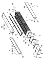
- It is a block diagram which shows an example which mounts a power-source device on a hybrid vehicle which runs by an engine and a motor. It is a block diagram which shows the example which mounts the power-source device on the electric vehicle which runs only by a motor. It is a block diagram which shows the example which applies to the power-source device for electricity storage. It is a perspective view which shows the conventional power supply device.
- each element constituting the present invention may be configured such that a plurality of elements are composed of the same member and the plurality of elements are combined with one member, or conversely, the function of one member is performed by the plurality of members. It can also be shared and realized.
- the contents described in some examples and embodiments can be used in other embodiments and embodiments.
- the power supply device is a power source mounted on an electric vehicle such as a hybrid vehicle or an electric vehicle to supply electric power to a traveling motor, a power source for storing natural energy generated power such as solar power generation or wind power generation, or a power source for storing electric power generated by natural energy such as solar power generation and wind power generation. It is used for various purposes such as a power source for storing midnight power, and is particularly suitable as a power source suitable for high power and large current applications.
- an embodiment applied to a power supply device for driving an electric vehicle will be described.
- FIG. 1 is a perspective view showing a power supply device according to the first embodiment
- FIG. 2 is an exploded perspective view of the power supply device of FIG. 1
- FIG. 3 is a perspective view showing a battery cell and a separator of FIG. 4 is a cross-sectional view of the power supply device of FIG. 1 with a partially enlarged view on the IV-IV line
- FIG. 6 is a cross-sectional view of the cover portion of FIG. 2 on the VI-VI line
- FIG. 7 is VII-VII of the power supply device of FIG. Schematic vertical cross-sectional views of the lines are shown respectively.
- the power supply device 100 shown in these figures includes a battery laminate 2 in which a plurality of battery cells 1 are laminated, a pair of end plates 3 arranged at both ends of the battery laminate 2 in the stacking direction, and a pair of ends. Both ends are connected to the plate 3, and a pair of fastening members 4 for fastening the battery laminate 2 and a cover portion 60 for covering the upper surface of the battery laminate 2 are provided.
- Battery cell 1 Battery cell 1
- the battery cell 1 is a square battery having a width W wider than a thickness T, in other words, a square battery thinner than the width, and is laminated in the thickness direction to form a battery laminate 2.
- the battery cell 1 can be, for example, a lithium ion secondary battery. Further, the battery cell can be any rechargeable secondary battery such as a nickel hydrogen battery or a nickel cadmium battery.
- positive and negative electrode plates are housed together with an electrolytic solution in an outer can 1a having a closed structure.
- a metal plate such as aluminum or an aluminum alloy is press-molded into a square shape, and the opening is airtightly sealed with a sealing plate 1b.
- the sealing plate 1b is made of the same aluminum or aluminum alloy as the square outer can 1a, and positive and negative electrode terminals 11 are fixed to both ends. Further, the sealing plate 1b is provided with a gas discharge valve 13 which is a safety valve that opens in response to a pressure change inside each of the battery cells 1 between the positive and negative electrode terminals 11.
- the plurality of battery cells 1 are laminated so that the thickness direction of each battery cell 1 is the stacking direction to form the battery laminate 2. At this time, the output of the battery laminate 2 can be increased by increasing the number of layers to be larger than usual. In such a case, the battery laminate 2 becomes a long one extended in the stacking direction.
- terminal surfaces 10 provided with positive and negative electrode terminals 11 are arranged on the same plane, and a plurality of battery cells 1 are laminated to form a battery laminate 2.
- the upper surface of the battery laminate 2 is a surface provided with gas discharge valves 13 of a plurality of battery cells 1. (Separator 30)
- the battery laminate 2 has a separator 30 sandwiched between the stacked battery cells 1. Further, the separator 30 is provided on the mounting plate portion 31 forming the main surface of the separator 30, the upper peripheral wall 32 provided on the upper peripheral edge of the mounting plate portion 31, and both side portions on the short side side of the mounting plate portion 31. It is provided with a vertical wall 33.
- the mounting plate portion 31 is a portion sandwiched between the battery cells 1 adjacent to each other.
- the mounting plate 31 has a plate shape having a size substantially equal to the facing surface of the battery cells 1, and the separators 12 are laminated between the battery cells 1 adjacent to each other to insulate the adjacent battery cells 1 from each other. .. Further, the mounting plate portion 31 has a rectangular shape having a long side and a short side long in the width W direction, substantially similar to the facing surface of the battery cell 1.
- the upper peripheral wall 32 is formed at the upper end of the mounting plate portion 31 and is locked to the sealing plate 1b of the battery cell 1.
- a separator-side locking piece 34 which will be described later, is provided on the upper surface of the upper peripheral wall 32.
- the longitudinal wall 33 is formed so as to be orthogonal to the narrowed plate portion 31.
- the lower end of the vertical wall 33 slightly protrudes toward one of the adjacent battery cells 1, and is partially bent along the bottom of the narrow-fitting plate portion 31.
- the separator 30 can be easily self-supported, and the lower corner portion of the adjacent battery cell 1 can be held by the protruding portion and the bent portion, so that the adjacent battery cell 1 is narrowly attached. It can be more reliable.
- a metal bus bar 14 is connected to the positive and negative electrode terminals 11 of the adjacent battery cells 1, and a plurality of battery cells 1 are connected in series or in parallel, or in parallel with the series by the bus bar 14.
- a bus bar holder may be arranged between the battery laminate 2 and the bus bar. By using the bus bar holder, a plurality of bus bars can be arranged at a fixed position on the upper surface of the battery laminate while insulating the plurality of bus bars from each other and insulating the terminal surface of the battery cell and the bus bar.
- the bus bar 14 is manufactured into a predetermined shape by cutting and processing a metal plate.
- a metal plate constituting the bus bar a metal having low electric resistance and light weight, for example, an aluminum plate or a copper plate, or an alloy thereof can be used.
- other metals with low electrical resistance and light weight and alloys thereof can also be used.
- the end plates 3 are arranged on both end faces with the end face spacers 12 interposed therebetween. As shown in FIG. 2, the end face spacer 12 is arranged between the battery laminate 2 and the end plate 3 to insulate the end plate 3 from the battery laminate 2.
- the end face spacer 12 can be made of the same material as the separator 30 described above. (End plate 3)
- the end plates 3 are arranged at both ends of the battery laminate 2 and are fastened via fastening members 4 arranged along both side surfaces of the battery laminate 2.
- the end plates 3 are both ends of the battery laminate 2 in the stacking direction of the battery cells 1 and are arranged outside the end face spacer 12 to sandwich the battery laminate 2 from both ends.
- the end plate 3 can be made of metal.
- each end plate 3 can make the rigidity of the upper end portion stronger than the rigidity of the central portion.
- the end plate 3 has a quadrangular outer shape and is arranged so as to face the end face of the battery laminate 2.
- the end plate 3 shown in FIG. 2 has an outer shape substantially equal to the outer shape of the battery cell 1. That is, the width of the end plate 3 shown in the figure is equal to the width of the battery cell 1 in the left-right direction, and the height in the vertical direction is equal to the height of the battery cell 1.
- the vertical direction is defined as the vertical direction in the drawing
- the horizontal direction is defined as the horizontal direction in the drawing, which is orthogonal to the stacking direction of the batteries.
- the method of fixing the end plate is not particularly limited.
- the end plate 3 shown in FIGS. 1 and 2 has a plurality of through holes for fixing the end plate 3.
- the end plate 3 has a first through hole 36 for inserting a fastener 19 for fixing the fastening member side fixing portion 41 of the fastening member 4.
- the end plate 3 shown in the figure has a plurality of through holes as the first through holes 36.
- the end plate 3 in the figure is provided with a plurality of first through holes 36 separated vertically at positions facing the fastening member side fixing portion 41 on both side portions.
- the end plate 3 of FIG. 2 is provided with three first through holes 36 along each side, for a total of six first through holes 36.
- a fastener 19 penetrating the fastening member side fixing portion 41 arranged on the outer peripheral surface is inserted into the first through hole 36.
- the fastener 19 inserted into the first through hole 36 is fixed to the first through hole 36 to fix the fastening member side fixing portion 41 in a fixed position. (Fastening member 4)
- the fastening member 4 is extended in the stacking direction of the battery laminate 2, and both ends thereof are fixed to end plates 3 arranged on both end surfaces of the battery laminate 2, and the end plate 3 is fixed.
- the battery laminate 2 is fastened in the stacking direction via the above.
- the fastening member 4 is a metal plate having a predetermined width and a predetermined thickness along the side surface of the battery laminate 2, and is arranged so as to face both side surfaces of the battery laminate 2.
- a metal plate such as iron, preferably a steel plate, can be used for the fastening member 4.
- the fastening member 4 made of a metal plate is bent by press molding or the like to form a predetermined shape.
- the fastening member 4 is a fastening member main body 40 arranged along the side surface of the battery laminate 2, and a fastening member that is bent at both ends of the fastening member main body 40 and fixed to the outer surface of the end plate 3. It is provided with a side fixing portion 41.
- the fastening member main body 40 has a rectangular shape having a size that covers substantially the entire battery laminate 2 and the end plates 3 arranged at both ends thereof.
- the fastening member main body 40 shown in FIGS. 1 and 2 covers almost the entire side surface of the battery laminate 2 without gaps.
- the fastening member main body 40 may be provided with one or more openings so that a part of the side surface of the battery laminate can be exposed.
- both ends thereof are bent along the outer surface of the end plate 3 to provide the fastening member side fixing portion 41.
- the fastening member side fixing portion 41 shown in FIGS. 1 and 2 covers both the left and right side portions of the end plate 3 so as to be substantially equal to the height of the fastening member main body portion 40 and the end plate 3 in the vertical direction.
- the fastening member 4 is fixed to the end plate 3 via a fastener 19 inserted into a through hole 42 provided at the tip of the fastening member side fixing portion 41.
- the fastening member 4 includes a bent portion 44 that holds the upper surface and the lower surface of the battery laminate 2 along the upper end portion of the intermediate portion excluding both ends of the fastening member main body 40.
- the bent portion 44 holds the upper surface and the lower surface of the battery cells 1 constituting the battery stack 2, and suppresses the position of the terminal surface 10 of each battery cell 1 from being displaced up and down. (Cover 60)
- the power supply device 100 includes a cover portion 60 that is above the battery laminate 2 and covers the upper surface of the battery laminate 2.
- the cover portion 60 has a substantially long rectangular shape having a long side and a short side. Further, the aspect ratio of the long side and the short side of the rectangular shape is preferably 5 or more. This makes it possible to support a long battery laminate 2 having a large number of battery cells stacked. Specifically, the long side is about 1 m to 1 m 20 cm, and the short side is about 140 mm to 170 mm.
- the cover portion 60 includes a cover main body portion 61 mainly made of an insulating resin and a locking claw portion 62. (Locking claw portion 62)
- the locking claw portion 62 is a form of a fixture for fixing the cover portion 60 to the separator 30.
- the position and number of the locking claws 62 are not particularly limited.
- the cover portion 60 includes a locking claw portion 62 with the locking claw portions 62C offset to the right side of both end portions and 62A to the left side along the extension direction.
- a locking claw portion 62B is provided in the central portion.
- the locking claws 62 adjacent to each other in the extension direction are provided at substantially equal intervals. By providing the locking claws 62 at equal intervals, the cover 60 can be fixed to the battery laminate 2 side in a well-balanced manner.
- the present invention is not limited to the mode in which the locking claws 62 are provided at equal intervals.
- it may be provided at close intervals at places where the fixing is desired to be strengthened.
- the locking claws 62C on the front side are provided at close intervals to strengthen the fixing of the right end.
- each locking claw portion 62 is formed in a claw shape.
- the locking claw portion 62 extends downward from the cover main body portion 61.
- the locking claw extending portion 62a extending downward while slightly inclining from the cover main body portion 61 toward the separator side locking piece 34 described later, and the tip side of the locking claw extending portion 62a.
- the locking claw protrusion 62b provided in the above is formed.
- the locking claw protrusion 62b includes a locking claw inclined surface 62ba that is inclined obliquely upward from the tip of the locking claw extending portion 62a toward the separator-side locking piece 34, and a cover main body 61. It is provided with a substantially parallel locking claw contact surface 62bb.
- the protruding direction of the locking claw protrusion 62b is not particularly limited as long as it can engage with the corresponding receiving portion (details will be described later).
- the locking claw protrusion 62b of the locking claw portion 62A is directed to the right side.
- the locking claw protrusion 62b of the locking claw portion 62C is oriented so as to face the left side.
- the locking claw protrusion 62b of the locking claw portion 62B provided in the central portion of the cover portion 60 faces the right side in the example of FIG. 6, but may face either the left or right direction. (Separator side locking piece 34)
- the separator 30 is provided on the upper surface of the upper peripheral wall 32 with a receiving portion for receiving the locking claw portion 62 of the cover portion 60.
- the separator-side locking piece 34 is an aspect of a receiving portion that receives the locking claw portion 62. As shown in FIGS. 3 and 4, the separator-side locking piece 34 is formed in a claw shape that can be locked with the locking claw portion 62.
- the separator-side locking piece 34 extends upward from the upper surface of the upper peripheral wall 32. Specifically, a separator-side extending portion 34a formed substantially perpendicular to the upper surface of the upper peripheral wall 32 and a separator-side protruding portion 34b provided on the tip end side of the separator-side extending portion 34a are formed. ..
- the separator-side protrusion 34b is a separator that is substantially parallel to the separator-side inclined surface 34ba that is inclined diagonally downward from the tip of the separator-side extending portion 34a toward the locking claw portion 62 and the upper surface of the upper peripheral wall 32. It is provided with a side contact surface 34bb.
- the present invention is not limited to the mode in which the separator is used as the structure for fixing the cover portion 60 to the battery laminate 2 side.
- a holder portion may be provided to fix the cover portion 60 to the holder portion.
- the holder portion 50 of the modified example 1 is provided between the upper surface of the battery laminate 2 and the cover portion 60 as shown in FIG. 5, and covers the entire upper surface of the battery laminate 2.
- the holder portion 50 forms locking holes 51, which are receiving portions for receiving the locking claw portion 62 of the cover portion 60, on both end sides and the central portion along the extension direction. That is, the holder portion 50 opens a locking hole 51 into which the locking claw portion 62 is inserted at a position corresponding to the locking claw portion 62.
- the locking claw portion 62 is inserted into the locking hole 51, the tip portion of the cover portion side inclined portion 62b is brought into contact with the lower surface side of the holder portion 50, and the cover portion 60 is locked to the holder portion 50. .. Even with such a configuration, the cover portion 60 can be reliably fixed to the holder portion 50. The mechanical stability of the cover portion 60 is increased, and the cover portion 50 can be prevented from coming off even under the pressure of high-pressure gas when the gas is discharged.
- the configuration of the holder portion 50 can be further simplified by also serving as a bus bar holder for holding the bus bar. Further, the holder unit 50 may be provided with a voltage detection unit or the like for detecting the voltage of the battery cell 1. Furthermore, the holder portion 50 is preferably formed of an insulating resin so that the battery laminate 2 is not short-circuited.
- the separator may be manufactured in the form of a thin plate or sheet with an insulating material. By doing so, the structure of the separator can be simplified.
- the size and shape of the separator are not particularly limited.
- the separator may have a shape in which a flow path of a cooling gas is formed between the battery cell 1 and the spacer.
- the surface of the battery cell 1 can be covered with an insulating material.
- the surface of the outer can 1a excluding the electrode portion of the battery cell may be heat-welded with a shrink tube or a shrink film such as PET resin. (Core material 63)
- the cover portion 60 is insert-molded with a metal core material 63 into the resin cover main body portion 61.
- the thickness CT of the cover main body 61 is about 2 mm to 3 mm.
- the core material 63 has a plate shape slightly smaller than the cover portion 60, and has a shape that can substantially cover the entire upper surface side of the battery laminate 2.
- the metal core material 63 suppresses warpage and waviness. Therefore, the locking claw portion 62 can be formed at a desired position, and the reliability of fixing to the battery assembly 2 can be improved. Further, it is possible to improve the safety by avoiding the supply of external air from the warp or swell of the cover portion 60.
- the core material 63 is a metal plate having excellent thermal conductivity and rigidity.
- a metal plate having excellent thermal conductivity and rigidity.
- an iron plate a stainless steel plate, a high-tensile plate, an aluminum plate, or the like.
- a mesh-like shape or a grid-like shape may be used.
- the core material 63 is embedded in the cover main body 61 .
- the core material of the present invention is not limited to the above aspect.
- a part of the core material may be exposed from the cover main body.
- the exposed portion can be the end portion in the longitudinal direction of the cover body or the side surface.
- the cover portion according to the second embodiment is shown in the vertical sectional view of FIG. In this example, both ends of the core material 63B in the longitudinal direction are projected from the cover main body 61.
- the core material 63B of the cover portion 60B includes a pair of exposed portions 64 that are exposed from both ends in the longitudinal direction of the cover main body portion 61.
- Each of the exposed portions 64 extends downward from the end of the cover main body 61 and the exposed piece 64a on the upper surface 3a side of the end plate 3 in the horizontal direction along the upper surface 3a of the end plate 3. It includes the existing exposed piece 64b.
- the cover portion 60B can be fixed to the battery laminate 2 side.
- the core material 63B is also fixed to the end plate 3, so that the cover portion 60B is more difficult to come off from the battery laminate 2 side.
- the fixed structure made of metal stabilizes the mechanical strength of the fixing. Further, by fixing the metal end plate and the metal core body, the effect of improving heat dissipation can be obtained.
- the position where the core material is exposed from the cover main body portion is not limited to the peripheral direction of the cover main body, and may be the main surface side.
- FIGS. 9 and 10 Such an example is shown in FIGS. 9 and 10 as the cover portion 60C according to the third embodiment.
- the core material 63C is exposed from the entire upper surface of the cover main body portion 61C.
- the portion of the core 63C exposed from the cover main body 61C can be enlarged.
- the heat dissipation from the exposed portion of the core material 63C to the outside can be further enhanced.
- the metal core material of the present invention is not limited to the above-mentioned plate shape.
- a wire rod such as an iron wire or a rod-shaped one can be adopted.
- a plurality of wire rods 63Da are embedded in the cover portion 60D in the lateral direction at predetermined intervals.
- the diameter of the wire rod 63Da is approximately 1 mm to 1.5 mm.
- the plate-shaped core material is spread and covered on the upper surface side of the battery assembly 2, and a gap is formed between the wires like the core material of the fourth embodiment. Not. Therefore, even if the high-pressure gas is released, it is possible to prevent the gas from passing through the gap and blowing through to the outside of the power supply device.
- the above power supply device 100 can be used as a power source for a vehicle that supplies electric power to a motor that runs an electric vehicle.
- an electric vehicle such as a hybrid vehicle or a plug-in hybrid vehicle that runs on both an engine and a motor, or an electric vehicle that runs only on a motor can be used, and is used as a power source for these vehicles. Will be done.
- a large number of the above-mentioned power supply devices 100 are connected in series or in parallel, and a large-capacity, high-output power supply device to which a necessary control circuit is added is constructed. To do. (Power supply for hybrid vehicles)
- FIG. 12 shows an example in which the power supply device 100 is mounted on a hybrid vehicle traveling by both an engine and a motor.
- the vehicle HV equipped with the power supply device 100 shown in this figure is driven by a vehicle main body 91, an engine 96 for running the vehicle main body 91, a running motor 93, and these engines 96 and a running motor 93. It includes wheels 97, a power supply device 100 that supplies electric power to the motor 93, and a generator 94 that charges the batteries of the power supply device 100.
- the power supply device 100 is connected to the motor 93 and the generator 94 via the DC / AC inverter 95.
- the vehicle HV runs on both the motor 93 and the engine 96 while charging and discharging the battery of the power supply device 100.
- the motor 93 is driven to drive the vehicle in a region where the engine efficiency is low, for example, when accelerating or traveling at a low speed.
- the motor 93 is driven by being supplied with electric power from the power supply device 100.
- the generator 94 is driven by the engine 96 or by regenerative braking when braking the vehicle to charge the battery of the power supply device 100.
- the vehicle HV may be provided with a charging plug 98 for charging the power supply device 100. By connecting the charging plug 98 to an external power source, the power supply device 100 can be charged. (Power supply for electric vehicles)
- FIG. 13 shows an example in which the power supply device 100 is mounted on an electric vehicle traveling only by a motor.
- the vehicle EV equipped with the power supply device 100 shown in this figure supplies electric power to the vehicle body 91, the running motor 93 for running the vehicle body 91, the wheels 97 driven by the motor 93, and the motor 93. It includes a power supply device 100 to be supplied and a generator 94 for charging the battery of the power supply device 100.
- the power supply device 100 is connected to the motor 93 and the generator 94 via the DC / AC inverter 95.
- the motor 93 is driven by being supplied with electric power from the power supply device 100.
- the generator 94 is driven by the energy used for regenerative braking of the vehicle EV to charge the battery of the power supply device 100.
- the vehicle EV is provided with a charging plug 98, and the charging plug 98 can be connected to an external power source to charge the power supply device 100. (Power supply device for power storage device)
- the present invention does not specify the use of the power supply device as the power supply of the motor that runs the vehicle.
- the power supply device according to the embodiment can also be used as a power source for a power storage device that charges and stores a battery with electric power generated by solar power generation, wind power generation, or the like.
- FIG. 14 shows a power storage device in which the battery of the power supply device 100 is charged by the solar cell 82 to store electricity.
- the power storage device shown in FIG. 14 charges the battery of the power supply device 100 with the electric power generated by the solar cells 82 arranged on the roof or roof of a building 81 such as a house or factory.
- This power storage device uses the solar cell 82 as a power source for charging, charges the battery of the power supply device 100 with the charging circuit 83, and then supplies power to the load 86 via the DC / AC inverter 85. Therefore, this power storage device has a charge mode and a discharge mode.
- the DC / AC inverter 85 and the charging circuit 83 are connected to the power supply device 100 via the discharge switch 87 and the charging switch 84, respectively.
- the ON / OFF of the discharge switch 87 and the charge switch 84 is switched by the power controller 88 of the power storage device.
- the power controller 88 switches the charging switch 84 to ON and the discharge switch 87 to OFF to allow the charging circuit 83 to charge the power supply device 100.
- the power controller 88 turns off the charging switch 84 and turns on the discharge switch 87 to switch to the discharge mode, and the power supply device 100 Allows discharge from to load 86.
- the charge switch 84 can be turned on and the discharge switch 87 can be turned on to supply power to the load 86 and charge the power supply device 100 at the same time.
- the power supply device can also be used as a power source for a power storage device that charges and stores batteries by using midnight power at night.
- a power supply device charged with midnight power can be charged with midnight power, which is surplus power of a power plant, and output power in the daytime when the power load is large, so that the peak power in the daytime can be limited to a small value.
- the power supply can also be used as a power source for charging with both solar cell output and midnight power. This power supply device can effectively utilize both the power generated by the solar cell and the midnight power, and can efficiently store electricity while considering the weather and power consumption.
- the above-mentioned power storage system includes a backup power supply device that can be mounted in a rack of a computer server, a backup power supply device for a wireless base station such as a mobile phone, a power storage power supply for home or factory use, a power supply for street lights, etc. It can be suitably used for power storage devices combined with solar cells, backup power sources for traffic lights and road traffic indicators, and the like.
- the power supply device according to the present invention and the vehicle provided with the power supply device are suitably used as a power source for a large current used for a power source of a motor for driving an electric vehicle such as a hybrid vehicle, a fuel cell vehicle, an electric vehicle, and an electric motorcycle.
- a power supply device for a plug-in type hybrid electric vehicle, a hybrid electric vehicle, an electric vehicle, or the like that can switch between an EV driving mode and a HEV driving mode can be mentioned.
- a backup power supply device that can be mounted in a computer server rack, a backup power supply device for wireless base stations such as mobile phones, a power storage device for home use and factories, a power storage device for street lights, etc. , Can also be used as appropriate for backup power supplies such as traffic lights.
- Fastening member side fixing part 42 ... Through hole , 44 ... Bent part, 50 ... Holder part, 51 ... Locking hole, 60, 60B, 60C, 60D ... Cover part, 61, 61C ... Cover body part, 62, 62A, 62B, 62C ... Locking claw part, 62a ... Locking claw extension part, 62b ... Locking claw protrusion; 62ba ... Locking claw inclined surface; 62bb ... Locking claw contact surface, 63, 63B, 63C, 63D ... Core material, 63Da ... Wire rod, 64 ... exposed part, 64a, 64b ... exposed piece, 65 ... screw, 81 ... building, 82 ...
- solar battery 83 ... charging circuit, 84 ... charging switch, 85 ... DC / AC inverter, 86 ... load, 87 ... discharge Switch, 88 ... power controller, 91 ... vehicle body, 93 ... motor, 94 ... generator, 95 ... DC / AC inverter, 96 ... engine, 97 ... wheels, 98 ... charging plug, 900 ... power supply, 901 ... battery cell , 902 ... spacer, 903 ... end plate, 904 ... bind bar, 905 ... top cover, 906 ... screw, HV ... vehicle, EV ... vehicle, T ... battery cell thickness, W ... battery cell width, CT ... cover Body thickness
Abstract
In order to provide a power supply device which can be stably attached to a battery layered body even when a top cover covering the battery layered body is elongated, an electric vehicle using the same, and a power storage device, this power supply device comprises: a battery assembly (2) that has a plurality of battery cells (1) and that is extended in one direction; and an insulating cover part (60) that covers one surface extended in the one direction, of the battery assembly (2). The cover part (60) has a plurality of fixing parts for fixing to the upper surface side of the battery assembly (2), the fixing parts being formed in the extending direction. The cover part (60) includes a metal core material (63).
Description
本発明は、電源装置及びこれを用いた電動車両並びに蓄電装置に関する。
The present invention relates to a power supply device, an electric vehicle using the power supply device, and a power storage device.
電源装置は、電動車両の駆動用の電源装置や蓄電用の電源装置等に利用されている。このような電源装置は、充放電可能な複数の電池セルを複数枚積層している。例えば図15の斜視図に示す電源装置900のように、角型の外装缶の電池セル901を、絶縁性のスペーサ902と交互に積層した電池積層体として、その両側の端面に、それぞれエンドプレート903を配置し、エンドプレート903同士を金属製のバインドバー904で締結している。また電池積層体の上面には、絶縁性の樹脂等でトップカバー905が設けられる。このようなトップカバーは、所定の間隔でネジ906や爪を利用して電池積層体の上面に嵌合されている。
The power supply device is used as a power supply device for driving an electric vehicle, a power supply device for storing electricity, and the like. In such a power supply device, a plurality of rechargeable and dischargeable battery cells are stacked. For example, as in the power supply device 900 shown in the perspective view of FIG. 15, the battery cells 901 of the square outer can are formed into a battery laminate in which the battery cells 901 of the square outer can are alternately laminated with the insulating spacers 902, and end plates are provided on both end faces thereof. The 903 is arranged, and the end plates 903 are fastened to each other with a metal bind bar 904. Further, a top cover 905 is provided on the upper surface of the battery laminate with an insulating resin or the like. Such a top cover is fitted to the upper surface of the battery laminate using screws 906 and claws at predetermined intervals.
近年は高容量化の要求に伴い、電池積層体を構成する電池セルの積層数が増大する傾向にある。この結果、電池積層体の全長が電池セルの数に応じて長くなり、これに従ってトップカバーの長さも長くなる。しかしながら、トップカバーの幅に対して長さが長くなると、縦横のアスペクト比が悪化し、樹脂成型されたトップカバーのうねりや反りが大きくなる。この結果、ネジや爪の位置が変化して、嵌合が行えなくなる問題があった。また、トップカバーにうねりや反りがあると、トップカバーと電池積層体との隙間が形成され、電池セルのいずれかが万一熱暴走した際には、この隙間から空気が入り込み、酸素が燃焼して炎が発生することも考えられる。
In recent years, the number of stacked battery cells constituting the battery laminate has tended to increase with the demand for higher capacity. As a result, the total length of the battery laminate increases according to the number of battery cells, and the length of the top cover also increases accordingly. However, when the length is longer than the width of the top cover, the aspect ratio in the vertical and horizontal directions is deteriorated, and the swell and warp of the resin-molded top cover are increased. As a result, there is a problem that the positions of the screws and the claws change and the fitting cannot be performed. In addition, if the top cover has undulations or warpage, a gap is formed between the top cover and the battery laminate, and if any of the battery cells should have a thermal runaway, air will enter through this gap and oxygen will burn. It is also possible that a flame will be generated.
このような成型の精度低下を回避するために、トップカバーを分割することも考えられるが、この場合は部品点数が増えて組み立て工数が増え、コストが上昇する等問題があった。
It is conceivable to divide the top cover in order to avoid such a decrease in molding accuracy, but in this case, there are problems such as an increase in the number of parts, an increase in assembly man-hours, and an increase in cost.
本発明の目的の一は、電池積層体を覆うトップカバーが長尺になっても、電池積層体に安定的に取り付け可能とした電源装置及びこれを用いた電動車両並びに蓄電装置を提供することにある。
One object of the present invention is to provide a power supply device capable of being stably attached to the battery laminate even if the top cover covering the battery laminate becomes long, and an electric vehicle and a power storage device using the same. It is in.
本発明の第1の側面に係る電源装置によれば、複数の電池セルを有する、一方向に延長された電池集合体と、前記電池集合体の一方向に延長された一面を覆う絶縁性のカバー部とを備える電源装置であって、前記カバー部は、前記電池集合体の上面側に固定するための固定具を、延長方向に沿って複数形成しており、前記カバー部は、金属製の芯材を含むことができる。上記構成により、絶縁製のカバー部が延長された細長い形状となっても、金属製の芯材によって反りやうねりを抑制して、固定具を所定の位置に形成することが可能となって電池集合体への固定の信頼性を高めることができる。
According to the power supply device according to the first aspect of the present invention, an insulating battery assembly having a plurality of battery cells and extending in one direction and one surface extending in one direction of the battery assembly are covered. A power supply device including a cover portion, wherein the cover portion forms a plurality of fixtures for fixing to the upper surface side of the battery assembly along the extension direction, and the cover portion is made of metal. Core material can be included. With the above configuration, even if the insulating cover has an extended elongated shape, the metal core material suppresses warpage and swell, and the fixture can be formed in a predetermined position. The reliability of fixation to the aggregate can be increased.
また、第2の側面に係る電源装置によれば、上記構成に加えて、前記複数の電池セルが、それぞれ外装缶を角型としており、前記電池集合体が、複数の電池セルを積層した積層体であり、前記電源装置がさらに、前記複数の電池セルを積層した前記電池積層体の両側端面を覆う一対のエンドプレートと、前記複数の電池セルを積層した状態で、該電池セル同士の間に挟着されるセパレータとを備えており、前記セパレータが、前記カバー部を固定した状態で、前記固定具と対応する位置に、該固定具を受ける受け部を備えることができる。
Further, according to the power supply device according to the second side surface, in addition to the above configuration, the plurality of battery cells each have a square outer can, and the battery assembly is a laminated stack of a plurality of battery cells. A body, and the power supply device is between a pair of end plates covering both end faces of the battery laminate in which the plurality of battery cells are laminated, and a state in which the plurality of battery cells are laminated. The separator is provided with a separator sandwiched between the two, and the separator can be provided with a receiving portion for receiving the fixture at a position corresponding to the fixture in a state where the cover portion is fixed.
また、第3の側面に係る電源装置によれば、上記何れかの構成に加えて、前記電源装置がさらに、前記カバー部と前記電池セルの積層体の上面との間に設けられるホルダ部を備え、前記ホルダ部が、前記カバー部を固定した状態で、前記固定具と対応する位置に、該固定具を受ける受け部を形成することができる。
Further, according to the power supply device according to the third side surface, in addition to any of the above configurations, the power supply device further provides a holder portion provided between the cover portion and the upper surface of the laminated body of the battery cells. In the state where the holder portion fixes the cover portion, a receiving portion for receiving the fixture can be formed at a position corresponding to the fixture.
さらに、第4の側面に係る電源装置によれば、上記何れかの構成に加えて、前記複数の電池セルが、それぞれ内部の圧力変化に応じて開弁する安全弁を備えており、前記電池集合体の上面を、前記複数の電池セルの、前記安全弁を設けた面とすることができる。上記構成により、万一安全弁が開弁されて高圧のガスが電池積層体の上面から放出されても、カバー部の変形を芯材によって抑制し、安全性の向上が図られる。
Further, according to the power supply device according to the fourth aspect, in addition to any of the above configurations, the plurality of battery cells each include a safety valve that opens in response to a change in internal pressure, and the battery assembly. The upper surface of the body can be the surface of the plurality of battery cells provided with the safety valve. With the above configuration, even if the safety valve is opened and high-pressure gas is discharged from the upper surface of the battery laminate, the deformation of the cover portion is suppressed by the core material, and the safety is improved.
さらにまた、第5の側面に係る電源装置によれば、上記何れかの構成に加えて、前記カバー部が、樹脂製であり、前記芯材を、板状に形成することができる。上記構成により、芯材が板状であるため、電池集合体の上面一帯を隙間なく覆うことができる。これにより、電池集合体の上面側の強度を増し、電池集合体への信頼性を高めることができる。また、樹脂製のカバー部で絶縁性を確保しつつ、カバー部が延長された細長い形状となっても板状の芯材でカバー部の反りやうねりを抑制することができる。
Furthermore, according to the power supply device according to the fifth side surface, in addition to any of the above configurations, the cover portion is made of resin, and the core material can be formed in a plate shape. With the above configuration, since the core material is plate-shaped, the entire upper surface of the battery assembly can be covered without gaps. As a result, the strength of the upper surface side of the battery assembly can be increased, and the reliability of the battery assembly can be improved. Further, while ensuring the insulating property with the resin cover portion, even if the cover portion has an elongated shape, the plate-shaped core material can suppress the warp and swell of the cover portion.
さらにまた、第6の側面に係る電源装置によれば、上記何れかの構成に加えて、前記板状の芯材の、少なくとも一部を前記カバー部から表出させることができる。上記構成により、カバー部から表出された芯材の部分から外部への放熱性を高められる。
Furthermore, according to the power supply device according to the sixth side surface, in addition to any of the above configurations, at least a part of the plate-shaped core material can be exposed from the cover portion. With the above configuration, heat dissipation from the core material portion exposed from the cover portion to the outside can be enhanced.
さらにまた、第7の側面に係る電源装置によれば、上記何れかの構成に加えて、前記板状の芯材が、その両端部に、前記カバー部から表出させて前記一対のエンドプレートの上面までそれぞれ延在されて固定する表出部を備えることができる。上記構成により、カバー部の固定具に加えて、芯材もエンドプレートに固定するため、カバー部が電池積層体側から外れにくくなる。
Furthermore, according to the power supply device according to the seventh side surface, in addition to any of the above configurations, the plate-shaped core material is exposed at both ends thereof from the cover portion to expose the pair of end plates. It is possible to provide an exposed portion that extends and fixes to the upper surface of each of the above. With the above configuration, since the core material is also fixed to the end plate in addition to the fixture of the cover portion, the cover portion is less likely to come off from the battery laminate side.
さらにまた、第8の側面に係る電源装置によれば、上記何れかの構成に加えて、前記カバー部が、樹脂製であり、前記芯材を、離間して前記樹脂に埋設された複数の棒状に形成することができる。上記構成により、芯材の体積を低減して、芯材を加えたことによる重量増を抑制できる。
Furthermore, according to the power supply device according to the eighth side surface, in addition to any of the above configurations, the cover portion is made of resin, and the core material is separated and embedded in the resin. It can be formed in a rod shape. With the above configuration, the volume of the core material can be reduced and the weight increase due to the addition of the core material can be suppressed.
さらにまた、第9の側面に係る電源装置によれば、上記何れかの構成に加えて、前記カバー部を、前記芯材にインサート成型することができる。
Furthermore, according to the power supply device according to the ninth side surface, in addition to any of the above configurations, the cover portion can be insert-molded into the core material.
さらにまた、第10の側面に係る電源装置によれば、上記何れかの構成に加えて、前記カバー部が矩形状に形成されており、該矩形状のアスペクト比を5以上とすることができる。
Furthermore, according to the power supply device according to the tenth side surface, in addition to any of the above configurations, the cover portion is formed in a rectangular shape, and the rectangular aspect ratio can be 5 or more. ..
本発明の第11の側面に係る車両によれば、上記何れかの電源装置を備える車両であって、前記電源装置と、該電源装置から電力供給される走行用のモータと、前記電源装置及び前記モータを搭載してなる車両本体と、前記モータで駆動されて前記車両本体を走行させる車輪とを備えることができる。
According to the vehicle according to the eleventh aspect of the present invention, the vehicle including any of the above power supply devices, the power supply device, a traveling motor to which power is supplied from the power supply device, the power supply device, and the vehicle. A vehicle body equipped with the motor and wheels driven by the motor to drive the vehicle body can be provided.
本発明の第12の側面に係る蓄電装置によれば、上記何れかの電源装置を備える蓄電装置であって、前記電源装置と、該電源装置への充放電を制御する電源コントローラとを備えており、前記電源コントローラでもって、外部からの電力により前記電池セルへの充電を可能とすると共に、該電池セルに対し充電を行うよう制御することができる。
According to the power storage device according to the twelfth aspect of the present invention, the power storage device including any of the above power supply devices includes the power supply device and a power supply controller for controlling charging / discharging to the power supply device. Therefore, the power controller can charge the battery cell by electric power from the outside and can control the battery cell to be charged.
以下、本発明の実施形態を図面に基づいて説明する。ただし、以下に示す実施形態は、本発明の技術思想を具体化するための例示であって、本発明は以下のものに特定されない。また、本明細書は、特許請求の範囲に示される部材を、実施形態の部材に特定するものでは決してない。特に実施形態に記載されている構成部材の寸法、材質、形状、その相対的配置等は特に特定的な記載がない限りは、本発明の範囲をそれのみに限定する趣旨ではなく、単なる説明例にすぎない。なお、各図面が示す部材の大きさや位置関係等は、説明を明確にするため誇張していることがある。さらに以下の説明において、同一の名称、符号については同一もしくは同質の部材を示しており、詳細説明を適宜省略する。さらに、本発明を構成する各要素は、複数の要素を同一の部材で構成して一の部材で複数の要素を兼用する態様としてもよいし、逆に一の部材の機能を複数の部材で分担して実現することもできる。また、一部の実施例、実施形態において説明された内容は、他の実施例、実施形態等に利用可能なものもある。
Hereinafter, embodiments of the present invention will be described with reference to the drawings. However, the embodiments shown below are examples for embodying the technical idea of the present invention, and the present invention is not specified as the following. Further, the present specification does not specify the members shown in the claims as the members of the embodiment. In particular, the dimensions, materials, shapes, relative arrangements, and the like of the constituent members described in the embodiments are not intended to limit the scope of the present invention to the specific description unless otherwise specified, and are merely explanatory examples. It's just that. The size and positional relationship of the members shown in each drawing may be exaggerated to clarify the explanation. Further, in the following description, members of the same or the same quality are shown with the same name and reference numeral, and detailed description thereof will be omitted as appropriate. Further, each element constituting the present invention may be configured such that a plurality of elements are composed of the same member and the plurality of elements are combined with one member, or conversely, the function of one member is performed by the plurality of members. It can also be shared and realized. In addition, the contents described in some examples and embodiments can be used in other embodiments and embodiments.
実施形態に係る電源装置は、ハイブリッド車や電気自動車などの電動車両に搭載されて走行用モータに電力を供給する電源、太陽光発電や風力発電などの自然エネルギーの発電電力を蓄電する電源、あるいは深夜電力を蓄電する電源など、種々の用途に使用され、とくに大電力、大電流の用途に好適な電源として使用される。以下の例では、電動車両の駆動用の電源装置に適用した実施形態について、説明する。
[実施形態1] The power supply device according to the embodiment is a power source mounted on an electric vehicle such as a hybrid vehicle or an electric vehicle to supply electric power to a traveling motor, a power source for storing natural energy generated power such as solar power generation or wind power generation, or a power source for storing electric power generated by natural energy such as solar power generation and wind power generation. It is used for various purposes such as a power source for storing midnight power, and is particularly suitable as a power source suitable for high power and large current applications. In the following example, an embodiment applied to a power supply device for driving an electric vehicle will be described.
[Embodiment 1]
本発明の実施形態1に係る電源装置を、図1~図4、図6、図7に示す。これらの図において、図1は実施形態1に係る電源装置を示す斜視図、図2は図1の電源装置の分解斜視図、図3は図2の電池セルとセパレータとを示す斜視図、図4は図1の電源装置のIV-IV線における部分拡大図付き断面図、図6は図2のカバー部のVI-VI線における横断面図、図7は図1の電源装置のVII-VII線における模式縦断面図を、それぞれ示している。これらの図に示す電源装置100は、複数の電池セル1を積層している電池積層体2と、この電池積層体2の積層方向の両端に配置された一対のエンドプレート3と、一対のエンドプレート3に両端が連結されて、電池積層体2を締結する一対の締結部材4と、電池積層体2の上面を覆うカバー部60とを備えている。
(電池セル1) The power supply device according to the first embodiment of the present invention is shown in FIGS. 1 to 4, 6 and 7. In these figures, FIG. 1 is a perspective view showing a power supply device according to the first embodiment, FIG. 2 is an exploded perspective view of the power supply device of FIG. 1, and FIG. 3 is a perspective view showing a battery cell and a separator of FIG. 4 is a cross-sectional view of the power supply device of FIG. 1 with a partially enlarged view on the IV-IV line, FIG. 6 is a cross-sectional view of the cover portion of FIG. 2 on the VI-VI line, and FIG. 7 is VII-VII of the power supply device of FIG. Schematic vertical cross-sectional views of the lines are shown respectively. Thepower supply device 100 shown in these figures includes a battery laminate 2 in which a plurality of battery cells 1 are laminated, a pair of end plates 3 arranged at both ends of the battery laminate 2 in the stacking direction, and a pair of ends. Both ends are connected to the plate 3, and a pair of fastening members 4 for fastening the battery laminate 2 and a cover portion 60 for covering the upper surface of the battery laminate 2 are provided.
(Battery cell 1)
(電池セル1) The power supply device according to the first embodiment of the present invention is shown in FIGS. 1 to 4, 6 and 7. In these figures, FIG. 1 is a perspective view showing a power supply device according to the first embodiment, FIG. 2 is an exploded perspective view of the power supply device of FIG. 1, and FIG. 3 is a perspective view showing a battery cell and a separator of FIG. 4 is a cross-sectional view of the power supply device of FIG. 1 with a partially enlarged view on the IV-IV line, FIG. 6 is a cross-sectional view of the cover portion of FIG. 2 on the VI-VI line, and FIG. 7 is VII-VII of the power supply device of FIG. Schematic vertical cross-sectional views of the lines are shown respectively. The
(Battery cell 1)
電池セル1は、図2に示すように、厚さTに比べて幅Wが広い、言い換えると幅よりも薄い角形電池で、厚さ方向に積層されて電池積層体2としている。電池セル1は、例えば、リチウムイオン二次電池とすることができる。また、電池セルは、ニッケル水素電池、ニッケルカドミウム電池等、充電できる全ての二次電池とすることもできる。電池セル1は、密閉構造の外装缶1aに正負の電極板を電解液と共に収容している。外装缶1aは、アルミニウムやアルミニウム合金等の金属板を角形にプレス成形され、開口部を封口板1bで気密に密閉している。封口板1bは、角型の外装缶1aと同じアルミニウムやアルミニウム合金で、両端部に正負の電極端子11を固定している。さらに、封口板1bは、正負の電極端子11の間に、電池セル1のそれぞれ内部の圧力変化に応じて開弁する安全弁であるガス排出弁13を設けている。
As shown in FIG. 2, the battery cell 1 is a square battery having a width W wider than a thickness T, in other words, a square battery thinner than the width, and is laminated in the thickness direction to form a battery laminate 2. The battery cell 1 can be, for example, a lithium ion secondary battery. Further, the battery cell can be any rechargeable secondary battery such as a nickel hydrogen battery or a nickel cadmium battery. In the battery cell 1, positive and negative electrode plates are housed together with an electrolytic solution in an outer can 1a having a closed structure. In the outer can 1a, a metal plate such as aluminum or an aluminum alloy is press-molded into a square shape, and the opening is airtightly sealed with a sealing plate 1b. The sealing plate 1b is made of the same aluminum or aluminum alloy as the square outer can 1a, and positive and negative electrode terminals 11 are fixed to both ends. Further, the sealing plate 1b is provided with a gas discharge valve 13 which is a safety valve that opens in response to a pressure change inside each of the battery cells 1 between the positive and negative electrode terminals 11.
複数の電池セル1は、各電池セル1の厚み方向が積層方向となるように積層されて電池積層体2を構成している。この際、積層数を通常よりも多めにすることで、電池積層体2の高出力化を図ることができる。斯かる場合、電池積層体2は積層方向に延長された長尺のものとなる。電池セル1は、正負の電極端子11を設けている端子面10を同一平面に配置して、複数の電池セル1を積層して電池積層体2としている。そして、電池積層体2の上面を、複数の電池セル1のガス排出弁13を設けた面としている。
(セパレータ30) The plurality ofbattery cells 1 are laminated so that the thickness direction of each battery cell 1 is the stacking direction to form the battery laminate 2. At this time, the output of the battery laminate 2 can be increased by increasing the number of layers to be larger than usual. In such a case, the battery laminate 2 becomes a long one extended in the stacking direction. In the battery cell 1, terminal surfaces 10 provided with positive and negative electrode terminals 11 are arranged on the same plane, and a plurality of battery cells 1 are laminated to form a battery laminate 2. The upper surface of the battery laminate 2 is a surface provided with gas discharge valves 13 of a plurality of battery cells 1.
(Separator 30)
(セパレータ30) The plurality of
(Separator 30)
電池積層体2は、図2及び図3に示すように、積層している電池セル1の間にセパレータ30を挟着している。また、セパレータ30は、セパレータ30の主面を構成する装着プレート部31と、装着プレート部31の上側周縁に設けられた上周壁32と、装着プレート部31の短辺側の両側部に設けられた縦周壁33を備えている。
As shown in FIGS. 2 and 3, the battery laminate 2 has a separator 30 sandwiched between the stacked battery cells 1. Further, the separator 30 is provided on the mounting plate portion 31 forming the main surface of the separator 30, the upper peripheral wall 32 provided on the upper peripheral edge of the mounting plate portion 31, and both side portions on the short side side of the mounting plate portion 31. It is provided with a vertical wall 33.
装着プレート部31は、互いに隣接する電池セル1の間に挟まれる部分となる。この装着プレート31は電池セル1の対向面とほぼ等しい大きさのプレート状としており、このセパレータ12を互いに隣接する電池セル1の間に積層して、隣接する電池セル1同士を絶縁している。また、装着プレート部31は電池セル1の対向面と概ね同様に、幅W方向に長い長辺と短辺を有する矩形状としている。
The mounting plate portion 31 is a portion sandwiched between the battery cells 1 adjacent to each other. The mounting plate 31 has a plate shape having a size substantially equal to the facing surface of the battery cells 1, and the separators 12 are laminated between the battery cells 1 adjacent to each other to insulate the adjacent battery cells 1 from each other. .. Further, the mounting plate portion 31 has a rectangular shape having a long side and a short side long in the width W direction, substantially similar to the facing surface of the battery cell 1.
上周壁32は、装着プレート部31の上端に形成され、電池セル1の封口板1bに係止される。この上周壁32の上面には、後述するセパレータ側係止片34を備えている。
The upper peripheral wall 32 is formed at the upper end of the mounting plate portion 31 and is locked to the sealing plate 1b of the battery cell 1. A separator-side locking piece 34, which will be described later, is provided on the upper surface of the upper peripheral wall 32.
一方、縦周壁33は、狭着プレート部31と直交するように形成される。縦周壁33は、下側の一端部が、隣接する一方の電池セル1に向かって若干突出し、狭着プレート部31の底辺に沿って一部折り曲げられている。このような形状にすることにより、セパレータ30を自立し易くすると共に、突出部分及び折り曲げられた部分で、隣接する電池セル1の下側角部を保持でき、隣接する電池セル1の狭着をより確実にすることができる。
(電池積層体2) On the other hand, thelongitudinal wall 33 is formed so as to be orthogonal to the narrowed plate portion 31. The lower end of the vertical wall 33 slightly protrudes toward one of the adjacent battery cells 1, and is partially bent along the bottom of the narrow-fitting plate portion 31. With such a shape, the separator 30 can be easily self-supported, and the lower corner portion of the adjacent battery cell 1 can be held by the protruding portion and the bent portion, so that the adjacent battery cell 1 is narrowly attached. It can be more reliable.
(Battery laminate 2)
(電池積層体2) On the other hand, the
(Battery laminate 2)
電池積層体2は、隣接する電池セル1の正負の電極端子11に金属製のバスバー14が接続されて、バスバー14でもって複数の電池セル1を直列又は並列に、あるいは直列と並列に接続される。この電池積層体2とバスバーとの間にバスバーホルダを配置してもよい。バスバーホルダを用いることで、複数のバスバーを互いに絶縁し、かつ電池セルの端子面とバスバーとを絶縁しながら、複数のバスバーを電池積層体の上面の定位置に配置できる。
In the battery laminate 2, a metal bus bar 14 is connected to the positive and negative electrode terminals 11 of the adjacent battery cells 1, and a plurality of battery cells 1 are connected in series or in parallel, or in parallel with the series by the bus bar 14. To. A bus bar holder may be arranged between the battery laminate 2 and the bus bar. By using the bus bar holder, a plurality of bus bars can be arranged at a fixed position on the upper surface of the battery laminate while insulating the plurality of bus bars from each other and insulating the terminal surface of the battery cell and the bus bar.
バスバー14は、金属板を裁断、加工して所定の形状に製造される。バスバーを構成する金属板には、電気抵抗が小さく、軽量である金属、例えばアルミニウム板や銅板、あるいはこれらの合金が使用できる。ただ、バスバーの金属板は、電気抵抗が小さくて軽量である他の金属やこれらの合金も使用できる。
(端面スペーサ12) Thebus bar 14 is manufactured into a predetermined shape by cutting and processing a metal plate. As the metal plate constituting the bus bar, a metal having low electric resistance and light weight, for example, an aluminum plate or a copper plate, or an alloy thereof can be used. However, for the metal plate of the bus bar, other metals with low electrical resistance and light weight and alloys thereof can also be used.
(End face spacer 12)
(端面スペーサ12) The
(End face spacer 12)
電池積層体2は、両端面に端面スペーサ12を挟んでエンドプレート3を配置している。端面スペーサ12は、図2に示すように、電池積層体2とエンドプレート3との間に配置されてエンドプレート3を電池積層体2から絶縁する。端面スペーサ12は、上述したセパレータ30と同様の材質で構成することができる。
(エンドプレート3) In thebattery laminate 2, the end plates 3 are arranged on both end faces with the end face spacers 12 interposed therebetween. As shown in FIG. 2, the end face spacer 12 is arranged between the battery laminate 2 and the end plate 3 to insulate the end plate 3 from the battery laminate 2. The end face spacer 12 can be made of the same material as the separator 30 described above.
(End plate 3)
(エンドプレート3) In the
(End plate 3)
エンドプレート3は、図2に示すように、電池積層体2の両端に配置されると共に、電池積層体2の両側面に沿って配置される締結部材4を介して締結される。エンドプレート3は、電池積層体2の電池セル1の積層方向における両端であって、端面スペーサ12の外側に配置されて電池積層体2を両端から挟着している。また、エンドプレート3は金属製とすることができる。さらに、各エンドプレート3は、上端部分の剛性を中央部分の剛性よりも強くすることができる。
As shown in FIG. 2, the end plates 3 are arranged at both ends of the battery laminate 2 and are fastened via fastening members 4 arranged along both side surfaces of the battery laminate 2. The end plates 3 are both ends of the battery laminate 2 in the stacking direction of the battery cells 1 and are arranged outside the end face spacer 12 to sandwich the battery laminate 2 from both ends. Further, the end plate 3 can be made of metal. Further, each end plate 3 can make the rigidity of the upper end portion stronger than the rigidity of the central portion.
エンドプレート3は、外形を四角形としており、電池積層体2の端面に対向して配置されている。図2に示すエンドプレート3は、電池セル1の外形とほぼ等しい外形としている。すなわち、図に示すエンドプレート3は、左右方向の幅を電池セル1の幅と等しくすると共に、上下方向の高さを電池セル1の高さと等しくしている。なお、本明細書において、上下方向とは図における上下方向とし、左右方向は、図における左右方向であって、電池の積層方向と直交する水平方向を意味するものとする。
The end plate 3 has a quadrangular outer shape and is arranged so as to face the end face of the battery laminate 2. The end plate 3 shown in FIG. 2 has an outer shape substantially equal to the outer shape of the battery cell 1. That is, the width of the end plate 3 shown in the figure is equal to the width of the battery cell 1 in the left-right direction, and the height in the vertical direction is equal to the height of the battery cell 1. In the present specification, the vertical direction is defined as the vertical direction in the drawing, and the horizontal direction is defined as the horizontal direction in the drawing, which is orthogonal to the stacking direction of the batteries.
このエンドプレートを固定する方法は特に限定されない。例えば、図1及び図2に示すエンドプレート3は、エンドプレート3を固定するための貫通孔を複数形成している。また、エンドプレート3は、締結部材4の締結部材側固定部41を固定する留め具19を挿入するための第一貫通孔36を有している。図に示すエンドプレート3は、第一貫通孔36として、複数の貫通孔を開口している。図のエンドプレート3は、両側部であって締結部材側固定部41と対向する位置に、上下に離して複数の第一貫通孔36を設けている。図2のエンドプレート3は、両側に沿って3個ずつ、全体で6個の第一貫通孔36を設けている。このエンドプレート3は、外周面に配置される締結部材側固定部41を貫通する留め具19が第一貫通孔36に挿入される。第一貫通孔36に挿入された留め具19は、第一貫通孔36に固定されて締結部材側固定部41を定位置に固定する。
(締結部材4) The method of fixing the end plate is not particularly limited. For example, theend plate 3 shown in FIGS. 1 and 2 has a plurality of through holes for fixing the end plate 3. Further, the end plate 3 has a first through hole 36 for inserting a fastener 19 for fixing the fastening member side fixing portion 41 of the fastening member 4. The end plate 3 shown in the figure has a plurality of through holes as the first through holes 36. The end plate 3 in the figure is provided with a plurality of first through holes 36 separated vertically at positions facing the fastening member side fixing portion 41 on both side portions. The end plate 3 of FIG. 2 is provided with three first through holes 36 along each side, for a total of six first through holes 36. In the end plate 3, a fastener 19 penetrating the fastening member side fixing portion 41 arranged on the outer peripheral surface is inserted into the first through hole 36. The fastener 19 inserted into the first through hole 36 is fixed to the first through hole 36 to fix the fastening member side fixing portion 41 in a fixed position.
(Fastening member 4)
(締結部材4) The method of fixing the end plate is not particularly limited. For example, the
(Fastening member 4)
締結部材4は、図2に示すように、電池積層体2の積層方向に延長されており、両端が電池積層体2の両端面に配置されたエンドプレート3に固定されて、このエンドプレート3を介して電池積層体2を積層方向に締結している。締結部材4は、電池積層体2の側面に沿う所定の幅と所定の厚さを有する金属板で、電池積層体2の両側面に対向して配置されている。この締結部材4には、鉄などの金属板、好ましくは、鋼板が使用できる。金属板からなる締結部材4は、プレス成形等により折曲加工されて所定の形状に形成される。
As shown in FIG. 2, the fastening member 4 is extended in the stacking direction of the battery laminate 2, and both ends thereof are fixed to end plates 3 arranged on both end surfaces of the battery laminate 2, and the end plate 3 is fixed. The battery laminate 2 is fastened in the stacking direction via the above. The fastening member 4 is a metal plate having a predetermined width and a predetermined thickness along the side surface of the battery laminate 2, and is arranged so as to face both side surfaces of the battery laminate 2. A metal plate such as iron, preferably a steel plate, can be used for the fastening member 4. The fastening member 4 made of a metal plate is bent by press molding or the like to form a predetermined shape.
締結部材4は、電池積層体2の側面に沿って配置される締結部材本体部40と、この締結部材本体部40の両端で折曲されて、エンドプレート3の外側面に固定される締結部材側固定部41とを備えている。締結部材本体部40は、電池積層体2と、その両端に配置されるエンドプレート3のほぼ全体を被覆する大きさの矩形状としている。図1及び図2に示す締結部材本体部40は、電池積層体2の側面のほぼ全面を隙間なく被覆している。ただ、締結部材本体部40は、1以上の開口部を設けて、電池積層体の側面の一部を表出させることもできる。締結部材4は、両端を一対のエンドプレート3に固定するために、その両端部をエンドプレート3の外側面に沿うように折曲加工して締結部材側固定部41を設けている。図1及び図2に示す締結部材側固定部41は、締結部材本体部40及びエンドプレート3の上下方向の高さとほぼ等しくして、エンドプレート3の左右の両側部を被覆している。この締結部材4は、締結部材側固定部41の先端に設けた貫通孔42に挿入される留め具19を介してエンドプレート3に固定される。さらに、締結部材4は、締結部材本体部40の両端部を除く中間部分の上端部に沿って、電池積層体2の上面及び下面を保持する折曲部44を備えている。折曲部44は、電池積層体2を構成する電池セル1の上面及び下面を保持して、各電池セル1の端子面10の位置が上下にずれるのを抑制している。
(カバー部60) Thefastening member 4 is a fastening member main body 40 arranged along the side surface of the battery laminate 2, and a fastening member that is bent at both ends of the fastening member main body 40 and fixed to the outer surface of the end plate 3. It is provided with a side fixing portion 41. The fastening member main body 40 has a rectangular shape having a size that covers substantially the entire battery laminate 2 and the end plates 3 arranged at both ends thereof. The fastening member main body 40 shown in FIGS. 1 and 2 covers almost the entire side surface of the battery laminate 2 without gaps. However, the fastening member main body 40 may be provided with one or more openings so that a part of the side surface of the battery laminate can be exposed. In order to fix both ends of the fastening member 4 to the pair of end plates 3, both ends thereof are bent along the outer surface of the end plate 3 to provide the fastening member side fixing portion 41. The fastening member side fixing portion 41 shown in FIGS. 1 and 2 covers both the left and right side portions of the end plate 3 so as to be substantially equal to the height of the fastening member main body portion 40 and the end plate 3 in the vertical direction. The fastening member 4 is fixed to the end plate 3 via a fastener 19 inserted into a through hole 42 provided at the tip of the fastening member side fixing portion 41. Further, the fastening member 4 includes a bent portion 44 that holds the upper surface and the lower surface of the battery laminate 2 along the upper end portion of the intermediate portion excluding both ends of the fastening member main body 40. The bent portion 44 holds the upper surface and the lower surface of the battery cells 1 constituting the battery stack 2, and suppresses the position of the terminal surface 10 of each battery cell 1 from being displaced up and down.
(Cover 60)
(カバー部60) The
(Cover 60)
電源装置100は、図1~図3に示すように電池積層体2の上方であって、電池積層体2の上面を覆うカバー部60を備えている。カバー部60は、長辺と短辺を有する概ね長尺の矩形状である。また、矩形状の長辺と短辺のアスペクト比は、5以上とすることが好ましい。これにより、電池セルの積層数の多い長尺の電池積層体2に対応できる。具体的には、長辺が概ね1m~1m20cm程度、短辺が概ね140mm~170mm程度である。
As shown in FIGS. 1 to 3, the power supply device 100 includes a cover portion 60 that is above the battery laminate 2 and covers the upper surface of the battery laminate 2. The cover portion 60 has a substantially long rectangular shape having a long side and a short side. Further, the aspect ratio of the long side and the short side of the rectangular shape is preferably 5 or more. This makes it possible to support a long battery laminate 2 having a large number of battery cells stacked. Specifically, the long side is about 1 m to 1 m 20 cm, and the short side is about 140 mm to 170 mm.
カバー部60は、図2の分解斜視図に示すように、絶縁性の樹脂で主に構成されたカバー本体部61と、係止爪部62とを備えている。
(係止爪部62) As shown in the exploded perspective view of FIG. 2, thecover portion 60 includes a cover main body portion 61 mainly made of an insulating resin and a locking claw portion 62.
(Locking claw portion 62)
(係止爪部62) As shown in the exploded perspective view of FIG. 2, the
(Locking claw portion 62)
係止爪部62は、カバー部60をセパレータ30に固定するための固定具の一形態である。この係止爪部62の位置及び数は特に限定されない。一例として図1に示すように、カバー部60は、係止爪部62を延長方向に沿って、両端部の右側に係止爪部62C、左側に62Aをオフセットして備えている。また、中央部分に係止爪部62Bを備えている。延長方向に隣接する係止爪部62は概ね等間隔に設けられる。係止爪部62を等間隔に設けることで、カバー部60をバランスよく電池積層体2側に固定できる。ただ、本発明は係止爪部62を等間隔に設ける態様に限られない。例えば、固定を強化したい箇所に間隔を詰めて設けてもよい。図1の電源装置においては、手前側の係止爪部62Cの間隔を詰めて設け右側端部の固定の強化を図っている。
The locking claw portion 62 is a form of a fixture for fixing the cover portion 60 to the separator 30. The position and number of the locking claws 62 are not particularly limited. As an example, as shown in FIG. 1, the cover portion 60 includes a locking claw portion 62 with the locking claw portions 62C offset to the right side of both end portions and 62A to the left side along the extension direction. Further, a locking claw portion 62B is provided in the central portion. The locking claws 62 adjacent to each other in the extension direction are provided at substantially equal intervals. By providing the locking claws 62 at equal intervals, the cover 60 can be fixed to the battery laminate 2 side in a well-balanced manner. However, the present invention is not limited to the mode in which the locking claws 62 are provided at equal intervals. For example, it may be provided at close intervals at places where the fixing is desired to be strengthened. In the power supply device of FIG. 1, the locking claws 62C on the front side are provided at close intervals to strengthen the fixing of the right end.
図4の断面図及び図6の断面図に示すように、各係止爪部62は、爪状に形成されている。そして、係止爪部62はカバー本体部61から下方に延出している。具体的には、カバー本体部61から後述するセパレータ側係止片34に向かって若干傾斜しつつ下方向に延出する係止爪延出部62aと、係止爪延出部62aの先端側に設けられた係止爪突起部62bを形成している。係止爪突起部62bは、係止爪延出部62aの先端から、セパレータ側係止片34に向かって、斜め上方向に傾斜している係止爪傾斜面62baと、カバー本体部61と概ね平行な係止爪当接面62bbを備えている。
As shown in the cross-sectional view of FIG. 4 and the cross-sectional view of FIG. 6, each locking claw portion 62 is formed in a claw shape. The locking claw portion 62 extends downward from the cover main body portion 61. Specifically, the locking claw extending portion 62a extending downward while slightly inclining from the cover main body portion 61 toward the separator side locking piece 34 described later, and the tip side of the locking claw extending portion 62a. The locking claw protrusion 62b provided in the above is formed. The locking claw protrusion 62b includes a locking claw inclined surface 62ba that is inclined obliquely upward from the tip of the locking claw extending portion 62a toward the separator-side locking piece 34, and a cover main body 61. It is provided with a substantially parallel locking claw contact surface 62bb.
この係止爪突起部62bの突出する向きは、対応する受け部(詳細は後述)と係合できれば、特に限定されない。例えば、図6のカバー部60においては、係止爪部62Aの係止爪突起部62bは右側を向くようにしている。一方、係止爪部62Cの係止爪突起部62bは左側を向くようにしている。さらに、カバー部60の中央部分に設けられる係止爪部62Bの係止爪突起部62bは、図6の例では右側を向いているが、左右いずれか一方向を向いていればよい。
(セパレータ側係止片34) The protruding direction of the lockingclaw protrusion 62b is not particularly limited as long as it can engage with the corresponding receiving portion (details will be described later). For example, in the cover portion 60 of FIG. 6, the locking claw protrusion 62b of the locking claw portion 62A is directed to the right side. On the other hand, the locking claw protrusion 62b of the locking claw portion 62C is oriented so as to face the left side. Further, the locking claw protrusion 62b of the locking claw portion 62B provided in the central portion of the cover portion 60 faces the right side in the example of FIG. 6, but may face either the left or right direction.
(Separator side locking piece 34)
(セパレータ側係止片34) The protruding direction of the locking
(Separator side locking piece 34)
一方でセパレータ30は、上側周壁32の上面に、カバー部60の係止爪部62を受ける受け部を備えている。セパレータ側係止片34は、係止爪部62を受ける受け部の一態様である。図3及び図4に示すように、セパレータ側係止片34は、係止爪部62と係止可能な爪状に形成されている。そして、セパレータ側係止片34は、上側周壁32の上面から上方に延出している。具体的には、上側周壁32の上面に対してほぼ垂直に形成されたセパレータ側延出部34aと、セパレータ側延出部34aの先端側に設けられたセパレータ側突起部34bを形成している。セパレータ側突起部34bはセパレータ側延出部34aの先端から、係止爪部62に向かって、斜め下方向に傾斜しているセパレータ側傾斜面34baと、上側周壁32の上面と概ね平行なセパレータ側当接面34bbを備えている。
On the other hand, the separator 30 is provided on the upper surface of the upper peripheral wall 32 with a receiving portion for receiving the locking claw portion 62 of the cover portion 60. The separator-side locking piece 34 is an aspect of a receiving portion that receives the locking claw portion 62. As shown in FIGS. 3 and 4, the separator-side locking piece 34 is formed in a claw shape that can be locked with the locking claw portion 62. The separator-side locking piece 34 extends upward from the upper surface of the upper peripheral wall 32. Specifically, a separator-side extending portion 34a formed substantially perpendicular to the upper surface of the upper peripheral wall 32 and a separator-side protruding portion 34b provided on the tip end side of the separator-side extending portion 34a are formed. .. The separator-side protrusion 34b is a separator that is substantially parallel to the separator-side inclined surface 34ba that is inclined diagonally downward from the tip of the separator-side extending portion 34a toward the locking claw portion 62 and the upper surface of the upper peripheral wall 32. It is provided with a side contact surface 34bb.
そして、図4に示すように、カバー部60を電池積層体2側に取り付ける際、係止爪当接面62bbと、セパレータ側当接面34bbとが当接し、嵌合する。これにより、カバー部60をセパレータ30に固定することができる。このような構成によって、確実にカバー部60を電池積層体2側に固定することが可能となる。カバー部60の機械的安定性が増し、またガス排出時に高圧ガスの圧力でもカバー部50が外れ難くできる。
[変形例]
(ホルダ部50) Then, as shown in FIG. 4, when thecover portion 60 is attached to the battery laminate 2 side, the locking claw contact surface 62bb and the separator side contact surface 34bb come into contact with each other and fit. As a result, the cover portion 60 can be fixed to the separator 30. With such a configuration, the cover portion 60 can be reliably fixed to the battery laminate 2 side. The mechanical stability of the cover portion 60 is increased, and the cover portion 50 can be prevented from coming off even under the pressure of high-pressure gas when the gas is discharged.
[Modification example]
(Holder part 50)
[変形例]
(ホルダ部50) Then, as shown in FIG. 4, when the
[Modification example]
(Holder part 50)
また、本発明は、カバー部60を電池積層体2側に固定する構造としてセパレータを使用する態様に限定されない。例えば、ホルダ部を設けて、カバー部60をホルダ部に固定してもよい。一例として、変形例1のホルダ部50は、図5に示すように電池積層体2の上面とカバー部60との間に設けられ、電池積層体2の上面全体を覆っている。ホルダ部50は延長方向に沿って両端側と、中央部分に、上述のカバー部60の係止爪部62を受ける受け部である係止穴51を形成している。つまり、ホルダ部50は、係止爪部62と対応する位置に、この係止爪部62を挿入する係止穴51を開口している。この係止穴51に係止爪部62を挿入し、カバー部側傾斜部62bの先端部分をホルダ部50の下面側に当接させて、カバー部60をホルダ部50に係止している。このような構成によっても、確実にカバー部60をホルダ部50に固定することが可能となる。カバー部60の機械的安定性が増し、またガス排出時に高圧ガスの圧力でもカバー部50が外れ難くできる。
Further, the present invention is not limited to the mode in which the separator is used as the structure for fixing the cover portion 60 to the battery laminate 2 side. For example, a holder portion may be provided to fix the cover portion 60 to the holder portion. As an example, the holder portion 50 of the modified example 1 is provided between the upper surface of the battery laminate 2 and the cover portion 60 as shown in FIG. 5, and covers the entire upper surface of the battery laminate 2. The holder portion 50 forms locking holes 51, which are receiving portions for receiving the locking claw portion 62 of the cover portion 60, on both end sides and the central portion along the extension direction. That is, the holder portion 50 opens a locking hole 51 into which the locking claw portion 62 is inserted at a position corresponding to the locking claw portion 62. The locking claw portion 62 is inserted into the locking hole 51, the tip portion of the cover portion side inclined portion 62b is brought into contact with the lower surface side of the holder portion 50, and the cover portion 60 is locked to the holder portion 50. .. Even with such a configuration, the cover portion 60 can be reliably fixed to the holder portion 50. The mechanical stability of the cover portion 60 is increased, and the cover portion 50 can be prevented from coming off even under the pressure of high-pressure gas when the gas is discharged.
このホルダ部50は、バスバーを保持するバスバーホルダとして兼用することで、さらに構成を簡素化できる。また、電池セル1の電圧を検出する電圧検出部等をホルダ部50に設けてもよい。さらにまた、ホルダ部50は電池積層体2が短絡しないように、絶縁性の樹脂で形成されることが好ましい。
The configuration of the holder portion 50 can be further simplified by also serving as a bus bar holder for holding the bus bar. Further, the holder unit 50 may be provided with a voltage detection unit or the like for detecting the voltage of the battery cell 1. Furthermore, the holder portion 50 is preferably formed of an insulating resin so that the battery laminate 2 is not short-circuited.
変形例1においては、ホルダ部50でカバー部60を固定するため、セパレータには、セパレータ側係止片を設ける必要がない。したがって、セパレータは、絶縁材で薄いプレート状またはシート状に製作すればよい。こうすることにより、セパレータの構成を簡素化できる。ただ、セパレータの大きさや形状は特に限定されない。例えば、セパレータは、電池セル1とスペーサの間に冷却気体の流路が形成される形状としてもよい。また、電池セル1の表面を絶縁材で被覆することもできる。例えばPET樹脂等のシュリンクチューブ又はシュリンクフィルムで電池セルの電極部分を除く外装缶1aの表面を熱溶着させてもよい。
(芯材63) In the first modification, since thecover portion 60 is fixed by the holder portion 50, it is not necessary to provide the separator side locking piece on the separator. Therefore, the separator may be manufactured in the form of a thin plate or sheet with an insulating material. By doing so, the structure of the separator can be simplified. However, the size and shape of the separator are not particularly limited. For example, the separator may have a shape in which a flow path of a cooling gas is formed between the battery cell 1 and the spacer. Further, the surface of the battery cell 1 can be covered with an insulating material. For example, the surface of the outer can 1a excluding the electrode portion of the battery cell may be heat-welded with a shrink tube or a shrink film such as PET resin.
(Core material 63)
(芯材63) In the first modification, since the
(Core material 63)
さらに、図6及び図7に示すように、カバー部60は樹脂製のカバー本体部61に金属製の芯材63をインサート成型している。カバー本体部61の厚さCTは概ね2mm~3mm程度である。芯材63は、カバー部60より若干小さな板状であって、電池積層体2の上面側全体を概ね覆うことができる形状としている。
Further, as shown in FIGS. 6 and 7, the cover portion 60 is insert-molded with a metal core material 63 into the resin cover main body portion 61. The thickness CT of the cover main body 61 is about 2 mm to 3 mm. The core material 63 has a plate shape slightly smaller than the cover portion 60, and has a shape that can substantially cover the entire upper surface side of the battery laminate 2.
通常、アスペクト比が高い長尺のカバー部に絶縁性を持たせるために樹脂で成形すると、うねりや反りを生じ易い。その結果、係止爪部の位置に狂いが生じることがあり、ホルダ部への固定に支障を来すことがあった。また、このうねったり、反ったりした部分から外部の空気が入り込みやすくなる。そして、万一、電池セル1のガス排出弁13が開弁されて高圧のガスが電池積層体2の上面から放出された場合、外部の空気が電池積層体2側の内部に供給され、より状態が悪化してしまう。そこで、本実施形態においてはカバー部60に芯材63を埋設したことにより、樹脂製のカバー部60が延長された細長い形状となっても、金属製の芯材63によって反りやうねりを抑制して、係止爪部62を所期の位置に形成することが可能となって電池集合体2への固定の信頼性を高めることができる。また、カバー部60の反りやうねりから外部の空気が供給されることの回避を図り、安全性の向上が可能となる。
Normally, if a long cover part with a high aspect ratio is molded with resin in order to have insulation properties, swelling and warping are likely to occur. As a result, the position of the locking claw portion may be out of order, which may hinder the fixing to the holder portion. In addition, external air can easily enter from this undulating or warped portion. Then, in the unlikely event that the gas discharge valve 13 of the battery cell 1 is opened and high-pressure gas is discharged from the upper surface of the battery laminate 2, external air is supplied to the inside of the battery laminate 2 side, and more. The condition gets worse. Therefore, in the present embodiment, by embedding the core material 63 in the cover portion 60, even if the resin cover portion 60 has an extended elongated shape, the metal core material 63 suppresses warpage and waviness. Therefore, the locking claw portion 62 can be formed at a desired position, and the reliability of fixing to the battery assembly 2 can be improved. Further, it is possible to improve the safety by avoiding the supply of external air from the warp or swell of the cover portion 60.
この芯材63は、熱伝導性と剛性に優れた金属板とする。例えば鉄板、ステンレスやハイテン板、アルミ板等とする。また、板状の金属板とする他、網目状や格子状としてもよい。
[実施形態2] Thecore material 63 is a metal plate having excellent thermal conductivity and rigidity. For example, an iron plate, a stainless steel plate, a high-tensile plate, an aluminum plate, or the like. Further, in addition to a plate-shaped metal plate, a mesh-like shape or a grid-like shape may be used.
[Embodiment 2]
[実施形態2] The
[Embodiment 2]
上述の実施形態1では、芯材63がカバー本体部61内に埋設された例について説明した。ただ、本発明の芯材は上記態様に限定されない。例えば、芯材の一部を、カバー本体部から表出させてもよい。表出させる部位は、カバー本体の長手方向の端部や、側面とすることができる。一例として、実施形態2に係るカバー部を図8の縦断面図に示す。この例では、芯材63Bの長手方向の両端部をカバー本体部61から突出させている。カバー部60Bの芯材63Bは、カバー本体部61の長手方向における両端部からそれぞれ表出している一対の表出部64を備えている。各表出部64は、カバー本体部61の端部から下方向に延出する表出片64aと、エンドプレート3の上面3a側で、水平方向に、エンドプレート3の上面3aに沿って延在している表出片64bを備えている。この表出片64bとエンドプレート3の上面3aとをネジ65等でネジ止めすることにより、カバー部60Bを電池積層体2側に固定することができる。これにより、係止爪部62を使用する固定構造に加えて、芯材63Bもエンドプレート3に固定するため、カバー部60Bが電池積層体2側からさらに、外れにくくなる。特に金属製の固定構造としたことで、固定の機械強度が安定する。また、金属製のエンドプレートと金属製の芯体を固定することで、放熱性を高める効果も得られる。
In the first embodiment described above, an example in which the core material 63 is embedded in the cover main body 61 has been described. However, the core material of the present invention is not limited to the above aspect. For example, a part of the core material may be exposed from the cover main body. The exposed portion can be the end portion in the longitudinal direction of the cover body or the side surface. As an example, the cover portion according to the second embodiment is shown in the vertical sectional view of FIG. In this example, both ends of the core material 63B in the longitudinal direction are projected from the cover main body 61. The core material 63B of the cover portion 60B includes a pair of exposed portions 64 that are exposed from both ends in the longitudinal direction of the cover main body portion 61. Each of the exposed portions 64 extends downward from the end of the cover main body 61 and the exposed piece 64a on the upper surface 3a side of the end plate 3 in the horizontal direction along the upper surface 3a of the end plate 3. It includes the existing exposed piece 64b. By screwing the exposed piece 64b and the upper surface 3a of the end plate 3 with screws 65 or the like, the cover portion 60B can be fixed to the battery laminate 2 side. As a result, in addition to the fixing structure using the locking claw portion 62, the core material 63B is also fixed to the end plate 3, so that the cover portion 60B is more difficult to come off from the battery laminate 2 side. In particular, the fixed structure made of metal stabilizes the mechanical strength of the fixing. Further, by fixing the metal end plate and the metal core body, the effect of improving heat dissipation can be obtained.
なお、芯材63Bをエンドプレート3の上面に固定する場合、係止爪部62を使用する固定構造を省略することもできる。
[実施形態3] When thecore material 63B is fixed to the upper surface of the end plate 3, the fixing structure using the locking claw portion 62 can be omitted.
[Embodiment 3]
[実施形態3] When the
[Embodiment 3]
また、芯材をカバー本体部から表出させる位置は、カバー本体の周囲方向に限らず、主面側としてもよい。このような例を実施形態3に係るカバー部60Cとして、図9、図10に示す。このカバー部60Cは、芯材63Cを、カバー本体部61Cの上面全体から露出させている。芯材63Cをカバー本体部61Cの上面全体から露出させることで、芯材63Cがカバー本体部61Cから表出される部分を大きくすることができる。その結果、カバー部が電池積層体側から外れにくくなる効果に加えて、芯材63Cの表出された部分から外部への放熱性を一層高めることができる。
[実施形態4] Further, the position where the core material is exposed from the cover main body portion is not limited to the peripheral direction of the cover main body, and may be the main surface side. Such an example is shown in FIGS. 9 and 10 as thecover portion 60C according to the third embodiment. In the cover portion 60C, the core material 63C is exposed from the entire upper surface of the cover main body portion 61C. By exposing the core material 63C from the entire upper surface of the cover main body 61C, the portion of the core 63C exposed from the cover main body 61C can be enlarged. As a result, in addition to the effect that the cover portion is less likely to come off from the battery laminate side, the heat dissipation from the exposed portion of the core material 63C to the outside can be further enhanced.
[Embodiment 4]
[実施形態4] Further, the position where the core material is exposed from the cover main body portion is not limited to the peripheral direction of the cover main body, and may be the main surface side. Such an example is shown in FIGS. 9 and 10 as the
[Embodiment 4]
さらに、本願発明の金属製の芯材は上述の板状に限られない。例えば、鉄線などの線材や棒状のものを採用しえる。図11に示す芯材63Dは、複数の線材63Daを所定の間隔を隔ててカバー部60Dの短手方向に埋設している。線材63Daの径は概ね1mm~1.5mm程度である。このようにすることで、芯材の体積を低減して、芯材を加えたことによる重量増を抑制できる。特に燃費を重視する車載用途においては有利となる。また、芯材の表面積を増やすことで、芯材とカバー部本体との密着性を向上させる効果も得られる。
Furthermore, the metal core material of the present invention is not limited to the above-mentioned plate shape. For example, a wire rod such as an iron wire or a rod-shaped one can be adopted. In the core material 63D shown in FIG. 11, a plurality of wire rods 63Da are embedded in the cover portion 60D in the lateral direction at predetermined intervals. The diameter of the wire rod 63Da is approximately 1 mm to 1.5 mm. By doing so, the volume of the core material can be reduced, and the weight increase due to the addition of the core material can be suppressed. This is particularly advantageous for in-vehicle applications where fuel efficiency is important. Further, by increasing the surface area of the core material, the effect of improving the adhesion between the core material and the cover portion main body can be obtained.
一方で、上述の実施形態1~3では、板状の芯材を電池集合体2の上面側に広がって覆うようにしており、実施形態4の芯材のように線材間に隙間を形成していない。このため、万一高圧のガスが放出されても、ガスが隙間を通過して電源装置の外部まで吹き抜けていくことの回避が図られる。
On the other hand, in the above-described first to third embodiments, the plate-shaped core material is spread and covered on the upper surface side of the battery assembly 2, and a gap is formed between the wires like the core material of the fourth embodiment. Not. Therefore, even if the high-pressure gas is released, it is possible to prevent the gas from passing through the gap and blowing through to the outside of the power supply device.
以上の電源装置100は、電動車両を走行させるモータに電力を供給する車両用の電源として利用できる。電源装置100を搭載する電動車両としては、エンジンとモータの両方で走行するハイブリッド自動車やプラグインハイブリッド自動車、あるいはモータのみで走行する電気自動車等の電動車両が利用でき、これらの車両の電源として使用される。なお、電動車両を駆動する電力を得るために、上述した電源装置100を直列や並列に多数接続して、さらに必要な制御回路を付加した大容量、高出力の電源装置を構築した例として説明する。
(ハイブリッド車用電源装置) The abovepower supply device 100 can be used as a power source for a vehicle that supplies electric power to a motor that runs an electric vehicle. As the electric vehicle equipped with the power supply device 100, an electric vehicle such as a hybrid vehicle or a plug-in hybrid vehicle that runs on both an engine and a motor, or an electric vehicle that runs only on a motor can be used, and is used as a power source for these vehicles. Will be done. In addition, in order to obtain the electric power for driving the electric vehicle, a large number of the above-mentioned power supply devices 100 are connected in series or in parallel, and a large-capacity, high-output power supply device to which a necessary control circuit is added is constructed. To do.
(Power supply for hybrid vehicles)
(ハイブリッド車用電源装置) The above
(Power supply for hybrid vehicles)
図12は、エンジンとモータの両方で走行するハイブリッド自動車に電源装置100を搭載する例を示す。この図に示す電源装置100を搭載した車両HVは、車両本体91と、この車両本体91を走行させるエンジン96及び走行用のモータ93と、これらのエンジン96及び走行用のモータ93で駆動される車輪97と、モータ93に電力を供給する電源装置100と、電源装置100の電池を充電する発電機94とを備えている。電源装置100は、DC/ACインバータ95を介してモータ93と発電機94に接続している。車両HVは、電源装置100の電池を充放電しながらモータ93とエンジン96の両方で走行する。モータ93は、エンジン効率の悪い領域、例えば加速時や低速走行時に駆動されて車両を走行させる。モータ93は、電源装置100から電力が供給されて駆動する。発電機94は、エンジン96で駆動され、あるいは車両にブレーキをかけるときの回生制動で駆動されて、電源装置100の電池を充電する。なお、車両HVは、図12に示すように、電源装置100を充電するための充電プラグ98を備えてもよい。この充電プラグ98を外部電源と接続することで、電源装置100を充電できる。
(電気自動車用電源装置) FIG. 12 shows an example in which thepower supply device 100 is mounted on a hybrid vehicle traveling by both an engine and a motor. The vehicle HV equipped with the power supply device 100 shown in this figure is driven by a vehicle main body 91, an engine 96 for running the vehicle main body 91, a running motor 93, and these engines 96 and a running motor 93. It includes wheels 97, a power supply device 100 that supplies electric power to the motor 93, and a generator 94 that charges the batteries of the power supply device 100. The power supply device 100 is connected to the motor 93 and the generator 94 via the DC / AC inverter 95. The vehicle HV runs on both the motor 93 and the engine 96 while charging and discharging the battery of the power supply device 100. The motor 93 is driven to drive the vehicle in a region where the engine efficiency is low, for example, when accelerating or traveling at a low speed. The motor 93 is driven by being supplied with electric power from the power supply device 100. The generator 94 is driven by the engine 96 or by regenerative braking when braking the vehicle to charge the battery of the power supply device 100. As shown in FIG. 12, the vehicle HV may be provided with a charging plug 98 for charging the power supply device 100. By connecting the charging plug 98 to an external power source, the power supply device 100 can be charged.
(Power supply for electric vehicles)
(電気自動車用電源装置) FIG. 12 shows an example in which the
(Power supply for electric vehicles)
また、図13は、モータのみで走行する電気自動車に電源装置100を搭載する例を示す。この図に示す電源装置100を搭載した車両EVは、車両本体91と、この車両本体91を走行させる走行用のモータ93と、このモータ93で駆動される車輪97と、このモータ93に電力を供給する電源装置100と、この電源装置100の電池を充電する発電機94とを備えている。電源装置100は、DC/ACインバータ95を介してモータ93と発電機94に接続している。モータ93は、電源装置100から電力が供給されて駆動する。発電機94は、車両EVを回生制動する時のエネルギーで駆動されて、電源装置100の電池を充電する。また車両EVは充電プラグ98を備えており、この充電プラグ98を外部電源と接続して電源装置100を充電できる。
(蓄電装置用の電源装置) Further, FIG. 13 shows an example in which thepower supply device 100 is mounted on an electric vehicle traveling only by a motor. The vehicle EV equipped with the power supply device 100 shown in this figure supplies electric power to the vehicle body 91, the running motor 93 for running the vehicle body 91, the wheels 97 driven by the motor 93, and the motor 93. It includes a power supply device 100 to be supplied and a generator 94 for charging the battery of the power supply device 100. The power supply device 100 is connected to the motor 93 and the generator 94 via the DC / AC inverter 95. The motor 93 is driven by being supplied with electric power from the power supply device 100. The generator 94 is driven by the energy used for regenerative braking of the vehicle EV to charge the battery of the power supply device 100. Further, the vehicle EV is provided with a charging plug 98, and the charging plug 98 can be connected to an external power source to charge the power supply device 100.
(Power supply device for power storage device)
(蓄電装置用の電源装置) Further, FIG. 13 shows an example in which the
(Power supply device for power storage device)
さらに、本発明は、電源装置の用途を、車両を走行させるモータの電源には特定しない。実施形態に係る電源装置は、太陽光発電や風力発電等で発電された電力で電池を充電して蓄電する蓄電装置の電源として使用することもできる。図14は、電源装置100の電池を太陽電池82で充電して蓄電する蓄電装置を示す。
Furthermore, the present invention does not specify the use of the power supply device as the power supply of the motor that runs the vehicle. The power supply device according to the embodiment can also be used as a power source for a power storage device that charges and stores a battery with electric power generated by solar power generation, wind power generation, or the like. FIG. 14 shows a power storage device in which the battery of the power supply device 100 is charged by the solar cell 82 to store electricity.
図14に示す蓄電装置は、家屋や工場等の建物81の屋根や屋上等に配置された太陽電池82で発電される電力で電源装置100の電池を充電する。この蓄電装置は、太陽電池82を充電用電源として充電回路83で電源装置100の電池を充電した後、DC/ACインバータ85を介して負荷86に電力を供給する。このため、この蓄電装置は、充電モードと放電モードを備えている。図に示す蓄電装置は、DC/ACインバータ85と充電回路83を、それぞれ放電スイッチ87と充電スイッチ84を介して電源装置100と接続している。放電スイッチ87と充電スイッチ84のON/OFFは、蓄電装置の電源コントローラ88によって切り替えられる。充電モードにおいては、電源コントローラ88は充電スイッチ84をONに、放電スイッチ87をOFFに切り替えて、充電回路83から電源装置100への充電を許可する。また、充電が完了し満充電になると、あるいは所定値以上の容量が充電された状態で、電源コントローラ88は充電スイッチ84をOFFに、放電スイッチ87をONにして放電モードに切り替え、電源装置100から負荷86への放電を許可する。また、必要に応じて、充電スイッチ84をONに、放電スイッチ87をONにして、負荷86への電力供給と、電源装置100への充電を同時に行うこともできる。
The power storage device shown in FIG. 14 charges the battery of the power supply device 100 with the electric power generated by the solar cells 82 arranged on the roof or roof of a building 81 such as a house or factory. This power storage device uses the solar cell 82 as a power source for charging, charges the battery of the power supply device 100 with the charging circuit 83, and then supplies power to the load 86 via the DC / AC inverter 85. Therefore, this power storage device has a charge mode and a discharge mode. In the power storage device shown in the figure, the DC / AC inverter 85 and the charging circuit 83 are connected to the power supply device 100 via the discharge switch 87 and the charging switch 84, respectively. ON / OFF of the discharge switch 87 and the charge switch 84 is switched by the power controller 88 of the power storage device. In the charging mode, the power controller 88 switches the charging switch 84 to ON and the discharge switch 87 to OFF to allow the charging circuit 83 to charge the power supply device 100. Further, when the charging is completed and the battery is fully charged, or when the capacity of the predetermined value or more is charged, the power controller 88 turns off the charging switch 84 and turns on the discharge switch 87 to switch to the discharge mode, and the power supply device 100 Allows discharge from to load 86. Further, if necessary, the charge switch 84 can be turned on and the discharge switch 87 can be turned on to supply power to the load 86 and charge the power supply device 100 at the same time.
さらに、電源装置は、図示しないが、夜間の深夜電力を利用して電池を充電して蓄電する蓄電装置の電源として使用することもできる。深夜電力で充電される電源装置は、発電所の余剰電力である深夜電力で充電して、電力負荷の大きくなる昼間に電力を出力して、昼間のピーク電力を小さく制限することができる。さらに、電源装置は、太陽電池の出力と深夜電力の両方で充電する電源としても使用できる。この電源装置は、太陽電池で発電される電力と深夜電力の両方を有効に利用して、天候や消費電力を考慮しながら効率よく蓄電できる。
Further, although not shown, the power supply device can also be used as a power source for a power storage device that charges and stores batteries by using midnight power at night. A power supply device charged with midnight power can be charged with midnight power, which is surplus power of a power plant, and output power in the daytime when the power load is large, so that the peak power in the daytime can be limited to a small value. In addition, the power supply can also be used as a power source for charging with both solar cell output and midnight power. This power supply device can effectively utilize both the power generated by the solar cell and the midnight power, and can efficiently store electricity while considering the weather and power consumption.
以上のような蓄電システムは、コンピュータサーバのラックに搭載可能なバックアップ電源装置、携帯電話等の無線基地局用のバックアップ電源装置、家庭内用または工場用の蓄電用電源、街路灯の電源等、太陽電池と組み合わせた蓄電装置、信号機や道路用の交通表示器などのバックアップ電源用などの用途に好適に利用できる。
The above-mentioned power storage system includes a backup power supply device that can be mounted in a rack of a computer server, a backup power supply device for a wireless base station such as a mobile phone, a power storage power supply for home or factory use, a power supply for street lights, etc. It can be suitably used for power storage devices combined with solar cells, backup power sources for traffic lights and road traffic indicators, and the like.
本発明に係る電源装置及びこれを備える車両は、ハイブリッド車、燃料電池自動車、電気自動車、電動オートバイ等の電動車両を駆動するモータの電源用等に使用される大電流用の電源として好適に利用できる。例えばEV走行モードとHEV走行モードとを切り替え可能なプラグイン式ハイブリッド電気自動車やハイブリッド式電気自動車、電気自動車等の電源装置が挙げられる。またコンピュータサーバのラックに搭載可能なバックアップ電源装置、携帯電話等の無線基地局用のバックアップ電源装置、家庭内用、工場用の蓄電用電源、街路灯の電源等、太陽電池と組み合わせた蓄電装置、信号機等のバックアップ電源用等の用途にも適宜利用できる。
The power supply device according to the present invention and the vehicle provided with the power supply device are suitably used as a power source for a large current used for a power source of a motor for driving an electric vehicle such as a hybrid vehicle, a fuel cell vehicle, an electric vehicle, and an electric motorcycle. it can. For example, a power supply device for a plug-in type hybrid electric vehicle, a hybrid electric vehicle, an electric vehicle, or the like that can switch between an EV driving mode and a HEV driving mode can be mentioned. In addition, a backup power supply device that can be mounted in a computer server rack, a backup power supply device for wireless base stations such as mobile phones, a power storage device for home use and factories, a power storage device for street lights, etc. , Can also be used as appropriate for backup power supplies such as traffic lights.
100…電源装置、1…電池セル、1a…外装缶、1b…封口板、2…電池積層体、3…エンドプレート、4…締結部材、10…端子面、11…電極端子、12…端面スペーサ、13…ガス排出弁、14…バスバー、19…留め具、30…セパレータ、31…装着プレート部、32…上周壁、33…縦周壁、34…セパレータ側係止片、34a…セパレータ側延出部、34b…セパレータ側突起部;34ba…セパレータ側傾斜面;34bb…セパレータ側、当接面、36…第一貫通孔、40…本体部、41…締結部材側固定部、42…貫通孔、44…折曲部、50…ホルダ部、51…係止穴、60、60B、60C、60D…カバー部、61、61C…カバー本体部、62、62A、62B、62C…係止爪部、62a…係止爪延出部、62b…係止爪突起部;62ba…係止爪傾斜面;62bb…係止爪当接面、63、63B、63C、63D…芯材、63Da…線材、64…表出部、64a、64b…表出片、65…ネジ、81…建物、82…太陽電池、83…充電回路、84…充電スイッチ、85…DC/ACインバータ、86…負荷、87…放電スイッチ、88…電源コントローラ、91…車両本体、93…モータ、94…発電機、95…DC/ACインバータ、96…エンジン、97…車輪、98…充電プラグ、900…電源装置、901…電池セル、902…スペーサ、903…エンドプレート、904…バインドバー、905…トップカバー、906…ネジ、HV…車両、EV…車両、T…電池セルの厚さ、W…電池セルの幅、CT…カバー本体部の厚さ
100 ... Power supply device, 1 ... Battery cell, 1a ... Exterior can, 1b ... Seal plate, 2 ... Battery laminate, 3 ... End plate, 4 ... Fastening member, 10 ... Terminal surface, 11 ... Electrode terminal, 12 ... End face spacer , 13 ... Gas discharge valve, 14 ... Bus bar, 19 ... Fastener, 30 ... Separator, 31 ... Mounting plate, 32 ... Upper wall, 33 ... Vertical wall, 34 ... Separator side locking piece, 34a ... Separator side extension Outlet, 34b ... Separator side protrusion; 34ba ... Separator side inclined surface; 34bb ... Separator side, contact surface, 36 ... First through hole, 40 ... Main body part, 41 ... Fastening member side fixing part, 42 ... Through hole , 44 ... Bent part, 50 ... Holder part, 51 ... Locking hole, 60, 60B, 60C, 60D ... Cover part, 61, 61C ... Cover body part, 62, 62A, 62B, 62C ... Locking claw part, 62a ... Locking claw extension part, 62b ... Locking claw protrusion; 62ba ... Locking claw inclined surface; 62bb ... Locking claw contact surface, 63, 63B, 63C, 63D ... Core material, 63Da ... Wire rod, 64 ... exposed part, 64a, 64b ... exposed piece, 65 ... screw, 81 ... building, 82 ... solar battery, 83 ... charging circuit, 84 ... charging switch, 85 ... DC / AC inverter, 86 ... load, 87 ... discharge Switch, 88 ... power controller, 91 ... vehicle body, 93 ... motor, 94 ... generator, 95 ... DC / AC inverter, 96 ... engine, 97 ... wheels, 98 ... charging plug, 900 ... power supply, 901 ... battery cell , 902 ... spacer, 903 ... end plate, 904 ... bind bar, 905 ... top cover, 906 ... screw, HV ... vehicle, EV ... vehicle, T ... battery cell thickness, W ... battery cell width, CT ... cover Body thickness
Claims (12)
- 複数の電池セルを有する、一方向に延長された電池集合体と、
前記電池集合体の一方向に延長された一面を覆う絶縁性のカバー部と、を備える電源装置であって、
前記カバー部は、前記電池集合体の上面側に固定するための固定具を、延長方向に沿って複数形成しており、
前記カバー部は、金属製の芯材を含んでなる電源装置。 A unidirectionally extended battery assembly with multiple battery cells,
A power supply device including an insulating cover portion that covers one surface extending in one direction of the battery assembly.
The cover portion is formed with a plurality of fixtures for fixing to the upper surface side of the battery assembly along the extension direction.
The cover portion is a power supply device including a metal core material. - 請求項1に記載の電源装置であって、
前記複数の電池セルが、それぞれ外装缶を角型としており、
前記電池集合体が、複数の電池セルを積層した積層体であり、
前記電源装置がさらに、
前記複数の電池セルを積層した前記電池積層体の両側端面を覆う一対のエンドプレートと、
前記複数の電池セルを積層した状態で、該電池セル同士の間に挟着されるセパレータとを備えており、
前記セパレータが、前記カバー部を固定した状態で、前記固定具と対応する位置に、該固定具を受ける受け部を備えてなる電源装置。 The power supply device according to claim 1.
Each of the plurality of battery cells has a square outer can.
The battery assembly is a laminate in which a plurality of battery cells are laminated.
The power supply further
A pair of end plates covering both end faces of the battery laminate in which the plurality of battery cells are laminated, and
It is provided with a separator sandwiched between the battery cells in a state where the plurality of battery cells are stacked.
A power supply device in which the separator is provided with a receiving portion for receiving the fixture at a position corresponding to the fixture in a state where the cover portion is fixed. - 請求項1に記載の電源装置であって、
前記電源装置がさらに、
前記カバー部と前記電池セルの積層体の上面との間に設けられるホルダ部を備え、
前記ホルダ部が、前記カバー部を固定した状態で、前記固定具と対応する位置に、該固定具を受ける受け部を形成してなる電源装置。 The power supply device according to claim 1.
The power supply further
A holder portion provided between the cover portion and the upper surface of the laminated body of the battery cells is provided.
A power supply device in which the holder portion forms a receiving portion for receiving the fixture at a position corresponding to the fixture in a state where the cover portion is fixed. - 請求項1~3いずれか一項に記載の電源装置であって、
前記複数の電池セルが、それぞれ内部の圧力変化に応じて開弁する安全弁を備えており、
前記電池集合体の上面を、前記複数の電池セルの、前記安全弁を設けた面としてなる電源装置。 The power supply device according to any one of claims 1 to 3.
Each of the plurality of battery cells is provided with a safety valve that opens in response to a change in internal pressure.
A power supply device in which the upper surface of the battery assembly serves as a surface of the plurality of battery cells provided with the safety valve. - 請求項1~4のいずれか一項に記載の電源装置であって、
前記カバー部が、樹脂製であり、
前記芯材が、板状に形成されてなる電源装置。 The power supply device according to any one of claims 1 to 4.
The cover portion is made of resin and
A power supply device in which the core material is formed in a plate shape. - 請求項5に記載の電源装置であって、
前記板状の芯材が、少なくとも一部を前記カバー部から表出させてなる電源装置。 The power supply device according to claim 5.
A power supply device in which at least a part of the plate-shaped core material is exposed from the cover portion. - 請求項5又は6に記載の電源装置であって、
前記板状の芯材が、その両端部に、前記カバー部から表出させて前記一対のエンドプレートの上面までそれぞれ延在されて固定する表出部を備えてなる電源装置。 The power supply device according to claim 5 or 6.
A power supply device comprising: a plate-shaped core material having exposed portions at both ends thereof, which are exposed from the cover portion and extend to and fix to the upper surfaces of the pair of end plates. - 請求項1~4のいずれか一項に記載の電源装置であって、
前記カバー部が、樹脂製であり、
前記芯材が、離間して前記樹脂に埋設された複数の棒状に形成されてなる電源装置。 The power supply device according to any one of claims 1 to 4.
The cover portion is made of resin and
A power supply device in which the core material is formed in a plurality of rods formed by being separated from each other and embedded in the resin. - 請求項1~8のいずれか一項に記載の電源装置であって、
前記カバー部が、前記芯材をインサート成型してなる電源装置。 The power supply device according to any one of claims 1 to 8.
A power supply device in which the cover portion is insert-molded with the core material. - 請求項1~9のいずれか一項に記載の電源装置であって、
前記カバー部が矩形状に形成されており、該矩形状のアスペクト比が5以上である電源装置。 The power supply device according to any one of claims 1 to 9.
A power supply device in which the cover portion is formed in a rectangular shape and the aspect ratio of the rectangular shape is 5 or more. - 請求項1~10のいずれか一に記載の電源装置を備える車両であって、
前記電源装置と、該電源装置から電力供給される走行用のモータと、前記電源装置及び前記モータを搭載してなる車両本体と、前記モータで駆動されて前記車両本体を走行させる車輪とを備える車両。 A vehicle provided with the power supply device according to any one of claims 1 to 10.
It includes the power supply device, a traveling motor to which electric power is supplied from the power supply device, a vehicle body on which the power supply device and the motor are mounted, and wheels driven by the motor to drive the vehicle body. vehicle. - 請求項1~10のいずれか一に記載の電源装置を備える蓄電装置であって、
前記電源装置と、該電源装置への充放電を制御する電源コントローラとを備えており、前記電源コントローラでもって、外部からの電力により前記電池セルへの充電を可能とすると共に、該電池セルに対し充電を行うよう制御する蓄電装置。 A power storage device including the power supply device according to any one of claims 1 to 10.
The power supply device and a power supply controller that controls charging / discharging to the power supply device are provided, and the power supply controller enables the battery cell to be charged by electric power from the outside, and the battery cell can be charged. A power storage device that controls charging.
Priority Applications (3)
| Application Number | Priority Date | Filing Date | Title |
|---|---|---|---|
| US17/630,557 US20220247029A1 (en) | 2019-08-07 | 2020-07-20 | Power supply device, electric vehicle using same, and power storage device |
| CN202080056401.2A CN114270609A (en) | 2019-08-07 | 2020-07-20 | Power supply device, and electrically powered vehicle and power storage device using same |
| JP2021537671A JPWO2021024771A1 (en) | 2019-08-07 | 2020-07-20 |
Applications Claiming Priority (2)
| Application Number | Priority Date | Filing Date | Title |
|---|---|---|---|
| JP2019-145724 | 2019-08-07 | ||
| JP2019145724 | 2019-08-07 |
Publications (1)
| Publication Number | Publication Date |
|---|---|
| WO2021024771A1 true WO2021024771A1 (en) | 2021-02-11 |
Family
ID=74503536
Family Applications (1)
| Application Number | Title | Priority Date | Filing Date |
|---|---|---|---|
| PCT/JP2020/028023 WO2021024771A1 (en) | 2019-08-07 | 2020-07-20 | Power supply device, electric vehicle using same, and power storage device |
Country Status (4)
| Country | Link |
|---|---|
| US (1) | US20220247029A1 (en) |
| JP (1) | JPWO2021024771A1 (en) |
| CN (1) | CN114270609A (en) |
| WO (1) | WO2021024771A1 (en) |
Cited By (2)
| Publication number | Priority date | Publication date | Assignee | Title |
|---|---|---|---|---|
| WO2023013466A1 (en) * | 2021-08-02 | 2023-02-09 | 株式会社Gsユアサ | Power storage device |
| WO2023162910A1 (en) * | 2022-02-28 | 2023-08-31 | パナソニックIpマネジメント株式会社 | Electric power storage module |
Families Citing this family (1)
| Publication number | Priority date | Publication date | Assignee | Title |
|---|---|---|---|---|
| CN114852701B (en) * | 2022-07-06 | 2022-11-01 | 中创新航科技股份有限公司 | Battery stacking apparatus |
Citations (7)
| Publication number | Priority date | Publication date | Assignee | Title |
|---|---|---|---|---|
| JP2012084447A (en) * | 2010-10-13 | 2012-04-26 | Mitsubishi Fuso Truck & Bus Corp | Vehicular battery container |
| JP2012164598A (en) * | 2011-02-09 | 2012-08-30 | Yazaki Corp | Bus bar module and power supply device |
| WO2013031613A1 (en) * | 2011-08-26 | 2013-03-07 | 三洋電機株式会社 | Power supply device, vehicle provided with same, and power storage device |
| WO2013124966A1 (en) * | 2012-02-21 | 2013-08-29 | 矢崎総業株式会社 | Busbar module and power source device |
| WO2014103007A1 (en) * | 2012-12-28 | 2014-07-03 | 日立ビークルエナジー株式会社 | Assembled battery |
| JP2015230200A (en) * | 2014-06-04 | 2015-12-21 | 株式会社オートネットワーク技術研究所 | Structure for mounting temperature sensor |
| WO2018168982A1 (en) * | 2017-03-17 | 2018-09-20 | 三洋電機株式会社 | Battery system and busbar used in same battery system |
Family Cites Families (2)
| Publication number | Priority date | Publication date | Assignee | Title |
|---|---|---|---|---|
| US8361647B2 (en) * | 2010-03-19 | 2013-01-29 | GM Global Technology Operations LLC | Reversible battery assembly and tooling for automated high volume production |
| JP5896813B2 (en) * | 2012-04-05 | 2016-03-30 | 矢崎総業株式会社 | Power supply |
-
2020
- 2020-07-20 CN CN202080056401.2A patent/CN114270609A/en active Pending
- 2020-07-20 WO PCT/JP2020/028023 patent/WO2021024771A1/en active Application Filing
- 2020-07-20 JP JP2021537671A patent/JPWO2021024771A1/ja active Pending
- 2020-07-20 US US17/630,557 patent/US20220247029A1/en active Pending
Patent Citations (7)
| Publication number | Priority date | Publication date | Assignee | Title |
|---|---|---|---|---|
| JP2012084447A (en) * | 2010-10-13 | 2012-04-26 | Mitsubishi Fuso Truck & Bus Corp | Vehicular battery container |
| JP2012164598A (en) * | 2011-02-09 | 2012-08-30 | Yazaki Corp | Bus bar module and power supply device |
| WO2013031613A1 (en) * | 2011-08-26 | 2013-03-07 | 三洋電機株式会社 | Power supply device, vehicle provided with same, and power storage device |
| WO2013124966A1 (en) * | 2012-02-21 | 2013-08-29 | 矢崎総業株式会社 | Busbar module and power source device |
| WO2014103007A1 (en) * | 2012-12-28 | 2014-07-03 | 日立ビークルエナジー株式会社 | Assembled battery |
| JP2015230200A (en) * | 2014-06-04 | 2015-12-21 | 株式会社オートネットワーク技術研究所 | Structure for mounting temperature sensor |
| WO2018168982A1 (en) * | 2017-03-17 | 2018-09-20 | 三洋電機株式会社 | Battery system and busbar used in same battery system |
Cited By (2)
| Publication number | Priority date | Publication date | Assignee | Title |
|---|---|---|---|---|
| WO2023013466A1 (en) * | 2021-08-02 | 2023-02-09 | 株式会社Gsユアサ | Power storage device |
| WO2023162910A1 (en) * | 2022-02-28 | 2023-08-31 | パナソニックIpマネジメント株式会社 | Electric power storage module |
Also Published As
| Publication number | Publication date |
|---|---|
| US20220247029A1 (en) | 2022-08-04 |
| CN114270609A (en) | 2022-04-01 |
| JPWO2021024771A1 (en) | 2021-02-11 |
Similar Documents
| Publication | Publication Date | Title |
|---|---|---|
| KR101403930B1 (en) | Battery Pack of Compact Structure | |
| KR101307992B1 (en) | Battery module with cooling structure of high efficiency | |
| KR101547814B1 (en) | Battery Module Having Indirect Air-Cooling Structure | |
| WO2021024771A1 (en) | Power supply device, electric vehicle using same, and power storage device | |
| JP7348174B2 (en) | Battery module and vehicle equipped with the same | |
| WO2021079595A1 (en) | Power supply device, electric vehicle using same, and power storage device | |
| US20230098629A1 (en) | Power supply device, vehicle provided with same, and power storage device | |
| JPWO2020059296A1 (en) | Vehicles with power supply and power supply and power storage | |
| WO2020202664A1 (en) | Power source device, and electric vehicle and electricity storage device employing same | |
| JP7200223B2 (en) | Power supply device and vehicle equipped with it | |
| JPWO2020026964A1 (en) | Power supply unit, vehicle equipped with it, and shock absorber | |
| KR20180107468A (en) | Battery Pack Having Bus-bar | |
| WO2021024772A1 (en) | Power supply device, electric vehicle using same, and power storage device | |
| KR20140019951A (en) | Battery module with bus-bar for changing position of output terminal | |
| WO2021199595A1 (en) | Power supply device, and vehicle and electrical storage device each equipped with same | |
| WO2021199594A1 (en) | Power supply device, and vehicle and electrical storage device each equipped with same | |
| JP2021009787A (en) | Power supply device and electric vehicle and power storage device having the power supply device | |
| JP7466977B2 (en) | Battery pack and device including same | |
| US20230140244A1 (en) | Power supply device and vehicle and power storage device having same | |
| KR101459405B1 (en) | Battery Pack Having Improved Safety | |
| US20230246274A1 (en) | Power source device, and vehicle and power storage device each equipped with same | |
| WO2021157139A1 (en) | Power supply device, electric vehicle using same, and power storage device | |
| WO2022181803A1 (en) | Power supply device | |
| WO2021199534A1 (en) | Power source device, and vehicle and power storage device each equipped with same | |
| WO2021199489A1 (en) | Battery module, and electric vehicle and power storage device equipped with battery module |
Legal Events
| Date | Code | Title | Description |
|---|---|---|---|
| ENP | Entry into the national phase |
Ref document number: 2021537671 Country of ref document: JP Kind code of ref document: A |
|
| NENP | Non-entry into the national phase |
Ref country code: DE |
|
| 122 | Ep: pct application non-entry in european phase |
Ref document number: 20850683 Country of ref document: EP Kind code of ref document: A1 |