WO2021024732A1 - Battery management device, battery management method, and battery management program - Google Patents
Battery management device, battery management method, and battery management program Download PDFInfo
- Publication number
- WO2021024732A1 WO2021024732A1 PCT/JP2020/027593 JP2020027593W WO2021024732A1 WO 2021024732 A1 WO2021024732 A1 WO 2021024732A1 JP 2020027593 W JP2020027593 W JP 2020027593W WO 2021024732 A1 WO2021024732 A1 WO 2021024732A1
- Authority
- WO
- WIPO (PCT)
- Prior art keywords
- battery
- information
- temperature
- vehicle
- cooling
- Prior art date
Links
Images


Classifications
-
- B—PERFORMING OPERATIONS; TRANSPORTING
- B60—VEHICLES IN GENERAL
- B60L—PROPULSION OF ELECTRICALLY-PROPELLED VEHICLES; SUPPLYING ELECTRIC POWER FOR AUXILIARY EQUIPMENT OF ELECTRICALLY-PROPELLED VEHICLES; ELECTRODYNAMIC BRAKE SYSTEMS FOR VEHICLES IN GENERAL; MAGNETIC SUSPENSION OR LEVITATION FOR VEHICLES; MONITORING OPERATING VARIABLES OF ELECTRICALLY-PROPELLED VEHICLES; ELECTRIC SAFETY DEVICES FOR ELECTRICALLY-PROPELLED VEHICLES
- B60L58/00—Methods or circuit arrangements for monitoring or controlling batteries or fuel cells, specially adapted for electric vehicles
- B60L58/10—Methods or circuit arrangements for monitoring or controlling batteries or fuel cells, specially adapted for electric vehicles for monitoring or controlling batteries
- B60L58/24—Methods or circuit arrangements for monitoring or controlling batteries or fuel cells, specially adapted for electric vehicles for monitoring or controlling batteries for controlling the temperature of batteries
- B60L58/26—Methods or circuit arrangements for monitoring or controlling batteries or fuel cells, specially adapted for electric vehicles for monitoring or controlling batteries for controlling the temperature of batteries by cooling
-
- B—PERFORMING OPERATIONS; TRANSPORTING
- B60—VEHICLES IN GENERAL
- B60L—PROPULSION OF ELECTRICALLY-PROPELLED VEHICLES; SUPPLYING ELECTRIC POWER FOR AUXILIARY EQUIPMENT OF ELECTRICALLY-PROPELLED VEHICLES; ELECTRODYNAMIC BRAKE SYSTEMS FOR VEHICLES IN GENERAL; MAGNETIC SUSPENSION OR LEVITATION FOR VEHICLES; MONITORING OPERATING VARIABLES OF ELECTRICALLY-PROPELLED VEHICLES; ELECTRIC SAFETY DEVICES FOR ELECTRICALLY-PROPELLED VEHICLES
- B60L15/00—Methods, circuits, or devices for controlling the traction-motor speed of electrically-propelled vehicles
- B60L15/20—Methods, circuits, or devices for controlling the traction-motor speed of electrically-propelled vehicles for control of the vehicle or its driving motor to achieve a desired performance, e.g. speed, torque, programmed variation of speed
-
- B—PERFORMING OPERATIONS; TRANSPORTING
- B60—VEHICLES IN GENERAL
- B60L—PROPULSION OF ELECTRICALLY-PROPELLED VEHICLES; SUPPLYING ELECTRIC POWER FOR AUXILIARY EQUIPMENT OF ELECTRICALLY-PROPELLED VEHICLES; ELECTRODYNAMIC BRAKE SYSTEMS FOR VEHICLES IN GENERAL; MAGNETIC SUSPENSION OR LEVITATION FOR VEHICLES; MONITORING OPERATING VARIABLES OF ELECTRICALLY-PROPELLED VEHICLES; ELECTRIC SAFETY DEVICES FOR ELECTRICALLY-PROPELLED VEHICLES
- B60L50/00—Electric propulsion with power supplied within the vehicle
- B60L50/50—Electric propulsion with power supplied within the vehicle using propulsion power supplied by batteries or fuel cells
- B60L50/60—Electric propulsion with power supplied within the vehicle using propulsion power supplied by batteries or fuel cells using power supplied by batteries
-
- B—PERFORMING OPERATIONS; TRANSPORTING
- B60—VEHICLES IN GENERAL
- B60L—PROPULSION OF ELECTRICALLY-PROPELLED VEHICLES; SUPPLYING ELECTRIC POWER FOR AUXILIARY EQUIPMENT OF ELECTRICALLY-PROPELLED VEHICLES; ELECTRODYNAMIC BRAKE SYSTEMS FOR VEHICLES IN GENERAL; MAGNETIC SUSPENSION OR LEVITATION FOR VEHICLES; MONITORING OPERATING VARIABLES OF ELECTRICALLY-PROPELLED VEHICLES; ELECTRIC SAFETY DEVICES FOR ELECTRICALLY-PROPELLED VEHICLES
- B60L53/00—Methods of charging batteries, specially adapted for electric vehicles; Charging stations or on-board charging equipment therefor; Exchange of energy storage elements in electric vehicles
- B60L53/20—Methods of charging batteries, specially adapted for electric vehicles; Charging stations or on-board charging equipment therefor; Exchange of energy storage elements in electric vehicles characterised by converters located in the vehicle
-
- B—PERFORMING OPERATIONS; TRANSPORTING
- B60—VEHICLES IN GENERAL
- B60L—PROPULSION OF ELECTRICALLY-PROPELLED VEHICLES; SUPPLYING ELECTRIC POWER FOR AUXILIARY EQUIPMENT OF ELECTRICALLY-PROPELLED VEHICLES; ELECTRODYNAMIC BRAKE SYSTEMS FOR VEHICLES IN GENERAL; MAGNETIC SUSPENSION OR LEVITATION FOR VEHICLES; MONITORING OPERATING VARIABLES OF ELECTRICALLY-PROPELLED VEHICLES; ELECTRIC SAFETY DEVICES FOR ELECTRICALLY-PROPELLED VEHICLES
- B60L53/00—Methods of charging batteries, specially adapted for electric vehicles; Charging stations or on-board charging equipment therefor; Exchange of energy storage elements in electric vehicles
- B60L53/30—Constructional details of charging stations
- B60L53/305—Communication interfaces
-
- B—PERFORMING OPERATIONS; TRANSPORTING
- B60—VEHICLES IN GENERAL
- B60L—PROPULSION OF ELECTRICALLY-PROPELLED VEHICLES; SUPPLYING ELECTRIC POWER FOR AUXILIARY EQUIPMENT OF ELECTRICALLY-PROPELLED VEHICLES; ELECTRODYNAMIC BRAKE SYSTEMS FOR VEHICLES IN GENERAL; MAGNETIC SUSPENSION OR LEVITATION FOR VEHICLES; MONITORING OPERATING VARIABLES OF ELECTRICALLY-PROPELLED VEHICLES; ELECTRIC SAFETY DEVICES FOR ELECTRICALLY-PROPELLED VEHICLES
- B60L53/00—Methods of charging batteries, specially adapted for electric vehicles; Charging stations or on-board charging equipment therefor; Exchange of energy storage elements in electric vehicles
- B60L53/60—Monitoring or controlling charging stations
- B60L53/63—Monitoring or controlling charging stations in response to network capacity
-
- B—PERFORMING OPERATIONS; TRANSPORTING
- B60—VEHICLES IN GENERAL
- B60L—PROPULSION OF ELECTRICALLY-PROPELLED VEHICLES; SUPPLYING ELECTRIC POWER FOR AUXILIARY EQUIPMENT OF ELECTRICALLY-PROPELLED VEHICLES; ELECTRODYNAMIC BRAKE SYSTEMS FOR VEHICLES IN GENERAL; MAGNETIC SUSPENSION OR LEVITATION FOR VEHICLES; MONITORING OPERATING VARIABLES OF ELECTRICALLY-PROPELLED VEHICLES; ELECTRIC SAFETY DEVICES FOR ELECTRICALLY-PROPELLED VEHICLES
- B60L55/00—Arrangements for supplying energy stored within a vehicle to a power network, i.e. vehicle-to-grid [V2G] arrangements
-
- B—PERFORMING OPERATIONS; TRANSPORTING
- B60—VEHICLES IN GENERAL
- B60L—PROPULSION OF ELECTRICALLY-PROPELLED VEHICLES; SUPPLYING ELECTRIC POWER FOR AUXILIARY EQUIPMENT OF ELECTRICALLY-PROPELLED VEHICLES; ELECTRODYNAMIC BRAKE SYSTEMS FOR VEHICLES IN GENERAL; MAGNETIC SUSPENSION OR LEVITATION FOR VEHICLES; MONITORING OPERATING VARIABLES OF ELECTRICALLY-PROPELLED VEHICLES; ELECTRIC SAFETY DEVICES FOR ELECTRICALLY-PROPELLED VEHICLES
- B60L58/00—Methods or circuit arrangements for monitoring or controlling batteries or fuel cells, specially adapted for electric vehicles
- B60L58/10—Methods or circuit arrangements for monitoring or controlling batteries or fuel cells, specially adapted for electric vehicles for monitoring or controlling batteries
- B60L58/12—Methods or circuit arrangements for monitoring or controlling batteries or fuel cells, specially adapted for electric vehicles for monitoring or controlling batteries responding to state of charge [SoC]
-
- B—PERFORMING OPERATIONS; TRANSPORTING
- B60—VEHICLES IN GENERAL
- B60L—PROPULSION OF ELECTRICALLY-PROPELLED VEHICLES; SUPPLYING ELECTRIC POWER FOR AUXILIARY EQUIPMENT OF ELECTRICALLY-PROPELLED VEHICLES; ELECTRODYNAMIC BRAKE SYSTEMS FOR VEHICLES IN GENERAL; MAGNETIC SUSPENSION OR LEVITATION FOR VEHICLES; MONITORING OPERATING VARIABLES OF ELECTRICALLY-PROPELLED VEHICLES; ELECTRIC SAFETY DEVICES FOR ELECTRICALLY-PROPELLED VEHICLES
- B60L58/00—Methods or circuit arrangements for monitoring or controlling batteries or fuel cells, specially adapted for electric vehicles
- B60L58/10—Methods or circuit arrangements for monitoring or controlling batteries or fuel cells, specially adapted for electric vehicles for monitoring or controlling batteries
- B60L58/24—Methods or circuit arrangements for monitoring or controlling batteries or fuel cells, specially adapted for electric vehicles for monitoring or controlling batteries for controlling the temperature of batteries
- B60L58/27—Methods or circuit arrangements for monitoring or controlling batteries or fuel cells, specially adapted for electric vehicles for monitoring or controlling batteries for controlling the temperature of batteries by heating
-
- H—ELECTRICITY
- H01—ELECTRIC ELEMENTS
- H01M—PROCESSES OR MEANS, e.g. BATTERIES, FOR THE DIRECT CONVERSION OF CHEMICAL ENERGY INTO ELECTRICAL ENERGY
- H01M10/00—Secondary cells; Manufacture thereof
- H01M10/60—Heating or cooling; Temperature control
- H01M10/61—Types of temperature control
- H01M10/613—Cooling or keeping cold
-
- H—ELECTRICITY
- H01—ELECTRIC ELEMENTS
- H01M—PROCESSES OR MEANS, e.g. BATTERIES, FOR THE DIRECT CONVERSION OF CHEMICAL ENERGY INTO ELECTRICAL ENERGY
- H01M10/00—Secondary cells; Manufacture thereof
- H01M10/60—Heating or cooling; Temperature control
- H01M10/62—Heating or cooling; Temperature control specially adapted for specific applications
- H01M10/625—Vehicles
-
- H—ELECTRICITY
- H01—ELECTRIC ELEMENTS
- H01M—PROCESSES OR MEANS, e.g. BATTERIES, FOR THE DIRECT CONVERSION OF CHEMICAL ENERGY INTO ELECTRICAL ENERGY
- H01M10/00—Secondary cells; Manufacture thereof
- H01M10/60—Heating or cooling; Temperature control
- H01M10/63—Control systems
-
- H—ELECTRICITY
- H02—GENERATION; CONVERSION OR DISTRIBUTION OF ELECTRIC POWER
- H02J—CIRCUIT ARRANGEMENTS OR SYSTEMS FOR SUPPLYING OR DISTRIBUTING ELECTRIC POWER; SYSTEMS FOR STORING ELECTRIC ENERGY
- H02J7/00—Circuit arrangements for charging or depolarising batteries or for supplying loads from batteries
- H02J7/0029—Circuit arrangements for charging or depolarising batteries or for supplying loads from batteries with safety or protection devices or circuits
- H02J7/00309—Overheat or overtemperature protection
-
- H—ELECTRICITY
- H02—GENERATION; CONVERSION OR DISTRIBUTION OF ELECTRIC POWER
- H02J—CIRCUIT ARRANGEMENTS OR SYSTEMS FOR SUPPLYING OR DISTRIBUTING ELECTRIC POWER; SYSTEMS FOR STORING ELECTRIC ENERGY
- H02J7/00—Circuit arrangements for charging or depolarising batteries or for supplying loads from batteries
- H02J7/0047—Circuit arrangements for charging or depolarising batteries or for supplying loads from batteries with monitoring or indicating devices or circuits
- H02J7/0048—Detection of remaining charge capacity or state of charge [SOC]
-
- H—ELECTRICITY
- H02—GENERATION; CONVERSION OR DISTRIBUTION OF ELECTRIC POWER
- H02J—CIRCUIT ARRANGEMENTS OR SYSTEMS FOR SUPPLYING OR DISTRIBUTING ELECTRIC POWER; SYSTEMS FOR STORING ELECTRIC ENERGY
- H02J7/00—Circuit arrangements for charging or depolarising batteries or for supplying loads from batteries
- H02J7/007—Regulation of charging or discharging current or voltage
- H02J7/007188—Regulation of charging or discharging current or voltage the charge cycle being controlled or terminated in response to non-electric parameters
- H02J7/007192—Regulation of charging or discharging current or voltage the charge cycle being controlled or terminated in response to non-electric parameters in response to temperature
- H02J7/007194—Regulation of charging or discharging current or voltage the charge cycle being controlled or terminated in response to non-electric parameters in response to temperature of the battery
-
- B—PERFORMING OPERATIONS; TRANSPORTING
- B60—VEHICLES IN GENERAL
- B60L—PROPULSION OF ELECTRICALLY-PROPELLED VEHICLES; SUPPLYING ELECTRIC POWER FOR AUXILIARY EQUIPMENT OF ELECTRICALLY-PROPELLED VEHICLES; ELECTRODYNAMIC BRAKE SYSTEMS FOR VEHICLES IN GENERAL; MAGNETIC SUSPENSION OR LEVITATION FOR VEHICLES; MONITORING OPERATING VARIABLES OF ELECTRICALLY-PROPELLED VEHICLES; ELECTRIC SAFETY DEVICES FOR ELECTRICALLY-PROPELLED VEHICLES
- B60L2240/00—Control parameters of input or output; Target parameters
- B60L2240/10—Vehicle control parameters
- B60L2240/34—Cabin temperature
-
- B—PERFORMING OPERATIONS; TRANSPORTING
- B60—VEHICLES IN GENERAL
- B60L—PROPULSION OF ELECTRICALLY-PROPELLED VEHICLES; SUPPLYING ELECTRIC POWER FOR AUXILIARY EQUIPMENT OF ELECTRICALLY-PROPELLED VEHICLES; ELECTRODYNAMIC BRAKE SYSTEMS FOR VEHICLES IN GENERAL; MAGNETIC SUSPENSION OR LEVITATION FOR VEHICLES; MONITORING OPERATING VARIABLES OF ELECTRICALLY-PROPELLED VEHICLES; ELECTRIC SAFETY DEVICES FOR ELECTRICALLY-PROPELLED VEHICLES
- B60L2240/00—Control parameters of input or output; Target parameters
- B60L2240/40—Drive Train control parameters
- B60L2240/54—Drive Train control parameters related to batteries
- B60L2240/545—Temperature
-
- B—PERFORMING OPERATIONS; TRANSPORTING
- B60—VEHICLES IN GENERAL
- B60L—PROPULSION OF ELECTRICALLY-PROPELLED VEHICLES; SUPPLYING ELECTRIC POWER FOR AUXILIARY EQUIPMENT OF ELECTRICALLY-PROPELLED VEHICLES; ELECTRODYNAMIC BRAKE SYSTEMS FOR VEHICLES IN GENERAL; MAGNETIC SUSPENSION OR LEVITATION FOR VEHICLES; MONITORING OPERATING VARIABLES OF ELECTRICALLY-PROPELLED VEHICLES; ELECTRIC SAFETY DEVICES FOR ELECTRICALLY-PROPELLED VEHICLES
- B60L2240/00—Control parameters of input or output; Target parameters
- B60L2240/60—Navigation input
- B60L2240/62—Vehicle position
- B60L2240/622—Vehicle position by satellite navigation
-
- B—PERFORMING OPERATIONS; TRANSPORTING
- B60—VEHICLES IN GENERAL
- B60L—PROPULSION OF ELECTRICALLY-PROPELLED VEHICLES; SUPPLYING ELECTRIC POWER FOR AUXILIARY EQUIPMENT OF ELECTRICALLY-PROPELLED VEHICLES; ELECTRODYNAMIC BRAKE SYSTEMS FOR VEHICLES IN GENERAL; MAGNETIC SUSPENSION OR LEVITATION FOR VEHICLES; MONITORING OPERATING VARIABLES OF ELECTRICALLY-PROPELLED VEHICLES; ELECTRIC SAFETY DEVICES FOR ELECTRICALLY-PROPELLED VEHICLES
- B60L2240/00—Control parameters of input or output; Target parameters
- B60L2240/60—Navigation input
- B60L2240/66—Ambient conditions
- B60L2240/662—Temperature
-
- B—PERFORMING OPERATIONS; TRANSPORTING
- B60—VEHICLES IN GENERAL
- B60L—PROPULSION OF ELECTRICALLY-PROPELLED VEHICLES; SUPPLYING ELECTRIC POWER FOR AUXILIARY EQUIPMENT OF ELECTRICALLY-PROPELLED VEHICLES; ELECTRODYNAMIC BRAKE SYSTEMS FOR VEHICLES IN GENERAL; MAGNETIC SUSPENSION OR LEVITATION FOR VEHICLES; MONITORING OPERATING VARIABLES OF ELECTRICALLY-PROPELLED VEHICLES; ELECTRIC SAFETY DEVICES FOR ELECTRICALLY-PROPELLED VEHICLES
- B60L2250/00—Driver interactions
- B60L2250/12—Driver interactions by confirmation, e.g. of the input
-
- B—PERFORMING OPERATIONS; TRANSPORTING
- B60—VEHICLES IN GENERAL
- B60L—PROPULSION OF ELECTRICALLY-PROPELLED VEHICLES; SUPPLYING ELECTRIC POWER FOR AUXILIARY EQUIPMENT OF ELECTRICALLY-PROPELLED VEHICLES; ELECTRODYNAMIC BRAKE SYSTEMS FOR VEHICLES IN GENERAL; MAGNETIC SUSPENSION OR LEVITATION FOR VEHICLES; MONITORING OPERATING VARIABLES OF ELECTRICALLY-PROPELLED VEHICLES; ELECTRIC SAFETY DEVICES FOR ELECTRICALLY-PROPELLED VEHICLES
- B60L2250/00—Driver interactions
- B60L2250/14—Driver interactions by input of vehicle departure time
-
- B—PERFORMING OPERATIONS; TRANSPORTING
- B60—VEHICLES IN GENERAL
- B60L—PROPULSION OF ELECTRICALLY-PROPELLED VEHICLES; SUPPLYING ELECTRIC POWER FOR AUXILIARY EQUIPMENT OF ELECTRICALLY-PROPELLED VEHICLES; ELECTRODYNAMIC BRAKE SYSTEMS FOR VEHICLES IN GENERAL; MAGNETIC SUSPENSION OR LEVITATION FOR VEHICLES; MONITORING OPERATING VARIABLES OF ELECTRICALLY-PROPELLED VEHICLES; ELECTRIC SAFETY DEVICES FOR ELECTRICALLY-PROPELLED VEHICLES
- B60L2260/00—Operating Modes
- B60L2260/40—Control modes
- B60L2260/46—Control modes by self learning
-
- B—PERFORMING OPERATIONS; TRANSPORTING
- B60—VEHICLES IN GENERAL
- B60L—PROPULSION OF ELECTRICALLY-PROPELLED VEHICLES; SUPPLYING ELECTRIC POWER FOR AUXILIARY EQUIPMENT OF ELECTRICALLY-PROPELLED VEHICLES; ELECTRODYNAMIC BRAKE SYSTEMS FOR VEHICLES IN GENERAL; MAGNETIC SUSPENSION OR LEVITATION FOR VEHICLES; MONITORING OPERATING VARIABLES OF ELECTRICALLY-PROPELLED VEHICLES; ELECTRIC SAFETY DEVICES FOR ELECTRICALLY-PROPELLED VEHICLES
- B60L2260/00—Operating Modes
- B60L2260/40—Control modes
- B60L2260/50—Control modes by future state prediction
- B60L2260/56—Temperature prediction, e.g. for pre-cooling
-
- B—PERFORMING OPERATIONS; TRANSPORTING
- B60—VEHICLES IN GENERAL
- B60L—PROPULSION OF ELECTRICALLY-PROPELLED VEHICLES; SUPPLYING ELECTRIC POWER FOR AUXILIARY EQUIPMENT OF ELECTRICALLY-PROPELLED VEHICLES; ELECTRODYNAMIC BRAKE SYSTEMS FOR VEHICLES IN GENERAL; MAGNETIC SUSPENSION OR LEVITATION FOR VEHICLES; MONITORING OPERATING VARIABLES OF ELECTRICALLY-PROPELLED VEHICLES; ELECTRIC SAFETY DEVICES FOR ELECTRICALLY-PROPELLED VEHICLES
- B60L2260/00—Operating Modes
- B60L2260/40—Control modes
- B60L2260/50—Control modes by future state prediction
- B60L2260/58—Departure time prediction
-
- H—ELECTRICITY
- H01—ELECTRIC ELEMENTS
- H01M—PROCESSES OR MEANS, e.g. BATTERIES, FOR THE DIRECT CONVERSION OF CHEMICAL ENERGY INTO ELECTRICAL ENERGY
- H01M10/00—Secondary cells; Manufacture thereof
- H01M10/42—Methods or arrangements for servicing or maintenance of secondary cells or secondary half-cells
- H01M10/425—Structural combination with electronic components, e.g. electronic circuits integrated to the outside of the casing
- H01M2010/4271—Battery management systems including electronic circuits, e.g. control of current or voltage to keep battery in healthy state, cell balancing
-
- H—ELECTRICITY
- H01—ELECTRIC ELEMENTS
- H01M—PROCESSES OR MEANS, e.g. BATTERIES, FOR THE DIRECT CONVERSION OF CHEMICAL ENERGY INTO ELECTRICAL ENERGY
- H01M2220/00—Batteries for particular applications
- H01M2220/20—Batteries in motive systems, e.g. vehicle, ship, plane
-
- H—ELECTRICITY
- H02—GENERATION; CONVERSION OR DISTRIBUTION OF ELECTRIC POWER
- H02J—CIRCUIT ARRANGEMENTS OR SYSTEMS FOR SUPPLYING OR DISTRIBUTING ELECTRIC POWER; SYSTEMS FOR STORING ELECTRIC ENERGY
- H02J2310/00—The network for supplying or distributing electric power characterised by its spatial reach or by the load
- H02J2310/40—The network being an on-board power network, i.e. within a vehicle
- H02J2310/48—The network being an on-board power network, i.e. within a vehicle for electric vehicles [EV] or hybrid vehicles [HEV]
-
- Y—GENERAL TAGGING OF NEW TECHNOLOGICAL DEVELOPMENTS; GENERAL TAGGING OF CROSS-SECTIONAL TECHNOLOGIES SPANNING OVER SEVERAL SECTIONS OF THE IPC; TECHNICAL SUBJECTS COVERED BY FORMER USPC CROSS-REFERENCE ART COLLECTIONS [XRACs] AND DIGESTS
- Y02—TECHNOLOGIES OR APPLICATIONS FOR MITIGATION OR ADAPTATION AGAINST CLIMATE CHANGE
- Y02E—REDUCTION OF GREENHOUSE GAS [GHG] EMISSIONS, RELATED TO ENERGY GENERATION, TRANSMISSION OR DISTRIBUTION
- Y02E60/00—Enabling technologies; Technologies with a potential or indirect contribution to GHG emissions mitigation
- Y02E60/10—Energy storage using batteries
-
- Y—GENERAL TAGGING OF NEW TECHNOLOGICAL DEVELOPMENTS; GENERAL TAGGING OF CROSS-SECTIONAL TECHNOLOGIES SPANNING OVER SEVERAL SECTIONS OF THE IPC; TECHNICAL SUBJECTS COVERED BY FORMER USPC CROSS-REFERENCE ART COLLECTIONS [XRACs] AND DIGESTS
- Y02—TECHNOLOGIES OR APPLICATIONS FOR MITIGATION OR ADAPTATION AGAINST CLIMATE CHANGE
- Y02T—CLIMATE CHANGE MITIGATION TECHNOLOGIES RELATED TO TRANSPORTATION
- Y02T10/00—Road transport of goods or passengers
- Y02T10/60—Other road transportation technologies with climate change mitigation effect
- Y02T10/70—Energy storage systems for electromobility, e.g. batteries
-
- Y—GENERAL TAGGING OF NEW TECHNOLOGICAL DEVELOPMENTS; GENERAL TAGGING OF CROSS-SECTIONAL TECHNOLOGIES SPANNING OVER SEVERAL SECTIONS OF THE IPC; TECHNICAL SUBJECTS COVERED BY FORMER USPC CROSS-REFERENCE ART COLLECTIONS [XRACs] AND DIGESTS
- Y02—TECHNOLOGIES OR APPLICATIONS FOR MITIGATION OR ADAPTATION AGAINST CLIMATE CHANGE
- Y02T—CLIMATE CHANGE MITIGATION TECHNOLOGIES RELATED TO TRANSPORTATION
- Y02T10/00—Road transport of goods or passengers
- Y02T10/60—Other road transportation technologies with climate change mitigation effect
- Y02T10/7072—Electromobility specific charging systems or methods for batteries, ultracapacitors, supercapacitors or double-layer capacitors
-
- Y—GENERAL TAGGING OF NEW TECHNOLOGICAL DEVELOPMENTS; GENERAL TAGGING OF CROSS-SECTIONAL TECHNOLOGIES SPANNING OVER SEVERAL SECTIONS OF THE IPC; TECHNICAL SUBJECTS COVERED BY FORMER USPC CROSS-REFERENCE ART COLLECTIONS [XRACs] AND DIGESTS
- Y02—TECHNOLOGIES OR APPLICATIONS FOR MITIGATION OR ADAPTATION AGAINST CLIMATE CHANGE
- Y02T—CLIMATE CHANGE MITIGATION TECHNOLOGIES RELATED TO TRANSPORTATION
- Y02T10/00—Road transport of goods or passengers
- Y02T10/60—Other road transportation technologies with climate change mitigation effect
- Y02T10/72—Electric energy management in electromobility
-
- Y—GENERAL TAGGING OF NEW TECHNOLOGICAL DEVELOPMENTS; GENERAL TAGGING OF CROSS-SECTIONAL TECHNOLOGIES SPANNING OVER SEVERAL SECTIONS OF THE IPC; TECHNICAL SUBJECTS COVERED BY FORMER USPC CROSS-REFERENCE ART COLLECTIONS [XRACs] AND DIGESTS
- Y02—TECHNOLOGIES OR APPLICATIONS FOR MITIGATION OR ADAPTATION AGAINST CLIMATE CHANGE
- Y02T—CLIMATE CHANGE MITIGATION TECHNOLOGIES RELATED TO TRANSPORTATION
- Y02T90/00—Enabling technologies or technologies with a potential or indirect contribution to GHG emissions mitigation
- Y02T90/10—Technologies relating to charging of electric vehicles
- Y02T90/12—Electric charging stations
-
- Y—GENERAL TAGGING OF NEW TECHNOLOGICAL DEVELOPMENTS; GENERAL TAGGING OF CROSS-SECTIONAL TECHNOLOGIES SPANNING OVER SEVERAL SECTIONS OF THE IPC; TECHNICAL SUBJECTS COVERED BY FORMER USPC CROSS-REFERENCE ART COLLECTIONS [XRACs] AND DIGESTS
- Y02—TECHNOLOGIES OR APPLICATIONS FOR MITIGATION OR ADAPTATION AGAINST CLIMATE CHANGE
- Y02T—CLIMATE CHANGE MITIGATION TECHNOLOGIES RELATED TO TRANSPORTATION
- Y02T90/00—Enabling technologies or technologies with a potential or indirect contribution to GHG emissions mitigation
- Y02T90/10—Technologies relating to charging of electric vehicles
- Y02T90/14—Plug-in electric vehicles
-
- Y—GENERAL TAGGING OF NEW TECHNOLOGICAL DEVELOPMENTS; GENERAL TAGGING OF CROSS-SECTIONAL TECHNOLOGIES SPANNING OVER SEVERAL SECTIONS OF THE IPC; TECHNICAL SUBJECTS COVERED BY FORMER USPC CROSS-REFERENCE ART COLLECTIONS [XRACs] AND DIGESTS
- Y02—TECHNOLOGIES OR APPLICATIONS FOR MITIGATION OR ADAPTATION AGAINST CLIMATE CHANGE
- Y02T—CLIMATE CHANGE MITIGATION TECHNOLOGIES RELATED TO TRANSPORTATION
- Y02T90/00—Enabling technologies or technologies with a potential or indirect contribution to GHG emissions mitigation
- Y02T90/10—Technologies relating to charging of electric vehicles
- Y02T90/16—Information or communication technologies improving the operation of electric vehicles
Definitions
- the disclosure in this specification relates to battery management technology for managing battery status.
- Patent Document 1 describes a battery temperature control device for a vehicle that controls an air conditioner unit or the like capable of adjusting the battery temperature so that the battery temperature at the start of charging becomes a target temperature in a vehicle equipped with a traveling battery. Is disclosed.
- the battery temperature at the start of charging can change due to various factors. Therefore, in "with the battery temperature control device of Patent Document 1," the target temperature of the battery at the start of charging is not properly adjusted, and there is a possibility that the temperature adjustment becomes excessive or insufficient.
- An object of the present disclosure is to provide a battery management device, a battery management method, and a battery management program capable of reducing excess or deficiency of battery temperature adjustment.
- one aspect disclosed is a battery management device that manages the state of a running battery mounted on a vehicle, and the use of the vehicle that affects the state of the battery at the destination of the vehicle. It is a battery management device including an information acquisition unit for acquiring information and a target setting unit for changing the target battery temperature of temperature control performed on the battery from a set initial value based on vehicle usage information.
- a battery management program implemented by a computer that manages the state of the traveling battery mounted on the vehicle, in which at least one processor is informed of the state of the battery at the destination of the vehicle. It is a battery management program that acquires vehicle usage information that affects the battery and executes processing including changing the target battery temperature of the battery from the initial set value based on the vehicle usage information.
- the target battery temperature of the temperature control controlled for the battery is changed from the set initial value based on the vehicle usage information that affects the state of the battery at the destination. Based on the above, the target battery temperature can be updated to an appropriate value at any time based on the new vehicle usage information. Therefore, it is possible to reduce the excess or deficiency of the temperature adjustment of the battery.
- one disclosed aspect is a battery management device that manages the state of a traveling battery mounted on a vehicle, and obtains a request to acquire at least one of a request for charging the battery and a request for supplying power from the battery. It is a battery management device including a unit and a target setting unit for setting a target battery temperature of temperature control controlled for the battery based on a charge request or a power supply request.
- a battery management program implemented by a computer that manages the state of a traveling battery mounted on a vehicle, in which at least one processor is requested to charge the battery and from the battery. It is a battery management program that acquires at least one of the power supply requests and executes a process including setting a target battery temperature for temperature control to be performed on the battery based on the charge request or the power supply request.
- the target battery temperature of the temperature control performed on the battery is set based on the request for charging the battery or the request for supplying power from the battery. Therefore, after the battery is connected to the outside, charging from the grid power to the battery or power supply from the battery to the grid power can be performed without limitation. According to the above, in order to stabilize the system power, it is possible to reduce the excess or deficiency of the temperature adjustment of the battery even in the scene where the battery of the vehicle is used.
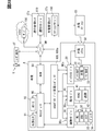
- the energy manager 100 according to the first embodiment of the present disclosure shown in FIGS. 1 and 2 is mounted on the vehicle A.
- the vehicle A is a BEV (Battery Electric Vehicle) equipped with a main battery 22 for traveling and traveling with the electric power of the main battery 22.
- the energy manager 100 has a function of a battery management device that manages the state of the main battery 22.
- the vehicle A is equipped with a DCM93, a navigation device 60, a user input unit 160, a plurality of consumption domains DEc, a power supply domain DEs, a charging system 50, and the like together with the above-mentioned energy manager 100.
- DCM (Data Communication Module) 93 is a communication module mounted on vehicle A.
- the DCM93 transmits and receives radio waves to and from the base station BS around the vehicle A by wireless communication in accordance with communication standards such as LTE (Long Term Evolution) and 5G.
- LTE Long Term Evolution
- 5G 5th Generationан ⁇ 93
- the DCM93 can send and receive information to and from the cloud server 190, the station manager 180, and the like through the network NW.
- the cloud server 190 is an information distribution server installed on the cloud, and distributes, for example, weather information, traffic jam information, and the like.
- the station manager 180 is an arithmetic system installed in the charge management center CTc.
- the station manager 180 is communicably connected to a large number of charging stations CS installed in a specific area through a network NW.
- the station manager 180 keeps track of station information for each charging station CS.
- the station information includes the installation location of the charging station CS, availability information indicating whether or not the charging station CS is in use, charging capacity information of the charger, and the like.
- the charging capacity information includes, for example, whether or not quick charging is possible, the corresponding charging standard, and the maximum output (kW) of quick charging.
- the charging station CS is an infrastructure facility that charges the main battery 22 for traveling mounted on the vehicle A. Each charging station CS charges the main battery 22 using AC power supplied through the power grid or DC power supplied from a photovoltaic power generation system or the like. Charging station CS is installed in each parking lot such as a shopping mall, a convenience store, and a public facility.
- the navigation device 60 is an in-vehicle device that provides route guidance to a destination set by the user.
- the navigation device 60 guides straight ahead, left / right turn, lane change, etc. at intersections, turnout points, merging points, etc. by displaying a screen and reproducing voice.
- the navigation device 60 can provide the energy manager 100 with information such as a distance to a destination, a vehicle speed in each traveling section, and a height difference as navigation information.
- the user input unit 160 is an operation device that accepts input operations by a user of vehicle A such as a driver.
- the user input unit 160 includes, for example, a user operation for operating the navigation device 60, a user operation for switching between starting and stopping of temperature control (described later), a user operation for changing various setting values related to the vehicle A, and the like. Is entered.
- the user input unit 160 can provide the energy manager 100 with input information based on the user operation.
- a steering switch provided on the spokes of the steering wheel, a switch and dial installed on the center console, and a voice input device for detecting the driver's utterance are mounted on the vehicle A as the user input unit 160.
- the touch panel or the like of the navigation device 60 may function as the user input unit 160.
- a user terminal such as a smartphone or a tablet terminal may function as a user input unit 160 by being connected to the energy manager 100 by wire or wirelessly (for example, Bluetooth, a registered trademark).
- the consumption domain DEc is a group of in-vehicle devices that realize various vehicle functions by using electric power such as the main battery 22.
- a group of in-vehicle devices including at least one domain manager and whose power consumption is controlled by the domain manager is defined as one consumption domain DEc.
- the plurality of consumption domains DEc include a travel control domain and an air conditioning control domain.
- the travel control domain is the consumption domain DEc that controls the travel of the vehicle A.
- the travel control domain includes a motor generator 31, an inverter 32, a steer control system 33, a brake control system 34, and a motion manager 30.
- the motor generator 31 is a drive source that generates a driving force for driving the vehicle A.
- the inverter 32 controls power running and regeneration by the motor generator 31.
- the inverter 32 converts the DC power supplied from the main battery 22 into three-phase AC power and supplies it to the motor generator 31 during power running by the motor generator 31.
- the inverter 32 can adjust the frequency, current, and voltage of AC power, and controls the generated driving force of the motor generator 31.
- the inverter 32 converts AC power into DC power and supplies it to the main battery 22.
- the steering control system 33 controls the steering of the vehicle A.
- the brake control system 34 controls the braking force generated in the vehicle A.
- the motion manager 30 integrally controls the inverter 32, the steering control system 33, and the brake control system 34, and realizes the running of the vehicle A according to the driving operation of the driver.
- the motion manager 30 functions as a domain manager of the travel control domain, and comprehensively manages the power consumption by each of the motor generator 31, the inverter 32, the steering control system 33, and the brake control system 34.
- the air conditioning control domain is a consumption domain DEc that performs air conditioning in the living room space of vehicle A and temperature control of the main battery 22.
- the air conditioning control domain includes an HVAC (Heating, Ventilation, and Air Conditioning) 41, a temperature control system 42, and a heat manager 40.
- HVAC Heating, Ventilation, and Air Conditioning
- a plurality of HVAC 41s may be installed in one vehicle A.
- the HVAC 41 is an electric air conditioner that heats, cools, and ventilates a living room space by using the electric power supplied from the main battery 22.
- the HVAC 41 includes a refrigeration cycle device, a blower fan, an electric heater, an air mix damper, and the like.
- the HVAC 41 can control a compressor, an electric heater, an air mix damper, and the like of a refrigeration cycle device to generate warm air and cold air.
- the HVAC 41 supplies the warm air or cold air generated by the operation of the blower fan to the living room space as air conditioning air.
- the temperature control system 42 is a system that cools or raises the temperature of the main battery 22.
- the temperature control system 42 may cool or raise the temperature of the motor generator 31, the inverter 32, and the like together with the main battery 22.
- the temperature control system 42 keeps the temperature of the electric traveling system within a predetermined temperature range by circulating the coolant heated or cooled by the HVAC 41.
- the temperature control system 42 is composed of a cooling circuit, an electric pump, a radiator, a chiller, a liquid temperature sensor, and the like.
- the cooling circuit is mainly composed of pipes installed so as to go around each configuration of the electric traveling system such as the main battery 22, the motor generator 31, and the inverter 32.
- the electric pump circulates the coolant filled in the piping of the cooling circuit.
- the battery heat transferred to the coolant is released to the outside air by the radiator or released to the refrigerant of the HVAC 41 by the chiller.
- the liquid temperature sensor measures the temperature of the coolant.
- the heat manager 40 is an in-vehicle computer that controls the operation of the HVAC 41 and the temperature control system 42.
- the heat manager 40 compares the set temperature of the air conditioning in the living room space with the measured temperature of the temperature sensor installed in the living room space, and controls the air conditioning operation of the HVAC 41.
- the heat manager 40 controls the temperature control operation of the HVAC 41 and the temperature control system 42 with reference to the measurement result by the liquid temperature sensor.
- the above heat manager 40 functions as a domain manager of the heat domain, and comprehensively manages the power consumption by each of the HVAC 41 and the temperature control system 42.
- the power supply domain DEs are a group of in-vehicle devices for enabling power supply to the consumption domain DEc.
- the power supply domains DEs like the consumption domain DEc, include at least one domain manager.
- the power supply domains DEs include a charging circuit 21, a main battery 22, a sub-battery 23, and a battery manager 20.
- the charging circuit 21 functions as a junction box that integrally controls the flow of electric power between each consumption domain DEc and each of the batteries 22 and 23 in cooperation with the battery manager 20.
- the charging circuit 21 supplies electric power from the main battery 22 and the sub-battery 23, and charges the main battery 22 and the sub-battery 23.
- the main battery 22 is a secondary battery capable of charging and discharging electric power.
- the main battery 22 includes an assembled battery including a large number of battery cells.
- the battery cell is, for example, a nickel metal hydride battery, a lithium ion battery, an all-solid-state battery, or the like.
- the electric power stored in the main battery 22 is mainly used for traveling the vehicle A and air-conditioning the living room space.
- the sub-battery 23 is a secondary battery capable of charging and discharging electric power, like the main battery 22.
- the sub-battery 23 is, for example, a lead storage battery.
- the battery capacity of the sub-battery 23 is less than the battery capacity of the main battery 22.
- the electric power stored in the sub-battery 23 is mainly used by auxiliary machinery and the like of the vehicle A.
- the battery manager 20 is an in-vehicle computer that functions as a domain manager of the power supply domain DEs.
- the battery manager 20 manages the power supplied from the charging circuit 21 to each consumption domain DEc.
- the battery manager 20 notifies the energy manager 100 of the remaining amount information about the main battery 22 and the sub battery 23.
- the charging system 50 supplies electric power to the power supply domain DEs and enables charging of the main battery 22.
- An external charger is electrically connected to the charging system 50 at the charging station CS.
- the charging system 50 outputs the charging power supplied through the charging cable to the charging circuit 21.
- the charging system 50 converts the AC power supplied from the normal charging charger into DC power and supplies it to the charging circuit 21.
- the charging system 50 outputs DC power supplied from the quick charging charger to the charging circuit 21.
- the charging system 50 has a function of communicating with a charger for quick charging, and controls the voltage supplied to the charging circuit 21 in cooperation with the control circuit of the charger.
- the energy manager 100 manages the power usage by each consumption domain DEc in an integrated manner.
- the energy manager 100 is realized by an in-vehicle computer 100a including a processing unit 11, a RAM 12, a storage unit 13, an input / output interface 14, and a bus connecting them.
- the processing unit 11 is hardware for arithmetic processing combined with the RAM 12.
- the processing unit 11 executes various processes for realizing the functions of the functional units described later by accessing the RAM 12.
- the storage unit 13 is configured to include a non-volatile storage medium.
- Various programs (battery management programs, etc.) executed by the processing unit 11 are stored in the storage unit 13.
- the energy manager 100 executes the battery management program stored in the storage unit 13 by the processing unit 11, and includes a plurality of functional units related to the state management of the main battery 22. Specifically, the energy manager 100 includes an external information acquisition unit 71, an internal information acquisition unit 72, a temperature simulation unit 74, and a temperature control control unit 75 as functional units based on the battery management program.
- the power supply to the in-vehicle computer 100a is continued even when the vehicle A is in a non-travelable state (for example, in an ignition off state). Therefore, the energy manager 100 can activate each functional unit and execute a predetermined process if it is necessary to execute the control even in the neglected period described later.
- the external information acquisition unit 71 and the internal information acquisition unit 72 acquire vehicle usage information that affects the state of the main battery 22 at the arrival point of the vehicle A.
- the destination is a parking lot or a waiting area where the vehicle A is left, a charging station CS, or the like.
- the state of the main battery 22 is, for example, the remaining amount, the temperature, and the like.
- the external information acquisition unit 71 acquires information provided from the outside of the vehicle A among the vehicle usage information that affects the state of the main battery 22.
- the external information acquisition unit 71 can acquire center information distributed by, for example, the station manager 180, the cloud server 190, or the like as vehicle usage information.
- the external information acquisition unit 71 acquires the usability information and the charging capacity information regarding the charger of the charging station CS from the station manager 180.
- the external information acquisition unit 71 acquires weather information, traffic congestion information, and the like from the cloud server 190.
- the meteorological information includes information indicating the outside air temperature, the amount of solar radiation, the amount of radiant heat from the road surface, the presence or absence of rainfall or snowfall, etc. on the traveling route set in the navigation device 60.
- the internal information acquisition unit 72 acquires the vehicle usage information generated inside the vehicle A among the vehicle usage information that affects the state of the main battery 22.
- the internal information acquisition unit 72 can acquire vehicle usage information provided by, for example, the navigation device 60, the power supply domain DEs, the consumption domain DEc, and the like.
- the internal information acquisition unit 72 acquires the above-mentioned navigation information from the navigation device 60.
- the navigation information includes information such as the number of traffic lights (number of stops) in addition to the distance to the destination (arrival place), the vehicle speed of each section, and the height difference.
- the internal information acquisition unit 72 acquires status information indicating the status of the power supply domain DEs from the battery manager 20.
- the status information includes remaining amount information, temperature information, and the like of the main battery 22 and the sub battery 23.
- the remaining amount information is, for example, the value of SOC (States Of Charge, the unit is "%").
- the internal information acquisition unit 72 acquires the driving tendency information of the driver driving the vehicle A from the exercise manager 30 as vehicle usage information.
- the driving tendency information is, for example, information indicating the driving tendency of the driver, and is information for predicting a running load.
- the driving tendency information includes at least information indicating the tendency of the driver's accelerator opening and brake pedal effort.
- the internal information acquisition unit 72 acquires input information of a user who uses the vehicle A such as a driver.
- the input information may be information input to the user input unit 160 by a user boarding the vehicle A, or information input by a user outside the vehicle A to a user terminal functioning as the user input unit 160. May be good. Further, the input information may be information input by the user in real time in response to an inquiry from the system side such as the energy manager 100, or may be information indicating a set value recorded by the user's past operation. ..
- the internal information acquisition unit 72 acquires real-time input information from the user input unit 160, and acquires user-set values based on past input information from the storage unit 13 and the like.
- the internal information acquisition unit 72 acquires status information indicating the status of each consumption domain DEc from each domain manager.
- the status information includes information indicating the operating state of each in-vehicle device.
- the internal information acquisition unit 72 acquires the set temperature of the air conditioner in the living room space (hereinafter, “air conditioner request information”) and the air conditioner information indicating the current temperature as status information. Further, the internal information acquisition unit 72 may acquire the temperature information of the coolant of the cooling circuit, the information indicating the state (for example, the current temperature, etc.) of the motor generator 31 and the inverter 32, etc. as the status information.
- the external information acquisition unit 71 and the internal information acquisition unit 72 acquire vehicle usage information, which is a future estimated value, in addition to the vehicle usage information, which is the current actual measurement value. More specifically, the vehicle A can have a future use schedule.
- the usage schedule includes a running schedule after leaving, a running schedule under a high load, a charging schedule, a running schedule after leaving the main battery 22 in a high temperature state, a running schedule after leaving in a low temperature, and the like.
- vehicle usage information is provided for each of the period from the present until the start of the usage schedule, the start of the usage schedule, and the period after the start of the usage schedule. To get.
- the information that affects the state of the main battery 22 before the start of the usage schedule is used as the prior impact information, and the information that affects the state of the main battery 22 at the start of the usage schedule is referred to as the start impact information. To do. Further, the vehicle usage information that affects the state of the main battery 22 after the start of the usage schedule is used as the post-effect information.
- the pre-impact information, start-time impact information and post-impact information are estimated or predicted values.
- the prior impact information is, for example, an estimated value of traffic information such as traveling load, air conditioning load, and congestion information from the present to the destination, and environmental information such as outside air temperature and amount of solar radiation.
- the start-time impact information is, for example, usability information such as the waiting time of the charger at the charging station CS.
- the ex-post impact information includes, for example, charging capacity information of the charger of the charging station CS, traveling load information after departure from the arrival place, and environmental information such as outside air temperature and solar radiation amount.
- the environmental information around the vehicle A acquired as the vehicle usage information can be included in both the pre-impact information and the post-impact information.
- the temperature simulation unit 74 is the target battery temperature Tb of the temperature control controlled for the main battery 22 based on the vehicle usage information acquired by the external information acquisition unit 71 and the internal information acquisition unit 72 (see FIG. 7 and the like). To set. The temperature simulation unit 74 sets an initial value of the target battery temperature Tb, and then repeats updating the target battery temperature Tb so as to reflect the newly acquired vehicle usage information. The temperature simulation unit 74 calculates the initial setting value, for example, when the vehicle A starts running, or when the vehicle A starts parking (leaving).
- the temperature simulation unit 74 calculates the initial setting value of the target battery temperature Tb by referring to the environmental information such as the outside air temperature and the amount of solar radiation, the remaining amount information and temperature information of the main battery 22, and the air conditioning information of the HVAC 41.
- the temperature simulation unit 74 initially sets the target battery temperature based on the new information acquired by the external information acquisition unit 71 and the internal information acquisition unit 72 among the pre-effect information, the start time effect information, and the post-effect information. Change from the value and update from time to time.
- the temperature simulation unit 74 has an execution determination unit 74a and a behavior learning unit 74b as sub-functional units.
- the implementation determination unit 74a determines whether or not to implement the temperature control control of the main battery 22.
- the implementation determination unit 74a refers to the remaining amount information of the main battery 22 acquired by the internal information acquisition unit 72, and determines that the temperature control is not necessary based on the decrease in the remaining amount of the main battery 22. For example, when the predicted value of the remaining battery level at the start or end of the above-mentioned usage schedule is lower than the predetermined remaining amount threshold value, the execution determination unit 74a determines not to execute the temperature control control. In addition, the execution determination unit 74a executes or does not execute the temperature control control of the main battery 22 based on the user's input information acquired by the internal information acquisition unit 72 by the input information acquisition process (see FIG. 6). decide.
- the behavior learning unit 74b learns the behavior tendency of the user who uses the vehicle A. Based on the behavior tendency of the user learned by the behavior learning unit 74b, the temperature simulation unit 74 predicts the use of the vehicle A. Specifically, the temperature simulation unit 74 can set the next travel start time and the like by reflecting the usage prediction based on the behavior tendency.
- the next driving start time is information included in the vehicle usage information as driver information (see FIG. 5).
- the temperature control unit 75 cooperates with the heat manager 40 to execute the temperature control of the main battery 22 determined by the temperature simulation unit 74.
- the temperature control unit 75 sets the distribution between the air conditioning capacity of the HVAC 41 and the temperature control capacity allocated to the temperature control system 42 based on the control command acquired from the temperature simulation unit 74, and achieves both air conditioning control and temperature control. Let me. In this way, the temperature control unit 75 cooperates with the temperature simulation unit 74 to arbitrate between the air conditioning capacity used for air conditioning of the living room space and the temperature control capacity used for temperature control of the main battery 22.
- the temperature simulation unit 74 grasps the upper limit of the refrigerating cycle capacity of the refrigerating cycle device of the HVAC 41.
- the temperature simulation unit 74 sets a temperature control control schedule, in other words, a control pattern for temperature control control, so that the total of the air conditioning requirement amount and the cooling request amount CP, which will be described later, does not exceed the refrigeration cycle capacity amount.
- FIGS. 1 to 6 show a list of a plurality of scenes for which read-ahead control is performed.
- FIG. 5 shows a list of vehicle usage information used for the look-ahead control in each scene in which the look-ahead control is performed.
- FIG. 6 shows an input information acquisition process executed as a sub-process of the look-ahead control process.
- the content of the input information acquired from the user input unit 160 is determined.
- the process proceeds from S22 to S27.
- S27 it is decided to carry out the temperature control control.
- the process proceeds from S22 to S28.
- S28 it is decided not to carry out the temperature control. Further, if there is no input operation by the user in response to the inquiry by the vehicle-mounted interface, the process proceeds from S22 to S23.
- the user terminal is used to further inquire whether to execute or cancel the temperature control.
- the user who possesses the user terminal used for inquiries may be on board the vehicle A or may be out of the vehicle. Also in this case, after the inquiry to the user, the acquisition of the input information transmitted from the user terminal based on the user operation is waited for a predetermined time.
- the content of the input information acquired from the user terminal is determined.
- the process proceeds from S24 to S27 to determine the execution of the temperature control control.
- the process proceeds from S24 to S28, and it is determined not to carry out the temperature control control. If there is no input operation by the user in response to the inquiry from the user terminal, the process proceeds from S24 to S25.
- the user-set information preset by the user is referred to.
- the user can register the above-mentioned user settings by inputting to the menu screen displayed on the navigation device 60 and the user terminal.
- S26 it is determined whether or not there is a user setting for canceling the temperature control control. If there is no user setting to cancel the temperature control, the process proceeds from S26 to S27 to determine the implementation of the temperature control. On the other hand, if there is a user U setting for canceling the temperature control, the process proceeds from S26 to S28, and it is determined not to perform the temperature control.
- Inquiries using the in-vehicle interface may be omitted in situations where the user is absent in the vehicle (for example, scenes 1 and 5 described later). Further, the inquiry using the user terminal may be omitted if the specific user terminal registered in the energy manager 100 does not exist. Further, it may be possible to set the user so as not to make an inquiry using the user terminal.
- ⁇ Scene 1 Before running (while left unattended)>
- scene 1 see TC1 in FIG. 3
- the energy manager 100 performs the look-ahead control shown in detail in FIGS. 7 to 9 to cool the main battery 22 before traveling. Cooling based on look-ahead control in scene 1 (hereinafter, "look-ahead cooling”) can exert effects such as improvement of drivability after running, improvement of electricity cost, removal of regenerative power, and suppression of deterioration of the main battery 22. ..
- the electric power used for the look-ahead cooling may be the electric power supplied by the external power source connected to the vehicle A. In this case, it is possible to suppress the consumption of the electric power stored in the main battery 22.
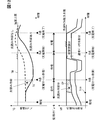
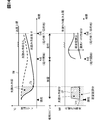
- the temperature simulation unit 74 predicts the time when the next travel starts based on the learning data of the user's usage tendency learned by the behavior learning unit 74b, and uses this travel start time (see point A in FIG. 7) as the vehicle. Get as information. As described above, the temperature simulation unit 74 sets the neglected schedule until the running start time and the running schedule after the running start time in relation to the usage schedule (see the middle stage of FIG. 7). The destination in this travel schedule corresponds to the destination.
- Vehicle usage information such as navigation information, center information, and driver information is used for pre-reading cooling of scene 1 (see FIG. 5, TC1 column).
- vehicle usage information information such as navigation information, traffic congestion information, accelerator opening, and brake pedal effort is used as prediction information (posterior impact information) during traveling.
- environmental information such as outside air temperature, amount of solar radiation, and amount of radiant heat is used as forecast information (pre-effect information and post-effect information) after the present.
- the above-mentioned running start time is used as prediction information (preliminary influence information) from the present to the start of running. Based on these vehicle usage information and the above usage schedule, the energy manager 100 repeatedly executes the look-ahead control process shown in FIG.
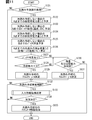
- S101 of the look-ahead control process in the scene 1 it is determined whether or not it is the execution cycle of the look-ahead prediction process. If it is determined in S101 that the execution cycle of the look-ahead prediction process is applicable, the process proceeds to S102. On the other hand, if it is determined that the execution cycle of the look-ahead prediction does not apply, the process proceeds to S112.
- S102 the total amount of power used up to the running start time (see point A in FIG. 7) when the look-ahead cooling is not performed is predicted, and the process proceeds to S103.
- vehicle usage information such as travel start time, outside air temperature, amount of solar radiation, and amount of radiant heat is used for calculating the total amount of electric power used.
- S102 may be omitted.
- S103 based on the total electric energy used calculated in S102, the state of the main battery 22 at the start time of running is predicted when the look-ahead cooling is not performed, and the process proceeds to S104.
- S103 the predicted values of the temperature and the remaining amount (SOC) of the main battery 22 are calculated (see the broken line from the present to the point A in FIG. 7).
- the total amount of power used up to the end time of running (see point O in FIG. 7) when the look-ahead cooling is not performed is predicted, and the process proceeds to S105.
- the total power consumption is calculated by using all the vehicle usage information except the running start time among the vehicle usage information (see FIG. 5 TC1 column) to be used in the scene 1.
- the cooling request amount CP (unit is “J”) and the target battery temperature Tb (unit is “° C.”) in the look-ahead cooling performed by the running start time. ) Is set, and the process proceeds to S107.
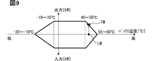
- the maximum power load LM (unit: “kW”) scheduled to be used in the travel schedule is applied to the correlation between the preset battery temperature and the input / output upper limit (see FIG. 9).
- the temperature upper limit TM of the main battery 22 is set.
- the cooling request amount CP (see the area in the shaded area in the lower row of FIG. 7) is calculated so that the battery temperature during running does not exceed the temperature upper limit TM.
- the necessity of pre-reading cooling is determined based on the remaining amount of the main battery 22.
- the remaining battery level at the end time of traveling when the look-ahead cooling is performed is predicted. If the predicted remaining amount is equal to or less than the predetermined remaining amount threshold value in S107, it is determined that the remaining battery level is insufficient, and the process proceeds to S110. On the other hand, in S107, when the predicted remaining amount exceeds the remaining amount threshold value, it is determined that the remaining amount of the battery is not insufficient, and the process proceeds to S108.
- the sum of the air conditioning requirement amount (unit is "J") of the living room space based on the air conditioning request information and the cooling request amount CP of the look-ahead cooling set in S106 is the refrigeration cycle capacity amount of HVAC41 (unit is "J"). It is determined whether or not it exceeds "J").
- the sum of the air conditioning required amount and the cooling required amount CP exceeds the refrigerating cycle capacity amount, it is determined that the cooling capacity is insufficient, and the process proceeds to S110.
- the sum of the air conditioning required amount and the cooling required amount CP is equal to or less than the refrigerating cycle capacity amount, it is determined that the cooling capacity is not insufficient, and the process proceeds to S109.
- the time schedule for pre-reading cooling is determined, and the process proceeds to S112.
- the air conditioning capacity used for cooling the living room space and the temperature control capacity used for look-ahead cooling are arbitrated, and the amount of look-ahead cooling performed (unit: “kW”) and the temperature control start time tcs are set.
- the amount of look-ahead cooling performed is set to a value corresponding to the difference between the maximum point of compressor efficiency in the refrigeration cycle device and the cooling capacity used for living room air conditioning.
- the time preceding the running start time by the time (sec) obtained by dividing the cooling request amount CP (J) by the pre-reading cooling amount (kW) is set as the temperature control start time tcs.
- the presence or absence of insufficient battery remaining amount and cooling capacity is re-determined as in S107 and S108. If it is determined in S110 that the remaining battery level at the end time of travel is equal to or less than the remaining amount threshold value even if the cooling request amount CP is reduced, the look-ahead control process is terminated. Similarly, if it is determined in S110 that the upper limit of the cooling capacity is exceeded even if the cooling request amount CP is reduced, the look-ahead control process is terminated.
- S110 determines whether the remaining battery level nor the cooling capacity is insufficient due to the reduction of the cooling required amount CP. If it is determined in S110 that neither the remaining battery level nor the cooling capacity is insufficient due to the reduction of the cooling required amount CP, the process proceeds to S111.
- S111 the time schedule for cooling execution is determined by the same method as in S109 so as to satisfy the cooling request amount CP reduced in S110, and the process proceeds to S112. It should be noted that S108 to S111 are processes for arbitrating the air conditioning capacity and the temperature control capacity in a broad sense.
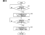
- the temperature control start time tcs set in S109 or S111 is compared with the current time, and it is determined whether or not the pre-reading cooling implementation period has been reached. If it is determined in S112 that the pre-reading cooling is not performed, the pre-reading control process is terminated. On the other hand, if it is determined that the look-ahead cooling is performed, the process proceeds to S113.
- S114 it is determined whether or not to shift to S115 based on the decision result of implementation and non-execution by the input information acquisition process of S113. If it is determined in the input information acquisition process that the temperature control is not performed, the look-ahead control process is terminated. On the other hand, when it is decided to carry out the temperature control in the input information acquisition process, the process proceeds from S114 to S115.
- the drive instruction of the actuator is output to the heat manager 40 so that the main battery 22 is cooled, and the look-ahead control process is completed. To do. With S115, the thermal manager 40 starts battery cooling towards the target battery temperature Tb.
- scene 2 (see TC2 in FIGS. 3 and 4), the vehicle A is in a running state.
- the energy manager 100 performs look-ahead control, which is described in detail in FIGS. 10 and 11, to cool the main battery 22 before traveling.
- the look-ahead cooling in the scene 2 can exert effects such as improvement of drivability during high-load driving and suppression of deterioration of the main battery 22.
- the temperature simulation unit 74 determines the start time of the high-load traveling section (see point A in FIG. 10), the end time of the high-load traveling section (see point B in FIG. 10), and the arrival time at the destination (FIG. 10). 10 Refer to point O). Further, the temperature simulation unit 74 sets a normal traveling schedule and a traveling schedule with a high load in relation to the usage schedule (see the middle stage of FIG. 10). The destination in these travel schedules corresponds to the destination.
- Vehicle usage information such as navigation information, center information, and driver information is used for pre-reading cooling of scene 2 (see FIG. 5, TC2 column).
- scene 2 all the vehicle usage information to be used is used for the look-ahead control as the prediction information (pre-impact information and post-impact information) after the present.
- the energy manager 100 Based on these vehicle usage information and the above usage schedule, the energy manager 100 repeatedly executes the look-ahead control process shown in FIG.
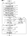
- S121 of the look-ahead control process in the scene 2 it is determined whether or not it is the execution cycle of the look-ahead prediction process. If it is determined in S121 that the execution cycle of the look-ahead prediction process is applicable, the process proceeds to S122. On the other hand, if it is determined that the execution cycle of the look-ahead prediction does not apply, the process proceeds to S132.
- S122 the total amount of power used up to the start time of the high-load traveling section (see point A in FIG. 10) when the look-ahead cooling is not performed is predicted, and the process proceeds to S123.
- all vehicle usage information see FIG. 5, TC2 column) to be used in scene 2 is used for calculating the total power consumption.
- S123 based on the total electric energy used calculated in S122, the state of the main battery 22 at the start time of the high-load traveling section when the look-ahead cooling is not performed is predicted, and the process proceeds to S124.
- the predicted values of the temperature and the remaining amount (SOC) of the main battery 22 are calculated (see the broken line from the present to the point A in FIG. 10).
- S124 the total amount of power used up to the end time of the arrival time of the destination is predicted when the look-ahead cooling is not performed, and the process proceeds to S125.
- S124 as well, as in S122, all vehicle usage information (see FIG. 5, TC2 column) to be used in scene 2 is used for calculating the total power consumption.
- the cooling request amount CP (unit is “J”) and the target battery temperature Tb in the look-ahead cooling to be performed by the start time of the high load running are set. ..
- the maximum power load LM (unit: “kW”) to be used in high-load driving is applied to the correlation between the preset battery temperature and the input / output upper limit (see FIG. 9).
- the cooling request amount CP (see the area in the shaded area in the lower part of FIG. 10) is calculated so that the battery temperature during high-load running does not exceed the temperature upper limit TM.
- S127 the necessity of pre-reading cooling is determined based on the remaining amount of the main battery 22.
- the remaining battery level at the time of arrival at the destination when the look-ahead cooling is performed is predicted. If the predicted remaining amount is equal to or less than the remaining amount threshold value in S127, it is determined that the remaining amount of the battery is insufficient, and the process proceeds to S130. On the other hand, in S127, when the predicted remaining amount exceeds the remaining amount threshold value, it is determined that the remaining amount of the battery is not insufficient, and the process proceeds to S128.
- the sum of the air conditioning requirement amount (unit is "J") of the living room space based on the air conditioning request information and the cooling request amount CP of the look-ahead cooling set in S126 is the refrigeration cycle capacity amount of HVAC41 (unit is "J"). It is determined whether or not it exceeds "J"). If the sum of the air conditioning required amount and the cooling required amount CP exceeds the refrigerating cycle capacity amount in S128, it is determined that the cooling capacity is insufficient, and the process proceeds to S130. On the other hand, if it is determined in S128 that the sum of the air conditioning required amount and the cooling required amount CP is equal to or less than the refrigeration cycle capacity amount, it is determined that the cooling capacity is not insufficient, and the process proceeds to S129.
- the time schedule for pre-reading cooling is determined, and the process proceeds to S132.
- the air conditioning capacity used for cooling the living room space and the temperature control capacity used for the look-ahead cooling are arbitrated, and the amount of the look-ahead cooling performed (unit: “kW”) and the temperature control start time tcs are set.
- the amount of pre-reading cooling performed is set to a value corresponding to the difference between the capacity upper limit of the refrigeration cycle device and the cooling capacity used for living room air conditioning.
- the time preceded from the start of the high-load traveling section by the time (sec) obtained by dividing the cooling request amount CP (J) by the pre-reading cooling amount (kW) is defined as the temperature control start time tcs.
- the presence or absence of insufficient battery remaining amount and cooling capacity is re-determined as in S127 and S128. If it is determined in S130 that the remaining battery level at the time of arrival at the destination is equal to or less than the remaining amount threshold value even if the cooling request amount CP is reduced, the look-ahead control process is terminated. Similarly, if it is determined in S130 that the sum of the air conditioning required amount and the cooling required amount CP exceeds the refrigerating cycle capacity amount even if the cooling required amount CP is reduced, the look-ahead control process is terminated.
- S131 the time schedule for cooling is determined by the same method as in S129 so as to satisfy the cooling request amount CP reduced in S130, and the process proceeds to S132. It should be noted that S128 to S131 are processes for arbitrating the air conditioning capacity and the temperature control capacity in a broad sense.
- the temperature control start time tcs set in S129 or S131 is compared with the current time, and it is determined whether or not the pre-reading cooling is performed. If it is determined in S132 that the pre-reading cooling is not performed, the pre-reading control process is terminated. On the other hand, if it is determined that the look-ahead cooling is performed, the process proceeds to S133.
- the above-mentioned input information acquisition process (see FIG. 6) is executed, a decision is made whether or not to implement the temperature control control based on the user's input information, and the process proceeds to S134.
- the inquiry using the user terminal (FIG. 6, S23) may be omitted in consideration of the fact that the user (driver) is driving. Further, when it is estimated that the operating load is high, the inquiry using the user input unit 160 (FIG. 6, S21) may be omitted.
- S134 it is determined whether or not to shift to S135 based on the decision result of implementation and non-execution by the input information acquisition process of S133. If it is determined in the input information acquisition process that the temperature control is not performed, the look-ahead control process is terminated. On the other hand, if it is decided to implement the temperature control in the input information acquisition process, the process proceeds from S134 to S135.
- the drive instruction of the actuator is output to the heat manager 40 so that the main battery 22 is cooled in addition to the cooling of the air conditioner in the living room, and the look-ahead control process is completed.
- the thermal manager 40 starts battery cooling towards the target battery temperature Tb.
- ⁇ Scene 3 Before charging (while driving)>
- scene 3 the vehicle A is in a running state and is in a state before charging the main battery 22.
- the energy manager 100 performs read-ahead control as detailed in FIGS. 12 and 13 to cool the main battery 22 before charging.
- the look-ahead cooling in the scene 3 can exert effects such as shortening the charging time by avoiding the input limitation (see FIG. 9) and suppressing deterioration of the main battery 22.
- the charging to be performed may be quick charging or normal charging. Before the start of rapid charging or normal charging, the target battery temperature corresponding to each charging mode is set.
- the temperature simulation unit 74 Based on the navigation information, the availability information of the charging station CS, and the charging capacity information, the temperature simulation unit 74 arrives at the charging station CS (see point A in FIG. 12), starts charging (see point B in FIG. 12), and Set the charging completion time (see point C in Fig. 12). Further, the temperature simulation unit 74 sets a traveling schedule from the present to the arrival time at the charging station CS, a standby schedule from the arrival time to the charging start time, and a charging schedule from the charging start time to the charging completion time (FIG. 12). See middle row). In this case, the charging station CS corresponds to the destination.
- Vehicle usage information such as navigation information, center information, and driver information is used for pre-reading cooling of scene 3 (see FIG. 5, TC3 column).
- vehicle usage information information such as navigation information, traffic congestion information, accelerator opening, and brake pedal effort is used as prediction information (preliminary impact information) during traveling.
- environmental information such as outside air temperature, amount of solar radiation, and amount of radiant heat is used as forecast information (pre-effect information, start-time effect information, and post-effect information) after the present.
- the above-mentioned charging capacity information is used as prediction information (posterior effect information) during charging.
- the above-mentioned usability information is used as prediction information (start time influence information) from the arrival time at the charging station CS to the charging start time.
- the energy manager 100 repeatedly executes the look-ahead control process shown in FIG.
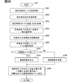
- S141 of the look-ahead control process in the scene 3 it is determined whether or not it is the execution cycle of the look-ahead prediction process. If it is determined in S141 that the execution cycle of the look-ahead prediction process is applicable, the process proceeds to S142. On the other hand, if it is determined that the execution cycle of the look-ahead prediction does not apply, the process proceeds to S152.
- the charging standby time from the arrival time at the charging station CS to the charging start time is predicted based on the charging availability information (see FIG. 5 TC3 column) indicating the waiting time at the charging station CS, and the process proceeds to S143.
- S143 the total amount of power used up to the charging start time (see point B in FIG. 12) when the look-ahead cooling is not performed is predicted, and the process proceeds to S144.
- S143 of all the vehicle usage information (see FIG. 5 TC3 column) targeted for use in scene 3, all the information except the charging availability information and the charging capacity information is used for calculating the total power consumption. Will be done.
- S144 the state of the main battery 22 at the charging start time when the look-ahead cooling is not performed is predicted based on the total power consumption calculated in S143, and the process proceeds to S145.
- S145 the temperature transition of the main battery 22 in the market until the end time of charging is predicted when the look-ahead cooling is not performed (see the broken line in FIG. 12), and the process proceeds to S146.
- the charging capacity information is used as vehicle usage information.
- the cooling request amount CP (unit is “J”) and the target battery temperature Tb in the look-ahead cooling performed by the charging start time are set, and set to S147. move on.
- the cooling request amount CP (see the area in the shaded area in the lower part of FIG. 12) is calculated so that the battery temperature during charging does not exceed the temperature upper limit TM.
- the necessity of pre-reading cooling is determined based on the remaining amount of the main battery 22.
- the remaining amount of the main battery 22 at the time of arrival at the charging station CS is predicted. If the predicted remaining amount is equal to or less than the remaining amount threshold value in S147, it is determined that the remaining amount of the battery is insufficient, and the process proceeds to S150. On the other hand, if the predicted remaining amount exceeds the remaining amount threshold value in S147, it is determined that the remaining amount of the battery is not insufficient, and the process proceeds to S148.
- the sum of the air conditioning requirement amount (unit is "J") of the living room space based on the air conditioning request information and the cooling request amount CP of the look-ahead cooling set in S146 is the refrigeration cycle capacity amount of HVAC41 (unit is "J"). It is determined whether or not it exceeds "J").
- the sum of the air conditioning required amount and the cooling required amount CP exceeds the refrigerating cycle capacity amount, it is determined that the cooling capacity is insufficient, and the process proceeds to S150.
- the sum of the air conditioning required amount and the cooling required amount CP is equal to or less than the refrigerating cycle capacity amount, it is determined that the cooling capacity is not insufficient, and the process proceeds to S149.
- the time schedule for pre-reading cooling is determined, and the process proceeds to S152.
- the air conditioning capacity used for cooling the living room space and the temperature control capacity used for look-ahead cooling are arbitrated, and the amount of look-ahead cooling performed (unit: “kW”) and the temperature control start time tcs are set.
- the amount of pre-reading cooling performed is set to a value corresponding to the difference between the capacity upper limit of the refrigeration cycle device and the cooling capacity used for living room air conditioning.
- the time that precedes the arrival time at the charging station CS by the time (sec) obtained by dividing the cooling request amount CP (J) by the pre-reading cooling amount (kW) is the temperature control start time tcs. Will be done.
- the presence or absence of insufficient battery remaining amount and cooling capacity is re-determined as in S147 and S148. If it is determined in S150 that the remaining battery level at the time of arrival at the charging station CS is equal to or less than the remaining amount threshold value even if the cooling request amount CP is reduced, the look-ahead control process is terminated. Similarly, if it is determined in S150 that the sum of the air conditioning required amount and the cooling required amount CP exceeds the refrigerating cycle capacity amount even if the cooling required amount CP is reduced, the look-ahead control process is terminated.
- S150 determines whether the remaining battery level nor the cooling capacity is insufficient due to the reduction of the cooling required amount CP. If it is determined in S150 that neither the remaining battery level nor the cooling capacity is insufficient due to the reduction of the cooling required amount CP, the process proceeds to S151.
- S151 the time schedule for cooling execution is determined by the same method as in S149 so as to satisfy the cooling request amount CP corrected in S150, and the process proceeds to S152. It should be noted that S148 to S151 are processes for arbitrating the air conditioning capacity and the temperature control capacity in a broad sense.
- the temperature control start time tcs set in S149 or S151 is compared with the current time, and it is determined whether or not the pre-reading cooling is performed. If it is determined in S152 that the pre-reading cooling is not performed, the pre-reading control process is terminated. On the other hand, if it is determined that the look-ahead cooling is performed, the process proceeds to S153.
- the above-mentioned input information acquisition process (see FIG. 6) is executed, a decision is made whether or not to implement the temperature control control based on the user's input information, and the process proceeds to S154.
- the inquiry using the user terminal (FIG. 6, S23) may be omitted in consideration of the fact that the user (driver) is driving.
- S154 it is determined whether or not to shift to S155 based on the decision result of implementation and non-execution by the input information acquisition process of S153. If it is determined in the input information acquisition process that the temperature control is not performed, the look-ahead control process is terminated. On the other hand, if it is decided to carry out the temperature control in the input information acquisition process, the process proceeds from S154 to S155.
- the drive instruction of the actuator is output to the heat manager 40 so that the main battery 22 is cooled in addition to the cooling of the living room air conditioner, and the look-ahead control process is completed.
- the thermal manager 40 starts battery cooling toward the target battery temperature Tb.
- ⁇ Scene 4 At the start of leaving (after charging or running)>
- scene 4 the vehicle A is in a state of being left unattended, and is in a state after charging is completed or after running.
- the energy manager 100 performs read-ahead control as described in detail in FIGS. 14 and 15 to cool the main battery 22 before being left unattended.
- the look-ahead cooling in the scene 4 can exert an effect such as suppressing deterioration of the main battery 22.
- Even when normal charging is performed in parallel with leaving the battery the temperature transition of the main battery 22 during the normal charging period is predicted, and the target battery temperature Tb for cooling the main battery 22 during normal charging is set. May be done.
- Tb may be set. In these cases as well, cooling for the purpose of suppressing deterioration of the main battery 22 becomes possible.
- the temperature simulation unit 74 predicts the time when the next travel starts based on the learning data of the user's usage tendency learned by the behavior learning unit 74b, and uses this travel start time (see point A in FIG. 14) as the vehicle. Get as information. As described above, the temperature simulation unit 74 sets the neglected schedule until the running start time and the running schedule after the running start time in relation to the usage schedule (see the middle stage of FIG. 14).
- center information such as the outside air temperature, the amount of solar radiation and the amount of radiant heat, and vehicle usage information such as the next running start time are used (see FIG. 5, TC4 column).
- vehicle usage information environmental information such as temperature, amount of solar radiation, and amount of radiant heat is used as forecast information (pre-effect information and post-effect information) after the present.
- forecast information pre-effect information and post-effect information
- running start time is used as prediction information (preliminary influence information) from the present to the start of running.
- S161 of the look-ahead control process in the scene 4 it is determined whether or not it is the execution cycle of the look-ahead prediction process. If it is determined in S161 that the execution cycle of the look-ahead prediction process is applicable, the process proceeds to S162. On the other hand, if it is determined that the execution cycle of the look-ahead prediction does not apply, the process proceeds to S172.
- S162 the total amount of power used up to the running start time (see point A in FIG. 14) when the look-ahead cooling is not performed is predicted, and the process proceeds to S163.
- vehicle usage information such as the next travel start time, outside air temperature, solar radiation amount, and radiant heat amount is used for calculating the total power consumption.
- S162 may be omitted.
- the amount of battery deterioration in the market when the look-ahead cooling is not performed is predicted, and the process proceeds to S165.
- the battery deterioration amount calculated in S164 is compared with a predetermined threshold value (reference deterioration amount), and the degree of deterioration progress of the current main battery 22 is evaluated.
- the reference deterioration value is defined by, for example, the correlation between the usage period of the vehicle A and the reference SOH (States Of Health, the unit is "%").
- S164 when the value of SOH indicating the degree of deterioration of the current battery exceeds the SOH of the reference deterioration amount, it is estimated that the deterioration amount is small, and the look-ahead control process is terminated. On the other hand, in S164, when the current SOH value is equal to or less than the reference SOH, it is estimated that the amount of deterioration is large, and the process proceeds to S166.
- the cooling request amount CP (unit is “J”) and the target battery temperature Tb in the look-ahead cooling to be performed by the running start time are set, and the process proceeds to S167.
- the cooling request amount CP (see the area in the shaded area in the lower part of FIG. 14) is calculated so that the battery temperature during leaving is lower than, for example, the outside air temperature.
- S167 the necessity of pre-reading cooling is determined based on the remaining amount of the main battery 22.
- SOC the SOC of the traveling start time when the look-ahead cooling is performed is compared with the SOC (remaining amount threshold value) required for the vehicle A to reach the next joint. If the SOC of the main battery 22 is less than or equal to the SOC required to reach the destination, it is determined that the remaining battery level is insufficient, and the process proceeds to S170. On the other hand, in S167, when the SOC of the main battery 22 exceeds the required SOC, it is determined that the remaining battery level is not insufficient, and the process proceeds to S168.
- the sum of the air conditioning requirement amount (unit is "J") of the living room space based on the air conditioning request information and the cooling request amount CP of the look-ahead cooling set in S166 is the refrigeration cycle capacity amount of HVAC41 (unit is "J"). It is determined whether or not it exceeds "J").
- the sum of the required air conditioning amount and the required cooling amount CP exceeds the refrigerating cycle capacity amount, it is determined that the cooling capacity is insufficient, and the process proceeds to S170.
- the sum of the air conditioning required amount and the cooling required amount CP is equal to or less than the refrigerating cycle capacity amount, it is determined that the cooling capacity is not insufficient, and the process proceeds to S169.
- the time schedule for carrying out look-ahead cooling is determined, and the process proceeds to S172.
- the air conditioning capacity used for cooling the living room space and the temperature control capacity used for the look-ahead cooling are arbitrated, and the amount of the look-ahead cooling performed (unit: “kW”) and the temperature control start time tcs are set.
- the amount of look-ahead cooling performed is set to a value corresponding to the difference between the maximum point of compressor efficiency in the refrigeration cycle device and the cooling capacity used for living room air conditioning.
- the time that precedes the running start time by the time (sec) obtained by dividing the cooling request amount CP (J) by the pre-reading cooling amount (kW) is set as the temperature control start time tcs.
- S170 after multiplying the cooling request amount CP by a predetermined value of less than 1, the presence or absence of insufficient battery remaining amount and cooling capacity is re-determined as in S167 and S168. If it is determined in S170 that the remaining battery level at the end time of travel is equal to or less than the remaining amount threshold value even if the cooling request amount CP is reduced, the look-ahead control process is terminated. Similarly, if it is determined in S170 that the sum of the air conditioning required amount and the cooling required amount CP exceeds the refrigerating cycle capacity amount even if the cooling required amount CP is reduced, the look-ahead control process is terminated.
- S170 determines whether the remaining battery level nor the cooling capacity is insufficient due to the reduction of the cooling required amount CP. If it is determined in S170 that neither the remaining battery level nor the cooling capacity is insufficient due to the reduction of the cooling required amount CP, the process proceeds to S171.
- S171 the time schedule for cooling execution is determined by the same method as in S169 so as to satisfy the cooling request amount CP corrected in S170, and the process proceeds to S172.
- S168 to S171 are processes for arbitrating the air conditioning capacity and the temperature control capacity in a broad sense.
- the temperature control start time tcs set in S169 or S171 is compared with the current time, and it is determined whether or not the pre-reading cooling is performed. If it is determined in S172 that the pre-reading cooling is not performed, the pre-reading control process is terminated. On the other hand, if it is determined that the look-ahead cooling is performed, the process proceeds to S173.
- S173 the above-mentioned input information acquisition process (see FIG. 6) is executed, a decision is made whether or not to implement the temperature control control based on the user's input information, and the process proceeds to S174.
- S174 it is determined whether or not to shift to S175 based on the determination result of implementation and non-execution by the input information acquisition process of S173. If it is determined in the input information acquisition process that the temperature control is not performed, the look-ahead control process is terminated. On the other hand, if it is decided to carry out the temperature control in the input information acquisition process, the process proceeds from S174 to S175.
- the drive instruction of the actuator is output to the heat manager 40 so that the main battery 22 is cooled in addition to the cooling of the living room air conditioner, and the look-ahead control process is completed.
- the thermal manager 40 starts battery cooling toward the target battery temperature Tb.
- ⁇ Scene 5 Before driving (leaving in a low temperature environment)>
- vehicle A is in a state of being left in a low temperature environment.
- the energy manager 100 performs the look-ahead control shown in detail in FIGS. 16 to 18 to raise the temperature of the main battery 22 before traveling.
- the temperature rise of the main battery 22 is carried out by, for example, a heat pump, an electric heater (PTC heater), or the like. More specifically, the heat of the high temperature and high pressure refrigerant after the compressor of the HVAC 41 is transferred to the coolant of the temperature control system 42 via the heat exchanger. Further, the electric heater also raises the temperature of the coolant by the heat generated by the energization. The main battery 22 is heated by the coolant thus heated.
- look-ahead warm-up can exert effects such as improvement of drivability after the start of running, improvement of electricity cost, and removal of regenerative power.
- the power supplied by the external power source connected to the vehicle A may be used for the look-ahead warm-up. In this case, it is possible to suppress the consumption of the electric power stored in the main battery 22.
- the temperature simulation unit 74 predicts the time when the next travel starts based on the learning data of the user's usage tendency learned by the behavior learning unit 74b, and uses this travel start time (see point A in FIG. 16) as the vehicle. Get as information. As described above, the temperature simulation unit 74 sets the neglected schedule until the running start time and the running schedule after the running start time in relation to the usage schedule (see the middle stage of FIG. 16). The destination in this travel schedule corresponds to the destination.
- Vehicle usage information such as navigation information, center information, and driver information is used for the look-ahead warm-up of scene 5 (see FIG. 5, TC5 column).
- vehicle usage information information such as navigation information, traffic congestion information, accelerator opening, and brake pedal effort is used as prediction information (posterior impact information) during traveling.
- environmental information such as outside air temperature, amount of solar radiation, and amount of radiant heat is used as forecast information (pre-effect information and post-effect information) after the present.
- the above-mentioned running start time is used as prediction information (preliminary influence information) from the present to the start of running. Based on these vehicle usage information and the above usage schedule, the energy manager 100 repeatedly executes the look-ahead control process shown in FIG.
- S181 of the look-ahead control process in the scene 5 it is determined whether or not it is the execution cycle of the look-ahead prediction process. If it is determined in S181 that the execution cycle of the look-ahead prediction process is applicable, the process proceeds to S182. On the other hand, if it is determined that the execution cycle of the look-ahead prediction does not apply, the process proceeds to S192.
- S182 the total power consumption up to the running start time (see point A in FIG. 16) when the look-ahead warm-up is not performed is predicted, and the process proceeds to S183.
- vehicle usage information such as travel start time, outside air temperature, amount of solar radiation, and amount of radiant heat is used for calculating the total amount of electric power used.
- S182 may be omitted.
- the total amount of power used up to the end time of running (see point O in FIG. 16) when the look-ahead warm-up is not performed is predicted, and the process proceeds to S185.
- the total power consumption is calculated by using all the vehicle usage information except the running start time among the vehicle usage information (see FIG. 5 TC5 column) to be used in the scene 5.
- the warm-up requirement HP (unit is "J") and the target battery temperature Tb in the look-ahead warm-up to be carried out by the running start time are set. Proceed to S187.
- the maximum power load LM to be used in the travel schedule is applied to the correlation between the preset battery temperature and the input / output upper limit (see FIG. 18), and the temperature upper limit TM of the main battery 22 is applied. And the temperature lower limit TL is set.
- the warm-up request amount HP is calculated so that the battery temperature during running is maintained between the temperature upper limit TM and the temperature lower limit TL.
- S187 the remaining amount of the main battery 22 at the end time of running when the look-ahead warm-up is performed is predicted. If the predicted remaining amount is equal to or less than the predetermined remaining amount threshold value in S187, it is determined that the remaining battery level is insufficient, and the process proceeds to S190. On the other hand, in S187, when the predicted remaining amount exceeds the remaining amount threshold value, it is determined that the remaining amount of the battery is not insufficient, and the process proceeds to S188.
- the sum of the air-conditioning requirement amount (unit is "J") of the living room space based on the air-conditioning request information and the warm-up request amount HP of the look-ahead warm-up set in S186 is the heating capacity amount (unit) of HVAC41 or the like. Determines whether or not it exceeds "J").
- the sum of the air conditioning required amount and the warming required amount HP exceeds the heating capacity amount, it is determined that the heating capacity is insufficient, and the process proceeds to S190.
- the sum of the air conditioning required amount and the warming required amount HP is equal to or less than the heating capacity amount, it is determined that the heating capacity is not insufficient, and the process proceeds to S189.
- the time schedule for carrying out the look-ahead warm-up is determined, and the process proceeds to S192.
- the air conditioning capacity used for heating the living room space and the temperature control capacity used for the look-ahead warm-up are arbitrated, and the amount of the look-ahead warm-up performed (unit is “kW”) and the temperature control start time tcs are set. ..
- the time that precedes the running start time by the time (sec) obtained by dividing the warm-up request amount HP (J) by the read-ahead warm-up execution amount (kW) is set as the temperature control start time tcs.
- S190 after multiplying the warm-up request amount HP by a predetermined value of less than 1, the presence or absence of insufficient battery remaining amount and heating capacity is re-determined as in S187 and S188. If it is determined in S190 that the remaining battery level at the end time of travel is equal to or less than the remaining amount threshold value even if the warm-up request amount HP is reduced, the look-ahead control process is terminated. Similarly, if it is determined in S190 that the sum of the air conditioning required amount and the warming required amount HP exceeds the heating capacity even if the warm-up required amount HP is reduced, the look-ahead control process is terminated.
- S190 determines whether the remaining battery level nor the heating capacity is insufficient due to the reduction of the warm-up request amount HP. If it is determined in S190 that neither the remaining battery level nor the heating capacity is insufficient due to the reduction of the warm-up request amount HP, the process proceeds to S191.
- S191 the time schedule for warm-up execution is determined by the same method as in S189 so as to satisfy the warm-up request amount HP corrected in S190, and the process proceeds to S192.
- S188 to S191 are processes for arbitrating the air conditioning capacity and the temperature control capacity.
- the temperature control start time ths set in S189 or S191 is compared with the current time, and it is determined whether or not the pre-reading warm-up period has come. If it is determined in S192 that the pre-reading warm-up period is not in effect, the pre-reading control process is terminated. On the other hand, if it is determined that the read-ahead warm-up period is in effect, the process proceeds to S193.
- the above-mentioned input information acquisition process (see FIG. 6) is performed, a decision is made to implement or not implement the temperature control control based on the user's input information, and the process proceeds to S194.
- the inquiry using the user input unit 160 in the vehicle (FIG. 6, S21) may be omitted.
- the inquiry using the user terminal (FIG. 6, S23) may be omitted in a time zone such as midnight or early morning.
- S194 it is determined whether or not to shift to S195 based on the decision result of implementation and non-execution by the input information acquisition process of S193. If it is determined in the input information acquisition process that the temperature control is not performed, the look-ahead control process is terminated. On the other hand, if it is decided to implement the temperature control in the input information acquisition process, the process proceeds from S194 to S195.
- the actuator drive instruction is output to the heat manager 40 so that the temperature of the main battery 22 is raised, and the look-ahead control process is performed. finish.
- the heat manager 40 starts battery warm-up toward the target battery temperature Tb.
- the energy manager 100 has determined the necessity of temperature control based on the future prediction of the temperature transition of the main battery 22. In addition to the automatic temperature control based on the judgment of the system side, the energy manager 100 can perform the temperature control based on the user judgment. Further, the energy manager 100 can stop the temperature control control started by the judgment of the system side based on the judgment of the user.
- the manual operation process shown in FIG. 19 is started by the execution determination unit 74a, the temperature control control unit 75, and the like after the start of power supply to the energy manager 100, and is repeatedly executed in a predetermined cycle until the power supply is stopped. To.
- S31 of the manual operation process it is determined whether or not there is a user operation instructing the execution of the temperature control control.
- the user can input a user operation instructing execution and stop of the temperature control control to the user input unit 160. More specifically, an operation screen for inputting execution and stop of temperature control control is displayed on the display of the navigation device 60 or the user terminal that functions as the user input unit 160. The operation of tapping the operation button (icon) displayed on the operation screen is the user operation for instructing the execution of the temperature control control. If the user operation is accepted by using the user terminal capable of wireless communication with the energy manager 100, the user can instruct the execution of the temperature control control from outside the vehicle.
- S33 it is determined whether or not there is a user operation (hereinafter, stop operation) instructing the stop of the temperature control control. If it is determined in S33 that there is no input for the stop operation, the determination in S33 is repeated. As a result, the execution determination unit 74a is in a state of waiting for the stop operation by the user. At this time, the temperature control unit 75 continues the temperature control during execution. Even if the temperature control control is started at the discretion of the system side, the manual operation process can transition to the state of waiting for the stop operation by repeating the determination of S33.
- stop operation a user operation instructing the stop of the temperature control control control.
- the target battery temperature Tb of the temperature control controlled for the main battery 22 is set from the set initial value based on the vehicle usage information that affects the state of the main battery 22 at the destination. Be changed. Based on the above, the target battery temperature Tb can be updated to an appropriate value at any time based on the new vehicle usage information. Therefore, it is possible to reduce the excess or deficiency of the temperature adjustment of the main battery 22.
- At least one of prior impact information, start impact information, and post impact information is acquired as vehicle usage information. Based on the above, it becomes easy to secure the accuracy of the estimated value or the predicted value that predicts the state of the main battery 22 in the future. Therefore, the excess or deficiency of the temperature adjustment of the main battery 22 can be further reduced.
- the external information acquisition unit 71 and the internal information acquisition unit 72 of the first embodiment can acquire all of the prior impact information, the start impact information, and the post impact information as vehicle usage information. Then, the temperature simulation unit 74 updates the target battery temperature Tb at any time based on the acquired information among the pre-effect information, the start time effect information, and the post-effect information. According to the above, since the target battery temperature Tb is continuously updated, the excess or deficiency of the temperature adjustment of the main battery 22 is likely to be reduced.
- the environmental information around the vehicle A is acquired as the vehicle usage information, and the target battery temperature Tb is changed based on the environmental information. According to the above, even if the outside air temperature, the amount of solar radiation, the amount of radiant heat, etc. around the vehicle A change, the accuracy of predicting the state of the main battery 22 can be maintained high. Therefore, the temperature control of the main battery 22 with reduced waste and shortage is realized.
- the driver's driving tendency information specifically, the accelerator opening and the brake pedal effort, etc. are acquired as vehicle usage information, and the target battery temperature Tb considers the variation in the traveling load based on the driving tendency. And can be set.
- the accuracy of predicting the state of the main battery 22 can be maintained even higher even in the manually driven vehicle. Therefore, it becomes easier to realize just enough temperature control control.
- the implementation determination unit 74a determines whether to implement the temperature control control or not. Therefore, the energy manager 100 can control the temperature control of the main battery 22 only at an appropriate timing. In other words, the implementation of temperature control at improper timing can be avoided.
- the embodiment determination unit 74a of the first embodiment determines whether or not to implement the temperature control control based on the decrease in the remaining amount of the main battery 22. Specifically, the remaining amount of the main battery 22 at a predetermined time is predicted, and when the predicted remaining amount falls below the remaining amount threshold value, the temperature control control is stopped. Based on the above, the situation in which the vehicle A is out of power due to the power consumption associated with the temperature control can be appropriately avoided.
- the implementation determination unit 74a of the first embodiment determines whether or not to implement the temperature control control based on the user input information related to the temperature control control. That is, the user's intention is prioritized over the judgment on the system side in determining whether to implement the temperature control control or not. According to the above, when the future action schedule is suddenly changed, the user can cancel the implementation of the temperature control control proposed by the system side with a simple operation. As a result, the convenience of the user related to the temperature control is easily ensured.
- the embodiment determination unit 74a of the first embodiment can manually forcibly start the temperature control of the main battery 22 based on the execution operation of the user.
- the execution determination unit 74a can manually stop the temperature control control during execution based on the stop operation of the user. According to the above, even if the future action schedule changes frequently, the user can easily manage the implementation and non-execution of the temperature control according to the changed action schedule. As a result, the convenience of the user related to the temperature control is further improved.
- the internal information acquisition unit 72 acquires air conditioning request information regarding air conditioning in the living room space.
- the temperature control unit 75 cooperates with the temperature simulation unit 74 to arbitrate the air conditioning capacity used for air conditioning of the living room space and the temperature control capacity used for temperature control of the battery. According to the above, even if the look-ahead control for the main battery 22 is implemented, the comfort of the living space, the function of suppressing window fogging, and the like are not easily impaired. As a result, it becomes possible to make the most effective use of electric power in the entire moving vehicle A including the occupants.
- the temperature simulation unit 74 sets the target battery temperature Tb for cooling the main battery 22 and causes the vehicle A to perform look-ahead cooling before the vehicle A starts traveling. Based on the above, it is possible to ensure drivability after the start of traveling and efficiently recover the regenerative power to the main battery 22. Further, if the look-ahead cooling is carried out by an external electric power, the improvement of the electric power cost during traveling can be realized.
- the temperature transition of the main battery 22 after the start of leaving the vehicle A is predicted (see FIG. 14). Then, the temperature simulation unit 74 sets the target battery temperature Tb for cooling the main battery 22 after the vehicle A starts to be left unattended, and causes pre-reading cooling to be performed. Other than that, the temperature simulation unit 74 sets the target battery temperature Tb for cooling the main battery 22 and causes the pre-reading cooling to be performed even during the running before the start of the normal charging and during the normal charging. Based on the above, it is possible to suppress the cumulative deterioration of the main battery 22 due to exposure to a high temperature.
- the behavior learning unit 74b of the first embodiment learns the behavior tendency of the user who uses the vehicle A. Then, the temperature simulation unit 74 reflects the usage prediction based on the learned behavior tendency, and the duration of neglect or the running start time, and by extension, the temperature control start time tcs of the look-ahead cooling and the temperature control start time ths of the look-ahead warm-up. Can be set. According to the above, even if the next running start time is not set by the user's input operation, the energy manager 100 over-controls the temperature control of the main battery 22 at the timing when the user starts using the vehicle A. It can be completed without any shortage. The next running start time may be set by a user input operation, or may be set with reference to the user's schedule data.
- the temperature simulation unit 74 sets the target battery temperature Tb for cooling the main battery 22 prior to the increase in the traveling load in the high negative traveling section, and causes the pre-reading cooling to be performed. According to the above, it is possible to obtain the effects of ensuring drivability during high-load driving and suppressing deterioration of the main battery 22 by avoiding the output limitation on the high temperature side.
- the temperature simulation unit 74 sets the target battery temperature Tb for cooling the main battery 22 and causes the pre-reading cooling to be performed before the start of charging at the charging station CS. According to the above, it is possible to appropriately complete the temperature control of the main battery 22 at the timing when the user starts using the vehicle A. As a result, effects such as shortening the charging time by avoiding the input restriction and suppressing deterioration of the main battery 22 can be obtained.
- the availability information of the charger at the charging station CS is acquired as vehicle usage information.
- the temperature simulation unit 74 sets the target battery temperature Tb for pre-reading cooling in anticipation of the standby time at the charging station CS when charging cannot be started immediately after arrival based on the usability information.
- the temperature simulation unit 74 recognizes whether or not the charger at the destination can be used, and if the charger cannot be used immediately after arrival, decides to stop or suppress the look-ahead cooling. Therefore, the wasted power input to the look-ahead cooling can be reduced while moving to the charging station CS.
- the charging capacity information of the charger at the charging station CS is acquired as vehicle usage information.
- the temperature simulation unit 74 sets the target battery temperature Tb in the look-ahead cooling based on the charging capacity information.
- the larger the charging capacity (wattage) of the charger the larger the temperature rise during charging, and conversely, the smaller the charging capacity, the smaller the temperature rise. Therefore, according to the grasp of the charging capacity, the excess or deficiency of the temperature adjustment of the main battery 22 due to the look-ahead cooling can be appropriately reduced.
- the effect of look-ahead cooling on traveling and air conditioning in the period until arrival at the charging station CS can be appropriately reduced.
- the temperature simulation unit 74 takes the charging capacity of the charger (for example, 3 kW or 5 kW, etc.) as an input, and stores in advance a calculation formula or a look-up table for determining the target battery temperature Tb.
- the temperature simulation unit 74 sets the target battery temperature Tb for raising the temperature of the main battery 22 before the vehicle A starts traveling, and causes the look-ahead warm-up to be performed. Based on the above, it is possible to obtain effects such as ensuring drivability during traveling by avoiding the output limitation on the low temperature side and efficiently recovering the regenerative power to the main battery 22. Further, if the look-ahead warm-up is carried out by external electric power, improvement of electric power cost during traveling can be realized.
- the processing unit 11 corresponds to the "processor”
- the main battery 22 corresponds to the "battery”
- the charging station CS corresponds to the "charging facility”.
- the in-vehicle computer 100a corresponds to the "computer”
- the energy manager 100 or the in-vehicle computer 100a corresponds to the "battery management device”.
- the external information acquisition unit 71 and the internal information acquisition unit 72 correspond to the "information acquisition unit”
- the temperature simulation unit 74 corresponds to the "target setting unit”
- the temperature control control unit 75 corresponds to the "capacity mediation unit”.
- the target battery temperature Tb corresponds to the "target battery temperature”.
- the second embodiment of the present disclosure shown in FIGS. 20 to 26 is a modification of the first embodiment.
- the vehicle A equipped with the energy manager 100 is a service car used in the mobility service system, and is an autonomous driving vehicle capable of autonomously traveling without any driving operation by the driver.
- the mobility service system is constructed by a plurality of vehicles A, a station manager 180, an operation manager 110, and the like.
- the operation of a plurality of vehicles A is managed by the operation manager 110, and the vehicle A provides a moving space to the user U.
- the plurality of vehicles A, the station manager 180, and the operation manager 110 are each connected to the network NW, and can transmit and receive information to and from each other.
- the details of the operation manager 110 and the vehicle A of the second embodiment will be described in order.
- the operation manager 110 is installed in, for example, an operation management center CTo or the like.
- the operation manager 110 manages the allocation of the vehicle A to the user U.
- the operation manager 110 acquires the user information of the user U who wants to use the mobility service for vehicle allocation management.
- the user information includes at least ID information that identifies the user U, a boarding place and a disembarking place of the user U, a scheduled boarding time (scheduled boarding time zone), and the like as information necessary for using the mobility service.
- the user U inputs user information using, for example, a smartphone, a tablet terminal, a personal computer, or the like as the user terminal UT.
- the operation manager 110 formulates an operation plan for each vehicle A based on the acquired user information.
- the operation plan includes information indicating how many users U get on and off at which place on the travel route.
- the operation manager 110 transmits the formulated operation plan to each vehicle A as a vehicle allocation instruction to the user U.
- the operation plan corresponds to the navigation information of the first embodiment, and includes information such as the distance to the destination, the vehicle speed in each traveling section, and the height difference.
- the operation manager 110 is an arithmetic system mainly composed of at least one server device.
- the server device includes a processing unit 111, a RAM 112, a storage unit 113, an input / output interface 114, a bus connecting these, and the like, and operates as an operation manager 110.
- the processing unit 111 is hardware for arithmetic processing combined with the RAM 112.
- the processing unit 111 executes various processes related to vehicle allocation management and the like by accessing the RAM 112.
- the storage unit 113 is configured to include a non-volatile storage medium.
- the storage unit 113 stores various programs executed by the processing unit 111.
- Vehicle A is equipped with an external sensor 91, a locator 92, an AD (Automated Driving) computer 90, and the like as a configuration for enabling autonomous driving.
- the external sensor 91 includes, for example, a camera unit, a rider, a millimeter wave radar, a sonar, and the like.
- the outside world sensor 91 generates object information that detects an object around the vehicle.
- the locator 92 receives positioning signals from a plurality of positioning satellites of the satellite positioning system, and generates position information of the vehicle A based on each received positioning signal.
- the AD computer 90 cooperates with the operation manager 110 to realize autonomous driving of the vehicle A based on the operation plan.
- the AD computer 90 acquires the operation plan transmitted by the operation manager 110 through the DCM93.
- the AD computer 90 recognizes the traveling environment around the vehicle A based on the object information acquired from the external sensor 91, the position information acquired from the locator 92, and the like, and the planned traveling route for traveling the vehicle A according to the operation plan. To generate.
- the AD computer 90 generates a control command based on the planned travel route and sequentially outputs the control command to the exercise manager 30.
- the motion manager 30 integrally controls the inverter 32, the steering control system 33, the brake control system 34, and the like based on the control command acquired from the AD computer 90, and autonomously drives the vehicle A so as to trace the planned travel route. ..
- the main battery 22 mounted on the vehicle A is used to maintain the stability of the system voltage in the power transmission and distribution network. More specifically, in recent years, power from renewable energy power generation such as solar power generation and wind power generation has been supplied to the power transmission and distribution network. The amount of such renewable energy power generation fluctuates greatly depending on the weather conditions. If there is a surplus or shortage of grid power due to an increase or decrease in the amount of power generation, a power outage may occur due to the grid voltage exceeding the permissible range.
- the energy manager 100 acquires a charge request from the system power to the main battery 22 or a power supply request from the main battery 22 to the system power by the external information acquisition unit 271.
- the external information acquisition unit 271 may acquire a charge request and a power supply request from, for example, a cloud server 190 of an electric power company provided on the cloud, and acquire a charge request and a power supply request together with an operation plan from the operation manager 110. May be good.
- the energy manager 100 sets the target battery temperature Tb of the temperature control to be performed on the main battery 22 by the temperature simulation unit 74 based on the charge request or the power supply request acquired by the external information acquisition unit 271.
- Tb of the temperature control to be performed on the main battery 22 by the temperature simulation unit 74 based on the charge request or the power supply request acquired by the external information acquisition unit 271.
- FIGS. 20 and 21 details of the main process and the plurality of sub-processes performed by the energy manager 100 will be described with reference to FIGS. 20 and 21 based on FIGS. 22 to 26. explain.
- the main processing and each sub processing shown in FIGS. 22 to 26 are continuously performed by the energy manager 100 being activated.
- a judgment as to whether or not to receive the cooperation request obtained in S21 is obtained.
- the decision on whether or not to respond to the cooperation request is made by the mobility service operator, the owner of vehicle A, or the like.
- the approval / disapproval determination may be performed according to a preset determination logic. Alternatively, an inquiry may be made to the owner or the like for each request for cooperation, and a decision on whether or not to accept the request may be made based on the input of the owner or the like. If it is determined in S22 that a cooperation request will be received, the process proceeds to S23. On the other hand, if it is determined that the cooperation request is not received, the process proceeds to S25.
- the designated point designated in the cooperation request is set as the destination where the vehicle A is moved, and the process proceeds to S24.
- a specific charging station CS that can be connected to the grid power is designated as a designated point.
- the target electric energy to be received or delivered at the destination is further acquired from the cloud server 190 or the like, and the process proceeds to S25.
- the amount of electric power required for traveling to the destination is calculated by the sub-processing shown in FIG. In the sub-processes S251 to S257 shown in FIG. 23, various vehicle usage information is acquired.
- S251 the battery temperature at the current time is acquired, and the process proceeds to S252.
- S252 the outside air temperature at the current time is acquired, and the process proceeds to S253.
- S253 the coolant temperature (water temperature) of the temperature control system 42 at the current time is acquired, and the process proceeds to S254.
- the mileage from the current location to the arrival location is acquired based on the travel plan acquired from the operation manager 110, and the process proceeds to S255.
- the current estimated time of arrival is acquired while referring to the traffic information and the like, and the process proceeds to S256.
- the outside air temperature coefficient of the current time is acquired based on the outside air temperature acquired in S252, and the process proceeds to S257.
- the driving inefficiency coefficient of the current driver is acquired based on the driver information, and the process proceeds to S258. When the vehicle A autonomously travels to the destination, S257 is omitted.
- the charging capacity at the destination is calculated by the sub-processing shown in FIG. 24.
- S261 of the sub-processing shown in FIG. 24 the availability information of the charging station CS, which is the destination, is acquired, the availability of the charger (for example, the number of free chargers, etc.) is grasped, and the process proceeds to S262.
- the charging capacity information of the empty charger is acquired, the power capacity (unit: "kW") of this charger is grasped, and the process proceeds to S263.
- the power capacity of the empty charger acquired in S262 is set as the charging capacity of the destination, and the process proceeds to S27 of the main process shown in FIG.
- the battery temperature reached at the destination (corresponding to the target battery temperature Tb in FIG. 12) is calculated by the sub-processing shown in FIG.
- the estimated value of the remaining battery level when arriving at the arrival place is calculated, the remaining battery level is acquired as the remaining power amount, and the process proceeds to S272.
- the electric power capacity of the vacant charger is acquired as the charging capacity of the destination, and the process proceeds to S273.
- the outside air temperature coefficient at the current time is acquired by calculation, and the process proceeds to S274.
- the temperature rise coefficient due to charging (unit: “° C./h”) is acquired, and the process proceeds to S276.
- the limiter temperature for quick charging (corresponding to the temperature upper limit TM, see FIG. 12) is acquired from the correlation between the battery temperature and the input / output upper limit (see FIG. 9), and the process proceeds to S277.
- the battery temperature reached at the destination is calculated by a calculation process (see Equation 3) in which the value obtained by multiplying the charging time by the temperature rise coefficient is subtracted from the limiter temperature of the quick charge, and is shown in FIG. Proceed to S28 of the main process.
- Limiter temperature for quick charging [° C]-(Charging time [h] x Temperature rise coefficient [° C / h]) Battery temperature [° C] reached at the destination ... (Equation 3)
- the control pattern of the battery temperature to the destination is calculated by the sub-processing shown in FIG.
- the battery temperature, the outside air temperature, and the coolant temperature at the current time are acquired in order in the same manner as in S251 to S253 (see FIG. 23), and the process proceeds to S284.
- S284 the amount of electric power required for traveling to the destination is acquired by referring to the calculation result of S258 (see FIG. 23), and the process proceeds to S285.
- S285 similarly to S272 (see FIG. 25)
- the charging capacity of the destination is acquired, and the process proceeds to S286.
- S286 the battery temperature reached at the destination is acquired by referring to the calculation result of S277 (see FIG. 25), and the process proceeds to S287.
- S287 it is determined whether the look-ahead temperature control is implemented or not.
- S287 it is determined whether or not the charging capacity of the charger to be used at the destination is higher than the predetermined value X (unit is “kWh”).
- the predetermined value X unit is “kWh”.
- the temperature control control is set to be suspended, and the process proceeds to S290.
- S289 the temperature control is set to be performed, and the process proceeds to S290.
- a temperature control control pattern to the destination (see the solid line in FIG. 12) is set by arithmetic processing that adds the amount of power required for air conditioning to the destination to the amount of power required to travel to the destination. Proceed to S29 of the main process shown in FIG. In S29, the pre-reading cooling of the main battery 22 is performed in cooperation with the temperature control unit 75 and the heat manager 40 according to the control pattern of the temperature control control set in S28.
- the target battery temperature Tb of the temperature control controlled for the main battery 22 is set based on the request for charging the main battery 22 or the request for supplying power from the main battery 22. Therefore, after the main battery 22 is connected to the grid power, charging from the grid power to the main battery 22 or power supply from the main battery 22 to the grid power can be performed without limitation. According to the above, in order to stabilize the system power, it is possible to reduce the excess or deficiency of the temperature adjustment of the main battery 22 even in the scene where the main battery 22 of the vehicle A is used.
- the external information acquisition unit 271 corresponds to the "request acquisition unit".
- the energy manager 100 can set the target battery temperature Tb if at least one of these pieces of information can be obtained. Further, the type of vehicle usage information used for setting the target battery temperature Tb may be changed as appropriate. For example, environmental information and driving tendency information may not be acquired. In addition, the availability information and charging capacity information of the charging station CS may not be acquired.
- vehicle usage information such as navigation information, center information, and driver information does not have to be obtained from the information sources described in the above embodiments, and is derived from the most desirable information source in each era regardless of the server side or the edge side. May be obtained.
- the station manager 180 and / and the navigation device 60 may be the information source of the charging capacity information.
- the temperature control is stopped based on the decrease in the remaining amount of the main battery 22. It is not necessary to carry out such determination of necessity of temperature control. Further, the temperature control may be stopped under conditions other than the decrease in the remaining battery level. Further, the arbitration between the air conditioning capacity and the temperature control capacity does not have to be carried out. For example, the air conditioning of the living room space may always be prioritized, or the temperature control of the main battery 22 may always be prioritized.
- an independent cooling circuit for cooling the main battery 22 is formed by the temperature control system 42.
- the specific temperature control configuration for cooling the main battery 22 is not limited to the water-cooled configuration as described above, and may be appropriately changed.
- an air-cooled temperature control configuration is adopted.
- the main battery 22 is cooled by the air inside the vehicle, the air cooled by the battery-dedicated air conditioner, the air introduced from the outside of the vehicle, and the like.
- the temperature control configuration of the refrigerant cooling method is adopted.
- the low-temperature and low-pressure refrigerant after the expansion valve is used for cooling the main battery 22 (refrigerant direct cooling method).
- the heat transferred from the main battery 22 to the refrigerant of the refrigeration cycle is dissipated from the condenser to the outside air.
- an independent refrigerant circuit for cooling the battery is formed in the temperature control system 42. The battery heat is transferred to the refrigerant circuit of the HVAC 41 by the heat exchanger provided between the HVAC 41 and the temperature control system 42, and is discharged from the condenser to the outside air (thermosiphon method).
- the configuration for raising the temperature of the main battery 22 can be changed as appropriate.
- a sheet-shaped heater for raising the temperature of the main battery 22 is installed on the bottom surface of the main battery 22.
- the main battery 22 is directly heated by energizing the heater.
- Vehicles A of the modified examples 5 and 6 of the first embodiment are service cars whose operation is managed by the operation manager 110.
- the functions of the battery management device are distributed and implemented in the on-board energy manager 100 and the operation manager 110 outside the vehicle. Further, in the modification 6, all the functions of the battery management device are implemented in the operation manager 110 outside the vehicle.
- an example of performing look-ahead temperature control is described based on a request for cooperation from the cloud on the premise of a service car used for providing mobility services.
- vehicles to which look-ahead temperature control based on a request for cooperation from the cloud can be applied are not limited to service cars.
- the above-mentioned look-ahead temperature control may be applied even to a personally owned POV (Personally owned Vehicle).
- the vehicle that can receive the cooperation request may be a manually operated vehicle that is not equipped with the AD computer 90 or the like.
- the vehicle A was able to respond to both the request for charging the main battery 22 from the system power and the request for supplying power from the main battery 22 to the system power.
- the vehicle A may be able to respond to only one of the charging request and the power supply request.
- look-ahead temperature control was performed in a plurality of scenes.
- the scene in which the look-ahead temperature control is performed may be changed as appropriate.
- the start timing and the end timing of each temperature control implementation period may be changed as appropriate.
- only one of the look-ahead cooling and the look-ahead warm-up may be carried out.
- the look-ahead control process based on the prediction of the temperature transition of the main battery 22 is omitted.
- the energy manager 100 of the modification 7 proposes to the user to perform temperature control control based on the status information such as the remaining amount information and the temperature information of the main battery 22 acquired by the internal information acquisition unit 72.
- the energy manager 100 of the modification 7 proposes cooling or raising the temperature of the main battery 22 based on the current SOC of the main battery 22.
- the energy manager 100 determines whether or not to implement the temperature control control based on the input operation of execution or cancellation by the user.
- the proposal for implementing temperature control by the energy manager 100 may be implemented when the battery temperature exceeds a specific threshold value or falls below a specific threshold value based on the current battery temperature of the main battery 22. .. Further, the temperature control implementation proposal may be implemented based on both the SOC of the main battery 22 and the battery temperature.
- the user, the operator, or the like receives the determination of the temperature control by the energy manager 100, and the user, the operator, or the like makes the final determination of the execution and cancellation of the temperature control. Do. Further, in the modification 9 of the above embodiment, the process of inquiring the user's judgment is omitted, and the implementation and non-execution of the temperature control control are finally decided based on the look-ahead control of the energy manager 100.
- the user can set the degree (strength) of the temperature control control in addition to the determination of execution and cancellation of the temperature control control.
- the user can perform a temperature control control weaker than the content set by the energy manager 100 when the future action schedule is fluid.
- Vehicle specifications such as the size of vehicle A and the passenger capacity may be changed as appropriate.
- the vehicle A may be a large vehicle such as an eight-wheeled vehicle or a six-wheeled vehicle in order to increase the capacity of the main battery 22 and the passenger capacity.
- the mounting capacity of the main battery 22, the number of mounted HVAC 41s, and the refrigerating cycle capacity may be appropriately changed according to the specifications of the vehicle A.
- the vehicle A is not limited to the battery EV described above, and may be a plug-in hybrid EV or a range extender EV.
- an internal combustion engine for power generation and a motor generator are provided in the charging system 50. Then, the charging system 50 can supply electric power for charging to the charging circuit 21 according to the decrease in the remaining amount of the main battery 22 even when the charging system 50 is not connected to the charger, for example, while the vehicle A is traveling.
- each function provided by the in-vehicle computer 100a, each server device, or the like can be provided by software and hardware for executing the software, software only, hardware only, or a combination thereof. Is. Further, when such a function is provided by an electronic circuit as hardware, each function can also be provided by a digital circuit including a large number of logic circuits or an analog circuit.
- Each of the processing units 11 and 111 of the above embodiment may have a configuration including at least one arithmetic core such as a CPU (Central Processing Unit) and a GPU (Graphics Processing Unit). Further, the processing units 11 and 111 may further include an FPGA (Field-Programmable Gate Array), an NPU (Neural network Processing Unit), an IP core having other dedicated functions, and the like.
- arithmetic core such as a CPU (Central Processing Unit) and a GPU (Graphics Processing Unit).
- the processing units 11 and 111 may further include an FPGA (Field-Programmable Gate Array), an NPU (Neural network Processing Unit), an IP core having other dedicated functions, and the like.
- the form of the storage medium that is adopted as each of the storage units 13 and 113 of the above embodiment and stores the battery management program that realizes the battery management method of the present disclosure may be appropriately changed.
- the storage medium is not limited to the configuration provided on the circuit board, and may be provided in the form of a memory card or the like, inserted into the slot portion, and electrically connected to the bus of the computer.
- the storage medium may be an optical disk and a hard disk drive that serve as a copy base for the program to the computer.
- control unit and its method described in the present disclosure may be realized by a dedicated computer constituting a processor programmed to execute one or a plurality of functions embodied by a computer program.
- the apparatus and method thereof described in the present disclosure may be realized by a dedicated hardware logic circuit.
- the apparatus and method thereof described in the present disclosure may be realized by one or more dedicated computers configured by a combination of a processor that executes a computer program and one or more hardware logic circuits.
- the computer program may be stored in a computer-readable non-transitional tangible recording medium as an instruction executed by the computer.
Abstract
According to the present invention, an energy manager functions as a battery management device, and manages the state of a main battery for driving mounted on a vehicle. The energy manager acquires vehicle usage information that affects the state of the main battery at the arrival location of the vehicle, for example at the destination, etc. The energy manager changes the target battery temperature (Tb) of the main battery from the set initial value on the basis of the acquired vehicle usage information.
Description
この出願は、2019年8月7日に日本に出願された特許出願第2019-145721号、及び、2020年6月11日に日本に出願された特許出願第2020-101757号を基礎としており、基礎の出願の内容を、全体的に、参照により援用している。
This application is based on patent application No. 2019-145721 filed in Japan on August 7, 2019, and patent application No. 2020-101757 filed in Japan on June 11, 2020. The content of the basic application is incorporated by reference as a whole.
この明細書による開示は、バッテリの状態を管理するバッテリ管理の技術に関する。
The disclosure in this specification relates to battery management technology for managing battery status.
特許文献1には、走行用のバッテリを搭載する車両において、充電開始時のバッテリ温度が目標温度となるように、バッテリの温度を調節可能なエアコンユニット等を制御する車両用のバッテリ温調装置が開示されている。
Patent Document 1 describes a battery temperature control device for a vehicle that controls an air conditioner unit or the like capable of adjusting the battery temperature so that the battery temperature at the start of charging becomes a target temperature in a vehicle equipped with a traveling battery. Is disclosed.
充電開始時のバッテリ温度は、種々の要因によって変化し得る。そのため、特許文献1のバッテリ温調装置で」」は、充電開始時のバッテリの目標温度が適切に調整されず、温度調整が過剰となる又は不足する可能性があった。
The battery temperature at the start of charging can change due to various factors. Therefore, in "with the battery temperature control device of Patent Document 1," the target temperature of the battery at the start of charging is not properly adjusted, and there is a possibility that the temperature adjustment becomes excessive or insufficient.
本開示は、バッテリの温度調整の過不足を低減可能なバッテリ管理装置、バッテリ管理方法及びバッテリ管理プログラムの提供を目的とする。
An object of the present disclosure is to provide a battery management device, a battery management method, and a battery management program capable of reducing excess or deficiency of battery temperature adjustment.
上記目的を達成するため、開示された一つの態様は、車両に搭載される走行用のバッテリの状態を管理するバッテリ管理装置であって、車両の到着地でのバッテリの状態に影響する車両利用情報を取得する情報取得部と、車両利用情報に基づき、バッテリに対して実施される温調制御の目標電池温度を設定初期値から変更する目標設定部と、を備えるバッテリ管理装置とされる。
In order to achieve the above object, one aspect disclosed is a battery management device that manages the state of a running battery mounted on a vehicle, and the use of the vehicle that affects the state of the battery at the destination of the vehicle. It is a battery management device including an information acquisition unit for acquiring information and a target setting unit for changing the target battery temperature of temperature control performed on the battery from a set initial value based on vehicle usage information.
また開示された一つの態様は、コンピュータによって実施され、車両に搭載される走行用のバッテリの状態を管理するバッテリ管理方法であって、少なくとも一つのプロセッサにて実行される処理に、車両の到着地でのバッテリの状態に影響する車両利用情報を取得し、車両利用情報に基づき、バッテリの目標電池温度を設定初期値から変更する、というステップを含むバッテリ管理方法とされる。
Also disclosed is a battery management method performed by a computer to manage the state of a traveling battery mounted on a vehicle, in which the vehicle arrives at a process performed by at least one processor. It is a battery management method that includes a step of acquiring vehicle usage information that affects the state of the battery in the ground and changing the target battery temperature of the battery from the set initial value based on the vehicle usage information.
また開示された一つの態様は、コンピュータによって実施され、車両に搭載される走行用のバッテリの状態を管理するバッテリ管理プログラムであって、少なくとも一つのプロセッサに、車両の到着地でのバッテリの状態に影響する車両利用情報を取得し、車両利用情報に基づき、バッテリの目標電池温度を設定初期値から変更する、ことを含む処理を実行させるバッテリ管理プログラムとされる。
Also disclosed is a battery management program implemented by a computer that manages the state of the traveling battery mounted on the vehicle, in which at least one processor is informed of the state of the battery at the destination of the vehicle. It is a battery management program that acquires vehicle usage information that affects the battery and executes processing including changing the target battery temperature of the battery from the initial set value based on the vehicle usage information.
これらの態様では、到着地でのバッテリの状態に影響する車両利用情報に基づき、バッテリに対して実施される温調制御の目標電池温度が設定初期値から変更される。以上によれば、目標電池温度は、新しい車両利用情報に基づいて、適切な値に随時更新され得る。したがって、バッテリの温度調整の過不足が低減可能となる。
In these aspects, the target battery temperature of the temperature control controlled for the battery is changed from the set initial value based on the vehicle usage information that affects the state of the battery at the destination. Based on the above, the target battery temperature can be updated to an appropriate value at any time based on the new vehicle usage information. Therefore, it is possible to reduce the excess or deficiency of the temperature adjustment of the battery.
さらに、開示された一つの態様は、車両に搭載される走行用のバッテリの状態を管理するバッテリ管理装置であって、バッテリへの充電要請及びバッテリからの給電要請の少なくとも一方を取得する要請取得部と、充電要請又は給電要請に基づき、バッテリに対して実施される温調制御の目標電池温度を設定する目標設定部と、を備えるバッテリ管理装置とされる。
Further, one disclosed aspect is a battery management device that manages the state of a traveling battery mounted on a vehicle, and obtains a request to acquire at least one of a request for charging the battery and a request for supplying power from the battery. It is a battery management device including a unit and a target setting unit for setting a target battery temperature of temperature control controlled for the battery based on a charge request or a power supply request.
また開示された一つの態様は、コンピュータによって実施され、車両に搭載される走行用のバッテリの状態を管理するバッテリ管理方法であって、少なくとも一つのプロセッサにて実行される処理に、バッテリへの充電要請及びバッテリからの給電要請の少なくとも一方を取得し、充電要請又は給電要請に基づき、バッテリに対して実施される温調制御の目標電池温度を設定する、というステップを含むバッテリ管理方法とされる。
Also disclosed is a battery management method performed by a computer to manage the state of a traveling battery mounted on a vehicle, in which processing performed by at least one processor is performed on the battery. It is a battery management method that includes a step of acquiring at least one of a charge request and a power supply request from the battery, and setting a target battery temperature for temperature control to be performed on the battery based on the charge request or the power supply request. To.
また開示された一つの態様は、コンピュータによって実施され、車両に搭載される走行用のバッテリの状態を管理するバッテリ管理プログラムであって、少なくとも一つのプロセッサに、バッテリへの充電要請及びバッテリからの給電要請の少なくとも一方を取得し、充電要請又は給電要請に基づき、バッテリに対して実施される温調制御の目標電池温度を設定する、ことを含む処理を実行させるバッテリ管理プログラムとされる。
Also disclosed is a battery management program implemented by a computer that manages the state of a traveling battery mounted on a vehicle, in which at least one processor is requested to charge the battery and from the battery. It is a battery management program that acquires at least one of the power supply requests and executes a process including setting a target battery temperature for temperature control to be performed on the battery based on the charge request or the power supply request.
これらの態様では、バッテリへの充電要請又はバッテリからの給電要請に基づき、バッテリに対して実施される温調制御の目標電池温度が設定される。故に、バッテリが外部と接続された後、系統電力からバッテリへの充電、又はバッテリから系統電力への給電が、制限を受けることなく実施され得る。以上によれば、系統電力の安定化のために、車両のバッテリを利用するシーンにおいても、バッテリの温度調整の過不足が低減可能となる。
In these aspects, the target battery temperature of the temperature control performed on the battery is set based on the request for charging the battery or the request for supplying power from the battery. Therefore, after the battery is connected to the outside, charging from the grid power to the battery or power supply from the battery to the grid power can be performed without limitation. According to the above, in order to stabilize the system power, it is possible to reduce the excess or deficiency of the temperature adjustment of the battery even in the scene where the battery of the vehicle is used.
尚、請求の範囲等における括弧内の参照番号は、後述する実施形態における具体的な構成との対応関係の一例を示すものにすぎず、技術的範囲を何ら制限するものではない。
Note that the reference numbers in parentheses in the claims, etc. are merely examples of the correspondence with the specific configuration in the embodiment described later, and do not limit the technical scope at all.
以下、本開示の複数の実施形態を図面に基づいて説明する。尚、各実施形態において対応する構成要素には同一の符号を付すことにより、重複する説明を省略する場合がある。各実施形態において構成の一部分のみを説明している場合、当該構成の他の部分については、先行して説明した他の実施形態の構成を適用することができる。また、各実施形態の説明において明示している構成の組み合わせばかりではなく、特に組み合わせに支障が生じなければ、明示していなくても複数の実施形態の構成同士を部分的に組み合わせることができる。そして、複数の実施形態及び変形例に記述された構成同士の明示されていない組み合わせも、以下の説明によって開示されているものとする。
Hereinafter, a plurality of embodiments of the present disclosure will be described with reference to the drawings. In addition, duplicate description may be omitted by assigning the same reference numerals to the corresponding components in each embodiment. When only a part of the configuration is described in each embodiment, the configurations of the other embodiments described above can be applied to the other parts of the configuration. Further, not only the combination of the configurations specified in the description of each embodiment, but also the configurations of a plurality of embodiments can be partially combined even if the combination is not specified. Further, the unspecified combination of the configurations described in the plurality of embodiments and modifications is also disclosed by the following description.
(第一実施形態)
図1及び図2に示す本開示の第一実施形態によるエネルギマネージャ100は、車両Aに搭載されている。車両Aは、走行用のメインバッテリ22を搭載しており、メインバッテリ22の電力で走行するBEV(Battery Electric Vehicle)である。エネルギマネージャ100は、メインバッテリ22の状態を管理するバッテリ管理装置の機能を備えている。車両Aには、DCM93、ナビゲーション装置60、ユーザ入力部160、複数の消費ドメインDEc、給電ドメインDEs及び充電システム50等が、上述のエネルギマネージャ100と共に搭載されている。 (First Embodiment)
Theenergy manager 100 according to the first embodiment of the present disclosure shown in FIGS. 1 and 2 is mounted on the vehicle A. The vehicle A is a BEV (Battery Electric Vehicle) equipped with a main battery 22 for traveling and traveling with the electric power of the main battery 22. The energy manager 100 has a function of a battery management device that manages the state of the main battery 22. The vehicle A is equipped with a DCM93, a navigation device 60, a user input unit 160, a plurality of consumption domains DEc, a power supply domain DEs, a charging system 50, and the like together with the above-mentioned energy manager 100.
図1及び図2に示す本開示の第一実施形態によるエネルギマネージャ100は、車両Aに搭載されている。車両Aは、走行用のメインバッテリ22を搭載しており、メインバッテリ22の電力で走行するBEV(Battery Electric Vehicle)である。エネルギマネージャ100は、メインバッテリ22の状態を管理するバッテリ管理装置の機能を備えている。車両Aには、DCM93、ナビゲーション装置60、ユーザ入力部160、複数の消費ドメインDEc、給電ドメインDEs及び充電システム50等が、上述のエネルギマネージャ100と共に搭載されている。 (First Embodiment)
The
DCM(Data Communication Module)93は、車両Aに搭載される通信モジュールである。DCM93は、LTE(Long Term Evolution)及び5G等の通信規格に沿った無線通信により、車両Aの周囲の基地局BSとの間で電波を送受信する。DCM93の搭載により、車両Aは、ネットワークNWに接続可能なコネクテッドカーとなる。DCM93は、ネットワークNWを通じて、クラウドサーバ190及びステーションマネージャ180等との間で情報を送受信できる。クラウドサーバ190は、クラウド上に設置された情報配信サーバであり、例えば気象情報及び渋滞情報等を配信する。
DCM (Data Communication Module) 93 is a communication module mounted on vehicle A. The DCM93 transmits and receives radio waves to and from the base station BS around the vehicle A by wireless communication in accordance with communication standards such as LTE (Long Term Evolution) and 5G. By installing the DCM93, the vehicle A becomes a connected car that can be connected to the network NW. The DCM93 can send and receive information to and from the cloud server 190, the station manager 180, and the like through the network NW. The cloud server 190 is an information distribution server installed on the cloud, and distributes, for example, weather information, traffic jam information, and the like.
ステーションマネージャ180は、充電管理センタCTcに設置された演算システムである。ステーションマネージャ180は、特定の地域に設置された多数の充電ステーションCSと、ネットワークNWを通じて、通信可能に接続されている。ステーションマネージャ180は、各充電ステーションCSについてのステーション情報を把握している。ステーション情報には、充電ステーションCSの設置場所、使用中か否かを示す使用可否情報、及び充電器の充電能力情報等が含まれている。充電能力情報は、例えば、急速充電可能か否か、対応する充電の規格、及び急速充電の最大出力(kW)等である。
The station manager 180 is an arithmetic system installed in the charge management center CTc. The station manager 180 is communicably connected to a large number of charging stations CS installed in a specific area through a network NW. The station manager 180 keeps track of station information for each charging station CS. The station information includes the installation location of the charging station CS, availability information indicating whether or not the charging station CS is in use, charging capacity information of the charger, and the like. The charging capacity information includes, for example, whether or not quick charging is possible, the corresponding charging standard, and the maximum output (kW) of quick charging.
充電ステーションCSは、車両Aに搭載される走行用のメインバッテリ22を充電するインフラ施設である。各充電ステーションCSは、電力網を通じて供給される交流電力、又は太陽光発電システム等から供給される直流電力を用いて、メインバッテリ22を充電する。充電ステーションCSは、例えばショッピングモール、コンビニエンスストア及び公共施設等の各駐車場に設置されている。
The charging station CS is an infrastructure facility that charges the main battery 22 for traveling mounted on the vehicle A. Each charging station CS charges the main battery 22 using AC power supplied through the power grid or DC power supplied from a photovoltaic power generation system or the like. Charging station CS is installed in each parking lot such as a shopping mall, a convenience store, and a public facility.
ナビゲーション装置60は、ユーザによって設定された目的地までの経路案内を行う車載装置である。ナビゲーション装置60は、画面表示及び音声再生等により、交差点、分岐ポイント及び合流ポイント等にて、直進、右左折及び車線変更等の誘導を行う。ナビゲーション装置60は、ナビ情報として、目的地までの距離、各走行区間での車速、高低差等の情報を、エネルギマネージャ100に提供可能である。
The navigation device 60 is an in-vehicle device that provides route guidance to a destination set by the user. The navigation device 60 guides straight ahead, left / right turn, lane change, etc. at intersections, turnout points, merging points, etc. by displaying a screen and reproducing voice. The navigation device 60 can provide the energy manager 100 with information such as a distance to a destination, a vehicle speed in each traveling section, and a height difference as navigation information.
ユーザ入力部160は、ドライバ等の車両Aのユーザによる入力操作を受け付ける操作デバイスである。ユーザ入力部160には、例えばナビゲーション装置60を操作するユーザ操作、温調制御(後述する)の起動及び停止の切り替えを行うユーザ操作、車両Aに関連する種々の設定値を変更するユーザ操作等が入力される。ユーザ入力部160は、ユーザ操作に基づく入力情報を、エネルギマネージャ100に提供可能である。
The user input unit 160 is an operation device that accepts input operations by a user of vehicle A such as a driver. The user input unit 160 includes, for example, a user operation for operating the navigation device 60, a user operation for switching between starting and stopping of temperature control (described later), a user operation for changing various setting values related to the vehicle A, and the like. Is entered. The user input unit 160 can provide the energy manager 100 with input information based on the user operation.
例えば、ステアリングホイールのスポーク部に設けられたステアスイッチ、センターコンソール等に設置されたスイッチ及びダイヤル、並びにドライバの発話を検出する音声入力装置等が、ユーザ入力部160として車両Aに搭載される。また、ナビゲーション装置60のタッチパネル等がユーザ入力部160として機能してもよい。さらに、スマートフォン及びタブレット端末等のユーザ端末が、有線又は無線(例えばブルートゥース,登録商標)等によってエネルギマネージャ100に接続されることで、ユーザ入力部160として機能してもよい。
For example, a steering switch provided on the spokes of the steering wheel, a switch and dial installed on the center console, and a voice input device for detecting the driver's utterance are mounted on the vehicle A as the user input unit 160. Further, the touch panel or the like of the navigation device 60 may function as the user input unit 160. Further, a user terminal such as a smartphone or a tablet terminal may function as a user input unit 160 by being connected to the energy manager 100 by wire or wirelessly (for example, Bluetooth, a registered trademark).
消費ドメインDEcは、メインバッテリ22等の電力の使用により、種々の車両機能を実現する車載機器群である。少なくとも一つのドメインマネージャを含み、当該ドメインマネージャによって電力の消費を管理されるひと纏まりの車載機器群が、一つの消費ドメインDEcとされる。複数の消費ドメインDEcには、走行制御ドメイン及び空調制御ドメインが含まれている。
The consumption domain DEc is a group of in-vehicle devices that realize various vehicle functions by using electric power such as the main battery 22. A group of in-vehicle devices including at least one domain manager and whose power consumption is controlled by the domain manager is defined as one consumption domain DEc. The plurality of consumption domains DEc include a travel control domain and an air conditioning control domain.
走行制御ドメインは、車両Aの走行を制御する消費ドメインDEcである。走行制御ドメインには、モータジェネレータ31、インバータ32、ステア制御システム33、ブレーキ制御システム34、及び運動マネージャ30が含まれている。
The travel control domain is the consumption domain DEc that controls the travel of the vehicle A. The travel control domain includes a motor generator 31, an inverter 32, a steer control system 33, a brake control system 34, and a motion manager 30.
モータジェネレータ31は、車両Aを走行させるための駆動力を発生させる駆動源である。インバータ32は、モータジェネレータ31による力行及び回生を制御する。インバータ32は、モータジェネレータ31による力行時において、メインバッテリ22より供給される直流電力を三相交流電力に変換し、モータジェネレータ31に供給する。インバータ32は、交流電力の周波数、電流及び電圧を調節可能であり、モータジェネレータ31の発生駆動力を制御する。一方、モータジェネレータ31による回生時において、インバータ32は、交流電力を直流電力に変換し、メインバッテリ22に供給する。ステア制御システム33は、車両Aの操舵を制御する。ブレーキ制御システム34は、車両Aに生じさせる制動力を制御する。
The motor generator 31 is a drive source that generates a driving force for driving the vehicle A. The inverter 32 controls power running and regeneration by the motor generator 31. The inverter 32 converts the DC power supplied from the main battery 22 into three-phase AC power and supplies it to the motor generator 31 during power running by the motor generator 31. The inverter 32 can adjust the frequency, current, and voltage of AC power, and controls the generated driving force of the motor generator 31. On the other hand, at the time of regeneration by the motor generator 31, the inverter 32 converts AC power into DC power and supplies it to the main battery 22. The steering control system 33 controls the steering of the vehicle A. The brake control system 34 controls the braking force generated in the vehicle A.
運動マネージャ30は、インバータ32、ステア制御システム33、ブレーキ制御システム34を統合的に制御し、ドライバの運転操作に従った車両Aの走行を実現させる。運動マネージャ30は、走行制御ドメインのドメインマネージャとして機能し、モータジェネレータ31、インバータ32、ステア制御システム33及びブレーキ制御システム34のそれぞれによる電力の消費を総合的に管理する。
The motion manager 30 integrally controls the inverter 32, the steering control system 33, and the brake control system 34, and realizes the running of the vehicle A according to the driving operation of the driver. The motion manager 30 functions as a domain manager of the travel control domain, and comprehensively manages the power consumption by each of the motor generator 31, the inverter 32, the steering control system 33, and the brake control system 34.
空調制御ドメインは、車両Aの居室空間の空気調和と、メインバッテリ22の温度調整とを実施する消費ドメインDEcである。空調制御ドメインには、HVAC(Heating, Ventilation, and Air Conditioning)41、温調システム42、及び熱マネージャ40が含まれている。尚、HVAC41は、一台の車両Aに対して、複数設置されていてもよい。
The air conditioning control domain is a consumption domain DEc that performs air conditioning in the living room space of vehicle A and temperature control of the main battery 22. The air conditioning control domain includes an HVAC (Heating, Ventilation, and Air Conditioning) 41, a temperature control system 42, and a heat manager 40. A plurality of HVAC 41s may be installed in one vehicle A.
HVAC41は、メインバッテリ22からの供給電力を利用して、居室空間の暖房、冷房及び換気等を行う電動式の空調装置である。HVAC41は、冷凍サイクル装置、送風ファン、電気ヒータ及びエアミックスダンパ等を備えている。HVAC41は、冷凍サイクル装置のコンプレッサ、電気ヒータ及びエアミックスダンパ等を制御し、暖気及び冷気を生成可能である。HVAC41は、送風ファンの作動により、生成した暖気又は冷気を、空調風として、居室空間に供給する。
The HVAC 41 is an electric air conditioner that heats, cools, and ventilates a living room space by using the electric power supplied from the main battery 22. The HVAC 41 includes a refrigeration cycle device, a blower fan, an electric heater, an air mix damper, and the like. The HVAC 41 can control a compressor, an electric heater, an air mix damper, and the like of a refrigeration cycle device to generate warm air and cold air. The HVAC 41 supplies the warm air or cold air generated by the operation of the blower fan to the living room space as air conditioning air.
温調システム42は、メインバッテリ22の冷却又は昇温を行うシステムである。温調システム42は、メインバッテリ22と共に、モータジェネレータ31及びインバータ32等の冷却又は昇温を行ってもよい。温調システム42は、HVAC41によって昇温又は冷却させたクーラントの循環により、電動走行系の温度を所定の温度範囲内に維持させる。
The temperature control system 42 is a system that cools or raises the temperature of the main battery 22. The temperature control system 42 may cool or raise the temperature of the motor generator 31, the inverter 32, and the like together with the main battery 22. The temperature control system 42 keeps the temperature of the electric traveling system within a predetermined temperature range by circulating the coolant heated or cooled by the HVAC 41.
一例として、温調システム42は、冷却回路、電動ポンプ、ラジエータ、チラー及び液温センサ等によって構成されている。冷却回路は、メインバッテリ22、モータジェネレータ31及びインバータ32等の電動走行系の各構成を巡るように設置された配管を主体として構成される。電動ポンプは、冷却回路の配管内に充填されたクーラントを循環させる。クーラントに移動したバッテリ熱は、ラジエータによって外気に放出されるか、又はチラーによってHVAC41の冷媒に放出される。液温センサは、クーラントの温度を計測する。
As an example, the temperature control system 42 is composed of a cooling circuit, an electric pump, a radiator, a chiller, a liquid temperature sensor, and the like. The cooling circuit is mainly composed of pipes installed so as to go around each configuration of the electric traveling system such as the main battery 22, the motor generator 31, and the inverter 32. The electric pump circulates the coolant filled in the piping of the cooling circuit. The battery heat transferred to the coolant is released to the outside air by the radiator or released to the refrigerant of the HVAC 41 by the chiller. The liquid temperature sensor measures the temperature of the coolant.
熱マネージャ40は、HVAC41及び温調システム42の作動を制御する車載コンピュータである。熱マネージャ40は、居室空間の空調設定温度と、居室空間に設置された温度センサの計測温度とを比較し、HVAC41の空調作動を制御する。熱マネージャ40は、液温センサによる計測結果を参照し、HVAC41及び温調システム42の温調作動を制御する。以上の熱マネージャ40は、熱ドメインのドメインマネージャとして機能し、HVAC41及び温調システム42のそれぞれによる電力の消費を総合的に管理する。
The heat manager 40 is an in-vehicle computer that controls the operation of the HVAC 41 and the temperature control system 42. The heat manager 40 compares the set temperature of the air conditioning in the living room space with the measured temperature of the temperature sensor installed in the living room space, and controls the air conditioning operation of the HVAC 41. The heat manager 40 controls the temperature control operation of the HVAC 41 and the temperature control system 42 with reference to the measurement result by the liquid temperature sensor. The above heat manager 40 functions as a domain manager of the heat domain, and comprehensively manages the power consumption by each of the HVAC 41 and the temperature control system 42.
給電ドメインDEsは、消費ドメインDEcへの電力供給を可能にするための車載機器群である。給電ドメインDEsは、消費ドメインDEcと同様に、少なくとも一つのドメインマネージャを含んでいる。給電ドメインDEsは、充電回路21、メインバッテリ22、サブバッテリ23及びバッテリマネージャ20を備えている。
The power supply domain DEs are a group of in-vehicle devices for enabling power supply to the consumption domain DEc. The power supply domains DEs, like the consumption domain DEc, include at least one domain manager. The power supply domains DEs include a charging circuit 21, a main battery 22, a sub-battery 23, and a battery manager 20.
充電回路21は、バッテリマネージャ20との協働により、各消費ドメインDEc及び各バッテリ22,23間での電力の流れを統合的に制御するジャンクションボックスとして機能する。充電回路21は、メインバッテリ22及びサブバッテリ23からの電力供給と、メインバッテリ22及びサブバッテリ23への充電とを実施する。
The charging circuit 21 functions as a junction box that integrally controls the flow of electric power between each consumption domain DEc and each of the batteries 22 and 23 in cooperation with the battery manager 20. The charging circuit 21 supplies electric power from the main battery 22 and the sub-battery 23, and charges the main battery 22 and the sub-battery 23.
メインバッテリ22は、電力を充放電可能な二次電池である。メインバッテリ22は、多数の電池セルを含む組電池を備えている。電池セルは、例えばニッケル水素電池、リチウムイオン電池、及び全固体電池等のいずれかである。メインバッテリ22に蓄えられた電力は、上述したように、主に車両Aの走行と居室空間の空調とに用いられる。
The main battery 22 is a secondary battery capable of charging and discharging electric power. The main battery 22 includes an assembled battery including a large number of battery cells. The battery cell is, for example, a nickel metal hydride battery, a lithium ion battery, an all-solid-state battery, or the like. As described above, the electric power stored in the main battery 22 is mainly used for traveling the vehicle A and air-conditioning the living room space.
サブバッテリ23は、メインバッテリ22と同様に、電力を充放電可能な二次電池である。サブバッテリ23は、例えば鉛蓄電池である。サブバッテリ23のバッテリ容量は、メインバッテリ22のバッテリ容量よりも少ない。サブバッテリ23に蓄えられた電力は、主に車両Aの補機類等によって使用される。
The sub-battery 23 is a secondary battery capable of charging and discharging electric power, like the main battery 22. The sub-battery 23 is, for example, a lead storage battery. The battery capacity of the sub-battery 23 is less than the battery capacity of the main battery 22. The electric power stored in the sub-battery 23 is mainly used by auxiliary machinery and the like of the vehicle A.
バッテリマネージャ20は、給電ドメインDEsのドメインマネージャとして機能する車載コンピュータである。バッテリマネージャ20は、充電回路21から各消費ドメインDEcに供給される電力を管理する。バッテリマネージャ20は、メインバッテリ22及びサブバッテリ23についての残量情報を、エネルギマネージャ100に通知する。
The battery manager 20 is an in-vehicle computer that functions as a domain manager of the power supply domain DEs. The battery manager 20 manages the power supplied from the charging circuit 21 to each consumption domain DEc. The battery manager 20 notifies the energy manager 100 of the remaining amount information about the main battery 22 and the sub battery 23.
充電システム50は、給電ドメインDEsに電力を供給し、メインバッテリ22の充電を可能にする。充電システム50には、充電ステーションCSにて、外部の充電器が電気的に接続される。充電システム50は、充電ケーブルを通じて供給される充電用の電力を、充電回路21に出力する。普通充電を行う場合、充電システム50は、普通充電用の充電器から供給される交流電力を直流電力に変換し、充電回路21に供給する。一方、急速充電を行う場合、充電システム50は、急速充電用の充電器から供給される直流電力を、充電回路21に出力する。充電システム50は、急速充電用の充電器と通信する機能を有しており、充電器の制御回路と連携して、充電回路21に供給する電圧を制御する。
The charging system 50 supplies electric power to the power supply domain DEs and enables charging of the main battery 22. An external charger is electrically connected to the charging system 50 at the charging station CS. The charging system 50 outputs the charging power supplied through the charging cable to the charging circuit 21. When performing normal charging, the charging system 50 converts the AC power supplied from the normal charging charger into DC power and supplies it to the charging circuit 21. On the other hand, when performing quick charging, the charging system 50 outputs DC power supplied from the quick charging charger to the charging circuit 21. The charging system 50 has a function of communicating with a charger for quick charging, and controls the voltage supplied to the charging circuit 21 in cooperation with the control circuit of the charger.
エネルギマネージャ100は、各消費ドメインDEcによる電力の使用を統合的に管理する。エネルギマネージャ100は、処理部11、RAM12、記憶部13、入出力インターフェース14、及びこれらを接続するバス等を備えた車載コンピュータ100aによって実現されている。処理部11は、RAM12と結合された演算処理のためのハードウェアである。処理部11は、RAM12へのアクセスにより、後述する各機能部の機能を実現させる種々の処理を実行する。記憶部13は、不揮発性の記憶媒体を含む構成である。記憶部13には、処理部11によって実行される種々のプログラム(バッテリ管理プログラム等)が格納されている。
The energy manager 100 manages the power usage by each consumption domain DEc in an integrated manner. The energy manager 100 is realized by an in-vehicle computer 100a including a processing unit 11, a RAM 12, a storage unit 13, an input / output interface 14, and a bus connecting them. The processing unit 11 is hardware for arithmetic processing combined with the RAM 12. The processing unit 11 executes various processes for realizing the functions of the functional units described later by accessing the RAM 12. The storage unit 13 is configured to include a non-volatile storage medium. Various programs (battery management programs, etc.) executed by the processing unit 11 are stored in the storage unit 13.
エネルギマネージャ100は、記憶部13に記憶されたバッテリ管理プログラムを処理部11によって実行し、メインバッテリ22の状態管理に関連する複数の機能部を備える。具体的に、エネルギマネージャ100は、バッテリ管理プログラムに基づく機能部として、外部情報取得部71、内部情報取得部72、温度シミュレーション部74及び温調制御部75を備える。尚、車載コンピュータ100aへの電力供給は、車両Aが非走行可能状態(例えば、イグニッションオフの状態)であっても継続されている。そのため、エネルギマネージャ100は、後述する放置期間においても、制御実行の必要があれば、各機能部を起動し、所定の処理を実行できる。
The energy manager 100 executes the battery management program stored in the storage unit 13 by the processing unit 11, and includes a plurality of functional units related to the state management of the main battery 22. Specifically, the energy manager 100 includes an external information acquisition unit 71, an internal information acquisition unit 72, a temperature simulation unit 74, and a temperature control control unit 75 as functional units based on the battery management program. The power supply to the in-vehicle computer 100a is continued even when the vehicle A is in a non-travelable state (for example, in an ignition off state). Therefore, the energy manager 100 can activate each functional unit and execute a predetermined process if it is necessary to execute the control even in the neglected period described later.
外部情報取得部71及び内部情報取得部72は、車両Aの到着地でのメインバッテリ22の状態に影響する車両利用情報を取得する。到着地は、車両Aが放置される駐車場又は待機場、或いは充電ステーションCS等である。メインバッテリ22の状態は、例えば残量及び温度等である。
The external information acquisition unit 71 and the internal information acquisition unit 72 acquire vehicle usage information that affects the state of the main battery 22 at the arrival point of the vehicle A. The destination is a parking lot or a waiting area where the vehicle A is left, a charging station CS, or the like. The state of the main battery 22 is, for example, the remaining amount, the temperature, and the like.
外部情報取得部71は、メインバッテリ22の状態に影響する車両利用情報のうちで、車両Aの外部より提供される情報を取得する。外部情報取得部71は、例えばステーションマネージャ180及びクラウドサーバ190等より配信されるセンタ情報を、車両利用情報として取得できる。外部情報取得部71は、充電ステーションCSの充電器に関する使用可否情報及び充電能力情報を、ステーションマネージャ180から取得する。外部情報取得部71は、気象情報及び渋滞情報等をクラウドサーバ190から取得する。気象情報には、ナビゲーション装置60に設定された走行ルート上の外気温、日射量、路面からの輻射熱量、及び降雨や降雪の有無等を示す情報等が含まれている。
The external information acquisition unit 71 acquires information provided from the outside of the vehicle A among the vehicle usage information that affects the state of the main battery 22. The external information acquisition unit 71 can acquire center information distributed by, for example, the station manager 180, the cloud server 190, or the like as vehicle usage information. The external information acquisition unit 71 acquires the usability information and the charging capacity information regarding the charger of the charging station CS from the station manager 180. The external information acquisition unit 71 acquires weather information, traffic congestion information, and the like from the cloud server 190. The meteorological information includes information indicating the outside air temperature, the amount of solar radiation, the amount of radiant heat from the road surface, the presence or absence of rainfall or snowfall, etc. on the traveling route set in the navigation device 60.
内部情報取得部72は、メインバッテリ22の状態に影響する車両利用情報のうちで、車両Aの内部にて生成される車両利用情報を取得する。内部情報取得部72は、例えばナビゲーション装置60、給電ドメインDEs及び消費ドメインDEc等より提供される車両利用情報を取得できる。内部情報取得部72は、上述のナビ情報をナビゲーション装置60から取得する。ナビ情報には、目的地(到着地)までの距離、各区間の車速及び高低差に加えて、例えば信号機の数(停車回数)等の情報が含まれている。
The internal information acquisition unit 72 acquires the vehicle usage information generated inside the vehicle A among the vehicle usage information that affects the state of the main battery 22. The internal information acquisition unit 72 can acquire vehicle usage information provided by, for example, the navigation device 60, the power supply domain DEs, the consumption domain DEc, and the like. The internal information acquisition unit 72 acquires the above-mentioned navigation information from the navigation device 60. The navigation information includes information such as the number of traffic lights (number of stops) in addition to the distance to the destination (arrival place), the vehicle speed of each section, and the height difference.
内部情報取得部72は、給電ドメインDEsの状態を示すステータス情報を、バッテリマネージャ20から取得する。ステータス情報には、メインバッテリ22及びサブバッテリ23の残量情報及び温度情報等が含まれている。残量情報は、例えばSOC(States Of Charge,単位は「%」)の値である。
The internal information acquisition unit 72 acquires status information indicating the status of the power supply domain DEs from the battery manager 20. The status information includes remaining amount information, temperature information, and the like of the main battery 22 and the sub battery 23. The remaining amount information is, for example, the value of SOC (States Of Charge, the unit is "%").
内部情報取得部72は、車両Aを運転するドライバの運転傾向情報を、車両利用情報として運動マネージャ30より取得する。運転傾向情報は、例えばドライバの運転傾向を示す情報であり、走行負荷を予測するための情報である。運転傾向情報には、ドライバのアクセル開度及びブレーキ踏力の傾向を示す情報が少なくとも含まれている。
The internal information acquisition unit 72 acquires the driving tendency information of the driver driving the vehicle A from the exercise manager 30 as vehicle usage information. The driving tendency information is, for example, information indicating the driving tendency of the driver, and is information for predicting a running load. The driving tendency information includes at least information indicating the tendency of the driver's accelerator opening and brake pedal effort.
内部情報取得部72は、ドライバ等の車両Aを使用するユーザの入力情報を取得する。入力情報は、車両Aに搭乗中のユーザがユーザ入力部160に入力した情報であってもよく、車両Aの外部にいるユーザがユーザ入力部160として機能するユーザ端末に入力した情報であってもよい。さらに、入力情報は、エネルギマネージャ100等のシステム側からの問い合わせに対しユーザがリアルタイムに入力した情報であってもよく、ユーザの過去の操作によって記録された設定値を示す情報であってもよい。一例として、内部情報取得部72は、リアルタイムの入力情報をユーザ入力部160から取得し、過去の入力情報に基づくユーザ設定の値を、記憶部13等から取得する。
The internal information acquisition unit 72 acquires input information of a user who uses the vehicle A such as a driver. The input information may be information input to the user input unit 160 by a user boarding the vehicle A, or information input by a user outside the vehicle A to a user terminal functioning as the user input unit 160. May be good. Further, the input information may be information input by the user in real time in response to an inquiry from the system side such as the energy manager 100, or may be information indicating a set value recorded by the user's past operation. .. As an example, the internal information acquisition unit 72 acquires real-time input information from the user input unit 160, and acquires user-set values based on past input information from the storage unit 13 and the like.
内部情報取得部72は、各消費ドメインDEcの状態を示すステータス情報を、各ドメインマネージャから取得する。ステータス情報には、各車載機器の作動状態を示す情報等が含まれている。一例として、内部情報取得部72は、居室空間の空調の設定温度(以下、「空調要求情報」)及び現在温度を示す空調情報を、ステータス情報として取得する。さらに内部情報取得部72は、冷却回路のクーラントの温度情報、モータジェネレータ31及びインバータ32等の状態(例えば、現在温度等)を示す情報等を、ステータス情報として取得してもよい。
The internal information acquisition unit 72 acquires status information indicating the status of each consumption domain DEc from each domain manager. The status information includes information indicating the operating state of each in-vehicle device. As an example, the internal information acquisition unit 72 acquires the set temperature of the air conditioner in the living room space (hereinafter, “air conditioner request information”) and the air conditioner information indicating the current temperature as status information. Further, the internal information acquisition unit 72 may acquire the temperature information of the coolant of the cooling circuit, the information indicating the state (for example, the current temperature, etc.) of the motor generator 31 and the inverter 32, etc. as the status information.
ここで、外部情報取得部71及び内部情報取得部72は、現在の実測値である車両利用情報に加えて、将来の推定値である車両利用情報を取得する。詳記すると、車両Aには、将来的な使用スケジュールが設定可能である。使用スケジュールは、放置後の走行スケジュール、高負荷での走行スケジュール、充電スケジュール、メインバッテリ22が高温な状態での放置後の走行スケジュール、及び低温下での放置後の走行スケジュール等である。外部情報取得部71及び内部情報取得部72では、現在から上記の使用スケジュールが開始されるまでの期間、上記の使用スケジュール開始時、上記の使用スケジュールの開始後の期間のそれぞれについて、車両利用情報を取得する。
Here, the external information acquisition unit 71 and the internal information acquisition unit 72 acquire vehicle usage information, which is a future estimated value, in addition to the vehicle usage information, which is the current actual measurement value. More specifically, the vehicle A can have a future use schedule. The usage schedule includes a running schedule after leaving, a running schedule under a high load, a charging schedule, a running schedule after leaving the main battery 22 in a high temperature state, a running schedule after leaving in a low temperature, and the like. In the external information acquisition unit 71 and the internal information acquisition unit 72, vehicle usage information is provided for each of the period from the present until the start of the usage schedule, the start of the usage schedule, and the period after the start of the usage schedule. To get.
尚、車両利用情報のうちで、使用スケジュールの開始以前にメインバッテリ22の状態に影響する情報を事前影響情報とし、使用スケジュールの開始時にメインバッテリ22の状態に影響する情報を開始時影響情報とする。さらに、使用スケジュールの開始後にメインバッテリ22の状態に影響する車両利用情報を、事後影響情報とする。事前影響情報、開始時影響情報及び事後影響情報は、推定値又は予測値である。
Of the vehicle usage information, the information that affects the state of the main battery 22 before the start of the usage schedule is used as the prior impact information, and the information that affects the state of the main battery 22 at the start of the usage schedule is referred to as the start impact information. To do. Further, the vehicle usage information that affects the state of the main battery 22 after the start of the usage schedule is used as the post-effect information. The pre-impact information, start-time impact information and post-impact information are estimated or predicted values.
事前影響情報は、例えば現在から到着地までの走行負荷、空調負荷、渋滞情報等の交通情報、外気温及び日射量等の環境情報の推定値である。開始時影響情報は、例えば充電ステーションCSにおける充電器の待ち時間等の使用可否情報である。事後影響情報は、例えば充電ステーションCSの充電器の充電能力情報、到着地から出発後の走行負荷情報、並びに、外気温及び日射量等の環境情報等である。以上のように、車両利用情報として取得される車両Aの周囲の環境情報は、事前影響情報及び事後影響情報の両方に含まれ得る。
The prior impact information is, for example, an estimated value of traffic information such as traveling load, air conditioning load, and congestion information from the present to the destination, and environmental information such as outside air temperature and amount of solar radiation. The start-time impact information is, for example, usability information such as the waiting time of the charger at the charging station CS. The ex-post impact information includes, for example, charging capacity information of the charger of the charging station CS, traveling load information after departure from the arrival place, and environmental information such as outside air temperature and solar radiation amount. As described above, the environmental information around the vehicle A acquired as the vehicle usage information can be included in both the pre-impact information and the post-impact information.
温度シミュレーション部74は、外部情報取得部71及び内部情報取得部72にて取得される車両利用情報に基づき、メインバッテリ22に対し実施される温調制御の目標バッテリ温度Tb(図7等参照)を設定する。温度シミュレーション部74は、目標バッテリ温度Tbの初期値を設定したうえで、新たに取得される車両利用情報を反映させるように、目標バッテリ温度Tbの更新を繰り返す。温度シミュレーション部74は、例えば車両Aの走行が開始されるとき、又は車両Aの駐車(放置)が開始されるとき等に、設定初期値を算出する。
The temperature simulation unit 74 is the target battery temperature Tb of the temperature control controlled for the main battery 22 based on the vehicle usage information acquired by the external information acquisition unit 71 and the internal information acquisition unit 72 (see FIG. 7 and the like). To set. The temperature simulation unit 74 sets an initial value of the target battery temperature Tb, and then repeats updating the target battery temperature Tb so as to reflect the newly acquired vehicle usage information. The temperature simulation unit 74 calculates the initial setting value, for example, when the vehicle A starts running, or when the vehicle A starts parking (leaving).
温度シミュレーション部74は、外気温及び日射量等の環境情報、メインバッテリ22の残量情報及び温度情報、並びにHVAC41の空調情報等を参照し、目標バッテリ温度Tbの設定初期値を算出する。温度シミュレーション部74は、事前影響情報、開始時影響情報及び事後影響情報のうちで、外部情報取得部71及び内部情報取得部72にて取得された新たな情報に基づき、目標電池温度を設定初期値から変更し、随時更新していく。
The temperature simulation unit 74 calculates the initial setting value of the target battery temperature Tb by referring to the environmental information such as the outside air temperature and the amount of solar radiation, the remaining amount information and temperature information of the main battery 22, and the air conditioning information of the HVAC 41. The temperature simulation unit 74 initially sets the target battery temperature based on the new information acquired by the external information acquisition unit 71 and the internal information acquisition unit 72 among the pre-effect information, the start time effect information, and the post-effect information. Change from the value and update from time to time.
さらに、温度シミュレーション部74は、実施判定部74a及び行動学習部74bをサブ機能部として有している。
Further, the temperature simulation unit 74 has an execution determination unit 74a and a behavior learning unit 74b as sub-functional units.
実施判定部74aは、メインバッテリ22の温調制御の実施及び不実施を決定する。実施判定部74aは、内部情報取得部72にて取得されるメインバッテリ22の残量情報を参照し、メインバッテリ22の残量低下に基づき、温調制御が不要であると判定する。例えば、上述の使用スケジュールの開始時又は終了時におけるバッテリ残量の予測値が所定の残量閾値を下回る場合、実施判定部74aは、温調制御を実施させない決定を行う。加えて、実施判定部74aは、入力情報取得処理(図6参照)により、内部情報取得部72にて取得されるユーザの入力情報に基づき、メインバッテリ22の温調制御の実施及び不実施を決定する。
The implementation determination unit 74a determines whether or not to implement the temperature control control of the main battery 22. The implementation determination unit 74a refers to the remaining amount information of the main battery 22 acquired by the internal information acquisition unit 72, and determines that the temperature control is not necessary based on the decrease in the remaining amount of the main battery 22. For example, when the predicted value of the remaining battery level at the start or end of the above-mentioned usage schedule is lower than the predetermined remaining amount threshold value, the execution determination unit 74a determines not to execute the temperature control control. In addition, the execution determination unit 74a executes or does not execute the temperature control control of the main battery 22 based on the user's input information acquired by the internal information acquisition unit 72 by the input information acquisition process (see FIG. 6). decide.
行動学習部74bは、車両Aを使用するユーザの行動傾向を学習する。行動学習部74bにて学習されたユーザの行動傾向に基づき、温度シミュレーション部74は、車両Aの使用予測を行う。具体的に、温度シミュレーション部74は、行動傾向に基づく使用予測を反映し、次回の走行開始時刻等を設定可能である。次回の走行開始時刻は、ドライバ情報として、車両利用情報に含まれる情報である(図5参照)。
The behavior learning unit 74b learns the behavior tendency of the user who uses the vehicle A. Based on the behavior tendency of the user learned by the behavior learning unit 74b, the temperature simulation unit 74 predicts the use of the vehicle A. Specifically, the temperature simulation unit 74 can set the next travel start time and the like by reflecting the usage prediction based on the behavior tendency. The next driving start time is information included in the vehicle usage information as driver information (see FIG. 5).
温調制御部75は、熱マネージャ40と連携し、温度シミュレーション部74にて決定されたメインバッテリ22の温調制御を実行する。温調制御部75は、温度シミュレーション部74より取得する制御コマンドに基づき、HVAC41の空調能力と、温調システム42に割り振る温調能力との配分を設定し、空調制御と温調制御とを両立させる。このように、温調制御部75は、温度シミュレーション部74と連携し、居室空間の空調に用いる空調能力と、メインバッテリ22の温調に用いる温調能力とを調停する。
The temperature control unit 75 cooperates with the heat manager 40 to execute the temperature control of the main battery 22 determined by the temperature simulation unit 74. The temperature control unit 75 sets the distribution between the air conditioning capacity of the HVAC 41 and the temperature control capacity allocated to the temperature control system 42 based on the control command acquired from the temperature simulation unit 74, and achieves both air conditioning control and temperature control. Let me. In this way, the temperature control unit 75 cooperates with the temperature simulation unit 74 to arbitrate between the air conditioning capacity used for air conditioning of the living room space and the temperature control capacity used for temperature control of the main battery 22.
詳記すると、温度シミュレーション部74は、HVAC41の冷凍サイクル装置について、冷凍サイクル能力量の上限を把握している。温度シミュレーション部74は、後述する空調要求量と冷却要求量CPとの合計が冷凍サイクル能力量を超えないように、温調制御のスケジュール、換言すれば、温調制御の制御パターンを設定する。
More specifically, the temperature simulation unit 74 grasps the upper limit of the refrigerating cycle capacity of the refrigerating cycle device of the HVAC 41. The temperature simulation unit 74 sets a temperature control control schedule, in other words, a control pattern for temperature control control, so that the total of the air conditioning requirement amount and the cooling request amount CP, which will be described later, does not exceed the refrigeration cycle capacity amount.
次に、エネルギマネージャ100にて実施される先読み制御処理の詳細を、図7~図18に示す複数のシーンに沿って、図1~図6を参照しつつ、以下説明する。図3及び図4には、先読み制御を実施する複数のシーンが一覧にて示されている。また、図5には、先読み制御を実施する各シーンにおいて、先読み制御に利用される車両利用情報が一覧にて示されている。さらに、図6には、先読み制御処理のサブ処理として実施される入力情報取得処理が示されている。
Next, the details of the look-ahead control process executed by the energy manager 100 will be described below with reference to FIGS. 1 to 6 along with the plurality of scenes shown in FIGS. 7 to 18. 3 and 4 show a list of a plurality of scenes for which read-ahead control is performed. Further, FIG. 5 shows a list of vehicle usage information used for the look-ahead control in each scene in which the look-ahead control is performed. Further, FIG. 6 shows an input information acquisition process executed as a sub-process of the look-ahead control process.
<入力情報取得処理>
入力情報取得処理のS21では、ナビゲーション装置60等の車載インターフェースを利用し、温調制御を実行するか又はキャンセルするかの問い合わせを、車両Aに搭乗するユーザ(ドライバ等)へ向けて実施する。こうした車内のユーザへ向けた問い合わせの後、ユーザ操作に基づきユーザ入力部160より提供される入力情報の取得が、所定時間待機される。 <Input information acquisition process>
In S21 of the input information acquisition process, an inquiry as to whether to execute or cancel the temperature control is made to the user (driver or the like) boarding the vehicle A by using the in-vehicle interface such as thenavigation device 60. After such an inquiry to the user in the vehicle, the acquisition of the input information provided by the user input unit 160 based on the user operation is waited for a predetermined time.
入力情報取得処理のS21では、ナビゲーション装置60等の車載インターフェースを利用し、温調制御を実行するか又はキャンセルするかの問い合わせを、車両Aに搭乗するユーザ(ドライバ等)へ向けて実施する。こうした車内のユーザへ向けた問い合わせの後、ユーザ操作に基づきユーザ入力部160より提供される入力情報の取得が、所定時間待機される。 <Input information acquisition process>
In S21 of the input information acquisition process, an inquiry as to whether to execute or cancel the temperature control is made to the user (driver or the like) boarding the vehicle A by using the in-vehicle interface such as the
S22では、ユーザ入力部160から取得する入力情報の内容を判定する。所定時間内に入力情報が取得され、当該入力情報が温調制御の実行を指示する内容である場合、S22からS27に進む。S27では、温調制御の実施を決定する。一方で、取得した入力情報が温調制御のキャンセルを指示する内容である場合、S22からS28に進む。S28では、温調制御を実施しないことを決定する。また、車載インターフェースによる問い合わせに対し、ユーザの入力操作がない場合、S22からS23に進む。
In S22, the content of the input information acquired from the user input unit 160 is determined. When the input information is acquired within the predetermined time and the input information is the content instructing the execution of the temperature control control, the process proceeds from S22 to S27. In S27, it is decided to carry out the temperature control control. On the other hand, if the acquired input information is the content instructing the cancellation of the temperature control control, the process proceeds from S22 to S28. In S28, it is decided not to carry out the temperature control. Further, if there is no input operation by the user in response to the inquiry by the vehicle-mounted interface, the process proceeds from S22 to S23.
S23では、ユーザ端末を利用し、温調制御を実行するか又はキャンセルするかの問い合わせをさらに実施する。問い合わせに利用されるユーザ端末を所持するユーザは、車両Aに搭乗していてもよく、又は車外に出ていてもよい。この場合も、ユーザへ向けた問い合わせの後、ユーザ操作に基づきユーザ端末より送信される入力情報の取得が、所定時間待機される。
In S23, the user terminal is used to further inquire whether to execute or cancel the temperature control. The user who possesses the user terminal used for inquiries may be on board the vehicle A or may be out of the vehicle. Also in this case, after the inquiry to the user, the acquisition of the input information transmitted from the user terminal based on the user operation is waited for a predetermined time.
S24では、ユーザ端末から取得する入力情報の内容を判定する。所定時間内に入力情報が取得され、当該入力情報が温調制御の実行を指示する内容である場合、S24からS27に進み、温調制御の実施を決定する。一方で、取得した入力情報が温調制御のキャンセルを指示する内容である場合、S24からS28に進み、温調制御を実施しないことを決定する。また、ユーザ端末よる問い合わせに対し、ユーザの入力操作がない場合、S24からS25に進む。
In S24, the content of the input information acquired from the user terminal is determined. When the input information is acquired within a predetermined time and the input information is the content instructing the execution of the temperature control control, the process proceeds from S24 to S27 to determine the execution of the temperature control control. On the other hand, when the acquired input information is the content instructing the cancellation of the temperature control control, the process proceeds from S24 to S28, and it is determined not to carry out the temperature control control. If there is no input operation by the user in response to the inquiry from the user terminal, the process proceeds from S24 to S25.
S25では、ユーザによって予め設定されたユーザ設定の情報を参照する。例えばユーザは、ナビゲーション装置60及びユーザ端末に表示されたメニュー画面への入力操作により、上述のようなユーザ設定を登録可能である。S26では、温調制御をキャンセルするユーザ設定があるか否かを判定する。温調制御をキャンセルするユーザ設定がない場合、S26からS27に進み、温調制御の実施を決定する。一方、温調制御をキャンセルするユーザU設定がある場合、S26からS28に進み、温調制御を実施しないことを決定する。
In S25, the user-set information preset by the user is referred to. For example, the user can register the above-mentioned user settings by inputting to the menu screen displayed on the navigation device 60 and the user terminal. In S26, it is determined whether or not there is a user setting for canceling the temperature control control. If there is no user setting to cancel the temperature control, the process proceeds from S26 to S27 to determine the implementation of the temperature control. On the other hand, if there is a user U setting for canceling the temperature control, the process proceeds from S26 to S28, and it is determined not to perform the temperature control.
尚、車載インターフェースを利用した問い合わせは、車内にユーザが不在となる状況(例えば、後述のシーン1,5等)では、省略されてよい。また、ユーザ端末を利用した問い合わせは、エネルギマネージャ100に登録された特定のユーザ端末が存在しない場合、省略されてよい。さらに、ユーザ端末を利用した問い合わせを実施しないようなユーザ設定が可能であってもよい。
Inquiries using the in-vehicle interface may be omitted in situations where the user is absent in the vehicle (for example, scenes 1 and 5 described later). Further, the inquiry using the user terminal may be omitted if the specific user terminal registered in the energy manager 100 does not exist. Further, it may be possible to set the user so as not to make an inquiry using the user terminal.
<シーン1:走行前(放置中)>
シーン1(図3のTC1参照)にて、車両Aは、走行前の放置中の状態である。エネルギマネージャ100は、シーン1において、図7~図9に詳細を示す先読み制御を実施し、走行前のメインバッテリ22を冷却する。シーン1での先読み制御に基づく冷却(以下、「先読み冷却」)は、走行後のドライバビリティの向上、電費の向上、回生電力の取りきり、メインバッテリ22の劣化抑制等の効果を発揮し得る。尚、先読み冷却に用いられる電力は、車両Aに接続された外部電源の供給電力であってもよい。この場合、メインバッテリ22に蓄えられた電力の消費を抑えることが可能になる。 <Scene 1: Before running (while left unattended)>
In scene 1 (see TC1 in FIG. 3), the vehicle A is in a state of being left unattended before traveling. In thescene 1, the energy manager 100 performs the look-ahead control shown in detail in FIGS. 7 to 9 to cool the main battery 22 before traveling. Cooling based on look-ahead control in scene 1 (hereinafter, "look-ahead cooling") can exert effects such as improvement of drivability after running, improvement of electricity cost, removal of regenerative power, and suppression of deterioration of the main battery 22. .. The electric power used for the look-ahead cooling may be the electric power supplied by the external power source connected to the vehicle A. In this case, it is possible to suppress the consumption of the electric power stored in the main battery 22.
シーン1(図3のTC1参照)にて、車両Aは、走行前の放置中の状態である。エネルギマネージャ100は、シーン1において、図7~図9に詳細を示す先読み制御を実施し、走行前のメインバッテリ22を冷却する。シーン1での先読み制御に基づく冷却(以下、「先読み冷却」)は、走行後のドライバビリティの向上、電費の向上、回生電力の取りきり、メインバッテリ22の劣化抑制等の効果を発揮し得る。尚、先読み冷却に用いられる電力は、車両Aに接続された外部電源の供給電力であってもよい。この場合、メインバッテリ22に蓄えられた電力の消費を抑えることが可能になる。 <Scene 1: Before running (while left unattended)>
In scene 1 (see TC1 in FIG. 3), the vehicle A is in a state of being left unattended before traveling. In the
温度シミュレーション部74は、行動学習部74bにて学習されたユーザの使用傾向の学習データに基づき、次に走行を開始する時刻を予測し、この走行開始時刻(図7 A点参照)を車両利用情報として取得する。以上により、温度シミュレーション部74は、使用スケジュールに関連して、走行開始時刻までの放置スケジュールと、走行開始時刻以降の走行スケジュールとを設定する(図7 中段参照)。この走行スケジュールにおける目的地が、到着地に相当する。
The temperature simulation unit 74 predicts the time when the next travel starts based on the learning data of the user's usage tendency learned by the behavior learning unit 74b, and uses this travel start time (see point A in FIG. 7) as the vehicle. Get as information. As described above, the temperature simulation unit 74 sets the neglected schedule until the running start time and the running schedule after the running start time in relation to the usage schedule (see the middle stage of FIG. 7). The destination in this travel schedule corresponds to the destination.
シーン1の先読み冷却には、ナビ情報、センタ情報及びドライバ情報等の車両利用情報が用いられる(図5 TC1欄参照)。車両利用情報のうちで、ナビ情報、渋滞情報、アクセル開度及びブレーキ踏力等の情報は、走行中の予測情報(事後影響情報)として用いられる。また、外気温、日射量及び輻射熱量等の環境情報は、現在以降の予測情報(事前影響情報及び事後影響情報)として用いられる。さらに、上述の走行開始時刻は、現在から走行開始までの予測情報(事前影響情報)として用いられる。これらの車両利用情報と、上記の使用スケジュールとに基づき、エネルギマネージャ100は、図8に示す先読み制御処理を繰り返し実施する。
Vehicle usage information such as navigation information, center information, and driver information is used for pre-reading cooling of scene 1 (see FIG. 5, TC1 column). Among the vehicle usage information, information such as navigation information, traffic congestion information, accelerator opening, and brake pedal effort is used as prediction information (posterior impact information) during traveling. In addition, environmental information such as outside air temperature, amount of solar radiation, and amount of radiant heat is used as forecast information (pre-effect information and post-effect information) after the present. Further, the above-mentioned running start time is used as prediction information (preliminary influence information) from the present to the start of running. Based on these vehicle usage information and the above usage schedule, the energy manager 100 repeatedly executes the look-ahead control process shown in FIG.
シーン1における先読み制御処理のS101では、先読み予測処理の実行周期であるか否かを判定する。S101にて、先読み予測処理の実行周期に該当すると判定した場合、S102に進む。一方で、先読み予測の実行周期に該当しないと判定した場合、S112に進む。
In S101 of the look-ahead control process in the scene 1, it is determined whether or not it is the execution cycle of the look-ahead prediction process. If it is determined in S101 that the execution cycle of the look-ahead prediction process is applicable, the process proceeds to S102. On the other hand, if it is determined that the execution cycle of the look-ahead prediction does not apply, the process proceeds to S112.
S102では、先読み冷却を実施しない場合での、走行開始時刻(図7 A点参照)までの総使用電力量を予測し、S103に進む。S102では、走行開始時刻、外気温、日射量及び輻射熱量等の車両利用情報が、総使用電力量の算出に利用される。尚、走行開始時刻までのHVAC41及び補機類の電力負荷がゼロとなる場合、S102は、省略されてよい。
In S102, the total amount of power used up to the running start time (see point A in FIG. 7) when the look-ahead cooling is not performed is predicted, and the process proceeds to S103. In S102, vehicle usage information such as travel start time, outside air temperature, amount of solar radiation, and amount of radiant heat is used for calculating the total amount of electric power used. When the power load of the HVAC 41 and the auxiliary equipment becomes zero until the travel start time, S102 may be omitted.
S103では、S102にて算出した総使用電力量に基づき、先読み冷却を実施しない場合での、走行開始時刻におけるメインバッテリ22の状態を予測し、S104に進む。S103では、メインバッテリ22の温度及び残量(SOC)の予測値が算出される(図7 現在~A点までの破線参照)。
In S103, based on the total electric energy used calculated in S102, the state of the main battery 22 at the start time of running is predicted when the look-ahead cooling is not performed, and the process proceeds to S104. In S103, the predicted values of the temperature and the remaining amount (SOC) of the main battery 22 are calculated (see the broken line from the present to the point A in FIG. 7).
S104では、先読み冷却を実施しない場合での、走行終了時刻(図7 O点参照)までの総使用電力量を予測し、S105に進む。S104では、シーン1にて利用対象とされる車両利用情報(図5 TC1欄参照)のうちで、走行開始時刻を除く全ての車両利用情報を用いて、総使用電力量を算出する。
In S104, the total amount of power used up to the end time of running (see point O in FIG. 7) when the look-ahead cooling is not performed is predicted, and the process proceeds to S105. In S104, the total power consumption is calculated by using all the vehicle usage information except the running start time among the vehicle usage information (see FIG. 5 TC1 column) to be used in the scene 1.
S105では、S104にて算出した総使用電力量に基づき、先読み冷却を実施しない場合での、O点までの成行きでのメインバッテリ22の温度推移を予測する(図7 A点~O点までの破線参照)。S105では、バッテリ温度の上限に制約されることなく、メインバッテリ22の温度推移を予測し、S106に進む。
In S105, based on the total power consumption calculated in S104, the temperature transition of the main battery 22 in the market up to the point O is predicted when the look-ahead cooling is not performed (FIG. 7, points A to O). See the dashed line in). In S105, the temperature transition of the main battery 22 is predicted without being restricted by the upper limit of the battery temperature, and the process proceeds to S106.
S106では、S105にて算出したメインバッテリ22の温度推移に基づき、走行開始時刻までに実施する先読み冷却での冷却要求量CP(単位は「J」)及び目標バッテリ温度Tb(単位は「℃」)を設定し、S107に進む。S106では、メインバッテリ22について、予め設定されたバッテリ温度と入出力上限との相関(図9参照)に、走行スケジュールにて使用予定の最大電力負荷LM(単位は「kW」)を適用し、メインバッテリ22の温度上限TMを設定する。そして、S106では、走行中のバッテリ温度が温度上限TMを超えなくなるように、冷却要求量CP(図7 下段の斜線範囲の面積参照)を算出する。
In S106, based on the temperature transition of the main battery 22 calculated in S105, the cooling request amount CP (unit is “J”) and the target battery temperature Tb (unit is “° C.”) in the look-ahead cooling performed by the running start time. ) Is set, and the process proceeds to S107. In S106, for the main battery 22, the maximum power load LM (unit: “kW”) scheduled to be used in the travel schedule is applied to the correlation between the preset battery temperature and the input / output upper limit (see FIG. 9). The temperature upper limit TM of the main battery 22 is set. Then, in S106, the cooling request amount CP (see the area in the shaded area in the lower row of FIG. 7) is calculated so that the battery temperature during running does not exceed the temperature upper limit TM.
S107では、メインバッテリ22の残量に基づき、先読み冷却の要否を判定する。S107では、先読み冷却を実施した場合の走行終了時刻でのバッテリ残量を予測する。S107にて、予測した残量が予め規定された残量閾値以下である場合、バッテリ残量が不足すると判定し、S110に進む。一方、S107にて、予測した残量が残量閾値を超えている場合、バッテリ残量が不足しないと判定し、S108に進む。
In S107, the necessity of pre-reading cooling is determined based on the remaining amount of the main battery 22. In S107, the remaining battery level at the end time of traveling when the look-ahead cooling is performed is predicted. If the predicted remaining amount is equal to or less than the predetermined remaining amount threshold value in S107, it is determined that the remaining battery level is insufficient, and the process proceeds to S110. On the other hand, in S107, when the predicted remaining amount exceeds the remaining amount threshold value, it is determined that the remaining amount of the battery is not insufficient, and the process proceeds to S108.
S108では、空調要求情報に基づく居室空間の空調要求量(単位は「J」)と、S106にて設定した先読み冷却の冷却要求量CPとの合計が、HVAC41の冷凍サイクル能力量(単位は「J」)を超えているか否かを判定する。S108にて、空調要求量及び冷却要求量CPの和が冷凍サイクル能力量を超えている場合、冷却能力が不足すると判定し、S110に進む。一方、S108にて、空調要求量及び冷却要求量CPの和が冷凍サイクル能力量以下である場合、冷却能力が不足しないと判定し、S109に進む。
In S108, the sum of the air conditioning requirement amount (unit is "J") of the living room space based on the air conditioning request information and the cooling request amount CP of the look-ahead cooling set in S106 is the refrigeration cycle capacity amount of HVAC41 (unit is "J"). It is determined whether or not it exceeds "J"). In S108, when the sum of the air conditioning required amount and the cooling required amount CP exceeds the refrigerating cycle capacity amount, it is determined that the cooling capacity is insufficient, and the process proceeds to S110. On the other hand, in S108, when the sum of the air conditioning required amount and the cooling required amount CP is equal to or less than the refrigerating cycle capacity amount, it is determined that the cooling capacity is not insufficient, and the process proceeds to S109.
S109では、先読み冷却実施のタイムスケジュールを決定し、S112に進む。S109では、居室空間の冷房に用いる空調能力と先読み冷却に用いる温調能力との調停を実施し、先読み冷却の実施量(単位は「kW」)と温調開始時刻tcsとを設定する。一例として、先読み冷却の実施量は、冷凍サイクル装置におけるコンプレッサ効率の最大点と、居室空調に使用される冷却能力との差分に相当する値に設定される。そして、先読み冷却の実施量(kW)で冷却要求量CP(J)を割り算した時間(sec)だけ、走行開始時刻から先行する時刻が、温調開始時刻tcsとされる。
In S109, the time schedule for pre-reading cooling is determined, and the process proceeds to S112. In S109, the air conditioning capacity used for cooling the living room space and the temperature control capacity used for look-ahead cooling are arbitrated, and the amount of look-ahead cooling performed (unit: “kW”) and the temperature control start time tcs are set. As an example, the amount of look-ahead cooling performed is set to a value corresponding to the difference between the maximum point of compressor efficiency in the refrigeration cycle device and the cooling capacity used for living room air conditioning. Then, the time preceding the running start time by the time (sec) obtained by dividing the cooling request amount CP (J) by the pre-reading cooling amount (kW) is set as the temperature control start time tcs.
S110では、冷却要求量CPに1未満の所定値を乗算したうえで、S107及びS108と同様に、バッテリ残量及び冷却能力についての不足の有無を再判定する。S110にて、冷却要求量CPを低減させても、走行終了時刻におけるバッテリ残量が残量閾値以下となると判定した場合、先読み制御処理を終了する。同様に、S110にて、冷却要求量CPを低減させても、冷却能力の上限を超えていると判定した場合には、先読み制御処理を終了する。
In S110, after multiplying the cooling request amount CP by a predetermined value less than 1, the presence or absence of insufficient battery remaining amount and cooling capacity is re-determined as in S107 and S108. If it is determined in S110 that the remaining battery level at the end time of travel is equal to or less than the remaining amount threshold value even if the cooling request amount CP is reduced, the look-ahead control process is terminated. Similarly, if it is determined in S110 that the upper limit of the cooling capacity is exceeded even if the cooling request amount CP is reduced, the look-ahead control process is terminated.
一方で、S110にて、冷却要求量CPの低減により、バッテリ残量の不足も、冷却能力の不足も生じないと判定した場合、S111に進む。S111では、S110にて低減させた冷却要求量CPを満たすように、S109と同様の手法により、冷却実施のタイムスケジュールを決定し、S112に進む。尚、S108~S111は、広義の意味で空調能力と温調能力との調停を実施する処理となる。
On the other hand, if it is determined in S110 that neither the remaining battery level nor the cooling capacity is insufficient due to the reduction of the cooling required amount CP, the process proceeds to S111. In S111, the time schedule for cooling execution is determined by the same method as in S109 so as to satisfy the cooling request amount CP reduced in S110, and the process proceeds to S112. It should be noted that S108 to S111 are processes for arbitrating the air conditioning capacity and the temperature control capacity in a broad sense.
S112では、S109又はS111にて設定した温調開始時刻tcsと現在時刻とを比較し、先読み冷却の実施期間となったか否かを判定する。S112にて、先読み冷却の実施期間ではないと判定した場合、先読み制御処理を終了する。一方で、先読み冷却の実施期間であると判定した場合、S113に進む。
In S112, the temperature control start time tcs set in S109 or S111 is compared with the current time, and it is determined whether or not the pre-reading cooling implementation period has been reached. If it is determined in S112 that the pre-reading cooling is not performed, the pre-reading control process is terminated. On the other hand, if it is determined that the look-ahead cooling is performed, the process proceeds to S113.
S113では、上述の入力情報取得処理(図6参照)を実施し、ユーザの入力情報に基づく温調制御の実施又は不実施の決定を行い、S114に進む。シーン1での入力情報取得処理では、車内にユーザが居ない場合、車内のユーザ入力部160を用いた問い合わせ(図6 S21)が省略可能であってよい。
In S113, the above-mentioned input information acquisition process (see FIG. 6) is executed, a decision is made whether or not to implement the temperature control control based on the user's input information, and the process proceeds to S114. In the input information acquisition process in the scene 1, if there is no user in the vehicle, the inquiry using the user input unit 160 in the vehicle (FIG. 6, S21) may be omitted.
S114では、S113の入力情報取得処理による実施及び不実施の決定結果に基づき、S115に移行するか否かを判断する。入力情報取得処理にて、温調制御の不実施を決定した場合、先読み制御処理を終了する。一方、入力情報取得処理にて、温調制御の実施を決定した場合、S114からS115に進む。
In S114, it is determined whether or not to shift to S115 based on the decision result of implementation and non-execution by the input information acquisition process of S113. If it is determined in the input information acquisition process that the temperature control is not performed, the look-ahead control process is terminated. On the other hand, when it is decided to carry out the temperature control in the input information acquisition process, the process proceeds from S114 to S115.
S115では、居室空調の冷却(図7 下段のドット範囲参照)に加えて、メインバッテリ22の冷却が行われるように、アクチュエータの駆動指示を熱マネージャ40へ向けて出力し、先読み制御処理を終了する。S115により、熱マネージャ40は、目標バッテリ温度Tbへ向けたバッテリ冷却を開始する。
In S115, in addition to cooling the air conditioner in the living room (see the dot range in the lower part of FIG. 7), the drive instruction of the actuator is output to the heat manager 40 so that the main battery 22 is cooled, and the look-ahead control process is completed. To do. With S115, the thermal manager 40 starts battery cooling towards the target battery temperature Tb.
<シーン2:走行中(高負荷走行前)>
シーン2(図3及び図4のTC2参照)にて、車両Aは、走行中の状態である。エネルギマネージャ100は、シーン2において、図10及び図11に詳細を示す先読み制御を実施し、走行前のメインバッテリ22を冷却する。シーン2での先読み冷却は、高負荷走行中のドライバビリティの向上及びメインバッテリ22の劣化抑制等の効果を発揮し得る。 <Scene 2: Driving (before high-load driving)>
In scene 2 (see TC2 in FIGS. 3 and 4), the vehicle A is in a running state. In scene 2, theenergy manager 100 performs look-ahead control, which is described in detail in FIGS. 10 and 11, to cool the main battery 22 before traveling. The look-ahead cooling in the scene 2 can exert effects such as improvement of drivability during high-load driving and suppression of deterioration of the main battery 22.
シーン2(図3及び図4のTC2参照)にて、車両Aは、走行中の状態である。エネルギマネージャ100は、シーン2において、図10及び図11に詳細を示す先読み制御を実施し、走行前のメインバッテリ22を冷却する。シーン2での先読み冷却は、高負荷走行中のドライバビリティの向上及びメインバッテリ22の劣化抑制等の効果を発揮し得る。 <Scene 2: Driving (before high-load driving)>
In scene 2 (see TC2 in FIGS. 3 and 4), the vehicle A is in a running state. In scene 2, the
温度シミュレーション部74は、ナビ情報に基づき、高負荷走行区間の開始時刻(図10 A点参照)、高負荷走行区間の終了時刻(図10 B点参照)、及び目的地への到着時刻(図10 O点参照)を設定する。さらに温度シミュレーション部74は、使用スケジュールに関連して、通常の走行スケジュール及び高負荷での走行スケジュールを設定する(図10 中段参照)。これらの走行スケジュールにおける目的地が、到着地に相当する。
Based on the navigation information, the temperature simulation unit 74 determines the start time of the high-load traveling section (see point A in FIG. 10), the end time of the high-load traveling section (see point B in FIG. 10), and the arrival time at the destination (FIG. 10). 10 Refer to point O). Further, the temperature simulation unit 74 sets a normal traveling schedule and a traveling schedule with a high load in relation to the usage schedule (see the middle stage of FIG. 10). The destination in these travel schedules corresponds to the destination.
シーン2の先読み冷却には、ナビ情報、センタ情報及びドライバ情報等の車両利用情報が用いられる(図5 TC2欄参照)。シーン2では、利用対象とされる全ての車両利用情報が、現在以降の予測情報(事前影響情報及び事後影響情報)として、先読み制御に用いられる。これらの車両利用情報と、上記の使用スケジュールとに基づき、エネルギマネージャ100は、図11に示す先読み制御処理を繰り返し実施する。
Vehicle usage information such as navigation information, center information, and driver information is used for pre-reading cooling of scene 2 (see FIG. 5, TC2 column). In the scene 2, all the vehicle usage information to be used is used for the look-ahead control as the prediction information (pre-impact information and post-impact information) after the present. Based on these vehicle usage information and the above usage schedule, the energy manager 100 repeatedly executes the look-ahead control process shown in FIG.
シーン2における先読み制御処理のS121では、先読み予測処理の実行周期であるか否かを判定する。S121にて、先読み予測処理の実行周期に該当すると判定した場合、S122に進む。一方で、先読み予測の実行周期に該当しないと判定した場合、S132に進む。
In S121 of the look-ahead control process in the scene 2, it is determined whether or not it is the execution cycle of the look-ahead prediction process. If it is determined in S121 that the execution cycle of the look-ahead prediction process is applicable, the process proceeds to S122. On the other hand, if it is determined that the execution cycle of the look-ahead prediction does not apply, the process proceeds to S132.
S122では、先読み冷却を実施しない場合での、高負荷走行区間の開始時刻(図10 A点参照)までの総使用電力量を予測し、S123に進む。S122では、シーン2にて利用対象とされる全ての車両利用情報(図5 TC2欄参照)が、総使用電力量の算出に利用される。
In S122, the total amount of power used up to the start time of the high-load traveling section (see point A in FIG. 10) when the look-ahead cooling is not performed is predicted, and the process proceeds to S123. In S122, all vehicle usage information (see FIG. 5, TC2 column) to be used in scene 2 is used for calculating the total power consumption.
S123では、S122にて算出した総使用電力量に基づき、先読み冷却を実施しない場合での、高負荷走行区間の開始時刻におけるメインバッテリ22の状態を予測し、S124に進む。S123では、メインバッテリ22の温度及び残量(SOC)の予測値が算出される(図10 現在~A点までの破線参照)。
In S123, based on the total electric energy used calculated in S122, the state of the main battery 22 at the start time of the high-load traveling section when the look-ahead cooling is not performed is predicted, and the process proceeds to S124. In S123, the predicted values of the temperature and the remaining amount (SOC) of the main battery 22 are calculated (see the broken line from the present to the point A in FIG. 10).
S124では、先読み冷却を実施しない場合での、目的地の到着時刻終了時刻までの総使用電力量を予測し、S125に進む。S124でも、S122と同様に、シーン2にて利用対象とされる全ての車両利用情報(図5 TC2欄参照)が、総使用電力量の算出に利用される。
In S124, the total amount of power used up to the end time of the arrival time of the destination is predicted when the look-ahead cooling is not performed, and the process proceeds to S125. In S124 as well, as in S122, all vehicle usage information (see FIG. 5, TC2 column) to be used in scene 2 is used for calculating the total power consumption.
S125では、S124にて算出した総使用電力量に基づき、先読み冷却を実施しない場合での、高負荷走行区間が終了するまでの成行きでのメインバッテリ22の温度推移を予測し(図10 A点~B点までの破線参照)、S126に進む。
In S125, based on the total power consumption calculated in S124, the temperature transition of the main battery 22 in the market until the end of the high-load traveling section is predicted when the look-ahead cooling is not performed (FIG. 10A). (Refer to the broken line from point to point B), proceed to S126.
S126では、S125にて算出したメインバッテリ22の温度推移に基づき、高負荷走行の開始時刻までに実施する先読み冷却での冷却要求量CP(単位は「J」)及び目標バッテリ温度Tbを設定する。S126では、メインバッテリ22について、予め設定されたバッテリ温度と入出力上限との相関(図9参照)に、高負荷走行にて使用予定の最大電力負荷LM(単位は「kW」)を適用し、メインバッテリ22の温度上限TMを設定する。そして、S126では、高負荷走行中のバッテリ温度が温度上限TMを超えなくなるように、冷却要求量CP(図10 下段の斜線範囲の面積参照)を算出する。
In S126, based on the temperature transition of the main battery 22 calculated in S125, the cooling request amount CP (unit is “J”) and the target battery temperature Tb in the look-ahead cooling to be performed by the start time of the high load running are set. .. In S126, for the main battery 22, the maximum power load LM (unit: “kW”) to be used in high-load driving is applied to the correlation between the preset battery temperature and the input / output upper limit (see FIG. 9). , Set the temperature upper limit TM of the main battery 22. Then, in S126, the cooling request amount CP (see the area in the shaded area in the lower part of FIG. 10) is calculated so that the battery temperature during high-load running does not exceed the temperature upper limit TM.
S127では、メインバッテリ22の残量に基づき、先読み冷却の要否を判定する。S127では、先読み冷却を実施した場合の目的地への到着時のバッテリ残量を予測する。S127にて、予測した残量が残量閾値以下である場合、バッテリ残量が不足すると判定し、S130に進む。一方、S127にて、予測した残量が残量閾値を超えている場合、バッテリ残量が不足しないと判定し、S128に進む。
In S127, the necessity of pre-reading cooling is determined based on the remaining amount of the main battery 22. In S127, the remaining battery level at the time of arrival at the destination when the look-ahead cooling is performed is predicted. If the predicted remaining amount is equal to or less than the remaining amount threshold value in S127, it is determined that the remaining amount of the battery is insufficient, and the process proceeds to S130. On the other hand, in S127, when the predicted remaining amount exceeds the remaining amount threshold value, it is determined that the remaining amount of the battery is not insufficient, and the process proceeds to S128.
S128では、空調要求情報に基づく居室空間の空調要求量(単位は「J」)と、S126にて設定した先読み冷却の冷却要求量CPとの合計が、HVAC41の冷凍サイクル能力量(単位は「J」)を超えているか否かを判定する。S128にて、空調要求量及び冷却要求量CPの和が冷凍サイクル能力量を超えている場合、冷却能力が不足すると判定し、S130に進む。一方、S128にて、空調要求量及び冷却要求量CPの和が冷凍サイクル能力量以下であると判定した場合、冷却能力が不足しないと判定し、S129に進む。
In S128, the sum of the air conditioning requirement amount (unit is "J") of the living room space based on the air conditioning request information and the cooling request amount CP of the look-ahead cooling set in S126 is the refrigeration cycle capacity amount of HVAC41 (unit is "J"). It is determined whether or not it exceeds "J"). If the sum of the air conditioning required amount and the cooling required amount CP exceeds the refrigerating cycle capacity amount in S128, it is determined that the cooling capacity is insufficient, and the process proceeds to S130. On the other hand, if it is determined in S128 that the sum of the air conditioning required amount and the cooling required amount CP is equal to or less than the refrigeration cycle capacity amount, it is determined that the cooling capacity is not insufficient, and the process proceeds to S129.
S129では、先読み冷却実施のタイムスケジュールを決定し、S132に進む。S129では、居室空間の冷房に用いる空調能力と先読み冷却に用いる温調能力との調停を実施し、先読み冷却の実施量(単位は「kW」)と温調開始時刻tcsとを設定する。一例として、先読み冷却の実施量は、冷凍サイクル装置の能力上限と、居室空調に使用される冷却能力との差分に相当する値に設定される。そして、先読み冷却の実施量(kW)で冷却要求量CP(J)を割り算した時間(sec)だけ、高負荷走行区間の開始から先行させた時刻が、温調開始時刻tcsとされる。
In S129, the time schedule for pre-reading cooling is determined, and the process proceeds to S132. In S129, the air conditioning capacity used for cooling the living room space and the temperature control capacity used for the look-ahead cooling are arbitrated, and the amount of the look-ahead cooling performed (unit: “kW”) and the temperature control start time tcs are set. As an example, the amount of pre-reading cooling performed is set to a value corresponding to the difference between the capacity upper limit of the refrigeration cycle device and the cooling capacity used for living room air conditioning. Then, the time preceded from the start of the high-load traveling section by the time (sec) obtained by dividing the cooling request amount CP (J) by the pre-reading cooling amount (kW) is defined as the temperature control start time tcs.
S130では、冷却要求量CPに1未満の所定値を乗算したうえで、S127及びS128と同様に、バッテリ残量及び冷却能力についての不足の有無を再判定する。S130にて、冷却要求量CPを低減させても、目的地への到着時刻におけるバッテリ残量が残量閾値以下となると判定した場合、先読み制御処理を終了する。同様に、S130にて、冷却要求量CPを低減させても、空調要求量及び冷却要求量CPの和が冷凍サイクル能力量を超えると判定した場合、先読み制御処理を終了する。
In S130, after multiplying the cooling request amount CP by a predetermined value less than 1, the presence or absence of insufficient battery remaining amount and cooling capacity is re-determined as in S127 and S128. If it is determined in S130 that the remaining battery level at the time of arrival at the destination is equal to or less than the remaining amount threshold value even if the cooling request amount CP is reduced, the look-ahead control process is terminated. Similarly, if it is determined in S130 that the sum of the air conditioning required amount and the cooling required amount CP exceeds the refrigerating cycle capacity amount even if the cooling required amount CP is reduced, the look-ahead control process is terminated.
一方で、S130にて、冷却要求量CPの低減により、バッテリ残量の不足も、冷却能力の不足も生じないと判定した場合、S131に進む。S131では、S130にて低減させた冷却要求量CPを満たすように、S129と同様の手法により、冷却実施のタイムスケジュールを決定し、S132に進む。尚、S128~S131は、広義の意味で空調能力と温調能力との調停を実施する処理となる。
On the other hand, if it is determined in S130 that neither the remaining battery level nor the cooling capacity is insufficient due to the reduction of the cooling required amount CP, the process proceeds to S131. In S131, the time schedule for cooling is determined by the same method as in S129 so as to satisfy the cooling request amount CP reduced in S130, and the process proceeds to S132. It should be noted that S128 to S131 are processes for arbitrating the air conditioning capacity and the temperature control capacity in a broad sense.
S132では、S129又はS131にて設定した温調開始時刻tcsと現在時刻とを比較し、先読み冷却の実施期間となったか否かを判定する。S132にて、先読み冷却の実施期間ではないと判定した場合、先読み制御処理を終了する。一方で、先読み冷却の実施期間であると判定した場合、S133に進む。
In S132, the temperature control start time tcs set in S129 or S131 is compared with the current time, and it is determined whether or not the pre-reading cooling is performed. If it is determined in S132 that the pre-reading cooling is not performed, the pre-reading control process is terminated. On the other hand, if it is determined that the look-ahead cooling is performed, the process proceeds to S133.
S133では、上述の入力情報取得処理(図6参照)を実施し、ユーザの入力情報に基づく温調制御の実施又は不実施の決定を行い、S134に進む。シーン2での入力情報取得処理では、ユーザ(ドライバ)が運転中であることを考慮し、ユーザ端末を用いた問い合わせ(図6 S23)が省略されてもよい。さらに、運転負荷が高いと推定される場合には、ユーザ入力部160を用いた問い合わせ(図6 S21)も省略されてもよい。
In S133, the above-mentioned input information acquisition process (see FIG. 6) is executed, a decision is made whether or not to implement the temperature control control based on the user's input information, and the process proceeds to S134. In the input information acquisition process in the scene 2, the inquiry using the user terminal (FIG. 6, S23) may be omitted in consideration of the fact that the user (driver) is driving. Further, when it is estimated that the operating load is high, the inquiry using the user input unit 160 (FIG. 6, S21) may be omitted.
S134では、S133の入力情報取得処理による実施及び不実施の決定結果に基づき、S135に移行するか否かを判断する。入力情報取得処理にて、温調制御の不実施を決定した場合、先読み制御処理を終了する。一方、入力情報取得処理にて、温調制御の実施を決定した場合、S134からS135に進む。
In S134, it is determined whether or not to shift to S135 based on the decision result of implementation and non-execution by the input information acquisition process of S133. If it is determined in the input information acquisition process that the temperature control is not performed, the look-ahead control process is terminated. On the other hand, if it is decided to implement the temperature control in the input information acquisition process, the process proceeds from S134 to S135.
S135では、居室空調の冷却に加えて、メインバッテリ22の冷却が行われるように、アクチュエータの駆動指示を熱マネージャ40へ向けて出力し、先読み制御処理を終了する。S135により、熱マネージャ40は、目標バッテリ温度Tbへ向けたバッテリ冷却を開始する。
In S135, the drive instruction of the actuator is output to the heat manager 40 so that the main battery 22 is cooled in addition to the cooling of the air conditioner in the living room, and the look-ahead control process is completed. With S135, the thermal manager 40 starts battery cooling towards the target battery temperature Tb.
<シーン3:充電前(走行中)>
シーン3(図3及び図4のTC3参照)にて、車両Aは、走行中の状態であり、メインバッテリ22への充電前の状態である。エネルギマネージャ100は、シーン3において、図12及び図13に詳細を示す先読み制御を実施し、充電前のメインバッテリ22を冷却する。シーン3での先読み冷却は、入力制限(図9参照)の回避による充電時間の短縮、及びメインバッテリ22の劣化抑制等の効果を発揮し得る。尚、走行中の先読み冷却を行う場合、実施予定の充電は、急速充電であってもよく、又は普通充電であってもよい。急速充電又は普通充電の開始前に、各充電の態様に対応した目標電池温度が設定される。 <Scene 3: Before charging (while driving)>
In scene 3 (see TC3 in FIGS. 3 and 4), the vehicle A is in a running state and is in a state before charging themain battery 22. In scene 3, the energy manager 100 performs read-ahead control as detailed in FIGS. 12 and 13 to cool the main battery 22 before charging. The look-ahead cooling in the scene 3 can exert effects such as shortening the charging time by avoiding the input limitation (see FIG. 9) and suppressing deterioration of the main battery 22. When performing look-ahead cooling during traveling, the charging to be performed may be quick charging or normal charging. Before the start of rapid charging or normal charging, the target battery temperature corresponding to each charging mode is set.
シーン3(図3及び図4のTC3参照)にて、車両Aは、走行中の状態であり、メインバッテリ22への充電前の状態である。エネルギマネージャ100は、シーン3において、図12及び図13に詳細を示す先読み制御を実施し、充電前のメインバッテリ22を冷却する。シーン3での先読み冷却は、入力制限(図9参照)の回避による充電時間の短縮、及びメインバッテリ22の劣化抑制等の効果を発揮し得る。尚、走行中の先読み冷却を行う場合、実施予定の充電は、急速充電であってもよく、又は普通充電であってもよい。急速充電又は普通充電の開始前に、各充電の態様に対応した目標電池温度が設定される。 <Scene 3: Before charging (while driving)>
In scene 3 (see TC3 in FIGS. 3 and 4), the vehicle A is in a running state and is in a state before charging the
温度シミュレーション部74は、ナビ情報、充電ステーションCSの使用可否情報及び充電能力情報に基づき、充電ステーションCSへの到着時刻(図12 A点参照)、充電開始時刻(図12 B点参照)、及び充電完了時刻(図12 C点参照)を設定する。さらに温度シミュレーション部74は、現在から充電ステーションCSへの到着時刻までの走行スケジュール、到着時刻から充電開始時刻までの待機スケジュール、及び充電開始時刻から充電完了時刻までの充電スケジュールを設定する(図12 中段参照)。この場合、充電ステーションCSが、到着地に相当する。
Based on the navigation information, the availability information of the charging station CS, and the charging capacity information, the temperature simulation unit 74 arrives at the charging station CS (see point A in FIG. 12), starts charging (see point B in FIG. 12), and Set the charging completion time (see point C in Fig. 12). Further, the temperature simulation unit 74 sets a traveling schedule from the present to the arrival time at the charging station CS, a standby schedule from the arrival time to the charging start time, and a charging schedule from the charging start time to the charging completion time (FIG. 12). See middle row). In this case, the charging station CS corresponds to the destination.
シーン3の先読み冷却には、ナビ情報、センタ情報及びドライバ情報等の車両利用情報が用いられる(図5 TC3欄参照)。車両利用情報のうちで、ナビ情報、渋滞情報、アクセル開度及びブレーキ踏力等の情報は、走行中の予測情報(事前影響情報)として用いられる。また、外気温、日射量及び輻射熱量等の環境情報は、現在以降の予測情報(事前影響情報、開始時影響情報及び事後影響情報)として用いられる。さらに、上述の充電能力情報は、充電中の予測情報(事後影響情報)として用いられる。そして、上述の使用可否情報は、充電ステーションCSへの到着時刻から充電開始時刻までの予測情報(開始時影響情報)として用いられる。これらの車両利用情報と、上記の使用スケジュールとに基づき、エネルギマネージャ100は、図13に示す先読み制御処理を繰り返し実施する。
Vehicle usage information such as navigation information, center information, and driver information is used for pre-reading cooling of scene 3 (see FIG. 5, TC3 column). Among the vehicle usage information, information such as navigation information, traffic congestion information, accelerator opening, and brake pedal effort is used as prediction information (preliminary impact information) during traveling. In addition, environmental information such as outside air temperature, amount of solar radiation, and amount of radiant heat is used as forecast information (pre-effect information, start-time effect information, and post-effect information) after the present. Further, the above-mentioned charging capacity information is used as prediction information (posterior effect information) during charging. Then, the above-mentioned usability information is used as prediction information (start time influence information) from the arrival time at the charging station CS to the charging start time. Based on these vehicle usage information and the above usage schedule, the energy manager 100 repeatedly executes the look-ahead control process shown in FIG.
シーン3における先読み制御処理のS141では、先読み予測処理の実行周期であるか否かを判定する。S141にて、先読み予測処理の実行周期に該当すると判定した場合、S142に進む。一方で、先読み予測の実行周期に該当しないと判定した場合、S152に進む。
In S141 of the look-ahead control process in the scene 3, it is determined whether or not it is the execution cycle of the look-ahead prediction process. If it is determined in S141 that the execution cycle of the look-ahead prediction process is applicable, the process proceeds to S142. On the other hand, if it is determined that the execution cycle of the look-ahead prediction does not apply, the process proceeds to S152.
S142では、充電ステーションCSでの待ち時間を示す充電可否情報(図5 TC3欄参照)に基づき、充電ステーションCSへの到着時刻から充電開始時刻までの充電待機時間を予測し、S143に進む。
In S142, the charging standby time from the arrival time at the charging station CS to the charging start time is predicted based on the charging availability information (see FIG. 5 TC3 column) indicating the waiting time at the charging station CS, and the process proceeds to S143.
S143では、先読み冷却を実施しない場合での、充電開始時刻(図12 B点参照)までの総使用電力量を予測し、S144に進む。S143では、シーン3にて利用対象とされる全ての車両利用情報(図5 TC3欄参照)のうちで、充電可否情報及び充電能力情報を除く全ての情報が、総使用電力量の算出に利用される。
In S143, the total amount of power used up to the charging start time (see point B in FIG. 12) when the look-ahead cooling is not performed is predicted, and the process proceeds to S144. In S143, of all the vehicle usage information (see FIG. 5 TC3 column) targeted for use in scene 3, all the information except the charging availability information and the charging capacity information is used for calculating the total power consumption. Will be done.
S144では、S143にて算出した総使用電力量に基づき、先読み冷却を実施しない場合の充電開始時刻でのメインバッテリ22の状態を予測し、S145に進む。S145では、先読み冷却を実施しない場合での、充電終了時刻までの成行きでのメインバッテリ22の温度推移を予測し(図12 破線参照)、S146に進む。S145では、充電能力情報が、車両利用情報として用いられる。
In S144, the state of the main battery 22 at the charging start time when the look-ahead cooling is not performed is predicted based on the total power consumption calculated in S143, and the process proceeds to S145. In S145, the temperature transition of the main battery 22 in the market until the end time of charging is predicted when the look-ahead cooling is not performed (see the broken line in FIG. 12), and the process proceeds to S146. In S145, the charging capacity information is used as vehicle usage information.
S146では、S145にて算出したメインバッテリ22の温度推移に基づき、充電開始時刻までに実施する先読み冷却での冷却要求量CP(単位は「J」)及び目標バッテリ温度Tbを設定し、S147に進む。S146では、充電中のバッテリ温度が温度上限TMを超えなくなるように、冷却要求量CP(図12 下段の斜線範囲の面積参照)を算出する。
In S146, based on the temperature transition of the main battery 22 calculated in S145, the cooling request amount CP (unit is “J”) and the target battery temperature Tb in the look-ahead cooling performed by the charging start time are set, and set to S147. move on. In S146, the cooling request amount CP (see the area in the shaded area in the lower part of FIG. 12) is calculated so that the battery temperature during charging does not exceed the temperature upper limit TM.
S147では、メインバッテリ22の残量に基づき、先読み冷却の要否を判定する。S147では、充電ステーションCSへの到着時刻でのメインバッテリ22の残量を予測する。S147にて、予測した残量が残量閾値以下である場合、バッテリ残量が不足すると判定し、S150に進む。一方、S147にて、予測した残量が残量閾値を超えている場合、バッテリ残量が不足しないと判定し、S148に進む。
In S147, the necessity of pre-reading cooling is determined based on the remaining amount of the main battery 22. In S147, the remaining amount of the main battery 22 at the time of arrival at the charging station CS is predicted. If the predicted remaining amount is equal to or less than the remaining amount threshold value in S147, it is determined that the remaining amount of the battery is insufficient, and the process proceeds to S150. On the other hand, if the predicted remaining amount exceeds the remaining amount threshold value in S147, it is determined that the remaining amount of the battery is not insufficient, and the process proceeds to S148.
S148では、空調要求情報に基づく居室空間の空調要求量(単位は「J」)と、S146にて設定した先読み冷却の冷却要求量CPとの合計が、HVAC41の冷凍サイクル能力量(単位は「J」)を超えているか否かを判定する。S148にて、空調要求量及び冷却要求量CPの和が冷凍サイクル能力量を超える場合、冷却能力が不足すると判定し、S150に進む。一方、S148にて、空調要求量及び冷却要求量CPの和が冷凍サイクル能力量以下である場合、冷却能力が不足しないと判定し、S149に進む。
In S148, the sum of the air conditioning requirement amount (unit is "J") of the living room space based on the air conditioning request information and the cooling request amount CP of the look-ahead cooling set in S146 is the refrigeration cycle capacity amount of HVAC41 (unit is "J"). It is determined whether or not it exceeds "J"). In S148, when the sum of the air conditioning required amount and the cooling required amount CP exceeds the refrigerating cycle capacity amount, it is determined that the cooling capacity is insufficient, and the process proceeds to S150. On the other hand, in S148, when the sum of the air conditioning required amount and the cooling required amount CP is equal to or less than the refrigerating cycle capacity amount, it is determined that the cooling capacity is not insufficient, and the process proceeds to S149.
S149では、先読み冷却実施のタイムスケジュールを決定し、S152に進む。S149では、居室空間の冷房に用いる空調能力と先読み冷却に用いる温調能力との調停を実施し、先読み冷却の実施量(単位は「kW」)と温調開始時刻tcsとを設定する。一例として、先読み冷却の実施量は、冷凍サイクル装置の能力上限と、居室空調に使用される冷却能力との差分に相当する値に設定される。そして、S149では、先読み冷却の実施量(kW)で冷却要求量CP(J)を割り算した時間(sec)だけ、充電ステーションCSへの到着時刻よりも先行する時刻が、温調開始時刻tcsとされる。
In S149, the time schedule for pre-reading cooling is determined, and the process proceeds to S152. In S149, the air conditioning capacity used for cooling the living room space and the temperature control capacity used for look-ahead cooling are arbitrated, and the amount of look-ahead cooling performed (unit: “kW”) and the temperature control start time tcs are set. As an example, the amount of pre-reading cooling performed is set to a value corresponding to the difference between the capacity upper limit of the refrigeration cycle device and the cooling capacity used for living room air conditioning. Then, in S149, the time that precedes the arrival time at the charging station CS by the time (sec) obtained by dividing the cooling request amount CP (J) by the pre-reading cooling amount (kW) is the temperature control start time tcs. Will be done.
S150では、冷却要求量CPに1未満の所定値を乗算したうえで、S147及びS148と同様に、バッテリ残量及び冷却能力についての不足の有無を再判定する。S150にて、冷却要求量CPを低減させても、充電ステーションCSへの到着時刻におけるバッテリ残量が残量閾値以下となると判定した場合、先読み制御処理を終了する。同様に、S150にて、冷却要求量CPを低減させても、空調要求量及び冷却要求量CPの和が冷凍サイクル能力量を超えると判定した場合、先読み制御処理を終了する。
In S150, after multiplying the cooling request amount CP by a predetermined value less than 1, the presence or absence of insufficient battery remaining amount and cooling capacity is re-determined as in S147 and S148. If it is determined in S150 that the remaining battery level at the time of arrival at the charging station CS is equal to or less than the remaining amount threshold value even if the cooling request amount CP is reduced, the look-ahead control process is terminated. Similarly, if it is determined in S150 that the sum of the air conditioning required amount and the cooling required amount CP exceeds the refrigerating cycle capacity amount even if the cooling required amount CP is reduced, the look-ahead control process is terminated.
一方で、S150にて、冷却要求量CPの低減により、バッテリ残量の不足も、冷却能力の不足も生じないと判定した場合、S151に進む。S151では、S150にて補正された冷却要求量CPを満たすように、S149と同様の手法により、冷却実施のタイムスケジュールを決定し、S152に進む。尚、S148~S151は、広義の意味で空調能力と温調能力との調停を実施する処理となる。
On the other hand, if it is determined in S150 that neither the remaining battery level nor the cooling capacity is insufficient due to the reduction of the cooling required amount CP, the process proceeds to S151. In S151, the time schedule for cooling execution is determined by the same method as in S149 so as to satisfy the cooling request amount CP corrected in S150, and the process proceeds to S152. It should be noted that S148 to S151 are processes for arbitrating the air conditioning capacity and the temperature control capacity in a broad sense.
S152では、S149又はS151にて設定した温調開始時刻tcsと現在時刻とを比較し、先読み冷却の実施期間となったか否かを判定する。S152にて、先読み冷却の実施期間ではないと判定した場合、先読み制御処理を終了する。一方で、先読み冷却の実施期間であると判定した場合、S153に進む。
In S152, the temperature control start time tcs set in S149 or S151 is compared with the current time, and it is determined whether or not the pre-reading cooling is performed. If it is determined in S152 that the pre-reading cooling is not performed, the pre-reading control process is terminated. On the other hand, if it is determined that the look-ahead cooling is performed, the process proceeds to S153.
S153では、上述の入力情報取得処理(図6参照)を実施し、ユーザの入力情報に基づく温調制御の実施又は不実施の決定を行い、S154に進む。シーン3での入力情報取得処理でも、ユーザ(ドライバ)が運転中であることを考慮し、ユーザ端末を用いた問い合わせ(図6 S23)が省略されてもよい。
In S153, the above-mentioned input information acquisition process (see FIG. 6) is executed, a decision is made whether or not to implement the temperature control control based on the user's input information, and the process proceeds to S154. In the input information acquisition process in the scene 3, the inquiry using the user terminal (FIG. 6, S23) may be omitted in consideration of the fact that the user (driver) is driving.
S154では、S153の入力情報取得処理による実施及び不実施の決定結果に基づき、S155に移行するか否かを判断する。入力情報取得処理にて、温調制御の不実施を決定した場合、先読み制御処理を終了する。一方、入力情報取得処理にて、温調制御の実施を決定した場合、S154からS155に進む。
In S154, it is determined whether or not to shift to S155 based on the decision result of implementation and non-execution by the input information acquisition process of S153. If it is determined in the input information acquisition process that the temperature control is not performed, the look-ahead control process is terminated. On the other hand, if it is decided to carry out the temperature control in the input information acquisition process, the process proceeds from S154 to S155.
S155では、居室空調の冷却に加えて、メインバッテリ22の冷却が行われるように、アクチュエータの駆動指示を熱マネージャ40へ向けて出力し、先読み制御処理を終了する。S155により、熱マネージャ40は、目標バッテリ温度Tbへ向けたバッテリ冷却を開始する。
In S155, the drive instruction of the actuator is output to the heat manager 40 so that the main battery 22 is cooled in addition to the cooling of the living room air conditioner, and the look-ahead control process is completed. According to S155, the thermal manager 40 starts battery cooling toward the target battery temperature Tb.
<シーン4:放置開始時(充電終了後又は走行後)>
シーン4(図3のTC4参照)にて、車両Aは、放置中の状態であり、充電終了後又は走行後の状態である。エネルギマネージャ100は、シーン4において、図14及び図15に詳細を示す先読み制御を実施し、放置前のメインバッテリ22を冷却する。シーン4での先読み冷却は、メインバッテリ22の劣化抑制等の効果を発揮し得る。尚、放置に並行して普通充電が実施される場合でも、普通充電の実施期間におけるメインバッテリ22の温度推移を予測し、普通充電の実施中にメインバッテリ22を冷却する目標バッテリ温度Tbが設定されてよい。さらに、メインバッテリ22への普通充電が実施される以前の走行中に、普通充電の開始後におけるメインバッテリ22の温度推移を予測し、普通充電の開始前にメインバッテリ22を冷却する目標バッテリ温度Tbが設定されてもよい。これらの場合も、メインバッテリ22の劣化抑制を目的とした冷却が可能になる。 <Scene 4: At the start of leaving (after charging or running)>
In scene 4 (see TC4 in FIG. 3), the vehicle A is in a state of being left unattended, and is in a state after charging is completed or after running. In scene 4, theenergy manager 100 performs read-ahead control as described in detail in FIGS. 14 and 15 to cool the main battery 22 before being left unattended. The look-ahead cooling in the scene 4 can exert an effect such as suppressing deterioration of the main battery 22. Even when normal charging is performed in parallel with leaving the battery, the temperature transition of the main battery 22 during the normal charging period is predicted, and the target battery temperature Tb for cooling the main battery 22 during normal charging is set. May be done. Further, during driving before the normal charging of the main battery 22 is performed, the temperature transition of the main battery 22 after the start of the normal charging is predicted, and the target battery temperature for cooling the main battery 22 before the start of the normal charging is performed. Tb may be set. In these cases as well, cooling for the purpose of suppressing deterioration of the main battery 22 becomes possible.
シーン4(図3のTC4参照)にて、車両Aは、放置中の状態であり、充電終了後又は走行後の状態である。エネルギマネージャ100は、シーン4において、図14及び図15に詳細を示す先読み制御を実施し、放置前のメインバッテリ22を冷却する。シーン4での先読み冷却は、メインバッテリ22の劣化抑制等の効果を発揮し得る。尚、放置に並行して普通充電が実施される場合でも、普通充電の実施期間におけるメインバッテリ22の温度推移を予測し、普通充電の実施中にメインバッテリ22を冷却する目標バッテリ温度Tbが設定されてよい。さらに、メインバッテリ22への普通充電が実施される以前の走行中に、普通充電の開始後におけるメインバッテリ22の温度推移を予測し、普通充電の開始前にメインバッテリ22を冷却する目標バッテリ温度Tbが設定されてもよい。これらの場合も、メインバッテリ22の劣化抑制を目的とした冷却が可能になる。 <Scene 4: At the start of leaving (after charging or running)>
In scene 4 (see TC4 in FIG. 3), the vehicle A is in a state of being left unattended, and is in a state after charging is completed or after running. In scene 4, the
温度シミュレーション部74は、行動学習部74bにて学習されたユーザの使用傾向の学習データに基づき、次に走行を開始する時刻を予測し、この走行開始時刻(図14 A点参照)を車両利用情報として取得する。以上により、温度シミュレーション部74は、使用スケジュールに関連して、走行開始時刻までの放置スケジュールと、走行開始時刻以降の走行スケジュールとを設定する(図14 中段参照)。
The temperature simulation unit 74 predicts the time when the next travel starts based on the learning data of the user's usage tendency learned by the behavior learning unit 74b, and uses this travel start time (see point A in FIG. 14) as the vehicle. Get as information. As described above, the temperature simulation unit 74 sets the neglected schedule until the running start time and the running schedule after the running start time in relation to the usage schedule (see the middle stage of FIG. 14).
シーン4の先読み冷却には、外気温、日射量及び輻射熱量等のセンタ情報と、次回の走行開始時刻等の車両利用情報が用いられる(図5 TC4欄参照)。車両利用情報のうちで、気温、日射量及び輻射熱量等の環境情報は、現在以降の予測情報(事前影響情報及び事後影響情報)として用いられる。さらに、上述の走行開始時刻は、現在から走行開始までの予測情報(事前影響情報)として用いられる。これらの車両利用情報と、上記の使用スケジュールとに基づき、エネルギマネージャ100は、図15に示す先読み制御処理を繰り返し実施する。
For the look-ahead cooling of scene 4, center information such as the outside air temperature, the amount of solar radiation and the amount of radiant heat, and vehicle usage information such as the next running start time are used (see FIG. 5, TC4 column). Among the vehicle usage information, environmental information such as temperature, amount of solar radiation, and amount of radiant heat is used as forecast information (pre-effect information and post-effect information) after the present. Further, the above-mentioned running start time is used as prediction information (preliminary influence information) from the present to the start of running. Based on these vehicle usage information and the above usage schedule, the energy manager 100 repeatedly executes the look-ahead control process shown in FIG.
シーン4における先読み制御処理のS161では、先読み予測処理の実行周期であるか否かを判定する。S161にて、先読み予測処理の実行周期に該当すると判定した場合、S162に進む。一方で、先読み予測の実行周期に該当しないと判定した場合、S172に進む。
In S161 of the look-ahead control process in the scene 4, it is determined whether or not it is the execution cycle of the look-ahead prediction process. If it is determined in S161 that the execution cycle of the look-ahead prediction process is applicable, the process proceeds to S162. On the other hand, if it is determined that the execution cycle of the look-ahead prediction does not apply, the process proceeds to S172.
S162では、先読み冷却を実施しない場合での、走行開始時刻(図14 A点参照)までの総使用電力量を予測し、S163に進む。S162では、次回の走行開始時刻、外気温、日射量及び輻射熱量等の車両利用情報が、総使用電力量の算出に利用される。尚、走行開始時刻までのHVAC41及び補機類の電力負荷がゼロとなる場合、S162は、省略されてよい。
In S162, the total amount of power used up to the running start time (see point A in FIG. 14) when the look-ahead cooling is not performed is predicted, and the process proceeds to S163. In S162, vehicle usage information such as the next travel start time, outside air temperature, solar radiation amount, and radiant heat amount is used for calculating the total power consumption. When the power load of the HVAC 41 and the auxiliary equipment becomes zero until the travel start time, S162 may be omitted.
S163では、S162にて算出した総使用電力量に基づき、先読み冷却を実施しない場合での、走行開始時刻におけるメインバッテリ22の状態を予測し、S164に進む。S163では、メインバッテリ22の温度及び残量の予測値が算出される(図14 現在~A点までの破線参照)。
In S163, based on the total electric energy used calculated in S162, the state of the main battery 22 at the running start time when the look-ahead cooling is not performed is predicted, and the process proceeds to S164. In S163, the predicted values of the temperature and the remaining amount of the main battery 22 are calculated (see the broken line from the present to the point A in FIG. 14).
S164では、先読み冷却を実施しない場合での、放置中の成行きでのバッテリ劣化量を予測し、S165に進む。S165では、S164にて算出したバッテリ劣化量を、所定の閾値(基準劣化量)と比較し、現在のメインバッテリ22の劣化進行度合いを評価する。基準劣化値は、例えば車両Aの使用期間と基準となるSOH(States Of Health,単位は「%」)との相関によって定義される。S164にて、現在のバッテリの劣化度合いを示すSOHの値が基準劣化量のSOHを超えている場合、劣化量が小さいと推定し、先読み制御処理を終了する。一方で、S164にて、現在のSOHの値が基準となるSOH以下である場合、劣化量が大きいと推定し、S166に進む。
In S164, the amount of battery deterioration in the market when the look-ahead cooling is not performed is predicted, and the process proceeds to S165. In S165, the battery deterioration amount calculated in S164 is compared with a predetermined threshold value (reference deterioration amount), and the degree of deterioration progress of the current main battery 22 is evaluated. The reference deterioration value is defined by, for example, the correlation between the usage period of the vehicle A and the reference SOH (States Of Health, the unit is "%"). In S164, when the value of SOH indicating the degree of deterioration of the current battery exceeds the SOH of the reference deterioration amount, it is estimated that the deterioration amount is small, and the look-ahead control process is terminated. On the other hand, in S164, when the current SOH value is equal to or less than the reference SOH, it is estimated that the amount of deterioration is large, and the process proceeds to S166.
S166では、走行開始時刻までに実施する先読み冷却での冷却要求量CP(単位は「J」)及び目標バッテリ温度Tbを設定し、S167に進む。S166では、放置中のバッテリ温度が例えば外気温よりも低くなるように冷却要求量CP(図14 下段の斜線範囲の面積参照)を算出する。
In S166, the cooling request amount CP (unit is “J”) and the target battery temperature Tb in the look-ahead cooling to be performed by the running start time are set, and the process proceeds to S167. In S166, the cooling request amount CP (see the area in the shaded area in the lower part of FIG. 14) is calculated so that the battery temperature during leaving is lower than, for example, the outside air temperature.
S167では、メインバッテリ22の残量に基づき、先読み冷却の要否を判定する。S167では、先読み冷却を実施した場合の走行開始時刻のSOCと、車両Aが次の目地に到達するのに必要なSOC(残量閾値)との比較が行われる。メインバッテリ22のSOCが目的地到達のために必要なSOC以下である場合、バッテリ残量が不足すると判定し、S170に進む。一方、S167にて、メインバッテリ22のSOCが必要なSOCを超えている場合、バッテリ残量が不足しないと判定し、S168に進む。
In S167, the necessity of pre-reading cooling is determined based on the remaining amount of the main battery 22. In S167, the SOC of the traveling start time when the look-ahead cooling is performed is compared with the SOC (remaining amount threshold value) required for the vehicle A to reach the next joint. If the SOC of the main battery 22 is less than or equal to the SOC required to reach the destination, it is determined that the remaining battery level is insufficient, and the process proceeds to S170. On the other hand, in S167, when the SOC of the main battery 22 exceeds the required SOC, it is determined that the remaining battery level is not insufficient, and the process proceeds to S168.
S168では、空調要求情報に基づく居室空間の空調要求量(単位は「J」)と、S166にて設定した先読み冷却の冷却要求量CPとの合計が、HVAC41の冷凍サイクル能力量(単位は「J」)を超えているか否かを判定する。S168にて、空調要求量及び冷却要求量CPの和が冷凍サイクル能力量を超える場合、冷却能力が不足すると判定し、S170に進む。一方、S168にて、空調要求量及び冷却要求量CPの和が冷凍サイクル能力量以下である場合、冷却能力が不足しないと判定し、S169に進む。
In S168, the sum of the air conditioning requirement amount (unit is "J") of the living room space based on the air conditioning request information and the cooling request amount CP of the look-ahead cooling set in S166 is the refrigeration cycle capacity amount of HVAC41 (unit is "J"). It is determined whether or not it exceeds "J"). In S168, when the sum of the required air conditioning amount and the required cooling amount CP exceeds the refrigerating cycle capacity amount, it is determined that the cooling capacity is insufficient, and the process proceeds to S170. On the other hand, in S168, when the sum of the air conditioning required amount and the cooling required amount CP is equal to or less than the refrigerating cycle capacity amount, it is determined that the cooling capacity is not insufficient, and the process proceeds to S169.
S169では、先読み冷却を実施するタイムスケジュールを決定し、S172に進む。S169では、居室空間の冷房に用いる空調能力と先読み冷却に用いる温調能力との調停を実施し、先読み冷却の実施量(単位は「kW」)と温調開始時刻tcsとを設定する。一例として、先読み冷却の実施量は、冷凍サイクル装置におけるコンプレッサ効率の最大点と、居室空調に使用される冷却能力との差分に相当する値に設定される。そして、S169では、先読み冷却の実施量(kW)で冷却要求量CP(J)を割り算した時間(sec)だけ、走行開始時刻よりも先行する時刻が、温調開始時刻tcsとされる。
In S169, the time schedule for carrying out look-ahead cooling is determined, and the process proceeds to S172. In S169, the air conditioning capacity used for cooling the living room space and the temperature control capacity used for the look-ahead cooling are arbitrated, and the amount of the look-ahead cooling performed (unit: “kW”) and the temperature control start time tcs are set. As an example, the amount of look-ahead cooling performed is set to a value corresponding to the difference between the maximum point of compressor efficiency in the refrigeration cycle device and the cooling capacity used for living room air conditioning. Then, in S169, the time that precedes the running start time by the time (sec) obtained by dividing the cooling request amount CP (J) by the pre-reading cooling amount (kW) is set as the temperature control start time tcs.
S170では、冷却要求量CPに1未満の所定値を掛け算したうえで、S167及びS168と同様に、バッテリ残量及び冷却能力についての不足の有無を再判定する。S170にて、冷却要求量CPを低減させても、走行終了時刻におけるバッテリ残量が残量閾値以下となると判定した場合、先読み制御処理を終了する。同様に、S170にて、冷却要求量CPを低減させても、空調要求量及び冷却要求量CPの和が冷凍サイクル能力量を超えると判定した場合、先読み制御処理を終了する。
In S170, after multiplying the cooling request amount CP by a predetermined value of less than 1, the presence or absence of insufficient battery remaining amount and cooling capacity is re-determined as in S167 and S168. If it is determined in S170 that the remaining battery level at the end time of travel is equal to or less than the remaining amount threshold value even if the cooling request amount CP is reduced, the look-ahead control process is terminated. Similarly, if it is determined in S170 that the sum of the air conditioning required amount and the cooling required amount CP exceeds the refrigerating cycle capacity amount even if the cooling required amount CP is reduced, the look-ahead control process is terminated.
一方で、S170にて、冷却要求量CPの低減により、バッテリ残量の不足も、冷却能力の不足も生じないと判定した場合、S171に進む。S171では、S170にて補正した冷却要求量CPを満たすように、S169と同様の手法により、冷却実施のタイムスケジュールを決定し、S172に進む。尚、S168~S171は、広義の意味で空調能力と温調能力との調停を実施する処理となる。
On the other hand, if it is determined in S170 that neither the remaining battery level nor the cooling capacity is insufficient due to the reduction of the cooling required amount CP, the process proceeds to S171. In S171, the time schedule for cooling execution is determined by the same method as in S169 so as to satisfy the cooling request amount CP corrected in S170, and the process proceeds to S172. It should be noted that S168 to S171 are processes for arbitrating the air conditioning capacity and the temperature control capacity in a broad sense.
S172では、S169又はS171にて設定した温調開始時刻tcsと現在時刻とを比較し、先読み冷却の実施期間となったか否かを判定する。S172にて、先読み冷却の実施期間ではないと判定した場合、先読み制御処理を終了する。一方で、先読み冷却の実施期間であると判定した場合、S173に進む。
In S172, the temperature control start time tcs set in S169 or S171 is compared with the current time, and it is determined whether or not the pre-reading cooling is performed. If it is determined in S172 that the pre-reading cooling is not performed, the pre-reading control process is terminated. On the other hand, if it is determined that the look-ahead cooling is performed, the process proceeds to S173.
S173では、上述の入力情報取得処理(図6参照)を実施し、ユーザの入力情報に基づく温調制御の実施又は不実施の決定を行い、S174に進む。S174では、S173の入力情報取得処理による実施及び不実施の決定結果に基づき、S175に移行するか否かを判断する。入力情報取得処理にて、温調制御の不実施を決定した場合、先読み制御処理を終了する。一方、入力情報取得処理にて、温調制御の実施を決定した場合、S174からS175に進む。
In S173, the above-mentioned input information acquisition process (see FIG. 6) is executed, a decision is made whether or not to implement the temperature control control based on the user's input information, and the process proceeds to S174. In S174, it is determined whether or not to shift to S175 based on the determination result of implementation and non-execution by the input information acquisition process of S173. If it is determined in the input information acquisition process that the temperature control is not performed, the look-ahead control process is terminated. On the other hand, if it is decided to carry out the temperature control in the input information acquisition process, the process proceeds from S174 to S175.
S175では、居室空調の冷却に加えて、メインバッテリ22の冷却が行われるように、アクチュエータの駆動指示を熱マネージャ40へ向けて出力し、先読み制御処理を終了する。S175により、熱マネージャ40は、目標バッテリ温度Tbへ向けたバッテリ冷却を開始する。
In S175, the drive instruction of the actuator is output to the heat manager 40 so that the main battery 22 is cooled in addition to the cooling of the living room air conditioner, and the look-ahead control process is completed. According to S175, the thermal manager 40 starts battery cooling toward the target battery temperature Tb.
<シーン5:走行前(低温環境下に放置中)>
シーン5(図4のTC5参照)にて、車両Aは、低温環境下に放置中の状態である。エネルギマネージャ100は、シーン5において、図16~図18に詳細を示す先読み制御を実施し、走行前のメインバッテリ22を昇温させる。メインバッテリ22の昇温は、例えばヒートポンプ及び電気ヒータ(PTCヒータ)等によって実施される。詳記すると、HVAC41のコンプレッサ後の高温且つ高圧冷媒の熱が、熱交換器を介して温調システム42のクーラントに伝達される。さらに、電気ヒータも、通電に伴う発熱によってクーラントを昇温させる。こうして温水化されたクーラントにより、メインバッテリ22の加温が実施される。 <Scene 5: Before driving (leaving in a low temperature environment)>
In scene 5 (see TC5 in FIG. 4), vehicle A is in a state of being left in a low temperature environment. In the scene 5, theenergy manager 100 performs the look-ahead control shown in detail in FIGS. 16 to 18 to raise the temperature of the main battery 22 before traveling. The temperature rise of the main battery 22 is carried out by, for example, a heat pump, an electric heater (PTC heater), or the like. More specifically, the heat of the high temperature and high pressure refrigerant after the compressor of the HVAC 41 is transferred to the coolant of the temperature control system 42 via the heat exchanger. Further, the electric heater also raises the temperature of the coolant by the heat generated by the energization. The main battery 22 is heated by the coolant thus heated.
シーン5(図4のTC5参照)にて、車両Aは、低温環境下に放置中の状態である。エネルギマネージャ100は、シーン5において、図16~図18に詳細を示す先読み制御を実施し、走行前のメインバッテリ22を昇温させる。メインバッテリ22の昇温は、例えばヒートポンプ及び電気ヒータ(PTCヒータ)等によって実施される。詳記すると、HVAC41のコンプレッサ後の高温且つ高圧冷媒の熱が、熱交換器を介して温調システム42のクーラントに伝達される。さらに、電気ヒータも、通電に伴う発熱によってクーラントを昇温させる。こうして温水化されたクーラントにより、メインバッテリ22の加温が実施される。 <Scene 5: Before driving (leaving in a low temperature environment)>
In scene 5 (see TC5 in FIG. 4), vehicle A is in a state of being left in a low temperature environment. In the scene 5, the
シーン5での先読み制御に基づく暖機(以下、「先読み暖機」)は、走行開始後のドライバビリティの向上、電費の向上、及び回生電力の取りきり等の効果を発揮し得る。尚、先読み暖機には、車両Aに接続された外部電源の供給電力が用いられてもよい。この場合、メインバッテリ22に蓄えられた電力の消費を抑えることが可能になる。
Warm-up based on look-ahead control in scene 5 (hereinafter, "look-ahead warm-up") can exert effects such as improvement of drivability after the start of running, improvement of electricity cost, and removal of regenerative power. The power supplied by the external power source connected to the vehicle A may be used for the look-ahead warm-up. In this case, it is possible to suppress the consumption of the electric power stored in the main battery 22.
温度シミュレーション部74は、行動学習部74bにて学習されたユーザの使用傾向の学習データに基づき、次に走行を開始する時刻を予測し、この走行開始時刻(図16 A点参照)を車両利用情報として取得する。以上により、温度シミュレーション部74は、使用スケジュールに関連して、走行開始時刻までの放置スケジュールと、走行開始時刻以降の走行スケジュールとを設定する(図16 中段参照)。この走行スケジュールにおける目的地が、到着地に相当する。
The temperature simulation unit 74 predicts the time when the next travel starts based on the learning data of the user's usage tendency learned by the behavior learning unit 74b, and uses this travel start time (see point A in FIG. 16) as the vehicle. Get as information. As described above, the temperature simulation unit 74 sets the neglected schedule until the running start time and the running schedule after the running start time in relation to the usage schedule (see the middle stage of FIG. 16). The destination in this travel schedule corresponds to the destination.
シーン5の先読み暖機には、ナビ情報、センタ情報及びドライバ情報等の車両利用情報が用いられる(図5 TC5欄参照)。車両利用情報のうちで、ナビ情報、渋滞情報、アクセル開度及びブレーキ踏力等の情報は、走行中の予測情報(事後影響情報)として用いられる。また、外気温、日射量及び輻射熱量等の環境情報は、現在以降の予測情報(事前影響情報及び事後影響情報)として用いられる。さらに、上述の走行開始時刻は、現在から走行開始までの予測情報(事前影響情報)として用いられる。これらの車両利用情報と、上記の使用スケジュールとに基づき、エネルギマネージャ100は、図17に示す先読み制御処理を繰り返し実施する。
Vehicle usage information such as navigation information, center information, and driver information is used for the look-ahead warm-up of scene 5 (see FIG. 5, TC5 column). Among the vehicle usage information, information such as navigation information, traffic congestion information, accelerator opening, and brake pedal effort is used as prediction information (posterior impact information) during traveling. In addition, environmental information such as outside air temperature, amount of solar radiation, and amount of radiant heat is used as forecast information (pre-effect information and post-effect information) after the present. Further, the above-mentioned running start time is used as prediction information (preliminary influence information) from the present to the start of running. Based on these vehicle usage information and the above usage schedule, the energy manager 100 repeatedly executes the look-ahead control process shown in FIG.
シーン5における先読み制御処理のS181では、先読み予測処理の実行周期であるか否かを判定する。S181にて、先読み予測処理の実行周期に該当すると判定した場合、S182に進む。一方で、先読み予測の実行周期に該当しないと判定した場合、S192に進む。
In S181 of the look-ahead control process in the scene 5, it is determined whether or not it is the execution cycle of the look-ahead prediction process. If it is determined in S181 that the execution cycle of the look-ahead prediction process is applicable, the process proceeds to S182. On the other hand, if it is determined that the execution cycle of the look-ahead prediction does not apply, the process proceeds to S192.
S182では、先読み暖機を実施しない場合での、走行開始時刻(図16 A点参照)までの総使用電力量を予測し、S183に進む。S182では、走行開始時刻、外気温、日射量及び輻射熱量等の車両利用情報が、総使用電力量の算出に利用される。尚、走行開始時刻までのHVAC41及び補機類の電力負荷がゼロとなる場合、S182は、省略されてよい。
In S182, the total power consumption up to the running start time (see point A in FIG. 16) when the look-ahead warm-up is not performed is predicted, and the process proceeds to S183. In S182, vehicle usage information such as travel start time, outside air temperature, amount of solar radiation, and amount of radiant heat is used for calculating the total amount of electric power used. When the power load of the HVAC 41 and the auxiliary equipment becomes zero until the travel start time, S182 may be omitted.
S183では、S182にて算出した総使用電力量に基づき、先読み暖機を実施しない場合での、走行開始時刻におけるメインバッテリ22の状態を予測し、S184に進む。S183では、メインバッテリ22の温度及び残量の予測値が算出される(図16 現在~A点までの破線参照)。
In S183, based on the total power consumption calculated in S182, the state of the main battery 22 at the running start time when the look-ahead warm-up is not performed is predicted, and the process proceeds to S184. In S183, the predicted values of the temperature and the remaining amount of the main battery 22 are calculated (see the broken line from the present to the point A in FIG. 16).
S184では、先読み暖機を実施しない場合での、走行終了時刻(図16 O点参照)までの総使用電力量を予測し、S185に進む。S184では、シーン5にて利用対象とされる車両利用情報(図5 TC5欄参照)のうちで、走行開始時刻を除く全ての車両利用情報を用いて、総使用電力量を算出する。
In S184, the total amount of power used up to the end time of running (see point O in FIG. 16) when the look-ahead warm-up is not performed is predicted, and the process proceeds to S185. In S184, the total power consumption is calculated by using all the vehicle usage information except the running start time among the vehicle usage information (see FIG. 5 TC5 column) to be used in the scene 5.
S185では、S184にて算出した総使用電力量に基づき、先読み暖機を実施しない場合での、O点までの成行きでのメインバッテリ22の温度推移を予測する(図16 A点~O点までの破線参照)。S185では、バッテリ温度の上限に制約されることなく、メインバッテリ22の温度推移を予測し、S186に進む。
In S185, based on the total power consumption calculated in S184, the temperature transition of the main battery 22 in the market up to the point O is predicted when the look-ahead warm-up is not performed (FIG. 16, points A to O). See the dashed line up to). In S185, the temperature transition of the main battery 22 is predicted without being restricted by the upper limit of the battery temperature, and the process proceeds to S186.
S186では、S185にて算出したメインバッテリ22の温度推移に基づき、走行開始時刻までに実施する先読み暖機での暖機要求量HP(単位は「J」)及び目標バッテリ温度Tbを設定し、S187に進む。S186では、メインバッテリ22について、予め設定されたバッテリ温度と入出力上限との相関(図18参照)に、走行スケジュールにて使用予定の最大電力負荷LMを適用し、メインバッテリ22の温度上限TM及び温度下限TLを設定する。そして、S186では、走行中のバッテリ温度が温度上限TMから温度下限TLの間に維持されるように、暖機要求量HP(図16 下段の斜線範囲の面積参照)を算出する。
In S186, based on the temperature transition of the main battery 22 calculated in S185, the warm-up requirement HP (unit is "J") and the target battery temperature Tb in the look-ahead warm-up to be carried out by the running start time are set. Proceed to S187. In S186, for the main battery 22, the maximum power load LM to be used in the travel schedule is applied to the correlation between the preset battery temperature and the input / output upper limit (see FIG. 18), and the temperature upper limit TM of the main battery 22 is applied. And the temperature lower limit TL is set. Then, in S186, the warm-up request amount HP (see the area in the shaded area in the lower part of FIG. 16) is calculated so that the battery temperature during running is maintained between the temperature upper limit TM and the temperature lower limit TL.
S187では、先読み暖機を実施した場合の走行終了時刻でのメインバッテリ22の残量を予測する。S187にて、予測した残量が予め規定された残量閾値以下である場合、バッテリ残量が不足すると判定し、S190に進む。一方、S187にて、予測した残量が残量閾値を超えている場合、バッテリ残量が不足しないと判定し、S188に進む。
In S187, the remaining amount of the main battery 22 at the end time of running when the look-ahead warm-up is performed is predicted. If the predicted remaining amount is equal to or less than the predetermined remaining amount threshold value in S187, it is determined that the remaining battery level is insufficient, and the process proceeds to S190. On the other hand, in S187, when the predicted remaining amount exceeds the remaining amount threshold value, it is determined that the remaining amount of the battery is not insufficient, and the process proceeds to S188.
S188では、空調要求情報に基づく居室空間の空調要求量(単位は「J」)と、S186にて設定した先読み暖機の暖機要求量HPとの合計が、HVAC41等の暖房能力量(単位は「J」)を超えているか否かを判定する。S188にて、空調要求量及び暖機要求量HPの和が暖房能力量を超える場合、暖房能力が不足すると判定し、S190に進む。一方、S188にて、空調要求量及び暖機要求量HPの和が暖房能力量以下である場合、暖房能力が不足しないと判定し、S189に進む。
In S188, the sum of the air-conditioning requirement amount (unit is "J") of the living room space based on the air-conditioning request information and the warm-up request amount HP of the look-ahead warm-up set in S186 is the heating capacity amount (unit) of HVAC41 or the like. Determines whether or not it exceeds "J"). In S188, when the sum of the air conditioning required amount and the warming required amount HP exceeds the heating capacity amount, it is determined that the heating capacity is insufficient, and the process proceeds to S190. On the other hand, in S188, when the sum of the air conditioning required amount and the warming required amount HP is equal to or less than the heating capacity amount, it is determined that the heating capacity is not insufficient, and the process proceeds to S189.
S189では、先読み暖機を実施するタイムスケジュールを決定し、S192に進む。S189では、居室空間の暖房に用いる空調能力と先読み暖機に用いる温調能力との調停を実施し、先読み暖機の実施量(単位は「kW」)と温調開始時刻tcsとを設定する。S189では、先読み暖機の実施量(kW)で暖機要求量HP(J)を割り算した時間(sec)だけ、走行開始時刻よりも先行する時刻が、温調開始時刻tcsとされる。
In S189, the time schedule for carrying out the look-ahead warm-up is determined, and the process proceeds to S192. In S189, the air conditioning capacity used for heating the living room space and the temperature control capacity used for the look-ahead warm-up are arbitrated, and the amount of the look-ahead warm-up performed (unit is “kW”) and the temperature control start time tcs are set. .. In S189, the time that precedes the running start time by the time (sec) obtained by dividing the warm-up request amount HP (J) by the read-ahead warm-up execution amount (kW) is set as the temperature control start time tcs.
S190では、暖機要求量HPに1未満の所定値を掛け算したうえで、S187及びS188と同様に、バッテリ残量及び暖房能力についての不足の有無を再判定する。S190にて、暖機要求量HPを低減させても、走行終了時刻におけるバッテリ残量が残量閾値以下となると判定した場合、先読み制御処理を終了する。同様に、S190にて、暖機要求量HPを低減させても、空調要求量及び暖機要求量HPの和が暖房能力量を超えると判定した場合、先読み制御処理を終了する。
In S190, after multiplying the warm-up request amount HP by a predetermined value of less than 1, the presence or absence of insufficient battery remaining amount and heating capacity is re-determined as in S187 and S188. If it is determined in S190 that the remaining battery level at the end time of travel is equal to or less than the remaining amount threshold value even if the warm-up request amount HP is reduced, the look-ahead control process is terminated. Similarly, if it is determined in S190 that the sum of the air conditioning required amount and the warming required amount HP exceeds the heating capacity even if the warm-up required amount HP is reduced, the look-ahead control process is terminated.
一方、S190にて、暖機要求量HPの低減により、バッテリ残量の不足も、暖房能力の不足も生じないと判定した場合、S191に進む。S191では、S190にて補正した暖機要求量HPを満たすように、S189と同様の手法により、暖機実施のタイムスケジュールを決定し、S192に進む。尚、S188~S191は、広義の意味で空調能力と温調能力との調停を実施する処理となる。
On the other hand, if it is determined in S190 that neither the remaining battery level nor the heating capacity is insufficient due to the reduction of the warm-up request amount HP, the process proceeds to S191. In S191, the time schedule for warm-up execution is determined by the same method as in S189 so as to satisfy the warm-up request amount HP corrected in S190, and the process proceeds to S192. In a broad sense, S188 to S191 are processes for arbitrating the air conditioning capacity and the temperature control capacity.
S192では、S189又はS191にて設定した温調開始時刻thsと現在時刻とを比較し、先読み暖機の実施期間となったか否かを判定する。S192にて、先読み暖機の実施期間ではないと判定した場合、先読み制御処理を終了する。一方で、先読み暖機の実施期間であると判定した場合、S193に進む。
In S192, the temperature control start time ths set in S189 or S191 is compared with the current time, and it is determined whether or not the pre-reading warm-up period has come. If it is determined in S192 that the pre-reading warm-up period is not in effect, the pre-reading control process is terminated. On the other hand, if it is determined that the read-ahead warm-up period is in effect, the process proceeds to S193.
S193では、上述の入力情報取得処理(図6参照)を実施し、ユーザの入力情報に基づく温調制御の実施又は不実施の決定を行い、S194に進む。シーン5での入力情報取得処理では、車内にユーザが居ないことを考慮し、車内のユーザ入力部160を用いた問い合わせ(図6 S21)が省略されてよい。さらに、現在時刻を考慮し、深夜又は早朝等の時間帯では、ユーザ端末を用いた問い合わせ(図6 S23)が省略されてよい。
In S193, the above-mentioned input information acquisition process (see FIG. 6) is performed, a decision is made to implement or not implement the temperature control control based on the user's input information, and the process proceeds to S194. In the input information acquisition process in the scene 5, in consideration of the fact that there is no user in the vehicle, the inquiry using the user input unit 160 in the vehicle (FIG. 6, S21) may be omitted. Further, in consideration of the current time, the inquiry using the user terminal (FIG. 6, S23) may be omitted in a time zone such as midnight or early morning.
S194では、S193の入力情報取得処理による実施及び不実施の決定結果に基づき、S195に移行するか否かを判断する。入力情報取得処理にて、温調制御の不実施を決定した場合、先読み制御処理を終了する。一方、入力情報取得処理にて、温調制御の実施を決定した場合、S194からS195に進む。
In S194, it is determined whether or not to shift to S195 based on the decision result of implementation and non-execution by the input information acquisition process of S193. If it is determined in the input information acquisition process that the temperature control is not performed, the look-ahead control process is terminated. On the other hand, if it is decided to implement the temperature control in the input information acquisition process, the process proceeds from S194 to S195.
S195では、居室空調の暖房(図16 下段のドット範囲参照)に加えて、メインバッテリ22の昇温が行われるように、アクチュエータの駆動指示を熱マネージャ40へ向けて出力し、先読み制御処理を終了する。S195により、熱マネージャ40は、目標バッテリ温度Tbへ向けたバッテリ暖機を開始する。
In S195, in addition to heating the room air conditioner (see the dot range in the lower part of FIG. 16), the actuator drive instruction is output to the heat manager 40 so that the temperature of the main battery 22 is raised, and the look-ahead control process is performed. finish. According to S195, the heat manager 40 starts battery warm-up toward the target battery temperature Tb.
<マニュアル操作による温調制御>
ここまで説明したシーン1~5では、メインバッテリ22の温度推移の将来予測に基づき、エネルギマネージャ100が温調制御の要否を判断していた。こうしたシステム側の判断に基づく自動での温調制御に加えて、エネルギマネージャ100は、ユーザ判断に基づく温調制御を実施可能である。さらに、エネルギマネージャ100は、システム側の判断で開始した温調制御を、ユーザ判断に基づき停止できる。 <Temperature control by manual operation>
In thescenes 1 to 5 described so far, the energy manager 100 has determined the necessity of temperature control based on the future prediction of the temperature transition of the main battery 22. In addition to the automatic temperature control based on the judgment of the system side, the energy manager 100 can perform the temperature control based on the user judgment. Further, the energy manager 100 can stop the temperature control control started by the judgment of the system side based on the judgment of the user.
ここまで説明したシーン1~5では、メインバッテリ22の温度推移の将来予測に基づき、エネルギマネージャ100が温調制御の要否を判断していた。こうしたシステム側の判断に基づく自動での温調制御に加えて、エネルギマネージャ100は、ユーザ判断に基づく温調制御を実施可能である。さらに、エネルギマネージャ100は、システム側の判断で開始した温調制御を、ユーザ判断に基づき停止できる。 <Temperature control by manual operation>
In the
以下、ユーザの入力操作に基づき、温調制御を実行及び停止するマニュアル操作処理の詳細を、図19に基づき、図2を参照しつつ、説明する。図19に示すマニュアル操作処理は、エネルギマネージャ100への電力供給の開始後、実施判定部74a及び温調制御部75等によって開始され、電力供給が停止されるまで、所定の周期で繰り返し実施される。
Hereinafter, the details of the manual operation process for executing and stopping the temperature control based on the input operation of the user will be described with reference to FIG. 2 based on FIG. The manual operation process shown in FIG. 19 is started by the execution determination unit 74a, the temperature control control unit 75, and the like after the start of power supply to the energy manager 100, and is repeatedly executed in a predetermined cycle until the power supply is stopped. To.
マニュアル操作処理のS31では、温調制御の実行を指示するユーザ操作の有無を判定する。ユーザは、温調制御の実行及び停止を指示するユーザ操作をユーザ入力部160に入力できる。より具体的には、温調制御の実行及び停止を入力する操作画面が、ユーザ入力部160として機能するナビゲーション装置60又はユーザ端末のディスプレイに表示される。こうした操作画面に表示された操作ボタン(アイコン)をタップする操作が、温調制御の実行を指示するユーザ操作となる。エネルギマネージャ100と無線通信可能なユーザ端末を用いてユーザ操作を受け付ければ、ユーザは、車外からも温調制御の実行を指示できる。
In S31 of the manual operation process, it is determined whether or not there is a user operation instructing the execution of the temperature control control. The user can input a user operation instructing execution and stop of the temperature control control to the user input unit 160. More specifically, an operation screen for inputting execution and stop of temperature control control is displayed on the display of the navigation device 60 or the user terminal that functions as the user input unit 160. The operation of tapping the operation button (icon) displayed on the operation screen is the user operation for instructing the execution of the temperature control control. If the user operation is accepted by using the user terminal capable of wireless communication with the energy manager 100, the user can instruct the execution of the temperature control control from outside the vehicle.
S31にて、温調制御の実行を指示するユーザ操作(以下、実行操作)の入力がないと判定した場合、S31の判定を繰り返す。一方、S31にて、実行操作の入力があったと判定した場合、S32に進む。S32では、居室空調の冷房又は暖房に加えて、メインバッテリ22の冷却又は昇温が行われるように、温調制御分を加えたアクチュエータの駆動指示を熱マネージャ40へ向けて出力し、S33に進む。
If it is determined in S31 that there is no input of a user operation (hereinafter, execution operation) instructing execution of temperature control control, the determination in S31 is repeated. On the other hand, if it is determined in S31 that the execution operation has been input, the process proceeds to S32. In S32, a drive instruction of the actuator including the temperature control component is output to the heat manager 40 so that the main battery 22 is cooled or raised in addition to the cooling or heating of the living room air conditioner, and is output to S33. move on.
S33では、温調制御の停止を指示するユーザ操作(以下、停止操作)の有無を判定する。S33にて、停止操作の入力がないと判定した場合、S33の判定を繰り返す。これにより、実施判定部74aは、ユーザによる停止操作を待機した状態となる。このとき温調制御部75は、実行中の温調制御を継続させる。尚、システム側の判断で温調制御が開始された場合でも、マニュアル操作処理は、S33の判定の繰り返しにより停止操作を待機した状態に遷移可能である。
In S33, it is determined whether or not there is a user operation (hereinafter, stop operation) instructing the stop of the temperature control control. If it is determined in S33 that there is no input for the stop operation, the determination in S33 is repeated. As a result, the execution determination unit 74a is in a state of waiting for the stop operation by the user. At this time, the temperature control unit 75 continues the temperature control during execution. Even if the temperature control control is started at the discretion of the system side, the manual operation process can transition to the state of waiting for the stop operation by repeating the determination of S33.
一方、S33にて停止操作の入力があったと判定した場合、S34に進む。S34では、実施中のメインバッテリ22の冷却又は昇温が終了されるように、温調制御分を除いたアクチュエータの駆動指示(駆動終了指示)を熱マネージャ40へ向けて出力し、S31に戻る。以上により、実施判定部74aは、ユーザによる実行操作を待機した状態となる。
On the other hand, if it is determined in S33 that the stop operation has been input, the process proceeds to S34. In S34, a drive instruction (drive end instruction) of the actuator excluding the temperature control control component is output to the heat manager 40 so that the cooling or temperature rise of the main battery 22 being performed is completed, and the process returns to S31. .. As described above, the execution determination unit 74a is in a state of waiting for the execution operation by the user.
<第一実施形態のまとめ>
ここまで説明した第一実施形態では、到着地でのメインバッテリ22の状態に影響する車両利用情報に基づき、メインバッテリ22に対して実施される温調制御の目標バッテリ温度Tbが設定初期値から変更される。以上によれば、目標バッテリ温度Tbは、新しい車両利用情報に基づいて、適切な値に随時更新され得る。したがって、メインバッテリ22の温度調整の過不足が低減可能となる。 <Summary of the first embodiment>
In the first embodiment described so far, the target battery temperature Tb of the temperature control controlled for themain battery 22 is set from the set initial value based on the vehicle usage information that affects the state of the main battery 22 at the destination. Be changed. Based on the above, the target battery temperature Tb can be updated to an appropriate value at any time based on the new vehicle usage information. Therefore, it is possible to reduce the excess or deficiency of the temperature adjustment of the main battery 22.
ここまで説明した第一実施形態では、到着地でのメインバッテリ22の状態に影響する車両利用情報に基づき、メインバッテリ22に対して実施される温調制御の目標バッテリ温度Tbが設定初期値から変更される。以上によれば、目標バッテリ温度Tbは、新しい車両利用情報に基づいて、適切な値に随時更新され得る。したがって、メインバッテリ22の温度調整の過不足が低減可能となる。 <Summary of the first embodiment>
In the first embodiment described so far, the target battery temperature Tb of the temperature control controlled for the
加えて第一実施形態では、車両利用情報として、事前影響情報、開始時影響情報及び事後影響情報の少なくとも一つが取得される。以上によれば、将来のメインバッテリ22の状態を予測した推定値又は予測値の精度が確保され易くなる。したがって、メインバッテリ22の温度調整の過不足は、いっそう低減可能になる。
In addition, in the first embodiment, at least one of prior impact information, start impact information, and post impact information is acquired as vehicle usage information. Based on the above, it becomes easy to secure the accuracy of the estimated value or the predicted value that predicts the state of the main battery 22 in the future. Therefore, the excess or deficiency of the temperature adjustment of the main battery 22 can be further reduced.
また第一実施形態の外部情報取得部71及び内部情報取得部72は、事前影響情報、開始時影響情報及び事後影響情報の全てを、車両用利用情報として取得可能である。そして、温度シミュレーション部74は、事前影響情報、開始時影響情報及び事後影響情報のうちで取得された情報に基づき、目標バッテリ温度Tbを随時更新する。以上によれば、目標バッテリ温度Tbが継続的に更新され続けるため、メインバッテリ22の温度調整の過不足は、されに低減され易くなる。
Further, the external information acquisition unit 71 and the internal information acquisition unit 72 of the first embodiment can acquire all of the prior impact information, the start impact information, and the post impact information as vehicle usage information. Then, the temperature simulation unit 74 updates the target battery temperature Tb at any time based on the acquired information among the pre-effect information, the start time effect information, and the post-effect information. According to the above, since the target battery temperature Tb is continuously updated, the excess or deficiency of the temperature adjustment of the main battery 22 is likely to be reduced.
さらに第一実施形態では、車両Aの周囲の環境情報が車両利用情報として取得され、目標バッテリ温度Tbは、環境情報に基づいて変更される。以上によれば、車両Aの周囲の外気温、日射量及び輻射熱量等が変わっても、メインバッテリ22の状態を予測する精度が高く維持され得る。したがって、無駄及び不足の低減されたメインバッテリ22の温調制御が実現される。
Further, in the first embodiment, the environmental information around the vehicle A is acquired as the vehicle usage information, and the target battery temperature Tb is changed based on the environmental information. According to the above, even if the outside air temperature, the amount of solar radiation, the amount of radiant heat, etc. around the vehicle A change, the accuracy of predicting the state of the main battery 22 can be maintained high. Therefore, the temperature control of the main battery 22 with reduced waste and shortage is realized.
加えて第一実施形態では、ドライバの運転傾向情報、具体的には、アクセル開度及びブレーキ踏力等が車両利用情報として取得され、目標バッテリ温度Tbは、運転傾向に基づく走行負荷のばらつきを考慮して、設定され得る。このように、ドライバの運転傾向の考慮によれば、手動運転車であっても、メインバッテリ22の状態を予測する精度は、さらに高く維持され得る。したがって、温調制御の過不足のない実施が、いっそう実現され易くなる。
In addition, in the first embodiment, the driver's driving tendency information, specifically, the accelerator opening and the brake pedal effort, etc. are acquired as vehicle usage information, and the target battery temperature Tb considers the variation in the traveling load based on the driving tendency. And can be set. As described above, according to the driving tendency of the driver, the accuracy of predicting the state of the main battery 22 can be maintained even higher even in the manually driven vehicle. Therefore, it becomes easier to realize just enough temperature control control.
また第一実施形態では、実施判定部74aによって温調制御の実施及び不実施が決定される。故に、エネルギマネージャ100は、メインバッテリ22の温調制御を、適切なタイミングに限って実施できる。換言すれば、不適切なタイミングでの温調制御の実施は、回避され得る。
Further, in the first embodiment, the implementation determination unit 74a determines whether to implement the temperature control control or not. Therefore, the energy manager 100 can control the temperature control of the main battery 22 only at an appropriate timing. In other words, the implementation of temperature control at improper timing can be avoided.
さらに第一実施形態の実施判定部74aは、メインバッテリ22の残量低下に基づき、温調制御の不実施を決定する。具体的には、所定時刻でのメインバッテリ22の残量が予測され、予測された残量が残量閾値を下回ると、温調制御は中止される。以上によれば、温調制御に伴う電力消費に起因して、車両Aの電欠が引き起こされる事態は、適切に回避され得る。
Further, the embodiment determination unit 74a of the first embodiment determines whether or not to implement the temperature control control based on the decrease in the remaining amount of the main battery 22. Specifically, the remaining amount of the main battery 22 at a predetermined time is predicted, and when the predicted remaining amount falls below the remaining amount threshold value, the temperature control control is stopped. Based on the above, the situation in which the vehicle A is out of power due to the power consumption associated with the temperature control can be appropriately avoided.
またさらに、第一実施形態の実施判定部74aは、温調制御に関連するユーザの入力情報に基づき、温調制御の実施及び不実施を決定する。即ち、温調制御の実施及び不実施の決定には、システム側の判断よりもユーザの意思が優先される。以上によれば、今後の行動予定を急に変える場合等に、ユーザは、システム側から提案された温調制御の実施を、簡単な操作でキャンセルできる。その結果、温調制御に関連するユーザの利便性が確保され易くなる。
Furthermore, the implementation determination unit 74a of the first embodiment determines whether or not to implement the temperature control control based on the user input information related to the temperature control control. That is, the user's intention is prioritized over the judgment on the system side in determining whether to implement the temperature control control or not. According to the above, when the future action schedule is suddenly changed, the user can cancel the implementation of the temperature control control proposed by the system side with a simple operation. As a result, the convenience of the user related to the temperature control is easily ensured.
さらに加えて、第一実施形態の実施判定部74aは、ユーザの実行操作に基づき、メインバッテリ22の温調制御を、手動で強制的に開始できる。同様に、実施判定部74aは、ユーザの停止操作に基づき、実行中の温調制御を手動で停止できる。以上によれば、ユーザは、今後の行動予定が頻繁に変わっても、変更した行動予定に合わせて、温調制御の実施及び不実施を容易に管理できる。その結果、温調制御に関連するユーザの利便性は、さらに向上する。
Furthermore, the embodiment determination unit 74a of the first embodiment can manually forcibly start the temperature control of the main battery 22 based on the execution operation of the user. Similarly, the execution determination unit 74a can manually stop the temperature control control during execution based on the stop operation of the user. According to the above, even if the future action schedule changes frequently, the user can easily manage the implementation and non-execution of the temperature control according to the changed action schedule. As a result, the convenience of the user related to the temperature control is further improved.
加えて第一実施形態では、内部情報取得部72により、居室空間の空調に関する空調要求情報が取得される。そして、温調制御部75は、温度シミュレーション部74と連携し、居室空間の空調に用いる空調能力とバッテリの温調に用いる温調能力とを調停する。以上によれば、メインバッテリ22に対する先読み制御が実施されても、居住空間の快適性や窓曇りの抑制機能等は、損なわれ難い。その結果、乗員を含む移動中の車両A全体の中で、電力の最有効に利用することが可能になる。
In addition, in the first embodiment, the internal information acquisition unit 72 acquires air conditioning request information regarding air conditioning in the living room space. Then, the temperature control unit 75 cooperates with the temperature simulation unit 74 to arbitrate the air conditioning capacity used for air conditioning of the living room space and the temperature control capacity used for temperature control of the battery. According to the above, even if the look-ahead control for the main battery 22 is implemented, the comfort of the living space, the function of suppressing window fogging, and the like are not easily impaired. As a result, it becomes possible to make the most effective use of electric power in the entire moving vehicle A including the occupants.
また第一実施形態では、上記のシーン1にて説明したように、車両Aの走行開始後におけるメインバッテリ22の温度上昇が予測される(図7参照)。そして、温度シミュレーション部74は、車両Aが走行を開始する以前に、メインバッテリ22を冷却する目標バッテリ温度Tbを設定し、先読み冷却を実施させる。以上によれば、走行開始後のドライバビリティの確保、及び回生電力のメインバッテリ22への効率的な回収等が実現され得る。さらに、先読み冷却が外部電力によって実施されれば、走行中における電費の改善が実現され得る。
Further, in the first embodiment, as described in the above scene 1, the temperature rise of the main battery 22 after the start of traveling of the vehicle A is predicted (see FIG. 7). Then, the temperature simulation unit 74 sets the target battery temperature Tb for cooling the main battery 22 and causes the vehicle A to perform look-ahead cooling before the vehicle A starts traveling. Based on the above, it is possible to ensure drivability after the start of traveling and efficiently recover the regenerative power to the main battery 22. Further, if the look-ahead cooling is carried out by an external electric power, the improvement of the electric power cost during traveling can be realized.
さらに第一実施形態では、上記のシーン4にて説明したように、車両Aの放置開始後におけるメインバッテリ22の温度推移が予測される(図14参照)。そして、温度シミュレーション部74は、車両Aの放置開始後に、メインバッテリ22を冷却する目標バッテリ温度Tbを設定し、先読み冷却を実施させる。それ以外でも、普通充電が開始される前の走行中、及び普通充電の実施中においても、温度シミュレーション部74は、メインバッテリ22を冷却する目標バッテリ温度Tbを設定し、先読み冷却を実施させる。以上によれば、高温に晒されることに起因するメインバッテリ22の累積的な劣化を抑制することが可能になる。
Further, in the first embodiment, as described in the above scene 4, the temperature transition of the main battery 22 after the start of leaving the vehicle A is predicted (see FIG. 14). Then, the temperature simulation unit 74 sets the target battery temperature Tb for cooling the main battery 22 after the vehicle A starts to be left unattended, and causes pre-reading cooling to be performed. Other than that, the temperature simulation unit 74 sets the target battery temperature Tb for cooling the main battery 22 and causes the pre-reading cooling to be performed even during the running before the start of the normal charging and during the normal charging. Based on the above, it is possible to suppress the cumulative deterioration of the main battery 22 due to exposure to a high temperature.
加えて第一実施形態の行動学習部74bは、車両Aを使用するユーザの行動傾向を学習する。そして、温度シミュレーション部74は、学習された行動傾向に基づく使用予測を反映して、放置の継続時間又は走行開始時刻、ひいては先読み冷却の温調開始時刻tcs及び先読み暖機の温調開始時刻thsを設定できる。以上によれば、次回の走行開始時刻がユーザの入力操作によって設定されなくても、ユーザが車両Aの使用を開始するタイミングに合わせて、エネルギマネージャ100は、メインバッテリ22の温調制御を過不足なく完了させることができる。尚、次回の走行開始時間は、ユーザの入力操作によって設定されてもよく、又はユーザのスケジュールデータを参照して設定されてもよい。
In addition, the behavior learning unit 74b of the first embodiment learns the behavior tendency of the user who uses the vehicle A. Then, the temperature simulation unit 74 reflects the usage prediction based on the learned behavior tendency, and the duration of neglect or the running start time, and by extension, the temperature control start time tcs of the look-ahead cooling and the temperature control start time ths of the look-ahead warm-up. Can be set. According to the above, even if the next running start time is not set by the user's input operation, the energy manager 100 over-controls the temperature control of the main battery 22 at the timing when the user starts using the vehicle A. It can be completed without any shortage. The next running start time may be set by a user input operation, or may be set with reference to the user's schedule data.
また第一実施形態では、上記のシーン2にて説明したように、走行負荷の上昇に起因するメインバッテリ22の今後の温度上昇が予測される(図10参照)。そして、温度シミュレーション部74は、高負走行区間での走行負荷の上昇に先行して、メインバッテリ22を冷却する目標バッテリ温度Tbを設定し、先読み冷却を実施させる。以上によれば、高温側の出力制限を回避できることによる高負荷走行時のドライバビリティの確保、及びメインバッテリ22の劣化抑制等の効果が獲得可能になる。
Further, in the first embodiment, as described in the above scene 2, the future temperature rise of the main battery 22 due to the rise in the running load is predicted (see FIG. 10). Then, the temperature simulation unit 74 sets the target battery temperature Tb for cooling the main battery 22 prior to the increase in the traveling load in the high negative traveling section, and causes the pre-reading cooling to be performed. According to the above, it is possible to obtain the effects of ensuring drivability during high-load driving and suppressing deterioration of the main battery 22 by avoiding the output limitation on the high temperature side.
さらに第一実施形態では、上記のシーン3にて説明したように、到着地に設置された充電ステーションCSでのメインバッテリ22の充電に伴う温度上昇が予測される(図12参照)。そして、温度シミュレーション部74は、充電ステーションCSでの充電開始以前に、メインバッテリ22を冷却する目標バッテリ温度Tbを設定し、先読み冷却を実施させる。以上によれば、ユーザが車両Aの使用を開始するタイミングに合わせて、メインバッテリ22の温調制御を適切に完了させておくことが可能になる。その結果、入力制限の回避による充電時間の短縮、及びメインバッテリ22の劣化抑制等の効果が獲得可能になる。
Further, in the first embodiment, as described in the above scene 3, the temperature rise due to the charging of the main battery 22 at the charging station CS installed at the destination is predicted (see FIG. 12). Then, the temperature simulation unit 74 sets the target battery temperature Tb for cooling the main battery 22 and causes the pre-reading cooling to be performed before the start of charging at the charging station CS. According to the above, it is possible to appropriately complete the temperature control of the main battery 22 at the timing when the user starts using the vehicle A. As a result, effects such as shortening the charging time by avoiding the input restriction and suppressing deterioration of the main battery 22 can be obtained.
加えて第一実施形態では、充電ステーションCSにおける充電器の使用可否情報が車両利用情報として取得される。そして、温度シミュレーション部74は、使用可否情報に基づき、到着直後に充電を開始できない場合には、充電ステーションCSでの待機時間を見越して、先読み冷却での目標バッテリ温度Tbを設定する。以上のように、温度シミュレーション部74は、到着地の充電器が使用できるか否かを認知したうえで、到着後に直ちに充電器を使用できない場合には、先読み冷却の中止又は抑制を決定する。故に、充電ステーションCSへの移動中にて、先読み冷却に投入される無駄な電力が低減され得る。
In addition, in the first embodiment, the availability information of the charger at the charging station CS is acquired as vehicle usage information. Then, the temperature simulation unit 74 sets the target battery temperature Tb for pre-reading cooling in anticipation of the standby time at the charging station CS when charging cannot be started immediately after arrival based on the usability information. As described above, the temperature simulation unit 74 recognizes whether or not the charger at the destination can be used, and if the charger cannot be used immediately after arrival, decides to stop or suppress the look-ahead cooling. Therefore, the wasted power input to the look-ahead cooling can be reduced while moving to the charging station CS.
また第一実施形態では、充電ステーションCSにおける充電器の充電能力情報が車両利用情報として取得される。そして、温度シミュレーション部74は、充電能力情報に基づき、先読み冷却での目標バッテリ温度Tbを設定する。以上のように、充電器の充電能力(ワット数)が大きければ充電時の温度上昇が大きくなり、反対に、充電能力が小さければ温度上昇も小さくなる。故に、充電能力の把握によれば、先読み冷却によるメインバッテリ22の温度調整の過不足は、適切に低減され得る。加えて、充電ステーションCSに到着するまでの期間において、先読み冷却が走行及び空調に与える影響も、適切に低減され得る。尚、温度シミュレーション部74は、充電器の充電能力(例えば、3kW又は5kW等)を入力とし、目標バッテリ温度Tbを決定する計算式又はルックアップテーブル等を予め記憶している。
Further, in the first embodiment, the charging capacity information of the charger at the charging station CS is acquired as vehicle usage information. Then, the temperature simulation unit 74 sets the target battery temperature Tb in the look-ahead cooling based on the charging capacity information. As described above, the larger the charging capacity (wattage) of the charger, the larger the temperature rise during charging, and conversely, the smaller the charging capacity, the smaller the temperature rise. Therefore, according to the grasp of the charging capacity, the excess or deficiency of the temperature adjustment of the main battery 22 due to the look-ahead cooling can be appropriately reduced. In addition, the effect of look-ahead cooling on traveling and air conditioning in the period until arrival at the charging station CS can be appropriately reduced. The temperature simulation unit 74 takes the charging capacity of the charger (for example, 3 kW or 5 kW, etc.) as an input, and stores in advance a calculation formula or a look-up table for determining the target battery temperature Tb.
さらに第一実施形態では、上記のシーン5にて説明したように、低温環境下に放置中の車両Aにおけるメインバッテリ22の温度低下が把握される(図16参照)。そして、温度シミュレーション部74は、車両Aが走行を開始する前に、メインバッテリ22を昇温させる目標バッテリ温度Tbを設定し、先読み暖機を実施させる。以上によれば、低温側の出力制限を回避できることによる走行時のドライバビリティの確保、及び回生電力のメインバッテリ22への効率的な回収等の効果が獲得可能になる。さらに、先読み暖機が外部電力によって実施されれば、走行中における電費の改善が実現され得る。
Further, in the first embodiment, as described in the above scene 5, the temperature drop of the main battery 22 in the vehicle A left in the low temperature environment is grasped (see FIG. 16). Then, the temperature simulation unit 74 sets the target battery temperature Tb for raising the temperature of the main battery 22 before the vehicle A starts traveling, and causes the look-ahead warm-up to be performed. Based on the above, it is possible to obtain effects such as ensuring drivability during traveling by avoiding the output limitation on the low temperature side and efficiently recovering the regenerative power to the main battery 22. Further, if the look-ahead warm-up is carried out by external electric power, improvement of electric power cost during traveling can be realized.
尚、第一実施形態では、処理部11が「プロセッサ」に相当し、メインバッテリ22が「バッテリ」に相当し、充電ステーションCSが「充電施設」に相当する。また、車載コンピュータ100aが「コンピュータ」に相当し、エネルギマネージャ100又は車載コンピュータ100aが「バッテリ管理装置」に相当する。さらに、外部情報取得部71及び内部情報取得部72が「情報取得部」に相当し、温度シミュレーション部74が「目標設定部」に相当し、温調制御部75が「能力調停部」に相当し、目標バッテリ温度Tbが「目標電池温度」に相当する。
In the first embodiment, the processing unit 11 corresponds to the "processor", the main battery 22 corresponds to the "battery", and the charging station CS corresponds to the "charging facility". Further, the in-vehicle computer 100a corresponds to the "computer", and the energy manager 100 or the in-vehicle computer 100a corresponds to the "battery management device". Further, the external information acquisition unit 71 and the internal information acquisition unit 72 correspond to the "information acquisition unit", the temperature simulation unit 74 corresponds to the "target setting unit", and the temperature control control unit 75 corresponds to the "capacity mediation unit". Then, the target battery temperature Tb corresponds to the "target battery temperature".
(第二実施形態)
図20~図26に示す本開示の第二実施形態は、第一実施形態の変形例である。第二実施形態において、エネルギマネージャ100を搭載する車両Aは、モビリティサービスシステムに用いられるサービスカーであり、且つ、運転者による運転操作が無い状態で自律走行可能な自動運転車である。 (Second Embodiment)
The second embodiment of the present disclosure shown in FIGS. 20 to 26 is a modification of the first embodiment. In the second embodiment, the vehicle A equipped with theenergy manager 100 is a service car used in the mobility service system, and is an autonomous driving vehicle capable of autonomously traveling without any driving operation by the driver.
図20~図26に示す本開示の第二実施形態は、第一実施形態の変形例である。第二実施形態において、エネルギマネージャ100を搭載する車両Aは、モビリティサービスシステムに用いられるサービスカーであり、且つ、運転者による運転操作が無い状態で自律走行可能な自動運転車である。 (Second Embodiment)
The second embodiment of the present disclosure shown in FIGS. 20 to 26 is a modification of the first embodiment. In the second embodiment, the vehicle A equipped with the
図20及び図21に示すように、モビリティサービスシステムは、複数の車両A及びステーションマネージャ180と、運行マネージャ110等とによって構築されている。モビリティサービスシステムは、複数の車両Aの運行を、運行マネージャ110によって管理し、車両AによるユーザUへの移動空間の提供を実現している。複数の車両A、ステーションマネージャ180及び運行マネージャ110は、それぞれネットワークNWに接続されており、相互に情報を送受信可能である。以下、第二実施形態の運行マネージャ110及び車両Aの詳細を、順に説明する。
As shown in FIGS. 20 and 21, the mobility service system is constructed by a plurality of vehicles A, a station manager 180, an operation manager 110, and the like. In the mobility service system, the operation of a plurality of vehicles A is managed by the operation manager 110, and the vehicle A provides a moving space to the user U. The plurality of vehicles A, the station manager 180, and the operation manager 110 are each connected to the network NW, and can transmit and receive information to and from each other. Hereinafter, the details of the operation manager 110 and the vehicle A of the second embodiment will be described in order.
運行マネージャ110は、例えば運行管理センタCTo等に設置されている。運行マネージャ110は、車両AのユーザUへの配車を管理する。運行マネージャ110は、配車管理のために、モビリティサービスの利用を希望するユーザUのユーザ情報を取得する。ユーザ情報には、モビリティサービスの利用に必要な情報として、ユーザUを識別するID情報、ユーザUの乗車場所、降車場所、及び乗車予定時刻(乗車予定時間帯)等が少なくとも含まれている。ユーザUは、例えばスマートフォン、タブレット端末、及びパーソナルコンピュータ等をユーザ端末UTとして、ユーザ情報を入力する。
The operation manager 110 is installed in, for example, an operation management center CTo or the like. The operation manager 110 manages the allocation of the vehicle A to the user U. The operation manager 110 acquires the user information of the user U who wants to use the mobility service for vehicle allocation management. The user information includes at least ID information that identifies the user U, a boarding place and a disembarking place of the user U, a scheduled boarding time (scheduled boarding time zone), and the like as information necessary for using the mobility service. The user U inputs user information using, for example, a smartphone, a tablet terminal, a personal computer, or the like as the user terminal UT.
運行マネージャ110は、取得したユーザ情報に基づいて、個々の車両Aの運行計画を策定する。運行計画には、走行ルート上のどの場所で、何人のユーザUが乗降するのかを示す情報が含まれている。運行マネージャ110は、策定した運行計画をユーザUへの配車指示として、各車両Aに送信する。運行計画は、第一実施形態のナビ情報に相当し、目的地までの距離、各走行区間での車速、高低差等の情報を含んでいる。
The operation manager 110 formulates an operation plan for each vehicle A based on the acquired user information. The operation plan includes information indicating how many users U get on and off at which place on the travel route. The operation manager 110 transmits the formulated operation plan to each vehicle A as a vehicle allocation instruction to the user U. The operation plan corresponds to the navigation information of the first embodiment, and includes information such as the distance to the destination, the vehicle speed in each traveling section, and the height difference.
運行マネージャ110は、少なくとも一台のサーバ装置を主体とした演算システムである。サーバ装置は、処理部111、RAM112、記憶部113、入出力インターフェース114、及びこれらを接続するバス等を備えており、運行マネージャ110として動作する。処理部111は、RAM112と結合された演算処理のためのハードウェアである。処理部111は、RAM112へのアクセスにより、配車管理等に関連する種々の処理を実行する。記憶部113は、不揮発性の記憶媒体を含む構成である。記憶部113には、処理部111によって実行される種々のプログラムが格納されている。
The operation manager 110 is an arithmetic system mainly composed of at least one server device. The server device includes a processing unit 111, a RAM 112, a storage unit 113, an input / output interface 114, a bus connecting these, and the like, and operates as an operation manager 110. The processing unit 111 is hardware for arithmetic processing combined with the RAM 112. The processing unit 111 executes various processes related to vehicle allocation management and the like by accessing the RAM 112. The storage unit 113 is configured to include a non-volatile storage medium. The storage unit 113 stores various programs executed by the processing unit 111.
車両Aには、自律走行を可能にするための構成として、外界センサ91、ロケータ92及びAD(Automated Driving)コンピュータ90等が搭載されている。外界センサ91には、例えばカメラユニット、ライダ、ミリ波レーダ、及びソナー等が含まれている。外界センサ91は、車両周囲の物体を検出した物体情報を生成する。ロケータ92は、衛星測位システムの複数の測位衛星から測位信号を受信し、受信した各測位信号に基づき、車両Aの位置情報を生成する。
Vehicle A is equipped with an external sensor 91, a locator 92, an AD (Automated Driving) computer 90, and the like as a configuration for enabling autonomous driving. The external sensor 91 includes, for example, a camera unit, a rider, a millimeter wave radar, a sonar, and the like. The outside world sensor 91 generates object information that detects an object around the vehicle. The locator 92 receives positioning signals from a plurality of positioning satellites of the satellite positioning system, and generates position information of the vehicle A based on each received positioning signal.
ADコンピュータ90は、運行マネージャ110と連携し、運行計画に基づく車両Aの自律走行を実現する。ADコンピュータ90は、運行マネージャ110によって送信された運行計画を、DCM93を通じて取得する。ADコンピュータ90は、外界センサ91より取得する物体情報、及びロケータ92より取得する位置情報等に基づき、車両Aの周囲の走行環境を認識し、車両Aを運行計画に従って走行させるための予定走行経路を生成する。ADコンピュータ90は、予定走行経路に基づく制御コマンドを生成し、運動マネージャ30へ向けて逐次出力する。運動マネージャ30は、ADコンピュータ90より取得する制御コマンドに基づき、インバータ32、ステア制御システム33、ブレーキ制御システム34等を統合的に制御し、予定走行経路をトレースするように車両Aを自律走行させる。
The AD computer 90 cooperates with the operation manager 110 to realize autonomous driving of the vehicle A based on the operation plan. The AD computer 90 acquires the operation plan transmitted by the operation manager 110 through the DCM93. The AD computer 90 recognizes the traveling environment around the vehicle A based on the object information acquired from the external sensor 91, the position information acquired from the locator 92, and the like, and the planned traveling route for traveling the vehicle A according to the operation plan. To generate. The AD computer 90 generates a control command based on the planned travel route and sequentially outputs the control command to the exercise manager 30. The motion manager 30 integrally controls the inverter 32, the steering control system 33, the brake control system 34, and the like based on the control command acquired from the AD computer 90, and autonomously drives the vehicle A so as to trace the planned travel route. ..
ここで第二実施形態では、車両Aに搭載されたメインバッテリ22が、送配電網における系統電圧の安定を保つことに利用される。詳記すると、近年、送配電網には、太陽光発電及び風力発電等の自然エネルギ発電による電力が供給されている。こうした自然エネルギ発電の発電量は、気象条件の影響を受けて、大きく増減する。発電量の増減により、系統電力に余剰又は不足が発生すると、系統電圧が許容範囲を超えることに起因する停電が発生し得る。
Here, in the second embodiment, the main battery 22 mounted on the vehicle A is used to maintain the stability of the system voltage in the power transmission and distribution network. More specifically, in recent years, power from renewable energy power generation such as solar power generation and wind power generation has been supplied to the power transmission and distribution network. The amount of such renewable energy power generation fluctuates greatly depending on the weather conditions. If there is a surplus or shortage of grid power due to an increase or decrease in the amount of power generation, a power outage may occur due to the grid voltage exceeding the permissible range.
こうした自然エネルギ発電の課題に対し、系統外部の電源システムが電力を受給又は供給することで、系統電圧の安定を保つ対策が考えられる。具体的には、系統電圧が許容範囲を超える懸念のある地域に車両Aを向かわせて、メインバッテリ22を系統用蓄電池として利用すれば、系統電圧の安定化への寄与が可能になる。以下、系統電圧の安定化にメインバッテリ22を利用する形態での、エネルギマネージャ100の詳細を説明する。
To address these issues of renewable energy power generation, it is conceivable to take measures to maintain the stability of the system voltage by receiving or supplying power from the power supply system outside the system. Specifically, if the vehicle A is directed to an area where there is a concern that the system voltage exceeds the permissible range and the main battery 22 is used as a system storage battery, it is possible to contribute to the stabilization of the system voltage. Hereinafter, the details of the energy manager 100 in the form of using the main battery 22 for stabilizing the system voltage will be described.
エネルギマネージャ100は、外部情報取得部271により、系統電力からメインバッテリ22への充電要請、又はメインバッテリ22から系統電力への給電要請を取得する。外部情報取得部271は、例えばクラウド上に設けられた電気事業者のクラウドサーバ190から充電要請及び給電要請を取得してもよく、運行マネージャ110から運行計画と共に充電要請及び給電要請を取得してもよい。
The energy manager 100 acquires a charge request from the system power to the main battery 22 or a power supply request from the main battery 22 to the system power by the external information acquisition unit 271. The external information acquisition unit 271 may acquire a charge request and a power supply request from, for example, a cloud server 190 of an electric power company provided on the cloud, and acquire a charge request and a power supply request together with an operation plan from the operation manager 110. May be good.
エネルギマネージャ100は、外部情報取得部271にて取得する充電要請又は給電要請に基づき、温度シミュレーション部74にて、メインバッテリ22に対して実施される温調制御の目標バッテリ温度Tbを設定する。以下、メインバッテリ22を系統用蓄電池として利用するため、エネルギマネージャ100にて実施されるメイン処理及び複数のサブ処理の詳細を、図22~図26に基づき、図20及び図21を参照しつつ説明する。図22~図26に示すメイン処理及び各サブ処理は、起動中のエネルギマネージャ100によって、継続的に実施される。
The energy manager 100 sets the target battery temperature Tb of the temperature control to be performed on the main battery 22 by the temperature simulation unit 74 based on the charge request or the power supply request acquired by the external information acquisition unit 271. Hereinafter, in order to use the main battery 22 as a system storage battery, details of the main process and the plurality of sub-processes performed by the energy manager 100 will be described with reference to FIGS. 20 and 21 based on FIGS. 22 to 26. explain. The main processing and each sub processing shown in FIGS. 22 to 26 are continuously performed by the energy manager 100 being activated.
S21では、充電要請及び給電要請のいずれか(以下、「協力要請」)の有無を判定する。S21にて、協力要請があると判定した場合、この協力要請を取得して、S22に進む。一方で、協力要請がないと判定した場合、S25に進む。
In S21, it is determined whether or not there is either a charging request or a power supply request (hereinafter, "cooperation request"). If it is determined in S21 that there is a cooperation request, the cooperation request is acquired and the process proceeds to S22. On the other hand, if it is determined that there is no request for cooperation, the process proceeds to S25.
S22では、S21にて取得した協力要請を受けるか否かの可否判断を取得する。協力要請に対する可否判断は、モビリティサービスの事業者又は車両Aのオーナー等によって実施される。可否判断は、予め設定された判断ロジックに従って実施されてもよい。又は、協力要請毎にオーナー等への問合せが実施され、オーナー等の入力に基づくかたちで、可否判断が実施されてもよい。S22にて、協力要請を受けると判定した場合、S23に進む。一方で、協力要請を受けないと判定した場合、S25に進む。
In S22, a judgment as to whether or not to receive the cooperation request obtained in S21 is obtained. The decision on whether or not to respond to the cooperation request is made by the mobility service operator, the owner of vehicle A, or the like. The approval / disapproval determination may be performed according to a preset determination logic. Alternatively, an inquiry may be made to the owner or the like for each request for cooperation, and a decision on whether or not to accept the request may be made based on the input of the owner or the like. If it is determined in S22 that a cooperation request will be received, the process proceeds to S23. On the other hand, if it is determined that the cooperation request is not received, the process proceeds to S25.
S23では、S21にて取得した協力要請に基づき、当該協力要請にて指定された指定地点を、車両Aを移動させる到着地に設定し、S24に進む。協力要請では、例えば系統電力への接続が可能な特定の充電ステーションCS等が、指定地点として指定される。S24では、到着地にて受け取る又は受け渡す目標電力量をクラウドサーバ190等からさらに取得し、S25に進む。
In S23, based on the cooperation request obtained in S21, the designated point designated in the cooperation request is set as the destination where the vehicle A is moved, and the process proceeds to S24. In the cooperation request, for example, a specific charging station CS that can be connected to the grid power is designated as a designated point. In S24, the target electric energy to be received or delivered at the destination is further acquired from the cloud server 190 or the like, and the process proceeds to S25.
S25では、図23に示すサブ処理により、到着地までの走行に必要な電力量を算出する。図23に示すサブ処理のS251~S257では、各種の車両利用情報を取得する。S251では、現在時刻のバッテリ温度を取得し、S252に進む。S252では、現在時刻の外気温を取得し、S253に進む。S253では、現在時刻の温調システム42のクーラント温度(水温)を取得し、S254に進む。
In S25, the amount of electric power required for traveling to the destination is calculated by the sub-processing shown in FIG. In the sub-processes S251 to S257 shown in FIG. 23, various vehicle usage information is acquired. In S251, the battery temperature at the current time is acquired, and the process proceeds to S252. In S252, the outside air temperature at the current time is acquired, and the process proceeds to S253. In S253, the coolant temperature (water temperature) of the temperature control system 42 at the current time is acquired, and the process proceeds to S254.
S254では、運行マネージャ110より取得した走行計画に基づき、現在地から到着地までの走行距離を取得し、S255に進む。S255では、交通情報等を参照しつつ、現在の到着推定時刻を取得し、S256に進む。S256では、S252にて取得した外気温に基づき、現在時刻の外気温度係数を取得し、S257に進む。S257では、ドライバ情報に基づき、現在のドライバの運転不効率係数を取得し、S258に進む。尚、車両Aが到着地まで自律走行する場合、S257は省略される。S258では、走行距離、到着地までの残り時間、外気温度係数及び運転不効率係数を全て掛け算し、到着地までの走行に必要な電力量を算出し(式1参照)、図22に示すメイン処理のS26に進む。
走行距離 × 到着地までの残り時間 × 外気温度係数 × 運転不効率係数 = 到着地までの走行に必要な電力量 … (式1) In S254, the mileage from the current location to the arrival location is acquired based on the travel plan acquired from theoperation manager 110, and the process proceeds to S255. In S255, the current estimated time of arrival is acquired while referring to the traffic information and the like, and the process proceeds to S256. In S256, the outside air temperature coefficient of the current time is acquired based on the outside air temperature acquired in S252, and the process proceeds to S257. In S257, the driving inefficiency coefficient of the current driver is acquired based on the driver information, and the process proceeds to S258. When the vehicle A autonomously travels to the destination, S257 is omitted. In S258, the mileage, the remaining time to the destination, the outside air temperature coefficient, and the operation inefficiency coefficient are all multiplied to calculate the amount of electric energy required to travel to the destination (see Equation 1), and the main shown in FIG. 22. Proceed to S26 of the process.
Mileage x Remaining time to destination x Outside air temperature coefficient x Operating inefficiency coefficient = Amount of power required to travel to destination ... (Equation 1)
走行距離 × 到着地までの残り時間 × 外気温度係数 × 運転不効率係数 = 到着地までの走行に必要な電力量 … (式1) In S254, the mileage from the current location to the arrival location is acquired based on the travel plan acquired from the
Mileage x Remaining time to destination x Outside air temperature coefficient x Operating inefficiency coefficient = Amount of power required to travel to destination ... (Equation 1)
S26では、図24に示すサブ処理により、到着地での充電能力を算出する。図24に示すサブ処理のS261では、到着地である充電ステーションCSの使用可否情報を取得し、充電器の空き状況(例えば、空き充電器の数等)を把握して、S262に進む。S262では、空き充電器の充電能力情報を取得し、この充電器の電力容量(単位は「kW」)を把握して、S263に進む。S263では、S262にて取得した空き充電器の電力容量を、到着地の充電能力として設定し、図22に示すメイン処理のS27に進む。
In S26, the charging capacity at the destination is calculated by the sub-processing shown in FIG. 24. In S261 of the sub-processing shown in FIG. 24, the availability information of the charging station CS, which is the destination, is acquired, the availability of the charger (for example, the number of free chargers, etc.) is grasped, and the process proceeds to S262. In S262, the charging capacity information of the empty charger is acquired, the power capacity (unit: "kW") of this charger is grasped, and the process proceeds to S263. In S263, the power capacity of the empty charger acquired in S262 is set as the charging capacity of the destination, and the process proceeds to S27 of the main process shown in FIG.
S27では、図25に示すサブ処理により、到着地で到達しているバッテリ温度(図12 目標バッテリ温度Tbに相当)を算出する。図25に示すサブ処理のS271では、到着地に到着した時のバッテリ残量の推定値を算出し、当該バッテリ残量を残存電力量として取得して、S272に進む。S272では、S262と同様に、空いている充電器の電力容量を、到着地の充電能力として取得し、S273に進む。S273では、現在時刻の外気温度係数を算出によって取得し、S274に進む。
In S27, the battery temperature reached at the destination (corresponding to the target battery temperature Tb in FIG. 12) is calculated by the sub-processing shown in FIG. In the sub-process S271 shown in FIG. 25, the estimated value of the remaining battery level when arriving at the arrival place is calculated, the remaining battery level is acquired as the remaining power amount, and the process proceeds to S272. In S272, as in S262, the electric power capacity of the vacant charger is acquired as the charging capacity of the destination, and the process proceeds to S273. In S273, the outside air temperature coefficient at the current time is acquired by calculation, and the process proceeds to S274.
S274では、到着地での充電時間を算出し、S275に進む。S274では、メインバッテリ22の電池容量から上述の残存電力量を引いた値を、到着地の充電器の充電能力で割り算し、さらにその値に到着地の外気温度係数を掛け算する演算処理にて、充電時間の推定値を算出する(式2参照)。
(搭載電池容量-残存電力量)[kWh] / 到着地での充電能力[kW] × 到着地の外気温度係数 = 充電時間[h] …(式2) In S274, the charging time at the destination is calculated, and the process proceeds to S275. In S274, a value obtained by subtracting the above-mentioned remaining electric energy from the battery capacity of themain battery 22 is divided by the charging capacity of the charger at the destination, and further multiplied by the outside air temperature coefficient at the destination. , Calculate the estimated value of charging time (see Equation 2).
(Installed battery capacity-remaining power amount) [kWh] / Charging capacity at the destination [kW] × Outside air temperature coefficient at the destination = Charging time [h]… (Equation 2)
(搭載電池容量-残存電力量)[kWh] / 到着地での充電能力[kW] × 到着地の外気温度係数 = 充電時間[h] …(式2) In S274, the charging time at the destination is calculated, and the process proceeds to S275. In S274, a value obtained by subtracting the above-mentioned remaining electric energy from the battery capacity of the
(Installed battery capacity-remaining power amount) [kWh] / Charging capacity at the destination [kW] × Outside air temperature coefficient at the destination = Charging time [h]… (Equation 2)
S275では、充電による温度上昇係数(単位は「℃/h」)を取得し、S276に進む。S276では、バッテリ温度と入出力上限との相関(図9参照)から、急速充電のリミッタ温度(温度上限TMに相当,図12参照)を取得し、S277に進む。S277では、充電時間に温度上昇係数を掛け算した値を、急速充電のリミッタ温度から引き算する演算処理(式3参照)にて、到着地で到達しているバッテリ温度を算出し、図22に示すメイン処理のS28に進む。
急速充電のリミッタ温度[℃] - ( 充電時間[h] × 温度上昇係数[℃/h] ) = 到着地で到達しているバッテリ温度[℃]
…(式3) In S275, the temperature rise coefficient due to charging (unit: “° C./h”) is acquired, and the process proceeds to S276. In S276, the limiter temperature for quick charging (corresponding to the temperature upper limit TM, see FIG. 12) is acquired from the correlation between the battery temperature and the input / output upper limit (see FIG. 9), and the process proceeds to S277. In S277, the battery temperature reached at the destination is calculated by a calculation process (see Equation 3) in which the value obtained by multiplying the charging time by the temperature rise coefficient is subtracted from the limiter temperature of the quick charge, and is shown in FIG. Proceed to S28 of the main process.
Limiter temperature for quick charging [° C]-(Charging time [h] x Temperature rise coefficient [° C / h]) = Battery temperature [° C] reached at the destination
… (Equation 3)
S28では、図26に示すサブ処理により、到着地までのバッテリ温度の制御パターンを算出する。図26に示すサブ処理のS281~S283では、S251~S253(図23参照)と同様に、現在時刻のバッテリ温度、外気温及びクーラント温度を順に取得し、S284に進む。
In S28, the control pattern of the battery temperature to the destination is calculated by the sub-processing shown in FIG. In the sub-processes S281 to S283 shown in FIG. 26, the battery temperature, the outside air temperature, and the coolant temperature at the current time are acquired in order in the same manner as in S251 to S253 (see FIG. 23), and the process proceeds to S284.
S284では、S258(図23参照)の演算結果の参照により、到着地までの走行に必要な電力量を取得し、S285に進む。S285では、S272(図25参照)と同様に、到着地の充電能力を取得し、S286に進む。S286では、S277(図25参照)の演算結果の参照により、到着地で到達しているバッテリ温度を取得し、S287に進む。
In S284, the amount of electric power required for traveling to the destination is acquired by referring to the calculation result of S258 (see FIG. 23), and the process proceeds to S285. In S285, similarly to S272 (see FIG. 25), the charging capacity of the destination is acquired, and the process proceeds to S286. In S286, the battery temperature reached at the destination is acquired by referring to the calculation result of S277 (see FIG. 25), and the process proceeds to S287.
S287では、先読み温調制御の実施及び不実施の判定を行う。S287では、到着地にて使用予定の充電器の充電能力が所定値X(単位は「kWh」)よりも高いか否かを判定する。S287にて、充電能力が所定値Xよりも低いと判定した場合、充電時の発熱が小さく、先読み冷却が不要であると推定し、S288に進む。S288では、温調制御を休止する設定とし、S290に進む。一方、S287にて、充電能力が所定値Xよりも高いと判定した場合、充電時の発熱が大きく、先読み冷却が必要であると推定し、S289に進む。S289では、温調制御を実施する設定とし、S290に進む。
In S287, it is determined whether the look-ahead temperature control is implemented or not. In S287, it is determined whether or not the charging capacity of the charger to be used at the destination is higher than the predetermined value X (unit is “kWh”). When it is determined in S287 that the charging capacity is lower than the predetermined value X, it is presumed that the heat generation during charging is small and pre-reading cooling is unnecessary, and the process proceeds to S288. In S288, the temperature control control is set to be suspended, and the process proceeds to S290. On the other hand, when it is determined in S287 that the charging capacity is higher than the predetermined value X, it is estimated that the heat generation during charging is large and pre-reading cooling is required, and the process proceeds to S289. In S289, the temperature control is set to be performed, and the process proceeds to S290.
S290では、到着地までの走行に必要な電力量に、到着地までの空調に必要な電力量を足し算する演算処理により、到着地までの温調制御パターン(図12 実線参照)を設定し、図22に示すメイン処理のS29に進む。S29では、S28にて設定された温調制御の制御パターンに従い、温調制御部75及び熱マネージャ40の連携により、メインバッテリ22の先読み冷却が実施される。
In S290, a temperature control control pattern to the destination (see the solid line in FIG. 12) is set by arithmetic processing that adds the amount of power required for air conditioning to the destination to the amount of power required to travel to the destination. Proceed to S29 of the main process shown in FIG. In S29, the pre-reading cooling of the main battery 22 is performed in cooperation with the temperature control unit 75 and the heat manager 40 according to the control pattern of the temperature control control set in S28.
ここまで説明した第二実施形態では、メインバッテリ22への充電要請又はメインバッテリ22からの給電要請に基づき、メインバッテリ22に対して実施される温調制御の目標バッテリ温度Tbが設定される。故に、メインバッテリ22が系統電力と接続された後、系統電力からメインバッテリ22への充電、又はメインバッテリ22から系統電力への給電が、制限を受けることなく実施され得る。以上によれば、系統電力の安定化のために、車両Aのメインバッテリ22を利用するシーンにおいても、メインバッテリ22の温度調整の過不足が低減可能となる。尚、第二実施形態では、外部情報取得部271が「要請取得部」に相当する。
In the second embodiment described so far, the target battery temperature Tb of the temperature control controlled for the main battery 22 is set based on the request for charging the main battery 22 or the request for supplying power from the main battery 22. Therefore, after the main battery 22 is connected to the grid power, charging from the grid power to the main battery 22 or power supply from the main battery 22 to the grid power can be performed without limitation. According to the above, in order to stabilize the system power, it is possible to reduce the excess or deficiency of the temperature adjustment of the main battery 22 even in the scene where the main battery 22 of the vehicle A is used. In the second embodiment, the external information acquisition unit 271 corresponds to the "request acquisition unit".
(他の実施形態)
以上、本開示の複数の実施形態について説明したが、本開示は、上記実施形態に限定して解釈されるものではなく、本開示の要旨を逸脱しない範囲内において種々の実施形態及び組み合わせに適用することができる。 (Other embodiments)
Although the plurality of embodiments of the present disclosure have been described above, the present disclosure is not construed as being limited to the above embodiments, and is applied to various embodiments and combinations without departing from the gist of the present disclosure. can do.
上記実施形態では、事前影響情報、開始時影響情報及び事後影響情報の全てが車両利用情報として取得されていた。しかし、エネルギマネージャ100は、これらの情報のうちで、少なくとも一つが取得できれば、目標バッテリ温度Tbの設定を行うことができる。さらに、目標バッテリ温度Tbの設定に用いられる車両利用情報の種類は、適宜変更されてよい。例えば、環境情報及び運転傾向情報は、取得されなくてもよい。加えて、充電ステーションCSの使用可否情報及び充電能力情報は、取得されなくてもよい。
In the above embodiment, all of the prior impact information, the start impact information, and the post impact information were acquired as vehicle usage information. However, the energy manager 100 can set the target battery temperature Tb if at least one of these pieces of information can be obtained. Further, the type of vehicle usage information used for setting the target battery temperature Tb may be changed as appropriate. For example, environmental information and driving tendency information may not be acquired. In addition, the availability information and charging capacity information of the charging station CS may not be acquired.
さらに、ナビ情報、センタ情報及びドライバ情報等の車両利用情報は、上記実施形態に記載の情報源から取得されなくてもよく、サーバ側及びエッジ側を問わず、各時代において最も望ましい情報源から取得されてよい。一例として、充電器の充電能力情報が、ナビ情報の一部としてナビゲーション装置60に予め登録されている場合、ステーションマネージャ180又は/及びナビゲーション装置60が、充電能力情報の情報源とされてよい。
Further, vehicle usage information such as navigation information, center information, and driver information does not have to be obtained from the information sources described in the above embodiments, and is derived from the most desirable information source in each era regardless of the server side or the edge side. May be obtained. As an example, when the charging capacity information of the charger is pre-registered in the navigation device 60 as a part of the navigation information, the station manager 180 and / and the navigation device 60 may be the information source of the charging capacity information.
上記実施形態では、メインバッテリ22の残量低下に基づき、温調制御が中止されていた。こうした温調制御の要否判定は、実施されなくてもよい。さらに、バッテリ残量の低下以外の条件で、温調制御が中止されてもよい。また、空調能力と温調能力との調停は、実施されなくてもよい。例えば、居室空間の空調が常に優先されてもよく、又はメインバッテリ22の温調が常に優先されてもよい。
In the above embodiment, the temperature control is stopped based on the decrease in the remaining amount of the main battery 22. It is not necessary to carry out such determination of necessity of temperature control. Further, the temperature control may be stopped under conditions other than the decrease in the remaining battery level. Further, the arbitration between the air conditioning capacity and the temperature control capacity does not have to be carried out. For example, the air conditioning of the living room space may always be prioritized, or the temperature control of the main battery 22 may always be prioritized.
上記実施形態では、メインバッテリ22を冷却する独立した冷却回路が温調システム42によって形成されていた。しかし、メインバッテリ22の冷却を実現する具体的な温調構成は、上記のような水冷式の構成に限定されず、適宜変更されてよい。
In the above embodiment, an independent cooling circuit for cooling the main battery 22 is formed by the temperature control system 42. However, the specific temperature control configuration for cooling the main battery 22 is not limited to the water-cooled configuration as described above, and may be appropriately changed.
上記実施形態の変形例1では、空冷式の温調構成が採用されている。メインバッテリ22は、車室内の空気、バッテリ専用エアコンで冷やした空気、及び車外から導入する空気等で冷却される。
In the first modification of the above embodiment, an air-cooled temperature control configuration is adopted. The main battery 22 is cooled by the air inside the vehicle, the air cooled by the battery-dedicated air conditioner, the air introduced from the outside of the vehicle, and the like.
上記実施形態の変形例2,3では、冷媒冷却方式の温調構成が採用されている。変形例2では、HVAC41の冷凍サイクル又はバッテリ冷却専用の冷凍サイクルにおいて、膨張弁の後の低温且つ低圧な冷媒が、メインバッテリ22の冷却に用いられる(冷媒直冷方式)。メインバッテリ22から冷凍サイクルの冷媒に移動した熱は、コンデンサから外気へと放熱される。また、変形例3では、温調システム42にバッテリ冷却のための独立した冷媒回路が形成されている。バッテリ熱は、HVAC41及び温調システム42間に設けられた熱交換器によってHVAC41の冷媒回路へと移動し、コンデンサから外気へと放出される(サーモサイフォン方式)。
In the modified examples 2 and 3 of the above-described embodiment, the temperature control configuration of the refrigerant cooling method is adopted. In the second modification, in the refrigeration cycle of the HVAC 41 or the refrigeration cycle dedicated to battery cooling, the low-temperature and low-pressure refrigerant after the expansion valve is used for cooling the main battery 22 (refrigerant direct cooling method). The heat transferred from the main battery 22 to the refrigerant of the refrigeration cycle is dissipated from the condenser to the outside air. Further, in the third modification, an independent refrigerant circuit for cooling the battery is formed in the temperature control system 42. The battery heat is transferred to the refrigerant circuit of the HVAC 41 by the heat exchanger provided between the HVAC 41 and the temperature control system 42, and is discharged from the condenser to the outside air (thermosiphon method).
さらに、メインバッテリ22を昇温させる構成も、適宜変更可能である。例えば、上記実施形態の変形例4では、メインバッテリ22を昇温させるシート状のヒータがメインバッテリ22の底面に設置されている。変形例4では、ヒータへの通電により、メインバッテリ22を直接的に加温する。
Furthermore, the configuration for raising the temperature of the main battery 22 can be changed as appropriate. For example, in the fourth modification of the above embodiment, a sheet-shaped heater for raising the temperature of the main battery 22 is installed on the bottom surface of the main battery 22. In the fourth modification, the main battery 22 is directly heated by energizing the heater.
上記第一実施形態の変形例5,6の車両Aは、運行マネージャ110によって運行を管理されるサービスカーである。変形例5では、バッテリ管理装置の機能は、車載されたエネルギマネージャ100と、車両外部の運行マネージャ110とに分散実装されている。さらに、変形例6では、バッテリ管理装置の機能は、車両外部の運行マネージャ110に全て実装されている。
Vehicles A of the modified examples 5 and 6 of the first embodiment are service cars whose operation is managed by the operation manager 110. In the fifth modification, the functions of the battery management device are distributed and implemented in the on-board energy manager 100 and the operation manager 110 outside the vehicle. Further, in the modification 6, all the functions of the battery management device are implemented in the operation manager 110 outside the vehicle.
上記第二実施形態では、モビリティサービスの提供に使用されるサービスカーを前提として、クラウドからの協力要請に基づき、先読み温調制御を実施する例を説明した。しかし、クラウドからの協力要請に基づく先読み温調制御を適用可能な車両は、サービスカーに限定されない。個人所有されるPOV(Personally owned Vehicle)であっても、上述の先読み温調制御が適用されてよい。さらに、協力要請を受けることが可能な車両は、ADコンピュータ90等を搭載しない手動運転の車両であってよい。
In the second embodiment described above, an example of performing look-ahead temperature control is described based on a request for cooperation from the cloud on the premise of a service car used for providing mobility services. However, vehicles to which look-ahead temperature control based on a request for cooperation from the cloud can be applied are not limited to service cars. The above-mentioned look-ahead temperature control may be applied even to a personally owned POV (Personally owned Vehicle). Further, the vehicle that can receive the cooperation request may be a manually operated vehicle that is not equipped with the AD computer 90 or the like.
上記第二実施形態では、系統電力からメインバッテリ22への充電要請及びメインバッテリ22から系統電力への給電要請の両方に、車両Aは対応可能であった。しかし、充電要請及び給電要請のいずれか一方のみに車両Aが対応可能であってもよい。
In the second embodiment, the vehicle A was able to respond to both the request for charging the main battery 22 from the system power and the request for supplying power from the main battery 22 to the system power. However, the vehicle A may be able to respond to only one of the charging request and the power supply request.
上記実施形態では、複数のシーンで先読み温調制御が実施されていた。しかし、先読み温調制御を実施するシーンは、適宜変更されてよい。さらに、各温調実施期間の開始タイミング及び終了タイミングは、適宜変更されてよい。また、先読み冷却及び先読み暖機の一方のみが実施されてもよい。
In the above embodiment, look-ahead temperature control was performed in a plurality of scenes. However, the scene in which the look-ahead temperature control is performed may be changed as appropriate. Further, the start timing and the end timing of each temperature control implementation period may be changed as appropriate. Moreover, only one of the look-ahead cooling and the look-ahead warm-up may be carried out.
上記実施形態の変形例7では、メインバッテリ22の温度推移の予測に基づく先読み制御処理が省略されている。変形例7のエネルギマネージャ100は、内部情報取得部72にて取得されるメインバッテリ22の残量情報及び温度情報等のステータス情報に基づき、ユーザに温調制御の実施を提案する。
In the modified example 7 of the above embodiment, the look-ahead control process based on the prediction of the temperature transition of the main battery 22 is omitted. The energy manager 100 of the modification 7 proposes to the user to perform temperature control control based on the status information such as the remaining amount information and the temperature information of the main battery 22 acquired by the internal information acquisition unit 72.
具体的に、変形例7のエネルギマネージャ100は、メインバッテリ22の現在のSOCに基づき、メインバッテリ22の冷却又は昇温を提案する。エネルギマネージャ100は、ユーザによる実行又はキャンセルの入力操作に基づき、温調制御の実施及び不実施を決定する。エネルギマネージャ100による温調制御の実施提案は、メインバッテリ22の現在のバッテリ温度に基づき、バッテリ温度が特定の閾値を超えたとき、又は特定の閾値未満となったときに、実施されてもよい。さらに、温調制御の実施提案は、メインバッテリ22のSOC及びバッテリ温度の両方に基づき、実施されてもよい。
Specifically, the energy manager 100 of the modification 7 proposes cooling or raising the temperature of the main battery 22 based on the current SOC of the main battery 22. The energy manager 100 determines whether or not to implement the temperature control control based on the input operation of execution or cancellation by the user. The proposal for implementing temperature control by the energy manager 100 may be implemented when the battery temperature exceeds a specific threshold value or falls below a specific threshold value based on the current battery temperature of the main battery 22. .. Further, the temperature control implementation proposal may be implemented based on both the SOC of the main battery 22 and the battery temperature.
上記第二実施形態の変形例8では、上記第一実施形態と同様に、エネルギマネージャ100による温調制御の実施判断を受けて、ユーザ又はオペレータ等が温調制御の実行及びキャンセルの最終判断を行う。また、上記実施形態の変形例9では、ユーザの判断を問い合わせる処理が省略され、エネルギマネージャ100の先読み制御に基づき、温調制御の実施及び不実施が最終決定される。
In the modified example 8 of the second embodiment, similarly to the first embodiment, the user, the operator, or the like receives the determination of the temperature control by the energy manager 100, and the user, the operator, or the like makes the final determination of the execution and cancellation of the temperature control. Do. Further, in the modification 9 of the above embodiment, the process of inquiring the user's judgment is omitted, and the implementation and non-execution of the temperature control control are finally decided based on the look-ahead control of the energy manager 100.
上記第一実施形態の変形例10において、ユーザは、温調制御の実行及びキャンセルの判断に加えて、温調制御の程度(強弱)を設定可能である。例えば、ユーザは、将来の行動予定が流動的な場合に、エネルギマネージャ100にて設定された内容よりも弱い温調制御を実施させることができる。
In the modified example 10 of the first embodiment, the user can set the degree (strength) of the temperature control control in addition to the determination of execution and cancellation of the temperature control control. For example, the user can perform a temperature control control weaker than the content set by the energy manager 100 when the future action schedule is fluid.
車両Aのサイズ及び乗車定員等の車両仕様は、適宜変更されてよい。例えば、車両Aは、メインバッテリ22の容量や乗車定員を増やすため、例えば八輪車及び六輪車等の大型車両であってよい。さらに、車両Aの仕様に応じて、メインバッテリ22の搭載容量やHVAC41の搭載数及び冷凍サイクル能力量も適宜変更されてよい。
Vehicle specifications such as the size of vehicle A and the passenger capacity may be changed as appropriate. For example, the vehicle A may be a large vehicle such as an eight-wheeled vehicle or a six-wheeled vehicle in order to increase the capacity of the main battery 22 and the passenger capacity. Further, the mounting capacity of the main battery 22, the number of mounted HVAC 41s, and the refrigerating cycle capacity may be appropriately changed according to the specifications of the vehicle A.
さらに、車両Aは、上述のバッテリEVに限定されず、プラグインハイブリッドEV及びレンジエクステンダーEVであってもよい。これらの車両Aでは、発電用の内燃機関及びモータジェネレータが充電システム50に設けられている。そして、充電システム50は、例えば車両Aの走行中等、充電器と接続されていない状態においても、メインバッテリ22の残量減少に応じて、充電回路21に充電用の電力を供給できる。
Further, the vehicle A is not limited to the battery EV described above, and may be a plug-in hybrid EV or a range extender EV. In these vehicles A, an internal combustion engine for power generation and a motor generator are provided in the charging system 50. Then, the charging system 50 can supply electric power for charging to the charging circuit 21 according to the decrease in the remaining amount of the main battery 22 even when the charging system 50 is not connected to the charger, for example, while the vehicle A is traveling.
上記実施形態にて、車載コンピュータ100a又は各サーバ装置等によって提供されていた各機能は、ソフトウェア及びそれを実行するハードウェア、ソフトウェアのみ、ハードウェアのみ、あるいはそれらの複合的な組合せによっても提供可能である。さらに、こうした機能がハードウェアとしての電子回路によって提供される場合、各機能は、多数の論理回路を含むデジタル回路、又はアナログ回路によっても提供可能である。
In the above embodiment, each function provided by the in-vehicle computer 100a, each server device, or the like can be provided by software and hardware for executing the software, software only, hardware only, or a combination thereof. Is. Further, when such a function is provided by an electronic circuit as hardware, each function can also be provided by a digital circuit including a large number of logic circuits or an analog circuit.
上記実施形態の各処理部11,111は、CPU(Central Processing Unit)及びGPU(Graphics Processing Unit)等の演算コアを少なくとも一つ含む構成であってよい。さらに、処理部11,111は、FPGA(Field-Programmable Gate Array)、NPU(Neural network Processing Unit)及び他の専用機能を備えたIPコア等をさらに含む構成であってよい。
Each of the processing units 11 and 111 of the above embodiment may have a configuration including at least one arithmetic core such as a CPU (Central Processing Unit) and a GPU (Graphics Processing Unit). Further, the processing units 11 and 111 may further include an FPGA (Field-Programmable Gate Array), an NPU (Neural network Processing Unit), an IP core having other dedicated functions, and the like.
上記実施形態の各記憶部13,113として採用され、本開示のバッテリ管理方法を実現させるバッテリ管理プログラムを記憶する記憶媒体の形態は、適宜変更されてよい。例えば記憶媒体は、回路基板上に設けられた構成に限定されず、メモリカード等の形態で提供され、スロット部に挿入されて、コンピュータのバスに電気的に接続される構成であってよい。さらに、記憶媒体は、コンピュータへのプログラムのコピー基となる光学ディスク及びのハードディスクドライブ等であってもよい。
The form of the storage medium that is adopted as each of the storage units 13 and 113 of the above embodiment and stores the battery management program that realizes the battery management method of the present disclosure may be appropriately changed. For example, the storage medium is not limited to the configuration provided on the circuit board, and may be provided in the form of a memory card or the like, inserted into the slot portion, and electrically connected to the bus of the computer. Further, the storage medium may be an optical disk and a hard disk drive that serve as a copy base for the program to the computer.
本開示に記載の制御部及びその手法は、コンピュータプログラムにより具体化された一つ乃至は複数の機能を実行するようにプログラムされたプロセッサを構成する専用コンピュータにより、実現されてもよい。あるいは、本開示に記載の装置及びその手法は、専用ハードウェア論理回路により、実現されてもよい。もしくは、本開示に記載の装置及びその手法は、コンピュータプログラムを実行するプロセッサと一つ以上のハードウェア論理回路との組み合わせにより構成された一つ以上の専用コンピュータにより、実現されてもよい。また、コンピュータプログラムは、コンピュータにより実行されるインストラクションとして、コンピュータ読み取り可能な非遷移有形記録媒体に記憶されていてもよい。
The control unit and its method described in the present disclosure may be realized by a dedicated computer constituting a processor programmed to execute one or a plurality of functions embodied by a computer program. Alternatively, the apparatus and method thereof described in the present disclosure may be realized by a dedicated hardware logic circuit. Alternatively, the apparatus and method thereof described in the present disclosure may be realized by one or more dedicated computers configured by a combination of a processor that executes a computer program and one or more hardware logic circuits. Further, the computer program may be stored in a computer-readable non-transitional tangible recording medium as an instruction executed by the computer.
Claims (24)
- 車両(A)に搭載される走行用のバッテリ(22)の状態を管理するバッテリ管理装置であって、
前記車両の到着地での前記バッテリの状態に影響する車両利用情報を取得する情報取得部(71,72)と、
前記車両利用情報に基づき、前記バッテリに対して実施される温調制御の目標電池温度(Tb)を設定初期値から変更する目標設定部(74)と、
を備えるバッテリ管理装置。 It is a battery management device that manages the state of the traveling battery (22) mounted on the vehicle (A).
An information acquisition unit (71, 72) that acquires vehicle usage information that affects the state of the battery at the destination of the vehicle, and
A target setting unit (74) that changes the target battery temperature (Tb) of the temperature control control performed on the battery from the initial setting value based on the vehicle usage information.
Battery management device. - 前記情報取得部は、前記車両に予定された使用スケジュールの開始以前に前記バッテリの状態に影響する事前影響情報、前記使用スケジュールの開始時に前記バッテリの状態に影響する開始時影響情報、及び前記使用スケジュールの開始後に前記バッテリの状態に影響する事後影響情報、の少なくとも一つを、前記車両利用情報として取得する請求項1に記載のバッテリ管理装置。 The information acquisition unit has prior impact information that affects the state of the battery before the start of the usage schedule scheduled for the vehicle, start impact information that affects the status of the battery at the start of the usage schedule, and the use. The battery management device according to claim 1, wherein at least one of the post-effect information that affects the state of the battery after the start of the schedule is acquired as the vehicle usage information.
- 前記情報取得部は、前記事前影響情報、前記開始時影響情報及び前記事後影響情報を全て取得可能であり、
前記目標設定部は、前記事前影響情報、前記開始時影響情報及び前記事後影響情報のうちで前記情報取得部にて取得された情報に基づき、前記目標電池温度を随時更新する請求項2に記載のバッテリ管理装置。 The information acquisition unit can acquire all of the prior impact information, the start impact information, and the posterior impact information.
Claim 2 that the target setting unit updates the target battery temperature at any time based on the information acquired by the information acquisition unit among the prior effect information, the start effect information, and the subsequent effect information. The battery management device described in. - 前記情報取得部は、前記車両の周囲の環境情報を前記車両利用情報として取得し、
前記目標設定部は、前記環境情報に基づいて前記目標電池温度を変更する請求項1~3のいずれか一項に記載のバッテリ管理装置。 The information acquisition unit acquires environmental information around the vehicle as the vehicle usage information.
The battery management device according to any one of claims 1 to 3, wherein the target setting unit changes the target battery temperature based on the environmental information. - 前記情報取得部は、前記車両を運転するドライバの運転傾向情報を前記車両利用情報として取得し、
前記目標設定部は、前記運転傾向情報に基づいて前記目標電池温度を変更する請求項1~4のいずれか一項に記載のバッテリ管理装置。 The information acquisition unit acquires the driving tendency information of the driver who drives the vehicle as the vehicle usage information.
The battery management device according to any one of claims 1 to 4, wherein the target setting unit changes the target battery temperature based on the driving tendency information. - 前記温調制御の実施及び不実施を決定する実施判定部(74a)、をさらに備える請求項1~5のいずれか一項に記載のバッテリ管理装置。 The battery management device according to any one of claims 1 to 5, further comprising an implementation determination unit (74a) for determining the implementation and non-execution of the temperature control control.
- 前記実施判定部は、前記バッテリの残量低下に基づき、前記温調制御の中止を決定する請求項6に記載のバッテリ管理装置。 The battery management device according to claim 6, wherein the execution determination unit determines to stop the temperature control control based on the decrease in the remaining amount of the battery.
- 前記実施判定部は、前記温調制御に関連するユーザの入力情報に基づき、前記温調制御の実施及び不実施を決定する請求項6又は7に記載のバッテリ管理装置。 The battery management device according to claim 6 or 7, wherein the implementation determination unit determines whether or not to implement the temperature control control based on user input information related to the temperature control control.
- 前記情報取得部は、前記車両に設けられた居室空間の空調に関する空調要求情報をさらに取得し、
前記空調要求情報に基づき、前記居室空間の空調に用いる空調能力と前記バッテリの温調に用いる温調能力とを調停する能力調停部(75)、をさらに備える請求項1~8のいずれか一項に記載のバッテリ管理装置。 The information acquisition unit further acquires air conditioning request information regarding air conditioning of the living room space provided in the vehicle.
Any one of claims 1 to 8 further comprising an ability arbitration unit (75) for arbitrating the air conditioning capacity used for air conditioning of the living room space and the temperature control capacity used for temperature control of the battery based on the air conditioning request information. The battery management device described in the section. - 前記目標設定部は、
前記車両の走行開始後における前記バッテリの温度上昇を予測し、
前記車両が走行を開始する以前に前記バッテリを冷却する前記目標電池温度を設定する請求項1~9のいずれか一項に記載のバッテリ管理装置。 The goal setting unit
Predicting the temperature rise of the battery after the vehicle starts running,
The battery management device according to any one of claims 1 to 9, which sets a target battery temperature for cooling the battery before the vehicle starts traveling. - 前記目標設定部は、
前記車両の放置開始後における前記バッテリの温度推移を予測し、
前記放置開始後に前記バッテリを冷却する前記目標電池温度を設定する請求項1~10のいずれか一項に記載のバッテリ管理装置。 The goal setting unit
Predicting the temperature transition of the battery after the vehicle is left unattended,
The battery management device according to any one of claims 1 to 10, wherein the target battery temperature for cooling the battery after the start of leaving the battery is set. - 前記目標設定部は、
前記バッテリへの普通充電が実施される以前の走行中に、普通充電の開始後における前記バッテリの温度推移を予測し、
普通充電の開始前に前記バッテリを冷却する前記目標電池温度を設定する請求項1~11のいずれか一項に記載のバッテリ管理装置。 The goal setting unit
During driving before the normal charging of the battery is performed, the temperature transition of the battery after the start of the normal charging is predicted.
The battery management device according to any one of claims 1 to 11, which sets the target battery temperature for cooling the battery before the start of normal charging. - 前記目標設定部は、
前記バッテリへの普通充電が実施される期間での前記バッテリの温度推移を予測し、
普通充電の実施中に前記バッテリを冷却する前記目標電池温度を設定する請求項1~12のいずれか一項に記載のバッテリ管理装置。 The goal setting unit
Predicting the temperature transition of the battery during the period when the battery is normally charged,
The battery management device according to any one of claims 1 to 12, which sets the target battery temperature for cooling the battery during normal charging. - 前記目標設定部は、
放置中の前記車両における前記バッテリの温度低下を把握し、
前記車両が走行を開始する前に前記バッテリを昇温させる前記目標電池温度を設定する請求項1~13のいずれか一項に記載のバッテリ管理装置。 The goal setting unit
Grasp the temperature drop of the battery in the vehicle that is left unattended,
The battery management device according to any one of claims 1 to 13, which sets a target battery temperature for raising the temperature of the battery before the vehicle starts traveling. - 前記車両を使用するユーザの行動傾向を学習する行動学習部(74b)、をさらに備え、
前記目標設定部は、前記行動学習部にて学習された前記行動傾向に基づく前記車両の使用予測を反映して、前記バッテリの温度調整を開始する請求項10~14のいずれか一項に記載のバッテリ管理装置。 A behavior learning unit (74b) for learning the behavioral tendency of the user who uses the vehicle is further provided.
The target setting unit is described in any one of claims 10 to 14 for starting the temperature adjustment of the battery, reflecting the usage prediction of the vehicle based on the behavior tendency learned by the behavior learning unit. Battery management device. - 前記目標設定部は、
前記車両の走行負荷の上昇に起因する前記バッテリの今後の温度上昇を予測し、
前記走行負荷の上昇に先行して前記バッテリを冷却する前記目標電池温度を設定する請求項1~15のいずれか一項に記載のバッテリ管理装置。 The goal setting unit
Predicting the future temperature rise of the battery due to the rise of the traveling load of the vehicle,
The battery management device according to any one of claims 1 to 15, which sets a target battery temperature for cooling the battery prior to an increase in the traveling load. - 前記目標設定部は、
前記到着地に設置された充電施設(CS)を用いた前記バッテリの充電に伴う温度上昇を予測し、
前記充電施設での充電を開始する以前に前記バッテリを冷却する前記目標電池温度を設定する請求項1~16のいずれか一項に記載のバッテリ管理装置。 The goal setting unit
Predicting the temperature rise associated with charging the battery using the charging facility (CS) installed at the destination,
The battery management device according to any one of claims 1 to 16, which sets a target battery temperature for cooling the battery before starting charging at the charging facility. - 前記情報取得部は、前記充電施設の使用可否情報を前記車両利用情報として取得し、
前記目標設定部は、前記使用可否情報に基づき前記目標電池温度を設定する請求項17に記載のバッテリ管理装置。 The information acquisition unit acquires the availability information of the charging facility as the vehicle usage information.
The battery management device according to claim 17, wherein the target setting unit sets the target battery temperature based on the usability information. - 前記情報取得部は、前記充電施設の充電能力情報を前記車両利用情報として取得し、
前記目標設定部は、前記充電能力情報に基づき前記目標電池温度を設定する請求項17又は18に記載のバッテリ管理装置。 The information acquisition unit acquires the charging capacity information of the charging facility as the vehicle usage information.
The battery management device according to claim 17 or 18, wherein the target setting unit sets the target battery temperature based on the charging capacity information. - コンピュータ(100a)によって実施され、車両(A)に搭載される走行用のバッテリ(22)の状態を管理するバッテリ管理方法であって、
少なくとも一つのプロセッサ(11)にて実行される処理に、
前記車両の到着地での前記バッテリの状態に影響する車両利用情報を取得し(S102,S104,S122,S124,S142,S143,S145,S162,S182,S184)、
前記車両利用情報に基づき、前記バッテリの目標電池温度を設定初期値から変更する(S106,S126,S146,S166,S186)、
というステップを含むバッテリ管理方法。 It is a battery management method implemented by a computer (100a) and managing the state of a running battery (22) mounted on a vehicle (A).
For processing executed by at least one processor (11)
Obtain vehicle usage information that affects the state of the battery at the destination of the vehicle (S102, S104, S122, S124, S142, S143, S145, S162, S182, S184).
Based on the vehicle usage information, the target battery temperature of the battery is changed from the set initial value (S106, S126, S146, S166, S186).
Battery management method including the step. - コンピュータ(100a)によって実施され、車両(A)に搭載される走行用のバッテリ(22)の状態を管理するバッテリ管理プログラムであって、
少なくとも一つのプロセッサ(11)に、
前記車両の到着地での前記バッテリの状態に影響する車両利用情報を取得し(S102,S104,S122,S124,S142,S143,S145,S162,S182,S184)、
前記車両利用情報に基づき、前記バッテリの目標電池温度を設定初期値から変更する(S106,S126,S146,S166,S186)、
ことを含む処理を実行させるバッテリ管理プログラム。 A battery management program implemented by a computer (100a) that manages the state of a traveling battery (22) mounted on a vehicle (A).
On at least one processor (11)
Obtain vehicle usage information that affects the state of the battery at the destination of the vehicle (S102, S104, S122, S124, S142, S143, S145, S162, S182, S184).
Based on the vehicle usage information, the target battery temperature of the battery is changed from the set initial value (S106, S126, S146, S166, S186).
A battery management program that performs processing including that. - 車両(A)に搭載される走行用のバッテリ(22)の状態を管理するバッテリ管理装置であって、
前記バッテリへの充電要請及び前記バッテリからの給電要請の少なくとも一方を取得する要請取得部(271)と、
前記充電要請又は前記給電要請に基づき、前記バッテリに対して実施される温調制御の目標電池温度(Tb)を設定する目標設定部(74)と、
を備えるバッテリ管理装置。 It is a battery management device that manages the state of the traveling battery (22) mounted on the vehicle (A).
A request acquisition unit (271) for acquiring at least one of a request for charging the battery and a request for power supply from the battery, and
A target setting unit (74) for setting a target battery temperature (Tb) for temperature control performed on the battery based on the charge request or the power supply request.
Battery management device. - コンピュータ(100a)によって実施され、車両(A)に搭載される走行用のバッテリ(22)の状態を管理するバッテリ管理方法であって、
少なくとも一つのプロセッサ(11)にて実行される処理に、
前記バッテリへの充電要請及び前記バッテリからの給電要請の少なくとも一方を取得し(S21)、
前記充電要請又は前記給電要請に基づき、前記バッテリに対して実施される温調制御の目標電池温度(Tb)を設定する(S28)、
というステップを含むバッテリ管理方法。 It is a battery management method implemented by a computer (100a) and managing the state of a running battery (22) mounted on a vehicle (A).
For processing executed by at least one processor (11)
Obtaining at least one of the request for charging the battery and the request for supplying power from the battery (S21),
Based on the charge request or the power supply request, the target battery temperature (Tb) of the temperature control controlled for the battery is set (S28).
Battery management method including the step. - コンピュータ(100a)によって実施され、車両(A)に搭載される走行用のバッテリ(22)の状態を管理するバッテリ管理プログラムであって、
少なくとも一つのプロセッサ(11)に、
前記バッテリへの充電要請及び前記バッテリからの給電要請の少なくとも一方を取得し(S21)、
前記充電要請又は前記給電要請に基づき、前記バッテリに対して実施される温調制御の目標電池温度(Tb)を設定する(S28)、
ことを含む処理を実行させるバッテリ管理プログラム。 A battery management program implemented by a computer (100a) that manages the state of a traveling battery (22) mounted on a vehicle (A).
On at least one processor (11)
Obtaining at least one of the request for charging the battery and the request for supplying power from the battery (S21),
Based on the charge request or the power supply request, the target battery temperature (Tb) of the temperature control controlled for the battery is set (S28).
A battery management program that performs processing including that.
Priority Applications (2)
| Application Number | Priority Date | Filing Date | Title |
|---|---|---|---|
| CN202080059599.XA CN114340924A (en) | 2019-08-07 | 2020-07-16 | Battery management device, battery management method, and battery management program |
| DE112020003709.6T DE112020003709T5 (en) | 2019-08-07 | 2020-07-16 | Battery management device, battery management method and battery management program |
Applications Claiming Priority (4)
| Application Number | Priority Date | Filing Date | Title |
|---|---|---|---|
| JP2019145721 | 2019-08-07 | ||
| JP2019-145721 | 2019-08-07 | ||
| JP2020101757A JP7294245B2 (en) | 2019-08-07 | 2020-06-11 | BATTERY MANAGEMENT DEVICE, BATTERY MANAGEMENT METHOD AND BATTERY MANAGEMENT PROGRAM |
| JP2020-101757 | 2020-06-11 |
Publications (1)
| Publication Number | Publication Date |
|---|---|
| WO2021024732A1 true WO2021024732A1 (en) | 2021-02-11 |
Family
ID=74503044
Family Applications (1)
| Application Number | Title | Priority Date | Filing Date |
|---|---|---|---|
| PCT/JP2020/027593 WO2021024732A1 (en) | 2019-08-07 | 2020-07-16 | Battery management device, battery management method, and battery management program |
Country Status (3)
| Country | Link |
|---|---|
| CN (1) | CN114340924A (en) |
| DE (1) | DE112020003709T5 (en) |
| WO (1) | WO2021024732A1 (en) |
Cited By (4)
| Publication number | Priority date | Publication date | Assignee | Title |
|---|---|---|---|---|
| CN113492663A (en) * | 2021-07-22 | 2021-10-12 | 上汽通用五菱汽车股份有限公司 | Power battery heating method, vehicle and readable storage medium |
| CN114604140A (en) * | 2022-04-18 | 2022-06-10 | 柳州城市职业学院 | New energy automobile unified temperature regulation system and method based on cloud management and control |
| JP7295982B1 (en) | 2022-02-04 | 2023-06-21 | 本田技研工業株式会社 | charging control system |
| JP7377293B2 (en) | 2022-01-24 | 2023-11-09 | 本田技研工業株式会社 | Battery temperature control system |
Families Citing this family (2)
| Publication number | Priority date | Publication date | Assignee | Title |
|---|---|---|---|---|
| KR20230165960A (en) * | 2022-05-27 | 2023-12-06 | 현대자동차주식회사 | Method for battery conditioning of vehicle |
| CN116176358B (en) * | 2023-04-26 | 2023-07-14 | 广汽埃安新能源汽车股份有限公司 | Battery thermal management method, device, storage medium and equipment |
Citations (5)
| Publication number | Priority date | Publication date | Assignee | Title |
|---|---|---|---|---|
| JP2009044887A (en) * | 2007-08-09 | 2009-02-26 | Toyota Motor Corp | Vehicle |
| JP2011211868A (en) * | 2010-03-30 | 2011-10-20 | Honda Motor Co Ltd | Cooling control method |
| JP2012075282A (en) * | 2010-09-29 | 2012-04-12 | Panasonic Corp | Charging control device |
| JP2014052289A (en) * | 2012-09-07 | 2014-03-20 | Nissan Motor Co Ltd | Distance-to-empty calculation device |
| JP2019126170A (en) * | 2018-01-16 | 2019-07-25 | 株式会社東芝 | Temperature management system of secondary battery and temperature management method |
Family Cites Families (7)
| Publication number | Priority date | Publication date | Assignee | Title |
|---|---|---|---|---|
| JP5433387B2 (en) * | 2009-11-30 | 2014-03-05 | 株式会社日立製作所 | Vehicle equipment cooling and heating system |
| JP5517644B2 (en) * | 2010-01-27 | 2014-06-11 | カルソニックカンセイ株式会社 | Vehicle battery temperature control device and vehicle battery temperature control method |
| US9991568B2 (en) * | 2012-03-19 | 2018-06-05 | Nissan Motor Co., Ltd. | Battery-temperature adjustment apparatus |
| US9114794B2 (en) * | 2013-03-13 | 2015-08-25 | Ford Global Technologies, Llc | Method and system for controlling an electric vehicle while charging |
| KR20180070892A (en) * | 2016-12-19 | 2018-06-27 | 현대자동차주식회사 | Electric vehicle, system having the same and battery charging method of vehicle |
| JP7083463B2 (en) | 2018-02-23 | 2022-06-13 | 株式会社日立ハイテク | Vacuum processing equipment |
| JP7163761B2 (en) | 2018-12-25 | 2022-11-01 | 住友電気工業株式会社 | Optical cable manufacturing method |
-
2020
- 2020-07-16 WO PCT/JP2020/027593 patent/WO2021024732A1/en active Application Filing
- 2020-07-16 DE DE112020003709.6T patent/DE112020003709T5/en active Pending
- 2020-07-16 CN CN202080059599.XA patent/CN114340924A/en active Pending
Patent Citations (5)
| Publication number | Priority date | Publication date | Assignee | Title |
|---|---|---|---|---|
| JP2009044887A (en) * | 2007-08-09 | 2009-02-26 | Toyota Motor Corp | Vehicle |
| JP2011211868A (en) * | 2010-03-30 | 2011-10-20 | Honda Motor Co Ltd | Cooling control method |
| JP2012075282A (en) * | 2010-09-29 | 2012-04-12 | Panasonic Corp | Charging control device |
| JP2014052289A (en) * | 2012-09-07 | 2014-03-20 | Nissan Motor Co Ltd | Distance-to-empty calculation device |
| JP2019126170A (en) * | 2018-01-16 | 2019-07-25 | 株式会社東芝 | Temperature management system of secondary battery and temperature management method |
Cited By (6)
| Publication number | Priority date | Publication date | Assignee | Title |
|---|---|---|---|---|
| CN113492663A (en) * | 2021-07-22 | 2021-10-12 | 上汽通用五菱汽车股份有限公司 | Power battery heating method, vehicle and readable storage medium |
| CN113492663B (en) * | 2021-07-22 | 2023-03-21 | 上汽通用五菱汽车股份有限公司 | Power battery heating method, vehicle and readable storage medium |
| JP7377293B2 (en) | 2022-01-24 | 2023-11-09 | 本田技研工業株式会社 | Battery temperature control system |
| JP7295982B1 (en) | 2022-02-04 | 2023-06-21 | 本田技研工業株式会社 | charging control system |
| CN114604140A (en) * | 2022-04-18 | 2022-06-10 | 柳州城市职业学院 | New energy automobile unified temperature regulation system and method based on cloud management and control |
| CN114604140B (en) * | 2022-04-18 | 2022-09-06 | 柳州城市职业学院 | Cloud control-based new energy automobile unified temperature regulation system and method |
Also Published As
| Publication number | Publication date |
|---|---|
| DE112020003709T5 (en) | 2022-04-21 |
| CN114340924A (en) | 2022-04-12 |
Similar Documents
| Publication | Publication Date | Title |
|---|---|---|
| WO2021024732A1 (en) | Battery management device, battery management method, and battery management program | |
| JP7294245B2 (en) | BATTERY MANAGEMENT DEVICE, BATTERY MANAGEMENT METHOD AND BATTERY MANAGEMENT PROGRAM | |
| CN109103525A (en) | For running the method and battery management system and motor vehicle of power battery | |
| JP6314442B2 (en) | In-vehicle device controller | |
| KR101870285B1 (en) | System and method for continuous charging of electric vehicle | |
| JP7230705B2 (en) | Vehicle allocation management method, vehicle allocation management program, and vehicle allocation management device | |
| CN111086367B (en) | Air conditioner control device, air conditioner control method, and storage medium | |
| KR101854871B1 (en) | Apparatus and method for charging electric vehicle | |
| CN109677230B (en) | New energy automobile reservation control method and system | |
| US10414289B2 (en) | Method to condition a battery on demand while off charge | |
| JP6136474B2 (en) | Control device for hybrid vehicle | |
| JP7230704B2 (en) | Energy management method and energy management device | |
| KR101923046B1 (en) | Efficient differential charging system for electric vehicle | |
| US20210061132A1 (en) | Control Unit and Method for Conditioning an Energy Store of a Vehicle | |
| JP7211277B2 (en) | Charge management method and charge management device | |
| JP7367376B2 (en) | Operation management method, operation management system, and on-board computer | |
| US20200070830A1 (en) | Vehicle control system | |
| JP7372994B2 (en) | battery temperature regulation system | |
| JP2013060034A (en) | Vehicle and control method for vehicle | |
| CN115891560A (en) | Method and system for conditioning a vehicle battery interoperable with scheduled air conditioning | |
| WO2023062990A1 (en) | Battery management device | |
| WO2021162037A1 (en) | Control device, control method, and system for controlling heat of vehicle | |
| US20240034194A1 (en) | Battery Pre-Conditioning System and Operating Method Thereof | |
| JP7295982B1 (en) | charging control system | |
| CN117207849B (en) | Active heating control method for electric automobile, storage medium and electronic equipment |
Legal Events
| Date | Code | Title | Description |
|---|---|---|---|
| 121 | Ep: the epo has been informed by wipo that ep was designated in this application |
Ref document number: 20849976 Country of ref document: EP Kind code of ref document: A1 |
|
| 122 | Ep: pct application non-entry in european phase |
Ref document number: 20849976 Country of ref document: EP Kind code of ref document: A1 |