WO2021024709A1 - 超音波撮像システム及び超音波撮像装置 - Google Patents
超音波撮像システム及び超音波撮像装置 Download PDFInfo
- Publication number
- WO2021024709A1 WO2021024709A1 PCT/JP2020/027296 JP2020027296W WO2021024709A1 WO 2021024709 A1 WO2021024709 A1 WO 2021024709A1 JP 2020027296 W JP2020027296 W JP 2020027296W WO 2021024709 A1 WO2021024709 A1 WO 2021024709A1
- Authority
- WO
- WIPO (PCT)
- Prior art keywords
- ultrasonic
- housing
- uterine
- unit
- information
- Prior art date
- Legal status (The legal status is an assumption and is not a legal conclusion. Google has not performed a legal analysis and makes no representation as to the accuracy of the status listed.)
- Ceased
Links
Images


Classifications
-
- A—HUMAN NECESSITIES
- A61—MEDICAL OR VETERINARY SCIENCE; HYGIENE
- A61B—DIAGNOSIS; SURGERY; IDENTIFICATION
- A61B8/00—Diagnosis using ultrasonic, sonic or infrasonic waves
- A61B8/12—Diagnosis using ultrasonic, sonic or infrasonic waves in body cavities or body tracts, e.g. by using catheters
Definitions
- the present invention relates to an ultrasonic imaging device and an ultrasonic imaging system, and more particularly to an ultrasonic imaging device and an ultrasonic imaging system inserted from the vaginal opening.
- the ultrasonic imaging device In the conventional ultrasonic imaging device, the subject had to go to a medical institution in order to acquire an ultrasonic image, which caused a time and economic burden on the subject. In addition, each time an ultrasonic image is acquired, the ultrasonic imaging device inserts and removes the ultrasonic image from the vaginal opening, so that the subject feels a mental burden.
- the ultrasonic imaging apparatus of the present invention is a casing that is inserted through the vaginal opening and placed in at least one predetermined position of the vagina, cervical region, uterine body, uterine vagina, vaginal fornix, uterine ostium, and uterus.
- the body an ultrasonic transmission unit that transmits ultrasonic waves with the housing placed in the predetermined position, and the ultrasonic waves reflected from an object with the housing placed in the predetermined position. It is provided with an ultrasonic receiving unit for receiving the above and an ultrasonic information transmitting unit for transmitting the ultrasonic information of the ultrasonic waves received by the ultrasonic receiving unit.
- the housing of the ultrasonic imaging device is placed in the body, and the subject can acquire an ultrasonic image without going to a medical institution, so that the subject is economical in terms of time.
- the burden can be reduced.
- the ultrasonic image can be acquired while the housing of the ultrasonic imaging device is indwelled in the body, the ultrasonic imaging device can be inserted or removed from the vaginal opening each time the ultrasonic image is acquired. It is not necessary to do so, and the mental burden on the subject can be reduced.
- FIG. 1 is a diagram showing an example of an ultrasonic imaging device of the present embodiment.
- the ultrasonic imaging device 1 may be used as an ultrasonic diagnostic device.
- the ultrasonic imaging device 1 is inserted through the vaginal opening and is at least one predetermined position of the vagina, cervix, uterine body, uterine vagina, vaginal fornix, uterine ostium, and uterus.
- a housing 2 to be placed in the uterus is provided.
- the housing 2 (ultrasonic imaging device 1) includes a computer 11.
- the computer 11 (ultrasonic imaging device 1 or housing 2) includes an ultrasonic transmitting unit 3.
- the ultrasonic transmitter 3 transmits ultrasonic waves in a state where the housing 2 is placed at at least one predetermined position of the vagina, cervix, uterine body, uterine vagina, vaginal fornix, uterine ostium, and uterus.
- the computer 11 (ultrasonic imaging device 1 or housing 2) includes an ultrasonic receiving unit 4.
- the ultrasonic receiver 4 is from an object in a state where the housing 2 is placed at at least one predetermined position of the vagina, the cervix, the uterine body, the uterine vagina, the vaginal fornix, the uterine ostium, and the uterus. Receive the reflected ultrasound.
- the housing 2 of the ultrasonic imaging device 1 is placed in the body, and the subject can acquire an ultrasonic image without going to a medical institution. Therefore, the time of the subject The financial burden can be reduced. Further, since the ultrasonic image can be acquired while the housing 2 of the ultrasonic imaging device 1 is indwelled in the body, the ultrasonic imaging device 1 is inserted from the vaginal opening every time the ultrasonic image is acquired. It is not necessary to take it out or take it out, and the mental burden on the subject can be reduced.
- the computer 11 (ultrasonic imaging device 1 or housing 2) includes an ultrasonic information transmitting unit 5 that transmits ultrasonic information of ultrasonic waves received by the ultrasonic receiving unit 4. Further, the ultrasonic imaging device 1 or the housing 2 includes a pressure sensor 6 that detects the pressure applied to the housing 2.
- the ultrasonic imaging device 1 includes a computer 200.
- the computer 200 includes an ultrasonic information receiving unit 8, a pressure information receiving unit 9, and a notification unit 10, and transmits and receives signals to and from the computer 11 by wire or wirelessly.
- the ultrasonic information receiving unit 8 receives ultrasonic information from the ultrasonic information transmitting unit 5.
- the pressure information receiving unit 9 receives pressure information of pressure from the pressure sensor 6.
- the notification unit 10 notifies by sound, light, vibration, or the like that the pressure exceeds the predetermined threshold value.
- the notification unit 10 notifies that the pressure exceeds the predetermined threshold value, so that the housing 2 can be pushed into the predetermined position from the vaginal opening with a safe and appropriate pressure. ..
- At least one of the ultrasonic information receiving unit 8, the pressure information receiving unit 9, and the notification unit 10 may be provided in the insertion unit for inserting the housing 2 into the vagina.
- the housing 2 is removable, and the housing 2 is inserted from the vaginal opening in the insertion direction with the housing 2 attached, and the vagina, cervix, uterine body, and vagina are inserted.
- the housing 2 is detached (or removed) at at least one predetermined position of the portion, the vaginal fornix, the uterine ostium, and the uterus.
- the housing 2 has at least one shape of a substantially spherical body, a substantially elliptical body, a substantially cannonball type, a substantially umbrella type, a substantially capsule type, and a substantially rotating body, and the entire housing 2 has a vagina, a cervix, and a uterine body. It is placed in place at least one of the cervix, vaginal fornix, cervix, and uterus.
- FIG. 1 shows an example in which the housing 2 is a substantially sphere.
- the substantially sphere, substantially ellipsoid, and substantially capsule-shaped housing 2 have an appropriate shape when ultrasonic waves can be transmitted or received in substantially all directions.
- the ultrasonic image pickup device 1 includes an ultrasonic wave propagation unit 7.
- the ultrasonic propagating portion 7 is capable of propagating ultrasonic waves and is interposed between the living body (at least one of the vagina, cervix, uterine vagina, vaginal fornix, uterine ostium, and uterus) and the housing 2. To do.
- the ultrasonic propagation unit 7 satisfies requirements such as consistency of acoustic impedance and reduction of the amount of ultrasonic attenuation in order to appropriately transmit and receive ultrasonic waves between the living body as a subject and the ultrasonic imaging device 1. .. Gel, silicon, urethane and the like may be used as the ultrasonic propagation unit 7.
- the ultrasonic propagating unit 7 may include at least one shape of a substantially sphere, a substantially ellipsoid, a substantially cannonball type, a substantially umbrella type, a substantially capsule type, and a substantially rotating body.
- the ultrasonic propagating portion 7 inserts or removes the housing 2 from the vaginal opening, and at least one of the vagina, cervix, uterine body, uterine vagina, vaginal fornix, uterine ostium, and uterus. It can include a suitable shape for locking in place.
- the ultrasonic wave propagation section 7 may have thermoplasticity or thermosetting property.
- the thermoplastic ultrasonic propagating portion 7 is softened by body temperature and matches the shape of the subject, so that at least the vagina, cervix, uterine body, uterine vagina, vaginal fornix, uterine ostium, and uterus
- the housing 2 can be locked at one predetermined position.
- SEBS hydrogenated styrene-based thermoplastic elastomer
- thermocurable ultrasonic propagating portion 7 is cured by body temperature in a state that matches the shape of the subject, so that the vagina, cervix, uterine body, uterine vagina, vaginal fornix, uterine ostium, and uterus
- the housing 2 can be locked at at least one predetermined position.
- a part of the ultrasonic wave propagation section 7 may have thermoplasticity or thermosetting property.
- the portion where the ultrasonic wave propagating portion 7 comes into contact with the subject may have thermoplasticity or thermosetting property.
- the ultrasonic wave propagation unit 7 may expand by absorbing or filling at least one of a liquid and a gel.
- the ultrasonic propagating portion 7 expands by absorbing body fluid and presses on the subject, so that at least the vagina, cervix, uterine body, uterine vagina, vaginal fornix, uterine ostium, and uterus
- the housing 2 can be locked at one predetermined position.
- the ultrasonic wave propagation section 7 may include an outer film portion that can come into contact with the subject, and at least one of the liquid and gel contained inside the outer film portion.
- the outer membrane portion can hold at least one of a liquid and a gel inside.
- the liquid and gel contained inside the outer membrane part have the consistency of acoustic impedance and the amount of ultrasonic attenuation in order to properly transmit and receive ultrasonic waves between the living body as the subject and the ultrasonic imaging device 1. Meet requirements such as reduction.
- a resin or the like used for a condom is used as an outer film portion.
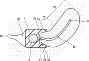
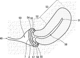
- FIG. 2 is a diagram showing an example of an ultrasonic imaging device inserted from the vaginal opening.
- the ultrasonic imaging device 1 is inserted from the vaginal opening 49 and placed in the vagina 50.
- the ultrasonic wave propagation portion 7 abuts on the uterine vaginal portion 56 and the vaginal fornix portion 55.
- the ultrasonic wave propagating portion 7 is pushed in the insertion direction together with the housing 2, so that the ultrasonic wave propagating portion 7 is in close contact with the uterine vaginal portion 56 and the vaginal fornix portion 55.
- the ultrasonic propagating portion 7 includes the vagina 50, the cervix 52, the uterine body 53, the uterine vaginal region 56, the vaginal fornix 55, the uterine ostium (external uterine ostium 57 and the internal uterine ostium 58), and the uterus. It contacts at least one contact point of 51.
- the ultrasonic wave transmitting unit 3 repeatedly transmits ultrasonic waves to the subject via the vibrator (or transducer) at regular time intervals.
- the ultrasonic wave transmitting unit 3 may be capable of transmitting ultrasonic waves in substantially all directions.
- the ultrasonic wave receiving unit 4 receives the reflected echo signal reflected from the subject via the vibrator.
- the ultrasonic wave receiving unit 4 may be capable of receiving ultrasonic waves in substantially all directions.
- the oscillator may function as at least one of the ultrasonic transmitting unit 3 and the ultrasonic receiving unit 4. That is, the ultrasonic transmitting unit 3 and the ultrasonic receiving unit 4 may be oscillators.
- the ultrasonic transmission unit 3 and the ultrasonic wave reception unit 4 are controlled by an ultrasonic transmission / reception control unit (not shown) included in the computer 11 and are controlled by a phase adjustment addition unit reception unit (not shown) included in the computer 11.
- the received reflected echo is phase-aligned and added.
- the housing 2 is formed by arranging a plurality of vibrators, and has a function of transmitting and receiving ultrasonic waves to a subject via the vibrators.
- the ultrasonic transmission unit 3 drives a vibrator to generate a wave transmission pulse for generating ultrasonic waves.
- the ultrasonic wave transmitting unit 3 has a function of setting the convergence point of the transmitted ultrasonic waves to a predetermined depth.
- the ultrasonic receiving unit 4 amplifies the reflected echo signal received by the vibrator with a predetermined gain to generate an RF signal (that is, a received signal).
- the phasing addition unit controls the phase of the RF signal amplified by the ultrasonic receiving unit 4, forms an ultrasonic beam for one or a plurality of convergence points, and outputs RF signal frame data (corresponding to RAW data). Generate.
- the ultrasonic information transmission unit 5 transmits the RF signal frame data generated by the phase adjustment addition unit as the ultrasonic information received by the ultrasonic reception unit 4.
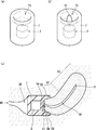
- FIG. 3 shows an example in which the housing 2 is a substantially cylindrical shape.
- FIG. 3A is an example of a perspective view of the ultrasonic wave propagating portion 7 having a recess.
- FIG. 3B is an example of a perspective view of the ultrasonic wave propagating portion 7 having a concave portion and a convex portion.
- FIG. 3C is a diagram showing an example of the ultrasonic imaging device 1 inserted from the vaginal opening 49.
- the housing 2 (or a part of the housing 2) is covered with the ultrasonic wave propagation portion 7.
- the ultrasonic wave propagation unit 7 is interposed between the living body and the housing 2 (or a part of the housing 2).
- the ultrasonic wave propagation section 7 includes a recess 71.
- the ultrasonic imaging device 1 is inserted from the vaginal opening 49 and placed in the vagina 50.
- the recess 71 abuts on the uterine vaginal portion 56 and the vaginal fornix portion 55.
- the concave portion 71 has a shape substantially opposed to the convex shape of the uterine vaginal portion 56 and the vaginal fornix portion 55.
- the recess 71 is brought into close contact with the uterine vaginal portion 56 and the vaginal fornix portion 55 by pushing the ultrasonic wave propagating portion 7 in the insertion direction.
- the ultrasonic propagation unit 7 is pushed in the insertion direction together with the housing 2, when the pressure exceeds a predetermined threshold value, the notification unit 10 notifies that the pressure exceeds the predetermined threshold value, which is safe and appropriate.
- the recess 71 can be brought into close contact with the uterine vaginal portion 56 and the vaginal fornix portion 55 by pressure.
- the ultrasonic wave propagation portion 7 includes a concave portion 71 and a convex portion 72.
- the ultrasonic imaging device 1 is inserted through the vaginal opening 49 and placed in the vagina 50.
- the recess 71 abuts on the uterine vaginal portion 56 and the vaginal fornix portion 55.
- the convex portion 72 abuts on the external uterine ostium 57.
- the concave portion 71 has a shape substantially opposed to the convex shape of the uterine vaginal portion 56 and the vaginal fornix portion 55.
- the convex portion 72 has a shape substantially opposed to the hole shape of the external uterine ostium 57.
- the concave portion 71 is in close contact with the uterine vaginal portion 56 and the vaginal fornix portion 55, and the convex portion 72 is in close contact with the external uterine ostium 57.
- the notification unit 10 notifies that the pressure exceeds a predetermined threshold, which is safe and appropriate. With pressure, the concave portion 71 can be brought into close contact with the uterine vaginal portion 56 and the vaginal fornix portion 55, and the convex portion 72 can be brought into close contact with the external uterine ostium 57.
- the ultrasonic propagating portion 7 includes the vagina 50, the cervix 52, the uterine body 53, the uterine vaginal region 56, the vaginal fornix 55, the uterine ostium (external uterine ostium 57 and the internal uterine ostium 58), and the uterus.
- the ultrasonic propagating portion 7 includes a shape that abuts at least one abutting portion of the uterine vaginal portion 56, the vaginal fornix portion 55, and the external uterine ostium 57 and substantially opposes the shape of the abutting portion.
- the ultrasonic wave propagation unit 7 can be brought into close contact with the contact point by including a shape substantially opposite to the shape of the contact point, and the ultrasonic wave can be generated between the living body as the subject and the ultrasonic image pickup device 1. Transmission and reception can be performed appropriately.
- FIG. 4 is a diagram showing an example of a piston type insertion portion 400.
- the insertion portion 400 includes a holding portion 40, a shaft portion 41, and a grip portion 46.
- the holding portion 40 is a tubular portion that is inserted from the vaginal opening 49 with the housing 2 stored inside and guides the housing 2 to a predetermined position.
- the insertion portion 400 has a detachable housing 2, and the housing 2 is inserted from the vaginal opening 49 in the insertion direction with the housing 2 (including the ultrasonic propagation portion 7) attached to the holding portion 40, and the shaft.
- the housing 2 is separated (or removed) at at least one predetermined position of the mouth 57 and the internal uterine ostium 58) and the uterus 51.
- the grip portion 46 is gripped, and the shaft portion 41 pushes the ultrasonic propagation portion 7 together with the housing 2 in the insertion direction, so that the ultrasonic propagation portion 7 has the vagina 50, the cervix 52, the uterine body 53, and the uterine vagina. It abuts or adheres to at least one contact point of the portion 56, the vaginal fornix 55, the uterine ostium (external cervix 57 and the internal uterine ostium 58), and the uterus 51.
- the insertion portion 400 can guide the housing 2 (which may include the ultrasonic wave propagation portion 7) to a predetermined position and appropriately indwell it.
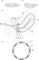
- FIG. 5 is a diagram showing an example of a substantially ring-shaped ultrasonic imaging device 1.
- the housing 2 has a substantially ring shape, and has a vaginal 50, a cervix 52, a uterine body 53, a uterine vaginal 56, a vaginal fornix 55, a uterine ostium (external uterine ostium 57 and an internal uterine ostium 58), and. It is attached to at least one of the uterus 51.
- the housing 2 has a substantially ring shape and is attached to the outer circumference 54 of the uterine vaginal portion 56. As a result, the housing 2 can be locked at a predetermined position.
- the substantially ring-shaped housing 2 has at least an elastic material and an elastic mechanism that can expand and contract in at least one direction in the circumferential direction and the radial direction of the substantially ring shape. Includes one.
- all or part of the housing 2 contains an elastic material (for example, an elastic body such as an elastomer), and all or part of the housing 2. May be stretchable.
- the substantially ring-shaped housing 2 may include a plurality of housings 21.
- the substantially ring-shaped housing 2 includes a telescopic mechanism 22 (for example, a spring, a piston, etc.) that connects a plurality of housings 21.
- the housing 21 includes an ultrasonic wave transmitting unit 3, an ultrasonic wave receiving unit 4, and an ultrasonic wave information transmitting unit 5, similarly to the housing 2.
- the expansion / contraction mechanism 22 may be an expansion / contraction material (for example, an elastic body such as an elastomer).
- the elastic material or the elastic mechanism is urged to contract in at least one direction in the circumferential direction and the radial direction, so that a force acts on the inner side in the radial direction to act on the uterine vagina. It is attached to the outer circumference 54 of 56. As a result, the housing 2 can be locked at a predetermined position.
- the housing 2 By urging the elastic material or the elastic mechanism so as to extend in at least one direction in the circumferential direction and the radial direction, a force acts on the outer side in the radial direction, and the vagina 50, the cervix 52, the uterine body 53, and the vagina It may be attached to at least one of the fornix 55, the uterine ostium (external uterine ostium 57 and the internal uterine ostium 58), and the uterus 51. As a result, the housing 2 can be locked at a predetermined position.
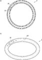
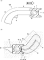
- FIG. 6 is a diagram showing a modified example of the substantially ring-shaped housing 2.
- FIG. 6A is a cross-sectional view of a modified example of the substantially ring-shaped housing 2.
- FIG. 6B is a perspective view of a modified example of the substantially ring-shaped housing 2.
- the substantially ring-shaped housing 2 includes an oscillator 20 that can move in the circumferential direction in a substantially ring-shaped internal space 221.
- the oscillator 20 functions as at least one of the ultrasonic transmitting unit 3 and the ultrasonic receiving unit 4.
- at least one of the ultrasonic transmitting unit 3 and the ultrasonic receiving unit 4 is movable in the circumferential direction of a substantially ring shape.
- the oscillator 20 By making the oscillator 20 movable in the circumferential direction in the internal space 221, the oscillator 20 can be moved to a position where the image pickup target is imaged. Further, since the vibrator 20 can be made smaller than the case where the vibrators are provided in all the circumferential directions of the substantially ring-shaped housing 2, the heat generated by the vibrators can be reduced.
- FIG. 7 is a diagram showing that the substantially ring-shaped housing 2 (or a part of the housing 2) is covered with the ultrasonic wave propagation portion 7.
- the ultrasonic wave propagation unit 7 expands by absorbing or filling at least one of a liquid and a gel, and intervenes between the living body and the housing 2 (or a part of the housing 2).
- the ultrasonic propagating portion 7 expands by absorbing body fluid and presses the subject, so that the vagina, cervix, uterine body, uterine vagina, vaginal fornix, etc.
- the housing 2 can be locked at the cervix and at least one predetermined position of the uterus.
- FIG. 8 is a diagram showing that the substantially ring-shaped housing 2 (or a part of the housing 2) is covered with the balloon-shaped ultrasonic wave propagating portion 7.
- the balloon-shaped ultrasonic wave propagating portion 7 expands by filling the balloon with at least one of a liquid and a gel, and intervenes between the living body and the housing 2 (or a part of the housing 2).
- the injection unit (syringe) 44 injects at least one of the liquid and gel into the ultrasonic wave propagation unit 7 through the tube 45, and fills the balloon with at least one of the liquid and gel from the injection port 25.
- the inlet 25 may include a check valve structure to prevent backflow of liquid or gel in the balloon.
- the balloon-shaped ultrasonic propagating portion 7 expands by filling at least one of a liquid and a gel to press the subject, whereby the vagina 50, the cervix 52, the uterine body 53, the vaginal fornix 55,
- the housing 2 can be locked at at least one predetermined position of the uterine ostium (external uterine ostium 57 and internal uterine ostium 58) and the uterus 51.
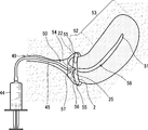
- FIG. 9 is a diagram showing an example of an insertion portion for inserting the substantially ring-shaped housing 2 into the vagina.
- the insertion portion 30 includes a shaft portion 31, a grip portion 32, and a mounting portion 36. Further, the insertion portion 30 includes a guide portion 35 that guides the substantially ring-shaped housing 2 to a predetermined position. At the position guided by the guide portion 35, the shaft portion 31 pushes the housing 2 in the insertion direction, so that the housing 2 (which may include the ultrasonic propagating portion 7) becomes the vagina 50, the cervix 52, and the uterine body.
- the insertion portion 30 includes a separation portion (slider 33 and slide groove 34).
- the slider 33 and the slide groove 34 have the same function as the slide switch, and the housing 2 can be separated by sliding the slider 33 along the slide groove 34 in the insertion direction or in the direction opposite to the insertion direction. ..
- the ultrasonic information receiving unit 8, the pressure information receiving unit 9, and the notification unit 10 shown in FIG. 1 may be provided in the insertion unit 30.
- the notification unit 10 notifies that the pressure exceeds a predetermined threshold value when the pressure exceeds a predetermined threshold value.
- the housing 2 can be pushed into a predetermined position with a safe and appropriate pressure.
- the ultrasonic information receiving unit 8 receives ultrasonic information from the ultrasonic information transmitting unit 5 by wire or wirelessly with the insertion unit 30 attached to the housing 2.
- the housing 2 can be placed at a predetermined position while checking the ultrasonic image on a monitor or the like based on the ultrasonic information received by the ultrasonic information receiving unit 8.
- the ultrasonic information receiving unit 8 is provided in at least one of the guide unit 35 and the mounting unit 36.
- the insertion portion 30 can guide the housing 2 (which may include the ultrasonic wave propagation portion 7) to a predetermined position and appropriately indwell it.
- FIG. 9B are perspective views showing an example of the guide portion 35 and the mounting portion 36.
- a convex guide portion 35-1 and a mounting portion 36 are provided.
- the guide portion 35 (convex guide portion 35-1) and the mounting portion 36 are moved in the opposite directions of the insertion direction and the insertion direction. It is relatively mobile.
- a substantially ring-shaped housing 2 is mounted on the mounting base 39 of the mounting portion 36.
- the housing 2 is inserted from the vaginal opening 49 in the insertion direction with the mounting portion 36 wearing the housing 2 (which may include the ultrasonic propagation portion 7), and the shaft portion 31 is the housing 2 (ultrasonic propagation portion 7).
- the slider 33 By pushing in the insertion direction and sliding the slider 33, at at least one predetermined position of the vagina, cervix, uterine body, uterine vagina, vaginal fornix, uterine ostium, and uterus.
- the housing 2 is separated (or removed).
- the housing 2 when the convex guide portion 35-1 is inserted into the external uterine ostium 57 and the shaft portion 31 is pushed in the insertion direction, the housing 2 is located near the outer circumference 54 of the uterine vaginal portion 56. There is. In this way, the guide portion 35 guides the substantially ring-shaped housing 2 to at least one predetermined position of the vagina, the cervix, the uterine body, the uterine vagina, the vaginal fornix, and the uterine ostium.
- a concave guide portion 35-2 and a mounting portion 36 are provided.
- the guide portion 35 (concave guide portion 35-2) and the mounting portion 36 are relatively movable in the insertion direction and in the opposite directions of the insertion direction.
- the housing 2 is located near the outer circumference 54 of the uterine vaginal portion 56.
- the guide portion 35 guides the substantially ring-shaped housing 2 to at least one predetermined position of the vagina, the cervix, the uterine body, the uterine vagina, the vaginal fornix, and the uterine ostium.
- a convex guide portion 35-1, a concave guide portion 35-2, and a mounting portion 36 are provided.
- the guide portion 35 (convex guide portion 35-1 and concave guide portion 35-2) and the mounting portion 36 are relatively movable in the insertion direction and in the opposite directions of the insertion direction.
- the guide portion 35 is the vaginal 50, the cervix 52, the uterine body 53, the uterine vaginal 56, the vaginal fornix 55, the uterine ostium (external uterine ostium 57 and the internal uterine ostium 58), and the uterus 51. It comprises at least one of a protrusion and a recess to abut or insert into at least one.
- the guide portion 35 is at least one predetermined of the vagina 50, the cervix 52, the uterine body 53, the uterine vaginal region 56, the vaginal fornix 55, the uterine ostium (external uterine ostium 57 and the internal uterine ostium 58), and the uterus 51.
- the housing 2 is guided to the position of.
- at least one of the convex portion and the concave portion is a vagina 50, a cervix 52, a uterine body 53, a uterine vagina 56, a vaginal fornix 55, a uterine ostium (external uterine ostium 57 and an internal uterine ostium 58).
- magnetism may be applied to the side surface 35-3 of the guide portion 35 (convex guide portion 35-1 or concave guide portion 35-2), and the mounting force of the housing 2 may be increased by the magnetic force.
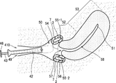
- FIG. 10 is a diagram showing an example of a substantially capsule type ultrasonic image pickup apparatus 1 and an injection type insertion portion 410.
- the insertion portion 410 includes a holding portion 42, a shaft portion 43, and a grip portion 46.
- the holding portion 42 is a tubular portion that is inserted from the vaginal opening 49 with the housing 2 stored inside and guides the housing 2 to a predetermined position.
- the insertion portion 410 has a substantially capsule-shaped housing 2 that can be attached and detached, and the holding portion 42 is attached to the housing 2 (which may include the ultrasonic propagation portion 7) and is housing from the vaginal opening 49 in the insertion direction. 2 is inserted, and the shaft portion 43 pushes the housing 2 (which may include the ultrasonic propagation portion 7) in the insertion direction, while the vagina 50, the cervix 52, the uterine body 53, the uterine vagina 56, and the vaginal fornix.
- the housing 2 is separated (or removed) at at least one predetermined position of the portion 55, the uterine ostium (external uterine ostium 57 and the internal uterine ostium 58), and the uterus 51.
- the shaft portion 43 pushes the housing 2 inside the holding portion (cylindrical portion) 41 in the insertion direction, the housing 2 is pushed out from the tubular portion, and the housing 2 is separated at a predetermined position.
- the insertion portion 410 guides the housing 2 (which may include the ultrasonic wave propagation portion 7) to a predetermined position and allows the housing 2 to be appropriately placed.
- two substantially capsule-shaped housings 2 are placed at the respective positions of the anterior vaginal fornix 55-1 and the posterior vaginal fornix 55-2.
- the plurality of housings 2 include the vagina 50, the cervix 52, the uterine body 53, the uterine vaginal region 56, the vaginal fornix 55, the uterine ostium (external uterine ostium 57 and the internal uterine ostium 58), and the uterus.
- Each may be placed in at least one predetermined position of 51.
- the grip portion 46 is gripped, and the shaft portion 43 pushes the ultrasonic propagation portion 7 together with the housing 2 in the insertion direction, so that the ultrasonic propagation portion 7 has the vagina 50, the cervix 52, the uterine body 53, and the uterine vagina. It abuts or adheres to at least one contact point of the portion 56, the vaginal fornix 55, the uterine ostium (external cervix 57 and the internal uterine ostium 58), and the uterus 51.
- FIG. 11 is a diagram showing an example of a substantially cannonball type (or umbrella type) ultrasonic image pickup device 1 and a gun type insertion portion 420.
- the insertion portion 420 includes a shaft portion 31, a grip portion 32, and a mounting portion 26.
- the mounting portion 26 has a attachment / detachment mechanism such as a latch.
- the insertion portion 420 includes a separation portion (trigger 75). By pulling the trigger 75, the attachment / detachment mechanism such as the latch is released, and the housing 2 can be separated.
- the insertion portion 420 has a detachable housing 2, and the housing 2 is inserted from the vaginal opening 49 in the insertion direction with the housing 2 (including the ultrasonic propagation portion 7) attached to the mounting portion 26, and the shaft
- the housing 2 is separated (or removed) at at least one predetermined position of the mouth 57 and the internal uterine ostium 58) and the uterus 51.
- the grip portion 32 is gripped and the shaft portion 31 pushes the housing 2 in the insertion direction, so that the housing 2 and the ultrasonic propagating portion 7 are combined with the vagina 50 and the cervix 52.
- the ultrasonic information receiving unit 8, the pressure information receiving unit 9, and the notification unit 10 shown in FIG. 1 may be provided in the insertion unit 420.
- the notification unit 10 notifies that the pressure exceeds a predetermined threshold value when the pressure exceeds a predetermined threshold value.
- the housing 2 can be pushed into a predetermined position with a safe and appropriate pressure.
- the ultrasonic information receiving unit 8 receives the ultrasonic information from the ultrasonic information transmitting unit 5 by wire or wirelessly with the insertion unit 420 attached to the housing 2.
- the housing 2 can be placed at a predetermined position while checking the ultrasonic image on a monitor or the like based on the ultrasonic information received by the ultrasonic information receiving unit 8.
- the ultrasonic information receiving unit 8 is provided in the mounting unit 26.
- the insertion portion 420 can guide the housing 2 (which may include the ultrasonic wave propagation portion 7) to a predetermined position and appropriately indwell it.
- FIG. 12 is a diagram showing an example of an ultrasonic imaging device that holds a state in which the housing 2 (which may include the ultrasonic wave propagating portion 7) is inserted at a predetermined position by sandwiching the housing 2 from inside and outside the body. is there.
- the sandwiching portion 80 includes a curved portion extending from the housing 2 side and having a substantially curved shape.
- the curved portion of the holding portion 80 expands and contracts due to elastic force, and when the curved portion expands in the direction in which the radius of curvature of the curved portion becomes longer, a force acts to contract in the direction in which the radius of curvature of the curved portion becomes shorter.
- the curved portion of the sandwiching portion 80 has a function of a spring.
- the sandwiching portion 80 of the ultrasonic imaging device 1 extends from the housing side and is sandwiched from inside and outside the body with the housing 2 inserted from the vaginal opening, so that the housing 2 is inserted at a predetermined position. To hold.
- the ultrasonic imaging device 1 has an ultrasonic transmitting unit 3, an ultrasonic receiving unit 4, and an ultrasonic information transmitting unit 5 on the side opposite to the housing 2 side of the sandwiching unit 80.
- An operation unit 81 for driving at least one is provided. For example, by turning the button of the operation unit 81 ON / OFF, at least one of the ultrasonic wave transmission unit 3, the ultrasonic wave reception unit 4, and the ultrasonic wave information transmission unit 5 can be driven or stopped. it can.
- the substantially spherical housing 2 is inserted from the vaginal opening 49.
- the housing 2 may have at least one shape of a substantially ring shape, a substantially sphere, a substantially ellipsoid, a substantially cannonball type, a substantially umbrella type, a substantially capsule type, and a substantially rotating body.
- a part of the housing 2 and the holding portion 80 on the housing side is inserted into the vaginal opening 49, and a part of the holding portion 80 on the side opposite to the housing side is ashamed from the vaginal opening 49. Extend to the hill side. Further, with the housing 2 inserted from the vaginal opening 49, the curved portion of the holding portion 80 expands in the direction in which the radius of curvature of the curved portion becomes longer, and attempts to contract in the direction in which the radius of curvature of the curved portion becomes shorter. The power to do works. By this action, the holding portion 80 holds the state in which the housing 2 is inserted at a predetermined position by holding the housing 2 from inside and outside the body while the housing 2 is inserted from the vaginal opening 49.
- FIG. 13 is a diagram showing an example of an ultrasonic information receiving unit that receives ultrasonic information from the ultrasonic information transmitting unit 5.
- the ultrasonic information receiving unit 60 has a substantially cannonball-shaped housing 2 that can be attached and detached, and when the housing 2 is attached, ultrasonic information is ultrasonically transmitted by wire or wirelessly. Received from the information transmission unit 5.
- the ultrasonic information received by the ultrasonic information receiving unit 60 is input to the computer 500 via the cable 62 and the connection terminal 61.
- the computer 500 generates an ultrasonic image (two-dimensional tomographic image or three-dimensional image) of the subject based on the input ultrasonic information and displays it on a display unit (not shown).
- the computer 500 may be a tablet terminal, a mobile terminal, or a smartphone.
- the computer 500 constructs a two-dimensional image (two-dimensional tomographic image) from the luminance information which is the image information based on the luminance value of the RF signal frame data generated by the phase adjustment addition unit. Further, the computer 500 inputs the RF signal frame data output from the phase adjustment addition unit, performs signal processing such as gain correction, log compression, detection, contour enhancement, and filter processing, and performs two-dimensional image (two-dimensional). Compose a tomographic image).
- the computer 500 is three-dimensional based on a storage unit (not shown) that stores the configured two-dimensional tomographic image in association with the acquisition position (acquisition coordinates) and the acquisition position of the two-dimensional image (two-dimensional tomographic image).
- a volume data generation unit (not shown) that performs coordinate conversion and interpolation processing to generate volume data, and volume rendering using opacity based on the volume data generated by the volume data generation unit are performed to create a three-dimensional image.
- the movement information of the 3D image information about movement, rotation, enlargement, reduction, etc.
- section position information section coordinate information
- the section coordinate calculation unit (not shown) that calculates the section position (section coordinates) for the movement of the section (including the three orthogonal sections) corresponding to the movement of the three-dimensional image, and the section calculated by the section coordinate calculation unit. Based on the position information (section coordinate information), data is extracted from the storage unit to generate an orthogonal three-section image of the section image (two-dimensional tomographic image) according to the movement of the three-dimensional image (three-dimensional elastic image). At least one cross section is selected from the cross section image component (not shown) and the orthogonal three cross section image (two-dimensional tomographic image), and the selected cross section (selected cross section) is compared with the three-dimensional image (three-dimensional elastic image).
- a three-dimensional image composed of a selected cross-section image generation unit (not shown) and a volume rendering unit that generate a selected cross-section image (two-dimensional tomographic image) according to the movement (movement, rotation, enlargement, reduction, etc.) of (Three-dimensional elastic image) and a display unit (not shown) for displaying the selected cross-sectional image generated by the selected cross-sectional image generation unit are provided.
- the ultrasonic information receiving unit 63 has a substantially ring-shaped housing 2 that can be attached and detached, and when the housing 2 is attached, ultrasonic information is ultrasonically transmitted by wire or wirelessly. Received from the information transmission unit 5. The ultrasonic information received by the ultrasonic information receiving unit 63 is input to the computer 500 via the cable 62 and the connection terminal 61.
- the ultrasonic information receiving unit 64 has a substantially spherical housing 2 that can be attached and detached, and when the housing 2 is attached, ultrasonic information is ultrasonically transmitted by wire or wirelessly. Received from the information transmission unit 5. The ultrasonic information received by the ultrasonic information receiving unit 64 is input to the computer 500 via the cable 62 and the connection terminal 61.
- the housing 2 in FIG. 13 may include a battery that supplies electric power to the ultrasonic transmitting unit 3 and the ultrasonic receiving unit 4. Further, the ultrasonic information receiving units 60, 63, 64 have a detachable housing 2, and when the housing 2 is attached, a power supply unit (not shown) that supplies power to the battery by wire or wirelessly. May be provided.
- the ultrasonic information receiving units 60, 63, 64 include a fitting portion 65 for fitting the housing 2.
- the power supply portion may supply electric power to the battery by wire or wirelessly.
- ultrasonic information can be transmitted and received by wire or wirelessly, and power can be supplied to the battery by wire or wirelessly.
- the housing 2 may include a power supply unit, generate power by at least one of thermoelectric power generation, vibration power generation, and electromagnetic wave power generation, and supply power to the battery. As a result, the housing 2 can generate electricity, and an image can be taken for a long time in the indwelling state.
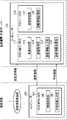
- FIG. 14 is a diagram showing an example of an ultrasonic imaging system that displays diagnostic information on the subject side (patient side).
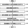
- FIG. 15 is a flow chart showing an example of the operation of the ultrasonic imaging system that displays diagnostic information on the subject side (patient side).
- the ultrasonic imaging system includes an ultrasonic imaging device 1, a computer 100 installed on the subject side (patient side), and a computer 110 installed on a medical institution (or an external server). And.
- the computers 100 and 110 may be tablet terminals, mobile terminals, or smartphones.
- the computer 100 includes an arithmetic unit (CPU, MPU, or GPU) 101.
- the arithmetic unit 101 includes an information acquisition unit 102 and a reservation information input unit 103.
- the computer 110 includes an arithmetic unit (CPU, MPU, or GPU) 111 and a storage unit (memory or HDD) 112.
- the arithmetic unit 111 includes an image generation unit 113, an image acquisition unit 114, a diagnostic information input unit 115, and a diagnostic information transmission unit 116.
- the storage unit 112 includes an image storage unit 117 and a diagnostic information storage unit 118.
- the ultrasonic image pickup device 1 transmits ultrasonic information to the computer 110.
- the image generation unit 113 generates an ultrasonic image from the ultrasonic information in the same manner as the computer 500 (step S10).
- the image storage unit 117 stores the ultrasonic image (step S11).
- the image acquisition unit 114 acquires an ultrasonic image from the image storage unit 117 (step S12).
- the diagnostic information input unit 115 inputs diagnostic information based on the ultrasonic image acquired by the image acquisition unit 114 (step S13), and stores the diagnostic information in the diagnostic information storage unit 118.
- Diagnosis information includes diagnosis date and time, subject attribute information, medical images (ultrasound images, CT images, MR images, etc.), examination attribute information (examination items, etc.), examination results, findings by medical staff, prescription drugs, etc. It includes at least one of input history, inputter attribute information, consultation schedule, and appointment status.
- the consultation schedule includes information indicating that it is necessary to revisit within a predetermined period, test attribute information for revisit, and the like.
- the reservation status includes at least one of free information and calendar information indicating the date and time when reservation is possible.
- the diagnostic information transmission unit 116 acquires the diagnostic information and transmits the diagnostic information to the information acquisition unit 102 on the subject side (patient side) (step S14).
- the information acquisition unit 102 acquires the diagnostic information from the diagnostic information transmission unit 116, and displays the diagnostic information on the display unit (not shown) of the computer 100.
- the reservation information input unit 103 inputs the reservation information of the medical institution based on the reservation status displayed on the display unit (step S15).
- the entered reservation information is transmitted to the computer 110 in association with the diagnostic information, and is stored in the diagnostic information storage unit 118.
- Reservation information includes reservation date and time, reservation change, reservation cancellation, input history, and the like.
- the housing 2 of the ultrasonic imaging device 1 is placed in the body, and the subject can acquire an ultrasonic image and diagnostic information without going to a medical institution. It is possible to reduce the time and financial burden on the person. Further, since the ultrasonic image can be acquired while the housing 2 of the ultrasonic imaging device 1 is indwelled in the body, the ultrasonic imaging device 1 is inserted from the vaginal opening every time the ultrasonic image is acquired. It is not necessary to take it out or take it out, and the mental burden on the subject can be reduced. In addition, if it is necessary to return to the clinic, the appointment information of the medical institution can be easily entered.
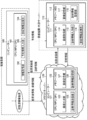
- FIG. 16 is a diagram showing an example of an ultrasonic imaging system using a cloud.
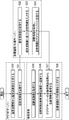
- FIG. 17 is a flow chart showing an example of the operation of the ultrasonic imaging system using the cloud.
- the ultrasonic imaging system includes an ultrasonic imaging device 1, a computer 100 installed on the subject side (patient side), and a computer 110 installed on a medical institution (or an external server). And a cloud server 120.
- the computers 100 and 110 may be tablet terminals, mobile terminals, or smartphones.
- the computer 100 includes an arithmetic unit (CPU, MPU, or GPU) 101.
- the arithmetic unit 101 includes an information acquisition unit 102, a reservation information input unit 103, and a request information transmission unit 104.
- the computer 110 includes an arithmetic unit (CPU, MPU, or GPU) 111 and a storage unit (memory or HDD) 112.
- the arithmetic unit 111 includes an image acquisition unit 114, a diagnostic information input unit 115, and a diagnostic information transmission unit 116.
- the storage unit 112 includes an image storage unit 117 and a diagnostic information storage unit 118.
- the cloud server 120 includes an arithmetic unit (CPU, MPU, or GPU) 121 and a storage unit (memory or HDD) 122.
- the arithmetic unit 121 includes an image generation unit 123 and a diagnostic information transmission unit 126.
- the storage unit 122 includes an image storage unit 127 and a diagnostic information storage unit 128.
- the ultrasonic imaging device 1 transmits ultrasonic information to the cloud server 120.
- the image generation unit 123 generates an ultrasonic image from the ultrasonic information in the same manner as the computer 500 (step S20).
- the image storage unit 127 stores an ultrasonic image (step S21).
- the image acquisition unit 114 acquires an ultrasonic image from the image storage unit 127 (step S22).
- the diagnostic information input unit 115 inputs diagnostic information based on the ultrasonic image acquired by the image acquisition unit 114 (step S23), and stores the diagnostic information in the diagnostic information storage unit 118.
- the diagnostic information transmission unit 116 acquires the diagnostic information and transmits the diagnostic information to the cloud server 120 (step S24).
- the diagnostic information transmitted to the cloud server 120 is stored in the diagnostic information storage unit 128.
- the information acquisition unit 102 acquires an ultrasonic image from the image storage unit 127 (step S25).
- the information acquisition unit 102 causes the ultrasonic image to be displayed on the display unit (not shown) of the computer 100.
- the request information transmitting unit 104 inputs the request information for requesting the diagnostic information and transmits it to the diagnostic information transmitting unit 126 (step S26).
- the diagnostic information transmission unit 126 acquires diagnostic information in response to the request information, and transmits the diagnostic information to the information acquisition unit 102 on the subject side (patient side).
- the information acquisition unit 102 acquires diagnostic information from the diagnostic information transmission unit 126 of the cloud server 120 (step S27).
- the reservation information input unit 103 inputs the reservation information of the medical institution based on the reservation status displayed on the display unit (step S28).
- the entered reservation information is transmitted to the computer 110 in association with the diagnostic information, and is stored in the diagnostic information storage unit 118.
- a plurality of medical institutions can be connected to the cloud server 120, and the above-mentioned ultrasonic imaging system can be provided to each medical institution. And the convenience of the subject is enhanced.
- the objects to be imaged in the ultrasonic image in the ultrasonic imaging apparatus and the ultrasonic imaging system of the present embodiment are mainly the uterus, the ovary, the foetation, and the fetal appendages (placenta, amniotic fluid, etc.), but the peripheral organs thereof.
- the peripheral organs may be abdominal organs such as the bladder, kidneys, intestinal tract, and rectum.
- the shaft portions 41 and 43 manually push the housing 2 by gripping the grip portion 46, but the shaft portion 41 is automatically controlled by the machine. , 43 may push the housing 2. Further, the shaft portions 41 and 43 may push the housing 2 stepwise by mechanical control.
- the ultrasonic imaging apparatus 1 transmits ultrasonic information to the computer 110 or the cloud server 120, but transmits the ultrasonic information to the computer 110 via the computer 100 on the subject side or another computer. Alternatively, it may be transmitted to the cloud server 120.
- the other computer may be a tablet terminal, a mobile terminal, or a smartphone.
- the request information transmitting unit 104 inputs the request information for requesting the diagnostic information and transmits it to the diagnostic information transmitting unit 126 of the cloud server 120. It may be transmitted to the diagnostic information transmission unit 116 of the computer 110 on the medical institution side.
- the reservation information input unit 103 inputs the reservation information of the medical institution to the computer 110 on the medical institution side, but reserves the medical institution to the cloud server 120. You may enter the information.
- the entered reservation information may be transmitted to the cloud server 120 in association with the diagnostic information and stored in the diagnostic information storage unit 128.
- the computer 110 on the medical institution side may acquire the reservation information from the cloud server 120 and store it in the diagnostic information storage unit 118.
- the computer 100 on the subject side may generate an ultrasonic image from the ultrasonic information in the same manner as the computer 500.
- the computer 100 on the subject side capable of communicating with the ultrasonic imaging device 1 including the housing 2, and the computer 100 on the subject side is inserted from the vaginal opening of the subject and is inserted into the vagina and cervix.
- the uterine body, the cervix, the vaginal fornix, the uterine ostium, and the housing 2 inserted in at least one predetermined position of the uterus, with the housing 2 inserted in the predetermined position and reflected from the object.
- An image generation unit (not shown) that generates an ultrasonic image based on ultrasonic information may be provided.
- the ultrasonic information is input to the computer 100 from the ultrasonic information transmission unit 5 of the housing 2 via wired communication or wireless communication.
- the image generation unit (not shown) generates an ultrasonic image (two-dimensional tomographic image or three-dimensional image) of the subject based on the input ultrasonic information and displays it on the display unit (not shown). ..
- the computer 100 may be a tablet terminal, a mobile terminal, or a smartphone. As a result, the subject side (patient side) can directly see the ultrasonic image (two-dimensional tomographic image or three-dimensional image) generated based on the ultrasonic information received from the housing 2.
- the computer 100 on the subject side may receive a switching signal from the outside and can switch between generation and non-generation of the ultrasonic image based on the switching signal.
- the ultrasonic information transmitting unit 5 that transmits ultrasonic information to the computer 100 on the subject side (patient side) receives the switching signal from the outside, and transmits and does not transmit the ultrasonic information based on the switching signal. It may be switchable.
- the image generation unit (not shown) of the computer 100 on the subject side is used when the area of the brightness of a predetermined reference value exceeds the threshold value in the two-dimensional tomographic image of the ultrasonic image.
- a notification may be transmitted to notify that the area area has exceeded a predetermined threshold value by sound, light, vibration, or the like.
- the computer 100 on the subject side includes an ultrasonic information receiving unit 8, a pressure information receiving unit 9, and a notification unit 10, and can be wired or wirelessly connected to the computer 11 and signals. You may send and receive.
- the ultrasonic information receiving unit 8 receives ultrasonic information from the ultrasonic information transmitting unit 5.
- the image generation unit (not shown) of the computer 100 on the subject side (patient side) generates an ultrasonic image based on the ultrasonic information received by the ultrasonic information receiving unit 8, and the notification unit 10 super
- the region area of the brightness of the predetermined reference value exceeds the threshold value
- the fact that the region area exceeds the predetermined threshold value is notified by sound, light, vibration, or the like.
- the housing 2 can be inserted or placed at an appropriate position by notifying when the area of the brightness of the predetermined reference value exceeds the threshold value. For example, by setting the brightness below a predetermined reference value, it is possible to identify the region of the follicle in which the brightness value appears small in the two-dimensional tomographic image, and it is appropriate to obtain a two-dimensional tomographic image including the follicle by notification.
- the housing 2 can be inserted or indwelled at the position.
- the ultrasonic imaging device and the ultrasonic imaging system since the housing of the ultrasonic imaging device is placed in the body, the time and financial burden and the mental burden on the subject can be reduced. It is useful as an imaging device and an ultrasonic imaging system.
Landscapes
- Life Sciences & Earth Sciences (AREA)
- Health & Medical Sciences (AREA)
- Biomedical Technology (AREA)
- Biophysics (AREA)
- Nuclear Medicine, Radiotherapy & Molecular Imaging (AREA)
- Pathology (AREA)
- Radiology & Medical Imaging (AREA)
- Engineering & Computer Science (AREA)
- Physics & Mathematics (AREA)
- Heart & Thoracic Surgery (AREA)
- Medical Informatics (AREA)
- Molecular Biology (AREA)
- Surgery (AREA)
- Animal Behavior & Ethology (AREA)
- General Health & Medical Sciences (AREA)
- Public Health (AREA)
- Veterinary Medicine (AREA)
- Ultra Sonic Daignosis Equipment (AREA)
- Surgical Instruments (AREA)
Priority Applications (1)
| Application Number | Priority Date | Filing Date | Title |
|---|---|---|---|
| JP2021537646A JPWO2021024709A1 (enExample) | 2019-08-02 | 2020-07-13 |
Applications Claiming Priority (2)
| Application Number | Priority Date | Filing Date | Title |
|---|---|---|---|
| JP2019143319 | 2019-08-02 | ||
| JP2019-143319 | 2019-08-02 |
Publications (1)
| Publication Number | Publication Date |
|---|---|
| WO2021024709A1 true WO2021024709A1 (ja) | 2021-02-11 |
Family
ID=74504025
Family Applications (1)
| Application Number | Title | Priority Date | Filing Date |
|---|---|---|---|
| PCT/JP2020/027296 Ceased WO2021024709A1 (ja) | 2019-08-02 | 2020-07-13 | 超音波撮像システム及び超音波撮像装置 |
Country Status (2)
| Country | Link |
|---|---|
| JP (1) | JPWO2021024709A1 (enExample) |
| WO (1) | WO2021024709A1 (enExample) |
Citations (5)
| Publication number | Priority date | Publication date | Assignee | Title |
|---|---|---|---|---|
| JPH01107745A (ja) * | 1987-10-20 | 1989-04-25 | Yokogawa Medical Syst Ltd | 胎児監視装置 |
| JPH0819542A (ja) * | 1994-07-04 | 1996-01-23 | Ichiro Kitagawa | 産婦人科経ちつ超音波診断装置のプローベのための 先端に水袋を備えたゴムカバー |
| JP2003180694A (ja) * | 2001-12-07 | 2003-07-02 | Ge Medical Systems Global Technology Co Llc | 超音波探触子 |
| JP2006141809A (ja) * | 2004-11-22 | 2006-06-08 | Olympus Corp | 超音波診断医用カプセル及び超音波診断医用カプセル装置 |
| JP2014073271A (ja) * | 2012-10-04 | 2014-04-24 | Toshiba Corp | 超音波医療装置及び超音波画像診断装置 |
-
2020
- 2020-07-13 JP JP2021537646A patent/JPWO2021024709A1/ja active Pending
- 2020-07-13 WO PCT/JP2020/027296 patent/WO2021024709A1/ja not_active Ceased
Patent Citations (5)
| Publication number | Priority date | Publication date | Assignee | Title |
|---|---|---|---|---|
| JPH01107745A (ja) * | 1987-10-20 | 1989-04-25 | Yokogawa Medical Syst Ltd | 胎児監視装置 |
| JPH0819542A (ja) * | 1994-07-04 | 1996-01-23 | Ichiro Kitagawa | 産婦人科経ちつ超音波診断装置のプローベのための 先端に水袋を備えたゴムカバー |
| JP2003180694A (ja) * | 2001-12-07 | 2003-07-02 | Ge Medical Systems Global Technology Co Llc | 超音波探触子 |
| JP2006141809A (ja) * | 2004-11-22 | 2006-06-08 | Olympus Corp | 超音波診断医用カプセル及び超音波診断医用カプセル装置 |
| JP2014073271A (ja) * | 2012-10-04 | 2014-04-24 | Toshiba Corp | 超音波医療装置及び超音波画像診断装置 |
Also Published As
| Publication number | Publication date |
|---|---|
| JPWO2021024709A1 (enExample) | 2021-02-11 |
Similar Documents
| Publication | Publication Date | Title |
|---|---|---|
| EP2977012B1 (en) | Ultrasound imaging apparatus and controlling method thereof | |
| CA2693730A1 (en) | Wired or wireless remotely controlled ultrasonic transducer and imaging apparatus | |
| KR102697909B1 (ko) | 초음파 장치 및 그 제어방법 | |
| CN106175826A (zh) | 超声图像显示设备和显示超声图像的方法 | |
| KR20170047873A (ko) | 초음파 영상 장치 및 그 제어 방법 | |
| US10702243B2 (en) | Ultrasound diagnosis apparatus, wearable device, method of controlling ultrasound diagnosis apparatus, method of controlling wearable device, and recording medium having methods recorded thereon | |
| EP3195807B1 (en) | Ultrasonic imaging apparatus | |
| KR20120090470A (ko) | 모바일 단말기를 이용한 휴대용 초음파 진단장치 | |
| KR102333542B1 (ko) | 초음파 프로브 및 그 제어 방법 | |
| KR20160050395A (ko) | 의료 영상 표시 방법 및 장치 | |
| EP2901938B1 (en) | Ultrasonic probe and ultrasonic diagnostic apparatus including the same | |
| KR102840187B1 (ko) | 초음파 영상 장치 및 그 제어 방법 | |
| US20230309963A1 (en) | Ultrasonic system for point of care and related methods | |
| WO2021024709A1 (ja) | 超音波撮像システム及び超音波撮像装置 | |
| KR102381763B1 (ko) | 웨어러블 초음파 진단장치 | |
| US20160066887A1 (en) | Image indicator provision in ultrasound system | |
| KR102351127B1 (ko) | 초음파 진단 방법 및 초음파 진단 장치 | |
| EP3031398A1 (en) | Ultrasound diagnostic apparatus and control method for the same | |
| KR20080045480A (ko) | 휴대용 초음파 장치 | |
| US20250325250A1 (en) | Ultrasound imaging apparatus for providing body marker and control method thereof | |
| EP3861936B1 (en) | Ultrasound diagnostic apparatus and method of processing ultrasound image | |
| KR20180100925A (ko) | 초음파 진단 장치 및 그 제어방법 | |
| Salles et al. | Hydrocele of the canal of Nuck | |
| Takacs et al. | Compact anatomically guided ultrasound for casualty care |
Legal Events
| Date | Code | Title | Description |
|---|---|---|---|
| 121 | Ep: the epo has been informed by wipo that ep was designated in this application |
Ref document number: 20850397 Country of ref document: EP Kind code of ref document: A1 |
|
| ENP | Entry into the national phase |
Ref document number: 2021537646 Country of ref document: JP Kind code of ref document: A |
|
| NENP | Non-entry into the national phase |
Ref country code: DE |
|
| 122 | Ep: pct application non-entry in european phase |
Ref document number: 20850397 Country of ref document: EP Kind code of ref document: A1 |