WO2021024690A1 - マイクロホン - Google Patents
マイクロホン Download PDFInfo
- Publication number
- WO2021024690A1 WO2021024690A1 PCT/JP2020/026845 JP2020026845W WO2021024690A1 WO 2021024690 A1 WO2021024690 A1 WO 2021024690A1 JP 2020026845 W JP2020026845 W JP 2020026845W WO 2021024690 A1 WO2021024690 A1 WO 2021024690A1
- Authority
- WO
- WIPO (PCT)
- Prior art keywords
- microphone
- housing
- vibrating
- dynamic vibration
- microphone according
- Prior art date
- Legal status (The legal status is an assumption and is not a legal conclusion. Google has not performed a legal analysis and makes no representation as to the accuracy of the status listed.)
- Ceased
Links
Images





Classifications
-
- H—ELECTRICITY
- H04—ELECTRIC COMMUNICATION TECHNIQUE
- H04R—LOUDSPEAKERS, MICROPHONES, GRAMOPHONE PICK-UPS OR LIKE ACOUSTIC ELECTROMECHANICAL TRANSDUCERS; ELECTRIC HEARING AIDS; PUBLIC ADDRESS SYSTEMS
- H04R1/00—Details of transducers, loudspeakers or microphones
- H04R1/02—Casings; Cabinets ; Supports therefor; Mountings therein
Definitions
- This disclosure relates to a microphone.
- noise may be generated by transmitting vibration due to external vibration or the like to a microphone capsule that mutually converts a sound and an electric signal (hereinafter referred to as a sound signal) representing the waveform of the sound.
- a sound signal an electric signal representing the waveform of the sound.
- Specific examples of such noise include handling noise in a handheld type microphone. The handling noise is generated by transmitting vibration from the hand holding the microphone to the housing of the microphone and transmitting the vibration to the microphone capsule supported in the housing, so that a sound signal including the vibration component is output.
- Patent Document 1 discloses a structure in which a microphone capsule is elastically supported by a damper containing an electrorheological fluid.
- the piezoelectric element is deformed to generate electricity, and a voltage is applied to the viscous fluid to make it hard. As a result, the effect of suppressing excessive displacement of the microphone capsule is achieved.
- the present disclosure has been made in view of the above-mentioned problems, and an object of the present disclosure is to provide a microphone capable of reducing handling noise with a simple structure.
- the disclosure is characterized by having a housing, a microphone capsule provided in the housing, a support portion attached to the microphone capsule and the housing, and a dynamic vibration absorber provided in the support portion.
- Providing a microphone a housing, a microphone capsule provided in the housing, and a support portion attached to the microphone capsule and the housing are provided, and the support portions are separated from each other.
- the dynamic vibration absorber includes a first extension portion and a second extension portion adjacent to each other, and has a dynamic vibration absorber between the first extension portion and the second extension portion.
- a microphone is provided in which both ends are supported by the first extension and the second extension.
- a cylindrical housing, a microphone capsule provided in the housing, and a support portion that elastically supports the microphone capsule in the housing are provided, and the support portion is provided.
- a microphone provided in a first region between the inner peripheral wall of the housing and the outer peripheral wall of the microphone capsule and having a vibrating vibrating body.
- FIG. 1 is a partial cross-sectional view showing a configuration example of the microphone 1 according to the first embodiment of the present disclosure.
- the microphone 1 is a handheld microphone having a substantially cylindrical shape.
- a right-handed Cartesian coordinate system consisting of a z-axis parallel to the central axis of the microphone 1 and an x-axis and a y-axis orthogonal to each other in a plane orthogonal to the z-axis is assumed.
- FIG. 1 is a cross-sectional view of the microphone head portion of the microphone 1 in a plane including the z-axis.
- the microphone 1 has a housing 10, a microphone capsule 20, an insulator 30 which is a support portion attached to the microphone capsule 20 and the housing 10, and a windshield 40 covering the microphone capsule 20. ..
- the housing 10 is a member formed of resin or metal in a cylindrical shape.
- the user grips the housing 10 so that the z-axis faces in the vertical direction and the windshield 40 faces in the vertically upward direction.
- the windshield 40 is a member for protecting the microphone capsule 20, and is formed of, for example, a metal mesh.
- the windshield 40 transmits the sound coming from the outside to the internal space partitioned by the windshield 40 and the housing 10. As shown in FIG. 1, the microphone capsule 20 is supported by the insulator 30 in this internal space.
- the microphone capsule 20 is a member formed in a substantially cylindrical shape having a diameter smaller than that of the housing 10.
- the microphone capsule 20 includes a diaphragm made of synthetic resin or metal, and an electroacoustic converter that converts the vibration of the diaphragm excited by a sound coming from the outside into a sound signal and outputs it.
- the diaphragm and the electroacoustic transducer are not shown.
- the configuration of the electroacoustic converter can be that of a conventional microphone capsule. Specifically, the electroacoustic converter generates a voice coil connected to a diaphragm and a magnetic field interlinking with the voice coil. Includes magnet and yoke.
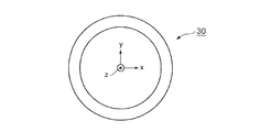
- FIG. 2 is a plan view of the insulator 30 as viewed from the z-axis direction of FIG.
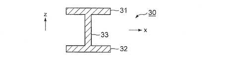
- FIG. 3 is a cross-sectional view of the insulator 30 of FIG. 2 cut along the zx plane.
- FIG. 4 is a side view of the region of the insulator 30 of FIG. 2 near the intersection with the zx plane as viewed from the x-axis direction.
- the insulator 30 is made of a viscoelastic material such as rubber. As shown in FIG. 2, the insulator 30 has a substantially annular shape along the inner peripheral wall of the housing 10, and as shown in FIG. 1, the inner side wall of the housing 10 and the outer wall of the microphone capsule 20 The microphone capsule 20 is supported against the housing 10 while being sandwiched between the two. That is, the insulator 30 is arranged in the space between the inner peripheral wall of the housing 10 and the outer peripheral wall of the microphone capsule 20 (an example of the first region), and the outer peripheral portion of the insulator 30 is supported by the housing 10. The inner peripheral portion of the insulator 30 supports the microphone capsule 20.
- the insulator 30 includes a first horizontal portion 31 and a second horizontal portion 32 shown in FIGS. 3 and 4, a vertical portion 33 (an example of an extension portion), and a vibrating portion 34 (dynamic absorber or vibrating body) shown in FIG. (Example)) is integrally molded.
- Various methods can be considered for molding, and the insulator 30 may be molded by a well-known processing method such as injection molding. That is, the viscoelastic material is heated to a temperature at which it is softened, and the softened material is filled in a mold by applying an appropriate injection pressure to be solidified, thereby molding the insulator 30.
- the first horizontal portion 31 and the second horizontal portion 32 form two annular plates that are separated from each other in the z-axis direction and face each other.
- the vertical portion 33 has a pillar shape extending in the z-axis direction from the upper surface of the second horizontal portion 32 to the lower surface of the first horizontal portion 31, and a plurality of vertical portions 33 are arranged at predetermined intervals along the circumferential direction of the insulator 30.
- Two vibrating portions 34 are provided for each of the plurality of vertical portions 33. These two vibrating portions 34 project like a cantilever from substantially the center of one vertical portion 33 toward both sides in the circumferential direction of the insulator 30.
- the insulator 30 which is a support portion has two rod-shaped vibrating portions 34 protruding from one vertical portion 33 to both sides in the cylindrical direction.
- the vibrating portion 34 can vibrate with respect to other regions of the insulator 30 such as the vertical portion 33, and has a resonance frequency determined by its shape and size. That is, the insulator 30 which is a support portion has a vibrating portion 34 which is one region of the support portion and can vibrate with respect to the other region of the support portion. Since the vibrating unit 34 is arranged in the space between the inner peripheral wall of the housing 10 and the outer peripheral wall of the microphone capsule 20 (an example of the first region), the vibrating body 34 is the inner peripheral wall of the housing 10 and the microphone capsule 20.
- the direction of protrusion of the vibrating portion 34 from the vertical portion 33 is not limited to the circumferential direction with respect to the z-axis direction, and if it protrudes in a direction that does not contact the inner peripheral wall of the housing 10 and the outer peripheral wall of the microphone capsule 20. It may be, for example, a direction orthogonal to the z-axis or a direction intersecting the z-axis.
- the resonance frequency of the vibrating unit 34 is matched with the resonance frequency of the microphone capsule 20, and the vibrating unit 34 functions as a dynamic vibration absorber that absorbs the vibration of the microphone capsule 20.
- the resonance frequency of the vibrating unit 34 is in the range of 50 to 500 Hz.
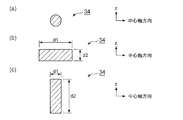
- FIG. 5 (a) to 5 (c) are views showing an example of a cross-sectional shape in which the vibrating portion 34 is cut by a plane orthogonal to the protruding direction thereof, and the vertical direction on the paper surface is the z-axis direction.
- the cross-sectional shape of the vibrating portion 34 is circular.
- the vibrating portion 34 has a uniform elastic modulus with respect to all vibration directions along the cross section. Therefore, a stable vibration suppressing effect can be obtained with respect to a change in the posture of the microphone 1 held by the user.
- the elastic modulus in the central axis direction of the vibrating portion 34 shown in FIG. 5B is higher than the elastic modulus in the z-axis direction.
- the cross-sectional shape of the vibrating portion 34 shown in FIG. 5C is also rectangular, but in this rectangle, the size d1 in the central axis direction is shorter than the size d2 in the z-axis direction. Therefore, the elastic modulus in the z-axis direction of the vibrating portion 34 shown in FIG. 5C is higher than the elastic modulus in the central axis direction.
- the resonance frequency of the vibrating portion 34 is determined by the elastic modulus and mass of the vibrating portion 34.
- the elastic modulus of the vibrating portion 34 depends on the cross-sectional shape of the vibrating portion 34 and the length of the vibrating portion 34 in the protruding direction.
- the mass of the vibrating portion 34 also depends on the cross-sectional shape of the vibrating portion 34 and the length of the vibrating portion 34 in the protruding direction. Therefore, in the present embodiment, it is necessary to determine the cross-sectional shape and the length in the protruding direction of the vibrating portion 34 so that a resonance frequency that matches the resonance frequency of the microphone capsule 20 can be obtained.
- the vibrating portion 34 of the insulator 30 functions as a dynamic vibration absorber.
- a so-called spring mass system is formed by the elasticity and mass of the vibrating portion 34.
- the vibration of the microphone capsule 20 in the vertical vertical direction is suppressed by the resonance of the spring mass system. More specifically, when vibration is transmitted from the hand of the user holding the microphone 1 to the housing 10 and resonance in the z-axis direction is excited by the microphone capsule 20 supported in the housing 10, the vibrating unit 34 moves to the microphone. It resonates with the capsule 20 in the opposite phase. The vibration of the microphone capsule 20 is suppressed by the resonance of the opposite phase of the vibrating portion 34.
- the vibrating portion 34 integrally molded with the other region of the insulator 30 functions as a dynamic vibration absorber to reduce handling noise. Therefore, according to the present embodiment, handling noise can be suppressed without increasing the manufacturing cost of the microphone 1.
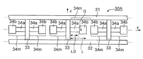
- FIG. 6 is a side view of the insulator 30A according to the second embodiment of the present disclosure as viewed from the x-axis direction of FIG. 1 above.
- FIG. 6 corresponds to FIG. 4 of the first embodiment.
- the insulator 30A has a first horizontal portion 31 and a second horizontal portion 32 and a vertical portion 33 similar to those in the first embodiment, and each 2 protrudes from each vertical portion 33 on both sides in the circumferential direction of the insulator 30A. It has a book vibrating portion 34 m.
- the vibrating portion 34m is composed of a shaft portion 34a on the vertical portion 33 side and a weight portion 34b on the tip side having a larger cross-sectional area than the shaft portion 34a. Then, the vibrating portion 34m has a center of gravity G on the tip side of the position of the length L / 2, which is half the total length L, with the vertical portion 33 as a reference.
- the vibrating portion 34m is integrally molded together with the other region of the insulator 30A.
- the resonance frequency of the vibrating portion 34m can be adjusted by adjusting the position of the center of gravity G of the vibrating portion 34m. Therefore, it becomes easy to match the resonance frequency of the vibrating portion 34m with the resonance frequency of the microphone capsule 20.
- FIG. 7 is a side view of the insulator 30B according to the third embodiment of the present disclosure as viewed from the x-axis direction of FIG. 1 above.
- FIG. 7 corresponds to FIG. 4 of the first embodiment.
- This insulator 30B has a first horizontal portion 31 and a second horizontal portion 32, a vertical portion 33, and vibration portions 34c and 34d, which are the same as those in the first embodiment.
- the vibrating portions 34c and 34d project from each vertical portion 33 on one side in the circumferential direction of the insulator 30B, and the vibrating portions 34c and 34d project on the other side in the circumferential direction of the insulator 30B.
- the vibrating portions 34c and 34d are integrally molded together with other regions of the insulator 30B.
- the protruding length of the vibrating portion 34c from the vertical portion 33 is longer than the protruding length of the vibrating portion 34d from the vertical portion 33. Therefore, the resonance frequency of the vibrating unit 34c deviates from the resonance frequency of the vibrating unit 34d.
- the resonance Q of the vibrating portion is sharper than that of the resonance Q of the microphone capsule 20, and if the vibrating portion corresponding to one type of resonance frequency is provided, the resonance of the microphone capsule 20 is effective. It is effective when it is difficult to attenuate the frequency.
- the resonance characteristics of the two types of vibrating portions 34c and 34d cover the frequency band in which the resonance peak of the microphone capsule 20 occurs.
- the resonance of the microphone capsule 20 is sharp even when the resonance Q of the vibrating portion is sharp with respect to the resonance Q of the microphone capsule 20. Can be effectively dampened.
- two types of vibrating portions having different lengths are provided, but three or more types of vibrating portions having different lengths may be provided.
- FIG. 8 is a side view of the insulator 30C according to the fourth embodiment of the present disclosure as viewed from the x-axis direction of FIG. 1 above.
- FIG. 8 corresponds to FIG. 4 of the first embodiment.
- This insulator 30C has a first horizontal portion 31 and a second horizontal portion 32, a vertical portion 33, and a vibrating portion 34n, which are the same as those in the first embodiment.
- the vibrating portion in the first to third embodiments was a cantilever with one end fixed to the vertical portion 33 and the other end free.
- the vibrating portion 34n in the present embodiment is a double-sided beam in which both ends are fixed, specifically, both ends are fixed to two vertical portions 33 which are separated from each other and adjacent to each other. That is, in the present embodiment, the insulator 30C, which is a support portion, includes a first extension portion (one vertical portion 33) and a second extension portion (adjacent vertical portion 33), and is the first.
- a vibrating portion 34n is provided between the extension portion and the second extension portion. Similar to the first embodiment, in this embodiment as well, the vibrating portion 34n is integrally molded together with the other region of the insulator 30C. Further, as in the first embodiment, the vibrating unit 34n functions as a dynamic vibration absorber.
- one vibrating portion 34n includes a weight portion 34g located at the center between the two vertical portions 33 and two shafts extending from the weight portion 34b to the two vertical portions 33. It has parts 34e and 34f.
- the cross-sectional area of the weight portion 34b is larger than the cross-sectional area of the shaft portions 34e and 34f.
- the weight portion 34b is arranged in a space (an example of the first region) formed between the inner peripheral wall of the housing 10 and the outer peripheral wall of the microphone capsule 20, the inner peripheral wall of the housing 10 and the microphone capsule 20 are arranged. It can vibrate freely without touching the outer wall of the.
- the vibrating portion 34n which is one region of the insulator 30B, can vibrate with respect to another region of the insulator 30B such as the vertical portion 33.
- the vibrating unit 34n has the same resonance frequency as the microphone capsule 20. Therefore, also in this embodiment, the resonance of the microphone capsule 20 can be attenuated by the vibrating unit 34n. Further, since both ends of the vibrating portion 34n in the present embodiment are fixed to the vertical portion 33, fatigue generated in the boundary region between the vibrating portion 34n and the vertical portion 33 can be reduced.
- FIG. 9 is a perspective view showing the configuration of the model M1 used in the simulation.
- FIG. 10 is a perspective view showing the configuration of the model M2 used in the simulation.
- Model M1 is an insulator composed of an annular first horizontal portion 31 and a second horizontal portion 32 and having no dynamic vibration absorber.
- the model M2 is composed of an annular first horizontal portion 31 and a second horizontal portion 32, and an intermediate member 35 provided between them.
- the intermediate member 35 includes a vibrating portion that functions as a dynamic vibration absorber.
- the first horizontal portion 31 and the second horizontal portion 32 of the models M1 and M2 are fixed at intervals in the z-axis direction while being sandwiched between the inner wall surface of the housing 10 and the outer wall surface of the microphone capsule 20. (See FIG. 1).
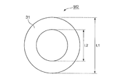
- FIG. 11 is a plan view of the model M2 viewed from above in the vertical direction.
- FIG. 12 is a plan view of the intermediate member 35 viewed from above in the vertical direction with the first horizontal portion 31 removed.
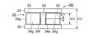
- FIG. 13 is a side view of the model M2.
- the first horizontal portion 31 of the model M2 has an annular shape with an outer diameter L1 of 36 mm and an inner diameter L2 of 20.1 mm.
- the second horizontal portion 32 also has the same shape as the first horizontal portion 31.
- the first horizontal portion 31 and the second horizontal portion 32 of the model M1 also have the same shape as the first horizontal portion 31 shown in FIG.
- Model M2 corresponds to the insulator of the fourth embodiment.
- the intermediate member 35 of the model M2 has four vertical portions 33 extending from the upper surface of the second horizontal portion 32 to the lower surface of the first horizontal portion 31, and two adjacent vertical portions 33. It has four vibrating portions 34n, each of which is provided between the portions 33.
- the vibrating portion 34n functions as a dynamic vibration absorber.
- one vibrating portion 34n has a weight portion 34g and two shaft portions 34e and 34f extending from the weight portion 34b to two vertical portions 33.
- the shaft portions 34e and 34d have a thickness d11 in the z-axis direction of 0.2 mm, a width w11 in the radial direction (direction of the diameter of the annular insulator) of 4 mm, and a circumferential direction (circle).
- the length d21 in the circumferential direction of the ring-shaped insulator is 1.77 mm.
- the weight portion 34 g has a thickness d12 in the z-axis direction of 11 mm, a width w12 in the radial direction of 6 mm, and an angle ⁇ between both ends in the circumferential direction of 70 °.
- the height d13 from the lower surface of the second horizontal portion 32 to the upper surface of the first horizontal portion 31 is 20 mm.
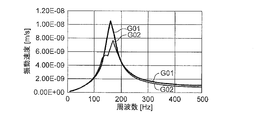
- FIG. 14 shows the results of simulating each of the microphone 1 to which the model M1 is applied and the microphone 1 to which the model M2 is applied.
- the vertical axis in FIG. 14 is a coordinate axis representing a common logarithmic value of the vibration velocity of the evaluation surface when the upper surface S1 of the microphone capsule 20 is used as an evaluation surface
- the horizontal axis is a coordinate axis representing a frequency.
- the frequency characteristic G01 shows the relationship between the vibration speed and the frequency of the evaluation surface of the microphone 1 to which the model M1 is applied
- the frequency characteristic G02 shows the vibration of the evaluation surface of the microphone 1 to which the model M2 is applied. It shows the relationship between speed and frequency.
- a resonance peak occurs in the vicinity of 160 Hz due to the spring mass system formed by the housing 10, the model M1, and the microphone capsule 20.
- the frequency characteristic G02 when the model M2 is used in the vicinity of 160 Hz, the resonance of the spring mass system and the resonance of the opposite phase occur in the vibrating portion 34n of the intermediate member 35, and the resonance of the opposite phase causes resonance. The peak decreases. In this way, it was confirmed that the amount of handling noise generated in the microphone capsule 20 was reduced by the vibrating unit 34n.
- the model M2 corresponding to the insulator of the fourth embodiment is used, but since the insulators of the other embodiments are basically based on the same principle as the fourth embodiment, the above The same effect as the model M2 can be expected.
- the technique of shifting the resonance peak by the low-order vibration mode to a frequency lower than the lower limit of the audible band and the technique disclosed in each of the above embodiments may be used in combination.
- the resonance peak due to the low-order vibration mode is shifted to a frequency lower than the lower limit of the audible band by a measure such as making the microphone capsule heavier or loosening the support of the microphone capsule by the insulator.
- the insulator is provided with a vibrating portion having a resonance frequency that matches the frequency of the resonance peak after the shift.
- the resonance peak due to the low-order vibration mode is shifted to a frequency lower than the lower limit of the audible band, and the resonance peak after this shift is reduced by the vibrating portion, so that the influence of handling noise is more reliable. Can be suppressed.
- the handling noise having an amplitude in the vertical direction is reduced by the vibrating portion protruding in the horizontal direction with respect to the insulator.
- the protruding direction of the vibrating portion is not limited to this.
- a vibrating portion protruding in the vertical direction may be provided with respect to the insulator, and the vibrating portion may reduce handling noise having an amplitude in the horizontal direction.
- the insulator in a state where the microphone is gripped along the vertical direction, the insulator is provided with a vibrating part protruding in the horizontal direction and a vibrating part protruding in the vertical direction protruding in the vertical direction, and these two types of vibrating parts provide a vibrating part in the vertical direction.
- the handling noise having an amplitude and the handling noise having an amplitude in the horizontal direction may be reduced.
- the vibrating portion and the other region of the insulator are integrally molded, but the vibrating portion and the other region may be manufactured separately and the two may be combined.
- the vibrating portion and another region of the insulator may be fixed with an adhesive.
- the vibrating portion may be screwed to another region of the insulator.
- the vibrating portion and other regions of the insulator are made of the same material, but both may be made of different materials.
- the weight portions 34b and 34g and the shaft portions 34a, 34e and 34f are made of the same material, but may be different materials.
- the shaft portions 34a, 34e and 34f may be made of rubber, and the weight portions 34b and 34g may be made of metal.
- the shaft portions 34a, 34e and 34f may be made of metal, and the weight portions 34b and 34g may be made of rubber.
- a plurality of vibrating portions 34n may be provided between adjacent vertical portions 33.
- the mass of the weight portion 34g may be different among the plurality of vibrating portions 34n.
- the resonance frequency of the dynamic vibration absorber may be appropriately determined according to the noise band to be vibration-absorbed.
- the resonance frequency of the dynamic vibration absorber is in the range of 20 to 20000 Hz. In a more preferred embodiment, the resonance frequency of the dynamic vibration absorber is in the range of 50 to 1000 Hz.
- Microphone, 10 ... Housing, 20 ... Microphone capsule, 30 ... Insulator, 40 ... Windshield, 31 ... 1st horizontal part, 32 ... 2nd horizontal part, 33 ... Vertical part, 34,34m, 34n, 34c, 34d ... Vibrating part, 34a, 34e, 34f ... Shaft part, 34b, 34g ... Weight part, 35 ... Intermediate member, M1, M2 ... Model.
Landscapes
- Physics & Mathematics (AREA)
- Engineering & Computer Science (AREA)
- Acoustics & Sound (AREA)
- Signal Processing (AREA)
- Details Of Audible-Bandwidth Transducers (AREA)
Abstract
製造コストの増加を招くことなく、ハンドリングノイズを低減することが可能なマイクロホンを提供する。 筐体10と、筐体10内に設けられるマイクカプセル20と、マイクカプセル20と筐体10とに取り付けられるインシュレータ30と、インシュレータ30に設けられた突出する振動部34とを有する。振動部34は、動吸振器として機能する。
Description
本開示は、マイクロホンに関する。
マイクロホンにおいては、音と当該音の波形を表す電気信号(以下、音信号)の相互変換を行うマイクカプセルに外部からの加振等による振動が伝わることでノイズが発生することがある。このようなノイズの具体例としては、ハンドヘルドタイプのマイクロホンにおけるハンドリングノイズが挙げられる。ハンドリングノイズは、マイクロホンを持つ手からマイクロホンの筐体に振動が伝わり、筐体内に支持されたマイクカプセルにその振動が伝わることで、その振動成分を含む音信号が出力され、発生する。
ハンドリングノイズの発生を抑制するために、ゴムなどの弾性材料で形成されたインシュレータを介在させて筐体に対してマイクカプセルを支持する構造が提案されている。例えば、特許文献1には、電気粘性流体を含むダンパによりマイクカプセルを弾性的に支持する構造が開示されている。特許文献1に開示のマイクロホンでは、本体に衝撃が加わると、圧電素子が変形して発電し、粘性流体に電圧が印加されて硬くなる。その結果、マイクカプセルの過大な変位が抑えられるという効果を奏する。
しかしながら、特許文献1に開示の技術を採用したとしても、マイクロホンの本体に加わる衝撃によりマイクカプセルの共振が発生することに変わりはなく、マイクカプセルの出力信号にこの共振の周波数に応じたピークが残ることは変わりない。
一方、ハンドリングノイズ対策には、低次の振動モードによる共振ピークが20Hz~20kHzの可聴帯域に現れないようにする対策もあり、当該共振ピークを可聴帯域の下限よりも低い周波数にシフトさせる方策も種々提案されている。その一例としては、マイクカプセルを重くする、或いはインシュレータによるマイクカプセルの支持を緩くするといった方策が挙げられる。
しかしながら、マイクカプセルを重くする、或いはインシュレータによるマイクカプセルの支持を緩くするといった方策では、マイクカプセルの保持性能が低下し、マイクロホンの製品品質を担保できなくなるといった問題がある。
本開示は以上に説明した課題に鑑みて為されたものであり、簡易な構造でハンドリングノイズを低減することが可能なマイクロホンを提供することを目的とする。
この開示は、筐体と、前記筐体内に設けられるマイクカプセルと、前記マイクカプセルと前記筐体とに取り付けられる支持部と、前記支持部に設けられた動吸振器とを有することを特徴とするマイクロホンを提供する。
また、別な観点のマイクロホンとして、筐体と、前記筐体内に設けられるマイクカプセルと、前記マイクカプセルと前記筐体とに取り付けられる支持部とを具備し、前記支持部は、離間して互いに隣り合う第1の延設部と第2の延設部を含み、かつ、前記第1の延設部および前記第2の延設部間に動吸振器を有し、前記動吸振器は、両端部が前記第1の延設部及び前記第2の延設部に支持されるマイクロホンが提供される。
また、別の観点のマイクロホンとして、円筒形状の筐体と、前記筐体内に設けられるマイクカプセルと、前記マイクカプセルを前記筐体に弾性的に支持する支持部と、を備え、前記支持部は、前記筐体の内周壁と前記マイクカプセルの外周壁の間の第1領域に設けられ、振動可能な振動体を有するマイクロホンが提供される。
また、別な観点のマイクロホンとして、筐体と、前記筐体内に設けられるマイクカプセルと、前記マイクカプセルと前記筐体とに取り付けられる支持部とを具備し、前記支持部は、離間して互いに隣り合う第1の延設部と第2の延設部を含み、かつ、前記第1の延設部および前記第2の延設部間に動吸振器を有し、前記動吸振器は、両端部が前記第1の延設部及び前記第2の延設部に支持されるマイクロホンが提供される。
また、別の観点のマイクロホンとして、円筒形状の筐体と、前記筐体内に設けられるマイクカプセルと、前記マイクカプセルを前記筐体に弾性的に支持する支持部と、を備え、前記支持部は、前記筐体の内周壁と前記マイクカプセルの外周壁の間の第1領域に設けられ、振動可能な振動体を有するマイクロホンが提供される。
以下、図面を参照しつつ本開示の実施形態を説明する。
(A:第1実施形態)
図1は、この開示の第1実施形態によるマイクロホン1の構成例を示す部分断面図である。マイクロホン1は、略円筒形の形状を有するハンドヘルド型マイクロホンである。図1では、マイクロホン1の中心軸に平行なz軸と、z軸に対して直交する平面内において互いに直交するx軸およびy軸からなる右ねじの直交座標系を想定している。そして、図1はz軸を含む平面によるマイクロホン1のマイクヘッド部の断面図である。図1に示すように、マイクロホン1は、筐体10と、マイクカプセル20と、マイクカプセル20と筐体10とに取り付けられる支持部であるインシュレータ30と、マイクカプセル20を覆う風防40とを有する。
図1は、この開示の第1実施形態によるマイクロホン1の構成例を示す部分断面図である。マイクロホン1は、略円筒形の形状を有するハンドヘルド型マイクロホンである。図1では、マイクロホン1の中心軸に平行なz軸と、z軸に対して直交する平面内において互いに直交するx軸およびy軸からなる右ねじの直交座標系を想定している。そして、図1はz軸を含む平面によるマイクロホン1のマイクヘッド部の断面図である。図1に示すように、マイクロホン1は、筐体10と、マイクカプセル20と、マイクカプセル20と筐体10とに取り付けられる支持部であるインシュレータ30と、マイクカプセル20を覆う風防40とを有する。
筐体10は、樹脂或いは金属で円筒状に形成された部材である。マイクロホン1を使用する際には、ユーザは、z軸が鉛直方向に向き、風防40が鉛直上方向に向くように筐体10を把持する。風防40は、マイクカプセル20を保護するための部材であり、例えば金属メッシュで形成されている。風防40は、外部から到来する音を当該風防40と筐体10とにより区画される内部空間へ透過させる。図1に示すように、この内部空間にはインシュレータ30によってマイクカプセル20が支持されている。
マイクカプセル20は、筐体10よりも径の小さい略円筒形に形成された部材である。マイクカプセル20は、合成樹脂または金属で形成された振動板と、外部から到来する音により励起された振動板の振動を音信号に変換して出力する電気音響変換器とを含む。図1では振動板および電気音響変換器の図示は省略されている。電気音響変換器の構成は従来のマイクカプセルにおけるものを用いることができ、具体的には、電気音響変換器は、振動板に接続されたボイスコイル、当該ボイスコイルと鎖交する磁界を発生させるマグネットおよびヨークを含む。
次にインシュレータ30について説明する。図2はインシュレータ30を図1のz軸方向から見た平面図である。図3は図2のインシュレータ30をz-x平面により切断した断面図である。また、図4は、図2のインシュレータ30のz-x平面との交差部付近の領域をx軸方向から見た側面図である。
インシュレータ30は、ゴムなどの粘弾性材料により構成されている。インシュレータ30は、図2に示すように全体として筐体10の内周壁に沿う略円環形状をなしており、図1に示すように、筐体10の内側壁とマイクカプセル20の外側壁との間に挟まれた状態で、筐体10に対してマイクカプセル20を支持する。つまり、インシュレータ30は、筐体10の内周壁とマイクカプセル20の外周壁の間の空間(第1領域の一例)に配置されており、インシュレータ30の外周部は、筐体10に支持され、インシュレータ30の内周部は、マイクカプセル20を支持している。
インシュレータ30は、図3および図4に示す第1水平部31および第2水平部32と、垂直部33(延設部の一例)と、図4に示す振動部34(動吸収器または振動体の一例)とを一体成形してなるものである。成形に関しては、各種の方法が考えられるが、例えば射出成形等の周知の加工法によりインシュレータ30を成形してもよい。すなわち、粘弾性材料を軟化する温度までに加熱し、軟化した材料を適度な射出圧を加えて金型に充填して固化させ、インシュレータ30を成形するのである。
インシュレータ30において、第1水平部31および第2水平部32は、z軸方向に離れて互いに向き合った2枚の円環板状をなしている。垂直部33は、第2水平部32の上面から第1水平部31の下面までz軸方向に延びた柱形状をなしており、インシュレータ30の円周方向に沿って所定間隔を空けて複数配置されている。複数の垂直部33の各々には、2個の振動部34が設けられている。これらの2個の振動部34は、1個の垂直部33の略中央付近からインシュレータ30の円周方向両側に向けて片持ち梁状に突出している。このように本実施形態において、支持部であるインシュレータ30は、1つの垂直部33から円柱方向両側へ突出する棒形状の2つの振動部34を有する。この振動部34は、垂直部33等、インシュレータ30の他の領域に対して振動可能であり、その形状およびサイズにより定まる共振周波数を有する。すなわち、支持部であるインシュレータ30は、支持部の一の領域であって、支持部の他の領域に対して振動可能な振動部34を有する。振動部34は、筐体10の内周壁とマイクカプセル20の外周壁の間の空間(第1領域の一例)に配置されるため、振動体34は、筐体10の内周壁及びマイクカプセル20の外周壁に接触することなく、自由に振動することができる。なお、振動部34の垂直部33からの突出方向は、z軸方向に対する円周方向に限られるものでは無く、筐体10の内周壁及びマイクカプセル20の外周壁に接触しない方向に突出すれば良く、例えば、z軸に直交する方向であっても良いし、z軸と交差する方向であっても良い。
本実施形態では、マイクカプセル20の共振周波数に対して、振動部34の共振周波数を合わせ、振動部34を、マイクカプセル20の振動を吸収する動吸振器として機能させる。本実施形態において、振動部34の共振周波数は、50~500Hzの範囲内にある。
図5(a)~(c)は振動部34をその突出方向に対して直交する平面により切断した断面形状の例を示す図であり、紙面における上下方向がz軸方向である。図5(a)に示す例において、振動部34の断面形状は円形である。この振動部34は、断面に沿った全振動方向に対する弾性率が均一である。従って、ユーザが把持するマイクロホン1の姿勢の変化に対して安定した振動抑制効果が得られる。図5(b)に示す振動部34の断面形状は矩形であり、この矩形は、マイクロホン1の中心軸方向のサイズd1がz軸方向のサイズd2よりも長い。このため、図5(b)に示す振動部34は、中心軸方向の弾性率がz軸方向の弾性率よりも高い。図5(c)に示す振動部34の断面形状も矩形であるが、この矩形は、中心軸方向のサイズd1がz軸方向のサイズd2よりも短い。このため、図5(c)に示す振動部34は、z軸方向の弾性率が中心軸方向の弾性率よりも高い。
本実施形態では、振動部34の共振周波数をマイクカプセル20の共振周波数に合わせる必要がある。この振動部34の共振周波数は、振動部34の弾性率と質量により定まる。そして、振動部34の弾性率は、振動部34の断面形状の他、振動部34の突出方向の長さに依存する。また、振動部34の質量も、振動部34の断面形状および振動部34の突出方向の長さに依存する。従って、本実施形態では、マイクカプセル20の共振周波数と一致した共振周波数が得られるように、振動部34の断面形状および突出方向の長さを決定する必要がある。
本実施形態において、ユーザは、マイクロホン1を使用する際に、風防40が鉛直上方向に向くように筐体10を把持する。この状態において、インシュレータ30の振動部34は、動吸振器として機能する。この動吸振器では、振動部34の弾性と質量とにより、所謂バネマス系が形成される。本実施形態では、このバネマス系の共振によりマイクカプセル20の鉛直上下方向の振動が抑制される。より具体的には、マイクロホン1を持つユーザの手から筐体10に振動が伝わり、筐体10内に支持されたマイクカプセル20にz軸方向の共振が励起されると、振動部34がマイクカプセル20と逆位相で共振する。この振動部34の逆位相の共振により、マイクカプセル20の振動が抑制される。
以上説明したように、本実施形態では、インシュレータ30の他の領域と一体成形された振動部34が動吸振器として機能し、ハンドリングノイズを低減させる。従って、本実施形態によれば、マイクロホン1の製造コストの増加を招くことなく、ハンドリングノイズを抑制することができる。
(B:第2実施形態)
図6はこの開示の第2実施形態におけるインシュレータ30Aを前掲図1のx軸方向から見た側面図である。この図6は上記第1実施形態の図4に相当するものである。
図6はこの開示の第2実施形態におけるインシュレータ30Aを前掲図1のx軸方向から見た側面図である。この図6は上記第1実施形態の図4に相当するものである。
このインシュレータ30Aは、上記第1実施形態と同様な第1水平部31および第2水平部32と、垂直部33を有するとともに、各垂直部33からインシュレータ30Aの円周方向両側に突出した各2本の振動部34mを有する。この振動部34mは、垂直部33側の軸部34aとこの軸部34aよりも断面積が大きい先端側の錘部34bとにより構成されている。そして、振動部34mは、垂直部33を基準として、全長Lの半分の長さL/2の位置よりも先端側に重心Gを有する。上記第1実施形態と同様、本実施形態においても、振動部34mは、インシュレータ30Aの他の領域とともに一体成形される。本実施形態においても上記第1実施形態と同じ効果が得られる。また、本実施形態によれば、振動部34mの重心Gの位置の調整により振動部34mの共振周波数を調整することができる。従って、振動部34mの共振周波数をマイクカプセル20の共振周波数に合わせることが容易になる。
(C:第3実施形態)
図7はこの開示の第3実施形態におけるインシュレータ30Bを前掲図1のx軸方向から見た側面図である。この図7は上記第1実施形態の図4に相当するものである。
図7はこの開示の第3実施形態におけるインシュレータ30Bを前掲図1のx軸方向から見た側面図である。この図7は上記第1実施形態の図4に相当するものである。
このインシュレータ30Bは、上記第1実施形態と同様な第1水平部31および第2水平部32と、垂直部33を有するとともに、振動部34cおよび34dを有する。本実施形態では、各垂直部33からインシュレータ30Bの円周方向の一方側に振動部34cおよび34dが突出し、インシュレータ30Bの円周方向の他方側に振動部34cおよび34dが突出している。上記第1実施形態と同様、本実施形態においても、振動部34cおよび34dは、インシュレータ30Bの他の領域とともに一体成形される。ここで、振動部34cの垂直部33からの突出長は、振動部34dの垂直部33からの突出長よりも長い。このため、振動部34cの共振周波数は、振動部34dの共振周波数からずれている。
本実施形態は、例えばマイクカプセル20の共振のQに比べて、振動部の共振のQが鋭く、1種類の共振周波数に対応した振動部を設けたのでは、マイクカプセル20の共振を効果的に減衰させるのが困難な場合に有効である。具体的には、2種類の振動部34cおよび34dの共振特性によりマイクカプセル20の共振のピークが発生する周波数帯域をカバーするのである。本実施形態によれば、長さの異なる2種類の振動部34cおよび34dを設けたので、マイクカプセル20の共振のQに対して振動部の共振のQが鋭い場合でも、マイクカプセル20の共振を効果的に減衰させることができる。なお、本実施形態では、長さの異なる2種類の振動部を設けたが、長さの異なる3種類以上の振動部を設けてもよい。
(D:第4実施形態)
図8はこの開示の第4実施形態におけるインシュレータ30Cを前掲図1のx軸方向から見た側面図である。この図8は上記第1実施形態の図4に相当するものである。
図8はこの開示の第4実施形態におけるインシュレータ30Cを前掲図1のx軸方向から見た側面図である。この図8は上記第1実施形態の図4に相当するものである。
このインシュレータ30Cは、上記第1実施形態と同様な第1水平部31および第2水平部32と、垂直部33を有するとともに、振動部34nを有する。上記第1~第3実施形態における振動部は、一端が垂直部33に固定された固定端、他端が自由端である片持ち梁であった。これに対し、本実施形態における振動部34nは、両端が固定端、具体的には離間して互いに隣合った2つの垂直部33に両端が固定された両持ち梁である。すなわち、本実施形態において、支持部であるインシュレータ30Cは、第1の延設部(1つの垂直部33)と第2の延設部(隣の垂直部33)を含み、かつ、第1の延設部および第2の延設部間に振動部34nを有する。上記第1実施形態と同様、本実施形態においても、振動部34nは、インシュレータ30Cの他の領域とともに一体成形される。また、上記第1実施形態と同様、振動部34nは、動吸振器として機能する。
図8に示すように、1個の振動部34nは、2個の垂直部33間の中央に位置する錘部34gと、この錘部34bから2個の垂直部33まで延びた2本の軸部34eおよび34fとを有する。ここで、錘部34bの断面積は軸部34eおよび34fの断面積よりも大きい。また、錘部34bは、筐体10の内周壁とマイクカプセル20の外周壁の間に形成された空間(第1領域の一例)に配置されるため、筐体10の内周壁とマイクカプセル20の外周壁に接触することなく、自由に振動することができる。
本実施形態においても、インシュレータ30Bの一の領域である振動部34nは、垂直部33等のインシュレータ30Bの他の領域に対して振動可能である。そして、振動部34nは、マイクカプセル20と同じ共振周波数を有する。従って、本実施形態においてもマイクカプセル20の共振を振動部34nにより減衰させることができる。また、本実施形態における振動部34nは、両端が垂直部33に固定されているので、振動部34nと垂直部33との境界領域に発生する疲労を少なくすることができる。
(E:効果の確認)
本願発明者は、上記各実施形態の効果を確認するために、2つのインシュレータのモデルを想定し、マイクカプセルに発生する振動の周波数特性をシミュレーションにより求めた。図9はシミュレーションに用いたモデルM1の構成を示す斜視図である。また、図10はシミュレーションに用いたモデルM2の構成を示す斜視図である。
本願発明者は、上記各実施形態の効果を確認するために、2つのインシュレータのモデルを想定し、マイクカプセルに発生する振動の周波数特性をシミュレーションにより求めた。図9はシミュレーションに用いたモデルM1の構成を示す斜視図である。また、図10はシミュレーションに用いたモデルM2の構成を示す斜視図である。
モデルM1は、円環状の第1水平部31および第2水平部32からなり、動吸振器を有しないインシュレータである。モデルM2は、円環状の第1水平部31および第2水平部32と、これらの間に設けられた中間部材35とにより構成されている。この中間部材35は、動吸振器として機能する振動部を含む。モデルM1およびM2の第1水平部31および第2水平部32は、筐体10の内壁面とマイクカプセル20の外壁面との間に挟まれた状態で、z軸方向に間隔を空けて固定される(図1参照)。
図11は鉛直方向上方から見たモデルM2の平面図である。図12は第1水平部31を取り除いて鉛直方向上方から見た中間部材35の平面図である。また、図13はモデルM2の側面図である。
図11において、モデルM2の第1水平部31は、外径L1が36mm、内径L2が20.1mmの円環形状を有する。第2水平部32も、第1水平部31と同じ形状を有する。また、モデルM1の第1水平部31および第2水平部32も、図11に示す第1水平部31と同じ形状を有する。
モデルM2は、上記第4実施形態のインシュレータに相当する。図12および図13に示すように、モデルM2の中間部材35は、第2水平部32の上面から第1水平部31の下面まで延びた4本の垂直部33と、隣り合う2本の垂直部33間に各々設けられた4個の振動部34nとを有する。この振動部34nが動吸振器として機能する。上記第4実施形態において説明したように、1個の振動部34nは、錘部34gと、この錘部34bから2個の垂直部33まで延びた2本の軸部34eおよび34fとを有する。モデルM2において、軸部34eおよび34dは、z軸方向の厚さd11が0.2mmであり、径方向(円環形状のインシュレータの径の方向)の幅w11が4mmであり、周方向(円環形状のインシュレータの周方向)の長さd21が1.77mmである。錘部34gは、z軸方向の厚さd12が11mmであり、径方向の幅w12が6mmであり、周方向両端間の角度θが70°である。また、モデルM1およびM2において、第2水平部32の下面から第1水平部31の上面までの高さd13は20mmである。
図14は、モデルM1を適用したマイクロホン1とモデルM2を適用したマイクロホン1の各々についてシミュレーションを行った結果を示すものである。図14における縦軸は、マイクカプセル20の上面S1を評価面とした場合における当該評価面の振動速度の常用対数値を表す座標軸であり、横軸は周波数を表す座標軸である。
図14において、周波数特性G01は、モデルM1を適用したマイクロホン1についての評価面の振動速度と周波数の関係を示しており、周波数特性G02は、モデルM2を適用したマイクロホン1についての評価面の振動速度と周波数の関係を示している。
モデルM1を使用した場合の周波数特性G01では、筐体10とモデルM1とマイクカプセル20とがなすバネマス系により160Hz付近に共振のピークが発生する。これに対し、モデルM2を使用した場合の周波数特性G02では、160Hz付近において、中間部材35の振動部34nに上記バネマス系の共振と逆相の共振が発生し、この逆相の共振により共振のピークが減少する。このようにマイクカプセル20に発生するハンドリングノイズ量が振動部34nにより低減されることが確認された。
以上説明したシミュレーションでは、上記第4実施形態のインシュレータに相当するモデルM2を用いたが、他の実施形態のインシュレータも、基本的に上記第4実施形態と同じ原理に基づくものであるため、上記モデルM2と同様な効果を期待することができる。
(F:他の実施形態)
以上、この開示の各実施形態について説明したが、この開示には他にも実施形態が考えられる。例えば次の通りである。
以上、この開示の各実施形態について説明したが、この開示には他にも実施形態が考えられる。例えば次の通りである。
(1)低次の振動モードによる共振ピークを可聴帯域の下限よりも低い周波数にシフトさせる技術と、上記各実施形態に開示された技術とを併用してもよい。具体的には、マイクカプセルを重くする、或いはインシュレータによるマイクカプセルの支持を緩くするといった方策により、低次の振動モードによる共振ピークを可聴帯域の下限よりも低い周波数にシフトさせる。そして、このシフト後の共振ピークの周波数と一致する共振周波数を有する振動部をインシュレータに設けるのである。この態様によれば、低次の振動モードによる共振ピークを可聴帯域の下限よりも低い周波数にシフトさせ、かつ、このシフト後の共振ピークを振動部により低減するので、より確実にハンドリングノイズの影響を抑制することができる。
(2)上記各実施形態では、マイクロホンが鉛直方向に沿うように把持された状態において、インシュレータに対して水平方向に突出した振動部により鉛直方向に振幅を持ったハンドリングノイズを低減した。しかし、振動部の突出方向はこれに限定されるものではない。マイクロホンが鉛直方向に沿うように把持された状態において、インシュレータに対して鉛直方向に突出した振動部を設け、この振動部により水平方向に振幅を持ったハンドリングノイズを低減してもよい。あるいはマイクロホンが鉛直方向に沿うように把持された状態において、水平方向に突出した振動部と鉛直方向に突出した鉛直方向に突出した振動部をインシュレータに設け、これら2種類の振動部により、鉛直方向に振幅を持ったハンドリングノイズと水平方向に振幅を持ったハンドリングノイズを低減してもよい。
(3)上記各実施形態では、インシュレータにおける振動部と他の領域とを一体成形したが、振動部と他の領域を別々に製造し、両者を結合してもよい。例えば振動部とインシュレータの他の領域とを接着剤により固定してもよい。あるいは振動部をインシュレータの他の領域にねじ止めしてもよい。また、上記各実施形態では、インシュレータにおける振動部と他の領域を同じ素材により構成したが、両者を異なる素材により構成してもよい。
(4)上記第2実施形態(図6)および第4実施形態(図8)において、錘部34bおよび34gと、軸部34a、34eおよび34fは、同一素材であったが、異なる素材としてもよい。例えば軸部34a、34eおよび34fをゴムとし、錘部34bおよび34gを金属としてもよい。逆に軸部34a、34eおよび34fを金属とし、錘部34bおよび34gをゴムとしてもよい。
(5)上記第4実施形態(図8)において、隣り合う垂直部33間に振動部34nを複数設けてもよい。この場合において、複数の振動部34n間で錘部34gの質量を異ならせてもよい。
(6)動吸振器の共振周波数は、吸振対象であるノイズの帯域に合わせて適宜決定すればよい。好ましい態様において、動吸振器の共振周波数は、20~20000Hzの範囲内である。より好ましい態様において、動吸振器の共振周波数は、50~1000Hzの範囲内である。
1…マイクロホン、10…筐体、20…マイクカプセル、30…インシュレータ、40…風防、31…第1水平部、32…第2水平部、33…垂直部、34,34m,34n,34c,34d…振動部、34a,34e,34f…軸部、34b,34g…錘部、35…中間部材、M1,M2…モデル。
Claims (19)
- 筐体と、
前記筐体内に設けられるマイクカプセルと、
前記マイクカプセルと前記筐体とに取り付けられる支持部と、
前記支持部に設けられた動吸振器と、を有するマイクロホン。 - 前記動吸振器は棒状であり、弾性を有する請求項1に記載のマイクロホン。
- 前記動吸振器は、全長の半分の位置よりも先端側に重心を有する請求項1または2に記載のマイクロホン。
- 前記動吸振器は、先端に錘を有する請求項1~3のいずれか1項に記載のマイクロホン。
- 前記動吸振器を複数有する請求項1~4のいずれか1項に記載のマイクロホン。
- 前記複数の動吸振器のうち、少なくとも長さの異なる組が1組存在する請求項5に記載のマイクロホン。
- 筐体と、
前記筐体内に設けられるマイクカプセルと、
前記マイクカプセルと前記筐体とに取り付けられる支持部とを具備し、
前記支持部は、離間して互いに隣り合う第1の延設部と第2の延設部を含み、かつ、前記第1の延設部および前記第2の延設部間に動吸振器を有し、前記動吸振器は、両端部が前記第1の延設部及び前記第2の延設部に支持されるマイクロホン。 - 前記動吸振器の共振周波数は、20~20000Hzである請求項1~7のいずれか1項に記載のマイクロホン。
- 前記動吸振器の共振周波数は、50~1000Hzである請求項1~8のいずれか1項に記載のマイクロホン。
- 前記筐体は、円筒形状であり、
前記支持部は、前記筐体の内周壁に沿う円環形状であり、
前記動吸振器は、前記支持部より円周方向に突出する請求項1~9のいずれか1項に記載のマイクロホン。 - 前記動吸振器は、片持ち梁状に突出するものである請求項10に記載のマイクロホン。
- 円筒形状の筐体と、
前記筐体内に設けられるマイクカプセルと、
前記マイクカプセルを前記筐体に弾性的に支持する支持部と、を備え、
前記支持部は、前記筐体の内周壁と前記マイクカプセルの外周壁の間の第1領域に設けられ、振動可能な振動体を有するマイクロホン。 - 前記支持部は、前記第1領域に設けられ、前記筐体の軸方向に略平行な第1方向に延びる延設部を有し、
前記振動体は、前記延設部に設けられる請求項12に記載のマイクロホン。 - 前記振動体は、前記第1領域において、前記延設部から前記第1方向に交差する方向に延出する請求項13に記載のマイクロホン。
- 前記支持部は、前記筐体の内周壁に沿う円環形状であり、
前記振動体は、前記延設部から円周方向に突出する請求項13又は14に記載のマイクロホン。 - 前記振動体は、前記延設部から片持ち梁状に突出するものである請求項13~15のいずれか1項に記載のマイクロホン。
- 前記振動体は、前記延設部と一体的に形成される請求項13~16のいずれか1項に記載のマイクロホン。
- 前記振動部は、前記延設部としての複数の延設部のうちの互いに隣り合う2つである第1延設部から第2延設部まで延びるものである請求項13~17のいずれか1項に記載のマイクロホン。
- 前記振動部は、前記第1延設部と前記第2延設部の間の中央に錘部を有する請求項18に記載のマイクロホン。
Applications Claiming Priority (2)
| Application Number | Priority Date | Filing Date | Title |
|---|---|---|---|
| JP2019143552A JP2021027457A (ja) | 2019-08-05 | 2019-08-05 | マイクロホン |
| JP2019-143552 | 2019-08-05 |
Publications (1)
| Publication Number | Publication Date |
|---|---|
| WO2021024690A1 true WO2021024690A1 (ja) | 2021-02-11 |
Family
ID=74502956
Family Applications (1)
| Application Number | Title | Priority Date | Filing Date |
|---|---|---|---|
| PCT/JP2020/026845 Ceased WO2021024690A1 (ja) | 2019-08-05 | 2020-07-09 | マイクロホン |
Country Status (2)
| Country | Link |
|---|---|
| JP (1) | JP2021027457A (ja) |
| WO (1) | WO2021024690A1 (ja) |
Cited By (1)
| Publication number | Priority date | Publication date | Assignee | Title |
|---|---|---|---|---|
| EP4054206A1 (en) * | 2021-03-01 | 2022-09-07 | Infineon Technologies AG | Mems device with a tuned mass damping structure |
Citations (3)
| Publication number | Priority date | Publication date | Assignee | Title |
|---|---|---|---|---|
| JPS5256726U (ja) * | 1975-10-22 | 1977-04-23 | Panasonic Corp | |
| JPS60154506U (ja) * | 1984-03-24 | 1985-10-15 | 松下電工株式会社 | 断熱パネル |
| JPS6267340A (ja) * | 1985-09-19 | 1987-03-27 | Toyo Tire & Rubber Co Ltd | 振動吸収用筒型ダンパ |
-
2019
- 2019-08-05 JP JP2019143552A patent/JP2021027457A/ja active Pending
-
2020
- 2020-07-09 WO PCT/JP2020/026845 patent/WO2021024690A1/ja not_active Ceased
Patent Citations (3)
| Publication number | Priority date | Publication date | Assignee | Title |
|---|---|---|---|---|
| JPS5256726U (ja) * | 1975-10-22 | 1977-04-23 | Panasonic Corp | |
| JPS60154506U (ja) * | 1984-03-24 | 1985-10-15 | 松下電工株式会社 | 断熱パネル |
| JPS6267340A (ja) * | 1985-09-19 | 1987-03-27 | Toyo Tire & Rubber Co Ltd | 振動吸収用筒型ダンパ |
Cited By (2)
| Publication number | Priority date | Publication date | Assignee | Title |
|---|---|---|---|---|
| EP4054206A1 (en) * | 2021-03-01 | 2022-09-07 | Infineon Technologies AG | Mems device with a tuned mass damping structure |
| US12063469B2 (en) | 2021-03-01 | 2024-08-13 | Infineon Technologies Ag | MEMS device with a TMD structure |
Also Published As
| Publication number | Publication date |
|---|---|
| JP2021027457A (ja) | 2021-02-22 |
Similar Documents
| Publication | Publication Date | Title |
|---|---|---|
| JP5267128B2 (ja) | 超音波センサ | |
| JP4955100B2 (ja) | ダンパー | |
| EP1962552B1 (en) | Ultrasonic transducer | |
| JP5339093B2 (ja) | 超音波トランスジューサ | |
| JPS6121699A (ja) | 体感音響振動装置 | |
| JP2008215064A (ja) | 遮音板及びこれを備えた遮音装置 | |
| US11971479B2 (en) | Ultrasonic sensor | |
| JP7496706B2 (ja) | 制振遮音装置 | |
| WO2020218038A1 (ja) | 超音波センサ | |
| JP2016176557A (ja) | 制振構造体及び制振ワッシャ | |
| JP2021027457A (ja) | マイクロホン | |
| CN111131983A (zh) | 传声器 | |
| CN107208733B (zh) | 连结件和屏蔽体 | |
| JP5971274B2 (ja) | 超音波振動子およびその製造方法 | |
| JP2007290047A (ja) | 防振工具 | |
| GB2543409A (en) | Acoustic sensor having a diaphragm and an electroacoustic transducer | |
| WO2014132492A1 (ja) | 超音波センサ | |
| KR101122507B1 (ko) | 선형 진동자 | |
| JP7030882B2 (ja) | 弾性部材の射出成形フレームを備える線形振動子 | |
| JP2010090967A (ja) | 制振構造 | |
| CN204616085U (zh) | 高保真耳机喇叭 | |
| CN210349307U (zh) | 一种电磁式蜂鸣器 | |
| CN107672777A (zh) | 无人机及其减振装置 | |
| CN107921481A (zh) | 用于发送和/或接收声学信号的声传感器 | |
| JPH11215584A (ja) | スピーカ |
Legal Events
| Date | Code | Title | Description |
|---|---|---|---|
| 121 | Ep: the epo has been informed by wipo that ep was designated in this application |
Ref document number: 20849541 Country of ref document: EP Kind code of ref document: A1 |
|
| NENP | Non-entry into the national phase |
Ref country code: DE |
|
| 122 | Ep: pct application non-entry in european phase |
Ref document number: 20849541 Country of ref document: EP Kind code of ref document: A1 |