WO2021024498A1 - 設定装置及び設定方法 - Google Patents
設定装置及び設定方法 Download PDFInfo
- Publication number
- WO2021024498A1 WO2021024498A1 PCT/JP2019/031533 JP2019031533W WO2021024498A1 WO 2021024498 A1 WO2021024498 A1 WO 2021024498A1 JP 2019031533 W JP2019031533 W JP 2019031533W WO 2021024498 A1 WO2021024498 A1 WO 2021024498A1
- Authority
- WO
- WIPO (PCT)
- Prior art keywords
- unit
- setting
- trx11
- communication system
- external device
- Prior art date
- Legal status (The legal status is an assumption and is not a legal conclusion. Google has not performed a legal analysis and makes no representation as to the accuracy of the status listed.)
- Ceased
Links
Images











Classifications
-
- G—PHYSICS
- G06—COMPUTING OR CALCULATING; COUNTING
- G06F—ELECTRIC DIGITAL DATA PROCESSING
- G06F13/00—Interconnection of, or transfer of information or other signals between, memories, input/output devices or central processing units
- G06F13/38—Information transfer, e.g. on bus
- G06F13/40—Bus structure
- G06F13/4063—Device-to-bus coupling
- G06F13/4068—Electrical coupling
-
- G—PHYSICS
- G06—COMPUTING OR CALCULATING; COUNTING
- G06F—ELECTRIC DIGITAL DATA PROCESSING
- G06F9/00—Arrangements for program control, e.g. control units
- G06F9/06—Arrangements for program control, e.g. control units using stored programs, i.e. using an internal store of processing equipment to receive or retain programs
- G06F9/44—Arrangements for executing specific programs
- G06F9/445—Program loading or initiating
- G06F9/44505—Configuring for program initiating, e.g. using registry, configuration files
-
- H—ELECTRICITY
- H04—ELECTRIC COMMUNICATION TECHNIQUE
- H04L—TRANSMISSION OF DIGITAL INFORMATION, e.g. TELEGRAPHIC COMMUNICATION
- H04L12/00—Data switching networks
- H04L12/28—Data switching networks characterised by path configuration, e.g. LAN [Local Area Networks] or WAN [Wide Area Networks]
Definitions
- the present invention relates to a setting device and a setting method.
- a communication system equipped with a communication device includes, for example, a PON (Passive Optical Network) system.
- the PON system consists of an optical network unit (ONU) installed in the customer's house and an optical network unit (OLT: Optical Line Terminal), which is a communication device installed in the station building. ) And an optical distribution network (ODN: Optical Distribution Network).
- the ODN may connect a plurality of ONUs and a plurality of OLTs.
- FIG. 31 there are a plurality of setting interfaces (for example, CLI (Command Line Interface), HTTP (Hypertext Transfer Protocol), OpenFlow, REST (REpresentational State Transfer), etc.) on the communication device side.
- CLI Common Line Interface
- HTTP Hypertext Transfer Protocol
- OpenFlow OpenFlow
- REST REpresentational State Transfer
- the settings A to D are set in the communication device.
- the setting A is set from the management device A to the CLI
- the setting B is set from the management device B to HTTP
- the setting C is set from the management device C to OpenFlow
- the setting D is set.
- an object of the present invention is to provide a technique capable of suppressing the occurrence of inconsistency in setting information.
- One aspect of the present invention is based on the setting contents input / output to / from a part of a plurality of interfaces, and when the setting content includes the setting content related to the other interface, the other setting content is described. It is a setting device including a setting unit that also sets an interface.
- One aspect of the present invention is the above-mentioned setting device, and when the setting unit requires information not included in the setting contents in the setting of the other interface, the setting unit provides the information necessary for the setting. Obtained from any of the external device, the setting of another interface, the default value held inside or outside the device, the default value held by the setting unit, and the past setting history of the other interface. Make settings.
- One aspect of the present invention is the setting device, wherein the setting unit is used between a communication device in which the setting contents are set and a management device for transmitting the setting contents to the communication device. It is arranged in the intermediate management device that relays the setting contents transmitted by the management device.
- One aspect of the present invention is the above setting device, in which the setting unit is arranged with other applications, lower layers, and intermediate layers in the communication device in which the setting contents are set.
- One aspect of the present invention is the above setting device, and the setting unit is arranged inside software that operates on a communication device in which the setting contents are set.
- One aspect of the present invention is based on the setting contents input / output to / from a part of a plurality of interfaces, and when the setting content includes the setting content related to the other interface, the other setting content is described. It is a setting method having a setting step for setting the interface.
- FIG. 1 It is a figure which shows the example of the structure of the virtual communication device or the communication system which consists of a group of parts or devices. It is a figure which shows the example of the structure of an optical access system. It is a figure which shows the main function of an access system, and the specific example of the target of making a FASA application. It is a figure which shows the main function of an access system, and the specific example of the target of making a FASA application. It is a figure which shows the flow of the signal / information between the functional part in a communication device in this embodiment. It is a figure for demonstrating the conventional communication apparatus.
- the communication system when setting the setting contents transmitted from the management device to the communication device (setting device) provided in the communication system, when setting input / output via a certain interface (hereinafter referred to as "IF"), another It is a system that sets necessary information to other IFs by adding necessary information if necessary. Specifically, the communication system monitors at least one of the input or output of the setting to a certain IF by the monitoring unit (setting unit) or intervenes by the proxy unit (setting unit), and the other IF. Make settings.
- the order of setting may be any order desired in the system, and there may be a time lag as long as the period does not cause inconsistency in the system.
- the monitoring unit or proxy unit may be arranged in a communication device, software operating on the communication device, or an intermediate management device (setting device) system that relays communication between the communication device and the management device. It may be provided inside a functional unit that is set on the communication device.
- an intermediate management device setting device
- FIGS. 1 to 11 At least one of the input or output of the setting is represented by the input of the setting below.
- FIGS. 1 to 3 show the configuration in which the monitoring unit is arranged inside the communication device.
- FIGS. 4 and 5 show a configuration in which the monitoring unit is arranged inside the intermediate management device.
- 6 to 8 show a configuration in which the proxy unit is arranged inside the communication device.
- 9 and 10 show a configuration in which the proxy unit is arranged inside the intermediate management device.
- FIG. 11 shows a configuration in which the monitoring unit is arranged inside the software operating on the communication device.
- the inside of the communication device is another application, an upper layer, a lower layer, and an intermediate layer in the communication device.
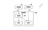
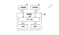
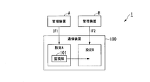
- FIG. 1 is a diagram showing a configuration of a first pattern of the communication system 1 in the present invention.
- the communication system 1 shown in FIG. 1 includes a communication device 100 and a plurality of management devices A and B.
- FIG. 1 shows a configuration in which the communication system 1 includes two management devices A and B, the number of management devices may be three or more.
- the number of management devices is the same in the description of each pattern (first pattern to eleventh pattern) shown thereafter including the first pattern. Even if the management devices A and B are single, the same applies when a plurality of IFs are set without cooperation.
- the communication device 100 includes a plurality of IFs for setting input / output (IF1 and IF2 in FIG. 1).
- the number of IFs for setting input / output is not limited to two, and may be three or more.
- the communication device 100 receives setting inputs from the management devices A and B via IFs for each setting input / output.
- IF1 is an interface for accepting input of settings from the management device A.
- IF2 is an interface for receiving input of settings from the management device B.
- setting A is a setting related to IF1
- setting B is a setting related to IF2.
- the management devices A and B make settings for the communication device 100.
- the management device A sets (for example, setting A) the communication device 100 via IF1.
- the management device B sets (for example, setting B) to the communication device 100 via IF2.
- the communication device 100 includes a monitoring unit 101.
- the monitoring unit 101 monitors the content of the setting input via IF1 (for example, the content of the setting related to the setting A).
- the monitoring unit 101 is a setting of the main setting target IF (hereinafter referred to as “setting target IF”) based on the input setting content, and if there is a setting related to another IF, the corresponding setting is set. Do it for other IFs as well.
- the monitoring unit 101 if the content of the setting input via IF1 includes a setting related to IF2, the monitoring unit 101 also performs the corresponding setting for IF2.
- IF1 is the setting target IF and IF2 is another IF.
- the monitoring unit 101 When the monitoring unit 101 needs information that is not included in the setting of the setting target IF in the setting of the other IF, the monitoring unit 101 acquires the information necessary for the setting of the other IF from the management device and uses another IF. Set the IF. For example, the monitoring unit 101 acquires information necessary for setting IF2 from the management device B, which is not included in the setting contents of setting A, and sets IF2. In this way, the monitoring unit 101 sets the setting B related to IF2. Therefore, the monitoring unit 101 includes at least an interface that reflects the contents of the setting in IF2. A default set value may be held inside and outside the monitoring unit 101 and the communication device 100, and the value may be used. The method using the default setting value is particularly suitable when the management device B does not have the information necessary for the setting.
- the monitoring unit 101 is at least an interface for acquiring information not included in the setting of the setting target IF from the setting B itself.
- setting B is a setting that summarizes the items of B-1, B-2, and B-3, and there is a change from management device A to B-2, and only the current setting value B-2 is used.
- B-1 and B-3 are acquired from setting B, and setting B is set using B-2 included in the setting contents transmitted from the management device A.
- this interface includes the default setting values of B-1 and B-3 and the setting contents transmitted from the management device A.
- Setting B is set using 2. These processes include a configuration in which the monitoring unit 101 is arranged inside the communication device 100 (FIGS. 1 to 3) and a configuration in which the monitoring unit 101 is arranged inside the software operating on the communication device 100 (FIG. 11). The same applies to.
- the monitoring unit 101 accesses the default value held inside the communication device 100 or outside the communication device 100 instead of acquiring information not included in the setting of the setting target IF from the setting B itself or the management device B. And may be configured to get the default value. Further, when the default value is held in advance by the monitoring unit 101, it is not necessary to have an interface for acquiring the default value from outside the monitoring unit 101. This process is performed in a configuration in which the monitoring unit 101 is arranged inside the communication device 100 (FIGS. 1 to 3) and a configuration in which the monitoring unit 101 is arranged inside the software operating on the communication device 100 (FIG. 11). Is the same.
- the setting history from the management device A to the setting B the setting history from the management device B to the setting B, the response history from the setting B to the management device A, or the response from the setting B to the management device B.
- the monitoring unit 101 may use the held value. In this case, the consistency with the past settings is better than when the default value is used, but the settings in the setting A cannot be reflected in the setting B until the settings in the setting B are made.
- the setting of the setting B may be changed according to the setting in the setting A at the time of setting to the setting B or after.
- the setting history from the management device A to the setting B the setting history from the management device B to the setting B, the response history from the setting B to the management device A, or the response history from the setting B to the management device B.
- the latest set value or the latest value on the priority side may be used. This process is performed in a configuration in which the monitoring unit 101 is arranged inside the communication device 100 (FIGS. 1 to 3) and a configuration in which the monitoring unit 101 is arranged inside the software operating on the communication device 100 (FIG. 11). Is the same.
- the monitoring unit 101 shows a configuration in which the content of the setting input via IF1 is monitored, but the monitoring unit 101 may monitor the content of the response output via IF1. It is particularly suitable when the actually set value is answered back. This also applies to the configuration for monitoring the contents of subsequent settings.
- the monitoring unit 101 shows a configuration for monitoring the contents of the settings input via IF1 (for example, the contents of the settings related to the setting A), but the monitoring unit 101 shows the settings input via IF2. (For example, the content of the setting related to the setting B) may be monitored.
- the monitoring unit 101 also performs the corresponding setting for IF1.
- the response to the management device A may be performed by the monitoring unit 101 or the setting A.
- setting A When setting A is performed, it may be performed without going through the monitoring unit 101, or may be performed via the monitoring unit 101.
- the monitoring unit 101 When the monitoring unit 101 performs, it is desirable that the monitoring unit 101 monitors the response from the setting A to confirm whether the response is appropriate or not, and whether or not there is an abnormal response.
- the monitoring unit 101 responds or monitors the response, it is desirable to acquire the difference between the setting content from the management device A and the setting content in the actual setting A and reflect it in the setting content in the setting B by the response. ..
- the monitoring unit 101 is arranged inside other applications, lower layers, and intermediate layers in the communication device 100 in which the setting contents are set.
- the intermediate layer is a layer having a superstructure and a substructure in a multi-layer structure.
- OS Operating System
- application software the hardware is the platform of the OS
- the OS is the platform of the application software
- the OS is also the intermediate layer. If a new platform is created between the OS and application software, it will also be an intermediate layer.
- a platform is a lower structure (base) that defines a higher structure such as hardware or software that is the basis of a computer system, and is used in an abstract state of an interface for the upper structure to use, for example, a lower layer. It is equipped with API and ABI for.
- the monitoring unit 101 itself or the layer including the monitoring unit 101 may be newly formed by hierarchical intervention in the form of bridging the existing upper layer and the layer. During hierarchical intervention, continue to secure interfaces for upper or lower layers.
- An intervention layer such as JVM (Java Virtual Machine) is placed between the OS and the application, such as JAVA (registered trademark) of a computer system, and operates on an intervention layer such as JVM such as Java applet / JAVA application.
- JVM Java Virtual Machine
- Other interfaces such as the interface to the OS, can be left almost unchanged, or the system call to the hardware made in the kernel of the OS can be modified to call the call specific to the intervention layer in order to reduce the overhead. You may use the function of.
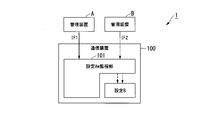
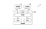
- FIG. 2 is a diagram showing a configuration of a second pattern of the communication system 1 in the present invention.
- the monitoring unit 101 included in the communication device 100 has the contents of the settings input via IF1 (for example, the contents of the settings related to the setting A) and the contents of the settings input via IF2 (for example, the settings). Monitor both of the settings related to B).
- the monitoring unit 101 In the second pattern, if the content of the setting input via IF1 includes a setting related to IF2, the monitoring unit 101 also performs the corresponding setting for IF2. Further, in the second pattern, if the content of the setting input via IF2 includes a setting related to IF1, the monitoring unit 101 also sets the corresponding setting for IF1.
- the monitoring unit 101 sets the contents of the settings related to the setting A input via the IF1 to the IF1. Further, in the second pattern, the monitoring unit 101 sets the contents of the settings related to the setting B input via the IF2 to the IF2.
- the monitoring unit 101 processes it in the same manner as the first pattern. For example, the information necessary for setting another IF is acquired from the management device and the other IF is set. For example, the monitoring unit 101 acquires information necessary for setting IF2 from the management device B, which is not included in the setting contents of setting A, and sets IF2. For example, the monitoring unit 101 acquires information about the setting A from the management device A and sets the IF1. In this way, the monitoring unit 101 sets the setting A related to IF1 and the setting B related to IF2. Therefore, the monitoring unit 101 includes at least IF1 and IF2 with an interface that reflects the contents of the setting. A default set value may be held inside and outside the monitoring unit 101 and the communication device 100, and the value may be used. The method using the default setting value is particularly suitable when the management device B does not have the information necessary for the setting.
- FIG. 3 is a diagram showing a configuration of a third pattern of the communication system 1 in the present invention.
- the monitoring unit 101 is incorporated in some of the settings, and the monitoring unit 101 included in the communication device 100 sets the contents of the settings (for example, the contents of the settings related to the setting A) and the IF2 input via IF1. Monitor both the contents of the settings input via (for example, the contents of the settings related to the setting B).
- the monitoring unit 101 if the content of the setting input via IF1 includes a setting related to IF2, the monitoring unit 101 also performs the corresponding setting for IF2. Further, in the third pattern, if the content of the setting input via IF2 includes a setting related to IF1, the monitoring unit 101 also sets the corresponding setting for IF1.
- the monitoring unit 101 processes it in the same manner as the first pattern. For example, the information necessary for setting another IF is acquired from the management device and the other IF is set. For example, the monitoring unit 101 acquires information necessary for setting IF2 from the management device B, which is not included in the setting contents of setting A, and sets IF2. For example, the monitoring unit 101 acquires information about the setting A from the management device A and sets the IF1. In this way, the monitoring unit 101 sets the setting A related to IF1 and the setting B related to IF2. Therefore, the monitoring unit 101 includes at least IF1 and IF2 with an interface that reflects the contents of the setting. A default set value may be held inside and outside the monitoring unit 101 and the communication device 100, and the value may be used. The method using the default setting value is particularly suitable when the management device B does not have the information necessary for the setting.
- the monitoring unit 101 sets the contents of the settings related to the setting A input via the IF1 to the IF1. Further, in the third pattern, the monitoring unit 101 sets the contents of the settings related to the setting B input via the IF2 to the IF2.
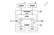
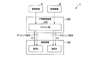
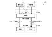
- FIG. 4 is a diagram showing a configuration of a fourth pattern of the communication system 1 in the present invention.
- the communication system 1 includes a monitoring unit 201 in the intermediate management device 200, and the monitoring unit 201 monitors the contents of the settings for some IFs (for example, the contents of the settings related to the setting A).
- the intermediate management device 200 is provided between the communication device 100 and the management devices A and B, and manages the communication device 100.
- the intermediate management device 200 includes a monitoring unit 201.
- the process performed by the monitoring unit 201 is the same as that of the monitoring unit 101 in the first pattern. That is, in the fourth pattern, the monitoring unit 201 monitors the content of the setting input via IF1 (for example, the content of the setting related to the setting A). If there is a setting related to another IF in the setting of the setting target IF, the monitoring unit 201 also sets the corresponding setting for the other IF.
- the monitoring unit 201 also performs the corresponding setting for IF2 of the communication device 100.
- IF1 is the setting target IF and IF2 is another IF.
- the monitoring unit 201 processes it in the same manner as the first pattern. For example, the information necessary for setting another IF is acquired from the management device and the other IF is set. For example, the monitoring unit 201 acquires information necessary for setting IF2 from the management device B, which is not included in the setting contents of setting A, and sets IF2 of the communication device 100. Do. In this way, the monitoring unit 201 sets the setting B related to IF2. Therefore, the monitoring unit 201 includes at least an interface that reflects the contents of the setting in IF2.
- the default set values may be held inside and outside the monitoring unit 201, the communication device 100, and the central management device 200, and the values may be used. The method using the default setting value is particularly suitable when the management device B does not have the information necessary for the setting.
- the monitoring unit 201 when acquiring information that is not included in the setting of the setting target IF from the setting B itself, the monitoring unit 201 at least an interface for acquiring information that is not included in the setting of the setting target IF from the setting B itself.
- setting B is a setting that summarizes the items of B-1, B-2, and B-3, and there is a change from management device A to B-2, and only the current setting value B-2 is used.
- B-1 and B-3 are acquired from setting B, and setting B is set using B-2 included in the setting contents transmitted from the management device A.
- this interface includes the default setting values of B-1 and B-3 and the setting contents transmitted from the management device A.
- Setting B is set using 2. This process is the same in the configuration (FIGS. 4 and 5) in which the monitoring unit 201 is arranged inside the intermediate management device 200.
- the monitoring unit 201 instead of acquiring information not included in the setting of the setting target IF from the setting B itself or the management device B, the monitoring unit 201 has a default value held inside the intermediate management device 200 or outside the intermediate management device 200. May be configured to access and get the default value. Further, when the default value is held in advance by the monitoring unit 201, there may be no interface for acquiring the default value from outside the monitoring unit 201. This process is the same in the configuration (FIGS. 4 and 5) in which the monitoring unit 201 is arranged inside the intermediate management device 200.
- the monitoring unit 201 may use the held value. Good. In this case, the consistency with the past settings is better than when the default value is used. Until the setting in setting B is made, the setting in setting A cannot be reflected in setting B. When giving priority to the setting in the setting A, the setting of the setting B may be changed according to the setting in the setting A at the time of setting to the setting B or after. In the communication system 1, when the setting history of both the setting history from the management device A to the setting B and the setting history from the management device B to the setting B is retained, the latest value set by both or the priority side of both The latest value may be used. This process is the same in the configuration (FIGS. 4 and 5) in which the monitoring unit 201 is arranged inside the intermediate management device 200.
- the response to the management device A may be performed by the monitoring unit 201 or the setting A.
- setting A When setting A is performed, it may be performed without going through the monitoring unit 201, or may be performed via the monitoring unit 201.
- the monitoring unit 201 When the monitoring unit 201 performs, it is desirable that the monitoring unit 201 monitors the response from the setting A and confirms whether the response is appropriate or not, and whether or not there is an abnormal response.
- the monitoring unit 201 responds or monitors the response, it is desirable to acquire the difference between the setting content from the management device A and the setting content in the actual setting A and reflect it in the setting content in the setting B by the response. ..
- the monitoring unit 201 shows a configuration for monitoring the contents of the settings input via IF1 (for example, the contents of the settings related to the setting A), but the monitoring unit 201 shows the settings input via IF2. (For example, the content of the setting related to the setting B) may be monitored. In this case, if the content of the setting input via IF2 includes a setting related to IF1, the monitoring unit 101 also sets the corresponding setting for IF1.
- FIG. 5 is a diagram showing a configuration of a fifth pattern of the communication system 1 in the present invention.
- the communication system 1 includes the monitoring unit 201 in the intermediate management device 200, and the monitoring unit 201 uses the setting contents (for example, the setting contents related to the setting A) input via the IF1 and the IF2. Monitor both the contents of the settings entered in the above (for example, the contents of the settings related to the setting B).
- the monitoring unit 201 if the content of the setting input via IF1 includes a setting related to IF2, the monitoring unit 201 also performs the corresponding setting for IF2. Further, in the fifth pattern, if the content of the setting input via IF2 includes a setting related to IF1, the monitoring unit 201 also performs the corresponding setting for IF1.
- the monitoring unit 201 sets the contents of the settings related to the setting A input via the IF1 to the IF1. Further, in the fifth pattern, the monitoring unit 201 sets the contents of the settings related to the setting B input via the IF2 to the IF2.
- the monitoring unit 201 processes it in the same manner as the first pattern. For example, the information necessary for setting another IF is acquired from the management device and the other IF is set. For example, the monitoring unit 201 acquires information necessary for setting IF2 from the management device B, which is not included in the setting contents of setting A, and sets IF2 of the communication device 100. Do. For example, the monitoring unit 201 acquires information necessary for setting IF1 from the management device A, which is not included in the setting contents of setting B, and sets the IF1 of the communication device 100. Do. In this way, the monitoring unit 201 sets the setting A related to IF1 and the setting B related to IF2.
- the monitoring unit 201 includes at least IF1 and IF2 with an interface that reflects the contents of the setting.
- the default set values may be held inside and outside the monitoring unit 201, the communication device 100, and the intermediate management device 200, and the values may be used.
- the method using the default setting value is particularly suitable when the management device B does not have the information necessary for the setting.
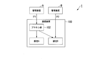
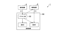
- FIG. 6 is a diagram showing a configuration of a sixth pattern of the communication system 1 in the present invention.
- the proxy unit 102 included in the communication device 100 intervenes in the setting target IF and there is a setting related to another IF in the setting of the setting target IF, the corresponding setting is set to the other IF. Also set.
- the proxy unit 102 processes the other IF settings in the same manner as in the first pattern when information that is not included in the setting target IF settings is required. For example, the information necessary for setting another IF is acquired from the management device and the other IF is set. For example, the proxy unit 102 acquires information necessary for setting IF2 from the management device B, which is not included in the setting contents of setting A, and sets IF2. In this way, the proxy unit 102 sets the setting B related to IF2. Therefore, the proxy unit 102 includes at least an interface that reflects the contents of the setting in IF2.
- the default set values may be held inside and outside the proxy unit 102 and the communication device 100, and the values may be used. The method using the default setting value is particularly suitable when the management device B does not have the information necessary for the setting.
- the proxy unit 102 is at least an interface for acquiring information not included in the setting of the setting target IF from the setting B itself.
- setting B is a setting that summarizes the items of B-1, B-2, and B-3, and there is a change from management device A to B-2, and only the current setting value B-2 is used.
- B-1 and B-3 are acquired from setting B, and setting B is set using B-2 included in the setting contents transmitted from the management device A.
- this interface includes the default setting values of B-1 and B-3 and the setting contents transmitted from the management device A.
- Setting B is set using 2. This process is the same in the configuration (FIGS. 6 to 8) in which the proxy unit 102 is arranged inside the communication device 100.
- the proxy unit 102 accesses the default value held inside the communication device 100 or outside the communication device 100 instead of acquiring information not included in the setting of the setting target IF from the setting B itself or the management device B. And may be configured to get the default value. Further, when the default value is held in advance by the proxy unit 102, there may be no interface for acquiring the default value from outside the proxy unit 102. This process is the same in the configuration (FIGS. 6 to 8) in which the proxy unit 102 is arranged inside the communication device 100.
- the proxy unit 102 may use the held value. Good. In this case, the consistency with the past settings is better than when the default value is used. Until the setting in setting B is made, the setting in setting A cannot be reflected in setting B. When giving priority to the setting in the setting A, the setting of the setting B may be changed according to the setting in the setting A at the time of setting to the setting B or after. In the communication system 1, when the setting history of both the setting history from the management device A to the setting B and the setting history from the management device B to the setting B is retained, the latest value set by both or the priority side of both The latest value may be used. This process is the same in the configuration (FIGS. 6 to 8) in which the proxy unit 102 is arranged inside the communication device 100.
- the proxy unit 102 is configured to intervene in IF1 in the sixth pattern, the proxy unit 102 may be configured to intervene in IF2. In this case, if the content of the setting input via IF2 includes a setting related to IF1, the proxy unit 102 also sets the corresponding setting for IF1.
- the proxy unit 102 may perform the response to the management device A, or the setting A may perform the response.
- the setting A When the setting A is performed, it may be performed without going through the proxy unit 102, or may be performed via the proxy unit 102.
- the proxy unit 102 When the proxy unit 102 performs, it is desirable that the proxy unit 102 monitors the response from the setting A to confirm whether the response is valid or not, and whether or not there is an abnormal response.
- the proxy unit 102 responds or monitors the response, it is desirable to acquire the difference between the setting content from the management device A and the setting content in the actual setting A and reflect it in the setting content in the setting B by the response. ..
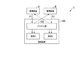
- FIG. 7 is a diagram showing a configuration of a seventh pattern of the communication system 1 in the present invention.
- the proxy unit 102 included in the communication device 100 intervenes in both IF1 and IF2, and the content of the setting input via IF1 (for example, the content of the setting related to setting A) and via IF2. Both the contents of the input settings (for example, the contents of the settings related to the setting B) are set.
- the proxy unit 102 also performs the corresponding setting for IF2 when there is a setting related to IF2 in the content of the setting input via IF1. Further, in the seventh pattern, if the content of the setting input via IF2 includes a setting related to IF1, the proxy unit 102 also sets the corresponding setting for IF1.
- the proxy unit 102 sets the contents of the settings related to the setting A input via the IF1 to the IF1. Further, in the second pattern, the proxy unit 102 sets the contents of the settings related to the setting B input via the IF2 to the IF2.
- the proxy unit 102 processes the other IF settings in the same manner as in the first pattern when information that is not included in the setting target IF settings is required.
- the information necessary for setting another IF is acquired from the management device and the other IF is set.
- the proxy unit 102 acquires information necessary for setting IF2 from the management device B, which is not included in the setting contents of setting A, and sets IF2.
- the proxy unit 102 acquires information about the setting A from the management device A and sets the IF1.
- the proxy unit 102 sets the setting A related to IF1 and the setting B related to IF2. Therefore, the proxy unit 102 includes at least IF1 and IF2 with an interface that reflects the contents of the settings.
- the default set values may be held inside and outside the proxy unit 102 and the communication device 100, and the values may be used.
- the method using the default setting value is particularly suitable when the management device B does not have the information necessary for the setting.
- FIG. 8 is a diagram showing a configuration of an eighth pattern of the communication system 1 in the present invention.
- the proxy unit 102 is incorporated in a part of the settings, and the proxy unit 102 included in the communication device 100 intervenes in both IF1 and IF2, and the content of the setting input via IF1 (for example, Both the content of the setting related to the setting A) and the content of the setting input via IF2 (for example, the content of the setting related to the setting B) are set.
- the proxy unit 102 if the content of the setting input via IF1 includes a setting related to IF2, the proxy unit 102 also performs the corresponding setting for IF2.
- the proxy unit 102 also sets the corresponding setting for IF1.
- the proxy unit 102 processes the other IF settings in the same manner as in the first pattern when information that is not included in the setting target IF settings is required.
- the information necessary for setting another IF is acquired from the management device and the other IF is set.
- the proxy unit 102 acquires information necessary for setting IF2 from the management device B, which is not included in the setting contents of setting A, and sets IF2.
- the proxy unit 102 acquires information about the setting A from the management device A and sets the IF1.
- the proxy unit 102 sets the setting A related to IF1 and the setting B related to IF2. Therefore, the proxy unit 102 includes at least IF1 and IF2 with an interface that reflects the contents of the settings.
- the default set values may be held inside and outside the proxy unit 102 and the communication device 100, and the values may be used.
- the method using the default setting value is particularly suitable when the management device B does not have the information necessary for the setting.
- the proxy unit 102 sets the contents of the settings related to the setting A input via the IF1 to the IF1. Further, in the eighth pattern, the proxy unit 102 sets the contents of the settings related to the setting B input via the IF2 to the IF2.
- FIG. 9 is a diagram showing a configuration of a ninth pattern of the communication system 1 in the present invention.
- the communication system 1 includes the proxy unit 202 in the intermediate management device 200, and the proxy unit 202 intervenes in some IFs and sets the contents of the settings for some IFs (for example, the settings related to the setting A). (Contents of) is set.
- the intermediate management device 200 includes a proxy unit 202.
- the process performed by the proxy unit 202 is the same as that of the proxy unit 102 in the sixth pattern. That is, in the ninth pattern, the proxy unit 202 intervenes in IF1 and sets the content of the setting for IF1 (for example, the content of the setting related to the setting A) in IF1. If there is a setting related to another IF in the setting of the setting target IF, the proxy unit 202 also performs the corresponding setting for the other IF. In the ninth pattern, if the content of the setting input via IF1 includes a setting related to IF2, the proxy unit 202 also performs the corresponding setting for IF2 of the communication device 100.
- the proxy unit 202 processes the other IF settings in the same manner as the first pattern when information that is not included in the setting target IF settings is required. For example, the information necessary for setting another IF is acquired from the management device and the other IF is set. For example, the proxy unit 202 acquires the information necessary for setting IF2 from the management device B, which is not included in the setting contents of setting A, and sets the IF2 of the communication device 100. Do. In this way, the proxy unit 202 sets the setting B related to IF2. Therefore, the proxy unit 202 includes at least an interface that reflects the contents of the setting in IF2. A default setting value may be held inside and outside the proxy unit 202, the communication device 100, and the central management device 200, and the value may be used. The method using the default setting value is particularly suitable when the management device B does not have the information necessary for the setting.
- the proxy unit 202 is at least an interface for acquiring information not included in the setting of the setting target IF from the setting B itself.
- setting B is a setting that summarizes the items of B-1, B-2, and B-3, there is a change from management device A to B-2, and only the current setting value B-2 is used.
- B-1 and B-3 are acquired from the setting B, and the setting B is set by using B-2 included in the setting contents transmitted from the management device A.
- this interface includes the default setting values of B-1 and B-3 and the setting contents transmitted from the management device A.
- Setting B is set using 2. This process is the same in the configuration (FIGS. 9 and 10) in which the proxy unit 202 is arranged inside the intermediate management device 200.
- the proxy unit 202 instead of acquiring information not included in the setting of the setting target IF from the setting B itself or the management device B, the default value held inside the intermediate management device 200 or outside the intermediate management device 200. May be configured to access and get the default value. Further, when the default value is held in the proxy unit 202 in advance, it is not necessary to have an interface for acquiring the default value from outside the proxy unit 202. This process is the same in the configuration (FIGS. 9 and 10) in which the proxy unit 202 is arranged inside the intermediate management device 200.
- the proxy unit 202 may use the held value. Good. In this case, the consistency with the past settings is better than when the default value is used. Until the setting in setting B is made, the setting in setting A cannot be reflected in setting B. When giving priority to the setting in the setting A, the setting of the setting B may be changed according to the setting in the setting A at the time of setting to the setting B or after. In the communication system 1, when the setting history of both the setting history from the management device A to the setting B and the setting history from the management device B to the setting B is retained, the latest value set by both or the priority side of both The latest value may be used. This process is the same in the configuration (FIGS. 9 and 10) in which the proxy unit 202 is arranged inside the intermediate management device 200.
- the proxy unit 202 may perform the response to the management device A, or the setting A may perform the response.
- setting A it may be performed without going through the proxy unit 202, or it may be performed via the proxy unit 202.
- the proxy unit 202 performs, it is desirable that the proxy unit 202 monitors the response from the setting A to confirm whether the response is valid or not, and whether or not there is an abnormal response.
- the proxy unit 202 responds or monitors the response, it is desirable to acquire the difference between the setting content from the management device A and the setting content in the actual setting A and reflect it in the setting content in the setting B by the response. ..
- the proxy unit 202 intervenes in IF1 to set the contents of the settings for IF1 (for example, the contents of the settings related to setting A), but the proxy unit 202 intervenes in IF2 and sets IF2. (For example, the content of the setting related to the setting B) may be set. In this case, if there is a setting related to IF1 via IF2, the proxy unit 202 also sets the corresponding setting for IF1.
- FIG. 10 is a diagram showing a configuration of a tenth pattern of the communication system 1 in the present invention.
- the communication system 1 includes a proxy unit 202 in the intermediate management device 200, and the proxy unit 202 intervenes in IF1 and IF2 to set contents for IF1 and IF2 (for example, regarding setting A and setting B). Set both of the settings).
- the proxy unit 202 also performs the corresponding setting for IF2 when there is a setting related to IF2 in the content of the setting for IF1. Further, in the tenth pattern, if the content of the setting for IF2 includes a setting related to IF1, the proxy unit 202 also sets the corresponding setting for IF1.
- the proxy unit 202 sets the contents of the setting related to the setting A for IF1 for IF1. Further, in the tenth pattern, the proxy unit 202 sets the contents of the setting related to the setting B for IF2 for IF2.
- the proxy unit 202 processes the other IF settings in the same manner as the first pattern when information that is not included in the setting target IF settings is required. For example, the information necessary for setting another IF is acquired from the management device and the other IF is set. For example, the proxy unit 202 acquires the information necessary for setting IF2 from the management device B, which is not included in the setting contents of setting A, and sets the IF2 of the communication device 100. Do. For example, the proxy unit 202 acquires the information necessary for the setting of IF1 from the management device A, which is not included in the setting contents of setting B, and sets the IF1 of the communication device 100. Do. In this way, the proxy unit 202 sets the setting A related to IF1 and the setting B related to IF2.
- the proxy unit 202 includes at least IF1 and IF2 with an interface that reflects the contents of the settings.
- a default setting value may be held inside and outside the proxy unit 202, the communication device 100, and the intermediate management device 200, and the value may be used.
- the method using the default setting value is particularly suitable when the management device B does not have the information necessary for the setting.
- FIG. 11 is a diagram showing the configuration of the eleventh pattern of the communication system 1 in the present invention.
- the monitoring unit 101 is included in the setting application that operates on the communication device 100.
- the monitoring unit 101 monitors the contents of the settings input via IF1 (for example, the contents of the settings related to the setting A). If there is a setting related to another IF in the setting of the setting target IF, the monitoring unit 101 also sets the corresponding setting for the other IF.
- the content of the setting input via IF1 includes a setting related to IF2
- the monitoring unit 101 also performs the corresponding setting for IF2.
- the monitoring unit 101 processes it in the same manner as the first pattern. For example, the information necessary for setting another IF is acquired from the management device and the other IF is set. For example, the monitoring unit 101 acquires information necessary for setting IF2 from the management device B, which is not included in the setting contents of setting A, and sets IF2. In this way, the monitoring unit 101 sets the setting A related to IF1. Therefore, the monitoring unit 101 includes at least an interface that reflects the contents of the setting in IF2. A default set value may be held inside and outside the monitoring unit 101 and the communication device 100, and the value may be used. The method using the default setting value is particularly suitable when the management device B does not have the information necessary for the setting.
- the monitoring unit 101 shows a configuration for monitoring the contents of the settings input via IF1 (for example, the contents of the settings related to the setting A), but the monitoring unit 101 shows the settings input via IF2. (For example, the content of the setting related to the setting B) may be monitored. In this case, if the content of the setting input via IF2 includes a setting related to IF1, the monitoring unit 101 also sets the corresponding setting for IF1.
- the configurations of the first pattern to the eleventh pattern are suitable when they can be set as other IFs and can be set from a plurality of systems for a single IF.
- the single IF can be set only from a single system
- the second pattern, the third pattern, the fifth pattern, the seventh pattern, the eighth pattern, and the tenth pattern are suitable.
- the 6th to 10th patterns are suitable. This is because when the setting source is authenticated, the monitoring units 101 and 201 have a plurality of setting sources, which may result in inconsistency. On the other hand, in the case of the proxy unit 102 and the proxy unit 202, since they are a single setting source, inconsistencies are unlikely to occur.
- FIGS. 1 to 11 a case where settings corresponding to other IFs are performed based on the contents of settings input via a certain IF has been described as an example, but conversely, settings input via other IFs have been described. The same applies to the case where the setting corresponding to a certain IF is made based on the content. Further, it may be bidirectional from one IF to another and from another IF to a certain IF instead of one direction. Further, in FIGS. 1 to 11, the outputs from the management devices A and B are input to the monitoring units 101 and 201 (setting unit) / proxy units 102 and 202 (setting unit), and the monitoring units 101 and 201 (setting unit).
- the monitoring units 101 and 201 (setting units) / proxy units 102 and 202 (setting units) may be devices such as the communication device 100, the intermediate management device 200, and the relay device (not shown), or the setting A / It may be lower layer software or firmware such as Operation System that provides a platform on which settings B and functions that operate according to the settings operate, or setting A / setting B and functions that operate according to the settings operate. It may be a function on the platform, for example, a function of communicating with management devices A, B, etc., or a function of a switch or the like that mediates communication between functions inside the device. In the former case of the monitoring units 101 and 201 (setting unit), there is an effect that the intervention of the monitoring units 101 and 201 (setting unit) can be easily concealed especially when the response is returned to the management devices A and B.
- the output from the management devices A and B can be output from the monitoring units 101 and 201 (setting unit).
- the output from the management devices A and B is duplicated and output to both the monitoring units 101 and 201 (setting unit) / proxy units 102 and 202 (setting unit) and the setting, from the management device to the setting.
- the response from the setting to the management devices A and B is terminated, and the response from the proxy units 102 and 202 (setting unit) is input to the management devices A and B.
- Intervention, agency, duplication, and snuffing may be performed by the communication device 100 or the intermediate management device 200 itself, or a lower level such as Operation System that provides a platform on which the setting A / setting B and the functions operating according to the settings operate. It may be performed by layer software or firmware, or between settings A / B and functions on the platform on which the functions that operate according to the settings operate, such as communication functions with management devices A and B and functions inside the device. It may be performed by a function such as a switch that mediates communication.
- FIG. 12 is a diagram showing a configuration for transmitting to the management device that the setting change has been made in the first pattern of the communication system 1 in the present invention.
- the configuration of the communication system 1 shown in FIG. 12 is the same as the configuration of the system shown in FIG. In the first pattern, when the monitoring unit 101 monitors the contents of the settings input via IF1 (for example, the contents of the settings related to the setting A), the monitoring unit 101 sets the IF2 and then changes the settings. It is transmitted to the management device B.
- the monitoring unit 101 sets the IF1 and then sets the setting.
- the change is transmitted to the management device A.
- the response to the setting A is not described in the management device A in FIG. 12, it is desirable to respond. This also applies to the subsequent patterns.
- FIG. 13 is a diagram showing a configuration for transmitting to the management device that the setting change has been made in the second pattern of the communication system 1 in the present invention.
- the configuration of the communication system 1 shown in FIG. 13 is the same as the configuration of the system shown in FIG.
- the monitoring unit 101 changes the setting of IF2 based on the content of the setting input via IF1 in the second pattern
- the monitoring unit 101 transmits the setting change to the management device B after making the setting for IF2. .
- the monitoring unit 101 changes the setting of IF1 based on the content of the setting input via IF2 in the second pattern
- the monitoring unit 101 transmits the setting change to the management device A after making the setting for IF1. ..
- FIG. 14 is a diagram showing a configuration for transmitting to the management device that the setting change has been made in the third pattern of the communication system 1 in the present invention.
- the configuration of the communication system 1 shown in FIG. 14 is the same as the configuration of the system shown in FIG.
- the monitoring unit 101 changes the setting of IF2 based on the content of the setting input via IF1 in the third pattern
- the monitoring unit 101 transmits the setting change to the management device B after making the setting for IF2. .
- the monitoring unit 101 changes the setting of IF1 based on the content of the setting input via IF2 in the third pattern
- the monitoring unit 101 transmits the setting change to the management device A after making the setting for IF1. ..
- FIG. 15 is a diagram showing a configuration for transmitting to the management device that the setting change has been made in the fourth pattern of the communication system 1 in the present invention.
- the configuration of the communication system 1 shown in FIG. 15 is the same as the configuration of the system shown in FIG.
- the monitoring unit 201 changes the setting of IF2 in relation to the content of the setting for IF1 in the fourth pattern
- the monitoring unit 201 transmits the setting change to the management device B after making the setting for IF2.
- the monitoring unit 201 changes the setting of IF1 in relation to the content of the setting for IF2 in the third pattern
- the monitoring unit 201 transmits the setting change to the management device A after making the setting for IF1.
- FIG. 16 is a diagram showing a configuration for transmitting to the management device that the setting change has been made in the fifth pattern of the communication system 1 in the present invention.
- the configuration of the communication system 1 shown in FIG. 16 is the same as the configuration of the system shown in FIG.
- the monitoring unit 201 changes the setting of IF2 in relation to the content of the setting for IF1 in the fifth pattern
- the monitoring unit 201 transmits the setting change to the management device B after making the setting for IF2.
- the monitoring unit 201 changes the setting of IF1 in relation to the content of the setting for IF2 in the fifth pattern
- the monitoring unit 201 transmits the setting change to the management device A after making the setting for IF1.
- FIG. 17 is a diagram showing a configuration for transmitting to the management device that the setting change has been made in the sixth pattern of the communication system 1 in the present invention.
- the configuration of the communication system 1 shown in FIG. 17 is the same as the configuration of the system shown in FIG.
- the proxy unit 102 changes the setting of IF2 based on the content of the setting input via IF1 in the sixth pattern
- the proxy unit 102 transmits the setting change to the management device B after making the setting for IF2. .
- the proxy unit 102 changes the setting of IF1 based on the content of the setting input via IF2 in the sixth pattern
- the proxy unit 102 transmits the setting change to the management device A after making the setting for IF1. ..
- FIG. 18 is a diagram showing a configuration for transmitting to the management device that the setting change has been made in the seventh pattern of the communication system 1 in the present invention.
- the configuration of the communication system 1 shown in FIG. 18 is the same as the configuration of the system shown in FIG. 7.
- the monitoring unit 102 transmits the setting change to the management device B after making the setting for IF2. ..
- the proxy unit 102 changes the setting of IF1 based on the content of the setting input via IF2 in the seventh pattern
- the proxy unit 102 transmits the setting change to the management device A after making the setting for IF1. ..
- FIG. 19 is a diagram showing a configuration for transmitting to the management device that the setting change has been made in the eighth pattern of the communication system 1 in the present invention.
- the configuration of the communication system 1 shown in FIG. 19 is the same as the configuration of the system shown in FIG.
- the proxy unit 102 changes the setting of IF2 based on the content of the setting input via IF1 in the eighth pattern
- the proxy unit 102 transmits the setting change to the management device B after making the setting for IF2. .
- the proxy unit 102 changes the setting of IF1 based on the content of the setting input via IF2 in the eighth pattern
- the proxy unit 102 transmits the setting change to the management device A after making the setting for IF1. ..
- FIG. 20 is a diagram showing a configuration for transmitting to the management device that the setting change has been made in the ninth pattern of the communication system 1 in the present invention.
- the configuration of the communication system 1 shown in FIG. 20 is the same as the configuration of the system shown in FIG.
- the proxy unit 202 changes the setting of IF2 in relation to the content of the setting for IF1 in the ninth pattern
- the proxy unit 202 transmits the setting change to the management device B after making the setting for IF2.
- the proxy unit 202 changes the setting of IF1 in relation to the content of the setting for IF2 in the ninth pattern
- the proxy unit 202 transmits the setting change to the management device A after making the setting for IF1.
- FIG. 21 is a diagram showing a configuration for transmitting to the management device that the setting change has been made in the tenth pattern of the communication system 1 in the present invention.
- the configuration of the communication system 1 shown in FIG. 21 is the same as the configuration of the system shown in FIG.
- the proxy unit 202 changes the setting of IF2 in relation to the content of the setting for IF1 in the tenth pattern
- the proxy unit 202 transmits the setting change to the management device B after making the setting for IF2.
- the proxy unit 202 changes the setting of IF1 in relation to the content of the setting for IF2 in the tenth pattern
- the proxy unit 202 transmits the setting change to the management device A after making the setting for IF1.
- FIG. 22 is a diagram showing a configuration for transmitting to the management device that the setting change has been made in the eleventh pattern of the communication system 1 in the present invention.
- the configuration of the communication system 1 shown in FIG. 22 is the same as the configuration of the system shown in FIG.
- the monitoring unit 101 changes the setting of IF2 based on the content of the setting input via IF1 in the eleventh pattern
- the monitoring unit 101 transmits the setting change to the management device B after making the setting for IF2. .
- the monitoring unit 101 changes the setting of IF1 based on the content of the setting input via IF2 in the eleventh pattern
- the monitoring unit 101 transmits the setting change to the management device A after making the setting for IF1. ..
- the monitoring units 101 and 201 or the proxy units 102 and 202 are arranged as applications on FASA and ONOS to change the settings of routing tables such as IPTABLES and SPP and routers and switches such as OvSW for traffic to VOLTHA.
- DNS information may be rewritten and transferred, and may be transmitted to VOLTHA after processing.
- monitoring units 101, 201 or proxy units 102, 202 are arranged as applications on ONOS, and control traffic such as GUI, CLI, REST, etc. to VOLTHA and ONOS is sent to routing tables such as IPTABLES and SPP, OvSW, etc. You may change the settings of the router or switch, transfer it, and send it to VOLTHA after processing. In this case, since the input from both interfaces is obtained, it may be held inside or outside the application, and the contents of each held may be controlled by comparing with periodic or some event.
- An application on FASA or ONOS may hold a DB or have an access right to the DB, and control both of them by comparing them periodically or at some event.
- the monitoring unit 101, the monitoring unit 201 or the proxy unit 102, and the proxy unit 202 are input to a part of the plurality of IFs included in the communication device 100. If the settings include settings related to other interfaces, the settings are also made for the other interfaces. As a result, even when there are inputs from a plurality of IFs in a single device, it is possible to make settings related to the other IF by setting one IF. Therefore, the order of the settings is maintained, and it is possible to suppress the occurrence of inconsistency in the setting information.
- the monitoring unit 101, the monitoring unit 201 or the proxy unit 102, or the proxy unit 202 requires information not included in the setting contents in the setting of other IFs
- the monitoring unit 101, the proxy unit 201, or the proxy unit 202 processes in the same manner as the first pattern. For example, the information required for the setting is acquired from the management device and another IF is set. This makes it possible to set other IFs.
- the communication device is, for example, a communication device that executes communication with another communication device by a signal such as an optical signal via a communication network such as an optical fiber network such as ODN such as PON.
- the communication device is, for example, an OLT.
- the communication device may be, for example, an OSU (Optical Subscriber Unit).
- the communication device may be, for example, a combination of an OLT having or not having a switch unit (SW: Switch) for switching an optical signal and another SW.
- SW switch unit
- the communication device may be, for example, a combination of an OLT and an ONU.
- the communication device may include a plurality of devices.
- the communication device may be another communication device such as an ONU, a multiplexer (MUX: multiplexer), a demultiplexer (DMUX: demultiplexer), or a SW.
- the communication device may be composed of a plurality of components. Each component may be contained in a single device or in a separate device.
- the communication device may be one virtual device composed of a plurality of devices.
- the virtual device is an OLT setting management system such as an operation system (OpS: Operation System), OSS (Operation Support System), NE (Network Element) control NE-OpS, NE controller, and NE-OpS. EMS, etc. (Element Management System (OpS, OSS, NE-OpS, NE controller, EMS may be referred to as OpS, etc., or one of them may be represented on behalf of the other)). May be good.
- OLT setting management system such as an operation system (OpS: Operation System), OSS (Operation Support System),
- the communication device is an OPT recommended ITU-T recommendation such as a TWDM (Time and Wavelength Division Multiplexing) -PON system such as NG-PON2 (Next Generation-PON2). , Operation, etc. are illustrated.
- TWDM-PON is used, but PON refers to G.I.
- G.A. other than TWDM-PON conforming to the 989 series. 987, G.M. 984, G.M.
- PON is a G.M. 987, G.M. 984, G.M. It may be an XG-PON, G-PON, B (Broadband) PON conforming to the 983 series, or an IEEE standard compliant PON such as GE (Gigabit Ethernet (registered trademark)) -PON, 10 GE-PON. There may be.
- the TC (Transmission Convergence) layer and the PMD (Physical Medium Dependent) layer can be read as the corresponding layers in the standard.
- the communication device has hardware or software or a combination thereof as a component or a componentized function.
- a communication device is an application in which functions different for each service or each communication carrier are realized by using a generalized input / output interface (for example, FASA (Flexible Access System Architecture) application API).
- FASA Flexible Access System Architecture
- Access that provides software components such as (for example, FASA applications) and the input / output interface that is generalized to the software components and functions that do not need to be changed according to services or requests because they are standardized.
- It includes a basic component of a network device (for example, a FASA board).
- a general-purpose input / output interface it is easy to add or replace functions, and services of various requests can be provided flexibly and promptly.
- an application is also referred to as an "application”.
- the exchange between the parts is performed, for example, via the middleware unit 120 described later, but an original transfer path or means of the communication device 51 may be used, OpenFlow, Netconf / YANG, or SNMP (Simple Network Management Protocol). You may use standardized means such as.
- the communication between parts is the route of the internal wiring, backboard, OAM (Operation Administration and Maintenance) section, main signal line, dedicated wiring, OpS, controller or control panel (Cont: CONTrol board, CONTrol panel), etc. It can be either.
- OAM Operaation Administration and Maintenance
- main signal line dedicated wiring, OpS, controller or control panel
- CONTrol board CONTrol panel
- the communication between parts is directly terminated and input, it may be encapsulated in the OAM section or the main signal. Communication between parts may be terminated at any point and input via internal wiring, backboard, OAM section, main signal line, dedicated wiring, OpS, etc., via a path such as a controller or control panel. ..
- OAM section or main signal line it is desirable to encapsulate it in the OAM section or main signal.
- the communication device further includes an interface for software components in an application such as a FASA application or a platform such as a FASA platform.
- the communication device described in the 1-1 embodiment is used as the communication device shown in FIG.
- examples 1 to 6 will be described as examples of the architecture of the communication device.
- the architecture of the communication device constituting the communication system may be an architecture other than the first to sixth examples described below.
- the software part of the communication device in the first to sixth examples of the architecture may be a hardware part.
- FIG. 23 is a diagram showing a first example of the architecture of the communication device.
- the communication device includes a non-general-purpose device-dependent unit 110 whose operation depends on the device, and a middleware unit 120 that hides the difference between the hardware and software of the device-dependent unit 110 and the device-dependent application unit 150.
- a general-purpose device-independent application unit 130 whose operation does not depend on the device and a device-dependent application unit 150 are provided. Therefore, the device-dependent section 110 (vendor-dependent section) is a functional section that depends on the standard to which the device of the communication device conforms and the manufacturing vendor of the device. In other words, the device-dependent unit 110 has low compatibility with other communication devices, and cannot be used as it is for newly manufactured communication devices (particularly, devices having different conforming standards or manufacturing vendors).
- the device-dependent unit 110 executes one or more functions provided in the network device.
- the device-independent application unit 130 is a functional unit that does not depend on the standard, method, device type, device generation, or device manufacturing vendor to which the device of the communication device conforms.
- the device-independent application unit 130 has high compatibility with other communication devices, and can be used as it is for newly manufactured communication devices (particularly, devices having different conforming standards and manufacturing vendors).
- Specific examples of the application provided in the device-independent application unit 130 include an application that performs setting processing in a network device, an application that performs setting change processing, an application that performs algorithm processing, and the like.
- the middleware unit 120 and the device-independent application unit 130 are connected via the device-independent API 21.
- the device-independent API 21 is an input / output IF that does not depend on the device.
- the device-dependent section 110 includes, for example, a hardware section 111 (PHY), a hardware section 112 (MAC), a hardware section 111 (PHY), and a hardware section that depend on the standard of the device-dependent section 110 or the device manufacturing vendor. At least a part of the hardware unit 111 (PHY), the hardware unit 112 (MAC), and the software unit 113 of the software unit 113 and the OAM unit 114 that execute the driver and firmware that drive the 112 (MAC), and the device-dependent unit 110. It is configured to include a device-dependent application unit 150 that drives the device.
- the hardware unit 111 (PHY), the hardware unit 112 (MAC), the software unit 113, the OAM unit 114, and the middleware unit 120 are connected via the device-dependent API 23.
- the device-dependent API 23 is a device-dependent input / output IF.
- the device-dependent unit 110 further includes a NE management / control unit 115.
- the NE management / control unit 115 and the middleware unit 120 are connected via the device-dependent API 25.
- the device-dependent API 25 is an input / output IF that depends on the device.
- the middleware unit 120 and the device-dependent application unit 150 are connected by the device-dependent API 23.
- the device-dependent application unit 150, the OAM unit 114 of the device-dependent unit 110, the software unit 113, the hardware unit 111 (PHY), and the hardware unit 112 (MAC) are connected by the device-dependent API 24.
- the device-dependent application unit 150 and the management / control agent unit 133 are connected by the API 26.
- the device-dependent unit 110 or the device-independent application unit 130 is derived from the limitation derived from the processing for realizing the middleware unit 120 or the device-independent application unit 130, for example, the processing capacity of the software. In addition to the restrictions to be applied, it may be determined according to the frequency of function updates, the importance of extended functions, and the like. As a result, the communication device can facilitate the flexible and quick addition of the extended function unit (unique function unit) by the device-independent application unit 130, and can provide the communication service in a timely manner.
- DBA Dynamic Bandwidth Assignment
- the device-dependent unit 110 or device-independent You may decide to use the application unit 130.
- the device-independent application unit 130 may be used because the difference is small with respect to at least one of the standard, generation, method, system, device type, and manufacturing vendor to which the device to be shared conforms.
- a predetermined function such as DBA is arranged in the device-dependent part or the device-independent application, but depending on the function deployment, both may be the device-independent application or both may be the device-dependent part. ..
- an information processing unit such as a processor equipped with a processing unit for a function such as DBA is provided in a powerless transmitter / receiver, and the application or the like is provided in another part having a powerful information processing capability.
- a processing unit for a function such as DBA
- the application or the like is provided in another part having a powerful information processing capability.
- inter-processor communication or inter-device communication between devices works as middleware in preparation for an information processing unit, for example, OSU.
- the functions such as DBA are compiled as a part of the firmware or the like as in the previous example.
- a common IF for executing the function may be used.
- the common IF may include IFs and parameters that are not used in any of the standards, generations, methods, systems, device types, and manufacturing vendors to which the device-dependent unit 110 conforms.
- a conversion function unit that converts IFs and parameters so as to correspond to the device-dependent unit 110, and a function unit that automatically sets IFs and parameters corresponding to insufficient IFs and parameters may be further provided.
- the device-dependent unit 110 shown in FIG. 23 includes a hardware unit 111 (PHY), a hardware unit 112 (MAC), and a software unit 113.
- the hardware unit 111 (PHY) executes (PHYsical sublayer processing) from the physical layer to processing related to optical transmission / reception.
- the hardware unit 112 (MAC) executes MAC (Media Access Control) processing.
- the hardware unit 111 (PHY) and the hardware unit 112 (MAC) depend on the standards and manufacturing vendors to which they comply.
- the software unit 113 executes device-dependent drivers, firmware, applications, and the like.
- the hardware unit 111 (PHY) and the hardware unit 112 (MAC) of the device-dependent unit 110 may be provided with a general-purpose server, layer 2SW, or the like in addition to these.
- the device-dependent unit 110 does not have to include the hardware unit 112 (MAC).
- the device-dependent unit 110 does not have to include a part of the hardware unit 111 (PHY).
- the device-dependent unit 110 does not include low-level signal processing such as modulation / demodulation signal processing, forward error correction (FEC: Forward Error Correction), code decoding processing, and encryption processing, and may have only optical-related functions. Good.
- the device-dependent unit 110 does not have to include a PCS (PHYsical Coding Sublayer) that encodes data.
- PCS Physical Coding Sublayer
- the device-dependent unit 110 does not have to include a PMA (Physical Medium Attachment) for serializing data and a PCS.
- the device-dependent unit 110 does not have to include a PMD connected to a physical medium.
- the middleware unit 120 directly drives, controls, operates or manages the hardware unit 111 (PHY) and the hardware unit 112 (MAC) of the device-dependent unit 110 without going through the software unit 113, the device-dependent unit 110 may be used.
- the software unit 113 may not be provided.
- the device-independent application unit 130 includes, for example, extended function units 131-1 to 131-3 (extended function A, extended function B and extended function C in FIG. 23), a basic function unit 132, and a management / control agent unit. It is provided with 133.
- the management / control agent unit 133 exchanges data from the EMS 140.
- the EMS 140 and the external device 160 are connected to the device-independent application unit 130 via the middleware unit 120, but the EMS 140 and the external device 160 are not necessarily connected to the device-independent application unit 130 via the middleware unit 120. You don't have to.
- the EMS 140 and the external device 160 may be appropriately connected to the middleware unit 120 or may be directly connected to the device-independent application unit 130, if necessary. Further, although it is expressed as "connecting via the middleware unit 120", this expression is an expression from the viewpoint of the device-independent application unit 130. In reality, device-independent apps are connected to each other via the middleware unit 120 after the connection by hardware.
- extended function unit 131 matters common to the extended function units 131-1 to 131-3 will be referred to as "extended function unit 131" by omitting a part of the reference numerals.
- EMS140 is, for example, OpS or the like.
- the device-independent application unit 130 may not include any of the extended function unit 131, the basic function unit 132, and the management / control agent unit 133, and the management / control agent unit 133 is the basic function unit 132.
- the management / control agent unit 133 may be included in the basic function unit 132 or the middleware unit 120.
- the device-independent application unit 130 may further include a configuration other than the extended function unit 131, the basic function unit 132, and the management / control agent unit 133. For example, when the extended function unit 131 is unnecessary, the device-independent application unit 130 does not have to include the extended function unit 131. Further, the device-independent application unit 130 may include one or more extended function units 131.
- the extended function unit 131 can be added, deleted, replaced or changed independently without unnecessarily affecting other functions.
- the extension function unit 131 may be added, deleted, replaced, or changed as appropriate when, for example, a multicast service or an extension function unit 131 that executes power saving measures is required according to a service request. ..
- the basic function unit 132 may be included in the device-independent application unit 130 as a part of the extension function unit 131, or may be replaced by a function unit lower than the middleware unit 120.
- the extended function unit 131 includes the basic function unit 132
- the device-independent application unit 130 does not have to include the basic function unit 132.
- a functional unit lower than the middleware unit 120 replaces the basic function unit 132
- the device-independent application unit 130 does not have to include the basic function unit 132.
- the extended function unit 131 includes the basic function unit 132 and the function unit lower than the middleware unit 120 substitutes for the basic function unit 132, the device-independent application unit 130 does not have to include the basic function unit 132.
- the management / control agent unit 133 does not have to input / output with the EMS 140 when it automatically sets according to a predetermined setting without receiving the communication from the EMS 140. Further, when the management / control agent unit 133 does not have the management setting function and the other device-independent application unit 130, the basic function unit 132, or the device-dependent unit 110 has the management setting function, the device-independent application unit 130 The management / control agent unit 133 may not be provided.
- the device-dependent unit 110 may be replaced by the NE management / control unit 115 and the device-dependent application unit 150 (see FIG. 24 described later), which is a lower function unit of the NE management / control unit 115.
- the management / control agent unit 133 When the management / control agent unit 133 automatically sets according to a predetermined setting, it is not necessary to input / output information to / from the EMS 140. Further, when the management / control agent unit 133 does not have the management setting function and the other device-independent application unit 130, the basic function unit 132, or the device-dependent unit 110 has the management setting function, the device-independent application unit 130 manages. -The control agent unit 133 does not have to be provided. Information may be directly input / output between the EMS 140 and the device-independent application unit 130.
- the device-dependent application unit 150 may input / output information via the middleware unit 120, may directly input / output information from the management / control agent unit 133, or may input / output information directly between the two. Information may be input / output, or may be directly input / output to and from EMS140. Further, when the device-dependent application unit 150 is automatically set according to a predetermined setting without receiving communication from the EMS 140, and management and control information can be acquired from the EMS 140 via the middleware unit 120, the device The independent application unit 130 does not have to include the management / control agent unit 133.
- the device-independent application unit 130 inputs information via the middleware unit 120 at least between the hardware unit 111 (PHY) and the hardware unit 112 (MAC) of the device-dependent unit 110 or between the software unit 113. Output.
- the device-independent application unit 130 inputs / outputs to and from each other via the middleware unit 120 as needed.
- the device-independent application unit 130 executes control or management according to the information input / output to / from the EMS 140
- the device-independent application unit 130 transfers the information to / from the management / control agent unit 133 that receives communication from the EMS 140. Input / output.
- An example of input / output between the device-independent application unit 130 and the device-dependent unit 110 is as follows.
- the DBA application unit and the protection application unit input / output information to and from the embedded OAM engine of the TC layer.
- the DWBA (Dynamic Wavelength and Bandwidth Assignment) application and the ONU registration authentication application unit input / output information to and from the PLOAM engine of the TC layer.
- the power saving application unit inputs / outputs information to and from the OMCI and the L2 main signal processing function unit (L2 function (Layer 2 function) unit).
- L2 function Layer 2 function
- the MLD (Multicast Listener Discover) proxy application section inputs and outputs information to and from the L2 function section.
- the low-speed monitoring application (OMCI) inputs and outputs information to and from OMCI.
- the OMCI and L2 functional units operate the XGEM framer (XGPON Encapsulation Method Framer) and encryption.
- DWBA and DBA may be separate, integrated, or combined.
- the management / control agent unit 133 is an application unit of the maintenance operation function, and inputs / outputs information to and from EMS 140, which is an OpS for the NE management / control unit 115.
- the implementation of the device-independent application unit 130 may have a priority.
- the management / control agent unit 133 has the highest priority.
- the second priority is, for example, a DBA application, a DWBA application, a power saving application, an ONU registration authentication application, an MLD proxy application, a protection application, and a low-speed monitoring application (OMCI).
- the application of the extended function unit 131 only the application for driving the functions prepared for some vendors, methods, types, and generations and the devices of some vendors, methods, types, and generations via the device-independent API 21. It may include an app that drives the features provided for.
- the management / control agent unit 133 inputs / outputs to and from the EMS 140 and the middleware unit 120.
- the middleware unit 120 inputs / outputs NE management information and control information to / from the NE management / control unit 115.
- the NE management / control unit 115 may directly transmit / receive NE management information and control information to / from the EMS 140 without going through the middleware unit 120, or may send / receive NE management information and control information via the management / control agent unit 133. You may send and receive.
- the device-dependent application unit 150 inputs / outputs NE management information and control information to / from the management / control agent unit 133.
- the device-dependent application unit 150 may directly input / output information to / from the EMS 140 without going through the management / control agent unit 133.
- the management / control agent unit 133 inputs / outputs information between the EMS 140, the middleware unit 120, and the device-dependent application unit 150.
- the middleware unit 120 inputs / outputs NE management information and control information to / from the NE management / control unit 115.
- the middleware unit 120 inputs / outputs information via the device-independent application unit 130 and the device-independent API 21.
- the middleware unit 120 inputs / outputs information to / from the OAM unit 114 of the device-dependent unit 110, the driver, the firmware, the hardware unit 111 (PHY), or the hardware unit 112 (MAC) via the device-dependent API 23.
- the middleware unit 120 outputs the input information as it is or in a predetermined format. For example, if the output destination is each part of the device-independent application unit 130, the middleware unit 120 converts the information into the input format of each part of the device-independent API 21.
- the middleware unit 120 is the device-dependent API 23 in the form of input to each. After converting to the format, or after terminating and performing the predetermined processing, the information is transmitted to the output destination.
- the middleware unit 120 deletes unnecessary input information at each input destination, and if there is insufficient information, it can collect and supplement it via another device-independent API 21 or device-dependent API 23. desirable. Further, when inputting to the middleware unit 120, it may be broadcast or multicast to broadcast to a related application or the like.
- the middleware unit 120 and the device-dependent unit 110 are illustrated as a single unit, but each may be composed of a plurality of units.
- the middleware unit 120 may input / output across the processors and hardware by using interprocessor communication or the like.
- the device-independent application unit 130 and the device-independent application unit 130 may be arranged in the user space on a single processor as an execution program such as a DLL (Dynamic Link Library), or on a plurality of processors. It may be arranged in the user space.
- DLL Dynamic Link Library
- the device-independent application unit 130 may be arranged in the kernel space after securing input / output IFs such as API, or may be arranged together with the middleware unit 120 having an IF that can be independently replaced with firmware or the like. Alternatively, it may be incorporated into firmware or the like and recompiled.
- the user space and kernel space may be any combination for each device-independent application unit 130.
- the device-independent application unit 130 corresponding to the same function may be implemented in both the user space and the kernel space. In this case, for example, it may be switched and one of them may be selected, both may be processed in cooperation, or only one of them may be actually processed. The same applies to the software of the device-dependent unit 110.
- the more high-speed processing such as main signal processing, DBA processing, and low-layer signal processing is required, the more there is a trade-off with the immediacy of expandability / replacement, but high-speed processing with less overhead is expected. It is desirable to incorporate it in the kernel space or firmware.
- the processor on which the device-dependent application unit 150 (see FIG. 24 to be described later) is also arranged is a processor that actually processes or its processor from the viewpoint of limiting the bus and speed due to inter-processor communication and affecting other programs due to occupation of the communication path. It is desirable to place it in the user space, kernel space, or firmware of a nearby processor. However, in order to reduce the capacity of the processor to be actually processed or a processor in the vicinity thereof, the communication cost due to the inter-processor communication increases, but the processing may be performed by a remote processor.
- the device-independent API 21 is provided in the middleware unit 120 in advance assuming the extended function unit 131 to be added, but it is necessary in a form of suppressing modification of the device-dependent API 23 and other device-independent application units 130. It may be added or deleted accordingly.
- the softened area is the basic function unit 132, the management / control agent unit 133, the extended function unit 131, and the middleware unit 120, but the softened area is the service adaptation (encryption, fragment processing, GEM).
- Framed / XGEM framing, PHY adaptation FEC, scrambling, synchronous block generation / extraction, GTC (GPON Transmission Convergences) framing, PHY framing, SP conversion, and encryption method may also be targeted.
- Architecture software function An example of implementation of the above and an example of function deployment corresponding to the hardware unit will be described.
- the function deployment includes, for example, a software function in a network device or an external server. This is the same in other examples.
- the device-dependent application unit 150 is unnecessary, the device-dependent application unit 150, the API 24, and the API 26 may not be provided. This configuration is called the second example of the architecture.
- the middleware unit 120 becomes complicated because the device-dependent application unit 150 is not provided.
- FIG. 24 is a diagram showing a third example of the architecture of the communication device.
- the basic function unit 132 is the hardware unit 111 (PHY), the hardware unit 112 (MAC), and the extended function unit 131. And input / output.
- the other device-independent application unit 130 and the device-dependent application unit 150 are the same as those in the first example of the architecture.
- the EMS 140 and the external device 160 are connected to the device-independent application unit 130 via the basic function unit 132, but the EMS 140 and the external device 160 are not necessarily device-independent via the basic function unit 132. It is not necessary to connect to the application unit 130.
- the EMS 140 and the external device 160 may be appropriately connected to the middleware unit 120 or may be directly connected to the device-independent application unit 130, if necessary. Further, although it is expressed as "connecting via the middleware unit 120", this expression is an expression from the viewpoint of the device-independent application unit 130. In reality, device-independent apps are connected to each other via the middleware unit 120 after the connection by hardware.
- the third example uses the middleware unit 120 including the device-dependent APIs 23 and 25 for each device having at least one of a compliant standard, generation, method, system, device type, and manufacturing vendor. No need to create.
- the communication device of the third example of the architecture has the effect of generalizing and porting more functions between generations between devices, facilitating verification of connectivity, and making the functions of the devices robust.
- the communication device includes a device-dependent unit 110 and a device-independent application unit 130.
- the device-dependent section 110 includes a hardware section 111 (PHY) and a hardware section 112 (MAC), and a hardware section 111 (PHY) and a hardware section 112 (MAC), which depend on a compliant standard or a device manufacturing vendor. It includes a software unit 113 such as a driver and firmware for driving the device, and a device-dependent application unit 150 for driving at least a part of the device-dependent unit 110.
- the driver or the like hides the difference in the device-dependent unit 110.
- the device-independent application unit 130 is a general-purpose device-independent application that executes device-independent processing, and includes an extended function unit 131 and a basic function unit 132.
- the basic function unit 132 is via a driver that hides the difference between the hardware unit 111 (PHY) and the hardware unit 112 (MAC) and the device-dependent software unit 113, or the device-independent API 27 (porting IF) or device. It is connected to the device-dependent unit 110 via the dependent application unit 150, and data is transferred between the hardware unit 111 (PHY) and the hardware unit 112 (MAC) of the device-dependent unit 110 and the device-dependent software unit 113. Input / output.
- the basic function unit 132 and the extended function unit 131 in the device-independent application unit 130 are connected via the device-independent API 22 (expansion IF).
- the basic function unit 132 and the device-dependent unit 110 are connected via the device-independent API 27.
- the basic function unit 132 in the device-independent application unit 130 inputs information between the hardware unit 111 (PHY), the hardware unit 112 (MAC), and the extended function unit 131 instead of the middleware unit 120. Output.
- the basic function unit 132 and the device-dependent application unit 150 in the device-dependent unit 110 are connected via the device-independent API 27.
- the device-dependent application unit 150 and the other functional units of the device-dependent unit 110 are connected via the device-dependent API 24.
- the basic function unit 132 instead of the middleware unit 120, the basic function unit 132 inputs / outputs to the hardware and the extended function unit 131.
- the basic function unit 132 may include a management / control agent unit 133 (see FIG. 23) that receives communication from the EMS 140, or may include a management / control agent unit 133 as the extension function unit 131. ..
- the device-independent application unit 130 inputs / outputs to and from each other via the basic function unit 132 as needed.
- the extended function unit 131 of the device-independent application unit 130 inputs / outputs information via the basic function unit 132 and the device-independent API 22 (extended IF).
- the basic function unit 132 inputs and outputs information via the extended function unit 131 and the device-independent API 22, and the OAM unit, driver, firmware, hardware unit 111 (PHY), and hardware unit 112 (MAC) of the device-dependent unit 110.
- the information is input / output via the driver of the device-dependent unit 110 that hides the difference between the device-independent API 22 (porting IF) and the device-dependent unit 110, or the device-dependent application unit 150 and the device-independent API 27.
- the basic function unit 132 inputs information as it is or in a predetermined format. For example, in the case of another device-independent application unit 130, the basic function unit 132 converts the input format into the device-independent API 22 format, and the device-dependent OAM unit, driver, firmware, and hardware unit are used. If there is, the information is input after being converted into the device-independent API 22 format of the input format, or after being terminated and performing a predetermined process. At the time of input, the basic function unit 132 deletes unnecessary input information at each input destination, and if there is insufficient information, collects and supplements it via another device-independent API 22 or device-independent API 27. Is desirable. However, the basic function unit 132 may broadcast or multicast the input to the input destination to broadcast the input to the related application or the like.
- the device-independent application unit 130 includes, for example, extended function units 131-1 to 131-3 and basic function units 132.
- the device-independent application unit 130 does not have to include either the extended function unit 131 or the basic function unit 132.
- the device-independent application unit 130 may further include functional units other than the extended function unit 131 and the basic function unit 132. For example, when the extended function unit 131 is unnecessary, the device-independent application unit 130 does not have to include the extended function unit 131.
- the extended function unit 131 can be added or deleted independently without affecting other functions.
- the extended function unit 131 is added as needed when it is needed, and deleted as needed when it is no longer needed. However, it may be replaced or changed according to the change.
- a part of the basic function unit 132 may be replaced by the device-dependent application unit 150.
- the device-dependent application unit 150 inputs / outputs information directly from the basic function unit 132, but even if the information is input / output to / from the EMS 140 as it is or after a predetermined conversion, the information is input / output to / from the EMS 140 without going through the basic function unit 132. Good.
- the device-independent APIs 22 and 27 are preferably provided in advance in the basic function unit 132, assuming an extended function unit 131 to be added later, but if necessary.
- Device-independent API 22, device-independent API 27, other device-independent application unit 130, device-dependent application unit 150, or device-dependent API 24 may be added or deleted in a manner that suppresses modification. Further, if the device-dependent application unit 150 is unnecessary, the device-dependent application unit 150 and the API 24 may not be provided.
- This configuration is called the fourth example of the architecture.
- the basic function unit 132 becomes complicated because the device-dependent application unit 150 is not provided.
- the upper right figure of FIG. 25 is a diagram showing a fifth example of the architecture.
- the lower right figure of FIG. 25 corresponds to the first to fourth examples of the architecture.
- the figure shows a case where the communication device is an OLT.
- the fifth example of the architecture is a function cloud that implements (cloud) the OLT function on the external hardware and makes use of the existing / commercial OLT hardware to prepare the function addition / change according to the service. It is suitable for the approach of cloud computing.
- the communication device consists of existing / commercial hardware and external hardware.
- the existing / commercial hardware is a non-general-purpose device-dependent section 110 that depends on the device, and a middleware section 121 that hides the difference between hardware and software on the external hardware and a general-purpose section whose operation does not depend on the device.
- the device-independent application unit 130 is provided. Therefore, the device-dependent section (vendor-dependent section) below the middleware in the figure is a functional section that depends on the standard to which the device of the communication device conforms and the manufacturing vendor of the device. Further, as in the first example of the architecture, the device-independent application unit 130 is a functional unit that does not depend on the standard to which the device of the communication device conforms or the manufacturing vendor of the device.
- the middleware unit 121 and the device-independent application unit 130 are connected via a device-independent API, which is an input / output IF that does not depend on the device.
- a device-independent API which is an input / output IF that does not depend on the device.
- the software unit, OAM, hardware unit (PHY) and hardware unit (MAC) of the device-dependent unit 110, and the middleware unit 121 on the external hardware are device-dependent input / output IFs that depend on the device. It is connected via device-to-device connection between API and existing / commercial hardware and external hardware.
- the device-independent application unit 130 facilitates the flexible and quick addition of the extended function unit (unique function unit), and can provide the communication service in a timely manner.
- the device-dependent unit 110 may be the maintenance operation, access control, physical layer processing, and optical modular shown in FIG. 25, and depends on the configuration of the device itself.
- a conversion function unit that converts IFs, parameters, etc. to at least one of the middleware unit 121, the driver of the device-dependent unit 110, and the device-dependent application unit 150 (vendor-dependent application unit) so as to correspond to the device-dependent unit 110.
- it may be further provided with a functional unit that automatically sets in response to insufficient IFs and parameters.
- the device-dependent unit 110 includes a hardware unit and a software unit.
- the software section executes device-dependent drivers, firmware, applications, and the like.
- the device-dependent unit 110 does not have to include a PMD connected to a physical medium, a MAC, a PMA for serializing data, and a part of PCS or PHY which is a part for encoding data.
- a PMD connected to a physical medium
- a MAC for serializing data
- a part of PCS or PHY which is a part for encoding data.
- it may have only optical-related functions without providing low-level signal processing such as modulation / demodulation signal processing, FEC, code decoding processing, and encryption processing.
- the device-independent application unit 130 is, for example, a management / control agent unit 133 that acquires data from EMS, extended function units 131-1 to 131-3, and basic function unit 132.
- a management / control agent unit 133 that acquires data from EMS, extended function units 131-1 to 131-3, and basic function unit 132.
- matters common to the extended function units 131-1 to 131-3 will be referred to as "extended function unit 131" by omitting a part of the reference numerals.
- the device-independent application unit 130 may not include any of the management / control agent unit 133, the extended function unit 131, and the basic function unit 132.
- the device-independent application unit 130 may further include configurations other than the management / control agent unit 133, the extended function unit 131, and the basic function unit 132. For example, when the extended function unit 131 is unnecessary, the device-independent application unit 130 does not have to include the extended function unit 131. Further, the device-independent application unit 130 may include one or more extended function units 131.
- the extended function unit 131 can be added, deleted, replaced or changed independently without unnecessarily affecting other functions.
- the extension function unit 131 may be added, deleted, replaced, or changed as appropriate when, for example, a multicast service or an extension function unit 131 that executes power saving measures is required according to a service request. ..
- the basic function unit 132 may be included in the device-independent application unit 130 as a part of the extension function unit 131, or may be replaced by a function unit lower than the middleware unit 121.
- the extended function unit 131 includes the basic function unit 132
- the device-independent application unit 130 does not have to include the basic function unit 132.
- a functional unit lower than the middleware unit 121 substitutes for the basic function unit 132
- the device-independent application unit 130 does not have to include the basic function unit 132.
- the extended function unit 131 includes the basic function unit 132 and the function unit lower than the middleware unit 120 substitutes for the basic function unit 132
- the device-independent application unit 130 does not have to include the basic function unit 132.
- the management / control agent unit 133 does not have to input / output with the EMS 140 when it automatically sets according to a predetermined setting without receiving the communication from the EMS 140. Further, when the management / control agent unit 133 does not have the management setting function and the other device-independent application unit 130, the basic function unit 132, or the device-dependent unit 110 has the management setting function, the device-independent application unit 130 The management / control agent unit 133 may not be provided.
- the device-dependent unit 110 does not have to include the NE management / control unit 115 and the IF of the NE management / control unit 115.
- the basic function unit 132 may be included in the device-independent application unit 130 as a part of the extension function unit 131, or may be replaced by a lower function unit of the middleware unit 120.
- the extended function unit 131 includes the basic function unit 132, or when the lower function unit of the middleware unit 120 replaces the basic function unit 132 or is a combination thereof, the device-independent application unit 130 is the basic function unit. 132 may not be included. Further, a part of the basic function unit 132 may be replaced by the device-dependent application unit 150 of the lower function unit of the middleware unit 120.
- the management / control agent unit 133 When the management / control agent unit 133 automatically sets according to a predetermined setting, it is not necessary to input / output information to / from the EMS 140. Further, when the management / control agent unit 133 does not have the management setting function and the other device-independent application unit 130, the basic function unit 132, or the device-dependent unit 110 has the management setting function, the device-independent application unit 130 manages. -The control agent unit 133 does not have to be provided. Information may be directly input / output between the EMS 140 and the device-independent application unit 130.
- the application of the extended function unit 131 only the application for driving the functions prepared for some vendors, methods, types, and generations and the devices of some vendors, methods, types, and generations via the device-independent API 21. It may include an app that drives the features provided for.
- the management / control agent unit 133 inputs / outputs to the EMS 140 and the middleware unit 120.
- the middleware unit 120 inputs / outputs NE management information and control information to / from the NE management / control unit 115.
- the NE management / control unit 115 may directly transmit / receive NE management information and control information to / from the EMS 140 without going through the middleware unit 120, or may send / receive NE management information and control information via the management / control agent unit 133. You may send and receive.
- the middleware unit 120 inputs / outputs information via the device-independent application unit 130 and the device-independent API 21.
- the middleware unit 120 inputs / outputs information to / from the OAM unit 114 of the device-dependent unit 110, the driver, the firmware, the hardware unit 111 (PHY), or the hardware unit 112 (MAC) via the device-dependent API 23.
- the middleware unit 120 outputs the input information as it is or in a predetermined format. For example, if the output destination is each part of the device-independent application unit 130, the middleware unit 120 converts the information into the input format of each part of the device-independent API 21.
- the middleware unit 120 is the device-dependent API 23 in the form of input to each. After converting to the format, or after terminating and performing the predetermined processing, the information is transmitted to the output destination.
- the middleware unit 120 deletes unnecessary input information at each input destination, and if there is insufficient information, it can collect and supplement it via another device-independent API 21 or device-dependent API 23. desirable. Further, when inputting to the middleware unit 120, it may be broadcast or multicast to broadcast to a related application or the like.
- the middleware unit 120 and the device-dependent unit 110 are illustrated as a single unit, but each may be composed of a plurality of units.
- the middleware unit 120 may input / output across the processors and hardware by using interprocessor communication or the like.
- the device-independent application unit 130 and the device-independent application unit 130 may be arranged as an execution program such as DLL in the user space on a single processor, or arranged in the user space on a plurality of processors. You may.
- the device-independent application unit 130 may be arranged in the kernel space after securing input / output IFs such as API, or may be arranged together with the middleware unit 120 having an IF that can be independently replaced with firmware or the like. Alternatively, it may be incorporated into firmware or the like and recompiled.
- the user space and kernel space may be any combination for each device-independent application unit 130.
- the device-independent application unit 130 corresponding to the same function may be implemented in both the user space and the kernel space. In this case, for example, it may be switched and one of them may be selected, both may be processed in cooperation, or only one of them may be actually processed. The same applies to the software of the device-dependent unit 110.
- the more high-speed processing such as main signal processing, DBA processing, and low-layer signal processing is required, the more there is a trade-off with the immediacy of expandability / replacement, but high-speed processing with less overhead is expected.
- the processor in which the device-dependent application unit 150 is arranged also has the user space of the processor to be actually processed or a processor in the vicinity thereof from the viewpoint of the influence on other programs due to the limitation of the bus and speed due to the communication between the processors and the occupation of the communication path. It is desirable to place it in the kernel space or on the firmware.
- the communication cost due to the inter-processor communication increases, but the processing may be performed by a remote processor.
- the device-independent API 21 is provided in the middleware unit 120 in advance assuming the extended function unit 131 to be added, but it is necessary in a form of suppressing modification of the device-dependent API 23 and other device-independent application units 130. It may be added or deleted accordingly. Others are the same as the first example of the architecture.
- the sixth example of the architecture is the hardware unit 111 (PHY) and the hardware unit 112 (MAC), and the hardware unit 111 (PHY) and the hardware, which depend on the standard or the equipment manufacturing vendor that conforms as the equipment-dependent unit 110. It includes a software unit 113 such as a driver and firmware that drives the unit 112 (MAC), and a device-dependent application unit 150 that drives at least a part of the device-dependent unit 110.
- a software unit 113 such as a driver and firmware that drives the unit 112 (MAC)
- MAC device-dependent application unit 150 that drives at least a part of the device-dependent unit 110.
- the device-dependent application unit 150 and the device-dependent unit 110 are connected via the device-dependent API 24.
- the device-dependent application unit 150 may include a management / control agent unit 133 that receives communication from the EMS 140.
- the device-dependent API 24 may be added or deleted as necessary in a form that suppresses modification of the device-dependent application unit 150 and the device-dependent API 24.
- the configuration of the communication device shown in the first to sixth examples of the architecture of the communication device is described on the premise of the IEEE of the PON conforming to the ITU-T recommendation such as TWDM-PON, but it is an ONU. It may be either an OLT or an ONU of an PON conforming to the ITU-T recommendation other than TWDM-PON, or it may be an IEEE standard compliant PON such as GE-PON or 10GE-PON, and TC. The same applies if the layer or PMD layer is read as the corresponding layer.
- FIG. 26 is a diagram showing an example of the configuration of a virtual communication device or communication system composed of a group of parts or devices.
- the communication device shown in FIG. 26 mainly has the same wavelength (in the example described later, it may be a combination thereof including the same frequency, mode, core, code, frequency, (sub) carrier, etc., and wavelength).
- Optical switch unit (optical SW) 10 that switches the input / output of the transmission / reception unit (TRx: Transceiver) 11, TRx11, switch unit (SW) 12, switch unit (SW) 13, control unit 14, and proxy unit. It comprises at least a part with 15.
- the communication device may include an external server 16.
- FIG. 26 shows a configuration in which TRx11 that transmits / receives (communicates) optical signals of different wavelengths ( ⁇ A to ⁇ N) are connected to the same SW12, but the embodiment 1-1 is not limited to this.
- TRx11 for transmitting and receiving optical signals of different wavelengths ( ⁇ A to ⁇ N) may be connected to the same SW12.
- TRx11 having at least a part of the wavelengths may be connected to a plurality of the same SW12s
- TRx11 having at least a part of the wavelengths may be a variable wavelength
- some or all of the TRx11s may be transmitted. It may be TRx11 that performs only or only reception.
- a communication device such as an OLT may include a control unit 14 from TRx11, and may further include an external server 16 in addition to these. Further, the OSU may be TRx11, or may include SW12 or SW13 in addition to the TRx11.
- the communication device may be a virtual device including EMS.
- EMS a configuration for mounting the parts on the EMS
- ONOS Open Networking Operating System
- the parts may be placed on the EMS, the parts may be placed on the virtual OLT (virtual OLT) on the EMS, or the parts may be placed in parallel with the virtual OLT on the EMS.
- the communication system of the communication system configuration (1-1) includes an optical SW10, TRx11, SW12, SW13, a control unit 14, a proxy unit 15, and an external server 16 (FIG. 26).
- the OLT may be composed of an optical SW10, a TRx11, a SW12, a SW13, and a control unit 14, and may control the optical SW10, TRx11, SW12, and SW13. It may be composed of a unit 14 and an external server 16.
- the OSU may be composed of the optical SW10 and TRx11, the optical SW10, TRx11 and SW12, or the optical SW10, TRx11 and SW13.
- the optical SW10 is connected to the ODN and TRx11.
- the optical SW10 performs autonomous control, or has other components provided in the device, an external OpS or the like (not shown), a controller (not shown), an external device (not shown), or the like (external OpS or the like (not shown)). Controlled from (not shown), controller (not shown), external device (not shown), etc. (hereinafter referred to as external device, etc.), or transferred via other components provided in the device, external device, etc. Controlled by instructions.
- the optical SW10 has the same wavelength including the input / output of TRx11 having a variable wavelength (in the example described later, even if the optical SW10 is a combination thereof including the same frequency, mode, core, code, frequency, (sub) carrier, etc., and wavelength.
- the input / output of TRx11 may be a combination of different core wires (in the examples described later, different modes, cores, etc., and core wires are included). The same applies to the example.) Or it may be switched to an optical duplexer connected to them, or multiple wavelengths including a variable wavelength (in the example described later, a plurality of frequencies, modes, cores, codes, frequencies, and (sub).
- TRx11 may be a combination of carriers and the like including their wavelengths. This also applies to the following examples.
- the input / output of TRx11 or those bundled by an optical duplexer or the like are switched to different core wires. It may be a wavelength including a variable wavelength (in the example described later, it may be a combination thereof including a frequency, a mode, a core, a code, a frequency, a (sub) carrier, etc., and a wavelength. The same applies to the example.)
- the input / output of TRx11 may be bundled and switched to a different core wire or an optical duplexer connected to them.
- the optical SW10 performs autonomous control, is controlled by other components provided in a device such as TRx11, SW12, SW13, control unit 14, proxy unit 15, or external server 16, or is controlled by an external device, or TRx11, It is controlled by instructions transferred via other components provided in the device such as SW12, SW13, the control unit 14, the proxy unit 15, or the external server 16 or an external device.
- TRx11 that transmits and receives optical signals of different wavelengths ( ⁇ A to ⁇ N) is connected to SW12.
- the TRx11 performs autonomous control, or is controlled by other components provided in the device such as the optical SW10, SW12, SW13, the control unit 14, the proxy unit 15, or the external server 16, or an external device.
- the TRx11 is controlled by an instruction transferred via other components included in the device such as the optical SW10, SW12, SW13, the control unit 14, the proxy unit 15, or the external server 16 or an external device.
- the TRx11 adds or deletes tags of at least a part or a combination of VLAN (Virtual Local Area Network), priority, discard priority, destination, etc. to a part or all of the traffic of the optical SW10 or SW12 according to a predetermined procedure. , Replace, or process at least one of aggregation, distribution, distribution, duplication, folding or transmission, or a combination thereof, without changing the tag.
- VLAN Virtual Local Area Network
- upstream traffic is not always aggregated.
- distribution for each wavelength is mainly performed, but tags such as aggregation, distribution, duplication, folding, transmission, VID (Virtual LAN Identifier), and tags indicating preferential disposal are added. Alternatively, the tag may be replaced.
- the upstream traffic is mainly aggregated, but distribution, distribution, duplication, return, transparency, tag addition or tag replacement may be performed.
- Downstream traffic may also be aggregated, distributed, sorted, duplicated, folded, transparent, tagged, or tagged, or at least in some combinations. Which one to use is decided according to the service policy. This also applies to the subsequent communication system configurations.
- SW12 is connected to SW13.
- the SW12 performs autonomous control, or is controlled by other components provided in the device such as the optical SW10, TRx11, SW13, the control unit 14, the proxy unit 15, or the external server 16, or an external device.
- the SW12 is controlled by instructions transferred via other components included in the device such as the optical SW10, TRx11, SW13, the control unit 14, the proxy unit 15, or the external server 16 or an external device.
- the SW12 adds, deletes, or replaces at least a part or a combination of tags such as VLAN, priority, discard priority, or destination to a part or all of the traffic of TRx11 or SW13 according to a predetermined procedure.
- at least a part of aggregation, distribution, distribution, duplication, folding, transparency, tag addition, or tag replacement, or a combination thereof is processed without changing the tag. This also applies to the subsequent communication system configurations.
- SW12 is not always controlled. There are cases where at least one of the proxy units 15 is controlled from TRx11, and there are cases where control information is transferred from TRx11 to at least one of the proxy units 15 without being controlled.
- the transfer source for example, there is a proxy unit 15 or an external server 16.
- the proxy unit 15 may move autonomously from TRx11. This also applies to the subsequent communication system configurations.
- the SW 13 is connected to the proxy unit 15 directly or via a concentrating SW or the like.
- the SW 13 aggregates, distributes, distributes, duplicates, wraps or transmits at least part of the traffic from or to the plurality of OLTs.
- the SW13 performs autonomous control, or is controlled by other components provided in a device such as an optical SW10, TRx11, SW12, a control unit 14, a proxy unit 15, or an external server 16, or an external device.
- the SW13 is controlled by an instruction transferred via other components included in a device such as an optical SW10, TRx11, SW12, a control unit 14, a proxy unit 15, or an external server 16 or an external device.
- the SW13 adds, deletes, or replaces at least a part or a combination of tags such as VLAN, priority, discard priority, or destination to a part or all of the traffic of the SW12 or the proxy unit 15 according to a predetermined procedure. Or, without changing the tag, at least a part of aggregation, distribution, distribution, duplication, folding or transparency, or a combination thereof is processed.
- tags such as VLAN, priority, discard priority, or destination
- the control unit 14 is connected to other components provided in the device such as the optical SW10, TRx11, SW12, SW13, the proxy unit 15, or the external server 16 or an external device.
- the control unit 14 controls components and external devices provided in devices such as the optical SW10, TRx11, SW12, SW13, the proxy unit 15 or the external server 16, or the optical SW10, TRx11, SW12, SW13, the proxy unit 15.
- the instruction is transferred via a component provided in the device such as the external server 16 or an external device.
- the proxy unit 15 shown in FIG. 26 may be installed from the OLT or on the data path to the OLT. However, since another device (for example, a concentrating SW that aggregates / distributes traffic from a plurality of OLTs or to the OLT) may intervene between them, it is not always directly connected. As a control flow, the proxy unit 15 may be provided in any of the optical SW10, TRx11, SW12, SW13, the control unit 14, and the external server 16.
- the proxy unit 15 is connected to a device (not shown) on the upper side directly or via a concentrating SW or the like.
- the proxy unit 15 performs autonomous control, is controlled by other components provided in the device such as the optical SW10, TRx11, SW12, SW13, the control unit 14 or the external server 16, or is controlled by an external device, or the optical SW10. , TRx11, SW12, SW13, control unit 14, external server 16, and other devices included in the device, and are controlled by instructions transferred via an external device or the like.
- the proxy unit 15 adds a tag of at least a part of a VLAN, a priority, a discard priority, a destination, etc., or a combination thereof to a part or all of the traffic of the SW13 or the upper device (not shown) according to a predetermined procedure. , Delete, replace, or process at least part of aggregation, distribution, distribution, duplication, folding or transparency, or a combination thereof, without changing tags.
- the external server 16 is connected to TRx11 or SW12 or SW13, a control unit 14, a proxy unit 15, an external OpS or the like (not shown), a controller (not shown), or an external device (not shown).
- the external server 16 controls other components provided in the device such as the optical SW10, TRx11, SW12, SW13 or the control unit 14 or the proxy unit 15, an external device, or the like, or the optical SW10, TRx11, SW12, SW13 or the control.
- the instruction is transferred via other components provided in the device such as the unit 14 or the proxy unit 15 or an external device.
- the optical SW10, TRx11, SW12, SW13, the control unit 14, the proxy unit 15 or the external server 16 includes the components of the optical SW10, TRx11, SW12, SW13, the proxy unit 15 or the external server 16 and the like.
- the element may not be included as appropriate, and the interaction with the element that does not include is skipped and exchanged with the element after that, for example. You may communicate with each other without the element.
- TRx11 ( ⁇ A to ⁇ A) and TRx11 that transmit and receive optical signals of the same wavelength instead of different wavelengths in addition to the configuration of the communication system configuration (1-1).
- ⁇ B to ⁇ B ..., TRx11 ( ⁇ N to ⁇ N) are connected to SW12, respectively.
- a plurality of TRx11 having at least a part of the different wavelengths TRx11 may be connected to the SW12. Others are similar.
- the communication system of the communication system configuration (2-1) includes an optical SW10, TRx11, SW12, SW13, a control unit 14, and a proxy unit 15 (FIG. 26).
- the optical SW10 is connected to the ODN and TRx11.
- the optical SW10 performs autonomous control, is controlled by another component provided in the device, an external device, or the like, or is controlled by an instruction transferred via another component provided in the device, an external device, or the like. Will be done.
- TRx11 that transmits and receives optical signals of different wavelengths ( ⁇ A to ⁇ N) is connected to SW12.
- TRx11 processes a part or all of the traffic of the optical SW10 or SW12 in the same manner as 1-1.
- the TRx11 performs autonomous control, is controlled by another component provided in the device, an external device, or the like, or is controlled by an instruction transferred via another component provided in the device, an external device, or the like.
- SW12 is connected to SW13.
- the SW12 performs autonomous control, is controlled by another component provided in the device, an external device, or the like, or is controlled by an instruction transferred via another component provided in the device, an external device, or the like.
- the SW12 processes a part or all of the traffic of TRx11 or SW13 in the same manner as 1-1.
- the SW 13 is connected to the proxy unit 15 directly or via a concentrating SW or the like.
- the SW13 performs autonomous control, is controlled by another component provided in the device, an external device, or the like, or is controlled by an instruction transferred via another component provided in the device, an external device, or the like.
- the SW 13 processes a part or all of the traffic of the SW 12 or the proxy unit 15 in the same manner as 1-1.
- the control unit 14 is connected to the optical SW10, TRx11, SW12, SW13, the proxy unit 15, an external device, or the like.
- the control unit 14 controls a component provided in the device, an external device, or the like, or transfers an instruction via the component provided in the device, the external device, or the like.
- the proxy unit 15 is connected to a device (not shown) on the upper side directly or via a concentrating SW or the like.
- the proxy unit 15 performs autonomous control, is controlled by another component provided in the device, an external device, or the like, or is an instruction transferred via another component provided in the device, an external device, or the like. Be controlled.
- the proxy unit 15 processes a part or all of the traffic of the SW13 or the device on the upper side (not shown) in the same manner as 1-1.
- the component provided in the device is at least a part of the traffic of other components provided in the device, at least a part of a copy thereof, or at least a part of the traffic rewritten at least a part thereof, or at least a part of the response to them. , It may be transmitted to other components provided in the device, an external device, or the like.
- TRx11 ( ⁇ A to ⁇ A) and TRx11 that transmit and receive optical signals of the same wavelength instead of different wavelengths in addition to the configuration of the communication system configuration (2-1).
- ⁇ B to ⁇ B), ..., TRx11 ( ⁇ N to ⁇ N) are connected to SW12, respectively.
- a plurality of TRx11 having at least a part of the different wavelengths TRx11 may be connected to the SW12. Others are similar.
- the communication system of the communication system configuration (3-1) includes an optical SW10, TRx11, SW12, SW13, a control unit 14, and an external server 16 (FIG. 26).
- the optical SW10 is connected to the ODN and TRx11.
- the optical SW10 performs autonomous control, is controlled by another component provided in the device, an external device, or the like, or is controlled by an instruction transferred via another component provided in the device, an external device, or the like. Will be done.
- TRx11 that transmits and receives optical signals of different wavelengths ( ⁇ A to ⁇ N) is connected to SW12.
- the TRx11 performs autonomous control, is controlled by another component provided in the device, an external device, or the like, or is controlled by an instruction transferred via another component provided in the device, an external device, or the like.
- TRx11 processes a part or all of the traffic of the optical SW10 or SW12 in the same manner as 1-1.
- SW12 is connected to SW13.
- the SW12 performs autonomous control, is controlled by another component provided in the device, an external device, or the like, or is controlled by an instruction transferred via another component provided in the device, an external device, or the like.
- the SW12 processes a part or all of the traffic of TRx11 or SW13 in the same manner as 1-1.
- the SW13 is connected to a device on the upper side (not shown) directly or via a concentrating SW or the like.
- the SW13 performs autonomous control, is controlled by another component provided in the device, an external device, or the like, or is controlled by an instruction transferred via another component provided in the device, an external device, or the like.
- To. SW13 processes a part or all of the traffic of SW12 in the same manner as 1-1.
- the control unit 14 is connected to an optical SW10, TRx11, SW12, SW13, an external server 16, an external OpS or the like (not shown), a controller (not shown), or an external device (not shown).
- the control unit 14 controls a component provided in the device, an external device, or the like, or transfers an instruction via the component provided in the device, the external device, or the like.
- the external server 16 is connected to an optical SW10, TRx11, SW12, SW13, a control unit 14, an external OpS or the like (not shown), a controller (not shown), or an external device (not shown).
- the external server 16 controls other components provided in the device, an external device, or the like, or transfers instructions via the other components included in the device, the external device, or the like.
- the components provided in the device are at least a part of the traffic of other components provided in the device, an external device, etc., or at least a part of a copy thereof, or at least a part of the traffic obtained by rewriting at least a part thereof, or a response to them. At least a part of the above may be transmitted to other components provided in the device, an external device, or the like.
- TRx11 ( ⁇ A to ⁇ A) and TRx11 that transmit and receive optical signals of the same wavelength instead of different wavelengths in addition to the configuration of the communication system configuration (3-1).
- ⁇ B to ⁇ B ..., TRx11 ( ⁇ N to ⁇ N) are connected to SW12, respectively.
- a plurality of TRx11 having at least a part of the different wavelengths TRx11 may be connected to the SW12. Others are similar.
- the communication system of the communication system configuration (4-1) includes an optical SW10, TRx11, SW12, SW13, a proxy unit 15, and an external server 16 (FIG. 26).
- the optical SW10 is connected to the ODN and TRx11.
- the optical SW10 performs autonomous control, is controlled by another component provided in the device, an external device, or the like, or is controlled by an instruction transferred via another component provided in the device, an external device, or the like. Will be done.
- TRx11 that transmits and receives optical signals of different wavelengths ( ⁇ A to ⁇ N) is connected to SW12.
- the TRx11 performs autonomous control, is controlled by another component provided in the device, an external device, or the like, or is controlled by an instruction transferred via another component provided in the device, an external device, or the like.
- TRx11 processes a part or all of the traffic of the optical SW10 or SW12 in the same manner as 1-1.
- SW12 is connected to SW13.
- the SW12 performs autonomous control, is controlled by another component provided in the device, an external device, or the like, or is controlled by an instruction transferred via another component provided in the device, an external device, or the like.
- the SW12 processes a part or all of the traffic of TRx11 or SW13 in the same manner as 1-1.
- the SW 13 is connected to the proxy unit 15 directly or via a concentrating SW or the like.
- the SW13 performs autonomous control, is controlled by another component provided in the device, an external device, or the like, or is controlled by an instruction transferred via another component provided in the device, an external device, or the like.
- the SW13 processes a part or all of the traffic of the optical SW10, the SW12, or the proxy unit 15 in the same manner as 1-1.
- the proxy unit 15 is connected to a device (not shown) on the upper side directly or via a concentrating SW or the like.
- the proxy unit 15 performs autonomous control, is controlled by another component provided in the device, an external device, or the like, or is an instruction transferred via another component provided in the device, an external device, or the like. Be controlled.
- the proxy unit 15 processes a part or all of the traffic of the SW13 or the device on the upper side (not shown) in the same manner as 1-1.
- the external server 16 is connected to the optical SW10, TRx11, SW12, SW13, the proxy unit 15, an external device, or the like.
- the external server 16 controls other components provided in the device, an external device, or the like, or transfers instructions via the other components included in the device, the external device, or the like.
- the components provided in the device are at least a part of the traffic of other components provided in the device, an external device, etc., or at least a part of a copy thereof, or at least a part of the traffic obtained by rewriting at least a part thereof, or a response to them. At least a part of the above may be transmitted to other components provided in the device, an external device, or the like.
- TRx11 ( ⁇ A to ⁇ A) and TRx11 that transmit and receive optical signals of the same wavelength instead of different wavelengths in addition to the configuration of the communication system configuration (4-1).
- ⁇ B to ⁇ B ..., TRx11 ( ⁇ N to ⁇ N) are connected to SW12, respectively.
- a plurality of TRx11 having at least a part of the different wavelengths TRx11 may be connected to the SW12. Others are similar.
- the communication system of the communication system configuration (5-1) includes an optical SW10, a TRx11, a SW12, a control unit 14, a proxy unit 15, and an external server 16 (FIG. 26).
- the optical SW10 is connected to the ODN and TRx11.
- the optical SW10 performs autonomous control, is controlled by another component provided in the device, an external device, or the like, or is controlled by an instruction transferred via another component provided in the device, an external device, or the like. Will be done.
- TRx11 that transmits and receives optical signals of different wavelengths ( ⁇ A to ⁇ N) is connected to SW12.
- the TRx11 performs autonomous control, is controlled by another component provided in the device, an external device, or the like, or is controlled by an instruction transferred via another component provided in the device, an external device, or the like.
- TRx11 performs the same processing as 1-1 for a part or all of the traffic of the optical SW10 or SW12.
- the SW 12 is connected to the proxy unit 15 directly or via a concentrating SW or the like.
- the SW12 performs autonomous control, is controlled by another component provided in the device, an external device, or the like, or is controlled by an instruction transferred via another component provided in the device, an external device, or the like.
- the SW12 processes a part or all of the traffic of the TRx 11 or the proxy unit 15 in the same manner as 1-1.
- the control unit 14 is connected to an optical SW10, TRx11, SW12, a proxy unit 15, an external server 16, an external OpS or the like (not shown), a controller (not shown), or an external device (not shown).
- the control unit 14 controls a component provided in the device, an external device, or the like, or transfers an instruction via the component provided in the device, the external device, or the like.
- the proxy unit 15 is connected to a device (not shown) on the upper side directly or via a concentrating SW or the like.
- the proxy unit 15 performs autonomous control, is controlled by another component provided in the device, an external device, or the like, or is an instruction transferred via another component provided in the device, an external device, or the like. Be controlled.
- the proxy unit 15 processes a part or all of the traffic of the SW12 or the device on the upper side (not shown) in the same manner as 1-1.
- the external server 16 is connected to an optical SW10, TRx11, SW12, a control unit 14, a proxy unit 15, an external OpS or the like (not shown), a controller (not shown), or an external device (not shown).
- the external server 16 controls other components provided in the device, an external device, or the like, or transfers instructions via the other components included in the device, the external device, or the like.
- the components provided in the device are at least a part of the traffic of other components provided in the device, an external device, etc., or at least a part of a copy thereof, or at least a part of the traffic obtained by rewriting at least a part thereof, or a response to them. At least a part of the above may be transmitted to other components provided in the device, an external device, or the like.
- TRx11 ( ⁇ A to ⁇ A) and TRx11 that transmit and receive optical signals of the same wavelength instead of different wavelengths in addition to the configuration of the communication system configuration (5-1).
- ⁇ B to ⁇ B ..., TRx11 ( ⁇ N to ⁇ N) are connected to SW12, respectively.
- a plurality of TRx11 having at least a part of the different wavelengths TRx11 may be connected to the SW12. Others are similar.
- the communication system of the communication system configuration (6-1) includes an optical SW10, a TRx11, a SW13, a control unit 14, a proxy unit 15, and an external server 16 (FIG. 26).
- the optical SW10 is connected to the ODN and TRx11.
- the optical SW10 performs autonomous control, is controlled by another component provided in the device, an external device, or the like, or is controlled by an instruction transferred via another component provided in the device, an external device, or the like. Will be done.
- TRx11 that transmits and receives optical signals of different wavelengths ( ⁇ A to ⁇ N) is connected to SW13.
- the receiving unit 11 performs autonomous control, is controlled by another component provided in the device, an external device, or the like, or is transferred via another component provided in the device, an external device, or the like. It is controlled by the instructions.
- TRx11 processes a part or all of the traffic of the optical SW10 or SW13 in the same manner as 1-1.
- the SW 13 is connected to the proxy unit 15 directly or via a concentrating SW or the like.
- the SW13 performs autonomous control, is controlled by another component provided in the device, an external device, or the like, or is controlled by an instruction transferred via another component provided in the device, an external device, or the like.
- the SW13 processes a part or all of the traffic of the TRx11 or the proxy unit 15 in the same manner as 1-1.
- the control unit 14 is connected to an optical SW10, TRx11, SW13, a proxy unit 15, an external server 16, an external device, or the like.
- the control unit 14 controls a component provided in the device, an external device, or the like, or transfers an instruction via the component provided in the device, the external device, or the like.
- the proxy unit 15 is connected to a device (not shown) on the upper side directly or via a concentrating SW or the like.
- the proxy unit 15 performs autonomous control, is controlled by another component provided in the device, an external device, or the like, or is an instruction transferred via another component provided in the device, an external device, or the like. Be controlled.
- the proxy unit 15 processes a part or all of the traffic of the SW13 or the device on the upper side (not shown) in the same manner as 1-1.
- the external server 16 is connected to an optical SW10, TRx11, SW13, a control unit 14, a proxy unit 15, an external OpS or the like (not shown), a controller (not shown), or an external device (not shown).
- the external server 16 controls other components provided in the device, an external device, or the like, or transfers instructions via the other components included in the device, the external device, or the like.
- the components provided in the device are at least a part of the traffic of other components provided in the device, an external device, etc., or at least a part of a copy thereof, or at least a part of the traffic rewritten at least a part thereof, or a response to them. At least a part of the above may be transmitted to other components provided in the device, an external device, or the like.
- TRx11 ( ⁇ A to ⁇ A) and TRx11 that transmit and receive optical signals of the same wavelength instead of different wavelengths in addition to the configuration of the communication system configuration (6-1).
- ⁇ B to ⁇ B ..., TRx11 ( ⁇ N to ⁇ N) are connected to SW13, respectively.
- a plurality of TRx11 having at least a part of the different wavelengths of TRx11 may be connected to the SW13. Others are similar.
- the communication system of the communication system configuration (7-1) includes an optical SW10, a TRx11, a SW12, a SW13, and a control unit 14 (FIG. 26).
- the optical SW10 is connected to the ODN and TRx11.
- the optical SW10 performs autonomous control, is controlled by another component provided in the device, an external device, or the like, or is controlled by an instruction transferred via another component provided in the device, an external device, or the like. Will be done.
- TRx11 that transmits and receives optical signals of different wavelengths ( ⁇ A to ⁇ N) is connected to SW12.
- the TRx11 performs autonomous control, is controlled by another component provided in the device, an external device, or the like, or is controlled by an instruction transferred via another component provided in the device, an external device, or the like.
- TRx11 processes a part or all of the traffic of the optical SW10 or SW12 in the same manner as 1-1.
- SW12 is connected to SW13.
- the SW12 performs autonomous control, is controlled by another component provided in the device, an external device, or the like, or is controlled by an instruction transferred via another component provided in the device, an external device, or the like.
- the SW12 processes a part or all of the traffic of TRx11 or SW13 in the same manner as 1-1.
- the SW13 is connected to a device on the upper side (not shown) directly or via a concentrating SW or the like.
- the SW13 performs autonomous control, is controlled by another component provided in the device, an external device, or the like, or is controlled by an instruction transferred via another component provided in the device, an external device, or the like.
- the SW13 processes a part or all of the traffic of the SW12 or the upper device (not shown) in the same manner as 1-1.
- the control unit 14 is connected to an optical SW10, TRx11, SW12, SW13, an external OpS or the like (not shown), a controller (not shown), or an external device (not shown).
- the control unit 14 controls a component provided in the device, an external device, or the like, or transfers an instruction via the component provided in the device, the external device, or the like.
- the components provided in the device are at least a part of the traffic of other components provided in the device, an external device, etc., or at least a part of a copy thereof, or at least a part of the traffic obtained by rewriting at least a part thereof, or a response to them. At least a part of the above may be transmitted to other components provided in the device, an external device, or the like.
- TRx11 ( ⁇ A to ⁇ A) and TRx11 that transmit and receive optical signals of the same wavelength instead of different wavelengths in addition to the configuration of the communication system configuration (7-1).
- ⁇ B to ⁇ B ..., TRx11 ( ⁇ N to ⁇ N) are connected to SW12, respectively.
- a plurality of TRx11 having at least a part of the different wavelengths TRx11 may be connected to the SW12. Others are similar.
- the communication system of the communication system configuration (8-1) includes an optical SW10, a TRx11, a SW12, a SW13, and a proxy unit 15 (FIG. 26).
- the optical SW10 is connected to the ODN and TRx11.
- the optical SW10 performs autonomous control, is controlled by another component provided in the device, an external device, or the like, or is controlled by an instruction transferred via another component provided in the device, an external device, or the like. Will be done.
- TRx11 that transmits and receives optical signals of different wavelengths ( ⁇ A to ⁇ N) is connected to SW12.
- the TRx11 performs autonomous control, is controlled by another component provided in the device, an external device, or the like, or is controlled by an instruction transferred via another component provided in the device, an external device, or the like.
- TRx11 processes a part or all of the traffic of the optical SW10 or SW12 in the same manner as 1-1.
- SW12 is connected to SW13.
- the SW12 performs autonomous control, is controlled by another component provided in the device, an external device, or the like, or is controlled by an instruction transferred via another component provided in the device, an external device, or the like.
- the SW12 processes a part or all of the traffic of TRx11 or SW13 in the same manner as 1-1.
- the SW 13 is connected to the proxy unit 15 directly or via a concentrating SW or the like.
- the SW13 performs autonomous control, is controlled by another component provided in the device, an external device, or the like, or is controlled by an instruction transferred via another component provided in the device, an external device, or the like.
- the SW 13 processes a part or all of the traffic of the SW 12 or the proxy unit 15 in the same manner as 1-1.
- the proxy unit 15 is connected to a device (not shown) on the upper side directly or via a concentrating SW or the like.
- the proxy unit 15 performs autonomous control, is controlled by another component provided in the device, an external device, or the like, or is an instruction transferred via another component provided in the device, an external device, or the like. Be controlled.
- the proxy unit 15 processes a part or all of the traffic of the SW13 or the device on the upper side (not shown) in the same manner as 1-1.
- the components provided in the device are at least a part of the traffic of other components provided in the device, an external device, etc., or at least a part of a copy thereof, or at least a part of the traffic obtained by rewriting at least a part thereof, or a response to them. At least a part of the above may be transmitted to other components provided in the device, an external device, or the like.
- TRx11 ( ⁇ A to ⁇ A) and TRx11 that transmit and receive optical signals of the same wavelength instead of different wavelengths in addition to the configuration of the communication system configuration (8-1).
- ⁇ B to ⁇ B ..., TRx11 ( ⁇ N to ⁇ N) are connected to SW12, respectively.
- a plurality of TRx11 having at least a part of the different wavelengths TRx11 may be connected to the SW12. Others are similar.
- the communication system of the communication system configuration (9-1) includes an optical SW10, a TRx11, a SW12, a control unit 14, and a proxy unit 15 (FIG. 26).
- the optical SW10 is connected to the ODN and TRx11.
- the optical SW10 performs autonomous control, is controlled by another component provided in the device, an external device, or the like, or is controlled by an instruction transferred via another component provided in the device, an external device, or the like. Will be done.
- TRx11 that transmits and receives optical signals of different wavelengths ( ⁇ A to ⁇ N) is connected to SW12.
- the TRx11 performs autonomous control, is controlled by another component provided in the device, an external device, or the like, or is controlled by an instruction transferred via another component provided in the device, an external device, or the like.
- TRx11 processes a part or all of the traffic of the optical SW10 or SW12 in the same manner as 1-1.
- the SW 12 is connected to the proxy unit 15 directly or via a concentrating SW or the like.
- the SW12 performs autonomous control, is controlled by another component provided in the device, an external device, or the like, or is controlled by an instruction transferred via another component provided in the device, an external device, or the like.
- the SW12 processes a part or all of the traffic of the TRx 11 or the proxy unit 15 in the same manner as 1-1.
- the control unit 14 is connected to an optical SW10, TRx11, SW12, a proxy unit 15, an external OpS or the like (not shown), a controller (not shown), or an external device (not shown).
- the control unit 14 controls a component provided in the device, an external device, or the like, or transfers an instruction via the component provided in the device, the external device, or the like.
- the proxy unit 15 is connected to a device (not shown) on the upper side directly or via a concentrator SW or the like.
- the proxy unit 15 performs autonomous control, is controlled by another component provided in the device, an external device, or the like, or is an instruction transferred via another component provided in the device, an external device, or the like. Be controlled.
- the proxy unit 15 processes a part or all of the traffic of the SW12 or the device on the upper side (not shown) in the same manner as 1-1.
- the components provided in the device are at least a part of the traffic of other components provided in the device, an external device, etc., or at least a part of a copy thereof, or at least a part of the traffic rewritten at least a part thereof, or a response to them. At least a part of the above may be transmitted to other components provided in the device, an external device, or the like.
- TRx11 ( ⁇ A to ⁇ A) and TRx11 that transmit and receive optical signals of the same wavelength instead of different wavelengths in addition to the configuration of the communication system configuration (9-1).
- ⁇ B to ⁇ B ..., TRx11 ( ⁇ N to ⁇ N) are connected to SW12, respectively.
- a plurality of TRx11 having at least a part of the different wavelengths TRx11 may be connected to the SW12. Others are similar.
- the communication system of the communication system configuration (10-1) includes an optical SW10, a TRx11, a SW13, a control unit 14, and a proxy unit 15 (FIG. 26).
- the optical SW10 is connected to the ODN and TRx11.
- the optical SW10 performs autonomous control, is controlled by another component provided in the device, an external device, or the like, or is controlled by an instruction transferred via another component provided in the device, an external device, or the like. Will be done.
- TRx11 that transmits and receives optical signals of different wavelengths ( ⁇ A to ⁇ N) is connected to SW13.
- the TRx11 performs autonomous control, is controlled by another component provided in the device, an external device, or the like, or is controlled by an instruction transferred via another component provided in the device, an external device, or the like.
- TRx11 processes a part or all of the traffic of the optical SW10 or SW13 in the same manner as 1-1.
- the SW 13 is connected to the proxy unit 15 directly or via a concentrating SW or the like.
- the SW13 performs autonomous control, is controlled by another component provided in the device, an external device, or the like, or is controlled by an instruction transferred via another component provided in the device, an external device, or the like.
- the SW13 processes a part or all of the traffic of the TRx11 or the proxy unit 15 in the same manner as 1-1.
- the control unit 14 is connected to an optical SW10, TRx11, SW13, a proxy unit 15, an external device, or the like.
- the control unit 14 controls a component provided in the device, an external device, or the like, or transfers an instruction via the component provided in the device, the external device, or the like.
- the proxy unit 15 is connected to a device (not shown) on the upper side directly or via a concentrating SW or the like.
- the proxy unit 15 performs autonomous control, is controlled by another component provided in the device, an external device, or the like, or is an instruction transferred via another component provided in the device, an external device, or the like. Be controlled.
- the proxy unit 15 processes a part or all of the traffic of the SW13 or the device on the upper side (not shown) in the same manner as 1-1.
- the components provided in the device are at least a part of the traffic of other components provided in the device, an external device, etc., or at least a part of a copy thereof, or at least a part of the traffic rewritten at least a part thereof, or a response to them. At least a part of the above may be transmitted to other components provided in the device, an external device, or the like.
- TRx11 ( ⁇ A to ⁇ A) and TRx11 that transmit and receive optical signals of the same wavelength instead of different wavelengths in addition to the configuration of the communication system configuration (10-1).
- ⁇ B to ⁇ B ..., TRx11 ( ⁇ N to ⁇ N) are connected to SW13, respectively.
- a plurality of TRx11 having at least a part of the different wavelengths of TRx11 may be connected to the SW13. Others are similar.
- the communication system of the communication system configuration (11-1) includes an optical SW10, a TRx11, a SW12, a SW13, and an external server 16 (FIG. 26).
- the optical SW10 is connected to the ODN and TRx11.
- the optical SW10 performs autonomous control, is controlled by another component provided in the device, an external device, or the like, or is controlled by an instruction transferred via another component provided in the device, an external device, or the like. Will be done.
- TRx11 that transmits and receives optical signals of different wavelengths ( ⁇ A to ⁇ N) is connected to SW12.
- the TRx11 performs autonomous control, is controlled by another component provided in the device, an external device, or the like, or is controlled by an instruction transferred via another component provided in the device, an external device, or the like.
- TRx11 processes a part or all of the traffic of the optical SW10 or SW12 in the same manner as 1-1.
- SW12 is connected to SW13.
- the SW12 performs autonomous control, is controlled by another component provided in the device, an external device, or the like, or is controlled by an instruction transferred via another component provided in the device, an external device, or the like.
- the SW12 processes a part or all of the traffic of TRx11 or SW13 in the same manner as 1-1.
- the SW13 is connected to a device on the upper side (not shown) directly or via a concentrating SW or the like.
- the SW13 performs autonomous control, is controlled by another component provided in the device, an external device, or the like, or is controlled by an instruction transferred via another component provided in the device, an external device, or the like.
- the SW13 processes a part or all of the traffic of the SW12 or the upper device (not shown) in the same manner as 1-1.
- the external server 16 is connected to an optical SW10, TRx11, SW12, SW13, an external OpS or the like (not shown), a controller (not shown), or an external device (not shown).
- the external server 16 controls a component provided in the device, an external device, or the like, or transfers an instruction via the component provided in the device, the external device, or the like.
- the components provided in the device are at least a part of the traffic of other components provided in the device, an external device, etc., or at least a part of a copy thereof, or at least a part of the traffic rewritten at least a part thereof, or a response to them. At least a part of the above may be transmitted to other components provided in the device, an external device, or the like.
- TRx11 ( ⁇ A to ⁇ A) and TRx11 that transmit and receive optical signals of the same wavelength instead of different wavelengths in addition to the configuration of the communication system configuration (11-1).
- ⁇ B to ⁇ B ..., TRx11 ( ⁇ N to ⁇ N) are connected to SW12, respectively.
- a plurality of TRx11 having at least a part of the different wavelengths TRx11 may be connected to the SW12. Others are similar.
- the communication system of the communication system configuration (12-1) includes an optical SW10, a TRx11, a SW12, a control unit 14, and an external server 16 (FIG. 26).
- the optical SW10 is connected to the ODN and TRx11.
- the optical SW10 performs autonomous control, is controlled by another component provided in the device, an external device, or the like, or is controlled by an instruction transferred via another component provided in the device, an external device, or the like. Will be done.
- TRx11 that transmits and receives optical signals of different wavelengths ( ⁇ A to ⁇ N) is connected to SW12.
- the TRx11 performs autonomous control, is controlled by another component provided in the device, an external device, or the like, or is controlled by an instruction transferred via another component provided in the device, an external device, or the like.
- TRx11 processes a part or all of the traffic of the optical SW10 or SW12 in the same manner as 1-1.
- the SW12 is connected to a device on the upper side (not shown) directly or via a concentrating SW or the like.
- the SW12 performs autonomous control, is controlled by another component provided in the device, an external device, or the like, or is controlled by an instruction transferred via another component provided in the device, an external device, or the like.
- the SW12 processes a part or all of the traffic of the TRx11 or the upper device (not shown) in the same manner as 1-1.
- the control unit 14 is connected to an optical SW10, TRx11, SW12, an external server 16, an external OpS or the like (not shown), a controller (not shown), or an external device (not shown).
- the control unit 14 controls a component provided in the device, an external device, or the like, or transfers an instruction via the component provided in the device, the external device, or the like.
- the external server 16 is connected to the optical SW10, TRx11 or SW12, the control unit 14, an external device, or the like.
- the external server 16 controls other configurations provided in the device or transfers instructions through the other configurations provided in the device.
- the components provided in the device are at least a part of the traffic of other components provided in the device, an external device, etc., or at least a part of a copy thereof, or at least a part of the traffic rewritten at least a part thereof, or a response to them. At least a part of the above may be transmitted to other components provided in the device, an external device, or the like.
- TRx11 ( ⁇ A to ⁇ A) and TRx11 that transmit and receive optical signals of the same wavelength instead of different wavelengths in addition to the configuration of the communication system configuration (12-1).
- ⁇ B to ⁇ B ..., TRx11 ( ⁇ N to ⁇ N) are connected to SW12, respectively.
- a plurality of TRx11 having at least a part of the different wavelengths TRx11 may be connected to the SW12. Others are similar.
- the communication system of the communication system configuration (13-1) includes an optical SW10, a TRx11, a SW13, a control unit 14, and an external server 16 (FIG. 26).
- the optical SW10 is connected to the ODN and TRx11.
- the optical SW10 performs autonomous control, is controlled by another component provided in the device, an external device, or the like, or is controlled by an instruction transferred via another component provided in the device, an external device, or the like. Will be done.
- TRx11 that transmits and receives optical signals of different wavelengths ( ⁇ A to ⁇ N) is connected to SW13.
- the TRx11 performs autonomous control, is controlled by another component provided in the device, an external device, or the like, or is controlled by an instruction transferred via another component provided in the device, an external device, or the like.
- TRx11 processes a part or all of the traffic of the optical SW10 or SW13 in the same manner as 1-1.
- the SW13 is connected to a device on the upper side (not shown) directly or via a concentrating SW or the like.
- the SW13 performs autonomous control, is controlled by another component provided in the device, an external device, or the like, or is controlled by an instruction transferred via another component provided in the device, an external device, or the like.
- the SW13 processes a part or all of the traffic of the TRx11 or the upper device (not shown) in the same manner as 1-1.
- the control unit 14 is connected to an optical SW10, TRx11 or SW13, an external server 16, an external device, or the like.
- the control unit 14 controls a component provided in the device, an external device, or the like, or transfers an instruction via the component provided in the device, the external device, or the like.
- the external server 16 is connected to an optical SW10, TRx11 or SW13, a control unit 14, an external device, or the like.
- the external server 16 controls other components provided in the device, an external device, or the like, or transfers instructions via the other components included in the device, the external device, or the like.
- the components provided in the device are at least a part of the traffic of other components provided in the device, an external device, etc., or at least a part of a copy thereof, or at least a part of the traffic rewritten at least a part thereof, or a response to them. At least a part of the above may be transmitted to other components provided in the device, an external device, or the like.
- TRx11 ( ⁇ A to ⁇ A) and TRx11 that transmit and receive optical signals of the same wavelength instead of different wavelengths in addition to the configuration of the communication system configuration (13-1).
- ⁇ B to ⁇ B ..., TRx11 ( ⁇ N to ⁇ N) are connected to SW13, respectively.
- a plurality of TRx11 having at least a part of the different wavelengths of TRx11 may be connected to the SW13. Others are similar.
- the communication system of the communication system configuration (14-1) includes an optical SW10, a TRx11, a SW12, a proxy unit 15, and an external server 16 (FIG. 26).
- the optical SW10 is connected to the ODN and TRx11.
- the optical SW10 performs autonomous control, is controlled by another component provided in the device, an external device, or the like, or is controlled by an instruction transferred via another component provided in the device, an external device, or the like. Will be done.
- TRx11 that transmits and receives optical signals of different wavelengths ( ⁇ A to ⁇ N) is connected to SW12.
- the TRx11 performs autonomous control, is controlled by another component provided in the device, an external device, or the like, or is controlled by an instruction transferred via another component provided in the device, an external device, or the like.
- TRx11 processes a part or all of the traffic of the optical SW10 or SW12 in the same manner as 1-1.
- the SW 12 is connected to the proxy unit 15 directly or via a concentrating SW or the like.
- the SW12 performs autonomous control, is controlled by another component provided in the device, an external device, or the like, or is controlled by an instruction transferred via another component provided in the device, an external device, or the like.
- the SW12 processes a part or all of the traffic of the TRx 11 or the proxy unit 15 in the same manner as 1-1.
- the proxy unit 15 performs autonomous control, is controlled by another component provided in the device, an external device, or the like, or is an instruction transferred via another component provided in the device, an external device, or the like. Be controlled.
- the proxy unit 15 processes a part or all of the traffic of the SW12 or the device on the upper side (not shown) in the same manner as 1-1.
- the external server 16 is connected to an optical SW10, TRx11, SW12, a proxy unit 15, an external OpS or the like (not shown), a controller (not shown), or an external device (not shown).
- the external server 16 controls other components provided in the device, an external device, or the like, or transfers instructions via the other components included in the device, the external device, or the like.
- the components provided in the device are at least a part of the traffic of other components provided in the device, an external device, etc., or at least a part of a copy thereof, or at least a part of the traffic rewritten at least a part thereof, or a response to them. At least a part of the above may be transmitted to other components provided in the device, an external device, or the like.
- TRx11 ( ⁇ A to ⁇ A) and TRx11 that transmit and receive optical signals of the same wavelength instead of different wavelengths in addition to the configuration of the communication system configuration (14-1).
- ⁇ B to ⁇ B ..., TRx11 ( ⁇ N to ⁇ N) are connected to SW12, respectively.
- a plurality of TRx11 having at least a part of the different wavelengths TRx11 may be connected to the SW12. Others are similar.
- the communication system of the communication system configuration (15-1) includes an optical SW10, a TRx11, a SW13, a proxy unit 15, and an external server 16 (FIG. 26).
- the optical SW10 is connected to the ODN and TRx11.
- the optical SW10 performs autonomous control, is controlled by another component provided in the device, an external device, or the like, or is controlled by an instruction transferred via another component provided in the device, an external device, or the like. Will be done.
- TRx11 that transmits and receives optical signals of different wavelengths ( ⁇ A to ⁇ N) is connected to SW13.
- the TRx11 performs autonomous control, is controlled by another component provided in the device, an external device, or the like, or is controlled by an instruction transferred via another component provided in the device, an external device, or the like.
- TRx11 processes a part or all of the traffic of the optical SW10 or SW13 in the same manner as 1-1.
- the SW 13 is connected to the proxy unit 15 directly or via a concentrating SW or the like.
- the SW13 performs autonomous control, is controlled by another component provided in the device, an external device, or the like, or is controlled by an instruction transferred via another component provided in the device, an external device, or the like.
- the SW13 processes a part or all of the traffic of the TRx11 or the proxy unit 15 in the same manner as 1-1.
- the proxy unit 15 performs autonomous control, is controlled by another component provided in the device, an external device, or the like, or is an instruction transferred via another component provided in the device, an external device, or the like. Be controlled.
- the proxy unit 15 processes a part or all of the traffic of the SW13 or the device on the upper side (not shown) in the same manner as 1-1.
- the external server 16 is connected to the optical SW10, TRx11, SW13, the proxy unit 15, an external device, or the like.
- the external server 16 controls other components provided in the device, an external device, or the like, or transfers instructions via the other components included in the device, the external device, or the like.
- the components provided in the device are at least a part of the traffic of other components provided in the device, an external device, etc., or at least a part of a copy thereof, or at least a part of the traffic rewritten at least a part thereof, or a response to them. At least a part of the above may be transmitted to other components provided in the device, an external device, or the like.
- TRx11 ( ⁇ A to ⁇ A) and TRx11 that transmit and receive optical signals of the same wavelength instead of different wavelengths in addition to the configuration of the communication system configuration (15-1).
- ⁇ B to ⁇ B ..., TRx11 ( ⁇ N to ⁇ N) are connected to SW13, respectively.
- a plurality of TRx11 having at least a part of the different wavelengths of TRx11 may be connected to the SW13. Others are similar.
- the communication system of the communication system configuration (16-1) includes an optical SW10, TRx11, a control unit 14, a proxy unit 15, and an external server 16 (FIG. 26).
- the optical SW10 is connected to the ODN and TRx11.
- the optical SW10 performs autonomous control, is controlled by another component provided in the device, an external device, or the like, or is controlled by an instruction transferred via another component provided in the device, an external device, or the like. Will be done.
- TRx11 that transmits and receives optical signals of different wavelengths ( ⁇ A to ⁇ N) is connected directly to the proxy unit 15 or via a concentrating SW or the like.
- the TRx11 performs autonomous control, is controlled by another component provided in the device, an external device, or the like, or is controlled by an instruction transferred via another component provided in the device, an external device, or the like.
- the TRx11 processes a part or all of the traffic of the optical SW10 or the proxy unit 15 in the same manner as 1-1.
- the control unit 14 is connected to an optical SW10, TRx11, a proxy unit 15, an external server 16, an external OpS or the like (not shown), a controller (not shown), or an external device (not shown).
- the control unit 14 controls a component provided in the device, an external device, or the like, or transfers an instruction via the component provided in the device, the external device, or the like.
- the proxy unit 15 is connected to a device (not shown) on the upper side directly or via a concentrating SW or the like.
- the proxy unit 15 performs autonomous control, is controlled by another component provided in the device, an external device, or the like, or is an instruction transferred via another component provided in the device, an external device, or the like. Be controlled.
- the proxy unit 15 processes a part or all of the traffic of TRx11 or the device on the upper side (not shown) in the same manner as 1-1.
- the external server 16 is connected to an optical SW10, TRx11, a control unit 14, a proxy unit 15, an external OpS or the like (not shown), a controller (not shown), or an external device (not shown).
- the external server 16 controls other components provided in the device, an external device, or the like, or transfers instructions via the other components included in the device, the external device, or the like.
- the components provided in the device are at least a part of the traffic of other components provided in the device, an external device, etc., or at least a part of a copy thereof, or at least a part of the traffic rewritten at least a part thereof, or a response to them. At least a part of the above may be transmitted to other components provided in the device, an external device, or the like.
- TRx11 ( ⁇ A to ⁇ A) and TRx11 that transmit and receive optical signals of the same wavelength instead of different wavelengths in addition to the configuration of the communication system configuration (16-1).
- ⁇ B to ⁇ B ..., TRx11 ( ⁇ N to ⁇ N) are connected to the proxy unit 15 directly or via a concentrating SW or the like, respectively.
- TRx11 ( ⁇ N to ⁇ N)
- a plurality of TRx11 having at least a part of the different wavelengths of TRx11 may be directly connected to the proxy unit 15 or via a concentrating SW or the like. Others are similar.
- the communication system of the communication system configuration (17-1) includes an optical SW10, TRx11, SW12, and SW13 (FIG. 26).
- the optical SW10 is connected to the ODN and TRx11.
- the optical SW10 performs autonomous control, is controlled by another component provided in the device, an external device, or the like, or is controlled by an instruction transferred via another component provided in the device, an external device, or the like. Will be done.
- TRx11 that transmits and receives optical signals of different wavelengths ( ⁇ A to ⁇ N) is connected to SW12.
- the TRx11 performs autonomous control, is controlled by another component provided in the device, an external device, or the like, or is controlled by an instruction transferred via another component provided in the device, an external device, or the like.
- TRx11 processes a part or all of the traffic of the optical SW10 or SW12 in the same manner as 1-1.
- SW12 is connected to SW13.
- the SW12 performs autonomous control, is controlled by another component provided in the device, an external device, or the like, or is controlled by an instruction transferred via another component provided in the device, an external device, or the like.
- the SW12 processes a part or all of the traffic of TRx11 or SW13 in the same manner as 1-1.
- the SW13 is connected to a device on the upper side (not shown) directly or via a concentrating SW or the like.
- the SW13 performs autonomous control, is controlled by another component provided in the device, an external device, or the like, or is controlled by an instruction transferred via another component provided in the device, an external device, or the like.
- the SW13 processes a part or all of the traffic of the SW12 or the upper device (not shown) in the same manner as 1-1.
- the components provided in the device are at least a part of the traffic of other components provided in the device, an external device, etc., or at least a part of a copy thereof, or at least a part of the traffic rewritten at least a part thereof, or a response to them. At least a part of the above may be transmitted to other components provided in the device, an external device, or the like.
- TRx11 ( ⁇ A to ⁇ A) and TRx11 that transmit and receive optical signals of the same wavelength instead of different wavelengths in addition to the configuration of the communication system configuration (17-1).
- ⁇ B to ⁇ B ..., TRx11 ( ⁇ N to ⁇ N) are connected to SW12, respectively.
- a plurality of TRx11 having at least a part of the different wavelengths TRx11 may be connected to the SW12. Others are similar.
- the communication system of the communication system configuration (18-1) includes an optical SW10, a TRx11, a SW12, and a control unit 14 (FIG. 26).
- the optical SW10 is connected to the ODN and TRx11.
- the optical SW10 performs autonomous control, is controlled by another component provided in the device, an external device, or the like, or is controlled by an instruction transferred via another component provided in the device, an external device, or the like. Will be done.
- TRx11 that transmits and receives optical signals of different wavelengths ( ⁇ A to ⁇ N) is connected to SW12.
- the TRx11 performs autonomous control, is controlled by another component provided in the device, an external device, or the like, or is controlled by an instruction transferred via another component provided in the device, an external device, or the like.
- TRx11 processes a part or all of the traffic of the optical SW10 or SW12 in the same manner as 1-1.
- the SW12 is connected to a device on the upper side (not shown) directly or via a concentrating SW or the like.
- the SW12 performs autonomous control, is controlled by another component provided in the device, an external device, or the like, or is controlled by an instruction transferred via another component provided in the device, an external device, or the like.
- the SW12 processes a part or all of the traffic of the TRx11 or the upper device (not shown) in the same manner as 1-1.
- the control unit 14 is connected to an optical SW10, TRx11, SW12, an external OpS or the like (not shown), a controller (not shown), or an external device (not shown).
- the control unit 14 controls a component provided in the device, an external device, or the like, or transfers an instruction via the component provided in the device, the external device, or the like.
- the components provided in the device are a part of the traffic provided in the device, a part or all of the traffic of the external device, or a copy thereof, and a part of the received traffic, all of the traffic received, and the traffic received.
- the response to the partially or completely rewritten traffic or the received traffic may be transmitted to other components provided in the device, an external device, or the like.
- TRx11 ( ⁇ A to ⁇ A) and TRx11 that transmit and receive optical signals of the same wavelength instead of different wavelengths in addition to the configuration of the communication system configuration (18-1).
- ⁇ B to ⁇ B ..., TRx11 ( ⁇ N to ⁇ N) are connected to SW12, respectively.
- a plurality of TRx11 having at least a part of the different wavelengths TRx11 may be connected to the SW12. Others are similar.
- the communication system of the communication system configuration (19-1) includes an optical SW10, a TRx11, a SW13, and a control unit 14 (FIG. 26).
- the optical SW10 is connected to the ODN and TRx11.
- the optical SW10 performs autonomous control, is controlled by another component provided in the device, an external device, or the like, or is controlled by an instruction transferred via another component provided in the device, an external device, or the like. Will be done.
- TRx11 that transmits and receives optical signals of different wavelengths ( ⁇ A to ⁇ N) is connected to SW13.
- the TRx11 performs autonomous control, is controlled by another component provided in the device, an external device, or the like, or is controlled by an instruction transferred via another component provided in the device, an external device, or the like.
- TRx11 processes a part or all of the traffic of the optical SW10 or SW13 in the same manner as 1-1.
- the SW13 is connected to a device on the upper side (not shown) directly or via a concentrating SW or the like.
- the SW13 performs autonomous control, is controlled by another component provided in the device, an external device, or the like, or is controlled by an instruction transferred via another component provided in the device, an external device, or the like.
- the SW13 processes a part or all of the traffic of the TRx11 or the upper device (not shown) in the same manner as 1-1.
- the control unit 14 is connected to an optical SW10, TRx11, SW13, an external OpS or the like (not shown), a controller (not shown), or an external device (not shown).
- the control unit 14 controls a component provided in the device, an external device, or the like, or transfers an instruction via the component provided in the device, the external device, or the like.
- the components provided in the device are a part of the traffic provided in the device, a part or all of the traffic of the external device, or a copy thereof, and a part of the received traffic, all of the traffic received, and the traffic received.
- the response to the partially or completely rewritten traffic or the received traffic may be transmitted to other components provided in the device, an external device, or the like.
- TRx11 ( ⁇ A to ⁇ A) and TRx11 that transmit and receive optical signals of the same wavelength instead of different wavelengths in addition to the configuration of the communication system configuration (19-1).
- ⁇ B to ⁇ B ..., TRx11 ( ⁇ N to ⁇ N) are connected to SW13, respectively.
- a plurality of TRx11 having at least a part of the different wavelengths of TRx11 may be connected to the SW13. Others are similar.
- the communication system of the communication system configuration (20-1) includes an optical SW10, a TRx11, a SW12, and a proxy unit 15 (FIG. 26).
- the optical SW10 is connected to the ODN and TRx11.
- the optical SW10 performs autonomous control, is controlled by another component provided in the device, an external device, or the like, or is controlled by an instruction transferred via another component provided in the device, an external device, or the like. Will be done.
- TRx11 that transmits and receives optical signals of different wavelengths ( ⁇ A to ⁇ N) is connected to SW12.
- the TRx11 performs autonomous control, is controlled by another component provided in the device, an external device, or the like, or is controlled by an instruction transferred via another component provided in the device, an external device, or the like.
- TRx11 processes a part or all of the traffic of the optical SW10 or SW12 in the same manner as 1-1.
- the SW 12 is connected to the proxy unit 15 directly or via a concentrating SW or the like.
- the SW12 performs autonomous control, is controlled by another component provided in the device, an external device, or the like, or is controlled by an instruction transferred via another component provided in the device, an external device, or the like.
- the SW12 processes a part or all of the traffic of the TRx 11 or the proxy unit 15 in the same manner as 1-1.
- the proxy unit 15 is connected to a device (not shown) on the upper side directly or via a concentrating SW or the like.
- the proxy unit 15 performs autonomous control, is controlled by another component provided in the device, an external device, or the like, or is an instruction transferred via another component provided in the device, an external device, or the like. Be controlled.
- the proxy unit 15 processes a part or all of the traffic of the SW12 or the device on the upper side (not shown) in the same manner as 1-1.
- the components provided in the device are a part of the traffic provided in the device, a part or all of the traffic of the external device, or a copy thereof, and a part of the received traffic, all of the traffic received, and the traffic received.
- the response to the partially or completely rewritten traffic or the received traffic may be transmitted to other components provided in the device, an external device, or the like.
- TRx11 ( ⁇ A to ⁇ A) and TRx11 that transmit and receive optical signals of the same wavelength instead of different wavelengths in addition to the configuration of the communication system configuration (20-1).
- ⁇ B to ⁇ B ..., TRx11 ( ⁇ N to ⁇ N) are connected to SW12, respectively.
- a plurality of TRx11 having at least a part of the different wavelengths TRx11 may be connected to the SW12. Others are similar.
- the communication system of the communication system configuration (21-1) includes an optical SW10, a TRx11, a SW13, and a proxy unit 15 (FIG. 26).
- the optical SW10 is connected to the ODN and TRx11.
- the optical SW10 performs autonomous control, is controlled by another component provided in the device, an external device, or the like, or is controlled by an instruction transferred via another component provided in the device, an external device, or the like. Will be done.
- TRx11 that transmits and receives optical signals of different wavelengths ( ⁇ A to ⁇ N) is connected to SW13.
- the TRx11 performs autonomous control, is controlled by another component provided in the device, an external device, or the like, or is controlled by an instruction transferred via another component provided in the device, an external device, or the like.
- TRx11 processes a part or all of the traffic of the optical SW10 or SW13 in the same manner as 1-1.
- the SW 13 is connected to the proxy unit 15 directly or via a concentrating SW or the like.
- the SW13 performs autonomous control, is controlled by another component provided in the device, an external device, or the like, or is controlled by an instruction transferred via another component provided in the device, an external device, or the like.
- the SW13 processes a part or all of the traffic of the TRx11 or the proxy unit 15 in the same manner as 1-1.
- the proxy unit 15 is connected to a device (not shown) on the upper side directly or via a concentrating SW or the like.
- the proxy unit 15 performs autonomous control, is controlled by another component provided in the device, an external device, or the like, or is controlled by an instruction transferred via another component provided in the device, an external device, or the like. Will be done.
- the proxy unit 15 processes a part or all of the traffic of the SW13 or the device on the upper side (not shown) in the same manner as 1-1.
- the components provided in the device are a part of the traffic provided in the device, a part or all of the traffic of the external device, or a copy thereof, and a part of the received traffic, all of the traffic received, and the traffic received.
- the response to the partially or completely rewritten traffic or the received traffic may be transmitted to other components provided in the device, an external device, or the like.
- TRx11 ( ⁇ A to ⁇ A) and TRx11 that transmit and receive optical signals of the same wavelength instead of different wavelengths in addition to the configuration of the communication system configuration (21-1).
- ⁇ B to ⁇ B ..., TRx11 ( ⁇ N to ⁇ N) are connected to SW13, respectively.
- a plurality of TRx11 having at least a part of the different wavelengths of TRx11 may be connected to the SW13. Others are similar.
- the communication system of the communication system configuration (22-1) includes an optical SW10, TRx11, a control unit 14, and a proxy unit 15 (FIG. 26).
- the optical SW10 is connected to the ODN and TRx11.
- the optical SW10 performs autonomous control, is controlled by another component provided in the device, an external device, or the like, or is controlled by an instruction transferred via another component provided in the device, an external device, or the like. Will be done.
- TRx11 that transmits and receives optical signals of different wavelengths ( ⁇ A to ⁇ N) is connected to the proxy unit 15 directly or via a concentrating SW or the like.
- the TRx11 performs autonomous control, is controlled by another component provided in the device, an external device, or the like, or is controlled by an instruction transferred via another component provided in the device, an external device, or the like.
- the TRx11 processes a part or all of the traffic of the optical SW10 or the proxy unit 15 in the same manner as 1-1.
- the control unit 14 is connected to an optical SW10, TRx11, a proxy unit 15, an external OpS or the like (not shown), a controller (not shown), or an external device (not shown).
- the control unit 14 controls a component provided in the device, an external device, or the like, or transfers an instruction via the component provided in the device, the external device, or the like.
- the proxy unit 15 is connected to a device (not shown) on the upper side directly or via a concentrating SW or the like.
- the proxy unit 15 performs autonomous control, is controlled by another component provided in the device, an external device, or the like, or is controlled by an instruction transferred via another component provided in the device, an external device, or the like. Will be done.
- the proxy unit 15 processes a part or all of the traffic of TRx11 or the device on the upper side (not shown) in the same manner as 1-1.
- the components provided in the device are a part of the traffic provided in the device, a part or all of the traffic of the external device, or a copy thereof, and a part of the received traffic, all of the traffic received, and the traffic received.
- the response to the partially or completely rewritten traffic or the received traffic may be transmitted to other components provided in the device, an external device, or the like.
- TRx11 ( ⁇ A to ⁇ A) and TRx11 that transmit and receive optical signals of the same wavelength instead of different wavelengths in addition to the configuration of the communication system configuration (22-1).
- ⁇ B to ⁇ B), ..., TRx11 ( ⁇ N to ⁇ N) are connected to the proxy unit 15 directly or via the concentrating SW or the like.
- TRx11 ( ⁇ N to ⁇ N)
- a plurality of TRx11 having at least a part of the different wavelengths of TRx11 may be directly connected to the proxy unit 15 or via a concentrating SW or the like. Others are similar.
- the communication system of the communication system configuration (23-1) includes an optical SW10, a TRx11, a SW12, and an external server 16 (FIG. 26).
- the optical SW10 is connected to the ODN and TRx11.
- the optical SW10 performs autonomous control, is controlled by another component provided in the device, an external device, or the like, or is controlled by an instruction transferred via another component provided in the device, an external device, or the like. Will be done.
- TRx11 that transmits and receives optical signals of different wavelengths ( ⁇ A to ⁇ N) is connected to SW12.
- the TRx11 performs autonomous control, is controlled by another component provided in the device, an external device, or the like, or is controlled by an instruction transferred via another component provided in the device, an external device, or the like.
- TRx11 processes a part or all of the traffic of the optical SW10 or SW12 in the same manner as 1-1.
- the SW12 is connected to a device on the upper side (not shown) directly or via a concentrating SW or the like.
- the SW12 performs autonomous control, is controlled by another component provided in the device, an external device, or the like, or is controlled by an instruction transferred via another component provided in the device, an external device, or the like.
- the SW12 processes a part or all of the traffic of the TRx11 or the upper device (not shown) in the same manner as 1-1.
- the external server 16 is connected to an optical SW10, TRx11, SW12, an external OpS or the like (not shown), a controller (not shown), or an external device (not shown).
- the external server 16 controls other components provided in the device, an external device, or the like, or transfers instructions via the other components included in the device, the external device, or the like.
- the components provided in the device are a part of the traffic provided in the device, a part or all of the traffic of the external device, or a copy thereof, and a part of the received traffic, all of the traffic received, and the traffic received.
- the response to the partially or completely rewritten traffic or the received traffic may be transmitted to other components provided in the device, an external device, or the like.
- TRx11 ( ⁇ A to ⁇ A) and TRx11 that transmit and receive optical signals of the same wavelength instead of different wavelengths in addition to the configuration of the communication system configuration (23-1).
- ⁇ B to ⁇ B ..., TRx11 ( ⁇ N to ⁇ N) are connected to SW12, respectively.
- a plurality of TRx11 having at least a part of the different wavelengths TRx11 may be connected to the SW12. Others are similar.
- the communication system of the communication system configuration (24-1) includes an optical SW10, a TRx11, a SW13, and an external server 16 (FIG. 26).
- the optical SW10 is connected to the ODN and TRx11.
- the optical SW10 performs autonomous control, is controlled by another component provided in the device, an external device, or the like, or is controlled by an instruction transferred via another component provided in the device, an external device, or the like. Will be done.
- TRx11 that transmits and receives optical signals of different wavelengths ( ⁇ A to ⁇ N) is connected to SW13.
- the TRx11 performs autonomous control, is controlled by another component provided in the device, an external device, or the like, or is controlled by an instruction transferred via another component provided in the device, an external device, or the like.
- TRx11 processes a part or all of the traffic of the optical SW10 or SW13 in the same manner as 1-1.
- the SW13 is connected to a device on the upper side (not shown) directly or via a concentrating SW or the like.
- the SW13 performs autonomous control, is controlled by another component provided in the device, an external device, or the like, or is controlled by an instruction transferred via another component provided in the device, an external device, or the like.
- the SW13 processes a part or all of the traffic of the TRx11 or the upper device (not shown) in the same manner as 1-1.
- the external server 16 is connected to an optical SW10, TRx11, SW13, an external OpS or the like (not shown), a controller (not shown), or an external device (not shown).
- the external server 16 controls other components provided in the device, an external device, or the like, or transfers instructions via the other components included in the device, the external device, or the like.
- the components provided in the device are a part or all of the traffic of other components provided in the device, an external device, etc., or a part of the traffic received by receiving a copy thereof, all of the traffic received, and the traffic received.
- the response to the partially or completely rewritten traffic or the received traffic may be transmitted to other components provided in the device, an external device, or the like.
- TRx11 ( ⁇ A to ⁇ A) and TRx11 that transmit and receive optical signals of the same wavelength instead of different wavelengths in addition to the configuration of the communication system configuration (24-1).
- ⁇ B to ⁇ B ..., TRx11 ( ⁇ N to ⁇ N) are connected to SW13, respectively.
- a plurality of TRx11 having at least a part of the different wavelengths of TRx11 may be connected to the SW13. Others are similar.
- the communication system of the communication system configuration (25-1) includes an optical SW10, TRx11, a control unit 14, and an external server 16 (FIG. 26).
- the optical SW10 is connected to the ODN and TRx11.
- the optical SW10 performs autonomous control, is controlled by another component provided in the device, an external device, or the like, or is controlled by an instruction transferred via another component provided in the device, an external device, or the like. Will be done.
- TRx11 that transmits and receives optical signals of different wavelengths ( ⁇ A to ⁇ N) is connected directly to a higher-level device (not shown) or via a concentrating SW or the like.
- the TRx11 performs autonomous control, is controlled by another component provided in the device, an external device, or the like, or is controlled by an instruction transferred via another component provided in the device, an external device, or the like.
- the TRx11 processes a part or all of the traffic of the optical SW10 or the device on the upper side (not shown) in the same manner as 1-1.
- the control unit 14 is connected to an optical SW10, TRx11, an external server 16, an external OpS or the like (not shown), a controller (not shown), or an external device (not shown).
- the control unit 14 controls a component provided in the device, an external device, or the like, or transfers an instruction via the component provided in the device, the external device, or the like.
- the external server 16 is connected to an optical SW10, TRx11, a control unit 14, an external OpS or the like (not shown), a controller (not shown), or an external device (not shown).
- the external server 16 controls a component provided in the device, an external device, or the like, or transfers an instruction via the component provided in the device, the external device, or the like.
- the components provided in the device are a part or all of the traffic of other components provided in the device, an external device, etc., or a part of the traffic received by receiving a copy thereof, all of the traffic received, and the traffic received.
- the response to the partially or completely rewritten traffic or the received traffic may be transmitted to other components provided in the device, an external device, or the like.
- TRx11 ( ⁇ A to ⁇ A) and TRx11 that transmit and receive optical signals of the same wavelength instead of different wavelengths in addition to the configuration of the communication system configuration (25-1).
- ⁇ B to ⁇ B ..., TRx11 ( ⁇ N to ⁇ N) are connected to a higher-level device (not shown) directly or via a concentrating SW or the like.
- TRx11 ( ⁇ N to ⁇ N) are connected to a higher-level device (not shown) directly or via a concentrating SW or the like.
- a plurality of TRx11 having at least a part of the different wavelengths of TRx11 may be connected directly to a higher-level device (not shown) or via a concentrating SW or the like. Others are similar.
- the communication system of the communication system configuration (26-1) includes an optical SW10, TRx11, a proxy unit 15, and an external server 16 (FIG. 26).
- the optical SW10 is connected to the ODN and TRx11.
- the optical SW10 performs autonomous control, is controlled by another component provided in the device, an external device, or the like, or is controlled by an instruction transferred via another component provided in the device, an external device, or the like. Will be done.
- TRx11 that transmits and receives optical signals of different wavelengths ( ⁇ A to ⁇ N) is connected directly to the proxy unit 15 or via a concentrating SW or the like.
- the TRx11 performs autonomous control, is controlled by another component provided in the device, an external device, or the like, or is controlled by an instruction transferred via another component provided in the device, an external device, or the like.
- the TRx11 processes a part or all of the traffic of the optical SW10 or the proxy unit 15 in the same manner as 1-1.
- the proxy unit 15 performs autonomous control, is controlled by another component provided in the device, an external device, or the like, or is an instruction transferred via another component provided in the device, an external device, or the like. Be controlled.
- the proxy unit 15 processes a part or all of the traffic of TRx11 or the device on the upper side (not shown) in the same manner as 1-1.
- the external server 16 is connected to an optical SW10, TRx11, a proxy unit 15, an external OpS or the like (not shown), a controller (not shown), or an external device (not shown).
- the external server 16 controls other components provided in the device, an external device, or the like, or transfers instructions via the other components included in the device, the external device, or the like.
- the components provided in the device are a part or all of the traffic of other components provided in the device, an external device, etc., or a part of the traffic received by receiving a copy thereof, all of the traffic received, and the traffic received.
- the response to the partially or completely rewritten traffic or the received traffic may be transmitted to other components provided in the device, an external device, or the like.
- TRx11 ( ⁇ A to ⁇ A) and TRx11 that transmit and receive optical signals of the same wavelength instead of different wavelengths in addition to the configuration of the communication system configuration (26-1).
- ⁇ B to ⁇ B ..., TRx11 ( ⁇ N to ⁇ N) are connected to the proxy unit 15 directly or via the concentrating SW or the like.
- TRx11 ( ⁇ N to ⁇ N)
- a plurality of TRx11 having at least a part of the different wavelengths of TRx11 may be directly connected to the proxy unit 15 or via a concentrating SW or the like. Others are similar.
- the communication system of the communication system configuration (27-1) includes an optical SW10, TRx11, and SW12 (FIG. 26).
- the optical SW10 is connected to the ODN and TRx11.
- the optical SW10 performs autonomous control, is controlled by another component provided in the device, an external device, or the like, or is controlled by an instruction transferred via another component provided in the device, an external device, or the like. Will be done.
- TRx11 that transmits and receives optical signals of different wavelengths ( ⁇ A to ⁇ N) is connected to SW12.
- the TRx11 performs autonomous control, is controlled by another component provided in the device, an external device, or the like, or is controlled by an instruction transferred via another component provided in the device, an external device, or the like.
- TRx11 processes a part or all of the traffic of the optical SW10 or SW12 in the same manner as 1-1.
- the SW12 is connected to a device on the upper side (not shown) directly or via a concentrating SW or the like.
- the SW12 performs autonomous control, is controlled by another component provided in the device, an external device, or the like, or is controlled by an instruction transferred via another component provided in the device, an external device, or the like.
- the SW12 processes a part or all of the traffic of the TRx11 or the upper device (not shown) in the same manner as 1-1.
- the components provided in the device are a part or all of the traffic of other components provided in the device, an external device, etc., or a part of the traffic received by receiving a copy thereof, all of the traffic received, and the traffic received.
- the response to the partially or completely rewritten traffic or the received traffic may be transmitted to other components provided in the device, an external device, or the like.
- TRx11 ( ⁇ A to ⁇ A) and TRx11 that transmit and receive optical signals of the same wavelength instead of different wavelengths in addition to the configuration of the communication system configuration (27-1).
- ⁇ B to ⁇ B ..., TRx11 ( ⁇ N to ⁇ N) are connected to SW12, respectively.
- a plurality of TRx11 having at least a part of the different wavelengths TRx11 may be connected to the SW12. Others are similar.
- the communication system of the communication system configuration (28-1) includes an optical SW10, TRx11, and SW13 (FIG. 26).
- the optical SW10 is connected to the ODN and TRx11.
- the optical SW10 performs autonomous control, is controlled by another component provided in the device, an external device, or the like, or is controlled by an instruction transferred via another component provided in the device, an external device, or the like. Will be done.
- TRx11 that transmits and receives optical signals of different wavelengths ( ⁇ A to ⁇ N) is connected to SW13.
- the TRx11 performs autonomous control, is controlled by another component provided in the device, an external device, or the like, or is controlled by an instruction transferred via another component provided in the device, an external device, or the like.
- TRx11 processes a part or all of the traffic of the optical SW10 or SW13 in the same manner as 1-1.
- the SW13 is connected to a device on the upper side (not shown) directly or via a concentrating SW or the like.
- the SW13 performs autonomous control, is controlled by another component provided in the device, an external device, or the like, or is controlled by an instruction transferred via another component provided in the device, an external device, or the like.
- the SW13 processes a part or all of the traffic of the TRx11 or the upper device (not shown) in the same manner as 1-1.
- the components provided in the device are a part of the traffic provided in the device, a part or all of the traffic of the external device, or a copy thereof, and a part of the received traffic, all of the traffic received, and the traffic received.
- the response to the partially or completely rewritten traffic or the received traffic may be transmitted to other components provided in the device, an external device, or the like.
- TRx11 ( ⁇ A to ⁇ A) and TRx11 that transmit and receive optical signals of the same wavelength instead of different wavelengths in addition to the configuration of the communication system configuration (28-1).
- ⁇ B to ⁇ B ..., TRx11 ( ⁇ N to ⁇ N) are connected to SW13, respectively.
- a plurality of TRx11 having at least a part of the different wavelengths of TRx11 may be connected to the SW13. Others are similar.
- the communication system of the communication system configuration (29-1) includes an optical SW10, TRx11, and a control unit 14 (FIG. 26).
- the optical SW10 is connected to the ODN and TRx11.
- the optical SW10 performs autonomous control, is controlled by another component provided in the device, an external device, or the like, or is controlled by an instruction transferred via another component provided in the device, an external device, or the like. Will be done.
- TRx11 that transmits and receives optical signals of different wavelengths ( ⁇ A to ⁇ N) is connected directly to a higher-level device (not shown) or via a concentrating SW or the like.
- the TRx11 performs autonomous control, is controlled by another component provided in the device, an external device, or the like, or is controlled by an instruction transferred via another component provided in the device, an external device, or the like.
- the TRx11 processes a part or all of the traffic of the optical SW10 or the device on the upper side (not shown) in the same manner as 1-1.
- the control unit 14 is connected to an optical SW10, TRx11, an external OpS or the like (not shown), a controller (not shown), or an external device (not shown).
- the control unit 14 controls a component provided in the device, an external device, or the like, or transfers an instruction via the component provided in the device, the external device, or the like.
- the components provided in the device are a part or all of the traffic of other components provided in the device, an external device, etc., or a part of the traffic received by receiving a copy thereof, all of the traffic received, and the traffic received.
- the response to the partially or completely rewritten traffic or the received traffic may be transmitted to other components provided in the device, an external device, or the like.
- ⁇ B to ⁇ B), ..., TRx11 ( ⁇ N to ⁇ N) are connected to a higher-level device (not shown) directly or via a concentrating SW or the like.
- TRx11 ⁇ N to ⁇ N
- a plurality of TRx11 having at least a part of the different wavelengths of TRx11 may be connected directly to a higher-level device (not shown) or via a concentrating SW or the like. Others are similar.
- the communication system of the communication system configuration (30-1) includes an optical SW10, TRx11, and a proxy unit 15 (FIG. 26).
- the optical SW10 is connected to the ODN and TRx11.
- the optical SW10 performs autonomous control, is controlled by another component provided in the device, an external device, or the like, or is controlled by an instruction transferred via another component provided in the device, an external device, or the like. Will be done.
- TRx11 that transmits and receives optical signals of different wavelengths ( ⁇ A to ⁇ N) is connected directly to the proxy unit 15 or via a concentrating SW or the like.
- the TRx11 performs autonomous control, is controlled by a component provided in the device, an external device, or the like, or is controlled by an instruction transferred via another component provided in the device, an external device, or the like.
- the TRx11 processes a part or all of the traffic of the optical SW10 or the proxy unit 15 in the same manner as 1-1.
- the proxy unit 15 performs autonomous control, is controlled by another component provided in the device, an external device, or the like, or is an instruction transferred via another component provided in the device, an external device, or the like. Be controlled.
- the proxy unit 15 processes a part or all of the traffic of TRx11 or the device on the upper side (not shown) in the same manner as 1-1.
- the components provided in the device are a part or all of the traffic of other components provided in the device, an external device, etc., or a part of the traffic received by receiving a copy thereof, all of the traffic received, and the traffic received.
- the response to the partially or completely rewritten traffic or the received traffic may be transmitted to other components provided in the device, an external device, or the like.
- TRx11 ( ⁇ A to ⁇ A) and TRx11 that transmit and receive optical signals of the same wavelength instead of different wavelengths in addition to the configuration of the communication system configuration (30-1).
- ⁇ B to ⁇ B ..., TRx11 ( ⁇ N to ⁇ N) are connected to the proxy unit 15 directly or via the concentrating SW or the like.
- TRx11 ( ⁇ N to ⁇ N)
- a plurality of TRx11 having at least a part of the different wavelengths of TRx11 may be directly connected to the proxy unit 15 or via a concentrating SW or the like. Others are similar.
- the communication system of the communication system configuration (31-1) includes an optical SW10, TRx11, and an external server 16 (FIG. 26).
- the optical SW10 is connected to the ODN and TRx11.
- the optical SW10 performs autonomous control, is controlled by another component provided in the device, an external device, or the like, or is controlled by an instruction transferred via another component provided in the device, an external device, or the like. Will be done.
- TRx11 that transmits and receives optical signals of different wavelengths ( ⁇ A to ⁇ N) is connected directly to a higher-level device (not shown) or via a concentrating SW or the like.
- the TRx11 performs autonomous control, is controlled by another component provided in the device, an external device, or the like, or is controlled by an instruction transferred via another component provided in the device, an external device, or the like.
- the TRx11 processes a part or all of the traffic of the optical SW10 or the device on the upper side (not shown) in the same manner as 1-1.
- the external server 16 is connected to an optical SW10, TRx11, an external OpS or the like (not shown), a controller (not shown), or an external device (not shown).
- the external server 16 controls other components provided in the device, an external device, or the like, or transfers instructions via the other components of TRx11, the external device, or the like.
- the components provided in the device are a part or all of the traffic of other components provided in the device, an external device, etc., or a part of the traffic received by receiving a copy thereof, all of the traffic received, and the traffic received.
- the response to the partially or completely rewritten traffic or the received traffic may be transmitted to other components provided in the device, an external device, or the like.
- ⁇ B to ⁇ B), ..., TRx11 ( ⁇ N to ⁇ N) are connected to a higher-level device (not shown) directly or via a concentrating SW or the like.
- TRx11 having at least a part of the different wavelengths of TRx11 may be connected directly to a higher-level device (not shown) or via a concentrating SW or the like. Others are similar.
- the communication system of the communication system configuration (32-1) includes an optical SW10 and TRx11 (FIG. 26).
- the optical SW10 is connected to the ODN and TRx11.
- the optical SW10 performs autonomous control, is controlled by another component provided in the device, an external device, or the like, or is controlled by an instruction transferred via another component provided in the device, an external device, or the like. Will be done.
- TRx11 that transmits and receives optical signals of different wavelengths ( ⁇ A to ⁇ N) is connected directly to a higher-level device (not shown) or via a concentrating SW or the like.
- the TRx11 performs autonomous control, is controlled by a component provided in the device, an external device, or the like, or is controlled by an instruction transferred via another component provided in the device, an external device, or the like.
- the TRx11 processes a part or all of the traffic of the optical SW10 or the device on the upper side (not shown) in the same manner as 1-1.
- the components provided in the device are a part or all of the traffic of other components provided in the device, an external device, etc., or a part of the traffic received by receiving a copy thereof, all of the traffic received, and the traffic received.
- the response to the partially or completely rewritten traffic or the received traffic may be transmitted to other components provided in the device, an external device, or the like.
- ( ⁇ B to ⁇ B), ..., TRx11 ( ⁇ N to ⁇ N) are connected to a higher-level device (not shown) directly or via a concentrating SW or the like.
- TRx11 ⁇ N to ⁇ N
- a plurality of TRx11 having at least a part of the different wavelengths of TRx11 may be connected directly to a higher-level device (not shown) or via a concentrating SW or the like. Others are similar.
- the communication systems shown in the above communication system configurations (1-1) to (32-2) are provided with the optical SW10, but the communication systems shown in the communication system configurations (1-1) to (32-2) are optical. It may be configured not to include SW10.
- the configurations not provided with the optical SW10 corresponding to the communication system configurations (1-1) to (32-2) are referred to as communication system configurations (33-1) to (64-2), respectively. .. That is, the communication device includes at least a part of TRx11, SW12, SW13, a control unit 14, and a proxy unit 15.
- the communication device may include an external server 16.
- the ODN and TRx11 are connected without the optical SW10.
- the input / output of TRx11 having the same wavelength including the input / output of TRx11 having a variable wavelength may be connected to core wires having different ODNs or an optical duplexer connected to them, or the input / output of TRx11 having a plurality of wavelengths including the variable wavelength.
- those bundled by an optical duplexer or the like may be connected to core wires having different ODNs, or the inputs and outputs of TRx11 having wavelengths including variable wavelengths may be bundled to form core wires having different ODNs or optical conjugates connected to them. It may be connected to a wave device or the like. Others are similar.
- the OLT includes an execution unit on TRx11.
- the OLT includes an instruction unit at a place where arithmetic processing can be performed, such as an information processing unit of TRx11 or a CPU (Central Processing Unit).
- the execution unit is arranged on the PON side of the instruction unit from the viewpoint of response speed, but it may be reversed, it may be on another device at the same position, or it may be on another VM on the same device.
- the OLT has the same wavelength mainly including the input / output of TRx11 having a variable wavelength (in the example described later, the same frequency, mode, core, code, frequency, (sub) carrier, etc., and wavelength.
- the input and output of TRx11 of TRx11 (which may be a combination thereof including) is different core wires (in the example described later, different modes, cores, etc. and these combinations including core wires may be used) or the optical frequency connected to them.
- Multiple wavelengths including switching or variable wavelengths in a wave device, etc. In the example described later, a combination of multiple frequencies, modes, cores, codes, frequencies, (sub) carriers, etc., and wavelengths may be used).
- the input / output of TRx11 or a bundle of them by an optical duplexer or the like is switched to a different core wire (in the example described later, a combination of these including different modes, cores or the like and the core wire may be used), or a variable wavelength is included.
- Different core wires by bundling the input and output of TRx11 of wavelength (in the example described later, the frequency, mode, core, code, frequency, (sub) carrier, etc., and wavelength may be a combination thereof).
- a different mode, a core or the like, or a combination of these including the core wire) or an optical SW10 for switching to an optical duplexer or the like connected to them is provided.
- the OLT includes the optical SW10.
- the input / output of the execution unit and the instruction unit may be any of the internal wiring, the backboard, the OAM unit 114, the main signal line, the dedicated wiring, the OpS, etc., the controller, or the route such as Cont.
- the exchange When the exchange is directly terminated by the instruction unit and input, it may be encapsulated in the OAM unit 114 or the main signal.
- the exchange may be terminated at any point and input via an internal wiring, a backboard, an OAM unit 114, a main signal line, a dedicated wiring, an OpS, or a path such as a controller or a control panel.
- the OAM unit 114 or the main signal line it is desirable to encapsulate it in the OAM unit 114 or the main signal.
- the first configuration example can be applied to any configuration in the communication system configurations (1-1) to (64-2) in which TRx11 and TRx11 are provided with arithmetic processing parts.
- the execution unit is provided in the TRx11, and the instruction unit is provided in the SW12, for example, the information processing unit, the CPU, or the like where arithmetic processing is possible. Others are the same as in the first configuration example.
- the second configuration example can be applied to any configuration in the communication system configurations (1-1) to (64-2) in which TRx11 and SW12 are provided with arithmetic processing parts. It should be noted that the execution unit and the instruction unit may be provided in both the TRx11 and the SW12 where the arithmetic processing can be performed.
- the execution unit is provided in TRx11
- the instruction unit is provided in an OSU, for example, an information processing unit, a CPU, or other places where arithmetic processing is possible. Others are the same as in the first configuration example.
- the third configuration example can be applied to any configuration in the communication system configurations (1-1) to (64-2) in which TRx11 and OSU are provided with arithmetic processing parts. It should be noted that the execution unit and the instruction unit may be provided in both the TRx11 and the OSU where the arithmetic processing can be performed.
- the execution unit is provided on the TRx11, and the instruction unit is provided on the SW13, for example, the information processing unit, the CPU, or the like where arithmetic processing is possible. Others are the same as in the first configuration example.
- the fourth configuration example can be applied to any configuration in the communication system configurations (1-1) to (64-2) in which TRx11 and SW13 are provided with arithmetic processing parts. It should be noted that the execution unit and the instruction unit may be provided in both the TRx11 and the SW13 where the arithmetic processing can be performed.
- the execution unit is provided in TRx11, and the instruction unit is provided in an OLT such as a control unit 14, an information processing unit, a control panel, or a CPU panel, which can perform arithmetic processing. Others are the same as in the first configuration example.
- the fifth configuration example can be applied to any configuration in the communication system configurations (1-1) to (64-2) in which TRx11 and OLT are provided with arithmetic processing parts. It should be noted that the execution unit and the instruction unit may be provided in both the TRx11 and the OLT calculation-processable locations.
- the execution unit is provided in TRx11, and the instruction unit is provided in a place outside the OLT such as a center cloud, a local cloud, an edge cloud, a single external server 16, an information processing unit, and OpS, which can perform arithmetic processing. .. Others are the same as in the first configuration example.
- the sixth configuration example can be applied to any configuration in the communication system configurations (1-1) to (64-2) that includes TRx11 and a portion that can perform arithmetic processing outside the OLT. It should be noted that the execution unit and the instruction unit may be provided in both the TRx11 and the portion outside the OLT that can perform arithmetic processing.
- the execution unit is provided in TRx11, and the instruction unit is provided in a place in the main signal network outside the OLT such as a proxy unit 15 that can perform arithmetic processing. Others are the same as in the first configuration example.
- the seventh configuration example can be applied to any configuration in the communication system configurations (1-1) to (64-2) that includes a portion capable of arithmetic processing in the main signal network outside the TRx11 and the OLT. It should be noted that the execution unit and the instruction unit may be provided in both the TRx11 and the portion capable of performing arithmetic processing in the main signal network outside the OLT.
- the execution unit is provided in the SW12, and the instruction unit is provided in a TRx11 such as an information processing unit or a CPU or the like where arithmetic processing is possible. Others are the same as in the first configuration example.
- the eighth configuration example can be applied to any configuration in the communication system configurations (1-1) to (64-2) in which the SW12 and TRx11 are provided with arithmetic processing parts. It should be noted that the execution unit and the instruction unit may be provided at both the SW12 and the TRx11 where the arithmetic processing can be performed.
- the execution unit is provided in the SW12, and the instruction unit is provided in the SW12, for example, an information processing unit, a CPU, or a like where arithmetic processing is possible. It is preferable that the execution unit is arranged on the PON side of the instruction unit from the viewpoint of response speed, but it may be reversed, it may be on another device at the same position, or it may be on another VM on the same device. Others are the same as in the first configuration example.
- the ninth configuration example can be applied to any configuration in the communication system configurations (1-1) to (64-2) in which the SW12 and the SW12 are provided with a portion capable of arithmetic processing.
- the execution unit is provided in the SW12
- the instruction unit is provided in an OSU, for example, an information processing unit, a CPU, or a like where arithmetic processing is possible. Others are the same as in the first configuration example.
- the tenth configuration example can be applied to any configuration in the communication system configurations (1-1) to (64-2) in which the SW12 and the OSU are provided with arithmetic processing parts. It should be noted that the execution unit and the instruction unit may be provided in both the SW12 and the OSU where the arithmetic processing can be performed.
- the execution unit is provided in the SW12
- the instruction unit is provided in the SW13, for example, an information processing unit, a CPU, or the like. Others are the same as in the first configuration example.
- the eleventh configuration example can be applied to any configuration in the communication system configurations (1-1) to (64-2) in which the SW12 and SW13 are provided with a portion capable of arithmetic processing. It should be noted that the execution unit and the instruction unit may be provided at both the SW12 and the SW13 where the arithmetic processing can be performed.
- the execution unit is provided in the SW12
- the instruction unit is provided in an OLT such as a control unit 14, an information processing unit, a control panel, or a CPU panel, which can perform arithmetic processing.
- Others are the same as in the first configuration example.
- the twelfth configuration example can be applied to any configuration in the communication system configurations (1-1) to (64-2) in which the SW12 and the OLT are provided with a portion capable of arithmetic processing. It should be noted that an execution unit and an instruction unit may be provided in both the SW12 and the OLT where the arithmetic processing can be performed.
- the execution unit is provided in SW12, and the instruction unit is provided in a place outside the OLT such as a center cloud, a local cloud, an edge cloud, a single external server 16, an information processing unit, and OpS, which can perform arithmetic processing. .. Others are the same as in the first configuration example.
- the thirteenth configuration example can be applied to any configuration in the communication system configurations (1-1) to (64-2) that includes a portion capable of arithmetic processing outside the SW12 and the OLT. It should be noted that an execution unit and an instruction unit may be provided in both the SW12 and the portion outside the OLT where arithmetic processing can be performed.
- the execution unit is provided in the SW12, and the instruction unit is provided in a place in the main signal network outside the OLT where arithmetic processing can be performed, such as the proxy unit 15. Others are the same as in the first configuration example.
- the 14th configuration example can be applied to any configuration in the communication system configurations (1-1) to (64-2) that includes a portion capable of arithmetic processing in the main signal network outside the SW12 and the OLT. It should be noted that the execution unit and the instruction unit may be provided in both the SW12 and the part of the main signal network outside the OLT that can perform arithmetic processing.
- the execution unit is provided in the OSU, and the instruction unit is provided in a TRx11, for example, an information processing unit, a CPU, or a like where arithmetic processing is possible. Others are the same as in the first configuration example.
- the fifteenth configuration example can be applied to the configurations in the communication system configurations (1-1) to (64-2) in which the OSU and TRx11 include a portion capable of arithmetic processing. It should be noted that the execution unit and the instruction unit may be provided in both the OSU and the TRx11 where the arithmetic processing can be performed.
- the execution unit is provided in the OSU, and the instruction unit is provided in a SW12 such as an information processing unit or a CPU or the like where arithmetic processing can be performed.
- a SW12 such as an information processing unit or a CPU or the like where arithmetic processing can be performed.
- Others are the same as in the first configuration example.
- the 16th configuration example can be applied to any configuration in the communication system configurations (1-1) to (64-2) in which the OSU and SW12 are provided with arithmetic processing parts.
- the execution unit and the instruction unit may be provided in both the OSU and the SW12 where the arithmetic processing can be performed.
- the execution unit is provided in the OSU, and the instruction unit is provided in the OSU, for example, an information processing unit, a CPU, or other places where arithmetic processing is possible. It is preferable that the execution unit is arranged closer to the PON than the instruction unit from the viewpoint of response speed, but the opposite may be true, it may be on another device at the same position, or it may be on another VM on the same device. Others are the same as in the first configuration example.
- the seventeenth configuration example can be applied to any configuration in the communication system configurations (1-1) to (64-2) in which the OSU and the OSU are provided with arithmetic processing parts.
- the execution unit is provided in the OSU, and the instruction unit is provided in the SW13, for example, the information processing unit, the CPU, or the like where arithmetic processing is possible. Others are the same as in the first configuration example.
- the eighteenth configuration example can be applied to any configuration in the communication system configurations (1-1) to (64-2) in which the OSU and SW13 are provided with a portion capable of arithmetic processing. It should be noted that the execution unit and the instruction unit may be provided in both the OSU and the SW13 where the arithmetic processing can be performed.
- the execution unit is provided in the OSU, and the instruction unit is provided in an OLT such as a control unit 14, an information processing unit, a control panel, or a CPU panel, which can perform arithmetic processing.
- OLT such as a control unit 14, an information processing unit, a control panel, or a CPU panel, which can perform arithmetic processing.
- Others are the same as in the first configuration example.
- the 19th configuration example can be applied to any configuration in the communication system configurations (1-1) to (64-2) in which the OSU and the OLT are provided with arithmetic processing parts. It should be noted that an execution unit and an instruction unit may be provided in both the OSU and the OLT where the arithmetic processing can be performed.
- the execution unit is provided in the OSU, and the instruction unit is provided in a place outside the OLT such as a center cloud, a local cloud, an edge cloud, a single external server 16, an information processing unit, and OpS, which can perform arithmetic processing. .. Others are the same as in the first configuration example.
- the twentieth configuration example can be applied to any configuration in the communication system configurations (1-1) to (64-2) that includes a portion capable of arithmetic processing outside the OSU and the OLT. It should be noted that an execution unit and an instruction unit may be provided in both the OSU and the portion outside the OLT that can perform arithmetic processing.
- the execution unit is provided in the OSU, and the instruction unit is provided in a place in the main signal network outside the OLT where arithmetic processing is possible, such as the proxy unit 15.
- Others are the same as in the first configuration example.
- the 21st configuration example can be applied to any configuration in the communication system configurations (1-1) to (64-2) that includes a portion capable of arithmetic processing in the main signal network outside the OSU and the OLT. It should be noted that both the OSU and the main signal network outside the OLT may be provided with an execution unit and an instruction unit at locations where arithmetic processing is possible.
- the execution unit is provided in the SW13, and the instruction unit is provided in a TRx11 such as an information processing unit or a CPU or the like where arithmetic processing is possible. Others are the same as in the first configuration example.
- the 22nd configuration example can be applied to any configuration in the communication system configurations (1-1) to (64-2) in which SW13 and TRx11 are provided with arithmetic processing parts. It should be noted that the execution unit and the instruction unit may be provided in both the SW13 and the TRx11 where the arithmetic processing can be performed.
- the execution unit is provided in SW13, and the instruction unit is provided in SW12. Others are the same as in the first configuration example.
- the 23rd configuration example can be applied to any configuration including SW13 and SW12 in the communication system configurations (1-1) to (64-2). It should be noted that the execution unit and the instruction unit may be provided in both of the SW13 and the SW12 where the arithmetic processing can be performed.
- the execution unit is provided in the SW13, and the instruction unit is provided in a place where the operation of the OSU can be performed.
- the parts capable of arithmetic processing of the OSU are, for example, an information processing unit and a CPU. Others are the same as in the first configuration example.
- the 24th configuration example can be applied to any configuration in the communication system configurations (1-1) to (64-2) in which the SW13 and the OSU are provided with arithmetic processing parts. It should be noted that the execution unit and the instruction unit may be provided in both the SW13 and the OSU where the arithmetic processing can be performed.
- the execution unit is provided in the SW13, and the instruction unit is provided in the SW13, for example, an information processing unit, a CPU, or a like where arithmetic processing is possible. Others are the same as in the first configuration example. It is preferable that the execution unit is arranged on the PON side of the instruction unit from the viewpoint of response speed, but it may be reversed, it may be on another device at the same position, or it may be on another VM (Virtual Machine) on the same device.
- the 25th configuration example can be applied to any configuration in the communication system configurations (1-1) to (64-2) in which the SW 13 is provided with a portion capable of arithmetic processing.
- the execution unit is provided in the SW13, and the instruction unit is provided in an OLT such as a control unit 14, an information processing unit, a control panel, or a CPU panel, which can perform arithmetic processing.
- OLT such as a control unit 14, an information processing unit, a control panel, or a CPU panel, which can perform arithmetic processing.
- Others are the same as in the first configuration example.
- the 26th configuration example can be applied to any configuration in the communication system configurations (1-1) to (64-2) in which the SW13 and the OLT are provided with a portion capable of arithmetic processing. It should be noted that an execution unit and an instruction unit may be provided in both the SW13 and the OLT where the arithmetic processing can be performed.
- the execution unit is provided in SW13, and the instruction unit is provided in a place outside the OLT such as a center cloud, a local cloud, an edge cloud, a single external server 16, an information processing unit, and OpS, which can perform arithmetic processing. .. Others are the same as in the first configuration example.
- the 27th configuration example can be applied to any configuration in the communication system configurations (1-1) to (64-2) that includes a SW13 and a portion that can perform arithmetic processing outside the OLT. It should be noted that an execution unit and an instruction unit may be provided in both the SW13 and the portion outside the OLT where arithmetic processing can be performed.
- the execution unit is provided in the SW13, and the instruction unit is provided in a place in the main signal network outside the OLT where arithmetic processing is possible, such as the proxy unit 15. Others are the same as in the first configuration example.
- the 28th configuration example can be applied to any configuration in the communication system configurations (1-1) to (64-2) that includes a portion capable of arithmetic processing in the SW13 and the main signal network outside the OLT. It should be noted that the execution unit and the instruction unit may be provided at both the SW13 and the part of the main signal network outside the OLT that can perform arithmetic processing.
- the execution unit is provided in the OLT, for example, the control unit 14, the information processing unit, the control panel, the CPU panel, etc. .. Others are the same as in the first configuration example.
- the parts of the OLT in the communication system configurations (1-1) to (64-2), such as the control unit 14, the information processing unit, the control panel, the CPU panel, and the like, and TRx11 can be processed. It can be applied to any configuration provided.
- the execution unit and the instruction unit may be provided in both the control unit 14, the information processing unit, the control panel, the CPU panel, and the like of the OLT, and the TRx11 that can perform arithmetic processing.
- the execution unit is provided in the OLT such as the control unit 14, the information processing unit, the control panel or the CPU panel, and the instruction unit is located in the SW12 such as the information processing unit or a CPU or the like where arithmetic processing can be performed. Be prepared. Others are the same as in the first configuration example.
- the control unit 14 in the communication system configurations (1-1) to (64-2), for example, the control unit 14, the information processing unit, the control panel, the CPU panel, and the like of the OLT and the SW12 can be subjected to arithmetic processing. It can be applied to any configuration provided.
- the execution unit and the instruction unit may be provided in both the control unit 14, the information processing unit, the control panel, the CPU panel, and the like of the OLT, and the portion of the SW12 that can perform arithmetic processing.
- the execution unit is provided in the OLT such as the control unit 14, the information processing unit, the control panel or the CPU panel, and the instruction unit is provided in the OSU such as the information processing unit or a CPU or the like where arithmetic processing can be performed. Be prepared. Others are the same as in the first configuration example.
- the parts of the OLT in the communication system configurations (1-1) to (64-2) that can be processed by the OSU, such as the control unit 14, the information processing unit, the control panel, or the CPU panel are described. It can be applied to any configuration provided.
- the execution unit and the instruction unit may be provided in both the control unit 14, the information processing unit, the control panel, the CPU panel, and the like of the OLT and the parts capable of performing arithmetic processing of the OSU.
- the execution unit is provided in the OLT such as the control unit 14, the information processing unit, the control panel or the CPU panel, and the instruction unit is located in the SW13 such as the information processing unit or a CPU or the like where arithmetic processing can be performed. Be prepared. Others are the same as in the first configuration example.
- the parts of the OLT in the communication system configurations (1-1) to (64-2), such as the control unit 14, the information processing unit, the control panel, the CPU panel, and the SW13 can be processed. It can be applied to any configuration provided.
- the execution unit and the instruction unit may be provided in both the control unit 14, the information processing unit, the control panel, the CPU panel, and the like of the OLT, and the portion of the SW13 that can perform arithmetic processing.
- the execution unit is provided in the OLT such as the control unit 14, the information processing unit, the control panel or the CPU panel, and the instruction unit is provided in the OLT such as the control unit 14, the information processing unit, the control panel or the CPU panel.
- the execution unit is arranged on the PON side of the instruction unit from the viewpoint of response speed, but it may be reversed, it may be on another device at the same position, or it may be on another VM on the same device. Others are the same as in the first configuration example.
- the 33rd configuration example includes, for example, a control unit 14, an information processing unit, a control panel, a CPU panel, and a portion of the OLT in the communication system configurations (1-1) to (64-2) that can perform arithmetic processing. Applicable to configuration.
- the execution unit is provided in, for example, the control unit 14, the information processing unit, the control panel, or the CPU panel of the OLD, and the instruction unit is outside the ALT, for example, a center cloud, a local cloud, an edge cloud, or a single external server. 16.
- the instruction unit is outside the ALT, for example, a center cloud, a local cloud, an edge cloud, or a single external server. 16.
- Prepare for places where arithmetic processing is possible, such as the information processing unit and OpS. Others are the same as in the first configuration example.
- the 34th configuration example in the communication system configurations (1-1) to (64-2), for example, a control unit 14, an information processing unit, a control panel, a CPU panel, etc. of the OLT and a location where arithmetic processing can be performed outside the OLT.
- execution unit and the instruction unit may be provided in both the control unit 14, the information processing unit, the control panel, the CPU panel, and the like outside the OLT and the parts capable of performing arithmetic processing outside the OLT.
- the execution unit is provided in the OLT such as the control unit 14, the information processing unit, the control panel or the CPU panel, and the instruction unit can perform arithmetic processing such as the proxy unit 15 in the main signal network outside the OLT. Prepare for various places. Others are the same as in the first configuration example.
- arithmetic processing is performed on the main signal network outside the OLT, for example, the control unit 14, the information processing unit, the control panel, the CPU panel, etc. of the OLT in the communication system configurations (1-1) to (64-2). Applicable to any configuration with possible locations.
- the execution unit and the instruction unit may be provided in both the control unit 14, the information processing unit, the control panel, the CPU panel, and the like of the OLT and the part of the main signal network outside the OLT that can perform arithmetic processing.
- the execution unit is provided outside the OLT, for example, the center cloud, the local cloud, the edge cloud, the independent external server 16, the information processing unit, the OpS, etc.
- the instruction unit is the TRx11, for example, the information processing unit or the CPU. Prepare for places where arithmetic processing such as Others are the same as in the first configuration example.
- the 36th configuration example includes, for example, a center cloud, a local cloud, an edge cloud, a single external server 16, an information processing unit, an OpS, etc. outside the OLT in the communication system configurations (1-1) to (64-2). It can be applied to any configuration in which TRx11 has a portion capable of arithmetic processing.
- execution unit and the instruction unit may be provided in both the center cloud, the local cloud, the edge cloud, the independent external server 16, the information processing unit, the OpS, etc. outside the OLT, and the TRx11 arithmetic processing-capable part.
- the execution unit is provided outside the OLT, for example, the center cloud, the local cloud, the edge cloud, the independent external server 16, the information processing unit, the OpS, etc.
- the instruction unit is the SW12, for example, the information processing unit or the CPU. Prepare for places where arithmetic processing such as Others are the same as in the first configuration example.
- the 37th configuration example includes, for example, a center cloud, a local cloud, an edge cloud, a single external server 16, an information processing unit, an OpS, etc. outside the OLT in the communication system configurations (1-1) to (64-2). It can be applied to any configuration in which the SW12 is provided with a portion capable of arithmetic processing.
- execution unit and the instruction unit may be provided in both the center cloud, the local cloud, the edge cloud, the independent external server 16, the information processing unit, the OpS, etc. outside the OLT, and the place where the operation of the SW12 can be processed.
- the execution unit is provided outside the OLT, for example, the center cloud, the local cloud, the edge cloud, the independent external server 16, the information processing unit, the OpS, etc.
- the instruction unit is the OSU, for example, the information processing unit or the CPU. Prepare for places where arithmetic processing such as Others are the same as in the first configuration example.
- the 38th configuration example includes a center cloud, a local cloud, an edge cloud, a single external server 16, an information processing unit, an OpS, etc. outside the OLT in the communication system configurations (1-1) to (64-2). It can be applied to any configuration in which the OSU has a portion capable of arithmetic processing.
- execution unit and the instruction unit may be provided in both the center cloud, the local cloud, the edge cloud, the independent external server 16, the information processing unit, the OpS, etc. outside the OLT, and the parts capable of arithmetic processing of the OSU.
- the execution unit is provided outside the OLT, for example, the center cloud, the local cloud, the edge cloud, the independent external server 16, the information processing unit, the OpS, etc.
- the instruction unit is the SW13, for example, the information processing unit or the CPU. Prepare for places where arithmetic processing such as Others are the same as in the first configuration example.
- the 39th configuration example includes, for example, a center cloud, a local cloud, an edge cloud, a single external server 16, an information processing unit, an OpS, etc. outside the OLT in the communication system configurations (1-1) to (64-2). It can be applied to any configuration in which the SW 13 is provided with a portion capable of arithmetic processing.
- execution unit and the instruction unit may be provided in both the center cloud, the local cloud, the edge cloud, the independent external server 16, the information processing unit, the OpS, etc. outside the OLT, and the place where the operation of the SW13 can be processed.
- the execution unit is provided outside the OLT, for example, the center cloud, the local cloud, the edge cloud, the independent external server 16, the information processing unit, the OpS, etc.
- the instruction unit is the control unit 14 of the OLT, information processing. It is provided in a place where arithmetic processing is possible, such as a unit, a control panel, or a CPU panel. Others are the same as in the first configuration example.
- the 40th configuration example includes, for example, a center cloud, a local cloud, an edge cloud, a single external server 16, an information processing unit, an OpS, etc. outside the OLT in the communication system configurations (1-1) to (64-2).
- the OLT has a portion capable of arithmetic processing.
- the execution unit and the instruction unit may be provided in both the center cloud, the local cloud, the edge cloud, the independent external server 16, the information processing unit, the OpS, etc. outside the OLT, and the part where the operation of the OLT can be processed.
- the execution unit is provided outside the OLT, for example, the center cloud, the local cloud, the edge cloud, the independent external server 16, the information processing unit, the OpS, etc.
- the instruction unit is provided outside the OLT, for example, the center cloud or the local cloud. It is provided in a place where arithmetic processing is possible, such as an edge cloud, an independent external server 16, an information processing unit, and OpS. It is preferable that the execution unit is arranged on the PON side of the instruction unit from the viewpoint of response speed, but it may be reversed, it may be on another server at the same position, or it may be on another VM on the same server. Others are the same as in the first configuration example.
- the 41st configuration example includes, for example, a center cloud, a local cloud, an edge cloud, a single external server 16, an information processing unit, an OpS, etc. outside the OLT in the communication system configurations (1-1) to (64-2). It can be applied to any configuration having a part that can perform arithmetic processing outside the OLT. It should be noted that the execution unit and the instruction unit may be provided in both the center cloud, the local cloud, the edge cloud, the independent external server 16, the information processing unit, the OpS, etc. outside the OLT and the part capable of performing arithmetic processing outside the OLT. ..
- the execution unit is provided outside the OLT, for example, the center cloud, the local cloud, the edge cloud, the independent external server 16, the information processing unit, the OpS, etc.
- the instruction unit is provided in the main signal network outside the OLT, for example. It is provided in a place where arithmetic processing is possible, such as the proxy unit 15. Others are the same as in the first configuration example.
- the 42nd configuration example is an OLT with, for example, a center cloud, a local cloud, an edge cloud, a single external server 16, an information processing unit, an OpS, etc. outside the OLT in the communication system configurations (1-1) to (64-2).
- the execution unit and the instruction unit are provided in both the center cloud, the local cloud, the edge cloud, the independent external server 16, the information processing unit, the OpS, etc. outside the OLT and the parts capable of arithmetic processing in the main signal network outside the OLT. It may be equipped.
- the execution unit is provided in the main signal network outside the OLT, for example, the proxy unit 15, and the instruction unit is provided in the TRx11, for example, the information processing unit, the CPU, or the like where arithmetic processing is possible. Others are the same as in the first configuration example.
- the 43rd configuration example in the communication system configurations (1-1) to (64-2), an arbitrary configuration including, for example, a proxy unit 15 or the like in the main signal network outside the OLT and a TRx11 capable of arithmetic processing. Can be applied to.
- the execution unit and the instruction unit may be provided in both the proxy unit 15 and the like in the main signal network outside the OLT and the operation-processable portion of the TRx11.
- the execution unit is provided in, for example, the proxy unit 15 in the main signal network outside the OLT, and the instruction unit is provided in the SW12, for example, the information processing unit, the CPU, or the like where arithmetic processing is possible. Others are the same as in the first configuration example.
- the proxy unit 15 and the like in the main signal network outside the OLT and the SW12 are provided with an arbitrary configuration capable of arithmetic processing. Can be applied to.
- the execution unit and the instruction unit may be provided in both the proxy unit 15 and the like in the main signal network outside the OLT and the operation-processable portion of the SW12.
- the execution unit is provided in, for example, the proxy unit 15 in the main signal network outside the OLT
- the instruction unit is provided in the OSU, for example, the information processing unit, the CPU, or the like where arithmetic processing is possible.
- Others are the same as in the first configuration example.
- the 45th configuration example is an arbitrary configuration including, for example, a proxy unit 15 or the like in the main signal network outside the OLT in the communication system configurations (1-1) to (64-2) and a portion capable of arithmetic processing in the OSU. Can be applied to.
- the execution unit and the instruction unit may be provided in both the proxy unit 15 and the like in the main signal network outside the OLT and the portion capable of arithmetic processing of the OSU.
- the execution unit is provided in the main signal network outside the OLT, for example, the proxy unit 15, and the instruction unit is provided in the SW13, for example, the information processing unit, the CPU, or the like where arithmetic processing is possible. Others are the same as in the first configuration example.
- the execution unit and the instruction unit may be provided in both the proxy unit 15 and the like in the main signal network outside the OLT and the operation-processable portion of the SW13.
- the execution unit is provided in the main signal network outside the OLT, for example, the proxy unit 15, and the instruction unit can perform arithmetic processing of the OLT, for example, the control unit 14, the information processing unit, the control panel, or the CPU panel. Prepare for various places. Others are the same as in the first configuration example.
- the 47th configuration example is applied to the configuration in the communication system configurations (1-1) to (64-2) in which, for example, the proxy unit 15 and the like in the main signal network outside the OLT and the OLT are provided with a portion capable of arithmetic processing. it can.
- the execution unit and the instruction unit may be provided in both the proxy unit 15 and the like in the main signal network outside the OLT and the portion capable of performing the calculation processing of the OLT.
- the execution unit is provided in, for example, a proxy unit 15 in the main signal network outside the OLD
- the instruction unit is provided in, for example, a center cloud, a local cloud, an edge cloud, a single external server 16, and information processing outside the OLD. It is prepared for a part, OpS, etc. where arithmetic processing is possible. Others are the same as in the first configuration example.
- the 48th configuration example is an arbitrary configuration including, for example, a proxy unit 15 in the main signal network outside the OLT in the communication system configurations (1-1) to (64-2) and a portion capable of arithmetic processing outside the OLT. Can be applied to.
- the execution unit and the instruction unit may be provided in both the proxy unit 15 and the like in the main signal network outside the OLT and the part capable of performing arithmetic processing outside the OLT.
- the execution unit is provided in the main signal network outside the OLT, for example, the proxy unit 15, and the instruction unit is provided in the main signal network outside the OLT, for example, the proxy unit 15 and the like where arithmetic processing is possible. .. It is preferable that the execution unit is arranged on the PON side of the instruction unit from the viewpoint of response speed, but it may be reversed, it may be on another device at the same position, or it may be on another VM on the same device. Others are the same as in the first configuration example.
- the 49th configuration example can be applied to any configuration in the communication system configurations (1-1) to (64-2) in which the proxy unit 15 or the like in the main signal network outside the OLT is provided with a place where arithmetic processing can be performed. ..
- the execution unit is provided in the optical SW10, and the instruction unit is provided in the optical SW10, for example, an information processing unit, a CPU, or a like where arithmetic processing is possible. It is preferable that the execution unit is arranged on the PON side of the instruction unit from the viewpoint of response speed, but it may be reversed, it may be on another device at the same position, or it may be on another VM on the same device. Others are the same as in the first configuration example.
- the 50th configuration example can be applied to any configuration in the communication system configurations (1-1) to (64-2) in which the optical SW10 includes a portion capable of arithmetic processing. It should be noted that the execution unit and the instruction unit may be provided in both of the parts where the calculation of the optical SW10 can be performed.
- the execution unit is provided in the optical SW10, and the instruction unit is provided in a TRx11, for example, an information processing unit, a CPU, or a like where arithmetic processing is possible. Others are the same as in the first configuration example.
- the 51st configuration example can be applied to any configuration in the communication system configurations (1-1) to (64-2) in which the optical SW10 and TRx11 are provided with arithmetic processing parts.
- An execution unit and an instruction unit may be provided at both the optical SW10 and the TRx11 where the arithmetic processing can be performed.
- the execution unit is provided in the optical SW10, and the instruction unit is provided in the SW12, for example, an information processing unit, a CPU, or a like where arithmetic processing is possible. Others are the same as in the first configuration example.
- the 52nd configuration example can be applied to any configuration in the communication system configurations (1-1) to (64-2) in which the optical SW10 and SW12 are provided with arithmetic processing parts. It should be noted that the execution unit and the instruction unit may be provided in both the optical SW10 and the SW12 where the arithmetic processing can be performed.
- the execution unit is provided in the optical SW10, and the instruction unit is provided in an OSU, for example, an information processing unit, a CPU, or a like where arithmetic processing is possible. Others are the same as in the first configuration example.
- the 53rd configuration example can be applied to any configuration in the communication system configurations (1-1) to (64-2) in which the optical SW10 and the OSU are provided with arithmetic processing parts. It should be noted that the execution unit and the instruction unit may be provided in both the optical SW10 and the OSU where the arithmetic processing can be performed.
- the execution unit is provided in the optical SW10, and the instruction unit is provided in the SW13, for example, the information processing unit, the CPU, or the like. Others are the same as in the first configuration example.
- the 54th configuration example can be applied to any configuration in the communication system configurations (1-1) to (64-2) in which the optical SW10 and SW13 are provided with a portion capable of arithmetic processing. It should be noted that the execution unit and the instruction unit may be provided in both the optical SW10 and the SW13 where the arithmetic processing can be performed.
- the execution unit is provided in the optical SW10, and the instruction unit is provided in an OLT such as a control unit 14, an information processing unit, a control panel, or a CPU panel, which can perform arithmetic processing.
- OLT such as a control unit 14, an information processing unit, a control panel, or a CPU panel, which can perform arithmetic processing.
- Others are the same as in the first configuration example.
- the 55th configuration example can be applied to any configuration in the communication system configurations (1-1) to (64-2) in which the optical SW10 and the OLT are provided with arithmetic processing parts. It should be noted that an execution unit and an instruction unit may be provided at both the optical SW10 and the OLT calculation-processable portion.
- the execution unit is provided in the optical SW10, and the instruction unit is located outside the OLT, for example, in a center cloud, a local cloud, an edge cloud, a single external server 16, an information processing unit, an OpS, or the like where arithmetic processing is possible. Be prepared. Others are the same as in the first configuration example.
- the 56th configuration example can be applied to any configuration in the communication system configurations (1-1) to (64-2) that includes the optical SW10 and a portion that can perform arithmetic processing outside the OLT. It should be noted that the execution unit and the instruction unit may be provided in both the optical SW10 and the portion outside the OLT that can perform arithmetic processing.
- the execution unit is provided in the optical SW10, and the instruction unit is provided in a place in the main signal network outside the OLT where arithmetic processing can be performed, such as the proxy unit 15. Others are the same as in the first configuration example.
- the 57th configuration example can be applied to any configuration in the communication system configurations (1-1) to (64-2) that includes a portion that can perform arithmetic processing in the optical SW10 and the main signal network outside the OLT. It should be noted that the execution unit and the instruction unit may be provided at both the optical SW10 and the part of the main signal network outside the OLT that can perform arithmetic processing.
- the execution unit is provided on the TRx11, and the instruction unit is provided on the optical SW10, for example, an information processing unit, a CPU, or a like where arithmetic processing is possible. Others are the same as in the first configuration example.
- the 58th configuration example can be applied to any configuration in the communication system configurations (1-1) to (64-2) in which the TRx 11 and the optical SW 10 are provided with arithmetic processing parts. It should be noted that the execution unit and the instruction unit may be provided in both the TRx11 and the optical SW10 where the arithmetic processing can be performed.
- the execution unit is provided in the SW12, and the instruction unit is provided in the optical SW10, for example, an information processing unit, a CPU, or a like where arithmetic processing is possible. Others are the same as in the first configuration example.
- the 59th configuration example can be applied to any configuration in the communication system configurations (1-1) to (64-2) in which the SW12 and the optical SW10 are provided with arithmetic processing parts. It should be noted that the execution unit and the instruction unit may be provided at both the SW12 and the optical SW10 where the arithmetic processing can be performed.
- the execution unit is provided in the OSU, and the instruction unit is provided in the optical SW10, for example, an information processing unit, a CPU, or a like where arithmetic processing is possible. Others are the same as in the first configuration example.
- the 60th configuration example can be applied to the configurations in the communication system configurations (1-1) to (64-2) in which the OSU and the optical SW10 include a portion capable of arithmetic processing. It should be noted that the execution unit and the instruction unit may be provided in both the OSU and the optical SW10 where the arithmetic processing can be performed.
- the execution unit is provided in the SW13, and the instruction unit is provided in the optical SW10, for example, an information processing unit, a CPU, or a like where arithmetic processing is possible. Others are the same as in the first configuration example.
- the 61st configuration example can be applied to any configuration in the communication system configurations (1-1) to (64-2) in which the SW13 and the optical SW10 are provided with arithmetic processing parts.
- An execution unit and an instruction unit may be provided at both the SW13 and the optical SW10 where the arithmetic processing can be performed.
- the execution unit is provided in, for example, the control unit 14, the information processing unit, the control panel, or the CPU panel of the OLT, and the instruction unit is located in the information processing unit of the optical SW10, the CPU, or the like where arithmetic processing is possible. Be prepared. Others are the same as in the first configuration example.
- the control unit 14 in the communication system configurations (1-1) to (64-2), for example, the control unit 14, the information processing unit, the control panel, the CPU panel, etc. of the OLT and the location where the optical SW10 can perform arithmetic processing. Can be applied to any configuration provided with.
- the execution unit and the instruction unit may be provided in both the control unit 14, the information processing unit, the control panel, the CPU panel, and the like of the OLT and the place where the optical SW10 can perform arithmetic processing.
- the execution unit is provided outside the OLT, for example, the center cloud, the local cloud, the edge cloud, the independent external server 16, the information processing unit, the OpS, etc.
- the instruction unit is, for example, the information processing unit of the optical SW10. Prepare for a part such as a CPU that can perform arithmetic processing. Others are the same as in the first configuration example.
- the 63rd configuration example includes, for example, a center cloud, a local cloud, an edge cloud, a single external server 16, an information processing unit, an OpS, etc. outside the OLT in the communication system configurations (1-1) to (64-2).
- the optical SW 10 can be applied to any configuration in which the optical SW 10 is provided with a portion capable of arithmetic processing.
- the execution unit and the instruction unit may be provided in both the center cloud, the local cloud, the edge cloud, the independent external server 16, the information processing unit, the OpS, etc. outside the OLT, and the place where the optical SW10 can perform arithmetic processing. ..
- the execution unit is provided in, for example, the proxy unit 15 in the main signal network outside the OLT, and the instruction unit is provided in the optical SW10, for example, the information processing unit, the CPU, or the like where arithmetic processing is possible. Others are the same as in the first configuration example.
- the 64th configuration example is an arbitrary configuration example in which the communication system configurations (1-1) to (64-2) include, for example, a proxy unit 15 or the like in the main signal network outside the OLT and a portion capable of arithmetic processing of the optical SW10. Applicable to configuration.
- the execution unit and the instruction unit may be provided in both the proxy unit 15 and the like in the main signal network outside the OLT and the operation-processable portion of the optical SW10.
- an IF for changing the setting or algorithm of the indicator may be provided, and the software of the indicator may be changed.
- the indicator unit is a component of the device and is arranged on one component capable of arithmetic processing, but a plurality of constituent elements capable of arithmetic processing. It may be realized by processing on the device, for example, by a plurality of information processing units.
- FIG. 27 is a diagram showing an example of the configuration of the optical access system.
- the OLT shown in the figure is an example of the communication device 100.
- ITU-T G.I. Compliant with the 989 series.
- the controller and the external device are not included in the OLT, but are described to illustrate communication with the FASA application API.
- the logical model consists of a FASA application and a FASA platform that provides the FASA application API to the FASA application.
- the FASA platform includes middleware for FASA application APIs.
- the middleware for the FASA application API absorbs the differences in the vendors and methods of the hardware and software that make up the FASA platform.
- a vendor- and method-independent FASA application API set is defined on the middleware for the FASA application API, and the functions required for each service or each telecommunications carrier are realized by replacing the FASA application. Communication between FASA applications and setting management by a controller or the like are performed via middleware for FASA application API. It is also possible that the middleware for FASA application API is not used.
- the FASA application API set is a common API group used in the FASA application, and the API required for each FASA application is selected from the API set and used.
- connection relationships shown below are examples, and the intervening connections may be non-intervening connections, only a part of a plurality of connection relationships may be connected, or other connections may be used. .. This also applies to other explanations.
- the OLT is connected so that the EMS is connected to the setting management application (for example, the low-speed monitoring application (EMS-IF) and the setting / management application) via the IF conversion application connected via the middleware for the FASA application API.
- the app is placed.
- the IF conversion application and the setting management application are also connected via the middleware for the FASA application API.
- the IF conversion application corresponds to an SBI application that converts a command of SBI (South Band Interface), which is a control IF for NE such as OLT, from OpS or the like.
- the IF conversion application is supposed to perform IF conversion, but if the low-speed monitoring application (EMS-IF) and the setting / management application have an API that does not require IF conversion or IF conversion, the IF conversion application will not be provided. It is also good.
- the low-speed monitoring application (EMS-IF) and the setting / management application are connected to the NE control / management that performs EMS, NE management, etc. via the middleware for the FASA application API.
- the low-speed monitoring application (OMCI), the MLD proxy application (multicast application), and the power saving application are each connected to the L2 function via the middleware for the FASA application API.
- the protection app is connected to the PLOAM engine and the embedded OAM engine via middleware for the FASA application API.
- the power saving application is connected to the OMCI and PLOAM engine and the L2 function via the middleware for the FASA application API.
- the ONU registration authentication application and the DWBA application are connected to the PLOAM engine via the middleware for the FASA application API.
- the DBA application is connected to the embedded OAM engine via middleware for the FASA application API.
- the power saving application may be operated between the protection application, the ONU registration authentication application, the DWBA application, and the DBA application via the middleware for the FASA application API.
- the high-speed monitoring application is connected to the PLOAM engine via middleware for the FASA application API.
- the low-speed monitoring application is connected to OMCI via middleware for the FASA application API.
- Input from an external device is connected to the DBA application via the middleware for the FASA application API.
- these connections are examples, and input from an external device may be connected to an application other than the DBA application, such as a protection application or a DWBA application.
- input from an external device is converted to IF via the middleware for FASA application API via the IF conversion application, or connected to the DBA application etc. via the setting / management application via the middleware for FASA application API. Good.
- TWDM-PON is a PON multicast function, a power saving control function, a frequency / time synchronization function, a protection function, a maintenance operation function, an L2 main signal processing function, a PON access control function, and a PON main signal.
- the processing function is mainly provided will be described as an example.
- the PON multicast function, the power saving control function, the frequency / time synchronization function, the protection function, the maintenance operation function, the L2 main signal processing function, the PON access control function, and the PON main signal processing function are described. It is called "8 main functions".
- the communication device includes a PON main signal processing function unit 300, a PMD unit 310, a PON access control function unit 320, a maintenance operation function unit 330 (PLOAM processing, OMCI processing), an L2 main signal processing function unit 340, and a PON. It includes a multicast function unit 350, a power saving control function unit 360, a frequency / time synchronization function unit 370, and a protection function unit 380.
- the PON multicast function unit 350 is connected to a group consisting of a PON main signal processing function unit 300, a PMD unit 310, a PON access control function unit 320, a maintenance operation function unit 330, and an L2 main signal processing function unit 340. You may be.
- the power saving control function unit 360 is connected to a group consisting of a PON main signal processing function unit 300, a PMD unit 310, a PON access control function unit 320, a maintenance operation function unit 330, and an L2 main signal processing function unit 340. You may be doing it.
- the frequency / time synchronization function unit 370 is connected to the PON main signal processing function unit 300, the PMD unit 310, the PON access control function unit 320, the maintenance operation function unit 330, and the L2 main signal processing function unit 340. You may.
- the protection function unit 380 is connected to a group consisting of a PON main signal processing function unit 300, a PMD unit 310, a PON access control function unit 320, a maintenance operation function unit 330, and an L2 main signal processing function unit 340. You may.
- the PON main signal processing function unit 300 has a PON main signal processing function.
- the PON main signal processing function is a group of functions that process the main signal transmitted to and received from the ONU, and in the order of upstream signal processing (downlink processing is in the reverse direction), PHY adaptation, framing, and service adaptation. And may be provided as the processing constituting the PON main signal processing function. These processes may consist of basic processes.
- the basic processing is synchronous block generation / extraction, scrambling / descramble, FEC decoding / encoding, frame generation / separation, GEM (G-PON Encapsulation Method) encapsulation, fragment processing, and encryption. ..
- the PHY adaptation may include synchronous block extraction, descramble, and FEC decoding in the order of upstream signal processing.
- the PHY adaptation may include FEC encoding, scrambling, and synchronous block generation in the order of downlink signal processing.
- the PON main signal processing function unit 300 may realize equivalent processing by a combination of basic processing without providing PHY adaptation, framing, or service adaptation processing.
- the processing of the PHY adaptation, framing or service adaptation may be in a different order.
- the PHY adaptation may include, for example, an FEC process other than the PHY adaptation.
- the PON main signal processing function is difficult to soften.
- the PON access control function of the PON access control function unit 320 is a group of control functions for transmitting and receiving the main signal described above, and has ONU registration or authentication, DBA, and ⁇ setting switching (DWA) as constituent processes. These processes may consist of basic processes.
- ONU registration or authentication consists of initial processing such as rangening, authentication deletion, registration, start / stop, and DBA includes bandwidth request reception, traffic measurement, history retention, allocation calculation, allocation processing, setting switching calculation, setting switching processing, and setting.
- Part or all of switching status grasp, ⁇ setting switching is from band request reception, traffic measurement, history retention, allocation calculation, allocation processing, setting switching calculation, setting switching processing, part or all of setting switching status grasp It may be configured. Equivalent processing may be realized by a combination of basic processing without providing ONU registration or authentication, DBA, and ⁇ setting switching (DWA). Moreover, the order may be changed.
- ONU high-speed startup BWMap within the DBA cycle, non-instantaneous ⁇ setting switching, etc. are required as necessary.
- function sharing as registration or authentication, time-critical range processing may be performed by the device-dependent unit 110, and subsequent authentication or key exchange may be performed as an application.
- DBA / ⁇ setting switching a simple iterative process may be performed by the device-dependent unit 110, and the reflection in the ideal state may be used as an application. It is desirable to soften the ONU registration authentication application because it has the concealment of the authentication method, the DBA application has flexible QoS, and the DWA application (including wavelength protection and wavelength sleep) has flexible QoS.
- the L2 main signal processing function unit 340 is a function group that transfers and processes the main signal between the PON side port and the SNI side port, and constitutes processing such as MAC learning, VLAN control, path control, and band control. It has priority control and delay control. These processes are basic processes such as address management, classification part (classifier), modification part (modifier, modifier), policer / shaper (Policer / Shaper), XC (CrossConnect), queue (Queue), scheduler ( It may consist of Scheduler), Copy, and Traffic Monitor. Equivalent processing may be realized by a combination of basic processing without providing MAC learning, VLAN control, path control, bandwidth control, priority control, delay control, and Copy. Moreover, the order may be changed. The L2 main signal processing function is difficult to soften.
- the maintenance operation function of the maintenance operation function unit 330 is a function group for smooth maintenance and operation of the service by the access device, and as the first processing to be configured, ONU, OSU, OLT, or SW device and service settings (manual, batch, automatic, operation trigger) / management, setting backup, software update such as FW, device control (reset), monitoring of normal function operation, alarm issuance when an error occurs, abnormality Has tests to investigate the range and cause, and support for redundant configurations.
- These processes may be composed of basic processes such as CLI-IF, device management IF, operation IF, general-purpose config (Config) -IF (Netconf, SNMP, etc.), and table management.
- the second process constituting the maintenance operation function unit 330 has device status monitoring (CPU / memory / power supply / switching), traffic monitoring, alarm monitoring (ONU abnormality, OLT abnormality), and test (loopback). These processes may be composed of alarm notification, log recording, L3 packet generation / processing, and table management, which are basic processes.
- the maintenance / operation function unit 330 As a third process constituting the maintenance / operation function unit 330, it has monitoring / control input / output (sleep instruction / reply, ⁇ setting switching instruction / reply, etc.) that requires high speed.
- a physical layer OAM PLOAM: PHYsical Layer OAM
- Embedded OAM bit display
- These processes may be composed of PLOAM process, which is a basic process, Embedded OAM process, communication with the power saving control function unit 360, communication with the protection function unit 380, and communication with the PON access control function unit 320.
- Equivalent processing may be realized by a combination of basic processing. Moreover, the order may be changed.
- the process may be performed by the application except for the hardware control, and the software and setting data may be processed by the application on the external server 16 of FIG. 26 without being held by the ONU or OLT. .. It can also be realized by unifying commands and defining sequences.
- the IF of notification / display is used as an application, and the items that require monitoring (CPU load, memory usage, power status, power consumption, Ethernet (registered trademark) link status, etc.) are It is a device-dependent unit 110, and can be processed by an application that cuts IF, such as reading a notification from the device-dependent unit 110, transmitting a notification to a network (NW), and writing to a file.
- NW network
- the maintenance operation function is connected to the maintenance operation system that manages a large number of access devices, and realizes smooth maintenance operation even remotely.
- the setting / management application, the low-speed monitoring (OMCI) application, and the high-speed monitoring application can be made into software, and the low-speed monitoring application (ONU / OLT monitoring) depends on the situation.
- the setting / management application has the effect of drastically reducing Opex by cooperating with the controller
- the low-speed monitoring application (ONU / OLT monitoring: EMS) has the effect of drastically reducing Opex. By cooperating with EMS, it has the effect of drastically reducing Opex.
- the PON multicast function of the PON multicast function unit 350 is a group of functions that transfers a multicast stream received from the SNI side to an appropriate user, and as a configuration process, identifies and distributes the multicast stream, and MLD / IGMP proxy / It has snooping, ONU filter setting, multicast (frame processing), and inter-wavelength setting transition. These processes may consist of basic processes such as L2 identification / sorting, L3 packet processing (preferably provided with IPv6 Parse), L3 packet generation, table management, and communication with the OMCI function. Multicast stream identification or distribution, MLD proxy / snooping, ONU filter setting, and inter-wavelength setting transition may realize equivalent processing by a combination of basic processing. Moreover, the order may be changed.
- the MLD / IGMP proxy application can be softened.
- the identification and distribution of multicast (MC) streams can be processed by software if it is a CPU with high-speed processing capacity, but hardware + composite is desirable.
- MC multicast
- the function (access control) of the power saving control function unit 360 is a group of functions for reducing the power consumption of ONUs and OLTs, and in addition to the power saving function specified by standardization, it is linked with a traffic monitor. It may include features to maximize the effect while minimizing the impact on the service.
- the processing to be configured includes a sleep proxy / traffic monitor, an ONU wavelength setting, and an inter-wavelength setting transition. Even if these processes are composed of basic processes such as L3 packet processing (preferably equipped with IPv6 Parse), L3 packet generation, table management, OSU power saving state diagram (SD: State Diagram), and communication with OMCI function. Good.
- L3 packet processing preferably equipped with IPv6 Parse
- L3 packet generation preferably equipped with IPv6 Parse
- table management preferably equipped with OSU power saving state diagram (SD: State Diagram)
- SD OSU power saving state diagram
- communication with OMCI function Good.
- Power saving control State transition management (driver part) requires speed, but it can also be processed by the application.
- the traffic monitor can be processed by the app only for the config.
- the power saving application can be made into software. Further, as an effect of expandability of each function (differentiating factor), the power saving application has a flexible QoS effect.
- the frequency / time synchronization function of the frequency / time synchronization function unit 370 is a group of functions that provides accurate frequency synchronization and time synchronization to devices under the ONU, and is SyncE (Synchronous Ethernet (registered trademark)) (for frequency synchronization). And IEEE 1588v2 (time synchronization), a function to synchronize its own real-time clock (RTC) to a higher-level device, and PON super frame counter (SFC) and absolute time (ToD: Time of Day) information using OMCI. It may include a function of notifying the ONU of the correspondence of the above and notifying the ONU of the time information by using the PON frame. These processes may consist of holding a real-time clock, which is a basic process. Equivalent processing may be realized by a combination of basic processing. Moreover, the order may be changed.
- the real-time clock itself is the device-dependent unit 110, and the time adjustment calculation to the higher-level device can be processed by the application (it can also be the device-dependent unit 110 depending on the accuracy).
- the frequency / time synchronization function is difficult to soften.
- the protection function of the protection function unit 380 continues the service by switching or taking over from the active system to the standby system when a failure is detected in a configuration with multiple hardware such as between SWs and OSUs. It is a function group for the purpose, and is provided with switching trigger detection and redundant switching (CT, SW, NNI, Cont, PON (Type A, B, C)) as constituent processes. These processes may be composed of basic processes such as redundant path setting, switching trigger detection, switching notification transmission / reception, and switching processing. Equivalent processing may be realized by a combination of basic processing. Moreover, the order may be changed.
- the protection algorithm can be softened. In addition, the protection algorithm has the effect of extensibility.
- the eight main functions may be provided as needed. For example, only the PON main signal processing function, the PON access control function, the L2 main signal processing function, and the maintenance operation function may be provided, or other functions may be provided. You may. Further, the evaluation of whether or not each function can be made into software is an example on the premise that the processing capacity of OLT expected in 2018 and the application of software SW are not assumed. It may be changed as appropriate assuming the assumed processing capacity and application of the soft SW. The function may or may not be softened. The internal configuration of each function may be another configuration as long as the same function can be realized.
- the figure shows that the DBA function included in the PON access control function "responds to service requests" is realized as a FASA application.
- a FASA application For example, depending on the service provided, there are cases where low latency is provided and cases where bandwidth is efficiently allocated to a large number of users. In order to meet different requirements for each service, it is desirable to separate the bandwidth allocation procedure and policy as a FASA application from standard processing (standardized, conversion to BWmap format, etc.). In addition, even if the target of the service to be provided is for the same mass, it is possible that the policy of fairness is different, such as the policy of dealing with heavy users differs depending on the telecommunications carrier.
- a telecommunications carrier that requires fair control with a small granularity such as a PON unit performs fair control even inside the DBA application
- a telecommunications carrier that controls the fairness only with a large granularity such as an access device unit uses the concentrating function. It is assumed that the QoS regulations of.
- FASA In FASA, not only the protection performed by completely duplicating the entire FASA board, but also the protection performed by only a part of the FASA board is assumed.
- the FASA board is equipped with an optical SW and supports PON protection
- when a single PON is provided with multiple wavelengths and supports wavelength protection when only the SW is duplicated, or when these are combined, etc.
- Multiple redundant configurations are possible.
- the protection function As a FASA application, it is possible to support the expected redundant configuration, and by reusing the relevant part, it is possible to easily support various redundant configurations.
- the function to be converted into a FASA application may be an extended function among the functions that can be converted into software, depending on the importance such as the frequency of updating the function and the realization of original specifications. It is preferable to use middleware for FASA application API, device-dependent software, and hardware other than basic functions and device-independent applications for those with low update frequency or low demand for realization of original specifications. In particular, it is preferable to leave the limited functions due to the processing power of the software as hardware. For example, priority processing of main signals and functions such as DBA that improve line utilization efficiency or contribute to service differentiation, and management that is closely related to the business flow of the operator and requires unique specifications for each operator. From the control function to the extended function.
- the algorithms included in the eight main functions are the main software areas.
- the function used as the software area is the device-independent application unit 130 on the device-independent APIs 21 and 22.
- the algorithms in the ONU registration or authentication function, the DWBA function, the setting / management / monitoring control function, and the power saving control function that contribute to the differentiation service are treated as the extension function unit 131 in the device-independent application unit 130.
- the MLD proxy app includes a multicast function.
- the extended function unit 131 is set as the extended function unit 131 according to the importance such as the frequency of updating functions and the realization of original specifications in the application. Those with low update frequency or low demand for proprietary specifications are middleware section 120 other than basic function section 132 and device-independent application section 130, device-dependent software, hardware section 111 (PHY), and hardware section 112 (MAC). Is preferable. In particular, it is preferable to leave the limited functions due to the processing capacity of the software as the hardware unit 111 (PHY) and the hardware unit 112 (MAC). For example, priority processing of main signals and functions such as DBA that improve line utilization efficiency or contribute to service differentiation, and management that is closely related to the operator's business flow and requires unique specifications for each operator. From the control function to the extended function unit 131.
- FIG. 30 is a diagram showing a flow of signals / information between functional units in a communication device.
- FIG. 30 shows the flow of signals / information between functional units in a communication device, focusing on In / Out of OLT.
- the OLT as a communication device is composed of an API lower processing entity (FASA platform) and an application (FASA application).
- the API lower processing entity is the MPCP / DBA processing entity whose OLT input / output target is a transmission instruction and reception notification for MPCP transmission / reception, the OAM processing entity whose OLT input / output target is OAM transmission / reception, and the OLT input / output target is ONU authentication transmission / reception.
- a certain ONU authentication processing entity an MLD / IGMP processing entity whose OLT input / output target is MLD / IGMP transmission / reception, another protocol processing entity whose OLT input / output target is other protocol transmission / reception, and main signal processing such as bridge / encryption for OLT input / output It is illustrated by the main signal setting processing entity which is the setting and reference / state acquisition for, and the device management processing entity whose OLT input / output target is OLT hardware, IF, OS, or the like.
- the transmission instruction and reception notification for MPCP transmission / reception are something like send_frame (* raw_frame); assuming that the driver is directly hit.
- the lower processing part of the API is (a) easier (conveniently) and (b) common (between multiple types) than the processing such as direct tapping of the driver.
- (C) It is desirable that there is a processing entity that conveniently processes it.
- DBA, ONU management, line management, multicast, EtherOAM, redundancy, device management, alarm management, Netconf agent, and application management are illustrated as applications.
- the function sharing of the API lower processing entity is illustrated below.
- the app has a corresponding process.
- the functional division between the API lower processing entity and the application may be any of the following or other than that, and may be different for each processing entity.
- a message is passed through the upper side of the API and the ONU / upper NW.
- Framing The message is unframed, decomposed or processed into elements as necessary, and provided to the upper side of the API. Information is passed from the upper part of the API to the lower part of the API. The API lower processing entity is framing. Since the API is highly dependent on each protocol, it may be included in the device-dependent application section. It is desirable that fixed parameters (type values, etc.) are set and retained from the top of the API at the time of initialization. The setting parameter returns to the reference from the top of the API.
- the processing entity is responsible for sending and receiving messages that do not require judgment, such as periodic transmission and fixed response. It is desirable that the operation is set in advance from the upper part of the API. For example, response cycle. Notify the result only when notification to the upper part of API is required.
- the processing entity is also responsible for processing that involves judgment. Policy settings are made in advance from the top of the API.
- the In / Out of the OLT (FASA application API, etc.) is set / controlled / information notified / acquired (set / controlled) to the OLT itself. It can be roughly divided into three types: API), input / output for ONU (message transmission / reception API with ONU), and other input / output (other API).
- the setting / control API receives, for example, a setting instruction / control message from the controller / EMS by Netconf / YANG, etc., and basically expands the message based on the YANG model, etc.
- the application instructs the API lower processing entity according to the content, or transfers the information notification / acquisition of OLT to the controller / EMS.
- Message transmission / reception API with ONU when the application sets / controls or gives some instruction / information acquisition / notification to ONU, for example, assembles a message for ONU and passes it to the API lower processing entity to send instruction or API lower part. Read the message from the processing entity.
- There are multiple protocols such as extended OAM and OMCI for exchanging messages with ONUs, but the interface can be integrated into message transmission instructions and readings.
- APIs need an interface when linking with devices other than OLT, for example.
- API API with time constraint
- DBA and sleep that requires high-frequency messaging with ONU, such as time-constrained processing when processing by the application, is shown below.
- an API with a time constraint is (1) notification of information (for example, all information) regarding permission for upstream transmission from the application to the API subprocessing entity, and (2) request for upstream transmission from the API subprocessing entity to the application. Notification of information about (eg, all information). It is desirable that the information passed in the API is a value that does not require recalculation at the destination. This is because the application can only perform algorithm processing and the API subprocessing entity can only process message implementation by reducing the dependency between the application and the API subprocessing entity and increasing the independence. An example is shown below.
- Transmission permission amount setting API Format fasa_api_set_grant_config (UINT64 sfc, UINT8 ch, int n_of_configs, grant_config_t grant_config []); argument: UINT64 sfc; / * superframe counter value ignored by IEEE802.3 * / UINT8 ch; / * Down wavelength channel ID in TWDM.
- the DBA application directly notifies, for example, the transmission permission amount to the API subprocessing entity of the DBA.
- the API subprocessing entity assembles a transmission permission message to the ONU based on the notified transmission permission amount and sends it to the ONU.
- IEEE802.3 and ITU-T G.989 will be illustrated.
- uplink transmission control is performed by sending a GATE message to the ONU.
- the destination ONU is identified by the LLID stored in the preamble.
- the transmission start time is indicated by the grant start time, and the transmission permission amount is indicated by the grant lens.
- the type of transmission permission is indicated by the flag fields of Discovery GATE and force report.
- One GATE message can store up to 4 transmit permissions.
- the API lower processing entity that received this API parses the argument and operates as follows. -Ignore the values of sfc and ch-One grant_config corresponds to one Grant / transmission permission (a pair of grant start time and grant length), and there are as many as n_of_configs. -The lower 15 bits of id are, for example, LLID given to GATE.
- the least significant bit of flags is the discovery flag, and the second bit is the value of force_report.
- grant__start_time 32 bits are set as the value of Grant Start Time.
- -Grant_length is, for example, a value of Grant Length.
- a GATE message can contain up to four grants.
- the value of numbers in the GATE message is calculated based on the GATE message packed by the API lower processing entity, and the value is stored.
- the value of force_report is calculated by the API lower processing entity based on the number of the grant, and the value is stored.
- -Other GATE frame field values are not specified from the app. -After receiving the API and completing the parsing of the argument, for example, immediately downlink and transmitting from the completely constructed GATE frame.
- the processing of the application includes the current MPCP local time value, ONU identification, LLID number, RTT value, acquisition of link status, notification of QoS parameters (setting values such as maximum bandwidth) for each ONU / LLID, etc. It is assumed that it is carried out by the process.
- uplink transmission control is performed by notifying the ONU of BWmap.
- BWmap is composed of a plurality of allocation structures, and one allocation structure includes one transmission permission.
- the transmission permission consists of StartTime and GrantSize.
- the API lower processing entity that received this API is parsed and operates as follows.
- -It is mounted on the BWmap of the downlink frame of the super frame counter that is equal to the value of the received super frame_counter.
- -BWmap is transmitted downlink on the downlink wavelength channel of DWLCH ID indicated by the value of ch. If TWDM is not supported, this value is ignored.
- n_of_configs represents the number of Allocation structures.
- the lower 14 bits of the id are, for example, the Alloc-ID given to the Allocation structure.
- the least significant bit, the second bit, the third bit, and the 4th to 5th bits of the flags are, for example, the values of PLOAMu, DBRu, FWI, and Burst Profile in the Flags in the Allocation Structure, respectively.
- grant__start_time is set to, for example, the value of StartTime.
- -Grant_length is, for example, a value of GrantSize.
- -One grant_config is, for example, one Allocation structure. The HEC in the Allocation Structure is calculated and stored in the API lower processing entity.
- each API for example, one BWmap shall be constructed.
- the BWmap is included in the FS header and transmitted in the downlink according to the downlink frame of the superframe counter value specified by this API.
- the current superframe counter value, ONU identification, Alloc-ID number association, RTT value acquisition, link state acquisition, etc. are performed by other processes, and the QoS parameter for each Alloc-ID (maximum). Bandwidth, etc.) also assumes that the app has been notified by another process.
- Transmission request amount acquisition API Format fasa_api_get_onu_request (UINT64 sfc, UINT8 ch, int n_of_configs, request_config_t request_config []); argument: UINT64 sfc; / * superframe counter value ignored by IEEE802.3 * / UINT8 ch; / * Up wavelength channel ID in TWDM.
- the DBA application directly acquires the information related to the transmission request received and accumulated in the API lower processing entity.
- This API takes the form of polling, but it may be a callback. The operation of IEEE802.3 and ITU-T G.989 will be illustrated.
- the uplink transmission request is made by the ONU sending a REPORT message to the OLT.
- the source ONU is identified by the LLID stored in the preamble.
- the REPORT frame includes one or more sets of a Report bitmap and a Queue Report called Queue Set.
- the number of Queue Sets is represented by number of Queue sets.
- the value of the transmission request amount is stored in the Queue Report. Up to eight types of Queue Reports can be stored in one Queue Set, and only Queue Reports with a value can be notified. It shows which of the eight types of Queue Report was notified by the Report bitmap.
- the API lower processing entity that received this API returns information about the transmission request as the return value of the argument, and requests the following operations to return it. -Accumulate the transmission request information included in the received REPORT frame. Specifically, the LLID, the Queue Set number, the Queue Report number, and the Queue report value indicated by these numbers are accumulated.
- the current MPCP local time value, ONU identification, LLID number / RTT value acquisition, link status acquisition, etc. are performed by other processes, and the QoS parameters (maximum bandwidth, etc.) for each ONU / LLID are also included. It is assumed that the DBA application is notified by another process.
- the uplink transmission request is made by the ONU sending the BufOcc in the DBRu to the OLT.
- the source ONU is identified by the ONU-ID stored in the FS header.
- the ONU notifies the OLT whether or not the uplink PLOAM message is waiting to be transmitted by the PLOAM queue status bit in the Ind field in the FS header.
- the API lower processing entity that received this API returns information about the transmission request as the return value of the argument, and requests the following operations to return it. -Accumulate the received transmission request information. Specifically, the ONU-ID, BufOcc value, and PLOAM queue status bit value are accumulated. -Return these three to the app as the return value of the API argument request_config.
- ONU-ID is stored in the argument id.
- PLOAM queue status bit value is stored in the least significant bit of the argument flags.
- BufOcc value is stored in the argument request.
- the BufOcc values are accumulated in the order of reception.
- the ONU-ID value and the PLOAM queue status are the same values for each BufOcc value, which is redundant as information, but priority is given to the simplicity and unification of API arguments.
- the stored transmission request information is delivered to the application according to the reading by this API, and the delivered information is deleted or overwritten with new information.
- the Superframe counter value when the BufOcc is received in the closest temporal vicinity of the accumulated transmission request information is stored.
- the current superframe counter value, ONU identification, Alloc-ID number association, RTT value acquisition, link status acquisition, etc. are performed by other processes, and the QoS parameters for each Alloc-ID (maximum). Bandwidth, etc.) is also assumed to be notified to the DBA application by another process.
- the L2 main signal processing in OLT is to appropriately transfer user data to each of the upstream and downstream routes. Therefore, the role of the application is to receive instructions from EMS / upper OpS by Netconf / YANG or Openflow, and based on these instructions, (1) transfer settings for each of the up and down routes, and (2) acquisition of statistical information. , (3) Expand the transfer setting to ONU to the API lower processing entity. (1) and (2) are processes to expand the settings to the API sub-processing entity based on the YANG model, and (3) is to assemble the setting contents to the ONU and expand the message transmission instruction to the ONU to the API sub-processing entity. It becomes a process.
- the maintenance and operation functions in the OLT can have many functions, but can be roughly divided into (1) setting / operation instruction to the OLT, and (2) status notification of the OLT and ONU.
- (1) In the setting / operation instruction the application receives the instruction by Netconf from the EMS / upper OpS and expands the content to the API lower processing entity based on the YANG model.
- (2) In the status notification the application receives the notification from the API lower processing entity based on the YANG model or the OAM / OMCI message, and notifies the contents to the EMS / upper OpS by Netconf.
- the PON multicast function in OLT is mainly used for video distribution and the like, and there are several implementation methods. In addition to explaining the outline of these methods, the image of the function sharing and message flow between the application and the API sub-processing entity is shown. Multicast broadcasts the same information to any number of forwarding destinations (which may be one). In general, the forwarding destination of a multicast stream is dynamically controlled in response to a request for joining or leaving a multicast group from a terminal. In many cases, IPv4 IGMPv3 and IPv6 MLDv2 are used as protocols for message such as join request / withdrawal request and multicast transfer control.
- the downlink route from the OLT to the ONU is generally logically unicast and physically broadcast, so some ingenuity is required to realize multicast.
- Three main methods are used: (1) multicast by higher-level nodes, (2) ONU snoop, and (3) OLT proxy. The image of the function division and message flow of each method is shown.
- ONU and OLT are set to transparently forward IGMP / MLD messages respectively.
- the multicast stream is transferred to the terminal that issued the participation request by the node higher than the OLT that received the participation request message.
- the upper node transfers the multicast stream to each terminal, so that multiple streams with the same content are OLT. Will be sent to.
- the OLT transparently transfers the plurality of streams to each ONU as individual unicast streams.
- the ONU or the subordinate node when there are requests to join the same multicast group from multiple terminals under the same ONU, it depends on the functional configuration of the ONU and the subordinate nodes.
- the ONU or the subordinate node When the ONU or the subordinate node has the multicast router function, the ONU or the subordinate node sends the multicast stream to the participation request from the second terminal without forwarding the participation request message to the OLT and the upper level. Broadcast to the second terminal.
- the multicast stream for each terminal is distributed by a node higher than the OLT.
- PON multicast is performed by peeping at the IGMP / MLD message transmitted from the terminal under the ONU to the node (multicast router) higher than the OLT by the ONU.
- the OLT transfers the multicast stream received from the upper node so that all ONUs can receive it.
- the ONU opens and closes its own downlink transfer filter in response to the peeping IGMP / MLD message.
- a forwarding filter is set so that the snooped message is forwarded down the traffic of the joining multicast group if it is a join request, and is blocked if it is a withdrawal request.
- the transfer / blocking filter setting is performed by a predetermined method using various areas such as an IP address, a MAC address, a VLAN tag, and another identifier.
- the function sharing between the application and the API lower processing entity is instructed by the application to enable / disable the IGMP / MLD snoop function of ONU by the initial setting by Netconf or the like from the EMS / upper OpS or by the service order.
- the API lower processing entity is instructed to send an extended OAM or OMCI message via the communication API with the ONU.
- the API subprocessing entity sends the instructed message to the ONU and instructs the ONU to enable / disable the snoop function.
- the PON multicast is controlled by the ONU snoop.
- the OLT aggregates the IGMP / MLD messages transferred from the ONU to the upper node via the OLT and makes a proxy response while instructing the ONU to open / close the downlink transfer filter.
- This method is generally the OLT. Called a proxy. Even in this method, the OLT transfers the multicast stream from the upper node so that all ONUs can receive it.
- the IGMP / MLD message from the terminal at the bottom of the ONU is received once by the OLT and transferred to the upper node according to the content of the message.
- the OLT instructs the ONU to open the downlink forwarding filter of the corresponding multicast group of the ONU by an extended OAM or OMCI message, and to close the downlink forwarding filter if the message is a withdrawal request.
- the multicast stream is transferred only to the terminal for which the participation request has been made, thereby realizing the multicast transfer.
- the ONU filter for efficient multicast forwarding in consideration of the case where there are multiple terminals under the ONU and the state of the terminals under the ONU different from the ONU that has forwarded the IGMP / MLD message. You can also perform operations and forward messages to higher nodes.
- the function sharing between the application and the API lower processing entity is that the application sets the direction of the main signal in advance so that the IGMP / MLD message transmitted up from the ONU is transferred to the upper side of the application API after the OLT receives it. do.
- This route setting is a part of the main signal setting from the application to the API lower processing entity to the OLT, and it is assumed that it is set as Netconf / YANG or Openflow.
- the trigger of the direction setting itself is the setting from EMS / upper OpS.
- the method of downlink forwarding of the multicast stream is also performed by receiving a setting instruction from EMS / upper OpS by Netconf / YANG or Openflow and expanding the contents to the API lower processing entity.
- the OLT proxy function is realized by instructing the API lower processing entity to send an extended OAM or OMCI message that instructs the opening and closing of the ONU downlink filter based on the content of the IGMP / MLD message transferred to the application. To.
- the ONU stops supplying power to some functions as needed, reducing the power consumption of the ONU.
- the role of the app is to receive the ONU power saving mode settings and service order from the EMS / upper OpS, assemble an extended OAM / OMCI message based on the content, and notify the API lower processing entity to send this message to the ONU. To do.
- the application receives the status change notification by PLOAM or the like from the API lower processing entity.
- the application has real-time performance of assembling the transmission message to the ONU and capturing the received message from the ONU. To send a message and give a message reception instruction to the API lower processing entity, respectively.
- the frequency / time synchronization function is a function that accurately outputs the reference signal and time information input to the OLT from the ONU via the PON section.
- the role of the application side is to assemble a transmission message in order to notify the ONU of the settings required for the synchronization function and the parameters related to the signal propagation from the OLT to the ONU, and instruct the API lower processing entity side to transmit the message.
- the external cooperation function is used when the function is executed in cooperation with an external device, for example, a low-delay DBA with a mobile base station.
- the application side receives a message from an external device. Since the message receiving function from an external device strongly depends on the implementation, connection configuration with the external device, and message format, it is desirable that the role of the application is to receive and parse the message without decomposing it. Further, the standard functions of the installed OS may be utilized, or an original API may be specified.
- the application processes the algorithm such as DBA, and the API sub-processing entity indicates the processing by messaging.
- This division of functions is suitable when messaging is common and only the algorithm is changed. It is desirable that the interface has low algorithm dependence because it is versatile.
- the configuration according to the first embodiment shown above is the same in the following embodiments, and may be appropriately combined.
- FIG. 26 the case where the configuration of the execution unit is only TRx11, SW12 and SW13 is illustrated in FIG. 26, but the parts other than TRx11, SW12 and SW13, the other places, the place where the PON is terminated, and the control The unit 14 may be an execution unit.
- TWDM-PON Although the configuration used for TWDM-PON is illustrated in the first embodiment, it may be applied to TDM-PON.
- the TDM-PON is the same as the first embodiment except that it does not have to have a function of wavelength division multiplexing of the PON section of the ONU-OLT between ONUs such as ⁇ setting switching (DWA). Is.
- DWA ⁇ setting switching
- Embodiment 1-3 Although the configuration used for TWDM-PON is illustrated in the first embodiment, it may be applied to WDM-PON.
- the embodiment 1-3 is the embodiment 1-1, except that the WDM-PON does not have to have a function of time-dividing and multiplexing the band resources of the PON section of the ONU-OLT between ONUs such as DBA. Is similar to.
- This embodiment is a combination including OFDM (Orthogonal Frequency Division Multiplexing) -PON, CDM (Code Division Multiplexing) -PON, SCM (Subcarrier Multiplexing) -PON, and core wire division multiplexing.
- OFDM Orthogonal Frequency Division Multiplexing
- CDM Code Division Multiplexing
- SCM Subcarrier Multiplexing
- TWDM-PON may be applied to a PON that shares resources other than wavelength and time.
- it may be applied to OFDM-PON that divides and multiplexes the frequency resource of electricity of one wavelength
- SCM-PON that divides and multiplexes the frequency resource of electricity of one wavelength
- CDM-PON that divides and multiplexes by a code, or core wire division.
- Multiplexing may be used in combination, space division multiplexing using a multi-core fiber or the like may be used in combination, or wavelength division multiplexing may not be used. The same applies if the function of dividing and multiplexing the wavelength resources of the TWDM-PON by wavelength division multiplexing is read as a function corresponding to the function required for dividing and multiplexing each of the multiplexed resources.
- the configuration used for TWDM-PON performs GEM encapsulation.
- an adapter for generating a GEM frame is provided in the SW so that the GEM frame is conducted between the SW and other parts.
- the L2 functional part can be excluded from the protocol stack of other parts, and the superimposition of the L2 functional part can be avoided in SW and other parts.
- TWDM-PON is taken as an example, if the frame for identification in the PON section is handled in the same manner as in the first to second to the first to fourth embodiments, the same applies to other PONs. The effect of is obtained.
- an LLID instead of the GEM frame, an LLID may be added so that the frame to which the LLID is given conducts between the SW and other parts. Good.
- the control information used for the TWDM-PON goes through the SW.
- any one of PLOAM, Embedded OAM, and OMCI that retains the control information is framed as necessary and processed via the SW.
- the bridge function of the first and second embodiments may be transferred to the SW.
- TWDM-PON is taken as an example, if the control information is handled in the same manner and processed via SW, the same applies to other PONs as in the first to second to fourth embodiments. The effect is obtained.
- At least a part of the communication device in the above-described embodiment may be realized by a computer.
- the program for realizing this function may be recorded on a computer-readable recording medium, and the program recorded on the recording medium may be read by the computer system and executed.
- the term "computer system” as used herein includes hardware such as an OS and peripheral devices.
- the "computer-readable recording medium” refers to a portable medium such as a flexible disk, a magneto-optical disk, a ROM, or a CD-ROM, or a storage device such as a hard disk built in a computer system.
- a "computer-readable recording medium” is a communication line for transmitting a program via a network such as the Internet or a communication line such as a telephone line, and dynamically holds the program for a short period of time. It may also include a program that holds a program for a certain period of time, such as a volatile memory inside a computer system that serves as a server or a client in that case. Further, the above program may be for realizing a part of the above-mentioned functions, and may be further realized for realizing the above-mentioned functions in combination with a program already recorded in the computer system. It may be realized by using a programmable logic device such as FPGA (Field Programmable Gate Array).
- FPGA Field Programmable Gate Array
- the present invention is applicable to a communication system including a communication device used in optical communication or the like.
Landscapes
- Engineering & Computer Science (AREA)
- Theoretical Computer Science (AREA)
- General Engineering & Computer Science (AREA)
- Software Systems (AREA)
- Physics & Mathematics (AREA)
- General Physics & Mathematics (AREA)
- Computer Hardware Design (AREA)
- Computer Networks & Wireless Communication (AREA)
- Signal Processing (AREA)
- Computer And Data Communications (AREA)
- Information Transfer Systems (AREA)
- Selective Calling Equipment (AREA)
Abstract
複数のインタフェースのうち一部のインタフェースに対して入出力される設定内容に基づいて、設定内容が他のインタフェースに関連する設定内容を含む場合には、他のインタフェースに対しても設定を行う設定部、を備える設定装置。
Description
本発明は、設定装置及び設定方法に関する。
通信装置を備える通信システムには、例えば、PON(Passive Optical Network)システムがある。PONシステムは、顧客の宅内等に設置される光加入者線終端装置(ONU: Optical Network Unit)と、局舎に設置される通信装置である光加入者線端局装置(OLT: Optical Line Terminal)と、光分配網(ODN: Optical Distribution Network)とを備える。ODNは、複数のONUと複数のOLTとを接続する場合がある。
通信装置において、装置の準拠規格、世代、方式、システム、機器種別、製造ベンダの少なくともいずれかに関して依存性の低い機能を部品化し、当該機能のAPI(Application Programming Interface)やABI(Application Binary Interface)等の入出力インタフェース(IF: Interface)の少なくとも一部を明確化し、汎用性・移植性・拡張性を高めることで、準拠規格、世代、方式、システム、機器種別、製造ベンダの少なくともいずれかが異なる機器間での共用や独自機能の追加を容易とすることができる(例えば、非特許文献1参照)。
"FASAホームページへようこそ"、[online]、NTTアクセスサービス研究所、[令和1年7月12日検索]、インターネット〈URL:http://www.ansl.ntt.co.jp/j/FASA/index.html〉
ところで、通信装置側には、図31に示すように、設定用のインタフェースが複数(例えば、CLI(Command Line Interface)、HTTP(Hypertext Transfer Protocol)、OpenFlow、REST(REpresentational State Transfer)等)ある。なお、図31の図は、下記参考文献の図を引用している。(参考文献: https://guide.opencord.org/profiles/seba/)ここで、通信装置に、設定A~Dの設定を実施する場合を想定する。この場合、例えば、設定Aの設定が管理装置AからCLIで行われ、設定Bの設定が管理装置BからHTTPで行われ、設定Cの設定が管理装置CからOpenFlowで行われ、設定Dの設定が管理装置DからRESTで行われ、複数の設定項目に重複があったとする。このような場合には、単一の通信装置に複数のインタフェースからの入出力がある。そのため、設定の順序などによっては設定情報の不整合が生じてしまうという問題があった。
上記事情に鑑み、本発明は、設定情報の不整合の発生を抑制することができる技術の提供を目的としている。
本発明の一態様は、複数のインタフェースのうち一部のインタフェースに対して入出力される設定内容に基づいて、前記設定内容が他のインタフェースに関連する設定内容を含む場合には、前記他のインタフェースに対しても設定を行う設定部、を備える設定装置である。
本発明の一態様は、上記の設定装置であって、前記設定部は、前記他のインタフェースの設定において、前記設定内容に含まれていない情報が必要な場合には、設定に必要な情報を外部の装置、他のインタフェースの設定、装置の内部又は外部に保持されているデフォルト値、前記設定部が保持しているデフォルト値及び過去の設定履歴のいずれかから取得して前記他のインタフェースの設定を行う。
本発明の一態様は、上記の設定装置であって、前記設定部は、前記設定内容が設定される通信装置と、前記通信装置に対して前記設定内容を送信する管理装置との間で前記管理装置が送信する前記設定内容の中継を行う中間管理装置内に配置される。
本発明の一態様は、上記の設定装置であって、前記設定部は、前記設定内容が設定される通信装置内の他のアプリケーション、下位層及び中間層配置される。
本発明の一態様は、上記の設定装置であって、前記設定部は、前記設定内容が設定される通信装置上で動作するソフトウェアの内部に配置される。
本発明の一態様は、複数のインタフェースのうち一部のインタフェースに対して入出力される設定内容に基づいて、前記設定内容が他のインタフェースに関連する設定内容を含む場合には、前記他のインタフェースに対しても設定を行う設定ステップ、を有する設定方法である。
本発明により、設定情報の不整合の発生を抑制することが可能となる。
以下、本発明の一実施形態を、図面を参照しながら説明する。
(概要)
本発明における通信システムの概要について説明する。
通信システムは、通信システムが備える通信装置(設定装置)に対する管理装置から送信された設定内容の設定を行う場合、あるインタフェース(以下「IF」という。)を介した設定入出力の際に、他のIFに設定を行う必要であれば必要な情報を追加して他のIFに対しても設定を行うシステムである。具体的には、通信システムは、あるIFへの設定の入力又は出力の少なくともいずれかを、監視部(設定部)で監視、又は、プロキシ部(設定部)で介在して、他のIFの設定を行う。設定の順序は、システム上望ましい順序であればよく、システム上不整合が起きない期間であれば、時間差があってもよい。監視部又はプロキシ部の配置は、通信装置や通信装置上で動作するソフトウェア、通信装置と管理装置との間で通信の中継を行う中間管理装置(設定装置)のシステムにあってもよいし、通信装置上で設定をうける機能部の内部に設けられてもよい。以下、図1~11を用いて、複数の構成について説明する。設定の入力又は出力の少なくともいずれかを以下設定の入力で代表して示す。
(概要)
本発明における通信システムの概要について説明する。
通信システムは、通信システムが備える通信装置(設定装置)に対する管理装置から送信された設定内容の設定を行う場合、あるインタフェース(以下「IF」という。)を介した設定入出力の際に、他のIFに設定を行う必要であれば必要な情報を追加して他のIFに対しても設定を行うシステムである。具体的には、通信システムは、あるIFへの設定の入力又は出力の少なくともいずれかを、監視部(設定部)で監視、又は、プロキシ部(設定部)で介在して、他のIFの設定を行う。設定の順序は、システム上望ましい順序であればよく、システム上不整合が起きない期間であれば、時間差があってもよい。監視部又はプロキシ部の配置は、通信装置や通信装置上で動作するソフトウェア、通信装置と管理装置との間で通信の中継を行う中間管理装置(設定装置)のシステムにあってもよいし、通信装置上で設定をうける機能部の内部に設けられてもよい。以下、図1~11を用いて、複数の構成について説明する。設定の入力又は出力の少なくともいずれかを以下設定の入力で代表して示す。
図1~3には、監視部が通信装置内部に配置されている構成を示す。図4及び5には、監視部が中間管理装置内部に配置されている構成を示す。図6~8には、プロキシ部が通信装置内部に配置されている構成を示す。図9及び10には、プロキシ部が中間管理装置内部に配置されている構成を示す。図11には、監視部が通信装置上で動作するソフトウェア内部に配置されている構成を示す。ここで、通信装置内部とは、通信装置内の他のアプリケーション、上位層、下位層及び中間層である。
図1は、本発明における通信システム1の第1パターンの構成を示す図である。図1に示す通信システム1は、通信装置100及び複数の管理装置A、Bを備える。なお、図1では、通信システム1が2つの管理装置A、Bを備える構成を示しているが、管理装置の数は3つ以上であってもよい。管理装置の数は、第1パターンを含む以降に示す各パターン(第1パターン~第11パターン)の説明においても同様である。管理装置A、Bは単一であっても、複数のIFの設定を連携せずに行っている場合も同様である。
通信装置100は、複数の設定入出力用のIF(図1では、IF1及びIF2)を備える。なお、設定入出力用のIFは、2つに限らず、3つ以上であってもよい。通信装置100は、各設定入出力用のIFを介して管理装置A、Bから設定の入力を受け付ける。例えば、IF1は、管理装置Aからの設定の入力を受け付けるためのインタフェースである。例えば、IF2は、管理装置Bからの設定の入力を受け付けるためのインタフェースである。以下の説明において、設定AはIF1に関連する設定であり、設定BはIF2に関連する設定である。
管理装置A、Bは、通信装置100に対する設定を行う。例えば、図1において管理装置Aは、IF1を介して通信装置100に対して設定(例えば、設定A)を行う。図1において管理装置Bは、IF2を介して通信装置100に対して設定(例えば、設定B)を行う。
通信装置100は、監視部101を備える。第1パターンにおいて監視部101は、IF1を介して入力された設定の内容(例えば、設定Aに関する設定の内容)を監視する。監視部101は、入力された設定の内容に基づく主の設定対象のIF(以下「設定対象IF」という。)の設定で、他のIFに関連する設定がある場合には、該当する設定を他のIFに対しても行う。第1パターンにおいて監視部101は、IF1を介して入力された設定の内容にIF2に関連する設定がある場合には、該当する設定をIF2に対しても行う。この場合、IF1が設定対象IFであり、IF2が他のIFである。
なお、監視部101は、他のIFの設定において、設定対象IFの設定で含まれていない情報が必要な場合には、他のIFの設定に必要な情報を管理装置から取得して他のIFの設定を行う。例えば、監視部101は、設定Bの設定について管理装置Bから、設定Aの設定内容に含まれておらず、かつ、IF2の設定に必要な情報を取得してIF2の設定を行う。このように、監視部101は、IF2に関連する設定Bの設定を行う。そのため、監視部101は、少なくともIF2に設定の内容を反映するインタフェースを備える。なお、監視部101や通信装置100の内外にデフォルトの設定値を保持し、その値を用いてもよい。デフォルトの設定値を用いる手法は、管理装置Bに設定に必要な情報がない場合は特に好適である。
また、設定B自体から設定対象IFの設定で含まれていない情報を取得する場合は、監視部101は少なくとも、設定B自体から設定対象IFの設定で含まれていない情報を取得するためのインタフェースを備える。このインタフェースは、例えば設定BがB-1、B-2、B-3の項目をまとめた設定であり、管理装置AからB-2の変更があり、現在の設定値のB-2のみを変更する場合、設定BからB-1とB-3を取得し、管理装置Aから送信された設定内容に含まれるB-2とをもちいて、設定Bを設定する。このインタフェースは、設定BからB-1とB-3を取得できない場合には、B-1とB-3のそれぞれのデフォルトの設定値と管理装置Aから送信された設定内容に含まれるB-2とをもちいて、設定Bを設定する。これらの処理は、監視部101が通信装置100内部に配置されている構成(図1~図3)及び監視部101が通信装置100上で動作するソフトウェア内部に配置されている構成(図11)においても同様である。
また、監視部101は、設定B自体や管理装置Bから設定対象IFの設定で含まれていない情報を取得する代わりに、通信装置100内部や通信装置100外に保持されているデフォルト値にアクセスし、デフォルト値を取得するように構成されてもよい。更にデフォルト値を予め監視部101で保持する場合は、そのデフォルト値を監視部101外から取得するためのインタフェースはなくともよい。この処理は、監視部101が通信装置100内部に配置されている構成(図1~図3)及び監視部101が通信装置100上で動作するソフトウェア内部に配置されている構成(図11)においても同様である。
また、通信システム1において、管理装置Aから設定Bへ設定履歴又は管理装置Bから設定Bへの設定履歴又は管理装置Aへの設定Bからの応答履歴又は管理装置Bへの設定Bからの応答履歴を保持している場合には、監視部101は保持されている値を利用してもよい。この場合は、デフォルト値を用いる場合よりも、過去の設定との整合性がよいが、設定Bでの設定がなされるまでは、設定Aへの設定を設定Bに反映できない。設定Aでの設定を優先する場合は、設定Bへの設定時又は後に、設定Aでの設定に応じて設定Bの設定を変更してもよい。通信システム1において、管理装置Aから設定Bへ設定履歴及び管理装置Bから設定Bへの設定履歴又は管理装置Aへの設定Bからの応答履歴又は管理装置Bへの設定Bからの応答履歴の複数の履歴を保持する場合は、設定した最新の値又は優先する側の最新の値を利用してもよい。この処理は、監視部101が通信装置100内部に配置されている構成(図1~図3)及び監視部101が通信装置100上で動作するソフトウェア内部に配置されている構成(図11)においても同様である。
第1パターンにおいて監視部101が、IF1を介して入力された設定の内容を監視する構成を示したが、監視部101はIF1を介して出力された応答の内容を監視してもよい。実際に設定した値がアンサーバックされる場合は、特に好適である。これは以降の設定の内容を監視する構成でも同様である。
第1パターンにおいて監視部101が、IF1を介して入力された設定の内容(例えば、設定Aに関する設定の内容)を監視する構成を示したが、監視部101はIF2を介して入力された設定の内容(例えば、設定Bに関する設定の内容)を監視してもよい。この場合、監視部101は、IF2を介して入力された設定の内容にIF1に関連する設定がある場合には、該当する設定をIF1に対しても行う。
第1パターンにおいて監視部101が、IF1を介して入力された設定の内容(例えば、設定Aに関する設定の内容)を監視する構成を示したが、監視部101はIF2を介して入力された設定の内容(例えば、設定Bに関する設定の内容)を監視してもよい。この場合、監視部101は、IF2を介して入力された設定の内容にIF1に関連する設定がある場合には、該当する設定をIF1に対しても行う。
図1では、図12に示すように、管理装置Aへの応答は、監視部101が行ってもよいし、設定Aが行ってもよい。設定Aが行う場合に、監視部101を経由せずに行ってもよいし、監視部101を経由して行ってもよい。監視部101が行う場合、設定Aからの応答を監視部101が監視して、その応答が妥当であるか、異常応答の有無を確認する方が望ましい。監視部101が応答するか、応答を監視する場合、応答により、管理装置Aからの設定内容と実際設定Aへの設定内容の差異を取得して設定Bへの設定内容に反映することが望ましい。設定Aに応じて設定Bの設定を変更した場合は、設定Bに係る管理装置Bに対して、必要があれば情報を補って応答することが望ましい。この処理は、監視部101が通信装置100内部に配置されている構成(図1~図3)及び監視部101が通信装置100上で動作するソフトウェア内部に配置されている構成(図11)においても同様である。
上記のように、第1パターンでは、監視部101が、設定内容が設定される通信装置100内の他のアプリケーション、下位層及び中間層の内部に配置されている。ここで、階層構造化によりレイヤスタックを形成していることを想定している。中間層とは、多層構造において、上位構造と下位構造を持つ層である。例えば、ハードウェア、OS(Operation System)、アプリケーションソフトの3層がある場合、ハードウェアはOSのプラットフォームであり、OSはアプリケーションソフトのプラットフォームであり、OSは中間層でもある。OSとアプリケーションソフトの間に新たなプラットフォームをつくれば、それもまた中間層となる。プラットフォームは、コンピュータシステムの基盤となるハードウェアあるいはソフトウエアなどの上位構造を規定する下位構造(基盤)であり、上位構造が利用するためのインタフェース、例えば、下位層を抽象化した状態で利用するためのAPIやABIを備える。
監視部101自体又は監視部101を含む層は、既存の上位層と階層の橋渡しをする形で、階層介入して新たに形成してもよい。階層介入の際には、上位層もしくは下位層に対してインタフェースを確保し続ける。コンピュータシステムのJAVA(登録商標)のように、JVM(Java Virtual Machine)のような介入層をOSとアプリケーションの間におき、Javaアプレット/JAVAアプリケーションのようにJVMのような介入層の上で動作するアプリケーションとして設定Aまたは設定Bを動作させてよいし、ハードウェアのBIOSとOSの間に介入してもよく、OSの上の仮想化層として介入し、その上にゲストOSを配置してもよい。これらの際、少なくとも設定に係る命令をトラップして、変換、中継、複製、スヌーフィング、終端等して、監視部101が利用する。その他のインタフェース、例えばOSに対するインタフェースはほぼそのままでもよいし、オーバーヘッドを削減するためにOSのカーネル内で行われるハードウェアに対するシステムコールを、介入層固有のコールを呼び出す形に修正して、介入層の機能を直接利用してもよい。
図2は、本発明における通信システム1の第2パターンの構成を示す図である。第2パターンでは、通信装置100が備える監視部101が、IF1を介して入力された設定の内容(例えば、設定Aに関する設定の内容)及びIF2を介して入力された設定の内容(例えば、設定Bに関する設定の内容)の両方を監視する。
第2パターンにおいて監視部101は、IF1を介して入力された設定の内容にIF2に関連する設定がある場合には、該当する設定をIF2に対しても行う。また、第2パターンにおいて監視部101は、IF2を介して入力された設定の内容にIF1に関連する設定がある場合には、該当する設定をIF1に対しても設定する。
第2パターンにおいて監視部101は、IF1を介して入力された設定Aに関する設定の内容をIF1に対して設定する。また、第2パターンにおいて監視部101は、IF2を介して入力された設定Bに関する設定の内容をIF2に対して設定する。
なお、監視部101は、他のIFの設定において、設定対象IFの設定で含まれていない情報が必要な場合には、第1のパターンと同様に処理する。例えば、他のIFの設定に必要な情報を管理装置から取得して他のIFの設定を行う。例えば、監視部101は、設定Bの設定について管理装置Bから、設定Aの設定内容に含まれておらず、かつ、IF2の設定に必要な情報を取得してIF2の設定を行う。例えば、監視部101は、設定Aについて管理装置Aから情報を取得してIF1の設定を行う。このように、監視部101は、IF1に関連する設定Aの設定及びIF2に関連する設定Bの設定を行う。そのため、監視部101は、少なくともIF1及びIF2に設定の内容を反映するインタフェースを備える。なお、監視部101や通信装置100の内外にデフォルトの設定値を保持し、その値を用いてもよい。デフォルトの設定値を用いる手法は、管理装置Bに設定に必要な情報がない場合は特に好適である。
図3は、本発明における通信システム1の第3パターンの構成を示す図である。第3パターンでは、一部の設定に監視部101が組み込まれ、通信装置100が備える監視部101が、IF1を介して入力された設定の内容(例えば、設定Aに関する設定の内容)及びIF2を介して入力された設定の内容(例えば、設定Bに関する設定の内容)の両方を監視する。
第3パターンにおいて監視部101は、IF1を介して入力された設定の内容にIF2に関連する設定がある場合には、該当する設定をIF2に対しても行う。また、第3パターンにおいて監視部101は、IF2を介して入力された設定の内容にIF1に関連する設定がある場合には、該当する設定をIF1に対しても設定する。
なお、監視部101は、他のIFの設定において、設定対象IFの設定で含まれていない情報が必要な場合には、第1のパターンと同様に処理する。例えば、他のIFの設定に必要な情報を管理装置から取得して他のIFの設定を行う。例えば、監視部101は、設定Bの設定について管理装置Bから、設定Aの設定内容に含まれておらず、かつ、IF2の設定に必要な情報を取得してIF2の設定を行う。例えば、監視部101は、設定Aについて管理装置Aから情報を取得してIF1の設定を行う。このように、監視部101は、IF1に関連する設定Aの設定及びIF2に関連する設定Bの設定を行う。そのため、監視部101は、少なくともIF1及びIF2に設定の内容を反映するインタフェースを備える。なお、監視部101や通信装置100の内外にデフォルトの設定値を保持し、その値を用いてもよい。デフォルトの設定値を用いる手法は、管理装置Bに設定に必要な情報がない場合は特に好適である。
第3パターンにおいて監視部101は、IF1を介して入力された設定Aに関する設定の内容をIF1に対して設定する。また、第3パターンにおいて監視部101は、IF2を介して入力された設定Bに関する設定の内容をIF2に対して設定する。
図4は、本発明における通信システム1の第4パターンの構成を示す図である。第4パターンでは、通信システム1が、中間管理装置200に監視部201を備え、監視部201が、一部のIFに対する設定の内容(例えば、設定Aに関する設定の内容)を監視する。
中間管理装置200は、通信装置100と管理装置A、Bとの間に設けられ、通信装置100を管理する。第4パターンにおいて中間管理装置200は、監視部201を備える。監視部201が行う処理は、第1パターンにおける監視部101と同様である。すなわち、第4パターンにおいて監視部201は、IF1を介して入力された設定の内容(例えば、設定Aに関する設定の内容)を監視する。監視部201は、設定対象IFの設定で、他のIFに関連する設定がある場合には、該当する設定を他のIFに対しても行う。第4パターンにおいて監視部201は、IF1を介して入力された設定の内容にIF2に関連する設定がある場合には、該当する設定を通信装置100のIF2に対しても行う。この場合、IF1が設定対象IFであり、IF2が他のIFである。
なお、監視部201は、他のIFの設定において、設定対象IFの設定で含まれていない情報が必要な場合には、第1のパターンと同様に処理する。例えば、他のIFの設定に必要な情報を管理装置から取得して他のIFの設定を行う。例えば、監視部201は、設定Bの設定について管理装置Bから、設定Aの設定内容に含まれておらず、かつ、IF2の設定に必要な情報を取得して通信装置100のIF2の設定を行う。このように、監視部201は、IF2に関連する設定Bの設定を行う。そのため、監視部201は、少なくともIF2に設定の内容を反映するインタフェースを備える。なお、監視部201や通信装置100や中央管理装置200の内外にデフォルトの設定値を保持し、その値を用いてもよい。デフォルトの設定値を用いる手法は、管理装置Bに設定に必要な情報がない場合は特に好適である。
また、設定B自体から設定対象IFの設定で含まれていない情報を取得する場合は、監視部201は少なくとも、設定B自体から設定対象IFの設定で含まれていない情報を取得するためのインタフェースを備える。このインタフェースは、例えば設定BがB-1、B-2、B-3の項目をまとめた設定であり、管理装置AからB-2の変更があり、現在の設定値のB-2のみを変更する場合、設定BからB-1とB-3を取得し、管理装置Aから送信された設定内容に含まれるB-2とをもちいて、設定Bを設定する。このインタフェースは、設定BからB-1とB-3を取得できない場合には、B-1とB-3のそれぞれのデフォルトの設定値と管理装置Aから送信された設定内容に含まれるB-2とをもちいて、設定Bを設定する。この処理は、監視部201が中間管理装置200内部に配置されている構成(図4及び図5)においても同様である。
また、監視部201は、設定B自体や管理装置Bから設定対象IFの設定で含まれていない情報を取得する代わりに、中間管理装置200内部や中間管理装置200外に保持されているデフォルト値にアクセスし、デフォルト値を取得するように構成されてもよい。更にデフォルト値を予め監視部201で保持する場合は、そのデフォルト値を監視部201外から取得するためのインタフェースはなくともよい。この処理は、監視部201が中間管理装置200内部に配置されている構成(図4及び図5)においても同様である。
また、通信システム1において、管理装置Aから設定Bへ設定履歴又は管理装置Bから設定Bへの設定履歴を保持している場合には、監視部201は保持されている値を利用してもよい。この場合は、デフォルト値を用いる場合よりも、過去の設定との整合性がよい。設定Bでの設定がなされるまでは、設定Aへの設定を設定Bに反映できない。設定Aでの設定を優先する場合は、設定Bへの設定時又は後に、設定Aでの設定に応じて設定Bの設定を変更してもよい。通信システム1において、管理装置Aから設定Bへ設定履歴及び管理装置Bから設定Bへの設定履歴の両方の設定履歴を保持する場合は、両者で設定した最新の値又は両者で優先する側の最新の値を利用してもよい。この処理は、監視部201が中間管理装置200内部に配置されている構成(図4及び図5)においても同様である。
図4では、図15に示すように、管理装置Aへの応答は、監視部201が行ってもよいし、設定Aが行ってもよい。設定Aが行う場合に、監視部201を経由せずに行ってもよいし、監視部201を経由して行ってもよい。監視部201が行う場合、設定Aからの応答を監視部201が監視して、その応答が妥当であるか、異常応答の有無を確認する方が望ましい。監視部201が応答するか、応答を監視する場合、応答により、管理装置Aからの設定内容と実際設定Aへの設定内容の差異を取得して設定Bへの設定内容に反映することが望ましい。設定Aに応じて設定Bの設定を変更した場合は、設定Bに係る管理装置Bに対して、必要があれば情報を補って応答することが望ましい。この処理は、監視部201が中間管理装置200内部に配置されている構成(図4及び図5)においても同様である。
第4パターンにおいて監視部201が、IF1を介して入力された設定の内容(例えば、設定Aに関する設定の内容)を監視する構成を示したが、監視部201はIF2を介して入力された設定の内容(例えば、設定Bに関する設定の内容)を監視してもよい。この場合、監視部101は、IF2を介して入力された設定の内容にIF1に関連する設定がある場合には、該当する設定をIF1に対しても設定する。
図5は、本発明における通信システム1の第5パターンの構成を示す図である。第5パターンでは、通信システム1が、中間管理装置200に監視部201を備え、監視部201が、IF1を介して入力された設定の内容(例えば、設定Aに関する設定の内容)及びIF2を介して入力された設定の内容(例えば、設定Bに関する設定の内容)の両方を監視する。
第5パターンにおいて監視部201は、IF1を介して入力された設定の内容にIF2に関連する設定がある場合には、該当する設定をIF2に対しても行う。また、第5パターンにおいて監視部201は、IF2を介して入力された設定の内容にIF1に関連する設定がある場合には、該当する設定をIF1に対しても行う。
第5パターンにおいて監視部201は、IF1を介して入力された設定Aに関する設定の内容をIF1に対して設定する。また、第5パターンにおいて監視部201は、IF2を介して入力された設定Bに関する設定の内容をIF2に対して設定する。
なお、監視部201は、他のIFの設定において、設定対象IFの設定で含まれていない情報が必要な場合には、第1のパターンと同様に処理する。例えば、他のIFの設定に必要な情報を管理装置から取得して他のIFの設定を行う。例えば、監視部201は、設定Bの設定について管理装置Bから、設定Aの設定内容に含まれておらず、かつ、IF2の設定に必要な情報を取得して通信装置100のIF2の設定を行う。例えば、監視部201は、設定Aの設定について管理装置Aから、設定Bの設定内容に含まれておらず、かつ、IF1の設定に必要な情報を取得して通信装置100のIF1の設定を行う。このように、監視部201は、IF1に関連する設定Aの設定及びIF2に関連する設定Bの設定を行う。そのため、監視部201は、少なくともIF1及びIF2に設定の内容を反映するインタフェースを備える。なお、監視部201や通信装置100や中間管理装置200の内外にデフォルトの設定値を保持し、その値を用いてもよい。デフォルトの設定値を用いる手法は、管理装置Bに設定に必要な情報がない場合は特に好適である。
図6は、本発明における通信システム1の第6パターンの構成を示す図である。第6パターンでは、通信装置100が備えるプロキシ部102が、設定対象IFに介在して、設定対象IFの設定で、他のIFに関連する設定がある場合に、該当する設定を他のIFにも設定する。
なお、プロキシ部102は、他のIFの設定において、設定対象IFの設定で含まれていない情報が必要な場合には、第1のパターンと同様に処理する。例えば、他のIFの設定に必要な情報を管理装置から取得して他のIFの設定を行う。例えば、プロキシ部102は、設定Bの設定について管理装置Bから、設定Aの設定内容に含まれておらず、かつ、IF2の設定に必要な情報を取得してIF2の設定を行う。このように、プロキシ部102は、IF2に関連する設定Bの設定を行う。そのため、プロキシ部102は、少なくともIF2に設定の内容を反映するインタフェースを備える。なお、プロキシ部102や通信装置100の内外にデフォルトの設定値を保持し、その値を用いてもよい。デフォルトの設定値を用いる手法は、管理装置Bに設定に必要な情報がない場合は特に好適である。
また、設定B自体から設定対象IFの設定で含まれていない情報を取得する場合は、プロキシ部102は少なくとも、設定B自体から設定対象IFの設定で含まれていない情報を取得するためのインタフェースを備える。このインタフェースは、例えば設定BがB-1、B-2、B-3の項目をまとめた設定であり、管理装置AからB-2の変更があり、現在の設定値のB-2のみを変更する場合、設定BからB-1とB-3を取得し、管理装置Aから送信された設定内容に含まれるB-2とをもちいて、設定Bを設定する。このインタフェースは、設定BからB-1とB-3を取得できない場合には、B-1とB-3のそれぞれのデフォルトの設定値と管理装置Aから送信された設定内容に含まれるB-2とをもちいて、設定Bを設定する。この処理は、プロキシ部102が通信装置100内部に配置されている構成(図6~図8)においても同様である。
また、プロキシ部102は、設定B自体や管理装置Bから設定対象IFの設定で含まれていない情報を取得する代わりに、通信装置100内部や通信装置100外に保持されているデフォルト値にアクセスし、デフォルト値を取得するように構成されてもよい。更にデフォルト値を予めプロキシ部102で保持する場合は、そのデフォルト値をプロキシ部102外から取得するためのインタフェースはなくともよい。この処理は、プロキシ部102が通信装置100内部に配置されている構成(図6~図8)においても同様である。
また、通信システム1において、管理装置Aから設定Bへ設定履歴又は管理装置Bから設定Bへの設定履歴を保持している場合には、プロキシ部102は保持されている値を利用してもよい。この場合は、デフォルト値を用いる場合よりも、過去の設定との整合性がよい。設定Bでの設定がなされるまでは、設定Aへの設定を設定Bに反映できない。設定Aでの設定を優先する場合は、設定Bへの設定時又は後に、設定Aでの設定に応じて設定Bの設定を変更してもよい。通信システム1において、管理装置Aから設定Bへ設定履歴及び管理装置Bから設定Bへの設定履歴の両方の設定履歴を保持する場合は、両者で設定した最新の値又は両者で優先する側の最新の値を利用してもよい。この処理は、プロキシ部102が通信装置100内部に配置されている構成(図6~図8)においても同様である。
第6パターンにおいてプロキシ部102が、IF1に介在する構成を示したが、プロキシ部102はIF2に介在するように構成されてもよい。この場合、プロキシ部102は、IF2を介して入力された設定の内容にIF1に関連する設定がある場合には、該当する設定をIF1に対しても設定する。
図6では、図17に示すように、管理装置Aへの応答は、プロキシ部102が行ってもよいし、設定Aが行ってもよい。設定Aが行う場合に、プロキシ部102を経由せずに行ってもよいし、プロキシ部102を経由して行ってもよい。プロキシ部102が行う場合、設定Aからの応答をプロキシ部102が監視して、その応答が妥当であるか、異常応答の有無を確認する方が望ましい。プロキシ部102が応答するか、応答を監視する場合、応答により、管理装置Aからの設定内容と実際設定Aへの設定内容の差異を取得して設定Bへの設定内容に反映することが望ましい。設定Aに応じて設定Bの設定を変更した場合は、設定Bに係る管理装置Bに対して、必要があれば情報を補って応答することが望ましい。この処理は、プロキシ部102が通信装置100内部に配置されている構成(図6~図8)においても同様である。
図7は、本発明における通信システム1の第7パターンの構成を示す図である。第7パターンでは、通信装置100が備えるプロキシ部102が、IF1及びIF2の両方に介在して、IF1を介して入力された設定の内容(例えば、設定Aに関する設定の内容)及びIF2を介して入力された設定の内容(例えば、設定Bに関する設定の内容)の両方を設定する。
第7パターンにおいてプロキシ部102は、IF1を介して入力された設定の内容にIF2に関連する設定がある場合には、該当する設定をIF2に対しても行う。また、第7パターンにおいてプロキシ部102は、IF2を介して入力された設定の内容にIF1に関連する設定がある場合には、該当する設定をIF1に対しても設定する。
第7パターンにおいてプロキシ部102は、IF1を介して入力された設定Aに関する設定の内容をIF1に対して設定する。また、第2パターンにおいてプロキシ部102は、IF2を介して入力された設定Bに関する設定の内容をIF2に対して設定する。
なお、プロキシ部102は、他のIFの設定において、設定対象IFの設定で含まれていない情報が必要な場合には、第1のパターンと同様に処理する。例えば、他のIFの設定に必要な情報を管理装置から取得して他のIFの設定を行う。例えば、プロキシ部102は、設定Bの設定について管理装置Bから、設定Aの設定内容に含まれておらず、かつ、IF2の設定に必要な情報を取得してIF2の設定を行う。例えば、プロキシ部102は、設定Aについて管理装置Aから情報を取得してIF1の設定を行う。このように、プロキシ部102は、IF1に関連する設定Aの設定及びIF2に関連する設定Bの設定を行う。そのため、プロキシ部102は、少なくともIF1及びIF2に設定の内容を反映するインタフェースを備える。なお、プロキシ部102や通信装置100の内外にデフォルトの設定値を保持し、その値を用いてもよい。デフォルトの設定値を用いる手法は、管理装置Bに設定に必要な情報がない場合は特に好適である。
図8は、本発明における通信システム1の第8パターンの構成を示す図である。第8パターンでは、一部の設定にプロキシ部102が組み込まれ、通信装置100が備えるプロキシ部102が、IF1及びIF2の両方に介在して、IF1を介して入力された設定の内容(例えば、設定Aに関する設定の内容)及びIF2を介して入力された設定の内容(例えば、設定Bに関する設定の内容)の両方を設定する。
第8パターンにおいてプロキシ部102は、IF1を介して入力された設定の内容にIF2に関連する設定がある場合には、該当する設定をIF2に対しても行う。また、第8パターンにおいてプロキシ部102は、IF2を介して入力された設定の内容にIF1に関連する設定がある場合には、該当する設定をIF1に対しても設定する。
第8パターンにおいてプロキシ部102は、IF1を介して入力された設定の内容にIF2に関連する設定がある場合には、該当する設定をIF2に対しても行う。また、第8パターンにおいてプロキシ部102は、IF2を介して入力された設定の内容にIF1に関連する設定がある場合には、該当する設定をIF1に対しても設定する。
なお、プロキシ部102は、他のIFの設定において、設定対象IFの設定で含まれていない情報が必要な場合には、第1のパターンと同様に処理する。例えば、他のIFの設定に必要な情報を管理装置から取得して他のIFの設定を行う。例えば、プロキシ部102は、設定Bの設定について管理装置Bから、設定Aの設定内容に含まれておらず、かつ、IF2の設定に必要な情報を取得してIF2の設定を行う。例えば、プロキシ部102は、設定Aについて管理装置Aから情報を取得してIF1の設定を行う。このように、プロキシ部102は、IF1に関連する設定Aの設定及びIF2に関連する設定Bの設定を行う。そのため、プロキシ部102は、少なくともIF1及びIF2に設定の内容を反映するインタフェースを備える。なお、プロキシ部102や通信装置100の内外にデフォルトの設定値を保持し、その値を用いてもよい。デフォルトの設定値を用いる手法は、管理装置Bに設定に必要な情報がない場合は特に好適である。
第8パターンにおいてプロキシ部102は、IF1を介して入力された設定Aに関する設定の内容をIF1に対して設定する。また、第8パターンにおいてプロキシ部102は、IF2を介して入力された設定Bに関する設定の内容をIF2に対して設定する。
図9は、本発明における通信システム1の第9パターンの構成を示す図である。第9パターンでは、通信システム1が、中間管理装置200にプロキシ部202を備え、プロキシ部202が、一部のIFに介在して、一部のIFに対する設定の内容(例えば、設定Aに関する設定の内容)を設定する。
第9パターンにおいて中間管理装置200は、プロキシ部202を備える。プロキシ部202が行う処理は、第6パターンにおけるプロキシ部102と同様である。すなわち、第9パターンにおいてプロキシ部202は、IF1に介在して、IF1に対する設定の内容(例えば、設定Aに関する設定の内容)をIF1に設定する。プロキシ部202は、設定対象IFの設定で、他のIFに関連する設定がある場合には、該当する設定を他のIFに対しても行う。第9パターンにおいてプロキシ部202は、IF1を介して入力された設定の内容にIF2に関連する設定がある場合には、該当する設定を通信装置100のIF2に対しても行う。
なお、プロキシ部202は、他のIFの設定において、設定対象IFの設定で含まれていない情報が必要な場合には、第1のパターンと同様に処理する。例えば、他のIFの設定に必要な情報を管理装置から取得して他のIFの設定を行う。例えば、プロキシ部202は、設定Bの設定について管理装置Bから、設定Aの設定内容に含まれておらず、かつ、IF2の設定に必要な情報を取得して通信装置100のIF2の設定を行う。このように、プロキシ部202は、IF2に関連する設定Bの設定を行う。そのため、プロキシ部202は、少なくともIF2に設定の内容を反映するインタフェースを備える。なお、プロキシ部202や通信装置100や中央管理装置200の内外にデフォルトの設定値を保持し、その値を用いてもよい。デフォルトの設定値を用いる手法は、管理装置Bに設定に必要な情報がない場合は特に好適である。
また、設定B自体から設定対象IFの設定で含まれていない情報を取得する場合は、プロキシ部202は少なくとも、設定B自体から設定対象IFの設定で含まれていない情報を取得するためのインタフェースを備える。このインタフェースは、例えば設定BがB-1、B-2、B-3の項目をまとめた設定であり、管理装置AからB-2の変更があり、現在の設定値のB-2のみを変更する場合、設定BからB-1とB-3を取得し、管理装置Aから送信された設定内容に含まれるB-2とをもちいて、設定Bを設定する。このインタフェースは、設定BからB-1とB-3を取得できない場合には、B-1とB-3のそれぞれのデフォルトの設定値と管理装置Aから送信された設定内容に含まれるB-2とをもちいて、設定Bを設定する。この処理は、プロキシ部202が中間管理装置200内部に配置されている構成(図9及び図10)においても同様である。
また、プロキシ部202は、設定B自体や管理装置Bから設定対象IFの設定で含まれていない情報を取得する代わりに、中間管理装置200内部や中間管理装置200外に保持されているデフォルト値にアクセスし、デフォルト値を取得するように構成されてもよい。更にデフォルト値を予めプロキシ部202で保持する場合は、そのデフォルト値をプロキシ部202外から取得するためのインタフェースはなくともよい。この処理は、プロキシ部202が中間管理装置200内部に配置されている構成(図9及び図10)においても同様である。
また、通信システム1において、管理装置Aから設定Bへ設定履歴又は管理装置Bから設定Bへの設定履歴を保持している場合には、プロキシ部202は保持されている値を利用してもよい。この場合は、デフォルト値を用いる場合よりも、過去の設定との整合性がよい。設定Bでの設定がなされるまでは、設定Aへの設定を設定Bに反映できない。設定Aでの設定を優先する場合は、設定Bへの設定時又は後に、設定Aでの設定に応じて設定Bの設定を変更してもよい。通信システム1において、管理装置Aから設定Bへ設定履歴及び管理装置Bから設定Bへの設定履歴の両方の設定履歴を保持する場合は、両者で設定した最新の値又は両者で優先する側の最新の値を利用してもよい。この処理は、プロキシ部202が中間管理装置200内部に配置されている構成(図9及び図10)においても同様である。
図9では、図20に示すように、管理装置Aへの応答は、プロキシ部202が行ってもよいし、設定Aが行ってもよい。設定Aが行う場合に、プロキシ部202を経由せずに行ってもよいし、プロキシ部202を経由して行ってもよい。プロキシ部202が行う場合、設定Aからの応答をプロキシ部202が監視して、その応答が妥当であるか、異常応答の有無を確認する方が望ましい。プロキシ部202が応答するか、応答を監視する場合、応答により、管理装置Aからの設定内容と実際設定Aへの設定内容の差異を取得して設定Bへの設定内容に反映することが望ましい。設定Aに応じて設定Bの設定を変更した場合は、設定Bに係る管理装置Bに対して、必要があれば情報を補って応答することが望ましい。この処理は、プロキシ部202が中間管理装置200内部に配置されている構成(図9及び図10)においても同様である。
第9パターンにおいてプロキシ部202が、IF1に介在して、IF1に対する設定の内容(例えば、設定Aに関する設定の内容)を設定する構成を示したが、プロキシ部202はIF2に介在して、IF2に対する設定の内容(例えば、設定Bに関する設定の内容)を設定してもよい。この場合、プロキシ部202は、IF2に介在して、IF1に関連する設定がある場合には、該当する設定をIF1に対しても設定する。
図10は、本発明における通信システム1の第10パターンの構成を示す図である。第10パターンでは、通信システム1が、中間管理装置200にプロキシ部202を備え、プロキシ部202が、IF1及びIF2に介在して、IF1及びIF2に対する設定の内容(例えば、設定A及び設定Bに関する設定の内容)の両方をそれぞれ設定する。
第10パターンにおいてプロキシ部202は、IF1に対する設定の内容にIF2に関連する設定がある場合には、該当する設定をIF2に対しても行う。また、第10パターンにおいてプロキシ部202は、IF2に対する設定の内容にIF1に関連する設定がある場合には、該当する設定をIF1に対しても設定する。
第10パターンにおいてプロキシ部202は、IF1に対する設定Aに関する設定の内容をIF1に対して設定する。また、第10パターンにおいてプロキシ部202は、IF2に対する設定Bに関する設定の内容をIF2に対して設定する。
なお、プロキシ部202は、他のIFの設定において、設定対象IFの設定で含まれていない情報が必要な場合には、第1のパターンと同様に処理する。例えば、他のIFの設定に必要な情報を管理装置から取得して他のIFの設定を行う。例えば、プロキシ部202は、設定Bの設定について管理装置Bから、設定Aの設定内容に含まれておらず、かつ、IF2の設定に必要な情報を取得して通信装置100のIF2の設定を行う。例えば、プロキシ部202は、設定Aの設定について管理装置Aから、設定Bの設定内容に含まれておらず、かつ、IF1の設定に必要な情報を取得して通信装置100のIF1の設定を行う。このように、プロキシ部202は、IF1に関連する設定Aの設定及びIF2に関連する設定Bの設定を行う。そのため、プロキシ部202は、少なくともIF1及びIF2に設定の内容を反映するインタフェースを備える。なお、プロキシ部202や通信装置100や中間管理装置200の内外にデフォルトの設定値を保持し、その値を用いてもよい。デフォルトの設定値を用いる手法は、管理装置Bに設定に必要な情報がない場合は特に好適である。
図11は、本発明における通信システム1の第11パターンの構成を示す図である。第11パターンでは、通信装置100上で動作する設定アプリケーションに監視部101が含まれる。第11パターンにおいて監視部101は、IF1を介して入力された設定の内容(例えば、設定Aに関する設定の内容)を監視する。監視部101は、設定対象IFの設定で、他のIFに関連する設定がある場合には、該当する設定を他のIFに対しても行う。第11パターンにおいて監視部101は、IF1を介して入力された設定の内容にIF2に関連する設定がある場合には、該当する設定をIF2に対しても行う。
なお、監視部101は、他のIFの設定において、設定対象IFの設定で含まれていない情報が必要な場合には、第1のパターンと同様に処理する。例えば、他のIFの設定に必要な情報を管理装置から取得して他のIFの設定を行う。例えば、監視部101は、設定Bの設定について管理装置Bから、設定Aの設定内容に含まれておらず、かつ、IF2の設定に必要な情報を取得してIF2の設定を行う。このように、監視部101は、IF1に関連する設定Aの設定を行う。そのため、監視部101は、少なくともIF2に設定の内容を反映するインタフェースを備える。なお、監視部101や通信装置100の内外にデフォルトの設定値を保持し、その値を用いてもよい。デフォルトの設定値を用いる手法は、管理装置Bに設定に必要な情報がない場合は特に好適である。
第11パターンにおいて監視部101が、IF1を介して入力された設定の内容(例えば、設定Aに関する設定の内容)を監視する構成を示したが、監視部101はIF2を介して入力された設定の内容(例えば、設定Bに関する設定の内容)を監視してもよい。この場合、監視部101は、IF2を介して入力された設定の内容にIF1に関連する設定がある場合には、該当する設定をIF1に対しても設定する。
上記に示した構成の内、第1パターンから第11パターンの構成は、他のIFとして設定する場合は、単一のIFに対して、複数のシステムから設定可能な場合に適する。単一のIFに対して、単一のシステムからしか設定可能でない場合は、第2パターン、第3パターン、第5パターン、第7パターン、第8パターン及び第10パターンが適する。
また、認証等により設定の正常性を監視される場合には、第6パターン~第10パターンが適する。これは、設定元の認証を行う場合、監視部101、201の場合は設定元が複数となり、不整合となりかねない。それに対して、プロキシ部102、プロキシ部202の場合は単一の設定元であるため、不整合が起こりづらくなるためである。
図1~11では、あるIFを介して入力された設定の内容に基づいて他のIFに対応する設定を行う場合を例に説明したが、反対に他のIFを介して入力された設定の内容に基づいてあるIFに対応する設定を行う場合も上記と同様である。また、一方向ではなく、あるIFから他のIF及び他のIFからあるIFの双方向であってもよい。
また、図1~11では、管理装置A、Bからの出力を、監視部101、201(設定部)/プロキシ部102、202(設定部)に入力し、監視部101、201(設定部)/プロキシ部102、202(設定部)が設定Aと設定Bに出力する例を示している。監視部101、201(設定部)/プロキシ部102、202(設定部)は、通信装置100、中間管理装置200及び中継装置(不図示)等の装置自体であってもよいし、設定A/設定B及びその設定に応じて動作する機能が動作するプラットフォームを提供するOperationSystem等の下位層のソフトウェアやファームウェアであってもよいし、設定A/設定B及びその設定に応じて動作する機能が動作するプラットフォーム上に機能、例えば管理装置A、B等との通信機能や装置内部の機能間の通信を介在するスイッチ等の機能であってもよい。前者であって監視部101、201(設定部)である場合は、特に応答を管理装置A、Bに返す際に、監視部101、201(設定部)の介在を隠蔽し易い効果がある。
また、図1~11では、管理装置A、Bからの出力を、監視部101、201(設定部)/プロキシ部102、202(設定部)に入力し、監視部101、201(設定部)/プロキシ部102、202(設定部)が設定Aと設定Bに出力する例を示している。監視部101、201(設定部)/プロキシ部102、202(設定部)は、通信装置100、中間管理装置200及び中継装置(不図示)等の装置自体であってもよいし、設定A/設定B及びその設定に応じて動作する機能が動作するプラットフォームを提供するOperationSystem等の下位層のソフトウェアやファームウェアであってもよいし、設定A/設定B及びその設定に応じて動作する機能が動作するプラットフォーム上に機能、例えば管理装置A、B等との通信機能や装置内部の機能間の通信を介在するスイッチ等の機能であってもよい。前者であって監視部101、201(設定部)である場合は、特に応答を管理装置A、Bに返す際に、監視部101、201(設定部)の介在を隠蔽し易い効果がある。
さらに、管理装置A、Bからの出力に監視部101、201(設定部)/プロキシ部102、202(設定部)がアクセスできれば、管理装置A、Bからの出力を、監視部101、201(設定部)/プロキシ部102、202(設定部)を介在せずに、設定Aと設定Bに出力してもよい。具体的には、管理装置A、Bからの出力を複製して、監視部101、201(設定部)/プロキシ部102、202(設定部)と設定の両方に出力する、管理装置から設定への経路をスヌーフィングする、設定の出力をうける、設定から管理装置A、Bへの入力のアンサーバックを介在、代行、複製、スヌーフィングしてもよい。これらでは、プロキシ部102、202(設定部)の場合は設定からの管理装置A、Bへの応答は終端し、プロキシ部102、202(設定部)からの応答を管理装置A、Bに入力する。介在、代行、複製、スヌーフィングは、通信装置100又は中間管理装置200自体でおこなってもよいし、設定A/設定B及びその設定に応じて動作する機能が動作するプラットフォームを提供するOperationSystem等の下位層のソフトウェアやファームウェアで行ってもよいし、設定A/設定B及びその設定に応じて動作する機能が動作するプラットフォーム上に機能、例えば管理装置A、Bとの通信機能や装置内部の機能間の通信を介在するスイッチ等の機能で行ってもよい。
次に、図12~図22を用いて、各パターンにおいて設定変更が行われたことを管理装置に伝達する構成について説明する。
図12は、本発明における通信システム1の第1パターンにおいて設定変更が行われたことを管理装置に伝達する構成を示す図である。図12に示す通信システム1の構成は、図1に示すシステムの構成と同様である。
第1パターンにおいて監視部101がIF1を介して入力された設定の内容(例えば、設定Aに関する設定の内容)を監視する構成の場合、監視部101はIF2に対する設定を行った後、設定変更を管理装置Bに伝達する。
一方、第1パターンにおいて監視部101がIF2を介して入力された設定の内容(例えば、設定Bに関する設定の内容)を監視する構成の場合、監視部101はIF1に対する設定を行った後、設定変更を管理装置Aに伝達する。なお、図12では、管理装置Aに設定Aに対する応答は記載していないが、応答することが望ましい。これは以降のパターンでも同様である。
第1パターンにおいて監視部101がIF1を介して入力された設定の内容(例えば、設定Aに関する設定の内容)を監視する構成の場合、監視部101はIF2に対する設定を行った後、設定変更を管理装置Bに伝達する。
一方、第1パターンにおいて監視部101がIF2を介して入力された設定の内容(例えば、設定Bに関する設定の内容)を監視する構成の場合、監視部101はIF1に対する設定を行った後、設定変更を管理装置Aに伝達する。なお、図12では、管理装置Aに設定Aに対する応答は記載していないが、応答することが望ましい。これは以降のパターンでも同様である。
図13は、本発明における通信システム1の第2パターンにおいて設定変更が行われたことを管理装置に伝達する構成を示す図である。図13に示す通信システム1の構成は、図2に示すシステムの構成と同様である。
第2パターンにおいて監視部101がIF1を介して入力された設定の内容に基づいてIF2の設定を変更した場合、監視部101はIF2に対する設定を行った後、設定変更を管理装置Bに伝達する。
第2パターンにおいて監視部101がIF2を介して入力された設定の内容に基づいてIF1の設定を変更した場合、監視部101はIF1に対する設定を行った後、設定変更を管理装置Aに伝達する。
第2パターンにおいて監視部101がIF1を介して入力された設定の内容に基づいてIF2の設定を変更した場合、監視部101はIF2に対する設定を行った後、設定変更を管理装置Bに伝達する。
第2パターンにおいて監視部101がIF2を介して入力された設定の内容に基づいてIF1の設定を変更した場合、監視部101はIF1に対する設定を行った後、設定変更を管理装置Aに伝達する。
図14は、本発明における通信システム1の第3パターンにおいて設定変更が行われたことを管理装置に伝達する構成を示す図である。図14に示す通信システム1の構成は、図3に示すシステムの構成と同様である。
第3パターンにおいて監視部101がIF1を介して入力された設定の内容に基づいてIF2の設定を変更した場合、監視部101はIF2に対する設定を行った後、設定変更を管理装置Bに伝達する。
第3パターンにおいて監視部101がIF2を介して入力された設定の内容に基づいてIF1の設定を変更した場合、監視部101はIF1に対する設定を行った後、設定変更を管理装置Aに伝達する。
第3パターンにおいて監視部101がIF1を介して入力された設定の内容に基づいてIF2の設定を変更した場合、監視部101はIF2に対する設定を行った後、設定変更を管理装置Bに伝達する。
第3パターンにおいて監視部101がIF2を介して入力された設定の内容に基づいてIF1の設定を変更した場合、監視部101はIF1に対する設定を行った後、設定変更を管理装置Aに伝達する。
図15は、本発明における通信システム1の第4パターンにおいて設定変更が行われたことを管理装置に伝達する構成を示す図である。図15に示す通信システム1の構成は、図4に示すシステムの構成と同様である。
第4パターンにおいて監視部201がIF1に対する設定の内容に関連してIF2の設定を変更した場合、監視部201はIF2に対する設定を行った後、設定変更を管理装置Bに伝達する。
第3パターンにおいて監視部201がIF2に対する設定の内容に関連してIF1の設定を変更した場合、監視部201はIF1に対する設定を行った後、設定変更を管理装置Aに伝達する。
第4パターンにおいて監視部201がIF1に対する設定の内容に関連してIF2の設定を変更した場合、監視部201はIF2に対する設定を行った後、設定変更を管理装置Bに伝達する。
第3パターンにおいて監視部201がIF2に対する設定の内容に関連してIF1の設定を変更した場合、監視部201はIF1に対する設定を行った後、設定変更を管理装置Aに伝達する。
図16は、本発明における通信システム1の第5パターンにおいて設定変更が行われたことを管理装置に伝達する構成を示す図である。図16に示す通信システム1の構成は、図5に示すシステムの構成と同様である。
第5パターンにおいて監視部201がIF1に対する設定の内容に関連してIF2の設定を変更した場合、監視部201はIF2に対する設定を行った後、設定変更を管理装置Bに伝達する。
第5パターンにおいて監視部201がIF2に対する設定の内容に関連してIF1の設定を変更した場合、監視部201はIF1に対する設定を行った後、設定変更を管理装置Aに伝達する。
第5パターンにおいて監視部201がIF1に対する設定の内容に関連してIF2の設定を変更した場合、監視部201はIF2に対する設定を行った後、設定変更を管理装置Bに伝達する。
第5パターンにおいて監視部201がIF2に対する設定の内容に関連してIF1の設定を変更した場合、監視部201はIF1に対する設定を行った後、設定変更を管理装置Aに伝達する。
図17は、本発明における通信システム1の第6パターンにおいて設定変更が行われたことを管理装置に伝達する構成を示す図である。図17に示す通信システム1の構成は、図6に示すシステムの構成と同様である。
第6パターンにおいてプロキシ部102がIF1を介して入力された設定の内容に基づいてIF2の設定を変更した場合、プロキシ部102はIF2に対する設定を行った後、設定変更を管理装置Bに伝達する。
第6パターンにおいてプロキシ部102がIF2を介して入力された設定の内容に基づいてIF1の設定を変更した場合、プロキシ部102はIF1に対する設定を行った後、設定変更を管理装置Aに伝達する。
第6パターンにおいてプロキシ部102がIF1を介して入力された設定の内容に基づいてIF2の設定を変更した場合、プロキシ部102はIF2に対する設定を行った後、設定変更を管理装置Bに伝達する。
第6パターンにおいてプロキシ部102がIF2を介して入力された設定の内容に基づいてIF1の設定を変更した場合、プロキシ部102はIF1に対する設定を行った後、設定変更を管理装置Aに伝達する。
図18は、本発明における通信システム1の第7パターンにおいて設定変更が行われたことを管理装置に伝達する構成を示す図である。図18に示す通信システム1の構成は、図7に示すシステムの構成と同様である。
第7パターンにおいてプロキシ部102がIF1を介して入力された設定の内容に基づいてIF2の設定を変更した場合、監視部102はIF2に対する設定を行った後、設定変更を管理装置Bに伝達する。
第7パターンにおいてプロキシ部102がIF2を介して入力された設定の内容に基づいてIF1の設定を変更した場合、プロキシ部102はIF1に対する設定を行った後、設定変更を管理装置Aに伝達する。
第7パターンにおいてプロキシ部102がIF1を介して入力された設定の内容に基づいてIF2の設定を変更した場合、監視部102はIF2に対する設定を行った後、設定変更を管理装置Bに伝達する。
第7パターンにおいてプロキシ部102がIF2を介して入力された設定の内容に基づいてIF1の設定を変更した場合、プロキシ部102はIF1に対する設定を行った後、設定変更を管理装置Aに伝達する。
図19は、本発明における通信システム1の第8パターンにおいて設定変更が行われたことを管理装置に伝達する構成を示す図である。図19に示す通信システム1の構成は、図8に示すシステムの構成と同様である。
第8パターンにおいてプロキシ部102がIF1を介して入力された設定の内容に基づいてIF2の設定を変更した場合、プロキシ部102はIF2に対する設定を行った後、設定変更を管理装置Bに伝達する。
第8パターンにおいてプロキシ部102がIF2を介して入力された設定の内容に基づいてIF1の設定を変更した場合、プロキシ部102はIF1に対する設定を行った後、設定変更を管理装置Aに伝達する。
第8パターンにおいてプロキシ部102がIF1を介して入力された設定の内容に基づいてIF2の設定を変更した場合、プロキシ部102はIF2に対する設定を行った後、設定変更を管理装置Bに伝達する。
第8パターンにおいてプロキシ部102がIF2を介して入力された設定の内容に基づいてIF1の設定を変更した場合、プロキシ部102はIF1に対する設定を行った後、設定変更を管理装置Aに伝達する。
図20は、本発明における通信システム1の第9パターンにおいて設定変更が行われたことを管理装置に伝達する構成を示す図である。図20に示す通信システム1の構成は、図9に示すシステムの構成と同様である。
第9パターンにおいてプロキシ部202がIF1に対する設定の内容に関連してIF2の設定を変更した場合、プロキシ部202はIF2に対する設定を行った後、設定変更を管理装置Bに伝達する。
第9パターンにおいてプロキシ部202がIF2に対する設定の内容に関連してIF1の設定を変更した場合、プロキシ部202はIF1に対する設定を行った後、設定変更を管理装置Aに伝達する。
第9パターンにおいてプロキシ部202がIF1に対する設定の内容に関連してIF2の設定を変更した場合、プロキシ部202はIF2に対する設定を行った後、設定変更を管理装置Bに伝達する。
第9パターンにおいてプロキシ部202がIF2に対する設定の内容に関連してIF1の設定を変更した場合、プロキシ部202はIF1に対する設定を行った後、設定変更を管理装置Aに伝達する。
図21は、本発明における通信システム1の第10パターンにおいて設定変更が行われたことを管理装置に伝達する構成を示す図である。図21に示す通信システム1の構成は、図10に示すシステムの構成と同様である。
第10パターンにおいてプロキシ部202がIF1に対する設定の内容に関連してIF2の設定を変更した場合、プロキシ部202はIF2に対する設定を行った後、設定変更を管理装置Bに伝達する。
第10パターンにおいてプロキシ部202がIF2に対する設定の内容に関連してIF1の設定を変更した場合、プロキシ部202はIF1に対する設定を行った後、設定変更を管理装置Aに伝達する。
第10パターンにおいてプロキシ部202がIF1に対する設定の内容に関連してIF2の設定を変更した場合、プロキシ部202はIF2に対する設定を行った後、設定変更を管理装置Bに伝達する。
第10パターンにおいてプロキシ部202がIF2に対する設定の内容に関連してIF1の設定を変更した場合、プロキシ部202はIF1に対する設定を行った後、設定変更を管理装置Aに伝達する。
図22は、本発明における通信システム1の第11パターンにおいて設定変更が行われたことを管理装置に伝達する構成を示す図である。図22に示す通信システム1の構成は、図11に示すシステムの構成と同様である。
第11パターンにおいて監視部101がIF1を介して入力された設定の内容に基づいてIF2の設定を変更した場合、監視部101はIF2に対する設定を行った後、設定変更を管理装置Bに伝達する。
第11パターンにおいて監視部101がIF2を介して入力された設定の内容に基づいてIF1の設定を変更した場合、監視部101はIF1に対する設定を行った後、設定変更を管理装置Aに伝達する。
第11パターンにおいて監視部101がIF1を介して入力された設定の内容に基づいてIF2の設定を変更した場合、監視部101はIF2に対する設定を行った後、設定変更を管理装置Bに伝達する。
第11パターンにおいて監視部101がIF2を介して入力された設定の内容に基づいてIF1の設定を変更した場合、監視部101はIF1に対する設定を行った後、設定変更を管理装置Aに伝達する。
例えば、監視部101、201又はプロキシ部102、202は、FASAやONOS上のアプリとして配置し、VOLTHAへのトラフィックをIPTABLESやSPP等のルーティングテーブルやOvSW等のルーターやスイッチの設定を変更したり、DNS情報を書き換えることで転送し、処理後にVOLTHAに送信したりしてもよい。
例えば、監視部101、201又はプロキシ部102、202は、ONOS上のアプリとして配置し、VOLTHA及びONOSへのGUIやCLIやREST等の制御のトラフィックをIPTABLESやSPP等のルーティングテーブルやOvSW等のルーターやスイッチの設定を変更して転送し、処理後にVOLTHAに送信してもよい。この場合は、両方のインタフェースからの入力を得ているので、アプリ内部または外部に保持し、それぞれの保持内容を周期的や何かのイベントの折に比較して、制御するとしてもよい。FASAやONOS上のアプリは、DBを保持又はDBへのアクセス権を備えて、両者を周期的や何かのイベントの折に比較して、制御するとしてもよい。
以上のように構成された通信システム1によれば、監視部101、監視部201又はプロキシ部102、プロキシ部202が、通信装置100が備える複数のIFのうち一部のIFに対して入力される設定内容に基づいて、設定内容が他のインタフェースに関連する設定内容を含む場合には、他のインタフェースに対しても設定を行う。これにより、単一の装置に複数のIFからの入力がある場合においても、一方のIFの設定で他のIFに関連する設定も行うことができる。そのため、設定の順序性が守られることになり、設定情報の不整合の発生を抑制することが可能になる。
監視部101、監視部201又はプロキシ部102、プロキシ部202は、他のIFの設定において、設定内容に含まれていない情報が必要な場合には、第1のパターンと同様に処理する。例えば、設定に必要な情報を管理装置から取得して他のIFの設定を行う。これにより、他のIFの設定を行うことが可能になる。
通信装置は、例えば、PON等のODN等の光ファイバ網等の通信網を経由する光信号等の信号によって、他の通信装置との通信を実行する通信装置である。通信装置は、例えば、OLTである。通信装置は、例えば、OSU(Optical Subscriber Unit)でもよい。通信装置は、例えば、光信号を切り替えるスイッチ部(SW: Switch)を備える又は備えないOLTと、他のSWとの組み合わせでもよい。通信装置は、例えば、OLTとONUとの組み合わせでもよい。通信装置は複数の機器を備えてもよい。また、ONUやマルチプレクサ(MUX: multiplexer)やデマルチプレクサ(DMUX: demultiplexer)やSW等の他の通信装置であってもよい。通信装置は、複数の構成要素から構成されていてもよい。各構成要素は単一の装置内に備えられてもよく、別々の装置に備えられてもよい。通信装置は複数の装置からなる仮想的な一つの装置であってもよい。仮想的な装置にはオペレーションシステム(OpS: Operation System)、OSS(Operation Support System)、NE(Network Element)を制御するNE-OpS、NEのコントローラ、NE-OpS等のOLTの設定管理システムであるEMS等(Element Management System(OpS、OSS、NE-OpS、NEのコントローラ、EMSを以下OpS等と称する場合とこれらの内の一つで他を代表して示す場合がある。)を含んでいてもよい。
次に、例として、通信装置が、NG-PON2(Next Generation-PON2)等のTWDM(Time and Wavelength Division Multiplexing)-PONシステムのようなITU-T勧告準拠のPONのOLTである場合を前提に、動作等を例示する。ここで、TWDM-PONとしているが、PONは、ITU-T勧告のG.989シリーズ準拠のTWDM-PON以外のそれぞれG.987、G.984、G.983シリーズにそれぞれ準拠するXG(10 Gigabit Capable)-PON、G(Gigabit capable)-PON、B(Broadband)PON、IEEEの802.3avと1904.1等、802.3ahにそれぞれ準拠する10GE-PON、GE-PON等のPONであってもよい。例えば、PONは、ITU-T勧告のG.987、G.984、G.983シリーズにそれぞれ準拠するXG-PON、G-PON、B(Broadband)PONであってもよいし、GE(Gigabit Ethernet(登録商標))-PON、10 GE-PON等のIEEE規格準拠のPONであってもよい。IEEE準拠の場合、TC(Transmission Convergence)レイヤやPMD(Physical Medium Dependent)レイヤは、標準規格において対応する層に読み替えれば同様である。
通信装置は、ハードウェア又はソフトウェア又はそれらの組み合わせの部品又は部品化した機能を備える。例えば、通信装置は、サービス毎あるいは通信事業者毎に異なる機能等を、汎用化した入出力インタフェース(例えば、FASA(Flexible Access System Architecture: 新アクセスシステムアーキテクチャ)アプリケーションAPI)を用いて実現されるアプリケーション(例えばFASAアプリケーション)等のソフトウェア部品と、該ソフトウェア部品に汎用化した該入出力インタフェースを提供すると共に標準化されている等の理由で、サービスや要求に応じた変更が不要な機能を提供するアクセスネットワーク装置の基盤的構成要素(例えば、FASA基盤)とを備える。ここで、汎用化した入出力インタフェースを用いることにより、機能の追加や入替を容易にし、様々な要求のサービスを柔軟かつ迅速に提供する。なお、本明細書では、アプリケーションを「アプリ」とも記載する。
部品間のやりとりは、例えば、後述のミドルウェア部120を介すが、通信装置51の独自の転送経路や手段を用いてもよいし、OpenFlowや、Netconf/YANGや、SNMP(Simple Network Management Protocol)等の規格化された手段を用いてもよい。
また、部品間のやりとりは、内部配線、バックボード、OAM(Operation Administration and Maintenance)部、主信号線、専用の配線、OpS等、コントローラ又は制御盤(Cont: CONTrol board、CONTrol panel)等の経路のいずれでよい。部品間のやりとりを直接終端して入力する場合、OAM部又は主信号にカプセル化してもよい。部品間のやりとりをいずれかの箇所で終端して、内部配線、バックボード、OAM部、主信号線、専用の配線、OpS等、コントローラ又は制御盤等の経路を経由して入力してもよい。OAM部や主信号線を用いる場合、OAM部や主信号にカプセル化することが望ましい。主信号線を通す場合はOSU又は他箇所のSWにて振り分けることが望ましい。これらは以降でも同様である。
本実施例では、通信装置は、更にFASAアプリケーション等のアプリケーション又はFASA基盤等のプラットフォーム等でソフトウェア部品のためのインタフェースを備える。
(実施形態1-1)
実施形態1-1では、TWDM-PONに用いられる通信システムを構成する通信装置の構成について説明する。実施形態1-1で説明する通信装置は、図26に示す通信装置として用いられる。以下、通信装置のアーキテクチャの例として、第1例から第6例までを説明する。通信システムを構成する通信装置のアーキテクチャは、下記で説明する第1例から第6例まで以外のアーキテクチャであってよい。例えば、アーキテクチャの第1例から第6例における通信装置のソフトウェア部は、ハードウェア部でもよい。
実施形態1-1では、TWDM-PONに用いられる通信システムを構成する通信装置の構成について説明する。実施形態1-1で説明する通信装置は、図26に示す通信装置として用いられる。以下、通信装置のアーキテクチャの例として、第1例から第6例までを説明する。通信システムを構成する通信装置のアーキテクチャは、下記で説明する第1例から第6例まで以外のアーキテクチャであってよい。例えば、アーキテクチャの第1例から第6例における通信装置のソフトウェア部は、ハードウェア部でもよい。
(アーキテクチャの第1例)
図23は、通信装置のアーキテクチャの第1例を示す図である。アーキテクチャの第1例では、通信装置は、動作が機器に依存する非汎用の機器依存部110と、機器依存部110のハードウェアやソフトウェア及び機器依存アプリ部150の違いを隠蔽するミドルウェア部120と、動作が機器に依存しない汎用の機器無依存アプリ部130と、機器依存アプリ部150とを備える。従って、機器依存部110(ベンダ依存部)は、通信装置の機器が準拠する標準規格や機器の製造ベンダに依存する機能部である。言い換えれば、機器依存部110は、他の通信機器との互換性が小さく、新たに製造された通信機器(特に、準拠する標準や製造ベンダが異なる機器)にはそのまま用いることができない。機器依存部110は、ネットワーク機器に備わる1以上の機能を実行する。
図23は、通信装置のアーキテクチャの第1例を示す図である。アーキテクチャの第1例では、通信装置は、動作が機器に依存する非汎用の機器依存部110と、機器依存部110のハードウェアやソフトウェア及び機器依存アプリ部150の違いを隠蔽するミドルウェア部120と、動作が機器に依存しない汎用の機器無依存アプリ部130と、機器依存アプリ部150とを備える。従って、機器依存部110(ベンダ依存部)は、通信装置の機器が準拠する標準規格や機器の製造ベンダに依存する機能部である。言い換えれば、機器依存部110は、他の通信機器との互換性が小さく、新たに製造された通信機器(特に、準拠する標準や製造ベンダが異なる機器)にはそのまま用いることができない。機器依存部110は、ネットワーク機器に備わる1以上の機能を実行する。
また、機器無依存アプリ部130は、通信装置の機器が準拠する標準規格、方式、機器種別、機器の世代や機器の製造ベンダに依存しない機能部である。言い換えれば、機器無依存アプリ部130は、他の通信機器との互換性が大きく、新たに製造された通信機器(特に、準拠する標準や製造ベンダが異なる機器)にそのまま用いることができる。機器無依存アプリ部130に設けられるアプリの具体例として、ネットワーク機器における設定処理を行うアプリ、設定の変更処理を行うアプリ、アルゴリズム処理を行うアプリ等がある。
ミドルウェア部120と機器無依存アプリ部130とは、機器無依存API21を介して接続される。機器無依存API21は、機器に依存しない入出力IFである。
機器依存部110は、例えば準拠する機器依存部110の標準規格又は機器製造ベンダに依存するハードウェア部111(PHY)、ハードウェア部112(MAC)、ハードウェア部111(PHY)及びハードウェア部112(MAC)を駆動するドライバ、ファームウェア等を実行するソフトウェア部113及びOAM部114、機器依存部110のハードウェア部111(PHY)及びハードウェア部112(MAC)やソフトウェア部113の少なくとも一部を駆動する機器依存アプリ部150と、を備えて構成される。ハードウェア部111(PHY)、ハードウェア部112(MAC)、ソフトウェア部113及びOAM部114と、ミドルウェア部120とは、機器依存API23を介して接続される。機器依存API23は、機器に依存する入出力IFである。機器依存部110は、更にNE管理・制御部115を備える。NE管理・制御部115とミドルウェア部120とは、機器依存API25を介して接続される。機器依存API25は、機器に依存する入出力IFである。
ミドルウェア部120と機器依存アプリ部150とは、機器依存API23で接続される。機器依存アプリ部150と、機器依存部110のOAM部114、ソフトウェア部113、ハードウェア部111(PHY)及びハードウェア部112(MAC)とは、機器依存API24で接続される。機器依存アプリ部150と管理・制御エージェント部133とは、API26で接続される。
どのような機能を機器依存部110又は機器無依存アプリ部130とするかは、ミドルウェア部120や機器無依存アプリ部130を実現するための処理に由来する制限、例えば、ソフトウェアの処理能力に由来する制限に加えて、機能の更新頻度や拡張機能の重要度等に応じて決められてもよい。これによって、通信装置は、機器無依存アプリ部130による拡張機能部(独自機能部)の柔軟かつ迅速な追加を容易にし、通信サービスをタイムリーに提供することができる。
例えば、主信号の優先処理や回線の利用効率を向上するDBA(Dynamic Bandwidth Assignment)等の更新頻度が高い機能又は通信サービス差異化に寄与する機能を優先して、機器依存部110又は機器無依存アプリ部130とすることを決めてもよい。更に、共用化を図る機器の準拠する標準規格、世代、方式、システム、機器種別、製造ベンダの少なくともいずれかに関して差異の隔たりが小さいものから、機器無依存アプリ部130としてもよい。ここで、DBA等の所定の機能を、機器依存部や機器無依存アプリに配置するとしたが、機能配備により、共に機器無依存アプリであってもよいし、共に機器依存部であってもよい。共に機器無依存アプリである例としては、例えば、DBA等の機能の処理部を非力な送受信機に備えるプロセッサ等の情報処理部に備え、アプリ等を強力な情報処能力を備えるその他の箇所の情報処理部、例えばOSU等に備え、ミドルウェアとして装置間のプロセッサ間通信や装置間通信が働く場合である。共に機器依存部に備える場合は、先の例と同様にファームウェア等の一部としてそれぞれDBA等の機能をコンパイルした場合等である。
準拠する標準規格、世代、方式、システム、機器種別、製造ベンダの少なくともいずれかに対しては最適でない場合でも、準拠する標準規格、世代、方式、システム、機器種別、製造ベンダの機能のいずれかを汎用化するために、機能を実行するための共通IFが用いられてもよい。共通IFの中には、機器依存部110の準拠する標準規格、世代、方式、システム、機器種別、製造ベンダのいずれかにおいて使用されないIFやパラメータが含まれていてもよい。
図23に示すミドルウェア部120と、後述する図24に示す機器依存部110のドライバと、図23及び後述する図24に示す機器依存アプリ部150(ベンダ依存アプリ部)との少なくともいずれかに、IFやパラメータ等を機器依存部110に対応するように変換する変換機能部や、不足するIFやパラメータ等に対応して自動設定する機能部を更に備えてもよい。
図23に示す機器依存部110は、ハードウェア部111(PHY)及びハードウェア部112(MAC)と、ソフトウェア部113とを備える。ハードウェア部111(PHY)は、物理層から光送受信関連の処理まで(PHYsical sublayer処理)を実行する。ハードウェア部112(MAC)は、MAC(Media Access Control)処理を実行する。ハードウェア部111(PHY)及びハードウェア部112(MAC)は、準拠する標準規格や製造ベンダに依存する。ソフトウェア部113は、機器依存のドライバ、ファームウェア、アプリケーション等を実行する。
機器依存部110のハードウェア部111(PHY)及びハードウェア部112(MAC)は、これら以外に汎用サーバやレイヤ2SW等を備えてもよい。機器依存部110は、ハードウェア部112(MAC)を備えなくてもよい。機器依存部110は、ハードウェア部111(PHY)の一部を備えなくてもよい。例えば、機器依存部110は、変復調信号処理、前方誤り訂正(FEC: Forward Error Correction)、符復号処理、暗号化処理等の低位の信号処理を備えずに、光関連の機能のみを備えてもよい。機器依存部110は、データを符号化する部分であるPCS(PHYsical Coding Sublayer)を備えなくてもよい。機器依存部110は、データをシリアル化するPMA(Physical Medium Attachment)とPCSとを備えなくてもよい。機器依存部110は、物理媒体に接続するPMDを備えなくてもよい。機器依存部110は、ミドルウェア部120がソフトウェア部113を介さずに機器依存部110のハードウェア部111(PHY)及びハードウェア部112(MAC)を直接に駆動、制御、操作又は管理する場合、ソフトウェア部113を備えなくてもよい。
機器無依存アプリ部130は、例えば、拡張機能部131-1~131-3(図23では、拡張機能A、拡張機能B及び拡張機能C)と、基本機能部132と、管理・制御エージェント部133とを備える。管理・制御エージェント部133は、EMS140からデータをやりとりする。
図ではEMS140及び外部の装置160がミドルウェア部120を介して機器無依存アプリ部130に接続しているが、EMS140及び外部の装置160は必ずしもミドルウェア部120を介して機器無依存アプリ部130に接続している必要はない。EMS140及び外部の装置160は、必要に応じてミドルウェア部120に適宜接続してもよいし、機器無依存アプリ部130に直接接続してもよい。また「ミドルウェア部120経由で接続」と表現しているが、この表現は機器無依存アプリ部130からみた視点での表現である。実際には、ハードウェアでの接続の後にミドルウェア部120を介して機器無依存アプリ同士が接続している。
以下、拡張機能部131-1~131-3に共通する事項については、符号の一部を省略して、「拡張機能部131」と表記する。EMS140は、例えば、OpS等である。なお、機器無依存アプリ部130は、拡張機能部131と基本機能部132と管理・制御エージェント部133とのうちいずれかを含まなくてもよいし、管理・制御エージェント部133が基本機能部132に含まれていてもよいし、管理・制御エージェント部133が基本機能部132やミドルウェア部120に含まれていてもよい。
機器無依存アプリ部130は、拡張機能部131、基本機能部132、及び管理・制御エージェント部133以外の構成を、更に含んでいてもよい。例えば、拡張機能部131が不要である場合、機器無依存アプリ部130は、拡張機能部131を備えなくてもよい。また、機器無依存アプリ部130は、1個以上の拡張機能部131を含んでもよい。
拡張機能部131は、他の機能に不要な影響を与えずに独立して追加、削除、入替又は変更が可能であることが好ましい。例えば、拡張機能部131は、サービス上の要求に合わせて、例えばマルチキャストサービス、省電力対応を実行する拡張機能部131が必要になった場合、適宜に追加、削除、入替又は変更されてもよい。
基本機能部132は、拡張機能部131の一部として機器無依存アプリ部130に含まれてもよいし、ミドルウェア部120よりも下位の機能部によって代替されてもよい。拡張機能部131が基本機能部132を含む場合、機器無依存アプリ部130は基本機能部132を含まなくてもよい。ミドルウェア部120よりも下位の機能部が基本機能部132を代替する場合、機器無依存アプリ部130は基本機能部132を含まなくてもよい。拡張機能部131が基本機能部132を含み、ミドルウェア部120よりも下位の機能部が基本機能部132を代替する場合、機器無依存アプリ部130は基本機能部132を含まなくてもよい。
管理・制御エージェント部133は、EMS140からの通信を受けずに、予め定められた設定に従って自動設定する場合、EMS140と入出力しなくてよい。更に、管理・制御エージェント部133が管理設定機能を備えず、他の機器無依存アプリ部130や基本機能部132や機器依存部110が管理設定機能を備える場合、機器無依存アプリ部130は、管理・制御エージェント部133を備えなくてもよい。
EMS140と機器無依存アプリ部130とは、情報を直接入出力してもよい。また、機器依存部110は、NE管理・制御部115と、NE管理・制御部115の下位の機能部の機器依存アプリ部150(後述する図24参照)によって代替されてもよい。
管理・制御エージェント部133は、予め定められた設定に従って自動設定する場合、EMS140との間で情報を入出力しなくてよい。更に、管理設定機能を管理・制御エージェント部133が備えず他の機器無依存アプリ部130や基本機能部132や機器依存部110が管理設定機能を備える場合、機器無依存アプリ部130は、管理・制御エージェント部133を備えなくてもよい。EMS140と機器無依存アプリ部130とは、情報を直接入出力してもよい。
機器依存アプリ部150は、ミドルウェア部120を介して情報を入出力してもよいし、管理・制御エージェント部133から情報を直接入出力してもよいし、両者のうちのいずれかとの間で情報を入出力してもよいし、EMS140と直接入出力してもよい。また、機器依存アプリ部150が、EMS140からの通信を受けずに、予め定められた設定に従って自動設定されており、ミドルウェア部120を介してEMS140から管理及び制御情報を取得可能である場合、機器無依存アプリ部130は、管理・制御エージェント部133を備えなくてもよい。
機器無依存アプリ部130は、ミドルウェア部120を介して少なくとも機器依存部110のハードウェア部111(PHY)及びハードウェア部112(MAC)との間又はソフトウェア部113との間で、情報を入出力する。機器無依存アプリ部130は、必要に応じてミドルウェア部120を介して、相互に入出力する。特に、機器無依存アプリ部130は、EMS140との間で入出力された情報に応じて制御又は管理を実行する場合、EMS140からの通信を受ける管理・制御エージェント部133との間で、情報を入出力する。
機器無依存アプリ部130と機器依存部110との入出力の例は以下である。
例えば、DBAアプリ部及びプロテクションアプリ部は、TCレイヤのエンベデッドOAMエンジン(Embedded OAM Engine)と、相互に情報を入出力する。DWBA(Dynamic Wavelength and Bandwidth Assignment)アプリ及びONU登録認証アプリ部は、TCレイヤのPLOAMエンジンと、相互に情報を入出力する。省電力アプリ部は、OMCI及びL2主信号処理機能部(L2機能(Layer 2 function)部)と相互に情報を入出力する。
例えば、DBAアプリ部及びプロテクションアプリ部は、TCレイヤのエンベデッドOAMエンジン(Embedded OAM Engine)と、相互に情報を入出力する。DWBA(Dynamic Wavelength and Bandwidth Assignment)アプリ及びONU登録認証アプリ部は、TCレイヤのPLOAMエンジンと、相互に情報を入出力する。省電力アプリ部は、OMCI及びL2主信号処理機能部(L2機能(Layer 2 function)部)と相互に情報を入出力する。
MLD(Multicast Listener Discover)プロキシアプリ部は、L2機能部と相互に情報を入出力する。低速監視アプリ(OMCI)は、OMCIと相互に情報を入出力する。OMCI及びL2機能部は、XGEMフレーマ(XGPON Encapsulation Method Framer)及び暗号化を動作させる。ここで、DWBAとDBAは、別体、一体又は組み合わせでもよい。例えば、管理・制御エージェント部133は、保守運用機能のアプリ部であり、NE管理・制御部115のためのOpS等であるEMS140と、相互に情報を入出力する。
なお、機器無依存アプリ部130の実装には、優先順位があってもよい。例えば、管理・制御エージェント部133が最も優先される第1の優先順位である。第2の優先順位以下は、例えば、DBAアプリ、DWBAアプリ、省電力アプリ、ONU登録認証アプリ、MLDプロキシアプリ、プロテクションアプリ、低速監視アプリ(OMCI)の順である。
拡張機能部131のアプリとして、機器無依存API21を介して、一部のベンダ、方式、種別、世代に備える機能を駆動するためのアプリや、一部のベンダ、方式、種別、世代の装置のみに備える機能を駆動するアプリを含んでいてもよい。
管理・制御エージェント部133は、EMS140及びミドルウェア部120と入出力する。ミドルウェア部120は、NE管理・制御部115との間で、NE管理情報及び制御情報を入出力する。
NE管理・制御部115は、ミドルウェア部120を介さずに、NE管理情報及び制御情報をEMS140と直接送受信してもよいし、管理・制御エージェント部133を介して、NE管理情報及び制御情報を送受信してもよい。
NE管理・制御部115は、ミドルウェア部120を介さずに、NE管理情報及び制御情報をEMS140と直接送受信してもよいし、管理・制御エージェント部133を介して、NE管理情報及び制御情報を送受信してもよい。
機器依存アプリ部150は、管理・制御エージェント部133との間で、NE管理情報及び制御情報を入出力している。機器依存アプリ部150は、管理・制御エージェント部133を介さずに、EMS140との間で、情報を直接入出力してもよい。管理・制御エージェント部133は、EMS140、ミドルウェア部120及び機器依存アプリ部150との間で、情報を入出力する。ミドルウェア部120は、NE管理・制御部115との間で、NE管理情報及び制御情報を入出力する。
ミドルウェア部120は、機器無依存アプリ部130と機器無依存API21を介して情報を入出力する。ミドルウェア部120は、機器依存API23を介して、機器依存部110のOAM部114、ドライバ、ファームウェア、ハードウェア部111(PHY)又はハードウェア部112(MAC)と情報を入出力する。ミドルウェア部120は、入力した情報を、そのまま又は所定の形式で出力する。例えば、ミドルウェア部120は、出力先が機器無依存アプリ部130の各部であれば、機器無依存API21の各部の入力形式に情報を変換する。出力先が機器依存部110のOAM部114、ドライバ、ファームウェア、ハードウェア部111(PHY)又はハードウェア部112(MAC)であれば、ミドルウェア部120は、それぞれに入力する形式の機器依存API23の形式に変換してから、又は終端して所定の処理を施してから情報を出力先に送信する。
ミドルウェア部120は、入力の際に、それぞれの入力先に不要な入力情報は削除し、不足の情報があれば、他の機器無依存API21や機器依存API23を介して収集して補足することが望ましい。また、ミドルウェア部120への入力の際に、ブロードキャスト又はマルチキャストして、関連するアプリ等に同報することとしてもよい。
図23では、ミドルウェア部120や機器依存部110は単一で例示したが、それぞれ複数から構成されていてもよい。機器依存部110のハードウェアに複数のプロセッサが含まれる場合、ミドルウェア部120はプロセッサやハードウェアをまたいでプロセッサ間通信等を用いて入出力してもよい。機器無依存アプリ部130間や機器無依存アプリ部130をDLL(Dynamic Link Library)のような実行プログラムとして、単一のプロセッサ上のユーザ空間上に配置してもよいし、複数のプロセッサ上のユーザ空間上に配置してもよい。
また、機器無依存アプリ部130は、API等の入出力IFを確保した上でカーネル空間に配置してもよいし、独立にファームウェア等に入替可能なIFを有するミドルウェア部120とともに配置してもよいし、ファームウェア等に組み込んでコンパイルし直してもよい。機器無依存アプリ部130毎にユーザ空間やカーネル空間を任意の組み合わせとしてもよい。
同一の機能に対応する機器無依存アプリ部130を、ユーザ空間とカーネル空間の両方で実装可能としてもよい。この場合、例えば、切り替えていずれかを選択してもよいし、両方協働して処理してもよいし、一方のみで実処理するとしてもよい。機器依存部110のソフトウェアも同様である。
望ましくは、主信号処理やDBA処理や低レイヤの信号処理のように高速処理が必要であるほど、拡張性・入替の即時性とトレードオフはあるが、オーバーヘッドが少なく高速な処理が期待されるカーネル空間やファームウェアに組み込むことが望ましい。機器依存アプリ部150(後述する図24参照)を配置するプロセッサもプロセッサ間通信によるバスや速度等の制限、通信路の占有等による他のプログラムへの影響の観点から、実処理するプロセッサ又はその近傍のプロセッサのユーザ空間やカーネル空間やファームウェア上に配置することが望ましい。ただし、実処理するプロセッサ又はその近傍のプロセッサの能力を軽減するためにはプロセッサ間通信によるコミュニケーションコストは増大するが、遠隔のプロセッサで処理するとしてもよい。
機器無依存API21は、追加する拡張機能部131を想定してミドルウェア部120に予め備えられることが望ましいが、機器依存API23や他の機器無依存アプリ部130の改変を抑制する形で、必要に応じて追加又は削除されてもよい。
なお、本例では、ソフト化領域を、基本機能部132、管理・制御エージェント部133、拡張機能部131、ミドルウェア部120としたが、ソフト化領域は、サービスアダプテーション(暗号化、フラグメント処理、GEMフレーム化/XGEMフレーム化、PHYアダプテーションのFEC、スクランブル、同期ブロック生成/抽出、GTC(GPON Transmission Convergences)フレーム化、PHYフレーム化、SP変換、符号化方式も対象としてもよい。アーキテクチャのソフト化機能の実装例とハードウェア部に対応する機能配備の例を説明する。機能配備は、例えば、ネットワーク機器又は外部のサーバにソフト化機能を備える。これは他の例でも同様である。
また、機器依存アプリ部150が不要であれば、機器依存アプリ部150とAPI24とAPI26を備えなくてもよい。この構成をアーキテクチャの第2例と呼ぶ。機器依存アプリ部150を備えないことで、ミドルウェア部120が複雑となる。
また、機器依存アプリ部150が不要であれば、機器依存アプリ部150とAPI24とAPI26を備えなくてもよい。この構成をアーキテクチャの第2例と呼ぶ。機器依存アプリ部150を備えないことで、ミドルウェア部120が複雑となる。
(アーキテクチャの第3例)
図24は、通信装置のアーキテクチャの第3例を示す図である。図2では、図23に示すアーキテクチャの第1例で説明したミドルウェア部120の代わりに、基本機能部132が、ハードウェア部111(PHY)及びハードウェア部112(MAC)と、拡張機能部131と入出力する。その他の機器無依存アプリ部130や機器依存アプリ部150は、アーキテクチャの第1例と同様である。
図24は、通信装置のアーキテクチャの第3例を示す図である。図2では、図23に示すアーキテクチャの第1例で説明したミドルウェア部120の代わりに、基本機能部132が、ハードウェア部111(PHY)及びハードウェア部112(MAC)と、拡張機能部131と入出力する。その他の機器無依存アプリ部130や機器依存アプリ部150は、アーキテクチャの第1例と同様である。
なお、図24ではEMS140及び外部の装置160が基本機能部132を介して機器無依存アプリ部130に接続しているが、EMS140及び外部の装置160は必ずしも基本機能部132を介して機器無依存アプリ部130に接続している必要はない。EMS140及び外部の装置160は、必要に応じてミドルウェア部120に適宜接続してもよいし、機器無依存アプリ部130に直接接続してもよい。また「ミドルウェア部120経由で接続」と表現しているが、この表現は機器無依存アプリ部130からみた視点での表現である。実際には、ハードウェアでの接続の後にミドルウェア部120を介して機器無依存アプリ同士が接続している。
アーキテクチャの第1例と比べて、第3例は、機器依存API23、25を備えるミドルウェア部120を、準拠する標準規格、世代、方式、システム、機器種別、製造ベンダの少なくともいずれかが異なる機器毎に作成する必要がない。これによって、アーキテクチャの第3例の通信装置は、機器間世代間でより多くの機能を汎用化して移植し易く、接続性の検証も容易で、機器の機能が堅牢となる効果がある。
アーキテクチャの第3例による通信装置は、機器依存部110と、機器無依存アプリ部130とを備える。機器依存部110は、準拠する標準規格又は機器製造ベンダ等に依存するハードウェア部111(PHY)及びハードウェア部112(MAC)と、ハードウェア部111(PHY)及びハードウェア部112(MAC)を駆動するドライバ、ファームウェア等のソフトウェア部113と、機器依存部110の少なくとも一部分を駆動する機器依存アプリ部150とを備える。ドライバ等は、機器依存部110の違いを隠蔽する。
機器無依存アプリ部130は、機器に依存しない処理を実行する汎用の機器無依存アプリであり、拡張機能部131と、基本機能部132とを備える。基本機能部132は、ハードウェア部111(PHY)及びハードウェア部112(MAC)と機器依存のソフトウェア部113との違いを隠蔽するドライバを介して又は機器無依存API27(移植用IF)又は機器依存アプリ部150を介して、機器依存部110と接続し、機器依存部110のハードウェア部111(PHY)及びハードウェア部112(MAC)及び機器依存のソフトウェア部113との間で、データを入出力する。
機器無依存アプリ部130内の基本機能部132と拡張機能部131とは、機器無依存API22(拡張用IF)を介して接続される。基本機能部132と機器依存部110とは、機器無依存API27を介して接続される。機器無依存アプリ部130の内の基本機能部132が、ミドルウェア部120の代わりに、ハードウェア部111(PHY)及びハードウェア部112(MAC)や拡張機能部131との間で、情報を入出力する。基本機能部132と、機器依存部110内の機器依存アプリ部150とは、機器無依存API27を介して接続される。機器依存アプリ部150と機器依存部110の他の機能部とは、機器依存API24を介して接続される。基本機能部132は、ミドルウェア部120の代わりに、基本機能部132がハード、拡張機能部131と入出力する。基本機能部132の中に、EMS140からの通信を受ける管理・制御エージェント部133(図23参照)相当を含んでいてもよいし、拡張機能部131として管理・制御エージェント部133を備えてもよい。
機器無依存アプリ部130は、必要に応じて基本機能部132を介して、相互に入出力する。機器無依存アプリ部130の拡張機能部131は、基本機能部132及び機器無依存API22(拡張用IF)を介して、情報を入出力する。基本機能部132は、拡張機能部131と機器無依存API22を介して情報を入出力し、機器依存部110のOAM部、ドライバ、ファームウェア、ハードウェア部111(PHY)及びハードウェア部112(MAC)と、また、機器無依存API22(移植用IF)と機器依存部110の差異を隠蔽する機器依存部110のドライバ又は機器依存アプリ部150と機器無依存API27を介して情報を入出力する。
基本機能部132は、図23に示すミドルウェア部120と同様に、そのまま又は所定の形式で情報を入力する。例えば、他の機器無依存アプリ部130であれば、基本機能部132は、入力する形式の機器無依存API22の形式にそれぞれに変換し、機器依存のOAM部、ドライバ、ファームウェア、ハードウェア部であれば、入力する形式の機器無依存API22の形式にそれぞれに変換してから、又は終端して所定の処理を施してから情報を入力する。入力の際に、基本機能部132は、それぞれの入力先に不要な入力情報を削除し、不足の情報があれば、他の機器無依存API22や機器無依存API27を介して収集して補足することが望ましい。しかし、基本機能部132は、入力先への入力を、ブロードキャスト又はマルチキャストして、関連するアプリ等に同報することとしてもよい。
機器無依存アプリ部130は、例えば、拡張機能部131-1~131-3と、基本機能部132とを備える。機器無依存アプリ部130は、拡張機能部131と基本機能部132とのうち、いずれかを備えなくてもよい。機器無依存アプリ部130は、拡張機能部131と基本機能部132と以外の機能部を、更に備えてもよい。例えば、拡張機能部131が不要である場合、機器無依存アプリ部130は、拡張機能部131を備えなくてよい。
拡張機能部131は、他の機能に影響を与えることなく独立に追加又は削除可能であることが好ましい。例えば、サービス上の要求に合わせて、例えばマルチキャストサービス、省電力対応を拡張機能部131とする場合、拡張機能部131が必要になった場合に、適宜追加し、不要となった場合に適宜削除し、変更に応じて入替又は変更してもよい。
基本機能部132の一部は、機器依存アプリ部150で代替してもよい。機器依存アプリ部150は、情報を基本機能部132から直接入出力しているが、そのまま又は所定の変換の後に、基本機能部132を介さずにEMS140との間で情報を入出力してもよい。
基本機能部132の一部は、機器依存アプリ部150で代替してもよい。機器依存アプリ部150は、情報を基本機能部132から直接入出力しているが、そのまま又は所定の変換の後に、基本機能部132を介さずにEMS140との間で情報を入出力してもよい。
機器無依存API22、27は、図23に示すアーキテクチャの第1例と同様に、後から追加する拡張機能部131を想定して、基本機能部132に予め備えることが望ましいが、必要に応じて、機器無依存API22、機器無依存API27、他の機器無依存アプリ部130、機器依存アプリ部150又は機器依存API24の改変を抑制する形で、追加又は削除してもよい。また、機器依存アプリ部150が不要であれば、機器依存アプリ部150とAPI24を備えなくてもよい。この構成をアーキテクチャの第4例と呼ぶ。機器依存アプリ部150を備えないことで、基本機能部132が複雑となる。
(アーキテクチャの第5例)
図25右上図は、アーキテクチャの第5例を示す図である。図25の右下図はアーキテクチャの第1~第4例に相当する。同図では、通信装置がOLTである場合を示している。アーキテクチャの第5例は、外付ハードにOLTの機能を実装(クラウド化)することで、既存/市中品OLTハードを活用して、サービスに応じた機能追加/変更を用意とする機能クラウド化のアプローチする場合に好適である。
図25右上図は、アーキテクチャの第5例を示す図である。図25の右下図はアーキテクチャの第1~第4例に相当する。同図では、通信装置がOLTである場合を示している。アーキテクチャの第5例は、外付ハードにOLTの機能を実装(クラウド化)することで、既存/市中品OLTハードを活用して、サービスに応じた機能追加/変更を用意とする機能クラウド化のアプローチする場合に好適である。
本例では、通信装置は、既存/市中品ハードウェアと外付ハードウェアからなる。例えば既存/市中品ハードウェアは機器に依存する非汎用の機器依存部110であり、外付ハードウェア上にハードウェアやソフトウェアの違いを隠蔽するミドルウェア部121と、動作が機器に依存しない汎用の機器無依存アプリ部130とを備える。従って、同図のミドルウェア以下の機器依存部(ベンダ依存部)は、通信装置の機器が準拠する標準規格や機器の製造ベンダに依存する機能部である。また、アーキテクチャの第1例と同様に機器無依存アプリ部130は、通信装置の機器が準拠する標準規格や機器の製造ベンダに依存しない機能部である。
ミドルウェア部121と機器無依存アプリ部130とは、機器に依存しない入出力IFである機器無依存APIを介して接続される。機器依存部110の例えば、ソフトウェア部、OAM、ハードウェア部(PHY)及びハードウェア部(MAC)と、外付ハードウェア上のミドルウェア部121とは、機器に依存する入出力IFである機器依存API及び既存/市中品ハードウェアと外付ハードウェア間の機器間接続を介して接続される。
本アーキテクチャでは、アーキテクチャの第1例と同様に、機器無依存アプリ部130による拡張機能部(独自機能部)の柔軟及び迅速な追加を容易にし、通信サービスをタイムリーに提供することができる。ここで、機器依存部110は、図25に示す保守運用、アクセス制御、物理層処理、光モジュルであってもよく、機器自体の構成による。
ミドルウェア部121と、機器依存部110のドライバと、機器依存アプリ部150(ベンダ依存アプリ部)との少なくともいずれかに、IFやパラメータ等を機器依存部110に対応するように変換する変換機能部や、不足するIFやパラメータ等に対応して自動設定する機能部を更に備えてもよい。
機器依存部110は、ハードウェア部と、ソフトウェア部とを備える。ソフトウェア部は、機器依存のドライバ、ファームウェア、アプリケーション等を実行する。
機器依存部110は、物理媒体に接続するPMD、MAC、データをシリアル化するPMA、データを符号化する部分であるPCS又はPHYの一部を備えなくてもよい。例えば、変復調信号処理、FEC、符復号処理、暗号化処理等の低位の信号処理を備えずに光関連の機能のみを備えてもよい。
機器無依存アプリ部130は、例えば、EMSからデータを取得する管理・制御エージェント部133と、拡張機能部131-1~131-3と、基本機能部132とである。以下、拡張機能部131-1~131-3に共通する事項については、符号の一部を省略して、「拡張機能部131」と表記する。なお、機器無依存アプリ部130は、管理・制御エージェント部133と拡張機能部131と基本機能部132とのうちいずれかを含まなくてもよい。
機器無依存アプリ部130は、管理・制御エージェント部133、拡張機能部131及び基本機能部132以外の構成を、更に含んでいてもよい。例えば、拡張機能部131が不要である場合、機器無依存アプリ部130は、拡張機能部131を備えなくてもよい。また、機器無依存アプリ部130は、1個以上の拡張機能部131を含んでもよい。
拡張機能部131は、他の機能に不要な影響を与えずに独立して追加、削除、入替又は変更が可能であることが好ましい。例えば、拡張機能部131は、サービス上の要求に合わせて、例えばマルチキャストサービス、省電力対応を実行する拡張機能部131が必要になった場合、適宜に追加、削除、入替又は変更されてもよい。
基本機能部132は、拡張機能部131の一部として機器無依存アプリ部130に含まれてもよいし、ミドルウェア部121よりも下位の機能部によって代替されてもよい。拡張機能部131が基本機能部132を含む場合、機器無依存アプリ部130は基本機能部132を含まなくてもよい。ミドルウェア部121よりも下位の機能部が基本機能部132を代替する場合、機器無依存アプリ部130は基本機能部132を含まなくてもよい。拡張機能部131が基本機能部132を含み、ミドルウェア部120よりも下位の機能部が基本機能部132を代替する場合、機器無依存アプリ部130は基本機能部132を含まなくてもよい。
管理・制御エージェント部133は、EMS140からの通信を受けずに、予め定められた設定に従って自動設定する場合、EMS140と入出力しなくてよい。更に、管理・制御エージェント部133が管理設定機能を備えず、他の機器無依存アプリ部130や基本機能部132や機器依存部110が管理設定機能を備える場合、機器無依存アプリ部130は、管理・制御エージェント部133を備えなくてもよい。
EMS140と機器無依存アプリ部130とは、情報を直接入出力してもよい。また、機器依存部110は、NE管理・制御部115と、NE管理・制御部115のIFとを備えなくともよい。
基本機能部132は、拡張機能部131の一部として機器無依存アプリ部130に含まれてもよいし、ミドルウェア部120の下位の機能部によって代替されてもよい。拡張機能部131が基本機能部132を含む場合や、ミドルウェア部120の下位の機能部が基本機能部132を代替する場合や、それらの組み合わせである場合、機器無依存アプリ部130は基本機能部132を含まなくてもよい。また、基本機能部132の一部は、ミドルウェア部120の下位の機能部の機器依存アプリ部150によって代替されてもよい。
管理・制御エージェント部133は、予め定められた設定に従って自動設定する場合、EMS140との間で情報を入出力しなくてよい。更に、管理設定機能を管理・制御エージェント部133が備えず他の機器無依存アプリ部130や基本機能部132や機器依存部110が管理設定機能を備える場合、機器無依存アプリ部130は、管理・制御エージェント部133を備えなくてもよい。EMS140と機器無依存アプリ部130とは、情報を直接入出力してもよい。
拡張機能部131のアプリとして、機器無依存API21を介して、一部のベンダ、方式、種別、世代に備える機能を駆動するためのアプリや、一部のベンダ、方式、種別、世代の装置のみに備える機能を駆動するアプリを含んでいてもよい。
管理・制御エージェント部133は、EMS140及びミドルウェア部120と入出力する。ミドルウェア部120は、NE管理・制御部115との間で、NE管理情報及び制御情報を入出力する。NE管理・制御部115は、ミドルウェア部120を介さずに、NE管理情報及び制御情報をEMS140と直接送受信してもよいし、管理・制御エージェント部133を介して、NE管理情報及び制御情報を送受信してもよい。
ミドルウェア部120は、機器無依存アプリ部130と機器無依存API21を介して情報を入出力する。ミドルウェア部120は、機器依存API23を介して、機器依存部110のOAM部114、ドライバ、ファームウェア、ハードウェア部111(PHY)又はハードウェア部112(MAC)と情報を入出力する。ミドルウェア部120は、入力した情報を、そのまま又は所定の形式で出力する。例えば、ミドルウェア部120は、出力先が機器無依存アプリ部130の各部であれば、機器無依存API21の各部の入力形式に情報を変換する。出力先が機器依存部110のOAM部114、ドライバ、ファームウェア、ハードウェア部111(PHY)又はハードウェア部112(MAC)であれば、ミドルウェア部120は、それぞれに入力する形式の機器依存API23の形式に変換してから、又は終端して所定の処理を施してから情報を出力先に送信する。
ミドルウェア部120は、入力の際に、それぞれの入力先に不要な入力情報は削除し、不足の情報があれば、他の機器無依存API21や機器依存API23を介して収集して補足することが望ましい。また、ミドルウェア部120への入力の際に、ブロードキャスト又はマルチキャストして、関連するアプリ等に同報することとしてもよい。
ミドルウェア部120や機器依存部110は単一で例示したが、それぞれ複数から構成されていてもよい。機器依存部110のハードウェアに複数のプロセッサが含まれる場合、ミドルウェア部120はプロセッサやハードウェアをまたいでプロセッサ間通信等を用いて入出力してもよい。機器無依存アプリ部130間や機器無依存アプリ部130をDLLのような実行プログラムとして、単一のプロセッサ上のユーザ空間上に配置してもよいし、複数のプロセッサ上のユーザ空間上に配置してもよい。
また、機器無依存アプリ部130は、API等の入出力IFを確保した上でカーネル空間に配置してもよいし、独立にファームウェア等に入替可能なIFを有するミドルウェア部120とともに配置してもよいし、ファームウェア等に組み込んでコンパイルし直してもよい。機器無依存アプリ部130毎にユーザ空間やカーネル空間を任意の組み合わせとしてもよい。
同一の機能に対応する機器無依存アプリ部130を、ユーザ空間とカーネル空間の両方で実装可能としてもよい。この場合、例えば、切り替えていずれかを選択してもよいし、両方協働して処理してもよいし、一方のみで実処理するとしてもよい。機器依存部110のソフトウェアも同様である。
望ましくは、主信号処理やDBA処理や低レイヤの信号処理のように高速処理が必要であるほど、拡張性・入替の即時性とトレードオフはあるが、オーバーヘッドが少なく高速な処理が期待されるカーネル空間やファームウェアに組み込むことが望ましい。機器依存アプリ部150を配置するプロセッサもプロセッサ間通信によるバスや速度等の制限、通信路の占有等による他のプログラムへの影響の観点から、実処理するプロセッサ又はその近傍のプロセッサのユーザ空間やカーネル空間やファームウェア上に配置することが望ましい。ただし、実処理するプロセッサ又はその近傍のプロセッサの能力を軽減するためにはプロセッサ間通信によるコミュニケーションコストは増大するが、遠隔のプロセッサで処理するとしてもよい。
機器無依存API21は、追加する拡張機能部131を想定してミドルウェア部120に予め備えられることが望ましいが、機器依存API23や他の機器無依存アプリ部130の改変を抑制する形で、必要に応じて追加又は削除されてもよい。
その他は、アーキテクチャの第1例と同様である。
その他は、アーキテクチャの第1例と同様である。
(アーキテクチャの第6例)
アーキテクチャの第6例は、機器依存部110として準拠する標準規格又は機器製造ベンダに依存するハードウェア部111(PHY)及びハードウェア部112(MAC)と、ハードウェア部111(PHY)及びハードウェア部112(MAC)を駆動するドライバ・ファームウェア等のソフトウェア部113と、機器依存部110の少なくとも一部分を駆動する機器依存アプリ部150とを備える。
アーキテクチャの第6例は、機器依存部110として準拠する標準規格又は機器製造ベンダに依存するハードウェア部111(PHY)及びハードウェア部112(MAC)と、ハードウェア部111(PHY)及びハードウェア部112(MAC)を駆動するドライバ・ファームウェア等のソフトウェア部113と、機器依存部110の少なくとも一部分を駆動する機器依存アプリ部150とを備える。
機器依存アプリ部150及び機器依存部110は、機器依存API24を介して接続される。機器依存アプリ部150の中に、EMS140からの通信を受ける管理・制御エージェント部133相当を含んでいてもよい。機器依存API24は、機器依存アプリ部150及び機器依存API24の改変を抑制する形で、必要に応じて追加又は削除されてもよい。
なお、通信装置のアーキテクチャの第1例~第6例に示す通信装置の構成は、TWDM-PONのようなITU-T勧告準拠のPONのOLTを前提に記載しているが、ONUであってもよく、TWDM-PON以外のITU-T勧告準拠のPONのOLT又はONUのいずれかであってもよいし、GE-PON、10GE-PON等のIEEE規格準拠のPONであってもよく、TCレイヤ又はPMDレイヤは対応する層に読み替えれば同様である。
図26は、部品又は装置の群からなる仮想的な通信装置又は通信システムの構成の例を示す図である。図26に示す通信装置は、主に同一波長(後述の例では、同一の周波数やモードやコアや符号や周波数や(サブ)キャリア等や波長を含めたそれらの組み合わせであってもよい)の送受信部(TRx: Transceiver)11の入出力を切替する光スイッチ部(光SW)10と、TRx11と、スイッチ部(SW)12と、スイッチ部(SW)13と、制御部14と、プロキシ部15との少なくとも一部を備える。なお、通信装置は、外部サーバ16を備え得る。
図26では、異なる波長(λA~λN)の光信号を送受信(通信)するTRx11が同一のSW12に接続される構成を示すが、実施形態1-1はこれに限定されない。例えば、異なる波長(λA~λN)の光信号を送受信するTRx11が同一のSW12に接続される構成に加えて、同一の波長の光信号を送受信するTRx11が同一のSW12に接続されていてもよいし、少なくとも一部の波長のTRx11が複数同一のSW12に接続されていてもよいし、少なくとも一部の波長のTRx11が可変波長であってもよいし、TRx11の内の一部又は全てが送信のみ又は受信のみ行うTRx11であってもよい。
OLTなどの通信装置は、TRx11から制御部14を備えていてもよいし、これらに加えて外部サーバ16を更に、備えてもよい。また、OSUは、TRx11でもよいし、これに加えてSW12又はSW13を備えてもよい。
通信装置は、EMSを含めた仮想的な装置であってもよい。EMSに部品を乗せる構成としてはONOS(Open Networking Operating System)の等の構成を用いてもよい。EMS上に部品を乗せてもよいし、EMS上の仮想OLT(virtual OLT)上に部品を乗せてもよいし、EMS上の仮想OLTと並列に乗せてもよい。
通信システム構成(1-1)の通信システムは、光SW10と、TRx11と、SW12と、SW13と、制御部14と、プロキシ部15と、外部サーバ16とを備える(図26)。
通信装置がOLTである場合、OLTは、光SW10と、TRx11と、SW12と、SW13と、制御部14とから構成してもよいし、光SW10と、TRx11と、SW12と、SW13と、制御部14と、外部サーバ16とから構成してもよい。OSUは、光SW10と、TRx11とから構成してもよいし、光SW10と、TRx11と、SW12とから構成してもよいし、光SW10と、TRx11と、SW13とから構成してもよい。
光SW10は、ODNとTRx11に接続される。光SW10は、自律制御を行い、又は、装置に備える他の構成要素や、外部のOpS等(不図示)やコントローラ(不図示)や外部の装置(不図示)等(外部のOpS等(不図示)やコントローラ(不図示)や外部の装置(不図示)等を以下外部の装置等と称する)から制御され、又は、装置に備える他の構成要素や外部の装置等を介して転送された指示で制御される。
光SW10は、可変波長のTRx11の入出力を含む同一波長(後述の例では、同一の周波数やモードやコアや符号や周波数や(サブ)キャリア等や波長を含めたそれらの組み合わせであってもよい。これは以降の例でも同様である。)のTRx11の入出力を、異なる芯線(後述の例では異なるモードやコア等や芯線を含めたこれらの組み合わせであってもよい。これは以降の例でも同様である。)又はそれらにつながる光合分波器等に切替してもよいし、可変波長を含む複数波長(後述の例では、複数の周波数やモードやコアや符号や周波数や(サブ)キャリア等や波長を含めたそれらの組み合わせであってもよい。これは以降の例でも同様である。)のTRx11の入出力又はそれらを光合分波器等で束ねたものを異なる芯線に切替してもよいし、可変波長を含む波長(後述の例では、周波数やモードやコアや符号や周波数や(サブ)キャリア等や波長を含めたそれらの組み合わせであってもよい。これは以降の例でも同様である。)のTRx11の入出力を束ねて、異なる芯線又はそれらにつながる光合分波器等に切替してもよい。
光SW10は、自律制御を行い、又は、TRx11、SW12、SW13、制御部14、プロキシ部15若しくは外部サーバ16等の装置に備える他の構成要素や外部の装置等から制御され、又は、TRx11、SW12、SW13、制御部14、プロキシ部15若しくは外部サーバ16等の装置に備える他の構成要素や外部の装置等を介して転送された指示で制御される。
異なる波長(λA~λN)の光信号を送受信するTRx11がSW12に接続される。TRx11は、自律制御を行い、又は、光SW10、SW12、SW13、制御部14、プロキシ部15若しくは外部サーバ16等の装置に備える他の構成要素や外部の装置等から制御される。TRx11は、光SW10、SW12、SW13、制御部14、プロキシ部15若しくは外部サーバ16等の装置に備える他の構成要素や外部の装置等を介して転送された指示で制御される。TRx11は、光SW10若しくはSW12のトラフィックの一部又はその全てに、所定の手順に従って、VLAN(Virtual Local Area Network)、優先、廃棄優先若しくは宛先等の少なくとも一部又はその組み合わせのタグの追加、削除、付替をして、又は、タグの変更無で、集約、分配、振分、複製、折返若しくは透過の少なくとも一つ又はその組み合わせの処理を行う。
なお、上りトラフィックに関しても集約されるとは限らない。SW12は通信システム構成(1-1)の構成では波長毎の振分が主であるが、集約、分配、複製、折返、透過、VID(Virtual LAN Identifier)や優先廃棄を表すタグ等のタグ付加又はタグ付替を行ってもよい。後述する通信システム構成(1-2)の構成では、上りトラフィックは集約が主であるが、分配、振分、複製、折返、透過、タグ付加又はタグ付替を行ってもよい。下りトラフィックも集約、分配、振分、複製、折返、透過、タグ付加又はタグ付替のいずれかを行ってもよく、少なくとも一部の組み合わせを行ってもよい。そのいずれとするかはサービスポリシーに応じて決定する。これは以降の通信システム構成でも同様である。
SW12は、SW13に接続される。SW12は、自律制御を行い、又は、光SW10、TRx11、SW13、制御部14、プロキシ部15若しくは外部サーバ16等の装置に備える他の構成要素や外部の装置等から制御される。SW12は、光SW10、TRx11、SW13、制御部14、プロキシ部15若しくは外部サーバ16等の装置に備える他の構成要素や外部の装置等を介して転送された指示で制御される。SW12は、TRx11若しくはSW13のトラフィックの一部又はその全てに、所定の手順に従って、VLAN、優先、廃棄優先若しくは宛先等の少なくとも一部又はその組み合わせのタグの追加、削除、付替をして、又は、タグの変更無で、集約、分配、振分、複製、折返、透過若しくはタグ付加又はタグ付替の少なくとも一部又はその組み合わせの処理を行う。これは以降の通信システム構成でも同様である。
なお、SW12は、制御されるとは限らない。TRx11からプロキシ部15の少なくとも一つが制御される場合と、制御されずにTRx11からプロキシ部15の少なくとも一つに制御情報が転送される場合とがある。転送元としては例えばプロキシ部15又は外部サーバ16がある。また、TRx11からプロキシ部15が自律で動く場合もある。これは以降の通信システム構成でも同様である。
SW13は、プロキシ部15に直接、又は集線SW等を介して接続される。SW13は、複数のOLTから若しくはOLTへのトラフィックに集約、分配、振分、複製、折返若しくは透過の少なくとも一部を行う。SW13は、自律制御を行い、又は、光SW10、TRx11、SW12、制御部14、プロキシ部15若しくは外部サーバ16等の装置に備える他の構成要素や外部の装置等から制御される。SW13は、光SW10、TRx11、SW12、制御部14、プロキシ部15若しくは外部サーバ16等の装置に備える他の構成要素や外部の装置等を介して転送された指示で制御される。SW13は、SW12若しくはプロキシ部15のトラフィックの一部又はその全てに、所定の手順に従って、VLAN、優先、廃棄優先若しくは宛先等の少なくとも一部又はその組み合わせのタグの追加、削除、付替をして、若しくは、タグの変更無で、集約、分配、振分、複製、折返若しくは透過の少なくとも一部又はその組み合わせの処理を行う。
制御部14は、光SW10、TRx11、SW12、SW13、プロキシ部15又は外部サーバ16等の装置に備える他の構成要素や外部の装置等と接続される。制御部14は、光SW10、TRx11、SW12、SW13、プロキシ部15若しくは外部サーバ16等の装置に備える構成要素や外部の装置等を制御し、又は光SW10、TRx11、SW12、SW13、プロキシ部15若しくは外部サーバ16等の装置に備える構成要素や外部の装置等を介して、指示を転送する。
図26に示すプロキシ部15は、OLTから若しくはOLTへのデータ経路上に設置してもよい。ただし、間に他の装置(例えば、複数のOLTから若しくはOLTへのトラフィックに集約/分配する集線SW等)が介在する場合があるので、直接接続されるとは限らない。制御の流れとしては、光SW10、TRx11、SW12、SW13、制御部14、外部サーバ16のいずれに、プロキシ部15があってもよい。
プロキシ部15は、上位側の装置(不図示)に直接、又は集線SW等を介して接続される。プロキシ部15は、自律制御を行い、又は、光SW10、TRx11、SW12、SW13、制御部14若しくは外部サーバ16等の装置に備える他の構成要素や外部の装置等から制御され、又は、光SW10、TRx11、SW12、SW13、制御部14若しくは外部サーバ16等の装置に備える他の構成要素や外部の装置等を介して転送された指示で制御される。プロキシ部15は、SW13若しくは上位側の装置(不図示)のトラフィックの一部又はその全てに、所定の手順に従って、VLAN、優先、廃棄優先若しくは宛先等の少なくとも一部又はその組み合わせのタグの追加、削除、付替をして、若しくはタグの変更無で、集約、分配、振分、複製、折返若しくは透過の少なくとも一部又はその組み合わせの処理を行う。
外部サーバ16は、TRx11又はSW12又はSW13又は制御部14又はプロキシ部15又は外部のOpS等(不図示)又はコントローラ(不図示)若しくは外部の装置(不図示)と接続される。外部サーバ16は、光SW10、TRx11、SW12、SW13若しくは制御部14若しくはプロキシ部15等の装置に備える他の構成要素や外部の装置等を制御し、又は光SW10、TRx11、SW12、SW13若しくは制御部14若しくはプロキシ部15等の装置に備える他の構成要素や外部の装置等を介して指示を転送する。
光SW10、TRx11、SW12、SW13、制御部14、プロキシ部15若しくは外部サーバ16は、光SW10、TRx11、SW12、SW13、プロキシ部15若しくは外部サーバ16等の装置に備える構成要素は、装置に備える他の構成要素のトラフィックの少なくとも一部又はその複写の少なくとも一部又はそれらの少なくとも一部を書換したトラフィックの少なくとも一部又はそれらに対する応答の少なくとも一部を、光SW10、TRx11、SW12、SW13、プロキシ部15若しくは外部サーバ16等の装置に備える他の構成要素や外部の装置等に送信してもよい。
なお、要素は適宜含まなくてもよいし、含まない要素とのやりとりは例えば、スキップしてその先の要素とやりとりする。要素を省いた相手同士で通信してもよい。
通信システム構成(1-2)の通信システムでは、通信システム構成(1-1)の構成に対して更に、異なる波長の代わりに同一の波長の光信号を送受信するTRx11(λA~λA)、TRx11(λB~λB)、…、TRx11(λN~λN)が、SW12にそれぞれ接続される。更に、異なる波長のTRx11の内の少なくとも一部の波長のTRx11がSW12に複数接続されていてもよい。他は同様である。
通信システム構成(2-1)の通信システムは、光SW10と、TRx11と、SW12と、SW13と、制御部14と、プロキシ部15とを備える(図26)。
光SW10は、ODNとTRx11に接続される。光SW10は、自律制御を行い、又は、装置に備える他の構成要素や外部の装置等から制御され、又は、装置に備える他の構成要素や外部の装置等を介して転送された指示で制御される。
光SW10は、ODNとTRx11に接続される。光SW10は、自律制御を行い、又は、装置に備える他の構成要素や外部の装置等から制御され、又は、装置に備える他の構成要素や外部の装置等を介して転送された指示で制御される。
異なる波長(λA~λN)の光信号を送受信するTRx11はSW12に接続される。TRx11は、光SW10若しくはSW12のトラフィックの一部又はその全てに、1-1同様に処理する。TRx11は、自律制御を行い、又は、装置に備える他の構成要素や外部の装置等から制御され、又は、装置に備える他の構成要素や外部の装置等を介して転送された指示で制御される。
SW12は、SW13に接続される。SW12は、自律制御を行い、又は、装置に備える他の構成要素や外部の装置等から制御され、又は、装置に備える他の構成要素や外部の装置等を介して転送された指示で制御される。SW12は、TRx11若しくはSW13のトラフィックの一部又はその全てに、1-1同様に処理する。
SW13は、プロキシ部15に直接、又は集線SW等を介して接続される。SW13は、自律制御を行い、又は、装置に備える他の構成要素や外部の装置等から制御され、又は、装置に備える他の構成要素や外部の装置等を介して転送された指示で制御される。SW13は、SW12若しくはプロキシ部15のトラフィックの一部又はその全てに、1-1同様に処理する。
制御部14は、光SW10、TRx11、SW12、SW13、プロキシ部15又は外部の装置等と接続される。制御部14は、装置に備える構成要素や外部の装置等を制御し、又は装置に備える構成要素や外部の装置等を介して指示を転送する。
プロキシ部15は、上位側の装置(不図示)に直接、又は集線SW等を介して接続される。プロキシ部15は、自律制御を行い、又は、装置に備える他の構成要素や外部の装置等から制御され、又は、装置に備える他の構成要素や外部の装置等を介して転送された指示で制御される。プロキシ部15は、SW13若しくは上位側の装置(不図示)のトラフィックの一部又はその全てに、1-1同様に処理する。
装置に備える構成要素は、装置に備える他の構成要素のトラフィックの少なくとも一部又はその複写の少なくとも一部又はそれらの少なくとも一部を書換したトラフィックの少なくとも一部又はそれらに対する応答の少なくとも一部を、装置に備える他の構成要素や外部の装置等に送信してもよい。
通信システム構成(2-2)の通信システムでは、通信システム構成(2-1)の構成に対して更に、異なる波長の代わりに同一の波長の光信号を送受信するTRx11(λA~λA)、TRx11(λB~λB)、…、TRx11(λN~λN)が、SW12にそれぞれ接続される。更に、異なる波長のTRx11の内の少なくとも一部の波長のTRx11がSW12に複数接続されていてもよい。他は同様である。
通信システム構成(3-1)の通信システムは、光SW10と、TRx11と、SW12と、SW13と、制御部14と、外部サーバ16とを備える(図26)。
光SW10は、ODNとTRx11に接続される。光SW10は、自律制御を行い、又は、装置に備える他の構成要素や外部の装置等から制御され、又は、装置に備える他の構成要素や外部の装置等を介して転送された指示で制御される。
光SW10は、ODNとTRx11に接続される。光SW10は、自律制御を行い、又は、装置に備える他の構成要素や外部の装置等から制御され、又は、装置に備える他の構成要素や外部の装置等を介して転送された指示で制御される。
異なる波長(λA~λN)の光信号を送受信するTRx11はSW12に接続される。TRx11は、自律制御を行い、又は、装置に備える他の構成要素や外部の装置等から制御され、又は、装置に備える他の構成要素や外部の装置等を介して転送された指示で制御される。TRx11は、光SW10若しくはSW12のトラフィックの一部又はその全てに、1-1同様に処理する。
SW12は、SW13に接続される。SW12は、自律制御を行い、又は、装置に備える他の構成要素や外部の装置等から制御され、又は、装置に備える他の構成要素や外部の装置等を介して転送された指示で制御される。SW12は、TRx11若しくはSW13のトラフィックの一部又はその全てに、1-1同様に処理する。
SW13は、上位側の装置(不図示)に直接、又は集線SW等を介して接続される。SW13は、自律制御を行い、又は、装置に備える他の構成要素や外部の装置等から制御され、又は、装置に備える他の構成要素や外部の装置等を介して転送された指示で制御される。SW13は、SW12のトラフィックの一部又はその全てに、1-1同様に処理する。
制御部14は、光SW10、TRx11、SW12、SW13、外部サーバ16、外部のOpS等(不図示)、コントローラ(不図示)又は外部の装置(不図示)と接続される。制御部14は、装置に備える構成要素や外部の装置等を制御し、又は装置に備える構成要素や外部の装置等を介して指示を転送する。
外部サーバ16は、光SW10、TRx11、SW12、SW13、制御部14、外部のOpS等(不図示)、コントローラ(不図示)又は外部の装置(不図示)と接続される。外部サーバ16は、装置に備える他の構成要素や外部の装置等を制御し、又は装置に備える他の構成要素や外部の装置等を介して指示を転送する。
装置に備える構成要素は、装置に備える他の構成要素や外部の装置等のトラフィックの少なくとも一部又はその複写の少なくとも一部又はそれらの少なくとも一部を書換したトラフィックの少なくとも一部又はそれらに対する応答の少なくとも一部を、装置に備える他の構成要素や外部の装置等に送信してもよい。
通信システム構成(3-2)の通信システムでは、通信システム構成(3-1)の構成に対して更に、異なる波長の代わりに同一の波長の光信号を送受信するTRx11(λA~λA)、TRx11(λB~λB)、…、TRx11(λN~λN)が、SW12にそれぞれ接続される。更に、異なる波長のTRx11の内の少なくとも一部の波長のTRx11がSW12に複数接続されていてもよい。他は同様である。
通信システム構成(4-1)の通信システムは、光SW10と、TRx11と、SW12と、SW13と、プロキシ部15と、外部サーバ16とを備える(図26)。
光SW10は、ODNとTRx11に接続される。光SW10は、自律制御を行い、又は、装置に備える他の構成要素や外部の装置等から制御され、又は、装置に備える他の構成要素や外部の装置等を介して転送された指示で制御される。
光SW10は、ODNとTRx11に接続される。光SW10は、自律制御を行い、又は、装置に備える他の構成要素や外部の装置等から制御され、又は、装置に備える他の構成要素や外部の装置等を介して転送された指示で制御される。
異なる波長(λA~λN)の光信号を送受信するTRx11がSW12に接続される。TRx11は、自律制御を行い、又は、装置に備える他の構成要素や外部の装置等から制御され、又は、装置に備える他の構成要素や外部の装置等を介して転送された指示で制御される。TRx11は、光SW10若しくはSW12のトラフィックの一部又はその全てに、1-1同様に処理する。
SW12は、SW13に接続される。SW12は、自律制御を行い、又は、装置に備える他の構成要素や外部の装置等から制御され、又は、装置に備える他の構成要素や外部の装置等を介して転送された指示で制御される。SW12は、TRx11若しくはSW13のトラフィックの一部又はその全てに、1-1同様に処理する。
SW13は、プロキシ部15に直接、又は集線SW等を介して接続される。SW13は、自律制御を行い、又は、装置に備える他の構成要素や外部の装置等から制御され、又は、装置に備える他の構成要素や外部の装置等を介して転送された指示で制御される。SW13は、光SW10、SW12若しくはプロキシ部15のトラフィックの一部又はその全てに、1-1同様に処理する。
プロキシ部15は、上位側の装置(不図示)に直接、又は集線SW等を介して接続される。プロキシ部15は、自律制御を行い、又は、装置に備える他の構成要素や外部の装置等から制御され、又は、装置に備える他の構成要素や外部の装置等を介して転送された指示で制御される。プロキシ部15は、SW13若しくは上位側の装置(不図示)のトラフィックの一部又はその全てに、1-1同様に処理する。
外部サーバ16は、光SW10、TRx11、SW12、SW13、プロキシ部15又は外部の装置等と接続される。外部サーバ16は、装置に備える他の構成要素や外部の装置等を制御し、又は装置に備える他の構成要素や外部の装置等を介して指示を転送する。
装置に備える構成要素は、装置に備える他の構成要素や外部の装置等のトラフィックの少なくとも一部又はその複写の少なくとも一部又はそれらの少なくとも一部を書換したトラフィックの少なくとも一部又はそれらに対する応答の少なくとも一部を、装置に備える他の構成要素や外部の装置等に送信してもよい。
通信システム構成(4-2)の通信システムでは、通信システム構成(4-1)の構成に対して更に、異なる波長の代わりに同一の波長の光信号を送受信するTRx11(λA~λA)、TRx11(λB~λB)、…、TRx11(λN~λN)が、SW12にそれぞれ接続される。更に、異なる波長のTRx11の内の少なくとも一部の波長のTRx11がSW12に複数接続されていてもよい。他は同様である。
通信システム構成(5-1)の通信システムは、光SW10と、TRx11と、SW12と、制御部14と、プロキシ部15と、外部サーバ16とを備える(図26)。
光SW10は、ODNとTRx11に接続される。光SW10は、自律制御を行い、又は、装置に備える他の構成要素や外部の装置等から制御され、又は、装置に備える他の構成要素や外部の装置等を介して転送された指示で制御される。
光SW10は、ODNとTRx11に接続される。光SW10は、自律制御を行い、又は、装置に備える他の構成要素や外部の装置等から制御され、又は、装置に備える他の構成要素や外部の装置等を介して転送された指示で制御される。
異なる波長(λA~λN)の光信号を送受信するTRx11がSW12に接続される。TRx11は、自律制御を行い、又は、装置に備える他の構成要素や外部の装置等から制御され、又は、装置に備える他の構成要素や外部の装置等を介して転送された指示で制御される。TRx11は、光SW10若しくはSW12のトラフィックの一部又はその全てに、1-1同様の処理を行う
SW12は、プロキシ部15に直接、又は集線SW等を介して接続される。SW12は、自律制御を行い、又は、装置に備える他の構成要素や外部の装置等から制御され、又は、装置に備える他の構成要素や外部の装置等を介して転送された指示で制御される。SW12は、TRx11又はプロキシ部15のトラフィックの一部又はその全てに、1-1同様に処理する。
制御部14は、光SW10、TRx11、SW12、プロキシ部15、外部サーバ16、外部のOpS等(不図示)、コントローラ(不図示)又は外部の装置(不図示)と接続される。制御部14は、装置に備える構成要素や外部の装置等を制御し、又は装置に備える構成要素や外部の装置等を介して指示を転送する。
プロキシ部15は、上位側の装置(不図示)に直接、又は集線SW等を介して接続される。プロキシ部15は、自律制御を行い、又は、装置に備える他の構成要素や外部の装置等から制御され、又は、装置に備える他の構成要素や外部の装置等を介して転送された指示で制御される。プロキシ部15は、SW12若しくは上位側の装置(不図示)のトラフィックの一部又はその全てに、1-1同様に処理する。
外部サーバ16は、光SW10、TRx11、SW12、制御部14、プロキシ部15、外部のOpS等(不図示)、コントローラ(不図示)又は外部の装置(不図示)と接続される。外部サーバ16は、装置に備える他の構成要素や外部の装置等を制御し、又は装置に備える他の構成要素や外部の装置等を介して指示を転送する。
装置に備える構成要素は、装置に備える他の構成要素や外部の装置等のトラフィックの少なくとも一部又はその複写の少なくとも一部又はそれらの少なくとも一部を書換したトラフィックの少なくとも一部又はそれらに対する応答の少なくとも一部を、装置に備える他の構成要素や外部の装置等に送信してもよい。
通信システム構成(5-2)の通信システムでは、通信システム構成(5-1)の構成に対して更に、異なる波長の代わりに同一の波長の光信号を送受信するTRx11(λA~λA)、TRx11(λB~λB)、…、TRx11(λN~λN)が、SW12にそれぞれ接続される。更に、異なる波長のTRx11の内の少なくとも一部の波長のTRx11がSW12に複数接続されていてもよい。他は同様である。
通信システム構成(6-1)の通信システムは、光SW10と、TRx11と、SW13と、制御部14と、プロキシ部15と、外部サーバ16とを備える(図26)。
光SW10は、ODNとTRx11に接続される。光SW10は、自律制御を行い、又は、装置に備える他の構成要素や外部の装置等から制御され、又は、装置に備える他の構成要素や外部の装置等を介して転送された指示で制御される。
光SW10は、ODNとTRx11に接続される。光SW10は、自律制御を行い、又は、装置に備える他の構成要素や外部の装置等から制御され、又は、装置に備える他の構成要素や外部の装置等を介して転送された指示で制御される。
異なる波長(λA~λN)の光信号を送受信するTRx11がSW13に接続される。受信部11(TRx)は、自律制御を行い、又は、装置に備える他の構成要素や外部の装置等から制御され、又は、装置に備える他の構成要素や外部の装置等を介して転送された指示で制御される。TRx11は、光SW10若しくはSW13のトラフィックの一部又はその全てに、1-1同様に処理する。
SW13は、プロキシ部15に直接、又は集線SW等を介して接続される。SW13は、自律制御を行い、又は、装置に備える他の構成要素や外部の装置等から制御され、又は、装置に備える他の構成要素や外部の装置等を介して転送された指示で制御される。SW13は、TRx11又はプロキシ部15のトラフィックの一部又はその全てに、1-1同様に処理する。
制御部14は、光SW10、TRx11、SW13、プロキシ部15若しくは外部サーバ16又は外部の装置等と接続される。制御部14は、装置に備える構成要素や外部の装置等を制御し、又は装置に備える構成要素や外部の装置等を介して指示を転送する。
プロキシ部15は、上位側の装置(不図示)に直接、又は集線SW等を介して接続される。プロキシ部15は、自律制御を行い、又は、装置に備える他の構成要素や外部の装置等から制御され、又は、装置に備える他の構成要素や外部の装置等を介して転送された指示で制御される。プロキシ部15は、SW13若しくは上位側の装置(不図示)のトラフィックの一部又はその全てに、1-1同様に処理する。
外部サーバ16は、光SW10、TRx11、SW13、制御部14、プロキシ部15、外部のOpS等(不図示)、コントローラ(不図示)又は外部の装置(不図示)と接続される。外部サーバ16は、装置に備える他の構成要素や外部の装置等を制御し、又は装置に備える他の構成要素や外部の装置等を介して指示を転送する。
装置に備える構成要素は、装置に備える他の構成要素や外部の装置等のトラフィックの少なくとも一部又はその複写の少なくとも一部又はそれらの少なくとも一部を書換したトラフィックの少なくとも一部又はそれらに対する応答の少なくとも一部を、装置に備える他の構成要素や外部の装置等に送信してもよい。
通信システム構成(6-2)の通信システムでは、通信システム構成(6-1)の構成に対して更に、異なる波長の代わりに同一の波長の光信号を送受信するTRx11(λA~λA)、TRx11(λB~λB)、…、TRx11(λN~λN)が、SW13にそれぞれ接続される。更に、異なる波長のTRx11の内の少なくとも一部の波長のTRx11がSW13に複数接続されていてもよい。他は同様である。
通信システム構成(7-1)の通信システムは、光SW10と、TRx11と、SW12と、SW13と、制御部14とを備える(図26)。
光SW10は、ODNとTRx11に接続される。光SW10は、自律制御を行い、又は、装置に備える他の構成要素や外部の装置等から制御され、又は、装置に備える他の構成要素や外部の装置等を介して転送された指示で制御される。
光SW10は、ODNとTRx11に接続される。光SW10は、自律制御を行い、又は、装置に備える他の構成要素や外部の装置等から制御され、又は、装置に備える他の構成要素や外部の装置等を介して転送された指示で制御される。
異なる波長(λA~λN)の光信号を送受信するTRx11がSW12に接続される。TRx11は、自律制御を行い、又は、装置に備える他の構成要素や外部の装置等から制御され、又は、装置に備える他の構成要素や外部の装置等を介して転送された指示で制御される。TRx11は、光SW10若しくはSW12のトラフィックの一部又はその全てに、1-1同様に処理する。
SW12は、SW13に接続される。SW12は、自律制御を行い、又は、装置に備える他の構成要素や外部の装置等から制御され、又は、装置に備える他の構成要素や外部の装置等を介して転送された指示で制御される。SW12は、TRx11若しくはSW13のトラフィックの一部又はその全てに、1-1同様に処理する。
SW13は、上位側の装置(不図示)に直接、又は集線SW等を介して接続される。SW13は、自律制御を行い、又は、装置に備える他の構成要素や外部の装置等から制御され、又は、装置に備える他の構成要素や外部の装置等を介して転送された指示で制御される。SW13は、SW12若しくは上位側の装置(不図示)のトラフィックの一部又はその全てに、1-1同様に処理する。
制御部14は、光SW10、TRx11、SW12、SW13、外部のOpS等(不図示)、コントローラ(不図示)又は外部の装置(不図示)と接続される。制御部14は、装置に備える構成要素や外部の装置等を制御し、又は装置に備える構成要素や外部の装置等を介して指示を転送する。
装置に備える構成要素は、装置に備える他の構成要素や外部の装置等のトラフィックの少なくとも一部又はその複写の少なくとも一部又はそれらの少なくとも一部を書換したトラフィックの少なくとも一部又はそれらに対する応答の少なくとも一部を、装置に備える他の構成要素や外部の装置等に送信してもよい。
通信システム構成(7-2)の通信システムでは、通信システム構成(7-1)の構成に対して更に、異なる波長の代わりに同一の波長の光信号を送受信するTRx11(λA~λA)、TRx11(λB~λB)、…、TRx11(λN~λN)が、SW12にそれぞれ接続される。更に、異なる波長のTRx11の内の少なくとも一部の波長のTRx11がSW12に複数接続されていてもよい。他は同様である。
通信システム構成(8-1)の通信システムは、光SW10と、TRx11と、SW12と、SW13と、プロキシ部15とを備える(図26)。
光SW10は、ODNとTRx11に接続される。光SW10は、自律制御を行い、又は、装置に備える他の構成要素や外部の装置等から制御され、又は、装置に備える他の構成要素や外部の装置等を介して転送された指示で制御される。
光SW10は、ODNとTRx11に接続される。光SW10は、自律制御を行い、又は、装置に備える他の構成要素や外部の装置等から制御され、又は、装置に備える他の構成要素や外部の装置等を介して転送された指示で制御される。
異なる波長(λA~λN)の光信号を送受信するTRx11がSW12に接続される。TRx11は、自律制御を行い、又は、装置に備える他の構成要素や外部の装置等から制御され、又は、装置に備える他の構成要素や外部の装置等を介して転送された指示で制御される。TRx11は、光SW10若しくはSW12のトラフィックの一部又はその全てに、1-1同様に処理する。
SW12は、SW13に接続される。SW12は、自律制御を行い、又は、装置に備える他の構成要素や外部の装置等から制御され、又は、装置に備える他の構成要素や外部の装置等を介して転送された指示で制御される。SW12は、TRx11若しくはSW13のトラフィックの一部又はその全てに、1-1同様に処理する。
SW13は、プロキシ部15に直接、又は集線SW等を介して接続される。SW13は、自律制御を行い、又は、装置に備える他の構成要素や外部の装置等から制御され、又は、装置に備える他の構成要素や外部の装置等を介して転送された指示で制御される。SW13は、SW12若しくはプロキシ部15のトラフィックの一部又はその全てに、1-1同様に処理する。
プロキシ部15は、上位側の装置(不図示)に直接、又は集線SW等を介して接続される。プロキシ部15は、自律制御を行い、又は、装置に備える他の構成要素や外部の装置等から制御され、又は、装置に備える他の構成要素や外部の装置等を介して転送された指示で制御される。プロキシ部15は、SW13若しくは上位側の装置(不図示)のトラフィックの一部又はその全てに、1-1同様に処理する。
装置に備える構成要素は、装置に備える他の構成要素や外部の装置等のトラフィックの少なくとも一部又はその複写の少なくとも一部又はそれらの少なくとも一部を書換したトラフィックの少なくとも一部又はそれらに対する応答の少なくとも一部を、装置に備える他の構成要素や外部の装置等に送信してもよい。
通信システム構成(8-2)の通信システムでは、通信システム構成(8-1)の構成に対して更に、異なる波長の代わりに同一の波長の光信号を送受信するTRx11(λA~λA)、TRx11(λB~λB)、…、TRx11(λN~λN)が、SW12にそれぞれ接続される。更に、異なる波長のTRx11の内の少なくとも一部の波長のTRx11がSW12に複数接続されていてもよい。他は同様である。
通信システム構成(9-1)の通信システムは、光SW10と、TRx11と、SW12と、制御部14と、プロキシ部15とを備える(図26)。
光SW10は、ODNとTRx11に接続される。光SW10は、自律制御を行い、又は、装置に備える他の構成要素や外部の装置等から制御され、又は、装置に備える他の構成要素や外部の装置等を介して転送された指示で制御される。
光SW10は、ODNとTRx11に接続される。光SW10は、自律制御を行い、又は、装置に備える他の構成要素や外部の装置等から制御され、又は、装置に備える他の構成要素や外部の装置等を介して転送された指示で制御される。
異なる波長(λA~λN)の光信号を送受信するTRx11がSW12に接続される。TRx11は、自律制御を行い、又は、装置に備える他の構成要素や外部の装置等から制御され、又は、装置に備える他の構成要素や外部の装置等を介して転送された指示で制御される。TRx11は、光SW10若しくはSW12のトラフィックの一部又はその全てに、1-1同様に処理する。
SW12は、プロキシ部15に直接、又は集線SW等を介して接続される。SW12は、自律制御を行い、又は、装置に備える他の構成要素や外部の装置等から制御され、又は、装置に備える他の構成要素や外部の装置等を介して転送された指示で制御される。SW12は、TRx11又はプロキシ部15のトラフィックの一部又はその全てに、1-1同様に処理する。
制御部14は、光SW10、TRx11、SW12、プロキシ部15、外部のOpS等(不図示)、コントローラ(不図示)又は外部の装置(不図示)と接続される。制御部14は、装置に備える構成要素や外部の装置等を制御し、又は装置に備える構成要素や外部の装置等を介して指示を転送する。
プロキシ部15は、上位側の装置(不図示)に直接、又は集線SW等を介して接続される。プロキシ部15は、自律制御を行い、又は、装置に備える他の構成要素や外部の装置等から制御され、又は、装置に備える他の構成要素や外部の装置等を介して転送された指示で制御される。プロキシ部15は、SW12若しくは上位側の装置(不図示)のトラフィックの一部又はその全てに、1-1同様に処理する。
装置に備える構成要素は、装置に備える他の構成要素や外部の装置等のトラフィックの少なくとも一部又はその複写の少なくとも一部又はそれらの少なくとも一部を書換したトラフィックの少なくとも一部又はそれらに対する応答の少なくとも一部を、装置に備える他の構成要素や外部の装置等に送信してもよい。
通信システム構成(9-2)の通信システムでは、通信システム構成(9-1)の構成に対して更に、異なる波長の代わりに同一の波長の光信号を送受信するTRx11(λA~λA)、TRx11(λB~λB)、…、TRx11(λN~λN)が、SW12にそれぞれ接続される。更に、異なる波長のTRx11の内の少なくとも一部の波長のTRx11がSW12に複数接続されていてもよい。他は同様である。
通信システム構成(10-1)の通信システムは、光SW10と、TRx11と、SW13と、制御部14と、プロキシ部15とを備える(図26)。
光SW10は、ODNとTRx11に接続される。光SW10は、自律制御を行い、又は、装置に備える他の構成要素や外部の装置等から制御され、又は、装置に備える他の構成要素や外部の装置等を介して転送された指示で制御される。
光SW10は、ODNとTRx11に接続される。光SW10は、自律制御を行い、又は、装置に備える他の構成要素や外部の装置等から制御され、又は、装置に備える他の構成要素や外部の装置等を介して転送された指示で制御される。
異なる波長(λA~λN)の光信号を送受信するTRx11がSW13に接続される。TRx11は、自律制御を行い、又は、装置に備える他の構成要素や外部の装置等から制御され、又は、装置に備える他の構成要素や外部の装置等を介して転送された指示で制御される。TRx11は、光SW10若しくはSW13のトラフィックの一部又はその全てに、1-1同様に処理する。
SW13は、プロキシ部15に直接、又は集線SW等を介して接続される。SW13は、自律制御を行い、又は、装置に備える他の構成要素や外部の装置等から制御され、又は、装置に備える他の構成要素や外部の装置等を介して転送された指示で制御される。SW13は、TRx11又はプロキシ部15のトラフィックの一部又はその全てに、1-1同様に処理する。
制御部14は、光SW10、TRx11、SW13、プロキシ部15若しくは外部の装置等と接続される。制御部14は、装置に備える構成要素や外部の装置等を制御し、又は装置に備える構成要素や外部の装置等を介して指示を転送する。
プロキシ部15は、上位側の装置(不図示)に直接、又は集線SW等を介して接続される。プロキシ部15は、自律制御を行い、又は、装置に備える他の構成要素や外部の装置等から制御され、又は、装置に備える他の構成要素や外部の装置等を介して転送された指示で制御される。プロキシ部15は、SW13若しくは上位側の装置(不図示)のトラフィックの一部又はその全てに、1-1同様に処理する。
装置に備える構成要素は、装置に備える他の構成要素や外部の装置等のトラフィックの少なくとも一部又はその複写の少なくとも一部又はそれらの少なくとも一部を書換したトラフィックの少なくとも一部又はそれらに対する応答の少なくとも一部を、装置に備える他の構成要素や外部の装置等に送信してもよい。
通信システム構成(10-2)の通信システムでは、通信システム構成(10-1)の構成に対して更に、異なる波長の代わりに同一の波長の光信号を送受信するTRx11(λA~λA)、TRx11(λB~λB)、…、TRx11(λN~λN)が、SW13にそれぞれ接続される。更に、異なる波長のTRx11の内の少なくとも一部の波長のTRx11がSW13に複数接続されていてもよい。他は同様である。
通信システム構成(11-1)の通信システムは、光SW10と、TRx11と、SW12と、SW13と、外部サーバ16とを備える(図26)。
光SW10は、ODNとTRx11に接続される。光SW10は、自律制御を行い、又は、装置に備える他の構成要素や外部の装置等から制御され、又は、装置に備える他の構成要素や外部の装置等を介して転送された指示で制御される。
光SW10は、ODNとTRx11に接続される。光SW10は、自律制御を行い、又は、装置に備える他の構成要素や外部の装置等から制御され、又は、装置に備える他の構成要素や外部の装置等を介して転送された指示で制御される。
異なる波長(λA~λN)の光信号を送受信するTRx11がSW12に接続される。TRx11は、自律制御を行い、又は、装置に備える他の構成要素や外部の装置等から制御され、又は、装置に備える他の構成要素や外部の装置等を介して転送された指示で制御される。TRx11は、光SW10若しくはSW12のトラフィックの一部又はその全てに、1-1同様に処理する。
SW12は、SW13に接続される。SW12は、自律制御を行い、又は、装置に備える他の構成要素や外部の装置等から制御され、又は、装置に備える他の構成要素や外部の装置等を介して転送された指示で制御される。SW12は、TRx11若しくはSW13のトラフィックの一部又はその全てに、1-1同様に処理する。
SW13は、上位側の装置(不図示)に直接、又は集線SW等を介して接続される。SW13は、自律制御を行い、又は、装置に備える他の構成要素や外部の装置等から制御され、又は、装置に備える他の構成要素や外部の装置等を介して転送された指示で制御される。SW13は、SW12若しくは上位側の装置(不図示)のトラフィックの一部又はその全てに、1-1同様に処理する。
外部サーバ16は、光SW10、TRx11、SW12、SW13、外部のOpS等(不図示)、コントローラ(不図示)又は外部の装置(不図示)と接続される。外部サーバ16は、装置に備える構成要素や外部の装置等を制御し、又は装置に備える構成要素や外部の装置等を介して指示を転送する。
装置に備える構成要素は、装置に備える他の構成要素や外部の装置等のトラフィックの少なくとも一部又はその複写の少なくとも一部又はそれらの少なくとも一部を書換したトラフィックの少なくとも一部又はそれらに対する応答の少なくとも一部を、装置に備える他の構成要素や外部の装置等に送信してもよい。
通信システム構成(11-2)の通信システムでは、通信システム構成(11-1)の構成に対して更に、異なる波長の代わりに同一の波長の光信号を送受信するTRx11(λA~λA)、TRx11(λB~λB)、…、TRx11(λN~λN)が、SW12にそれぞれ接続される。更に、異なる波長のTRx11の内の少なくとも一部の波長のTRx11がSW12に複数接続されていてもよい。他は同様である。
通信システム構成(12-1)の通信システムは、光SW10と、TRx11と、SW12と、制御部14と、外部サーバ16とを備える(図26)。
光SW10は、ODNとTRx11に接続される。光SW10は、自律制御を行い、又は、装置に備える他の構成要素や外部の装置等から制御され、又は、装置に備える他の構成要素や外部の装置等を介して転送された指示で制御される。
光SW10は、ODNとTRx11に接続される。光SW10は、自律制御を行い、又は、装置に備える他の構成要素や外部の装置等から制御され、又は、装置に備える他の構成要素や外部の装置等を介して転送された指示で制御される。
異なる波長(λA~λN)の光信号を送受信するTRx11がSW12に接続される。TRx11は、自律制御を行い、又は、装置に備える他の構成要素や外部の装置等から制御され、又は、装置に備える他の構成要素や外部の装置等を介して転送された指示で制御される。TRx11は、光SW10若しくはSW12のトラフィックの一部又はその全てに、1-1同様に処理する。
SW12は、上位側の装置(不図示)に直接、又は集線SW等を介して接続される。SW12は、自律制御を行い、又は、装置に備える他の構成要素や外部の装置等から制御され、又は、装置に備える他の構成要素や外部の装置等を介して転送された指示で制御される。SW12は、TRx11又は上位側の装置(不図示)のトラフィックの一部又はその全てに、1-1同様に処理する。
制御部14は、光SW10、TRx11、SW12、外部サーバ16、外部のOpS等(不図示)、コントローラ(不図示)又は外部の装置(不図示)と接続される。制御部14は、装置に備える構成要素や外部の装置等を制御し、又は装置に備える構成要素や外部の装置等を介して指示を転送する。
外部サーバ16は、光SW10、TRx11又はSW12又は制御部14又は外部の装置等と接続される。外部サーバ16は、装置に備える他の構成要を制御し、又は装置に備える他の構成要を介して指示を転送する。
装置に備える構成要素は、装置に備える他の構成要素や外部の装置等のトラフィックの少なくとも一部又はその複写の少なくとも一部又はそれらの少なくとも一部を書換したトラフィックの少なくとも一部又はそれらに対する応答の少なくとも一部を、装置に備える他の構成要素や外部の装置等に送信してもよい。
通信システム構成(12-2)の通信システムでは、通信システム構成(12-1)の構成に対して更に、異なる波長の代わりに同一の波長の光信号を送受信するTRx11(λA~λA)、TRx11(λB~λB)、…、TRx11(λN~λN)が、SW12にそれぞれ接続される。更に、異なる波長のTRx11の内の少なくとも一部の波長のTRx11がSW12に複数接続されていてもよい。他は同様である。
通信システム構成(13-1)の通信システムは、光SW10と、TRx11と、SW13と、制御部14と、外部サーバ16とを備える(図26)。
光SW10は、ODNとTRx11に接続される。光SW10は、自律制御を行い、又は、装置に備える他の構成要素や外部の装置等から制御され、又は、装置に備える他の構成要素や外部の装置等を介して転送された指示で制御される。
光SW10は、ODNとTRx11に接続される。光SW10は、自律制御を行い、又は、装置に備える他の構成要素や外部の装置等から制御され、又は、装置に備える他の構成要素や外部の装置等を介して転送された指示で制御される。
異なる波長(λA~λN)の光信号を送受信するTRx11がSW13に接続される。TRx11は、自律制御を行い、又は、装置に備える他の構成要素や外部の装置等から制御され、又は、装置に備える他の構成要素や外部の装置等を介して転送された指示で制御される。TRx11は、光SW10若しくはSW13のトラフィックの一部又はその全てに、1-1同様に処理する。
SW13は、上位側の装置(不図示)に直接、又は集線SW等を介して接続される。SW13は、自律制御を行い、又は、装置に備える他の構成要素や外部の装置等から制御され、又は、装置に備える他の構成要素や外部の装置等を介して転送された指示で制御される。SW13は、TRx11若しくは上位側の装置(不図示)のトラフィックの一部又はその全てに、1-1同様に処理する。
制御部14は、光SW10、TRx11若しくはSW13又は外部サーバ16又は外部の装置等と接続される。制御部14は、装置に備える構成要素や外部の装置等を制御し、又は装置に備える構成要素や外部の装置等を介して指示を転送する。
外部サーバ16は、光SW10、TRx11若しくはSW13又は制御部14又は外部の装置等と接続される。外部サーバ16は、装置に備える他の構成要素や外部の装置等を制御し、又は装置に備える他の構成要素や外部の装置等を介して指示を転送する。
装置に備える構成要素は、装置に備える他の構成要素や外部の装置等のトラフィックの少なくとも一部又はその複写の少なくとも一部又はそれらの少なくとも一部を書換したトラフィックの少なくとも一部又はそれらに対する応答の少なくとも一部を、装置に備える他の構成要素や外部の装置等に送信してもよい。
通信システム構成(13-2)の通信システムでは、通信システム構成(13-1)の構成に対して更に、異なる波長の代わりに同一の波長の光信号を送受信するTRx11(λA~λA)、TRx11(λB~λB)、…、TRx11(λN~λN)が、SW13にそれぞれ接続される。更に、異なる波長のTRx11の内の少なくとも一部の波長のTRx11がSW13に複数接続されていてもよい。他は同様である。
通信システム構成(14-1)の通信システムは、光SW10と、TRx11と、SW12と、プロキシ部15と、外部サーバ16とを備える(図26)。
光SW10は、ODNとTRx11に接続される。光SW10は、自律制御を行い、又は、装置に備える他の構成要素や外部の装置等から制御され、又は、装置に備える他の構成要素や外部の装置等を介して転送された指示で制御される。
光SW10は、ODNとTRx11に接続される。光SW10は、自律制御を行い、又は、装置に備える他の構成要素や外部の装置等から制御され、又は、装置に備える他の構成要素や外部の装置等を介して転送された指示で制御される。
異なる波長(λA~λN)の光信号を送受信するTRx11がSW12に接続される。TRx11は、自律制御を行い、又は、装置に備える他の構成要素や外部の装置等から制御され、又は、装置に備える他の構成要素や外部の装置等を介して転送された指示で制御される。TRx11は、光SW10若しくはSW12のトラフィックの一部又はその全てに、1-1同様に処理する。
SW12は、プロキシ部15に直接、又は集線SW等を介して接続される。SW12は、自律制御を行い、又は、装置に備える他の構成要素や外部の装置等から制御され、又は、装置に備える他の構成要素や外部の装置等を介して転送された指示で制御される。SW12は、TRx11又はプロキシ部15のトラフィックの一部又はその全てに、1-1同様に処理する。
プロキシ部15は、自律制御を行い、又は、装置に備える他の構成要素や外部の装置等から制御され、又は、装置に備える他の構成要素や外部の装置等を介して転送された指示で制御される。プロキシ部15は、SW12若しくは上位側の装置(不図示)のトラフィックの一部又はその全てに、1-1同様に処理する。
外部サーバ16は、光SW10、TRx11、SW12、プロキシ部15、外部のOpS等(不図示)、コントローラ(不図示)又は外部の装置(不図示)と接続される。外部サーバ16は、装置に備える他の構成要素や外部の装置等を制御し、又は装置に備える他の構成要素や外部の装置等を介して指示を転送する。
装置に備える構成要素は、装置に備える他の構成要素や外部の装置等のトラフィックの少なくとも一部又はその複写の少なくとも一部又はそれらの少なくとも一部を書換したトラフィックの少なくとも一部又はそれらに対する応答の少なくとも一部を、装置に備える他の構成要素や外部の装置等に送信してもよい。
通信システム構成(14-2)の通信システムでは、通信システム構成(14-1)の構成に対して更に、異なる波長の代わりに同一の波長の光信号を送受信するTRx11(λA~λA)、TRx11(λB~λB)、…、TRx11(λN~λN)が、SW12にそれぞれ接続される。更に、異なる波長のTRx11の内の少なくとも一部の波長のTRx11がSW12に複数接続されていてもよい。他は同様である。
通信システム構成(15-1)の通信システムは、光SW10と、TRx11と、SW13と、プロキシ部15と、外部サーバ16とを備える(図26)。
光SW10は、ODNとTRx11に接続される。光SW10は、自律制御を行い、又は、装置に備える他の構成要素や外部の装置等から制御され、又は、装置に備える他の構成要素や外部の装置等を介して転送された指示で制御される。
光SW10は、ODNとTRx11に接続される。光SW10は、自律制御を行い、又は、装置に備える他の構成要素や外部の装置等から制御され、又は、装置に備える他の構成要素や外部の装置等を介して転送された指示で制御される。
異なる波長(λA~λN)の光信号を送受信するTRx11がSW13に接続される。TRx11は、自律制御を行い、又は、装置に備える他の構成要素や外部の装置等から制御され、又は、装置に備える他の構成要素や外部の装置等を介して転送された指示で制御される。TRx11は、光SW10若しくはSW13のトラフィックの一部又はその全てに、1-1同様に処理する。
SW13は、プロキシ部15に直接、又は集線SW等を介して接続される。SW13は、自律制御を行い、又は、装置に備える他の構成要素や外部の装置等から制御され、又は、装置に備える他の構成要素や外部の装置等を介して転送された指示で制御される。SW13は、TRx11又はプロキシ部15のトラフィックの一部又はその全てに、1-1同様に処理する。
プロキシ部15は、自律制御を行い、又は、装置に備える他の構成要素や外部の装置等から制御され、又は、装置に備える他の構成要素や外部の装置等を介して転送された指示で制御される。プロキシ部15は、SW13若しくは上位側の装置(不図示)のトラフィックの一部又はその全てに、1-1同様に処理する。
外部サーバ16は、光SW10、TRx11、SW13、プロキシ部15若しくは外部の装置等と接続される。外部サーバ16は、装置に備える他の構成要素や外部の装置等を制御し、又は装置に備える他の構成要素や外部の装置等を介して指示を転送する。
装置に備える構成要素は、装置に備える他の構成要素や外部の装置等のトラフィックの少なくとも一部又はその複写の少なくとも一部又はそれらの少なくとも一部を書換したトラフィックの少なくとも一部又はそれらに対する応答の少なくとも一部を、装置に備える他の構成要素や外部の装置等に送信してもよい。
通信システム構成(15-2)の通信システムでは、通信システム構成(15-1)の構成に対して更に、異なる波長の代わりに同一の波長の光信号を送受信するTRx11(λA~λA)、TRx11(λB~λB)、…、TRx11(λN~λN)が、SW13にそれぞれ接続される。更に、異なる波長のTRx11の内の少なくとも一部の波長のTRx11がSW13に複数接続されていてもよい。他は同様である。
通信システム構成(16-1)の通信システムは、光SW10と、TRx11と、制御部14と、プロキシ部15と、外部サーバ16とを備える(図26)。
光SW10は、ODNとTRx11に接続される。光SW10は、自律制御を行い、又は、装置に備える他の構成要素や外部の装置等から制御され、又は、装置に備える他の構成要素や外部の装置等を介して転送された指示で制御される。
光SW10は、ODNとTRx11に接続される。光SW10は、自律制御を行い、又は、装置に備える他の構成要素や外部の装置等から制御され、又は、装置に備える他の構成要素や外部の装置等を介して転送された指示で制御される。
異なる波長(λA~λN)の光信号を送受信するTRx11がプロキシ部15に直接、又は集線SW等を介して接続される。TRx11は、自律制御を行い、又は、装置に備える他の構成要素や外部の装置等から制御され、又は、装置に備える他の構成要素や外部の装置等を介して転送された指示で制御される。TRx11は、光SW10若しくはプロキシ部15のトラフィックの一部又はその全てに、1-1同様に処理する。
制御部14は、光SW10、TRx11、プロキシ部15、外部サーバ16、外部のOpS等(不図示)、コントローラ(不図示)又は外部の装置(不図示)と接続される。制御部14は、装置に備える構成要素や外部の装置等を制御し、又は装置に備える構成要素や外部の装置等を介して指示を転送する。
プロキシ部15は、上位側の装置(不図示)に直接、又は集線SW等を介して接続される。プロキシ部15は、自律制御を行い、又は、装置に備える他の構成要素や外部の装置等から制御され、又は、装置に備える他の構成要素や外部の装置等を介して転送された指示で制御される。プロキシ部15は、TRx11又は上位側の装置(不図示)のトラフィックの一部又はその全てに、1-1同様に処理する。
外部サーバ16は、光SW10、TRx11、制御部14、プロキシ部15、外部のOpS等(不図示)、コントローラ(不図示)又は外部の装置(不図示)と接続される。外部サーバ16は、装置に備える他の構成要素や外部の装置等を制御し、又は装置に備える他の構成要素や外部の装置等を介して指示を転送する。
装置に備える構成要素は、装置に備える他の構成要素や外部の装置等のトラフィックの少なくとも一部又はその複写の少なくとも一部又はそれらの少なくとも一部を書換したトラフィックの少なくとも一部又はそれらに対する応答の少なくとも一部を、装置に備える他の構成要素や外部の装置等に送信してもよい。
通信システム構成(16-2)の通信システムでは、通信システム構成(16-1)の構成に対して更に、異なる波長の代わりに同一の波長の光信号を送受信するTRx11(λA~λA)、TRx11(λB~λB)、…、TRx11(λN~λN)がそれぞれプロキシ部15に直接、又は集線SW等を介して接続される。更に、異なる波長のTRx11の内の少なくとも一部の波長のTRx11がプロキシ部15に直接、又は集線SW等を介して複数接続されていてもよい。他は同様である。
通信システム構成(17-1)の通信システムは、光SW10と、TRx11と、SW12と、SW13とを備える(図26)。
光SW10は、ODNとTRx11に接続される。光SW10は、自律制御を行い、又は、装置に備える他の構成要素や外部の装置等から制御され、又は、装置に備える他の構成要素や外部の装置等を介して転送された指示で制御される。
光SW10は、ODNとTRx11に接続される。光SW10は、自律制御を行い、又は、装置に備える他の構成要素や外部の装置等から制御され、又は、装置に備える他の構成要素や外部の装置等を介して転送された指示で制御される。
異なる波長(λA~λN)の光信号を送受信するTRx11がSW12に接続される。TRx11は、自律制御を行い、又は、装置に備える他の構成要素や外部の装置等から制御され、又は、装置に備える他の構成要素や外部の装置等を介して転送された指示で制御される。TRx11は、光SW10若しくはSW12のトラフィックの一部又はその全てに、1-1同様に処理する。
SW12は、SW13に接続される。SW12は、自律制御を行い、又は、装置に備える他の構成要素や外部の装置等から制御され、又は、装置に備える他の構成要素や外部の装置等を介して転送された指示で制御される。SW12は、TRx11若しくはSW13のトラフィックの一部又はその全てに、1-1同様に処理する。
SW13は、上位側の装置(不図示)に直接、又は集線SW等を介して接続される。SW13は、自律制御を行い、又は、装置に備える他の構成要素や外部の装置等から制御され、又は、装置に備える他の構成要素や外部の装置等を介して転送された指示で制御される。SW13は、SW12又は上位側の装置(不図示)のトラフィックの一部又はその全てに、1-1同様に処理する。
装置に備える構成要素は、装置に備える他の構成要素や外部の装置等のトラフィックの少なくとも一部又はその複写の少なくとも一部又はそれらの少なくとも一部を書換したトラフィックの少なくとも一部又はそれらに対する応答の少なくとも一部を、装置に備える他の構成要素や外部の装置等に送信してもよい。
通信システム構成(17-2)の通信システムでは、通信システム構成(17-1)の構成に対して更に、異なる波長の代わりに同一の波長の光信号を送受信するTRx11(λA~λA)、TRx11(λB~λB)、…、TRx11(λN~λN)が、SW12にそれぞれ接続される。更に、異なる波長のTRx11の内の少なくとも一部の波長のTRx11がSW12に複数接続されていてもよい。他は同様である。
通信システム構成(18-1)の通信システムは、光SW10と、TRx11と、SW12と、制御部14とを備える(図26)。
光SW10は、ODNとTRx11に接続される。光SW10は、自律制御を行い、又は、装置に備える他の構成要素や外部の装置等から制御され、又は、装置に備える他の構成要素や外部の装置等を介して転送された指示で制御される。
光SW10は、ODNとTRx11に接続される。光SW10は、自律制御を行い、又は、装置に備える他の構成要素や外部の装置等から制御され、又は、装置に備える他の構成要素や外部の装置等を介して転送された指示で制御される。
異なる波長(λA~λN)の光信号を送受信するTRx11がSW12に接続される。TRx11は、自律制御を行い、又は、装置に備える他の構成要素や外部の装置等から制御され、又は、装置に備える他の構成要素や外部の装置等を介して転送された指示で制御される。TRx11は、光SW10若しくはSW12のトラフィックの一部又はその全てに、1-1同様に処理する。
SW12は、上位側の装置(不図示)に直接、又は集線SW等を介して接続される。SW12は、自律制御を行い、又は、装置に備える他の構成要素や外部の装置等から制御され、又は、装置に備える他の構成要素や外部の装置等を介して転送された指示で制御される。SW12は、TRx11又は上位側の装置(不図示)のトラフィックの一部又はその全てに、1-1同様に処理する。
制御部14は、光SW10、TRx11、SW12、外部のOpS等(不図示)、コントローラ(不図示)又は外部の装置(不図示)と接続される。制御部14は、装置に備える構成要素や外部の装置等を制御し、又は装置に備える構成要素や外部の装置等を介して指示を転送する。
装置に備える構成要素は、装置に備える他の構成要素や外部の装置等のトラフィックの一部又はその全て自体又はその複写を受けて、受けたトラフィックの一部、その全て自体、受けたトラフィックの一部、全てを書き換えたトラフィック又は受けたトラフィックに対する応答を、装置に備える他の構成要素や外部の装置等に送信してもよい。
通信システム構成(18-2)の通信システムでは、通信システム構成(18-1)の構成に対して更に、異なる波長の代わりに同一の波長の光信号を送受信するTRx11(λA~λA)、TRx11(λB~λB)、…、TRx11(λN~λN)が、SW12にそれぞれ接続される。更に、異なる波長のTRx11の内の少なくとも一部の波長のTRx11がSW12に複数接続されていてもよい。他は同様である。
通信システム構成(19-1)の通信システムは、光SW10と、TRx11と、SW13と、制御部14とを備える(図26)。
光SW10は、ODNとTRx11に接続される。光SW10は、自律制御を行い、又は、装置に備える他の構成要素や外部の装置等から制御され、又は、装置に備える他の構成要素や外部の装置等を介して転送された指示で制御される。
光SW10は、ODNとTRx11に接続される。光SW10は、自律制御を行い、又は、装置に備える他の構成要素や外部の装置等から制御され、又は、装置に備える他の構成要素や外部の装置等を介して転送された指示で制御される。
異なる波長(λA~λN)の光信号を送受信するTRx11がSW13に接続される。TRx11は、自律制御を行い、又は、装置に備える他の構成要素や外部の装置等から制御され、又は、装置に備える他の構成要素や外部の装置等を介して転送された指示で制御される。TRx11は、光SW10若しくはSW13のトラフィックの一部又はその全てに、1-1同様に処理する。
SW13は、上位側の装置(不図示)に直接、又は集線SW等を介して接続される。SW13は、自律制御を行い、又は、装置に備える他の構成要素や外部の装置等から制御され、又は、装置に備える他の構成要素や外部の装置等を介して転送された指示で制御される。SW13は、TRx11又は上位側の装置(不図示)のトラフィックの一部又はその全てに、1-1同様に処理する。
制御部14は、光SW10、TRx11、SW13、外部のOpS等(不図示)、コントローラ(不図示)又は外部の装置(不図示)と接続される。制御部14は、装置に備える構成要素や外部の装置等を制御し、又は装置に備える構成要素や外部の装置等を介して指示を転送する。
装置に備える構成要素は、装置に備える他の構成要素や外部の装置等のトラフィックの一部又はその全て自体又はその複写を受けて、受けたトラフィックの一部、その全て自体、受けたトラフィックの一部、全てを書き換えたトラフィック又は受けたトラフィックに対する応答を、装置に備える他の構成要素や外部の装置等に送信してもよい。
通信システム構成(19-2)の通信システムでは、通信システム構成(19-1)の構成に対して更に、異なる波長の代わりに同一の波長の光信号を送受信するTRx11(λA~λA)、TRx11(λB~λB)、…、TRx11(λN~λN)が、SW13にそれぞれ接続される。更に、異なる波長のTRx11の内の少なくとも一部の波長のTRx11がSW13に複数接続されていてもよい。他は同様である。
通信システム構成(20-1)の通信システムは、光SW10と、TRx11と、SW12と、プロキシ部15とを備える(図26)。
光SW10は、ODNとTRx11に接続される。光SW10は、自律制御を行い、又は、装置に備える他の構成要素や外部の装置等から制御され、又は、装置に備える他の構成要素や外部の装置等を介して転送された指示で制御される。
光SW10は、ODNとTRx11に接続される。光SW10は、自律制御を行い、又は、装置に備える他の構成要素や外部の装置等から制御され、又は、装置に備える他の構成要素や外部の装置等を介して転送された指示で制御される。
異なる波長(λA~λN)の光信号を送受信するTRx11がSW12に接続される。TRx11は、自律制御を行い、又は、装置に備える他の構成要素や外部の装置等から制御され、又は、装置に備える他の構成要素や外部の装置等を介して転送された指示で制御される。TRx11は、光SW10若しくはSW12のトラフィックの一部又はその全てに、1-1同様に処理する。
SW12は、プロキシ部15に直接、又は集線SW等を介して接続される。SW12は、自律制御を行い、又は、装置に備える他の構成要素や外部の装置等から制御され、又は、装置に備える他の構成要素や外部の装置等を介して転送された指示で制御される。SW12は、TRx11又はプロキシ部15のトラフィックの一部又はその全てに、1-1同様に処理する。
プロキシ部15は、上位側の装置(不図示)に直接、又は集線SW等を介して接続される。プロキシ部15は、自律制御を行い、又は、装置に備える他の構成要素や外部の装置等から制御され、又は、装置に備える他の構成要素や外部の装置等を介して転送された指示で制御される。プロキシ部15は、SW12若しくは上位側の装置(不図示)のトラフィックの一部又はその全てに、1-1同様に処理する。
装置に備える構成要素は、装置に備える他の構成要素や外部の装置等のトラフィックの一部又はその全て自体又はその複写を受けて、受けたトラフィックの一部、その全て自体、受けたトラフィックの一部、全てを書き換えたトラフィック又は受けたトラフィックに対する応答を、装置に備える他の構成要素や外部の装置等に送信してもよい。
通信システム構成(20-2)の通信システムでは、通信システム構成(20-1)の構成に対して更に、異なる波長の代わりに同一の波長の光信号を送受信するTRx11(λA~λA)、TRx11(λB~λB)、…、TRx11(λN~λN)が、SW12にそれぞれ接続される。更に、異なる波長のTRx11の内の少なくとも一部の波長のTRx11がSW12に複数接続されていてもよい。他は同様である。
通信システム構成(21-1)の通信システムは、光SW10と、TRx11と、SW13と、プロキシ部15とを備える(図26)。
光SW10は、ODNとTRx11に接続される。光SW10は、自律制御を行い、又は、装置に備える他の構成要素や外部の装置等から制御され、又は、装置に備える他の構成要素や外部の装置等を介して転送された指示で制御される。
光SW10は、ODNとTRx11に接続される。光SW10は、自律制御を行い、又は、装置に備える他の構成要素や外部の装置等から制御され、又は、装置に備える他の構成要素や外部の装置等を介して転送された指示で制御される。
異なる波長(λA~λN)の光信号を送受信するTRx11がSW13に接続される。TRx11は、自律制御を行い、又は、装置に備える他の構成要素や外部の装置等から制御され、又は、装置に備える他の構成要素や外部の装置等を介して転送された指示で制御される。TRx11は、光SW10若しくはSW13のトラフィックの一部又はその全てに、1-1同様に処理する。
SW13は、プロキシ部15に直接、又は集線SW等を介して接続される。SW13は、自律制御を行い、又は、装置に備える他の構成要素や外部の装置等から制御され、又は、装置に備える他の構成要素や外部の装置等を介して転送された指示で制御される。SW13は、TRx11又はプロキシ部15のトラフィックの一部又はその全てに、1-1同様に処理する。
プロキシ部15は、上位側の装置(不図示)に直接、又は集線SW等を介して接続される。プロキシ部15は、自律制御を行い、又は、装置に備える他の構成要素や外部の装置等から制御され、又は装置に備える他の構成要素や外部の装置等を介して転送された指示で制御される。プロキシ部15は、SW13若しくは上位側の装置(不図示)のトラフィックの一部又はその全てに、1-1同様に処理する。
装置に備える構成要素は、装置に備える他の構成要素や外部の装置等のトラフィックの一部又はその全て自体又はその複写を受けて、受けたトラフィックの一部、その全て自体、受けたトラフィックの一部、全てを書き換えたトラフィック又は受けたトラフィックに対する応答を、装置に備える他の構成要素や外部の装置等に送信してもよい。
通信システム構成(21-2)の通信システムでは、通信システム構成(21-1)の構成に対して更に、異なる波長の代わりに同一の波長の光信号を送受信するTRx11(λA~λA)、TRx11(λB~λB)、…、TRx11(λN~λN)が、SW13にそれぞれ接続される。更に、異なる波長のTRx11の内の少なくとも一部の波長のTRx11がSW13に複数接続されていてもよい。他は同様である。
通信システム構成(22-1)の通信システムは、光SW10と、TRx11と、制御部14と、プロキシ部15とを備える(図26)。
光SW10は、ODNとTRx11に接続される。光SW10は、自律制御を行い、又は、装置に備える他の構成要素や外部の装置等から制御され、又は、装置に備える他の構成要素や外部の装置等を介して転送された指示で制御される。
光SW10は、ODNとTRx11に接続される。光SW10は、自律制御を行い、又は、装置に備える他の構成要素や外部の装置等から制御され、又は、装置に備える他の構成要素や外部の装置等を介して転送された指示で制御される。
異なる波長(λA~λN)の光信号を送受信するTRx11がプロキシ部15に直接、又は集線SW等を介して接続される。
TRx11は、自律制御を行い、又は、装置に備える他の構成要素や外部の装置等から制御され、又は、装置に備える他の構成要素や外部の装置等を介して転送された指示で制御される。TRx11は、光SW10若しくはプロキシ部15のトラフィックの一部又はその全てに、1-1同様に処理する。
TRx11は、自律制御を行い、又は、装置に備える他の構成要素や外部の装置等から制御され、又は、装置に備える他の構成要素や外部の装置等を介して転送された指示で制御される。TRx11は、光SW10若しくはプロキシ部15のトラフィックの一部又はその全てに、1-1同様に処理する。
制御部14は、光SW10、TRx11、プロキシ部15、外部のOpS等(不図示)、コントローラ(不図示)又は外部の装置(不図示)と接続される。制御部14は、装置に備える構成要素や外部の装置等を制御し、又は装置に備える構成要素や外部の装置等を介して指示を転送する。
プロキシ部15は、上位側の装置(不図示)に直接、又は集線SW等を介して接続される。プロキシ部15は、自律制御を行い、又は、装置に備える他の構成要素や外部の装置等から制御され、又は装置に備える他の構成要素や外部の装置等を介して転送された指示で制御される。プロキシ部15は、TRx11又は上位側の装置(不図示)のトラフィックの一部又はその全てに、1-1同様に処理する。
装置に備える構成要素は、装置に備える他の構成要素や外部の装置等のトラフィックの一部又はその全て自体又はその複写を受けて、受けたトラフィックの一部、その全て自体、受けたトラフィックの一部、全てを書き換えたトラフィック又は受けたトラフィックに対する応答を、装置に備える他の構成要素や外部の装置等に送信してもよい。
通信システム構成(22-2)の通信システムでは、通信システム構成(22-1)の構成に対して更に、異なる波長の代わりに同一の波長の光信号を送受信するTRx11(λA~λA)、TRx11(λB~λB)、…、TRx11(λN~λN)がプロキシ部15に直接、又は集線SW等を介してそれぞれ接続される。更に、異なる波長のTRx11の内の少なくとも一部の波長のTRx11がプロキシ部15に直接、又は集線SW等を介して複数接続されていてもよい。他は同様である。
通信システム構成(23-1)の通信システムは、光SW10と、TRx11と、SW12と、外部サーバ16とを備える(図26)。
光SW10は、ODNとTRx11に接続される。光SW10は、自律制御を行い、又は、装置に備える他の構成要素や外部の装置等から制御され、又は、装置に備える他の構成要素や外部の装置等を介して転送された指示で制御される。
異なる波長(λA~λN)の光信号を送受信するTRx11がSW12に接続される。TRx11は、自律制御を行い、又は、装置に備える他の構成要素や外部の装置等から制御され、又は、装置に備える他の構成要素や外部の装置等を介して転送された指示で制御される。TRx11は、光SW10若しくはSW12のトラフィックの一部又はその全てに、1-1同様に処理する。
光SW10は、ODNとTRx11に接続される。光SW10は、自律制御を行い、又は、装置に備える他の構成要素や外部の装置等から制御され、又は、装置に備える他の構成要素や外部の装置等を介して転送された指示で制御される。
異なる波長(λA~λN)の光信号を送受信するTRx11がSW12に接続される。TRx11は、自律制御を行い、又は、装置に備える他の構成要素や外部の装置等から制御され、又は、装置に備える他の構成要素や外部の装置等を介して転送された指示で制御される。TRx11は、光SW10若しくはSW12のトラフィックの一部又はその全てに、1-1同様に処理する。
SW12は、上位側の装置(不図示)に直接、又は集線SW等を介して接続される。SW12は、自律制御を行い、又は、装置に備える他の構成要素や外部の装置等から制御され、又は、装置に備える他の構成要素や外部の装置等を介して転送された指示で制御される。SW12は、TRx11又は上位側の装置(不図示)のトラフィックの一部又はその全てに、1-1同様に処理する。
外部サーバ16は、光SW10、TRx11、SW12、外部のOpS等(不図示)、コントローラ(不図示)又は外部の装置(不図示)と接続される。外部サーバ16は、装置に備える他の構成要素や外部の装置等を制御し、又は装置に備える他の構成要素や外部の装置等を介して指示を転送する。
装置に備える構成要素は、装置に備える他の構成要素や外部の装置等のトラフィックの一部又はその全て自体又はその複写を受けて、受けたトラフィックの一部、その全て自体、受けたトラフィックの一部、全てを書き換えたトラフィック又は受けたトラフィックに対する応答を、装置に備える他の構成要素や外部の装置等に送信してもよい。
通信システム構成(23-2)の通信システムでは、通信システム構成(23-1)の構成に対して更に、異なる波長の代わりに同一の波長の光信号を送受信するTRx11(λA~λA)、TRx11(λB~λB)、…、TRx11(λN~λN)が、SW12にそれぞれ接続される。更に、異なる波長のTRx11の内の少なくとも一部の波長のTRx11がSW12に複数接続されていてもよい。他は同様である。
通信システム構成(24-1)の通信システムは、光SW10と、TRx11と、SW13と、外部サーバ16とを備える(図26)。
光SW10は、ODNとTRx11に接続される。光SW10は、自律制御を行い、又は、装置に備える他の構成要素や外部の装置等から制御され、又は、装置に備える他の構成要素や外部の装置等を介して転送された指示で制御される。
光SW10は、ODNとTRx11に接続される。光SW10は、自律制御を行い、又は、装置に備える他の構成要素や外部の装置等から制御され、又は、装置に備える他の構成要素や外部の装置等を介して転送された指示で制御される。
異なる波長(λA~λN)の光信号を送受信するTRx11がSW13に接続される。TRx11は、自律制御を行い、又は、装置に備える他の構成要素や外部の装置等から制御され、又は、装置に備える他の構成要素や外部の装置等を介して転送された指示で制御される。TRx11は、光SW10若しくはSW13のトラフィックの一部又はその全てに、1-1同様に処理する。
SW13は、上位側の装置(不図示)に直接、又は集線SW等を介して接続される。SW13は、自律制御を行い、又は、装置に備える他の構成要素や外部の装置等から制御され、又は、装置に備える他の構成要素や外部の装置等を介して転送された指示で制御される。SW13は、TRx11若しくは上位側の装置(不図示)のトラフィックの一部又はその全てに、1-1同様に処理する。
外部サーバ16は、光SW10、TRx11、SW13、外部のOpS等(不図示)、コントローラ(不図示)又は外部の装置(不図示)と接続される。外部サーバ16は、装置に備える他の構成要素や外部の装置等を制御し、又は装置に備える他の構成要素や外部の装置等を介して指示を転送する。
装置に備える構成要素は、装置に備える他の構成要素や外部の装置等のトラフィックの一部若しくはその全て自体又はその複写を受けて、受けたトラフィックの一部、その全て自体、受けたトラフィックの一部、全てを書き換えたトラフィック又は受けたトラフィックに対する応答を、装置に備える他の構成要素や外部の装置等に送信してもよい。
通信システム構成(24-2)の通信システムでは、通信システム構成(24-1)の構成に対して更に、異なる波長の代わりに同一の波長の光信号を送受信するTRx11(λA~λA)、TRx11(λB~λB)、…、TRx11(λN~λN)が、SW13にそれぞれ接続される。更に、異なる波長のTRx11の内の少なくとも一部の波長のTRx11がSW13に複数接続されていてもよい。他は同様である。
通信システム構成(25-1)の通信システムは、光SW10と、TRx11と、制御部14と、外部サーバ16とを備える(図26)。
光SW10は、ODNとTRx11に接続される。光SW10は、自律制御を行い、又は、装置に備える他の構成要素や外部の装置等から制御され、又は、装置に備える他の構成要素や外部の装置等を介して転送された指示で制御される。
光SW10は、ODNとTRx11に接続される。光SW10は、自律制御を行い、又は、装置に備える他の構成要素や外部の装置等から制御され、又は、装置に備える他の構成要素や外部の装置等を介して転送された指示で制御される。
異なる波長(λA~λN)の光信号を送受信するTRx11が上位側の装置(不図示)に直接、又は集線SW等を介して接続される。TRx11は、自律制御を行い、又は、装置に備える他の構成要素や外部の装置等から制御され、又は、装置に備える他の構成要素や外部の装置等を介して転送された指示で制御される。TRx11は、光SW10若しくは上位側の装置(不図示)のトラフィックの一部又はその全てに、1-1同様に処理する。
制御部14は、光SW10、TRx11、外部サーバ16、外部のOpS等(不図示)、コントローラ(不図示)又は外部の装置(不図示)と接続される。制御部14は、装置に備える構成要素や外部の装置等を制御し、又は装置に備える構成要素や外部の装置等を介して指示を転送する。
外部サーバ16は、光SW10、TRx11、制御部14、外部のOpS等(不図示)、コントローラ(不図示)又は外部の装置(不図示)と接続される。外部サーバ16は、装置に備える構成要素や外部の装置等を制御し、又は装置に備える構成要素や外部の装置等を介して指示を転送する。
装置に備える構成要素は、装置に備える他の構成要素や外部の装置等のトラフィックの一部若しくはその全て自体又はその複写を受けて、受けたトラフィックの一部、その全て自体、受けたトラフィックの一部、全てを書き換えたトラフィック又は受けたトラフィックに対する応答を、装置に備える他の構成要素や外部の装置等に送信してもよい。
通信システム構成(25-2)の通信システムでは、通信システム構成(25-1)の構成に対して更に、異なる波長の代わりに同一の波長の光信号を送受信するTRx11(λA~λA)、TRx11(λB~λB)、…、TRx11(λN~λN)が上位側の装置(不図示)に直接、又は集線SW等を介してそれぞれ接続される。更に、異なる波長のTRx11の内の少なくとも一部の波長のTRx11が上位側の装置(不図示)に直接、又は集線SW等を介して複数接続されていてもよい。他は同様である。
通信システム構成(26-1)の通信システムは、光SW10と、TRx11と、プロキシ部15と、外部サーバ16とを備える(図26)。
光SW10は、ODNとTRx11に接続される。光SW10は、自律制御を行い、又は、装置に備える他の構成要素や外部の装置等から制御され、又は、装置に備える他の構成要素や外部の装置等を介して転送された指示で制御される。
光SW10は、ODNとTRx11に接続される。光SW10は、自律制御を行い、又は、装置に備える他の構成要素や外部の装置等から制御され、又は、装置に備える他の構成要素や外部の装置等を介して転送された指示で制御される。
異なる波長(λA~λN)の光信号を送受信するTRx11がプロキシ部15に直接、又は集線SW等を介して接続される。TRx11は、自律制御を行い、又は、装置に備える他の構成要素や外部の装置等から制御され、又は、装置に備える他の構成要素や外部の装置等を介して転送された指示で制御される。TRx11は、光SW10若しくはプロキシ部15のトラフィックの一部又はその全てに、1-1同様に処理する。
プロキシ部15は、自律制御を行い、又は、装置に備える他の構成要素や外部の装置等から制御され、又は、装置に備える他の構成要素や外部の装置等を介して転送された指示で制御される。プロキシ部15は、TRx11若しくは上位側の装置(不図示)のトラフィックの一部又はその全てに、1-1同様に処理する。
外部サーバ16は、光SW10、TRx11、プロキシ部15、外部のOpS等(不図示)、コントローラ(不図示)又は外部の装置(不図示)と接続される。外部サーバ16は、装置に備える他の構成要素や外部の装置等を制御し、又は装置に備える他の構成要素や外部の装置等を介して指示を転送する。
装置に備える構成要素は、装置に備える他の構成要素や外部の装置等のトラフィックの一部若しくはその全て自体又はその複写を受けて、受けたトラフィックの一部、その全て自体、受けたトラフィックの一部、全てを書き換えたトラフィック又は受けたトラフィックに対する応答を、装置に備える他の構成要素や外部の装置等に送信してもよい。
通信システム構成(26-2)の通信システムでは、通信システム構成(26-1)の構成に対して更に、異なる波長の代わりに同一の波長の光信号を送受信するTRx11(λA~λA)、TRx11(λB~λB)、…、TRx11(λN~λN)がプロキシ部15に直接、又は集線SW等を介してそれぞれ接続される。更に、異なる波長のTRx11の内の少なくとも一部の波長のTRx11がプロキシ部15に直接、又は集線SW等を介して複数接続されていてもよい。他は同様である。
通信システム構成(27-1)の通信システムは、光SW10と、TRx11と、SW12とを備える(図26)。
光SW10は、ODNとTRx11に接続される。光SW10は、自律制御を行い、又は、装置に備える他の構成要素や外部の装置等から制御され、又は、装置に備える他の構成要素や外部の装置等を介して転送された指示で制御される。
光SW10は、ODNとTRx11に接続される。光SW10は、自律制御を行い、又は、装置に備える他の構成要素や外部の装置等から制御され、又は、装置に備える他の構成要素や外部の装置等を介して転送された指示で制御される。
異なる波長(λA~λN)の光信号を送受信するTRx11がSW12に接続される。TRx11は、自律制御を行い、又は、装置に備える他の構成要素や外部の装置等から制御され、又は、装置に備える他の構成要素や外部の装置等を介して転送された指示で制御される。TRx11は、光SW10若しくはSW12のトラフィックの一部又はその全てに、1-1同様に処理する。
SW12は、上位側の装置(不図示)に直接、又は集線SW等を介して接続される。SW12は、自律制御を行い、又は、装置に備える他の構成要素や外部の装置等から制御され、又は、装置に備える他の構成要素や外部の装置等を介して転送された指示で制御される。SW12は、TRx11又は上位側の装置(不図示)のトラフィックの一部又はその全てに、1-1同様に処理する。
装置に備える構成要素は、装置に備える他の構成要素や外部の装置等のトラフィックの一部若しくはその全て自体又はその複写を受けて、受けたトラフィックの一部、その全て自体、受けたトラフィックの一部、全てを書き換えたトラフィック又は受けたトラフィックに対する応答を、装置に備える他の構成要素や外部の装置等に送信してもよい。
通信システム構成(27-2)の通信システムでは、通信システム構成(27-1)の構成に対して更に、異なる波長の代わりに同一の波長の光信号を送受信するTRx11(λA~λA)、TRx11(λB~λB)、…、TRx11(λN~λN)が、SW12にそれぞれ接続される。更に、異なる波長のTRx11の内の少なくとも一部の波長のTRx11がSW12に複数接続されていてもよい。他は同様である。
通信システム構成(28-1)の通信システムは、光SW10と、TRx11と、SW13とを備える(図26)。
光SW10は、ODNとTRx11に接続される。光SW10は、自律制御を行い、又は、装置に備える他の構成要素や外部の装置等から制御され、又は、装置に備える他の構成要素や外部の装置等を介して転送された指示で制御される。
光SW10は、ODNとTRx11に接続される。光SW10は、自律制御を行い、又は、装置に備える他の構成要素や外部の装置等から制御され、又は、装置に備える他の構成要素や外部の装置等を介して転送された指示で制御される。
異なる波長(λA~λN)の光信号を送受信するTRx11がSW13に接続される。TRx11は、自律制御を行い、又は、装置に備える他の構成要素や外部の装置等から制御され、又は、装置に備える他の構成要素や外部の装置等を介して転送された指示で制御される。TRx11は、光SW10若しくはSW13のトラフィックの一部又はその全てに、1-1同様に処理する。
SW13は、上位側の装置(不図示)に直接、又は集線SW等を介して接続される。SW13は、自律制御を行い、又は、装置に備える他の構成要素や外部の装置等から制御され、又は、装置に備える他の構成要素や外部の装置等を介して転送された指示で制御される。SW13は、TRx11又は上位側の装置(不図示)のトラフィックの一部又はその全てに、1-1同様に処理する。
装置に備える構成要素は、装置に備える他の構成要素や外部の装置等のトラフィックの一部又はその全て自体又はその複写を受けて、受けたトラフィックの一部、その全て自体、受けたトラフィックの一部、全てを書き換えたトラフィック又は受けたトラフィックに対する応答を、装置に備える他の構成要素や外部の装置等に送信してもよい。
通信システム構成(28-2)の通信システムでは、通信システム構成(28-1)の構成に対して更に、異なる波長の代わりに同一の波長の光信号を送受信するTRx11(λA~λA)、TRx11(λB~λB)、…、TRx11(λN~λN)が、SW13にそれぞれ接続される。更に、異なる波長のTRx11の内の少なくとも一部の波長のTRx11がSW13に複数接続されていてもよい。他は同様である。
通信システム構成(29-1)の通信システムは、光SW10と、TRx11と、制御部14とを備える(図26)。
光SW10は、ODNとTRx11に接続される。光SW10は、自律制御を行い、又は、装置に備える他の構成要素や外部の装置等から制御され、又は、装置に備える他の構成要素や外部の装置等を介して転送された指示で制御される。
光SW10は、ODNとTRx11に接続される。光SW10は、自律制御を行い、又は、装置に備える他の構成要素や外部の装置等から制御され、又は、装置に備える他の構成要素や外部の装置等を介して転送された指示で制御される。
異なる波長(λA~λN)の光信号を送受信するTRx11が上位側の装置(不図示)に直接、又は集線SW等を介して接続される。TRx11は、自律制御を行い、又は、装置に備える他の構成要素や外部の装置等から制御され、又は、装置に備える他の構成要素や外部の装置等を介して転送された指示で制御される。TRx11は、光SW10若しくは上位側の装置(不図示)のトラフィックの一部又はその全てに、1-1同様に処理する。
制御部14は、光SW10、TRx11、外部のOpS等(不図示)、コントローラ(不図示)又は外部の装置(不図示)と接続される。制御部14は、装置に備える構成要素や外部の装置等を制御し、又は装置に備える構成要素や外部の装置等を介して指示を転送する。
装置に備える構成要素は、装置に備える他の構成要素や外部の装置等のトラフィックの一部若しくはその全て自体又はその複写を受けて、受けたトラフィックの一部、その全て自体、受けたトラフィックの一部、全てを書き換えたトラフィック又は受けたトラフィックに対する応答を、装置に備える他の構成要素や外部の装置等に送信してもよい。
通信システム構成(29-2)の通信システムでは、通信システム構成(29-1)の構成に対して更に、異なる波長の代わりに同一の波長の光信号を送受信するTRx11(λA~λA)、TRx11(λB~λB)、…、TRx11(λN~λN)が上位側の装置(不図示)に直接、又は集線SW等を介してそれぞれ接続される。更に、異なる波長のTRx11の内の少なくとも一部の波長のTRx11が上位側の装置(不図示)に直接、又は集線SW等を介して複数接続されていてもよい。他は同様である。
通信システム構成(30-1)の通信システムは、光SW10と、TRx11と、プロキシ部15とを備える(図26)。
光SW10は、ODNとTRx11に接続される。光SW10は、自律制御を行い、又は、装置に備える他の構成要素や外部の装置等から制御され、又は、装置に備える他の構成要素や外部の装置等を介して転送された指示で制御される。
光SW10は、ODNとTRx11に接続される。光SW10は、自律制御を行い、又は、装置に備える他の構成要素や外部の装置等から制御され、又は、装置に備える他の構成要素や外部の装置等を介して転送された指示で制御される。
異なる波長(λA~λN)の光信号を送受信するTRx11がプロキシ部15に直接、又は集線SW等を介して接続される。TRx11は、自律制御を行い、又は、装置に備える構成要素や外部の装置等から制御され、又は装置に備える他の構成要素や外部の装置等を介して転送された指示で制御される。TRx11は、光SW10若しくはプロキシ部15のトラフィックの一部又はその全てに、1-1同様に処理する。
プロキシ部15は、自律制御を行い、又は、装置に備える他の構成要素や外部の装置等から制御され、又は、装置に備える他の構成要素や外部の装置等を介して転送された指示で制御される。プロキシ部15は、TRx11若しくは上位側の装置(不図示)のトラフィックの一部又はその全てに、1-1同様に処理する。
装置に備える構成要素は、装置に備える他の構成要素や外部の装置等のトラフィックの一部若しくはその全て自体又はその複写を受けて、受けたトラフィックの一部、その全て自体、受けたトラフィックの一部、全てを書き換えたトラフィック又は受けたトラフィックに対する応答を、装置に備える他の構成要素や外部の装置等に送信してもよい。
通信システム構成(30-2)の通信システムでは、通信システム構成(30-1)の構成に対して更に、異なる波長の代わりに同一の波長の光信号を送受信するTRx11(λA~λA)、TRx11(λB~λB)、…、TRx11(λN~λN)がプロキシ部15に直接、又は集線SW等を介してそれぞれ接続される。更に、異なる波長のTRx11の内の少なくとも一部の波長のTRx11がプロキシ部15に直接、又は集線SW等を介して複数接続されていてもよい。他は同様である。
通信システム構成(31-1)の通信システムは、光SW10と、TRx11と、外部サーバ16とを備える(図26)。
光SW10は、ODNとTRx11に接続される。光SW10は、自律制御を行い、又は、装置に備える他の構成要素や外部の装置等から制御され、又は、装置に備える他の構成要素や外部の装置等を介して転送された指示で制御される。
光SW10は、ODNとTRx11に接続される。光SW10は、自律制御を行い、又は、装置に備える他の構成要素や外部の装置等から制御され、又は、装置に備える他の構成要素や外部の装置等を介して転送された指示で制御される。
異なる波長(λA~λN)の光信号を送受信するTRx11が上位側の装置(不図示)に直接、又は集線SW等を介して接続される。TRx11は、自律制御を行い、又は、装置に備える他の構成要素や外部の装置等から制御され、又は、装置に備える他の構成要素や外部の装置等を介して転送された指示で制御される。TRx11は、光SW10若しくは上位側の装置(不図示)のトラフィックの一部又はその全てに、1-1同様に処理する。
外部サーバ16は、光SW10、TRx11、外部のOpS等(不図示)、コントローラ(不図示)又は外部の装置(不図示)と接続される。外部サーバ16は、装置に備える他の構成要素や外部の装置等を制御し、又はTRx11の他の構成要素や外部の装置等を介して指示を転送する。
装置に備える構成要素は、装置に備える他の構成要素や外部の装置等のトラフィックの一部若しくはその全て自体又はその複写を受けて、受けたトラフィックの一部、その全て自体、受けたトラフィックの一部、全てを書き換えたトラフィック又は受けたトラフィックに対する応答を、装置に備える他の構成要素や外部の装置等に送信してもよい。
通信システム構成(31-2)の通信システムでは、通信システム構成(31-1)の構成に対して更に、異なる波長の代わりに同一の波長の光信号を送受信するTRx11(λA~λA)、TRx11(λB~λB)、…、TRx11(λN~λN)が上位側の装置(不図示)に直接、又は集線SW等を介してそれぞれ接続される。更に、異なる波長のTRx11の内の少なくとも一部の波長のTRx11が上位側の装置(不図示)に直接、又は集線SW等を介して複数接続されていてもよい。他は同様である。
通信システム構成(32-1)の通信システムは、光SW10と、TRx11を備える(図26)。
光SW10は、ODNとTRx11に接続される。光SW10は、自律制御を行い、又は、装置に備える他の構成要素や外部の装置等から制御され、又は、装置に備える他の構成要素や外部の装置等を介して転送された指示で制御される。
光SW10は、ODNとTRx11に接続される。光SW10は、自律制御を行い、又は、装置に備える他の構成要素や外部の装置等から制御され、又は、装置に備える他の構成要素や外部の装置等を介して転送された指示で制御される。
異なる波長(λA~λN)の光信号を送受信するTRx11が上位側の装置(不図示)に直接、又は集線SW等を介して接続される。TRx11は、自律制御を行い、又は、装置に備える構成要素や外部の装置等から制御され、又は、装置に備える他の構成要素や外部の装置等を介して転送された指示で制御される。TRx11は、光SW10若しくは上位側の装置(不図示)のトラフィックの一部又はその全てに、1-1同様に処理する。
装置に備える構成要素は、装置に備える他の構成要素や外部の装置等のトラフィックの一部若しくはその全て自体又はその複写を受けて、受けたトラフィックの一部、その全て自体、受けたトラフィックの一部、全てを書き換えたトラフィック又は受けたトラフィックに対する応答を、装置に備える他の構成要素や外部の装置等に送信してもよい。
通信システム構成(32-2)の通信システムでは、通信システム構成(32-1)の構成に対して更に、異なる波長の代わりに同一の波長の光信号を送受信するTRx11(λA~λA)、TRx11(λB~λB)、…、TRx11(λN~λN)が上位側の装置(不図示)に直接、又は集線SW等を介してそれぞれ接続される。更に、異なる波長のTRx11の内の少なくとも一部の波長のTRx11が上位側の装置(不図示)に直接、又は集線SW等を介して複数接続されていてもよい。他は同様である。
上記通信システム構成(1-1)~(32-2)に示す通信システムが光SW10を備える構成を示したが、通信システム構成(1-1)~(32-2)に示す通信システムが光SW10を備えないように構成されてもよい。図26に示す通信システムにおいて、通信システム構成(1-1)~(32-2)に対応する光SW10を備えない構成を、それぞれ通信システム構成(33-1)~(64-2)とする。すなわち、通信装置は、TRx11と、SW12と、SW13と、制御部14と、プロキシ部15との少なくとも一部を備える。なお、通信装置は、外部サーバ16を備え得る。通信システム構成(33-1)~(64-2)において、ODNとTRx11が光SW10を介さずに接続される。可変波長のTRx11の入出力を含む同一波長のTRx11の入出力を、ODNの異なる芯線又はそれらにつながる光合分波器等に接続してもよいし、可変波長を含む複数波長のTRx11の入出力又はそれらを光合分波器等で束ねたものを、ODNの異なる芯線に接続してもよいし、可変波長を含む波長のTRx11の入出力を束ねて、ODNの異なる芯線又はそれらにつながる光合分波器等に接続してもよい。他は同様である。
(第1の構成例)
OLTがTRx11を備え、実行部と指示部とを分離して機能配備する例について説明する。この場合、OLTは、TRx11に実行部を備える。OLTは、TRx11の情報処理部や、CPU(Central Processing Unit)等の演算処理可能な箇所に、指示部を備える。実行部が指示部よりPON側に配置されることが応答速度の観点から好ましいが、逆でもよく、同位置の別装置上でもよく、同一装置上の別VM上でもよい。また、第1の構成例において、OLTは、主に可変波長のTRx11の入出力を含む同一波長(後述の例では、同一の周波数やモードやコアや符号や周波数や(サブ)キャリア等や波長を含めたそれらの組み合わせであってもよい)のTRx11の入出力を異なる芯線(後述の例では異なるモードやコア等や芯線を含めたこれらの組み合わせであってもよい)又はそれらにつながる光合分波器等に切替又は可変波長を含む複数波長(後述の例では、複数の周波数やモードやコアや符号や周波数や(サブ)キャリア等や波長を含めたそれらの組み合わせであってもよい)のTRx11の入出力又はそれらを光合分波器等で束ねたものを異なる芯線(後述の例では異なるモードやコア等や芯線を含めたこれらの組み合わせであってもよい)に切替又は可変波長を含む波長(後述の例では、周波数やモードやコアや符号や周波数や(サブ)キャリア等や波長を含めたそれらの組み合わせであってもよい)のTRx11の入出力を束ねて、異なる芯線(後述の例では異なるモードやコア等や芯線を含めたこれらの組み合わせであってもよい)又はそれらにつながる光合分波器等に切替する光SW10を備える。なお、以下に示す第2の構成例から第64の構成例においても、OLTは、光SW10を備える。
OLTがTRx11を備え、実行部と指示部とを分離して機能配備する例について説明する。この場合、OLTは、TRx11に実行部を備える。OLTは、TRx11の情報処理部や、CPU(Central Processing Unit)等の演算処理可能な箇所に、指示部を備える。実行部が指示部よりPON側に配置されることが応答速度の観点から好ましいが、逆でもよく、同位置の別装置上でもよく、同一装置上の別VM上でもよい。また、第1の構成例において、OLTは、主に可変波長のTRx11の入出力を含む同一波長(後述の例では、同一の周波数やモードやコアや符号や周波数や(サブ)キャリア等や波長を含めたそれらの組み合わせであってもよい)のTRx11の入出力を異なる芯線(後述の例では異なるモードやコア等や芯線を含めたこれらの組み合わせであってもよい)又はそれらにつながる光合分波器等に切替又は可変波長を含む複数波長(後述の例では、複数の周波数やモードやコアや符号や周波数や(サブ)キャリア等や波長を含めたそれらの組み合わせであってもよい)のTRx11の入出力又はそれらを光合分波器等で束ねたものを異なる芯線(後述の例では異なるモードやコア等や芯線を含めたこれらの組み合わせであってもよい)に切替又は可変波長を含む波長(後述の例では、周波数やモードやコアや符号や周波数や(サブ)キャリア等や波長を含めたそれらの組み合わせであってもよい)のTRx11の入出力を束ねて、異なる芯線(後述の例では異なるモードやコア等や芯線を含めたこれらの組み合わせであってもよい)又はそれらにつながる光合分波器等に切替する光SW10を備える。なお、以下に示す第2の構成例から第64の構成例においても、OLTは、光SW10を備える。
実行部と指示部の入出力は、内部配線、バックボード、OAM部114、主信号線、専用の配線、OpS等、コントローラ又はCont等の経路のいずれでよい。やりとりを指示部で直接終端して入力する場合、OAM部114又は主信号にカプセル化してもよい。やりとりをいずれかの箇所で終端して、内部配線、バックボード、OAM部114、主信号線、専用の配線、OpS等、コントローラ又は制御盤等の経路を経由して入力してもよい。OAM部114や主信号線を用いる場合、OAM部114や主信号にカプセル化することが望ましい。主信号線を通す場合はOSU又は他箇所のSWにて指示部に振り分けることが望ましい。
なお、第1の構成例は、通信システム構成(1-1)~(64-2)におけるTRx11とTRx11に演算処理可能な箇所を備える任意の構成に適用できる。
(第2の構成例)
第2の構成例では、実行部をTRx11に備え、指示部をSW12の例えば情報処理部や、CPU等の演算処理可能な箇所に備える。その他は第1の構成例と同様である。なお、第2の構成例は、通信システム構成(1-1)~(64-2)におけるTRx11とSW12に演算処理可能な箇所を備える任意の構成に適用できる。なお、TRx11とSW12の演算処理可能な箇所の両方に実行部及び指示部が備わっていてもよい。
第2の構成例では、実行部をTRx11に備え、指示部をSW12の例えば情報処理部や、CPU等の演算処理可能な箇所に備える。その他は第1の構成例と同様である。なお、第2の構成例は、通信システム構成(1-1)~(64-2)におけるTRx11とSW12に演算処理可能な箇所を備える任意の構成に適用できる。なお、TRx11とSW12の演算処理可能な箇所の両方に実行部及び指示部が備わっていてもよい。
(第3の構成例)
第3の構成例では、実行部をTRx11に備え、指示部をOSUの例えば情報処理部や、CPU等の演算処理可能な箇所に備える。その他は第1の構成例と同様である。なお、第3の構成例は、通信システム構成(1-1)~(64-2)におけるTRx11とOSUに演算処理可能な箇所を備える任意の構成に適用できる。なお、TRx11とOSUの演算処理可能な箇所の両方に実行部及び指示部が備わっていてもよい。
第3の構成例では、実行部をTRx11に備え、指示部をOSUの例えば情報処理部や、CPU等の演算処理可能な箇所に備える。その他は第1の構成例と同様である。なお、第3の構成例は、通信システム構成(1-1)~(64-2)におけるTRx11とOSUに演算処理可能な箇所を備える任意の構成に適用できる。なお、TRx11とOSUの演算処理可能な箇所の両方に実行部及び指示部が備わっていてもよい。
(第4の構成例)
第4の構成例では、実行部をTRx11に備え、指示部をSW13の例えば情報処理部や、CPU等の演算処理可能な箇所に備える。その他は第1の構成例と同様である。なお、第4の構成例は、通信システム構成(1-1)~(64-2)におけるTRx11とSW13に演算処理可能な箇所を備える任意の構成に適用できる。なお、TRx11とSW13の演算処理可能な箇所の両方に実行部及び指示部が備わっていてもよい。
第4の構成例では、実行部をTRx11に備え、指示部をSW13の例えば情報処理部や、CPU等の演算処理可能な箇所に備える。その他は第1の構成例と同様である。なお、第4の構成例は、通信システム構成(1-1)~(64-2)におけるTRx11とSW13に演算処理可能な箇所を備える任意の構成に適用できる。なお、TRx11とSW13の演算処理可能な箇所の両方に実行部及び指示部が備わっていてもよい。
(第5の構成例)
第5の構成例では、実行部をTRx11に備え、指示部をOLTの例えば制御部14、情報処理部、制御盤又はCPU盤等の演算処理可能な箇所に備える。その他は第1の構成例と同様である。なお、第5の構成例は、通信システム構成(1-1)~(64-2)におけるTRx11とOLTに演算処理可能な箇所を備える任意の構成に適用できる。なお、TRx11とOLTの演算処理可能な箇所の両方に実行部及び指示部が備わっていてもよい。
第5の構成例では、実行部をTRx11に備え、指示部をOLTの例えば制御部14、情報処理部、制御盤又はCPU盤等の演算処理可能な箇所に備える。その他は第1の構成例と同様である。なお、第5の構成例は、通信システム構成(1-1)~(64-2)におけるTRx11とOLTに演算処理可能な箇所を備える任意の構成に適用できる。なお、TRx11とOLTの演算処理可能な箇所の両方に実行部及び指示部が備わっていてもよい。
(第6の構成例)
第6の構成例では、実行部をTRx11に備え、指示部をOLT外部の例えばセンタクラウド、ローカルクラウド、エッジクラウド、単独の外部サーバ16、情報処理部、OpS等の演算処理可能な箇所に備える。その他は第1の構成例と同様である。なお、第6の構成例は、通信システム構成(1-1)~(64-2)におけるTRx11とOLT外部に演算処理可能な箇所を備える任意の構成に適用できる。なお、TRx11とOLT外部の演算処理可能な箇所の両方に実行部及び指示部が備わっていてもよい。
第6の構成例では、実行部をTRx11に備え、指示部をOLT外部の例えばセンタクラウド、ローカルクラウド、エッジクラウド、単独の外部サーバ16、情報処理部、OpS等の演算処理可能な箇所に備える。その他は第1の構成例と同様である。なお、第6の構成例は、通信システム構成(1-1)~(64-2)におけるTRx11とOLT外部に演算処理可能な箇所を備える任意の構成に適用できる。なお、TRx11とOLT外部の演算処理可能な箇所の両方に実行部及び指示部が備わっていてもよい。
(第7の構成例)
第7の構成例では、実行部をTRx11に備え、指示部をOLT外部の主信号ネットワーク中の例えばプロキシ部15等の演算処理可能な箇所に備える。その他は第1の構成例と同様である。なお、第7の構成例は、通信システム構成(1-1)~(64-2)におけるTRx11とOLT外部の主信号ネットワーク中に演算処理可能な箇所を備える任意の構成に適用できる。なお、TRx11とOLT外部の主信号ネットワーク中の演算処理可能な箇所の両方に実行部及び指示部が備わっていてもよい。
第7の構成例では、実行部をTRx11に備え、指示部をOLT外部の主信号ネットワーク中の例えばプロキシ部15等の演算処理可能な箇所に備える。その他は第1の構成例と同様である。なお、第7の構成例は、通信システム構成(1-1)~(64-2)におけるTRx11とOLT外部の主信号ネットワーク中に演算処理可能な箇所を備える任意の構成に適用できる。なお、TRx11とOLT外部の主信号ネットワーク中の演算処理可能な箇所の両方に実行部及び指示部が備わっていてもよい。
(第8の構成例)
第8の構成例では、実行部をSW12に備え、指示部をTRx11の例えば情報処理部や、CPU等の演算処理可能な箇所に備える。その他は第1の構成例と同様である。なお、第8の構成例は、通信システム構成(1-1)~(64-2)におけるSW12とTRx11に演算処理可能な箇所を備える任意の構成に適用できる。なお、SW12とTRx11の演算処理可能な箇所の両方に実行部及び指示部が備わっていてもよい。
第8の構成例では、実行部をSW12に備え、指示部をTRx11の例えば情報処理部や、CPU等の演算処理可能な箇所に備える。その他は第1の構成例と同様である。なお、第8の構成例は、通信システム構成(1-1)~(64-2)におけるSW12とTRx11に演算処理可能な箇所を備える任意の構成に適用できる。なお、SW12とTRx11の演算処理可能な箇所の両方に実行部及び指示部が備わっていてもよい。
(第9の構成例)
第9の構成例では、実行部をSW12に備え、指示部をSW12の例えば情報処理部や、CPU等の演算処理可能な箇所に備える。実行部が指示部よりPON側に配置されることが応答速度の観点から好ましいが、逆でもよく、同位置の別装置上でもよく、同一装置上の別VM上でもよい。その他は第1の構成例と同様である。なお、第9の構成例は、通信システム構成(1-1)~(64-2)におけるSW12とSW12に演算処理可能な箇所を備える任意の構成に適用できる。
第9の構成例では、実行部をSW12に備え、指示部をSW12の例えば情報処理部や、CPU等の演算処理可能な箇所に備える。実行部が指示部よりPON側に配置されることが応答速度の観点から好ましいが、逆でもよく、同位置の別装置上でもよく、同一装置上の別VM上でもよい。その他は第1の構成例と同様である。なお、第9の構成例は、通信システム構成(1-1)~(64-2)におけるSW12とSW12に演算処理可能な箇所を備える任意の構成に適用できる。
(第10の構成例)
第10の構成例では、実行部をSW12に備え、指示部をOSUの例えば情報処理部や、CPU等の演算処理可能な箇所に備える。その他は第1の構成例と同様である。なお、第10の構成例は、通信システム構成(1-1)~(64-2)におけるSW12とOSUに演算処理可能な箇所を備える任意の構成に適用できる。なお、SW12とOSUの演算処理可能な箇所の両方に実行部及び指示部が備わっていてもよい。
第10の構成例では、実行部をSW12に備え、指示部をOSUの例えば情報処理部や、CPU等の演算処理可能な箇所に備える。その他は第1の構成例と同様である。なお、第10の構成例は、通信システム構成(1-1)~(64-2)におけるSW12とOSUに演算処理可能な箇所を備える任意の構成に適用できる。なお、SW12とOSUの演算処理可能な箇所の両方に実行部及び指示部が備わっていてもよい。
(第11の構成例)
第11の構成例では、実行部をSW12に備え、指示部をSW13の例えば情報処理部や、CPU等に備える。その他は第1の構成例と同様である。なお、第11の構成例は、通信システム構成(1-1)~(64-2)におけるSW12とSW13に演算処理可能な箇所を備える任意の構成に適用できる。なお、SW12とSW13の演算処理可能な箇所の両方に実行部及び指示部が備わっていてもよい。
第11の構成例では、実行部をSW12に備え、指示部をSW13の例えば情報処理部や、CPU等に備える。その他は第1の構成例と同様である。なお、第11の構成例は、通信システム構成(1-1)~(64-2)におけるSW12とSW13に演算処理可能な箇所を備える任意の構成に適用できる。なお、SW12とSW13の演算処理可能な箇所の両方に実行部及び指示部が備わっていてもよい。
(第12の構成例)
第12の構成例では、実行部をSW12に備え、指示部をOLTの例えば制御部14、情報処理部、制御盤又はCPU盤等の演算処理可能な箇所に備える。その他は第1の構成例と同様である。なお、第12の構成例は、通信システム構成(1-1)~(64-2)におけるSW12とOLTに演算処理可能な箇所を備える任意の構成に適用できる。なお、SW12とOLTの演算処理可能な箇所の両方に実行部及び指示部が備わっていてもよい。
第12の構成例では、実行部をSW12に備え、指示部をOLTの例えば制御部14、情報処理部、制御盤又はCPU盤等の演算処理可能な箇所に備える。その他は第1の構成例と同様である。なお、第12の構成例は、通信システム構成(1-1)~(64-2)におけるSW12とOLTに演算処理可能な箇所を備える任意の構成に適用できる。なお、SW12とOLTの演算処理可能な箇所の両方に実行部及び指示部が備わっていてもよい。
(第13の構成例)
第13の構成例では、実行部をSW12に備え、指示部をOLT外部の例えばセンタクラウド、ローカルクラウド、エッジクラウド、単独の外部サーバ16、情報処理部、OpS等の演算処理可能な箇所に備える。その他は第1の構成例と同様である。なお、第13の構成例は、通信システム構成(1-1)~(64-2)におけるSW12とOLT外部に演算処理可能な箇所を備える任意の構成に適用できる。なお、SW12及びOLT外部の演算処理可能な箇所の両方に実行部及び指示部が備わっていてもよい。
第13の構成例では、実行部をSW12に備え、指示部をOLT外部の例えばセンタクラウド、ローカルクラウド、エッジクラウド、単独の外部サーバ16、情報処理部、OpS等の演算処理可能な箇所に備える。その他は第1の構成例と同様である。なお、第13の構成例は、通信システム構成(1-1)~(64-2)におけるSW12とOLT外部に演算処理可能な箇所を備える任意の構成に適用できる。なお、SW12及びOLT外部の演算処理可能な箇所の両方に実行部及び指示部が備わっていてもよい。
(第14の構成例)
第14の構成例では、実行部をSW12に備え、指示部をOLT外部の主信号ネットワーク中の例えばプロキシ部15等の演算処理が可能な箇所に備える。その他は第1の構成例と同様である。なお、第14の構成例は、通信システム構成(1-1)~(64-2)におけるSW12とOLT外部の主信号ネットワーク中に演算処理可能な箇所を備える任意の構成に適用できる。なお、SW12とOLT外部の主信号ネットワーク中の演算処理可能な箇所の両方に実行部及び指示部が備わっていてもよい。
第14の構成例では、実行部をSW12に備え、指示部をOLT外部の主信号ネットワーク中の例えばプロキシ部15等の演算処理が可能な箇所に備える。その他は第1の構成例と同様である。なお、第14の構成例は、通信システム構成(1-1)~(64-2)におけるSW12とOLT外部の主信号ネットワーク中に演算処理可能な箇所を備える任意の構成に適用できる。なお、SW12とOLT外部の主信号ネットワーク中の演算処理可能な箇所の両方に実行部及び指示部が備わっていてもよい。
(第15の構成例)
第15の構成例では、実行部をOSUに備え、指示部をTRx11の例えば情報処理部や、CPU等の演算処理可能な箇所に備える。その他は第1の構成例と同様である。なお、第15の構成例は、通信システム構成(1-1)~(64-2)におけるOSUとTRx11に演算処理可能な箇所を含む構成に適用できる。なお、OSUとTRx11の演算処理可能な箇所の両方に実行部及び指示部が備わっていてもよい。
第15の構成例では、実行部をOSUに備え、指示部をTRx11の例えば情報処理部や、CPU等の演算処理可能な箇所に備える。その他は第1の構成例と同様である。なお、第15の構成例は、通信システム構成(1-1)~(64-2)におけるOSUとTRx11に演算処理可能な箇所を含む構成に適用できる。なお、OSUとTRx11の演算処理可能な箇所の両方に実行部及び指示部が備わっていてもよい。
(第16の構成例)
第16の構成例では、実行部をOSU、指示部をSW12の例えば情報処理部や、CPU等の演算処理可能な箇所に備える。その他は第1の構成例と同様である。なお、第16の構成例は、通信システム構成(1-1)~(64-2)におけるOSUとSW12に演算処理可能な箇所を備える任意の構成に適用できる。なお、OSUとSW12の演算処理可能な箇所の両方に実行部及び指示部が備わっていてもよい。
第16の構成例では、実行部をOSU、指示部をSW12の例えば情報処理部や、CPU等の演算処理可能な箇所に備える。その他は第1の構成例と同様である。なお、第16の構成例は、通信システム構成(1-1)~(64-2)におけるOSUとSW12に演算処理可能な箇所を備える任意の構成に適用できる。なお、OSUとSW12の演算処理可能な箇所の両方に実行部及び指示部が備わっていてもよい。
(第17の構成例)
第17の構成例では、実行部をOSUに備え、指示部をOSUの例えば情報処理部、CPU等の演算処理可能な箇所に備える。実行部が指示部よりPON近傍に配置されることが応答速度の観点から好ましいが、逆でもよく、同位置の別装置上でもよく、同一装置上の別VM上でもよい。その他は第1の構成例と同様である。なお、第17の構成例は、通信システム構成(1-1)~(64-2)におけるOSUとOSUに演算処理可能な箇所を備える任意の構成に適用できる。
第17の構成例では、実行部をOSUに備え、指示部をOSUの例えば情報処理部、CPU等の演算処理可能な箇所に備える。実行部が指示部よりPON近傍に配置されることが応答速度の観点から好ましいが、逆でもよく、同位置の別装置上でもよく、同一装置上の別VM上でもよい。その他は第1の構成例と同様である。なお、第17の構成例は、通信システム構成(1-1)~(64-2)におけるOSUとOSUに演算処理可能な箇所を備える任意の構成に適用できる。
(第18の構成例)
第18の構成例では、実行部をOSUに備え、指示部をSW13の例えば情報処理部や、CPU等の演算処理可能な箇所に備える。その他は第1の構成例と同様である。なお、第18の構成例は、通信システム構成(1-1)~(64-2)におけるOSUとSW13に演算処理可能な箇所を備える任意の構成に適用できる。なお、OSUとSW13の演算処理可能な箇所の両方に実行部及び指示部が備わっていてもよい。
第18の構成例では、実行部をOSUに備え、指示部をSW13の例えば情報処理部や、CPU等の演算処理可能な箇所に備える。その他は第1の構成例と同様である。なお、第18の構成例は、通信システム構成(1-1)~(64-2)におけるOSUとSW13に演算処理可能な箇所を備える任意の構成に適用できる。なお、OSUとSW13の演算処理可能な箇所の両方に実行部及び指示部が備わっていてもよい。
(第19の構成例)
第19の構成例では、実行部をOSUに備え、指示部をOLTの例えば制御部14、情報処理部、制御盤又はCPU盤等の演算処理可能な箇所に備える。その他は第1の構成例と同様である。なお、第19の構成例は、通信システム構成(1-1)~(64-2)におけるOSUとOLTに演算処理可能な箇所を備える任意の構成に適用できる。なお、OSU及びOLTの演算処理可能な箇所の両方に実行部及び指示部が備わっていてもよい。
第19の構成例では、実行部をOSUに備え、指示部をOLTの例えば制御部14、情報処理部、制御盤又はCPU盤等の演算処理可能な箇所に備える。その他は第1の構成例と同様である。なお、第19の構成例は、通信システム構成(1-1)~(64-2)におけるOSUとOLTに演算処理可能な箇所を備える任意の構成に適用できる。なお、OSU及びOLTの演算処理可能な箇所の両方に実行部及び指示部が備わっていてもよい。
(第20の構成例)
第20の構成例では、実行部をOSUに備え、指示部をOLT外部の例えばセンタクラウド、ローカルクラウド、エッジクラウド、単独の外部サーバ16、情報処理部、OpS等の演算処理可能な箇所に備える。その他は第1の構成例と同様である。なお、第20の構成例は、通信システム構成(1-1)~(64-2)におけるOSUとOLT外部に演算処理可能な箇所を備える任意の構成に適用できる。なお、OSUとOLT外部の演算処理可能な箇所の両方に実行部及び指示部が備わっていてもよい。
第20の構成例では、実行部をOSUに備え、指示部をOLT外部の例えばセンタクラウド、ローカルクラウド、エッジクラウド、単独の外部サーバ16、情報処理部、OpS等の演算処理可能な箇所に備える。その他は第1の構成例と同様である。なお、第20の構成例は、通信システム構成(1-1)~(64-2)におけるOSUとOLT外部に演算処理可能な箇所を備える任意の構成に適用できる。なお、OSUとOLT外部の演算処理可能な箇所の両方に実行部及び指示部が備わっていてもよい。
(第21の構成例)
第21の構成例では、実行部をOSUに備え、指示部をOLT外部の主信号ネットワーク中の例えばプロキシ部15等の演算処理可能な箇所に備える。その他は第1の構成例と同様である。なお、第21の構成例は、通信システム構成(1-1)~(64-2)におけるOSUとOLT外部の主信号ネットワーク中の演算処理可能な箇所を備える任意の構成に適用できる。なお、OSUとOLT外部の主信号ネットワーク中の演算処理可能な箇所の両方に実行部及び指示部が備わっていてもよい。
第21の構成例では、実行部をOSUに備え、指示部をOLT外部の主信号ネットワーク中の例えばプロキシ部15等の演算処理可能な箇所に備える。その他は第1の構成例と同様である。なお、第21の構成例は、通信システム構成(1-1)~(64-2)におけるOSUとOLT外部の主信号ネットワーク中の演算処理可能な箇所を備える任意の構成に適用できる。なお、OSUとOLT外部の主信号ネットワーク中の演算処理可能な箇所の両方に実行部及び指示部が備わっていてもよい。
(第22の構成例)
第22の構成例では、実行部をSW13に備え、指示部をTRx11の例えば情報処理部や、CPU等の演算処理可能な箇所に備える。その他は第1の構成例と同様である。なお、第22の構成例は、通信システム構成(1-1)~(64-2)におけるSW13とTRx11に演算処理可能な箇所を備える任意の構成に適用できる。なお、SW13及びTRx11の演算処理可能な箇所の両方に実行部及び指示部が備わっていてもよい。
第22の構成例では、実行部をSW13に備え、指示部をTRx11の例えば情報処理部や、CPU等の演算処理可能な箇所に備える。その他は第1の構成例と同様である。なお、第22の構成例は、通信システム構成(1-1)~(64-2)におけるSW13とTRx11に演算処理可能な箇所を備える任意の構成に適用できる。なお、SW13及びTRx11の演算処理可能な箇所の両方に実行部及び指示部が備わっていてもよい。
(第23の構成例)
第23の構成例では、実行部をSW13に備え、指示部をSW12に備える。その他は第1の構成例と同様である。なお、第23の構成例は、通信システム構成(1-1)~(64-2)におけるSW13とSW12を備える任意の構成に適用できる。なお、SW13及びSW12の演算処理可能な箇所の両方に実行部及び指示部が備わっていてもよい。
第23の構成例では、実行部をSW13に備え、指示部をSW12に備える。その他は第1の構成例と同様である。なお、第23の構成例は、通信システム構成(1-1)~(64-2)におけるSW13とSW12を備える任意の構成に適用できる。なお、SW13及びSW12の演算処理可能な箇所の両方に実行部及び指示部が備わっていてもよい。
(第24の構成例)
第24の構成例では、実行部をSW13に備え、指示部をOSUの演算処理可能な箇所に備える。OSUの演算処理可能な箇所は、例えば、情報処理部、CPUである。その他は第1の構成例と同様である。なお、第24の構成例は、通信システム構成(1-1)~(64-2)におけるSW13とOSUに演算処理可能な箇所を備える任意の構成に適用できる。なお、SW13及びOSUの演算処理可能な箇所の両方に実行部及び指示部が備わっていてもよい。
第24の構成例では、実行部をSW13に備え、指示部をOSUの演算処理可能な箇所に備える。OSUの演算処理可能な箇所は、例えば、情報処理部、CPUである。その他は第1の構成例と同様である。なお、第24の構成例は、通信システム構成(1-1)~(64-2)におけるSW13とOSUに演算処理可能な箇所を備える任意の構成に適用できる。なお、SW13及びOSUの演算処理可能な箇所の両方に実行部及び指示部が備わっていてもよい。
(第25の構成例)
第25の構成例では、実行部をSW13に備え、指示部をSW13の例えば情報処理部や、CPU等の演算処理可能な箇所に備える。その他は第1の構成例と同様である。実行部が指示部よりPON側に配置されることが応答速度の観点から好ましいが、逆でもよく、同位置の別装置上でもよく、同一装置上の別VM(Virtual Machine)上でもよい。なお、第25の構成例は、通信システム構成(1-1)~(64-2)におけるSW13に演算処理可能な箇所を備える任意の構成に適用できる。
第25の構成例では、実行部をSW13に備え、指示部をSW13の例えば情報処理部や、CPU等の演算処理可能な箇所に備える。その他は第1の構成例と同様である。実行部が指示部よりPON側に配置されることが応答速度の観点から好ましいが、逆でもよく、同位置の別装置上でもよく、同一装置上の別VM(Virtual Machine)上でもよい。なお、第25の構成例は、通信システム構成(1-1)~(64-2)におけるSW13に演算処理可能な箇所を備える任意の構成に適用できる。
(第26の構成例)
第26の構成例では、実行部をSW13に備え、指示部をOLTの例えば制御部14、情報処理部、制御盤又はCPU盤等の演算処理可能な箇所に備える。その他は第1の構成例と同様である。なお、第26の構成例は、通信システム構成(1-1)~(64-2)におけるSW13とOLTに演算処理可能な箇所を備える任意の構成に適用できる。なお、SW13及びOLTの演算処理可能な箇所の両方に実行部及び指示部が備わっていてもよい。
第26の構成例では、実行部をSW13に備え、指示部をOLTの例えば制御部14、情報処理部、制御盤又はCPU盤等の演算処理可能な箇所に備える。その他は第1の構成例と同様である。なお、第26の構成例は、通信システム構成(1-1)~(64-2)におけるSW13とOLTに演算処理可能な箇所を備える任意の構成に適用できる。なお、SW13及びOLTの演算処理可能な箇所の両方に実行部及び指示部が備わっていてもよい。
(第27の構成例)
第27の構成例では、実行部をSW13に備え、指示部をOLT外部の例えばセンタクラウド、ローカルクラウド、エッジクラウド、単独の外部サーバ16、情報処理部、OpS等の演算処理可能な箇所に備える。その他は第1の構成例と同様である。なお、第27の構成例は、通信システム構成(1-1)~(64-2)におけるSW13とOLT外部の演算処理可能な箇所を備える任意の構成に適用できる。なお、SW13及びOLT外部の演算処理可能な箇所の両方に実行部及び指示部が備わっていてもよい。
第27の構成例では、実行部をSW13に備え、指示部をOLT外部の例えばセンタクラウド、ローカルクラウド、エッジクラウド、単独の外部サーバ16、情報処理部、OpS等の演算処理可能な箇所に備える。その他は第1の構成例と同様である。なお、第27の構成例は、通信システム構成(1-1)~(64-2)におけるSW13とOLT外部の演算処理可能な箇所を備える任意の構成に適用できる。なお、SW13及びOLT外部の演算処理可能な箇所の両方に実行部及び指示部が備わっていてもよい。
(第28の構成例)
第28の構成例では、実行部をSW13に備え、指示部をOLT外部の主信号ネットワーク中の例えばプロキシ部15等の演算処理可能な箇所に備える。その他は第1の構成例と同様である。なお、第28の構成例は、通信システム構成(1-1)~(64-2)におけるSW13とOLT外部の主信号ネットワーク中に演算処理可能な箇所を備える任意の構成に適用できる。なお、SW13とOLT外部の主信号ネットワーク中の演算処理可能な箇所の両方に実行部及び指示部が備わっていてもよい。
第28の構成例では、実行部をSW13に備え、指示部をOLT外部の主信号ネットワーク中の例えばプロキシ部15等の演算処理可能な箇所に備える。その他は第1の構成例と同様である。なお、第28の構成例は、通信システム構成(1-1)~(64-2)におけるSW13とOLT外部の主信号ネットワーク中に演算処理可能な箇所を備える任意の構成に適用できる。なお、SW13とOLT外部の主信号ネットワーク中の演算処理可能な箇所の両方に実行部及び指示部が備わっていてもよい。
(第29の構成例)
第29の構成例では、実行部をOLTの例えば制御部14、情報処理部、制御盤又はCPU盤等に備え、指示部をTRx11の情報処理部や、CPU等の演算処理可能な箇所に備える。その他は第1の構成例と同様である。なお、第29の構成例は、通信システム構成(1-1)~(64-2)におけるOLTの例えば制御部14、情報処理部、制御盤又はCPU盤等とTRx11に演算処理可能な箇所を備える任意の構成に適用できる。なお、OLTの例えば制御部14、情報処理部、制御盤又はCPU盤等及びTRx11の演算処理可能な箇所の両方に実行部及び指示部が備わっていてもよい。
第29の構成例では、実行部をOLTの例えば制御部14、情報処理部、制御盤又はCPU盤等に備え、指示部をTRx11の情報処理部や、CPU等の演算処理可能な箇所に備える。その他は第1の構成例と同様である。なお、第29の構成例は、通信システム構成(1-1)~(64-2)におけるOLTの例えば制御部14、情報処理部、制御盤又はCPU盤等とTRx11に演算処理可能な箇所を備える任意の構成に適用できる。なお、OLTの例えば制御部14、情報処理部、制御盤又はCPU盤等及びTRx11の演算処理可能な箇所の両方に実行部及び指示部が備わっていてもよい。
(第30の構成例)
第30の構成例では、実行部をOLTの例えば制御部14、情報処理部、制御盤又はCPU盤等に備え、指示部をSW12の例えば情報処理部や、CPU等の演算処理可能な箇所に備える。その他は第1の構成例と同様である。なお、第30の構成例は、通信システム構成(1-1)~(64-2)におけるOLTの例えば制御部14、情報処理部、制御盤又はCPU盤等とSW12に演算処理可能な箇所を備える任意の構成に適用できる。なお、OLTの例えば制御部14、情報処理部、制御盤又はCPU盤等及びSW12の演算処理可能な箇所の両方に実行部及び指示部が備わっていてもよい。
第30の構成例では、実行部をOLTの例えば制御部14、情報処理部、制御盤又はCPU盤等に備え、指示部をSW12の例えば情報処理部や、CPU等の演算処理可能な箇所に備える。その他は第1の構成例と同様である。なお、第30の構成例は、通信システム構成(1-1)~(64-2)におけるOLTの例えば制御部14、情報処理部、制御盤又はCPU盤等とSW12に演算処理可能な箇所を備える任意の構成に適用できる。なお、OLTの例えば制御部14、情報処理部、制御盤又はCPU盤等及びSW12の演算処理可能な箇所の両方に実行部及び指示部が備わっていてもよい。
(第31の構成例)
第31の構成例では、実行部をOLTの例えば制御部14、情報処理部、制御盤又はCPU盤等に備え、指示部をOSUの例えば情報処理部や、CPU等の演算処理可能な箇所に備える。その他は第1の構成例と同様である。なお、第31の構成例は、通信システム構成(1-1)~(64-2)におけるOLTの例えば制御部14、情報処理部、制御盤又はCPU盤等とOSUに演算処理可能な箇所を備える任意の構成に適用できる。なお、OLTの例えば制御部14、情報処理部、制御盤又はCPU盤等とOSUの演算処理可能な箇所の両方に実行部及び指示部が備わっていてもよい。
第31の構成例では、実行部をOLTの例えば制御部14、情報処理部、制御盤又はCPU盤等に備え、指示部をOSUの例えば情報処理部や、CPU等の演算処理可能な箇所に備える。その他は第1の構成例と同様である。なお、第31の構成例は、通信システム構成(1-1)~(64-2)におけるOLTの例えば制御部14、情報処理部、制御盤又はCPU盤等とOSUに演算処理可能な箇所を備える任意の構成に適用できる。なお、OLTの例えば制御部14、情報処理部、制御盤又はCPU盤等とOSUの演算処理可能な箇所の両方に実行部及び指示部が備わっていてもよい。
(第32の構成例)
第32の構成例では、実行部をOLTの例えば制御部14、情報処理部、制御盤又はCPU盤等に備え、指示部をSW13の例えば情報処理部や、CPU等の演算処理可能な箇所に備える。その他は第1の構成例と同様である。なお、第32の構成例は、通信システム構成(1-1)~(64-2)におけるOLTの例えば制御部14、情報処理部、制御盤又はCPU盤等とSW13に演算処理可能な箇所を備える任意の構成に適用できる。なお、OLTの例えば制御部14、情報処理部、制御盤又はCPU盤等及びSW13の演算処理可能な箇所の両方に実行部及び指示部が備わっていてもよい。
第32の構成例では、実行部をOLTの例えば制御部14、情報処理部、制御盤又はCPU盤等に備え、指示部をSW13の例えば情報処理部や、CPU等の演算処理可能な箇所に備える。その他は第1の構成例と同様である。なお、第32の構成例は、通信システム構成(1-1)~(64-2)におけるOLTの例えば制御部14、情報処理部、制御盤又はCPU盤等とSW13に演算処理可能な箇所を備える任意の構成に適用できる。なお、OLTの例えば制御部14、情報処理部、制御盤又はCPU盤等及びSW13の演算処理可能な箇所の両方に実行部及び指示部が備わっていてもよい。
(第33の構成例)
第33の構成例では、実行部をOLTの例えば制御部14、情報処理部、制御盤又はCPU盤等に備え、指示部をOLTの例えば制御部14、情報処理部、制御盤又はCPU盤等の演算処理可能な箇所に備える。実行部が指示部よりPON側に配置されることが応答速度の観点から好ましいが、逆でもよく、同位置の別装置上でもよく、同一装置上の別VM上でもよい。その他は第1の構成例と同様である。なお、第33の構成例は、通信システム構成(1-1)~(64-2)におけるOLTの例えば制御部14、情報処理部、制御盤又はCPU盤とOLTに演算処理可能な箇所を備える構成に適用できる。
第33の構成例では、実行部をOLTの例えば制御部14、情報処理部、制御盤又はCPU盤等に備え、指示部をOLTの例えば制御部14、情報処理部、制御盤又はCPU盤等の演算処理可能な箇所に備える。実行部が指示部よりPON側に配置されることが応答速度の観点から好ましいが、逆でもよく、同位置の別装置上でもよく、同一装置上の別VM上でもよい。その他は第1の構成例と同様である。なお、第33の構成例は、通信システム構成(1-1)~(64-2)におけるOLTの例えば制御部14、情報処理部、制御盤又はCPU盤とOLTに演算処理可能な箇所を備える構成に適用できる。
(第34の構成例)
第34の構成例では、実行部をOLTの例えば制御部14、情報処理部、制御盤又はCPU盤等に備え、指示部をOLT外部の例えばセンタクラウド、ローカルクラウド、エッジクラウド、単独の外部サーバ16、情報処理部、OpS等の演算処理可能な箇所に備える。その他は第1の構成例と同様である。なお、第34の構成例は、通信システム構成(1-1)~(64-2)におけるOLTの例えば制御部14、情報処理部、制御盤又はCPU盤等とOLT外部に演算処理可能な箇所を備える任意の構成に適用できる。なお、OLTの例えば制御部14、情報処理部、制御盤又はCPU盤等とOLT外部の演算処理可能な箇所の両方に実行部及び指示部が備わっていてもよい。
第34の構成例では、実行部をOLTの例えば制御部14、情報処理部、制御盤又はCPU盤等に備え、指示部をOLT外部の例えばセンタクラウド、ローカルクラウド、エッジクラウド、単独の外部サーバ16、情報処理部、OpS等の演算処理可能な箇所に備える。その他は第1の構成例と同様である。なお、第34の構成例は、通信システム構成(1-1)~(64-2)におけるOLTの例えば制御部14、情報処理部、制御盤又はCPU盤等とOLT外部に演算処理可能な箇所を備える任意の構成に適用できる。なお、OLTの例えば制御部14、情報処理部、制御盤又はCPU盤等とOLT外部の演算処理可能な箇所の両方に実行部及び指示部が備わっていてもよい。
(第35の構成例)
第35の構成例では、実行部をOLTの例えば制御部14、情報処理部、制御盤又はCPU盤等に備え、指示部をOLT外部の主信号ネットワーク中の例えばプロキシ部15等の演算処理可能な箇所に備える。その他は第1の構成例と同様である。なお、第35の構成例は通信システム構成(1-1)~(64-2)におけるOLTの例えば制御部14、情報処理部、制御盤又はCPU盤等とOLT外部の主信号ネットワークに演算処理可能な箇所を備える任意の構成に適用できる。なお、OLTの例えば制御部14、情報処理部、制御盤又はCPU盤等とOLT外部の主信号ネットワークの演算処理可能な箇所の両方に実行部及び指示部が備わっていてもよい。
第35の構成例では、実行部をOLTの例えば制御部14、情報処理部、制御盤又はCPU盤等に備え、指示部をOLT外部の主信号ネットワーク中の例えばプロキシ部15等の演算処理可能な箇所に備える。その他は第1の構成例と同様である。なお、第35の構成例は通信システム構成(1-1)~(64-2)におけるOLTの例えば制御部14、情報処理部、制御盤又はCPU盤等とOLT外部の主信号ネットワークに演算処理可能な箇所を備える任意の構成に適用できる。なお、OLTの例えば制御部14、情報処理部、制御盤又はCPU盤等とOLT外部の主信号ネットワークの演算処理可能な箇所の両方に実行部及び指示部が備わっていてもよい。
(第36の構成例)
第36の構成例では、実行部をOLT外部の例えばセンタクラウドやローカルクラウドやエッジクラウドや単独の外部サーバ16や情報処理部やOpS等に備え、指示部をTRx11の例えば情報処理部や、CPU等の演算処理可能な箇所に備える。その他は第1の構成例と同様である。なお、第36の構成例は、通信システム構成(1-1)~(64-2)におけるOLT外部の例えばセンタクラウドやローカルクラウドやエッジクラウドや単独の外部サーバ16や情報処理部やOpS等とTRx11に演算処理可能な箇所を備える任意の構成に適用できる。なお、OLT外部の例えばセンタクラウドやローカルクラウドやエッジクラウドや単独の外部サーバ16や情報処理部やOpS等とTRx11の演算処理可能な箇所の両方に実行部及び指示部が備わっていてもよい。
第36の構成例では、実行部をOLT外部の例えばセンタクラウドやローカルクラウドやエッジクラウドや単独の外部サーバ16や情報処理部やOpS等に備え、指示部をTRx11の例えば情報処理部や、CPU等の演算処理可能な箇所に備える。その他は第1の構成例と同様である。なお、第36の構成例は、通信システム構成(1-1)~(64-2)におけるOLT外部の例えばセンタクラウドやローカルクラウドやエッジクラウドや単独の外部サーバ16や情報処理部やOpS等とTRx11に演算処理可能な箇所を備える任意の構成に適用できる。なお、OLT外部の例えばセンタクラウドやローカルクラウドやエッジクラウドや単独の外部サーバ16や情報処理部やOpS等とTRx11の演算処理可能な箇所の両方に実行部及び指示部が備わっていてもよい。
(第37の構成例)
第37の構成例では、実行部をOLT外部の例えばセンタクラウドやローカルクラウドやエッジクラウドや単独の外部サーバ16や情報処理部やOpS等に備え、指示部をSW12の例えば情報処理部や、CPU等の演算処理可能な箇所に備える。その他は第1の構成例と同様である。なお、第37の構成例は、通信システム構成(1-1)~(64-2)におけるOLT外部の例えばセンタクラウドやローカルクラウドやエッジクラウドや単独の外部サーバ16や情報処理部やOpS等とSW12に演算処理可能な箇所を備える任意の構成に適用できる。なお、OLT外部の例えばセンタクラウドやローカルクラウドやエッジクラウドや単独の外部サーバ16や情報処理部やOpS等とSW12の演算処理可能な箇所の両方に実行部及び指示部が備わっていてもよい。
第37の構成例では、実行部をOLT外部の例えばセンタクラウドやローカルクラウドやエッジクラウドや単独の外部サーバ16や情報処理部やOpS等に備え、指示部をSW12の例えば情報処理部や、CPU等の演算処理可能な箇所に備える。その他は第1の構成例と同様である。なお、第37の構成例は、通信システム構成(1-1)~(64-2)におけるOLT外部の例えばセンタクラウドやローカルクラウドやエッジクラウドや単独の外部サーバ16や情報処理部やOpS等とSW12に演算処理可能な箇所を備える任意の構成に適用できる。なお、OLT外部の例えばセンタクラウドやローカルクラウドやエッジクラウドや単独の外部サーバ16や情報処理部やOpS等とSW12の演算処理可能な箇所の両方に実行部及び指示部が備わっていてもよい。
(第38の構成例)
第38の構成例では、実行部をOLT外部の例えばセンタクラウドやローカルクラウドやエッジクラウドや単独の外部サーバ16や情報処理部やOpS等に備え、指示部をOSUの例えば情報処理部や、CPU等の演算処理可能な箇所に備える。その他は第1の構成例と同様である。なお、第38の構成例は、通信システム構成(1-1)~(64-2)におけるOLT外部の例えばセンタクラウドやローカルクラウドやエッジクラウドや単独の外部サーバ16や情報処理部やOpS等とOSUに演算処理可能な箇所を備える任意の構成に適用できる。なお、OLT外部の例えばセンタクラウドやローカルクラウドやエッジクラウドや単独の外部サーバ16や情報処理部やOpS等及びOSUの演算処理可能な箇所の両方に実行部及び指示部が備わっていてもよい。
第38の構成例では、実行部をOLT外部の例えばセンタクラウドやローカルクラウドやエッジクラウドや単独の外部サーバ16や情報処理部やOpS等に備え、指示部をOSUの例えば情報処理部や、CPU等の演算処理可能な箇所に備える。その他は第1の構成例と同様である。なお、第38の構成例は、通信システム構成(1-1)~(64-2)におけるOLT外部の例えばセンタクラウドやローカルクラウドやエッジクラウドや単独の外部サーバ16や情報処理部やOpS等とOSUに演算処理可能な箇所を備える任意の構成に適用できる。なお、OLT外部の例えばセンタクラウドやローカルクラウドやエッジクラウドや単独の外部サーバ16や情報処理部やOpS等及びOSUの演算処理可能な箇所の両方に実行部及び指示部が備わっていてもよい。
(第39の構成例)
第39の構成例では、実行部をOLT外部の例えばセンタクラウドやローカルクラウドやエッジクラウドや単独の外部サーバ16や情報処理部やOpS等に備え、指示部をSW13の例えば情報処理部や、CPU等の演算処理可能な箇所に備える。その他は第1の構成例と同様である。なお、第39の構成例は、通信システム構成(1-1)~(64-2)におけるOLT外部の例えばセンタクラウドやローカルクラウドやエッジクラウドや単独の外部サーバ16や情報処理部やOpS等とSW13に演算処理可能な箇所を備える任意の構成に適用できる。なお、OLT外部の例えばセンタクラウドやローカルクラウドやエッジクラウドや単独の外部サーバ16や情報処理部やOpS等とSW13の演算処理可能な箇所の両方に実行部及び指示部が備わっていてもよい。
第39の構成例では、実行部をOLT外部の例えばセンタクラウドやローカルクラウドやエッジクラウドや単独の外部サーバ16や情報処理部やOpS等に備え、指示部をSW13の例えば情報処理部や、CPU等の演算処理可能な箇所に備える。その他は第1の構成例と同様である。なお、第39の構成例は、通信システム構成(1-1)~(64-2)におけるOLT外部の例えばセンタクラウドやローカルクラウドやエッジクラウドや単独の外部サーバ16や情報処理部やOpS等とSW13に演算処理可能な箇所を備える任意の構成に適用できる。なお、OLT外部の例えばセンタクラウドやローカルクラウドやエッジクラウドや単独の外部サーバ16や情報処理部やOpS等とSW13の演算処理可能な箇所の両方に実行部及び指示部が備わっていてもよい。
(第40の構成例)
第40の構成例では、実行部をOLT外部の例えばセンタクラウドやローカルクラウドやエッジクラウドや単独の外部サーバ16や情報処理部やOpS等に備え、指示部をOLTの例えば制御部14、情報処理部、制御盤又はCPU盤等の演算処理可能な箇所に備える。その他は第1の構成例と同様である。なお、第40の構成例は、通信システム構成(1-1)~(64-2)におけるOLT外部の例えばセンタクラウドやローカルクラウドやエッジクラウドや単独の外部サーバ16や情報処理部やOpS等とOLTに演算処理可能な箇所を備える任意の構成に適用できる。なお、OLT外部の例えばセンタクラウドやローカルクラウドやエッジクラウドや単独の外部サーバ16や情報処理部やOpS等及びOLTの演算処理可能な箇所の両方に実行部及び指示部が備わっていてもよい。
第40の構成例では、実行部をOLT外部の例えばセンタクラウドやローカルクラウドやエッジクラウドや単独の外部サーバ16や情報処理部やOpS等に備え、指示部をOLTの例えば制御部14、情報処理部、制御盤又はCPU盤等の演算処理可能な箇所に備える。その他は第1の構成例と同様である。なお、第40の構成例は、通信システム構成(1-1)~(64-2)におけるOLT外部の例えばセンタクラウドやローカルクラウドやエッジクラウドや単独の外部サーバ16や情報処理部やOpS等とOLTに演算処理可能な箇所を備える任意の構成に適用できる。なお、OLT外部の例えばセンタクラウドやローカルクラウドやエッジクラウドや単独の外部サーバ16や情報処理部やOpS等及びOLTの演算処理可能な箇所の両方に実行部及び指示部が備わっていてもよい。
(第41の構成例)
第41の構成例では、実行部をOLT外部の例えばセンタクラウドやローカルクラウドやエッジクラウドや単独の外部サーバ16や情報処理部やOpS等に備え、指示部をOLT外部の例えばセンタクラウドやローカルクラウドやエッジクラウドや単独の外部サーバ16や情報処理部やOpS等の演算処理可能な箇所に備える。実行部が指示部よりPON側に配置されることが応答速度の観点から好ましいが、逆でもよく、同位置の別サーバ上でもよく、同一サーバ上の別VM上でもよい。その他は第1の構成例と同様である。なお、第41の構成例は、通信システム構成(1-1)~(64-2)におけるOLT外部の例えばセンタクラウドやローカルクラウドやエッジクラウドや単独の外部サーバ16や情報処理部やOpS等とOLT外部に演算処理可能な箇所を備える任意の構成に適用できる。なお、OLT外部の例えばセンタクラウドやローカルクラウドやエッジクラウドや単独の外部サーバ16や情報処理部やOpS等とOLT外部の演算処理可能な箇所の両方に実行部及び指示部が備わっていてもよい。
第41の構成例では、実行部をOLT外部の例えばセンタクラウドやローカルクラウドやエッジクラウドや単独の外部サーバ16や情報処理部やOpS等に備え、指示部をOLT外部の例えばセンタクラウドやローカルクラウドやエッジクラウドや単独の外部サーバ16や情報処理部やOpS等の演算処理可能な箇所に備える。実行部が指示部よりPON側に配置されることが応答速度の観点から好ましいが、逆でもよく、同位置の別サーバ上でもよく、同一サーバ上の別VM上でもよい。その他は第1の構成例と同様である。なお、第41の構成例は、通信システム構成(1-1)~(64-2)におけるOLT外部の例えばセンタクラウドやローカルクラウドやエッジクラウドや単独の外部サーバ16や情報処理部やOpS等とOLT外部に演算処理可能な箇所を備える任意の構成に適用できる。なお、OLT外部の例えばセンタクラウドやローカルクラウドやエッジクラウドや単独の外部サーバ16や情報処理部やOpS等とOLT外部の演算処理可能な箇所の両方に実行部及び指示部が備わっていてもよい。
(第42の構成例)
第42の構成例では、実行部をOLT外部の例えばセンタクラウドやローカルクラウドやエッジクラウドや単独の外部サーバ16や情報処理部やOpS等に備え、指示部をOLT外部の主信号ネットワーク中の例えばプロキシ部15等の演算処理可能な箇所に備える。その他は第1の構成例と同様である。なお、第42の構成例は通信システム構成(1-1)~(64-2)におけるOLT外部の例えばセンタクラウドやローカルクラウドやエッジクラウドや単独の外部サーバ16や情報処理部やOpS等とOLT外部の主信号ネットワーク中に演算処理可能な箇所を備える任意の構成に適用できる。なお、OLT外部の例えばセンタクラウドやローカルクラウドやエッジクラウドや単独の外部サーバ16や情報処理部やOpS等とOLT外部の主信号ネットワーク中の演算処理可能な箇所の両方に実行部及び指示部が備わっていてもよい。
第42の構成例では、実行部をOLT外部の例えばセンタクラウドやローカルクラウドやエッジクラウドや単独の外部サーバ16や情報処理部やOpS等に備え、指示部をOLT外部の主信号ネットワーク中の例えばプロキシ部15等の演算処理可能な箇所に備える。その他は第1の構成例と同様である。なお、第42の構成例は通信システム構成(1-1)~(64-2)におけるOLT外部の例えばセンタクラウドやローカルクラウドやエッジクラウドや単独の外部サーバ16や情報処理部やOpS等とOLT外部の主信号ネットワーク中に演算処理可能な箇所を備える任意の構成に適用できる。なお、OLT外部の例えばセンタクラウドやローカルクラウドやエッジクラウドや単独の外部サーバ16や情報処理部やOpS等とOLT外部の主信号ネットワーク中の演算処理可能な箇所の両方に実行部及び指示部が備わっていてもよい。
(第43の構成例)
第43の構成例では、実行部をOLT外部の主信号ネットワーク中の例えばプロキシ部15等に備え、指示部をTRx11の例えば情報処理部や、CPU等の演算処理可能な箇所に備える。その他は第1の構成例と同様である。なお、第43の構成例は、通信システム構成(1-1)~(64-2)におけるOLT外部の主信号ネットワーク中の例えばプロキシ部15等とTRx11に演算処理可能な箇所を備える任意の構成に適用できる。なお、OLT外部の主信号ネットワーク中の例えばプロキシ部15等とTRx11の演算処理可能な箇所の両方に実行部及び指示部が備わっていてもよい。
第43の構成例では、実行部をOLT外部の主信号ネットワーク中の例えばプロキシ部15等に備え、指示部をTRx11の例えば情報処理部や、CPU等の演算処理可能な箇所に備える。その他は第1の構成例と同様である。なお、第43の構成例は、通信システム構成(1-1)~(64-2)におけるOLT外部の主信号ネットワーク中の例えばプロキシ部15等とTRx11に演算処理可能な箇所を備える任意の構成に適用できる。なお、OLT外部の主信号ネットワーク中の例えばプロキシ部15等とTRx11の演算処理可能な箇所の両方に実行部及び指示部が備わっていてもよい。
(第44の構成例)
第44の構成例では、実行部をOLT外部の主信号ネットワーク中の例えばプロキシ部15等に備え、指示部をSW12の例えば情報処理部や、CPU等の演算処理可能な箇所に備える。その他は第1の構成例と同様である。なお、第44の構成例は、通信システム構成(1-1)~(64-2)におけるOLT外部の主信号ネットワーク中の例えばプロキシ部15等とSW12に演算処理可能な箇所を備える任意の構成に適用できる。なお、OLT外部の主信号ネットワーク中の例えばプロキシ部15等とSW12の演算処理可能な箇所の両方に実行部及び指示部が備わっていてもよい。
第44の構成例では、実行部をOLT外部の主信号ネットワーク中の例えばプロキシ部15等に備え、指示部をSW12の例えば情報処理部や、CPU等の演算処理可能な箇所に備える。その他は第1の構成例と同様である。なお、第44の構成例は、通信システム構成(1-1)~(64-2)におけるOLT外部の主信号ネットワーク中の例えばプロキシ部15等とSW12に演算処理可能な箇所を備える任意の構成に適用できる。なお、OLT外部の主信号ネットワーク中の例えばプロキシ部15等とSW12の演算処理可能な箇所の両方に実行部及び指示部が備わっていてもよい。
(第45の構成例)
第45の構成例では、実行部をOLT外部の主信号ネットワーク中の例えばプロキシ部15等に備え、指示部をOSUの例えば情報処理部や、CPU等の演算処理可能な箇所に備える。その他は第1の構成例と同様である。なお、第45の構成例は、通信システム構成(1-1)~(64-2)におけるOLT外部の主信号ネットワーク中の例えばプロキシ部15等とOSUに演算処理可能な箇所を備える任意の構成に適用できる。なお、OLT外部の主信号ネットワーク中の例えばプロキシ部15等とOSUの演算処理可能な箇所の両方に実行部及び指示部が備わっていてもよい。
第45の構成例では、実行部をOLT外部の主信号ネットワーク中の例えばプロキシ部15等に備え、指示部をOSUの例えば情報処理部や、CPU等の演算処理可能な箇所に備える。その他は第1の構成例と同様である。なお、第45の構成例は、通信システム構成(1-1)~(64-2)におけるOLT外部の主信号ネットワーク中の例えばプロキシ部15等とOSUに演算処理可能な箇所を備える任意の構成に適用できる。なお、OLT外部の主信号ネットワーク中の例えばプロキシ部15等とOSUの演算処理可能な箇所の両方に実行部及び指示部が備わっていてもよい。
(第46の構成例)
第46の構成例では、実行部をOLT外部の主信号ネットワーク中の例えばプロキシ部15等に備え、指示部をSW13の例えば情報処理部や、CPU等の演算処理可能な箇所に備える。その他は第1の構成例と同様である。なお、第46の構成例は、通信システム構成(1-1)~(64-2)におけるOLT外部の主信号ネットワーク中の例えばプロキシ部15等とSW13に演算処理可能な箇所を備える任意の構成に適用できる。なお、OLT外部の主信号ネットワーク中の例えばプロキシ部15等とSW13の演算処理可能な箇所の両方に実行部及び指示部が備わっていてもよい。
第46の構成例では、実行部をOLT外部の主信号ネットワーク中の例えばプロキシ部15等に備え、指示部をSW13の例えば情報処理部や、CPU等の演算処理可能な箇所に備える。その他は第1の構成例と同様である。なお、第46の構成例は、通信システム構成(1-1)~(64-2)におけるOLT外部の主信号ネットワーク中の例えばプロキシ部15等とSW13に演算処理可能な箇所を備える任意の構成に適用できる。なお、OLT外部の主信号ネットワーク中の例えばプロキシ部15等とSW13の演算処理可能な箇所の両方に実行部及び指示部が備わっていてもよい。
(第47の構成例)
第47の構成例では、実行部をOLT外部の主信号ネットワーク中の例えばプロキシ部15等に備え、指示部をOLTの例えば制御部14、情報処理部、制御盤又はCPU盤等の演算処理可能な箇所に備える。その他は第1の構成例と同様である。なお、第47の構成例は、通信システム構成(1-1)~(64-2)におけるOLT外部の主信号ネットワーク中の例えばプロキシ部15等とOLTに演算処理可能な箇所を備える構成に適用できる。なお、OLT外部の主信号ネットワーク中の例えばプロキシ部15等とOLTの演算処理可能な箇所の両方に実行部及び指示部が備わっていてもよい。
第47の構成例では、実行部をOLT外部の主信号ネットワーク中の例えばプロキシ部15等に備え、指示部をOLTの例えば制御部14、情報処理部、制御盤又はCPU盤等の演算処理可能な箇所に備える。その他は第1の構成例と同様である。なお、第47の構成例は、通信システム構成(1-1)~(64-2)におけるOLT外部の主信号ネットワーク中の例えばプロキシ部15等とOLTに演算処理可能な箇所を備える構成に適用できる。なお、OLT外部の主信号ネットワーク中の例えばプロキシ部15等とOLTの演算処理可能な箇所の両方に実行部及び指示部が備わっていてもよい。
(第48の構成例)
第48の構成例では、実行部をOLT外部の主信号ネットワーク中の例えばプロキシ部15等に備え、指示部をOLT外部の例えばセンタクラウド、ローカルクラウド、エッジクラウド、単独の外部サーバ16、情報処理部、OpS等の演算処理可能な箇所に備える。その他は第1の構成例と同様である。なお、第48の構成例は、通信システム構成(1-1)~(64-2)におけるOLT外部の主信号ネットワーク中の例えばプロキシ部15とOLT外部に演算処理可能な箇所を備える任意の構成に適用できる。なお、OLT外部の主信号ネットワーク中の例えばプロキシ部15等とOLT外部の演算処理可能な箇所の両方に実行部及び指示部が備わっていてもよい。
第48の構成例では、実行部をOLT外部の主信号ネットワーク中の例えばプロキシ部15等に備え、指示部をOLT外部の例えばセンタクラウド、ローカルクラウド、エッジクラウド、単独の外部サーバ16、情報処理部、OpS等の演算処理可能な箇所に備える。その他は第1の構成例と同様である。なお、第48の構成例は、通信システム構成(1-1)~(64-2)におけるOLT外部の主信号ネットワーク中の例えばプロキシ部15とOLT外部に演算処理可能な箇所を備える任意の構成に適用できる。なお、OLT外部の主信号ネットワーク中の例えばプロキシ部15等とOLT外部の演算処理可能な箇所の両方に実行部及び指示部が備わっていてもよい。
(第49の構成例)
第49の構成例では、実行部をOLT外部の主信号ネットワーク中の例えばプロキシ部15等に備え、指示部をOLT外部の主信号ネットワーク中の例えばプロキシ部15等の演算処理可能な個所に備える。実行部が指示部よりPON側に配置されることが応答速度の観点から好ましいが、逆でもよく、同位置の別装置上でもよく、同一装置上の別VM上でもよい。その他は第1の構成例と同様である。なお、第49の構成例は通信システム構成(1-1)~(64-2)におけるOLT外部の主信号ネットワーク中の例えばプロキシ部15等に演算処理可能な箇所を備える任意の構成に適用できる。
第49の構成例では、実行部をOLT外部の主信号ネットワーク中の例えばプロキシ部15等に備え、指示部をOLT外部の主信号ネットワーク中の例えばプロキシ部15等の演算処理可能な個所に備える。実行部が指示部よりPON側に配置されることが応答速度の観点から好ましいが、逆でもよく、同位置の別装置上でもよく、同一装置上の別VM上でもよい。その他は第1の構成例と同様である。なお、第49の構成例は通信システム構成(1-1)~(64-2)におけるOLT外部の主信号ネットワーク中の例えばプロキシ部15等に演算処理可能な箇所を備える任意の構成に適用できる。
(第50の構成例)
第50の構成例では、実行部を光SW10に備え、指示部を光SW10の例えば情報処理部や、CPU等の演算処理可能な箇所に備える。実行部が指示部よりPON側に配置されることが応答速度の観点から好ましいが、逆でもよく、同位置の別装置上でもよく、同一装置上の別VM上でもよい。その他は第1の構成例と同様である。なお、第50の構成例は、通信システム構成(1-1)~(64-2)における光SW10に演算処理可能な箇所を備える任意の構成に適用できる。なお、光SW10の演算処理可能な箇所の両方に実行部及び指示部が備わっていてもよい。
第50の構成例では、実行部を光SW10に備え、指示部を光SW10の例えば情報処理部や、CPU等の演算処理可能な箇所に備える。実行部が指示部よりPON側に配置されることが応答速度の観点から好ましいが、逆でもよく、同位置の別装置上でもよく、同一装置上の別VM上でもよい。その他は第1の構成例と同様である。なお、第50の構成例は、通信システム構成(1-1)~(64-2)における光SW10に演算処理可能な箇所を備える任意の構成に適用できる。なお、光SW10の演算処理可能な箇所の両方に実行部及び指示部が備わっていてもよい。
(第51の構成例)
第51の構成例では、実行部を光SW10に備え、指示部をTRx11の例えば情報処理部や、CPU等の演算処理可能な箇所に備える。その他は第1の構成例と同様である。なお、第51の構成例は、通信システム構成(1-1)~(64-2)における光SW10とTRx11に演算処理可能な箇所を備える任意の構成に適用できる。なお、光SW10とTRx11の演算処理可能な箇所の両方に実行部及び指示部が備わっていてもよい。
第51の構成例では、実行部を光SW10に備え、指示部をTRx11の例えば情報処理部や、CPU等の演算処理可能な箇所に備える。その他は第1の構成例と同様である。なお、第51の構成例は、通信システム構成(1-1)~(64-2)における光SW10とTRx11に演算処理可能な箇所を備える任意の構成に適用できる。なお、光SW10とTRx11の演算処理可能な箇所の両方に実行部及び指示部が備わっていてもよい。
(第52の構成例)
第52の構成例では、実行部を光SW10に備え、指示部をSW12の例えば情報処理部や、CPU等の演算処理可能な箇所に備える。その他は第1の構成例と同様である。なお、第52の構成例は、通信システム構成(1-1)~(64-2)における光SW10とSW12に演算処理可能な箇所を備える任意の構成に適用できる。なお、光SW10とSW12の演算処理可能な箇所の両方に実行部及び指示部が備わっていてもよい。
第52の構成例では、実行部を光SW10に備え、指示部をSW12の例えば情報処理部や、CPU等の演算処理可能な箇所に備える。その他は第1の構成例と同様である。なお、第52の構成例は、通信システム構成(1-1)~(64-2)における光SW10とSW12に演算処理可能な箇所を備える任意の構成に適用できる。なお、光SW10とSW12の演算処理可能な箇所の両方に実行部及び指示部が備わっていてもよい。
(第53の構成例)
第53の構成例では、実行部を光SW10に備え、指示部をOSUの例えば情報処理部や、CPU等の演算処理可能な箇所に備える。その他は第1の構成例と同様である。なお、第53の構成例は、通信システム構成(1-1)~(64-2)における光SW10とOSUに演算処理可能な箇所を備える任意の構成に適用できる。なお、光SW10とOSUの演算処理可能な箇所の両方に実行部及び指示部が備わっていてもよい。
第53の構成例では、実行部を光SW10に備え、指示部をOSUの例えば情報処理部や、CPU等の演算処理可能な箇所に備える。その他は第1の構成例と同様である。なお、第53の構成例は、通信システム構成(1-1)~(64-2)における光SW10とOSUに演算処理可能な箇所を備える任意の構成に適用できる。なお、光SW10とOSUの演算処理可能な箇所の両方に実行部及び指示部が備わっていてもよい。
(第54の構成例)
第54の構成例では、実行部を光SW10に備え、指示部をSW13の例えば情報処理部や、CPU等に備える。その他は第1の構成例と同様である。なお、第54の構成例は、通信システム構成(1-1)~(64-2)における光SW10とSW13に演算処理可能な箇所を備える任意の構成に適用できる。なお、光SW10とSW13の演算処理可能な箇所の両方に実行部及び指示部が備わっていてもよい。
第54の構成例では、実行部を光SW10に備え、指示部をSW13の例えば情報処理部や、CPU等に備える。その他は第1の構成例と同様である。なお、第54の構成例は、通信システム構成(1-1)~(64-2)における光SW10とSW13に演算処理可能な箇所を備える任意の構成に適用できる。なお、光SW10とSW13の演算処理可能な箇所の両方に実行部及び指示部が備わっていてもよい。
(第55の構成例)
第55の構成例では、実行部を光SW10に備え、指示部をOLTの例えば制御部14、情報処理部、制御盤又はCPU盤等の演算処理可能な箇所に備える。その他は第1の構成例と同様である。なお、第55の構成例は、通信システム構成(1-1)~(64-2)における光SW10とOLTに演算処理可能な箇所を備える任意の構成に適用できる。なお、光SW10とOLTの演算処理可能な箇所の両方に実行部及び指示部が備わっていてもよい。
第55の構成例では、実行部を光SW10に備え、指示部をOLTの例えば制御部14、情報処理部、制御盤又はCPU盤等の演算処理可能な箇所に備える。その他は第1の構成例と同様である。なお、第55の構成例は、通信システム構成(1-1)~(64-2)における光SW10とOLTに演算処理可能な箇所を備える任意の構成に適用できる。なお、光SW10とOLTの演算処理可能な箇所の両方に実行部及び指示部が備わっていてもよい。
(第56の構成例)
第56の構成例では、実行部を光SW10に備え、指示部をOLT外部の例えばセンタクラウド、ローカルクラウド、エッジクラウド、単独の外部サーバ16、情報処理部、OpS等の演算処理可能な箇所に備える。その他は第1の構成例と同様である。なお、第56の構成例は、通信システム構成(1-1)~(64-2)における光SW10とOLT外部に演算処理可能な箇所を備える任意の構成に適用できる。なお、光SW10及びOLT外部の演算処理可能な箇所の両方に実行部及び指示部が備わっていてもよい。
第56の構成例では、実行部を光SW10に備え、指示部をOLT外部の例えばセンタクラウド、ローカルクラウド、エッジクラウド、単独の外部サーバ16、情報処理部、OpS等の演算処理可能な箇所に備える。その他は第1の構成例と同様である。なお、第56の構成例は、通信システム構成(1-1)~(64-2)における光SW10とOLT外部に演算処理可能な箇所を備える任意の構成に適用できる。なお、光SW10及びOLT外部の演算処理可能な箇所の両方に実行部及び指示部が備わっていてもよい。
(第57の構成例)
第57の構成例では、実行部を光SW10に備え、指示部をOLT外部の主信号ネットワーク中の例えばプロキシ部15等の演算処理が可能な箇所に備える。その他は第1の構成例と同様である。なお、第57の構成例は、通信システム構成(1-1)~(64-2)における光SW10とOLT外部の主信号ネットワーク中に演算処理可能な箇所を備える任意の構成に適用できる。なお、光SW10とOLT外部の主信号ネットワーク中の演算処理可能な箇所の両方に実行部及び指示部が備わっていてもよい。
第57の構成例では、実行部を光SW10に備え、指示部をOLT外部の主信号ネットワーク中の例えばプロキシ部15等の演算処理が可能な箇所に備える。その他は第1の構成例と同様である。なお、第57の構成例は、通信システム構成(1-1)~(64-2)における光SW10とOLT外部の主信号ネットワーク中に演算処理可能な箇所を備える任意の構成に適用できる。なお、光SW10とOLT外部の主信号ネットワーク中の演算処理可能な箇所の両方に実行部及び指示部が備わっていてもよい。
(第58の構成例)
第58の構成例では、実行部をTRx11に備え、指示部を光SW10の例えば情報処理部や、CPU等の演算処理可能な箇所に備える。その他は第1の構成例と同様である。なお、第58の構成例は、通信システム構成(1-1)~(64-2)におけるTRx11と光SW10に演算処理可能な箇所を備える任意の構成に適用できる。なお、TRx11と光SW10の演算処理可能な箇所の両方に実行部及び指示部が備わっていてもよい。
第58の構成例では、実行部をTRx11に備え、指示部を光SW10の例えば情報処理部や、CPU等の演算処理可能な箇所に備える。その他は第1の構成例と同様である。なお、第58の構成例は、通信システム構成(1-1)~(64-2)におけるTRx11と光SW10に演算処理可能な箇所を備える任意の構成に適用できる。なお、TRx11と光SW10の演算処理可能な箇所の両方に実行部及び指示部が備わっていてもよい。
(第59構成例)
第59の構成例では、実行部をSW12に備え、指示部を光SW10の例えば情報処理部や、CPU等の演算処理可能な箇所に備える。その他は第1の構成例と同様である。なお、第59の構成例は、通信システム構成(1-1)~(64-2)におけるSW12と光SW10に演算処理可能な箇所を備える任意の構成に適用できる。なお、SW12と光SW10の演算処理可能な箇所の両方に実行部及び指示部が備わっていてもよい。
第59の構成例では、実行部をSW12に備え、指示部を光SW10の例えば情報処理部や、CPU等の演算処理可能な箇所に備える。その他は第1の構成例と同様である。なお、第59の構成例は、通信システム構成(1-1)~(64-2)におけるSW12と光SW10に演算処理可能な箇所を備える任意の構成に適用できる。なお、SW12と光SW10の演算処理可能な箇所の両方に実行部及び指示部が備わっていてもよい。
(第60の構成例)
第60の構成例では、実行部をOSUに備え、指示部を光SW10の例えば情報処理部や、CPU等の演算処理可能な箇所に備える。その他は第1の構成例と同様である。なお、第60の構成例は、通信システム構成(1-1)~(64-2)におけるOSUと光SW10に演算処理可能な箇所を含む構成に適用できる。なお、OSUと光SW10の演算処理可能な箇所の両方に実行部及び指示部が備わっていてもよい。
第60の構成例では、実行部をOSUに備え、指示部を光SW10の例えば情報処理部や、CPU等の演算処理可能な箇所に備える。その他は第1の構成例と同様である。なお、第60の構成例は、通信システム構成(1-1)~(64-2)におけるOSUと光SW10に演算処理可能な箇所を含む構成に適用できる。なお、OSUと光SW10の演算処理可能な箇所の両方に実行部及び指示部が備わっていてもよい。
(第61の構成例)
第61の構成例では、実行部をSW13に備え、指示部を光SW10の例えば情報処理部や、CPU等の演算処理可能な箇所に備える。その他は第1の構成例と同様である。なお、第61の構成例は、通信システム構成(1-1)~(64-2)におけるSW13と光SW10に演算処理可能な箇所を備える任意の構成に適用できる。なお、SW13及び光SW10の演算処理可能な箇所の両方に実行部及び指示部が備わっていてもよい。
第61の構成例では、実行部をSW13に備え、指示部を光SW10の例えば情報処理部や、CPU等の演算処理可能な箇所に備える。その他は第1の構成例と同様である。なお、第61の構成例は、通信システム構成(1-1)~(64-2)におけるSW13と光SW10に演算処理可能な箇所を備える任意の構成に適用できる。なお、SW13及び光SW10の演算処理可能な箇所の両方に実行部及び指示部が備わっていてもよい。
(第62の構成例)
第62の構成例では、実行部をOLTの例えば制御部14、情報処理部、制御盤又はCPU盤等に備え、指示部を光SW10の情報処理部や、CPU等の演算処理可能な箇所に備える。その他は第1の構成例と同様である。なお、第62の構成例は、通信システム構成(1-1)~(64-2)におけるOLTの例えば制御部14、情報処理部、制御盤又はCPU盤等と光SW10に演算処理可能な箇所を備える任意の構成に適用できる。なお、OLTの例えば制御部14、情報処理部、制御盤又はCPU盤等及び光SW10の演算処理可能な箇所の両方に実行部及び指示部が備わっていてもよい。
第62の構成例では、実行部をOLTの例えば制御部14、情報処理部、制御盤又はCPU盤等に備え、指示部を光SW10の情報処理部や、CPU等の演算処理可能な箇所に備える。その他は第1の構成例と同様である。なお、第62の構成例は、通信システム構成(1-1)~(64-2)におけるOLTの例えば制御部14、情報処理部、制御盤又はCPU盤等と光SW10に演算処理可能な箇所を備える任意の構成に適用できる。なお、OLTの例えば制御部14、情報処理部、制御盤又はCPU盤等及び光SW10の演算処理可能な箇所の両方に実行部及び指示部が備わっていてもよい。
(第63の構成例)
第63の構成例では、実行部をOLT外部の例えばセンタクラウドやローカルクラウドやエッジクラウドや単独の外部サーバ16や情報処理部やOpS等に備え、指示部を光SW10の例えば情報処理部や、CPU等の演算処理可能な箇所に備える。その他は第1の構成例と同様である。なお、第63の構成例は、通信システム構成(1-1)~(64-2)におけるOLT外部の例えばセンタクラウドやローカルクラウドやエッジクラウドや単独の外部サーバ16や情報処理部やOpS等と光SW10に演算処理可能な箇所を備える任意の構成に適用できる。なお、OLT外部の例えばセンタクラウドやローカルクラウドやエッジクラウドや単独の外部サーバ16や情報処理部やOpS等と光SW10の演算処理可能な箇所の両方に実行部及び指示部が備わっていてもよい。
第63の構成例では、実行部をOLT外部の例えばセンタクラウドやローカルクラウドやエッジクラウドや単独の外部サーバ16や情報処理部やOpS等に備え、指示部を光SW10の例えば情報処理部や、CPU等の演算処理可能な箇所に備える。その他は第1の構成例と同様である。なお、第63の構成例は、通信システム構成(1-1)~(64-2)におけるOLT外部の例えばセンタクラウドやローカルクラウドやエッジクラウドや単独の外部サーバ16や情報処理部やOpS等と光SW10に演算処理可能な箇所を備える任意の構成に適用できる。なお、OLT外部の例えばセンタクラウドやローカルクラウドやエッジクラウドや単独の外部サーバ16や情報処理部やOpS等と光SW10の演算処理可能な箇所の両方に実行部及び指示部が備わっていてもよい。
(第64の構成例)
第64の構成例では、実行部をOLT外部の主信号ネットワーク中の例えばプロキシ部15等に備え、指示部を光SW10の例えば情報処理部や、CPU等の演算処理可能な箇所に備える。その他は第1の構成例と同様である。なお、第64の構成例は、通信システム構成(1-1)~(64-2)におけるOLT外部の主信号ネットワーク中の例えばプロキシ部15等と光SW10の演算処理可能な箇所を備える任意の構成に適用できる。なお、OLT外部の主信号ネットワーク中の例えばプロキシ部15等と光SW10の演算処理可能な箇所の両方に実行部及び指示部が備わっていてもよい。
第64の構成例では、実行部をOLT外部の主信号ネットワーク中の例えばプロキシ部15等に備え、指示部を光SW10の例えば情報処理部や、CPU等の演算処理可能な箇所に備える。その他は第1の構成例と同様である。なお、第64の構成例は、通信システム構成(1-1)~(64-2)におけるOLT外部の主信号ネットワーク中の例えばプロキシ部15等と光SW10の演算処理可能な箇所を備える任意の構成に適用できる。なお、OLT外部の主信号ネットワーク中の例えばプロキシ部15等と光SW10の演算処理可能な箇所の両方に実行部及び指示部が備わっていてもよい。
なお、第1の構成例から第64の構成例において、指示部の設定又はアルゴリズムを変更するためのIFを備え、指示部のソフトウェアを変更できるとしてもよい。また、第1の構成例から第64の構成例において、指示部は装置の構成要素で、演算処理が可能な一か所の構成要素上に配置したが、演算処理が可能な複数の構成要素装置上、例えば複数の情報処理部での処理により実現してもよい。
図27は、光アクセスシステムの構成の例を示す図である。同図に示すOLTは、通信装置100の一例である。図27に係る光アクセスシステムでは、ITU-T G.989シリーズに準拠する。図27において、コントローラと外部装置はOLTに含まれないが、FASAアプリケーションAPIとの通信を例示するために記載する。
論理モデルは、FASAアプリケーションと、FASAアプリケーションにFASAアプリケーションAPIを提供するFASA基盤とから構成される。FASA基盤はFASAアプリケーションAPI用ミドルウェアを含む。FASAアプリケーションAPI用ミドルウェアは、FASA基盤を構成するハードウェアやソフトウェアのベンダや方式の違いを吸収する。FASAアプリケーションAPI用ミドルウェア上にベンダや方式に依存しないFASAアプリケーションAPIセットを規定し、FASAアプリケーションの入替により、サービス毎あるいは通信事業者毎に必要な機能を実現する。FASAアプリケーション間の通信やコントローラ等による設定管理はFASAアプリケーションAPI用ミドルウェアを介して行う。なお、FASAアプリケーションAPI用ミドルウェアを介さないこともありうる。FASAアプリケーションAPIセットは、FASAアプリケーションで利用する共通のAPI群であり、FASAアプリケーション毎に必要なAPIをAPIセットから選択して利用する。
以下に示す接続関係は例であり、間に介在する接続は介在しない接続であってもよいし、複数の接続関係の一部のみ接続していてもよく、それ以外の接続であってもよい。これは他の説明も同様である。
OLTには、EMSがFASAアプリケーションAPI用ミドルウェアを介して接続されるIF変換アプリを介して、設定管理アプリケーション(例えば、低速監視アプリ(EMS-IF)及び設定・管理アプリ)と接続されるようにアプリが配置されている。IF変換アプリと設定管理アプリケーションも、FASAアプリケーションAPI用ミドルウェアを介して接続される。IF変換アプリは、OpS等からOLT等のNEに対する制御IFであるSBI(South Band Interface)のコマンドを変換するSBIアプリに相当する。ここでIF変換アプリがIF変換するとしているが低速監視アプリ(EMS-IF)及び設定・管理アプリにて、IF変換する又はIF変換する必要のないAPIを備えれば、IF変換アプリは備えなくともよい。低速監視アプリ(EMS-IF)と設定・管理アプリはFASAアプリケーションAPI用ミドルウェアを介して、EMSやNE管理等を行うNE制御・管理と接続される。低速監視アプリ(OMCI)、MLDプロキシアプリ(マルチキャストアプリ)及び省電力アプリは、FASAアプリケーションAPI用ミドルウェアを介してそれぞれL2機能と接続される。
プロテクションアプリは、FASAアプリケーションAPI用ミドルウェアを介してPLOAMエンジンとエンベデッドOAMエンジンとに接続される。省電力アプリは、FASAアプリケーションAPI用ミドルウェアを介してOMCIとPLOAMエンジンとL2機能に接続される。
ONU登録認証アプリ及びDWBAアプリは、FASAアプリケーションAPI用ミドルウェアを介してPLOAMエンジンと接続される。DBAアプリは、FASAアプリケーションAPI用ミドルウェアを介してエンベデッドOAMエンジンと接続される。省電力アプリは、FASAアプリケーションAPI用ミドルウェアを介してプロテクションアプリとONU登録認証アプリとDWBAアプリとDBAアプリ間でそれぞれ動作させてもよい。高速監視アプリは、FASAアプリケーションAPI用ミドルウェアを介してPLOAMエンジンと接続される。低速監視アプリは、FASAアプリケーションAPI用ミドルウェアを介してOMCIと接続される。
外部の装置からの入力はFASAアプリケーションAPI用ミドルウェアを介してDBAアプリに接続している。なおこれらの接続は、例であり、外部の装置からの入力をDBAアプリ以外の他のアプリ例えばプロテクションアプリやDWBAアプリに接続してもよい。また外部の装置からの入力をFASAアプリケーションAPI用ミドルウェア経由でIF変換アプリを介してIF変換したり、FASAアプリケーションAPI用ミドルウェア経由で設定・管理アプリを介してDBAアプリ等に接続したりしてもよい。
アクセスシステムの主要機能とFASAアプリケーション化の対象を図28及び図29に示す。以下、TWDM-PONが、PONマルチキャスト機能と、省電力制御機能と、周波数・時刻同期機能と、プロテクション機能と、保守運用機能と、L2主信号処理機能と、PONアクセス制御機能と、PON主信号処理機能とを主に有する場合を例に説明する。以下、PONマルチキャスト機能と、省電力制御機能と、周波数・時刻同期機能と、プロテクション機能と、保守運用機能と、L2主信号処理機能と、PONアクセス制御機能と、PON主信号処理機能とを、「主要8機能」という。
通信装置は、PON主信号処理機能部300と、PMD部310と、PONアクセス制御機能部320と、保守運用機能部330(PLOAM処理、OMCI処理)と、L2主信号処理機能部340と、PONマルチキャスト機能部350と、省電力制御機能部360と、周波数・時刻同期機能部370と、プロテクション機能部380とを備える。
PON主信号処理機能部300は、PMD部310と、PONアクセス制御機能部320と、保守運用機能部330(PLOAM処理、OMCI処理)と、L2主信号処理機能部340とに接続されていてもよい。
PONマルチキャスト機能部350は、PON主信号処理機能部300と、PMD部310と、PONアクセス制御機能部320と、保守運用機能部330と、L2主信号処理機能部340とからなる群に接続していてもよい。
省電力制御機能部360は、PON主信号処理機能部300と、PMD部310と、PONアクセス制御機能部320と、保守運用機能部330と、L2主信号処理機能部340とからなる群に接続していてもよい。
周波数・時刻同期機能部370は、PON主信号処理機能部300と、PMD部310と、PONアクセス制御機能部320と、保守運用機能部330と、L2主信号処理機能部340とに接続していてもよい。
プロテクション機能部380は、PON主信号処理機能部300と、PMD部310と、PONアクセス制御機能部320と、保守運用機能部330と、L2主信号処理機能部340とからなる群に接続していてもよい。
PON主信号処理機能部300は、PON主信号処理機能を有する。PON主信号処理機能は、ONUとの間で送受信する主信号を処理する機能群であり、上り信号の処理順(下り信号の処理は逆方向)に、PHYアダプテーションと、フレーム化と、サービスアダプテーションとを、PON主信号処理機能を構成する処理として備えていてもよい。これらの処理は、基本処理から構成されてもよい。基本処理は、同期ブロック生成/抽出と、スクランブル/デスクランブルと、FECデコード/エンコードと、フレーム生成/分離と、GEM(G-PON Encapsulation Method)カプセル化と、フラグメント処理と、暗号化とである。
PHYアダプテーションは、同期ブロック抽出と、デスクランブルと、FECデコーディングとを、上り信号の処理順に備えていてもよい。PHYアダプテーションは、FECエンコーディングと、スクランブルと、同期ブロック生成とを、下り信号処理の順番で備えていてもよい。
PON主信号処理機能部300は、PHYアダプテーション、フレーム化又はサービスアダプテーションの処理を備えずに、同等の処理を基本処理の組み合わせで実現してもよい。PHYアダプテーション、フレーム化又はサービスアダプテーションの処理は、順番が入れ替わっていてもよい。PHYアダプテーションは、例えば、FEC処理をPHYアダプテーション以外に備えてもよい。PON主信号処理機能は、ソフト化困難である。
PONアクセス制御機能部320が有するPONアクセス制御機能は前述の主信号送受信するための制御機能群であり、構成する処理として、ONU登録又は認証、DBA、及び、λ設定切替(DWA)を有する。これらの処理は、基本処理から構成されてもよい。例えば、ONU登録又は認証は、初期処理を構成するレンジング、認証削除、登録、起動停止、DBAは帯域要求受信、トラフィック測定、履歴保持、割当計算、割当処理、設定切替計算、設定切替処理、設定切替状況把握の一部又はその全て、λ設定切替は、帯域要求受信、トラフィック測定、履歴保持、割当計算、割当処理、設定切替計算、設定切替処理、設定切替状況把握の一部又はその全てから構成されてもよい。ONU登録又は認証、DBA、λ設定切替(DWA)は備えずに同等の処理を基本処理の組み合わせで実現してもよい。また、順番が入れ替わっていてもよい。
PONアクセス制御機能部320の主要機能では、ONU高速起動、DBA周期内でのBWMap、無瞬断λ設定切替等が必要に応じて求められる。機能分担の例として、登録又は認証としては、タイムクリティカルなレンジング処理を機器依存部110、その後の認証や鍵交換をアプリとしてもよい。DBA・λ設定切替では、単純な繰り返し処理を機器依存部110、理想状態への反映をアプリとしてもよい。ONU登録認証のアプリは認証方式の隠蔽を有し、DBAのアプリは柔軟なQoSを有し、DWAのアプリ(波長プロテクション及び波長スリープを含む。)は柔軟なQoSを有するためソフト化が望ましい。
L2主信号処理機能部340は、PON側ポートとSNI側ポートとの間で主信号を転送し、処理する機能群であり、構成する処理として、MAC学習、VLAN制御、パス制御、帯域制御、優先制御、遅延制御を有する。これらの処理は基本処理であるアドレス管理、分類部(クラシファイア: Classifier)、変更部(モディファイア、Modifier)、ポリサー/シェイパ(Policer/Shaper)、XC(Cross Connect)、キュー(Queue)、スケジューラ(Scheduler)、コピー(Copy)、トラフィックモニタから構成されてもよい。MAC学習、VLAN制御、パス制御、帯域制御、優先制御、遅延制御、Copyは備えずに同等の処理を基本処理の組み合わせで実現してもよい。また、順番が入れ替わっていてもよい。L2主信号処理機能は、ソフト化困難である。
保守運用機能部330(PLOAM処理、OMCI処理)が有する保守運用機能は、アクセス装置によってサービスを円滑に保守運用するための機能群であり、構成する第1の処理として、ONU、OSU、OLT又はSWの装置やサービスの設定(手動、一括、自動、オペレーション契機)・管理、設定バックアップ、FW等のソフトウェア更新、装置制御(リセット)、機能の正常動作の監視、異常発生時の警報発出、異常範囲や原因を調査する試験、冗長構成対応を有する。これらの処理は、基本処理であるCLI-IF、装置管理IF、オペレーションIF、汎用コンフィグ(Config)-IF(Netconf、SNMPなど)、テーブル管理から構成されてもよい。
保守運用機能部330を構成する第2の処理として、装置の状態監視(CPU/メモリ/電源/切替)、トラフィック監視、警報監視(ONU異常、OLT異常)、試験(ループバック)を有する。これらの処理は基本処理である警報通知、ログ記録、L3パケット生成/処理、テーブル管理から構成されてもよい。
保守運用機能部330を構成する第3の処理として、高速を要する監視・制御の入出力(スリープ指示/返答、λ設定切替指示/返答など)を有する。本処理の手段として、物理層OAM(PLOAM:PHYsical Layer OAM)メッセージ、及び、ヘッダ内のビット表示(Embedded OAM)を利用する。これらの処理は基本処理であるPLOAM処理、Embedded OAM処理、省電力制御機能部360との通信、プロテクション機能部380との通信、PONアクセス制御機能部320との通信から構成されてもよい。
同等の処理を基本処理の組み合わせで実現してもよい。また、順番が入れ替わっていてもよい。
同等の処理を基本処理の組み合わせで実現してもよい。また、順番が入れ替わっていてもよい。
第1の処理の機能分担の例としては、ハードのConfigを除きアプリによる処理とし、ソフトや設定データはONUやOLTで持たずに図26の外部サーバ16上のアプリによる処理とすることもできる。コマンドの統一とシーケンスの定義をすることで実現することもできる。
第2の処理の機能分担の例として、通知/表示のIFのみアプリとし、モニタが必要な項目(CPU負荷、メモリ利用量、電源状態、消費電力、イーサネット(登録商標)のリンク状態など)は機器依存部110であり、機器依存部110からの通知読み出し、通知のネットワーク(NW)送信、ファイルへの書き込みなどのIFをきるアプリによる処理とすることもできる。
また、保守運用機能は、多数のアクセス装置を管理する保守運用システムと接続され、リモートからも円滑な保守運用を実現する。保守運用機能は、設定・管理アプリと、低速監視(OMCI)アプリと、高速監視アプリはソフト化可であり、低速監視アプリ(ONU/OLT監視)が状況による。また、各機能の拡張性の効果(差異化要素)として、設定・管理アプリはコントローラと協調することで抜本的なOpex削減する効果を有し、低速監視アプリ(ONU/OLT監視: EMS)はEMSと協調することで抜本的なOpex削減する効果を有する。
PONマルチキャスト機能部350が有するPONマルチキャスト機能は、SNI側から受信したマルチキャストストリームを適切なユーザに転送する機能群であり、構成する処理として、マルチキャストストリームの識別や振分し、MLD/IGMPプロキシ/スヌーピング、ONUフィルタ設定、マルチキャスト(フレーム処理)、波長間設定移行を有する。これらの処理は基本処理であるL2識別・振り分け、L3パケット処理(IPv6 Parseを備えるのが望ましい)、L3パケット生成、テーブル管理、OMCI機能との通信から構成されてもよい。マルチキャストストリームの識別又は振り分け、MLDプロキシ/スヌーピング、ONUフィルタ設定、波長間設定移行は同等の処理を基本処理の組み合わせで実現してもよい。また、順番が入れ替わっていてもよい。MLD/IGMPプロキシのアプリはソフト化可である。
機能分担の例としては、マルチキャスト(MC)ストリームの識別・振分は高速な処理能力を持つCPU等であればソフト処理可だが、ハード+configが望ましい。その他、上りに対するアプリ系やONU設定は頻度や遅延制約が緩いためアプリによる処理とするである。
省電力制御機能部360が有する機能(アクセス制御)は、ONUやOLTの電力消費を削減するための機能群であり、標準化で規定されている省電力化機能に加え、トラフィックモニタとの連携によってサービスへの影響を最小限に抑えながら、最大限の効果を得るための機能を含んでいてもよい。構成する処理として、スリープ用プロキシ/トラフィックモニタ、ONU波長設定、波長間設定移行を有する。これらの処理は基本処理であるL3パケット処理(IPv6 Parseを備えるのが望ましい)、L3パケット生成、テーブル管理、OSU省電力ステートダイアグラム(SD:State Diagram)、OMCI機能との通信から構成されてもよい。スリープ用プロキシ/トラフィックモニタ、ONU波長設定、波長間設定移行は同等の処理を基本処理の組み合わせで実現してもよい。また、順番が入れ替わっていてもよい。
機能分担の例として、パワーセーブ(PS: Power Save)アプリや、信号によってはプロキシ処理もアプリによる処理とすることもできる。省電力制御状態遷移管理(ドライバ部)は速度が求められるがアプリによる処理とすることもできる。トラフィックモニタはコンフィグ(config)のみアプリによる処理とすることもできる。省電力アプリはソフト化可である。また、各機能の拡張性の効果(差異化要素)として、省電力アプリは柔軟なQoSの効果を有する。
周波数・時刻同期機能部370が有する周波数・時刻同期機能は、ONU配下の装置に正確な周波数同期や時刻同期を提供する機能群であり、SyncE(Synchronous Ethernet(登録商標))(周波数同期用)やIEEE 1588v2(時刻同期)により、自身のリアルタイムクロック(RTC)を上位装置に従属同期させる機能や、OMCIを利用してPONのスーパーフレームカウンタ(SFC)と絶対時刻(ToD:Time of Day)情報の対応をONUに通知したりして、PONフレームを用いてONUに時刻情報を通知する機能を含んでいてもよい。これらの処理は基本処理であるリアルタイムクロックの保持等から構成されてもよい。同等の処理を基本処理の組み合わせで実現してもよい。また、順番が入れ替わっていてもよい。
機能分担の例としては、リアルタイムクロック自体は機器依存部110であり、上位装置への時刻合わせ計算はアプリによる処理とすることもできる(精度により機器依存部110とすることもできる)。周波数/時刻同期機能は、ソフト化困難である。
プロテクション機能部380が有するプロテクション機能は、SW間やOSU間等、複数のハードウェアで冗長をとった構成において、障害検知時に現用系から予備系への切替や引継を実施してサービスを継続するための機能群であり、構成する処理として、切替トリガの検出や冗長切替(CT、SW、NNI、Cont、PON(Type A、B、C))を備える。これらの処理は基本処理である冗長パス設定、切替トリガ検出、切替通知送受信、切替処理等から構成されてもよい。同等の処理を基本処理の組み合わせで実現してもよい。また、順番が入れ替わっていてもよい。プロテクションアルゴリズムはソフト化可である。また、拡張性の効果を、プロテクションアルゴリズムは有する。
なお、主要8機能は必要に応じて備えればよく、例えばPON主信号処理機能、PONアクセス制御機能、L2主信号処理機能、保守運用機能のみを備えてもよいし、それ以外の機能を備えてもよい。また、各機能のソフト化可否の評価は、2018年に想定されるOLTの処理能力かつ、ソフトSWの適用は想定していない前提での一例である。想定する処理能力やソフトSWの適用を想定して適宜変更してもよい。ソフト化可の機能であっても、ソフト化しなくてもよい。各機能の内部の構成は同様の機能を実現できれば他の構成であってもよい。
上記で例示した、各機能をFASAアプリケーションとして実装するか、あるいはFASA基盤上で実装するかの考え方と例について説明する。機能のうち、サービスによって機能変更が必要になるものや通信事業者独自の要件を満たすために拡張すべき機能をFASAアプリケーションとして実現する。一方、標準化等で規定されているため拡張の余地が少ない機能はFASA基盤上に実装される。例えば、PON主信号処理機能をFASA基盤として実現することを示している。ITU-T G.989シリーズに準拠したアクセス装置を実現するには、フレームフォーマットや、フレームの暗号化、FEC機能といった基本的なPON主信号処理機能は標準に従って実装する必要がある。また、こうした基本機能はサービスによらず共通であるため、FASA基盤上に実装される。
別の例として、図では、PONアクセス制御機能に含まれるDBA機能の「サービス要求への対応」をFASAアプリケーションとして実現することを示している。例えば、提供するサービスによって、低遅延性を提供するケースや効率良く多数のユーザに帯域を割り当てるケースが存在する。サービス毎に異なる要求を満たすため、帯域割当の手順やポリシーをFASAアプリケーションとして、標準的な処理(標準で規定されている、BWmapフォーマットへの変換等)からは分離することが望ましい。また、提供するサービスの対象が同じマス向けであっても、通信事業者によってヘビーユーザへの対応方針が異なる等、公平性のポリシーが異なることが考えられる。例えばPON単位といった粒度の小さい公平制御を必要とする通信事業者はDBAのアプリケーション内部でも公平制御を行い、アクセス装置単位といった大きい粒度でのみ公平制御する通信事業者は集線機能を用いることで、それぞれのQoS規定を満たすことを想定している。
このように、FASAでは異なる要求をFASAアプリケーションの入替によって実現するため、FASAアプリケーション入替の手段が必要となるが、入替手段として何を採用するかは、通信事業者や運用によって異なる。例えば、通信事業者が使用している既存の保守運用システムがソフトウェア更新にTFTP(Trivial File Transfer Protocol)を用いる場合はTFTPを備え、保守運用システムの外部からSFTP(SSH FTP)を用いて更新する場合はSFTPを備える。今後、装置とコントローラ間のインタフェースに関して標準化の議論が進展すると想定しており、標準化の進展に追従したインタフェースの追加や変更についても考慮する必要がある。このため、アクセス装置が接続する他システムやその運用に合わせてカスタマイズが必要となる機能もFASAアプリケーションとして実現してもよい。
また、FASAでは、FASA基盤全体を完全二重化して行うプロテクションに限らず、FASA基盤の一部のみで行うプロテクションについても想定する。例えばFASA基盤が、光SWを備えてPONプロテクションに対応する場合や、一つのPONに対して複数波長を備えて波長プロテクションに対応する場合、SWのみを二重化する場合、あるいはこれらを組み合わせた場合等、複数の冗長構成が考えられる。プロテクション機能をFASAアプリケーションとして実装することで、期待する冗長構成に対応でき、また該当箇所を再利用することで、容易に多様な冗長構成にも対応できる。
また、FASAアプリケーション化する機能、即ち拡張機能は、ソフトウェア化可能な機能の内、機能の更新頻度や独自仕様等の実現等の重要度に応じて拡張機能としてもよい。更新頻度が低いか独自仕様等の実現の要求の低いものは基本機能や機器無依存アプリ以外のFASAアプリケーションAPI用ミドルウェアや機器依存ソフトウェアやハードウェアとすることが好ましい。特に、ソフトウェアの処理能力からくる制限がある機能は、ハードウェアのままとすることが好ましい。例えば、主信号の優先処理や回線の利用効率を向上するDBA等の更改頻度が高いかサービス差異化に寄与する機能や、オベレータの業務フローに密接にかかわり合いオペレータ毎の独自仕様が要求される管理制御機能から拡張機能とする。
従って、主要8機能に含まれるアルゴリズムを主なソフト化領域とする。ソフト化領域とした機能を機器無依存API21、22上の機器無依存アプリ部130とする。例えば、差異化サービスに資するONU登録又は認証機能、DWBA機能、設定・管理・監視制御機能及び省電力制御機能におけるアルゴリズムは機器無依存アプリ部130における拡張機能部131として扱われる。MLDプロキシアプリはマルチキャスト機能を含む。
拡張機能部131は、アプリの内、機能の更新頻度や独自仕様等の実現等の重要度に応じて拡張機能部131とする。更新頻度が低いか独自仕様化の要求の低いものは基本機能部132や機器無依存アプリ部130以外のミドルウェア部120や機器依存ソフトウェアやハードウェア部111(PHY)及びハードウェア部112(MAC)とすることが好ましい。特に、ソフトウェアの処理能力からくる制限がある機能は、ハードウェア部111(PHY)及びハードウェア部112(MAC)のままとすることが好ましい。例えば、主信号の優先処理や回線の利用効率を向上するDBA等の更改頻度が高いかサービス差異化に寄与する機能や、オペレータの業務フローに密接にかかわり合いオペレータ毎の独自仕様が要求される管理制御機能から拡張機能部131とする。
図30は、通信装置内の機能部間の信号/情報の流れを示す図である。図30では、OLTのIn/Outに着目した、通信装置内の機能部間の信号/情報の流れを示している。図30に示すように通信装置としてのOLTは、API下側処理実体(FASAプラットフォーム)とアプリ(FASAアプリケーション)とから構成される。
API下側処理実体は、OLT入出力対象がMPCP送受に対する送信指示と受信通知であるMPCP/DBA処理実体、OLT入出力対象がOAM送受であるOAM処理実体、OLT入出力対象がONU認証送受であるONU認証処理実体、OLT入出力対象がMLD/IGMP送受であるMLD/IGMP処理実体、OLT入出力対象が他プロトコル送受である他プロトコル処理実体、OLT入出力がブリッジ・暗号化等主信号処理に対する設定や参照・状態取得である主信号設定処理実体、OLT入出力対象がOLTハード・IF・OS等である装置管理処理実体で例示している。ここで、MPCP送受に対する送信指示と受信通知はドライバ直叩きを想定し、send_frame(*raw_frame);のようなものであることが望ましい。API上側のアプリから見ると、API下側処理部に対しては、ドライバ直叩きのような処理と比べて、(a)簡単に(都合よく)、(b)共通に(複数種間で)、(c)便利に、処理してくれる処理実体があることが望ましい。
同図では、アプリとして、DBA、ONU管理、回線管理、マルチキャスト、EtherOAM、冗長、装置管理、警報管理、Netconfエージェント、アプリ管理を例示している。
同図では、アプリとして、DBA、ONU管理、回線管理、マルチキャスト、EtherOAM、冗長、装置管理、警報管理、Netconfエージェント、アプリ管理を例示している。
以下にAPI下側処理実体の機能分担を例示する。アプリはそれに対応する処理を有する。API下側処理実体とアプリの機能分担は、以下のいずれであってもそれ以外であってよし、処理実体毎に異なっていてもよい。
(0)メッセージスルー:メッセージをAPI上部側とONU/上位NWとでスルーする。
(1)フレーミング:メッセージを、フレームを外して、必要に応じて要素に分解又は処理してAPI上部側に提供する。API上部からは、情報をAPI下部側に渡す。API下側処理実体はフレーミングする。各プロトコルへの依存が大きいAPIになるため機器依存アプリ部に含まれてもよい。固定的なパラメータ(タイプ値など)は、API上部から初期化時等に設定され、保持するのが望ましい。設定パラメータはAPI上部からの参照に対して返信する。
(2)自動応答:定期送信、固定的な応答など、判断を要しないメッセージ送受信を処理実体が担う。API上部からは、あらかじめ動作の設定が行われるのが望ましい。例えば、応答周期など。API上部への通知が必要な場合のみ結果を通知する。
(3)自律判断:判断を伴う処理についても、処理実体で担う。API上部からは、予め、ポリシーの設定が行われる。
本図はIEEE準拠の10GEPONに即して記載しているが、対応する機能及び処理を読みかえればITU-Tやそれ以外に準拠する装置であっても同様である。また機能や処理実態は例であり条件に応じて適宜追加、削除、入替、変更してもよい。
図28及び図29に即して、API毎に説明を加える。
例えば、基本的に時間制約がないか緩やかな処理であることを前提とすると、OLTのIn/Out(FASAアプリケーションAPI等)は、OLT自身への設定・制御/情報通知・取得(設定・制御API)と、ONUに対する入出力(ONUとのメッセージ送受信API)と、それ以外の入出力(その他API)の3つに大別できる。
例えば、基本的に時間制約がないか緩やかな処理であることを前提とすると、OLTのIn/Out(FASAアプリケーションAPI等)は、OLT自身への設定・制御/情報通知・取得(設定・制御API)と、ONUに対する入出力(ONUとのメッセージ送受信API)と、それ以外の入出力(その他API)の3つに大別できる。
設定・制御APIは、設定・管理をアプリが対応する場合、例えば、コントローラ/EMSからの設定指示・制御メッセージをNetconf/YANG等で受け取り、基本的にYANGモデル等に基づきメッセージを展開し、その内容に従ってAPI下部処理実体にアプリが指示、又はOLTの情報通知/取得をコントローラ/EMSに転送する。ONUとのメッセージ送受信APIは、ONUに設定・制御又は何らかの指示・情報取得・通知をアプリがする場合、例えばONUに向けたメッセージを組立し、API下部処理実体に渡して送信指示、又はAPI下部処理実体からのメッセージを読出する。ONUとのメッセージ交換には、拡張OAMやOMCIなど複数のプロトコルがあるが、インタフェースとしてはメッセージの送信指示・読出に集約できる。
その他APIは、例えば、OLT以外の機器と連携する場合には、そのインタフェースが必要である。
アプリで処理する際の時間制約のある処理、例えばONUとの高頻度なメッセージングを必要とするDBAやスリープの等のAPI(時間制約のあるAPI)の例を以下に示す。
アプリで処理する際の時間制約のある処理、例えばONUとの高頻度なメッセージングを必要とするDBAやスリープの等のAPI(時間制約のあるAPI)の例を以下に示す。
例えば、DBAであれば時間制約のあるAPIは、(1)アプリからAPI下部処理実体への上り送信許可に関する情報(例えば全情報)の通知(2)API下部処理実体からアプリへの上り送信要求に関する情報(例えば全情報)の通知である。APIで渡される情報は、渡された先での再計算を必要としない値であることが望ましい。これは、アプリとAPI下部処理実体の依存性を低減し、独立性を高めることで、アプリはアルゴリズム処理のみ、API下部処理実体はメッセージ実装の処理のみとできるためである。
以下に例を示す。
以下に例を示す。
○送信許可量設定API
形式:fasa_api_set_grant_config( UINT64 sfc, UINT8 ch, int n_of_configs, grant_config_t grant_config[]);
引数:
UINT64 sfc; /* superframeカウンタ値 IEEE802.3では無視 */
UINT8 ch; /* TWDMにおける下り波長チャネルID.非対応の場合は無視 */
int n_of_configs; /* 本APIで通知する送信許可の個数 */
grant_config_t grant_config[]; /* 送信許可(n_of_configsの個数の配列) */
typedef struct{ /* IEEE802.3 ITU-T G.989 */
UINT16 id; /* LLID Alloc-ID */
UINT8 flags; /* Flags Flags/FWI/Burst Profile */
UINT32 grant_start_time; /* Grant Start Time Start Time */
UINT16 grant_length; /* Grant Length GrantSize */
}grant_config_t;
形式:fasa_api_set_grant_config( UINT64 sfc, UINT8 ch, int n_of_configs, grant_config_t grant_config[]);
引数:
UINT64 sfc; /* superframeカウンタ値 IEEE802.3では無視 */
UINT8 ch; /* TWDMにおける下り波長チャネルID.非対応の場合は無視 */
int n_of_configs; /* 本APIで通知する送信許可の個数 */
grant_config_t grant_config[]; /* 送信許可(n_of_configsの個数の配列) */
typedef struct{ /* IEEE802.3 ITU-T G.989 */
UINT16 id; /* LLID Alloc-ID */
UINT8 flags; /* Flags Flags/FWI/Burst Profile */
UINT32 grant_start_time; /* Grant Start Time Start Time */
UINT16 grant_length; /* Grant Length GrantSize */
}grant_config_t;
本APIにより、DBAのアプリはDBAのAPI下部処理実体に送信許可量を例えば直接通知する。API下部処理実体は通知された送信許可量をもとにONUへの送信許可メッセージを組立してONUに送信する。IEEE802.3とITU-T G.989のそれぞれの動作を例示する。
IEEE802.3 Ethernet PONでは、上り送信制御はGATEメッセージをONUに送ることで行う。宛先となるONUはプリアンブルに格納されたLLIDにより識別される。送信開始時刻はgrant start time、送信許可量はgrant lengthで指示する。送信許可の種類はDiscovery GATE、force reportのフラグフィールドで指示する。1つのGATEメッセージは最大4の送信許可を格納できる。
本APIを受けたAPI下部処理実体は引数をparseし、以下で動作する。
・sfc、chの値は無視する
・1つのgrant_configが1つのGrant/送信許可(grant start timeとgrant lengthの組)に相当し、n_of_configs個数だけある。
・idの下位15ビットを、例えばGATEに付与するLLIDとする。
・sfc、chの値は無視する
・1つのgrant_configが1つのGrant/送信許可(grant start timeとgrant lengthの組)に相当し、n_of_configs個数だけある。
・idの下位15ビットを、例えばGATEに付与するLLIDとする。
・flagsの最下位ビットは、例えばdiscovery flag、2ビット目はforce_reportの値とする。
・grant__start_timeは32ビットをGrant Start Timeの値とする。
・grant_lengthは、例えばGrant Lengthの値とする。
・grant__start_timeは32ビットをGrant Start Timeの値とする。
・grant_lengthは、例えばGrant Lengthの値とする。
・1つのid(LLID)に対して複数のgrant_configがある場合には、なるべく1つのGATEメッセージに詰め込む。GATEメッセージには最大4つまでのgrantを詰込することができる。GATEメッセージにおけるnumber of grantsの値は、API下部処理実体が詰めたGATEメッセージを元に算出し、値を格納する。force_reportの値は当該grantが何番目のgrantであるかをもとに、API下部処理実体で算出し、値を格納する。
・それ以外のGATEフレームのフィールドの値は、アプリからは指定しない。
・APIを受け、引数のparse完了の後、例えば完全に構築されたGATEフレームから直ちに下り送信する。
・APIを受け、引数のparse完了の後、例えば完全に構築されたGATEフレームから直ちに下り送信する。
なお、アプリの処理は、現在のMPCPローカルタイム値、ONUの識別、LLID番号、RTT値、リンク状態の取得、ONU/LLID毎のQoSパラメータ(最大帯域等の設定値)の通知などは他のプロセスにより実施されていることを前提としている。
ITU-T G.989.3のTWDM-PONでは、上り送信制御はBWmapをONUに通知することで行う。BWmapは複数のallocation structureから構成され、1つのallocation structureに1つの送信許可が含まれる。送信許可はStartTimeとGrantSizeから構成される。
本APIを受けたAPI下部処理実体はparseし、以下で動作する。
・受けたsuper_frame_counterの値と等しいsuper frame counterの下りフレームのBWmapに搭載する。
・chの値が示すDWLCH IDの下り波長チャネルでBWmapを下り送信する。TWDMに非対応の場合は、この値は無視する。
・受けたsuper_frame_counterの値と等しいsuper frame counterの下りフレームのBWmapに搭載する。
・chの値が示すDWLCH IDの下り波長チャネルでBWmapを下り送信する。TWDMに非対応の場合は、この値は無視する。
・1つのgrant_configが1つのAllocation structureに相当し、n_of_configsがAllocation structureの個数を表す。
・idの下位14ビットを例えばAllocation structureに付与するAlloc―IDとする。
・flagsの最下位ビット、2ビット目、3ビット目、4-5ビット目は例えばそれぞれAllocation structure中のFlagsにおけるPLOAMu、DBRu、FWI、Burst Profileの値とする。
・idの下位14ビットを例えばAllocation structureに付与するAlloc―IDとする。
・flagsの最下位ビット、2ビット目、3ビット目、4-5ビット目は例えばそれぞれAllocation structure中のFlagsにおけるPLOAMu、DBRu、FWI、Burst Profileの値とする。
・grant__start_timeの下位32ビットを例えばStartTimeの値とする。
・grant_lengthは例えばGrantSizeの値とする。
・1つのgrant_configは、例えば1つのAllocation structureとする。Allocation Structure中のHECについてはAPI下部処理実体で計算し格納する。
・grant_lengthは例えばGrantSizeの値とする。
・1つのgrant_configは、例えば1つのAllocation structureとする。Allocation Structure中のHECについてはAPI下部処理実体で計算し格納する。
・1つのAPIにつき、例えば1つのBWmapを構築するものとする。
・APIを受けてBWmapを構築した後、本APIにより指定されたsuperframe counter値の下りフレームに合わせてFSヘッダに含めてBWmapを下り送信する。なお、アプリは、現在のsuperframe counter値、ONUの識別、Alloc―ID番号の紐づけ、RTT値の取得、リンク状態の取得などは他のプロセスにより実施され、Alloc―ID毎のQoSパラメータ(最大帯域等)はも、アプリには他のプロセスにより通知されていることを前提としている。
・APIを受けてBWmapを構築した後、本APIにより指定されたsuperframe counter値の下りフレームに合わせてFSヘッダに含めてBWmapを下り送信する。なお、アプリは、現在のsuperframe counter値、ONUの識別、Alloc―ID番号の紐づけ、RTT値の取得、リンク状態の取得などは他のプロセスにより実施され、Alloc―ID毎のQoSパラメータ(最大帯域等)はも、アプリには他のプロセスにより通知されていることを前提としている。
○送信要求量取得API
形式:fasa_api_get_onu_request( UINT64 sfc, UINT8 ch, int n_of_configs, request_config_t request_config[]);
引数:
UINT64 sfc; /* superframeカウンタ値 IEEE802.3では無視 */
UINT8 ch; /* TWDMにおける上り波長チャネルID.非対応の場合は無視 */
int n_of_requests; /* 本APIで通知される送信要求の個数 */
request_config_t request_config[]; /* 送信要求(n_of_configsの個数の配列) */
typedef struct{ /* IEEE802.3 ITU-T G.989 */
UINT16 id; /* LLID ONU-ID */
UINT8 flags; /* QSet/Qreport番号 Ind */
UINT32 request; /* queue report値 BufOcc値*/
}request_config_t;
形式:fasa_api_get_onu_request( UINT64 sfc, UINT8 ch, int n_of_configs, request_config_t request_config[]);
引数:
UINT64 sfc; /* superframeカウンタ値 IEEE802.3では無視 */
UINT8 ch; /* TWDMにおける上り波長チャネルID.非対応の場合は無視 */
int n_of_requests; /* 本APIで通知される送信要求の個数 */
request_config_t request_config[]; /* 送信要求(n_of_configsの個数の配列) */
typedef struct{ /* IEEE802.3 ITU-T G.989 */
UINT16 id; /* LLID ONU-ID */
UINT8 flags; /* QSet/Qreport番号 Ind */
UINT32 request; /* queue report値 BufOcc値*/
}request_config_t;
本APIにより、DBAのアプリはAPI下部処理実体にて受信、蓄積されていた送信要求に関する情報を直接的に取得する。本APIはポーリングの形式をとっているが、コールバックであってもよい。IEEE802.3とITU-T G.989のそれぞれの動作を例示する。
IEEE802.3 Ethernet PONでは、上り送信要求はREPORTメッセージをONUがOLTに送ることで行う。送信元となるONUはプリアンブルに格納されたLLIDにより識別される。REPORTフレームには、Queue Setと呼ぶReport bitmapとQueue Reportの組が1つ以上含まれる。Queue Setの個数はnumber of queue setsで表される。送信要求量はQueue Reportに値が格納される。1つのQueue Setには最大8種類のQueue Reportを格納することができ、値のあるQueue Reportのみを通知できる。Report bitmapにより、8種類のどのQueue Reportを通知したか示す。
本APIを受けたAPI下部処理実体は、引数の戻り値として送信要求に関する情報を返すとともに、返すべく以下の動作を求める。
・受信したREPORTフレームに含まれる送信要求情報を蓄積する。具体的にはLLID、Queue Set番号、Queue Report番号と、これらの番号が示すqueue report値を蓄積する。
・受信したREPORTフレームに含まれる送信要求情報を蓄積する。具体的にはLLID、Queue Set番号、Queue Report番号と、これらの番号が示すqueue report値を蓄積する。
・この3つをAPIの引数request_configの戻り値としてアプリに返す。
・LLIDの値は引数idに格納する。
・Queue report番号0-7は引数flagsの下位3ビットに格納し、Queue Set番号は引数flagsの上位5ビットに格納する。
・LLIDの値は引数idに格納する。
・Queue report番号0-7は引数flagsの下位3ビットに格納し、Queue Set番号は引数flagsの上位5ビットに格納する。
・これらの番号に対応したqueue reportの値を引数requestに格納する。
・蓄積していた送信要求の情報は本APIによる読出に応じてアプリに引渡し、引渡した情報は消去するか、新たな情報で上書きする。
・引数sfcには、蓄積している送信要求情報のうちで最も時間的近傍にREPORTフレームを受信した際のMPCPローカルタイムを格納する。
・蓄積していた送信要求の情報は本APIによる読出に応じてアプリに引渡し、引渡した情報は消去するか、新たな情報で上書きする。
・引数sfcには、蓄積している送信要求情報のうちで最も時間的近傍にREPORTフレームを受信した際のMPCPローカルタイムを格納する。
なお、アプリにとって、現在のMPCPローカルタイム値、ONUの識別、LLID番号・RTT値の取得、リンク状態の取得などは他のプロセスにより実施され、ONU/LLIDごとのQoSパラメータ(最大帯域等)もDBAのアプリには他のプロセスにより通知されていることを前提としている。
ITU-T G.989.3のTWDM-PONでは、上り送信要求はDBRu中のBufOccをONUがOLTに送ることで行う。送信元となるONUはFSヘッダに格納されたONU―IDにより識別される。FSヘッダ中のIndフィールドにおけるPLOAM queue statusビットにより、上りPLOAMメッセージの送信待ちの有無をONUはOLTに通知する。
本APIを受けたAPI下部処理実体は、引数の戻り値として送信要求に関する情報を返すとともに、返すべく以下の動作を求める。
・受信した送信要求情報を蓄積する。具体的にはONU―ID、BufOcc値、PLOAM queue statusビット値を蓄積する。
・この3つをAPIの引数request_configの戻り値としてアプリに返す。
・受信した送信要求情報を蓄積する。具体的にはONU―ID、BufOcc値、PLOAM queue statusビット値を蓄積する。
・この3つをAPIの引数request_configの戻り値としてアプリに返す。
・ONU―IDの値は引数idに格納する。
・PLOAM queue statusビット値は引数flagsの最下位ビットに格納する。
・BufOcc値は引数requestに格納する。
・PLOAM queue statusビット値は引数flagsの最下位ビットに格納する。
・BufOcc値は引数requestに格納する。
・1つのバースト中に複数のAllocationがあった場合、受信順にBufOcc値を蓄積する。このとき、ONU―ID値、PLOAM queue statusはそれぞれのBufOcc値に対して同じ値となり、情報としては冗長だが、API引数のシンプルさ、統一を優先する。
・蓄積していた送信要求の情報は、本APIによる読出に応じてアプリに引渡し、引渡した情報は消去するか、新たな情報で上書きする。
・引数sfcには、蓄積している送信要求情報のうちで最も時間的近傍にBufOccを受信した際のSuperframe counter値を格納する。
・引数sfcには、蓄積している送信要求情報のうちで最も時間的近傍にBufOccを受信した際のSuperframe counter値を格納する。
なお、アプリにとって、現在のsuperframe counter値、ONUの識別、Alloc―ID番号の紐づけ、RTT値の取得、リンク状態の取得などは他のプロセスにより実施され、Alloc―ID毎のQoSパラメータ(最大帯域等)もDBAのアプリには他のプロセスにより通知されていることを前提としている。
OLTにおけるL2主信号処理は、上り下りそれぞれの方路へ適切にユーザデータを転送することにある。そのため、アプリの役割としては、EMS/上位OpSからのNetconf/YANGあるいはOpenflowによる指示を受信し、この指示に基づき、(1)上り下り方路それぞれへの転送設定、(2)統計情報の取得、(3)ONUへの転送設定をAPI下部処理実体へ展開する。(1)、(2)はYANGモデルに基づきAPI下部処理実体へ設定を展開する処理となり、(3)はONUへの設定内容を組み立て、ONUへのメッセージ送信指示をAPI下部処理実体へ展開する処理となる。
OLTにおける保守運用機能は、多くの機能がありうるが、(1)OLTへの設定・動作指示(2)OLTおよびONUの状態通知の2つに大別できる。
(1)設定・動作指示において、アプリは、EMS/上位OpSからのNetconfによる指示を受信し、YANGモデルに基づいて内容をAPI下部処理実体へ展開する。 (2)状態通知において、アプリは、YANGモデルあるいはOAM/OMCIメッセージに基づくAPI下部処理実体からの通知を受け取り、NetconfによりEMS/上位OpSへその内容を通知する。
(1)設定・動作指示において、アプリは、EMS/上位OpSからのNetconfによる指示を受信し、YANGモデルに基づいて内容をAPI下部処理実体へ展開する。 (2)状態通知において、アプリは、YANGモデルあるいはOAM/OMCIメッセージに基づくAPI下部処理実体からの通知を受け取り、NetconfによりEMS/上位OpSへその内容を通知する。
OLTにおけるPONマルチキャスト機能は、主に映像配信などに用いられ、いくつかの実現方式がある。それらの方式の概要を説明するとともに、アプリとAPI下部処理実体での機能分担、メッセージフローのイメージを示す。
マルチキャストは、任意の複数の転送先(1つの場合もある)に、同じ情報を同報する。一般に、端末からのマルチキャストグループへの参加要求・離脱要求に応じて、マルチキャストストリームの転送先が動的に制御される。参加要求・離脱要求などのメッセージとマルチキャスト転送制御のためのプロトコルは、IPv4のIGMPv3、IPV6のMLDv2が用いられる場合が多い。ここで、TDM系のPONでは、OLTからONUへの下り方路は、一般に論理的にはユニキャスト、物理的にはブロードキャストとなっているため、マルチキャストを実現するには工夫が必要である。主に、(1)上位ノードによるマルチキャスト(2)ONUスヌープ(3)OLTプロキシの3つが用いられる。それぞれの方式の機能分担、メッセージフローのイメージを示す。
マルチキャストは、任意の複数の転送先(1つの場合もある)に、同じ情報を同報する。一般に、端末からのマルチキャストグループへの参加要求・離脱要求に応じて、マルチキャストストリームの転送先が動的に制御される。参加要求・離脱要求などのメッセージとマルチキャスト転送制御のためのプロトコルは、IPv4のIGMPv3、IPV6のMLDv2が用いられる場合が多い。ここで、TDM系のPONでは、OLTからONUへの下り方路は、一般に論理的にはユニキャスト、物理的にはブロードキャストとなっているため、マルチキャストを実現するには工夫が必要である。主に、(1)上位ノードによるマルチキャスト(2)ONUスヌープ(3)OLTプロキシの3つが用いられる。それぞれの方式の機能分担、メッセージフローのイメージを示す。
上位ノードによりマルチキャスト転送を実現する方式は、ONU及びOLTはIGMP/MLDメッセージをそれぞれ透過転送するように設定する。そうして参加要求メッセージを受信したOLTより上位のノードにより、参加要求を発した端末宛にマルチキャストストリームが転送される。このとき、同一OLTにつながる複数のONU配下の端末から同じマルチキャストグループにそれぞれ参加要求があったとすると、上位ノードはそれぞれの端末に向けてマルチキャストストリームを転送するため、同一内容の複数のストリームがOLTに送信される。OLTは、それら複数のストリームを個別のユニキャストストリームとしてそれぞれのONUに透過転送する。
また、同一ONU配下の複数の端末から、同じマルチキャストグループのへの参加要求があった場合は、ONU及び配下ノードの機能構成によって異なる。ONUあるいは配下ノードがマルチキャストルータ機能を持っている場合には、2台目の端末からの参加要求に対して、OLT及び上位へ参加要求メッセージを転送することなく、ONUあるいは配下ノードがマルチキャストストリームを2台目の端末へ同報配信する。マルチキャストルータ機能を備えない構成の場合は、それぞれの端末に対するマルチキャストストリームがOLTより上位のノードにより配信される。
ONUを流れるIGMP/MLDメッセージを覗き見る(スヌープする)ONUスヌープで、PONマルチキャストを実現する方法もある。この方法では、ONU配下の端末からOLTより上位のノード(マルチキャストルータ)に送信されるIGMP/MLDメッセージをONUにて覗き見ることにより、PONマルチキャストする。まず上位ノードから受信するマルチキャストストリームは全ONUが受信できるようにOLTは転送しておく。ONUは、覗き見たIGMP/MLDメッセージに応じて、自らの下り転送フィルタを開閉する。詳細には、スヌープしたメッセージが、参加要求であれば参加するマルチキャストグループのトラヒックを下り転送するよう、離脱要求であれば遮断するように転送フィルタをそれぞれ設定する。転送・遮断のフィルタ設定は、IPアドレス、MACアドレス、VLANタグ、他の識別子などのいろいろな領域を用いて予め定められた方法で行う。これにより、ONUのフィルタが開いた状態であればOLTから転送されてきたマルチキャストストリームをONU下部へ転送することができ、フィルタが閉じた状態であればONUがOLTから受信したマルチキャストストリームはONU下部へ転送されることなく廃棄される。これによりマルチキャスト転送を実現する。このとき、アプリとAPI下部処理実体での機能分担は、EMS/上位OpSからのNetconf等による初期設定あるいはサービスオーダによりONUのIGMP/MLDスヌープ機能の有効・無効の指示をアプリが受ける。これを受けて、API下部処理実体に対して、ONUとのコミュニケーションAPIを介し、拡張OAMあるいはOMCIメッセージの送信を指示する。API下部処理実体は、指示を受けたメッセージをONUに送信し、スヌープ機能の有効・無効を指示する。これにより、ONUスヌープによりPONマルチキャストが制御される。
ONUからOLTを経由して上位ノードに転送されるIGMP/MLDメッセージを、OLTが集約し代理応答しつつ、ONUに対して下り転送フィルタの開閉を指示する方法もある、この方法は、一般にOLTプロキシと呼ばれる。この方法でも、上位ノードからのマルチキャストストリームは全ONUが受信できるようにOLTは転送しておく。ONU下部の端末からのIGMP/MLDメッセージはOLTが一度受信し、メッセージ内容に応じて上位ノードに転送する。メッセージが参加要求であればOLTは拡張OAMもしくはOMCIメッセージによりONUの該当するマルチキャストグループの下り転送フィルタを開くよう、離脱要求であれば下り転送フィルタを閉じるよう、それぞれONUに指示する。これにより、参加要求のあった端末宛のみマルチキャストストリームが転送されることで、マルチキャスト転送を実現している。この際、ONU配下に複数の端末がある場合や、IGMP/MLDメッセージを転送してきたONUとは異なるONU配下の端末の状態などを考慮して、効率的にマルチキャスト転送されるようなONUのフィルタ操作と上位ノードへのメッセージ転送することもできる。このとき、アプリとAPI下部処理実体での機能分担は、アプリはONUから上り送信されたIGMP/MLDメッセージを、OLTが受信した後アプリAPI上部側へ転送するように予め主信号の方路設定をする。この方路設定は、アプリからAPI下部処理実体へのOLTへの主信号設定の一環であり、Netconf/YANGとしてあるいはOpenflow等として設定されることを想定している。方路設定自体のトリガは、EMS/上位OpSからの設定になる。また、マルチキャストストリームの下り転送の方法も、EMS/上位OpSからの設定指示をNetconf/YANGもしくはOpenflowによりアプリが受け、その内容をAPI下部処理実体に展開することで行う。OLTプロキシ機能としては、アプリへ転送されたIGMP/MLDメッセージの内容に基づき、API下部処理実体に対してONUの下りフィルタの開閉を指示する拡張OAMもしくはOMCIメッセージの送信を指示することで実現される。
省電力制御機能は、必要に応じてONUが一部機能への給電を停止し、ONUでの消費電力を低減する。アプリの役割は、EMS/上位OpSからONUの省電力モードに関する設定、サービスオーダを受信し、内容に基づく拡張OAM/OMCIメッセージを組立し、API下部処理実体にこのメッセージをONUに送信するよう通知する。また、PLOAMなどによる状態の変化通知を、API下部処理実体からアプリは受信する。
なお、上記のDBAと同様に、アプリから直接的にONUの省電力モードの状態を制御したい場合、ONUへの送信メッセージの組立、ONUからの受信メッセージの取込とをリアルタイム性を持ってアプリで行い、それぞれAPI下部処理実体へメッセージ送信、メッセージ受信指示を行う。
周波数/時刻同期機能は、OLTに入力された基準信号や時刻情報を、PON区間を介してONUから正確に出力させる機能である。アプリ側の役割は、同期機能に必要となる設定やOLTからONUへの信号伝搬に関わるパラメータ等をONUに通知するために送信メッセージを組立、API下部処理実体側へメッセージ送信の指示を行う。
外部連携機能は、例えば、モバイル基地局との低遅延化DBAのように外部の機器との連携により機能実行する場合に用いる。外部連携機能では、例えば、アプリ側で外部の機器からのメッセージを受信する。外部機器からのメッセージ受信機能は、実装・外部機器との接続構成・メッセージ形式に強く依存するため、アプリの役割としてはメッセージを分解せずに受信してparseすることが望ましい。また、搭載OSの標準的な機能等を活用してもよいし、独自のAPIを規定してもよい。
以上の例では、アプリがDBA等のアルゴリズムの処理を、API下部処理実体がメッセージングで示した。この機能分担は、メッセージングは共通で、アルゴリズムのみ変更する場合に適する。なお、インタフェースはアルゴリズム依存度が低い方が汎用的で望ましい。
以上示した実施形態1-1に係る構成は、以下の実施形態でも同様であり、適宜組み合わせてもよい。例えば、図26では、本システムが、実行部の構成がTRx11、SW12及びSW13のみの場合を例示するが、TRx11、SW12及びSW13以外の箇所、それ以外の場所、PONの終端する箇所や、制御部14を実行部としてもよい。
(実施形態1-2)
実施形態1-1ではTWDM-PONに用いられる構成を例示したが、TDM-PONに適用してもよい。TDM-PONでは、λ設定切替(DWA)のようなONUの間ONU-OLTのPON区間の波長リソースを波長分割多重する機能を備えていなくてもよいことを除けば実施形態1-1と同様である。
実施形態1-1ではTWDM-PONに用いられる構成を例示したが、TDM-PONに適用してもよい。TDM-PONでは、λ設定切替(DWA)のようなONUの間ONU-OLTのPON区間の波長リソースを波長分割多重する機能を備えていなくてもよいことを除けば実施形態1-1と同様である。
(実施形態1-3)
実施形態1-1ではTWDM-PONに用いられる構成を例示したが、WDM-PONに適用してもよい。WDM-PONでは、DBAのようなONUの間ONU-OLTのPON区間の帯域リソースを時分割多重する機能を備えていなくてもよいことを除けば、実施形態1-3は実施形態1-1と同様である。
実施形態1-1ではTWDM-PONに用いられる構成を例示したが、WDM-PONに適用してもよい。WDM-PONでは、DBAのようなONUの間ONU-OLTのPON区間の帯域リソースを時分割多重する機能を備えていなくてもよいことを除けば、実施形態1-3は実施形態1-1と同様である。
(実施形態1-4)
本実施形態は、OFDM(Orthogonal Frequency Division Multiplexing)-PON、CDM(Code Division Multiplexing)-PON、SCM(Subcarrier Multiplexing)-PON、芯線分割多重を含めた組み合わせである。
本実施形態は、OFDM(Orthogonal Frequency Division Multiplexing)-PON、CDM(Code Division Multiplexing)-PON、SCM(Subcarrier Multiplexing)-PON、芯線分割多重を含めた組み合わせである。
実施形態1-1ではTWDM-PONに用いられる構成を例示したが、波長と時間以外のリソースを共用するPONに適用してもよい。例えば、1波長の電気の周波数リソースを分割多重するOFDM-PON、1波長の電気の周波数リソースを分割多重するSCM-PON、符号で分割多重するCDM-PONに適用してもよいし、芯線分割多重を併用してもよいし、マルチコアファイバ等を用いた空間分割多重を併用してもよいし、波長分割多重を用いなくてもよい。TWDM-PONの波長リソースを波長分割多重する機能を、それぞれの多重するリソースに分割多重するに要する機能に対応する機能に読み替えれば同様である。
(実施形態2)
実施形態2では、TWDM-PONに用いられる構成が、GEMカプセル化を行う。この場合、GEMフレームを生成するアダプタをSWに備え、SWとそれ以外の部分の間でGEMフレームを導通するようにする。GEMカプセル化までSWに移管することで、それ以外の部分のプロトコルスタックからL2機能部を除外し、SWとそれ以外の部分で、L2機能部の重畳を回避することができる。
実施形態2では、TWDM-PONに用いられる構成が、GEMカプセル化を行う。この場合、GEMフレームを生成するアダプタをSWに備え、SWとそれ以外の部分の間でGEMフレームを導通するようにする。GEMカプセル化までSWに移管することで、それ以外の部分のプロトコルスタックからL2機能部を除外し、SWとそれ以外の部分で、L2機能部の重畳を回避することができる。
なお、TWDM-PONを例に挙げたが、実施形態1-2~実施形態1-4のように、PON区間での識別するためのフレームを同様に扱えばそれ以外のPONであっても同様の効果が得られる。例えば、IEEEの規格のGE-PON、10GE-PON等であれば、GEMフレームの代わりに、LLIDを付与してLLIDの付与されたフレームをSWとそれ以外の部分の間を導通するようすればよい。
(実施形態3)
実施形態3では、TWDM-PONに用いられる制御情報が、SWを経由する。この場合、ブリッジ機能関連をSWに移管する代わりに、制御情報を保持するPLOAM、Embedded OAM、OMCIのいずれかを必要に応じてフレーム化してSW経由で処理する。制御情報をSW経由で入出力することで、SW以外の処理が軽くなる効果がある。なお、実施形態3の移管に加えて、実施形態1及び実施形態2のブリッジ機能のSWへの移管を行ってもよい。
実施形態3では、TWDM-PONに用いられる制御情報が、SWを経由する。この場合、ブリッジ機能関連をSWに移管する代わりに、制御情報を保持するPLOAM、Embedded OAM、OMCIのいずれかを必要に応じてフレーム化してSW経由で処理する。制御情報をSW経由で入出力することで、SW以外の処理が軽くなる効果がある。なお、実施形態3の移管に加えて、実施形態1及び実施形態2のブリッジ機能のSWへの移管を行ってもよい。
なお、TWDM-PONを例に挙げたが、制御情報を同様に扱いSW経由で処理すれば、実施形態1-2~実施形態1-4のように、それ以外のPONであっても同様の効果が得られる。
上述した実施形態における通信装置の少なくとも一部をコンピュータで実現するようにしてもよい。その場合、この機能を実現するためのプログラムをコンピュータ読み取り可能な記録媒体に記録して、この記録媒体に記録されたプログラムをコンピュータシステムに読み込ませ、実行することによって実現してもよい。なお、ここでいう「コンピュータシステム」とは、OSや周辺機器等のハードウェアを含むものとする。また、「コンピュータ読み取り可能な記録媒体」とは、フレキシブルディスク、光磁気ディスク、ROM、CD-ROM等の可搬媒体、コンピュータシステムに内蔵されるハードディスク等の記憶装置のことをいう。更に「コンピュータ読み取り可能な記録媒体」とは、インターネット等のネットワークや電話回線等の通信回線を介してプログラムを送信する場合の通信線のように、短時間の間、動的にプログラムを保持するもの、その場合のサーバやクライアントとなるコンピュータシステム内部の揮発性メモリのように、一定時間プログラムを保持しているものも含んでもよい。また上記プログラムは、前述した機能の一部を実現するためのものであってもよく、更に前述した機能をコンピュータシステムに既に記録されているプログラムとの組み合わせで実現できるものであってもよく、FPGA(Field Programmable Gate Array)等のプログラマブルロジックデバイスを用いて実現されるものであってもよい。
以上、この発明の実施形態について図面を参照して詳述してきたが、具体的な構成はこの実施形態に限られるものではない。上記の実施形態は例示に過ぎず、本発明は当業者の知識に基づいて種々の変更、改良を施した形態で実施することができ、この発明の要旨を逸脱しない範囲の設計等も含まれる。
本発明は、光通信等で用いられる通信装置を備える通信システムに適用可能である。
1…PONシステム、2…ONU、3…ODN、4…OLT、5…コントローラ、6…コントローラ、10…光スイッチ部、11…送受信部、12…スイッチ部、13…スイッチ部、14…制御部、15…プロキシ部、16…外部サーバ、21…機器無依存API、22…機器無依存API、23…機器依存API、24…機器依存API、25…機器依存API、26…API、27…機器無依存API、100…通信装置、101…監視部、102…プロキシ部、110…機器依存部、111…ハードウェア部、112…ハードウェア部、113…ソフトウェア部、114…OAM部、114a…エンベデッドOAMエンジン、114b…PLOAMエンジン、115…NE管理・制御部、115a…NE管理部、115b…NEコントロール、120…ミドルウェア部、121…ミドルウェア部、130…機器無依存アプリ部、131…拡張機能部、131-1…拡張機能部、131-2…拡張機能部、131-3…拡張機能部、132…基本機能部、133…管理・制御エージェント部、140…EMS、150…機器依存アプリ部、160…外部の装置、300…PON主信号処理機能部、310…PMD部、320…PONアクセス制御機能部、330…保守運用機能部、340…L2主信号処理機能部、350…PONマルチキャスト機能部、360…省電力制御機能部、370…周波数・時刻同期機能部、380…プロテクション機能部
Claims (6)
- 複数のインタフェースのうち一部のインタフェースに対して入出力される設定内容に基づいて、前記設定内容が他のインタフェースに関連する設定内容を含む場合には、前記他のインタフェースに対しても設定を行う設定部、
を備える設定装置。 - 前記設定部は、前記他のインタフェースの設定において、前記設定内容に含まれていない情報が必要な場合には、設定に必要な情報を、外部の装置、他のインタフェースの設定、装置の内部又は外部に保持されているデフォルト値、前記設定部が保持しているデフォルト値及び過去の設定履歴のいずれかから取得して前記他のインタフェースの設定を行う、請求項1に記載の設定装置。
- 前記設定部は、前記設定内容が設定される通信装置と、前記通信装置に対して前記設定内容を送信する管理装置との間で前記管理装置が送信する前記設定内容の中継を行う中間管理装置内に配置される、請求項1又は2に記載の設定装置。
- 前記設定部は、前記設定内容が設定される通信装置内の他のアプリケーション、下位層及び中間層の内部に配置される、請求項1又は2に記載の設定装置。
- 前記設定部は、前記設定内容が設定される通信装置上で動作するソフトウェアの内部に配置される、請求項1又は2に記載の設定装置。
- 複数のインタフェースのうち一部のインタフェースに対して入出力される設定内容に基づいて、前記設定内容が他のインタフェースに関連する設定内容を含む場合には、前記他のインタフェースに対しても設定を行う設定ステップ、
を有する設定方法。
Priority Applications (3)
| Application Number | Priority Date | Filing Date | Title |
|---|---|---|---|
| JP2021537555A JP7277828B2 (ja) | 2019-08-08 | 2019-08-08 | 設定装置及び設定方法 |
| PCT/JP2019/031533 WO2021024498A1 (ja) | 2019-08-08 | 2019-08-08 | 設定装置及び設定方法 |
| US17/631,966 US11803502B2 (en) | 2019-08-08 | 2019-08-08 | Setting apparatus and setting method |
Applications Claiming Priority (1)
| Application Number | Priority Date | Filing Date | Title |
|---|---|---|---|
| PCT/JP2019/031533 WO2021024498A1 (ja) | 2019-08-08 | 2019-08-08 | 設定装置及び設定方法 |
Publications (2)
| Publication Number | Publication Date |
|---|---|
| WO2021024498A1 true WO2021024498A1 (ja) | 2021-02-11 |
| WO2021024498A9 WO2021024498A9 (ja) | 2021-03-25 |
Family
ID=74503082
Family Applications (1)
| Application Number | Title | Priority Date | Filing Date |
|---|---|---|---|
| PCT/JP2019/031533 Ceased WO2021024498A1 (ja) | 2019-08-08 | 2019-08-08 | 設定装置及び設定方法 |
Country Status (3)
| Country | Link |
|---|---|
| US (1) | US11803502B2 (ja) |
| JP (1) | JP7277828B2 (ja) |
| WO (1) | WO2021024498A1 (ja) |
Families Citing this family (2)
| Publication number | Priority date | Publication date | Assignee | Title |
|---|---|---|---|---|
| FR3109683B1 (fr) * | 2020-04-22 | 2022-05-13 | Sagemcom Broadband Sas | Procede d’etablissement de communication dans un reseau d’acces optique |
| JP2025059839A (ja) * | 2023-09-29 | 2025-04-10 | 横河電機株式会社 | 制御機器、設定方法、設定プログラム、および情報処理装置 |
Citations (2)
| Publication number | Priority date | Publication date | Assignee | Title |
|---|---|---|---|---|
| JP2002051058A (ja) * | 2000-04-20 | 2002-02-15 | Matsushita Electric Ind Co Ltd | 通信システム、車載通信システム、通信機器、及び車載機器 |
| JP2018128808A (ja) * | 2017-02-08 | 2018-08-16 | 日本電気株式会社 | 情報処理装置、情報処理方法、プログラム、情報処理システム |
Family Cites Families (1)
| Publication number | Priority date | Publication date | Assignee | Title |
|---|---|---|---|---|
| US6587756B2 (en) * | 2000-04-20 | 2003-07-01 | Matsushita Electric Industrial Co., Ltd | Communication system, vehicle-mounted communication system, communication device, and vehicle-mounted device |
-
2019
- 2019-08-08 WO PCT/JP2019/031533 patent/WO2021024498A1/ja not_active Ceased
- 2019-08-08 US US17/631,966 patent/US11803502B2/en active Active
- 2019-08-08 JP JP2021537555A patent/JP7277828B2/ja active Active
Patent Citations (2)
| Publication number | Priority date | Publication date | Assignee | Title |
|---|---|---|---|---|
| JP2002051058A (ja) * | 2000-04-20 | 2002-02-15 | Matsushita Electric Ind Co Ltd | 通信システム、車載通信システム、通信機器、及び車載機器 |
| JP2018128808A (ja) * | 2017-02-08 | 2018-08-16 | 日本電気株式会社 | 情報処理装置、情報処理方法、プログラム、情報処理システム |
Also Published As
| Publication number | Publication date |
|---|---|
| US11803502B2 (en) | 2023-10-31 |
| JP7277828B2 (ja) | 2023-05-19 |
| US20220292043A1 (en) | 2022-09-15 |
| WO2021024498A9 (ja) | 2021-03-25 |
| JPWO2021024498A1 (ja) | 2021-02-11 |
Similar Documents
| Publication | Publication Date | Title |
|---|---|---|
| JP6966700B2 (ja) | 通信装置、通信方法及び通信プログラム | |
| JP7594209B2 (ja) | 通信装置及び通信方法 | |
| JP7093045B2 (ja) | データ処理装置、データ出力方法及びコンピュータプログラム | |
| JP6845712B2 (ja) | 通信装置、切替方法及びコンピュータプログラム | |
| JP2018023075A (ja) | 通信装置、通信方法及び通信プログラム | |
| JP6805097B2 (ja) | リソース確保装置、リソース確保方法及びコンピュータプログラム | |
| JP7277828B2 (ja) | 設定装置及び設定方法 | |
| JP6829023B2 (ja) | 通信装置、情報通知方法及びコンピュータプログラム | |
| JP6901237B2 (ja) | 通信装置、通信方法及び通信プログラム | |
| JP7098272B2 (ja) | 通信装置、通信方法及び通信プログラム | |
| JP2018022246A (ja) | 通信装置、制御方法及び制御プログラム | |
| JP6753793B2 (ja) | 帯域割当装置 | |
| JP6680642B2 (ja) | 通信装置、設計方法及び通信プログラム | |
| JP6802127B2 (ja) | 揺らぎ対応処理装置、揺らぎ抑制方法及びコンピュータプログラム | |
| JP6787811B2 (ja) | 応答装置及び応答方法 | |
| JP6591928B2 (ja) | 通信装置、通信方法及び通信プログラム | |
| JP6831258B2 (ja) | 通信装置、部品切替方法及びコンピュータプログラム | |
| JP6930818B2 (ja) | 通信装置、通信方法及び通信プログラム | |
| JP2021040323A (ja) | 通信装置、情報通知方法及びコンピュータプログラム | |
| JP2018129010A (ja) | 部品選択装置及び部品選択方法 |
Legal Events
| Date | Code | Title | Description |
|---|---|---|---|
| 121 | Ep: the epo has been informed by wipo that ep was designated in this application |
Ref document number: 19940682 Country of ref document: EP Kind code of ref document: A1 |
|
| ENP | Entry into the national phase |
Ref document number: 2021537555 Country of ref document: JP Kind code of ref document: A |
|
| NENP | Non-entry into the national phase |
Ref country code: DE |
|
| 122 | Ep: pct application non-entry in european phase |
Ref document number: 19940682 Country of ref document: EP Kind code of ref document: A1 |