WO2021024484A1 - 照明装置 - Google Patents
照明装置 Download PDFInfo
- Publication number
- WO2021024484A1 WO2021024484A1 PCT/JP2019/031491 JP2019031491W WO2021024484A1 WO 2021024484 A1 WO2021024484 A1 WO 2021024484A1 JP 2019031491 W JP2019031491 W JP 2019031491W WO 2021024484 A1 WO2021024484 A1 WO 2021024484A1
- Authority
- WO
- WIPO (PCT)
- Prior art keywords
- light
- guide plate
- light guide
- coupling member
- display
- Prior art date
- Legal status (The legal status is an assumption and is not a legal conclusion. Google has not performed a legal analysis and makes no representation as to the accuracy of the status listed.)
- Ceased
Links
Images

Classifications
-
- G—PHYSICS
- G02—OPTICS
- G02F—OPTICAL DEVICES OR ARRANGEMENTS FOR THE CONTROL OF LIGHT BY MODIFICATION OF THE OPTICAL PROPERTIES OF THE MEDIA OF THE ELEMENTS INVOLVED THEREIN; NON-LINEAR OPTICS; FREQUENCY-CHANGING OF LIGHT; OPTICAL LOGIC ELEMENTS; OPTICAL ANALOGUE/DIGITAL CONVERTERS
- G02F1/00—Devices or arrangements for the control of the intensity, colour, phase, polarisation or direction of light arriving from an independent light source, e.g. switching, gating or modulating; Non-linear optics
- G02F1/01—Devices or arrangements for the control of the intensity, colour, phase, polarisation or direction of light arriving from an independent light source, e.g. switching, gating or modulating; Non-linear optics for the control of the intensity, phase, polarisation or colour
- G02F1/13—Devices or arrangements for the control of the intensity, colour, phase, polarisation or direction of light arriving from an independent light source, e.g. switching, gating or modulating; Non-linear optics for the control of the intensity, phase, polarisation or colour based on liquid crystals, e.g. single liquid crystal display cells
- G02F1/133—Constructional arrangements; Operation of liquid crystal cells; Circuit arrangements
- G02F1/1333—Constructional arrangements; Manufacturing methods
- G02F1/1335—Structural association of cells with optical devices, e.g. polarisers or reflectors
- G02F1/1336—Illuminating devices
- G02F1/133615—Edge-illuminating devices, i.e. illuminating from the side
-
- G—PHYSICS
- G02—OPTICS
- G02B—OPTICAL ELEMENTS, SYSTEMS OR APPARATUS
- G02B6/00—Light guides; Structural details of arrangements comprising light guides and other optical elements, e.g. couplings
- G02B6/0001—Light guides; Structural details of arrangements comprising light guides and other optical elements, e.g. couplings specially adapted for lighting devices or systems
- G02B6/0011—Light guides; Structural details of arrangements comprising light guides and other optical elements, e.g. couplings specially adapted for lighting devices or systems the light guides being planar or of plate-like form
- G02B6/0033—Means for improving the coupling-out of light from the light guide
- G02B6/0035—Means for improving the coupling-out of light from the light guide provided on the surface of the light guide or in the bulk of it
- G02B6/0045—Means for improving the coupling-out of light from the light guide provided on the surface of the light guide or in the bulk of it by shaping at least a portion of the light guide
- G02B6/0046—Tapered light guide, e.g. wedge-shaped light guide
-
- F—MECHANICAL ENGINEERING; LIGHTING; HEATING; WEAPONS; BLASTING
- F21—LIGHTING
- F21S—NON-PORTABLE LIGHTING DEVICES; SYSTEMS THEREOF; VEHICLE LIGHTING DEVICES SPECIALLY ADAPTED FOR VEHICLE EXTERIORS
- F21S2/00—Systems of lighting devices, not provided for in main groups F21S4/00 - F21S10/00 or F21S19/00, e.g. of modular construction
-
- G—PHYSICS
- G02—OPTICS
- G02F—OPTICAL DEVICES OR ARRANGEMENTS FOR THE CONTROL OF LIGHT BY MODIFICATION OF THE OPTICAL PROPERTIES OF THE MEDIA OF THE ELEMENTS INVOLVED THEREIN; NON-LINEAR OPTICS; FREQUENCY-CHANGING OF LIGHT; OPTICAL LOGIC ELEMENTS; OPTICAL ANALOGUE/DIGITAL CONVERTERS
- G02F1/00—Devices or arrangements for the control of the intensity, colour, phase, polarisation or direction of light arriving from an independent light source, e.g. switching, gating or modulating; Non-linear optics
- G02F1/01—Devices or arrangements for the control of the intensity, colour, phase, polarisation or direction of light arriving from an independent light source, e.g. switching, gating or modulating; Non-linear optics for the control of the intensity, phase, polarisation or colour
- G02F1/13—Devices or arrangements for the control of the intensity, colour, phase, polarisation or direction of light arriving from an independent light source, e.g. switching, gating or modulating; Non-linear optics for the control of the intensity, phase, polarisation or colour based on liquid crystals, e.g. single liquid crystal display cells
- G02F1/133—Constructional arrangements; Operation of liquid crystal cells; Circuit arrangements
- G02F1/1333—Constructional arrangements; Manufacturing methods
- G02F1/1335—Structural association of cells with optical devices, e.g. polarisers or reflectors
- G02F1/1336—Illuminating devices
- G02F1/133602—Direct backlight
- G02F1/133606—Direct backlight including a specially adapted diffusing, scattering or light controlling members
-
- G—PHYSICS
- G02—OPTICS
- G02F—OPTICAL DEVICES OR ARRANGEMENTS FOR THE CONTROL OF LIGHT BY MODIFICATION OF THE OPTICAL PROPERTIES OF THE MEDIA OF THE ELEMENTS INVOLVED THEREIN; NON-LINEAR OPTICS; FREQUENCY-CHANGING OF LIGHT; OPTICAL LOGIC ELEMENTS; OPTICAL ANALOGUE/DIGITAL CONVERTERS
- G02F1/00—Devices or arrangements for the control of the intensity, colour, phase, polarisation or direction of light arriving from an independent light source, e.g. switching, gating or modulating; Non-linear optics
- G02F1/01—Devices or arrangements for the control of the intensity, colour, phase, polarisation or direction of light arriving from an independent light source, e.g. switching, gating or modulating; Non-linear optics for the control of the intensity, phase, polarisation or colour
- G02F1/13—Devices or arrangements for the control of the intensity, colour, phase, polarisation or direction of light arriving from an independent light source, e.g. switching, gating or modulating; Non-linear optics for the control of the intensity, phase, polarisation or colour based on liquid crystals, e.g. single liquid crystal display cells
- G02F1/133—Constructional arrangements; Operation of liquid crystal cells; Circuit arrangements
- G02F1/1333—Constructional arrangements; Manufacturing methods
- G02F1/1335—Structural association of cells with optical devices, e.g. polarisers or reflectors
- G02F1/1336—Illuminating devices
- G02F1/133616—Front illuminating devices
-
- G—PHYSICS
- G02—OPTICS
- G02B—OPTICAL ELEMENTS, SYSTEMS OR APPARATUS
- G02B6/00—Light guides; Structural details of arrangements comprising light guides and other optical elements, e.g. couplings
- G02B6/0001—Light guides; Structural details of arrangements comprising light guides and other optical elements, e.g. couplings specially adapted for lighting devices or systems
- G02B6/0011—Light guides; Structural details of arrangements comprising light guides and other optical elements, e.g. couplings specially adapted for lighting devices or systems the light guides being planar or of plate-like form
- G02B6/0033—Means for improving the coupling-out of light from the light guide
- G02B6/0035—Means for improving the coupling-out of light from the light guide provided on the surface of the light guide or in the bulk of it
- G02B6/0038—Linear indentations or grooves, e.g. arc-shaped grooves or meandering grooves, extending over the full length or width of the light guide
-
- G—PHYSICS
- G02—OPTICS
- G02B—OPTICAL ELEMENTS, SYSTEMS OR APPARATUS
- G02B6/00—Light guides; Structural details of arrangements comprising light guides and other optical elements, e.g. couplings
- G02B6/0001—Light guides; Structural details of arrangements comprising light guides and other optical elements, e.g. couplings specially adapted for lighting devices or systems
- G02B6/0011—Light guides; Structural details of arrangements comprising light guides and other optical elements, e.g. couplings specially adapted for lighting devices or systems the light guides being planar or of plate-like form
- G02B6/0033—Means for improving the coupling-out of light from the light guide
- G02B6/005—Means for improving the coupling-out of light from the light guide provided by one optical element, or plurality thereof, placed on the light output side of the light guide
-
- G—PHYSICS
- G02—OPTICS
- G02B—OPTICAL ELEMENTS, SYSTEMS OR APPARATUS
- G02B6/00—Light guides; Structural details of arrangements comprising light guides and other optical elements, e.g. couplings
- G02B6/0001—Light guides; Structural details of arrangements comprising light guides and other optical elements, e.g. couplings specially adapted for lighting devices or systems
- G02B6/0011—Light guides; Structural details of arrangements comprising light guides and other optical elements, e.g. couplings specially adapted for lighting devices or systems the light guides being planar or of plate-like form
- G02B6/0065—Manufacturing aspects; Material aspects
-
- G—PHYSICS
- G02—OPTICS
- G02B—OPTICAL ELEMENTS, SYSTEMS OR APPARATUS
- G02B6/00—Light guides; Structural details of arrangements comprising light guides and other optical elements, e.g. couplings
- G02B6/0001—Light guides; Structural details of arrangements comprising light guides and other optical elements, e.g. couplings specially adapted for lighting devices or systems
- G02B6/0011—Light guides; Structural details of arrangements comprising light guides and other optical elements, e.g. couplings specially adapted for lighting devices or systems the light guides being planar or of plate-like form
- G02B6/0066—Light guides; Structural details of arrangements comprising light guides and other optical elements, e.g. couplings specially adapted for lighting devices or systems the light guides being planar or of plate-like form characterised by the light source being coupled to the light guide
Definitions
- the present invention relates to a lighting device.
- a lighting device having a display structure such as a liquid crystal display
- a front light type and a backlight type are known.
- the front light type does not consume power when there is external light, so it consumes less power than the backlight type.
- various techniques for improving the display performance of characters, images, and the like have been proposed in this front light type lighting device.
- Patent Document 1 describes a liquid crystal having a light guide plate having a prism on an outer surface, a liquid crystal panel, an adhesive arranged between the light guide plate and the liquid crystal panel, and a gap holding material arranged on the outer peripheral portion of the adhesive.
- the configuration of the display device is disclosed.
- the gap-retaining material makes it easier to spread the adhesive applied on the inside toward the outside. It is said that this can prevent air bubbles from remaining when the light guide plate and the liquid crystal panel are bonded to each other, and can improve the display quality of the displayed image.
- An object of the present invention is to provide a lighting device having a front light type display structure, which suppresses image contrast reduction and occurrence of rainbow unevenness and has improved durability.
- the lighting device of one aspect according to the present invention is arranged between a display structure having a display surface, a light source plate arranged on the display surface side of the display structure, and the display structure and the light guide plate.
- a light source that irradiates light so as to illuminate the side surface of the light plate is provided, and the light guide plate has a first surface that is in contact with the first coupling member and a second surface that is in contact with the second coupling member.
- the first surface of the light guide plate is flat, and the second surface of the light guide plate includes a flat portion substantially parallel to the display surface and a convex portion protruding from the flat portion toward the second coupling member.
- the convex portion has a first portion that inclines toward the second coupling member side from upstream to downstream in the irradiation direction of the light source, and the first coupling member as it goes from upstream to downstream in the irradiation direction.
- the light guide plate has a second portion inclined to the side, and the light guide plate totally reflects the light emitted from the light source and reaches the second surface in the second portion, and at the second portion.
- the light that is totally reflected is emitted from the first surface to the outside of the light guide plate, and the light that is totally reflected by the second portion is transmitted through the first surface.
- the refractive index of the first coupling member and the second coupling member is n1
- the refractive index of the light guide plate is n2
- the angle of the light propagating in the light guide plate with respect to the display surface is ⁇
- the light is relative to the display surface.
- the lighting device of one aspect according to the present invention is arranged between a display structure having a display surface, a light source plate arranged on the display surface side of the display structure, and the display structure and the light guide plate.
- a first coupling member to be formed a transparent plate arranged on the side opposite to the display structure with respect to the light guide plate, a second coupling member arranged between the light guide plate and the transparent plate, and the guide.
- the light guide plate includes a light source that irradiates light so as to illuminate the side surface of the light plate, and the light guide plate has a first surface in contact with the first coupling member and a second surface in contact with the second coupling member.
- the first surface of the light guide plate is flat
- the second surface of the light guide plate includes a flat portion substantially parallel to the display surface and a convex portion protruding from the flat portion toward the second coupling member.
- the convex portion has a first portion that inclines toward the second coupling member side from upstream to downstream in the irradiation direction of the light source, and the first coupling member as it goes from upstream to downstream in the irradiation direction. It is characterized by having a second portion that inclines to the side.
- the light guide plate totally reflects the light emitted from the light source and reaches the second surface in the second portion, and the second portion. It may be formed so as to emit the light totally reflected by the above from the first surface to the outside of the light guide plate.
- the light guide plate may be formed so as to transmit the light totally reflected by the second portion on the first surface.
- the refractive index of the first coupling member and the second coupling member is n1
- the refractive index of the light guide plate is n2
- the display is described.
- the angle of the light propagating in the light guide plate with respect to the surface is ⁇
- the inclination angle of the second portion with respect to the display surface is ⁇
- the reflection angle of the light totally reflected by the second portion with respect to the display surface is defined as When ⁇ is set, ⁇ + ⁇ ⁇ 90 ° ⁇ arcsin (n1 / n2) and ⁇ ⁇ ⁇ + 2 ⁇ may be satisfied.
- the light incident on the light guide plate from the light source is reflected by the second portion provided on the second surface of the light guide plate, and then from the first surface to the first coupling member. Incident. After that, the light passes through the first coupling member and enters the display structure, enters the light guide plate again as light including the display content, and transmits through the second coupling member and the transparent plate from the second surface of the light guide plate. It is emitted from the upper surface of the transparent plate. The light emitted from the upper surface of the transparent plate is observed by the observer's eyes.
- the display structure can be illuminated by the light from the light source arranged on the side of the light guide plate, and the contrast of the image can be improved by suppressing the scattering of the external light. ..
- the transparent plate is arranged on the upper surface of the light guide plate via the second coupling member, the light guide plate can be protected by the transparent plate as compared with the case where the convex portion of the light guide plate is exposed. As a result, deterioration of the light guide plate over time can be suppressed and the durability of the light guide plate can be improved.
- the performance of the light guide plate can be maintained in a high state, the life of the lighting device can be improved. Further, as compared with the case where the convex portion of the light guide plate is exposed, the influence of external light can be suppressed, so that the decrease in contrast and the occurrence of rainbow unevenness can be suppressed, and the entire display surface can be uniformly illuminated. Therefore, in a lighting device having a front light type display structure, it is possible to provide a lighting device having improved durability by suppressing a decrease in image contrast and occurrence of rainbow unevenness.
- the light incident on the light guide plate from the light source is totally reflected at the second portion, and the totally reflected light is emitted from the first surface toward the display surface side.
- the utilization rate of the light from the light source can be improved.
- the light incident on the light guide plate from the light source is totally reflected by the second portion, then transmitted through the first surface and emitted to the display surface. Therefore, the utilization rate of the light from the light source can be improved.
- light can be efficiently totally reflected in the second part.
- the light including the displayed contents can be emitted within the range that the observer's eyes can observe. Therefore, it is possible to improve the utilization efficiency of the light from the light source and obtain a lighting device having excellent display performance.
- FIG. 1 is a two-view view of the lighting device 1 according to the embodiment.
- the lighting device 1 is a lighting device 1 having a front light type display structure 2 (for example, a front light lighting type reflective liquid crystal display).
- the front light type lighting device 1 does not need to constantly irradiate light, so that the power consumption is low.
- a front light type lighting device 1 with low power consumption (hereinafter, may be simply referred to as a lighting device 1) is used in, for example, a bicycle, a motorcycle, an automobile, a train, a ship, an airplane, a mountain climbing tool, or the like.
- the lighting device 1 includes a display structure 2 and a lighting structure 8.
- the display structure 2 is a display structure 2 such as a reflective liquid crystal display.
- the display structure 2 has a display surface 21 on which the display contents are displayed, and a back surface 22 on the opposite side thereof.
- the lighting structure 8 is arranged on the display surface 21 side of the display structure 2.
- the lighting structure 8 includes a light guide plate 3, a transparent plate 4, a first coupling member 5, a second coupling member 6, and a light source 7.
- the light guide plate 3 is arranged so as to face the display surface 21 of the display structure 2.
- the light guide plate 3 is made of a resin material such as polycarbonate.
- the refractive index n2 of the light guide plate 3 is, for example, 1.585.
- the light guide plate 3 has a first surface 31 facing the display structure 2 side and a second surface 33 opposite to the first surface 31.
- the first surface 31 is flat.
- the first surface 31 is arranged substantially parallel to the display surface 21 of the display structure 2.
- the first surface 31 faces the display surface 21 at a distance.
- the second surface 33 has a flat portion 34 and a convex portion 35.
- the flat portion 34 is substantially parallel to the display surface 21 of the display structure 2. Approximately parallel means, for example, that the angle formed by the flat portion 34 and the display surface 21 is 1 ° or less. More specifically, in the present embodiment, the flat portion 34 is gently inclined from one side surface 13 of the light guide plate 3 toward the other side surface 15 when viewed from the side orthogonal to the surface direction of the first surface 31. ing. The inclination angle of the flat portion 34 with respect to the display surface 21 is 1 ° or less.
- the convex portion 35 is formed so as to project from the flat portion 34 toward the side opposite to the display structure 2.
- a plurality of convex portions 35 are provided side by side in the inclined direction of the flat portion 34.
- the convex portion 35 extends in a direction substantially parallel to one side surface 13 of the light guide plate 3 (Y-axis direction of the orthogonal coordinate system 19).
- the convex portions 35 and the flat portions 34 are alternately arranged in the directions orthogonal to the one side surface 13 and the first surface 31 of the light guide plate 3 (the X-axis direction of the Cartesian coordinate system 19).
- the height dimension of the convex portion 35 with respect to the flat portion 34 is, for example, about 10 ⁇ m.
- the convex portion 35 is formed in a triangular shape.
- FIG. 2 is an enlarged view of part II of FIG.
- the flat portion 34 of the second surface 33 of the light guide plate 3 is shown so as to be parallel to the display surface 21 of the display structure 2.
- the first surface 31 of the light guide plate 3 is also parallel to the display surface 21.
- the convex portion 35 has a first portion 36 and a second portion 37.
- the first portion 36 is inclined toward the side opposite to the display structure 2 from one side surface 13 of the light guide plate 3 toward the other side surface 15.
- the inclination angle of the first part 36 with respect to the horizontal plane (that is, the inclination angle with respect to the display surface 21 in this embodiment) is set to be larger than the angle ⁇ of the light emitted from the light source 7 to the second surface 33, which will be described in detail later.
- the second portion 37 is inclined toward the display structure 2 side from one side surface 13 of the light guide plate 3 toward the other side surface 15.
- the inclination angle of the second portion 37 with respect to the horizontal plane (that is, the inclination angle with respect to the display surface 21 in this embodiment) is set to ⁇ .
- the convex portion 35 formed by the first portion 36 and the second portion 37 functions as a prism of the light guide plate 3.
- the transparent plate 4 is arranged on the opposite side of the light guide plate 3 from the display structure 2.
- the transparent plate 4 has a flat plate shape in which the upper surface 41 (the surface opposite to the light guide plate 3) and the lower surface 42 (the surface facing the light guide plate 3) are formed flat.
- the transparent plate 4 is arranged substantially parallel to the display surface 21 of the display structure 2.
- the transparent plate 4 is arranged so as to face the second surface 33 of the light guide plate 3 at intervals.
- the upper surface 41 of the transparent plate 4 faces the outside world (atmosphere).
- the transparent plate 4 is made of a material such as hard glass.
- the transparent plate 4 is, for example, a protective glass, a touch panel, or the like.
- the refractive index n3 of the transparent plate 4 is, for example, 1.52.
- the transparent plate 4 thus formed has a role of flattening the surface of the lighting device 1 and protecting the light guide plate 3 by covering the uneven shape formed on the second surface 33 of the light guide plate 3. ing.
- the first coupling member 5 is arranged between the display structure 2 and the light guide plate 3.
- the first coupling member 5 is in contact with both the display surface 21 of the display structure 2 and the first surface 31 of the light guide plate 3, respectively.
- the first coupling member 5 is, for example, a cured adhesive used for bonding the display structure 2 and the light guide plate 3.
- the first coupling member 5 is, for example, silicone.
- the refractive index n1 of the first coupling member 5 is, for example, 1.41.
- the second coupling member 6 is arranged between the light guide plate 3 and the transparent plate 4.
- the second coupling member 6 is in contact with both the second surface 33 of the light guide plate 3 and the lower surface 42 of the transparent plate 4, respectively.
- the lower surface of the second coupling member 6 (the surface facing the light guide plate 3) is formed in an uneven shape corresponding to the uneven shape of the light guide plate 3.
- the second coupling member 6 is, for example, a cured adhesive used for bonding the light guide plate 3 and the transparent plate 4.
- the first connecting member 5 and the second connecting member 6 are made of the same material. That is, the refractive index n1 of the second coupling member 6 is 1.41. As described above, the refractive index n1 of the second coupling member 6 is lower than the refractive index n2 of the light guide plate 3 and the refractive index n3 of the transparent plate 4.
- the refractive index of the second coupling member 6 and the light guide plate 3 may have other values.
- the refractive index n1 of the second coupling member 6 may be set to an arbitrary value in the range of 1.3 ⁇ n1 ⁇ 1.5.
- the refractive index n2 of the light guide plate 3 may be set to an arbitrary value within the range of 1.5 ⁇ n2 ⁇ 1.7.
- the refractive index n3 of the transparent plate 4 may be set to an arbitrary value within the range of 1.3 ⁇ n3 ⁇ 1.7.
- the first coupling member 5 and the second coupling member 6 may be made of different materials.
- the light source 7 is arranged so as to illuminate one side surface 13 of the light guide plate 3. Specifically, the light source 7 is arranged along one side surface 13 of the light guide plate 3, illuminates the one side surface 13 as a whole, and the light guide plate 3 is along the direction from one side surface 13 to the other side surface 15.
- Light 9 is incident inside the.
- the display content of the display structure 2 can be read by the external light.
- the display content of the display structure 2 can be read by the light 9 from the light source 7.
- the light 9 enters from one side surface 13 of the light guide plate 3 and travels in the light guide plate 3.
- the irradiation angle of the light 9 with respect to the display surface 21 is set to be ⁇ (see FIG. 2).
- the light 9 (91) emitted from the light source 7 into the light guide plate 3 is totally reflected by the second portion 37 of the convex portion 35 when it first reaches the second surface 33 of the light guide plate 3, and the light guide plate 3 Proceed toward the first side 31 of.
- the light 9 is totally reflected by the second portion 37 of the convex portion 35, so that the light 9 is turned so as to approach the normal line of the light guide plate 3.
- the light 9 (92) when the light 9 (92) totally reflected by the second portion 37 reaches the first surface 31 of the light guide plate 3, it passes through the first surface 31 and is transmitted from the first surface 31 to the outside of the light guide plate 3. At the same time, it is incident on the first coupling member 5. After that, the light 9 (92) enters the display structure 2, emits light 9 (93) including the display contents from the upper surface of the transparent plate 4 in the range indicated by the arrow 17, and is observed by the observer's eyes 10. .. By taking such a path, the image contrast is improved when the light 9 from the light source 7 illuminates the display structure 2. Further, since the light incident on the light guide plate 3 follows such a path, the utilization efficiency of the light 9 of the light source 7 is improved.
- the angle formed by the light 9 (91) emitted from the light source 7 and traveling in the light guide plate 3 with the display surface 21 is defined as ⁇ .
- ⁇ be the angle formed by the second portion 37 and the display surface 21.
- ⁇ and ⁇ use the refractive index n1 of the second coupling member 6 and the refractive index n2 of the light guide plate 3.
- ⁇ + ⁇ ⁇ 90 ° -arcsin (n1 / n2) ... Equation (1) Is set to satisfy.
- the light 9 (91) emitted from the light source 7 is totally reflected by the second portion 37.
- ⁇ be the angle formed by the light 9 (92) that is totally reflected by the second portion 37 and heads toward the first surface 31 with the display surface 21.
- ⁇ uses the above-mentioned ⁇ and ⁇ to be used.
- the light 9 (91) incident on the light guide plate 3 from the light source 7 is reflected by the second portion 37 provided on the second surface 33 of the light guide plate 3, and then first. It is incident on the first coupling member 5 from the surface 31. After that, the light 9 passes through the first coupling member 5 and is incident on the display structure 2, and is incident on the light guide plate 3 again as the light 9 (93) including the display contents, and is formed from the second surface 33 of the light guide plate 3. It is emitted from the upper surface 41 of the transparent plate 4 through the two coupling members 6 and the transparent plate 4.
- the light 9 (93) emitted from the upper surface 41 of the transparent plate 4 is observed by the observer's eyes 10.
- the light 9 can illuminate the display structure 2 with the light 9 from the light source 7 arranged on the side of the light guide plate 3.
- the upper surface 41 of the transparent plate 4 provided on the observer's eye 10 side is formed flat, deterioration of the contrast of the image due to scattering of external light can be suppressed.
- the transparent plate 4 is arranged on the second surface 33 side of the light guide plate 3 via the second coupling member 6, the light guide plate 3 is provided by the transparent plate 4 as compared with the case where the light guide plate 3 is exposed to the outside world. Can be protected. As a result, deterioration of the light guide plate 3 over time can be suppressed, and the durability of the light guide plate 3 can be improved. Further, since the performance of the light guide plate 3 can be maintained in a high state, the life of the lighting device 1 can be improved. Further, since the second coupling member 6 and the transparent plate 4 are laminated and flattened so as to fill the uneven shape formed on the second surface 33 of the light guide plate 3, the convex portion 35 of the light guide plate 3 is exposed.
- the scattering of external light can be suppressed. Therefore, it is possible to suppress a decrease in image contrast and the occurrence of rainbow unevenness and uniformly illuminate the entire display surface 21. Therefore, in the lighting device 1 having the front light type display structure 2, it is possible to provide the lighting device 1 which suppresses the occurrence of image contrast reduction and rainbow unevenness and has improved durability.
- the light 9 (91) incident on the light guide plate 3 from the light source 7 is totally reflected by the second portion 37, and the totally reflected light 9 (93) is emitted from the first surface 31 toward the display surface 21 side.
- the utilization rate of the light 9 from the light source 7 can be improved.
- the light 9 (91) incident on the light guide plate 3 from the light source 7 is totally reflected by the second portion 37, then transmitted through the first surface 31 and emitted to the display surface 21. Therefore, the utilization rate of the light 9 from the light source 7 can be improved.
- the refractive index of the second coupling member 6 is n1, the refractive index of the light guide plate 3 is n2, the angle of the light 9 (91) propagating in the light guide plate 3 with respect to the display surface 21 is ⁇ , and the second with respect to the display surface 21.
- the inclination angle of the portion 37 is ⁇ and the reflection angle of the light 9 (92) totally reflected by the second portion 37 with respect to the display surface 21 is ⁇ , ⁇ , ⁇ and ⁇ are the equations (1) and (1), respectively. 2) is satisfied.
- the light 9 can be efficiently totally reflected in the second portion 37.
- the light 9 (93) including the displayed contents can be emitted within the range observable by the observer's eyes 10. Therefore, the utilization efficiency of the light 9 from the light source 7 can be improved, and the lighting device 1 having excellent display performance can be obtained.
- the technical scope of the present invention is not limited to the above-described embodiment, and various modifications can be made without departing from the spirit of the present invention.
- the first coupling member 5 is joined to the display surface 21 of the display structure 2, but instead, the light utilization efficiency is between the first coupling member 5 and the display surface 21.
- a film or the like for improving the above may be arranged.
- a lighting device having a front light type display structure in a lighting device having a front light type display structure, it is possible to suppress a decrease in image contrast and occurrence of rainbow unevenness, and improve durability.
- a backlit type transmissive liquid crystal display represented by a smartphone has a problem that the image light is lost to the strong external light and cannot be seen.
- a reflective liquid crystal display without a lighting device is sufficient for use only in strong external light, but for most current display applications, it is necessary to make the image visible even in the dark.
- the front light type reflective liquid crystal display using the above-mentioned lighting device 1 deterioration of the image (rainbow unevenness due to scattering of external light by the prism and interference) is suppressed, and the light guide plate 3 is protected by the transparent plate 4 for durability.
- the performance can be improved, and the performance of the light guide plate 3 does not change even if a touch panel or the like is attached to the upper surface of the light guide plate 3.
- the power consumption is as small as 1/50 compared to a backlit transmissive liquid crystal display, and it is used in bright places with strong outside light and in dark places without outside light. It is the first display that can be used without excess or deficiency in both.
- outdoor digital signage bicycles, automobiles, motorcycles, heavy machinery, ships, aircraft, terminals for mountain climbing where power supply is difficult, terminals in the event of a disaster, tablet PCs at construction sites, gas / electricity / water inspections.
- terminals for example, outdoor digital signage, bicycles, automobiles, motorcycles, heavy machinery, ships, aircraft, terminals for mountain climbing where power supply is difficult, terminals in the event of a disaster, tablet PCs at construction sites, gas / electricity / water inspections.
- terminals for example, outdoor digital signage, bicycles, automobiles, motorcycles, heavy machinery, ships, aircraft, terminals for mountain climbing where power supply is difficult, terminals in the event of a disaster, tablet PCs at construction sites, gas / electricity / water inspections.
- terminals for example, outdoors, bicycles, automobiles, motorcycles, heavy machinery, ships, aircraft, terminals for mountain climbing where power supply is difficult, terminals in the event of a disaster, tablet PCs at construction sites, gas / electricity / water inspections.
- terminals
- Lighting device 2 ... Display structure 3 ... Light guide plate 4 ... Transparent plate 5 ; First coupling member 6 ; Second coupling member 7 ... Light source 9 ... Light 13 ... One side surface (side surface of light guide plate) 21 ... Display surface 31 ... First surface 33 ... Second surface 34 ... Flat part 35 ... Convex part 36 ... First part 37 ... Second part
Landscapes
- Physics & Mathematics (AREA)
- Nonlinear Science (AREA)
- General Physics & Mathematics (AREA)
- Optics & Photonics (AREA)
- Mathematical Physics (AREA)
- Chemical & Material Sciences (AREA)
- Crystallography & Structural Chemistry (AREA)
- Engineering & Computer Science (AREA)
- General Engineering & Computer Science (AREA)
- Planar Illumination Modules (AREA)
Abstract
表示面を有する表示構造と、前記表示構造の前記表示面側に配置される導光板と、前記表示構造と前記導光板との間に配置される第一結合部材と、前記導光板に対して前記表示構造と反対側に配置される透明板と、前記導光板と前記透明板との間に配置される第二結合部材と、前記導光板の側面を照らすように光を照射する光源と、を備え、前記導光板は、前記第一結合部材に接する第一面と、前記第二結合部材に接する第二面と、を有し、前記導光板の前記第一面は平坦であり、前記導光板の前記第二面は、前記表示面と略平行な平坦部と、前記平坦部から前記第二結合部材側に突出する凸部と、を有し、前記凸部は、前記光源の照射方向の上流から下流へ向かうにつれて前記第二結合部材側に傾斜する第一部分と、前記照射方向の上流から下流へ向かうにつれて前記第一結合部材側に傾斜する第二部分と、を有することを特徴とする照明装置。
Description
本発明は、照明装置に関する。
従来から、液晶ディスプレイ等の表示構造を有する照明装置として、フロントライト式のものとバックライト式のものとが知られている。フロントライト式では、外光がある場合に電力を消費しないため、バックライト式と比較して消費電力が少ない。近年、このフロントライト式の照明装置において、文字や映像等の表示性能を向上する技術が種々提案されている。
例えば特許文献1には、外面にプリズムを有する導光板と、液晶パネルと、導光板及び液晶パネル間に配置された接着剤及び接着剤の外周部に配置されたギャップ保持材と、を有する液晶表示装置の構成が開示されている。ギャップ保持材は、内側に塗布された接着剤を外側へ向かって塗り広げやすくしている。これにより、導光板及び液晶パネル間を貼り合わせる際に気泡が残留するのを抑制し、表示される画像の表示品位を向上できるとされている。
しかしながら、特許文献1に記載の技術にあっては、光源からの光を表示面側に導くために導光板の外面にプリズムが配置されるので、外光の散乱によって画像のコントラストが低下するおそれがある。また、プリズムの干渉色(虹ムラ)が発生することにより、画像の見た目品質が低下するおそれがある。さらに、導光板のプリズムが露出しているため、耐久性の面でも課題があった。
本発明は、フロントライト式の表示構造を有する照明装置において、画像のコントラスト低下や虹ムラの発生を抑制し、耐久性を向上した照明装置を提供することを目的とする。
本発明に係る態様の照明装置では、上記課題を解決するために以下の構成を採用した。
(1)本発明に係る一態様の照明装置は、表示面を有する表示構造と、前記表示構造の前記表示面側に配置される導光板と、前記表示構造と前記導光板との間に配置される第一結合部材と、前記導光板に対して前記表示構造と反対側に配置される透明板と、前記導光板と前記透明板との間に配置される第二結合部材と、前記導光板の側面を照らすように光を照射する光源と、を備え、前記導光板は、前記第一結合部材に接する第一面と、前記第二結合部材に接する第二面と、を有し、前記導光板の前記第一面は平坦であり、前記導光板の前記第二面は、前記表示面と略平行な平坦部と、前記平坦部から前記第二結合部材側に突出する凸部と、を有し、前記凸部は、前記光源の照射方向の上流から下流へ向かうにつれて前記第二結合部材側に傾斜する第一部分と、前記照射方向の上流から下流へ向かうにつれて前記第一結合部材側に傾斜する第二部分と、を有し、前記導光板は、前記第二部分において、前記光源から照射されて前記第二面に到達する前記光を全反射させるとともに、前記第二部分で全反射された前記光を前記第一面から前記導光板の外部へ出射させ、かつ、前記第二部分で全反射された前記光を前記第一面で透過させるように形成されており、前記第一結合部材及び前記第二結合部材の屈折率をn1とし、前記導光板の屈折率をn2とし、前記表示面に対する前記導光板内を伝搬する前記光の角度をαとし、前記表示面に対する前記第二部分の傾斜角度をβとし、前記第二部分で全反射した前記光の前記表示面に対する反射角度をγとしたとき、α+β≦90°-arcsin(n1/n2)、かつγ≦α+2βを満足することを特徴とする。
(1)本発明に係る一態様の照明装置は、表示面を有する表示構造と、前記表示構造の前記表示面側に配置される導光板と、前記表示構造と前記導光板との間に配置される第一結合部材と、前記導光板に対して前記表示構造と反対側に配置される透明板と、前記導光板と前記透明板との間に配置される第二結合部材と、前記導光板の側面を照らすように光を照射する光源と、を備え、前記導光板は、前記第一結合部材に接する第一面と、前記第二結合部材に接する第二面と、を有し、前記導光板の前記第一面は平坦であり、前記導光板の前記第二面は、前記表示面と略平行な平坦部と、前記平坦部から前記第二結合部材側に突出する凸部と、を有し、前記凸部は、前記光源の照射方向の上流から下流へ向かうにつれて前記第二結合部材側に傾斜する第一部分と、前記照射方向の上流から下流へ向かうにつれて前記第一結合部材側に傾斜する第二部分と、を有し、前記導光板は、前記第二部分において、前記光源から照射されて前記第二面に到達する前記光を全反射させるとともに、前記第二部分で全反射された前記光を前記第一面から前記導光板の外部へ出射させ、かつ、前記第二部分で全反射された前記光を前記第一面で透過させるように形成されており、前記第一結合部材及び前記第二結合部材の屈折率をn1とし、前記導光板の屈折率をn2とし、前記表示面に対する前記導光板内を伝搬する前記光の角度をαとし、前記表示面に対する前記第二部分の傾斜角度をβとし、前記第二部分で全反射した前記光の前記表示面に対する反射角度をγとしたとき、α+β≦90°-arcsin(n1/n2)、かつγ≦α+2βを満足することを特徴とする。
(2)本発明に係る一態様の照明装置は、表示面を有する表示構造と、前記表示構造の前記表示面側に配置される導光板と、前記表示構造と前記導光板との間に配置される第一結合部材と、前記導光板に対して前記表示構造と反対側に配置される透明板と、前記導光板と前記透明板との間に配置される第二結合部材と、前記導光板の側面を照らすように光を照射する光源と、を備え、前記導光板は、前記第一結合部材に接する第一面と、前記第二結合部材に接する第二面と、を有し、前記導光板の前記第一面は平坦であり、前記導光板の前記第二面は、前記表示面と略平行な平坦部と、前記平坦部から前記第二結合部材側に突出する凸部と、を有し、前記凸部は、前記光源の照射方向の上流から下流へ向かうにつれて前記第二結合部材側に傾斜する第一部分と、前記照射方向の上流から下流へ向かうにつれて前記第一結合部材側に傾斜する第二部分と、を有することを特徴とする。
(3)上記(2)の態様の照明装置において、前記導光板は、前記第二部分において、前記光源から照射されて前記第二面に到達する前記光を全反射させるとともに、前記第二部分で全反射された前記光を前記第一面から前記導光板の外部へ出射させるように形成されていてもよい。
(4)上記(3)の態様の照明装置において、前記導光板は、前記第二部分で全反射された前記光を前記第一面で透過させるように形成されていてもよい。
(5)上記(2)から(4)何れかの態様の照明装置において、前記第一結合部材及び前記第二結合部材の屈折率をn1とし、前記導光板の屈折率をn2とし、前記表示面に対する前記導光板内を伝搬する前記光の角度をαとし、前記表示面に対する前記第二部分の傾斜角度をβとし、前記第二部分で全反射した前記光の前記表示面に対する反射角度をγとしたとき、α+β≦90°-arcsin(n1/n2)、かつγ≦α+2βを満足していてもよい。
上記(1)(2)の態様によれば、光源から導光板に入射した光は、導光板の第二面に設けられた第二部分で反射した後、第一面から第一結合部材に入射する。その後、光は、第一結合部材を透過して表示構造に入射し、表示内容を含む光として再び導光板に入射し、導光板の第二面から第二結合部材及び透明板を透過して透明板の上面から出射される。透明板の上面から出射された光は、観測者の目によって観測される。光がこのような経路を取ることにより、導光板の側方に配置された光源からの光で表示構造を照らすことができるとともに、外光の散乱を抑制することにより、画像のコントラストを向上できる。また、光の干渉色(虹ムラ)の発生を抑制し、画像の見た目品質を向上できる。
導光板の上面には、第二結合部材を介して透明板が配置されるので、導光板の凸部が露出する場合と比較して、透明板により導光板を保護できる。これにより、導光板の経年劣化を抑制し、導光板の耐久性を向上できる。また、導光板の性能を高い状態に維持できるので、照明装置の寿命を向上できる。さらに、導光板の凸部が露出する場合と比較して、外光による影響を抑えることができるので、コントラストの低下や虹ムラの発生を抑制し、表示面全体を均一に照らすことができる。
したがって、フロントライト式の表示構造を有する照明装置において、画像のコントラスト低下や虹ムラの発生を抑制し、耐久性を向上した照明装置を提供できる。
導光板の上面には、第二結合部材を介して透明板が配置されるので、導光板の凸部が露出する場合と比較して、透明板により導光板を保護できる。これにより、導光板の経年劣化を抑制し、導光板の耐久性を向上できる。また、導光板の性能を高い状態に維持できるので、照明装置の寿命を向上できる。さらに、導光板の凸部が露出する場合と比較して、外光による影響を抑えることができるので、コントラストの低下や虹ムラの発生を抑制し、表示面全体を均一に照らすことができる。
したがって、フロントライト式の表示構造を有する照明装置において、画像のコントラスト低下や虹ムラの発生を抑制し、耐久性を向上した照明装置を提供できる。
上記(1)(3)の態様によれば、光源から導光板に入射した光は、第二部分で全反射し、全反射した光が第一面から表示面側に向かって出射される。このように、光は、導光板の第二面で全反射してから出射されるので、光源からの光の利用率を向上できる。
上記(1)(4)の態様によれば、光源から導光板に入射した光は、第二部分で全反射された後、第一面で透過されて表示面に出射される。よって、光源からの光の利用率を向上できる。
上記(1)(5)の態様によれば、第二部分において光を効率的に全反射させることができる。また、表示内容を含む光を観測者の目が観測可能な範囲内に出射することができる。よって、光源からの光の利用効率を向上し、表示性能の優れた照明装置とすることができる。
[照明装置]
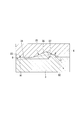
図1は、実施形態に係る照明装置1の二面図である。
照明装置1は、フロントライト式の表示構造2を備えた照明装置1(例えば、フロントライト照明式反射型液晶ディスプレイ)である。フロントライト式の照明装置1では、バックライト式の照明装置1とは異なり、光源7が常に光を照射する必要がないため、消費電力が少ない。このような消費電力が少ないフロントライト式の照明装置1(以下、単に照明装置1という場合がある。)は、例えば自転車や二輪車、自動車、列車、船舶、飛行機、登山用具等などで用いられる。
図1は、実施形態に係る照明装置1の二面図である。
照明装置1は、フロントライト式の表示構造2を備えた照明装置1(例えば、フロントライト照明式反射型液晶ディスプレイ)である。フロントライト式の照明装置1では、バックライト式の照明装置1とは異なり、光源7が常に光を照射する必要がないため、消費電力が少ない。このような消費電力が少ないフロントライト式の照明装置1(以下、単に照明装置1という場合がある。)は、例えば自転車や二輪車、自動車、列車、船舶、飛行機、登山用具等などで用いられる。
照明装置1は、表示構造2と、照明構造8と、を備える。
表示構造2は、反射型液晶ディスプレイなどの表示構造2である。表示構造2は、表示内容が表示される表示面21と、その反対側の背面22と、を有する。
表示構造2は、反射型液晶ディスプレイなどの表示構造2である。表示構造2は、表示内容が表示される表示面21と、その反対側の背面22と、を有する。
照明構造8は、表示構造2の表示面21側に配置されている。照明構造8は、導光板3と、透明板4と、第一結合部材5と、第二結合部材6と、光源7と、を有する。
[導光板]
導光板3は、表示構造2の表示面21と対向するように配置されている。導光板3は、例えばポリカーボネート等の樹脂材料により形成されている。導光板3の屈折率n2は、例えば1.585である。導光板3は、表示構造2側を向く第一面31と、第一面31とは反対側の第二面33と、を有する。第一面31は、平坦である。これにより、第一面31は、表示構造2の表示面21とほぼ平行に配置されている。第一面31は、表示面21と間隔をあけて対向している。第二面33は、平坦部34と、凸部35と、を有する。
導光板3は、表示構造2の表示面21と対向するように配置されている。導光板3は、例えばポリカーボネート等の樹脂材料により形成されている。導光板3の屈折率n2は、例えば1.585である。導光板3は、表示構造2側を向く第一面31と、第一面31とは反対側の第二面33と、を有する。第一面31は、平坦である。これにより、第一面31は、表示構造2の表示面21とほぼ平行に配置されている。第一面31は、表示面21と間隔をあけて対向している。第二面33は、平坦部34と、凸部35と、を有する。
平坦部34は、表示構造2の表示面21と略平行である。略平行とは、例えば平坦部34と表示面21とのなす角度が1°以下であることを意味する。より具体的には、本実施形態において、平坦部34は、第一面31の面方向に直交する側方から見て、導光板3の一側面13から他側面15へ向かって緩やかに傾斜している。平坦部34の表示面21に対する傾斜角度は1°以下である。
凸部35は、平坦部34から表示構造2と反対側に向かって突出形成されている。凸部35は、平坦部34の傾斜方向に並んで複数設けられている。凸部35は、導光板3の一側面13に略平行な方向(直交座標系19のY軸方向)に延びている。これにより、凸部35及び平坦部34は、導光板3の一側面13及び第一面31にそれぞれ直交する方向(直交座標系19のX軸方向)に交互に配置されている。平坦部34に対する凸部35の高さ寸法は、例えば10μm程度である。凸部35は、三角形状に形成されている。
図2は、図1のII部拡大図である。なお、図2では、説明を簡単にするために、導光板3における第二面33の平坦部34が表示構造2の表示面21と平行となるように図示している。この場合、導光板3の第一面31も表示面21と平行であるとする。
凸部35は、第一部分36と、第二部分37と、を有する。
凸部35は、第一部分36と、第二部分37と、を有する。
第一部分36は、導光板3の一側面13から他側面15へ向かうにつれて、表示構造2と反対側に向かって傾斜している。第一部分36の水平面に対する傾斜角度(すなわち、本実施形態では表示面21に対する傾斜角度)は、詳しくは後述する光源7から第二面33に照射された光の角度αよりも大きい角度とされている。
第二部分37は、導光板3の一側面13から他側面15へ向かうにつれて、表示構造2側に向かって傾斜している。第二部分37の水平面に対する傾斜角度(すなわち、本実施形態では表示面21に対する傾斜角度)は、βとされている。
このように、第一部分36及び第二部分37により形成された凸部35は、導光板3のプリズムとして機能する。
第二部分37は、導光板3の一側面13から他側面15へ向かうにつれて、表示構造2側に向かって傾斜している。第二部分37の水平面に対する傾斜角度(すなわち、本実施形態では表示面21に対する傾斜角度)は、βとされている。
このように、第一部分36及び第二部分37により形成された凸部35は、導光板3のプリズムとして機能する。
[透明板]
図1に戻って、透明板4は、導光板3に対して、表示構造2と反対側に配置されている。透明板4は、上面41(導光板3と反対側の面)及び下面42(導光板3と対向する面)が平坦に形成された平板状である。透明板4は、表示構造2の表示面21とほぼ平行に配置されている。透明板4は、導光板3の第二面33と間隔をあけて対向配置されている。透明板4の上面41は、外界(大気)に面している。透明板4は、例えば硬質ガラス等の材料により形成されている。透明板4は、例えば保護ガラスやタッチパネル等である。透明板4の屈折率n3は、例えば1.52である。このように形成された透明板4は、導光板3の第二面33に形成された凹凸形状を覆うことにより、照明装置1の表面を平坦にするとともに、導光板3を保護する役目を担っている。
図1に戻って、透明板4は、導光板3に対して、表示構造2と反対側に配置されている。透明板4は、上面41(導光板3と反対側の面)及び下面42(導光板3と対向する面)が平坦に形成された平板状である。透明板4は、表示構造2の表示面21とほぼ平行に配置されている。透明板4は、導光板3の第二面33と間隔をあけて対向配置されている。透明板4の上面41は、外界(大気)に面している。透明板4は、例えば硬質ガラス等の材料により形成されている。透明板4は、例えば保護ガラスやタッチパネル等である。透明板4の屈折率n3は、例えば1.52である。このように形成された透明板4は、導光板3の第二面33に形成された凹凸形状を覆うことにより、照明装置1の表面を平坦にするとともに、導光板3を保護する役目を担っている。
[第一結合部材]
第一結合部材5は、表示構造2と導光板3との間に配置されている。第一結合部材5は、表示構造2の表示面21と導光板3の第一面31との両方にそれぞれ接触している。第一結合部材5は、例えば表示構造2と導光板3とを貼り合わせるために用いられた接着剤が硬化したものである。第一結合部材5は、例えばシリコーンである。第一結合部材5の屈折率n1は、例えば1.41である。
第一結合部材5は、表示構造2と導光板3との間に配置されている。第一結合部材5は、表示構造2の表示面21と導光板3の第一面31との両方にそれぞれ接触している。第一結合部材5は、例えば表示構造2と導光板3とを貼り合わせるために用いられた接着剤が硬化したものである。第一結合部材5は、例えばシリコーンである。第一結合部材5の屈折率n1は、例えば1.41である。
[第二結合部材]
第二結合部材6は、導光板3と透明板4との間に配置されている。第二結合部材6は、導光板3の第二面33と透明板4の下面42との両方にそれぞれ接触している。第二結合部材6の下面(導光板3と対向する面)は、導光板3の凹凸形状に対応する凹凸形状に形成されている。第二結合部材6は、例えば導光板3と透明板4とを貼り合わせるために用いられた接着剤が硬化したものである。第一結合部材5及び第二結合部材6は同じ材料である。すなわち、第二結合部材6の屈折率n1は1.41である。このように、第二結合部材6の屈折率n1は、導光板3の屈折率n2及び透明板4の屈折率n3よりも低い。
第二結合部材6は、導光板3と透明板4との間に配置されている。第二結合部材6は、導光板3の第二面33と透明板4の下面42との両方にそれぞれ接触している。第二結合部材6の下面(導光板3と対向する面)は、導光板3の凹凸形状に対応する凹凸形状に形成されている。第二結合部材6は、例えば導光板3と透明板4とを貼り合わせるために用いられた接着剤が硬化したものである。第一結合部材5及び第二結合部材6は同じ材料である。すなわち、第二結合部材6の屈折率n1は1.41である。このように、第二結合部材6の屈折率n1は、導光板3の屈折率n2及び透明板4の屈折率n3よりも低い。
なお、第二結合部材6及び導光板3の屈折率は他の値であってもよい。例えば、第二結合部材6の屈折率n1は、1.3≦n1<1.5の範囲で任意の値に設定されてもよい。また、例えば、導光板3の屈折率n2は、1.5≦n2≦1.7の範囲で任意の値に設定されてもよい。また、例えば、透明板4の屈折率n3は、1.3≦n3≦1.7の範囲で任意の値に設定されてもよい。第二結合部材6の屈折率n1と導光板3の屈折率n2との差が大きいほど、照明の利用効率が高くなる。また、第一結合部材5と第二結合部材6とは別の材料であってもよい。
[光源]
光源7は、導光板3の一側面13を照らすように配置される。具体的に、光源7は、導光板3の一側面13に沿って配置されており、この一側面13を全体的に照らすとともに、一側面13から他側面15へ向かう方向に沿って導光板3の内部に光9を入射させる。ここで、表示構造2に到達する外光が強い場合に、表示構造2の表示内容は、外光によって読み取り可能である。一方、表示構造2に到達する外光が弱い場合に、表示構造2の表示内容は、光源7からの光9によって読み取り可能である。
光源7は、導光板3の一側面13を照らすように配置される。具体的に、光源7は、導光板3の一側面13に沿って配置されており、この一側面13を全体的に照らすとともに、一側面13から他側面15へ向かう方向に沿って導光板3の内部に光9を入射させる。ここで、表示構造2に到達する外光が強い場合に、表示構造2の表示内容は、外光によって読み取り可能である。一方、表示構造2に到達する外光が弱い場合に、表示構造2の表示内容は、光源7からの光9によって読み取り可能である。
[光路]
次に、光源7から照射された光9の進路(光路)について説明する。
光9は導光板3の一側面13から入射し、導光板3内を進む。このとき、表示面21に対する光9の照射角度はα(図2参照)となるように設定されている。光源7から導光板3内へ出射された光9(91)は、導光板3の第二面33に最初に到達した際に、凸部35の第二部分37で全反射され、導光板3の第一面31に向かって進む。光9は凸部35の第二部分37で全反射することにより、導光板3の法線に近づくように向きを変える。
次に、光源7から照射された光9の進路(光路)について説明する。
光9は導光板3の一側面13から入射し、導光板3内を進む。このとき、表示面21に対する光9の照射角度はα(図2参照)となるように設定されている。光源7から導光板3内へ出射された光9(91)は、導光板3の第二面33に最初に到達した際に、凸部35の第二部分37で全反射され、導光板3の第一面31に向かって進む。光9は凸部35の第二部分37で全反射することにより、導光板3の法線に近づくように向きを変える。
その後、第二部分37で全反射された光9(92)は、導光板3の第一面31に到達した際に、第一面31を透過して第一面31から導光板3の外部へ出射されるとともに、第一結合部材5に入射する。その後、光9(92)は、表示構造2に入射し、表示内容を含む光9(93)として矢印17に示す範囲で透明板4の上面から出射し、観測者の目10によって観測される。光9がこのような進路を取ることによって、光源7からの光9で表示構造2を照らした場合に画像コントラストが向上する。また、導光板3への入射光がこのような経路をたどるため、光源7の光9の利用効率が向上する。
ここで、図2に示すように、光源7から出射されて導光板3内を進む光9(91)の表示面21とのなす角度をαとする。第二部分37と表示面21とのなす角度をβとする。このとき、α及びβは、第二結合部材6の屈折率n1及び導光板3の屈折率n2を用いて、
α+β≦90°-arcsin(n1/n2)・・・式(1)
を満足するように設定される。式(1)を満たすことにより、光源7から出射された光9(91)は、第二部分37で全反射する。
α+β≦90°-arcsin(n1/n2)・・・式(1)
を満足するように設定される。式(1)を満たすことにより、光源7から出射された光9(91)は、第二部分37で全反射する。
さらに、第二部分37で全反射されて第一面31に向かう光9(92)の表示面21とのなす角度をγとする。このとき、γは、上述のα及びβを用いて、
γ≦α+2β・・・式(2)
を満足するように決定される。
γ≦α+2β・・・式(2)
を満足するように決定される。
[作用、効果]
次に、上述の照明装置1の作用、効果について説明する。
本実施形態の照明装置1によれば、光源7から導光板3に入射した光9(91)は、導光板3の第二面33に設けられた第二部分37で反射した後、第一面31から第一結合部材5に入射する。その後、光9は、第一結合部材5を透過して表示構造2に入射し、表示内容を含む光9(93)として再び導光板3に入射し、導光板3の第二面33から第二結合部材6及び透明板4を透過して透明板4の上面41から出射される。透明板4の上面41から出射された光9(93)は、観測者の目10によって観測される。光9がこのような経路を取ることにより、導光板3の側方に配置された光源7からの光9で表示構造2を照らすことができる。ここで、観測者の目10側に設けられた透明板4の上面41は平坦に形成されているので、外光の散乱による画像のコントラストの劣化を抑制できる。また、導光板3のプリズムの干渉色(虹ムラ)により表示された画像の見た目品質が低下するのを抑制できる。よって、画像のコントラストを向上するとともに、光の干渉色(虹ムラ)の発生を抑制し、画像の見た目品質を向上できる。
次に、上述の照明装置1の作用、効果について説明する。
本実施形態の照明装置1によれば、光源7から導光板3に入射した光9(91)は、導光板3の第二面33に設けられた第二部分37で反射した後、第一面31から第一結合部材5に入射する。その後、光9は、第一結合部材5を透過して表示構造2に入射し、表示内容を含む光9(93)として再び導光板3に入射し、導光板3の第二面33から第二結合部材6及び透明板4を透過して透明板4の上面41から出射される。透明板4の上面41から出射された光9(93)は、観測者の目10によって観測される。光9がこのような経路を取ることにより、導光板3の側方に配置された光源7からの光9で表示構造2を照らすことができる。ここで、観測者の目10側に設けられた透明板4の上面41は平坦に形成されているので、外光の散乱による画像のコントラストの劣化を抑制できる。また、導光板3のプリズムの干渉色(虹ムラ)により表示された画像の見た目品質が低下するのを抑制できる。よって、画像のコントラストを向上するとともに、光の干渉色(虹ムラ)の発生を抑制し、画像の見た目品質を向上できる。
導光板3の第二面33側には、第二結合部材6を介して透明板4が配置されるので、導光板3が外界に露出する場合と比較して、透明板4により導光板3を保護できる。これにより、導光板3の経年劣化を抑制し、導光板3の耐久性を向上できる。また、導光板3の性能を高い状態に維持できるので、照明装置1の寿命を向上できる。さらに、導光板3の第二面33に形成された凹凸形状を埋めるように第二結合部材6及び透明板4が張り合わされて平坦にされているので、導光板3の凸部35が露出する場合と比較して、外光の散乱を抑えることができる。よって、画像のコントラストの低下や虹ムラの発生を抑制し、表示面21全体を均一に照らすことができる。
したがって、フロントライト式の表示構造2を有する照明装置1において、画像のコントラスト低下や虹ムラの発生を抑制し、耐久性を向上した照明装置1を提供できる。
したがって、フロントライト式の表示構造2を有する照明装置1において、画像のコントラスト低下や虹ムラの発生を抑制し、耐久性を向上した照明装置1を提供できる。
光源7から導光板3に入射した光9(91)は、第二部分37で全反射し、全反射した光9(93)が第一面31から表示面21側に向かって出射される。このように、光9は、導光板3の第二面33で全反射してから出射されるので、光源7からの光9の利用率を向上できる。
また、光源7から導光板3に入射した光9(91)は、第二部分37で全反射された後、第一面31で透過されて表示面21に出射される。よって、光源7からの光9の利用率を向上できる。
また、光源7から導光板3に入射した光9(91)は、第二部分37で全反射された後、第一面31で透過されて表示面21に出射される。よって、光源7からの光9の利用率を向上できる。
第二結合部材6の屈折率をn1とし、導光板3の屈折率をn2とし、表示面21に対する導光板3内を伝搬する光9(91)の角度をαとし、表示面21に対する第二部分37の傾斜角度をβとし、第二部分37で全反射した光9(92)の表示面21に対する反射角度をγとしたとき、α、β及びγは、それぞれ式(1)及び式(2)を満足する。これにより、第二部分37において光9を効率的に全反射させることができる。また、表示内容を含む光9(93)を観測者の目10が観測可能な範囲内に出射することができる。よって、光源7からの光9の利用効率を向上し、表示性能の優れた照明装置1とすることができる。
なお、本発明の技術範囲は上述した実施形態に限定されるものではなく、本発明の趣旨を逸脱しない範囲において種々の変更を加えることが可能である。
例えば、上述した実施形態では、第一結合部材5が表示構造2の表示面21に接合されているが、これに代えて、第一結合部材5と表示面21との間に、光利用効率を向上するためのフィルム等が配置されてもよい。
例えば、上述した実施形態では、第一結合部材5が表示構造2の表示面21に接合されているが、これに代えて、第一結合部材5と表示面21との間に、光利用効率を向上するためのフィルム等が配置されてもよい。
その他、本発明の趣旨を逸脱しない範囲で、上述した実施形態における構成要素を周知の構成要素に置き換えることは適宜可能であり、また、上述した実施形態を適宜組み合わせても構わない。
上述した照明装置1によれば、フロントライト式の表示構造を有する照明装置において、画像のコントラスト低下や虹ムラの発生を抑制し、耐久性を向上することができる。
ここで、太陽光など強い外光が当たる屋外用途のディスプレイにおいて、スマートフォンに代表されるようなバックライト式透過型液晶ディスプレイでは、画像光が強い外光に負けて見えなくなってしまう問題がある。強い外光の下でのみの使用であれば照明装置を持たない反射型液晶ディスプレイで事足りるが、現在のほとんどのディスプレイの用途では、暗所でも画像が視認できるようにする必要がある。
上述した照明装置1を用いたフロントライト式反射型液晶ディスプレイによれば、画像の劣化(プリズムによる外光の散乱や干渉による虹むら)が抑制され、導光板3が透明板4で保護され耐久性が向上でき、導光板3の上面にタッチパネルなどが貼り合わせされたとしても導光板3の性能が変化しない。さらに、外光があれば照明の必要が無いため、バックライト式透過型液晶ディスプレイと比較して消費電力が1/50と小さくて済み、外光の強い明所及び外光の無い暗所の両方で初めて過不足なく使用できるディスプレイである。これにより、以下の特殊用途で応用できる。具体的には、例えば屋外デジタルサイネージや自転車、自動車、二輪車、重機、船舶、航空機、電力供給が困難な登山用の端末、災害時の端末、工事現場のタブレットPC、ガス・電気・水道の検診端末、宅配便の端末等に応用でき、長期にわたり全世界で活用される照明装置1とすることができる。
ここで、太陽光など強い外光が当たる屋外用途のディスプレイにおいて、スマートフォンに代表されるようなバックライト式透過型液晶ディスプレイでは、画像光が強い外光に負けて見えなくなってしまう問題がある。強い外光の下でのみの使用であれば照明装置を持たない反射型液晶ディスプレイで事足りるが、現在のほとんどのディスプレイの用途では、暗所でも画像が視認できるようにする必要がある。
上述した照明装置1を用いたフロントライト式反射型液晶ディスプレイによれば、画像の劣化(プリズムによる外光の散乱や干渉による虹むら)が抑制され、導光板3が透明板4で保護され耐久性が向上でき、導光板3の上面にタッチパネルなどが貼り合わせされたとしても導光板3の性能が変化しない。さらに、外光があれば照明の必要が無いため、バックライト式透過型液晶ディスプレイと比較して消費電力が1/50と小さくて済み、外光の強い明所及び外光の無い暗所の両方で初めて過不足なく使用できるディスプレイである。これにより、以下の特殊用途で応用できる。具体的には、例えば屋外デジタルサイネージや自転車、自動車、二輪車、重機、船舶、航空機、電力供給が困難な登山用の端末、災害時の端末、工事現場のタブレットPC、ガス・電気・水道の検診端末、宅配便の端末等に応用でき、長期にわたり全世界で活用される照明装置1とすることができる。
1…照明装置
2…表示構造
3…導光板
4…透明板
5…第一結合部材
6…第二結合部材
7…光源
9…光
13…一側面(導光板の側面)
21…表示面
31…第一面
33…第二面
34…平坦部
35…凸部
36…第一部分
37…第二部分
2…表示構造
3…導光板
4…透明板
5…第一結合部材
6…第二結合部材
7…光源
9…光
13…一側面(導光板の側面)
21…表示面
31…第一面
33…第二面
34…平坦部
35…凸部
36…第一部分
37…第二部分
Claims (5)
- 表示面を有する表示構造と、
前記表示構造の前記表示面側に配置される導光板と、
前記表示構造と前記導光板との間に配置される第一結合部材と、
前記導光板に対して前記表示構造と反対側に配置される透明板と、
前記導光板と前記透明板との間に配置される第二結合部材と、
前記導光板の側面を照らすように光を照射する光源と、
を備え、
前記導光板は、前記第一結合部材に接する第一面と、前記第二結合部材に接する第二面と、を有し、
前記導光板の前記第一面は平坦であり、
前記導光板の前記第二面は、前記表示面と略平行な平坦部と、前記平坦部から前記第二結合部材側に突出する凸部と、を有し、
前記凸部は、前記光源の照射方向の上流から下流へ向かうにつれて前記第二結合部材側に傾斜する第一部分と、前記照射方向の上流から下流へ向かうにつれて前記第一結合部材側に傾斜する第二部分と、を有し、
前記導光板は、前記第二部分において、前記光源から照射されて前記第二面に到達する前記光を全反射させるとともに、前記第二部分で全反射された前記光を前記第一面から前記導光板の外部へ出射させ、かつ、前記第二部分で全反射された前記光を前記第一面で透過させるように形成されており、
前記第一結合部材及び前記第二結合部材の屈折率をn1とし、
前記導光板の屈折率をn2とし、
前記表示面に対する前記導光板内を伝搬する前記光の角度をαとし、
前記表示面に対する前記第二部分の傾斜角度をβとし、
前記第二部分で全反射した前記光の前記表示面に対する反射角度をγとしたとき、
α+β≦90°-arcsin(n1/n2)、かつ
γ≦α+2β
を満足することを特徴とする照明装置。 - 表示面を有する表示構造と、
前記表示構造の前記表示面側に配置される導光板と、
前記表示構造と前記導光板との間に配置される第一結合部材と、
前記導光板に対して前記表示構造と反対側に配置される透明板と、
前記導光板と前記透明板との間に配置される第二結合部材と、
前記導光板の側面を照らすように光を照射する光源と、
を備え、
前記導光板は、前記第一結合部材に接する第一面と、前記第二結合部材に接する第二面と、を有し、
前記導光板の前記第一面は平坦であり、
前記導光板の前記第二面は、前記表示面と略平行な平坦部と、前記平坦部から前記第二結合部材側に突出する凸部と、を有し、
前記凸部は、前記光源の照射方向の上流から下流へ向かうにつれて前記第二結合部材側に傾斜する第一部分と、前記照射方向の上流から下流へ向かうにつれて前記第一結合部材側に傾斜する第二部分と、を有することを特徴とする照明装置。 - 前記導光板は、前記第二部分において、前記光源から照射されて前記第二面に到達する前記光を全反射させるとともに、前記第二部分で全反射された前記光を前記第一面から前記導光板の外部へ出射させるように形成されていることを特徴とする請求項2に記載の照明装置。
- 前記導光板は、前記第二部分で全反射された前記光を前記第一面で透過させるように形成されていることを特徴とする請求項3に記載の照明装置。
- 前記第一結合部材及び前記第二結合部材の屈折率をn1とし、
前記導光板の屈折率をn2とし、
前記表示面に対する前記導光板内を伝搬する前記光の角度をαとし、
前記表示面に対する前記第二部分の傾斜角度をβとし、
前記第二部分で全反射した前記光の前記表示面に対する反射角度をγとしたとき、
α+β≦90°-arcsin(n1/n2)、かつ
γ≦α+2β
を満足することを特徴とする請求項2から請求項4のいずれか1項に記載の照明装置。
Priority Applications (4)
| Application Number | Priority Date | Filing Date | Title |
|---|---|---|---|
| CN201980098610.0A CN114174904A (zh) | 2019-08-08 | 2019-08-08 | 照明装置 |
| PCT/JP2019/031491 WO2021024484A1 (ja) | 2019-08-08 | 2019-08-08 | 照明装置 |
| JP2021537543A JPWO2021024484A1 (ja) | 2019-08-08 | 2019-08-08 | |
| US17/630,224 US20220283469A1 (en) | 2019-08-08 | 2019-08-08 | Illumination device |
Applications Claiming Priority (1)
| Application Number | Priority Date | Filing Date | Title |
|---|---|---|---|
| PCT/JP2019/031491 WO2021024484A1 (ja) | 2019-08-08 | 2019-08-08 | 照明装置 |
Publications (1)
| Publication Number | Publication Date |
|---|---|
| WO2021024484A1 true WO2021024484A1 (ja) | 2021-02-11 |
Family
ID=74503058
Family Applications (1)
| Application Number | Title | Priority Date | Filing Date |
|---|---|---|---|
| PCT/JP2019/031491 Ceased WO2021024484A1 (ja) | 2019-08-08 | 2019-08-08 | 照明装置 |
Country Status (4)
| Country | Link |
|---|---|
| US (1) | US20220283469A1 (ja) |
| JP (1) | JPWO2021024484A1 (ja) |
| CN (1) | CN114174904A (ja) |
| WO (1) | WO2021024484A1 (ja) |
Cited By (1)
| Publication number | Priority date | Publication date | Assignee | Title |
|---|---|---|---|---|
| CN116033792A (zh) * | 2021-10-25 | 2023-04-28 | 乐金显示有限公司 | 有机发光二极管显示器 |
Citations (2)
| Publication number | Priority date | Publication date | Assignee | Title |
|---|---|---|---|---|
| JP2000292789A (ja) * | 1999-04-09 | 2000-10-20 | Sharp Corp | 照明装置及びそれを備えた表示装置 |
| JP2002008424A (ja) * | 2000-04-18 | 2002-01-11 | Matsushita Electric Ind Co Ltd | 反射型画面照明装置 |
Family Cites Families (5)
| Publication number | Priority date | Publication date | Assignee | Title |
|---|---|---|---|---|
| DE10000300A1 (de) * | 1999-06-11 | 2000-12-14 | Mannesmann Vdo Ag | Flüssigkristallanzeige |
| JP3456976B2 (ja) * | 2000-03-31 | 2003-10-14 | 三菱電機株式会社 | フロントライト、反射型液晶表示装置および携帯情報端末 |
| JP2002196331A (ja) * | 2000-12-27 | 2002-07-12 | Kyocera Corp | フロントライトユニット |
| JP2003131226A (ja) * | 2001-10-26 | 2003-05-08 | Matsushita Electric Ind Co Ltd | 反射型液晶表示装置 |
| CN109521515A (zh) * | 2019-01-02 | 2019-03-26 | 合肥京东方光电科技有限公司 | 导光板及其制作方法、背光模组和显示装置 |
-
2019
- 2019-08-08 CN CN201980098610.0A patent/CN114174904A/zh active Pending
- 2019-08-08 JP JP2021537543A patent/JPWO2021024484A1/ja active Pending
- 2019-08-08 US US17/630,224 patent/US20220283469A1/en not_active Abandoned
- 2019-08-08 WO PCT/JP2019/031491 patent/WO2021024484A1/ja not_active Ceased
Patent Citations (2)
| Publication number | Priority date | Publication date | Assignee | Title |
|---|---|---|---|---|
| JP2000292789A (ja) * | 1999-04-09 | 2000-10-20 | Sharp Corp | 照明装置及びそれを備えた表示装置 |
| JP2002008424A (ja) * | 2000-04-18 | 2002-01-11 | Matsushita Electric Ind Co Ltd | 反射型画面照明装置 |
Cited By (1)
| Publication number | Priority date | Publication date | Assignee | Title |
|---|---|---|---|---|
| CN116033792A (zh) * | 2021-10-25 | 2023-04-28 | 乐金显示有限公司 | 有机发光二极管显示器 |
Also Published As
| Publication number | Publication date |
|---|---|
| US20220283469A1 (en) | 2022-09-08 |
| JPWO2021024484A1 (ja) | 2021-02-11 |
| CN114174904A (zh) | 2022-03-11 |
Similar Documents
| Publication | Publication Date | Title |
|---|---|---|
| US11143872B2 (en) | Waveguide and video image display device | |
| CN108490692B (zh) | 背光模块 | |
| US8541934B2 (en) | Display device | |
| US9194995B2 (en) | Compact illumination module for head mounted display | |
| CN104064118A (zh) | 显示装置及其前光模块 | |
| JP5872206B2 (ja) | プロジェクション・システム | |
| CN102520549B (zh) | 透明显示器 | |
| CN104880825A (zh) | 一种平视显示的重影消除方法 | |
| CN205679890U (zh) | 一种曲面液晶显示屏及显示装置 | |
| KR20160092968A (ko) | 표시 패널 유닛 및 표시 장치 | |
| TW202206863A (zh) | 前光模組及其反射式顯示裝置 | |
| WO2021024484A1 (ja) | 照明装置 | |
| EP1664867A2 (en) | Backlight device | |
| CN115631679A (zh) | 防窥显示装置 | |
| TW201632784A (zh) | 照明裝置、顯示裝置及攜帶用電子機器 | |
| CN103995389B (zh) | 一种透明显示装置 | |
| CN208429022U (zh) | 一种车载后视镜 | |
| CN206863267U (zh) | 前置面光源、带前置面光源的电子图像装置及静态图像板 | |
| WO2012099123A1 (ja) | 導光板、面光源装置及び透過型画像表示装置 | |
| US20060250818A1 (en) | Backlight device | |
| US10012835B2 (en) | Image display device | |
| US20140063841A1 (en) | Front light module | |
| CN112946910A (zh) | 一种具有裸眼3d显示效果的仪表 | |
| JP3672038B2 (ja) | 液晶表示装置 | |
| US20210286122A1 (en) | Illumination structure |
Legal Events
| Date | Code | Title | Description |
|---|---|---|---|
| 121 | Ep: the epo has been informed by wipo that ep was designated in this application |
Ref document number: 19940724 Country of ref document: EP Kind code of ref document: A1 |
|
| ENP | Entry into the national phase |
Ref document number: 2021537543 Country of ref document: JP Kind code of ref document: A |
|
| NENP | Non-entry into the national phase |
Ref country code: DE |
|
| 122 | Ep: pct application non-entry in european phase |
Ref document number: 19940724 Country of ref document: EP Kind code of ref document: A1 |