WO2021024460A1 - Sphygmomanomètre - Google Patents
Sphygmomanomètre Download PDFInfo
- Publication number
- WO2021024460A1 WO2021024460A1 PCT/JP2019/031393 JP2019031393W WO2021024460A1 WO 2021024460 A1 WO2021024460 A1 WO 2021024460A1 JP 2019031393 W JP2019031393 W JP 2019031393W WO 2021024460 A1 WO2021024460 A1 WO 2021024460A1
- Authority
- WO
- WIPO (PCT)
- Prior art keywords
- pulse wave
- sphygmomanometer
- meter
- blood
- light
- Prior art date
Links
- 230000017531 blood circulation Effects 0.000 claims abstract description 68
- 230000036772 blood pressure Effects 0.000 claims abstract description 46
- 238000004364 calculation method Methods 0.000 claims abstract description 37
- 210000005259 peripheral blood Anatomy 0.000 claims abstract description 24
- 239000011886 peripheral blood Substances 0.000 claims abstract description 24
- 210000004369 blood Anatomy 0.000 claims abstract description 23
- 239000008280 blood Substances 0.000 claims abstract description 23
- 238000000605 extraction Methods 0.000 claims abstract description 15
- 239000000284 extract Substances 0.000 claims abstract description 7
- 230000002452 interceptive effect Effects 0.000 claims description 9
- 210000000707 wrist Anatomy 0.000 claims description 9
- 230000001678 irradiating effect Effects 0.000 claims description 5
- 230000001427 coherent effect Effects 0.000 claims description 3
- 238000010009 beating Methods 0.000 claims 1
- 230000003287 optical effect Effects 0.000 abstract description 84
- 238000004891 communication Methods 0.000 description 44
- 238000005259 measurement Methods 0.000 description 25
- 210000004204 blood vessel Anatomy 0.000 description 20
- 238000010586 diagram Methods 0.000 description 18
- 238000012545 processing Methods 0.000 description 16
- 206010005746 Blood pressure fluctuation Diseases 0.000 description 9
- 238000009530 blood pressure measurement Methods 0.000 description 5
- 238000006243 chemical reaction Methods 0.000 description 5
- 238000000502 dialysis Methods 0.000 description 5
- 238000000034 method Methods 0.000 description 5
- 239000004065 semiconductor Substances 0.000 description 4
- 206010003210 Arteriosclerosis Diseases 0.000 description 3
- 206010020772 Hypertension Diseases 0.000 description 3
- 208000011775 arteriosclerosis disease Diseases 0.000 description 3
- 230000000747 cardiac effect Effects 0.000 description 3
- 230000007423 decrease Effects 0.000 description 3
- 206010012601 diabetes mellitus Diseases 0.000 description 3
- 239000004744 fabric Substances 0.000 description 3
- 230000006870 function Effects 0.000 description 3
- 230000005540 biological transmission Effects 0.000 description 2
- 230000002308 calcification Effects 0.000 description 2
- 210000000624 ear auricle Anatomy 0.000 description 2
- 238000012986 modification Methods 0.000 description 2
- 230000004048 modification Effects 0.000 description 2
- 102000001554 Hemoglobins Human genes 0.000 description 1
- 108010054147 Hemoglobins Proteins 0.000 description 1
- 239000000853 adhesive Substances 0.000 description 1
- 230000001070 adhesive effect Effects 0.000 description 1
- 230000032683 aging Effects 0.000 description 1
- 229910052782 aluminium Inorganic materials 0.000 description 1
- XAGFODPZIPBFFR-UHFFFAOYSA-N aluminium Chemical compound [Al] XAGFODPZIPBFFR-UHFFFAOYSA-N 0.000 description 1
- XNEFYCZVKIDDMS-UHFFFAOYSA-N avobenzone Chemical compound C1=CC(OC)=CC=C1C(=O)CC(=O)C1=CC=C(C(C)(C)C)C=C1 XNEFYCZVKIDDMS-UHFFFAOYSA-N 0.000 description 1
- 229960005193 avobenzone Drugs 0.000 description 1
- 230000008859 change Effects 0.000 description 1
- 229920001940 conductive polymer Polymers 0.000 description 1
- 238000010276 construction Methods 0.000 description 1
- 230000006837 decompression Effects 0.000 description 1
- 230000003247 decreasing effect Effects 0.000 description 1
- 238000011161 development Methods 0.000 description 1
- 230000018109 developmental process Effects 0.000 description 1
- 230000035487 diastolic blood pressure Effects 0.000 description 1
- 201000010099 disease Diseases 0.000 description 1
- 208000037265 diseases, disorders, signs and symptoms Diseases 0.000 description 1
- 230000000694 effects Effects 0.000 description 1
- 229920001971 elastomer Polymers 0.000 description 1
- 239000000806 elastomer Substances 0.000 description 1
- 238000005516 engineering process Methods 0.000 description 1
- 210000003743 erythrocyte Anatomy 0.000 description 1
- 239000000835 fiber Substances 0.000 description 1
- 238000001914 filtration Methods 0.000 description 1
- 230000010354 integration Effects 0.000 description 1
- 230000003907 kidney function Effects 0.000 description 1
- 239000004973 liquid crystal related substance Substances 0.000 description 1
- 230000007774 longterm Effects 0.000 description 1
- 239000000463 material Substances 0.000 description 1
- 238000000691 measurement method Methods 0.000 description 1
- 229910052751 metal Inorganic materials 0.000 description 1
- 239000002184 metal Substances 0.000 description 1
- 238000012806 monitoring device Methods 0.000 description 1
- 238000012544 monitoring process Methods 0.000 description 1
- 230000010349 pulsation Effects 0.000 description 1
- 230000002040 relaxant effect Effects 0.000 description 1
- 230000004043 responsiveness Effects 0.000 description 1
- 238000005070 sampling Methods 0.000 description 1
- 238000001228 spectrum Methods 0.000 description 1
- 229910001220 stainless steel Inorganic materials 0.000 description 1
- 239000010935 stainless steel Substances 0.000 description 1
- 230000000638 stimulation Effects 0.000 description 1
- 229920003002 synthetic resin Polymers 0.000 description 1
- 239000000057 synthetic resin Substances 0.000 description 1
- 230000035488 systolic blood pressure Effects 0.000 description 1
- 210000003371 toe Anatomy 0.000 description 1
- 238000010200 validation analysis Methods 0.000 description 1
- 239000002550 vasoactive agent Substances 0.000 description 1
Images


Classifications
-
- A—HUMAN NECESSITIES
- A61—MEDICAL OR VETERINARY SCIENCE; HYGIENE
- A61B—DIAGNOSIS; SURGERY; IDENTIFICATION
- A61B5/00—Measuring for diagnostic purposes; Identification of persons
- A61B5/02—Detecting, measuring or recording pulse, heart rate, blood pressure or blood flow; Combined pulse/heart-rate/blood pressure determination; Evaluating a cardiovascular condition not otherwise provided for, e.g. using combinations of techniques provided for in this group with electrocardiography or electroauscultation; Heart catheters for measuring blood pressure
- A61B5/021—Measuring pressure in heart or blood vessels
- A61B5/02108—Measuring pressure in heart or blood vessels from analysis of pulse wave characteristics
- A61B5/02125—Measuring pressure in heart or blood vessels from analysis of pulse wave characteristics of pulse wave propagation time
-
- A—HUMAN NECESSITIES
- A61—MEDICAL OR VETERINARY SCIENCE; HYGIENE
- A61B—DIAGNOSIS; SURGERY; IDENTIFICATION
- A61B5/00—Measuring for diagnostic purposes; Identification of persons
- A61B5/02—Detecting, measuring or recording pulse, heart rate, blood pressure or blood flow; Combined pulse/heart-rate/blood pressure determination; Evaluating a cardiovascular condition not otherwise provided for, e.g. using combinations of techniques provided for in this group with electrocardiography or electroauscultation; Heart catheters for measuring blood pressure
- A61B5/024—Detecting, measuring or recording pulse rate or heart rate
- A61B5/02416—Detecting, measuring or recording pulse rate or heart rate using photoplethysmograph signals, e.g. generated by infrared radiation
- A61B5/02427—Details of sensor
-
- A—HUMAN NECESSITIES
- A61—MEDICAL OR VETERINARY SCIENCE; HYGIENE
- A61B—DIAGNOSIS; SURGERY; IDENTIFICATION
- A61B5/00—Measuring for diagnostic purposes; Identification of persons
- A61B5/02—Detecting, measuring or recording pulse, heart rate, blood pressure or blood flow; Combined pulse/heart-rate/blood pressure determination; Evaluating a cardiovascular condition not otherwise provided for, e.g. using combinations of techniques provided for in this group with electrocardiography or electroauscultation; Heart catheters for measuring blood pressure
- A61B5/024—Detecting, measuring or recording pulse rate or heart rate
- A61B5/0245—Detecting, measuring or recording pulse rate or heart rate by using sensing means generating electric signals, i.e. ECG signals
-
- A—HUMAN NECESSITIES
- A61—MEDICAL OR VETERINARY SCIENCE; HYGIENE
- A61B—DIAGNOSIS; SURGERY; IDENTIFICATION
- A61B5/00—Measuring for diagnostic purposes; Identification of persons
- A61B5/02—Detecting, measuring or recording pulse, heart rate, blood pressure or blood flow; Combined pulse/heart-rate/blood pressure determination; Evaluating a cardiovascular condition not otherwise provided for, e.g. using combinations of techniques provided for in this group with electrocardiography or electroauscultation; Heart catheters for measuring blood pressure
- A61B5/026—Measuring blood flow
- A61B5/0261—Measuring blood flow using optical means, e.g. infrared light
-
- A—HUMAN NECESSITIES
- A61—MEDICAL OR VETERINARY SCIENCE; HYGIENE
- A61B—DIAGNOSIS; SURGERY; IDENTIFICATION
- A61B5/00—Measuring for diagnostic purposes; Identification of persons
- A61B5/68—Arrangements of detecting, measuring or recording means, e.g. sensors, in relation to patient
- A61B5/6801—Arrangements of detecting, measuring or recording means, e.g. sensors, in relation to patient specially adapted to be attached to or worn on the body surface
- A61B5/6802—Sensor mounted on worn items
- A61B5/681—Wristwatch-type devices
-
- A—HUMAN NECESSITIES
- A61—MEDICAL OR VETERINARY SCIENCE; HYGIENE
- A61B—DIAGNOSIS; SURGERY; IDENTIFICATION
- A61B5/00—Measuring for diagnostic purposes; Identification of persons
- A61B5/72—Signal processing specially adapted for physiological signals or for diagnostic purposes
- A61B5/7271—Specific aspects of physiological measurement analysis
- A61B5/7278—Artificial waveform generation or derivation, e.g. synthesising signals from measured signals
-
- A—HUMAN NECESSITIES
- A61—MEDICAL OR VETERINARY SCIENCE; HYGIENE
- A61B—DIAGNOSIS; SURGERY; IDENTIFICATION
- A61B7/00—Instruments for auscultation
- A61B7/02—Stethoscopes
- A61B7/04—Electric stethoscopes
Definitions
- the present invention relates to a sphygmomanometer.
- the oscillometric method has a high affinity with fully automatic measurement and digital measurement. Therefore, with a conventional sphygmomanometer, when the user wraps the cuff around his arm and presses the measurement button, the cuff presses and depressurizes, measures and calculates the blood pressure, and digitally displays the result, which is highly convenient. There are many products.
- non-interfering light from LEDs etc. is irradiated to peripheral blood vessels, reflected light or transmitted light is detected by a light receiving element, and the pulse wave of the blood vessel is detected from the fluctuation of the received light amount.
- peripheral blood vessels are irradiated with light of a specific wavelength that is absorbed by erythrocyte hemoglobin, the amount of light received by the light receiving element without being absorbed reflects the amount of blood in the blood vessels, that is, fluctuations in blood vessel volume. Become.
- a pulse wave waveform (hereinafter, also referred to as "photoplex pulse wave (photopulse wave)") can be obtained based on the amount of light received received by the light receiving element. Further, such a measurement method is called a photoelectric conversion type volume pulse wave measurement (photoplethysmophram).
- the conventional optical sphygmomanometer obtains the blood pressure fluctuation based only on the photoelectric pulse wave, it may be difficult to measure the blood pressure accurately, for example, when the movement of the blood vessel of the user is small. It was. In particular, in patients with advanced arteriosclerosis or calcification of blood vessels due to diseases such as diabetes, the movement of blood vessels is small and it may be difficult to measure blood pressure.
- the present invention has been made to solve the above-mentioned problems, and an object of the present invention is to provide a sphygmomanometer that measures blood pressure more accurately.
- the blood pressure monitor includes a first measuring meter that measures the blood flow velocity in the peripheral blood vessel, a second measuring meter that measures the pulse wave waveform in the peripheral blood vessel, and a heart.
- a third measuring meter that measures data related to the beat of the heart, a feature point extraction unit that extracts feature points related to the beat from the data related to the beat of the heart, and a pulse wave waveform using the feature points. It includes a first calculation unit for obtaining a wave velocity, and a second calculation unit for obtaining a blood pressure based on the pulse wave velocity and the blood flow velocity.
- the pulse wave velocity is obtained from the pulse wave waveform in the peripheral blood vessel by using the feature points extracted from the data on the heartbeat, and the pulse wave velocity and the blood flow in the peripheral blood vessel are obtained. Since the blood pressure is calculated based on the speed, the blood pressure can be measured more accurately.
- FIG. 1 is a block diagram showing a configuration of an optical sphygmomanometer according to an embodiment of the present invention.
- FIG. 2 is a diagram for explaining an outline of an optical sphygmomanometer according to an embodiment of the present invention.
- FIG. 3 is a diagram for explaining an outline of an optical sphygmomanometer according to an embodiment of the present invention.
- FIG. 4 is a diagram for explaining an outline of the optical sphygmomanometer according to the embodiment of the present invention.
- FIG. 5 is a diagram for explaining an outline of the optical sphygmomanometer according to the embodiment of the present invention.
- FIG. 6 is a schematic view of the optical sensor device according to the first embodiment as viewed from the side.
- FIG. 6 is a schematic view of the optical sensor device according to the first embodiment as viewed from the side.
- FIG. 7 is a block diagram showing a configuration of the optical sensor device according to the first embodiment.
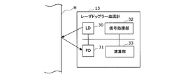
- FIG. 8 is a block diagram showing a configuration of a Doppler blood flow meter according to the first embodiment.
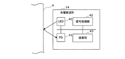
- FIG. 9 is a block diagram showing a configuration of a photoelectric pulse wave meter according to the first embodiment.
- FIG. 10 is a schematic external view showing the configuration of the electrocardiograph according to the first embodiment.
- FIG. 11 is a block diagram showing a functional configuration of the arithmetic unit according to the first embodiment.
- FIG. 12 is a block diagram showing an example of the hardware configuration of the arithmetic unit according to the first embodiment.
- FIG. 13 is a flowchart illustrating the operation of the optical sphygmomanometer according to the first embodiment.
- FIG. 14 is a schematic view of the optical sensor device according to the modified example of the first embodiment as viewed from the side.
- FIG. 15 is a block diagram showing a configuration of an optical sphygmomanometer according to a second embodiment.
- FIG. 16 is a schematic view of the optical sensor device according to the second embodiment as viewed from the side.
- FIG. 17 is a block diagram showing a configuration of an optical sphygmomanometer according to a third embodiment.
- FIG. 18 is a block diagram showing a configuration of a photoelectric pulse wave meter according to a third embodiment.
- the sphygmomanometer according to the present invention is an optical sphygmomanometer 1 that uses optical measurement.
- the outline of the optical sphygmomanometer 1 according to the present embodiment will be described.
- the relationship between blood pressure fluctuation and pulse wave can be described as follows (see Reference 1).
- C 2 ⁇ P / ⁇ ⁇ (V / ⁇ V) ⁇ ⁇ ⁇ (1)
- C pulse wave velocity
- P blood pressure
- ⁇ blood density
- V blood vessel volume
- ⁇ represents the amount of fluctuation.
- C 2 ⁇ P / 2 ⁇ ⁇ (D / ⁇ D) ⁇ ⁇ ⁇ (2)
- Non-Patent Document 1 Non-Patent Document 1
- Non-Patent Document 2 See Non-Patent Document 2.
- the pulse wave velocity C represented by the above equations (1) and (2) is relatively easy to obtain.
- the movement of blood vessels is relatively small.
- the optical sphygmomanometer 1 includes an optical sensor device 10 arranged on a user's finger or the like and a heart rate monitor (third measurement meter) for measuring an electrocardiographic waveform of the user. ) 11 and the arithmetic unit 12.
- the optical sensor device 10 includes a laser Doppler blood flow meter (first measuring meter) 13 and a photoelectric pulse wave meter (second measuring meter) 14.
- the laser Doppler blood flow meter 13 is a device that measures the blood flow of capillaries near the surface of the user's skin using interfering light, and when the light is applied to a moving object, the moving speed of the object is adjusted.
- the blood flow volume and blood flow velocity are obtained by using the Doppler effect in which the frequency of scattered light changes accordingly.
- the blood flow rate Q is expressed by the following equation (3).
- Q ⁇ fp ⁇ ⁇ ⁇ (3)
- the blood volume BV can be obtained by ⁇ p, so the blood flow velocity U can be obtained from the following equation (4).
- the relationship between the relational expression [D / ⁇ D] of the blood vessel diameter of the above-mentioned formula (2) and the blood flow measurement is that when the blood vessel expands, the cross-sectional area of the blood vessel increases, so that the blood flow velocity U decreases and the blood vessel When the blood vessels contract, the blood flow velocity U increases due to the decrease in the cross-sectional area of the blood vessels.
- the relational expression [D / ⁇ D] is replaced with the relational expression [-2U / ⁇ U] using the blood flow velocity U.
- the pulse wave velocity C is obtained by the photoelectric pulse wave meter 14 using the photoelectric conversion type volumetric pulse wave measurement.
- the propagation time difference of the pulse wave is measured, and as the starting point, for example, an electrocardiographic waveform or a heart sound type is used.
- 2 to 5 are schematic views showing the relationship between the electrocardiographic waveform (a), the heart sound type (b), and the pulse wave waveform (c).
- a heart sound type (b) I sound at the interval between the peak of the R wave of the electrocardiographic waveform (a) and the ST junction.
- a second sound is generated in the heart sound type (b) between the TUs of the electrocardiographic waveform (a).
- the start time of the ST joint is used as a starting time, that is, a feature point.
- the time of the feature point of the pulse wave waveform (c) extracted based on at least one of the electrocardiographic waveform (a) and the electrocardiographic waveform (b) is used as a reference in FIG.
- the pulse wave propagation time can be obtained from the time difference ⁇ t from the time of the feature point of the pulse wave waveform (c') shown in 1.
- FIG. 3 shows an example in which the feature points of the pulse wave waveform (c) are extracted based on the electrocardiographic waveform (a).
- FIG. 4 shows an example in which the feature points of the pulse wave waveform (c) are extracted based on the heart sound type (b).
- the time corresponding to the end time of the I sound and the start time of the II sound is used as a feature point of the pulse wave waveform (c).
- a comparison of two pulse wave waveforms (c) (c'') separated from the heart by a certain distance or more is also possible to obtain the time difference ⁇ t of the feature points from.
- the pulse wave velocity C can be obtained from the reciprocal of the propagation time. ..
- the measured value (blood pressure value) is calibrated and the values of the blood density ⁇ and the proportionality constant k are obtained to obtain more accuracy. It is possible to measure high blood pressure and blood pressure fluctuations.
- the optical sphygmomanometer 1 has the blood flow velocity U measured by the laser Doppler measurement and the pulse wave velocity obtained from the pulse wave waveform measured by the photoelectric pulse wave measurement.
- One of its characteristics is to obtain the blood pressure based on the velocity C.
- the optical sphygmomanometer 1 includes an optical sensor device 10, a heart rate monitor 11, and an arithmetic unit 12.
- an electrocardiograph is used as the heart rate monitor 11 that measures data related to the heartbeat of the user.
- the optical sensor device 10 is provided in a ring-shaped wearable terminal worn on a user's finger.
- the optical sensor device 10 includes a laser Doppler blood flow meter 13, a photoelectric pulse wave meter 14, a communication I / F 15, and a memory 16.
- FIG. 6 is a schematic view of the optical sensor device 10 as viewed from the side.
- the optical sensor device 10 is housed in the ring member B.
- the ring member B is formed in a tubular shape as shown in FIG.
- the laser Doppler blood flow meter 13 and the photoelectric pulse wave meter 14 are housed on the ventral side of the user's finger of the ring member B.
- the laser Doppler blood flow meter 13 and the photoelectric pulse wave meter 14 are integrally configured as shown in FIG.
- the ring member B can be formed in a band shape with a cloth or the like. For example, it can be fixed around the user's fingers by a hook-and-loop fastener. Alternatively, it can be fixed around the user's fingers by using a material such as elastic cloth. In this case, the laser Doppler blood flow meter 13 and the photoelectric pulse wave meter 14 can be fixed to the surface of the band-shaped ring member B on the user's finger side with an adhesive or the like.
- the ring member B can be made of a synthetic resin such as plastic or elastomer, or a non-magnetic metal such as aluminum or stainless steel.
- a recess is formed in the ring member B, and the laser Doppler blood flow meter 13 and the photoelectric pulse wave meter 14 can be fitted with the recess.
- the communication I / F15 is a communication control circuit for communicating with various external electronic devices via the communication network NW.
- the data measured by the laser Doppler blood flow meter 13 and the photoelectric pulse wave meter 14 is transmitted from the communication I / F 15 to the arithmetic unit 12 described later via the communication network NW.
- the communication I / F15 includes, for example, a communication interface circuit and an antenna corresponding to a wireless data communication standard such as Bluetooth (registered trademark), Bluetooth Low Energy, LTE, 3G, 4G, 5G, wireless LAN, or a wired data communication standard. Used.
- a wireless data communication standard such as Bluetooth (registered trademark), Bluetooth Low Energy, LTE, 3G, 4G, 5G, wireless LAN, or a wired data communication standard. Used.
- the memory 16 a semiconductor memory or the like is used.
- the memory 16 stores in advance programs for the calculation unit 33 of the laser Doppler blood flow meter 13, which will be described later, and the calculation unit 43 of the photoelectric pulse wave meter 14 to perform various controls and calculations. Further, the memory 16 has an area for recording the calibration data of the laser Doppler blood flow meter 13 and the photoelectric pulse wave meter 14.
- the laser Doppler blood flow meter 13 includes a semiconductor laser (first light source) LD30, a photodiode (first light receiving element) PD31, a signal processing unit 32, and a calculation unit 33. Be prepared.
- the LD30 emits coherent light toward the blood flowing through the peripheral blood vessels near the user's skin surface H.
- the LD30 uses a light source that emits a laser beam having an infrared wavelength.
- the PD31 receives scattered light generated by irradiating blood with coherent light and converts it into an electric signal by photoelectric conversion.
- the signal processing unit 32 converts an analog electric signal into a digital signal by amplifying the electric signal output from the PD 31, removing noise by filtering, and using a predetermined sampling frequency.
- the signal processing unit 32 includes, for example, an amplifier circuit, a filter, and an AD converter.
- the calculation unit 33 includes a processor such as an MPU.
- the calculation unit 33 obtains the blood flow velocity in the peripheral blood vessel based on the digital signal of the scattered light obtained by the signal processing unit 32. Specifically, the calculation unit 33 calculates the blood flow rate Q and the blood volume BV from the above-mentioned equation (3), and calculates the blood flow velocity U using the equation (4).
- the blood flow velocity obtained by the arithmetic unit 33 is transmitted from the communication I / F 15 to the arithmetic unit 12 via the communication network NW.
- the laser Doppler blood flow meter 13 includes a sensor drive control circuit (not shown), controls the light emission of the LD 30, and supplies a synchronization signal indicating the light emission timing of the LD 30 to the signal processing unit 32.
- the photoelectric pulse wave meter 14 includes, for example, an LED (second light source) 40, a photodiode (second light receiving element) PD 41, a signal processing unit 42, and a calculation unit 43.
- the LED 40 emits non-interfering light toward the blood flowing through the peripheral blood vessels near the user's skin surface H.
- the LED 40 uses a light source that emits light having a visible light wavelength.
- the PD41 receives the reflected light or scattered light generated by irradiating the blood with non-interfering light, or the transmitted light when the PD41 is in the transmission measurement arrangement, and converts it into an electric signal by photoelectric conversion.
- the integrally configured laser Doppler blood flow meter 13 and the photoelectric pulse wave meter 14 are housed in the ring member B.
- the PD 41 can be configured to be commonly used by the laser Doppler blood flow meter 13 and the photoelectric pulse wave meter 14.
- the optical measurement of each sensor is performed with a set time difference.
- the configuration can be such that the measurement is executed.
- the signal processing unit 42 has the same configuration as the signal processing unit 32, amplifies, filters, and AD-converts the electric signal obtained by the PD 41, and outputs a digital signal indicating reflected light, scattered light, or transmitted light. To do.
- the calculation unit 43 includes a processor such as an MPU similar to the above-mentioned calculation unit 33.
- the calculation unit 43 obtains a pulse wave waveform from the fluctuation amount of the digital signal indicating the reflected light or the like obtained by the signal processing unit 42.
- the pulse wave waveform in the peripheral blood vessel obtained by the arithmetic unit 43 is transmitted from the communication I / F 15 to the arithmetic unit 12 via the communication network NW.
- the calculation unit 43 can use a processor common to the calculation unit 33 of the laser Doppler blood flow meter 13.
- the photoelectric pulse wave meter 14 includes a sensor drive control circuit (not shown), controls the light emission of the LED 40, and supplies a synchronization signal indicating the light emission timing of the LED 40 to the signal processing unit 42.
- the photoelectric pulse wave meter 14 can use either transmission type measurement or reflection type measurement.
- the transmissive photoelectric pulse wave meter 14 it is preferable that the light from the LED 40 is a fingertip or an earlobe that easily penetrates the tissue of a living body.
- a shirt-type wearable device W is used as the heart rate monitor 11.
- the wearable device W has, for example, a structure in which a cloth coated with a conductive polymer on the fiber surface is arranged on a shirt.
- the wearable device W having such a cloth-type bioelectrode is worn by the user and comes into contact with the skin surface of the user, the electrocardiographic waveform of the user is measured.
- the heart rate monitor 11 includes a transmitter 11a, and transmits the measured electrocardiographic waveform of the user to the arithmetic unit 12 described later via the communication network NW.
- the transmitter 11a has, for example, a control board and a battery (not shown) including a communication I / F circuit, a memory, an arithmetic circuit, etc. conforming to a communication standard such as Bluetooth (registered trademark) and Bluetooth Low Energy.
- the heart rate monitor 11 is not limited to wireless communication, but can also perform wired communication with the arithmetic unit 12.
- the arithmetic unit 12 includes, for example, an acquisition unit 20, a feature point extraction unit 21, a first arithmetic unit 22, a second arithmetic unit 23, a storage unit 24, and an output unit 25.
- the acquisition unit 20 acquires the data measured by each of the optical sensor device 10 and the heart rate monitor 11 by wireless or wired communication. Specifically, the acquisition unit 20 acquires the blood flow velocity from the laser Doppler blood flow meter 13. Further, the acquisition unit 20 acquires a pulse wave waveform from the photoelectric pulse wave meter 14. Further, the acquisition unit 20 acquires an electrocardiographic waveform from the heart rate monitor 11. The data acquired by the acquisition unit 20 is stored in the storage unit 24.
- the feature point extraction unit 21 extracts feature points related to the heartbeat from the user's electrocardiographic waveform measured by the heart rate monitor 11. More specifically, as shown in FIGS. 2 and 3, for example, the feature point extraction unit 21 extracts the start time of the ST junction of the electrocardiographic waveform (a) as a starting time, that is, as a feature point. ..
- the first calculation unit 22 obtains the pulse wave velocity from the pulse wave waveform measured by the photoelectric pulse wave meter 14 by using the feature points of the electrocardiographic waveform extracted by the feature point extraction unit 21. More specifically, as shown in FIG. 3, the first calculation unit 22 starts from the start time of the ST junction of the electrocardiographic waveform, and from the time difference ⁇ t of the corresponding time in the pulse wave waveform, the pulse wave propagation time. To ask. Further, the first calculation unit 22 obtains the pulse wave velocity from the reciprocal of the pulse wave propagation time by making the blood vessel length through which the pulse wave propagates constant. The obtained pulse wave velocity is held in the storage unit 24.
- the second calculation unit 23 obtains the blood pressure based on the pulse wave velocity and the blood flow velocity measured by the laser Doppler blood flow meter 13. Specifically, the second calculation unit 23 substitutes the pulse wave velocity C, the blood flow velocity U, the blood density ⁇ obtained in advance, and the proportionality constant k by using the above equation (6) to obtain the blood pressure ( Blood pressure fluctuation) ⁇ P is calculated.
- the storage unit 24 stores the data acquired by the acquisition unit 20 from the optical sensor device 10 and the heart rate monitor 11. Further, the storage unit 24 stores the feature points related to the heartbeat extracted by the feature point extraction unit 21, the pulse wave velocity obtained by the first calculation unit 22, and the blood pressure obtained by the second calculation unit 23. In addition, the storage unit 24 stores the above-mentioned equation (6) for obtaining the blood pressure.
- the output unit 25 outputs the blood pressure (blood pressure fluctuation) obtained by the second calculation unit 23.
- the output unit 25 can display the blood pressure value on the display device 108 described later. Further, the output unit 25 can transmit the obtained blood pressure value to an external communication terminal device (not shown) or the like.
- the arithmetic unit 12 includes, for example, a processor 102, a main storage device 103, a communication I / F 104, an auxiliary storage device 105, an input / output I / O 106, and an input device 107, which are connected via a bus 101. It can be realized by a computer equipped with a display device 108 and a program that controls these hardware resources.
- the main storage device 103 is realized by, for example, a semiconductor memory such as SRAM, DRAM, and ROM.
- the main storage device 13 stores in advance programs for the processor 102 to perform various controls and calculations.
- the processor 102 and the main storage device 103 realize each function of the arithmetic unit 12 including the feature point extraction unit 21, the first arithmetic unit 22, and the second arithmetic unit 23 shown in FIG.
- the communication I / F 104 is an interface circuit for communicating with various external electronic devices via the communication network NW.
- the arithmetic unit 12 receives the data measured by the optical sensor device 10 and the heart rate monitor 11 via the communication I / F 104.
- the acquisition unit 20 shown in FIG. 11 is realized by the communication I / F 104.
- the communication I / F104 for example, an interface and an antenna corresponding to wireless data communication standards such as LTE, 3G, 4G, 5G, wireless LAN, Bluetooth (registered trademark), and Bluetooth Low Energy are used.
- the communication network NW includes, for example, WAN (Wide Area Network), LAN (Local Area Network), the Internet, a dedicated line, a wireless base station, a provider, and the like.
- the communication I / F 104 may also have a communication control circuit for performing wired communication.
- the auxiliary storage device 105 is composed of a readable and writable storage medium and a drive device for reading and writing various information such as programs and data to the storage medium.
- a semiconductor memory such as a hard disk or a flash memory can be used as the storage medium in the auxiliary storage device 105.
- the storage unit 24 described with reference to FIG. 11 is realized by the auxiliary storage device 105.
- the auxiliary storage device 105 has a program storage area for storing a program for the arithmetic unit 12 to perform a feature point extraction process, a pulse wave velocity calculation, and a blood pressure calculation.
- the auxiliary storage device 105 stores information regarding the formula (6) for obtaining blood pressure. Further, the auxiliary storage device 105 may have, for example, a backup area for backing up the above-mentioned data, programs, and the like.
- the input / output I / O 106 is composed of I / O terminals that input signals from external devices and output signals to external devices.
- the input device 107 is composed of a keyboard and a touch panel, and generates and outputs a signal corresponding to a key input or a touch device.
- the input device 107 can accept the input of the blood pressure value (calibration value) measured in advance in order to obtain the blood density ⁇ , the proportionality constant k, and the like.
- the display device 108 has a display screen such as a liquid crystal display.
- the display device 108 realizes the output unit 25 described with reference to FIG.
- the arithmetic unit 12 may be distributed not only by one computer but also by a plurality of computers connected to each other by a communication network NW.
- the processor 102 may be realized by hardware such as FPGA (Field-Programmable Gate Array), LSI (Large Scale Integration), and ASIC (Application Specific Integrated Circuit).
- the user wears a shirt-type wearable device W equipped with an electrocardiograph as a heart rate monitor 11 in advance, and executes the following processing with the optical sensor device 10 provided on the ring-type wearable terminal attached to the fingers. Will be done.
- the laser Doppler blood flow meter 13 measures the blood flow velocity in the peripheral blood vessels of the user's fingers (step S1).
- the photoelectric pulse wave meter 14 measures the pulse wave waveform in the peripheral blood vessels of the user's finger (step S2).
- the heart rate monitor 11 measures the electrocardiographic waveform of the user (step S3).
- step S2 and step S3 may be performed at the same time.
- the acquisition unit 20 acquires the blood flow velocity, the pulse wave waveform, and the electrocardiographic waveform measured in steps S1, S2, and S3 (step 4).
- the feature point extraction unit 21 extracts feature points related to the heartbeat from the electrocardiographic waveform (step S5). For example, the start time of the ST junction of the electrocardiographic waveform can be extracted as a feature point.
- the first calculation unit 22 calculates the pulse wave velocity from the pulse wave waveform starting from the time of the pulse wave waveform corresponding to the feature point of the electrocardiographic waveform extracted in step S5 (step S6). ..
- the second calculation unit 23 substitutes the pulse wave velocity C calculated in step S6, the blood flow velocity in the peripheral blood vessel, the blood density ⁇ obtained in advance, and the proportionality constant k into the equation (6). Then, the blood pressure (blood pressure fluctuation) is calculated (step S7).
- the output unit 25 displays the obtained blood pressure value on, for example, the display device 108 (step S8).
- the pulse wave velocity is obtained from the pulse wave waveform by using the feature points of the electrocardiographic waveform, and the pulse wave velocity and the pulse wave velocity are determined. Since the blood pressure is calculated based on the blood flow velocity in the peripheral blood vessels, it is possible to realize more accurate blood pressure measurement than the case based only on the photoelectric pulse wave.
- the optical sphygmomanometer 1 can accurately measure blood pressure without pressurizing a body part such as a user's arm, for example, a user can measure a blood vessel due to arteriosclerosis or the like. It is possible to provide the user with highly accurate blood pressure measurement even when the movement of the blood pressure is small.
- the optical sphygmomanometer 1 monitors blood pressure fluctuations without pressurization even in a situation where pressurization type blood pressure measurement is not desirable for a user such as during artificial dialysis. be able to.
- the optical sensor device 10 can be made smaller.
- the heart rate monitor 11 is a shirt-type wearable device W having a wearable electrode
- a 12-lead (12 channel) electrocardiograph (ECG) or an electrocardiograph using a patch electrode can also be used.
- FIG. 14 is a schematic view of the optical sensor device 10 according to the modified example as viewed from the side surface.
- the laser Doppler blood flow meter 13 and the photoelectric pulse wave meter 14 included in the optical sensor device 10 are integrally housed in the ring member B.
- the laser Doppler blood flow meter 13 and the photoelectric pulse wave meter 14 are separately housed in the ring member B.
- the laser Doppler blood flow meter 13 is housed on the ventral side of the user's finger in the ring member B.
- the laser Doppler blood flow meter 13 is housed on the ventral side of the finger having a higher capillary density, the laser Doppler measurement becomes easy and highly accurate.
- the photoelectric pulse wave meter 14 is housed in the ring member B on the back side of the user's fingers.
- each of the laser Doppler blood flow meter 13 and the photoelectric pulse wave meter 14 has PD31 and PD41.
- one common PD31 can be used instead of the separated PD31 and PD41.
- the blood pressure can be measured accurately as in the first embodiment. Can be done.
- the optical sensor device 10 is provided in a ring-type wearable terminal.
- the optical sensor device 10 is provided in the wristband type wearable terminal.
- a heart rate sensor 11A is used as the heart rate monitor 11.
- a configuration different from that of the first embodiment will be mainly described.
- FIG. 15 is a block diagram showing an outline of the optical sphygmomanometer 1A according to the present embodiment.
- the optical sphygmomanometer 1A includes a wristband type optical sensor device 10, a heart sound sensor 11A, and an arithmetic unit 12.
- the optical sensor device 10 is provided in, for example, a wristband type wearable terminal such as a smart watch.
- FIG. 16 is a schematic view of the optical sensor device 10 as viewed from the side. As shown in FIG. 16, the optical sensor device 10 is housed in a main body 100 worn on the user's wrist. Further, the main body 100 is fixed to the user's wrist by the band B1.
- the main body 100 includes a display 100a.
- the optical sensor device 10 is arranged on the back surface on the wrist side facing the front surface of the main body 100 where the display 100a is provided.
- the optical sensor device 10 has the same configuration as that of the first embodiment, and the laser Doppler blood flow meter 13 and the photoelectric pulse wave meter 14 have an integrated configuration. That is, the optical sensor device 10 includes LEDs 40, PDs (PD31, PD41), and LD30 as sensor elements.
- the LD30 of the laser Doppler blood flow meter 13 emits a laser beam having an infrared wavelength.
- the LED 40 of the photoelectric pulse wave meter 14 emits light having an infrared wavelength.
- a reflection type photoelectric pulse wave meter 14 for measuring the light reflected in the living body is used.
- the blood flow velocity and pulse wave waveform in the peripheral blood vessels measured by each of the laser Doppler blood flow meter 13 and the photoelectric pulse wave meter 14 are obtained from the communication I / F15 by wireless communication such as Bluetooth (registered trademark) and Bluetooth Low Energy. It is transmitted to the arithmetic unit 12.
- the heart sound sensor 11A includes a heart sound microphone, and for example, converts the detected heart sound into an electric signal.
- the heart sound sensor 11A is attached to the body surface of the user's chest, for example. Further, the heart sound sensor 11A is provided with a communication I / F, and transmits the measured cardiac sound waveform to the arithmetic unit 12 by wired communication or wireless communication such as Bluetooth (registered trademark) or Bluetooth Low Energy.
- the feature point extraction unit 21 extracts feature points related to the heartbeat from the heart sound waveform measured by the heart sound sensor 11A. Specifically, as shown in FIG. 4, the end time point of the I sound and the start time point of the II sound included in the heart sound type can be extracted as feature points.
- the first calculation unit 22 calculates the pulse wave velocity in the pulse wave waveform measured by the photoelectric pulse wave meter 14 based on the time corresponding to the cardiac sound type feature point extracted by the feature point extraction unit 21.
- the optical sphygmomanometer 1A is a peripheral blood vessel measured by attaching an optical sensor device 10 provided on a wristband type wearable terminal to a user's wrist.
- the user's blood pressure is calculated based on the blood flow velocity and pulse wave waveform of. Even when such a configuration is used, blood pressure can be measured with high accuracy.
- the characteristic points related to the heartbeat were extracted from the cardiac sound type measured by the heartbeat sensor 11A, and the pulse wave velocity was calculated from the pulse wave waveform. In this way, the pulse wave velocity can also be obtained by using the heart sound type.
- a heart rate monitor 11 for measuring an electrocardiographic waveform was used as a sensor for measuring data related to heartbeat. Further, in the second embodiment, the case where the heart sound sensor 11A for measuring the heart sound waveform is used has been described. On the other hand, in the third embodiment, the photoelectric pulse wave meter 11B is used as a sensor for measuring data related to the heartbeat.
- FIG. 17 is a block diagram showing an outline of the optical sphygmomanometer 1B according to the present embodiment.
- the optical sphygmomanometer 1B includes an optical sensor device 10 provided in a wristband type wearable terminal, a photoelectric pulse wave meter 11B, and an arithmetic unit 12.
- the configuration of the optical sensor device 10 and the arithmetic unit 12 is the same as that of the first and second embodiments.
- FIG. 18 is a block diagram showing the configuration of the photoelectric pulse wave meter 11B.
- the photoelectric pulse wave meter 11B is the same as the photoelectric pulse wave meter 14 included in the optical sensor device 10 described in the first and second embodiments. That is, the photoelectric pulse wave meter 11B includes a sensor element having an LED 50 and a PD 51.
- the LED 50 emits non-interfering light toward peripheral blood vessels near the surface of the user's skin.
- the PD51 receives reflected light, scattered light, or transmitted light generated by irradiating blood with non-interfering light, and converts it into an electric signal by photoelectric conversion.
- the photoelectric pulse wave meter 11B includes a signal processing unit 52 that amplifies, filters, and AD-converts the electric signal output from the PD 51. Further, the photoelectric pulse wave meter 11B includes a calculation unit 53 that obtains a pulse wave waveform based on a digital signal obtained by the signal processing unit 52.
- the photoelectric pulse wave meter 11B is located at a certain distance from the heart, such as the user's earlobe, and at a position different from the photoelectric pulse wave meter 14 placed on the user's wrist. Can be placed.
- the feature point extraction unit 21 is measured by the pulse wave waveform measured by the photoelectric pulse wave meter 11B and the photoelectric pulse wave meter 14 provided in the wristband type wearable terminal. By comparing with the pulse wave waveform, the feature points that are the starting points of the pulse wave propagation time are extracted.
- the photoelectric pulse wave meter 11B that measures the pulse wave waveform as the data related to the pulsation and the photoelectric pulse wave meter 14 included in the optical sensor device 10 are located at a certain distance from each other in the user's body. By arranging them, the pulse wave velocity is calculated more accurately.
- the photoelectric pulse wave meter 11B is provided with a communication I / F (not shown), and can transmit the pulse wave waveform measured to the arithmetic unit 12 by wired communication or wireless communication.
- photoelectric pulse wave meter 11B it is also possible to substitute the photoelectric pulse wave meter 11B with the photoelectric pulse wave meter 14 provided in the wristband type wearable terminal.
- a known algorithm can be applied to the pulse wave waveform measured by the photoelectric pulse wave meter 14, and feature points can be extracted from one pulse wave waveform.
- the optical sphygmomanometer 1B is provided with one photoelectric pulse wave meter 14, and the number of sensors in the optical sphygmomanometer 1B can be further reduced.
- the optical sphygmomanometer 1B As described above, according to the optical sphygmomanometer 1B according to the third embodiment, even when the photoelectric pulse wave meter 11B is used as the sensor for measuring the data related to the heartbeat, the blood pressure can be accurately measured. Can be measured.
- the optical sensor device 10 is not limited to being placed on the finger or wrist of the user, and can be placed on the upper arm of the user, for example.
- the optical sensor device 10 is provided on the cuff-type wearable terminal.
- the laser Doppler blood flow meter 13 is arranged in contact with a portion having a higher capillary density.
- the photoelectric pulse wave meter 11B can be placed on the toes of the user.
- the laser Doppler blood flow meter 13 and the photoelectric pulse wave meter 14 are a sensor element including LD30, LED40, and PD (PD31, PD41), signal processing units 32, 42, and a calculation unit 33. , 43 and 43 are integrally configured.
- the signal processing units 32 and 42 and the arithmetic units 33 and 43 may be configured to be included in the arithmetic unit 12.
- the ring member B or the main body 100 of the wristband type wearable terminal can be configured to include only the sensor element.
- each configuration and functional unit included in the optical sphygmomanometer 1 according to the described embodiment can be a distributed configuration on the communication network NW.
- the functional blocks, modules, and circuits described in connection with the embodiments disclosed herein include general-purpose processors, GPUs, digital signal processors (DSPs), application-specific integrated circuits (ASICs), FPGAs, or others. It can be performed using a programmable logic device, discrete gate or transistor logic, discrete hardware components, or any combination of the above designed to achieve the functions described above.
- microprocessor As a general-purpose processor, it is also possible to use a conventional processor, controller, microcontroller, or other control device instead.
- the processor can also be implemented, for example, as a combination of a DSP and a microprocessor, a plurality of microprocessors, one or more microprocessors connected to a DSP core, or a combination of computing devices having such an arbitrary configuration. Is.
- Optical blood pressure monitor 10 ... Optical sensor device, 11 ... Heart rate monitor, 11a ... Transmitter, 12 ... Computing device, 13 ... Laser Doppler blood flow meter, 14 ... Photoelectric pulse wave meter, 16 ... Memory, 20 ... Acquisition Unit, 21 ... feature point extraction unit, 22 ... first calculation unit, 23 ... second calculation unit, 24 ... storage unit, 25 ... output unit, 30 ... LD, 31,41 ... PD, 32, 42 ... signal processing unit , 33, 43 ... Arithmetic unit, 40 ... LED, W ... Wearable device, B ... Ring member, 101 ... Bus, 102 ... Processor, 103 ... Main storage device, 15, 104 ... Communication I / F, 105 ... Auxiliary storage device , 106 ... Input / output I / O, 107 ... Input device, 108 ... Display device.
Landscapes
- Health & Medical Sciences (AREA)
- Life Sciences & Earth Sciences (AREA)
- Engineering & Computer Science (AREA)
- Physics & Mathematics (AREA)
- Cardiology (AREA)
- Public Health (AREA)
- Heart & Thoracic Surgery (AREA)
- Medical Informatics (AREA)
- Molecular Biology (AREA)
- Surgery (AREA)
- Animal Behavior & Ethology (AREA)
- General Health & Medical Sciences (AREA)
- Biomedical Technology (AREA)
- Veterinary Medicine (AREA)
- Biophysics (AREA)
- Pathology (AREA)
- Physiology (AREA)
- Acoustics & Sound (AREA)
- Signal Processing (AREA)
- Hematology (AREA)
- Vascular Medicine (AREA)
- Artificial Intelligence (AREA)
- Computer Vision & Pattern Recognition (AREA)
- Psychiatry (AREA)
- Measuring Pulse, Heart Rate, Blood Pressure Or Blood Flow (AREA)
Abstract
L'invention concerne un sphygmomanomètre optique (1) comprenant : un débitmètre sanguin à effet Doppler laser (13) qui mesure la vitesse d'écoulement sanguin dans un vaisseau sanguin périphérique ; un dispositif de mesure d'onde d'impulsion photoélectrique (14) qui mesure la forme d'onde de l'onde d'impulsion dans le vaisseau sanguin périphérique ; un dispositif de mesure de fréquence cardiaque (11) qui mesure des données concernant un battement de coeur ; une unité d'extraction de point caractéristique (21) qui extrait un point caractéristique associé à un battement à partir des données concernant le battement cardiaque ; une première unité de calcul (22) qui obtient la vitesse de propagation d'onde d'impulsion à partir de la forme d'onde de l'onde d'impulsion à l'aide du point caractéristique ; et une seconde unité de calcul (23) qui obtient une pression sanguine sur la base de la vitesse d'onde d'impulsion et de la vitesse d'écoulement sanguin.
Priority Applications (3)
| Application Number | Priority Date | Filing Date | Title |
|---|---|---|---|
| JP2021538652A JP7235120B2 (ja) | 2019-08-08 | 2019-08-08 | 血圧計 |
| PCT/JP2019/031393 WO2021024460A1 (fr) | 2019-08-08 | 2019-08-08 | Sphygmomanomètre |
| US17/629,238 US20220265158A1 (en) | 2019-08-08 | 2019-08-08 | Sphygmomanometer |
Applications Claiming Priority (1)
| Application Number | Priority Date | Filing Date | Title |
|---|---|---|---|
| PCT/JP2019/031393 WO2021024460A1 (fr) | 2019-08-08 | 2019-08-08 | Sphygmomanomètre |
Publications (1)
| Publication Number | Publication Date |
|---|---|
| WO2021024460A1 true WO2021024460A1 (fr) | 2021-02-11 |
Family
ID=74503095
Family Applications (1)
| Application Number | Title | Priority Date | Filing Date |
|---|---|---|---|
| PCT/JP2019/031393 WO2021024460A1 (fr) | 2019-08-08 | 2019-08-08 | Sphygmomanomètre |
Country Status (3)
| Country | Link |
|---|---|
| US (1) | US20220265158A1 (fr) |
| JP (1) | JP7235120B2 (fr) |
| WO (1) | WO2021024460A1 (fr) |
Cited By (3)
| Publication number | Priority date | Publication date | Assignee | Title |
|---|---|---|---|---|
| CN114587309A (zh) * | 2022-03-16 | 2022-06-07 | 皖南医学院第一附属医院(皖南医学院弋矶山医院) | 一种血压测量方法及系统 |
| WO2023162757A1 (fr) * | 2022-02-28 | 2023-08-31 | 株式会社村田製作所 | Procédé de déduction de la fonction vasculaire |
| WO2023162756A1 (fr) * | 2022-02-28 | 2023-08-31 | 株式会社村田製作所 | Procédé d'estimation de l'hémodynamique |
Citations (4)
| Publication number | Priority date | Publication date | Assignee | Title |
|---|---|---|---|---|
| JP2014217707A (ja) * | 2013-05-11 | 2014-11-20 | 株式会社 ライフインターフェイス | 生体情報計測装置及び生体情報計測システム |
| WO2017047541A1 (fr) * | 2015-09-16 | 2017-03-23 | オムロンヘルスケア株式会社 | Dispositif, procédé et programme de mesure d'informations biométriques |
| JP2017127494A (ja) * | 2016-01-20 | 2017-07-27 | セイコーエプソン株式会社 | 血管弾性指標値測定装置、血圧測定装置及び血管弾性指標値測定方法 |
| JP2019058345A (ja) * | 2017-09-26 | 2019-04-18 | 富士通コネクテッドテクノロジーズ株式会社 | 生体情報測定装置及び生体情報測定方法 |
Family Cites Families (12)
| Publication number | Priority date | Publication date | Assignee | Title |
|---|---|---|---|---|
| JP3857788B2 (ja) * | 1997-09-01 | 2006-12-13 | テルモ株式会社 | 循環器情報計測システム |
| WO2003039326A2 (fr) * | 2001-11-07 | 2003-05-15 | Mills Alexander K | Methode de determination en continu et de façon non invasive des caracteristiques physiologiques |
| DE60207183T2 (de) * | 2001-12-10 | 2006-08-10 | Kabushiki Gaisha K-And-S | Vorrichtung zur Beobachtung biologischer Daten |
| EP1388321A1 (fr) * | 2002-08-09 | 2004-02-11 | Instrumentarium Oyj | Procédé et systeme de mesure continue et non invasive de la pression sanguine |
| ATE554704T1 (de) * | 2008-05-09 | 2012-05-15 | Koninkl Philips Electronics Nv | Kontaktlose atmungsüberwachung eines patienten und optischer sensor für eine photoplethysmographie-messung |
| JPWO2015049963A1 (ja) * | 2013-10-03 | 2017-03-09 | コニカミノルタ株式会社 | 生体情報測定装置および該方法 |
| TWI535416B (zh) * | 2015-06-02 | 2016-06-01 | 國立中央大學 | 非侵入且非加壓式血壓波量測裝置及方法 |
| JP6854612B2 (ja) * | 2015-10-06 | 2021-04-07 | 三星電子株式会社Samsung Electronics Co.,Ltd. | 生体情報測定装置及び生体情報測定方法並びにコンピュータ読み取り可能な記録媒体 |
| US10722177B2 (en) * | 2015-12-18 | 2020-07-28 | Verily Life Sciences Llc | Cardiovascular monitoring using combined measurements |
| US10213117B2 (en) * | 2016-02-18 | 2019-02-26 | Qualcomm Incorporated | Blood pressure estimation based on pulse wave velocity |
| JP6597410B2 (ja) * | 2016-03-04 | 2019-10-30 | セイコーエプソン株式会社 | 生体情報測定装置および生体情報測定方法 |
| JP6662459B2 (ja) * | 2016-08-10 | 2020-03-11 | 株式会社村田製作所 | 血圧状態測定装置 |
-
2019
- 2019-08-08 US US17/629,238 patent/US20220265158A1/en active Pending
- 2019-08-08 JP JP2021538652A patent/JP7235120B2/ja active Active
- 2019-08-08 WO PCT/JP2019/031393 patent/WO2021024460A1/fr active Application Filing
Patent Citations (4)
| Publication number | Priority date | Publication date | Assignee | Title |
|---|---|---|---|---|
| JP2014217707A (ja) * | 2013-05-11 | 2014-11-20 | 株式会社 ライフインターフェイス | 生体情報計測装置及び生体情報計測システム |
| WO2017047541A1 (fr) * | 2015-09-16 | 2017-03-23 | オムロンヘルスケア株式会社 | Dispositif, procédé et programme de mesure d'informations biométriques |
| JP2017127494A (ja) * | 2016-01-20 | 2017-07-27 | セイコーエプソン株式会社 | 血管弾性指標値測定装置、血圧測定装置及び血管弾性指標値測定方法 |
| JP2019058345A (ja) * | 2017-09-26 | 2019-04-18 | 富士通コネクテッドテクノロジーズ株式会社 | 生体情報測定装置及び生体情報測定方法 |
Cited By (4)
| Publication number | Priority date | Publication date | Assignee | Title |
|---|---|---|---|---|
| WO2023162757A1 (fr) * | 2022-02-28 | 2023-08-31 | 株式会社村田製作所 | Procédé de déduction de la fonction vasculaire |
| WO2023162756A1 (fr) * | 2022-02-28 | 2023-08-31 | 株式会社村田製作所 | Procédé d'estimation de l'hémodynamique |
| CN114587309A (zh) * | 2022-03-16 | 2022-06-07 | 皖南医学院第一附属医院(皖南医学院弋矶山医院) | 一种血压测量方法及系统 |
| CN114587309B (zh) * | 2022-03-16 | 2024-03-01 | 皖南医学院第一附属医院(皖南医学院弋矶山医院) | 一种血压测量方法及系统 |
Also Published As
| Publication number | Publication date |
|---|---|
| JP7235120B2 (ja) | 2023-03-08 |
| US20220265158A1 (en) | 2022-08-25 |
| JPWO2021024460A1 (fr) | 2021-02-11 |
Similar Documents
| Publication | Publication Date | Title |
|---|---|---|
| CN106618537B (zh) | 一种基于脉搏波传导的连续动态血压监测装置和方法 | |
| US20210244302A1 (en) | Methods to estimate the blood pressure and the arterial stiffness based on photoplethysmographic (ppg) signals | |
| JP6969561B2 (ja) | 血圧測定装置、血圧測定方法及び血圧測定プログラム | |
| US20150366469A1 (en) | System for measurement of cardiovascular health | |
| US20060084878A1 (en) | Personal computer-based vital signs monitor | |
| WO2022120656A1 (fr) | Procédé et appareil de mesure de la pression artérielle, et dispositif électronique | |
| Panula et al. | Advances in non-invasive blood pressure measurement techniques | |
| Marzorati et al. | Chest wearable apparatus for cuffless continuous blood pressure measurements based on PPG and PCG signals | |
| CN112426141B (zh) | 血压检测装置以及电子设备 | |
| JP2006239114A (ja) | カフレス電子血圧計 | |
| WO2002085203A1 (fr) | Dispositif d'estimation de forme d'onde de pression sanguine centrale et dispositif de detection de forme d'onde de pression sanguine peripherique | |
| JP7235120B2 (ja) | 血圧計 | |
| US10117598B1 (en) | Non-invasive wearable respiration rate monitoring system | |
| US20180206734A1 (en) | Wrist type apparatus for measurement of cardiovascular health, system, and method thereof | |
| CN112890790B (zh) | 一种穿戴式无创血压动态跟踪监测方法 | |
| Samartkit et al. | A non-invasive heart rate and blood pressure monitoring system using piezoelectric and photoplethysmographic sensors | |
| US20230293026A1 (en) | Photoplethysmography-based Blood Pressure Monitoring Device | |
| JP6615970B1 (ja) | 血圧推定装置および血圧推定プログラム | |
| Tanaka et al. | Accuracy assessment of a noninvasive device for monitoring beat-by-beat blood pressure in the radial artery using the volume-compensation method | |
| KR102272019B1 (ko) | 혈압 측정 시스템 및 이를 이용한 혈압 측정 방법 | |
| CN209863803U (zh) | 一种血压测量腕带设备 | |
| TWI644628B (zh) | 生理感測織物及其方法 | |
| JP7133576B2 (ja) | 位相差法による連続血圧測定システム | |
| JP2003000555A (ja) | 中枢血圧波形推定装置および末梢血圧波形検出装置 | |
| JP2004081285A (ja) | 携帯型血圧測定装置 |
Legal Events
| Date | Code | Title | Description |
|---|---|---|---|
| 121 | Ep: the epo has been informed by wipo that ep was designated in this application |
Ref document number: 19940858 Country of ref document: EP Kind code of ref document: A1 |
|
| ENP | Entry into the national phase |
Ref document number: 2021538652 Country of ref document: JP Kind code of ref document: A |
|
| NENP | Non-entry into the national phase |
Ref country code: DE |
|
| 122 | Ep: pct application non-entry in european phase |
Ref document number: 19940858 Country of ref document: EP Kind code of ref document: A1 |