WO2021020367A1 - Coated tool, and cutting tool comprising same - Google Patents
Coated tool, and cutting tool comprising same Download PDFInfo
- Publication number
- WO2021020367A1 WO2021020367A1 PCT/JP2020/028795 JP2020028795W WO2021020367A1 WO 2021020367 A1 WO2021020367 A1 WO 2021020367A1 JP 2020028795 W JP2020028795 W JP 2020028795W WO 2021020367 A1 WO2021020367 A1 WO 2021020367A1
- Authority
- WO
- WIPO (PCT)
- Prior art keywords
- protrusion
- layer
- protrusions
- intermediate layer
- gas
- Prior art date
Links
Images


Classifications
-
- C—CHEMISTRY; METALLURGY
- C23—COATING METALLIC MATERIAL; COATING MATERIAL WITH METALLIC MATERIAL; CHEMICAL SURFACE TREATMENT; DIFFUSION TREATMENT OF METALLIC MATERIAL; COATING BY VACUUM EVAPORATION, BY SPUTTERING, BY ION IMPLANTATION OR BY CHEMICAL VAPOUR DEPOSITION, IN GENERAL; INHIBITING CORROSION OF METALLIC MATERIAL OR INCRUSTATION IN GENERAL
- C23C—COATING METALLIC MATERIAL; COATING MATERIAL WITH METALLIC MATERIAL; SURFACE TREATMENT OF METALLIC MATERIAL BY DIFFUSION INTO THE SURFACE, BY CHEMICAL CONVERSION OR SUBSTITUTION; COATING BY VACUUM EVAPORATION, BY SPUTTERING, BY ION IMPLANTATION OR BY CHEMICAL VAPOUR DEPOSITION, IN GENERAL
- C23C16/00—Chemical coating by decomposition of gaseous compounds, without leaving reaction products of surface material in the coating, i.e. chemical vapour deposition [CVD] processes
- C23C16/22—Chemical coating by decomposition of gaseous compounds, without leaving reaction products of surface material in the coating, i.e. chemical vapour deposition [CVD] processes characterised by the deposition of inorganic material, other than metallic material
- C23C16/30—Deposition of compounds, mixtures or solid solutions, e.g. borides, carbides, nitrides
- C23C16/40—Oxides
-
- B—PERFORMING OPERATIONS; TRANSPORTING
- B23—MACHINE TOOLS; METAL-WORKING NOT OTHERWISE PROVIDED FOR
- B23B—TURNING; BORING
- B23B27/00—Tools for turning or boring machines; Tools of a similar kind in general; Accessories therefor
- B23B27/14—Cutting tools of which the bits or tips or cutting inserts are of special material
- B23B27/148—Composition of the cutting inserts
-
- C—CHEMISTRY; METALLURGY
- C23—COATING METALLIC MATERIAL; COATING MATERIAL WITH METALLIC MATERIAL; CHEMICAL SURFACE TREATMENT; DIFFUSION TREATMENT OF METALLIC MATERIAL; COATING BY VACUUM EVAPORATION, BY SPUTTERING, BY ION IMPLANTATION OR BY CHEMICAL VAPOUR DEPOSITION, IN GENERAL; INHIBITING CORROSION OF METALLIC MATERIAL OR INCRUSTATION IN GENERAL
- C23C—COATING METALLIC MATERIAL; COATING MATERIAL WITH METALLIC MATERIAL; SURFACE TREATMENT OF METALLIC MATERIAL BY DIFFUSION INTO THE SURFACE, BY CHEMICAL CONVERSION OR SUBSTITUTION; COATING BY VACUUM EVAPORATION, BY SPUTTERING, BY ION IMPLANTATION OR BY CHEMICAL VAPOUR DEPOSITION, IN GENERAL
- C23C16/00—Chemical coating by decomposition of gaseous compounds, without leaving reaction products of surface material in the coating, i.e. chemical vapour deposition [CVD] processes
- C23C16/02—Pretreatment of the material to be coated
- C23C16/0272—Deposition of sub-layers, e.g. to promote the adhesion of the main coating
-
- C—CHEMISTRY; METALLURGY
- C23—COATING METALLIC MATERIAL; COATING MATERIAL WITH METALLIC MATERIAL; CHEMICAL SURFACE TREATMENT; DIFFUSION TREATMENT OF METALLIC MATERIAL; COATING BY VACUUM EVAPORATION, BY SPUTTERING, BY ION IMPLANTATION OR BY CHEMICAL VAPOUR DEPOSITION, IN GENERAL; INHIBITING CORROSION OF METALLIC MATERIAL OR INCRUSTATION IN GENERAL
- C23C—COATING METALLIC MATERIAL; COATING MATERIAL WITH METALLIC MATERIAL; SURFACE TREATMENT OF METALLIC MATERIAL BY DIFFUSION INTO THE SURFACE, BY CHEMICAL CONVERSION OR SUBSTITUTION; COATING BY VACUUM EVAPORATION, BY SPUTTERING, BY ION IMPLANTATION OR BY CHEMICAL VAPOUR DEPOSITION, IN GENERAL
- C23C16/00—Chemical coating by decomposition of gaseous compounds, without leaving reaction products of surface material in the coating, i.e. chemical vapour deposition [CVD] processes
- C23C16/22—Chemical coating by decomposition of gaseous compounds, without leaving reaction products of surface material in the coating, i.e. chemical vapour deposition [CVD] processes characterised by the deposition of inorganic material, other than metallic material
- C23C16/30—Deposition of compounds, mixtures or solid solutions, e.g. borides, carbides, nitrides
- C23C16/36—Carbonitrides
-
- C—CHEMISTRY; METALLURGY
- C23—COATING METALLIC MATERIAL; COATING MATERIAL WITH METALLIC MATERIAL; CHEMICAL SURFACE TREATMENT; DIFFUSION TREATMENT OF METALLIC MATERIAL; COATING BY VACUUM EVAPORATION, BY SPUTTERING, BY ION IMPLANTATION OR BY CHEMICAL VAPOUR DEPOSITION, IN GENERAL; INHIBITING CORROSION OF METALLIC MATERIAL OR INCRUSTATION IN GENERAL
- C23C—COATING METALLIC MATERIAL; COATING MATERIAL WITH METALLIC MATERIAL; SURFACE TREATMENT OF METALLIC MATERIAL BY DIFFUSION INTO THE SURFACE, BY CHEMICAL CONVERSION OR SUBSTITUTION; COATING BY VACUUM EVAPORATION, BY SPUTTERING, BY ION IMPLANTATION OR BY CHEMICAL VAPOUR DEPOSITION, IN GENERAL
- C23C16/00—Chemical coating by decomposition of gaseous compounds, without leaving reaction products of surface material in the coating, i.e. chemical vapour deposition [CVD] processes
- C23C16/22—Chemical coating by decomposition of gaseous compounds, without leaving reaction products of surface material in the coating, i.e. chemical vapour deposition [CVD] processes characterised by the deposition of inorganic material, other than metallic material
- C23C16/30—Deposition of compounds, mixtures or solid solutions, e.g. borides, carbides, nitrides
- C23C16/40—Oxides
- C23C16/403—Oxides of aluminium, magnesium or beryllium
-
- C—CHEMISTRY; METALLURGY
- C23—COATING METALLIC MATERIAL; COATING MATERIAL WITH METALLIC MATERIAL; CHEMICAL SURFACE TREATMENT; DIFFUSION TREATMENT OF METALLIC MATERIAL; COATING BY VACUUM EVAPORATION, BY SPUTTERING, BY ION IMPLANTATION OR BY CHEMICAL VAPOUR DEPOSITION, IN GENERAL; INHIBITING CORROSION OF METALLIC MATERIAL OR INCRUSTATION IN GENERAL
- C23C—COATING METALLIC MATERIAL; COATING MATERIAL WITH METALLIC MATERIAL; SURFACE TREATMENT OF METALLIC MATERIAL BY DIFFUSION INTO THE SURFACE, BY CHEMICAL CONVERSION OR SUBSTITUTION; COATING BY VACUUM EVAPORATION, BY SPUTTERING, BY ION IMPLANTATION OR BY CHEMICAL VAPOUR DEPOSITION, IN GENERAL
- C23C28/00—Coating for obtaining at least two superposed coatings either by methods not provided for in a single one of groups C23C2/00 - C23C26/00 or by combinations of methods provided for in subclasses C23C and C25C or C25D
- C23C28/04—Coating for obtaining at least two superposed coatings either by methods not provided for in a single one of groups C23C2/00 - C23C26/00 or by combinations of methods provided for in subclasses C23C and C25C or C25D only coatings of inorganic non-metallic material
- C23C28/042—Coating for obtaining at least two superposed coatings either by methods not provided for in a single one of groups C23C2/00 - C23C26/00 or by combinations of methods provided for in subclasses C23C and C25C or C25D only coatings of inorganic non-metallic material including a refractory ceramic layer, e.g. refractory metal oxides, ZrO2, rare earth oxides
-
- C—CHEMISTRY; METALLURGY
- C23—COATING METALLIC MATERIAL; COATING MATERIAL WITH METALLIC MATERIAL; CHEMICAL SURFACE TREATMENT; DIFFUSION TREATMENT OF METALLIC MATERIAL; COATING BY VACUUM EVAPORATION, BY SPUTTERING, BY ION IMPLANTATION OR BY CHEMICAL VAPOUR DEPOSITION, IN GENERAL; INHIBITING CORROSION OF METALLIC MATERIAL OR INCRUSTATION IN GENERAL
- C23C—COATING METALLIC MATERIAL; COATING MATERIAL WITH METALLIC MATERIAL; SURFACE TREATMENT OF METALLIC MATERIAL BY DIFFUSION INTO THE SURFACE, BY CHEMICAL CONVERSION OR SUBSTITUTION; COATING BY VACUUM EVAPORATION, BY SPUTTERING, BY ION IMPLANTATION OR BY CHEMICAL VAPOUR DEPOSITION, IN GENERAL
- C23C28/00—Coating for obtaining at least two superposed coatings either by methods not provided for in a single one of groups C23C2/00 - C23C26/00 or by combinations of methods provided for in subclasses C23C and C25C or C25D
- C23C28/04—Coating for obtaining at least two superposed coatings either by methods not provided for in a single one of groups C23C2/00 - C23C26/00 or by combinations of methods provided for in subclasses C23C and C25C or C25D only coatings of inorganic non-metallic material
- C23C28/044—Coating for obtaining at least two superposed coatings either by methods not provided for in a single one of groups C23C2/00 - C23C26/00 or by combinations of methods provided for in subclasses C23C and C25C or C25D only coatings of inorganic non-metallic material coatings specially adapted for cutting tools or wear applications
-
- C—CHEMISTRY; METALLURGY
- C23—COATING METALLIC MATERIAL; COATING MATERIAL WITH METALLIC MATERIAL; CHEMICAL SURFACE TREATMENT; DIFFUSION TREATMENT OF METALLIC MATERIAL; COATING BY VACUUM EVAPORATION, BY SPUTTERING, BY ION IMPLANTATION OR BY CHEMICAL VAPOUR DEPOSITION, IN GENERAL; INHIBITING CORROSION OF METALLIC MATERIAL OR INCRUSTATION IN GENERAL
- C23C—COATING METALLIC MATERIAL; COATING MATERIAL WITH METALLIC MATERIAL; SURFACE TREATMENT OF METALLIC MATERIAL BY DIFFUSION INTO THE SURFACE, BY CHEMICAL CONVERSION OR SUBSTITUTION; COATING BY VACUUM EVAPORATION, BY SPUTTERING, BY ION IMPLANTATION OR BY CHEMICAL VAPOUR DEPOSITION, IN GENERAL
- C23C30/00—Coating with metallic material characterised only by the composition of the metallic material, i.e. not characterised by the coating process
- C23C30/005—Coating with metallic material characterised only by the composition of the metallic material, i.e. not characterised by the coating process on hard metal substrates
-
- B—PERFORMING OPERATIONS; TRANSPORTING
- B23—MACHINE TOOLS; METAL-WORKING NOT OTHERWISE PROVIDED FOR
- B23B—TURNING; BORING
- B23B2228/00—Properties of materials of tools or workpieces, materials of tools or workpieces applied in a specific manner
- B23B2228/10—Coatings
Definitions
- the present disclosure relates to a coating tool having a coating layer on the surface of a substrate and a cutting tool provided with the coating tool.
- Cemented carbide or cermet the substrate surface such as ceramics, coating tool such as a cutting tool to form a coated layer formed by laminating the Al 2 O 3 layer via the coupling film is known.
- Cutting tools are increasingly used for heavy intermittent cutting where a large impact is applied to the cutting edge with the recent increase in efficiency of cutting. Under such harsh cutting conditions, a large impact is applied to the coating layer, and chipping or peeling of the coating layer is likely to occur. Therefore, the coating layer is required to have improved fracture resistance in addition to wear resistance.
- Patent Document 1 describes that a protrusion having a hook-shaped tip is arranged at an interface in contact with the Al 2 O 3 layer.
- Patent Document 2 and Patent Document 3 at the interface in contact with the Al 2 O 3 layer, a composite protrusion having a large number of second protrusions is arranged on the side surface of the first protrusion extending in the stacking direction of the coating layer. It is stated that it should be done.
- the tips of the protrusions and composite protrusions described in Patent Document 1 and Patent Document 2 have an obtuse angle, and have a shape inferior in film formation property.
- the composite protrusions described in Patent Document 2 and Patent Document 3 do not have the first protrusion, but have only the composite protrusion, and also have a shape in which the film forming property is inferior.
- the coating tool of the present disclosure includes a substrate and a coating layer located on the surface of the substrate.
- the coating layer has a Ti-containing intermediate layer and an Al 2 O 3 layer.
- the Al 2 O 3 layer is located in contact with the intermediate layer at a position farther from the substrate than the intermediate layer.
- the intermediate layer has a plurality of first protrusions protruding toward the Al 2 O 3 layer. At least one of the plurality of first protrusions is a composite protrusion having a second protrusion protruding in a direction intersecting the protrusion direction of the first protrusion.
- the ratio of the composite protrusion to the plurality of first protrusions is 30% or less.
- the cutting tool of the present disclosure includes a holder extending from the first end toward the second end and having a pocket on the first end side, and the above-mentioned covering tool located in the pocket.
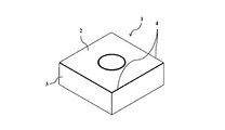
- the covering tool of the present disclosure has a plate shape having a substantially square main surface.
- the covering tool 1 has a first surface 2 and a second surface 3, and has a cutting edge 4 at least a part of a portion where the first surface 2 and the second surface 3 intersect.
- the first surface 2 is a surface called a rake surface
- the second surface 3 is a surface called a flank surface. Therefore, it can be said that the cutting edge 4 is provided at least a part of the portion where the rake face 2 and the flank surface 3 intersect.
- the covering tool 1 includes a base 5 and a coating layer 7 located on the surface of the base 5. ing.
- Examples of the material constituting the base 5 of the covering tool 1 include cemented carbide, ceramics, and metal.
- the hard alloy may be a cemented carbide containing tungsten carbide (WC) and an iron metal such as cobalt (Co) or nickel (Ni).
- a Ti-based cermet containing titanium carbonitride (TiCN) and an iron group metal such as cobalt (Co) or nickel (Ni) may be used.
- the ceramics may be Si 3 N 4 , Al 2 O 3 , diamond, cubic boron nitride (cBN).
- the metal may be carbon steel, high speed steel, or alloy steel.
- the substrate 5 when used as the covering tool 1, the substrate 5 may be made of cemented carbide or cermet in terms of fracture resistance and wear resistance.
- the coating layer 7 has an intermediate layer 9 containing Ti and an Al 2 O 3 layer 11.
- the Al 2 O 3 layer 11 is in contact with the intermediate layer 9 at a position far from the substrate 5 of the intermediate layer 9.
- the intermediate layer 9 in the covering tool 1 of the present disclosure is a layer having Ti, and may contain, for example, TiN, TiC, TiNO, and the like. Further, for example, Ti, C and N may be contained. In other words, the intermediate layer 9 may contain TiCN crystals. Further, the intermediate layer 9 may contain, for example, Ti, C, N and O. In other words, the intermediate layer 9 may contain TiCNO crystals. With such a configuration, the adhesion between the Al 2 O 3 layer 11 and the intermediate layer 9 is excellent.
- the covering tool 1 of the present disclosure has a plurality of first protrusions 13 projecting toward the Al 2 O 3 layer 11.
- the first protrusion 13 has a foot 13a which is a starting point of the protrusion of the first protrusion 13. Further, the first protrusion 13 has a tip 13b at a position farthest from the substrate 5. In other words, the first protrusion 13 extends from the base 13a toward the tip 13b.
- the first protrusion 13 typically has a triangular shape.
- the foot 13a refers to a position of the first protrusion 13 near the base 5.
- the foot 13a may be rephrased as the base of the triangle formed by the first protrusion 13.
- the first protrusion 13 has an acute angle at the tip 13b, a height of 10 nm or more, and the foot 13a of the plurality of first protrusions 13. It means that the ratio of the average heights of the plurality of first protrusions 13 to the average width is 0.6 or more.
- At least one of the plurality of first protrusions 13 is a composite protrusion 17 having a second protrusion 15 protruding in a direction intersecting the protrusion direction of the first protrusion 13. Is.
- all of the first protrusions 13 may be composite protrusions 17.
- those having the second protrusion 15 will be referred to as a composite protrusion 17.
- the compound protrusion 17 in the covering tool 1 of the present application means that the foot of the second protrusion 15 is separated from the foot of the first protrusion 13 as shown in FIG. In other words, a stack of a plurality of first protrusions 13 is not treated as a composite protrusion 17.
- the second protrusion 15 in the covering tool 1 of the present disclosure means that the height from the central portion of the base 15a of the second protrusion 15 which is the starting point of the protrusion of the second protrusion 15 to the tip 15b of the second protrusion 15 is defined as the height. It is 10 nm or more. That is, in other words, the minute unevenness existing on the side surface of the first protrusion 13 is not treated as the second protrusion 15 in the covering tool 1 of the present disclosure.
- the ratio of the composite protrusion 17 to the plurality of first protrusions 13 is 30% or less.
- the ratio of the composite protrusion 17 to the plurality of first protrusions 13 is 28.6%.
- the ratio of the composite protrusion 17 to the plurality of first protrusions 13 may be 5% or more. Further, the ratio of the composite protrusion 17 to the plurality of first protrusions 13 may be 20% or less.
- the number of the first protrusion 13 and the composite protrusion 17 may be measured by taking a 30,000-fold photograph using, for example, a scanning electron microscope or a transmission electron microscope.
- the ratio of the composite protrusion 17 to the plurality of first protrusions 13 may be measured by measuring about 50 to 100 first protrusions 13.
- the number of photographs to be taken may be appropriately determined according to the number of existing composite protrusions 17.
- other constituent requirements in the covering tool of the present disclosure may be measured in the same manner.
- the average number of the second protrusions 15 included in the composite protrusions 17 is 1.2 or less.
- the average number of the second protrusions 15 included in the composite protrusions 17 may be an average value of 50 composite protrusions 17.
- the ratio of the average height of the second protrusion 15 to the average width of the foot 15a of the second protrusion 15 in the covering tool 1 of the present disclosure is the ratio of the plurality of first protrusions 13 to the average width of the foot 13a of the plurality of first protrusions 13. It may be larger than the average height ratio.
- the ratio of the average height of the second protrusion 15 to the average width of the foot 15a of the second protrusion 15 is the average height from the central portion of the foot 15a of the second protrusion 15 to the tip 15b of the second protrusion 15. , The value divided by the average width of the foot 15a of the second protrusion 15. With such a configuration, the adhesion between the intermediate layer 9 and the Al 2 O 3 layer 11 is further excellent.
- the ratio of the average height of the plurality of first protrusions 13 to the average width of the foot 13a of the plurality of first protrusions 13 may be 1.2 or less. With such a configuration, the adhesion between the intermediate layer 9 and the Al 2 O 3 layer 11 is excellent.
- the ratio of the average height of the plurality of first protrusions 13 to the average width of the foot 13a of the plurality of first protrusions 13 may be 1.0 or less.
- the average width of the foot 13a of the first protrusion 13 may be 10 nm or more and 50 nm or less, and the average height of the first protrusion 13 may be 10 nm or more and 60 nm or less. With such a configuration, the adhesion between the intermediate layer 9 and the Al 2 O 3 layer 11 is excellent.
- the average width of the foot 13a may be 25 nm or more and 45 nm or less.
- the average height of the first protrusion 13 may be 10 nm or more and 50 nm or less.
- the average angle of the tip 13b of the first protrusion 13 may be 50 ° or more and 90 ° or less.
- excellent film forming property of the Al 2 O 3 layer 11 excellent adhesion of the intermediate layer 9 and the Al 2 O 3 layer 11.
- the average angle of the tip 13b of the first protrusion 13 may be 55 ° or more.
- the average angle of the tip 13b of the first protrusion 13 may be 80 ° or less.
- the composite protrusion 17 in the covering tool 1 of the present disclosure may have a third protrusion 19 protruding in a direction intersecting the protrusion direction of the second protrusion 15.
- the height of the third protrusion 19 is 10 nm or more.
- the minute unevenness existing on the side surface of the second protrusion 15 is not treated as the third protrusion 19 in the covering tool 1 of the present disclosure.
- Such minute irregularities do not substantially contribute to the adhesion between the intermediate layer 9 and the Al 2 O 3 layer 11.
- the coating layer 7 has the TiN layer 10a, the first TiCN layer 10b, the second TiCN layer 10c, the intermediate layer 9, and the Al 2 O 3 layer 11 in this order from the substrate 5. May have. With such a configuration, the covering tool 1 has a long life.
- the first TiCN layer 10b may be an MT-TiCN layer described later.
- the second TiCN layer 10c may be an HT-TiCN layer described later.
- a TiN layer or the like may be provided as a surface layer (not shown).
- the surface layer may be made of other materials other than titanium nitride, such as titanium carbonitride, titanium carbonate, and chromium nitride.
- the surface layer may be made of a colored material and may have a function of easily determining whether or not a cutting edge is used.
- the surface layer may be provided with a thickness of 0.1 ⁇ m to 3.0 ⁇ m.
- the first protrusion 13, the second protrusion 15, and the third protrusion 19 in the covering tool 1 of the present disclosure all contain Ti, C, and N, and may have the same composition. Further, the first protrusion 13, the second protrusion 15, and the third protrusion 19 all contain Ti, C, N, and O, and may have the same composition. If the compositions of the first protrusion 13, the second protrusion 15, and the third protrusion 19 are the same, cracks and breakage are less likely to occur between the first protrusion 13, the second protrusion 15, and the third protrusion 19, respectively.
- the adhesion between the intermediate layer 9 and the Al 2 O 3 layer 11 is higher than that in the case where the compositions of the above are different.
- compositions of the first protrusion 13, the second protrusion 15, and the third protrusion 19 are homogeneous means that the difference between the constituent components of each is 5% or less.
- each composition may be 3% or less. Further, it may be 1% or less.
- Such first protrusion 13, second protrusion 15 and third protrusion 19 can be obtained by using the same gas when forming the first protrusion 13, the second protrusion 15 and the third protrusion 19.
- compositions of the first protrusion 13 and the second protrusion 15 may be different, and the compositions of the second protrusion 15 and the third protrusion 19 may be different.
- the first protrusion 13 In order to form the first protrusion 13, the second protrusion 15, and the third protrusion 19 having different compositions, it is preferable to use gases having different compositions at the time of film formation.
- first protrusion 13 may not be formed perpendicular to the first surface 2 of the substrate 5, or may be inclined with respect to the first surface 2 of the substrate 5.
- the thickness of the intermediate layer 9 is 10 nm ⁇ 35 nm, without hardness of the intermediate layer 9 is decreased, and the Al 2 O 3 layer 11 is ⁇ -type crystal structure.
- the thickness of the intermediate layer 9 excludes the first protrusion 13, the second protrusion 15, and the third protrusion 19.
- the intermediate layer 9 may contain, for example, titanium in an amount of 30 to 70 atomic%, carbon in an amount of 1 to 70 atomic%, nitrogen in an amount of 1 to 35 atomic%, and oxygen in an amount of 3 to 20 atomic%. Further, aluminum may be further contained in an amount of 10 atomic% or less. Further, it may contain 1 to 10 atomic% of components such as chlorine and chromium. Further, the intermediate layer 9 may contain other trace components.
- the first protrusion 13, the second protrusion 15, and the third protrusion 19 may all have the same composition or may have the above-mentioned composition range.
- the intermediate layer having the first protrusion can be formed, for example, by forming a film on the surface of the substrate by a chemical vapor deposition (CVD) method under the following conditions.
- CVD chemical vapor deposition
- the substrate is set in the chamber of the film forming apparatus, for example, the film forming temperature is 900 ° C. to 990 ° C., the gas pressure is 15 kPa to 40 kPa, and the reaction gas composition is 3% by volume of titanium tetrachloride (TiCl 4 ) gas. ⁇ 15% by volume, methane (CH 4 ) gas 3% by volume to 10% by volume, nitrogen (N 2 ) gas 3% by volume to 50% by volume, carbon monoxide (CO) gas 0.2% by volume to 1 It is preferable to form a film with 0.0% by volume and the rest as hydrogen (H 2 ) gas. For the sake of convenience, this process is referred to as the first step of the film formation process of the intermediate layer.
- the film forming temperature is 900 ° C. to 990 ° C.
- the gas pressure is 15 kPa to 40 kPa
- the reaction gas composition is 3% by volume of titanium tetrachloride (TiCl 4 )
- the film formation time in this first step may be 20 minutes or more and 40 minutes or less.
- the nitrogen (N 2 ) gas having this reaction gas composition is 30% by volume to 50% by volume, the average width of the foot of the first protrusion tends to be wide, and the average height of the first protrusion tends to be short. In other words, under such conditions, it is easy to obtain a first protrusion that is thick, short, and hard to break.
- the film formation time in the previous step is preferably 20 minutes or more and 40 minutes or less. Under such film forming conditions, it is easy to form the first protrusions having an average foot spacing of 70 nm or more and 120 nm or less.
- the second protrusion is formed when the film formation temperature is lowered and the film formation temperature is in the range of 900 to 940 ° C. without changing the composition of the raw material gas.
- the film formation time may be 30 to 90 minutes in total with the previous step.
- the film formation time is extended in the latter stage of film formation of the intermediate layer, that is, in the process of forming the second protrusion, the number of the second protrusions increases, and the width and height tend to increase.
- a second protrusion whose protrusion direction extends toward the substrate is likely to be formed.
- a third protrusion protruding from the second protrusion is formed.
- the formation temperature of the Al 2 O 3 layer is 900 ° C. to 990 ° C.
- the gas pressure is 5 kPa to 20 kPa
- the composition of the reaction gas is 3.5 aluminum trichloride (AlCl 3 ) gas.
- AlCl 3 aluminum trichloride
- HCl hydrogen sulfide
- CO 2 carbon dioxide
- H hydrogen sulfide
- the gas may be formed as 0% by volume to 1.0% by volume, and the rest may be hydrogen (H 2 ) gas.
- the Al 2 O 3 layer may be made of ⁇ -alumina.
- the coating layer may have a TiN layer, a first TiCN layer, and a second TiCN layer in this order from the substrate. Then, an intermediate layer and an Al 2 O 3 layer may be provided on the second TiCN layer in this order. Further, a surface layer containing Ti and N may be further provided on the Al 2 O 3 layer.
- the film formation temperature is 800 ° C. to 940 ° C.
- the gas pressure is 8 kPa to 50 kPa
- the composition of the reaction gas is 0.5% by volume of titanium tetrachloride (TiCl 4 ) gas.
- the film may be formed with 10% by volume, nitrogen (N 2 ) gas at 10% by volume to 60% by volume, and the rest as hydrogen (H 2 ) gas.
- a first TiCN layer and a second TiCN layer may be provided on the TiN layer.
- the first TiCN layer may be a so-called MT (moderate temperature) -TiCN layer.
- MT-TiCN layer for example, a raw material containing titanium tetrachloride (TiCl 4 ) gas, nitrogen (N 2 ) gas, acetonitrile (CH 3 CN) gas and the like is used, and the film formation temperature is set to 780 ° C to 880 ° C.
- the thickness of the first TiCN layer formed by forming a film at a relatively low temperature is 2 ⁇ m to 15 ⁇ m, the wear resistance and fracture resistance of the first TiCN layer are high.
- the titanium nitride crystal contained in the first TiCN layer may be a columnar crystal elongated in the thickness direction of the coating layer.
- the second TiCN layer may be a so-called HT (high temperature) -TiCN layer.
- the HT-TiCN layer is formed by using, for example, titanium tetrachloride (TiCl 4 ) gas, nitrogen (N 2 ) gas, methane (CH 4 ) gas or the like as a raw material gas, and does not contain acetonitrile (CH 3 CN) gas.
- the film may be formed in a film temperature range of 900 ° C. to 1050 ° C. Further, the film may be formed at a temperature higher than that of the first TiCN layer.
- the thickness of the second TiCN layer may be 10 nm to 900 nm.
- titanium is 30 to 70 atomic%
- carbon is 15 to 35 atomic%
- nitrogen is 15 to 35 atomic%
- oxygen is 2 to 10 atomic%.
- the containing interface layer (not shown) may be arranged.
- the thickness of the interface layer may be 5 nm to 50 nm.
- the film formation temperature was 780 ° C to 880 ° C
- the gas pressure was 5 kPa to 25 kPa
- the reaction gas composition was 0.5% by volume to 10% by volume of titanium tetrachloride (TiCl 4 ) gas and nitrogen (N 2 ).
- the gas may be formed as 5% by volume to 60% by volume
- acetonitrile (CH 3 CN) gas may be formed as 0.1% by volume to 3.0% by volume
- the rest may be formed as hydrogen (H 2 ) gas.
- the average crystal width of the titanium nitride columnar crystals constituting the first TiCN layer is set on the surface side of the substrate side rather than the substrate side.
- the larger configuration can be used.
- the film formation temperature was 900 ° C to 990 ° C
- the gas pressure was 5 kPa to 40 kPa
- the composition of the reaction gas was 1% to 4% by volume of titanium tetrachloride (TiCl 4 ) gas and 5 volumes of nitrogen (N 2 ) gas.
- TiCl 4 titanium tetrachloride
- N 2 nitrogen
- methane (CH 4 ) gas may be 0.1% by volume to 10% by volume, and the rest may be hydrogen (H 2 ) gas.
- At least the cutting edge portion on the surface of the film-formed coating layer is polished.
- the cutting edge portion is smoothly processed, welding of the work material is suppressed, and the tool has further excellent fracture resistance.
- the cutting tool 101 of the present disclosure is, for example, a rod-shaped body extending from the first end (upper end in FIG. 5) to the second end (lower end in FIG. 5).
- the cutting tool 101 includes a holder 105 having a pocket 103 on the first end side (tip side) and the above-mentioned covering tool 1 located in the pocket 103. Since the cutting tool 101 includes the covering tool 1, stable cutting can be performed for a long period of time.
- the pocket 103 is a portion on which the covering tool 1 is mounted, and has a seating surface parallel to the lower surface of the holder 105 and a restraining side surface inclined with respect to the seating surface. Further, the pocket 103 is open on the first end side of the holder 105.
- the covering tool 1 is located in the pocket 103. At this time, the lower surface of the covering tool 1 may be in direct contact with the pocket 103, or a sheet (not shown) may be sandwiched between the covering tool 1 and the pocket 103.
- the covering tool 1 is attached to the holder 105 so that at least a part of the portion used as the cutting edge 7 at the ridge line where the first surface 3 and the second surface 5 intersect protrudes outward from the holder 105.
- the covering tool 1 is attached to the holder 105 by the fixing screw 107. That is, by inserting the fixing screw 107 into the through hole 17 of the covering tool 1, inserting the tip of the fixing screw 107 into the screw hole (not shown) formed in the pocket 103, and screwing the screw portions together.
- the covering tool 1 is attached to the holder 105.
- Steel, cast iron, etc. can be used as the material of the holder 105.
- steel having high toughness may be used.
- the cutting tool 101 used for so-called turning is illustrated.
- Examples of the turning process include inner diameter processing, outer diameter processing, and grooving processing.
- the cutting tool 101 is not limited to the one used for turning.
- the covering tool 1 of the above embodiment may be used as the cutting tool used for the milling process.
- a coating layer was formed on the above-mentioned cemented carbide substrate by a chemical vapor deposition (CVD) method.
- CVD chemical vapor deposition
- an intermediate layer and an Al 2 O 3 layer were directly formed on the substrate.
- a TiN layer was provided on the surface of the above-mentioned cemented carbide substrate, and a first TiCN layer, a second TiCN layer, an intermediate layer, and an Al 2 O 3 layer were provided on the TiN layer in this order.
- the film forming conditions for the intermediate layer of each sample are shown in Tables 1 and 2. In the film formation of the intermediate layer, TiCl 4 gas, N 2 gas, CO gas and H 2 gas were used.
- Tables 1 and 2 The values listed in the raw material gas column shown in Tables 1 and 2 are the volume% of each gas. In Tables 1 and 2, under the film forming conditions shown as the first half and the second half, the first half and the second half were formed in this order. For samples in which only the first half was described and the second half was not described, the film was formed only under the first half of the film formation conditions without changing the film formation conditions.
- the film formation temperature of the Al 2 O 3 layer was 950 ° C.
- the gas pressure was 7.5 kPa.
- the composition of the reaction gas is 3.7% by volume of aluminum trichloride (AlCl 3 ) gas, 0.7% by volume of hydrogen chloride (HCl) gas, 4.3% by volume of carbon dioxide (CO 2 ) gas, and hydrogen sulfide.
- the (H 2 S) gas was 0.3% by volume, and the rest was hydrogen (H 2 ) gas.
- the film formation time of the Al 2 O 3 layer was 380 minutes.
- the film formation conditions of the TiN layer in the example of Table 2 are shown below.
- the film formation temperature of the TiN layer was 850 degrees.
- the gas pressure was 16 kPa.
- the composition of the reaction gas was 1.0% by volume of titanium tetrachloride (TiCl 4 ) gas, 38% by volume of nitrogen (N 2 ) gas, and the rest was hydrogen (H 2 ) gas.
- the film formation time was 180 minutes.
- the film formation conditions of the first TiCN layer in the example of Table 2 are shown below.
- the film formation temperature was 850 ° C. and the gas pressure was 9.0 kPa.
- the reaction gas composition was 4.0% by volume of titanium tetrachloride (TiCl 4 ) gas, 23% by volume of nitrogen (N 2 ) gas, 0.4% by volume of acetonitrile (CH 3 CN) gas, and the rest. It was a hydrogen (H 2 ) gas.
- the film formation time was 400 minutes.
- the film forming conditions of the second TiCN layer in Table 2 are shown below.
- the film formation temperature was 950 ° C.
- the gas pressure was 13 kPa.
- the composition of the reaction gas is 4% by volume of titanium tetrachloride (TiCl 4 ) gas, 20% by volume of nitrogen (N 2 ) gas, 8% by volume of methane (CH 4 ) gas, and the rest is hydrogen (H 2 ) gas. did.
- the film formation time was 80 minutes.
- the proportion of the composite protrusion among the plurality of first protrusions is 30% or less, and the sample No. which is an example of the present disclosure. All of the covering tools 3, 5 to 9 had excellent fracture resistance. Sample No. in which the ratio of the composite protrusions to the plurality of first protrusions exceeds 30%. 1 and 2 are sample Nos. The fracture resistance was inferior to that of 3, 5 to 9. In addition, sample No. which does not have a compound protrusion. 4 and 10 are sample Nos. The fracture resistance was inferior to that of 3, 5 to 9.
- the proportion of the composite protrusion among the plurality of first protrusions is 30% or less, and the sample No. which is an example of the present disclosure. All of the covering tools 13 and 15 to 19 had excellent fracture resistance. Sample No. in which the ratio of the composite protrusions to the plurality of first protrusions exceeds 30%. 11 and 12 are sample Nos. The fracture resistance was inferior to that of 13, 15-19. In addition, sample No. which does not have a compound protrusion. 14 and 20 are sample Nos. The fracture resistance was inferior to that of 13, 15-19.
Landscapes
- Chemical & Material Sciences (AREA)
- Engineering & Computer Science (AREA)
- Mechanical Engineering (AREA)
- Chemical Kinetics & Catalysis (AREA)
- Materials Engineering (AREA)
- Metallurgy (AREA)
- Organic Chemistry (AREA)
- Inorganic Chemistry (AREA)
- General Chemical & Material Sciences (AREA)
- Ceramic Engineering (AREA)
- Cutting Tools, Boring Holders, And Turrets (AREA)
- Chemical Vapour Deposition (AREA)
Abstract
Description
本開示の被覆工具は、図1に示す例においては、主面が概略四角形状の板状である。ただし、この形状に限定されるものではない。被覆工具1は、第1面2と、第2面3とを有し、第1面2と第2面3とが交わる部分の少なくとも一部に切刃4を有している。第1面2は、すくい面と呼ばれる面であり、第2面3は逃げ面と呼ばれる面である。そのため、すくい面2と逃げ面3とが交わる部分の少なくとも一部に切刃4を有しているともいえるものである。 <Coating tool>
In the example shown in FIG. 1, the covering tool of the present disclosure has a plate shape having a substantially square main surface. However, the shape is not limited to this. The
第1突起を有する中間層は、例えば、基体の表面に、化学気相蒸着(CVD)法によって下記の条件で成膜することで、形成することができる。 <Manufacturing method>
The intermediate layer having the first protrusion can be formed, for example, by forming a film on the surface of the substrate by a chemical vapor deposition (CVD) method under the following conditions.
次に、本開示の切削工具について図面を用いて説明する。 <Cutting tool>
Next, the cutting tool of the present disclosure will be described with reference to the drawings.
<断続切削条件>
被削材 :クロムモリブデン鋼 4本溝入り鋼材(SCM440)
工具形状:CNMG120408
切削速度:300m/分
送り速度:0.3mm/rev
切り込み:1.5mm
その他 :水溶性切削液使用
評価項目:Al2O3層剥離に至る衝撃回数を測定。 Using the obtained sample, an intermittent cutting test was performed under the following conditions to evaluate the fracture resistance. The test results are shown in Tables 1 and 2. The number of impacts (ratio) shown in Tables 1 and 2 is the sample No. It is the ratio of the number of impacts of each sample to the number of impacts in 1. The larger the number of impacts (ratio), the better the fracture resistance.
<Intermittent cutting conditions>
Work material: Chromium molybdenum steel 4-grooved steel material (SCM440)
Tool shape: CNMG120408
Cutting speed: 300m / min Feed speed: 0.3mm / rev
Notch: 1.5 mm
Others: Water-soluble cutting fluid use Evaluation item: Measure the number of impacts leading to Al 2 O 3 layer peeling.


2 第1面、すくい面
3 第2面、逃げ面
4 切刃
5 基体
7 被覆層
9 中間層
10a TiN層
10b 第1TiCN層
10c 第2TiCN層
11 Al2O3層
13 第1突起
13a 第1突起の麓
13b 第1突起の先端
15 第2突起
15a 第2突起の麓
15b 第2突起の先端
17 複合突起
19 第3突起
101 切削工具
103 ポケット
105 ホルダ
107 固定ネジ
1
Claims (11)
- 基体と、該基体の表面に位置する被覆層とを備えた被覆工具であって、
前記被覆層は、Tiを含有する中間層と、Al2O3層とを有し、
該Al2O3層は、前記中間層よりも前記基体から遠い位置において前記中間層に接して位置しており、
前記中間層は、前記Al2O3層に向かって突出した複数の第1突起を有し、
該複数の第1突起の少なくとも一つは、前記第1突起の突出方向に交わる方向に突出した第2突起を有する複合突起であり、
前記複数の第1突起のうち、前記複合突起が占める割合は、30%以下である、被覆工具。 A coating tool provided with a substrate and a coating layer located on the surface of the substrate.
The coating layer has a Ti-containing intermediate layer and an Al 2 O 3 layer.
The Al 2 O 3 layer is located in contact with the intermediate layer at a position farther from the substrate than the intermediate layer.
The intermediate layer has a plurality of first protrusions protruding toward the Al 2 O 3 layer.
At least one of the plurality of first protrusions is a composite protrusion having a second protrusion protruding in a direction intersecting the protrusion direction of the first protrusion.
A covering tool in which the composite protrusion occupies 30% or less of the plurality of first protrusions. - 前記複合突起が有する前記第2突起の平均数は、1.2以下である、請求項1に記載の被覆工具。 The covering tool according to claim 1, wherein the average number of the second protrusions of the composite protrusion is 1.2 or less.
- 前記第2突起の麓の平均幅に対する前記第2突起の平均高さの比は、前記複数の第1突起の麓の平均幅に対する前記複数の第1突起の平均高さの比よりも大きい、請求項1または2に記載の被覆工具。 The ratio of the average height of the second protrusion to the average width of the foot of the second protrusion is larger than the ratio of the average height of the plurality of first protrusions to the average width of the foot of the plurality of first protrusions. The covering tool according to claim 1 or 2.
- 前記複数の第1突起の麓の平均幅に対する前記複数の第1突起の平均高さの比が1.2以下である、請求項1~3のいずれかに記載の被覆工具。 The covering tool according to any one of claims 1 to 3, wherein the ratio of the average height of the plurality of first protrusions to the average width of the bases of the plurality of first protrusions is 1.2 or less.
- 前記複数の第1突起の麓の平均幅は10nm以上、50nm未満であり、前記第1突起の平均高さは10nm以上、60nm未満である、請求項1~4のいずれかに記載の被覆工具。 The covering tool according to any one of claims 1 to 4, wherein the average width of the foot of the plurality of first protrusions is 10 nm or more and less than 50 nm, and the average height of the first protrusion is 10 nm or more and less than 60 nm. ..
- 前記複数の第1突起の先端の角度は、50°以上、90°以下である、請求項1~5のいずれかに記載の被覆工具。 The covering tool according to any one of claims 1 to 5, wherein the angles of the tips of the plurality of first protrusions are 50 ° or more and 90 ° or less.
- 前記複合突起は、前記第2突起の突出方向に突出した第3突起を有する、請求項1~6のいずれかに記載の被覆工具。 The covering tool according to any one of claims 1 to 6, wherein the composite protrusion has a third protrusion protruding in the protruding direction of the second protrusion.
- 前記被覆層は、前記基体から順に、第1TiCN層、第2TiCN層、前記中間層、前記Al2O3層を有する、請求項1~7のいずれかに記載の被覆工具。 The coating tool according to any one of claims 1 to 7, wherein the coating layer has a first TiCN layer, a second TiCN layer, the intermediate layer, and the Al 2 O 3 layer in order from the substrate.
- 前記中間層は、CとNとを含有する、請求項1~8のいずれかに記載の被覆工具。 The covering tool according to any one of claims 1 to 8, wherein the intermediate layer contains C and N.
- 前記中間層は、さらにOを含有する、請求項9に記載の被覆工具。 The covering tool according to claim 9, wherein the intermediate layer further contains O.
- 第1端から第2端に向かって延び、前記第1端側にポケットを有するホルダと、
前記ポケットに位置する請求項1~10のいずれかに記載の被覆工具と、を備えた切削工具。
A holder that extends from the first end toward the second end and has a pocket on the first end side.
A cutting tool comprising the covering tool according to any one of claims 1 to 10 located in the pocket.
Priority Applications (5)
| Application Number | Priority Date | Filing Date | Title |
|---|---|---|---|
| KR1020227001768A KR20220024686A (en) | 2019-07-29 | 2020-07-28 | Coated tool and cutting tool having same |
| US17/630,582 US20220250162A1 (en) | 2019-07-29 | 2020-07-28 | Coated tool and cutting tool including the same |
| JP2021535345A JP7301970B2 (en) | 2019-07-29 | 2020-07-28 | Coated tool and cutting tool with the same |
| EP20846825.6A EP4005710A4 (en) | 2019-07-29 | 2020-07-28 | Coated tool, and cutting tool comprising same |
| CN202080052594.4A CN114173967B (en) | 2019-07-29 | 2020-07-28 | Covered tool and cutting tool having the same |
Applications Claiming Priority (2)
| Application Number | Priority Date | Filing Date | Title |
|---|---|---|---|
| JP2019-138993 | 2019-07-29 | ||
| JP2019138993 | 2019-07-29 |
Publications (1)
| Publication Number | Publication Date |
|---|---|
| WO2021020367A1 true WO2021020367A1 (en) | 2021-02-04 |
Family
ID=74229167
Family Applications (1)
| Application Number | Title | Priority Date | Filing Date |
|---|---|---|---|
| PCT/JP2020/028795 WO2021020367A1 (en) | 2019-07-29 | 2020-07-28 | Coated tool, and cutting tool comprising same |
Country Status (6)
| Country | Link |
|---|---|
| US (1) | US20220250162A1 (en) |
| EP (1) | EP4005710A4 (en) |
| JP (1) | JP7301970B2 (en) |
| KR (1) | KR20220024686A (en) |
| CN (1) | CN114173967B (en) |
| WO (1) | WO2021020367A1 (en) |
Citations (10)
| Publication number | Priority date | Publication date | Assignee | Title |
|---|---|---|---|---|
| US5958569A (en) * | 1995-10-27 | 1999-09-28 | Teledyne Industries, Inc. | Anchored oxide coatings on hard metal cutting tools |
| JP2004074324A (en) | 2002-08-13 | 2004-03-11 | Hitachi Tool Engineering Ltd | Aluminum oxide-coated tool |
| JP2009166216A (en) | 2008-01-21 | 2009-07-30 | Hitachi Tool Engineering Ltd | Coated tool |
| JP2010173025A (en) * | 2009-01-30 | 2010-08-12 | Mitsubishi Materials Corp | Surface coated cutting tool |
| JP2010253594A (en) * | 2009-04-23 | 2010-11-11 | Kyocera Corp | Surface coated tool |
| KR20100135641A (en) * | 2009-06-17 | 2010-12-27 | 한국야금 주식회사 | Surface-coated thin films for cutting tools or wear resistant tools |
| JP2012071396A (en) * | 2010-09-29 | 2012-04-12 | Kyocera Corp | Surface-coated member |
| US20130149527A1 (en) | 2011-06-03 | 2013-06-13 | Korloy Inc. | Coating layer for cutting tools |
| WO2017090765A1 (en) * | 2015-11-28 | 2017-06-01 | 京セラ株式会社 | Cutting tool |
| WO2019146785A1 (en) * | 2018-01-29 | 2019-08-01 | 京セラ株式会社 | Coated tool, and cutting tool comprising same |
Family Cites Families (8)
| Publication number | Priority date | Publication date | Assignee | Title |
|---|---|---|---|---|
| US6447890B1 (en) * | 1997-06-16 | 2002-09-10 | Ati Properties, Inc. | Coatings for cutting tools |
| JP4936761B2 (en) * | 2006-03-28 | 2012-05-23 | 京セラ株式会社 | Cutting tools |
| JP5317722B2 (en) * | 2009-01-28 | 2013-10-16 | 京セラ株式会社 | Surface coated cutting tool |
| JP5841170B2 (en) * | 2011-11-29 | 2016-01-13 | 京セラ株式会社 | Coated tool |
| JP5563607B2 (en) | 2012-01-20 | 2014-07-30 | 東洋アルミニウム株式会社 | Flaky conductive filler |
| JP6556246B2 (en) * | 2015-09-28 | 2019-08-07 | 京セラ株式会社 | Coated tool |
| US10717135B2 (en) * | 2016-02-24 | 2020-07-21 | Kyocera Corporation | Coated tool |
| JP7067828B2 (en) * | 2016-06-29 | 2022-05-16 | 住友電工ハードメタル株式会社 | Cutting tools |
-
2020
- 2020-07-28 US US17/630,582 patent/US20220250162A1/en active Pending
- 2020-07-28 WO PCT/JP2020/028795 patent/WO2021020367A1/en unknown
- 2020-07-28 JP JP2021535345A patent/JP7301970B2/en active Active
- 2020-07-28 KR KR1020227001768A patent/KR20220024686A/en not_active Application Discontinuation
- 2020-07-28 EP EP20846825.6A patent/EP4005710A4/en active Pending
- 2020-07-28 CN CN202080052594.4A patent/CN114173967B/en active Active
Patent Citations (10)
| Publication number | Priority date | Publication date | Assignee | Title |
|---|---|---|---|---|
| US5958569A (en) * | 1995-10-27 | 1999-09-28 | Teledyne Industries, Inc. | Anchored oxide coatings on hard metal cutting tools |
| JP2004074324A (en) | 2002-08-13 | 2004-03-11 | Hitachi Tool Engineering Ltd | Aluminum oxide-coated tool |
| JP2009166216A (en) | 2008-01-21 | 2009-07-30 | Hitachi Tool Engineering Ltd | Coated tool |
| JP2010173025A (en) * | 2009-01-30 | 2010-08-12 | Mitsubishi Materials Corp | Surface coated cutting tool |
| JP2010253594A (en) * | 2009-04-23 | 2010-11-11 | Kyocera Corp | Surface coated tool |
| KR20100135641A (en) * | 2009-06-17 | 2010-12-27 | 한국야금 주식회사 | Surface-coated thin films for cutting tools or wear resistant tools |
| JP2012071396A (en) * | 2010-09-29 | 2012-04-12 | Kyocera Corp | Surface-coated member |
| US20130149527A1 (en) | 2011-06-03 | 2013-06-13 | Korloy Inc. | Coating layer for cutting tools |
| WO2017090765A1 (en) * | 2015-11-28 | 2017-06-01 | 京セラ株式会社 | Cutting tool |
| WO2019146785A1 (en) * | 2018-01-29 | 2019-08-01 | 京セラ株式会社 | Coated tool, and cutting tool comprising same |
Non-Patent Citations (1)
| Title |
|---|
| See also references of EP4005710A4 |
Also Published As
| Publication number | Publication date |
|---|---|
| KR20220024686A (en) | 2022-03-03 |
| JPWO2021020367A1 (en) | 2021-02-04 |
| EP4005710A1 (en) | 2022-06-01 |
| US20220250162A1 (en) | 2022-08-11 |
| JP7301970B2 (en) | 2023-07-03 |
| CN114173967B (en) | 2025-01-14 |
| EP4005710A4 (en) | 2022-11-30 |
| CN114173967A (en) | 2022-03-11 |
Similar Documents
| Publication | Publication Date | Title |
|---|---|---|
| JP4994367B2 (en) | CUTTING TOOL, MANUFACTURING METHOD THEREOF, AND CUTTING METHOD | |
| JP7037581B2 (en) | Covering tool and cutting tool with it | |
| WO2012144088A1 (en) | Surface-coated cutting tool and method for manufacturing same | |
| JP2014128848A (en) | Surface coated member, and manufacturing method for the same | |
| WO2021020366A1 (en) | Coated tool, and cutting tool comprising same | |
| JP7037580B2 (en) | Covering tool and cutting tool equipped with it | |
| WO2021020365A1 (en) | Coated tool, and cutting tool comprising same | |
| WO2017057456A1 (en) | Coated tool | |
| WO2021020367A1 (en) | Coated tool, and cutting tool comprising same | |
| WO2021020368A1 (en) | Coated tool, and cutting tool comprising same | |
| WO2019181793A1 (en) | Insert and cutting tool provided with same | |
| JP7037582B2 (en) | Covering tool and cutting tool equipped with it | |
| WO2024095655A1 (en) | Coated tool and cutting tool | |
| JP7441177B2 (en) | Coated tools and cutting tools equipped with the same | |
| WO2019181791A1 (en) | Tool and cutting tool provided with same | |
| JP5822780B2 (en) | Cutting tools |
Legal Events
| Date | Code | Title | Description |
|---|---|---|---|
| 121 | Ep: the epo has been informed by wipo that ep was designated in this application |
Ref document number: 20846825 Country of ref document: EP Kind code of ref document: A1 |
|
| ENP | Entry into the national phase |
Ref document number: 20227001768 Country of ref document: KR Kind code of ref document: A |
|
| ENP | Entry into the national phase |
Ref document number: 2021535345 Country of ref document: JP Kind code of ref document: A |
|
| NENP | Non-entry into the national phase |
Ref country code: DE |
|
| ENP | Entry into the national phase |
Ref document number: 2020846825 Country of ref document: EP Effective date: 20220228 |