WO2021020034A1 - Seal ring and valve device - Google Patents
Seal ring and valve device Download PDFInfo
- Publication number
- WO2021020034A1 WO2021020034A1 PCT/JP2020/026292 JP2020026292W WO2021020034A1 WO 2021020034 A1 WO2021020034 A1 WO 2021020034A1 JP 2020026292 W JP2020026292 W JP 2020026292W WO 2021020034 A1 WO2021020034 A1 WO 2021020034A1
- Authority
- WO
- WIPO (PCT)
- Prior art keywords
- groove
- seal ring
- outer peripheral
- protrusion
- main body
- Prior art date
Links
Images


Classifications
-
- F—MECHANICAL ENGINEERING; LIGHTING; HEATING; WEAPONS; BLASTING
- F16—ENGINEERING ELEMENTS AND UNITS; GENERAL MEASURES FOR PRODUCING AND MAINTAINING EFFECTIVE FUNCTIONING OF MACHINES OR INSTALLATIONS; THERMAL INSULATION IN GENERAL
- F16K—VALVES; TAPS; COCKS; ACTUATING-FLOATS; DEVICES FOR VENTING OR AERATING
- F16K1/00—Lift valves or globe valves, i.e. cut-off apparatus with closure members having at least a component of their opening and closing motion perpendicular to the closing faces
- F16K1/16—Lift valves or globe valves, i.e. cut-off apparatus with closure members having at least a component of their opening and closing motion perpendicular to the closing faces with pivoted closure-members
- F16K1/18—Lift valves or globe valves, i.e. cut-off apparatus with closure members having at least a component of their opening and closing motion perpendicular to the closing faces with pivoted closure-members with pivoted discs or flaps
- F16K1/22—Lift valves or globe valves, i.e. cut-off apparatus with closure members having at least a component of their opening and closing motion perpendicular to the closing faces with pivoted closure-members with pivoted discs or flaps with axis of rotation crossing the valve member, e.g. butterfly valves
- F16K1/226—Shaping or arrangements of the sealing
-
- F—MECHANICAL ENGINEERING; LIGHTING; HEATING; WEAPONS; BLASTING
- F02—COMBUSTION ENGINES; HOT-GAS OR COMBUSTION-PRODUCT ENGINE PLANTS
- F02M—SUPPLYING COMBUSTION ENGINES IN GENERAL WITH COMBUSTIBLE MIXTURES OR CONSTITUENTS THEREOF
- F02M26/00—Engine-pertinent apparatus for adding exhaust gases to combustion-air, main fuel or fuel-air mixture, e.g. by exhaust gas recirculation [EGR] systems
- F02M26/52—Systems for actuating EGR valves
- F02M26/53—Systems for actuating EGR valves using electric actuators, e.g. solenoids
- F02M26/54—Rotary actuators, e.g. step motors
-
- F—MECHANICAL ENGINEERING; LIGHTING; HEATING; WEAPONS; BLASTING
- F02—COMBUSTION ENGINES; HOT-GAS OR COMBUSTION-PRODUCT ENGINE PLANTS
- F02M—SUPPLYING COMBUSTION ENGINES IN GENERAL WITH COMBUSTIBLE MIXTURES OR CONSTITUENTS THEREOF
- F02M26/00—Engine-pertinent apparatus for adding exhaust gases to combustion-air, main fuel or fuel-air mixture, e.g. by exhaust gas recirculation [EGR] systems
- F02M26/65—Constructional details of EGR valves
- F02M26/70—Flap valves; Rotary valves; Sliding valves; Resilient valves
-
- F—MECHANICAL ENGINEERING; LIGHTING; HEATING; WEAPONS; BLASTING
- F16—ENGINEERING ELEMENTS AND UNITS; GENERAL MEASURES FOR PRODUCING AND MAINTAINING EFFECTIVE FUNCTIONING OF MACHINES OR INSTALLATIONS; THERMAL INSULATION IN GENERAL
- F16J—PISTONS; CYLINDERS; SEALINGS
- F16J15/00—Sealings
- F16J15/02—Sealings between relatively-stationary surfaces
- F16J15/06—Sealings between relatively-stationary surfaces with solid packing compressed between sealing surfaces
- F16J15/10—Sealings between relatively-stationary surfaces with solid packing compressed between sealing surfaces with non-metallic packing
- F16J15/104—Sealings between relatively-stationary surfaces with solid packing compressed between sealing surfaces with non-metallic packing characterised by structure
- F16J15/106—Sealings between relatively-stationary surfaces with solid packing compressed between sealing surfaces with non-metallic packing characterised by structure homogeneous
-
- F—MECHANICAL ENGINEERING; LIGHTING; HEATING; WEAPONS; BLASTING
- F16—ENGINEERING ELEMENTS AND UNITS; GENERAL MEASURES FOR PRODUCING AND MAINTAINING EFFECTIVE FUNCTIONING OF MACHINES OR INSTALLATIONS; THERMAL INSULATION IN GENERAL
- F16J—PISTONS; CYLINDERS; SEALINGS
- F16J15/00—Sealings
- F16J15/16—Sealings between relatively-moving surfaces
- F16J15/32—Sealings between relatively-moving surfaces with elastic sealings, e.g. O-rings
- F16J15/3268—Mounting of sealing rings
- F16J15/3272—Mounting of sealing rings the rings having a break or opening, e.g. to enable mounting on a shaft otherwise than from a shaft end
-
- F—MECHANICAL ENGINEERING; LIGHTING; HEATING; WEAPONS; BLASTING
- F16—ENGINEERING ELEMENTS AND UNITS; GENERAL MEASURES FOR PRODUCING AND MAINTAINING EFFECTIVE FUNCTIONING OF MACHINES OR INSTALLATIONS; THERMAL INSULATION IN GENERAL
- F16J—PISTONS; CYLINDERS; SEALINGS
- F16J15/00—Sealings
- F16J15/16—Sealings between relatively-moving surfaces
- F16J15/32—Sealings between relatively-moving surfaces with elastic sealings, e.g. O-rings
- F16J15/3284—Sealings between relatively-moving surfaces with elastic sealings, e.g. O-rings characterised by their structure; Selection of materials
-
- F—MECHANICAL ENGINEERING; LIGHTING; HEATING; WEAPONS; BLASTING
- F16—ENGINEERING ELEMENTS AND UNITS; GENERAL MEASURES FOR PRODUCING AND MAINTAINING EFFECTIVE FUNCTIONING OF MACHINES OR INSTALLATIONS; THERMAL INSULATION IN GENERAL
- F16K—VALVES; TAPS; COCKS; ACTUATING-FLOATS; DEVICES FOR VENTING OR AERATING
- F16K1/00—Lift valves or globe valves, i.e. cut-off apparatus with closure members having at least a component of their opening and closing motion perpendicular to the closing faces
- F16K1/16—Lift valves or globe valves, i.e. cut-off apparatus with closure members having at least a component of their opening and closing motion perpendicular to the closing faces with pivoted closure-members
- F16K1/18—Lift valves or globe valves, i.e. cut-off apparatus with closure members having at least a component of their opening and closing motion perpendicular to the closing faces with pivoted closure-members with pivoted discs or flaps
- F16K1/22—Lift valves or globe valves, i.e. cut-off apparatus with closure members having at least a component of their opening and closing motion perpendicular to the closing faces with pivoted closure-members with pivoted discs or flaps with axis of rotation crossing the valve member, e.g. butterfly valves
- F16K1/226—Shaping or arrangements of the sealing
- F16K1/2261—Shaping or arrangements of the sealing the sealing being arranged on the valve member
Definitions
- the present disclosure relates to a seal ring and a valve device provided with the seal ring.
- Patent Document 1 discloses that by covering the outer periphery of a valve body with a seal ring made of resin and having a flat cross section, it is possible to suppress gas leakage when fully closed while relaxing dimensional tolerances. ing.
- the present inventors have diligently studied the sealing property of the resin seal ring. According to this study, it was found that in the resin seal ring, for example, the flatness of the seal ring may be deteriorated due to sink marks or deformation during resin molding. When the flatness of the seal ring deteriorates, the surface pressure at the time of contact (that is, the contact surface pressure) decreases, and the sealing property deteriorates. It is an object of the present disclosure to provide a sealing ring and a valve device capable of suppressing a decrease in sealing property.
- the seal ring is It is applied to a valve body that changes the opening of the fluid passage through which the fluid passes, and is made of resin that seals between the inner peripheral surface that forms the fluid passage and the outer peripheral edge of the valve body when the valve body is fully closed.
- the ring body that fits into the outer peripheral groove formed on the outer peripheral edge, The ring body is provided with a protrusion that extends in the circumferential direction of the ring body and protrudes from the ring body toward the outer peripheral groove.
- the outer peripheral groove has a groove bottom surface facing the inner peripheral surface and a pair of groove side surfaces facing each other while being connected to the groove bottom surface when the valve body is fully closed.
- the ring main body has a pair of groove facing surfaces at least partially facing the pair of groove side surfaces.
- the protrusions are provided on at least one of the pair of groove facing surfaces.
- the seal ring of the present disclosure it is easy to secure the surface pressure at the time of contact between the outer peripheral groove of the valve body and the seal ring, so that deterioration of the seal property can be suppressed.
- the flatness indicates the smoothness (that is, uniformity) of the plane, and is the magnitude of the deviation from the geometrically correct plane of the plane feature.
- the valve device A valve body that changes the opening of the fluid passage through which the fluid passes, It is provided with a resin seal ring that seals between the inner peripheral surface that forms a fluid passage when the valve body is fully closed and the outer peripheral edge of the valve body.
- the seal ring is The ring body that fits into the outer peripheral groove formed on the outer peripheral edge, The ring body is provided with a protrusion that extends in the circumferential direction of the ring body and protrudes from the ring body toward the outer peripheral groove.
- the outer peripheral groove has a groove bottom surface facing the inner peripheral surface and a pair of groove side surfaces facing each other while being connected to the groove bottom surface when the valve body is fully closed.
- the ring main body has a pair of groove facing surfaces at least partially facing the pair of groove side surfaces.
- the protrusions are provided on at least one of the pair of groove facing surfaces.
- the ring body is provided with a protrusion that protrudes toward the outer peripheral groove in this way, even if the flatness of the ring body deteriorates, the protrusion makes it easier for the seal ring to come into contact with the outer groove. It is possible to suppress the decrease in surface pressure at the time. Therefore, according to the valve device of the present disclosure, it is easy to secure the surface pressure at the time of contact between the outer peripheral groove of the valve body and the seal ring, so that deterioration of the sealing property can be suppressed.
- FIG. 1 It is a schematic block diagram of the valve device which concerns on 1st Embodiment. It is a schematic diagram which shows the side surface of the valve body of the valve device which concerns on 1st Embodiment. It is a schematic cross-sectional view which shows a part of the valve body of the valve device which concerns on 1st Embodiment. It is a schematic diagram which shows the seal ring which concerns on 1st Embodiment. It is a VV cross-sectional view of FIG. It is explanatory drawing for demonstrating the relationship between the valve body of the valve device which concerns on 1st Embodiment, and a seal ring. It is a schematic diagram which shows the seal ring which becomes the comparative example of 1st Embodiment. FIG.
- FIG. 7 is a sectional view taken along line VIII-VIII of FIG. It is explanatory drawing for demonstrating the sealing property of the seal ring which becomes the comparative example of 1st Embodiment. It is explanatory drawing for demonstrating the sealing property of the seal ring which concerns on 1st Embodiment. It is a schematic cross-sectional view which shows the 1st modification of the seal ring which concerns on 1st Embodiment. It is a schematic partial sectional view which shows the 2nd modification of the seal ring which concerns on 1st Embodiment. It is a schematic cross-sectional view which shows the 3rd modification of the seal ring which concerns on 1st Embodiment.
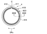
- FIG. 21 is a cross-sectional view taken along the line XXII-XXII of FIG.
- the EGR device is a device for returning a part of the exhaust gas discharged from the combustion chamber of the engine to the intake side of the engine.
- the EGR valve is a flow rate adjusting valve that adjusts the flow rate of the exhaust gas returned to the intake side of the engine.
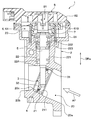
- the valve device 1 includes a housing 2, a valve body 3, a shaft 5, a valve drive unit 6, a return spring 7, a rotation angle detection unit 8, and the like. Note that FIG. 1 shows a valve device 1 when the valve body 3 fully closes the gas passage 20.
- Housing 2 is manufactured by, for example, aluminum die casting.
- the housing 2 is formed with a gas passage 20 through which exhaust gas flows.
- the gas passage 20 is a fluid passage through which the fluid passes.
- the exhaust gas flows through the gas passage 20 from the passage inlet 20a toward the passage outlet 20b.
- the gas passage 20 is provided with a bent portion 20c in which the flow direction of the exhaust gas changes between the passage inlet 20a side where the exhaust gas flows in and the passage outlet 20b side where the exhaust gas flows out. That is, the axial direction of the gas passage 20 on the passage inlet 20a side and the axial direction of the gas passage 20 on the passage outlet 20b side of the bent portion 20c intersect at a predetermined angle.
- a metal (for example, stainless steel) cylindrical nozzle 21 is press-fitted and fixed to the gas passage 20 on the side of the passage inlet 20a from the bent portion 20c.
- the cylindrical nozzle 21 forms a part of the gas passage 20 on the passage inlet 20a side.
- the housing 2 is formed with a bearing hole 22, a gear chamber 23, and the like.
- the bearing hole 22 is formed closer to the gas passage 20 than the gear chamber 23.
- the end of the bearing hole 22 on the gas passage 20 side communicates with the gas passage 20.
- the bearing hole 22 is formed in a direction orthogonal to the gas passage 20 on the passage outlet 20b side.
- the bearing hole 22 has a stepped shape in which the inner diameter gradually decreases as it approaches the gas passage 20.
- a first bearing 221 and a second bearing 222 for rotatably supporting the shaft 5 are fixed to the inner circumference of the bearing hole 22 by press fitting.
- the first bearing 221 is arranged in the bearing hole 22 at a position closer to the gas passage 20 than the second bearing 222.
- the first bearing 221 is composed of, for example, a slide bearing.
- the second bearing 222 is arranged in the bearing hole 22 at a position farther from the gas passage 20 than the first bearing 221.
- the second bearing 222 is composed of, for example, ball bearings.
- An oil seal 223 is provided between the first bearing 221 and the second bearing 222 to prevent oil or the like contained in the exhaust gas from flowing into the gear chamber 23.
- the bearing hole 22 is provided with a gas seal 224 that prevents foreign matter such as carbon deposits from entering at a position closer to the gas passage 20 than the first bearing 221.
- the gear chamber 23 is a space formed by partitioning the tubular portion 24 formed in the housing 2 in succession with the bearing hole 22 and the sensor cover 82 of the rotation angle detecting portion 8 covering the tubular portion.
- the gear chamber 23 houses a motor (not shown), a gear train 61, a return spring 7, and the like that constitute the valve drive unit 6.
- the shaft 5 is inserted through the bearing hole 22 so as to penetrate the bearing hole 22.
- one end of the shaft 5 in the axial direction DRa protrudes into the cylindrical nozzle 21 forming the gas passage 20 on the passage inlet 20a side.
- a valve body 3 is provided at one end of the shaft 5 in the axial direction DRa.
- the valve body 3 has a variable opening degree (that is, passage area) of the gas passage 20.
- the valve body 3 is configured as a butterfly valve having a substantially circular plate shape.
- the valve body 3 is arranged in a direction orthogonal to the axial direction of the cylindrical nozzle 21.
- the valve body 3 is integrally molded with the end portion of the shaft 5 in a state of being tilted by a predetermined angle with respect to the axial direction DRa of the shaft 5. The detailed configuration of the valve body 3 will be described later.
- the valve drive unit 6 is composed of a motor (not shown) that receives power supply and generates torque, and a gear train 61 that amplifies the drive torque of this motor and transmits it to the shaft 5.
- the motor is, for example, a DC motor, and is energized and controlled by an ECU (not shown).
- the gear train 61 is configured by, for example, meshing a plurality of gears.
- the gear train 61 is a deceleration composed of a pinion gear (not shown) attached to the output shaft of the motor, a valve gear 610 attached to the other end of the shaft 5, and an intermediate gear (not shown) that transmits the rotation of the pinion gear to the valve gear 610. It is a means.
- the return spring 7 urges the valve body 3 toward the valve closing direction.
- the return spring 7 is a coil spring and is coaxially arranged around the shaft 5. Specifically, the return spring 7 is assembled between the housing 2 and the valve gear 610 so that the valve body 3 is urged toward the valve closing direction.
- the rotation angle detection unit 8 is a non-contact position sensor that detects the opening degree of the valve body 3 based on the rotation angle of the shaft 5.
- the rotation angle detection unit 8 includes a detection unit 81 attached to the inner circumference of the valve gear 610.
- the detection unit 81 is composed of, for example, a magnetic sensor including a Hall element and a permanent magnet. For example, when the permanent magnet rotates together with the valve gear 610, the detection unit 81 outputs an electric signal proportional to the magnetic flux density penetrating the Hall element to an ECU (not shown).
- the sensor cover 82 is attached to the end surface of the housing 2 forming the gear chamber 23 via a sealing component (not shown).
- the sensor cover 82 is fixed to the housing 2 by a screw or the like (not shown) and airtightly covers the gear chamber 23.
- the ECU calculates the target opening degree of the valve body 3 according to the operating state of the engine grasped from the accelerator opening degree, the engine speed, and the like, and the actual opening degree of the valve body 3 detected by the detection unit 81 is the target opening.
- the power supply to the motor is feedback-controlled so as to match the degree.
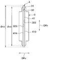
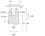
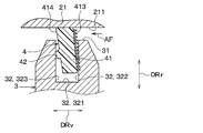
- the valve body 3 has an outer peripheral edge 31 facing the cylindrical nozzle 21 forming the gas passage 20. As shown in FIGS. 2 and 3, the valve body 3 has an outer peripheral groove 32 formed on the entire circumference of the outer peripheral edge 31. The outer peripheral groove 32 is recessed in a rectangular cross section.
- the outer peripheral groove 32 has a pair of groove side surfaces 322 and 323 that are connected to the groove bottom surface 321 and the groove bottom surface 321 that face the inner peripheral surface 211 that forms the gas passage 20 when the valve body 3 is fully closed, and that face each other. ..
- the inner peripheral surface 211 forming the gas passage 20 is a wall surface inside the cylindrical nozzle 21.
- the pair of groove side surfaces 322 and 323 are located on the downstream side of the gas passage 20 from the first groove side surface 322, which is one groove side surface, and the first groove side surface 322, which is the other groove side surface and when the valve body 3 is fully closed. It has a second groove side surface 323 to be located.
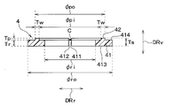
- valve diameter ⁇ vo which is the diameter at the outer peripheral edge 31, is larger than the valve groove diameter ⁇ vi, which is the diameter at the groove bottom surface 321.
- the outer peripheral groove 32 of the valve body 3 is set to a groove width Wg capable of accommodating the seal ring 4.
- the seal ring 4 is a resin member that seals between the inner peripheral surface 211 forming the gas passage 20 when the valve body 3 is fully closed and the outer peripheral edge 31 of the valve body 3. That is, the seal ring 4 creates a gap between the inner peripheral surface 211 of the cylindrical nozzle 21 and the outer peripheral edge 31 of the valve body 3 when the valve body 3 fully closes the gas passage 20 on the passage inlet 20a side. It has a sealing function to close it.
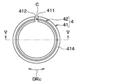
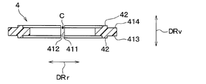
- the seal ring 4 has a ring main body 41 that is fitted into the outer peripheral groove 32.
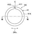
- the ring main body 41 has a C-shape.
- the ring main body 41 is formed with a predetermined gap C between the first peripheral end portion 411 and the second peripheral end portion 412 located at the end portions of the DRc in the circumferential direction.
- the first peripheral end portion 411 constitutes one peripheral end portion of the ring main body 41
- the second peripheral end 412 constitutes the other peripheral end of the ring main body 41.
- the ring main body 41 is composed of a square ring having a substantially rectangular cross section. That is, the ring main body 41 has a rectangular cross section.
- the cross-sectional shape having a quadrangular shape does not mean only a strict quadrangular shape, but also includes a quadrangular portion whose corners are cut into a straight line or an arc shape by chamfering or the like.
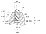
- the ring main body 41 has a ring outer diameter ⁇ ro larger than the valve diameter ⁇ vo of the outer peripheral edge 31 so that a part of the ring main body 41 protrudes to the outside of the outer peripheral groove 32.
- the ring main body 41 has an outer diameter portion 41X located outside the outer peripheral groove 32 and an inner diameter portion 41Y located inside the outer peripheral groove 32.
- the ring main body 41 has a pair of groove facing surfaces 413 and 414 that at least partially face the pair of groove side surfaces 322 and 322.
- the pair of groove facing surfaces 413 and 414 are the first groove facing surface 413, which is one groove facing surface, and the other groove facing surface, which is a gas passage more than the first groove facing surface 413 when the valve body 3 is fully closed. It has a second groove facing surface 414 located on the downstream side of 20.
- the first groove facing surface 413 faces the first groove side surface 322 of the outer peripheral groove 32
- the second groove facing surface 414 faces the second groove side surface 323 of the outer peripheral groove 32.
- the first groove facing surface 413 constitutes a pressure receiving surface that receives the pressure of the exhaust gas when the valve body 3 is fully closed.
- the first groove facing surface 413 is a flat surface extending along the radial DRr.
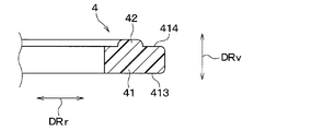
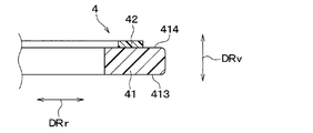
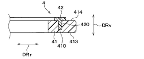
- the seal ring 4 is provided with a protrusion 42 protruding from the ring main body 41 toward the outer peripheral groove 32.
- the ring main body 41 and the protrusion 42 are configured as an integrally molded product that is integrally molded.
- the protrusion 42 has a quadrangular cross-sectional shape in the direction orthogonal to the circumferential DRc.
- the protrusion 42 has a width dimension orthogonal to the protrusion direction that is larger than a height dimension in the protrusion direction.
- the protrusion 42 is provided on the second groove facing surface 414 of the ring main body 41 so as to protrude toward the second groove side surface 323 forming the seal surface in the outer peripheral groove 32.
- the protrusion 42 is provided on the inner diameter portion 41Y of the ring main body 41 so as to face the second groove side surface 323.
- the outer diameter ⁇ po on the outer side of the radial DRr of the seal ring 4 is smaller than the valve diameter ⁇ vo of the valve body 3.
- the inner diameter ⁇ pi inside the radial DRr of the seal ring 4 is larger than the ring inner diameter ⁇ ri of the ring body 41.
- the ring body 41 is set so that the ring inner diameter ⁇ ri is smaller than the valve diameter ⁇ vo so as not to come out of the outer peripheral groove 32.
- the thickness Tp of the protrusion 42 in the axial direction DRv is smaller than the thickness Tr of the ring main body 41.
- the protrusion 42 has a width Tw of the radial DRr of the seal ring 4 larger than the thickness Tp of the axial DRv so that a contact area when contacting the second groove side surface 323 can be secured to some extent. There is.
- the protrusion 42 is provided along the circumferential direction DRc so as to be continuously continuous from the first peripheral end portion 411 to the second peripheral end portion 412 of the ring main body portion 41. That is, the protrusion 42 is provided over the entire area of the ring main body 41 in the circumferential direction DRc.
- the valve device 1 may be used in a cold region, and the temperature of the gas passage 20 may change from an extremely low temperature to an extremely high temperature. Further, the materials of the valve body 3 and the seal ring 4 may be different. Therefore, a clearance is provided between the valve body 3 and the seal ring 4 in consideration of the difference in linear expansion. Specifically, in the seal ring 4, the thickness Ts in the axial direction DRv is smaller than the groove width Wg of the outer peripheral groove 32. In the seal ring 4, the ring inner diameter ⁇ ri is larger than the valve groove diameter ⁇ vi of the outer peripheral groove 32.
- valve device 1 When increasing the flow rate of the exhaust gas returned to the intake side of the engine, the valve device 1 rotationally displaces the valve body 3 so that the opening degree of the gas passage 20 increases. Further, when the flow rate of the exhaust gas returned to the intake side of the engine is reduced, the valve device 1 rotationally displaces the valve body 3 so that the opening degree of the gas passage 20 is reduced. Then, when the exhaust gas is not returned to the intake side of the engine, the valve device 1 rotationally displaces the valve body 3 at a position where the gas passage 20 is closed, as shown in FIG.
- FIG. 7 shows a seal ring CE as a comparative example of the seal ring 4 of the present embodiment.
- the seal ring CE of the comparative example is different in that the surface facing the outer peripheral groove 32 is formed flat, that is, there is nothing corresponding to the protrusion 42 provided on the seal ring 4 of the present embodiment. ing.
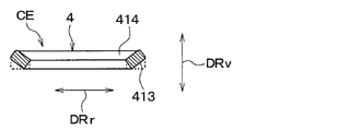
- the flatness of the seal ring CE may deteriorate due to sink marks or deformation during resin molding.
- the seal ring CE may have a shape in which the inner diameter side and the outer diameter side are displaced in the axial direction DRv of the seal ring CE due to sink marks or deformation during resin molding. is there.
- the water contained in the exhaust gas is condensed by an EGR cooler (not shown). This generation of condensed water is not preferable because it causes corrosion of the EGR cooler and liquid compression in the turbocharger upstream of the engine.
- the seal ring 4 of the present embodiment has a protrusion 42 protruding toward the second groove side surface 323 of the outer peripheral groove 32. That is, the protrusion 42 is provided on the second groove facing surface 414 of the ring main body 41 with respect to the second groove side surface 323 formed on the seal surface in the outer peripheral groove 32.
- the protrusion 42 makes it easier for the seal ring 4 to come into contact with the outer peripheral groove 32, so that it is possible to suppress a decrease in contact surface pressure. It becomes.
- seal ring 4 and the valve device 1 of the present embodiment described above it is easy to secure the surface pressure at the time of contact between the outer peripheral groove 32 of the valve body 3 and the seal ring 4, so that deterioration of the seal property can be suppressed. Can be done.
- the protrusion 42 is provided in the inner diameter portion 41Y located inside the outer peripheral groove 32 in the ring main body 41. According to this, as compared with the case where the protrusion 42 is provided on the outer diameter portion 41X, the seal ring 4 is more likely to come into contact with the outer peripheral groove 32, so that it is possible to sufficiently suppress the decrease in the surface pressure at the time of contact. In addition, since the seal ring 4 is easily brought into contact with the outer peripheral groove 32, it is possible to prevent the seal ring 4 from coming out of the outer peripheral groove 32.
- the protrusion 42 is provided on the second groove facing surface 414 of the ring main body 41 with respect to the second groove side surface 323 formed on the seal surface in the outer peripheral groove 32. According to this, the protrusion 42 is pressed against the second groove side surface 323 of the outer peripheral groove 32 by the exhaust gas flowing through the gas passage 20 when the valve body 3 is fully closed. At this time, since the pressure at the time of contact is concentrated on the protrusion 42, it is possible to sufficiently secure the surface pressure at the time of contact between the outer peripheral groove 32 of the valve body 3 and the seal ring 4.
- the protrusion 42 is provided along the circumferential DRc so as to be continuously continuous from the first peripheral end 411 located at the end of the circumferential DRc in the ring main body 41 to the second peripheral end 412. ing. If the protrusion 42 is provided from the first peripheral end portion 411 to the second peripheral end portion 412 of the ring main body 41 in this way, a gap between the seal ring 4 and the outer peripheral groove 32 is unlikely to occur. The deterioration of the sealing property can be sufficiently suppressed.
- the protrusion 42 has a quadrangular cross-sectional shape in the direction orthogonal to the circumferential DRc. In this way, when the cross-sectional shape of the protrusion 42 is quadrangular, the protrusion 42 makes it easier for the seal ring 4 to come into contact with the outer peripheral groove 32, so that it is possible to suppress a decrease in surface pressure at the time of contact.
- the seal ring 4 of the first embodiment described above is provided with a protrusion 42 on the second groove facing surface 414 of the ring main body 41, but the present invention is not limited to this.
- the seal ring 4 may be provided with a protrusion 42 on each of the first groove facing surface 413 and the second groove facing surface 414.
- the seal ring 4 may be provided with a protrusion 42 on the first groove facing surface 413, for example.
- the protrusion 42 of the first embodiment described above has a rectangular cross-sectional shape, but is not limited thereto. As shown in FIG. 12, the protruding portion 42 may have its corners cut into an arc shape by chamfering or the like. The corners of the protrusion 42 may be cut in a straight line by chamfering or the like.
- the ring main body portion 41 and the protrusion portion 42 are integrally molded, but the present invention is not limited to this.
- the ring main body 41 and the protrusion 42 which are separately formed from each other, may be integrally joined by an adhesive.
- the seal ring 4 is formed separately from the ring main body 41 and the protrusion 42, and is integrally formed by fitting the projecting piece 420 of the protrusion 42 into the fitting groove 410 provided in the ring main body 41. It may be connected.
- the seal ring 4 may have an integral structure in which a protrusion provided in the ring main body 41 is fitted into a fitting groove 410 provided in the protrusion 42.
- the various dimensions of the protrusion 42 are not limited to those described in the first embodiment.
- the outer diameter ⁇ po on the outer side of the radial DRr of the seal ring 4 may be larger than the valve diameter ⁇ vo of the valve body 3. That is, the protrusion 42 may be provided so as to extend over the inner diameter portion 41Y and the outer diameter portion 41X of the ring main body 41.
- the protrusion 42 may have a thickness Tp of DRv in the axial direction larger than the thickness Tr of the ring body 41. Further, the protrusion 42 may have a width Tw of the radial DRr smaller than the thickness Tp of the axial DRv.
- the seal ring 4 is provided along the circumferential direction DRc so that the protrusion 42 is continuously connected from the first peripheral end portion 411 to the second peripheral end portion 412 of the ring main body portion 41.
- the seal ring 4 may have a portion where the protrusion 42 is not provided other than the gap C between the first peripheral end portion 411 and the second peripheral end portion 412 of the ring main body 41.
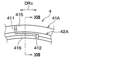
- the total length of the circumferential DRc of the ring main body 41A is larger than the circumferential length formed by the ring main body 41A, and the end sides of the circumferential DRc overlap each other. It is configured. That is, in the ring main body portion 41A, the first peripheral end side portion 415 including the first peripheral end portion 411 and the second peripheral end side portion 416 including the second peripheral end portion 412 overlap in the direction intersecting the circumferential DRc. It is configured as follows.
- the first peripheral end side portion 415 and the second peripheral end side portion 416 are configured to be square rings having a substantially rectangular cross-sectional shape when they are overlapped with each other.
- the second peripheral end side portion 416 has an L-shaped cross section. That is, the second peripheral end side portion 416 has a shape in which the corner portion located outside the radial DRr is removed from the portion facing the first groove side surface 322.
- the first peripheral end side portion 415 has a shape corresponding to the removed corner portion in the second peripheral end side portion 416. That is, the first peripheral end side portion 415 has a rectangular cross-sectional shape.
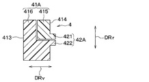
- the ring main body 41A is configured such that the first peripheral end side portion 415 and the second peripheral end side portion 416 overlap each other in the axial direction DRv and the radial direction DRr intersecting the circumferential DRc.
- the protrusion 42A is provided on each of the first peripheral end side portion 415 and the second peripheral end side portion 416. That is, the protrusion 42A is composed of a first convex portion 421 provided on the first peripheral end side portion 415 and a second convex portion 422 provided on the second peripheral end side portion 416. The protrusion 42A is provided over the entire circumferential direction DRc of the ring main body 41A so as to form an annular shape.
- the seal ring 4 and the valve device 1 of the present embodiment can obtain the same action and effect as those of the first embodiment from the same configuration or the equivalent configuration as that of the first embodiment.
- the seal ring 4 of the present embodiment is configured so that the first peripheral end side portion 415 and the second peripheral end side portion 416 of the ring main body portion 41A overlap each other in the direction intersecting the circumferential DRc.
- the protrusion 42A is provided over the entire circumferential direction DRc of the ring main body 41A so as to form an annular shape.
- the ring main body 41A of the second embodiment described above is configured such that the first peripheral end side portion 415 and the second peripheral end side portion 416 overlap each other in the axial direction DRv and the radial direction DRr. Not limited.
- the ring main body portion 41A may be configured such that the first peripheral end side portion 415 and the second peripheral end side portion 416 overlap one of the axial DRv and the radial DRr.
- the cross-sectional shape of the second peripheral end side portion 416 is L-shaped, and the cross-sectional shape of the first peripheral end side portion 415 is square, but the present invention is not limited to this.
- the cross-sectional shape of the first peripheral end side portion 415 is L-shaped
- the cross-sectional shape of the second peripheral end side portion 416 is square
- the first peripheral end side portion 415 and The cross-sectional shape of each of the second peripheral end side portions 416 may be L-shaped.
- the protrusion 42 is provided along the entire circumferential DRc of the ring main body 41A, but the seal ring 4 is not limited to this.
- the seal ring 4 may have a portion where the protrusion 42 is not provided at the position of the ring main body 41A in the circumferential direction DRc.
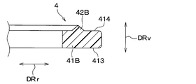
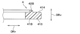
- the protrusion 42B has a tapered shape that tapers toward the tip. That is, the protrusion 42B has a shape in which the cross-sectional shape in the direction orthogonal to the circumferential direction DRc becomes smaller toward the tip.
- the protrusion 42B has a triangular cross-sectional shape in the direction orthogonal to the circumferential DRc.
- the width dimension of the protrusion 42B near the boundary with the ring body 41B is larger than the height dimension in the protrusion direction.
- the seal ring 4 and the valve device 1 of the present embodiment can obtain the same action and effect as those of the first embodiment from the same configuration or the equivalent configuration as that of the first embodiment.
- the seal ring 4 of the present embodiment has a tapered shape in which the protrusion 42B tapers toward the tip. In this way, if the protrusion 42B has a tapered shape, the contact area between the protrusion 42B and the outer peripheral groove 32 becomes smaller, and pressure tends to be concentrated on the local portion. Therefore, the protrusion 42B and the outer peripheral groove 32 The surface pressure at the time of contact with the seal ring 4 can be sufficiently increased.
- the width dimension near the boundary with the ring body portion 41B is larger than the height dimension in the protrusion direction, but the width dimension is not limited to this, and the width dimension is the height in the protrusion direction. It may be less than or equal to the size.
- the protrusion 42B has a triangular cross-sectional shape in the direction orthogonal to the circumferential DRc, but is not limited to this. As shown in FIG. 19, the protrusion 42B may have a trapezoidal shape in which the bottom side on the ring body 41B side is longer than the bottom side on the tip side in the cross-sectional shape in the direction orthogonal to the circumferential direction DRc.
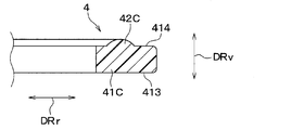
- the protrusion 42C has a cross-sectional shape including an arc in the direction orthogonal to the circumferential DRc.
- the protrusion 42C is raised in an arc shape toward the outer peripheral groove 32.
- the width dimension of the protrusion 42C near the boundary with the ring body 41C is larger than the height dimension in the protrusion direction.
- the seal ring 4 and the valve device 1 of the present embodiment can obtain the same action and effect as those of the first embodiment from the same configuration or the equivalent configuration as that of the first embodiment.
- the cross-sectional shape of the protrusion 42C is a shape including an arc.
- the cross-sectional shape of the protrusion 42C is a shape including an arc
- the outer shape of the portion in contact with the groove 32 is unlikely to change. Therefore, the contact state between the protrusion 42C and the outer peripheral groove 32 can be maintained, and the deterioration of the sealing property due to the deformation of the seal ring 4 can be sufficiently suppressed.
- the cross-sectional shape of the protrusion 42C may be not only an arc but also a flat portion. Further, the protrusion 42C may have a curved surface shape formed by combining arcs having different curvatures.
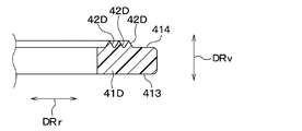
- the ring main body 41D is provided with a plurality of protrusions 42D arranged side by side in a direction intersecting the circumferential DRc.
- the plurality of protrusions 42D are formed at different positions in the radial DRr, and each of them extends parallel to the circumferential DRc.
- the plurality of protrusions 42D have a tapered shape that tapers toward the tip so as not to interfere with each other. Specifically, the plurality of protrusions 42D have a triangular cross-sectional shape in the direction orthogonal to the circumferential DRc.
- the seal ring 4 and the valve device 1 of the present embodiment can obtain the same action and effect as those of the first embodiment from the same configuration or the equivalent configuration as that of the first embodiment.
- the seal ring 4 of the present embodiment is provided on the ring main body 41D in a direction in which a plurality of protrusions 42D intersect with the circumferential DRc. According to this, the contact area between the seal ring 4 and the outer peripheral groove 32 can be expanded, and the deterioration of the sealing property due to the deformation of the ring main body 41D can be sufficiently suppressed.
- the ring main body 41D of the fifth embodiment described above has the same shape as the ring main body 41 described in the first embodiment, but is not limited to this, and is not limited to the ring main body 41A described in the second embodiment. It may have the same shape.
- the plurality of protrusions 42D have a triangular cross-sectional shape in the direction orthogonal to the circumferential direction DRc, but the cross-sectional shape is not limited to this, and the cross-sectional shape may be a shape including a quadrangular shape or an arc. Further, the plurality of protrusions 42D may have a cross-sectional shape of some of the protrusions 42D different from that of the other protrusions 42D.
- the protrusion 42 is provided at the inner diameter portion 41Y of the ring main body 41, but the seal ring 4 is not limited to this. As for the seal ring 4, for example, a part of the protrusion 42 may be provided on the outer diameter portion 41X of the ring main body 41.
- the protrusion 42 is provided on the second groove facing surface 414 of the ring main body 41, but the seal ring 4 is not limited to this.
- the seal ring 4 may be provided on, for example, the first groove facing surface 413 of the ring main body 41.
- the seal ring 4 having the first peripheral end portion 411 and the second peripheral end portion 412 has been exemplified, but the seal ring 4 is not limited thereto.
- the seal ring 4 may have an O-shape, for example, as long as the shape can be expanded in the radial direction DRr.
- a protrusion 42 is provided on the first groove facing surface 413 and the second groove facing surface 414 of the ring main body 41, but the seal ring 4 is not limited to this.
- the seal ring 4 may be provided with a protrusion 42 on a surface other than the first groove facing surface 413 and the second groove facing surface 414 of the ring main body 41, for example.
- valve device 1 including the seal ring 4 of the present disclosure is applied to the EGR valve, but the application target is not limited to the EGR valve.
- the valve device 1 including the seal ring 4 of the present disclosure is applicable to various valves other than the EGR valve.
- the seal ring extends in the circumferential direction of the ring body portion fitted in the outer peripheral groove of the valve body and the ring body portion and the ring body portion. It is provided with a protrusion that protrudes from the outer peripheral groove toward the outer peripheral groove.
- the outer peripheral groove has a groove bottom surface facing the inner peripheral surface and a pair of groove side surfaces facing each other while being connected to the groove bottom surface when the valve body is fully closed.
- the ring main body has a pair of groove facing surfaces that at least partially face the pair of groove side surfaces.
- the protrusions are provided on at least one of the pair of groove facing surfaces.
- the ring main body portion has an outer diameter portion located outside the outer peripheral groove and an inner diameter portion located inside the outer peripheral groove when it is fitted into the outer peripheral groove.
- the protrusion is provided on the inner diameter portion.
- the seal ring is more likely to come into contact with the outer peripheral groove than when the protrusion is provided on the outer diameter, so that the surface pressure at the time of contact can be reduced. It becomes possible to suppress it sufficiently.
- the seal ring is easily brought into contact with the outer peripheral groove, so that the seal ring is prevented from coming out of the outer peripheral groove.
- the pair of groove facing surfaces are the first groove facing surface, which is one groove facing surface, and the other groove facing surface, which is larger than the first groove facing surface when the valve body is fully closed. It has a second groove facing surface located on the downstream side of the fluid passage. The protrusion is provided at least on the surface facing the second groove.
- the protrusion is pressed against the second groove facing surface of the outer peripheral groove by the fluid flowing through the fluid passage when the valve body is fully closed. At this time, since the pressure at the time of contact is concentrated on the protrusion, it is possible to sufficiently secure the surface pressure at the time of contact between the outer peripheral groove of the valve body and the seal ring.
- the ring main body has a C-shape.
- the protrusions are provided along the circumferential direction so as to be continuously continuous from one of the pair of peripheral ends located at the peripheral ends of the ring main body to the other.
- the ring main body portion is configured such that the portions including the pair of peripheral end portions located at the peripheral end portions of the ring main body portion overlap each other in the direction in which they intersect in the circumferential direction. ..
- the protrusions are provided over the entire circumferential direction of the ring body so as to form an annular shape.
- the protrusion has a quadrangular cross-sectional shape in the direction orthogonal to the circumferential direction. As described above, even if the cross-sectional shape of the protrusion is square, the protrusion makes it easier for the seal ring to come into contact with the outer peripheral groove, so that it is possible to suppress a decrease in surface pressure at the time of contact.
- the protrusion has a tapered shape that tapers toward the tip. In this way, if the protrusion has a tapered shape, the contact area between the protrusion and the outer peripheral groove becomes smaller, so that the surface pressure at the time of contact between the outer peripheral groove of the valve body and the seal ring can be sufficiently increased. it can.
- the protrusion has a shape in which the cross-sectional shape in the direction orthogonal to the circumferential direction includes an arc.
- the cross-sectional shape of the protrusion is a shape that includes an arc
- the outer shape of the portion of the protrusion that contacts the outer peripheral groove is unlikely to change even if the seal ring is twisted or tilted.
- the contact state between the protrusion and the outer peripheral groove can be maintained. As a result, it is possible to sufficiently suppress the deterioration of the sealing property due to the deformation of the sealing ring.
- the ring main body is provided with a plurality of protrusions arranged side by side in the circumferential direction. According to this, the contact area between the seal ring and the outer peripheral groove can be expanded, and the deterioration of the sealing property due to the deformation of the ring main body can be sufficiently suppressed.
- the valve device includes a valve body that changes the opening degree of the fluid passage through which the fluid passes, an inner peripheral surface that forms the fluid passage when the valve body is fully closed, and an outer peripheral edge of the valve body. It is equipped with a resin seal ring that seals between them.
- the seal ring includes a ring main body that is fitted into the outer peripheral groove formed on the outer peripheral edge, and a protrusion that is provided on the ring main body and extends in the circumferential direction of the ring main body and protrudes from the ring main body toward the outer peripheral groove.
- the outer peripheral groove has a groove bottom surface facing the inner peripheral surface and a pair of groove side surfaces facing each other while being connected to the groove bottom surface when the valve body is fully closed.
- the ring main body has a pair of groove facing surfaces that at least partially face the pair of groove side surfaces.
- the protrusions are provided on at least one of the pair of groove facing surfaces.
Abstract
A seal ring (4) is made from resin, is applied to a valve body (3) that varies the degree of opening of a fluid passage (20) through which a fluid passes, and forms a seal between an inner circumferential surface (211) and an outer circumferential edge (31) of the valve body which form the fluid passage when the valve body is fully closed. The seal ring is provided with a ring body part (41), which is fitted into an outer circumferential groove (32) formed in the outer circumferential edge, and a protruding part (42), which is provided on the ring body part, extends in the circumferential direction of the ring body part, and protrudes from the ring body part toward the outer circumferential groove. The outer circumferential groove has a groove bottom surface (321) that opposes the inner circumferential surface when the valve body is fully closed, and a pair of groove side surfaces (322, 323) continuous with the groove bottom surface and opposing one another. The ring body part has a pair of groove-opposing surfaces (413, 414) at least a portion of which faces the pair of groove side surfaces. The protruding part is provided on at least one of the pair of groove-opposing surfaces.
Description
本出願は、2019年8月1日に出願された日本特許出願番号2019-142393号に基づくもので、ここにその記載内容が参照により組み入れられる。
This application is based on Japanese Patent Application No. 2019-142393 filed on August 1, 2019, the contents of which are incorporated herein by reference.
本開示は、シールリング、当該シールリングを備える弁装置に関する。
The present disclosure relates to a seal ring and a valve device provided with the seal ring.
従来、気体の流れる通路の開度を弁体の回動により可変する弁装置が知られている(例えば、特許文献1参照)。この特許文献1には、弁体の外周を樹脂製であって断面が平板形状のシールリングで覆うことで、寸法公差を緩和しながら全閉時の気体漏れを抑制可能であることが開示されている。
Conventionally, a valve device that changes the opening degree of a passage through which a gas flows by rotating a valve body is known (see, for example, Patent Document 1). Patent Document 1 discloses that by covering the outer periphery of a valve body with a seal ring made of resin and having a flat cross section, it is possible to suppress gas leakage when fully closed while relaxing dimensional tolerances. ing.
本発明者らは、樹脂製のシールリングのシール性について鋭意検討した。この検討によれば、樹脂製のシールリングでは、例えば、樹脂成型時のヒケや変形によってシールリングの平面度が悪化する虞があることが判った。シールリングの平面度が悪化すると、接触時の面圧(すなわち、接触面圧)が減少してシール性が低下してしまう。
本開示は、シール性の低下を抑制可能なシールリングおよび弁装置を提供することを目的とする。 The present inventors have diligently studied the sealing property of the resin seal ring. According to this study, it was found that in the resin seal ring, for example, the flatness of the seal ring may be deteriorated due to sink marks or deformation during resin molding. When the flatness of the seal ring deteriorates, the surface pressure at the time of contact (that is, the contact surface pressure) decreases, and the sealing property deteriorates.
It is an object of the present disclosure to provide a sealing ring and a valve device capable of suppressing a decrease in sealing property.
本開示の1つの観点によれば、
シールリングは、
流体が通過する流体通路の開度を可変する弁体に適用され、弁体の全閉時に流体通路を形成する内周面と弁体の外周縁との間をシールする樹脂製のものであって、
外周縁に形成された外周溝に嵌め込まれるリング本体部と、
リング本体部に設けられてリング本体部の周方向に延びるとともにリング本体部から外周溝に向けて突き出る突起部と、を備え、
外周溝は、弁体の全閉時に内周面に対向する溝底面および溝底面に連なるとともに互いに対向する一対の溝側面を有しており、
リング本体部は、一対の溝側面に対して少なくとも一部が対向する一対の溝対向面を有しており、
突起部は、一対の溝対向面の少なくとも一方に設けられている。 According to one aspect of the disclosure,
The seal ring is
It is applied to a valve body that changes the opening of the fluid passage through which the fluid passes, and is made of resin that seals between the inner peripheral surface that forms the fluid passage and the outer peripheral edge of the valve body when the valve body is fully closed. hand,
The ring body that fits into the outer peripheral groove formed on the outer peripheral edge,
The ring body is provided with a protrusion that extends in the circumferential direction of the ring body and protrudes from the ring body toward the outer peripheral groove.
The outer peripheral groove has a groove bottom surface facing the inner peripheral surface and a pair of groove side surfaces facing each other while being connected to the groove bottom surface when the valve body is fully closed.
The ring main body has a pair of groove facing surfaces at least partially facing the pair of groove side surfaces.
The protrusions are provided on at least one of the pair of groove facing surfaces.
このように、外周溝においてシール面を構成する溝側面に対向する溝対向面に突起部を設ける構成とすれば、リング本体部の平面度が悪化しても、突起部によってシールリングが外周溝に接し易くなるので接触時の面圧の減少を抑えることが可能となる。したがって、本開示のシールリングによれば、弁体の外周溝とシールリングとの接触時の面圧を確保し易いので、シール性の低下を抑制することができる。
In this way, if a protrusion is provided on the groove facing surface facing the groove side surface forming the seal surface in the outer peripheral groove, even if the flatness of the ring main body deteriorates, the seal ring is formed by the protrusion to form the outer groove. Since it becomes easy to come into contact with the water, it is possible to suppress a decrease in the surface pressure at the time of contact. Therefore, according to the seal ring of the present disclosure, it is easy to secure the surface pressure at the time of contact between the outer peripheral groove of the valve body and the seal ring, so that deterioration of the seal property can be suppressed.
ここで、平面度は、平面の滑らかさ(すなわち、均一性)を示すもので、平面形体の幾何学的に正しい平面からの狂いの大きさである。
Here, the flatness indicates the smoothness (that is, uniformity) of the plane, and is the magnitude of the deviation from the geometrically correct plane of the plane feature.
本開示の別の観点によれば、
弁装置は、
流体が通過する流体通路の開度を可変する弁体と、
弁体の全閉時に流体通路を形成する内周面と弁体の外周縁との間をシールする樹脂製のシールリングと、を備え、
シールリングは、
外周縁に形成された外周溝に嵌め込まれるリング本体部と、
リング本体部に設けられてリング本体部の周方向に延びるとともにリング本体部から外周溝に向けて突き出る突起部と、を備え、
外周溝は、弁体の全閉時に内周面に対向する溝底面および溝底面に連なるとともに互いに対向する一対の溝側面を有しており、
リング本体部は、一対の溝側面に対して少なくとも一部が対向する一対の溝対向面を有しており、
突起部は、一対の溝対向面の少なくとも一方に設けられている。 According to another aspect of the disclosure,
The valve device
A valve body that changes the opening of the fluid passage through which the fluid passes,
It is provided with a resin seal ring that seals between the inner peripheral surface that forms a fluid passage when the valve body is fully closed and the outer peripheral edge of the valve body.
The seal ring is
The ring body that fits into the outer peripheral groove formed on the outer peripheral edge,
The ring body is provided with a protrusion that extends in the circumferential direction of the ring body and protrudes from the ring body toward the outer peripheral groove.
The outer peripheral groove has a groove bottom surface facing the inner peripheral surface and a pair of groove side surfaces facing each other while being connected to the groove bottom surface when the valve body is fully closed.
The ring main body has a pair of groove facing surfaces at least partially facing the pair of groove side surfaces.
The protrusions are provided on at least one of the pair of groove facing surfaces.
このようにリング本体部に対して外周溝に向けて突き出る突起部を設ける構成とすれば、リング本体部の平面度が悪化しても、突起部によってシールリングが外周溝に接し易くなるので接触時の面圧の減少を抑えることが可能となる。したがって、本開示の弁装置によれば、弁体の外周溝とシールリングとの接触時の面圧を確保し易いので、シール性の低下を抑制することができる。
If the ring body is provided with a protrusion that protrudes toward the outer peripheral groove in this way, even if the flatness of the ring body deteriorates, the protrusion makes it easier for the seal ring to come into contact with the outer groove. It is possible to suppress the decrease in surface pressure at the time. Therefore, according to the valve device of the present disclosure, it is easy to secure the surface pressure at the time of contact between the outer peripheral groove of the valve body and the seal ring, so that deterioration of the sealing property can be suppressed.
なお、各構成要素等に付された括弧付きの参照符号は、その構成要素等と後述する実施形態に記載の具体的な構成要素等との対応関係の一例を示すものである。
Note that the reference reference numerals in parentheses attached to each component or the like indicate an example of the correspondence between the component or the like and the specific component or the like described in the embodiment described later.
以下、本開示の実施形態について図面を参照して説明する。なお、以下の実施形態において、先行する実施形態で説明した事項と同一もしくは均等である部分には、同一の参照符号を付し、その説明を省略する場合がある。また、実施形態において、構成要素の一部だけを説明している場合、構成要素の他の部分に関しては、先行する実施形態において説明した構成要素を適用することができる。以下の実施形態は、特に組み合わせに支障が生じない範囲であれば、特に明示していない場合であっても、各実施形態同士を部分的に組み合わせることができる。
Hereinafter, embodiments of the present disclosure will be described with reference to the drawings. In the following embodiments, the same reference numerals may be assigned to parts that are the same as or equivalent to those described in the preceding embodiments, and the description thereof may be omitted. Further, when only a part of the component is described in the embodiment, the component described in the preceding embodiment can be applied to the other part of the component. The following embodiments can be partially combined with each other as long as the combination does not cause any trouble, even if not explicitly stated.
(第1実施形態)
本実施形態について、図1~図10を参照して説明する。本実施形態は、本開示のシールリング4を含む弁装置1を、EGR装置のEGRバルブに適用した例について説明する。なお、EGRは、「Exhaust Gas Recirculation」の略称である。 (First Embodiment)
This embodiment will be described with reference to FIGS. 1 to 10. This embodiment describes an example in which thevalve device 1 including the seal ring 4 of the present disclosure is applied to the EGR valve of the EGR device. EGR is an abbreviation for "Exhaust Gas Recirculation".
本実施形態について、図1~図10を参照して説明する。本実施形態は、本開示のシールリング4を含む弁装置1を、EGR装置のEGRバルブに適用した例について説明する。なお、EGRは、「Exhaust Gas Recirculation」の略称である。 (First Embodiment)
This embodiment will be described with reference to FIGS. 1 to 10. This embodiment describes an example in which the
EGR装置は、エンジンの燃焼室より排出される排出ガスの一部をエンジンの吸気側に戻すための装置である。EGRバルブは、エンジンの吸気側に戻す排出ガスの流量を調整する流量調整弁である。
The EGR device is a device for returning a part of the exhaust gas discharged from the combustion chamber of the engine to the intake side of the engine. The EGR valve is a flow rate adjusting valve that adjusts the flow rate of the exhaust gas returned to the intake side of the engine.
図1に示すように、弁装置1は、ハウジング2と、弁体3と、シャフト5と、弁駆動部6と、リターンスプリング7と、回転角検出部8等を備える。なお、図1には、弁体3がガス通路20を全閉する全閉時の弁装置1が図示されている。
As shown in FIG. 1, the valve device 1 includes a housing 2, a valve body 3, a shaft 5, a valve drive unit 6, a return spring 7, a rotation angle detection unit 8, and the like. Note that FIG. 1 shows a valve device 1 when the valve body 3 fully closes the gas passage 20.
ハウジング2は、例えば、アルミダイカストにより製造される。ハウジング2は、排出ガスが流れるガス通路20が形成されている。ガス通路20は、流体が通過する流体通路である。排出ガスは、図1の矢印AFに示すように、通路入口20aから通路出口20bに向かってガス通路20を流れる。ガス通路20は、排出ガスが流入する通路入口20a側と排出ガスが流出する通路出口20b側との間に排出ガスの流れ方向が変化する屈曲部20cが設けられている。つまり、屈曲部20cより通路入口20a側のガス通路20の軸心方向と通路出口20b側のガス通路20の軸心方向とが所定の角度で交差している。屈曲部20cより通路入口20a側のガス通路20には、金属製(例えばステンレス製)の円筒ノズル21が圧入固定される。この円筒ノズル21は、通路入口20a側のガス通路20の一部を構成する。
Housing 2 is manufactured by, for example, aluminum die casting. The housing 2 is formed with a gas passage 20 through which exhaust gas flows. The gas passage 20 is a fluid passage through which the fluid passes. As shown by the arrow AF in FIG. 1, the exhaust gas flows through the gas passage 20 from the passage inlet 20a toward the passage outlet 20b. The gas passage 20 is provided with a bent portion 20c in which the flow direction of the exhaust gas changes between the passage inlet 20a side where the exhaust gas flows in and the passage outlet 20b side where the exhaust gas flows out. That is, the axial direction of the gas passage 20 on the passage inlet 20a side and the axial direction of the gas passage 20 on the passage outlet 20b side of the bent portion 20c intersect at a predetermined angle. A metal (for example, stainless steel) cylindrical nozzle 21 is press-fitted and fixed to the gas passage 20 on the side of the passage inlet 20a from the bent portion 20c. The cylindrical nozzle 21 forms a part of the gas passage 20 on the passage inlet 20a side.
ハウジング2は、ガス通路20の他に、軸受孔22およびギヤ室23等が形成されている。軸受孔22は、ギヤ室23よりもガス通路20の近くに形成されている。軸受孔22は、ガス通路20側の端部がガス通路20に連通している。軸受孔22は、通路出口20b側のガス通路20と直交する方向に形成されている。軸受孔22は、ガス通路20に近づくともなって内径が段階的に小さくなる段付き形状になっている。軸受孔22の内周には、シャフト5を回転自在に支持するための第1軸受221および第2軸受222が圧入により固定されている。
In addition to the gas passage 20, the housing 2 is formed with a bearing hole 22, a gear chamber 23, and the like. The bearing hole 22 is formed closer to the gas passage 20 than the gear chamber 23. The end of the bearing hole 22 on the gas passage 20 side communicates with the gas passage 20. The bearing hole 22 is formed in a direction orthogonal to the gas passage 20 on the passage outlet 20b side. The bearing hole 22 has a stepped shape in which the inner diameter gradually decreases as it approaches the gas passage 20. A first bearing 221 and a second bearing 222 for rotatably supporting the shaft 5 are fixed to the inner circumference of the bearing hole 22 by press fitting.
第1軸受221は、軸受孔22において第2軸受222よりもガス通路20に近い位置に配置されている。第1軸受221は、例えば、すべり軸受で構成されている。また、第2軸受222は、軸受孔22において第1軸受221よりもガス通路20から離れた位置に配置されている。第2軸受222は、例えば、玉軸受で構成されている。
The first bearing 221 is arranged in the bearing hole 22 at a position closer to the gas passage 20 than the second bearing 222. The first bearing 221 is composed of, for example, a slide bearing. Further, the second bearing 222 is arranged in the bearing hole 22 at a position farther from the gas passage 20 than the first bearing 221. The second bearing 222 is composed of, for example, ball bearings.
第1軸受221と第2軸受222との間には、排出ガスに含まれるオイル等がギヤ室23へ流入すること防止するオイルシール223が配設されている。軸受孔22には、第1軸受221よりもガス通路20に近い位置に、カーボンデポジット等の異物の侵入を防止するガスシール224が配設されている。
An oil seal 223 is provided between the first bearing 221 and the second bearing 222 to prevent oil or the like contained in the exhaust gas from flowing into the gear chamber 23. The bearing hole 22 is provided with a gas seal 224 that prevents foreign matter such as carbon deposits from entering at a position closer to the gas passage 20 than the first bearing 221.
ギヤ室23は、ハウジング2において軸受孔22に連なって形成される筒状部24と当該筒状部を覆う回転角検出部8のセンサカバー82とで区画形成される空間である。ギヤ室23には、弁駆動部6を構成する図示しないモータ、ギヤトレイン61、リターンスプリング7等が収容される。
The gear chamber 23 is a space formed by partitioning the tubular portion 24 formed in the housing 2 in succession with the bearing hole 22 and the sensor cover 82 of the rotation angle detecting portion 8 covering the tubular portion. The gear chamber 23 houses a motor (not shown), a gear train 61, a return spring 7, and the like that constitute the valve drive unit 6.
シャフト5は、軸受孔22を貫通するように軸受孔22に挿通されている。シャフト5は、シャフト5の軸心方向DRaの一方の端部が、通路入口20a側のガス通路20を形成する円筒ノズル21の内部へ突き出ている。シャフト5の軸心方向DRaの一方の端部には、弁体3が設けられている。
The shaft 5 is inserted through the bearing hole 22 so as to penetrate the bearing hole 22. In the shaft 5, one end of the shaft 5 in the axial direction DRa protrudes into the cylindrical nozzle 21 forming the gas passage 20 on the passage inlet 20a side. A valve body 3 is provided at one end of the shaft 5 in the axial direction DRa.
弁体3は、ガス通路20の開度(すなわち、通路面積)を可変するものである。弁体3は、略円形板状のバタフライ弁として構成されている。弁体3は、円筒ノズル21の軸心方向と直交する向きに配置されている。弁体3は、シャフト5の軸心方向DRaに対し所定の角度だけ傾いた状態でシャフト5の端部に一体成形されている。弁体3の詳細な構成は後述する。
The valve body 3 has a variable opening degree (that is, passage area) of the gas passage 20. The valve body 3 is configured as a butterfly valve having a substantially circular plate shape. The valve body 3 is arranged in a direction orthogonal to the axial direction of the cylindrical nozzle 21. The valve body 3 is integrally molded with the end portion of the shaft 5 in a state of being tilted by a predetermined angle with respect to the axial direction DRa of the shaft 5. The detailed configuration of the valve body 3 will be described later.
弁駆動部6は、電力の供給を受けてトルクを発生する図示しないモータと、このモータの駆動トルクを増幅してシャフト5に伝達するギヤトレイン61とで構成される。モータは、例えば直流モータであり、図示しないECUによって通電制御される。
The valve drive unit 6 is composed of a motor (not shown) that receives power supply and generates torque, and a gear train 61 that amplifies the drive torque of this motor and transmits it to the shaft 5. The motor is, for example, a DC motor, and is energized and controlled by an ECU (not shown).
ギヤトレイン61は、例えば、複数の歯車を噛み合せて構成される。ギヤトレイン61は、モータの出力軸に取り付けられる図示しないピニオンギヤと、シャフト5の他方の端部に取り付けられるバルブギヤ610と、ピニオンギヤの回転をバルブギヤ610に伝達する図示しない中間ギヤとで構成される減速手段である。
The gear train 61 is configured by, for example, meshing a plurality of gears. The gear train 61 is a deceleration composed of a pinion gear (not shown) attached to the output shaft of the motor, a valve gear 610 attached to the other end of the shaft 5, and an intermediate gear (not shown) that transmits the rotation of the pinion gear to the valve gear 610. It is a means.
リターンスプリング7は、弁体3を閉弁方向に向けて付勢するものである。リターンスプリング7は、コイルバネであり、シャフト5の周囲に同軸的に配置される。具体的には、リターンスプリング7は、弁体3が閉弁方向に向けて付勢されるように、ハウジング2とバルブギヤ610との間に組み付けられている。
The return spring 7 urges the valve body 3 toward the valve closing direction. The return spring 7 is a coil spring and is coaxially arranged around the shaft 5. Specifically, the return spring 7 is assembled between the housing 2 and the valve gear 610 so that the valve body 3 is urged toward the valve closing direction.
回転角検出部8は、シャフト5の回転角に基づいて、弁体3の開度を検出する非接触のポジションセンサである。具体的には、回転角検出部8は、バルブギヤ610の内周に取り付けられる検知部81を備える。検知部81は、例えば、ホール素子および永久磁石を含む磁気センサで構成される。例えば、検知部81は、バルブギヤ610と共に永久磁石が回転すると、ホール素子を貫く磁束密度に比例した電気信号を図示しないECUへ出力する。
The rotation angle detection unit 8 is a non-contact position sensor that detects the opening degree of the valve body 3 based on the rotation angle of the shaft 5. Specifically, the rotation angle detection unit 8 includes a detection unit 81 attached to the inner circumference of the valve gear 610. The detection unit 81 is composed of, for example, a magnetic sensor including a Hall element and a permanent magnet. For example, when the permanent magnet rotates together with the valve gear 610, the detection unit 81 outputs an electric signal proportional to the magnetic flux density penetrating the Hall element to an ECU (not shown).
センサカバー82は、ギヤ室23を形成するハウジング2の端面に図示しない封止部品を介して組み付けられている。センサカバー82は、図示しないスクリュ等によりハウジング2に固定されて、ギヤ室23を気密に覆っている。
The sensor cover 82 is attached to the end surface of the housing 2 forming the gear chamber 23 via a sealing component (not shown). The sensor cover 82 is fixed to the housing 2 by a screw or the like (not shown) and airtightly covers the gear chamber 23.
ECUは、アクセル開度やエンジン回転数等から把握されるエンジンの運転状態に応じて弁体3の目標開度を演算し、検知部81によって検出される弁体3の実開度が目標開度と一致するようにモータへの供給電力をフィードバック制御する。
The ECU calculates the target opening degree of the valve body 3 according to the operating state of the engine grasped from the accelerator opening degree, the engine speed, and the like, and the actual opening degree of the valve body 3 detected by the detection unit 81 is the target opening. The power supply to the motor is feedback-controlled so as to match the degree.
続いて、弁体3の詳細について図面を参照して説明する。弁体3は、ガス通路20を形成する円筒ノズル21に対向する外周縁31を有する。図2および図3に示すように、弁体3は、外周縁31の全周に外周溝32が形成されている。外周溝32は、断面矩形状に凹設されている。
Subsequently, the details of the valve body 3 will be described with reference to the drawings. The valve body 3 has an outer peripheral edge 31 facing the cylindrical nozzle 21 forming the gas passage 20. As shown in FIGS. 2 and 3, the valve body 3 has an outer peripheral groove 32 formed on the entire circumference of the outer peripheral edge 31. The outer peripheral groove 32 is recessed in a rectangular cross section.
外周溝32は、弁体3の全閉時にガス通路20を形成する内周面211に対向する溝底面321および溝底面321に連なるとともに互いに対向する一対の溝側面322、323を有している。なお、ガス通路20を形成する内周面211は、円筒ノズル21の内側の壁面である。
The outer peripheral groove 32 has a pair of groove side surfaces 322 and 323 that are connected to the groove bottom surface 321 and the groove bottom surface 321 that face the inner peripheral surface 211 that forms the gas passage 20 when the valve body 3 is fully closed, and that face each other. .. The inner peripheral surface 211 forming the gas passage 20 is a wall surface inside the cylindrical nozzle 21.
一対の溝側面322、323は、一方の溝側面である第1溝側面322と、他方の溝側面であって弁体3の全閉時に第1溝側面322よりもガス通路20の下流側に位置する第2溝側面323とを有している。
The pair of groove side surfaces 322 and 323 are located on the downstream side of the gas passage 20 from the first groove side surface 322, which is one groove side surface, and the first groove side surface 322, which is the other groove side surface and when the valve body 3 is fully closed. It has a second groove side surface 323 to be located.
弁体3は、外周縁31での直径である弁直径Φvoが溝底面321での直径である弁溝直径Φviよりも大きくなっている。弁体3の外周溝32は、シールリング4を収容可能な溝幅Wgに設定されている。
In the valve body 3, the valve diameter Φvo, which is the diameter at the outer peripheral edge 31, is larger than the valve groove diameter Φvi, which is the diameter at the groove bottom surface 321. The outer peripheral groove 32 of the valve body 3 is set to a groove width Wg capable of accommodating the seal ring 4.
シールリング4は、弁体3の全閉時にガス通路20を形成する内周面211と弁体3の外周縁31との間をシールする樹脂製の部材である。すなわち、シールリング4は、弁体3が通路入口20a側のガス通路20を全閉する全閉時に、円筒ノズル21の内周面211と弁体3の外周縁31との間に生じる隙間を塞ぐシール機能を有する。シールリング4は、外周溝32に嵌め込まれるリング本体部41を有する。
The seal ring 4 is a resin member that seals between the inner peripheral surface 211 forming the gas passage 20 when the valve body 3 is fully closed and the outer peripheral edge 31 of the valve body 3. That is, the seal ring 4 creates a gap between the inner peripheral surface 211 of the cylindrical nozzle 21 and the outer peripheral edge 31 of the valve body 3 when the valve body 3 fully closes the gas passage 20 on the passage inlet 20a side. It has a sealing function to close it. The seal ring 4 has a ring main body 41 that is fitted into the outer peripheral groove 32.
図4および図5に示すように、リング本体部41はC字状の形状を有している。リング本体部41には、周方向DRcの端部に位置する第1周端部411および第2周端部412が所定の隙間Cが形成されている。本実施形態では、第1周端部411がリング本体部41の一方の周端部を構成し、第2周端部412がリング本体部41の他方の周端部を構成する。
As shown in FIGS. 4 and 5, the ring main body 41 has a C-shape. The ring main body 41 is formed with a predetermined gap C between the first peripheral end portion 411 and the second peripheral end portion 412 located at the end portions of the DRc in the circumferential direction. In the present embodiment, the first peripheral end portion 411 constitutes one peripheral end portion of the ring main body 41, and the second peripheral end 412 constitutes the other peripheral end of the ring main body 41.
リング本体部41は、断面形状が略矩形状となる角リングにより構成されている。すなわち、リング本体部41は、断面形状が四角形状になっている。なお、断面形状が四角形状とは、厳密に四角形状となるものだけを意味するわけではなく、面取り加工等によって角部が直線状または円弧状にカットされているものも含まれる。
The ring main body 41 is composed of a square ring having a substantially rectangular cross section. That is, the ring main body 41 has a rectangular cross section. The cross-sectional shape having a quadrangular shape does not mean only a strict quadrangular shape, but also includes a quadrangular portion whose corners are cut into a straight line or an arc shape by chamfering or the like.
また、リング本体部41は、一部が外周溝32の外側に突き出るように、リング外径Φroが外周縁31の弁直径Φvoよりも大きくなっている。これにより、リング本体部41は、図6に示すように、外周溝32の外側に位置する外径部位41Xおよび外周溝32の内側に位置する内径部位41Yを有する。
Further, the ring main body 41 has a ring outer diameter Φro larger than the valve diameter Φvo of the outer peripheral edge 31 so that a part of the ring main body 41 protrudes to the outside of the outer peripheral groove 32. As a result, as shown in FIG. 6, the ring main body 41 has an outer diameter portion 41X located outside the outer peripheral groove 32 and an inner diameter portion 41Y located inside the outer peripheral groove 32.
リング本体部41は、一対の溝側面322、322に対して少なくとも一部が対向する一対の溝対向面413、414を有している。一対の溝対向面413、414は、一方の溝対向面である第1溝対向面413と、他方の溝対向面であって弁体3の全閉時に第1溝対向面413よりもガス通路20の下流側に位置する第2溝対向面414とを有する。リング本体部41は、第1溝対向面413が外周溝32の第1溝側面322に対向し、第2溝対向面414が外周溝32の第2溝側面323に対向する。第1溝対向面413は、弁体3の全閉時に排出ガスの圧力を受ける受圧面を構成する。第1溝対向面413は、径方向DRrに沿って延びている平坦面である。
The ring main body 41 has a pair of groove facing surfaces 413 and 414 that at least partially face the pair of groove side surfaces 322 and 322. The pair of groove facing surfaces 413 and 414 are the first groove facing surface 413, which is one groove facing surface, and the other groove facing surface, which is a gas passage more than the first groove facing surface 413 when the valve body 3 is fully closed. It has a second groove facing surface 414 located on the downstream side of 20. In the ring body 41, the first groove facing surface 413 faces the first groove side surface 322 of the outer peripheral groove 32, and the second groove facing surface 414 faces the second groove side surface 323 of the outer peripheral groove 32. The first groove facing surface 413 constitutes a pressure receiving surface that receives the pressure of the exhaust gas when the valve body 3 is fully closed. The first groove facing surface 413 is a flat surface extending along the radial DRr.
シールリング4には、リング本体部41から外周溝32に向けて突き出る突起部42が設けられている。リング本体部41および突起部42は一体に成形される一体成形物として構成されている。
The seal ring 4 is provided with a protrusion 42 protruding from the ring main body 41 toward the outer peripheral groove 32. The ring main body 41 and the protrusion 42 are configured as an integrally molded product that is integrally molded.
突起部42は、周方向DRcに直交する方向の断面形状が四角形状になっている。突起部42は、突出方向の高さ寸法よりも突出方向に直交する幅寸法の方が大きくなっている。
The protrusion 42 has a quadrangular cross-sectional shape in the direction orthogonal to the circumferential DRc. The protrusion 42 has a width dimension orthogonal to the protrusion direction that is larger than a height dimension in the protrusion direction.
突起部42は、外周溝32においてシール面を形成する第2溝側面323に向かって突き出るようにリング本体部41の第2溝対向面414に設けられている。突起部42は、第2溝側面323に対向するように、リング本体部41の内径部位41Yに設けられている。
The protrusion 42 is provided on the second groove facing surface 414 of the ring main body 41 so as to protrude toward the second groove side surface 323 forming the seal surface in the outer peripheral groove 32. The protrusion 42 is provided on the inner diameter portion 41Y of the ring main body 41 so as to face the second groove side surface 323.
具体的には、突起部42は、シールリング4の径方向DRrの外側の外径Φpoが弁体3の弁直径Φvoよりも小さくなっている。また、突起部42は、シールリング4の径方向DRrの内側の内径Φpiが、リング本体部41のリング内径Φriよりも大きくなっている。なお、リング本体部41は、外周溝32から抜け出ないようにリング内径Φriが弁直径Φvoよりも小さい寸法に設定されている。
Specifically, in the protrusion 42, the outer diameter Φpo on the outer side of the radial DRr of the seal ring 4 is smaller than the valve diameter Φvo of the valve body 3. Further, in the protrusion 42, the inner diameter Φpi inside the radial DRr of the seal ring 4 is larger than the ring inner diameter Φri of the ring body 41. The ring body 41 is set so that the ring inner diameter Φri is smaller than the valve diameter Φvo so as not to come out of the outer peripheral groove 32.
また、突起部42は、軸心方向DRvの厚みTpが、リング本体部41の厚みTrよりも小さくなっている。さらに、突起部42は、第2溝側面323に接触した際の接触面積がある程度確保可能なように、シールリング4の径方向DRrの幅Twが軸心方向DRvの厚みTpよりも大きくなっている。
Further, the thickness Tp of the protrusion 42 in the axial direction DRv is smaller than the thickness Tr of the ring main body 41. Further, the protrusion 42 has a width Tw of the radial DRr of the seal ring 4 larger than the thickness Tp of the axial DRv so that a contact area when contacting the second groove side surface 323 can be secured to some extent. There is.
図4に示すように、突起部42は、リング本体部41の第1周端部411から第2周端部412まで連続して連なるように周方向DRcに沿って設けられている。すなわち、突起部42は、リング本体部41の周方向DRcの全域に亘って設けられている。
As shown in FIG. 4, the protrusion 42 is provided along the circumferential direction DRc so as to be continuously continuous from the first peripheral end portion 411 to the second peripheral end portion 412 of the ring main body portion 41. That is, the protrusion 42 is provided over the entire area of the ring main body 41 in the circumferential direction DRc.
ここで、弁装置1は寒冷地で利用されることがあり、ガス通路20の温度は、極低温から極高温まで変化することがあり得る。また、弁体3およびシールリング4の材料が異なることがある。このため、線膨張差を考慮して、弁体3およびシールリング4の間にはクリアランスが設けられている。具体的には、シールリング4は、軸心方向DRvの厚みTsが外周溝32の溝幅Wgよりも小さくなっている。シールリング4は、リング内径Φriが外周溝32の弁溝直径Φviよりも大きくなっている。
Here, the valve device 1 may be used in a cold region, and the temperature of the gas passage 20 may change from an extremely low temperature to an extremely high temperature. Further, the materials of the valve body 3 and the seal ring 4 may be different. Therefore, a clearance is provided between the valve body 3 and the seal ring 4 in consideration of the difference in linear expansion. Specifically, in the seal ring 4, the thickness Ts in the axial direction DRv is smaller than the groove width Wg of the outer peripheral groove 32. In the seal ring 4, the ring inner diameter Φri is larger than the valve groove diameter Φvi of the outer peripheral groove 32.
次に、弁装置1の作動について説明する。弁装置1は、エンジンの吸気側に戻す排出ガスの流量を増加させる場合、ガス通路20の開度が増加するように弁体3を回転変位させる。また、弁装置1は、エンジンの吸気側に戻す排出ガスの流量を減少させる場合、ガス通路20の開度が減少するように弁体3を回転変位させる。そして、弁装置1は、エンジンの吸気側に排出ガスを戻さない場合、図1に示すように、ガス通路20が閉鎖される位置に弁体3を回転変位させる。弁体3の閉弁時には、排出ガスの圧力がリング本体部41の第1溝対向面413に作用することで、シールリング4は、第2溝対向面414が外周溝32の第2溝側面323に近づくように押圧される。
Next, the operation of the valve device 1 will be described. When increasing the flow rate of the exhaust gas returned to the intake side of the engine, the valve device 1 rotationally displaces the valve body 3 so that the opening degree of the gas passage 20 increases. Further, when the flow rate of the exhaust gas returned to the intake side of the engine is reduced, the valve device 1 rotationally displaces the valve body 3 so that the opening degree of the gas passage 20 is reduced. Then, when the exhaust gas is not returned to the intake side of the engine, the valve device 1 rotationally displaces the valve body 3 at a position where the gas passage 20 is closed, as shown in FIG. When the valve body 3 is closed, the pressure of the exhaust gas acts on the first groove facing surface 413 of the ring main body 41, so that the second groove facing surface 414 of the seal ring 4 is the second groove side surface of the outer peripheral groove 32. Pressed to approach 323.
ここで、図7は、本実施形態のシールリング4の比較例となるシールリングCEを示している。比較例のシールリングCEは、外周溝32に対向する面が平坦に構成されている点、すなわち、本実施形態のシールリング4に設けられた突起部42に対応するものがない点が相違している。
Here, FIG. 7 shows a seal ring CE as a comparative example of the seal ring 4 of the present embodiment. The seal ring CE of the comparative example is different in that the surface facing the outer peripheral groove 32 is formed flat, that is, there is nothing corresponding to the protrusion 42 provided on the seal ring 4 of the present embodiment. ing.
比較例のシールリングCEは、樹脂成型時のヒケや変形によってシールリングCEの平面度が悪化することがある。例えば、図8に示すように、シールリングCEは、樹脂成型時のヒケや変形によって内径側と外径側との位置がシールリングCEの軸心方向DRvにずれた形状になってしまうことがある。
In the seal ring CE of the comparative example, the flatness of the seal ring CE may deteriorate due to sink marks or deformation during resin molding. For example, as shown in FIG. 8, the seal ring CE may have a shape in which the inner diameter side and the outer diameter side are displaced in the axial direction DRv of the seal ring CE due to sink marks or deformation during resin molding. is there.
この状態のシールリングCEを弁体3の外周溝32に装着させると、図9に示すように、弁体3の全閉時であっても、外周溝32とシールリングCEとが周方向DRcの一部で離間してしまう。すなわち、シールリングCEを弁体3の外周溝32に装着させると、弁体3の全閉時に外周溝32との接触面圧が減少してシール性が低下してしまう。この場合、弁体3の全閉時であっても排出ガスの一部が通路出口20b側のガス通路20に漏れ出ることになる。排出ガスが通路出口20b側のガス通路20に漏れ出ると、例えば、排出ガスに含まれる水分が図示しないEGRクーラで凝縮してしまう。この凝縮水の発生は、EGRクーラの腐食や、エンジン上流の過給機での液圧縮等を招く要因となることから好ましくない。
When the seal ring CE in this state is attached to the outer peripheral groove 32 of the valve body 3, as shown in FIG. 9, the outer peripheral groove 32 and the seal ring CE are in the circumferential direction DRc even when the valve body 3 is fully closed. It will be separated at a part of. That is, when the seal ring CE is attached to the outer peripheral groove 32 of the valve body 3, the contact surface pressure with the outer peripheral groove 32 decreases when the valve body 3 is fully closed, and the sealing property deteriorates. In this case, even when the valve body 3 is fully closed, a part of the exhaust gas leaks to the gas passage 20 on the passage outlet 20b side. When the exhaust gas leaks into the gas passage 20 on the side of the passage outlet 20b, for example, the water contained in the exhaust gas is condensed by an EGR cooler (not shown). This generation of condensed water is not preferable because it causes corrosion of the EGR cooler and liquid compression in the turbocharger upstream of the engine.
これに対して、本実施形態のシールリング4は、外周溝32の第2溝側面323に向けて突き出る突起部42を有している。すなわち、突起部42は、リング本体部41のうち、外周溝32においてシール面に構成する第2溝側面323に対する第2溝対向面414に設けられている。
On the other hand, the seal ring 4 of the present embodiment has a protrusion 42 protruding toward the second groove side surface 323 of the outer peripheral groove 32. That is, the protrusion 42 is provided on the second groove facing surface 414 of the ring main body 41 with respect to the second groove side surface 323 formed on the seal surface in the outer peripheral groove 32.
これによると、リング本体部41の平面度が悪化しても、図10に示すように、突起部42によってシールリング4が外周溝32に接し易くなるので接触面圧の減少を抑えることが可能となる。
According to this, even if the flatness of the ring main body 41 deteriorates, as shown in FIG. 10, the protrusion 42 makes it easier for the seal ring 4 to come into contact with the outer peripheral groove 32, so that it is possible to suppress a decrease in contact surface pressure. It becomes.
以上説明した本実施形態のシールリング4および弁装置1によれば、弁体3の外周溝32とシールリング4との接触時の面圧を確保し易いので、シール性の低下を抑制することができる。
According to the seal ring 4 and the valve device 1 of the present embodiment described above, it is easy to secure the surface pressure at the time of contact between the outer peripheral groove 32 of the valve body 3 and the seal ring 4, so that deterioration of the seal property can be suppressed. Can be done.
また、突起部42は、リング本体部41において外周溝32の内側に位置する内径部位41Yに設けられている。これによると、外径部位41Xに突起部42を設ける場合に比べて、シールリング4が外周溝32に接し易くなるので接触時の面圧の減少を充分に抑えることが可能となる。加えて、シールリング4が外周溝32に接し易くなることで、外周溝32からシールリング4が抜け出ることが抑制される。
Further, the protrusion 42 is provided in the inner diameter portion 41Y located inside the outer peripheral groove 32 in the ring main body 41. According to this, as compared with the case where the protrusion 42 is provided on the outer diameter portion 41X, the seal ring 4 is more likely to come into contact with the outer peripheral groove 32, so that it is possible to sufficiently suppress the decrease in the surface pressure at the time of contact. In addition, since the seal ring 4 is easily brought into contact with the outer peripheral groove 32, it is possible to prevent the seal ring 4 from coming out of the outer peripheral groove 32.
特に、突起部42は、リング本体部41のうち、外周溝32においてシール面に構成する第2溝側面323に対する第2溝対向面414に設けられている。これによると、弁体3の全閉時にガス通路20を流れる排出ガスによって突起部42が外周溝32の第2溝側面323に押圧される。この際、突起部42に接触時の圧力が集中することになるので、弁体3の外周溝32とシールリング4との接触時の面圧を充分に確保することができる。
In particular, the protrusion 42 is provided on the second groove facing surface 414 of the ring main body 41 with respect to the second groove side surface 323 formed on the seal surface in the outer peripheral groove 32. According to this, the protrusion 42 is pressed against the second groove side surface 323 of the outer peripheral groove 32 by the exhaust gas flowing through the gas passage 20 when the valve body 3 is fully closed. At this time, since the pressure at the time of contact is concentrated on the protrusion 42, it is possible to sufficiently secure the surface pressure at the time of contact between the outer peripheral groove 32 of the valve body 3 and the seal ring 4.
加えて、突起部42は、リング本体部41における周方向DRcの端部に位置する第1周端部411から第2周端部412まで連続して連なるように周方向DRcに沿って設けられている。このように突起部42をリング本体部41の第1周端部411から第2周端部412に亘って設ける構成とすれば、シールリング4と外周溝32との隙間が生じ難くなるので、シール性の低下を充分に抑制することができる。
In addition, the protrusion 42 is provided along the circumferential DRc so as to be continuously continuous from the first peripheral end 411 located at the end of the circumferential DRc in the ring main body 41 to the second peripheral end 412. ing. If the protrusion 42 is provided from the first peripheral end portion 411 to the second peripheral end portion 412 of the ring main body 41 in this way, a gap between the seal ring 4 and the outer peripheral groove 32 is unlikely to occur. The deterioration of the sealing property can be sufficiently suppressed.
具体的には、突起部42は、周方向DRcに直交する方向の断面形状が四角形状になっている。このように、突起部42の断面形状が四角形状になっている場合、突起部42によってシールリング4が外周溝32に接し易くなるので接触時の面圧の減少を抑えることが可能となる。
Specifically, the protrusion 42 has a quadrangular cross-sectional shape in the direction orthogonal to the circumferential DRc. In this way, when the cross-sectional shape of the protrusion 42 is quadrangular, the protrusion 42 makes it easier for the seal ring 4 to come into contact with the outer peripheral groove 32, so that it is possible to suppress a decrease in surface pressure at the time of contact.
(第1実施形態の第1変形例)
上述の第1実施形態のシールリング4は、リング本体部41の第2溝対向面414に突起部42が設けられているが、これに限定されない。シールリング4は、例えば、図11に示すように、第1溝対向面413および第2溝対向面414それぞれに突起部42が設けられていてもよい。ガス通路20を流れる流体の向きが変化するものに弁装置1を適用する場合等には、第1溝対向面413および第2溝対向面414それぞれに設けることが望ましい。なお、シールリング4は、例えば、第1溝対向面413に突起部42が設けられていてもよい。 (First modification of the first embodiment)
Theseal ring 4 of the first embodiment described above is provided with a protrusion 42 on the second groove facing surface 414 of the ring main body 41, but the present invention is not limited to this. For example, as shown in FIG. 11, the seal ring 4 may be provided with a protrusion 42 on each of the first groove facing surface 413 and the second groove facing surface 414. When the valve device 1 is applied to a device in which the direction of the fluid flowing through the gas passage 20 changes, it is desirable to provide the valve device 1 on each of the first groove facing surface 413 and the second groove facing surface 414. The seal ring 4 may be provided with a protrusion 42 on the first groove facing surface 413, for example.
上述の第1実施形態のシールリング4は、リング本体部41の第2溝対向面414に突起部42が設けられているが、これに限定されない。シールリング4は、例えば、図11に示すように、第1溝対向面413および第2溝対向面414それぞれに突起部42が設けられていてもよい。ガス通路20を流れる流体の向きが変化するものに弁装置1を適用する場合等には、第1溝対向面413および第2溝対向面414それぞれに設けることが望ましい。なお、シールリング4は、例えば、第1溝対向面413に突起部42が設けられていてもよい。 (First modification of the first embodiment)
The
(第1実施形態の第2変形例)
上述の第1実施形態の突起部42は、断面形状が四角形状になっているが、これに限定されない。突起部42は、例えば、図12に示すように、面取り加工等によって角部が円弧状にカットされていてもよい。なお、突起部42は、面取り加工等によって角部が直線状にカットされていてもよい。 (Second modification of the first embodiment)
Theprotrusion 42 of the first embodiment described above has a rectangular cross-sectional shape, but is not limited thereto. As shown in FIG. 12, the protruding portion 42 may have its corners cut into an arc shape by chamfering or the like. The corners of the protrusion 42 may be cut in a straight line by chamfering or the like.
上述の第1実施形態の突起部42は、断面形状が四角形状になっているが、これに限定されない。突起部42は、例えば、図12に示すように、面取り加工等によって角部が円弧状にカットされていてもよい。なお、突起部42は、面取り加工等によって角部が直線状にカットされていてもよい。 (Second modification of the first embodiment)
The
(第1実施形態の第3変形例)
上述の第1実施形態のシールリング4は、リング本体部41と突起部42とが一体成形物となっているが、これに限定されない。シールリング4は、例えば、図13に示すように、互いに別体で構成されたリング本体部41と突起部42とが接着剤により一体に接合されていてもよい。 (Third variant of the first embodiment)
In theseal ring 4 of the first embodiment described above, the ring main body portion 41 and the protrusion portion 42 are integrally molded, but the present invention is not limited to this. In the seal ring 4, for example, as shown in FIG. 13, the ring main body 41 and the protrusion 42, which are separately formed from each other, may be integrally joined by an adhesive.
上述の第1実施形態のシールリング4は、リング本体部41と突起部42とが一体成形物となっているが、これに限定されない。シールリング4は、例えば、図13に示すように、互いに別体で構成されたリング本体部41と突起部42とが接着剤により一体に接合されていてもよい。 (Third variant of the first embodiment)
In the
(第1実施形態の第4変形例)
また、シールリング4は、例えば、リング本体部41と突起部42と別体に構成し、リング本体部41に設けた嵌合溝410に突起部42の突片420を嵌め込むことにより一体に連結されていてもよい。なお、シールリング4は、突起部42に設けられた嵌合溝410にリング本体部41に設けれた突片を嵌め込んだ一体構造になっていてもよい。 (Fourth Modified Example of First Embodiment)
Further, for example, theseal ring 4 is formed separately from the ring main body 41 and the protrusion 42, and is integrally formed by fitting the projecting piece 420 of the protrusion 42 into the fitting groove 410 provided in the ring main body 41. It may be connected. The seal ring 4 may have an integral structure in which a protrusion provided in the ring main body 41 is fitted into a fitting groove 410 provided in the protrusion 42.
また、シールリング4は、例えば、リング本体部41と突起部42と別体に構成し、リング本体部41に設けた嵌合溝410に突起部42の突片420を嵌め込むことにより一体に連結されていてもよい。なお、シールリング4は、突起部42に設けられた嵌合溝410にリング本体部41に設けれた突片を嵌め込んだ一体構造になっていてもよい。 (Fourth Modified Example of First Embodiment)
Further, for example, the
(第1実施形態の他の変形例)
上述の第1実施形態では、突起部42の各種寸法について言及したが、突起部42の各種寸法は第1実施形態で説明したものに限定されない。例えば、突起部42は、シールリング4の径方向DRrの外側の外径Φpoが弁体3の弁直径Φvoよりも大きくなっていてもよい。すなわち、突起部42は、リング本体部41の内径部位41Yおよび外径部位41Xそれぞれに亘るように設けられていてもよい。 (Other Modified Examples of First Embodiment)
In the above-described first embodiment, various dimensions of theprotrusion 42 have been mentioned, but the various dimensions of the protrusion 42 are not limited to those described in the first embodiment. For example, in the protrusion 42, the outer diameter Φpo on the outer side of the radial DRr of the seal ring 4 may be larger than the valve diameter Φvo of the valve body 3. That is, the protrusion 42 may be provided so as to extend over the inner diameter portion 41Y and the outer diameter portion 41X of the ring main body 41.
上述の第1実施形態では、突起部42の各種寸法について言及したが、突起部42の各種寸法は第1実施形態で説明したものに限定されない。例えば、突起部42は、シールリング4の径方向DRrの外側の外径Φpoが弁体3の弁直径Φvoよりも大きくなっていてもよい。すなわち、突起部42は、リング本体部41の内径部位41Yおよび外径部位41Xそれぞれに亘るように設けられていてもよい。 (Other Modified Examples of First Embodiment)
In the above-described first embodiment, various dimensions of the
また、突起部42は、軸心方向DRvの厚みTpが、リング本体部41の厚みTr以上の大きさになっていてもよい。さらに、突起部42は、径方向DRrの幅Twが軸心方向DRvの厚みTp以下の大きさになっていてもよい。
Further, the protrusion 42 may have a thickness Tp of DRv in the axial direction larger than the thickness Tr of the ring body 41. Further, the protrusion 42 may have a width Tw of the radial DRr smaller than the thickness Tp of the axial DRv.
また、シールリング4は、突起部42がリング本体部41の第1周端部411から第2周端部412まで連続して連なるように周方向DRcに沿って設けられているが、これに限定されない。シールリング4は、リング本体部41の第1周端部411と第2周端部412との隙間C以外に突起部42が設けられていない部位が存在していてもよい。
Further, the seal ring 4 is provided along the circumferential direction DRc so that the protrusion 42 is continuously connected from the first peripheral end portion 411 to the second peripheral end portion 412 of the ring main body portion 41. Not limited. The seal ring 4 may have a portion where the protrusion 42 is not provided other than the gap C between the first peripheral end portion 411 and the second peripheral end portion 412 of the ring main body 41.
(第2実施形態)
次に、第2実施形態について、図15~図17を参照して説明する。本実施形態では、第1実施形態と異なる部分について主に説明する。 (Second Embodiment)
Next, the second embodiment will be described with reference to FIGS. 15 to 17. In this embodiment, a part different from the first embodiment will be mainly described.
次に、第2実施形態について、図15~図17を参照して説明する。本実施形態では、第1実施形態と異なる部分について主に説明する。 (Second Embodiment)
Next, the second embodiment will be described with reference to FIGS. 15 to 17. In this embodiment, a part different from the first embodiment will be mainly described.
図15および図16に示すように、リング本体部41Aは、周方向DRcの全長が、リング本体部41Aが形成する円周の長さよりも大きくなっており、周方向DRcの端部側が互いに重なり合う構成になっている。すなわち、リング本体部41Aは、第1周端部411を含む第1周端側部位415および第2周端部412を含む第2周端側部位416が、周方向DRcに交差する方向に重なり合うように構成されている。
As shown in FIGS. 15 and 16, the total length of the circumferential DRc of the ring main body 41A is larger than the circumferential length formed by the ring main body 41A, and the end sides of the circumferential DRc overlap each other. It is configured. That is, in the ring main body portion 41A, the first peripheral end side portion 415 including the first peripheral end portion 411 and the second peripheral end side portion 416 including the second peripheral end portion 412 overlap in the direction intersecting the circumferential DRc. It is configured as follows.
第1周端側部位415および第2周端側部位416は、互いに重ね合わせた際に、断面形状が略矩形状となる角リングとなるように構成されている。具体的には、図17に示すように、第2周端側部位416は、断面形状がL字状の形状になっている。すなわち、第2周端側部位416は、第1溝側面322に対向する部位のうち、径方向DRrの外側に位置する角部が除去された形状になっている。また、第1周端側部位415は、第2周端側部位416における除去された角部に対応する形状になっている。すなわち、第1周端側部位415は、断面形状が四角形状になっている。
The first peripheral end side portion 415 and the second peripheral end side portion 416 are configured to be square rings having a substantially rectangular cross-sectional shape when they are overlapped with each other. Specifically, as shown in FIG. 17, the second peripheral end side portion 416 has an L-shaped cross section. That is, the second peripheral end side portion 416 has a shape in which the corner portion located outside the radial DRr is removed from the portion facing the first groove side surface 322. Further, the first peripheral end side portion 415 has a shape corresponding to the removed corner portion in the second peripheral end side portion 416. That is, the first peripheral end side portion 415 has a rectangular cross-sectional shape.
これにより、リング本体部41Aは、第1周端側部位415および第2周端側部位416が、周方向DRcに交差する軸心方向DRvおよび径方向DRrそれぞれに重なり合うように構成されている。
As a result, the ring main body 41A is configured such that the first peripheral end side portion 415 and the second peripheral end side portion 416 overlap each other in the axial direction DRv and the radial direction DRr intersecting the circumferential DRc.
また、突起部42Aは、第1周端側部位415および第2周端側部位416それぞれに設けられている。すなわち、突起部42Aは、第1周端側部位415に設けられた第1凸部421および第2周端側部位416に設けられた第2凸部422によって構成されている。そして、突起部42Aは、環状となるようにリング本体部41Aの周方向DRcの全域に亘って設けられている。
Further, the protrusion 42A is provided on each of the first peripheral end side portion 415 and the second peripheral end side portion 416. That is, the protrusion 42A is composed of a first convex portion 421 provided on the first peripheral end side portion 415 and a second convex portion 422 provided on the second peripheral end side portion 416. The protrusion 42A is provided over the entire circumferential direction DRc of the ring main body 41A so as to form an annular shape.
その他の構成は、第1実施形態と同様である。本実施形態のシールリング4および弁装置1は、第1実施形態と共通の構成または均等な構成から奏される作用効果を第1実施形態と同様に得ることができる。
Other configurations are the same as in the first embodiment. The seal ring 4 and the valve device 1 of the present embodiment can obtain the same action and effect as those of the first embodiment from the same configuration or the equivalent configuration as that of the first embodiment.
本実施形態のシールリング4は、リング本体部41Aの第1周端側部位415および第2周端側部位416同士が周方向DRcに交差する方向に重なり合うように構成されている。そして、突起部42Aは、環状となるようにリング本体部41Aの周方向DRcの全域に亘って設けられている。
The seal ring 4 of the present embodiment is configured so that the first peripheral end side portion 415 and the second peripheral end side portion 416 of the ring main body portion 41A overlap each other in the direction intersecting the circumferential DRc. The protrusion 42A is provided over the entire circumferential direction DRc of the ring main body 41A so as to form an annular shape.
このように突起部42Aをリング本体部41Aの周方向DRcの全域に亘って設ける構成とすれば、シールリング4と外周溝32との隙間が生じ難くなるので、シール性の低下を充分に抑制することができる。
If the protrusion 42A is provided over the entire circumferential DRc of the ring body 41A in this way, a gap between the seal ring 4 and the outer peripheral groove 32 is unlikely to occur, so that deterioration of the sealing property is sufficiently suppressed. can do.
(第2実施形態の変形例)
上述の第2実施形態のリング本体部41Aは、第1周端側部位415および第2周端側部位416が軸心方向DRvおよび径方向DRrそれぞれに重なり合うように構成されているが、これに限定されない。リング本体部41Aは、第1周端側部位415および第2周端側部位416が軸心方向DRvおよび径方向DRrの一方に重なり合うように構成されていてもよい。 (Modified example of the second embodiment)
The ringmain body 41A of the second embodiment described above is configured such that the first peripheral end side portion 415 and the second peripheral end side portion 416 overlap each other in the axial direction DRv and the radial direction DRr. Not limited. The ring main body portion 41A may be configured such that the first peripheral end side portion 415 and the second peripheral end side portion 416 overlap one of the axial DRv and the radial DRr.
上述の第2実施形態のリング本体部41Aは、第1周端側部位415および第2周端側部位416が軸心方向DRvおよび径方向DRrそれぞれに重なり合うように構成されているが、これに限定されない。リング本体部41Aは、第1周端側部位415および第2周端側部位416が軸心方向DRvおよび径方向DRrの一方に重なり合うように構成されていてもよい。 (Modified example of the second embodiment)
The ring
また、リング本体部41Aは、第2周端側部位416の断面形状がL字状となり、第1周端側部位415の断面形状が四角形状になっているが、これに限定されない。リング本体部41Aは、例えば、第1周端側部位415の断面形状がL字状となり、第2周端側部位416の断面形状が四角形状になっていたり、第1周端側部位415および第2周端側部位416それぞれの断面形状がL字状となっていたりしてもよい。
Further, in the ring main body portion 41A, the cross-sectional shape of the second peripheral end side portion 416 is L-shaped, and the cross-sectional shape of the first peripheral end side portion 415 is square, but the present invention is not limited to this. In the ring body portion 41A, for example, the cross-sectional shape of the first peripheral end side portion 415 is L-shaped, the cross-sectional shape of the second peripheral end side portion 416 is square, or the first peripheral end side portion 415 and The cross-sectional shape of each of the second peripheral end side portions 416 may be L-shaped.
また、シールリング4は、突起部42がリング本体部41Aの周方向DRcの全域に亘って沿って設けられているが、これに限定されない。シールリング4は、リング本体部41Aの周方向DRcの位置に突起部42が設けられていない部位が存在していてもよい。
Further, in the seal ring 4, the protrusion 42 is provided along the entire circumferential DRc of the ring main body 41A, but the seal ring 4 is not limited to this. The seal ring 4 may have a portion where the protrusion 42 is not provided at the position of the ring main body 41A in the circumferential direction DRc.
(第3実施形態)
次に、第3実施形態について、図18を参照して説明する。本実施形態では、第1実施形態と異なる部分について主に説明する。 (Third Embodiment)
Next, the third embodiment will be described with reference to FIG. In this embodiment, a part different from the first embodiment will be mainly described.
次に、第3実施形態について、図18を参照して説明する。本実施形態では、第1実施形態と異なる部分について主に説明する。 (Third Embodiment)
Next, the third embodiment will be described with reference to FIG. In this embodiment, a part different from the first embodiment will be mainly described.
図18に示すように、突起部42Bは、先端に向けて先細りとなる先細形状になっている。すなわち、突起部42Bは、周方向DRcに直交する方向の断面形状が先端に向けて幅寸法が小さくなる形状になっている。
As shown in FIG. 18, the protrusion 42B has a tapered shape that tapers toward the tip. That is, the protrusion 42B has a shape in which the cross-sectional shape in the direction orthogonal to the circumferential direction DRc becomes smaller toward the tip.
具体的には、突起部42Bは、周方向DRcに直交する方向の断面形状が三角形状になっている。突起部42Bは、リング本体部41Bとの境界付近における幅寸法が突出方向の高さ寸法よりも大きくなっている。
Specifically, the protrusion 42B has a triangular cross-sectional shape in the direction orthogonal to the circumferential DRc. The width dimension of the protrusion 42B near the boundary with the ring body 41B is larger than the height dimension in the protrusion direction.
その他の構成は、第1実施形態と同様である。本実施形態のシールリング4および弁装置1は、第1実施形態と共通の構成または均等な構成から奏される作用効果を第1実施形態と同様に得ることができる。
Other configurations are the same as in the first embodiment. The seal ring 4 and the valve device 1 of the present embodiment can obtain the same action and effect as those of the first embodiment from the same configuration or the equivalent configuration as that of the first embodiment.
本実施形態のシールリング4は、突起部42Bが先端に向けて先細りとなる先細形状になっている。このように、突起部42Bが先細形状になっていれば、突起部42Bと外周溝32との接触面積が小さくなり、局所部位に圧力が集中し易くなるので、弁体3の外周溝32とシールリング4との接触時の面圧を充分に高めることができる。
The seal ring 4 of the present embodiment has a tapered shape in which the protrusion 42B tapers toward the tip. In this way, if the protrusion 42B has a tapered shape, the contact area between the protrusion 42B and the outer peripheral groove 32 becomes smaller, and pressure tends to be concentrated on the local portion. Therefore, the protrusion 42B and the outer peripheral groove 32 The surface pressure at the time of contact with the seal ring 4 can be sufficiently increased.
(第3実施形態の変形例)
上述の第3実施形態の突起部42Bは、リング本体部41Bとの境界付近における幅寸法が突出方向の高さ寸法よりも大きくなっているが、これに限らず、幅寸法が突出方向の高さ寸法以下になっていてもよい。 (Modified example of the third embodiment)
In theprotrusion 42B of the third embodiment described above, the width dimension near the boundary with the ring body portion 41B is larger than the height dimension in the protrusion direction, but the width dimension is not limited to this, and the width dimension is the height in the protrusion direction. It may be less than or equal to the size.
上述の第3実施形態の突起部42Bは、リング本体部41Bとの境界付近における幅寸法が突出方向の高さ寸法よりも大きくなっているが、これに限らず、幅寸法が突出方向の高さ寸法以下になっていてもよい。 (Modified example of the third embodiment)
In the
また、突起部42Bは、周方向DRcに直交する方向の断面形状が三角形状になっているが、これに限定されない。突起部42Bは、例えば、図19に示すように、周方向DRcに直交する方向の断面形状が、リング本体部41B側の底辺が先端側の底辺よりも長い台形形状になっていてもよい。
Further, the protrusion 42B has a triangular cross-sectional shape in the direction orthogonal to the circumferential DRc, but is not limited to this. As shown in FIG. 19, the protrusion 42B may have a trapezoidal shape in which the bottom side on the ring body 41B side is longer than the bottom side on the tip side in the cross-sectional shape in the direction orthogonal to the circumferential direction DRc.
(第4実施形態)
次に、第4実施形態について、図20を参照して説明する。本実施形態では、第1実施形態と異なる部分について主に説明する。 (Fourth Embodiment)
Next, the fourth embodiment will be described with reference to FIG. In this embodiment, a part different from the first embodiment will be mainly described.
次に、第4実施形態について、図20を参照して説明する。本実施形態では、第1実施形態と異なる部分について主に説明する。 (Fourth Embodiment)
Next, the fourth embodiment will be described with reference to FIG. In this embodiment, a part different from the first embodiment will be mainly described.
図20に示すように、突起部42Cは、周方向DRcに直交する方向の断面形状が円弧を含む形状になっている。突起部42Cは、外周溝32に向けて円弧状に隆起している。突起部42Cは、リング本体部41Cとの境界付近における幅寸法が突出方向の高さ寸法よりも大きくなっている。
As shown in FIG. 20, the protrusion 42C has a cross-sectional shape including an arc in the direction orthogonal to the circumferential DRc. The protrusion 42C is raised in an arc shape toward the outer peripheral groove 32. The width dimension of the protrusion 42C near the boundary with the ring body 41C is larger than the height dimension in the protrusion direction.
その他の構成は、第1実施形態と同様である。本実施形態のシールリング4および弁装置1は、第1実施形態と共通の構成または均等な構成から奏される作用効果を第1実施形態と同様に得ることができる。
Other configurations are the same as in the first embodiment. The seal ring 4 and the valve device 1 of the present embodiment can obtain the same action and effect as those of the first embodiment from the same configuration or the equivalent configuration as that of the first embodiment.
本実施形態のシールリング4は、突起部42Cの断面形状が円弧を含む形状になっている。このように、突起部42Cの断面形状が円弧を含む形状になっている場合、突起部42Cに角部がないので、シールリング4にひねりや傾き等の変形が生じても突起部42Cにおける外周溝32に接する部位の外形状が変化し難い。このため、突起部42Cと外周溝32との接触状態を維持することができ、シールリング4の変形に伴うシール性の低下を充分に抑制することができる。
In the seal ring 4 of the present embodiment, the cross-sectional shape of the protrusion 42C is a shape including an arc. In this way, when the cross-sectional shape of the protrusion 42C is a shape including an arc, since the protrusion 42C has no corners, the outer circumference of the protrusion 42C even if the seal ring 4 is twisted or tilted. The outer shape of the portion in contact with the groove 32 is unlikely to change. Therefore, the contact state between the protrusion 42C and the outer peripheral groove 32 can be maintained, and the deterioration of the sealing property due to the deformation of the seal ring 4 can be sufficiently suppressed.
(第4実施形態の変形例)
本実施形態のシールリング4は、突起部42Cの断面形状が円弧だけでなく、平坦部を含む形状になっていてもよい。また、突起部42Cは、異なる曲率となる円弧を組み合せて形成される曲面形状になっていてもよい。 (Modified example of the fourth embodiment)
In theseal ring 4 of the present embodiment, the cross-sectional shape of the protrusion 42C may be not only an arc but also a flat portion. Further, the protrusion 42C may have a curved surface shape formed by combining arcs having different curvatures.
本実施形態のシールリング4は、突起部42Cの断面形状が円弧だけでなく、平坦部を含む形状になっていてもよい。また、突起部42Cは、異なる曲率となる円弧を組み合せて形成される曲面形状になっていてもよい。 (Modified example of the fourth embodiment)
In the
(第5実施形態)
次に、第5実施形態について、図21および図22を参照して説明する。本実施形態では、第1実施形態と異なる部分について主に説明する。 (Fifth Embodiment)
Next, the fifth embodiment will be described with reference to FIGS. 21 and 22. In this embodiment, a part different from the first embodiment will be mainly described.
次に、第5実施形態について、図21および図22を参照して説明する。本実施形態では、第1実施形態と異なる部分について主に説明する。 (Fifth Embodiment)
Next, the fifth embodiment will be described with reference to FIGS. 21 and 22. In this embodiment, a part different from the first embodiment will be mainly described.
図21に示すように、リング本体部41Dには、複数の突起部42Dが周方向DRcに交差する方向に並んで設けられている。複数の突起部42Dは、径方向DRrにおいて異なる位置に形成されており、それぞれが周方向DRcに平行に延びている。
As shown in FIG. 21, the ring main body 41D is provided with a plurality of protrusions 42D arranged side by side in a direction intersecting the circumferential DRc. The plurality of protrusions 42D are formed at different positions in the radial DRr, and each of them extends parallel to the circumferential DRc.
図22に示すように、複数の突起部42Dは、互いに干渉し難くなるように、先端に向けて先細りとなる先細形状になっている。具体的には、複数の突起部42Dは、周方向DRcに直交する方向の断面形状が三角形状になっている。
As shown in FIG. 22, the plurality of protrusions 42D have a tapered shape that tapers toward the tip so as not to interfere with each other. Specifically, the plurality of protrusions 42D have a triangular cross-sectional shape in the direction orthogonal to the circumferential DRc.
その他の構成は、第1実施形態と同様である。本実施形態のシールリング4および弁装置1は、第1実施形態と共通の構成または均等な構成から奏される作用効果を第1実施形態と同様に得ることができる。
Other configurations are the same as in the first embodiment. The seal ring 4 and the valve device 1 of the present embodiment can obtain the same action and effect as those of the first embodiment from the same configuration or the equivalent configuration as that of the first embodiment.
本実施形態のシールリング4は、リング本体部41Dに複数の突起部42Dが周方向DRcに交差する方向に並んで設けられている。これによると、シールリング4と外周溝32との接触面積を拡大させて、リング本体部41Dの変形に伴うシール性の低下を充分に抑制することができる。
The seal ring 4 of the present embodiment is provided on the ring main body 41D in a direction in which a plurality of protrusions 42D intersect with the circumferential DRc. According to this, the contact area between the seal ring 4 and the outer peripheral groove 32 can be expanded, and the deterioration of the sealing property due to the deformation of the ring main body 41D can be sufficiently suppressed.
(第5実施形態の変形例)
上述の第5実施形態のリング本体部41Dは、第1実施形態で説明したリング本体部41と同形状になっているが、これに限らず、第2実施形態で説明したリング本体部41Aと同形状になっていてもよい。 (Modified example of the fifth embodiment)
The ringmain body 41D of the fifth embodiment described above has the same shape as the ring main body 41 described in the first embodiment, but is not limited to this, and is not limited to the ring main body 41A described in the second embodiment. It may have the same shape.
上述の第5実施形態のリング本体部41Dは、第1実施形態で説明したリング本体部41と同形状になっているが、これに限らず、第2実施形態で説明したリング本体部41Aと同形状になっていてもよい。 (Modified example of the fifth embodiment)
The ring
また、複数の突起部42Dは、周方向DRcに直交する方向の断面形状が三角形状になっているが、これに限らず、断面形状が四角形状や円弧を含む形状になっていてもよい。さらに、複数の突起部42Dは、一部の突起部42Dの断面形状が他の突起部42Dと異なる形状になっていてもよい。
Further, the plurality of protrusions 42D have a triangular cross-sectional shape in the direction orthogonal to the circumferential direction DRc, but the cross-sectional shape is not limited to this, and the cross-sectional shape may be a shape including a quadrangular shape or an arc. Further, the plurality of protrusions 42D may have a cross-sectional shape of some of the protrusions 42D different from that of the other protrusions 42D.
(他の実施形態)
以上、本開示の代表的な実施形態について説明したが、本開示は、上述の実施形態に限定されることなく、例えば、以下のように種々変形可能である。 (Other embodiments)
Although the typical embodiments of the present disclosure have been described above, the present disclosure is not limited to the above-described embodiments, and can be variously modified as follows, for example.
上述の実施形態では、突起部42がリング本体部41の内径部位41Yに設けられているものを例示したが、シールリング4はこれに限定されない。シールリング4は、例えば、突起部42の一部がリング本体部41の外径部位41Xに設けられていてもよい。
In the above-described embodiment, the protrusion 42 is provided at the inner diameter portion 41Y of the ring main body 41, but the seal ring 4 is not limited to this. As for the seal ring 4, for example, a part of the protrusion 42 may be provided on the outer diameter portion 41X of the ring main body 41.
上述の実施形態では、突起部42がリング本体部41の第2溝対向面414に設けられているものを例示したが、シールリング4はこれに限定されない。シールリング4は、例えば、リング本体部41の第1溝対向面413に設けられていてもよい。
In the above-described embodiment, the protrusion 42 is provided on the second groove facing surface 414 of the ring main body 41, but the seal ring 4 is not limited to this. The seal ring 4 may be provided on, for example, the first groove facing surface 413 of the ring main body 41.
上述の実施形態では、第1周端部411および第2周端部412を有するシールリング4を例示したが、シールリング4はこれに限定されない。シールリング4は、径方向DRrに形状を拡張可能なものであれば、例えば、O字状の形状になっていてもよい。
In the above-described embodiment, the seal ring 4 having the first peripheral end portion 411 and the second peripheral end portion 412 has been exemplified, but the seal ring 4 is not limited thereto. The seal ring 4 may have an O-shape, for example, as long as the shape can be expanded in the radial direction DRr.
上述の実施形態では、リング本体部41の第1溝対向面413および第2溝対向面414に突起部42が設けられているものを例示したが、シールリング4はこれに限定されない。シールリング4は、例えば、リング本体部41の第1溝対向面413および第2溝対向面414以外の面にも突起部42が設けられていてもよい。
In the above-described embodiment, a protrusion 42 is provided on the first groove facing surface 413 and the second groove facing surface 414 of the ring main body 41, but the seal ring 4 is not limited to this. The seal ring 4 may be provided with a protrusion 42 on a surface other than the first groove facing surface 413 and the second groove facing surface 414 of the ring main body 41, for example.
上述の実施形態では、本開示のシールリング4を含む弁装置1をEGRバルブに適用した例について説明したが、適用対象はEGRバルブに限定されない。本開示のシールリング4を含む弁装置1は、EGRバルブ以外の様々なバルブに適用可能である。
In the above-described embodiment, an example in which the valve device 1 including the seal ring 4 of the present disclosure is applied to the EGR valve has been described, but the application target is not limited to the EGR valve. The valve device 1 including the seal ring 4 of the present disclosure is applicable to various valves other than the EGR valve.
上述の実施形態において、実施形態を構成する要素は、特に必須であると明示した場合および原理的に明らかに必須であると考えられる場合等を除き、必ずしも必須のものではないことは言うまでもない。
It goes without saying that in the above-described embodiment, the elements constituting the embodiment are not necessarily essential except when it is clearly stated that they are essential and when they are clearly considered to be essential in principle.
上述の実施形態において、実施形態の構成要素の個数、数値、量、範囲等の数値が言及されている場合、特に必須であると明示した場合および原理的に明らかに特定の数に限定される場合等を除き、その特定の数に限定されない。
In the above-described embodiment, when numerical values such as the number, numerical value, amount, range, etc. of the components of the embodiment are mentioned, when it is clearly stated that it is particularly essential, and in principle, it is clearly limited to a specific number. Except as the case, it is not limited to the specific number.
上述の実施形態において、構成要素等の形状、位置関係等に言及するときは、特に明示した場合および原理的に特定の形状、位置関係等に限定される場合等を除き、その形状、位置関係等に限定されない。
In the above-described embodiment, when referring to the shape, positional relationship, etc. of a component or the like, the shape, positional relationship, etc., unless otherwise specified or limited in principle to a specific shape, positional relationship, etc. Not limited to, etc.
(まとめ)
上述の実施形態の一部または全部で示された第1の観点によれば、シールリングは、弁体の外周溝に嵌め込まれるリング本体部と、リング本体部の周方向に延びるとともにリング本体部から外周溝に向けて突き出る突起部と、を備える。外周溝は、弁体の全閉時に内周面に対向する溝底面および溝底面に連なるとともに互いに対向する一対の溝側面を有している。リング本体部は、一対の溝側面に対して少なくとも一部が対向する一対の溝対向面を有している。突起部は、一対の溝対向面の少なくとも一方に設けられている。 (Summary)
According to the first aspect shown in part or all of the above-described embodiment, the seal ring extends in the circumferential direction of the ring body portion fitted in the outer peripheral groove of the valve body and the ring body portion and the ring body portion. It is provided with a protrusion that protrudes from the outer peripheral groove toward the outer peripheral groove. The outer peripheral groove has a groove bottom surface facing the inner peripheral surface and a pair of groove side surfaces facing each other while being connected to the groove bottom surface when the valve body is fully closed. The ring main body has a pair of groove facing surfaces that at least partially face the pair of groove side surfaces. The protrusions are provided on at least one of the pair of groove facing surfaces.
第2の観点によれば、リング本体部は、外周溝に嵌め込まれる際に外周溝の外側に位置する外径部位および外周溝の内側に位置する内径部位を有する。突起部は、内径部位に設けられている。
According to the second viewpoint, the ring main body portion has an outer diameter portion located outside the outer peripheral groove and an inner diameter portion located inside the outer peripheral groove when it is fitted into the outer peripheral groove. The protrusion is provided on the inner diameter portion.
このようにリング本体部のうち内径部位に突起部を設ける構成すれば、外径部位に突起部を設ける場合に比べて、シールリングが外周溝に接し易くなるので接触時の面圧の減少を充分に抑えることが可能となる。加えて、シールリングが外周溝に接し易くなることで、外周溝からシールリングが抜け出ることが抑制される。
If a protrusion is provided on the inner diameter of the ring body in this way, the seal ring is more likely to come into contact with the outer peripheral groove than when the protrusion is provided on the outer diameter, so that the surface pressure at the time of contact can be reduced. It becomes possible to suppress it sufficiently. In addition, the seal ring is easily brought into contact with the outer peripheral groove, so that the seal ring is prevented from coming out of the outer peripheral groove.
第3の観点によれば、一対の溝対向面は、一方の溝対向面である第1溝対向面と、他方の溝対向面であって弁体の全閉時に第1溝対向面よりも流体通路の下流側に位置する第2溝対向面と、を有する。突起部は、少なくとも第2溝対向面に設けられている。
According to the third viewpoint, the pair of groove facing surfaces are the first groove facing surface, which is one groove facing surface, and the other groove facing surface, which is larger than the first groove facing surface when the valve body is fully closed. It has a second groove facing surface located on the downstream side of the fluid passage. The protrusion is provided at least on the surface facing the second groove.
これによると、弁体の全閉時に流体通路を流れる流体によって突起部が外周溝の第2溝対向面に押圧される。この際、突起部に接触時の圧力が集中することになるので、弁体の外周溝とシールリングとの接触時の面圧を充分に確保することができる。
According to this, the protrusion is pressed against the second groove facing surface of the outer peripheral groove by the fluid flowing through the fluid passage when the valve body is fully closed. At this time, since the pressure at the time of contact is concentrated on the protrusion, it is possible to sufficiently secure the surface pressure at the time of contact between the outer peripheral groove of the valve body and the seal ring.
第4の観点によれば、リング本体部は、C字状の形状を有している。突起部は、リング本体部における周方向の端部に位置する一対の周端部の一方から他方まで連続して連なるように周方向に沿って設けられている。
According to the fourth viewpoint, the ring main body has a C-shape. The protrusions are provided along the circumferential direction so as to be continuously continuous from one of the pair of peripheral ends located at the peripheral ends of the ring main body to the other.
このように突起部をリング本体部の一方の周端部から他方の周端部に亘って設ける構成とすれば、シールリングと外周溝との隙間が生じ難くなるので、シール性の低下を充分に抑制することができる。
If the protrusion is provided from one peripheral end of the ring main body to the other peripheral end in this way, a gap between the seal ring and the outer peripheral groove is unlikely to occur, so that the sealing property is sufficiently reduced. Can be suppressed.
第5の観点によれば、リング本体部は、リング本体部における周方向の端部に位置する一対の周端部を含む部位同士が、周方向に交差する方向に重なり合うように構成されている。突起部は、環状となるようにリング本体部の周方向の全域に亘って設けられている。
According to the fifth aspect, the ring main body portion is configured such that the portions including the pair of peripheral end portions located at the peripheral end portions of the ring main body portion overlap each other in the direction in which they intersect in the circumferential direction. .. The protrusions are provided over the entire circumferential direction of the ring body so as to form an annular shape.
このように突起部をリング本体部の周方向の全域に亘って設ける構成とすれば、シールリングと外周溝との隙間が生じ難くなるので、シール性の低下を充分に抑制することができる。
If the protrusions are provided over the entire circumferential direction of the ring body in this way, it is difficult for a gap between the seal ring and the outer peripheral groove to occur, so that deterioration of the sealing property can be sufficiently suppressed.
第6の観点によれば、突起部は、周方向に直交する方向の断面形状が四角形状になっている。このように、突起部の断面形状が四角形状になっていても、突起部によってシールリングが外周溝に接し易くなるので接触時の面圧の減少を抑えることが可能となる。
According to the sixth viewpoint, the protrusion has a quadrangular cross-sectional shape in the direction orthogonal to the circumferential direction. As described above, even if the cross-sectional shape of the protrusion is square, the protrusion makes it easier for the seal ring to come into contact with the outer peripheral groove, so that it is possible to suppress a decrease in surface pressure at the time of contact.
第7の観点によれば、突起部は、先端に向けて先細りとなる先細形状になっている。このように、突起部が先細形状になっていれば、突起部と外周溝との接触面積が小さくなるので、弁体の外周溝とシールリングとの接触時の面圧を充分に高めることができる。
According to the seventh viewpoint, the protrusion has a tapered shape that tapers toward the tip. In this way, if the protrusion has a tapered shape, the contact area between the protrusion and the outer peripheral groove becomes smaller, so that the surface pressure at the time of contact between the outer peripheral groove of the valve body and the seal ring can be sufficiently increased. it can.
第8の観点によれば、突起部は、周方向に直交する方向の断面形状が円弧を含む形状になっている。このように、突起部の断面形状が円弧を含む形状になっている場合、シールリングにひねりや傾き等の変形が生じても突起部における外周溝に接する部位の外形状が変化し難いので、突起部と外周溝との接触状態を維持することができる。この結果、シールリングの変形に伴うシール性の低下を充分に抑制することができる。
According to the eighth viewpoint, the protrusion has a shape in which the cross-sectional shape in the direction orthogonal to the circumferential direction includes an arc. In this way, when the cross-sectional shape of the protrusion is a shape that includes an arc, the outer shape of the portion of the protrusion that contacts the outer peripheral groove is unlikely to change even if the seal ring is twisted or tilted. The contact state between the protrusion and the outer peripheral groove can be maintained. As a result, it is possible to sufficiently suppress the deterioration of the sealing property due to the deformation of the sealing ring.
第9の観点によれば、リング本体部には、複数の突起部が周方向に交差する方向に並んで設けられている。これによると、シールリングと外周溝との接触面積を拡大させて、リング本体部の変形に伴うシール性の低下を充分に抑制することができる。
According to the ninth viewpoint, the ring main body is provided with a plurality of protrusions arranged side by side in the circumferential direction. According to this, the contact area between the seal ring and the outer peripheral groove can be expanded, and the deterioration of the sealing property due to the deformation of the ring main body can be sufficiently suppressed.
第10の観点によれば、弁装置は、流体が通過する流体通路の開度を可変する弁体と、弁体の全閉時に流体通路を形成する内周面と弁体の外周縁との間をシールする樹脂製のシールリングと、を備える。シールリングは、外周縁に形成された外周溝に嵌め込まれるリング本体部と、リング本体部に設けられてリング本体部の周方向に延びるとともにリング本体部から外周溝に向けて突き出る突起部と、を備える。外周溝は、弁体の全閉時に内周面に対向する溝底面および溝底面に連なるとともに互いに対向する一対の溝側面を有している。リング本体部は、一対の溝側面に対して少なくとも一部が対向する一対の溝対向面を有している。突起部は、一対の溝対向面の少なくとも一方に設けられている。
According to the tenth aspect, the valve device includes a valve body that changes the opening degree of the fluid passage through which the fluid passes, an inner peripheral surface that forms the fluid passage when the valve body is fully closed, and an outer peripheral edge of the valve body. It is equipped with a resin seal ring that seals between them. The seal ring includes a ring main body that is fitted into the outer peripheral groove formed on the outer peripheral edge, and a protrusion that is provided on the ring main body and extends in the circumferential direction of the ring main body and protrudes from the ring main body toward the outer peripheral groove. To be equipped. The outer peripheral groove has a groove bottom surface facing the inner peripheral surface and a pair of groove side surfaces facing each other while being connected to the groove bottom surface when the valve body is fully closed. The ring main body has a pair of groove facing surfaces that at least partially face the pair of groove side surfaces. The protrusions are provided on at least one of the pair of groove facing surfaces.
Claims (10)
- 流体が通過する流体通路(20)の開度を可変する弁体(3)に適用され、前記弁体の全閉時に前記流体通路を形成する内周面(211)と前記弁体の外周縁(31)との間をシールする樹脂製のシールリングであって、
前記外周縁に形成された外周溝(32)に嵌め込まれるリング本体部(41、41A、41B、41C、41D)と、
前記リング本体部に設けられて前記リング本体部の周方向に延びるとともに前記リング本体部から前記外周溝に向けて突き出る突起部(42、42A、42B、42C、42D)と、を備え、
前記外周溝は、前記弁体の全閉時に前記内周面に対向する溝底面(321)および前記溝底面に連なるとともに互いに対向する一対の溝側面(322、323)を有しており、
前記リング本体部は、一対の前記溝側面に対して少なくとも一部が対向する一対の溝対向面(413、414)を有しており、
前記突起部は、一対の前記溝対向面の少なくとも一方に設けられている、シールリング。 The inner peripheral surface (211) and the outer peripheral edge of the valve body, which are applied to the valve body (3) for varying the opening degree of the fluid passage (20) through which the fluid passes and form the fluid passage when the valve body is fully closed. A resin seal ring that seals between the (31) and (31).
Ring body portions (41, 41A, 41B, 41C, 41D) fitted into the outer peripheral groove (32) formed on the outer peripheral edge, and
The ring main body is provided with protrusions (42, 42A, 42B, 42C, 42D) that extend in the circumferential direction of the ring main body and protrude from the ring main body toward the outer peripheral groove.
The outer peripheral groove has a groove bottom surface (321) facing the inner peripheral surface when the valve body is fully closed, and a pair of groove side surfaces (322, 323) connected to the groove bottom surface and facing each other.
The ring main body portion has a pair of groove facing surfaces (413, 414) at least partially facing the pair of groove side surfaces.
The protrusion is a seal ring provided on at least one of the pair of the groove facing surfaces. - 前記リング本体部は、前記外周溝に嵌め込まれる際に前記外周溝の外側に位置する外径部位(41X)および前記外周溝の内側に位置する内径部位(41Y)を有し、
前記突起部は、前記内径部位に設けられている、請求項1に記載のシールリング。 The ring main body portion has an outer diameter portion (41X) located outside the outer peripheral groove and an inner diameter portion (41Y) located inside the outer peripheral groove when fitted into the outer peripheral groove.
The seal ring according to claim 1, wherein the protrusion is provided on the inner diameter portion. - 一対の前記溝対向面は、一方の前記溝対向面である第1溝対向面(413)と、他方の前記溝対向面であって前記弁体の全閉時に前記第1溝対向面よりも前記流体通路の下流側に位置する第2溝対向面(414)と、を有し、
前記突起部は、少なくとも前記第2溝対向面に設けられている、請求項1または2に記載のシールリング。 The pair of the groove facing surfaces is the first groove facing surface (413), which is one of the groove facing surfaces, and the other groove facing surface, which is more than the first groove facing surface when the valve body is fully closed. It has a second groove facing surface (414) located on the downstream side of the fluid passage.
The seal ring according to claim 1 or 2, wherein the protrusion is provided at least on the surface facing the second groove. - 前記リング本体部は、C字状の形状を有しており、
前記突起部は、前記リング本体部における前記周方向の端部に位置する一対の周端部(411、412)の一方から他方まで連続して連なるように前記周方向に沿って設けられている、請求項1ないし3のいずれか1つに記載のシールリング。 The ring body has a C-shape and has a C-shape.
The protrusions are provided along the circumferential direction so as to be continuously continuous from one to the other of the pair of peripheral ends (411, 412) located at the peripheral ends of the ring main body. , The seal ring according to any one of claims 1 to 3. - 前記リング本体部(41A)は、前記リング本体部における前記周方向の端部に位置する一対の周端部(411、412)を含む部位(415、416)同士が、前記周方向に交差する方向に重なり合うように構成されており、
前記突起部(42A)は、環状となるように前記リング本体部の前記周方向の全域に亘って設けられている、請求項1ないし3のいずれか1つに記載のシールリング。 In the ring main body portion (41A), portions (415, 416) including a pair of peripheral end portions (411, 412) located at the peripheral end portions of the ring main body portion intersect with each other in the circumferential direction. It is configured to overlap in the direction,
The seal ring according to any one of claims 1 to 3, wherein the protrusion (42A) is provided over the entire area of the ring body in the circumferential direction so as to form an annular shape. - 前記突起部(41B)は、前記周方向に直交する方向の断面形状が四角形状になっている、請求項1ないし5のいずれか1つに記載のシールリング。 The seal ring according to any one of claims 1 to 5, wherein the protrusion (41B) has a rectangular cross-sectional shape in a direction orthogonal to the circumferential direction.
- 前記突起部(41C)は、先端に向けて先細りとなる先細形状になっている、請求項1ないし5のいずれか1つに記載のシールリング。 The seal ring according to any one of claims 1 to 5, wherein the protrusion (41C) has a tapered shape that tapers toward the tip.
- 前記突起部(41D)は、前記周方向に直交する方向の断面形状が円弧を含む形状になっている、請求項1ないし5のいずれか1つに記載のシールリング。 The seal ring according to any one of claims 1 to 5, wherein the protrusion (41D) has a cross-sectional shape in a direction orthogonal to the circumferential direction including an arc.
- 前記リング本体部には、複数の前記突起部が前記周方向に交差する方向に並んで設けられている、請求項1ないし8のいずれか1つに記載のシールリング。 The seal ring according to any one of claims 1 to 8, wherein a plurality of the protrusions are provided side by side in a direction intersecting the circumferential direction on the ring main body.
- 弁装置であって、
流体が通過する流体通路(20)の開度を可変する弁体(3)と、
前記弁体の全閉時に前記流体通路を形成する内周面(211)と前記弁体の外周縁(31)との間をシールする樹脂製のシールリング(4)と、を備え、
前記シールリングは、
前記外周縁に形成された外周溝(32)に嵌め込まれるリング本体部(41、41A、41B、41C、41D)と、
前記リング本体部に設けられて前記リング本体部の周方向に延びるとともに前記リング本体部から前記外周溝に向けて突き出る突起部(42、42A、42B、42C、42D)と、を備え、
前記外周溝は、前記弁体の全閉時に前記内周面に対向する溝底面(321)および前記溝底面に連なるとともに互いに対向する一対の溝側面(322、323)を有しており、
前記リング本体部は、一対の前記溝側面に対して少なくとも一部が対向する一対の溝対向面(413、414)を有しており、
前記突起部は、一対の前記溝対向面の少なくとも一方に設けられている、弁装置。 It is a valve device
A valve body (3) that changes the opening degree of the fluid passage (20) through which the fluid passes, and
A resin seal ring (4) for sealing between the inner peripheral surface (211) forming the fluid passage and the outer peripheral edge (31) of the valve body when the valve body is fully closed is provided.
The seal ring is
Ring body portions (41, 41A, 41B, 41C, 41D) fitted into the outer peripheral groove (32) formed on the outer peripheral edge, and
The ring main body is provided with protrusions (42, 42A, 42B, 42C, 42D) that extend in the circumferential direction of the ring main body and protrude from the ring main body toward the outer peripheral groove.
The outer peripheral groove has a groove bottom surface (321) facing the inner peripheral surface when the valve body is fully closed, and a pair of groove side surfaces (322, 323) connected to the groove bottom surface and facing each other.
The ring main body portion has a pair of groove facing surfaces (413, 414) at least partially facing the pair of groove side surfaces.
A valve device in which the protrusions are provided on at least one of the pair of the groove facing surfaces.
Priority Applications (3)
| Application Number | Priority Date | Filing Date | Title |
|---|---|---|---|
| DE112020002899.2T DE112020002899T5 (en) | 2019-08-01 | 2020-07-03 | sealing ring and valve device |
| CN202080054724.8A CN114207329B (en) | 2019-08-01 | 2020-07-03 | Sealing ring and valve device |
| US17/649,109 US11732806B2 (en) | 2019-08-01 | 2022-01-27 | Seal ring and valve device |
Applications Claiming Priority (2)
| Application Number | Priority Date | Filing Date | Title |
|---|---|---|---|
| JP2019142393A JP7147710B2 (en) | 2019-08-01 | 2019-08-01 | seal ring, valve device |
| JP2019-142393 | 2019-08-01 |
Related Child Applications (1)
| Application Number | Title | Priority Date | Filing Date |
|---|---|---|---|
| US17/649,109 Continuation US11732806B2 (en) | 2019-08-01 | 2022-01-27 | Seal ring and valve device |
Publications (1)
| Publication Number | Publication Date |
|---|---|
| WO2021020034A1 true WO2021020034A1 (en) | 2021-02-04 |
Family
ID=74230617
Family Applications (1)
| Application Number | Title | Priority Date | Filing Date |
|---|---|---|---|
| PCT/JP2020/026292 WO2021020034A1 (en) | 2019-08-01 | 2020-07-03 | Seal ring and valve device |
Country Status (5)
| Country | Link |
|---|---|
| US (1) | US11732806B2 (en) |
| JP (1) | JP7147710B2 (en) |
| CN (1) | CN114207329B (en) |
| DE (1) | DE112020002899T5 (en) |
| WO (1) | WO2021020034A1 (en) |
Citations (3)
| Publication number | Priority date | Publication date | Assignee | Title |
|---|---|---|---|---|
| JP2007292296A (en) * | 2006-03-30 | 2007-11-08 | Nok Corp | Seal ring and method for manufacturing seal ring |
| JP2010216632A (en) * | 2009-03-19 | 2010-09-30 | Mitsubishi Cable Ind Ltd | Sealant |
| JP2015094335A (en) * | 2013-11-14 | 2015-05-18 | 愛三工業株式会社 | Flow control valve |
Family Cites Families (28)
| Publication number | Priority date | Publication date | Assignee | Title |
|---|---|---|---|---|
| US1591903A (en) * | 1923-07-07 | 1926-07-06 | William M White | Valve |
| US3556475A (en) * | 1968-05-22 | 1971-01-19 | Borg Warner | Shutoff valve |
| US4225114A (en) * | 1978-10-19 | 1980-09-30 | General Signal Corporation | Butterfly valve with improved shaft connection |
| US4248404A (en) * | 1979-08-09 | 1981-02-03 | Allis-Chalmers Corporation | Dual seal butterfly valve |
| CH641259A5 (en) * | 1979-10-09 | 1984-02-15 | Fischer Ag Georg | BUTTERFLY VALVE. |
| CA1259782A (en) * | 1984-05-23 | 1989-09-26 | Masahiko Yamamoto | Butterfly valve |
| CH667705A5 (en) * | 1985-11-14 | 1988-10-31 | Sistag | SEALING DEVICE. |
| FR2621377B1 (en) * | 1987-10-02 | 1989-12-01 | Abg Semca | SEALING SEAL FOR BUTTERFLY VALVE |
| JPH08145196A (en) * | 1994-11-25 | 1996-06-04 | Kubota Corp | Butterfly valve |
| US5707040A (en) * | 1995-10-12 | 1998-01-13 | Orbit Valve Company | Replaceable seal members for butterfly valve |
| DE112006000248B9 (en) * | 2005-01-25 | 2013-01-24 | Aisan Kogyo K.K. | Butterfly throttle valve for an internal combustion engine |
| FR2882586B1 (en) * | 2005-02-25 | 2008-10-03 | Ksb Sas Soc Par Actions Simplifiee | BUTTERFLY VALVE COMPRESSED WITH THE SEAT OF THE SEAT |
| FR2882585B1 (en) * | 2005-02-25 | 2008-10-10 | Ksb Sas Soc Par Actions Simpli | LIP SEAT TAP |
| US8276880B2 (en) * | 2009-05-28 | 2012-10-02 | Honeywell International Inc. | Butterfly valve plate sealing assembly |
| KR100992395B1 (en) * | 2009-12-31 | 2010-11-08 | 서광공업 주식회사 | Butterfly valve |
| US8528880B2 (en) * | 2010-07-28 | 2013-09-10 | Honeywell International Inc. | Butterfly valve plate sealing assemblies |
| CN102221092A (en) * | 2011-05-23 | 2011-10-19 | 无锡科磊阀业有限公司 | Seal ring structure of flexible seal butterfly valve |
| CN102401142A (en) * | 2011-11-18 | 2012-04-04 | 江苏络科阀门有限公司 | Dual-clamp moving valve seat of butterfly valve |
| JP6447353B2 (en) | 2015-05-11 | 2019-01-09 | 株式会社デンソー | Valve device |
| DE102015217911A1 (en) * | 2015-09-18 | 2017-03-23 | Mahle International Gmbh | Piston for an internal combustion engine |
| JP6447461B2 (en) * | 2015-11-04 | 2019-01-09 | 株式会社デンソー | Seal ring |
| CN106855127A (en) * | 2015-12-08 | 2017-06-16 | 寿天泽 | Cut-off type core shift butterfly valve |
| US10584796B2 (en) * | 2016-08-02 | 2020-03-10 | GE AViation systems, ILC | Seal, assembly, and retention method |
| JP6223633B1 (en) | 2017-03-13 | 2017-11-01 | Tpr株式会社 | Seal ring and sealing device |
| US20180266567A1 (en) * | 2017-03-14 | 2018-09-20 | Nor-Cal Products, Inc. | Energized ptfe seal for butterfly valve |
| JP2019039462A (en) | 2017-08-23 | 2019-03-14 | 株式会社デンソー | Seal ring |
| JP6976879B2 (en) | 2018-02-22 | 2021-12-08 | アディエント・エンジニアリング・アンド・アイピー・ゲゼルシャフト・ミット・ベシュレンクテル・ハフツング | Mat mounting structure on the seat back and vehicle seat |
| CN109519552A (en) * | 2018-12-24 | 2019-03-26 | 天津中阀科技有限公司 | Double eccentric-pieces sealed butterfly valve |
-
2019
- 2019-08-01 JP JP2019142393A patent/JP7147710B2/en active Active
-
2020
- 2020-07-03 DE DE112020002899.2T patent/DE112020002899T5/en active Pending
- 2020-07-03 CN CN202080054724.8A patent/CN114207329B/en active Active
- 2020-07-03 WO PCT/JP2020/026292 patent/WO2021020034A1/en active Application Filing
-
2022
- 2022-01-27 US US17/649,109 patent/US11732806B2/en active Active
Patent Citations (3)
| Publication number | Priority date | Publication date | Assignee | Title |
|---|---|---|---|---|
| JP2007292296A (en) * | 2006-03-30 | 2007-11-08 | Nok Corp | Seal ring and method for manufacturing seal ring |
| JP2010216632A (en) * | 2009-03-19 | 2010-09-30 | Mitsubishi Cable Ind Ltd | Sealant |
| JP2015094335A (en) * | 2013-11-14 | 2015-05-18 | 愛三工業株式会社 | Flow control valve |
Also Published As
| Publication number | Publication date |
|---|---|
| US20220145995A1 (en) | 2022-05-12 |
| DE112020002899T5 (en) | 2022-03-17 |
| US11732806B2 (en) | 2023-08-22 |
| JP7147710B2 (en) | 2022-10-05 |
| JP2021025560A (en) | 2021-02-22 |
| CN114207329B (en) | 2024-04-12 |
| CN114207329A (en) | 2022-03-18 |
Similar Documents
| Publication | Publication Date | Title |
|---|---|---|
| US7540278B2 (en) | Fluid control valve | |
| JP6447461B2 (en) | Seal ring | |
| JP2011043218A (en) | Fluid control valve | |
| JP5304825B2 (en) | EGR valve | |
| US20120326069A1 (en) | Step type valve | |
| US11149627B2 (en) | Cooling-water control valve device | |
| JP5673602B2 (en) | Valve device | |
| US10330025B2 (en) | Valve device | |
| JP5924247B2 (en) | Valve device | |
| JP2018059583A (en) | Valve device | |
| JP5626270B2 (en) | EGR valve | |
| WO2021020034A1 (en) | Seal ring and valve device | |
| JP2012163017A (en) | Butterfly valve | |
| JP5360018B2 (en) | Seal ring and manufacturing method thereof | |
| JP4793290B2 (en) | Fluid control valve | |
| CN103362694A (en) | Exhaust gas recirculation device | |
| JP6398855B2 (en) | Manufacturing method of valve device | |
| JP2009002325A (en) | Fluid control valve | |
| US11002365B2 (en) | Valve device | |
| JP2013241899A (en) | Valve device | |
| JP2012172519A (en) | Flap valve | |
| JP2015059530A (en) | Exhaust gas recirculation device | |
| JP2011122659A (en) | Butterfly valve | |
| JP2016095009A (en) | Butterfly valve and exhaust system | |
| JP2012219890A (en) | Valve unit |
Legal Events
| Date | Code | Title | Description |
|---|---|---|---|
| 121 | Ep: the epo has been informed by wipo that ep was designated in this application |
Ref document number: 20847936 Country of ref document: EP Kind code of ref document: A1 |
|
| 122 | Ep: pct application non-entry in european phase |
Ref document number: 20847936 Country of ref document: EP Kind code of ref document: A1 |