JP2012163017A - Butterfly valve - Google Patents
Butterfly valve Download PDFInfo
- Publication number
- JP2012163017A JP2012163017A JP2011023125A JP2011023125A JP2012163017A JP 2012163017 A JP2012163017 A JP 2012163017A JP 2011023125 A JP2011023125 A JP 2011023125A JP 2011023125 A JP2011023125 A JP 2011023125A JP 2012163017 A JP2012163017 A JP 2012163017A
- Authority
- JP
- Japan
- Prior art keywords
- valve
- pipe
- shaft
- butterfly valve
- gear
- Prior art date
- Legal status (The legal status is an assumption and is not a legal conclusion. Google has not performed a legal analysis and makes no representation as to the accuracy of the status listed.)
- Withdrawn
Links
Images


Classifications
-
- Y—GENERAL TAGGING OF NEW TECHNOLOGICAL DEVELOPMENTS; GENERAL TAGGING OF CROSS-SECTIONAL TECHNOLOGIES SPANNING OVER SEVERAL SECTIONS OF THE IPC; TECHNICAL SUBJECTS COVERED BY FORMER USPC CROSS-REFERENCE ART COLLECTIONS [XRACs] AND DIGESTS
- Y02—TECHNOLOGIES OR APPLICATIONS FOR MITIGATION OR ADAPTATION AGAINST CLIMATE CHANGE
- Y02T—CLIMATE CHANGE MITIGATION TECHNOLOGIES RELATED TO TRANSPORTATION
- Y02T10/00—Road transport of goods or passengers
- Y02T10/10—Internal combustion engine [ICE] based vehicles
- Y02T10/12—Improving ICE efficiencies
Abstract
Description
本発明は、流体通路の開閉あるいは開度調整を行なうバタフライバルブに関し、例えばエンジン(燃料の燃焼により動力を発生させる内燃機関)の排出した排気ガスの一部をEGRガスとして吸気通路へ戻すEGRバルブ等に用いて好適な技術に関する。 The present invention relates to a butterfly valve that opens and closes a fluid passage or adjusts an opening thereof. For example, an EGR valve that returns a part of exhaust gas discharged from an engine (an internal combustion engine that generates power by combustion of fuel) to an intake passage as EGR gas. The present invention relates to a technique suitable for use.
(従来技術)
バタフライバルブの一例として、EGRバルブを用いて従来技術を説明する。
車両に搭載されるエンジンは、EGRガスを吸気側へ戻すEGR装置(排気ガス還流装置)を搭載する。
EGR装置は、
・エンジンの排気通路から排気ガスの一部を吸気通路へ導くためのEGR流路と、
・このEGR流路の開度を調整することで吸気側へ戻されるEGRガス量をコントロールするEGRバルブと、
・このEGRバルブの開度制御(具体的には、EGRバルブに搭載される電動アクチュエータの通電制御)を行なうECU(エンジン・コントロール・ユニットの略)と、
を備える。
(Conventional technology)
As an example of the butterfly valve, the prior art will be described using an EGR valve.
An engine mounted on a vehicle is equipped with an EGR device (exhaust gas recirculation device) that returns EGR gas to the intake side.
EGR equipment
An EGR flow path for guiding a part of the exhaust gas from the exhaust passage of the engine to the intake passage;
An EGR valve that controls the amount of EGR gas returned to the intake side by adjusting the opening of the EGR flow path;
An ECU (abbreviation for engine control unit) that performs opening control of the EGR valve (specifically, energization control of an electric actuator mounted on the EGR valve);
Is provided.
従来技術におけるEGRバルブの具体例を、図11に示す概略図を参照して説明する。なお、後述する[発明を実施するための形態]および[実施例]と同一符号は、同一機能物を示すものである。
図11のEGRバルブ1は、
・内部にEGR流路2の一部が形成されるハウジング3と、
・ハウジング3に対して回転自在に支持されるシャフト4と、
・このシャフト4に固定されてEGR流路2の開閉および開度調整を行なう弁体5と、
・シャフト4を介して弁体5を駆動する電動アクチュエータ6と、
を具備する(例えば、特許文献1参照)。
A specific example of the EGR valve in the prior art will be described with reference to a schematic diagram shown in FIG. In addition, the same code | symbol as the [form for inventing] mentioned later and [Example] shows the same function thing.
The EGR valve 1 in FIG.
A
A
A
An
(For example, refer to Patent Document 1).
(従来技術の問題点)
EGR流路2の開度調整を行なう弁体5は、シャフト4に溶接によって固定される。
また、シャフト4は、電動アクチュエータ6に用いられる歯車減速機9の最終ギヤ10とカシメ(図中に示す×印)により固定される。
このため、弁体5を含む可動部(具体的には、弁体5+シャフト4+最終ギヤ10)の重量が非常に重くなってしまう。
(Problems of conventional technology)
The
Further, the
For this reason, the movable part (specifically, the
この重い可動部を支持する手段は、ハウジング3とシャフト4の間に配置されるボールベアリングJ1である。
ボールベアリングJ1から弁体5までは長く離れるため、ボールベアリングJ1と弁体5の間にメタルベアリングJ2やオイルシールJ3を配置しても、弁体5の振れ幅が非常に大きくなる。これに、シャフト4と弁体5の溶接バラツキが加わる。
このため、弁体5の外周縁にシールリング14を配置して、全閉時に弁体5の周囲の隙間を閉塞することで、初期の閉弁性能を確保している。
The means for supporting the heavy movable part is a ball bearing J1 disposed between the
Since the distance from the ball bearing J1 to the
For this reason, the
しかしながら、エンジン振動や車両振動等の影響、あるいは排気脈動等の影響により、非常に重い可動部(弁体5+シャフト4+最終ギヤ10等)が振動すると、「弁体5とシールリング14の間」および「シールリング14とEGR流路2の内壁(ノズルの内壁等)の間」で重可動エネルギー振動が生じ、振動の吸収箇所(接触箇所)において摩耗が進行する。即ち、重量物の振動によって摩耗が発生し易い状態になる。
このため、EGRバルブ1を長期に使用すると、シール部に摩耗が生じ、全閉時にEGRガスが摩耗箇所を介して漏れる可能性がある。
However, if a very heavy movable part (
For this reason, when the EGR valve 1 is used for a long period of time, the seal portion is worn, and EGR gas may leak through the worn portion when fully closed.
なお、全閉時にEGRガスの漏れが生じると、EGRガスを吸気側へ戻さない運転状態(例えば、エンジン負荷が大きい運転状態など)にEGRガスが吸気側へ戻されてしまい、規定の新気量(ECUが要求する空気量)が確保できなくなって、エンジンの出力低下を招いたり、排気ガスのエミッションが悪化する懸念がある。 If EGR gas leaks when fully closed, the EGR gas is returned to the intake side in an operation state in which the EGR gas is not returned to the intake side (for example, an operation state where the engine load is heavy), and the specified fresh air There is a concern that the amount (the amount of air required by the ECU) cannot be secured, leading to a decrease in engine output or a deterioration in exhaust gas emission.
本発明は、上記の事情に鑑みてなされたものであり、その目的は、弁体の振れや位置ズレを抑えるとともに、弁体を含む可動部を軽くして、摩耗の発生を抑えて長期に亘って低弁漏れを実現できるバタフライバルブを提供することにある。 The present invention has been made in view of the above circumstances, and its purpose is to suppress the deflection and displacement of the valve body and lighten the movable part including the valve body to suppress the occurrence of wear for a long period of time. Another object of the present invention is to provide a butterfly valve capable of realizing low valve leakage.
〔請求項1の手段〕
請求項1の手段は、シャフトが固定され、弁体のバルブパイプがシャフトの外周面に対して摺動自在に支持されるものであるため、流体通路に対する弁体の偏心量を小さく抑えることができる。即ち、弁体の振れや位置ズレを極めて小さく抑えることができる。
さらに、弁体を含む可動部が、シャフトに対して回転自在に支持されるものであるため、弁体を含む可動部の重量を軽くすることができる。
このため、振動が生じても、摩耗を抑えることができ、長期に使用しても摩耗による漏れの発生を防ぐことができる。即ち、長期に亘って低弁漏れを実現することができ、高い信頼性を得ることができる。
[Means of Claim 1]
According to the first aspect of the present invention, since the shaft is fixed and the valve pipe of the valve body is slidably supported with respect to the outer peripheral surface of the shaft, the amount of eccentricity of the valve body with respect to the fluid passage can be kept small. it can. That is, it is possible to suppress the deflection and positional deviation of the valve body to be extremely small.
Furthermore, since the movable part including the valve body is rotatably supported with respect to the shaft, the weight of the movable part including the valve body can be reduced.
For this reason, even if a vibration arises, wear can be suppressed and the occurrence of leakage due to wear can be prevented even when used for a long time. That is, low valve leakage can be realized over a long period of time, and high reliability can be obtained.
また、請求項1の手段は、弁体のバルブパイプがシャフトの外周面に対して摺動自在に支持されるものであるため、「従来技術においてシャフトを回転自在に支持するための独立軸受(ボールベアリングやメタルベアリング等の独立したベアリング類)」を廃止することが可能になり、コストを抑えることができる。 Further, since the valve pipe of the valve body is slidably supported with respect to the outer peripheral surface of the shaft, the means of claim 1 is “an independent bearing for rotatably supporting the shaft in the prior art ( Independent bearings such as ball bearings and metal bearings) ”can be abolished, and costs can be reduced.
〔請求項2の手段〕
請求項2のバタフライバルブは、弁体の外周縁にシールリングが設けられる。
上記請求項1の手段で示したように、弁体の振れや位置ズレを極小に抑えることができるが、シールリングを設けたことにより、弁体が流体通路の内壁に直接触れて振動するのを防ぐことができ、振動の吸収箇所を「弁体とシールリングの間」と「シールリングと流体通路の内壁の間」に分散させることができる。
これにより、弁体に生じた振動エネルギーを分散させることができるため、摩耗の発生をさらに抑えることができ、長期に亘って低弁漏れを実現することができる。
[Means of claim 2]
The butterfly valve according to
As shown in the means of claim 1 above, it is possible to minimize the deflection and displacement of the valve body, but by providing the seal ring, the valve body directly vibrates against the inner wall of the fluid passage. The vibration absorption points can be distributed “between the valve body and the seal ring” and “between the seal ring and the inner wall of the fluid passage”.
Thereby, since vibration energy generated in the valve body can be dispersed, the occurrence of wear can be further suppressed, and low valve leakage can be realized over a long period of time.
〔請求項3の手段〕
請求項3のバタフライバルブは、排気ガス還流装置のEGRバルブに適用されるものであり、シャフトの内部に冷却水通路を設けたものである。
これにより、EGR流路の熱がバルブ駆動手段へ伝わるのを抑えることができる。このため、EGR流路からバルブ駆動手段までの距離(例えば、EGR流路から樹脂等で設けられる最終ギヤまでの距離)を短く設けることができ、EGRバルブを小型化することができる。
また、シャフトを介してバルブパイプを冷却することができるため、シャフトとバルブパイプとの間の潤滑手段として、熱を考慮することなくグリスやオイルを使用することができる。
さらに、バルブパイプを介して弁体を冷却することができるため、弁体を従来技術の金属製から成形性に優れた樹脂製に変更することが可能になる。
[Means of claim 3]
A butterfly valve according to a third aspect is applied to an EGR valve of an exhaust gas recirculation device, and is provided with a cooling water passage inside a shaft.
Thereby, it can suppress that the heat | fever of an EGR flow path is transmitted to a valve drive means. For this reason, the distance from the EGR flow path to the valve driving means (for example, the distance from the EGR flow path to the final gear provided with resin or the like) can be shortened, and the EGR valve can be downsized.
Further, since the valve pipe can be cooled via the shaft, grease or oil can be used as a lubricating means between the shaft and the valve pipe without considering heat.
Furthermore, since the valve body can be cooled via the valve pipe, it is possible to change the valve body from a conventional metal to a resin excellent in moldability.
〔請求項4の手段〕
請求項4のバルブ駆動手段は、通電により回転出力を発生する電動モータと、この電動モータの回転出力を減速してバルブパイプに伝える歯車減速機とを備える電動アクチュエータである。
そして、歯車減速機の最終ギヤは、シャフトの周囲において回動自在に支持されるギヤパイプを有する。
[Means of claim 4]
The valve drive means of
The final gear of the gear reducer has a gear pipe that is rotatably supported around the shaft.
〔請求項5の手段〕
請求項5におけるギヤパイプとバルブパイプの動力伝達部は、軸方向に噛み合う噛合部によって設けられる。
[Means of claim 5]
The power transmission part of the gear pipe and the valve pipe in
〔請求項6の手段〕
請求項6におけるギヤパイプのバルブパイプ側には、バルブパイプの周囲を覆い被せるシール嵌合部が設けられる。
このシール嵌合部により、異物(EGRバルブに用いる場合ではデポジット等)が、シャフトとバルブパイプとの間に侵入するのを防ぐことができる。
[Means of claim 6]
A seal fitting portion that covers the periphery of the valve pipe is provided on the valve pipe side of the gear pipe in
By this seal fitting portion, foreign matter (such as deposit in the case of being used for an EGR valve) can be prevented from entering between the shaft and the valve pipe.
〔請求項7の手段〕
請求項7のシャフトは、バルブパイプの一端が当接する段差肩部を備える。そして、バタフライバルブは、最終ギヤを介してバルブパイプを段差肩部に押し付ける付勢手段を備える。
バルブパイプが段差肩部に押し付けられることにより、弁体のガタを無くすことができる。
また、弁体を含む可動部が付勢手段により付勢されることで、摩耗の要因となる可動部の振動を抑えることができる。
さらに、ギヤパイプとバルブパイプの動力伝達部に噛合部を設ける場合(上記請求項5の手段参照)、ギヤパイプがバルブパイプに押し付けられ、噛合部のガタを無くすことができる。これにより、電動アクチュエータと弁体との間にヒステリシスが生じることなく、電動アクチュエータの出力トルクをダイレクトに弁体へ伝達することができる。
[Means of Claim 7]
According to a seventh aspect of the present invention, the shaft includes a shoulder portion with which one end of the valve pipe abuts. And a butterfly valve is provided with the urging means which presses a valve pipe to a level | step-difference shoulder part via the last gear.
When the valve pipe is pressed against the shoulder of the step, the play of the valve body can be eliminated.
Further, since the movable part including the valve body is urged by the urging means, it is possible to suppress the vibration of the movable part that causes wear.
Further, when a meshing portion is provided in the power transmission portion of the gear pipe and the valve pipe (refer to the means of claim 5), the gear pipe is pressed against the valve pipe, and the backlash of the meshing portion can be eliminated. Thereby, the output torque of the electric actuator can be directly transmitted to the valve body without causing hysteresis between the electric actuator and the valve body.
〔請求項8の手段〕
請求項8におけるバルブパイプと段差肩部の間には、バルブパイプと段差肩部に挟まれるシールリングが配置される。
このシールリングにより、異物(EGRバルブに用いる場合ではデポジット等)が、シャフトとバルブパイプとの間に侵入するのを防ぐことができる。
また、このシールリングを「摩擦係数の小さい低μの材料」で設けることにより、シャフトに対するバルブパイプの摺動抵抗を小さくすることができ、電動アクチュエータの駆動負荷を小さくすることができる。
[Means of Claim 8]
A seal ring sandwiched between the valve pipe and the shoulder of the step is disposed between the valve pipe and the shoulder of the step.
This seal ring can prevent foreign matters (such as deposits when used for EGR valves) from entering between the shaft and the valve pipe.
Further, by providing this seal ring with a “low μ material having a small friction coefficient”, the sliding resistance of the valve pipe with respect to the shaft can be reduced, and the driving load of the electric actuator can be reduced.
〔請求項9の手段〕
請求項9における最終ギヤとハウジングの間には、最終ギヤとハウジングに挟まれるシールリングが配置される。
このシールリングにより、流体通路を流れる流体(EGRバルブに用いる場合では排気ガス等)や、異物(EGRバルブに用いる場合ではデポジット等)が、電動アクチュエータの収容室に侵入するのを防ぐことができる。
[Means of Claim 9]
A seal ring sandwiched between the final gear and the housing is disposed between the final gear and the housing.
By this seal ring, it is possible to prevent the fluid flowing through the fluid passage (exhaust gas or the like when used for the EGR valve) or foreign matter (deposit or the like when used for the EGR valve) from entering the accommodation chamber of the electric actuator. .
〔請求項10の手段〕
請求項10におけるハウジングとギヤパイプの間には、ハウジングとギヤパイプの摺動クリアランスを閉塞するシールリングが配置される。
このシールリングにより、流体通路を流れる流体(EGRバルブに用いる場合では排気ガス等)や、異物(EGRバルブに用いる場合ではデポジット等)が、電動アクチュエータの収容室に侵入するのを防ぐことができる。
[Means of Claim 10]
A seal ring for closing the sliding clearance between the housing and the gear pipe is disposed between the housing and the gear pipe.
By this seal ring, it is possible to prevent the fluid flowing through the fluid passage (exhaust gas or the like when used for the EGR valve) or foreign matter (deposit or the like when used for the EGR valve) from entering the accommodation chamber of the electric actuator. .
〔請求項11の手段〕
請求項11のシャフトは、バルブパイプ内に配置される範囲の中央部分に、潤滑用のグリスを保持するグリス保持溝を有する。
グリス保持溝を設けたことで、バルブパイプの内部にグリスを蓄えることができ、長期に亘ってバルブパイプの摺動性能を高く維持することができる。
[Means of Claim 11]
The shaft of the eleventh aspect has a grease holding groove for holding the grease for lubrication in the central portion of the range where the shaft is arranged in the valve pipe.
By providing the grease holding groove, grease can be stored inside the valve pipe, and the sliding performance of the valve pipe can be maintained high over a long period of time.
〔請求項12の手段〕
請求項12のシャフトは、バルブパイプ内に配置される範囲の両側に、潤滑用のグリスの保持あるいは異物の収容を行なうラビリンス溝を有する。
ラビリンス溝にグリスが保持されることで、バルブパイプの両端部(段差肩部等)の摺動性能を高めることができる。
また、異物(EGRバルブに用いる場合ではデポジット等)がシャフトとバルブパイプの間に侵入したとしても、異物をラビリンス溝の内部に収容して、異物によるシャフトとバルブパイプの摺動性能の劣化を防ぐことができる。
[Means of Claim 12]
According to a twelfth aspect of the present invention, a labyrinth groove is provided on both sides of the range where the shaft is disposed in the valve pipe to hold the grease for lubrication or to contain foreign matter.
Since the grease is held in the labyrinth groove, the sliding performance of both end portions (stepped shoulder portions, etc.) of the valve pipe can be enhanced.
Even if foreign matter (such as deposit in the case of EGR valve) enters between the shaft and the valve pipe, the foreign matter is accommodated in the labyrinth groove, and the sliding performance of the shaft and the valve pipe due to the foreign matter is deteriorated. Can be prevented.
〔請求項13の手段〕
請求項13のシャフトは、バルブパイプ内に配置される範囲の両側に、シャフトとバルブパイプとの隙間を閉塞するシールリングを嵌め入れるシール溝を有する。
シール溝に配置されるシールリングによって、異物(EGRバルブに用いる場合ではデポジット等)がシャフトとバルブパイプの間に侵入するのを防ぐことができる。
また、グリス保持溝と組みあわせて用いることにより(上記請求項11の手段参照)、グリス保持溝に蓄えられたグリスが、シール溝に配置されるシールリングによって外部へ流れ出るのを防ぐことができ、長期に亘って安定した潤滑性能を発揮できる。
[Means of Claim 13]
According to a thirteenth aspect of the present invention, there is provided a seal groove into which a seal ring for closing a gap between the shaft and the valve pipe is fitted on both sides of the range where the shaft is arranged in the valve pipe.
The seal ring disposed in the seal groove can prevent foreign matters (such as deposits when used for EGR valves) from entering between the shaft and the valve pipe.
Further, when used in combination with the grease holding groove (see the means of claim 11), the grease stored in the grease holding groove can be prevented from flowing out to the outside by the seal ring arranged in the seal groove. , Stable lubricating performance can be exhibited over a long period of time.
図面を参照して[発明を実施するための形態]を説明する。
EGRバルブ1(バタフライバルブの一例)は、
(a)内部にEGR流路2(流体通路の一例)が形成されるハウジング3と、
(b)EGR流路2内を横切って配置され、ハウジング3に対して直接または間接的に固定される棒状を呈したシャフト4と、
(c)このシャフト4の外周面に摺動自在に支持される円筒形状を呈するバルブパイプ5aを有し、EGR流路2の開閉および開度調整を行なう略円盤形状を呈する弁体5と、
(d)バルブパイプ5aを駆動することで弁体5を回動変位させてEGR流路2の開閉および開度調整を行なう電動アクチュエータ6(バルブ駆動手段の一例)と、
を具備して構成される。
[Description of Embodiments] [Mode for carrying out the invention] will be described with reference to the drawings.
EGR valve 1 (an example of a butterfly valve)
(A) a
(B) a
(C) a
(D) an electric actuator 6 (an example of a valve driving unit) that opens and closes the
It is comprised and comprises.
以下において本発明を車両エンジンに搭載されるEGR装置のEGRバルブ1に適用した具体的な一例(実施例)を、図面を参照して説明する。以下の実施例は、具体的な一例を開示するものであって、本発明が実施例に限定されないことは言うまでもない。
なお、以下の実施例において、上記[発明を実施するための形態]と同一符号は、同一機能物を示すものである。
A specific example (example) in which the present invention is applied to an EGR valve 1 of an EGR device mounted on a vehicle engine will be described below with reference to the drawings. The following examples disclose specific examples, and it goes without saying that the present invention is not limited to the examples.
In the following embodiments, the same reference numerals as those in the above-mentioned [Mode for Carrying Out the Invention] denote the same functional objects.
[実施例1]
図1、図2を参照して実施例1を説明する。
EGR装置は、エンジンの排出した排気ガスの一部をEGRガスとしてエンジンの吸気側に戻すことで、吸気の一部に不燃ガスであるEGRガスを混入させる周知の技術である。
EGR装置は、排気通路を流れる排気ガスの一部を吸気通路へ戻すEGR流路2と、このEGR流路2の開閉および開度調整を行なうEGRバルブ1とを少なくとも備え、このEGRバルブ1の開度が車両の走行状態に応じてECUによって制御される。
[Example 1]
A first embodiment will be described with reference to FIGS.
The EGR device is a well-known technique in which part of exhaust gas discharged from the engine is returned to the intake side of the engine as EGR gas, thereby mixing EGR gas that is non-combustible gas into a part of the intake air.
The EGR device includes at least an
EGRバルブ1は、吸気通路におけるスロットルバルブの吸気下流側へEGRガスを戻す高圧EGR装置に搭載される高圧EGRバルブ1であっても良いし、吸気通路におけるスロットルバルブの吸気上流側(例えばターボチャージャ搭載車両であればコンプレッサの吸気上流側)へEGRガスを戻す低圧EGR装置に搭載される低圧EGRバルブ1であっても良い。 The EGR valve 1 may be a high-pressure EGR valve 1 mounted on a high-pressure EGR device that returns EGR gas to the intake downstream side of the throttle valve in the intake passage, or an intake upstream side (for example, a turbocharger) of the throttle valve in the intake passage. The low pressure EGR valve 1 mounted on the low pressure EGR device that returns the EGR gas to the intake upstream side of the compressor in the case of a mounted vehicle may be used.
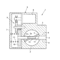
EGRバルブ1の具体的な一例を、図1を参照して説明する。
なお、以下では、図1の図示左側を左、図示右側を右と称して説明するが、この左右は実施例の説明のための方向であり、限定されるものではない。
EGRバルブ1は、
・内部にEGR流路2(具体的にはEGR流路2の一部)が形成されるハウジング3と、・EGR流路2内の中央を横切って配置され、右側がハウジング3に固定されるシャフト4と、
・このシャフト4の外周面に摺動自在に支持される円筒形状を呈するバルブパイプ5aを有し、EGR流路2の開閉および開度調整を行なう弁体5と、
・バルブパイプ5aを駆動してEGR流路2で弁体5を回動変位させる電動アクチュエータ6と、
を具備する。
A specific example of the EGR valve 1 will be described with reference to FIG.
In the following description, the left side of FIG. 1 is referred to as left, and the right side of FIG. 1 is referred to as right. However, the left and right directions are directions for explaining the embodiment and are not limited.
The EGR valve 1 is
A
A
An
It comprises.
ハウジング3は、例えばアルミニウム製であり、ハウジング3の内部にはEGR流路2が形成されている。
なお、弁体5によって開閉される部位のEGR流路2の内壁には、耐熱性、耐摩耗性に優れた材料(例えば、ステンレスなど)よりなる円筒形状を呈したノズル(図示しない)が圧入等により固定配置されるものである。
The
A cylindrical nozzle (not shown) made of a material having excellent heat resistance and wear resistance (for example, stainless steel) is press-fitted into the inner wall of the
シャフト4は、耐熱性、耐摩耗性に優れた材料(例えば、ステンレス等)よりなる円柱棒状を呈するもので、シャフト4の右側(図1の符号Aで示す範囲)がハウジング3に圧入固定されている。
シャフト4の左側のハウジング3には、EGR流路2の内部とハウジング3の左側を連通する貫通穴(シャフト挿通穴)が設けられており、シャフト4の左側はその貫通穴の内部に隙間(後述するギヤパイプ10aの組付隙間)を隔てて挿入配置されている。
なお、シャフト4の左端は、電動アクチュエータ6の収容室(ハウジング3とカバー7との間に形成される空間)の内部に達するように設けられている。
The
The
The left end of the
弁体5は、EGR流路2の内部に配置され、EGR流路2の内部(具体的には、ノズルの内部)で回動することで、EGR流路2の開閉および開度調整を行い、吸気通路へ戻されるEGRガス量の調整を行なうものである。
この弁体5は、略円盤形状を呈し、耐熱性、耐腐食性に優れた材料(例えば、ステンレス等)によって設けられる。
The
The
バルブパイプ5aは、弁体5と一体に設けられたパイプ形状を呈するものであり、EGR流路2内においてシャフト4の周囲に外嵌され、シャフト4に対して摺動自在に支持される。即ち、弁体5は、バルブパイプ5aを介してシャフト4の周囲に摺動自在に支持されるものである。
The
ここで、ハウジング3内に形成されるEGR流路2は、シャフト4の軸線に対して傾斜して設けられる。このため、全閉時にEGR流路2の中心軸線(EGRガスの流れ方向)に対して弁体5が垂直に配置されるように、弁体5は、シャフト4の軸線に対して円盤面(弁体5の厚み方向に対する垂直方向)が傾斜配置される。
Here, the
電動アクチュエータ6は、ハウジング3の左側に配置されて、シャフト4に外嵌された弁体5を回動駆動するものであり、
・通電により回転動力を発生する電動モータ8(例えば、通電量に応じた回転トルクを発生する周知の直流モータ)と、
・複数のギヤを組み合わせてなり、電動モータ8の出力トルクを増幅して弁体5に伝達する歯車減速機9と、
・この歯車減速機9の最終ギヤ10(大径のファイナルギヤ)に閉弁方向の付勢力を付与するリターンスプリングと、
・弁体5の開度を検出する回転角センサ(例えば、最終ギヤ10の角度を非接触で検出する磁気回転角センサ:図示しない)と、
を備える。
The
An
A
A return spring that applies a biasing force in the valve closing direction to the final gear 10 (large-diameter final gear) of the
A rotation angle sensor that detects the opening of the valve body 5 (for example, a magnetic rotation angle sensor that detects the angle of the
Is provided.
なお、電動モータ8は、ECUによって通電制御されるものであり、電動モータ8がECUによって通電制御されることで弁体5の開度制御が行なわれて、エンジンに戻されるEGRガス量の調整が行なわれる。
具体的にECUは、マイクロコンピュータを搭載した周知の電子制御装置であり、回転角センサによって検出される実際の弁体5の開度が、車両走行状態に応じて算出された目標開度となるように、ECUが電動モータ8を通電制御するものである。
The
Specifically, the ECU is a known electronic control device equipped with a microcomputer, and the actual opening of the
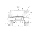
次に、電動アクチュエータ6の出力によって弁体5を駆動する動力伝達手段を図2を参照して説明する。
EGRバルブ1は、最終ギヤ10の出力トルクを弁体5のバルブパイプ5aに付与するギヤパイプ10aを備える。
このギヤパイプ10aは、歯車減速機9の最終ギヤ10と一体に設けられており、図1に示すようにハウジング3の左側に形成された貫通穴(シャフト挿通穴)の内部に挿入配置されて、シャフト4およびハウジング3に対して回動自在に支持される。
なお、ギヤパイプ10aを最終ギヤ10と別体に設けて最終ギヤ10に固定するものであっても良い。
Next, power transmission means for driving the
The EGR valve 1 includes a
The
The
ギヤパイプ10aの回動トルクをバルブパイプ5aに伝達する動力伝達部は、ギヤパイプ10aとバルブパイプ5aの軸方向の対向部に設けられた噛合部11によって行なわれる。
ギヤパイプ10aとバルブパイプ5aの対向部には、図2(b)に示すように、軸方向へ突出した凸部11aと、軸方向へ窪んだ凹部11bが設けられており、この凸部11aと凹部11bが軸方向で噛み合うことで噛合部11が構成され、最終ギヤ10と弁体5が高トルク伝達可能な状態で結合される。
The power transmission part for transmitting the rotational torque of the
As shown in FIG. 2B, a
噛合部11の具体的な一例を、図2(c)を参照して説明する。
この実施例の凸部11aと凹部11bは、それぞれテーパー形状に設けられている。
そして、凸部11aの根元の歯幅L1と、凹部11bの開口部の穴幅L2との関係が、「L1≧L2」に設けられており、後述する付勢手段13によって凸部11aと凹部11bが軸方向に押し付けられて嵌まり合うことで、回転方向のガタの発生が確実に無くなるように設けられている。
A specific example of the meshing
The
The relationship between the root tooth width L1 of the
ここで、シャフト4の右側には、バルブパイプ5aの右端が当接する段差肩部12が形成されている。この段差肩部12は、バルブパイプ5aの内径寸法より大径となる環状段差である。
一方、EGRバルブ1には、図2(a)に示すように、最終ギヤ10の回動を妨げることなく最終ギヤ10を右側へ付勢する付勢手段13が設けられている。この付勢手段13は、弁体5を閉弁方向へ付勢するリターンスプリングと共通のものであっても良いし、別に設けられるものであっても良い。
この実施例の付勢手段13は、カバー7と最終ギヤ10との間に圧縮配置された圧縮コイルバネであり、最終ギヤ10を右側へ付勢することで、
(i)ギヤパイプ10aの右端がバルブパイプ5aの左端に押し付けられるとともに、
(ii)バルブパイプ5aの右端が段差肩部12に押し付けられる。
なお、段差肩部12の段差面は平滑に形成されており、段差肩部12に押し付けられたバルブパイプ5aが容易に回動可能に設けられている。
Here, on the right side of the
On the other hand, as shown in FIG. 2A, the EGR valve 1 is provided with a biasing means 13 that biases the
The urging means 13 of this embodiment is a compression coil spring that is compressed between the
(I) While the right end of the
(Ii) The right end of the
In addition, the level | step difference surface of the level | step-
(実施例1の効果1)
この実施例のEGRバルブ1は、上述したように、シャフト4が固定され、バルブパイプ5aがシャフト4に対して摺動自在に支持されるため、EGR流路2に対して弁体5の偏心量を小さく抑えることができる。即ち、弁体5の振れや位置ズレを極めて小さく抑えることができる。
さらに、弁体5を含む可動部(弁体5+最終ギヤ10)はシャフト4とは別体であり、弁体5を含む可動部がシャフト4に対して回転自在に支持されるため、弁体5を含む可動部の重量が軽く設けられる。
(Effect 1 of Example 1)
In the EGR valve 1 of this embodiment, the
Further, the movable part (
このため、弁体5を含む可動部に振動が生じても、振動エネルギーが軽減され、振動による摩耗を抑えることができ、EGRバルブ1を長期に亘って使用しても摩耗によるEGRガスの漏れを防ぐことができる。即ち、EGRバルブ1を長期に亘って使用しても低弁漏れを実現することができ、高い信頼性を得ることができる。
また、バルブパイプ5aがシャフト4に摺動自在に支持されるものであるため、「従来技術においてシャフト4を回転自在に支持するための独立軸受(ボールベアリングJ1やメタルベアリングJ2の独立したベアリング類等:符号図11参照)」を廃止することができ、EGRバルブ1のコストを抑えることができる。
For this reason, even if vibration occurs in the movable part including the
Further, since the
(実施例1の効果2)
この実施例のEGRバルブ1は、付勢手段13が最終ギヤ10を右側へ付勢し、この最終ギヤ10に設けられたギヤパイプ10aの右端がバルブパイプ5aを右側へ付勢し、バルブパイプ5aの右端が段差肩部12に押し付けられる。
このように、付勢手段13によってバルブパイプ5aの右端が段差肩部12に押し付けられることにより、弁体5のガタを無くすことができる。
また、弁体5を含む可動部が付勢手段13により付勢されることで、弁体5を含む可動部の振動を抑えることができる。即ち、摩耗の要因となる可動部の振動を抑制することができる。
さらに、付勢手段13によってギヤパイプ10aの右端がバルブパイプ5aに押し付けられることにより、噛合部11のガタを無くすことができ、電動アクチュエータ6と弁体5との間にヒステリシスが生じることなく、電動アクチュエータ6の出力トルクをダイレクトに弁体5へ伝達することができる。
(
In the EGR valve 1 of this embodiment, the urging means 13 urges the
Thus, the back end of the
In addition, since the movable part including the
Furthermore, when the right end of the
[実施例2]
図3、図4を参照して実施例2を説明する。なお、以下の実施例において、上記実施例1と同一符号は同一機能物を示すものである。
この実施例2のEGRバルブ1は、弁体5の外周縁にシールリング14を設けたものである。
シールリング14は、EGR流路2の全閉時に弁体5の周囲の隙間(弁体5とEGR流路2の内壁との間)を閉塞するものであり、弁体5の外周縁に全周に亘って形成されたシール嵌合溝14aの内部に嵌め入れられたものである。
[Example 2]
A second embodiment will be described with reference to FIGS. In the following embodiments, the same reference numerals as those in the first embodiment denote the same functions.
In the EGR valve 1 of Example 2, a
The
このように、弁体5の外周縁にシールリング14を設けることにより、弁体5がEGR流路2の内壁に直接触れて振動するのを防ぐことができ、振動の吸収箇所を「弁体5とシールリング14の間」と「シールリング14とEGR流路2の内壁の間」に分散させることができる。
これによって、弁体5に生じた振動エネルギーを分散させることができるため、摩耗の発生をさらに抑えることができ、長期に亘ってEGRバルブ1の低弁漏れを実現することができる。
Thus, by providing the
As a result, vibration energy generated in the
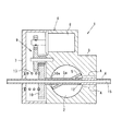
[実施例3]
図5を参照して実施例3を説明する。
シャフト4の内部に冷却水が循環供給される冷却水通路15を設けたものである。
この実施例の冷却水は、エンジン冷却水である。エンジン冷却水は、ラジエータによって外気と熱交換して放熱されるものであり、サーモスタットの作動により約80℃(100℃以下)に維持される。なお、冷却水は、エンジン冷却水に限定されるものではなく、例えば水冷インタークーラ用の冷却水を用いるなど、他の用途の冷却水を利用しても良い。
[Example 3]
A cooling
The cooling water in this embodiment is engine cooling water. The engine cooling water is radiated by heat exchange with the outside air by the radiator, and is maintained at about 80 ° C. (100 ° C. or less) by the operation of the thermostat. The cooling water is not limited to engine cooling water, and cooling water for other uses may be used, for example, cooling water for a water cooling intercooler.
シャフト4の両端はカバー7の外部とハウジング3の外部に突出して配置され、エンジン冷却水の循環経路に接続される。そして、エンジンの運転に伴うウォータポンプの作動によって、エンジン冷却水の一部がシャフト4の内部に形成された冷却水通路15に循環供給される。
Both ends of the
「水の熱エネルギーは、空気の数十倍」であるため、冷却水による冷却効果は非常に大きく、EGR流路2の排気熱が電動アクチュエータ6側へ伝わるのを防ぐことができる。このため、EGR流路2から電動アクチュエータ6の最終ギヤ10までの距離を短く設けることができ(EGR流路2の左側におけるハウジング3の肉厚を薄く設けることができ)、EGRバルブ1を小型化することが可能になる。
Since “the heat energy of water is several tens of times that of air”, the cooling effect by the cooling water is very large, and the exhaust heat of the
また、シャフト4を介してバルブパイプ5aを冷却するため、シャフト4とバルブパイプ5aとの間の潤滑手段として、熱を考慮することなくグリスやオイルを使用することができる。即ち、高価な耐熱性グリスを使用しなくて済むため、コストを抑えることができる。
Further, since the
さらに、バルブパイプ5aを介して弁体5を冷却することができるため、弁体5を成形性に優れた樹脂で製造することが可能になる。即ち、バルブパイプ5aを有する弁体5の複雑な形状を容易に製造することが可能になり、コストを抑えることができる。
Furthermore, since the
[実施例4]
図6を参照して実施例4を説明する。
この実施例のシャフト4には、バルブパイプ5a内に配置される範囲の中央部分に幅広のグリス保持溝16が形成され、グリス保持溝16の両側のシャフト4の外周面においてバルブパイプ5aを摺動自在に支持するものである。
グリス保持溝16の内部に潤滑用のグリスを塗り入れた状態でバルブパイプ5aが外嵌されて、グリス保持溝16の内部に潤滑用のグリスが保持される。
このように、バルブパイプ5aの内部にグリスを保持するグリス保持溝16を設けたことで、バルブパイプ5aの内部にグリスを長期に亘って蓄えることができ、長期に亘ってバルブパイプ5aの摺動性能を高く維持することができる。
なお、このグリス保持溝16は、上述した実施例1等にも設けられるものである。
[Example 4]
In the
The
Thus, by providing the
The
また、この実施例のEGRバルブ1には、最終ギヤ10とハウジング3の間に、最終ギヤ10とハウジング3に挟まれるシールリング17が配置される。
このシールリング17により、EGR流路2を流れる排気ガス等やデポジットが、電動アクチュエータ6の収容室に侵入するのを防ぐことができる。
Further, in the EGR valve 1 of this embodiment, a
The
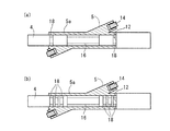
[実施例5]
図7を参照して実施例5を説明する。
この実施例のシャフト4には、バルブパイプ5a内に配置される範囲の両側に、潤滑用のグリスの保持あるいは異物の収容を行なうラビリンス溝18が形成されている。
なお、図7(a)は、グリス保持溝16の両側にそれぞれに1つのラビリンス溝18を設けるものであり、図7(b)は、グリス保持溝16の両側にそれぞれに複数(図面では3つ)のラビリンス溝18を設けるものである。
[Example 5]
In the
7A shows that one
ラビリンス溝18の内部にグリスを保持させることで、バルブパイプ5aの両端部(右端は段差肩部12)の摺動性能を高めることができる。
また、デポジットがバルブパイプ5aの端部からシャフト4とバルブパイプ5aの間に侵入したとしても、侵入したデポジットをラビリンス溝18の内部に収容して、デポジットによってシャフト4とバルブパイプ5aの摺動性能が劣化する不具合を回避することができる。
By holding the grease inside the
Even if a deposit enters between the
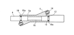
[実施例6]
図8を参照して実施例6を説明する。
この実施例のシャフト4には、バルブパイプ5a内に配置される範囲の両側に、シャフト4とバルブパイプ5aとの隙間を閉塞するシールリング19を嵌め入れるシール溝19aが形成されている。
このシール溝19aに配置されるシールリング19によって、デポジットがシャフト4とバルブパイプ5aの間に侵入するのを防ぐことができ、デポジットによってシャフト4とバルブパイプ5aの摺動性能が劣化する不具合を回避することができる。
[Example 6]
Example 6 will be described with reference to FIG.
The
The
また、図8に示すように、グリス保持溝16と組み合わせて用いることにより、グリス保持溝16の内部に蓄えられたグリスが、シール溝19aに配置されるシールリング19によって外部へ流れ出るのを防ぐことができ、長期に亘ってバルブパイプ5aの摺動性能を高く維持することができる。
Further, as shown in FIG. 8, by using in combination with the
[実施例7]
図9を参照して実施例7を説明する。
この実施例のEGRバルブ1には、図9(a)に示すように、ギヤパイプ10aのバルブパイプ5a側に、バルブパイプ5aの周囲を覆い被せるシール嵌合部20が設けられている。
このシール嵌合部20は、バルブパイプ5aの左端の外周を全周に亘って覆う筒状部であり、この実施例ではシール嵌合部20の内側にバルブパイプ5aの左端が圧入固定されるものである。
このシール嵌合部20により、デポジットがシャフト4とバルブパイプ5aとの間に侵入するのを防ぐことができる。
[Example 7]
As shown in FIG. 9A, the EGR valve 1 of this embodiment is provided with a seal
The seal
The seal
なお、この実施例においてギヤパイプ10aの回動トルクをバルブパイプ5aに伝達する動力伝達部は、ギヤパイプ10aのシール嵌合部20とバルブパイプ5aの圧入により行なわれる。
具体的に、シール嵌合部20とバルブパイプ5aの圧入部には、径方向に噛合する噛合部が設けられており{図9(b)に示すシール嵌合部20の内周面に形成された軸方向のスプライン嵌合部20a参照}、最終ギヤ10と弁体5を高トルク伝達可能な状態に結合している。
In this embodiment, the power transmission portion for transmitting the rotational torque of the
Specifically, the press-fitting portion of the
また、この実施例のEGRバルブ1は、バルブパイプ5aと段差肩部12の間に、バルブパイプ5aと段差肩部12に挟まれるシールリング21を配置している。
このシールリング21により、バルブパイプ5aの右端からデポジットが、シャフト4とバルブパイプ5aとの間に侵入するのを防ぐことができる。
また、このシールリング21を「摩擦係数の小さい低μの材料(例えば、四フッ化エチレン樹脂等)」で設けることにより、シャフト4に対するバルブパイプ5aの摺動抵抗を小さくすることができ、電動アクチュエータ6の駆動負荷を小さくすることができる。
In the EGR valve 1 of this embodiment, a
The
Further, by providing this
さらに、この実施例のEGRバルブ1は、ハウジング3とギヤパイプ10aの間に、ハウジング3とギヤパイプ10aの摺動クリアランスを閉塞するシールリング22が配置される。
このシールリング22により、EGR流路2を流れる排気ガスやデポジットが、電動アクチュエータ6の収容室に侵入するのを防ぐことができる。
Further, in the EGR valve 1 of this embodiment, a
The
[実施例8]
図10を参照して実施例8を説明する。
上記の各実施例では、EGRバルブ1の一例として、シャフト4に対して弁体5が傾斜配置される例を示した。
これに対し、この実施例のEGRバルブ1は、シャフト4に対して弁体5が平行配置されるものである。具体的に、この実施例のEGRバルブ1は、シャフト4の軸芯に対して弁体5がオフセット配置されるものである。
[Example 8]
In each of the above embodiments, as an example of the EGR valve 1, the example in which the
On the other hand, in the EGR valve 1 of this embodiment, the
上記の各実施例を組み合わせて用いても良い。
上記の実施例では、本発明をEGRバルブ1に適用する例を示したが、流体は排気ガスに限定されるものではなく、他の気体流体や液体流体の開閉や、流量または圧力調整を行なうバタフライバルブ(例えば、スロットルバルブ等)に本発明を適用しても良い。
You may use combining said each Example.
In the above embodiment, the example in which the present invention is applied to the EGR valve 1 is shown. However, the fluid is not limited to the exhaust gas, and other gas fluids and liquid fluids are opened and closed, and the flow rate or pressure is adjusted. You may apply this invention to a butterfly valve (for example, throttle valve etc.).
上記の実施例では、バルブ駆動手段の一例として電動アクチュエータ6を用いる例を示したが、弁体5に回動力を付与する手段は限定されるものではなく、流体圧アクチュエータ(例えば、負圧アクチュエータ、油圧アクチュエータ等)や手動など、他のバルブ駆動手段を用いても良い。
In the above embodiment, an example in which the
1 EGRバルブ(バタフライバルブ)
2 EGR流路(流体通路)
3 ハウジング
4 シャフト
5 弁体
5a バルブパイプ
6 電動アクチュエータ(バルブ駆動手段)
8 電動モータ
9 歯車減速機
10 最終ギヤ
10a ギヤパイプ
11 噛合部
12 段差肩部
13 付勢手段
14 弁体の外周縁に設けられるシールリング
14a シール嵌合溝
15 冷却水通路
16 グリス保持溝
17 最終ギヤとハウジングに挟まれるシールリング
18 ラビリンス溝
19 シャフトのシール溝に配置されるシールリング
19a シャフトのシール溝
20 シール嵌合部
21 バルブパイプと段差肩部に挟まれるシールリング
22 ハウジングとギヤパイプの間に配置されるシールリング
1 EGR valve (butterfly valve)
2 EGR flow path (fluid path)
3
DESCRIPTION OF
Claims (13)
前記流体通路(2)内を横切って配置され、前記ハウジング(3)に固定されるシャフト(4)と、
前記シャフト(4)の外周面に対して摺動自在に支持されるバルブパイプ(5a)を備え、前記流体通路(2)の開閉あるいは開度調整を行なう弁体(5)と、
前記バルブパイプ(5a)に回動方向の駆動力を付与するバルブ駆動手段(6)と、
を具備するバタフライバルブ。 A housing (3) in which a fluid passage (2) is formed;
A shaft (4) disposed across the fluid passage (2) and secured to the housing (3);
A valve body (5) that includes a valve pipe (5a) that is slidably supported with respect to the outer peripheral surface of the shaft (4), and that opens / closes or adjusts the opening of the fluid passage (2);
Valve driving means (6) for applying a driving force in the rotational direction to the valve pipe (5a);
A butterfly valve.
このバタフライバルブ(1)は、前記弁体(5)の外周縁に形成されたシール嵌合溝(14a)の内部に嵌め入れられ、前記流体通路(2)の全閉時に前記弁体(5)の周囲の隙間を閉塞するシールリング(14)を備えることを特徴とするバタフライバルブ。 The butterfly valve (1) according to claim 1,
The butterfly valve (1) is fitted into a seal fitting groove (14a) formed in the outer peripheral edge of the valve body (5), and the valve body (5) when the fluid passage (2) is fully closed. A butterfly valve comprising a seal ring (14) for closing a gap around
このバタフライバルブ(1)は、排気ガス還流装置のEGRバルブに適用されるものであり、
前記シャフト(4)の内部には、冷却水が循環供給される冷却水通路(15)が設けられることを特徴とするバタフライバルブ。 The butterfly valve (1) according to claim 1 or claim 2,
This butterfly valve (1) is applied to an EGR valve of an exhaust gas recirculation device,
A butterfly valve characterized in that a cooling water passage (15) through which cooling water is circulated and supplied is provided in the shaft (4).
前記バルブ駆動手段(6)は、通電により回転出力を発生する電動モータ(8)と、この電動モータ(8)の回転出力を減速して前記バルブパイプ(5a)に伝える歯車減速機(9)とを備える電動アクチュエータであり、
前記歯車減速機(9)の最終ギヤ(10)は、前記シャフト(4)の周囲において回動自在に支持されるギヤパイプ(10a)を有することを特徴とするバタフライバルブ。 In the butterfly valve (1) according to claims 1-3,
The valve drive means (6) includes an electric motor (8) that generates a rotational output when energized, and a gear reducer (9) that decelerates the rotational output of the electric motor (8) and transmits it to the valve pipe (5a). An electric actuator comprising:
The butterfly valve characterized in that the final gear (10) of the gear reducer (9) has a gear pipe (10a) supported rotatably around the shaft (4).
前記ギヤパイプ(10a)と前記バルブパイプ(5a)の動力伝達部は、軸方向に噛み合う噛合部(11)によって設けられることを特徴とするバタフライバルブ。 The butterfly valve (1) according to claim 4,
The butterfly valve characterized in that the power transmission part of the gear pipe (10a) and the valve pipe (5a) is provided by a meshing part (11) meshing in the axial direction.
前記ギヤパイプ(10a)の前記バルブパイプ(5a)側には、前記バルブパイプ(5a)の周囲を覆い被せるシール嵌合部(20)が設けられることを特徴とするバタフライバルブ。 In the butterfly valve (1) according to claim 4 or 5,
A butterfly valve characterized in that a seal fitting portion (20) for covering the periphery of the valve pipe (5a) is provided on the side of the valve pipe (5a) of the gear pipe (10a).
前記シャフト(4)は、前記バルブパイプ(5a)の一端が当接する段差肩部(12)を備え、
前記バタフライバルブ(1)は、前記最終ギヤ(10)を介して前記バルブパイプ(5a)を前記段差肩部(12)に押し付ける付勢手段(13)を備えることを特徴とするバタフライバルブ。 In the butterfly valve (1) according to any one of claims 4 to 6,
The shaft (4) includes a step shoulder (12) with which one end of the valve pipe (5a) abuts.
The butterfly valve (1) includes a biasing means (13) for pressing the valve pipe (5a) against the step shoulder (12) through the final gear (10).
前記バルブパイプ(5a)と前記段差肩部(12)の間には、前記バルブパイプ(5a)と前記段差肩部(12)に挟まれるシールリング(21)が配置されることを特徴とするバタフライバルブ。 The butterfly valve (1) according to claim 7,
A seal ring (21) sandwiched between the valve pipe (5a) and the step shoulder (12) is disposed between the valve pipe (5a) and the step shoulder (12). Butterfly valve.
前記最終ギヤ(10)と前記ハウジング(3)の間には、前記最終ギヤ(10)と前記ハウジング(3)に挟まれるシールリング(17)が配置されることを特徴とするバタフライバルブ。 In the butterfly valve (1) according to claim 7 or claim 8,
A butterfly valve characterized in that a seal ring (17) sandwiched between the final gear (10) and the housing (3) is disposed between the final gear (10) and the housing (3).
前記ハウジング(3)と前記ギヤパイプ(10a)の間には、前記ハウジング(3)と前記ギヤパイプ(10a)の摺動クリアランスを閉塞するシールリング(22)が配置されることを特徴とするバタフライバルブ。 In the butterfly valve (1) according to any one of claims 4 to 9,
A butterfly valve characterized in that a seal ring (22) for closing a sliding clearance between the housing (3) and the gear pipe (10a) is disposed between the housing (3) and the gear pipe (10a). .
前記シャフト(4)は、前記バルブパイプ(5a)内に配置される範囲の中央部分に、潤滑用のグリスを保持するグリス保持溝(16)を有することを特徴とするバタフライバルブ。 In the butterfly valve (1) according to any of claims 1 to 10,
The said shaft (4) has a grease holding groove (16) which hold | maintains the grease for lubrication in the center part of the range arrange | positioned in the said valve pipe (5a), The butterfly valve characterized by the above-mentioned.
前記シャフト(4)は、前記バルブパイプ(5a)内に配置される範囲の両側に、潤滑用のグリスの保持あるいは異物の収容を行なうラビリンス溝(18)を有することを特徴とするバタフライバルブ。 In the butterfly valve (1) according to any one of claims 1 to 11,
The said shaft (4) has the labyrinth groove | channel (18) which hold | maintains the grease for lubrication or accommodates a foreign material on both sides of the range arrange | positioned in the said valve pipe (5a), The butterfly valve characterized by the above-mentioned.
前記シャフト(4)は、前記バルブパイプ(5a)内に配置される範囲の両側に、前記シャフト(4)と前記バルブパイプ(5a)との隙間を閉塞するシールリング(19)を嵌め入れるシール溝(19a)を有することを特徴とするバタフライバルブ。 In the butterfly valve (1) according to any one of claims 1 to 11,
The shaft (4) is a seal in which a seal ring (19) for closing a gap between the shaft (4) and the valve pipe (5a) is fitted on both sides of the range in which the shaft (4a) is disposed. A butterfly valve having a groove (19a).
Priority Applications (1)
| Application Number | Priority Date | Filing Date | Title |
|---|---|---|---|
| JP2011023125A JP2012163017A (en) | 2011-02-04 | 2011-02-04 | Butterfly valve |
Applications Claiming Priority (1)
| Application Number | Priority Date | Filing Date | Title |
|---|---|---|---|
| JP2011023125A JP2012163017A (en) | 2011-02-04 | 2011-02-04 | Butterfly valve |
Publications (1)
| Publication Number | Publication Date |
|---|---|
| JP2012163017A true JP2012163017A (en) | 2012-08-30 |
Family
ID=46842641
Family Applications (1)
| Application Number | Title | Priority Date | Filing Date |
|---|---|---|---|
| JP2011023125A Withdrawn JP2012163017A (en) | 2011-02-04 | 2011-02-04 | Butterfly valve |
Country Status (1)
| Country | Link |
|---|---|
| JP (1) | JP2012163017A (en) |
Cited By (6)
| Publication number | Priority date | Publication date | Assignee | Title |
|---|---|---|---|---|
| KR101362058B1 (en) | 2012-12-17 | 2014-02-12 | 기아자동차 주식회사 | Exhaust gas recirculation valve for vehicle |
| JP2015124640A (en) * | 2013-12-26 | 2015-07-06 | 株式会社デンソー | EGR valve device |
| CN104791538A (en) * | 2014-01-22 | 2015-07-22 | 无锡市鸿声船用玻璃钢有限公司 | Diesel engine throttle valve |
| JP2018506816A (en) * | 2014-12-19 | 2018-03-08 | コンチネンタル オートモーティヴ ゲゼルシャフト ミット ベシュレンクテル ハフツングContinental Automotive GmbH | Valve devices installed in automobiles |
| CN109372995A (en) * | 2018-11-20 | 2019-02-22 | 南京清元景和环境科技有限公司 | Manually adjust air-valve |
| CN112815102A (en) * | 2021-01-22 | 2021-05-18 | 闵江 | Prevent dead butterfly valve of impurity card |
-
2011
- 2011-02-04 JP JP2011023125A patent/JP2012163017A/en not_active Withdrawn
Cited By (6)
| Publication number | Priority date | Publication date | Assignee | Title |
|---|---|---|---|---|
| KR101362058B1 (en) | 2012-12-17 | 2014-02-12 | 기아자동차 주식회사 | Exhaust gas recirculation valve for vehicle |
| JP2015124640A (en) * | 2013-12-26 | 2015-07-06 | 株式会社デンソー | EGR valve device |
| CN104791538A (en) * | 2014-01-22 | 2015-07-22 | 无锡市鸿声船用玻璃钢有限公司 | Diesel engine throttle valve |
| JP2018506816A (en) * | 2014-12-19 | 2018-03-08 | コンチネンタル オートモーティヴ ゲゼルシャフト ミット ベシュレンクテル ハフツングContinental Automotive GmbH | Valve devices installed in automobiles |
| CN109372995A (en) * | 2018-11-20 | 2019-02-22 | 南京清元景和环境科技有限公司 | Manually adjust air-valve |
| CN112815102A (en) * | 2021-01-22 | 2021-05-18 | 闵江 | Prevent dead butterfly valve of impurity card |
Similar Documents
| Publication | Publication Date | Title |
|---|---|---|
| US9567894B2 (en) | Rotary valve | |
| JP2012163017A (en) | Butterfly valve | |
| JP4687540B2 (en) | Fluid control valve | |
| US20150075453A1 (en) | Rotary valve | |
| US20120193562A1 (en) | Structure for reducing axial leakage of valve | |
| JP6062129B2 (en) | Fluid control valve | |
| JP5304825B2 (en) | EGR valve | |
| JP2020128711A (en) | Cooling water control valve device | |
| JP4367628B2 (en) | Electric motor integrated turbocharger | |
| CA2720788C (en) | Engine control valve system with motor | |
| JP2011196464A (en) | Ball valve type valve device | |
| US10330025B2 (en) | Valve device | |
| JP5626270B2 (en) | EGR valve | |
| JP2008196437A (en) | Exhaust gas control valve | |
| US20180003134A1 (en) | Egr device | |
| JP2014105764A (en) | Valve device | |
| JP5360018B2 (en) | Seal ring and manufacturing method thereof | |
| JP2019002497A (en) | Shell-type roller bearing | |
| JP2012107572A (en) | Egr valve | |
| JP2019157905A (en) | Control valve | |
| JP2012172519A (en) | Flap valve | |
| JP2009002325A (en) | Fluid control valve | |
| JP2012219890A (en) | Valve unit | |
| WO2022202423A1 (en) | Electric pump | |
| JP5527189B2 (en) | EGR valve |
Legal Events
| Date | Code | Title | Description |
|---|---|---|---|
| A300 | Withdrawal of application because of no request for examination |
Free format text: JAPANESE INTERMEDIATE CODE: A300 Effective date: 20140513 |