WO2021020029A1 - Vehicle-mounted power supply system - Google Patents
Vehicle-mounted power supply system Download PDFInfo
- Publication number
- WO2021020029A1 WO2021020029A1 PCT/JP2020/026188 JP2020026188W WO2021020029A1 WO 2021020029 A1 WO2021020029 A1 WO 2021020029A1 JP 2020026188 W JP2020026188 W JP 2020026188W WO 2021020029 A1 WO2021020029 A1 WO 2021020029A1
- Authority
- WO
- WIPO (PCT)
- Prior art keywords
- storage device
- power
- power storage
- supply system
- power supply
- Prior art date
Links
- 238000010248 power generation Methods 0.000 claims abstract description 34
- 239000003990 capacitor Substances 0.000 claims description 9
- 229910001416 lithium ion Inorganic materials 0.000 claims description 9
- HBBGRARXTFLTSG-UHFFFAOYSA-N Lithium ion Chemical compound [Li+] HBBGRARXTFLTSG-UHFFFAOYSA-N 0.000 claims description 5
- 238000010586 diagram Methods 0.000 description 7
- 230000000052 comparative effect Effects 0.000 description 4
- 238000007599 discharging Methods 0.000 description 3
- QAOWNCQODCNURD-UHFFFAOYSA-N Sulfuric acid Chemical compound OS(O)(=O)=O QAOWNCQODCNURD-UHFFFAOYSA-N 0.000 description 2
- 230000005611 electricity Effects 0.000 description 2
- 229910052739 hydrogen Inorganic materials 0.000 description 2
- 239000001257 hydrogen Substances 0.000 description 2
- 238000000034 method Methods 0.000 description 2
- 229910052759 nickel Inorganic materials 0.000 description 2
- PXHVJJICTQNCMI-UHFFFAOYSA-N nickel Substances [Ni] PXHVJJICTQNCMI-UHFFFAOYSA-N 0.000 description 2
- HEZMWWAKWCSUCB-PHDIDXHHSA-N (3R,4R)-3,4-dihydroxycyclohexa-1,5-diene-1-carboxylic acid Chemical compound O[C@@H]1C=CC(C(O)=O)=C[C@H]1O HEZMWWAKWCSUCB-PHDIDXHHSA-N 0.000 description 1
- 208000032368 Device malfunction Diseases 0.000 description 1
- 230000005856 abnormality Effects 0.000 description 1
- 239000002253 acid Substances 0.000 description 1
- 230000006866 deterioration Effects 0.000 description 1
- 239000008151 electrolyte solution Substances 0.000 description 1
- 230000007257 malfunction Effects 0.000 description 1
- 239000000463 material Substances 0.000 description 1
- 230000001172 regenerating effect Effects 0.000 description 1
Images


Classifications
-
- B—PERFORMING OPERATIONS; TRANSPORTING
- B60—VEHICLES IN GENERAL
- B60R—VEHICLES, VEHICLE FITTINGS, OR VEHICLE PARTS, NOT OTHERWISE PROVIDED FOR
- B60R16/00—Electric or fluid circuits specially adapted for vehicles and not otherwise provided for; Arrangement of elements of electric or fluid circuits specially adapted for vehicles and not otherwise provided for
- B60R16/02—Electric or fluid circuits specially adapted for vehicles and not otherwise provided for; Arrangement of elements of electric or fluid circuits specially adapted for vehicles and not otherwise provided for electric constitutive elements
- B60R16/03—Electric or fluid circuits specially adapted for vehicles and not otherwise provided for; Arrangement of elements of electric or fluid circuits specially adapted for vehicles and not otherwise provided for electric constitutive elements for supply of electrical power to vehicle subsystems or for
- B60R16/0315—Electric or fluid circuits specially adapted for vehicles and not otherwise provided for; Arrangement of elements of electric or fluid circuits specially adapted for vehicles and not otherwise provided for electric constitutive elements for supply of electrical power to vehicle subsystems or for using multiplexing techniques
-
- B—PERFORMING OPERATIONS; TRANSPORTING
- B60—VEHICLES IN GENERAL
- B60R—VEHICLES, VEHICLE FITTINGS, OR VEHICLE PARTS, NOT OTHERWISE PROVIDED FOR
- B60R16/00—Electric or fluid circuits specially adapted for vehicles and not otherwise provided for; Arrangement of elements of electric or fluid circuits specially adapted for vehicles and not otherwise provided for
- B60R16/02—Electric or fluid circuits specially adapted for vehicles and not otherwise provided for; Arrangement of elements of electric or fluid circuits specially adapted for vehicles and not otherwise provided for electric constitutive elements
- B60R16/03—Electric or fluid circuits specially adapted for vehicles and not otherwise provided for; Arrangement of elements of electric or fluid circuits specially adapted for vehicles and not otherwise provided for electric constitutive elements for supply of electrical power to vehicle subsystems or for
- B60R16/033—Electric or fluid circuits specially adapted for vehicles and not otherwise provided for; Arrangement of elements of electric or fluid circuits specially adapted for vehicles and not otherwise provided for electric constitutive elements for supply of electrical power to vehicle subsystems or for characterised by the use of electrical cells or batteries
-
- H—ELECTRICITY
- H02—GENERATION; CONVERSION OR DISTRIBUTION OF ELECTRIC POWER
- H02J—CIRCUIT ARRANGEMENTS OR SYSTEMS FOR SUPPLYING OR DISTRIBUTING ELECTRIC POWER; SYSTEMS FOR STORING ELECTRIC ENERGY
- H02J7/00—Circuit arrangements for charging or depolarising batteries or for supplying loads from batteries
- H02J7/14—Circuit arrangements for charging or depolarising batteries or for supplying loads from batteries for charging batteries from dynamo-electric generators driven at varying speed, e.g. on vehicle
- H02J7/1423—Circuit arrangements for charging or depolarising batteries or for supplying loads from batteries for charging batteries from dynamo-electric generators driven at varying speed, e.g. on vehicle with multiple batteries
-
- H—ELECTRICITY
- H02—GENERATION; CONVERSION OR DISTRIBUTION OF ELECTRIC POWER
- H02J—CIRCUIT ARRANGEMENTS OR SYSTEMS FOR SUPPLYING OR DISTRIBUTING ELECTRIC POWER; SYSTEMS FOR STORING ELECTRIC ENERGY
- H02J7/00—Circuit arrangements for charging or depolarising batteries or for supplying loads from batteries
- H02J7/14—Circuit arrangements for charging or depolarising batteries or for supplying loads from batteries for charging batteries from dynamo-electric generators driven at varying speed, e.g. on vehicle
- H02J7/16—Regulation of the charging current or voltage by variation of field
-
- H—ELECTRICITY
- H02—GENERATION; CONVERSION OR DISTRIBUTION OF ELECTRIC POWER
- H02J—CIRCUIT ARRANGEMENTS OR SYSTEMS FOR SUPPLYING OR DISTRIBUTING ELECTRIC POWER; SYSTEMS FOR STORING ELECTRIC ENERGY
- H02J7/00—Circuit arrangements for charging or depolarising batteries or for supplying loads from batteries
- H02J7/34—Parallel operation in networks using both storage and other dc sources, e.g. providing buffering
- H02J7/345—Parallel operation in networks using both storage and other dc sources, e.g. providing buffering using capacitors as storage or buffering devices
-
- H—ELECTRICITY
- H02—GENERATION; CONVERSION OR DISTRIBUTION OF ELECTRIC POWER
- H02J—CIRCUIT ARRANGEMENTS OR SYSTEMS FOR SUPPLYING OR DISTRIBUTING ELECTRIC POWER; SYSTEMS FOR STORING ELECTRIC ENERGY
- H02J2310/00—The network for supplying or distributing electric power characterised by its spatial reach or by the load
- H02J2310/40—The network being an on-board power network, i.e. within a vehicle
- H02J2310/46—The network being an on-board power network, i.e. within a vehicle for ICE-powered road vehicles
-
- H—ELECTRICITY
- H02—GENERATION; CONVERSION OR DISTRIBUTION OF ELECTRIC POWER
- H02J—CIRCUIT ARRANGEMENTS OR SYSTEMS FOR SUPPLYING OR DISTRIBUTING ELECTRIC POWER; SYSTEMS FOR STORING ELECTRIC ENERGY
- H02J2310/00—The network for supplying or distributing electric power characterised by its spatial reach or by the load
- H02J2310/40—The network being an on-board power network, i.e. within a vehicle
- H02J2310/48—The network being an on-board power network, i.e. within a vehicle for electric vehicles [EV] or hybrid vehicles [HEV]
-
- H—ELECTRICITY
- H02—GENERATION; CONVERSION OR DISTRIBUTION OF ELECTRIC POWER
- H02J—CIRCUIT ARRANGEMENTS OR SYSTEMS FOR SUPPLYING OR DISTRIBUTING ELECTRIC POWER; SYSTEMS FOR STORING ELECTRIC ENERGY
- H02J7/00—Circuit arrangements for charging or depolarising batteries or for supplying loads from batteries
- H02J7/0013—Circuit arrangements for charging or depolarising batteries or for supplying loads from batteries acting upon several batteries simultaneously or sequentially
Definitions
- the present invention has been made in view of the above situation, and it is an object to be solved to provide an in-vehicle power supply system having high reliability and durability without using a lead battery.
- the first switch and the second switch are turned off to disconnect the primary side power storage device, and power is supplied by the power generation device and the secondary side power storage device. Can be continued and the vehicle can run stably.
- the power supply system of the present invention does not require redundancy of the primary side power storage device, and the secondary side power storage device can be made small and small in capacity, so that the vehicle weight can be reduced while maintaining the reliability of the entire power supply system. be able to.
- FIG. 1 is a diagram schematically showing a configuration of a power supply system according to a preferred embodiment of the present invention.
- FIG. 2 is a diagram schematically showing a configuration of a power supply system according to a preferred embodiment of the present invention.
- FIG. 3 is a diagram schematically showing a power supply state when the primary side power storage device is operating normally.
- FIG. 4 is a diagram schematically showing a power supply state when a malfunction occurs in the primary power storage device.
- FIG. 5 is a diagram schematically showing a configuration of a power supply system of the prior art.
- FIG. 6 is a diagram showing an example of the configuration of the power supply system of the comparative example.
- the secondary side power storage device is a power storage device that supplies low-voltage power as an auxiliary power source during normal operation.
- the secondary side power storage device is a power storage device capable of supplying electric power to various loads with different voltages in cooperation with the power generation device when a problem occurs in the primary side power storage device.
- the power generation device in the present invention is a device that includes a generator and supplies electric power to a load and a power storage device.
- the generator referred to here is a motor that generates electricity with regenerative energy, an alternator that generates electricity using the engine of the vehicle as a power source, and other power supply devices for the vehicle.
Abstract
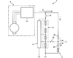
Provided is a vehicle-mounted power supply system that multiplexes power supplies in a vehicle and reliably supplies power of a voltage varying from a high voltage to a low voltage, without using a lead battery. A vehicle-mounted power supply system 1 according to the present invention is provided with a primary power storage device 2, a secondary power storage device 3, and a power generation device 4. The primary power storage device 2 has a high-voltage output terminal 11 and a low-voltage output terminal 12. The power generation device 4 supplies power to the primary power storage device 2 and the secondary power storage device 3. The power supply system 1 is further provided with: a first switch 21 disposed between the power generation device 4 and the primary power storage device 2; a second switch 22 disposed between the power generation device 4 and the secondary power storage device 3; and a third switch 23 disposed between the low-voltage output terminal 12 of the primary power storage device 2 and the output terminal 13 of the secondary power storage device. The power supply system 1 is characterized in that the power generation device 4 is a power generator 42 provided with an inverter 41, or a power generator that can output a variable voltage.
Description
本発明は、車載用電源システムに関する。特に、発電装置と蓄電装置とを備えており、二以上の異なる電圧で電力を供給する車載用電源システムに関する。
The present invention relates to an in-vehicle power supply system. In particular, the present invention relates to an in-vehicle power supply system that includes a power generation device and a power storage device and supplies power with two or more different voltages.
車両に搭載可能で、48Vまたは24Vの高電圧の電力を供給することのできる蓄電装置として、複数のセル(単電池)を直列に接続したバッテリが知られている。このような高電圧の蓄電装置は、主に、車両を駆動するモータなどに給電を行っている。通常、高電圧の蓄電装置を搭載した車両では、電気系統の装備品等への給電のために、低電圧電力を供給する蓄電装置が、別途搭載されている。
A battery in which a plurality of cells (cells) are connected in series is known as a power storage device that can be mounted on a vehicle and can supply high voltage power of 48V or 24V. Such a high-voltage power storage device mainly supplies power to a motor or the like that drives a vehicle. Normally, a vehicle equipped with a high-voltage power storage device is separately equipped with a power storage device that supplies low-voltage power for supplying power to electrical equipment and the like.
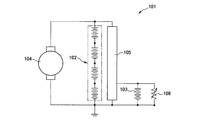
図5は、従来知られている電源システム101の構成を模式的に示した図である。電源システム101は、高電圧の電力を供給する蓄電装置102と負荷106に低電圧電力を供給する蓄電装置103とを備えている。それぞれの蓄電装置102,103は発電機104から給電される。蓄電装置102と蓄電装置103の間には、DCDCコンバータが配置されており、蓄電装置103側には、降圧された電力が供給される。
FIG. 5 is a diagram schematically showing the configuration of a conventionally known power supply system 101. The power supply system 101 includes a power storage device 102 that supplies high-voltage power and a power storage device 103 that supplies low-voltage power to the load 106. The power storage devices 102 and 103 are supplied with power from the generator 104. A DCDC converter is arranged between the power storage device 102 and the power storage device 103, and step-down electric power is supplied to the power storage device 103 side.
車両に搭載される電源システムには、高い信頼性と耐久性が要求される。そこで、高電圧の蓄電装置と低電圧の蓄電装置の一方に不具合が生じた場合であっても、正常な蓄電装置から電力を供給して、車両の動作を継続させることのできる構成が、求められている。例えば、特許文献1には、高電圧の蓄電体としてリチウムイオンバッテリを備え、低電圧の蓄電体として鉛バッテリを備えた電源装置が開示されている。特許文献1は、リチウムイオンバッテリと鉛バッテリの導通と遮断を制御するスイッチ制御部によって、センサ異常が発生した場合でも車両用電源を適切に制御する技術が開示されている。
High reliability and durability are required for the power supply system installed in the vehicle. Therefore, even if one of the high-voltage power storage device and the low-voltage power storage device has a problem, a configuration capable of supplying electric power from the normal power storage device to continue the operation of the vehicle is required. Has been done. For example, Patent Document 1 discloses a power supply device including a lithium ion battery as a high-voltage storage body and a lead battery as a low-voltage storage body. Patent Document 1 discloses a technique of appropriately controlling a vehicle power supply even when a sensor abnormality occurs by a switch control unit that controls continuity and disconnection between a lithium ion battery and a lead battery.
特許文献1に開示されているように、低電圧電力を供給する蓄電装置として、鉛蓄電池が広く普及している。鉛バッテリは、安価な材料で製造することができ、大電流の放電に耐えられる安定性の高い蓄電装置である。一方で、電極に鉛を使用するため、電源システム全体が重くなる傾向がある。また、電解液が硫酸を使用するため、万一の破損の際の危険性が指摘されている。このため、鉛バッテリを用いずに、信頼性の高い電源システムを提供する技術が求められている。
As disclosed in Patent Document 1, lead-acid batteries are widely used as power storage devices for supplying low-voltage power. A lead battery is a highly stable power storage device that can be manufactured from an inexpensive material and can withstand a large current discharge. On the other hand, since lead is used for the electrodes, the entire power supply system tends to be heavy. In addition, since sulfuric acid is used as the electrolytic solution, it has been pointed out that there is a risk of damage in the unlikely event. Therefore, there is a demand for a technique for providing a highly reliable power supply system without using a lead battery.
鉛バッテリを用いることなく、車両における電源を多重化し、高電圧から低電圧まで異なる電圧の電力を信頼性高く供給することのできる車載用電源システムが求められている。
There is a demand for an in-vehicle power supply system that can multiplex the power supply in a vehicle and supply power of different voltages from high voltage to low voltage with high reliability without using a lead battery.
本発明は上記現状に鑑みてなされたものであって、鉛バッテリを用いることなく、信頼性と耐久性の高い車載用の電源システムを提供することを、解決すべき課題としている。
The present invention has been made in view of the above situation, and it is an object to be solved to provide an in-vehicle power supply system having high reliability and durability without using a lead battery.
請求項1にかかる発明は、車載用の電源システムに関する。本発明の電源システムは、高電圧出力端子と低電圧出力端子とを有する一次側蓄電装置と、二次側蓄電装置と、一次側蓄電装置及び二次側蓄電装置に電力を供給する発電装置とを備えている。さらに本発明の電源システムは、発電装置と一次側蓄電装置との間に配置された第一のスイッチと、発電装置と二次側蓄電装置との間に配置された第二のスイッチと、一次側蓄電装置の低電圧出力端子と二次側蓄電装置の出力端子との間に配置された第三のスイッチと、を備えている。本発明の電源システムは、発電装置が、インバータを備えた発電機、又は可変電圧出力可能な発電機であることを特徴とする。
The invention according to claim 1 relates to an in-vehicle power supply system. The power supply system of the present invention includes a primary side power storage device having a high voltage output terminal and a low voltage output terminal, a secondary side power storage device, and a power generation device that supplies power to the primary side power storage device and the secondary side power storage device. It has. Further, in the power supply system of the present invention, a first switch arranged between the power generation device and the primary side power storage device, a second switch arranged between the power generation device and the secondary side power storage device, and a primary switch are provided. It includes a third switch arranged between the low voltage output terminal of the side power storage device and the output terminal of the secondary side power storage device. The power supply system of the present invention is characterized in that the power generation device is a generator equipped with an inverter or a generator capable of outputting a variable voltage.
本発明の電源システムは、二次側蓄電装置が、リチウムイオンバッテリ、電気二重層コンデンサ、または電解コンデンサのいずれかで構成されていることが好ましい。
In the power supply system of the present invention, it is preferable that the secondary power storage device is composed of either a lithium ion battery, an electric double layer capacitor, or an electrolytic capacitor.
本発明の電源システムは、二次側蓄電装置の出力端に第四のスイッチが配置されていることが好ましい。
In the power supply system of the present invention, it is preferable that a fourth switch is arranged at the output end of the secondary power storage device.
本発明の電源システムは、一次側蓄電装置が、高電圧出力端子に加えて低電圧出力端子を有しており、通常稼働時は、一次側蓄電装置が、高電圧の電力に加えて低電圧の電力を給電する。二次側蓄電装置の給電する機会を減らすことができるため、二次側蓄電装置の交換頻度を下げることができ、また二次側蓄電装置を小型小容量とすることができる。
In the power supply system of the present invention, the primary side power storage device has a low voltage output terminal in addition to the high voltage output terminal, and during normal operation, the primary side power storage device has a low voltage in addition to the high voltage power. Power the power of. Since the opportunity to supply power to the secondary side power storage device can be reduced, the frequency of replacement of the secondary side power storage device can be reduced, and the secondary side power storage device can be made small and small in capacity.
本発明の電源システムは、一次側蓄電装置に不具合が発生した場合に、第一のスイッチと第二のスイッチをオフにして一次側蓄電装置を切り離し、発電装置および二次側蓄電装置によって、給電を継続し、車両を安定して走行させることができる。
In the power supply system of the present invention, when a problem occurs in the primary side power storage device, the first switch and the second switch are turned off to disconnect the primary side power storage device, and power is supplied by the power generation device and the secondary side power storage device. Can be continued and the vehicle can run stably.
本発明の電源システムは、一次側蓄電装置の冗長化が不要であり、かつ二次側蓄電装置を小型小容量にできることにより、電源システム全体の信頼性を維持しながら、車両重量を軽量化することができる。
The power supply system of the present invention does not require redundancy of the primary side power storage device, and the secondary side power storage device can be made small and small in capacity, so that the vehicle weight can be reduced while maintaining the reliability of the entire power supply system. be able to.
以下、本発明の電源システムについて、最初に用語を定義し、次に、最も好適な実施形態を説明する。
Hereinafter, the terms of the power supply system of the present invention will be defined first, and then the most suitable embodiment will be described.
本発明において、一次側蓄電装置とは、車両が備えている一以上の負荷に対して主電源として電力を供給する蓄電装置である。本発明の一次側蓄電装置は、異なる電圧の電力を様々な負荷に対して供給できるように、高電圧出力端子と低電圧出力端子とを備えている。
In the present invention, the primary side power storage device is a power storage device that supplies electric power as a main power source to one or more loads provided in the vehicle. The primary side power storage device of the present invention includes a high voltage output terminal and a low voltage output terminal so that electric power of different voltages can be supplied to various loads.
本発明において二次側蓄電装置とは、通常稼働時に、補助電源として低電圧の電力を供給する蓄電装置である。一方で、二次側蓄電装置は、一次側蓄電装置に不具合が発生した場合に、発電装置と共働して様々な負荷に異なる電圧で電力を供給することのできる蓄電装置である。
In the present invention, the secondary side power storage device is a power storage device that supplies low-voltage power as an auxiliary power source during normal operation. On the other hand, the secondary side power storage device is a power storage device capable of supplying electric power to various loads with different voltages in cooperation with the power generation device when a problem occurs in the primary side power storage device.
本発明における発電装置とは、発電機を含み、負荷および蓄電装置に電力を供給する装置である。ここでいう発電機とは、回生エネルギーで発電するモータ、車両のエンジンを動力源として発電を行うオルタネータ、その他車両への給電装置である。
The power generation device in the present invention is a device that includes a generator and supplies electric power to a load and a power storage device. The generator referred to here is a motor that generates electricity with regenerative energy, an alternator that generates electricity using the engine of the vehicle as a power source, and other power supply devices for the vehicle.
以下、図1および図2を参照しつつ、本発明に係る車載用の電源システム1、61の好適な実施形態を説明する。本実施形態における電源システム1は、一次側蓄電装置2と、二次側蓄電装置3と、発電装置4とを備えている。電源システム1と電源システム61の相違点は、二次側蓄電装置3の構成の違いである。
Hereinafter, preferred embodiments of the vehicle-mounted power supply systems 1 and 61 according to the present invention will be described with reference to FIGS. 1 and 2. The power supply system 1 in the present embodiment includes a primary side power storage device 2, a secondary side power storage device 3, and a power generation device 4. The difference between the power supply system 1 and the power supply system 61 is the difference in the configuration of the secondary power storage device 3.
好適な実施形態において、一次側蓄電装置2は、複数のセルからなるバッテリを複数備えており、これらのバッテリは直列接続されている。図1および図2に示した一次側蓄電装置2では、一実施形態として、4個のバッテリ2a,2b,2c,2dが直列接続された状態を示している。しかしながら、バッテリに含まれるセルの定格電圧、セルの数、及び一次側蓄電装置2内で直列接続するバッテリの個数は、供給する電圧に応じて適宜変更が可能である。一次側蓄電装置2に適用可能なセルの種類は、リチウムイオンセル、ニッケル水素セルなどである。
In a preferred embodiment, the primary side power storage device 2 includes a plurality of batteries composed of a plurality of cells, and these batteries are connected in series. In the primary side power storage device 2 shown in FIGS. 1 and 2, as one embodiment, four batteries 2a, 2b, 2c, and 2d are connected in series. However, the rated voltage of the cells included in the battery, the number of cells, and the number of batteries connected in series in the primary side power storage device 2 can be appropriately changed according to the supplied voltage. The types of cells applicable to the primary power storage device 2 are a lithium ion cell, a nickel hydrogen cell, and the like.
一次側蓄電装置2は、高電圧出力端子11と低電圧出力端子12とを有している。高電圧出力端子11は、バッテリ2a,2b,2c,2d全体から電力を供給することで、出力可能な最大電圧の電力を供給することができる。低電圧出力端子12は、バッテリの一部から電力を供給することで、出力電圧を低く制御している。図1および図2では、バッテリ2aから電力を供給している。
The primary side power storage device 2 has a high voltage output terminal 11 and a low voltage output terminal 12. The high voltage output terminal 11 can supply electric power having the maximum voltage that can be output by supplying electric power from the entire batteries 2a, 2b, 2c, and 2d. The low voltage output terminal 12 controls the output voltage to be low by supplying electric power from a part of the battery. In FIGS. 1 and 2, power is supplied from the battery 2a.
図1に示すように、電源システム1では、二次側蓄電装置3を、複数のセルを含む単一のバッテリ31で構成することができる。バッテリ31に好適に適用可能なセルは、一次側蓄電装置2と同様に、リチウムイオンセル、ニッケル水素セルなどである。
As shown in FIG. 1, in the power supply system 1, the secondary side power storage device 3 can be composed of a single battery 31 including a plurality of cells. The cells suitably applicable to the battery 31 are a lithium ion cell, a nickel hydrogen cell, and the like, similarly to the primary side power storage device 2.
図2に示すように、電源システム61では、二次側蓄電装置3をコンデンサ32で構成することができる。コンデンサ32としては、出力密度が高く性能劣化の少ない電気二重層コンデンサや、容量の大きな電解コンデンサを好適に適用することができる。
As shown in FIG. 2, in the power supply system 61, the secondary side power storage device 3 can be configured by the capacitor 32. As the capacitor 32, an electric double layer capacitor having a high output density and little deterioration in performance and an electrolytic capacitor having a large capacity can be preferably applied.
好適な実施形態において、発電装置4は、インバータ41を備えた発電機42を備えている。発電機42が出力する電力はインバータ41によって任意の電圧に変換される。発電装置4は、一次側蓄電装置2と二次側蓄電装置3に給電することができ、さらに、図示されない車内の負荷に給電することができる。
In a preferred embodiment, the power generator 4 includes a generator 42 with an inverter 41. The electric power output by the generator 42 is converted into an arbitrary voltage by the inverter 41. The power generation device 4 can supply power to the primary side power storage device 2 and the secondary side power storage device 3, and can further supply power to a load in the vehicle (not shown).
また本発明の発電装置4は、可変電圧出力可能な発電機で構成することができる。この場合の発電機4は、接続されている負荷の要求に応じて、出力電圧を調整する。
Further, the power generation device 4 of the present invention can be configured by a generator capable of outputting a variable voltage. In this case, the generator 4 adjusts the output voltage according to the demand of the connected load.
本実施形態の電源システム1は、一次側蓄電装置2と発電装置4との間に第一のスイッチ21が配置されている。また、二次側蓄電装置3と発電装置4との間に第二のスイッチ22が配置されている。さらに、一次側蓄電装置2の低電圧出力端子12と二次側蓄電装置3の出力端子13との間に配置された第三のスイッチ23とを備えている。
In the power supply system 1 of the present embodiment, the first switch 21 is arranged between the primary side power storage device 2 and the power generation device 4. Further, a second switch 22 is arranged between the secondary side power storage device 3 and the power generation device 4. Further, it includes a third switch 23 arranged between the low voltage output terminal 12 of the primary side power storage device 2 and the output terminal 13 of the secondary side power storage device 3.
必須ではないが、電源システム1は、二次側蓄電装置3の出力端に、第四のスイッチ24を備えることが好ましい。
Although not essential, the power supply system 1 preferably includes a fourth switch 24 at the output end of the secondary power storage device 3.
電源システム1は、図示されない制御手段によって第一のスイッチ21から第四のスイッチ24までの開閉を切り替えることにより、それぞれの負荷に対する電力の供給源を適宜変更する。
The power supply system 1 appropriately changes the power supply source for each load by switching the opening and closing of the first switch 21 to the fourth switch 24 by a control means (not shown).
本実施形態では、一次側蓄電装置2の全てのバッテリ2a,2b,2c,2dと並列に接続されてバイパス回路を形成しているバランサー5を備えることが望ましい。図1および図2に示したように、一次側蓄電装置2の複数のバッテリの中から、たとえばバッテリ2aのみで二次側蓄電装置3や外部負荷に給電した場合、バッテリ間の電圧や残容量のバランスを維持しにくくなる。そこでバランサー5は、一次側蓄電装置2内の各バッテリの電位と残容量を均等に維持するように充放電時のバランス制御を行い、バッテリの過放電や過充電を未然に防いでいる。
In the present embodiment, it is desirable to include a balancer 5 that is connected in parallel with all the batteries 2a, 2b, 2c, and 2d of the primary side power storage device 2 to form a bypass circuit. As shown in FIGS. 1 and 2, when power is supplied to the secondary side power storage device 3 or an external load from a plurality of batteries of the primary side power storage device 2, for example, only the battery 2a is used, the voltage and remaining capacity between the batteries are used. It becomes difficult to maintain the balance of. Therefore, the balancer 5 performs balance control at the time of charging / discharging so as to maintain the potential and the remaining capacity of each battery in the primary side power storage device 2 evenly, and prevents over-discharging and over-charging of the batteries.
以下、図1,3,4を参照しつつ、一次側蓄電装置2と二次側蓄電装置3にそれぞれリチウムイオンバッテリを適用した電源システム1についての構成と動作を詳細に説明する。さらに、電源の多重化を行わない比較例について、図6を参照しつつ説明する。
Hereinafter, the configuration and operation of the power supply system 1 in which the lithium ion battery is applied to the primary side power storage device 2 and the secondary side power storage device 3 will be described in detail with reference to FIGS. 1, 3 and 4. Further, a comparative example in which the power supply is not multiplexed will be described with reference to FIG.
(実施例)
図1に示すように、本実施例の一次側蓄電装置2は、4個のバッテリ2a,2b,2c,2dを備えており、それぞれのバッテリの中に、リチウムイオンセルが4個ずつ含まれている。本実施例において、それぞれの蓄電装置には、出力電圧3Vであるリチウムイオンセルが適用されている。その結果、一次側蓄電装置2が高電圧出力端子11から供給する最大出力電圧は48Vとなる。また、二次側蓄電装置3の出力端子24から供給する電力の電圧は12Vとなる。 (Example)
As shown in FIG. 1, the primary sidepower storage device 2 of this embodiment includes four batteries 2a, 2b, 2c, and 2d, and each battery contains four lithium ion cells. ing. In this embodiment, a lithium ion cell having an output voltage of 3 V is applied to each power storage device. As a result, the maximum output voltage supplied by the primary power storage device 2 from the high voltage output terminal 11 is 48 V. Further, the voltage of the electric power supplied from the output terminal 24 of the secondary side power storage device 3 is 12V.
図1に示すように、本実施例の一次側蓄電装置2は、4個のバッテリ2a,2b,2c,2dを備えており、それぞれのバッテリの中に、リチウムイオンセルが4個ずつ含まれている。本実施例において、それぞれの蓄電装置には、出力電圧3Vであるリチウムイオンセルが適用されている。その結果、一次側蓄電装置2が高電圧出力端子11から供給する最大出力電圧は48Vとなる。また、二次側蓄電装置3の出力端子24から供給する電力の電圧は12Vとなる。 (Example)
As shown in FIG. 1, the primary side
図3に、一次側蓄電装置2が正常に稼働しているときの、電源システム1の構成と動作を模式的に示す。発電装置4からは、図中で矢印Aから矢印Bで示される方向に電力が供給されており、一次側蓄電装置2と発電装置4との間の第一のスイッチ21が閉となっており、発電装置4は一次側蓄電装置2を充電する。また、車両の運行状況に応じて、一次側蓄電装置2と発電装置4のいずれか一方が、高電圧の電力を要求する負荷に対して給電する。
FIG. 3 schematically shows the configuration and operation of the power supply system 1 when the primary power storage device 2 is operating normally. Power is supplied from the power generation device 4 in the directions indicated by arrows A to B in the figure, and the first switch 21 between the primary side power storage device 2 and the power generation device 4 is closed. , The power generation device 4 charges the primary side power storage device 2. Further, depending on the operating status of the vehicle, either the primary side power storage device 2 or the power generation device 4 supplies power to a load that requires high-voltage power.
一次側蓄電装置2が正常に稼働しているとき、二次側蓄電装置3と発電装置4との間の第二のスイッチ22は開となっており、発電装置4から二次側蓄電装置3との間は、直接接続されていない。一方で、一次側蓄電装置2の低電圧出力端子12と二次側蓄電装置3の出力端子13との間に配置された第三のスイッチ23とは閉となっており、また二次側蓄電装置の出力端に設けられた第四のスイッチも閉となっている。これにより、図中の矢印Cおよび矢印Dで示したとおり、低電圧の電力を要求している負荷に対して、一次側蓄電装置2からも、二次側蓄電装置3からも給電することができる。また、一次側蓄電装置2を経由して二次側蓄電装置3を充電しておくことが可能である。
When the primary side power storage device 2 is operating normally, the second switch 22 between the secondary side power storage device 3 and the power generation device 4 is open, and the power generation device 4 to the secondary side power storage device 3 Is not directly connected to. On the other hand, the third switch 23 arranged between the low voltage output terminal 12 of the primary side power storage device 2 and the output terminal 13 of the secondary side power storage device 3 is closed, and the secondary side power storage device 3 is also closed. The fourth switch provided at the output end of the device is also closed. As a result, as shown by arrows C and D in the figure, the load requesting low voltage power can be supplied from both the primary side power storage device 2 and the secondary side power storage device 3. it can. Further, it is possible to charge the secondary side power storage device 3 via the primary side power storage device 2.
一次側蓄電装置2が正常に稼働しているとき、二次側蓄電装置の出力端に設けられた第四のスイッチが開であっても、第四のスイッチが閉である場合と同様に、低電圧の電力を要求している負荷に対して、電力を供給することができる。
When the primary power storage device 2 is operating normally, even if the fourth switch provided at the output end of the secondary power storage device is open, the fourth switch is closed, as in the case where the fourth switch is closed. Power can be supplied to loads that require low voltage power.
図4に、一次側蓄電装置2に不具合が生じているときの、電源システム1の構成と動作を模式的に示す。第一のスイッチ21と第三のスイッチ23が開となっており、電源システム1から一次側蓄電装置2が電気的に切り離されている。同時に、第二のスイッチ22は閉となっている。発電装置4から、図中の矢印Eで示される方向で電力が供給される。このとき発電装置4から供給される電力は、インバータ41によって電圧が調整されており、高電圧を要求する負荷と低電圧を要求する負荷のいずれに対しても、給電が可能となっている。また、通常の稼働時に充電されていた二次側蓄電装置3から、給電を行うことが可能である。
FIG. 4 schematically shows the configuration and operation of the power supply system 1 when the primary side power storage device 2 has a problem. The first switch 21 and the third switch 23 are open, and the primary power storage device 2 is electrically disconnected from the power supply system 1. At the same time, the second switch 22 is closed. Electric power is supplied from the power generation device 4 in the direction indicated by the arrow E in the figure. At this time, the voltage of the electric power supplied from the power generation device 4 is adjusted by the inverter 41, and it is possible to supply power to both a load requiring a high voltage and a load requiring a low voltage. In addition, power can be supplied from the secondary side power storage device 3 that has been charged during normal operation.
本発明の電源システム1は、通常では一次側蓄電装置2が、高電圧の電力を要求する負荷と低電圧の電力を要求する負荷の両方に、電力を供給することが可能であり、二次側蓄電装置3は、予備の電源として機能する。万一、一次側蓄電装置2に不具合が生じた場合には、二次側蓄電装置3と発電装置4から負荷に対する給電が可能である。このように、本発明の電源システムは、車両における電源を多重化する事が可能であり、高電圧の電力と低電圧の電力とをそれぞれ信頼性高く供給することができる。
In the power supply system 1 of the present invention, the primary side power storage device 2 can normally supply power to both a load requiring high voltage power and a load requiring low voltage power, and is secondary. The side power storage device 3 functions as a spare power source. In the unlikely event that a problem occurs in the primary side power storage device 2, power can be supplied to the load from the secondary side power storage device 3 and the power generation device 4. As described above, the power supply system of the present invention can multiplex the power supply in the vehicle, and can supply high-voltage power and low-voltage power with high reliability.
(比較例)
比較例として、電源を多重化していない電源システム111の構成を図6に示す。図6の電源システム111は、発電装置104と蓄電装置107とを備えている。蓄電装置107は、直列接続されたバッテリ107a,107b,107c,107dを備えており、バッテリ107aとバッテリ107bとの間に出力端子が設けられている。蓄電装置107は、バッテリ107aのみから負荷106に電力を供給することで、電圧の低い電力を供給することができる。また、全てのバッテリ107a,107b,107c,107dから電力を供給する場合には、より高い電圧の電力を供給することができる。電源システム111は、蓄電装置107の全てのバッテリ107a,107b,107c,107dと並列に接続されてバイパス回路を形成しているバランサー108を備えており、バランサー108は、それぞれのバッテリの充放電制御を行って、蓄電装置の過放電や過充電を防止している。 (Comparison example)
As a comparative example, FIG. 6 shows the configuration of thepower supply system 111 in which the power supplies are not multiplexed. The power supply system 111 of FIG. 6 includes a power generation device 104 and a power storage device 107. The power storage device 107 includes batteries 107a, 107b, 107c, and 107d connected in series, and an output terminal is provided between the battery 107a and the battery 107b. The power storage device 107 can supply electric power having a low voltage by supplying electric power to the load 106 only from the battery 107a. Further, when power is supplied from all the batteries 107a, 107b, 107c, 107d, it is possible to supply power with a higher voltage. The power supply system 111 includes a balancer 108 that is connected in parallel with all the batteries 107a, 107b, 107c, and 107d of the power storage device 107 to form a bypass circuit, and the balancer 108 controls charge / discharge of each battery. Is performed to prevent over-discharging and over-charging of the power storage device.
比較例として、電源を多重化していない電源システム111の構成を図6に示す。図6の電源システム111は、発電装置104と蓄電装置107とを備えている。蓄電装置107は、直列接続されたバッテリ107a,107b,107c,107dを備えており、バッテリ107aとバッテリ107bとの間に出力端子が設けられている。蓄電装置107は、バッテリ107aのみから負荷106に電力を供給することで、電圧の低い電力を供給することができる。また、全てのバッテリ107a,107b,107c,107dから電力を供給する場合には、より高い電圧の電力を供給することができる。電源システム111は、蓄電装置107の全てのバッテリ107a,107b,107c,107dと並列に接続されてバイパス回路を形成しているバランサー108を備えており、バランサー108は、それぞれのバッテリの充放電制御を行って、蓄電装置の過放電や過充電を防止している。 (Comparison example)
As a comparative example, FIG. 6 shows the configuration of the
比較例の電源システム111は、簡易な構成によって、高電圧の電力と低電圧の電力を適宜供給することができる。しかしながら、単一の蓄電装置によって電力を供給しているため、万一蓄電装置に不具合が生じたときに、電力の供給が滞るおそれがある。実施例の電源システム1,61は、より信頼性高く、電圧の異なる電力を供給するとの比較例にない特徴を有している。
The power supply system 111 of the comparative example can appropriately supply high-voltage power and low-voltage power by a simple configuration. However, since power is supplied by a single power storage device, there is a risk that the power supply will be interrupted in the unlikely event that the power storage device malfunctions. The power supply systems 1 and 61 of the embodiment are more reliable and have features that are not in comparison with supplying electric powers having different voltages.
本実施例で説明した電源システムの構成は、適宜変更が可能である。例えば、要求される出力電圧と電流に応じて、複数のバッテリから電力を供給することが可能である。またスイッチの位置やセルの種類も、適宜変更が可能である。
The configuration of the power supply system described in this embodiment can be changed as appropriate. For example, it is possible to supply power from a plurality of batteries according to the required output voltage and current. In addition, the position of the switch and the type of cell can be changed as appropriate.
本発明に係る電源システムは、車両に最も好適に適用される。これに加えて、異なる電圧の電力を供給する任意の産業用機器にも搭載することが可能である。
The power supply system according to the present invention is most preferably applied to a vehicle. In addition to this, it can be mounted on any industrial equipment that supplies power of different voltages.
1,61,101,111 電源システム
2 一次側蓄電装置
3 二次側蓄電装置
4 発電装置
5 バランサー
2a,2b,2c,2d,31 バッテリ
11 高電圧出力端子
12 低電圧出力端子
13 出力端子
21 第一のスイッチ
22 第二のスイッチ
23 第三のスイッチ
24 第四のスイッチ
31 発電装置
32 コンデンサ
41 インバータ
42 発電機 1,61,101,111Power supply system 2 Primary side power storage device 3 Secondary side power storage device 4 Power generation device 5 Balancer 2a, 2b, 2c, 2d, 31 Battery 11 High voltage output terminal 12 Low voltage output terminal 13 Output terminal 21 First One switch 22 Second switch 23 Third switch 24 Fourth switch 31 Generator 32 Capacitor 41 Inverter 42 Generator
2 一次側蓄電装置
3 二次側蓄電装置
4 発電装置
5 バランサー
2a,2b,2c,2d,31 バッテリ
11 高電圧出力端子
12 低電圧出力端子
13 出力端子
21 第一のスイッチ
22 第二のスイッチ
23 第三のスイッチ
24 第四のスイッチ
31 発電装置
32 コンデンサ
41 インバータ
42 発電機 1,61,101,111
Claims (3)
- 車載用の電源システムであって、
高電圧出力端子と低電圧出力端子とを有する一次側蓄電装置と、
二次側蓄電装置と、
前記一次側蓄電装置及び前記二次側蓄電装置に電力を供給する発電装置と、
前記発電装置と前記一次側蓄電装置との間に配置された第一のスイッチと、
前記発電装置と前記二次側蓄電装置との間に配置された第二のスイッチと、
前記一次側蓄電装置の前記低電圧出力端子と前記二次側蓄電装置の出力端子との間に配置された第三のスイッチと、を備えており、
前記発電装置が、インバータを備えた発電機、又は可変電圧出力可能な発電機であることを特徴とする電源システム。 It is an in-vehicle power supply system
A primary power storage device having a high voltage output terminal and a low voltage output terminal,
Secondary side power storage device and
A power generation device that supplies electric power to the primary side power storage device and the secondary side power storage device,
A first switch arranged between the power generation device and the primary power storage device,
A second switch arranged between the power generation device and the secondary power storage device,
It is provided with a third switch arranged between the low voltage output terminal of the primary side power storage device and the output terminal of the secondary side power storage device.
A power generation system characterized in that the power generation device is a generator including an inverter or a generator capable of outputting a variable voltage. - 前記二次側蓄電装置が、リチウムイオンバッテリ、電気二重層コンデンサ、または電解コンデンサのいずれかで構成されていることを特徴とする請求項1記載の電源システム。 The power supply system according to claim 1, wherein the secondary power storage device is composed of either a lithium ion battery, an electric double layer capacitor, or an electrolytic capacitor.
- 前記二次側蓄電装置の出力端に第四のスイッチが配置されていることを特徴とする請求項1記載の電源システム。 The power supply system according to claim 1, wherein a fourth switch is arranged at the output end of the secondary power storage device.
Priority Applications (3)
| Application Number | Priority Date | Filing Date | Title |
|---|---|---|---|
| EP20846293.7A EP4005878A4 (en) | 2019-07-26 | 2020-07-03 | Vehicle-mounted power supply system |
| US17/605,324 US20220181902A1 (en) | 2019-07-26 | 2020-07-03 | Vehicle-Mounted Power Supply System |
| CN202080029748.8A CN113710545B (en) | 2019-07-26 | 2020-07-03 | Vehicle-mounted power supply system |
Applications Claiming Priority (2)
| Application Number | Priority Date | Filing Date | Title |
|---|---|---|---|
| JP2019-137773 | 2019-07-26 | ||
| JP2019137773A JP7396555B2 (en) | 2019-07-26 | 2019-07-26 | Automotive power system |
Publications (1)
| Publication Number | Publication Date |
|---|---|
| WO2021020029A1 true WO2021020029A1 (en) | 2021-02-04 |
Family
ID=74228481
Family Applications (1)
| Application Number | Title | Priority Date | Filing Date |
|---|---|---|---|
| PCT/JP2020/026188 WO2021020029A1 (en) | 2019-07-26 | 2020-07-03 | Vehicle-mounted power supply system |
Country Status (5)
| Country | Link |
|---|---|
| US (1) | US20220181902A1 (en) |
| EP (1) | EP4005878A4 (en) |
| JP (1) | JP7396555B2 (en) |
| CN (1) | CN113710545B (en) |
| WO (1) | WO2021020029A1 (en) |
Families Citing this family (2)
| Publication number | Priority date | Publication date | Assignee | Title |
|---|---|---|---|---|
| US11697383B2 (en) * | 2021-05-21 | 2023-07-11 | Ford Global Technologies, Llc | State of function adaptive power management |
| JP2023127974A (en) * | 2022-03-02 | 2023-09-14 | 株式会社今仙電機製作所 | Power supply device for vehicle |
Citations (3)
| Publication number | Priority date | Publication date | Assignee | Title |
|---|---|---|---|---|
| JP2008043116A (en) * | 2006-08-09 | 2008-02-21 | Hitachi Ltd | Power system for vehicle and on-board generator |
| EP3360719A1 (en) * | 2017-02-09 | 2018-08-15 | Samsung SDI Co., Ltd | Dual power supply system |
| JP2018198519A (en) | 2017-05-25 | 2018-12-13 | 株式会社Subaru | Vehicle power supply device |
Family Cites Families (11)
| Publication number | Priority date | Publication date | Assignee | Title |
|---|---|---|---|---|
| WO2003026125A1 (en) * | 2001-09-19 | 2003-03-27 | Newage International Limited | An electrical machine and an electrical power generating system |
| US6989653B2 (en) * | 2003-05-09 | 2006-01-24 | Mitsubishi Denki Kabushiki Kaisha | Battery power circuit and automobile battery power circuit |
| EP1562252A1 (en) * | 2004-02-05 | 2005-08-10 | Ford Global Technologies, LLC, A subsidary of Ford Motor Company | Power supply system |
| GB2418402B (en) * | 2004-09-23 | 2007-10-24 | Ford Global Tech Llc | Method for controlling a wheel drive system of a hybrid vehicle |
| JP2009183089A (en) * | 2008-01-31 | 2009-08-13 | Hitachi Ltd | Electric storage device controller and movable body installed with the same |
| JP5605320B2 (en) * | 2011-06-28 | 2014-10-15 | 株式会社オートネットワーク技術研究所 | Vehicle power supply |
| US9118210B2 (en) * | 2012-10-15 | 2015-08-25 | GM Global Technology Operations LLC | Electrical system and method for a hybrid-electric vehicle |
| DE102014207390A1 (en) * | 2014-04-17 | 2015-10-22 | Robert Bosch Gmbh | On-board network and method for operating a vehicle electrical system |
| JP2016171637A (en) * | 2015-03-11 | 2016-09-23 | トヨタ自動車株式会社 | Power supply system |
| JP6082420B2 (en) * | 2015-03-31 | 2017-02-15 | 富士重工業株式会社 | Vehicle power supply |
| DE102016213603A1 (en) * | 2016-07-25 | 2018-01-25 | Audi Ag | Energy storage for a motor vehicle |
-
2019
- 2019-07-26 JP JP2019137773A patent/JP7396555B2/en active Active
-
2020
- 2020-07-03 CN CN202080029748.8A patent/CN113710545B/en active Active
- 2020-07-03 US US17/605,324 patent/US20220181902A1/en active Pending
- 2020-07-03 WO PCT/JP2020/026188 patent/WO2021020029A1/en unknown
- 2020-07-03 EP EP20846293.7A patent/EP4005878A4/en active Pending
Patent Citations (3)
| Publication number | Priority date | Publication date | Assignee | Title |
|---|---|---|---|---|
| JP2008043116A (en) * | 2006-08-09 | 2008-02-21 | Hitachi Ltd | Power system for vehicle and on-board generator |
| EP3360719A1 (en) * | 2017-02-09 | 2018-08-15 | Samsung SDI Co., Ltd | Dual power supply system |
| JP2018198519A (en) | 2017-05-25 | 2018-12-13 | 株式会社Subaru | Vehicle power supply device |
Non-Patent Citations (1)
| Title |
|---|
| See also references of EP4005878A4 |
Also Published As
| Publication number | Publication date |
|---|---|
| CN113710545A (en) | 2021-11-26 |
| JP7396555B2 (en) | 2023-12-12 |
| US20220181902A1 (en) | 2022-06-09 |
| JP2021023018A (en) | 2021-02-18 |
| EP4005878A4 (en) | 2023-09-13 |
| EP4005878A1 (en) | 2022-06-01 |
| CN113710545B (en) | 2024-03-08 |
Similar Documents
| Publication | Publication Date | Title |
|---|---|---|
| US8410755B2 (en) | Fault tolerant modular battery management system | |
| US10971941B2 (en) | Charging circuit and charging method for an electrical energy storage system | |
| US8193761B1 (en) | Hybrid power source | |
| CN108340856A (en) | A kind of new-energy automobile power supply system for cancelling A-battery | |
| US9754732B2 (en) | Energy storage arrangement | |
| US10976369B2 (en) | Load test system | |
| US20110181245A1 (en) | Unitized charging and discharging battery management system and programmable battery management module thereof | |
| US10017138B2 (en) | Power supply management system and power supply management method | |
| KR20140014226A (en) | Charge balancing system for batteries | |
| WO2021020029A1 (en) | Vehicle-mounted power supply system | |
| JP2017112809A (en) | Drive apparatus, transportation equipment, and control method | |
| CN108736531B (en) | Power battery pack, hybrid power supply, control method and vehicle | |
| JP2009148110A (en) | Charger/discharger and power supply device using the same | |
| US11691536B2 (en) | Power system for a vehicle | |
| JP6170984B2 (en) | Power storage device, transport device and control method | |
| WO2020202810A1 (en) | Secondary cell system | |
| TWM409636U (en) | Fault-tolerant modular battery management system | |
| WO2020065780A1 (en) | Control method for electric vehicle and electric vehicle system | |
| JP5077489B2 (en) | Power storage device and railway vehicle | |
| JP2023068651A (en) | Battery system and method for controlling battery system | |
| JP2022087447A (en) | Battery pack | |
| KR20080047638A (en) | Power supply system for electric vehicle |
Legal Events
| Date | Code | Title | Description |
|---|---|---|---|
| 121 | Ep: the epo has been informed by wipo that ep was designated in this application |
Ref document number: 20846293 Country of ref document: EP Kind code of ref document: A1 |
|
| NENP | Non-entry into the national phase |
Ref country code: DE |
|
| ENP | Entry into the national phase |
Ref document number: 2020846293 Country of ref document: EP Effective date: 20220228 |