WO2021019956A1 - Honing tool and honing machining method - Google Patents
Honing tool and honing machining method Download PDFInfo
- Publication number
- WO2021019956A1 WO2021019956A1 PCT/JP2020/024381 JP2020024381W WO2021019956A1 WO 2021019956 A1 WO2021019956 A1 WO 2021019956A1 JP 2020024381 W JP2020024381 W JP 2020024381W WO 2021019956 A1 WO2021019956 A1 WO 2021019956A1
- Authority
- WO
- WIPO (PCT)
- Prior art keywords
- tool body
- honing
- outer cylinder
- tool
- grinding
- Prior art date
Links
Images


Classifications
-
- B—PERFORMING OPERATIONS; TRANSPORTING
- B24—GRINDING; POLISHING
- B24B—MACHINES, DEVICES, OR PROCESSES FOR GRINDING OR POLISHING; DRESSING OR CONDITIONING OF ABRADING SURFACES; FEEDING OF GRINDING, POLISHING, OR LAPPING AGENTS
- B24B33/00—Honing machines or devices; Accessories therefor
- B24B33/08—Honing tools
-
- B—PERFORMING OPERATIONS; TRANSPORTING
- B24—GRINDING; POLISHING
- B24B—MACHINES, DEVICES, OR PROCESSES FOR GRINDING OR POLISHING; DRESSING OR CONDITIONING OF ABRADING SURFACES; FEEDING OF GRINDING, POLISHING, OR LAPPING AGENTS
- B24B33/00—Honing machines or devices; Accessories therefor
- B24B33/02—Honing machines or devices; Accessories therefor designed for working internal surfaces of revolution, e.g. of cylindrical or conical shapes
-
- B—PERFORMING OPERATIONS; TRANSPORTING
- B24—GRINDING; POLISHING
- B24B—MACHINES, DEVICES, OR PROCESSES FOR GRINDING OR POLISHING; DRESSING OR CONDITIONING OF ABRADING SURFACES; FEEDING OF GRINDING, POLISHING, OR LAPPING AGENTS
- B24B55/00—Safety devices for grinding or polishing machines; Accessories fitted to grinding or polishing machines for keeping tools or parts of the machine in good working condition
- B24B55/02—Equipment for cooling the grinding surfaces, e.g. devices for feeding coolant
-
- Y—GENERAL TAGGING OF NEW TECHNOLOGICAL DEVELOPMENTS; GENERAL TAGGING OF CROSS-SECTIONAL TECHNOLOGIES SPANNING OVER SEVERAL SECTIONS OF THE IPC; TECHNICAL SUBJECTS COVERED BY FORMER USPC CROSS-REFERENCE ART COLLECTIONS [XRACs] AND DIGESTS
- Y02—TECHNOLOGIES OR APPLICATIONS FOR MITIGATION OR ADAPTATION AGAINST CLIMATE CHANGE
- Y02P—CLIMATE CHANGE MITIGATION TECHNOLOGIES IN THE PRODUCTION OR PROCESSING OF GOODS
- Y02P70/00—Climate change mitigation technologies in the production process for final industrial or consumer products
- Y02P70/10—Greenhouse gas [GHG] capture, material saving, heat recovery or other energy efficient measures, e.g. motor control, characterised by manufacturing processes, e.g. for rolling metal or metal working
Definitions
- the present invention relates to a honing tool and a honing processing method.
- the present invention has been made in view of the above reasons, and an object of the present invention is to provide a honing tool and a honing processing method capable of reducing the outer diameter and avoiding a decrease in the strength of the honing tool.
- the honing tool is A honing tool that is attached to the tip of the rotating spindle of a honing machine and honing the inner surface of the machined hole of the work.
- An outer cylinder that has a long tubular shape and is externally fitted to the first portion of the tool body, It is equipped with an expansion rod that is rod-shaped and is inserted inside the tool body. At least one of the tool body and the outer cylinder is a discharge unit that discharges the grinding liquid flowing into the gap formed between the outer wall of the tool body and the inner wall of the outer cylinder to the outside of the second portion. Have, The outer diameter dimension of the outer cylinder is equal to or less than the outer diameter dimension of the second portion.
- At least one of the tool body and the outer cylinder causes the grinding fluid flowing into the gap formed between the outer wall of the tool body and the inner wall of the outer cylinder to flow to the outside of the second portion of the tool body. It has a discharge unit for discharging.
- the outer diameter of the outer cylinder of the tool body is equal to or less than the outer diameter of the second portion.
- the gap formed between the outer wall of the tool body and the outer cylinder functions as a grinding fluid supply path for supplying the grinding fluid to the outside of the second portion of the tool body, so that the outer diameter can be reduced.
- the grinding fluid can be supplied to the gap formed between the machined hole and the honing tool without reducing the strength of the honing tool.
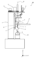
- FIG. 1 It is a schematic diagram for demonstrating the honing processing method which concerns on embodiment, and is the figure which shows the state which inserted the honing tool into the processing hole of a work. It is sectional drawing which shows a part of the honing processing apparatus which concerns on Comparative Example 1. FIG. It is sectional drawing which shows a part of the honing processing apparatus which concerns on Comparative Example 2. FIG. It is a perspective view which shows a part of the honing tool which concerns on a modification. It is a side view which shows a part of the honing tool which concerns on a modification. It is a perspective view which shows a part of the honing tool which concerns on a modification.
- the honing tool according to the present embodiment is attached to the tip of the rotating spindle of the honing machine and honing the inner surface of the machined hole of the work.
- the honing tool includes a grinding portion having a grinding surface, a tool body, an outer cylinder, and an expansion rod.
- the tool body has a long tubular first part and a long tubular second part that is continuous with one end of the first part and has a window part through which the grinding part is inserted. It is tubular and has a third portion that is continuous with the other end of the first portion and is fixed to the tip of the rotating spindle.
- the outer cylinder has a long tubular shape and is fitted onto the first portion of the tool body.
- the expansion rod is rod-shaped and is inserted inside the tool body.
- at least one of the tool body and the outer cylinder is a discharge portion that discharges the grinding liquid flowing into the gap formed between the outer wall of the tool body and the inner wall of the outer cylinder to the outside of the second portion of the tool body.
- the outer diameter dimension of the outer cylinder is smaller than the outer diameter dimension of the second portion described above.
- the honing machine 100 processes the inner wall Wa of the machined hole Wh of the work W, and includes a honing tool 1, a rotating spindle 2, and a rotation driving unit 5.
- a reciprocating drive unit 4, an extended drive unit 6, a machine body 3, a connecting member 10, and a grinding fluid supply unit 9 are provided.
- the work W is arranged in a posture in which the central axis J10 of the machined hole Wh and the central axis J0 of the rotating spindle 2 coincide with each other.
- the rotary spindle 2 is supported by the machine body 3 and is rotatable around the central axis J0.
- the rotation drive unit 5 rotates the rotation spindle 2.
- the reciprocating drive unit 4 reciprocates the rotary spindle 2 in the vertical direction.
- the expansion drive unit 6 expands and moves the grinding unit 13 via the expansion rod 11 described later.
- the machine body 3 supports the rotation drive unit 5, the reciprocating drive unit 4, and the expansion drive unit 6 together with the rotation spindle 2.
- the grinding fluid supply unit 9 has a grinding fluid supply path 91a.
- the connecting member 10 is for connecting the grinding fluid supply unit 9 and the holding member 18 described later, and is for partially supplying the grinding fluid supplied from the grinding fluid supply unit 9 to the holding member 18.
- the grinding fluid supply unit 9 supplies the grinding fluid to the holding member 18 through the grinding fluid supply paths 91a and 10a. It is assumed that the Z-axis direction in FIG. 2 coincides with the tubular axis J1 direction of the tool body 12 and the central axis J2 direction of the expansion rod 11, which will be described later.
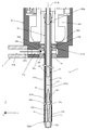
- the honing tool 1 includes a grinding portion 13, a tool main body 12, an outer cylinder 17, an expansion rod 11, and a holding member 18.
- the upper end side of the tool body 12 is attached to the rotary spindle 2 via an adapter (not shown).
- the grinding unit 13 has two long grindstones 131 and a long grindstone base 132 to which the grindstones 131 are combined.
- the grindstone 131 is, for example, a fine diamond abrasive grain, a CBN abrasive grain, or the like bonded by a bonding material.
- the grindstone base 132 is formed of, for example, a metal such as aluminum or steel or a resin material such as an epoxy resin or a phenol resin.
- the grinding unit 13 is a part of the grindstone 131, and the grinding surface 13a along the inner wall Wa of the machined hole Wh of the work W and the grindstone base 132 provided on the opposite side of the grinding surface 13a and inclined with respect to the grinding surface 13a. It has a first tapered surface 13b which is a part of the above, and a recessed portion 13c which prevents the grindstone bases 132 from interfering with each other.
- the tool body 12 has a long tubular first portion 121, a long tubular second portion 122 provided with a slit-shaped window portion 122a through which the grinding portion 13 is inserted, and a long tubular portion 122. It has a tubular shape and a third portion 123 fixed to the tip end portion of the rotating spindle 2, that is, the end portion on the ⁇ Z direction side.
- the tubular shafts of the first portion 121, the second portion 122, and the third portion 123 each coincide with the tubular shaft J1 of the entire tool body 12.
- the second part 122 is continuous with one end of the first part 121 on the ⁇ Z direction side
- the third part 123 is continuous with the other end of the first part 121 on the + Z direction side.
- a flat portion 121a extending along the longitudinal direction of the first portion 121 is formed on the outer wall of the first portion 121.
- a guide pin 201 for preventing the expansion rod 11 from rotating with respect to the tool body 12 and restricting the movement of the expansion rod 11 in the Z-axis direction is inserted at the end of the third portion 123 on the + Z direction side.
- a through hole 123a is provided.
- the through holes 123a are provided at two locations facing each other with the tubular shaft of the third portion 123 at the end on the + Z direction side of the third portion 123.
- the expansion rod 11 is provided with a regulation hole (not shown) penetrating in a direction orthogonal to the Z-axis direction.
- the guide pin 201 is provided so as to penetrate one of the through holes 123a provided at two locations of the third portion 123, the regulation hole of the expansion rod 11, and the other through hole 123a.
- the movement range of the expansion rod 11 in the Z-axis direction is limited to the range in which the guide pin 201 can move in the regulation hole.
- the grinding portion 13 is arranged so that the first tapered surface 13b side is arranged inside the tool main body 12 in a posture in which the first tapered surface 13b approaches the cylinder axis J1 toward the ⁇ Z direction side. It is inserted through the window portion 122a of the second portion 122.
- a step portion 12f for restricting the movement range of the expansion rod 11 in the + Z direction may be provided inside the tool body 12.
- an elongated groove 121c is formed at the end of the first portion 121 on the ⁇ Z direction side.
- the groove 121c is a first groove extending from the flat portion 121a to the edge of the first portion 121 on the ⁇ Z direction side.
- a groove 122c is formed on the first portion 121 side of the second portion 122, that is, on the + Z direction side.
- the groove 122c is a second groove that communicates with the groove 121c and the window portion 122a.
- a groove 122d extending in the ⁇ Z direction from the edge of the second portion 122 on the + Z direction side is formed.
- the end portion of the second portion 122 on the ⁇ Z direction side is reduced in diameter toward the ⁇ Z direction.
- the expansion rod 11 has a long rod shape and is inserted inside the tool body 12. Further, the expansion rod 11 has a second tapered surface 11a that is inclined so as to approach the central axis J2 along the longitudinal direction toward the ⁇ Z direction side.
- the expansion rod 11 is connected to the above-mentioned expansion drive unit 6 and is moved along the Z-axis direction by the expansion drive unit 6.
- Four second tapered surfaces 11a are provided around the central axis J2 of the expansion rod 11.
- the expansion rod 11 may have a movement limiting portion 11c for limiting the movement range of the expansion rod 11 in the + Z direction while being inserted inside the tool body 12.
- the expansion rod 11 is inserted into the tool body 12 so that the movement limiting portion 11c is located inside the tool body 12 in the ⁇ Z direction with respect to the step portion 12f of the tool body 12. Then, for example, when the expansion rod 11 moves in the + Z direction and the end portion of the movement limiting portion 11c on the + Z direction side comes into contact with the step portion 12f, the movement of the expansion rod 11 in the + Z direction is restricted. Then, as shown in FIG. 2, the expansion rod 11 is inserted inside the tool body 12 so that the second tapered surface 11a comes into surface contact with the first tapered surface 13b of the grinding portion 13. Here, when the expansion rod 11 moves in the ⁇ Z direction, the grinding portion 13 is pushed outward.
- the grinding portion 13 is brought into contact with the tool body because the first tapered surface 13b and the second tapered surface 11a are in surface contact with each other, for example, with lubricating oil interposed therebetween. It is pulled back to the inside of 12.
- the second tapered surfaces 11a are provided at equal intervals in the circumferential direction around the central axis J2
- the present invention is not limited to this, and the second tapered surfaces 11a may not be at equal intervals.
- the outer cylinder 17 has a long cylindrical shape and is externally fitted to the first portion 121 of the tool body 12. Then, as shown in FIG. 2, a gap S1 in which the grinding fluid flows from the grinding fluid supply portion 9 is formed between the flat portion 121a of the outer wall of the tool body 12 and the inner wall of the outer cylinder 17.
- the grinding fluid that has flowed into the gap S1 between the flat portion 121a of the tool body 12 and the inner wall of the outer cylinder 17 flows into the groove 122c through the groove 121c.
- the grinding fluid that has flowed into the groove 122c is discharged to the outside of the second portion 122 of the tool body 12, as shown by the arrow AR11 in FIG. 5B.
- the grooves 121c and 122c each constitute a discharge portion for discharging the grinding fluid flowing into the gap S1 between the flat portion 121a of the tool body 12 and the outer cylinder 17 to the outside of the second portion 122 of the tool body 12. doing.
- the outer cylinder 17 has a circular inflow hole 17b in a plan view for allowing the grinding fluid to flow into the inside of the outer cylinder 17.
- the outer cylinder 17 has a notch 17a formed at one end of the tool body 12 of the outer cylinder 17 on the second portion 122 side, that is, on the ⁇ Z direction side.
- the cutout portion 17a constitutes a discharge portion that discharges the grinding fluid that has flowed into the gap between the tool body 12 and the outer cylinder 17 to a region other than the second portion 122. To do.
- a part of the grinding fluid discharged from the notch 17a is also supplied to the outside of the second portion 122 through the groove 122d formed in the outer wall of the second portion 122 of the tool body 12.
- the outer diameter dimension of the outer cylinder 17, that is, the diameter D2 of the outer cylinder 17, is the outer diameter dimension of the second portion 122. That is, it is smaller than the diameter D1 of the second portion 122.
- the holding member 18 is detachably attached to the tool body 12 and holds the other end of the outer cylinder 17 on the side opposite to the second portion 122 side, that is, on the + Z direction side.
- the holding member 18 has a cylindrical shape, and a recess 18c is formed in the outer wall of the central portion in the tubular axis direction. Further, a plurality of through holes 18a penetrating from the bottom of the recess 18c of the holding member 18 to the inside of the holding member 18 are provided. Further, as shown in FIG. 2, an annular receiving groove 18f for communicating with all of the plurality of through holes 18a and receiving the grinding fluid flowing out from the through holes 18a is formed on the inner wall of the holding member 18.
- a screw hole 18b into which a screw 202 for fixing the holding member 18 to the tool body 12 is screwed is provided at the end of the holding member 18 on the + Z direction side.
- the tip of the screw 202 is fitted into the recess 121b.
- the holding member 18 has a posture in which the inflow hole 17b of the outer cylinder 17 and the receiving groove 18f formed inside the holding member 18 overlap each other in the radial direction of the tool body 12 and the outer cylinder 17, and the tool main body is screwed 202. It is fixed at 12.
- a step portion 18d into which an end portion of the outer cylinder 17 on the + Z direction side is fitted is provided inside the holding member 18.
- the grinding fluid supply unit 9 passes through the through hole 18a of the holding member 18 and the inflow hole 17b of the outer cylinder 17 from the grinding fluid supply passage 91a to the outer wall of the tool body 12 and the inner wall of the outer cylinder 17.
- the grinding fluid is allowed to flow into the gap S1 between the two.
- FIGS. 5B, 7A, and 7B Next, the honing processing method using the honing tool 1 according to the present embodiment will be described with reference to FIGS. 5B, 7A, and 7B.
- a step of bringing the tool 1 closer to the machined hole Wh of the work W is performed. Note that in FIGS. 7A and 7B, the groove 122c and the notch 17a are not shown.
- FIG. 7A and 7B the groove 122c and the notch 17a are not shown.
- the grinding fluid is continuously discharged from the groove 122c of the second portion 122 and the notch 17a of the outer cylinder 17, and the second portion 122 and the outer cylinder 17 of the tool body 12 continue to be discharged.
- One end on the ⁇ Z direction side is arranged inside the machined hole Wh of the work W, and a step of supplying the grinding fluid to the inner wall Wa of the machined hole Wh is performed. In this step, by reciprocating the second portion 122 in the direction of the central axis of the machined hole Wh of the work W, the grinding fluid can be sufficiently supplied to the entire inner wall Wa of the machined hole Wh of the work W.
- the honing tool 8001 according to Comparative Example 1 rotatably supports the grinding portion 13, the tool body 8012, the expansion rod 8011, and the tool body 8012 around the central axis along the longitudinal direction thereof.
- the support member 8018 is provided.
- the support member 8018 has an inflow hole 8012a communicating with the grinding liquid supply path 8091a of the grinding fluid supply unit 8009, and an discharge path 8012b for discharging the grinding liquid flowing in from the inflow hole 8012a to the grinding unit 13 side.
- the grinding liquid that has flowed into the discharge path 8018b from the grinding fluid supply path 8091a of the grinding fluid supply unit 8009 through the inflow hole 8018a is directed from the support member 8018 toward the work W as shown by the arrow AR82. It is discharged.
- the honing tool 8001 according to Comparative Example 1 is used by rotating it around a central axis along the longitudinal direction, the grinding fluid scatters due to centrifugal force, and the grinding fluid is applied to the machined holes Wh of the work W. It may not be possible to reach it sufficiently.
- the grinding portion 13, the tool body 9012, the expansion rod 9011, and the tool body 9012 can be rotated around the central axis along the longitudinal direction.
- a support member 9018 for supporting is provided.
- the tool body 9012 is provided with an inflow hole 9012a that communicates with the grinding fluid supply path 9091a of the grinding fluid supply unit 9009. Then, as shown by the arrow AR91, the grinding liquid that has flowed into the discharge path 8012b from the grinding fluid supply path 9091a of the grinding fluid supply unit 9009 through the inflow hole 9012a is ground through the inside of the tool body 9012 as shown by the arrow AR92.
- the portion 13 is discharged to a region opposite to the grinding surface side.
- the grinding fluid can be supplied to the vicinity of the grinding portion 13 without being scattered.
- the supply pressure of the grinding fluid causes the grinding unit 13 to be directed in the radial direction of the tool body 9012. Force acts. Therefore, it is necessary to provide the tool body 9012 with a structure for pressing the grinding portion 13 from the outside of the tool body 12 so that the grinding portion 13 does not separate from the tool body 9012, which may make it difficult to reduce the diameter of the tool body 9012.
- the grinding fluid is supplied to the outside of the second portion 122 through the groove 122c of the tool main body 12.
- the radial force of the tool body 12 is suppressed from acting on the grinding portion 13, so that the diameter of the tool body 12 can be reduced.
- the tool body 12 flows into the gap S1 formed between the flat portion 121a of the tool body 12 and the inner wall of the outer cylinder 17.
- the diameter D2 of the outer cylinder 17 is smaller than the diameter D1 of the second portion 122.
- the gap S1 formed between the outer wall of the tool body 12 and the outer cylinder 17 functions as a grinding fluid supply path for supplying the grinding fluid to the outside of the second portion 122 of the tool body 12, so that the honing tool is used.
- the outer diameter of 1 can be reduced, and the grinding fluid can be supplied to the gap formed between the machined hole Wh and the honing tool 1 without reducing the strength of the honing tool 1.
- the honing tool 1 in a state where the grinding fluid is continuously discharged from the groove 122c of the tool body 12, the second portion 122 of the tool body 12 and the outer cylinder 17 on the ⁇ Z direction side.
- One end of the work W can be arranged inside the machined hole Wh of the work W to supply the grinding fluid to the inner wall Wa of the machined hole Wh. Therefore, a sufficient amount of grinding liquid can be supplied to the inside of the machined hole Wh of the work W.
- the second portion 122 of the tool body 12 can be arranged at the entire position facing the machined hole Wh of the work W, the grinding portion 13 can be brought into contact with the whole of the machined hole Wh in the central axis direction. .. Therefore, the machining accuracy of the machined hole Wh can be improved.
- the honing tool 1 has a groove 121c formed at one end of the second portion 122 of the tool main body 12 on the ⁇ Z direction side, and the groove 122c is the second portion 122 of the second portion 122. It is formed on the + Z direction side and communicates with the groove 121c and the window portion 122a of the second portion 122.
- the grinding fluid that has flowed into the gap S1 between the flat portion 121a of the tool body 12 and the inner wall of the outer cylinder 17 can be efficiently supplied to the groove 122c through the groove 122c. Therefore, there is an advantage that a sufficient amount of grinding liquid can be easily supplied to the inside of the machined hole Wh of the work W.
- the outer cylinder 17 according to the present embodiment has a notch 17a formed at one end on the ⁇ Z direction side thereof.
- the outer cylinder 17 has an inflow hole 17b for allowing the grinding fluid to flow into the inner cylinder 17.
- the grinding fluid can be efficiently flowed into the gap S1 between the flat portion 121a of the tool body 12 and the inner wall of the outer cylinder 17, so that the grinding fluid can be efficiently flowed into the groove 122c of the tool body 12 or the notch 17a of the outer cylinder 17. A sufficient amount of grinding fluid can be discharged.
- the honing tool 1 includes a holding member 18 that is detachably attached to the tool body 12 and holds the end of the outer cylinder 17 on the + Z direction side.
- the outer cylinder 17 can be separated from the tool main body 12 simply by removing the holding member 18 from the tool main body 12, so that there is an advantage that the outer cylinder 17 can be easily replaced.
- the grinding unit 2013 may have one long grindstone 131 and a long grindstone base 132 to which the grindstone 131 is bonded.
- the same components as those of the honing tool 1 according to the embodiment are designated by the same reference numerals as those in FIGS. 5B and 6. In this case, as shown by the arrow AR21 in FIG.
- the grinding fluid discharged from the groove 122c to the window portion 122a is efficiently moved to the region adjacent to the region inside the window portion 122a in the direction orthogonal to the cylinder axis J1 of the tool body 12.
- Well supplied. According to this configuration, a sufficient amount of grinding fluid can be supplied over the entire vicinity of the grindstone 131.
- the shape of the second portion 122 is not limited to this.
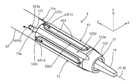
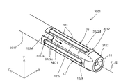
- the honing tool 3001 including the tool body 3012 and the outer cylinder 3017 as shown in FIGS. 10A and 10B may be used.
- FIGS. 10A and 10B the same components as those of the honing tool 1 according to the embodiment are designated by the same reference numerals as those in FIGS. 5B and 6.
- a groove 3122d extending from the edge on the + Z direction side toward the ⁇ Z direction is formed.
- a slit 3122c extending along the groove 3122d is formed at the end of the groove 3122d on the ⁇ Z direction side from the edge of the second portion 3122 on the + Z direction side.
- the outer cylinder 3017 has an extension piece 3017a extending from the end portion on the ⁇ Z direction side to the ⁇ Z direction side.
- the outer cylinder 3017 is arranged so that the extension piece 3017a covers a part of the slit 3122c of the second portion 3122.
- the end portion of the second portion 3122 on the ⁇ Z direction side is reduced in diameter toward the ⁇ Z direction. Then, as shown by the arrow AR31 in FIG.
- the grinding fluid discharged from the gap between the outer wall of the tool body 3012 and the inner wall of the outer cylinder 3017 to the inside of the second portion 3122 is discharged into the slit 3122c and the extension piece 3017a. It flows out to the groove 3122d from the gap between the two.
- the diameter D2 of the outer cylinder 3017 is smaller than the diameter D1 of the second portion 3122 of the tool body 3012 when viewed from the cylinder axis J1 direction of the tool body 3012.
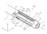
- the honing tool 4001 including the tool body 4012 and the outer cylinder 4017 as shown in FIGS. 11A and 11B may be used.
- the same components as those of the honing tool 1 according to the embodiment are designated by the same reference numerals as those in FIGS. 5B and 6.
- a groove 122d extending in the ⁇ Z direction from the edge of the second portion 4122 on the + Z direction side is formed at a portion of the outer wall of the second portion 4122 adjacent to the window portion 4122a.
- a recess 4122e cut out along the cylinder axis J1 direction of the tool body 4012 is formed between the window portion 4122a and the groove 122d on the outer wall of the second portion 4122. Further, the end portion of the second portion 4122 on the ⁇ Z direction side is reduced in diameter toward the ⁇ Z direction. As shown by the arrow AR41 in FIG. 11A, the grinding fluid that has flowed into the gap between the outer wall of the tool body 4012 and the inner wall of the outer cylinder 4017 passes through the gap between the groove 122d of the second portion 4122 and the outer cylinder 4017. It is discharged into the groove 122d.
- the grinding fluid discharged into the groove 122d of the second portion 4122 flows out to the window portion 4122a side through the recess 4122e as shown by the arrow AR42.
- the diameter D2 of the outer cylinder 4017 is smaller than the diameter D1 of the second portion 4122 of the tool body 4012 when viewed from the cylinder axis J1 direction of the tool body 4012.
- the honing tool 5001 including the tool body 5012 and the outer cylinder 4017 as shown in FIGS. 12A and 12B may be used.
- FIGS. 10A and 10B the same components as those of the honing tool 1 according to the embodiment are designated by the same reference numerals as those in FIGS. 5B and 6.
- FIGS. 12A and 12B the same components as those of the honing tool 4001 described with reference to FIGS. 10A and 10B described above are designated by the same reference numerals as those in FIGS. 11A and 11B.
- three through holes 5122f are formed along the longitudinal direction of the second portion 5122.
- the end portion of the second portion 5122 on the ⁇ Z direction side has a reduced diameter toward the ⁇ Z direction, and four grooves 5122g may be formed on the outer wall.
- the grinding fluid that has flowed into the inside of the second portion 5122 through the gap between the outer wall of the tool body 4012 and the inner wall of the outer cylinder 4017 is penetrated into the second portion 5122. It is discharged to the outside of the second portion 5122 through the through hole 5122f.
- the diameter D2 of the outer cylinder 4017 is smaller than the diameter D1 of the second portion 4122 of the tool body 5012 when viewed from the cylinder axis J1 direction of the tool body 5012.
- the expansion rod 11 has a long rod shape and has a second tapered surface 11a that is inclined so as to approach the central axis J2 along the longitudinal direction toward the tip end side, that is, the ⁇ Z direction side.
- the shape of the expansion rod is not limited to this. For example, even if the expansion rod has a long rod shape and has a second tapered surface that is inclined so as to approach the central axis J2 along the longitudinal direction toward the base end side, that is, the + Z direction side. Good.
- the present invention is suitable as a honing tool mounted on a honing machine that performs honing on a workpiece having a relatively small diameter.
- Honing tool 2 Rotation spindle 3: Machine body 4: Reciprocating drive unit 5: Rotation drive unit, 6: Expansion drive unit, 9: Grinding liquid supply unit, 10: Connection Members, 10a, 91a: Grinding liquid supply path, 11: Expansion rod, 11a: Second tapered surface, 11c: Movement control part, 12,3012,401,5012: Tool body, 12f, 18d: Step part, 13,2013 : Grinding part, 13a: Grinding surface, 13b: First tapered surface, 13c: Recessed part, 17,3017,4017: Outer cylinder, 17a: Notch, 17b: Inflow hole, 18: Holding member, 18a, 123a, 5122f : Through hole, 18b: Screw hole, 18c, 4122e: Recessed, 18f: Receiving groove, 100: Honing machine, 121: First part, 121a: Flat part, 121b: Recessed, 121c, 122c, 122d, 3122d
Landscapes
- Engineering & Computer Science (AREA)
- Mechanical Engineering (AREA)
- Physics & Mathematics (AREA)
- Geometry (AREA)
- Finish Polishing, Edge Sharpening, And Grinding By Specific Grinding Devices (AREA)
Abstract
Description
ホーニング加工装置の回転主軸の先端部に取り付けられ、ワークの加工孔の内面をホーニング加工するホーニングツールであって、
研削面を有する研削部と、
長尺の筒状の第1部位と、長尺の筒状であり前記第1部位の一端部に連続するとともに前記研削部が挿通される窓部が設けられた第2部位と、長尺の筒状であり前記第1部位の他端部に連続するとともに前記回転主軸の先端部に固定される第3部位と、を有するツール本体と、
長尺の筒状であり、前記ツール本体の前記第1部位に外嵌される外筒と、
棒状であり前記ツール本体の内側に挿通される拡張ロッドと、を備え、
前記ツール本体と前記外筒との少なくとも一方は、前記ツール本体の外壁と前記外筒の内壁との間に形成された隙間に流入される研削液を前記第2部位の外側へ排出する排出部を有し、
前記外筒の外径寸法は、前記第2部位の外径寸法以下である。 In order to achieve the above object, the honing tool according to the present invention is
A honing tool that is attached to the tip of the rotating spindle of a honing machine and honing the inner surface of the machined hole of the work.
A grinding part with a ground surface and
A long tubular first part, a long tubular second part that is continuous with one end of the first part and has a window part through which the grinding part is inserted, and a long part. A tool body having a tubular shape, a third portion continuous with the other end of the first portion and fixed to the tip of the rotating spindle, and a tool body.
An outer cylinder that has a long tubular shape and is externally fitted to the first portion of the tool body,
It is equipped with an expansion rod that is rod-shaped and is inserted inside the tool body.
At least one of the tool body and the outer cylinder is a discharge unit that discharges the grinding liquid flowing into the gap formed between the outer wall of the tool body and the inner wall of the outer cylinder to the outside of the second portion. Have,
The outer diameter dimension of the outer cylinder is equal to or less than the outer diameter dimension of the second portion.
Claims (6)
- ホーニング加工装置の回転主軸の先端部に取り付けられ、ワークの加工孔の内面をホーニング加工するホーニングツールであって、
研削面を有する研削部と、
長尺の筒状の第1部位と、長尺の筒状であり前記第1部位の一端部に連続するとともに前記研削部が挿通される窓部が設けられた第2部位と、長尺の筒状であり前記第1部位の他端部に連続するとともに前記回転主軸の先端部に固定される第3部位と、を有するツール本体と、
長尺の筒状であり、前記ツール本体の前記第1部位に外嵌される外筒と、
棒状であり前記ツール本体の内側に挿通される拡張ロッドと、を備え、
前記ツール本体と前記外筒との少なくとも一方は、前記ツール本体の外壁と前記外筒の内壁との間に形成された隙間に流入される研削液を前記第2部位の外側へ排出する排出部を有し、
前記外筒の外径寸法は、前記第2部位の外径寸法以下である、
ホーニングツール。 A honing tool that is attached to the tip of the rotating spindle of a honing machine and honing the inner surface of the machined hole of the work.
A grinding part with a ground surface and
A long tubular first part, a long tubular second part that is continuous with one end of the first part and has a window part through which the grinding part is inserted, and a long part. A tool body having a tubular shape, a third portion continuous with the other end of the first portion and fixed to the tip of the rotating spindle, and a tool body.
An outer cylinder that has a long tubular shape and is externally fitted to the first portion of the tool body,
It is equipped with an expansion rod that is rod-shaped and is inserted inside the tool body.
At least one of the tool body and the outer cylinder is a discharge unit that discharges the grinding liquid flowing into the gap formed between the outer wall of the tool body and the inner wall of the outer cylinder to the outside of the second portion. Have,
The outer diameter dimension of the outer cylinder is equal to or less than the outer diameter dimension of the second portion.
Honing tool. - 前記排出部は、前記第1部位における前記第2部位側の一端部に形成された第1溝と、前記第2部位の前記第1部位側に形成され前記第1溝と前記窓部とに連通する第2溝と、を有する、
請求項1に記載のホーニングツール。 The discharge portion is formed in a first groove formed at one end of the first portion on the side of the second portion, and the first groove formed on the side of the first portion of the second portion and the window portion. It has a second groove that communicates with it.
The honing tool according to claim 1. - 前記排出部は、前記外筒の前記第2部位側の一端部に形成された切欠部を有する、
請求項1または2に記載のホーニングツール。 The discharge portion has a notch formed at one end of the outer cylinder on the second portion side.
The honing tool according to claim 1 or 2. - 前記外筒は、前記外筒の内側へ前記研削液を流入させる流入孔を有する、
請求項1から3のいずれか1項に記載のホーニングツール。 The outer cylinder has an inflow hole for allowing the grinding fluid to flow inside the outer cylinder.
The honing tool according to any one of claims 1 to 3. - 前記ツール本体に着脱自在に装着され、前記外筒の前記第2部位側とは反対側の他端部を保持する保持部材を更に備える、
請求項1から4のいずれか1項に記載のホーニングツール。 A holding member that is detachably attached to the tool body and holds the other end of the outer cylinder on the side opposite to the second portion side is further provided.
The honing tool according to any one of claims 1 to 4. - 研削面を有する研削部と、長尺の筒状の第1部位と長尺の筒状であり前記第1部位の一端部に連続するとともに前記研削部が挿通される窓部が設けられた第2部位と長尺の筒状であり前記第1部位の他端部に連続するとともにホーニング加工装置の回転主軸の先端部に固定される第3部位とを有するツール本体と、長尺の筒状であり、前記ツール本体の前記第1部位に外嵌される外筒と、棒状であり前記ツール本体の内側に挿通される拡張ロッドと、を備え、前記ツール本体と前記外筒との少なくとも一方は、前記ツール本体の外壁と前記外筒の内壁との間に形成された隙間に流入される研削液を前記第2部位の外側へ排出する排出部を有し、前記外筒の外径寸法が、前記第2部位の外径寸法以下であるホーニングツールを用いたホーニング加工方法であって、
前記排出部から前記研削液が排出され続けている状態で、前記第2部位および前記外筒の前記第1部位側の一端部を、ワークの加工孔の内側に配置し前記加工孔の内壁へ前記研削液を供給する工程を含む、
ホーニング加工方法。 A ground portion having a ground surface, a long tubular first portion, and a long tubular first portion provided with a window portion continuous with one end of the first portion and through which the ground portion is inserted. A tool body having two parts and a third part that is long and continuous with the other end of the first part and is fixed to the tip of the rotating spindle of the honing machine, and a long tubular shape. It is provided with an outer cylinder that is externally fitted to the first portion of the tool body and an expansion rod that is rod-shaped and is inserted into the inside of the tool body, and at least one of the tool body and the outer cylinder. Has a discharge portion for discharging the grinding liquid flowing into the gap formed between the outer wall of the tool body and the inner wall of the outer cylinder to the outside of the second portion, and has an outer diameter dimension of the outer cylinder. Is a honing processing method using a honing tool having a size equal to or less than the outer diameter of the second part.
In a state where the grinding fluid is continuously discharged from the discharging portion, one end portion of the second portion and the outer cylinder on the first portion side is arranged inside the machined hole of the work and reaches the inner wall of the machined hole. Including the step of supplying the grinding fluid
Honing processing method.
Priority Applications (3)
| Application Number | Priority Date | Filing Date | Title |
|---|---|---|---|
| KR1020227003866A KR20220025106A (en) | 2019-07-26 | 2020-06-22 | Honing tools and honing methods |
| CN202080053892.5A CN114222646A (en) | 2019-07-26 | 2020-06-22 | Honing tool and honing method |
| JP2021536658A JP7244650B2 (en) | 2019-07-26 | 2020-06-22 | Honing tool and honing method |
Applications Claiming Priority (2)
| Application Number | Priority Date | Filing Date | Title |
|---|---|---|---|
| JP2019137472 | 2019-07-26 | ||
| JP2019-137472 | 2019-07-26 |
Publications (1)
| Publication Number | Publication Date |
|---|---|
| WO2021019956A1 true WO2021019956A1 (en) | 2021-02-04 |
Family
ID=74229041
Family Applications (1)
| Application Number | Title | Priority Date | Filing Date |
|---|---|---|---|
| PCT/JP2020/024381 WO2021019956A1 (en) | 2019-07-26 | 2020-06-22 | Honing tool and honing machining method |
Country Status (4)
| Country | Link |
|---|---|
| JP (1) | JP7244650B2 (en) |
| KR (1) | KR20220025106A (en) |
| CN (1) | CN114222646A (en) |
| WO (1) | WO2021019956A1 (en) |
Families Citing this family (1)
| Publication number | Priority date | Publication date | Assignee | Title |
|---|---|---|---|---|
| KR102622025B1 (en) * | 2023-10-19 | 2024-01-10 | 주식회사 영테크 | Cutting oil supply device for honing machine |
Citations (4)
| Publication number | Priority date | Publication date | Assignee | Title |
|---|---|---|---|---|
| JPS5648460U (en) * | 1979-09-21 | 1981-04-30 | ||
| JPH01177926A (en) * | 1987-12-30 | 1989-07-14 | Yoshino Seiki:Kk | Manufacture of core drill |
| JP2012086516A (en) * | 2010-10-22 | 2012-05-10 | Hitachi Koki Co Ltd | Drill bit |
| JP2012187682A (en) * | 2011-03-11 | 2012-10-04 | Honda Motor Co Ltd | Grinding tool for honing |
Family Cites Families (12)
| Publication number | Priority date | Publication date | Assignee | Title |
|---|---|---|---|---|
| JPH074759B2 (en) | 1988-10-14 | 1995-01-25 | 大昭和精機株式会社 | Honing head |
| JPH02106268A (en) * | 1988-10-14 | 1990-04-18 | Daishowa Seiki Co Ltd | Honing head |
| JPH09300206A (en) * | 1996-05-10 | 1997-11-25 | Nissan Motor Co Ltd | Cooling method and device for honing work and honing head |
| US6679766B2 (en) * | 2002-04-16 | 2004-01-20 | Robert Bosch Gmbh | Diamond sleeve honing tool |
| JP2006043818A (en) * | 2004-08-04 | 2006-02-16 | Houkou:Kk | Honing machine and honing method |
| JP4533866B2 (en) * | 2006-05-29 | 2010-09-01 | 本田技研工業株式会社 | Composite machine tool and cylinder block bore boring method using the composite machine tool |
| CN101905440B (en) * | 2009-09-28 | 2012-01-11 | 苏州信能精密机械有限公司 | High-precision high-efficiency three-position numerical control honing method and device |
| JP5648460B2 (en) | 2010-12-15 | 2015-01-07 | セイコーエプソン株式会社 | Storage device, integrated circuit device, and electronic apparatus |
| JP2012183614A (en) * | 2011-03-07 | 2012-09-27 | Fuji Heavy Ind Ltd | Honing apparatus |
| CN106181743B (en) * | 2016-08-01 | 2018-01-23 | 中北大学 | Radial ultrasonic Honing process device |
| CN206123414U (en) * | 2016-08-31 | 2017-04-26 | 德清勤龙磨床制造有限公司 | Honing machine |
| CN208913843U (en) * | 2018-09-30 | 2019-05-31 | 常州凯瑞莱精密工具有限公司 | It is a kind of for finishing the hone of inner hole |
-
2020
- 2020-06-22 WO PCT/JP2020/024381 patent/WO2021019956A1/en active Application Filing
- 2020-06-22 KR KR1020227003866A patent/KR20220025106A/en active IP Right Grant
- 2020-06-22 CN CN202080053892.5A patent/CN114222646A/en active Pending
- 2020-06-22 JP JP2021536658A patent/JP7244650B2/en active Active
Patent Citations (4)
| Publication number | Priority date | Publication date | Assignee | Title |
|---|---|---|---|---|
| JPS5648460U (en) * | 1979-09-21 | 1981-04-30 | ||
| JPH01177926A (en) * | 1987-12-30 | 1989-07-14 | Yoshino Seiki:Kk | Manufacture of core drill |
| JP2012086516A (en) * | 2010-10-22 | 2012-05-10 | Hitachi Koki Co Ltd | Drill bit |
| JP2012187682A (en) * | 2011-03-11 | 2012-10-04 | Honda Motor Co Ltd | Grinding tool for honing |
Also Published As
| Publication number | Publication date |
|---|---|
| KR20220025106A (en) | 2022-03-03 |
| JPWO2021019956A1 (en) | 2021-02-04 |
| CN114222646A (en) | 2022-03-22 |
| JP7244650B2 (en) | 2023-03-22 |
Similar Documents
| Publication | Publication Date | Title |
|---|---|---|
| US6270295B1 (en) | Tool with selectively biased member and method of using the same | |
| US6536998B2 (en) | Selectively biased tool and methods of using the same | |
| JP4999560B2 (en) | Wheel spindle device for grinding machine | |
| KR20130069589A (en) | Drill head for a deep hole drilling tool for bta deep hole drilling, and deep hole drilling tool | |
| CN106457429B (en) | Diamond electroplating for the processing of advanced hardened ceramic grinds end mill(ing) cutter | |
| KR20110113745A (en) | Drill system, drill inserts and methods | |
| KR20140005946A (en) | Drilling tool and method for producing drill holes | |
| WO2010114076A1 (en) | Bore working tool | |
| WO2021019956A1 (en) | Honing tool and honing machining method | |
| US6585571B2 (en) | Distal end honing device | |
| JPH0347817Y2 (en) | ||
| US20140141703A1 (en) | Single and tandem honing devices | |
| JP5346651B2 (en) | Assembly method of internal grinding tool | |
| JP4966717B2 (en) | Drilling tool | |
| JP4681376B2 (en) | Grinding method for workpiece grooves | |
| JP2009083078A (en) | Reamer | |
| KR101336661B1 (en) | Continual machining apparatus | |
| Mandole et al. | Manufacturing of portable vertical honing machine for small diameter bores | |
| JP2009297803A (en) | Boring tool | |
| JPH079312A (en) | Method and tool for drilling small-diameter deep hole, and finishing machine having the tool | |
| JP2021171827A (en) | Tool holder, processing machine including tool holder and method for processing scroll compressor component using tool holder | |
| JP2004181607A (en) | Working method of bore inner surface of engine block | |
| JP2023028875A (en) | Processing device and processing method | |
| JP2004345064A (en) | Diamond tool for machining brittle material, and machining method using the same | |
| JP2013141736A (en) | Spherical surface grinding device and grinding method |
Legal Events
| Date | Code | Title | Description |
|---|---|---|---|
| 121 | Ep: the epo has been informed by wipo that ep was designated in this application |
Ref document number: 20847259 Country of ref document: EP Kind code of ref document: A1 |
|
| ENP | Entry into the national phase |
Ref document number: 2021536658 Country of ref document: JP Kind code of ref document: A |
|
| NENP | Non-entry into the national phase |
Ref country code: DE |
|
| ENP | Entry into the national phase |
Ref document number: 20227003866 Country of ref document: KR Kind code of ref document: A |
|
| 122 | Ep: pct application non-entry in european phase |
Ref document number: 20847259 Country of ref document: EP Kind code of ref document: A1 |