WO2021015262A1 - フロート集合体を管理するシステム - Google Patents
フロート集合体を管理するシステム Download PDFInfo
- Publication number
- WO2021015262A1 WO2021015262A1 PCT/JP2020/028521 JP2020028521W WO2021015262A1 WO 2021015262 A1 WO2021015262 A1 WO 2021015262A1 JP 2020028521 W JP2020028521 W JP 2020028521W WO 2021015262 A1 WO2021015262 A1 WO 2021015262A1
- Authority
- WO
- WIPO (PCT)
- Prior art keywords
- float
- peripheral portion
- detection
- vertical direction
- central portion
- Prior art date
- Legal status (The legal status is an assumption and is not a legal conclusion. Google has not performed a legal analysis and makes no representation as to the accuracy of the status listed.)
- Ceased
Links
Images



Classifications
-
- B—PERFORMING OPERATIONS; TRANSPORTING
- B63—SHIPS OR OTHER WATERBORNE VESSELS; RELATED EQUIPMENT
- B63B—SHIPS OR OTHER WATERBORNE VESSELS; EQUIPMENT FOR SHIPPING
- B63B35/00—Vessels or similar floating structures specially adapted for specific purposes and not otherwise provided for
-
- G—PHYSICS
- G01—MEASURING; TESTING
- G01B—MEASURING LENGTH, THICKNESS OR SIMILAR LINEAR DIMENSIONS; MEASURING ANGLES; MEASURING AREAS; MEASURING IRREGULARITIES OF SURFACES OR CONTOURS
- G01B11/00—Measuring arrangements characterised by the use of optical techniques
-
- G—PHYSICS
- G01—MEASURING; TESTING
- G01C—MEASURING DISTANCES, LEVELS OR BEARINGS; SURVEYING; NAVIGATION; GYROSCOPIC INSTRUMENTS; PHOTOGRAMMETRY OR VIDEOGRAMMETRY
- G01C13/00—Surveying specially adapted to open water, e.g. sea, lake, river or canal
-
- H—ELECTRICITY
- H02—GENERATION; CONVERSION OR DISTRIBUTION OF ELECTRIC POWER
- H02S—GENERATION OF ELECTRIC POWER BY CONVERSION OF INFRARED RADIATION, VISIBLE LIGHT OR ULTRAVIOLET LIGHT, e.g. USING PHOTOVOLTAIC [PV] MODULES
- H02S10/00—PV power plants; Combinations of PV energy systems with other systems for the generation of electric power
- H02S10/40—Mobile PV generator systems
-
- Y—GENERAL TAGGING OF NEW TECHNOLOGICAL DEVELOPMENTS; GENERAL TAGGING OF CROSS-SECTIONAL TECHNOLOGIES SPANNING OVER SEVERAL SECTIONS OF THE IPC; TECHNICAL SUBJECTS COVERED BY FORMER USPC CROSS-REFERENCE ART COLLECTIONS [XRACs] AND DIGESTS
- Y02—TECHNOLOGIES OR APPLICATIONS FOR MITIGATION OR ADAPTATION AGAINST CLIMATE CHANGE
- Y02A—TECHNOLOGIES FOR ADAPTATION TO CLIMATE CHANGE
- Y02A90/00—Technologies having an indirect contribution to adaptation to climate change
- Y02A90/30—Assessment of water resources
-
- Y—GENERAL TAGGING OF NEW TECHNOLOGICAL DEVELOPMENTS; GENERAL TAGGING OF CROSS-SECTIONAL TECHNOLOGIES SPANNING OVER SEVERAL SECTIONS OF THE IPC; TECHNICAL SUBJECTS COVERED BY FORMER USPC CROSS-REFERENCE ART COLLECTIONS [XRACs] AND DIGESTS
- Y02—TECHNOLOGIES OR APPLICATIONS FOR MITIGATION OR ADAPTATION AGAINST CLIMATE CHANGE
- Y02E—REDUCTION OF GREENHOUSE GAS [GHG] EMISSIONS, RELATED TO ENERGY GENERATION, TRANSMISSION OR DISTRIBUTION
- Y02E10/00—Energy generation through renewable energy sources
- Y02E10/50—Photovoltaic [PV] energy
Definitions
- the present invention relates to a system for managing float aggregates.
- a solar panel also called a solar cell panel or a solar cell module
- Solar panels are mainly installed on the roofs, walls, and ground of buildings, but in recent years, they have also been installed on the water of idle ponds and lakes.
- a technique for improving power generation efficiency is known by slowly rotating a float aggregate formed by connecting such floats to the position of the sun. When rotating, a centrally fixed axis of rotation is required to avoid translational movement of the float assembly.
- a method of locking the central part of the float assembly to the bottom of the pond with a wire or the like can be considered, but it is necessary to adjust the length of the wire according to the change in the water level.
- the present invention has been proposed in view of such circumstances, and an object of the present invention is a float aggregate capable of detecting a change in the position of a float aggregate based on a change in water level with a simple configuration and accuracy. Is to provide a management system for.
- the present invention is a system that manages the arrangement of float aggregates arranged on water, and the float aggregates are placed on a central portion whose position in the vertical direction is restricted and on a water surface around the central portion.
- the system includes a peripheral portion arranged so as to float, the system includes a photographing device for photographing the central portion and the peripheral portion, and the central portion based on a change in water level based on image data photographed by the photographing device.
- a system is provided that measures changes in the vertical position of the portion and the peripheral portion.
- the change in the relative position of the central part and the peripheral part of the float aggregate in the vertical direction can be measured by the image data taken by the photographing device, which facilitates the introduction and water pollution. Since it is not affected by, high-precision measurement is possible.
- the imaging device has a fixed position in the vertical direction.
- the central portion is restricted in vertical position by a wire provided so as to go into the water, and the system controls the length of the wire based on the measured change in the position.
- the central portion is provided with a detection panel that serves as a reference when detecting the position in the vertical direction.
- the peripheral portion is provided with a detection pole that serves as a reference when detecting a position in the vertical direction.
- two detection poles are provided in the peripheral portion, and the detection panel and the detection pole are arranged at positions forming a triangle in a plan view.
- the detection panel is configured to be wider in the horizontal direction than the detection pole.
- the detection panel and the detection pole include a light emitting unit.
- FIG. 5A is a diagram showing a state in which the water level of Lake L is at the reference position.
- FIG. 5B is a diagram showing a state in which the water level of Lake L has dropped.
- FIG. 6A is a diagram showing a state in which the water level of Lake L is at the reference position.
- 6B is a diagram showing a state in which the water level of Lake L has risen. It is a figure explaining the light emitting part of the detection pole 22 and the detection panel 23. It is a top view of the management system 1 of the float assembly 2 which concerns on 2nd Embodiment.
- the float aggregate 2 is composed of a peripheral portion 2a and a central portion 2b, and is floated on the lake L.
- Lake L is just an example and may be a pond or a river as long as it is on the water.
- An imaging device 21 and a control device 24 are installed on the land around the lake L.
- each configuration will be described in order.
- the peripheral portion 2a is configured by connecting a plurality of floats 10 to each other.
- the float 10 is manufactured by, for example, blow molding in which a molten tubular parison is sandwiched between a plurality of split dies and inflated, and various thermoplastic resins can be used as the molding material.
- various thermoplastic resins can be used as the molding material.
- polyethylene can be used.
- a polyolefin resin such as polypropylene can be preferably used.
- a passage joint 60 formed as a plastic molded body is used.
- the passage joint 60 is connected to the float 10 on the upper surface of each float 10, and the floats 10 are connected at predetermined intervals in the connecting direction of the passage joint 60.
- connection in the direction orthogonal to the connection direction by the passage joint 60 is performed by connecting the ends of the floats 10.
- dozens of floats 10 forming the peripheral portion 2a are connected.
- a solar panel 50 is installed on some of these floats 10.
- the solar panel 50 is not installed in some of the floats 10 and is used as a passage for maintenance and inspection of the solar panel 50.
- the passage is also used for laying electrical wiring and the like (not shown) from the solar panel 50.
- the peripheral portion 2a is configured to have a rectangular shape as a whole.
- a rotating wire 4 is provided on the float 10 located at the apex portion of the rectangle.
- the rotating wire 4 is configured to be windable by a rotating winch 5 installed on land. That is, the float 10 located at the apex portion can be pulled by winding the rotating wire 4 through the rotating winch 5 and shifting the position thereof.
- the rotation winch 5 has a mechanism for winding the rotation wire 4 and sending out the rotation wire 4.
- an endless winch driven by a drive device (motor) can be adopted.
- tension is generated in the rotating wire 4.
- the peripheral portion 2a is configured to be independently rotatable around the central portion 2b.
- the rotation range may be less than 180 degrees, and is preferably set appropriately according to the size of the water surface of the lake L, the size of the float 10 used, and the number of solar panels 50 installed. Under such a configuration, the peripheral portion 2a is slowly rotated from sunrise to sunset so that the solar panel 50 faces the direction of the sun.
- the peripheral portion 2a is provided with two detection poles 22 that serve as a reference when detecting the height of the peripheral portion 2a in the vertical direction.
- the detection pole 22 has a cylindrical shape as an example, and is installed upright on the float 10 constituting the peripheral portion 2a in the vertical direction. Details of the detection of the position of the peripheral portion 2a using the detection pole 22 will be described later.
- the central portion 2b is composed of one or more floats 10 and a passage joint 60.
- a float having the same shape as the float 10 constituting the peripheral portion 2a may be used, or a float having a different shape may be used.
- the peripheral portion 2a is configured to be rotatable around the central portion 2b, whereas the central portion 2b is a shaft wire with respect to the fixed portion 8 installed on the bottom of the lake L.
- the position in the vertical direction is restricted through 7. That is, one end of the shaft wire 7 is firmly fixed by a fixing portion 8 (for example, an anchor embedded in the bottom of the water or a heavy sinker), and the other end is connected to the central portion 2b.
- a fixing portion 8 for example, an anchor embedded in the bottom of the water or a heavy sinker
- a winch mechanism 6 is provided in the central portion 2b so that the shaft wire 7 can be wound up.
- a microcomputer is built in the winch mechanism 6, and the length of the shaft wire 7 can be adjusted based on an instruction from the outside.
- the winch mechanism 6 can generate and maintain an appropriate tension in the shaft wire 7.
- the shaft wire 7 is preferably made of metal with relatively little expansion and contraction.
- the peripheral portion 2a rotates around the central portion 2b
- the central portion 2b and the shaft wire 7 function as the rotation axis of the peripheral portion 2a.
- the peripheral portion 2a is prevented from moving in translation during rotation.
- the central portion 2b is provided with a detection panel 23 that serves as a reference when detecting the height of the central portion 2b in the vertical direction.
- the detection panel 23 has a rectangular flat plate shape as an example, and is installed upright on the float 10 constituting the central portion 2b in the vertical direction. Details of the detection of the position of the peripheral portion 2a using the detection panel 23 will be described later.
- the control of the management system 1 will be described with reference to FIG.
- the management system 1 includes a photographing device 21 and a control device 24 in addition to the peripheral portion 2a and the central portion 2b constituting the float assembly 2 described above.
- the photographing device 21 and the control device 24 are electrically connected.
- the photographing device 21 is configured to be capable of photographing the peripheral portion 2a and the central portion 2b, and transmits the captured image data to the control device 24.
- LED elements 22a and 23a are provided on the detection pole 22 provided on the peripheral portion 2a and the detection panel 23 provided on the central portion 2b, respectively. Therefore, the photographing device 21 can photograph the peripheral portion 2a and the central portion 2b even at night.
- the control device 24 performs image analysis on the received image data at a predetermined timing (for example, once every 5 minutes), and is relative in the vertical direction based on the change in the water level of the peripheral portion 2a and the central portion 2b. Measure the change in position. The method of measuring the position based on the change in the water level will be described in detail later.
- the control device 24 is configured to be able to communicate with the winch mechanism 6 provided in the central portion 2b by wire (or wireless).
- the control device 24 detects the length of the shaft wire 7 to be adjusted based on the measured change in the relative positions of the peripheral portion 2a and the central portion 2b in the vertical direction, and transmits the length to the winch mechanism 6.
- the winch mechanism 6 adjusts the length of the shaft wire 7 based on the received detection result.
- FIG. 5A shows the case where the water level is the reference position P1.
- the photographing device 21 is fixed so that the position in the vertical direction is the height C.
- the control device 24 measures the distance A1 between the height C and the upper surface of the detection panel 23 based on the image data captured by the imaging device 21.
- the position is not limited to the position of the upper surface of the detection panel 23, and may be determined as an arbitrary measurement position, and the distance between the measurement position and the height C may be A1.
- the control device 24 measures the height C and the distance A2 between the upper surface of the detection panel 23 based on the image data of the photographing device 21. Then, the difference between the distance A1 and the distance A2 is calculated, and the length of the shaft wire 7 to be wound by the winch mechanism 6 is detected.
- the control device 24 when the water level is the reference position P1, the control device 24 has the upper surface of the detection pole 22 and the upper surface of the detection panel 23 based on the image data captured by the photographing device 21. Measure the distance B1.
- the control device 24 measures the distance B2 between the upper surface of the detection pole 22 and the upper surface of the detection panel 23 based on the image data of the photographing device 21. Then, the difference between the distance B1 and the distance B2 is calculated, and the length of the shaft wire 7 to be adjusted by the winch mechanism 6 is detected.
- the management system 1 of the float aggregate 2 includes a photographing device 21 for photographing the peripheral portion 2a and the central portion 2b, and the water level is based on the image data photographed by the photographing device 21.
- the change in the relative positions of the peripheral portion 2a and the central portion 2b in the vertical direction based on the change in the above is measured.
- the winch is not controlled based on the length of the shaft wire 7 sent out by the winch mechanism 6, but is controlled based on the position of the float assembly 2 in the vertical direction.
- the length of the shaft wire 7 can be adjusted to an appropriate length without being affected by the slack or overlap of the shaft wire 7 generated in the mechanism 6.
- two detection poles 22 are provided on the peripheral portion 2a, and the detection panel 23 and the detection pole 22 are arranged at positions forming a triangle in a plan view.
- the peripheral portion 2a of the float assembly 2 rotates, so that even if the detection panel 23 and one detection pole 22 overlap with the photographing device 21, the other detection pole is photographed. By doing so, accurate position detection becomes possible.
- the detection panel 23 is configured to have a width in the horizontal direction longer than that of the detection pole 22. With such a configuration, even if the detection panel 23 and one of the detection poles 22 overlap with the photographing device 21, the position of the upper surface of the detection panel 23 can be accurately detected.
- the detection pole 22 and the detection panel 23 may be provided with light emitting units 22b and 23b, respectively.
- the light emission modes of the two detection poles 22 and the detection panel 23 can be different.
- the surface patterns of the light emitting portion 22b1 of one detection pole and the light emitting portion 22b1 of the other detection pole can be different.
- the light emitting unit 22b1 may emit yellow, red, and yellow light from the upper part
- the light emitting unit 22b2 may emit yellow, red, yellow, and red light from the upper part.
- control device 24 may calculate the rotation angle of the peripheral portion 2a based on the position of the detection pole 22 in the image data captured by the photographing device 21. By doing so, it is possible to detect the occurrence of an error due to the influence of the wave wind, which cannot be detected only by the control by the winch mechanism 6, and to control the rotation of the peripheral portion 2a more accurately.
- FIG. 8 is a plan view of the float assembly 2 according to the second embodiment. Like the float aggregate 2 according to the first embodiment, it is composed of a peripheral portion 2a and a central portion 2b, and is floated on the water surface of the lake L.
- the float assembly 2 according to the second embodiment is different from the first embodiment in that the smoothing mechanism 9 is provided at the boundary between the peripheral portion 2a and the central portion 2b.
- the differences will be mainly described.
- the float assembly 2 includes a peripheral portion 2a having several hundred floats 10, a central portion 2b having a plurality of floats 10, and a smoothing mechanism 9.
- the top view shape of the peripheral portion 2a is substantially circular, and the peripheral portion 2a is easy to rotate about the central portion 2b.
- the peripheral portion 2a has a float 10 on which the solar panel 50 is arranged, and a wiring float 70 in which the wiring extending from each solar panel 50 is grouped.
- a junction box (not shown) is installed in the wiring float 70, and the wiring extending from each solar panel 50 is electrically connected to this junction box. That is, the junction box of the wiring float 70 has a function of collecting the wiring extending from each solar panel 50.
- a transmission line (not shown) is connected to the junction box of the wiring float 70.
- the transmission line 71 has a function of electrically connecting the solar panel 50 and the power conditioner (not shown), and the electric power generated by the solar panel 50 is transmitted to the power conditioner via the transmission line.
- the power conditioner may be provided on the water or on land.
- the transmission line may be drawn into the water by passing the transmission line through the gap between the floats 10 of the peripheral portion 2a.
- the float assembly 2 includes one rotation winch 5.
- the rotation winch 5 rotates the peripheral portion 2a with respect to the central portion 2b by winding and feeding out the rotating wire 4 stretched around the peripheral portion 2a.
- the float assembly as in the second embodiment for example, by providing two detection poles 22 on the innermost float 10 of the peripheral portion 2a and providing a detection panel on one float 10 in the central portion, The same effect as that of the first embodiment can be obtained.
- the photographing device 21, the control device 24, and the rotary winch 5 as one device as the management device 80, the number of times of securing the ground for installing these devices can be reduced.
- the management device 80 is provided with another photographing device 21 so that the position of the sun can be detected. That is, the rotation winch 5 may control the rotation of the peripheral portion 2a based on the detection result by detecting the angles with respect to the horizontal plane and the vertical plane from the irradiation direction of sunlight. In this case, by using the detection pole 22 and the detection panel 23, it is possible to accurately grasp the position and rotation angle of the float aggregate. In the case of cloudy weather, the rotation of the peripheral portion 2a may be controlled based on the control result of the previous day, or the rotation of the peripheral portion 2a may not be controlled. Further, since the management device 80 includes the photographing device 21 for detecting the position of the sun, maintenance can be easily performed.
- the change in position is measured based on the distance between the reference position C and the position on the upper surface of the detection panel 23, and when the water level rises, the detection pole 22 and the detection panel
- the change in position was measured based on the distance from the position on the upper surface of 23, but the present invention is not limited to this example.
- the change in position may be measured based on the distance between the position C and the position on the upper surface of the detection pole 22.
- the change in position may be measured based on the distance between the position C and the position on the upper surface of the detection pole 22.
- the management system 1 measures the relative positions of the peripheral portion 2a and the central portion 2b in the vertical direction to adjust the length of the shaft wire 7, but the peripheral portion 2a and the central portion The length of the shaft wire 7 may be adjusted by measuring the position of 2b in the vertical direction.
- the management device 80 the two photographing devices 21, the control device 24, and the rotation winch 5 are combined into one device, but the present invention is not limited to this mode.
- Each device may be arranged close to each other.
- Management system 2 Float assembly, 2a: Peripheral part, 2b: Central part, 4: Rotating wire, 5: Rotating winch, 6: Winch mechanism, 7: Shaft wire, 8: Fixed part, 9 : Smooth mechanism, 10: Float, 21: Imaging device, 22: Detection pole, 23: Detection panel, 24: Control device, 50: Solar panel, 60: Passage joint, 70: Wire float, 80: Management device
Landscapes
- Engineering & Computer Science (AREA)
- General Physics & Mathematics (AREA)
- Physics & Mathematics (AREA)
- Ocean & Marine Engineering (AREA)
- Combustion & Propulsion (AREA)
- Mechanical Engineering (AREA)
- Chemical & Material Sciences (AREA)
- Life Sciences & Earth Sciences (AREA)
- Hydrology & Water Resources (AREA)
- Radar, Positioning & Navigation (AREA)
- Remote Sensing (AREA)
- Length Measuring Devices By Optical Means (AREA)
- Photovoltaic Devices (AREA)
- Measurement Of Levels Of Liquids Or Fluent Solid Materials (AREA)
- Level Indicators Using A Float (AREA)
Abstract
簡易な構成で精度よく、水位の変化に基づくフロート集合体の位置の変化を検知可能なフロート集合体の管理システムを提供する。 水上に配置されるフロート集合体の配置を管理するシステムであって、前記フロート集合体は、鉛直方向における位置が制限された中央部と、前記中央部の周囲における水面に浮上するように配置された周囲部を備え、前記システムは、前記中央部と前記周囲部を撮影する撮影装置を備え、前記撮影装置の撮影した画像データに基づいて、水位の変化に基づく前記中央部と前記周囲部の鉛直方向における位置の変化を測定する、システムが提供される。
Description
本発明は、フロート集合体を管理するシステムに関する。
太陽光を電力に変換する太陽光発電装置では、光電変換デバイスとしてソーラパネル(太陽電池パネル、太陽電池モジュールとも称される)が用いられている。ソーラパネルは、主に建築物の屋根や壁面、地面等に設置されているが、近年、遊休化している池や湖等の水上への設置も行われるようになってきている。
水上にソーラパネルを設置する場合、ソーラパネルを水上に浮かせるためのフロートが用いられ、フロート上にソーラパネルが設置される(特許文献1、2参照)。
このようなフロートを互いに連結してなるフロート集合体を、太陽の位置に合わせてゆっくりと回転させることで、発電効率を向上させる技術が知られている。回転させる際には、フロート集合体の並進移動を避けるために、中央に固定された回転軸が必要となる。
回転軸として、フロート集合体の中央部を池底とワイヤなどで係止する方法が考えられるが、水位の変化に合わせてワイヤの長さを調整する必要がある。しかし、フロート集合体を配置する池ごとに既存の水位計を導入するのは費用がかかる上、水質汚濁などにより精度が低下してしまうといった問題が生じていた。
本発明は、このような事情に鑑みて提案されたものであり、本発明の目的は、簡易な構成で精度よく、水位の変化に基づくフロート集合体の位置の変化を検知可能なフロート集合体の管理システムを提供することにある。
本発明によれば、水上に配置されるフロート集合体の配置を管理するシステムであって、前記フロート集合体は、鉛直方向における位置が制限された中央部と、前記中央部の周囲における水面に浮上するように配置された周囲部を備え、前記システムは、前記中央部と前記周囲部を撮影する撮影装置を備え、前記撮影装置の撮影した画像データに基づいて、水位の変化に基づく前記中央部と前記周囲部の鉛直方向における位置の変化を測定する、システムが提供される。
上記構成とすることにより、フロート集合体の中央部と周囲部の鉛直方向における相対位置の変化を、撮影装置により撮影した画像データにより測定することができるため、導入が容易になるとともに、水質汚濁の影響を受けないため、高精度の測定が可能となる。
以下、本発明の種々の実施形態を例示する。以下に示す実施形態は互いに組み合わせ可能である。
好ましくは、前記撮影装置は、鉛直方向における位置が固定されている。
好ましくは、前記中央部は、水中に向かうように設けられたワイヤによって鉛直方向における位置が制限され、前記システムは、測定された前記位置の変化に基づいて、前記ワイヤの長さを制御する。
好ましくは、前記中央部には、鉛直方向の位置を検出する際に基準となる検出パネルが設けられている。
好ましくは、前記周囲部には、鉛直方向の位置を検出する際に基準となる検出ポールが設けられている。
好ましくは、前記検出ポールは、前記周囲部に2本設けられており、前記検出パネルと前記検出ポールは、平面視において三角形を形成する位置に配置されている。
好ましくは、前記検出パネルは、前記検出ポールよりも水平方向の幅が長くなるように構成されている。
好ましくは、前記検出パネルと前記検出ポールは発光部を備える。
好ましくは、前記撮影装置は、鉛直方向における位置が固定されている。
好ましくは、前記中央部は、水中に向かうように設けられたワイヤによって鉛直方向における位置が制限され、前記システムは、測定された前記位置の変化に基づいて、前記ワイヤの長さを制御する。
好ましくは、前記中央部には、鉛直方向の位置を検出する際に基準となる検出パネルが設けられている。
好ましくは、前記周囲部には、鉛直方向の位置を検出する際に基準となる検出ポールが設けられている。
好ましくは、前記検出ポールは、前記周囲部に2本設けられており、前記検出パネルと前記検出ポールは、平面視において三角形を形成する位置に配置されている。
好ましくは、前記検出パネルは、前記検出ポールよりも水平方向の幅が長くなるように構成されている。
好ましくは、前記検出パネルと前記検出ポールは発光部を備える。
<1.第1実施形態>
以下、本発明の実施形態に係るフロート集合体の管理システム1について、説明する。
以下、本発明の実施形態に係るフロート集合体の管理システム1について、説明する。
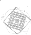
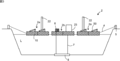
図1に示すとおり、フロート集合体2は、周囲部2aと、中央部2bから構成され、湖Lに浮かべられている。湖Lは単なる一例であり、水上であれば池または河川でもよい。湖Lの周囲の陸部には、撮影装置21および制御装置24が設置されている。以下、各構成を順に説明する。
(1.1 周囲部2a)
周囲部2aは、複数のフロート10が互いに連結されることによって構成される。フロート10は、例えば、溶融状態の筒状のパリソンを複数の分割金型で挟んで膨らますブロー成形によって製造され、成形材料には、各種の熱可塑性樹脂を使用することができるが、例えば、ポリエチレンやポリプロピレンといったポリオレフィン系樹脂を好適に用いることができる。
周囲部2aは、複数のフロート10が互いに連結されることによって構成される。フロート10は、例えば、溶融状態の筒状のパリソンを複数の分割金型で挟んで膨らますブロー成形によって製造され、成形材料には、各種の熱可塑性樹脂を使用することができるが、例えば、ポリエチレンやポリプロピレンといったポリオレフィン系樹脂を好適に用いることができる。
フロート10同士の連結に際しては、プラスチック成形体として形成される通路ジョイント60が用いられる。ここで、通路ジョイント60は、各フロート10の上面においてフロート10と結合されており、通路ジョイント60の連結方向においてフロート10が所定の間隔で結合される。
一方、通路ジョイント60による連結方向と直交する方向の連結は、各フロート10の端部を連結することで行っている。このような構成によって、本来であれば1つのフロート10にかかる荷重を隣接するフロート10へ分散することができる。
周囲部2aを構成するフロート10は、例えば数十個が連結される。これらのフロート10のうち、一部のフロート10には、ソーラパネル50が設置されている。一方、一部のフロート10には、ソーラパネル50を設置せず、ソーラパネル50の保守点検を行うための通路とされている。また、通路は、ソーラパネル50からの電気配線等(図示せず)を敷設するためにも利用されている。
周囲部2aは、一例として、全体として矩形形状をなすように構成される。このうち当該矩形の頂点部分に位置するフロート10には、回転用ワイヤ4が設けられている。この回転用ワイヤ4は、陸上に設置された回転用ウィンチ5によって巻取り可能に構成される。すなわち、回転用ウィンチ5を介して回転用ワイヤ4を巻き込んでその位置をずらすことによって、頂点部分に位置するフロート10を引っ張ることができる。
回転用ウィンチ5は、回転用ワイヤ4を巻き取るとともに回転用ワイヤ4を送り出す機構を有する。回転用ウィンチ5には、例えば、駆動装置(モーター)により駆動されるエンドレスウィンチを採用することができる。回転用ウィンチ5が回転用ワイヤ4を巻き取ると、回転用ワイヤ4には張力が発生する。
そして、これらのフロート10が引っ張られることによって、図2に示されるように、周囲部2aが中央部2bの周りを独立して回転可能に構成される。回転範囲は180度未満であればよく、湖Lの水面の大きさ、使用するフロート10の大きさ、ソーラパネル50の設置枚数に合わせて適宜設定することが好ましい。そしてこのような構成の下、ソーラパネル50が太陽の方角に向くように周囲部2aを日の出から日没までにかけて、周囲部2aがゆっくりと回転される。
周囲部2aには、周囲部2aの鉛直方向の高さを検出する際に基準となる検出ポール22が2本設けられている。検出ポール22は、一例としては円柱形であり、周囲部2aを構成するフロート10上に鉛直方向に起立して設置されている。検出ポール22を用いた周囲部2aの位置の検出については、詳細を後述する。
(1.2 中央部2b)
中央部2bは、周囲部2aと同様に、1つ又は複数のフロート10および通路ジョイント60によって構成される。周囲部2aを構成するフロート10と同一形状のフロートを用いてもよいし、異なる形状フロートを用いてもよい。
中央部2bは、周囲部2aと同様に、1つ又は複数のフロート10および通路ジョイント60によって構成される。周囲部2aを構成するフロート10と同一形状のフロートを用いてもよいし、異なる形状フロートを用いてもよい。
図3に示すように、周囲部2aが中央部2bの周りを回転可能に構成されるものに対して、中央部2bは湖Lの水底に設置された固定部8に対して、軸用ワイヤ7を介して鉛直方向の位置が制限されている。すなわち、軸用ワイヤ7の一端が固定部8(例えば、水底に埋め込まれたアンカー又は重量の大きいシンカー等)によって強固に固定され、他端が中央部2bに繋がっている。
中央部2bには、軸用ワイヤ7を巻取り可能に構成されるウィンチ機構6が設けられる。ウィンチ機構6にはマイコンが内蔵されており、外部からの指示に基づき、軸用ワイヤ7の長さを調整可能に構成されている。
すなわち、ウィンチ機構6によって、軸用ワイヤ7に適当な張力を発生させ、これを維持することができる。このように張力をかけた軸用ワイヤ7を用いることで、中央部2bの鉛直方向の位置が制限されることとなる。軸用ワイヤ7は、比較的伸び縮みの少ない金属製のものが好ましい。
周囲部2aが中央部2bの周りを回転するにあたって、中央部2b及び軸用ワイヤ7が周囲部2aの回転軸として機能する。これによって、回転に際して周囲部2aが並進移動することを抑制している。従来であれば、このような回転軸として高コストな柱を別途設ける必要があったが、本実施形態に係るフロート集合体2では、回転軸の機能を軸用ワイヤ7としてコストをかけずに実現することができる。
中央部2bには、中央部2bの鉛直方向の高さを検出する際に基準となる検出パネル23が設けられている。検出パネル23は、一例としては矩形平板状であり、中央部2bを構成するフロート10上に鉛直方向に起立して設置されている。検出パネル23を用いた周囲部2aの位置の検出については、詳細を後述する。
(1.3.管理システム1の制御)
図4を参照し、管理システム1の制御について説明する。管理システム1は、上述したフロート集合体2を構成する周囲部2aおよび中央部2bの他に、撮影装置21と制御装置24を備える。撮影装置21と制御装置24は、電気的に接続されている。
図4を参照し、管理システム1の制御について説明する。管理システム1は、上述したフロート集合体2を構成する周囲部2aおよび中央部2bの他に、撮影装置21と制御装置24を備える。撮影装置21と制御装置24は、電気的に接続されている。
撮影装置21は、周囲部2aおよび中央部2bを撮影可能に構成され、撮影した画像データを制御装置24へ送信する。周囲部2aに設けられた検出ポール22、および中央部2bに設けられた検出パネル23には、LED素子22aおよび23aがそれぞれ設けられている。そのため、撮影装置21は、夜間においても周囲部2aおよび中央部2bを撮影することができる。
制御装置24は、予め定められたタイミング(例えば、5分に1回)で、受信した画像データに対して画像解析を行い、周囲部2aと中央部2bの水位の変化に基づく鉛直方向における相対位置の変化を測定する。水位の変化に基づく位置の測定方法については、詳細を後述する。
制御装置24は、中央部2bに設けられたウィンチ機構6と有線(または無線)によって通信可能に構成されている。制御装置24は、測定した周囲部2aと中央部2bの鉛直方向における相対位置の変化に基づいて、調整すべき軸用ワイヤ7の長さを検出し、ウィンチ機構6へ送信する。ウィンチ機構6は、受信した検出結果に基づいて、軸用ワイヤ7の長さの調整を行う。
(1.4.位置の測定方法)
図5および図6を参照し、水位の変化に基づく周囲部2aと中央部2bの位置の測定方法を説明する。図5Aは、水位が基準となる位置P1である場合を示している。撮影装置21は、鉛直方向における位置が高さCとなるように固定されている。制御装置24は、撮影装置21の撮影した画像データに基づいて、高さCと検出パネル23の上面との距離A1を測定する。なお、検出パネル23の上面の位置に限定されることはなく、任意の測定位置として決めて、当該測定位置と高さCとの距離をA1としてもよい。
図5および図6を参照し、水位の変化に基づく周囲部2aと中央部2bの位置の測定方法を説明する。図5Aは、水位が基準となる位置P1である場合を示している。撮影装置21は、鉛直方向における位置が高さCとなるように固定されている。制御装置24は、撮影装置21の撮影した画像データに基づいて、高さCと検出パネル23の上面との距離A1を測定する。なお、検出パネル23の上面の位置に限定されることはなく、任意の測定位置として決めて、当該測定位置と高さCとの距離をA1としてもよい。
図5Bに示すように、水位がP1からP2へ低下した場合、水位の低下に伴い周囲部2aおよび中央部2bの鉛直方向における位置が低下し、軸用ワイヤ7が弛むこととなる。制御装置24は、撮影装置21の画像データに基づいて、高さCと検出パネル23の上面の距離A2を測定する。そして、距離A1と距離A2の差を算出し、ウィンチ機構6によって巻き取られるべき軸用ワイヤ7の長さを検出する。
さらに、図6Aに示すように、水位が基準となる位置P1である場合において、制御装置24は、撮影装置21の撮影した画像データに基づいて、検出ポール22の上面と検出パネル23の上面の距離B1を測定する。
図6Bに示すように、水位がP1からP3へ上昇した場合、水位の上昇に伴い周囲部2aの鉛直方向の位置が上昇する。それに対して、中央部2bは、軸用ワイヤ7によって鉛直方向における位置が制限されているため、鉛直方向の位置が上昇しない。制御装置24は、撮影装置21の画像データに基づいて、検出ポール22の上面と検出パネル23の上面との距離B2を測定する。そして、距離B1と距離B2との差を算出し、ウィンチ機構6によって調整されるべき軸用ワイヤ7の長さを検出する。
以上のようにして、本実施形態にかかるフロート集合体2の管理システム1は、周囲部2aと中央部2bを撮影する撮影装置21を備え、撮影装置21の撮影した画像データに基づいて、水位の変化に基づく周囲部2aと中央部2bの鉛直方向における相対位置の変化を測定する。
このような構成とすることにより、簡易な構成で精度よく、水位の変化に基づくフロート集合体2の位置の変化を検知することができる。
また、ウィンチ機構6による軸用ワイヤ7の送り出した長さに基づいて、軸用ワイヤの長さを制御するのではなく、フロート集合体2の鉛直方向の位置に基づいて制御することにより、ウィンチ機構6において発生した軸用ワイヤ7の弛みや重なりの影響を受けることなく、適切な軸用ワイヤ7の長さに調整することができる。
ここで、検出ポール22は、周囲部2aに2本設けられており、検出パネル23と検出ポール22は、平面視において三角形を形成する位置に配置されているのが好ましい。このような構成とすることにより、フロート集合体2の周囲部2aが回転することにより、撮影装置21に対して検出パネル23と一方の検出ポール22が重なったとしても、他方の検出ポールを撮影することにより正確な位置検知が可能となる。
また、検出パネル23は、検出ポール22よりも水平方向の幅が長くなるように構成されている。このような構成とすることにより、撮影装置21に対して検出パネル23と一方の検出ポール22が重なったとしても、検出パネル23の上面の位置を正確に検知することができる。
また、検出ポール22および検出パネル23に発光部22b,23bをそれぞれ設けることもできる。この場合に、2本の検出ポール22および検出パネル23の発光の態様を異ならせることができる。具体的には、図7に示すように、一方の検出ポールの発光部22b1と、他方の検出ポールの発光部22b1の表面の模様を異なるものとすることができる。そして、一例として、発光部22b1は上部から黄色、赤色、黄色に発光させ、発光部22b2は上部から黄色、赤色、黄色、赤色に発光させればよい。このように、発光部22b,23bに模様を設けることにより、模様の境目を高さ検出の基準とすることもできる。
また、制御装置24は、撮影装置21が撮影した画像データにおける検出ポール22の位置に基づいて、周囲部2aの回転角度を算出してもよい。このようにすることで、ウィンチ機構6による制御だけでは検知できない波風の影響による誤差の発生を検知し、より正確に周囲部2aの回転を制御することが可能となる。
<2.第2実施形態>
図8は、第2実施形態に係るフロート集合体2の平面図である。第1実施形態に係るフロート集合体2と同様、周囲部2aと、中央部2bとから構成され、湖Lの水面に浮かべられている。ここで、第2実施形態に係るフロート集合体2では、周囲部2aと中央部2bとの境界において、円滑機構9が設けられている点が第1実施形態と異なる。以下、相違点を中心に説明する。
図8は、第2実施形態に係るフロート集合体2の平面図である。第1実施形態に係るフロート集合体2と同様、周囲部2aと、中央部2bとから構成され、湖Lの水面に浮かべられている。ここで、第2実施形態に係るフロート集合体2では、周囲部2aと中央部2bとの境界において、円滑機構9が設けられている点が第1実施形態と異なる。以下、相違点を中心に説明する。
図8に示すように、フロート集合体2は、数百のフロート10を有する周囲部2aと、複個のフロート10を有する中央部2bと、円滑機構9とを備える。第2実施形態においては、周囲部2aの上面視形状は略円形となっており、周囲部2aは中央部2bを中心として回転しやすくなっている。また、周囲部2aは、ソーラパネル50が配置されるフロート10と、各ソーラパネル50から延びる配線がまとめられている配線用フロート70とを有する。
配線用フロート70には接続箱(図示せず)が設置されており、各ソーラパネル50から延びる配線は、この接続箱に電気的に接続されている。つまり、配線用フロート70の接続箱は、各ソーラパネル50から延びる配線をまとめる機能を有する。また、配線用フロート70の接続箱には、伝送線(図示せず)が接続されている。伝送線71は、ソーラパネル50と、パワーコンディショナー(図示せず)とを電気的に接続する機能を有し、ソーラパネル50で発電された電力は伝送線を介してパワーコンディショナーへ伝達される。パワーコンディショナーは水上に設けられていてもよく、陸上に設けられていてもよい。なお、伝送線を周囲部2aのフロート10同士の隙間に通すことで、伝送線を水中に引き込んでもよい。
第2実施形態に係るフロート集合体2は、回転用ウィンチ5を1つ備える。回転用ウィンチ5は、周囲部2aの周囲に張り巡らされた回転用ワイヤ4の巻取り、および送り出しを行うことにより、周囲部2aを中央部2bに対して回転させる。
第2実施形態のようなフロート集合体においても、たとえば、周囲部2aの最も内側のフロート10上に2つの検出ポール22を設け、中央部の1つのフロート10上に検出パネルを設けることにより、第1実施形態と同様の効果を奏することができる。ここで、撮影装置21、制御装置24、および回転用ウィンチ5を、管理装置80として1つの装置としてまとめることにより、これらの装置を設置するための地盤確保の回数を減らすことができる。
さらに、第2実施形態においては、管理装置80は撮影装置21をもうひとつ備えていて、太陽の位置を検出可能としている。すなわち、日光の照射方向から水平面および垂直面に対する角度を検出し、検出結果に基づいて、回転用ウィンチ5が周囲部2aの回転を制御する構成としてもよい。この場合、検出ポール22および検出パネル23を利用することにより、フロート集合体の位置および回転角度を正確に把握することが可能となる。なお、曇天の場合には、前日の制御結果に基づいて周囲部2aの回転を制御してもよいし、周囲部2aの回転制御を行わない仕様としてもよい。また、太陽位置を検出するための撮影装置21を管理装置80が備えることにより、メンテナンスを容易に行うことができる。
<3.他の実施形態>
本発明に係る種々の実施形態を説明したが、これらは、例として提示したものであり、発明の範囲を限定することは意図していない。
本発明に係る種々の実施形態を説明したが、これらは、例として提示したものであり、発明の範囲を限定することは意図していない。
上記実施形態においては、水位が低下した場合は基準となる位置Cと検出パネル23の上面の位置との距離に基づいて位置の変化を測定し、水位が上昇した場合は検出ポール22と検出パネル23の上面の位置との距離に基づいて位置の変化を測定していたが、この例に限定されることはない。例えば、水位が低下した場合には、位置Cと検出ポール22の上面の位置との距離に基づいて位置の変化を測定してもよい。また、水位が上昇した場合は、位置Cと検出ポール22の上面の位置との距離に基づいて位置の変化を測定してもよい。
また、上記実施形態においては、管理システム1は、周囲部2aと中央部2bの鉛直方向の相対位置を測定して軸用ワイヤ7の長さを調整しているが、周囲部2aと中央部2bの鉛直方向の位置をそれぞれ測定して、軸用ワイヤ7の長さを調整しても良い。
また、上記第2実施形態においては、管理装置80として、2つの撮影装置21、制御装置24、および回転用ウィンチ5が1つの装置にまとめられているが、この形態に限定されることはなく、それぞれの装置が互いに近い位置に配置されている態様でもよい。
上述した実施形態は、その他の様々な形態で実施されることが可能であり、発明の要旨を逸脱しない範囲で、種々の省略、置き換え、変更を行うことができる。当該実施形態やその変形は、発明の範囲や要旨に含まれるとともに、特許請求の範囲に記載された発明とその均等の範囲に含まれるものである。
1:管理システム、2:フロート集合体、2a:周囲部、2b:中央部、4:回転用ワイヤ、5:回転用ウィンチ、6:ウィンチ機構、7:軸用ワイヤ、8:固定部、9:円滑機構、10:フロート、21:撮影装置、22:検出ポール、23:検出パネル、24:制御装置、50:ソーラパネル、60:通路ジョイント、70:配線フロート、80:管理装置
Claims (8)
- 水上に配置されるフロート集合体の配置を管理するシステムであって、
前記フロート集合体は、
鉛直方向における位置が制限された中央部と、
前記中央部の周囲における水面に浮上するように配置された周囲部を備え、
前記システムは、
前記中央部と前記周囲部を撮影する撮影装置を備え、
前記撮影装置の撮影した画像データに基づいて、水位の変化に基づく前記中央部と前記周囲部の鉛直方向における位置の変化を測定する、システム。 - 前記撮影装置は、鉛直方向における位置が固定されている、請求項1に記載のシステム。
- 前記中央部は、水中に向かうように設けられたワイヤによって鉛直方向における位置が制限され、
前記システムは、測定された前記位置の変化に基づいて、前記ワイヤの長さを制御する、請求項1または請求項2に記載のシステム。 - 前記中央部には、鉛直方向の位置を検出する際に基準となる検出パネルが設けられている、請求項1~請求項3のいずれか1項に記載のシステム。
- 前記周囲部には、鉛直方向の位置を検出する際に基準となる検出ポールが設けられている、請求項4に記載のシステム。
- 前記検出ポールは、前記周囲部に2本設けられており、
前記検出パネルと前記検出ポールは、平面視において三角形を形成する位置に配置されている、請求項5に記載のシステム。 - 前記検出パネルは、前記検出ポールよりも水平方向の幅が長くなるように構成されている、請求項5または請求項6に記載のシステム。
- 前記検出パネルと前記検出ポールは発光部を備える、請求項5~請求項7のいずれか1項に記載のシステム。
Applications Claiming Priority (2)
| Application Number | Priority Date | Filing Date | Title |
|---|---|---|---|
| JP2019-135705 | 2019-07-23 | ||
| JP2019135705A JP2021018214A (ja) | 2019-07-23 | 2019-07-23 | フロート集合体を管理するシステム |
Publications (1)
| Publication Number | Publication Date |
|---|---|
| WO2021015262A1 true WO2021015262A1 (ja) | 2021-01-28 |
Family
ID=74192996
Family Applications (1)
| Application Number | Title | Priority Date | Filing Date |
|---|---|---|---|
| PCT/JP2020/028521 Ceased WO2021015262A1 (ja) | 2019-07-23 | 2020-07-22 | フロート集合体を管理するシステム |
Country Status (3)
| Country | Link |
|---|---|
| JP (1) | JP2021018214A (ja) |
| TW (1) | TW202112609A (ja) |
| WO (1) | WO2021015262A1 (ja) |
Families Citing this family (1)
| Publication number | Priority date | Publication date | Assignee | Title |
|---|---|---|---|---|
| JP2023102257A (ja) * | 2022-01-11 | 2023-07-24 | 三井住友建設株式会社 | 太陽光フロートユニット |
Citations (3)
| Publication number | Priority date | Publication date | Assignee | Title |
|---|---|---|---|---|
| WO2004076972A1 (ja) * | 2003-02-27 | 2004-09-10 | Mitsubishi Denki Kabushiki Kaisha | 水位計測システム |
| US20140245941A1 (en) * | 2011-07-13 | 2014-09-04 | Technische Universität Wien | Arrangement of floating platforms |
| JP2018502777A (ja) * | 2014-12-30 | 2018-02-01 | ビーケー エナジー シーオー., エルティーディー. | 浮遊式水上太陽光発電装置 |
-
2019
- 2019-07-23 JP JP2019135705A patent/JP2021018214A/ja active Pending
-
2020
- 2020-07-22 WO PCT/JP2020/028521 patent/WO2021015262A1/ja not_active Ceased
- 2020-07-23 TW TW109124884A patent/TW202112609A/zh unknown
Patent Citations (3)
| Publication number | Priority date | Publication date | Assignee | Title |
|---|---|---|---|---|
| WO2004076972A1 (ja) * | 2003-02-27 | 2004-09-10 | Mitsubishi Denki Kabushiki Kaisha | 水位計測システム |
| US20140245941A1 (en) * | 2011-07-13 | 2014-09-04 | Technische Universität Wien | Arrangement of floating platforms |
| JP2018502777A (ja) * | 2014-12-30 | 2018-02-01 | ビーケー エナジー シーオー., エルティーディー. | 浮遊式水上太陽光発電装置 |
Also Published As
| Publication number | Publication date |
|---|---|
| TW202112609A (zh) | 2021-04-01 |
| JP2021018214A (ja) | 2021-02-15 |
Similar Documents
| Publication | Publication Date | Title |
|---|---|---|
| US9074339B2 (en) | Method for installing an underwater support column | |
| US11407480B2 (en) | Float assembly | |
| KR101982802B1 (ko) | 부유식 수상 태양광 발전시스템의 계류 및 회전장치 | |
| US11772755B2 (en) | Floatable offshore wind turbine | |
| CN103459247B (zh) | 用于控制水上结构物的装置及方法 | |
| WO2016108561A1 (ko) | 부유식 수상 태양광 발전 장치 | |
| KR200452268Y1 (ko) | 각도조절이 가능한 추 지지형 수상 태양광 발전장치 | |
| KR101232314B1 (ko) | 수면 부상형 태양광 발전장치 | |
| KR101194783B1 (ko) | 수상 구조물 | |
| WO2021015262A1 (ja) | フロート集合体を管理するシステム | |
| JP2007118925A (ja) | 水上発電装置 | |
| KR101268176B1 (ko) | 수상 구조물 | |
| KR101159780B1 (ko) | 파력발전시스템 | |
| KR101433513B1 (ko) | 부유식 태양광 발전 추적 시스템 | |
| WO2019027282A1 (ko) | 부유식 수상 태양광 발전시스템의 계류 및 회전장치 | |
| CN116353769B (zh) | 一种智能式航道指示灯标 | |
| WO2020149732A1 (en) | Modular floating solar apparatus | |
| CN210689627U (zh) | 一种水文及气象观测装置 | |
| KR101970405B1 (ko) | 수상 태양광 부유구조물의 발전효율을 높이기 위한 일광추적 계류장치 및 이를 이용한 계류방법 | |
| ITVR20080097A1 (it) | Dispositivo modulare per il supporto di pannelli solari e relativo impianto | |
| CN221646530U (zh) | 新型光伏停车棚 | |
| CN206060627U (zh) | 一种渔光互补的光伏电站支架及具有该支架的支架组件 | |
| JP7492283B1 (ja) | 着床式洋上架台の構築方法、着床式洋上架台、及び洋上風力発電装置 | |
| CN218895161U (zh) | 一种可升降的草原气候监测仪 | |
| CN219511630U (zh) | 一种水土保持用监测装置 |
Legal Events
| Date | Code | Title | Description |
|---|---|---|---|
| 121 | Ep: the epo has been informed by wipo that ep was designated in this application |
Ref document number: 20845081 Country of ref document: EP Kind code of ref document: A1 |
|
| NENP | Non-entry into the national phase |
Ref country code: DE |
|
| 122 | Ep: pct application non-entry in european phase |
Ref document number: 20845081 Country of ref document: EP Kind code of ref document: A1 |