WO2021014547A1 - Terminal and communication method - Google Patents
Terminal and communication method Download PDFInfo
- Publication number
- WO2021014547A1 WO2021014547A1 PCT/JP2019/028716 JP2019028716W WO2021014547A1 WO 2021014547 A1 WO2021014547 A1 WO 2021014547A1 JP 2019028716 W JP2019028716 W JP 2019028716W WO 2021014547 A1 WO2021014547 A1 WO 2021014547A1
- Authority
- WO
- WIPO (PCT)
- Prior art keywords
- terminal
- transmission power
- value
- side link
- reference signal
- Prior art date
Links
Images


Classifications
-
- H—ELECTRICITY
- H04—ELECTRIC COMMUNICATION TECHNIQUE
- H04W—WIRELESS COMMUNICATION NETWORKS
- H04W52/00—Power management, e.g. TPC [Transmission Power Control], power saving or power classes
- H04W52/04—TPC
- H04W52/38—TPC being performed in particular situations
- H04W52/383—TPC being performed in particular situations power control in peer-to-peer links
-
- H—ELECTRICITY
- H04—ELECTRIC COMMUNICATION TECHNIQUE
- H04W—WIRELESS COMMUNICATION NETWORKS
- H04W52/00—Power management, e.g. TPC [Transmission Power Control], power saving or power classes
- H04W52/04—TPC
- H04W52/30—TPC using constraints in the total amount of available transmission power
- H04W52/32—TPC of broadcast or control channels
- H04W52/325—Power control of control or pilot channels
-
- H—ELECTRICITY
- H04—ELECTRIC COMMUNICATION TECHNIQUE
- H04W—WIRELESS COMMUNICATION NETWORKS
- H04W4/00—Services specially adapted for wireless communication networks; Facilities therefor
- H04W4/30—Services specially adapted for particular environments, situations or purposes
- H04W4/40—Services specially adapted for particular environments, situations or purposes for vehicles, e.g. vehicle-to-pedestrians [V2P]
-
- H—ELECTRICITY
- H04—ELECTRIC COMMUNICATION TECHNIQUE
- H04W—WIRELESS COMMUNICATION NETWORKS
- H04W52/00—Power management, e.g. TPC [Transmission Power Control], power saving or power classes
- H04W52/04—TPC
- H04W52/06—TPC algorithms
- H04W52/08—Closed loop power control
-
- H—ELECTRICITY
- H04—ELECTRIC COMMUNICATION TECHNIQUE
- H04W—WIRELESS COMMUNICATION NETWORKS
- H04W52/00—Power management, e.g. TPC [Transmission Power Control], power saving or power classes
- H04W52/04—TPC
- H04W52/06—TPC algorithms
- H04W52/10—Open loop power control
-
- H—ELECTRICITY
- H04—ELECTRIC COMMUNICATION TECHNIQUE
- H04W—WIRELESS COMMUNICATION NETWORKS
- H04W52/00—Power management, e.g. TPC [Transmission Power Control], power saving or power classes
- H04W52/04—TPC
- H04W52/18—TPC being performed according to specific parameters
- H04W52/24—TPC being performed according to specific parameters using SIR [Signal to Interference Ratio] or other wireless path parameters
- H04W52/242—TPC being performed according to specific parameters using SIR [Signal to Interference Ratio] or other wireless path parameters taking into account path loss
-
- H—ELECTRICITY
- H04—ELECTRIC COMMUNICATION TECHNIQUE
- H04W—WIRELESS COMMUNICATION NETWORKS
- H04W72/00—Local resource management
- H04W72/12—Wireless traffic scheduling
- H04W72/1263—Mapping of traffic onto schedule, e.g. scheduled allocation or multiplexing of flows
-
- H—ELECTRICITY
- H04—ELECTRIC COMMUNICATION TECHNIQUE
- H04W—WIRELESS COMMUNICATION NETWORKS
- H04W72/00—Local resource management
- H04W72/20—Control channels or signalling for resource management
-
- H—ELECTRICITY
- H04—ELECTRIC COMMUNICATION TECHNIQUE
- H04W—WIRELESS COMMUNICATION NETWORKS
- H04W92/00—Interfaces specially adapted for wireless communication networks
- H04W92/16—Interfaces between hierarchically similar devices
- H04W92/18—Interfaces between hierarchically similar devices between terminal devices
Definitions
- the present invention relates to terminals and communication methods in wireless communication systems.
- LTE Long Term Evolution
- LTE-A Long Term Evolution Advanced
- NR New Radio
- 5G New Radio
- UE User Equipment
- Side link also called D2D (Device to Device)
- V2X Vehicle to Everything
- V2X is a part of ITS (Intelligent Transport Systems), and as shown in FIG. 1, V2V (Vehicle to Vehicle), which means a communication mode between automobiles, is installed on the side of an automobile and a road.
- V2I Vehicle to Infrastructure
- RSU road-side unit
- V2N Vehicle to
- Nomadic device and V2P (Vehicle to Pedestrian), which means a communication mode between a car and a pedestrian mobile terminal.
- 3GPP TS 36.213 V15.2.0 (2018-06) 3GPP TS 38.211 V15.6.0 (2019-06) 3GPP TS 38.214 V15.5.0 (2019-03) 3GPP TS 38.331 V15.5.1 (2019-04)
- SL side link
- NR New Radio
- OLPC open-loop transmitter power control
- CSI-RS Channel State Information Reference Signal
- PTRS Phase Tracking Reference Signal
- the reference signal is frequency-division-multiplexed when the data transmitted on the shared channel of the side link and the reference signal of the side link are frequency-divided and multiplexed.
- a control unit that sets the first value of the transmission power for transmitting the data to the same value or a different value as the second value of the transmission power for transmitting the data, and the first value of the transmission power.
- a terminal comprising the reference signal and a transmission unit for transmitting the data by applying the second value of the transmission power to the data and applying the reference signal.
- V2X V2X
- side link It is a figure for demonstrating the side link. It is a figure for demonstrating the side link. It is a figure for demonstrating the MAC PDU used for the side link communication. It is a figure for demonstrating the format of SL-SCH subhader. It is a figure for demonstrating the example of the channel structure used in the side link in LTE-V2X. It is a figure which shows the configuration example of the wireless communication system which concerns on embodiment. It is a figure for demonstrating the resource selection operation of a terminal. It is a figure which shows the outline of SL transmission mode 1 defined by V2X of NR. It is a figure which shows the outline of SL transmission mode 2a.
- the method of direct communication between terminals in the present embodiment is assumed to be LTE or NR side link (SL (Sidelink)), but the method of direct communication is not limited to this method.
- SL Sidelink
- the name "side link” is an example, and the name “side link” may not be used, and UL (Uplink) may include the function of SL.
- SL may be distinguished from DL (Downlink) or UL by the difference in frequency or time resource, or may have another name.
- UL and SL refer to a time resource, a frequency resource, a time / frequency resource, a reference signal for determining Pathloss in transmission power control, and a reference signal (PSS / SSS / PSSS / SSSS) used for synchronization. ) May be distinguished by the difference in any one or a plurality of combinations.
- the reference signal of antenna port X_ANT is used as a reference signal to be referred to in determining Pathloss in transmission power control, and in SL (including UL used as SL), Pathloss is determined in transmission power control.
- the reference signal to be referred to the reference signal of the antenna port Y_ANT is used.
- a terminal which may be called a user device (UE)
- UE user device
- the embodiment of the present invention is not limited to this mode.
- the terminal may be a terminal held by a person
- the terminal may be a device mounted on a drone or an aircraft
- the terminal may be a base station, an RSU, a relay station (relay node), and a scheduling ability. It may be a user device or the like.
- side link is used as the basic technology
- the outline of the side link will be described as a basic example.
- An example of the technique described here is 3GPP Rel. This is the technology specified in 14 mag.
- the technique may be used in the NR, or a technique different from the technique may be used in the NR.
- side-link communication may be defined as direct communication performed between two or more adjacent user devices while using E-UTRA technology without going through a network node.
- Sidelinks may be defined as interfaces between user devices in sidelink communication.
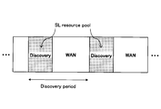
- a resource pool for Discovery messages is set (configured) for each Discovery period, and a terminal (referred to as UE) is a Discovery message (discovery signal) in the resource pool.
- UE a terminal
- Discovery message discovery signal
- the terminal may autonomously select a transmission resource from the resource pool.
- quasi-static resources may be allocated by higher layer signaling (eg, RRC signal) (instead of higher layer signaling, PC5-RRC, which is a sidelink RRC signaling, may be applied, DCI and / Or SCI may be applied).
- a resource pool for SCI (Sidelink Control Information) / data transmission is periodically set for each SC (Sidelink Control) period.
- the terminal on the transmitting side notifies the receiving side of the data transmission resource (PSSCH resource pool) or the like by SCI with the resource selected from the Control resource pool (PSCCH resource pool), and transmits the data with the data transmission resource.
- modes 1 and 2 for "communication resources may be dynamically allocated by (E) PDCCH ((Enhanced) Physical Downlink Control Channel) sent from the base station to the terminal.
- PDCCH Physical Downlink Control Channel
- the terminal may autonomously select a transmission resource from the resource pool.
- the resource pool a predefined one is used, such as being notified by SIB (MIB, upper layer signaling, PC5-RRC which is RRC signaling of side link, etc. may be applied instead of SIB). You may.
- Rel-14 in addition to mode 1 and mode 2, there are mode 3 and mode 4.
- SCI and data can be transmitted simultaneously (in one subframe) in resource blocks adjacent in the frequency direction.
- SCI may be referred to as SA (scheduling association).
- PSDCH Physical Sidelink Discovery Channel
- PSCCH Physical Sidelink Control Channel
- PSCCH Physical Sidelink Control Channel
- PSCCH Physical Sidelink Control Channel
- PSCH Physical Sidelink Shared Channel
- PSCCH and the PSSCH have a PUSCH-based structure, and may have a structure in which a DMRS (Demodulation Reference Signal, demodulation reference signal) is inserted.
- PSCCH may be referred to as a side link control channel
- PSCCH may be referred to as a side link shared channel.
- the signal transmitted via the PSCCH may be referred to as a sidelink control signal
- the signal transmitted via the PSCCH may be referred to as a sidelink data signal.
- the MAC (Medium Access Control) PDU (Protocol Data Unit) used for the side link may be composed of at least a MAC header, a MAC Control element, a MAC SDU (Service Data Unit), and Padding.
- the MAC PDU may contain other information.
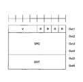
- the MAC header may be composed of one SL-SCH (Sidelink Sharped Channel) subheader and one or more MAC PDU subheaders.
- the SL-SCH subheader may be composed of a MAC PDU format version (V), source information (SRC), destination information (DST), Reserved bit (R), and the like.
- V is assigned to the beginning of the SL-SCH subheader and may indicate the MAC PDU format version used by the terminal.
- Information about the sender may be set in the sender information.
- An identifier related to the ProSe UE ID may be set in the source information.
- Information about the destination may be set in the destination information. In the destination information, information related to the ProSe Layer-2 Group ID of the destination may be set.
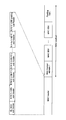
- FIG. 5 shows an example of the side link channel structure in LTE-V2X.
- a PSCCH resource pool and a PSCH resource pool used for "communication” may be allocated.
- the PSDCH resource pool used for "discovery” is allocated in a cycle longer than the cycle of the "communication" channel. Note that PSDCH may not be included in NR-V2X.
- PSSS Primary Sidelink Synchronization signal
- SSSS Secondary Sidelink Synchronization signal
- PSBCH Physical Sidelink Broadcast Channel
- PSSS / SSSS and PSBCH are transmitted, for example, in one subframe.
- PSSS / SSSS may be referred to as SLSS.
- V2X assumed in this embodiment is a method related to "communication”. However, in the present embodiment, it may be assumed that there is no distinction between “communication” and “discovery”. In addition, the technique according to this embodiment may be applied in "discovery”.
- FIG. 6 is a diagram showing a configuration example of the wireless communication system according to the present embodiment.
- the wireless communication system according to the present embodiment includes a base station 10, a terminal 20A, and a terminal 20B. Although there may actually be a large number of terminals, FIG. 6 shows terminals 20A and 20B as examples.
- the terminal 20A is intended to be the transmitting side and the terminal 20B is intended to be the receiving side, but both the terminal 20A and the terminal 20B have both a transmitting function and a receiving function.
- terminal 20 when the terminals 20A, 20B and the like are not particularly distinguished, they are simply described as "terminal 20" or "terminal".
- FIG. 6 shows a case where both the terminal 20A and the terminal 20B are within the coverage as an example, but the operation in the present embodiment is a case where all the terminals 20 are within the coverage and a case where some terminals 20 are within the coverage. It can be applied to both the case where the terminal 20 is in the coverage and the other terminal 20 is out of the coverage, and the case where all the terminals 20 are out of the coverage.
- the terminal 20 is a device mounted on a vehicle such as an automobile, and has a cellular communication function as a user device (UE) in LTE or NR and a side link function. .. Further, the terminal 20 includes a function of acquiring report information (position, event information, etc.) such as a GPS device, a camera, and various sensors. Further, the terminal 20 may be a general mobile terminal (smartphone or the like). Further, the terminal 20 may be an RSU. The RSU may be a UE type RSU having a UE function, a BS type RSU having a base station function (may be called a gNB type UE), or a relay station.
- UE user device
- NR side link function
- the terminal 20 includes a function of acquiring report information (position, event information, etc.) such as a GPS device, a camera, and various sensors.
- the terminal 20 may be a general mobile terminal (smartphone or the like).
- the terminal 20 may be an RSU.
- the terminal 20 does not have to be a device in one housing.
- the device including the various sensors is the terminal 20.
- the terminal 20 may be provided with a function of transmitting and receiving data to and from various sensors without including various sensors.
- the processing content of the side link transmission of the terminal 20 is basically the same as the processing content of UL transmission in LTE or NR.
- the terminal 20 scrambles and modulates the code word of the transmission data to generate complex-valued symbols, maps the complex-valued symbols (transmission signal) to one or two layers, and performs precoding. Then, the precoded complex-valued symbols are mapped to the resource element to generate a transmission signal (eg, CP-OFDM, DFT-s-OFDM), which is transmitted from each antenna port.
- a transmission signal eg, CP-OFDM, DFT-s-OFDM
- the base station 10 a function of cellular communication as the base station 10 in LTE or NR and a function for enabling communication of the terminal 20 in the present embodiment (eg, resource pool setting, resource allocation, etc.) )have.
- the base station 10 may be an RSU (gNB type RSU), a relay station, or a terminal having a scheduling function.
- RSU gNB type RSU
- the signal waveform used by the terminal 20 for SL or UL may be OFDMA, SC-FDMA, or other signal waveform. You may.
- a frame composed of a plurality of subframes (example: 10 subframes) is formed in the time direction, and the frequency direction is from a plurality of subcarriers.
- TTI Transmission Time Interval
- TTI is not always a subframe.
- TTI may be a slot or mini-slot or other time domain unit.
- the number of slots per subframe may be determined according to the subcarrier interval.
- the number of symbols per slot may be 14 symbols.
- one symbol may include a Cyclic Prefix (CP), which is a guard period for reducing intersymbol interference caused by multipath.
- CP Cyclic Prefix
- the terminal 20 is in mode 1, in which resources are dynamically allocated by the (E) PDCCH ((Enhanced) Physical Downlink Control Channel) sent from the base station 10 to the terminal, and the terminal autonomously resources.
- Mode 2 which is a mode for selecting transmission resources from the pool, mode in which resources for SL signal transmission are allocated from the base station 10 (hereinafter referred to as mode 3), and resources for SL signal transmission are autonomously selected.
- Any mode of the mode (hereinafter referred to as mode 4) can be taken.
- the mode is set, for example, by performing higher layer signaling (eg, notification of parameters such as scheduled or ue-Selected) from the base station 10 to the terminal 20.
- the mode 4 terminal selects wireless resources from a synchronized common time / frequency grid (or time and frequency domain). For example, the terminal 20 performs sensing in the background, identifies a resource having a good sensing result and is not reserved for another terminal as a candidate resource, and selects a resource to be used for transmission from the candidate resources. To do.
- V2X of NR the same transmission mode as SL transmission mode 3 and SL transmission mode 4 defined in LTE V2X is defined.
- the transmission mode may be read as a resource allocation mode, and the name is not limited to this.
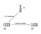
- FIG. 8A is a diagram showing an outline of SL transmission mode 1 defined by V2X of NR.
- the SL transmission mode 1 specified by V2X of NR corresponds to the SL transmission mode 3 specified by V2X of LTE.
- the base station 10 schedules transmission resources and allocates transmission resources to the transmission side terminal 20A.
- the terminal 20A transmits a signal to the receiving terminal 20B by the allocated transmission resource.
- FIGS. 8B, 8C, and 8D are diagrams showing an outline of SL transmission mode 2 defined by V2X of NR.
- the SL transmission mode 2 specified by V2X of NR corresponds to the SL transmission mode 4 specified by V2X of LTE.
- FIG. 8B is a diagram showing an outline of SL transmission mode 2a.
- the transmitting terminal 20A autonomously selects a transmission resource and transmits a signal to the receiving terminal 20B by the selected transmission resource.
- FIG. 8C is a diagram showing an outline of SL transmission mode 2c.
- the base station 10 presets the transmission resource of a fixed cycle / pattern for the terminal 20A (for example, by the parameter of the upper layer), and the terminal 20A is preset.
- a signal is transmitted to the receiving terminal 20B by a transmission resource having a constant cycle / pattern.
- the transmission resource of the constant cycle / pattern is set in advance for the terminal 20A. It may have been done.
- FIG. 8D is a diagram showing an outline of SL transmission mode 2d.
- the terminal 20 performs the same operation as the base station 10. Specifically, the terminal 20 schedules the transmission resource and allocates the transmission resource to the transmission side terminal 20A. The terminal 20A may transmit to the receiving terminal 20B by the allocated communication resource. That is, the terminal 20 may control the transmission of another terminal 20 (for example, the terminal 20A and / or the terminal 20B).
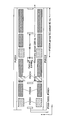
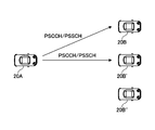
- NR As shown in FIGS. 9A to 9C, three types of communication, unicast, group cast, and broadcast, are currently under consideration.
- FIG. 9A is a diagram showing an example of unicast Physical Sidelink Sharp Channel (PSCCH) / Physical Sidelink Control Channel (PSSCH) transmission.
- Unicast means, for example, one-to-one transmission from the transmitting side terminal 20A to the receiving side terminal 20B.
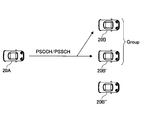
- FIG. 9B is a diagram showing an example of group cast PSCCH / PSCH transmission.
- the group cast means, for example, transmission from the transmitting side terminal 20A to the terminal 20B and the terminal 20B'which are a group of the receiving side terminal 20.
- FIG. 9C is a diagram showing an example of broadcast PSCCH / PSCH transmission.
- Broadcast refers to, for example, transmission from terminal 20A on the transmitting side to all terminals 20 on the receiving side within a predetermined range, terminal 20B, terminal 20B', and terminal 20B''.
- Release 16 of 3GPP is expected to support open-loop transmission power control (open-loop transmitter power control, OLPC).
- open-loop transmission power control the terminal 20 measures the received power of the signal from the base station and determines the uplink transmission power.
- downlink (DL) propagation loss path loss
- Unicast and group cast have been introduced in NR side-link communication, and it is relatively easy to measure the side-link path loss. Therefore, in the open-loop transmission power control of NR side-link communication, downlink It is envisioned to use link path loss and / or side link path loss.
- the receiving terminal 20 transmits the side-link RSRP (SL-Reference Signal Received Power) to the transmitting terminal 20.
- the terminal 20 on the transmitting side estimates the path loss (may be measured, calculated, derived, etc.). It is expected that how to estimate the path loss of open-loop transmission power control before SL-RSRP becomes available at the receiving terminal 20 will be examined in the future.
- the base station 10 measures the uplink received power and specifies the transmission power of the terminal 20.
- the side link of Release 16 adopts the closed loop transmission power control, that is, the TPC (Transmission Power Control) command is supported in the transmission power control of the side link.
- TPC Transmission Power Control
- future NR sidelinks may employ closed-loop transmit power control, and the present disclosure may be applied where closed-loop transmit power control is used.
- the terminal 20 setting the terminal 20 to use only the path loss of the downlink (DL: between the terminal 20 on the transmitting side and the base station 10 (gNB)), the side link Set the terminal 20 to use only the path loss (SL: between the transmitting side terminal 20 and the receiving side terminal 20), and set the terminal 20 to use the downlink path loss and the side link path loss. It is supposed to be possible to set.
- the terminal 20 is set to use the downlink path loss and the side link path loss in the NR side link open-loop transmission power control, it is derived by the open-loop transmission power control based on the downlink path loss.
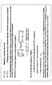
- FIG. 10 is a diagram showing an example of a mathematical formula used for transmission power control in the LTE side link. According to the mathematical formula shown in FIG. 10, the transmission power is distributed between the Physical Sidelink Shared Channel (PSSCH) and the Physical Sidelink Control Channel (PSCCH). According to the mathematical formula shown in FIG. 10, the transmission power allocated to the PSCCH is larger than the transmission power allocated to the PSCCH.
- PSSCH Physical Sidelink Shared Channel
- PSCCH Physical Sidelink Control Channel
- CSI-RS Channel State Information Reference Signal
- PTRS Phase Tracking Reference Signal
- CSI-RS may mean side-link CSI-RS
- PT-RS may mean sidelink PT-RS (SL-PT-RS).
- SL-CSI-RS may be RS used for CSI measurement of side links and the like.
- SL-PT-RS may be RS used for side link phase compensation.
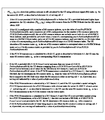
- 11A, 11B, and 11C show the transmission power of the reference signal assigned to the PDSCH or PUSCH in NR-Uu (the interface between the 5G terminal 20 and the 5G Radio Access Network (RAN)).
- RAN Radio Access Network
- FIG. 11A is a diagram showing an example of the provision of boost for PTRS of the uplink of NR-Uu.
- the phase-tracking reference signal (PT-RS) is transmitted only in the resource block used for the PUSCH.
- PT-RS is a formula
- W is a precoding matrix
- ⁇ PTRS is an amplifier scaling factor.
- the amplitude scaling factor ⁇ PTRS is applied to the PTRS and the transmission power of the PTRS is boosted as compared to the transmission power assigned to the PUSCH.
- k'and ⁇ may be notified by the parameters of the upper layer.
- FIG. 11B is a diagram showing an example of a provision for boosting the downlink of NR-Uu to PTRS.
- Table 4.1.2 shown in the example of FIG. 11B, the ratio ( ⁇ PTRS ) of PT-RS Energy per Resource Amplitude (EPRE) to EPRE of Physical Downlink Sharp Channel (PDSCH) for each resource element and for each layer. ) Is defined as the amplitude scaling factor ⁇ PTRS .
- the parameter epre-Ratio of the upper layer is set to zero and the number of PDSCH layers is larger than 1, the value of ⁇ PTRS becomes larger than 1, and the value of PTRS becomes larger than 1.
- the transmission power will be boosted (increased) with respect to the transmission power allocated to the PDSCH.
- FIG. 11C is a diagram showing an example of a regulation for boosting NR-Uu to CSI-RS.
- the EPRE of the downlink CSI-RS is the downlink transmission power of the Synchronization Signal and Physical Broadcast Channel (SS / PBCH) block given by the parameter ss-PBCH-BlockPower and the downlink transmission power given by the parameter powerControlOff. It is stipulated that it is derived by the power offset of. That is, the transmission power of the CSI-RS may be boosted with respect to the transmission power of the SS / PBCH block.
- SS / PBCH Synchronization Signal and Physical Broadcast Channel
- the terminal 20 may be able to set the value of the transmission power of the CSI-RS associated with the PSCH to a value different from the value of the transmission power assigned to the PSCH. Further, the terminal 20 may be able to set the value of the transmission power of the PT-RS associated with the PSCH to a value different from the value of the transmission power assigned to the PSCH.
- the function for determining (calculating, deriving, etc.) the transmission power of the CSI-RS may be a function in which the value of the transmission power assigned to the PSSCH is used as a variable.
- the function for calculating the transmission power of the PT-RS may be a function in which the value of the transmission power assigned to the PSSCH is used as a variable.
- the transmission power of CSI-RS may be able to be calculated using the ratio to the value of the transmission power assigned to the PSCH.
- the transmission power of the PT-RS may be able to be calculated using the ratio to the value of the transmission power assigned to the PSCH.
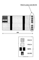
- FIG. 12 is a diagram showing an example of a slot configuration including a PSCCH symbol with CSI-RS.
- the transmission power P CSIRS of CSI-RS and the transmission power P PSSCH, b of the PSSCH symbol accompanied by CSI-RS may be defined as follows.
- ⁇ may be a value defined in the specification (for example, a fixed value or a variable), a parameter set (in advance), or a specified parameter.
- P PSSCH, a may be the transmission power of the PSCCH symbol without PSCCH and CSI-RS, or may be the transmission power of each symbol of PSCCH and / or PSCH.
- N CSIRS may be a value based on the amount of CSI-RS resources, and may be, for example, the number of CSI-RS resource elements (REs) included in the symbols in the Physical Resource Block (PRB). ..
- N PSSCH may be a value based on the amount of resources of PSSCH, and may be, for example, the number of REs of PSSCH included in the symbols in PRB.
- the total transmission power assigned to each symbol in the one-slot section shown in FIG. 12 may be maintained at a constant value.
- the terminal 20 boosts the transmission power allocated to the CSI-RS and allocates it to the resource element of the PSCCH other than the CSI-RS for the symbol in which the CSI-RS and the PSCCH are multiplexed in the frequency domain. It is expected that operations such as lowering the power will be performed.
- By boosting the transmission power of CSI-RS and / or PT-RS in this way it is possible to improve the accuracy of measuring the channel state information.
- the type of the CSI-RS may be NZP-CSI-RS (Non-Zero-Power CSI-RS).
- the RF device changes the power. It takes time to do so, and it is conceivable that problems with the transmission characteristics of the RF device may occur. In order to avoid such a problem, the transmission power between symbols is kept constant in one slot. For example, in FIG. 12, in the portion where PSCCH and PSCH are multiplexed, assuming that the total transmission power assigned to one symbol is P, the portion where CSI-RS and PSCH are multiplexed in the slot of FIG. In, the total transmission power assigned to one symbol is P.
- the total transmission power allocated to one symbol is constant, when a plurality of channels are multiplexed in the frequency domain, the total transmission power is allocated to the plurality of channels. If you want to prioritize a specific channel among multiple channels multiplexed in the frequency domain, you can apply a method such as boosting the transmission power of that specific channel over the transmission power of other channels. Is.
- the above-mentioned CSI-RS may be prohibited from overlapping with PSCCH (Overlap) at least in the time domain.
- the CSI-RS described above may be prohibited from overlapping with the DM-RS associated with the PSSCH, at least in the time domain.
- the CSI-RS described above may be allowed to overlap the PSCCH (Overlap), at least in the time domain.
- the CSI-RS described above may be allowed to overlap (Overlap) with the DM-RS associated with the PSSCH, at least in the time domain.
- the transmit power of the CSI-RS may be determined by the ratio to the transmit power of at least one of the PSCH, PSCCH, PSCH and / or DM-RS associated with the PSCCH.
- the transmission power P CSIRS of CSI-RS the transmission power P PTRS of PT-RS
- the transmission powers P PSSCH, c assigned to the PSSCH may be specified as follows.
- ⁇ may be a value defined by the specification (for example, a fixed value or a variable), a parameter set (in advance), or a specified parameter. Good. ⁇ may be a parameter specified by the specification, a parameter set (in advance), or a specified parameter.
- P PSSCH, a may be the transmission power of the PSCCH symbol without PSCCH, CSI-RS and PT-RS, or may be the transmission power of each symbol of PSCCH and / or PSCH.
- P PSSCH, c may be the transmission power of the PSSCH symbol with CSI-RS and PT-RS.
- N CSIRS may be a value based on the amount of CSI-RS resources, and may be, for example, the number of CSI-RS resource elements (REs) included in the symbols in the Physical Resource Block (PRB).
- CSI-RS may be a value based on the amount of PT-RS resources, and may be, for example, the number of PT-RS resource elements (REs) included in the symbols in the Physical Resource Block (PRB).
- PRB Physical Resource Block
- N PSSCH may be a value based on the amount of resources of PSSCH, and may be, for example, the number of REs of PSSCH included in the symbols in PRB.
- the transmission when multiplexing PSCCH, the PSSCH and CSIRS in the frequency domain, for example, the transmission power P CSIRS of CSIRS, transmission power P PSCCH of PSCCH, assigned to PSSCH
- the power P PSSCH, c may be specified as follows.
- ⁇ may be a parameter specified by the specification, a parameter set (in advance), or a specified parameter.
- ⁇ may be a parameter specified by the specification, a parameter set (in advance), or a specified parameter.
- P PSSCH, a may be the transmission power of the PSCCH symbol without PSCCH, CSI-RS and PT-RS, or may be the transmission power of each symbol of PSCCH and / or PSCH.
- P PSSCH, c may be the transmission power of the PSSCH symbol with CSI-RS and PT-RS.
- N CSIRS may be a value based on the resource amount of CSI-RS, and may be, for example, the number of REs of CSI-RS included in the symbol in PRB.
- N PSCCH may be a value based on the amount of resources of PSCCH, and may be, for example, the number of REs of PSCH included in the symbol in PRB.
- N PSSCH may be a value based on the amount of resources of PSSCH, and may be, for example, the number of REs of PSSCH included in the symbols in PRB.
- N CSIRS 0 may be set.
- Whether or not the terminal 20 boosts the transmission power of the CSI-RS and / or the PT-RS, and the amount of increase in the transmission power of the CSI-RS and / or the amount of increase in the transmission power of the PT-RS (for example, A1-
- the terminal 20 boosts the transmission power of CSI-RS and / or PT-RS, and the amount of increase in the transmission power of CSI-RS and / or the amount of increase in the transmission power of PT-RS (for example, A1-
- the value of ⁇ and / or the value of ⁇ in the formula in 1) may be set (in advance) by the network, for example, and is transmitted by another terminal 20 which is RRC signaling on the side link PC5-RRC. It may be set by a message.
- whether or not the terminal 20 boosts the transmission power of CSI-RS and / or PT-RS and the amount of increase in the transmission power of CSI-RS and / or the amount of increase in the transmission power of PT-RS (for example, The value of ⁇ and / or the value of ⁇ in the mathematical formula in A1-1) may be specified by, for example, the Downlink Control Information (DCI) and / or the Sidelink Control Information (SCI) for scheduling.
- DCI Downlink Control Information
- SCI Sidelink Control Information
- a dedicated field for transmission power control may be specified.
- other fields indicating the existence / setting of CSI-RS may be specified.
- whether or not the terminal 20 boosts the transmission power of CSI-RS and / or PT-RS and the amount of increase in the transmission power of CSI-RS and / or the amount of increase in the transmission power of PT-RS (for example, The value of ⁇ and / or the value of ⁇ in the formula in A1-1) may depend on, for example, the configuration of CSI-RS and / or the configuration of PT-RS, and additionally or alternately, CSI. -It may depend on RS resources and / or PT-RS resources.
- the transmission power of CSI-RS and / or PT-RS is boosted, and when the resources of CSI-RS and / or PT-RS are high.
- the transmission power of CSI-RS and / or PT-RS may be set to the same value as the transmission power assigned to the PSSCH.
- an element indicating whether or not to boost the transmission power may be included in the configuration of CSI-RS and / or PT-RS. It should be noted that these pieces of information may be determined based on the parameters of the upper layer and the like, or may be determined based on the combination of the parameters of the upper layer and DCI and / or SCI.
- the function for calculating the transmission power of the CSI-RS may be a function that does not consider the value of the transmission power assigned to the PSCH except for the maximum transmission power of the terminal 20.
- the function for calculating the transmission power of the PT-RS may be a function that does not consider the value of the transmission power assigned to the PSCH except for the maximum transmission power of the terminal 20.
- the transmission power of CSI-RS is not calculated by using the ratio to the value of the transmission power assigned to PSCH.
- the transmission power of the PT-RS is no longer calculated using the ratio to the value of the transmission power assigned to the PSCH.
- option A1 by boosting CSI-RS and / or PT-RS, it is possible to improve the accuracy when acquiring channel state information, and the accuracy of RSRP measurement is improved. And / or the accuracy at the time of compensating for the phase noise can be improved.
- the terminal 20 may set the transmission power of the CSI-RS and / or the PT-RS associated with the PSCH to be always the same as the transmission power of the PSCH. That is, the total transmission power P PSSCH of the PSSCH includes the transmission power of the CSI-RS and / or the transmission power of the PT-RS, and the RE of the PSCH data, the RE of the CSI-RS, and / or the RE of the PT-RS. It may be evenly distributed among them. According to this configuration, it is possible to easily mount the device and reduce changes in specifications.
- the terminal 20 may calculate the transmission power for each transmission opportunity i, for each resource pool, for each subchannel, or for unicast, groupcast, and so on. It may be calculated for each cast type such as broadcast. For example, the transmission power may be determined based on the length of the transmission period of the transmission opportunity i, the size of the resource pool, the subchannel, and the cast type. The transmission power may be determined based on the above formula without depending on the length of the transmission period of the transmission opportunity i, the size of the resource pool, the subchannel, and the cast type. Further, in the above-described embodiment, CSI-RS and / or PT-RS may be replaced with DM-RS. Further, in the above-described embodiment, "transmission power" may be replaced with "transmission power for each RE".
- open-loop transmission power control may be performed based on the side-link path loss.
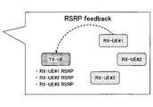
- FIG. 13 is a diagram showing an example in which open-loop transmission power control based on the path loss of the side link is performed for the group cast communication of the side link of NR.
- the open-loop transmission power control based on the side link for example, the receiving terminal 20 farthest from the transmitting terminal 20, that is, the side in the group. It is possible to control the transmission power so that the receiving-side terminal 20 having the maximum link path loss value can receive the radio signal from the transmitting-side terminal 20. Further, in the group, the receiving side terminal 20 having the maximum side link path loss value becomes a value larger than the value of the transmitting power necessary and sufficient to receive the radio signal from the transmitting side terminal 20. Since the transmission power is not set, it is possible to reduce interference with other groups. However, as the number of terminals 20 in the group increases, as shown in FIG. 13, more measurement resources and more feedback resources are required accordingly.
- Conditions may be specified for selecting whether or not to apply open-loop transmission power control based on the path loss of the side link to the group cast communication of the side link of the NR.
- Option B1 In NR side-link group cast communication, when all RSRPs of the receiving terminal 20 in the group can be used by the transmitting terminal 20, the transmitting terminal 20 transmits an open loop based on the path loss of the side link. Power control may be applied. If the RSRP of at least one receiving side terminal 20 among the receiving side terminals 20 in the group cannot be used by the transmitting side terminal 20, the transmitting side terminal 20 transmits an open loop based on the path loss of the side link. Power control may be disabled. In this case, open-loop transmission power control based on the downlink path loss may be applied.
- the RSRP of the receiving terminal 20 may be enabled by the transmitting terminal 20 receiving the RSRP fed back from the receiving terminal 20, or the transmitting terminal 20 may be on the receiving side. It may be enabled by receiving the RS transmitted from the terminal 20 and having the transmitting terminal 20 measure the RSRP.
- the transmission power control can be applied only when the open-loop transmission power control based on the side link path loss is effective.
- ACK group cast Acknowledgement
- NACK Negative-Acknowledgement
- the transmitting terminal 20 transmits an open loop based on the side link path loss. Power control may be applied.
- the transmitting terminal 20 does not have to apply open-loop transmission power control based on the side link path loss.
- the receiving terminal 20 transmits ACK and the transport block decoding fails.
- the receiving terminal 20 may mean transmitting NACK. That is, the fact that the ACK / NACK feedback of the group cast is valid means that higher reliability for communication is required and / or the number of terminals 20 in the group is small. Therefore, when the ACK / NACK feedback of the group cast is valid, it is assumed that it is desirable to further improve the reliability of communication by applying the open-loop transmission power control based on the path loss of the side link. If group cast ACK / NACK feedback is disabled, it may not be necessary to apply open-loop transmit power control based on sidelink path loss.
- group cast Acknowledgement (ACK) / Negative-Acknowledgement (NACK) feedback may be replaced with "group cast HARQ-ACK feedback”.
- the HARQ-ACK feedback of the group cast may include at least one of the following two methods. 1. 1. When the transport block is successfully decoded, the receiving terminal 20 transmits an ACK, and when the transport block decoding fails, the receiving terminal 20 transmits an NACK. 2. 2. If the decoding of the transport block is successful, the receiving terminal 20 does not transmit ACK and NACK, and if the decoding of the transport block fails, the receiving terminal 20 transmits NACK.
- the terminal 20 device on the transmitting side determines whether or not to apply the open-loop transmission power control based on the path loss of the side link according to the number of terminals 20 in the group. May be good. For example, if the number of terminals 20 in the group is less than (or less than or equal to) the threshold X, the transmitting terminal 20 device may apply open-loop transmission power control based on sidelink path loss. Good. If the number of terminals 20 in the group is greater than or equal to the threshold X (or greater than X), the transmitting terminal 20 device may not apply open-loop transmit power control based on sidelink path loss. ..
- the threshold value X may be specified by specifications, may be set (in advance) by the network, and may be set by a PC5-RRC message transmitted by another terminal 20 which is RRC signaling on the side link. It may be specified or determined based on the resource pool settings and / or may be specified based on the congestion level.
- HARQ Hybrid Automatic Repeat Request
- the transmitting terminal 20 device performs open-loop transmission based on the path loss of the side link. Power control may be applied. If the RSRP of the receiving terminal 20 performing HARQ feedback is not available on the transmitting terminal 20, the transmitting terminal 20 device may not apply open-loop transmit power control based on sidelink path loss. ..
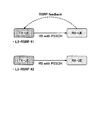
- FIG. 14 is a diagram showing an example in which open-loop transmission power control based on the path loss of the side link is applied when the distance-based HARQ is applied. It is assumed that the receiving terminal 20 for which HARQ feedback is valid is required to have high reliability for communication. Therefore, it is possible to improve the reliability of communication by acquiring the RSRP of the receiving terminal 20 for which HARQ feedback is valid and then applying the open-loop transmission power control based on the path loss of the side link. It becomes.
- the RSRP of the receiving terminal 20 may be enabled by the transmitting terminal 20 receiving the RSRP fed back from the receiving terminal 20, or the transmitting terminal 20 may be on the receiving side.
- the HARQ feedback is effective on the receiving side terminal 20.
- the threshold value Y may be specified by specifications, may be set (in advance) by the network, and may be set by a PC5-RRC message transmitted by another terminal 20 which is RRC signaling on the side link. It may be specified based on the resource pool settings and / or the congestion level.
- the open-loop transmission power control based on the path loss of the side link is applied only to the receiving terminal 20 that requires high reliability for communication, thereby receiving the reception. It is possible to improve the reliability of communication with the terminal 20 on the side.
- RSRP of the receiving terminal 20 may be enabled by the transmitting terminal 20 receiving the RSRP fed back from the receiving terminal 20, or the transmitting terminal 20 may be on the receiving side. It may be enabled by receiving the RS transmitted from the terminal 20 and having the transmitting terminal 20 measure the RSRP.
- the open-loop transmission power control based on the path loss of the side link is applied only to the terminal 20 which is expected to receive the group cast transmission. It is possible to improve the reliability of communication with.
- At least two of the above options B1 to B5 may be combined. For example, if the conditions of option B1 and option B2 are satisfied, the terminal 20 device on the transmitting side may apply open-loop transmission power control based on the path loss of the side link. In other cases, the transmitting terminal 20 device does not have to apply open-loop transmission power control based on the side link path loss. Alternatively, for example, if the conditions of option B1 or option B2 are satisfied, the transmitting terminal 20 device may apply open-loop transmission power control based on the path loss of the side link. In other cases, the transmitting terminal 20 device does not have to apply open-loop transmission power control based on the side link path loss.
- RSRP may be replaced with at least one of path loss, RSRQ, and CSI, or may be information related to communication quality between the transmitting side terminal 20 and the receiving side terminal 20.
- RSRP can be used by the transmitting terminal 20 means that the transmitting terminal 20 has received and / or acquired the RSRP and / or any signal for obtaining the RSRP. It may mean.
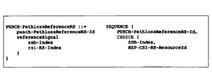
- FIG. 15 is a diagram showing an example in which path loss is measured with a reference signal based on the parameter PUSCH-PathlossRefenceRS of the upper layer.
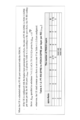
- 16 is a diagram showing an example of a PUSCH-PathlossRefenceRS information element. As shown in FIG. 16, the information element called referenceSignal is included in the PUSCH-PathlossRefenceRS information element, and it is possible to set ssb-Index or csi-RS-Index.
- the terminal 20 In the NR side link communication, there may be a terminal 20 that does not transmit the side link SSB. Therefore, it is not assumed that the side link SSB is applied as a reference signal for measuring the side link path loss in the NR side link communication. Further, in the side link communication of NR, it is not assumed that the terminal 20 transmits CSI-RS standalone. That is, transmission of only CSI-RS is not allowed, and CSI-RS is transmitted at the same time as transmission data and the like.
- the index or port of the DM-RS of the side link that can be used to measure the path loss of the side link may be specified by the specification, or may be set (in advance) as an upper layer parameter or the like. , It may be set by a PC5-RRC message transmitted by another terminal 20 which is RRC signaling on a side link, and / or may be specified by a network and / or another terminal 20. Alternatively, it may be possible to use all DM-RS ports used for sidelink communication to measure sidelink path loss.
- Option C2 In NR sidelink communication, only the sidelink CSI-RS may be used as a reference signal for measuring the sidelink path loss.
- the CSI-RS index or port of the side link that can be used to measure the path loss of the side link may be specified by the specification, may be set (in advance) by the network, and the side link may be set. It may be set by the PC5-RRC message transmitted by the other terminal 20 which is the RRC signaling in, and / or may be specified by the network. Alternatively, it may be possible to use all CSI-RS ports used for sidelink communication for measuring sidelink path loss.
- Option C3 In NR sidelink communication, it is possible to use the sidelink DM-RS as a reference signal for measuring the sidelink path loss, and additionally, the sidelink CSI-RS is used. It may be possible. Here, the use of the side link CSI-RS may depend on the implementation of the terminal 20.
- the DM-RS index or port of the side link that can be used to measure the path loss of the side link may be specified by the specification, may be set (in advance) by the network, and the side link may be set. It may be set by the PC5-RRC message transmitted by the other terminal 20 which is the RRC signaling in, and / or may be specified by the network. Alternatively, it may be possible to use all DM-RS ports used for sidelink communication to measure sidelink path loss.
- Option C4 In NR sidelink communication, it is possible to use the sidelink CSI-RS as a reference signal for measuring the sidelink path loss, and additionally, the sidelink DM-RS is used. It may be possible. Here, the use of the side link DM-RS may depend on the implementation of the terminal 20.
- the CSI-RS index or port of the side link that can be used to measure the path loss of the side link may be specified by the specification, may be set (in advance) by the network, and the side link may be set. It may be set by the PC5-RRC message transmitted by the other terminal 20 which is the RRC signaling in, and / or may be specified by the network. Alternatively, it may be possible to use all CSI-RS ports used for sidelink communication for measuring sidelink path loss.
- the sidelink SSB associated with the PSCH and / or the sidelink CSI-RS and / or the sidelink DM-RS are PSCCH / PSCH / PSFCH path loss reference signals (passloss) transmitted from the transmitting terminal 20.
- a reference RS and / or as a PSCCH / PSCH / PSFCH path loss reference signal (pathloss reference RS) transmitted from the receiving terminal 20, it may be specified by the specification and is set (in advance) by the network. It may be set by a PC5-RRC message transmitted by another terminal 20 which is RRC signaling on the side link.
- the path loss reference signal is not specified by the specifications, is not set (in advance) by the network, and is not set by the PC5-RRC message transmitted by the other terminal 20 which is the RRC signaling on the side link.
- the path loss reference signal may be any of the following options Ci to Cv.
- the DM-RS and / or CSI-RS used for broadcast transmission, or the DM-RS and / or CSI-RS used for sidelink transmission before the PC5-RRC connection is made can also be used as a path loss reference signal. Good.
- All received DM-RS and / or CSI-RS may be used as path loss reference signals.
- DM-RS and / or CSI-RS transmitted from a specific terminal 20 may be used as a path loss reference signal.
- Option Cii For a sidelink channel, if the TCI status is set (in advance) by the network, if it is set by a PC5-RRC message sent by another terminal 20 that is an RRC signaling on the sidelink, or specified. If so, the QCL type-A RS and / or the QCL type-B RS and / or the QCL type-C RS and / or the QCL type-D RS associated with the TCI state may be used as the path loss reference signal.
- FIG. 17 is a diagram showing an example of correspondence between the TCI state and the reference signal.
- the open-loop transmission power control based on the side link path loss may be disabled and / or the downlink open-loop transmission power control may be enabled.
- DM-RS and / or CSI-RS specified for L1-RSRP and / or L3-RSRP measurements may be used as the path loss reference signal.
- DM-configured (pre-) for L1-RSRP and / or L3-RSRP measurements RS and / or CSI-RS, or DM-RS and / or CSI-RS set by the PC5-RRC message for L1-RSRP measurement and / or L3-RSRP measurement may be used as the path loss reference signal.
- Terminal 20 may make RSRP measurements only if the RS is transmitted from a single RS port or if the RS is transmitted from a single CDM group.
- the terminal 20 may measure RSRP regardless of the number of RS ports.
- the RSRP calculation takes into account the number of RS ports and / or the power transmitted from each port.
- -Case1 When the number of RS ports is multiple and the total transmission power is the same as the transmission power in the case of a single RS port, the instantaneous RSRP P1 is RSRP, P2, P3, etc. from each RS port. It may be calculated by taking the sum of .. Alternatively, the instantaneous PSPR P1 may be calculated by multiplying the RSRP and P2 from one RS port by the number of RS ports.
- the instantaneous PSPR P1 is the RSRP from each RS port. It may be calculated by subtracting ZdB from the sum of P2, P3, .... Alternatively, the instantaneous PSPR P1 may be calculated by multiplying RSRP and P2 from one RS port by the number of RS ports and then subtracting ZdB from the result.
- the total transmit power is always specified (or determined, set) to be equal to the transmit power from a single RS port. May be good.
- the terminal 20 may perform the RSRP measurement only when the reference signal and the PSCH data are frequency-division-multiplexed, or only when the reference signal and the PSCH data are not frequency-division-multiplexed.
- the terminal 20 may measure RSRP regardless of whether the reference signal and the PSCH data are frequency-division-multiplexed.
- the terminal 20 may perform RSRP correction based on the case where the reference signal is not frequency-division-multiplexed with the PSSCH data.
- the terminal 20 may perform RSRP correction based on the case where the reference signal is frequency divided and multiplexed with the PSCH data.
- Whether or not to divide the frequency between the reference signal and the PSCH data may be specified by specifications, may be set (in advance) by the network, and other terminals that are RRC signaling on the side link. It may be set by the PC5-RRC message transmitted by 20 and may be specified by DCI and / or SCI.
- the PSCH data may mean a transport block transmitted by the PSCH, a CSI, or other information transmitted by the PSCH. You may.
- the transmitting side terminal 20 it is possible for the transmitting side terminal 20 to recognize how the receiving side terminal 20 performs RSRP measurement / calculation, and therefore, the transmitting side terminal 20 can recognize. , It becomes possible to calculate the path loss appropriately.
- the path loss reference signal may be L1-RSRP and / or L3-RSRP measurement, or may be a reference signal for measuring L1-RSRP and / or L3-RSRP. It may be a reference signal for measuring path loss, or it may be a reference signal for open-loop transmission power control.
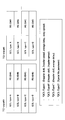
- FIG. 18 is a diagram showing an example of two methods for the transmitting terminal 20 to acquire the L3-RSRP measurement result.
- the transmitting terminal 20 transmits RS with PSCH data (for example, transport block and / or CSI) to the receiving terminal 20 and obtains RSRP feedback from the receiving terminal 20.
- the measurement result of L3-RSRP may be acquired.
- the transmitting terminal 20 receives an RS with PSCCH data (eg, transport block and / or CSI) transmitted from the receiving terminal 20 and performs an L3-RSRP based on the received RS. It may be calculated.
- PSCCH data eg, transport block and / or CSI
- the transmitting side terminal 20 can perform open-loop transmission power control based on the L3-RSRP measurement result fed back from the receiving side terminal 20, and the transmitting side terminal 20 calculates the power. It is also possible to perform open-loop transmission power control based on L3-RSRP. In this way, the transmission side terminal 20 may specify the proper use of the feedback L3-RSRP and the L3-RSRP calculated by the transmission side terminal 20 itself. In the following, the fed-back L3-RSRP may be replaced with the L3-RSRP based on the fed-back power information (for example, L1-RSRP).
- the transmitting terminal 20 may use both the L3-RSRP fed back from the receiving terminal 20 and the L3-RSRP calculated by the transmitting terminal 20 itself.
- L3-RSRP fed back from the receiving terminal 20 and L3-RSRP calculated by the transmitting terminal 20 itself may be preferentially used.
- the transmitting terminal 20 uses the L3-RSRP fed back from the receiving terminal 20 and the L3- calculated by the transmitting terminal 20 itself.
- L3-RSRP fed back from the terminal 20 on the receiving side may be used.
- the transmitting side L3-RSRP calculated by the terminal 20 itself may be used.
- the transmitting terminal 20 may use the L3-RSRP fed back from the receiving terminal 20 by averaging the L3-RSRP calculated by the transmitting terminal 20 itself. When averaging, weighting may be performed as appropriate. How to use the L3-RSRP fed back from the receiving terminal 20 and the L3-RSRP calculated by the transmitting terminal 20 itself may depend on the implementation of the terminal 20.
- the transmitting terminal 20 may use only the L3-RSRP fed back from the receiving terminal 20. In this case, it is not necessary for the transmitting terminal 20 to assume that the L3-RSRP calculated by the transmitting terminal 20 itself is used for the transmission power control of the transmitting terminal 20 itself.
- At least two of the above options 1 to 3 may be specified, and any one of the options may be set (in advance) by the network, and RRC at the side link. It may be set by a PC5-RRC message transmitted by another terminal 20 which is signaling, or may be specified by a network.
- the open-loop transmission power control is performed by defining the proper use of the L3-RSRP fed back and the L3-RSRP calculated by the transmitting terminal 20 itself in the transmitting terminal 20.
- the operation of the terminal 20 at the time is clarified.
- FIG. 19 is a diagram showing an example of the functional configuration of the base station 10.
- the base station 10 has a transmitting unit 101, a receiving unit 102, and a control unit 103.
- the functional configuration shown in FIG. 19 is only an example. Any function classification and name of the functional unit may be used as long as the operation according to the present embodiment can be executed.
- the transmitter 101 may be referred to as a transmitter, and the receiver 102 may be referred to as a receiver.
- the transmission unit 101 includes a function of generating a signal to be transmitted to the terminal 20 side and transmitting the signal wirelessly.
- the receiving unit 102 includes a function of receiving various signals transmitted from the terminal 20 and acquiring, for example, information of a higher layer from the received signals.
- the receiving unit 102 includes a function of measuring the received signal and acquiring a quality value.
- the control unit 103 controls the base station 10.
- the function of the control unit 103 related to transmission may be included in the transmission unit 101, and the function of the control unit 103 related to reception may be included in the reception unit 102.
- the control unit 103 of the base station 10 controls only the path loss of the downlink (DL: between the terminal 20 on the transmitting side and the base station 10 (gNB)) for the open loop transmission power control of the side link of the NR.
- DL between the terminal 20 on the transmitting side and the base station 10 (gNB)
- gNB base station 10
- a signal including the command may be transmitted to the terminal 20.
- control unit 103 of the base station 10 determines that the terminal 20 boosts the transmission power of the CSI-RS and / or the PT-RS, and increases the transmission power of the CSI-RS and / or
- the increase amount of the transmission power of the PT-RS (for example, the value of ⁇ and / or the value of ⁇ ) is set, and the transmission unit 101 terminals a signal including the increase amount (value of ⁇ and / or ⁇ ). It may be transmitted to 20.
- control unit 103 of the base station 10 determines whether or not to apply the open-loop transmission power control based on the path loss of the side link in the group cast communication of the side link of the NR, and the terminal 20 in the group.
- a threshold value X may be set for the number of the above, and the transmission unit 101 may transmit a signal including the threshold value X to the terminal 20.
- control unit 103 of the base station 10 sets the port or index of the DM-RS or CSI-RS of the side link that can be used to measure the path loss of the side link, and the transmission unit 101 sets the port or the index.
- a signal including the index may be transmitted to the terminal 20.
- the control unit 103 of the base station 10 transmits the SSB of the side link associated with the PSCH and / or the CSI-RS of the side link and / or the DM-RS of the side link from the terminal 20 on the transmitting side. It may be set as a path loss reference signal (pass loss reference RS) of PSCCH / PSCH / PSFCH and / or as a path loss reference signal (path loss reference RS) of PSCCH / PSCH / PSFCH transmitted from the receiving terminal 20. , The transmission unit 101 may transmit a signal including the setting information to the terminal 20.
- a path loss reference signal path loss reference signal
- path loss reference RS path loss reference signal
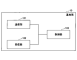
- FIG. 20 is a diagram showing an example of the functional configuration of the terminal 20.
- the terminal 20 has a transmission unit 201, a reception unit 202, and a control unit 203.
- the functional configuration shown in FIG. 20 is only an example. Any function classification and name of the functional unit may be used as long as the operation according to the present embodiment can be executed.
- the transmitter 201 may be referred to as a transmitter, and the receiver 202 may be referred to as a receiver.
- the terminal 20 may be the terminal 20A on the transmitting side or the terminal 20B on the receiving side. Further, the terminal 20 may be a scheduling terminal 20.
- the transmission unit 201 creates a transmission signal from the transmission data and wirelessly transmits the transmission signal.
- the receiving unit 202 wirelessly receives various signals and acquires a signal of a higher layer from the received signal of the physical layer. Further, the receiving unit 202 includes a function of measuring the received signal and acquiring the quality value.
- the control unit 203 controls the terminal 20.
- the function of the control unit 203 related to transmission may be included in the transmission unit 201, and the function of the control unit 203 related to reception may be included in the reception unit 202.
- control unit 203 of the terminal 20 may be able to set the value of the transmission power of the CSI-RS associated with the PSCCH to a value different from the value of the transmission power assigned to the PSCCH. Further, the control unit 203 of the terminal 20 may be able to set the value of the transmission power of the PT-RS associated with the PSCH to a value different from the value of the transmission power assigned to the PSCH.
- the receiving unit 202 of the terminal 20 indicates information instructing that the transmission power of CSI-RS and / or PT-RS is boosted, and the amount of increase in the transmission power of CSI-RS and / or the transmission power of PT-RS.
- the control unit 203 is based on the amount of increase (value of ⁇ and / or ⁇ ) received by the receiving unit 202. Therefore, the transmission power of CSI-RS and / or PT-RS may be boosted.
- control unit 203 of the terminal 20 may set the transmission power of the CSI-RS and / or the PT-RS associated with the PSCH so as to be always the same as the transmission power of the PSCH.
- control unit 203 of the terminal 20 may perform open-loop transmission power control based on the path loss of the side link for the group cast communication of the side link of the NR. Further, for example, the control unit 203 of the terminal 20 can use the RSRP of all the receiving terminals 20 in the group in the group cast communication of the side link of the NR, and the open-loop transmission power based on the path loss of the side link. Controls may be applied. Further, for example, the control unit 203 of the terminal 20 can use the open-loop transmission power based on the path loss of the side link when the RSRP of at least one receiving side terminal 20 among the receiving side terminals 20 in the group cannot be used. Control may be disabled.
- control unit 203 of the terminal 20 performs open-loop transmission power control based on the path loss of the side link when the ACK / NACK feedback of the group cast is enabled in the group cast communication of the side link of the NR. May be applied. Further, for example, the control unit 203 of the terminal 20 does not have to apply the open-loop transmission power control based on the path loss of the side link when the ACK / NACK readback of the group cast is invalidated.
- the control unit 203 of the terminal 20 determines that the number of terminals 20 in the group is smaller than the threshold value X or equal to or less than the threshold value X. Open-loop transmit power control based on path loss may be applied.
- control unit 203 of the terminal 20 opens based on the path loss of the side link when the RSRP of the receiving terminal 20 that must provide HARQ feedback can be used when the distance-based HARQ is applied.
- Loop transmission power control may be applied.
- control unit 203 of the terminal 20 uses the side link DM-RS and the side link CSI-RS as reference signals for measuring the side link path loss in the NR side link communication. You may choose to use at least one.
- control unit 203 of the transmitting side terminal 20 selects at least one of the L3-RSRP fed back from the receiving side terminal 20 and the L3-RSRP calculated by the transmitting side terminal 20 itself. , Open-loop transmission power control may be performed.
- each functional block may be realized by using one device that is physically or logically connected, or directly or indirectly (for example, by using two or more physically or logically separated devices). , Wired, wireless, etc.) and may be realized using these plurality of devices.
- the functional block may be realized by combining the software with the one device or the plurality of devices.
- Functions include judgment, decision, judgment, calculation, calculation, processing, derivation, investigation, search, confirmation, reception, transmission, output, access, solution, selection, selection, establishment, comparison, assumption, expectation, and assumption.
- broadcasting notifying, communicating, forwarding, configuring, reconfiguring, allocating, mapping, assigning, etc., but only these. I can't.
- a functional block (constituent unit) for functioning transmission is called a transmitting unit or a transmitter.
- the method of realizing each of them is not particularly limited.
- FIG. 21 is a diagram showing an example of the hardware configuration of the terminal 20 and the base station 10 according to the present embodiment.
- the terminal 20 and the base station 10 described above may be physically configured as a computer device including a processor 1001, a memory 1002, a storage 1003, a communication device 1004, an input device 1005, an output device 1006, a bus 1007, and the like. ..
- the word “device” can be read as a circuit, device, unit, etc.
- the hardware configuration of the terminal 20 and the base station 10 may be configured to include one or more of the devices shown in 1001 to 1006 shown in the figure, or may be configured not to include some of the devices. May be good.
- the processor 1001 For each function of the terminal 20 and the base station 10, by loading predetermined software (program) on hardware such as the processor 1001 and the memory 1002, the processor 1001 performs an operation and controls communication by the communication device 1004. , It is realized by controlling at least one of reading and writing of data in the memory 1002 and the storage 1003.
- the processor 1001 operates, for example, an operating system to control the entire computer.
- the processor 1001 may be configured by a central processing unit (CPU: Central Processing Unit) including an interface with a peripheral device, a control device, an arithmetic unit, a register, and the like.
- CPU Central Processing Unit
- the processor 1001 reads a program (program code), a software module, data, etc. from at least one of the storage 1003 and the communication device 1004 into the memory 1002, and executes various processes according to these.
- a program program code
- a program that causes a computer to execute at least a part of the operations described in the above-described embodiment is used.
- the control unit 203 of the terminal 20 may be realized by a control program stored in the memory 1002 and operating in the processor 1001, and may be realized in the same manner for other functional blocks.
- Processor 1001 may be implemented by one or more chips.
- the program may be transmitted from the network via a telecommunication line.
- the memory 1002 is a computer-readable recording medium, and is composed of at least one such as a ROM (Read Only Memory), an EPROM (Erasable Programmable ROM), an EEPROM (Electrically Erasable Programmable ROM), and a RAM (Random Access Memory). May be done.
- the memory 1002 may be referred to as a register, a cache, a main memory (main storage device), or the like.
- the memory 1002 can store a program (program code), a software module, or the like that can be executed to implement the wireless communication method according to the embodiment of the present disclosure.
- the storage 1003 is a computer-readable recording medium, and is, for example, an optical disk such as a CD-ROM (Compact Disc ROM), a hard disk drive, a flexible disk, a photomagnetic disk (for example, a compact disk, a digital versatile disk, or a Blu-ray). It may consist of at least one (registered trademark) disk), smart card, flash memory (eg, card, stick, key drive), floppy (registered trademark) disk, magnetic strip, and the like.
- the storage 1003 may be referred to as an auxiliary storage device.
- the storage medium described above may be, for example, a database, server or other suitable medium containing at least one of memory 1002 and storage 1003.
- the communication device 1004 is hardware (transmission / reception device) for communicating between computers via at least one of a wired network and a wireless network, and is also referred to as, for example, a network device, a network controller, a network card, a communication module, or the like.
- the communication device 1004 includes, for example, a high frequency switch, a duplexer, a filter, a frequency synthesizer, and the like in order to realize at least one of frequency division duplex (FDD: Frequency Division Duplex) and time division duplex (TDD: Time Division Duplex). It may be composed of.
- FDD Frequency Division Duplex
- TDD Time Division Duplex
- the input device 1005 is an input device (for example, a keyboard, a mouse, a microphone, a switch, a button, a sensor, etc.) that receives an input from the outside.
- the output device 1006 is an output device (for example, a display, a speaker, an LED lamp, etc.) that outputs to the outside.
- the input device 1005 and the output device 1006 may have an integrated configuration (for example, a touch panel).
- each device such as the processor 1001 and the memory 1002 is connected by the bus 1007 for communicating information.
- the bus 1007 may be configured by using a single bus, or may be configured by using a different bus for each device.
- the terminal 20 and the base station 10 are hardware such as a microprocessor, a digital signal processor (DSP: Digital Signal Processor), an ASIC (Application Specific Integrated Circuit), a PLD (Programmable Logic Device), and an FPGA (Field Programmable Gate Array), respectively. It may be configured to include hardware, and a part or all of each functional block may be realized by the hardware. For example, processor 1001 may be implemented using at least one of these hardware.
- the transmission power for transmitting the reference signal is the first.
- a control unit that sets one value to the same value as or different from the second value of the transmission power for transmitting the data, and the first value of the transmission power applied to the reference signal, and said A terminal including a reference signal and a transmission unit that transmits the data by applying a second value of transmission power to the data.
- the first value of the transmission power for transmitting the reference signal is determined based on the first ratio occupied by the reference signal in the symbol, and is the second of the transmission power for transmitting the data.
- the value of may be determined based on the second percentage of the data in the symbol. According to the above configuration, the control when boosting the transmission power of the reference signal is clarified.
- the control unit further includes a receiving unit that receives a signal instructing that the first value is set to the same value as or different from the second value, and the control unit follows the instruction of the signal received by the receiving unit.
- the first value may be set to the same value as or different from the second value.
- the CSI-RS transmission power is boosted, and when the CSI-RS resource is high, the CSI-RS transmission power is set to PSCH. It is possible to operate by setting the same value as the transmission power assigned to.
- the control unit may map the reference signal and the control signal of the side link to the radio resource so that the reference signal and the control signal of the side link do not overlap in the time domain.
- the mathematical formula for controlling the transmission power may be complicated, and the implementation of the device may be complicated. According to the above configuration, it is possible to avoid complicated mathematical formulas and complicated device implementation.
- the control unit may always set the first value to the same value as the second value.
- the transmission power for transmitting the reference signal is the first.
- a terminal-based communication method comprising applying a second value of power to the data and transmitting the reference signal and the data.
- the operation of the plurality of functional units may be physically performed by one component, or the operation of one functional unit may be physically performed by a plurality of components.
- the order of processing may be changed as long as there is no contradiction.
- the terminal 20 and the base station 10 have been described with reference to functional block diagrams, but such devices may be implemented in hardware, software, or a combination thereof.
- the software operated by the processor of the terminal 20 according to the embodiment of the present invention and the software operated by the processor of the base station 10 according to the embodiment of the present invention are random access memory (RAM), flash memory, and read-only memory, respectively. It may be stored in (ROM), EPROM, EEPROM, registers, hard disk (HDD), removable disk, CD-ROM, database, server or any other suitable storage medium.
- information notification includes physical layer signaling (for example, DCI (Downlink Control Information), UCI (Uplink Control Information)), higher layer signaling (for example, RRC (Radio Resource Control) signaling, MAC (Medium Access Control) signaling, etc. It may be carried out by notification information (MIB (Master Information Block), SIB (System Information Block)), other signals, or a combination thereof.
- RRC signaling may be called an RRC message, and may be, for example, an RRC connection setup (RRC Connection Setup) message, an RRC connection reconfiguration (RRC Connection Reconfiguration) message, or the like.
- Each aspect / embodiment described in the present disclosure includes LTE (Long Term Evolution), LTE-A (LTE-Advanced), SUPER 3G, IMT-Advanced, 4G (4th generation mobile communication system), and 5G (5th generation mobile communication).
- system FRA (Future Radio Access), NR (new Radio), W-CDMA (registered trademark), GSM (registered trademark), CDMA2000, UMB (Ultra Mobile Broadband), IEEE 802.11 (Wi-Fi (registered trademark)) )), LTE 802.16 (WiMAX®), IEEE 802.20, UWB (Ultra-WideBand), Bluetooth®, and other systems that utilize suitable systems and have been extended based on these. It may be applied to at least one of the next generation systems. Further, a plurality of systems may be applied in combination (for example, a combination of at least one of LTE and LTE-A and 5G).
- the specific operation performed by the base station 10 in the present disclosure may be performed by its upper node (upper node).
- various operations performed for communication with a terminal are performed by the base station 10 and other network nodes other than the base station 10 (for example,). , MME, S-GW, and the like, but not limited to these).
- MME Mobility Management Entity
- S-GW Packet Control Function
- the case where there is one network node other than the base station 10 is illustrated above, it may be a combination of a plurality of other network nodes (for example, MME and S-GW).
- the input / output information and the like may be stored in a specific location (for example, memory) or may be managed using a management table. Input / output information and the like can be overwritten, updated, or added. The output information and the like may be deleted. The input information or the like may be transmitted to another device.
- the determination may be made by a value represented by 1 bit (0 or 1), by a boolean value (Boolean: true or false), or by comparing numerical values (for example, a predetermined value). It may be done by comparison with the value).
- the notification of predetermined information (for example, the notification of "being X") is not limited to the explicit one, but is performed implicitly (for example, the notification of the predetermined information is not performed). May be good.
- Software is an instruction, instruction set, code, code segment, program code, program, subprogram, software module, whether called software, firmware, middleware, microcode, hardware description language, or another name.
- Applications, software applications, software packages, routines, subroutines, objects, executables, execution threads, procedures, features, etc. should be broadly interpreted to mean.
- software, instructions, information, etc. may be transmitted and received via a transmission medium.
- a transmission medium For example, a website that uses at least one of wired technology (coaxial cable, fiber optic cable, twist pair, digital subscriber line (DSL: Digital Subscriber Line), etc.) and wireless technology (infrared, microwave, etc.) When transmitted from a server, or other remote source, at least one of these wired and wireless technologies is included within the definition of transmission medium.
- the information, signals, etc. described in this disclosure may be represented using any of a variety of different techniques.
- data, instructions, commands, information, signals, bits, symbols, chips, etc. that may be referred to throughout the above description are voltages, currents, electromagnetic waves, magnetic fields or magnetic particles, light fields or photons, or any of these. It may be represented by a combination of.
- At least one of a channel and a symbol may be a signal (signaling).
- the signal may be a message.
- system and “network” used in this disclosure are used interchangeably.
- information, parameters, etc. described in the present disclosure may be expressed using absolute values, relative values from predetermined values, or using other corresponding information. It may be represented.
- the radio resource may be one indicated by an index.
- base station Base Station
- wireless base station fixed station
- NodeB NodeB
- eNodeB eNodeB
- gNodeB gNodeB
- Base stations are sometimes referred to by terms such as macrocells, small cells, femtocells, and picocells.
- the base station can accommodate one or more (for example, three) cells.
- a base station accommodates multiple cells, the entire coverage area of the base station can be divided into multiple smaller areas, each smaller area being a base station subsystem (eg, a small indoor base station (RRH:)).
- Communication services can also be provided by (Remote Radio Head).
- the term "cell” or “sector” is a part or all of the coverage area of at least one of the base station and the base station subsystem that provides the communication service in this coverage. Point to.
- MS Mobile Station
- UE User Equipment
- Mobile stations can be subscriber stations, mobile units, subscriber units, wireless units, remote units, mobile devices, wireless devices, wireless communication devices, remote devices, mobile subscriber stations, access terminals, mobile terminals, wireless, depending on the trader. It may also be referred to as a terminal, remote terminal, handset, user agent, mobile client, client, or some other suitable term.
- At least one of the base station and the mobile station may be called a transmitting device, a receiving device, a terminal, or the like. At least one of the base station and the mobile station may be a device mounted on the mobile body, the mobile body itself, or the like.
- the moving body may be a vehicle (eg, car, airplane, etc.), an unmanned moving body (eg, drone, self-driving car, etc.), or a robot (manned or unmanned). ) May be.
- at least one of the base station and the mobile station includes a device that does not necessarily move during communication operation.
- at least one of the base station and the mobile station may be an IoT (Internet of Things) device such as a sensor.
- IoT Internet of Things
- the base station in the present disclosure may be read by the user terminal.
- the communication between the base station and the user terminal is replaced with the communication between a plurality of user terminals (for example, it may be called D2D (Device-to-Device), V2X (Vehicle-to-Everything), etc.).
- D2D Device-to-Device
- V2X Vehicle-to-Everything
- Each aspect / embodiment of the present disclosure may be applied to the configuration.
- the user terminal 20 may have the function of the base station 10 described above.
- words such as "up” and “down” may be read as words corresponding to communication between terminals (for example, "side”).
- the uplink, downlink, and the like may be read as side channels.
- the user terminal in the present disclosure may be read as a base station.
- the base station 10 may have the functions of the user terminal 20 described above.
- connection means any direct or indirect connection or connection between two or more elements, and each other. It can include the presence of one or more intermediate elements between two “connected” or “combined” elements.
- the connection or connection between the elements may be physical, logical, or a combination thereof.
- connection may be read as "access”.
- the two elements use at least one of one or more wires, cables and printed electrical connections, and, as some non-limiting and non-comprehensive examples, the radio frequency domain. Can be considered to be “connected” or “coupled” to each other using electromagnetic energies having wavelengths in the microwave and light (both visible and invisible) regions.
- the reference signal may be abbreviated as RS (Reference Signal), and may be called a pilot depending on the applicable standard.
- the radio frame may be composed of one or more frames in the time domain. Each one or more frames in the time domain may be referred to as a subframe. Subframes may further consist of one or more slots in the time domain.
- the subframe may have a fixed time length (eg, 1 ms) that is independent of numerology.
- the numerology may be a communication parameter that applies to at least one of the transmission and reception of a signal or channel.
- Numerology includes, for example, subcarrier interval (SCS: SubCarrier Spacing), bandwidth, symbol length, cyclic prefix length, transmission time interval (TTI: Transition Time Interval), number of symbols per TTI, wireless frame configuration, transmission / reception.
- SCS SubCarrier Spacing
- TTI Transmission Time Interval
- At least one of a specific filtering process performed by the machine in the frequency domain, a specific windowing process performed by the transmitter / receiver in the time domain, and the like may be indicated.
- the slot may be composed of one or more symbols in the time domain (OFDM (Orthogonal Frequency Division Multiplexing) symbol, SC-FDMA (Single Carrier Frequency Division Multiple Access) symbol, etc.). Slots may be unit of time based on numerology.
- OFDM Orthogonal Frequency Division Multiplexing
- SC-FDMA Single Carrier Frequency Division Multiple Access
- the slot may include a plurality of mini slots. Each minislot may consist of one or more symbols in the time domain. Further, the mini slot may be called a sub slot. A minislot may consist of a smaller number of symbols than the slot.
- a PDSCH (or PUSCH) transmitted in time units larger than the minislot may be referred to as a PDSCH (or PUSCH) mapping type A.
- the PDSCH (or PUSCH) transmitted using the minislot may be referred to as PDSCH (or PUSCH) mapping type B.
- the wireless frame, subframe, slot, mini slot and symbol all represent the time unit when transmitting a signal.
- the radio frame, subframe, slot, minislot and symbol may have different names corresponding to each.
- one subframe may be referred to as a transmission time interval (TTI)
- TTI transmission time interval
- TTI transmission time interval
- TTI transmission time interval
- TTI transmission time interval
- a plurality of consecutive subframes may be referred to as TTI
- TTI slot or one minislot
- You may. That is, at least one of the subframe and TTI may be a subframe (1 ms) in existing LTE, a period shorter than 1 ms (eg, 1-13 symbols), or a period longer than 1 ms. It may be.
- the unit representing TTI may be called a slot, a mini slot, or the like instead of a subframe.
- TTI refers to, for example, the minimum time unit of scheduling in wireless communication.
- the base station schedules each user terminal to allocate radio resources (frequency bandwidth that can be used in each user terminal, transmission power, etc.) in TTI units.
- the definition of TTI is not limited to this.
- the TTI may be a transmission time unit such as a channel-encoded data packet (transport block), a code block, or a code word, or may be a processing unit such as scheduling or link adaptation.
- the time interval for example, the number of symbols
- the transport block, code block, code word, etc. may be shorter than the TTI.
- one or more TTIs may be the minimum time unit for scheduling. Further, the number of slots (number of mini-slots) constituting the minimum time unit of the scheduling may be controlled.
- a TTI having a time length of 1 ms may be referred to as a normal TTI (TTI in LTE Rel. 8-12), a normal TTI, a long TTI, a normal subframe, a normal subframe, a long subframe, a slot, or the like.
- TTIs shorter than normal TTIs may be referred to as shortened TTIs, short TTIs, partial TTIs (partial or fractional TTIs), shortened subframes, short subframes, minislots, subslots, slots and the like.
- the long TTI (for example, normal TTI, subframe, etc.) may be read as a TTI having a time length of more than 1 ms, and the short TTI (for example, shortened TTI, etc.) is less than the TTI length of the long TTI and 1 ms. It may be read as a TTI having the above TTI length.
- the resource block (RB) is a resource allocation unit in the time domain and the frequency domain, and may include one or more consecutive subcarriers in the frequency domain.
- the number of subcarriers contained in the RB may be the same regardless of the numerology, and may be, for example, 12.
- the number of subcarriers contained in the RB may be determined based on numerology.
- the time domain of RB may include one or more symbols, and may have a length of 1 slot, 1 mini slot, 1 subframe, or 1 TTI.
- Each 1TTI, 1 subframe, etc. may be composed of one or a plurality of resource blocks.
- one or more RBs include a physical resource block (PRB: Physical RB), a subcarrier group (SCG: Sub-Carrier Group), a resource element group (REG: Resource Element Group), a PRB pair, an RB pair, and the like. May be called.
- PRB Physical resource block
- SCG Sub-Carrier Group
- REG Resource Element Group
- PRB pair an RB pair, and the like. May be called.
- the resource block may be composed of one or a plurality of resource elements (RE: Resource Elements).
- 1RE may be a radio resource area of 1 subcarrier and 1 symbol.
- the bandwidth portion (BWP: Bandwidth Part) (which may also be referred to as partial bandwidth) may represent a subset of consecutive common RBs (common resources blocks) for a certain neurology in a carrier. Good.
- the common RB may be specified by the index of the RB with respect to the common reference point of the carrier.
- PRBs may be defined in a BWP and numbered within that BWP.
- the BWP may include a BWP for UL (UL BWP) and a BWP for DL (DL BWP).
- UL BWP UL BWP
- DL BWP DL BWP
- One or more BWPs may be set in one carrier for the UE.
- At least one of the configured BWPs may be active, and the UE may not expect to send or receive a given signal / channel outside the active BWP.
- “cell”, “carrier” and the like in this disclosure may be read as “BWP”.
- the above-mentioned structures such as wireless frames, subframes, slots, mini slots and symbols are merely examples.
- the number of subframes contained in a wireless frame the number of slots per subframe or wireless frame, the number of minislots contained within a slot, the number of symbols and RBs contained in a slot or minislot, included in the RB.
- the number of subcarriers, the number of symbols in the TTI, the symbol length, the cyclic prefix (CP) length, and the like can be variously changed.
- the term "A and B are different” may mean “A and B are different from each other”.
- the term may mean that "A and B are different from C”.
- Terms such as “separate” and “combined” may be interpreted in the same way as “different”.
- Base station 20 Terminal 101 Transmitter 102 Receiver 103 Control unit 201 Transmitter 202 Receiver 203 Control unit 1001 Processor 1002 Memory 1003 Storage 1004 Communication device 1005 Input device 1006 Output device
Abstract
A terminal equipped with: a control unit for setting a first value of the transmission power for transmitting a reference signal so as to be the same as or different from a second value of the transmission power for transmitting data, when data and a sidelink reference signal to be transmitted in a sidelink shared channel are frequency-division multiplexed in a symbol mapping the sidelink shared channel; and a transmission unit which applies the first value of the transmission power to the reference signal, applies the second value of the transmission power to the data, and transmits the reference signal and the data.
Description
本発明は、無線通信システムにおける端末及び通信方法に関連する。
The present invention relates to terminals and communication methods in wireless communication systems.
LTE(Long Term Evolution)及びLTEの後継システム(例えば、LTE-A(LTE Advanced)、NR(New Radio)(5Gとも呼ぶ))では、User Equipment(UE)等の端末同士が基地局を介さないで直接通信を行うサイドリンク(D2D(Device to Device)とも呼ぶ)技術が検討されている。
In LTE (Long Term Evolution) and LTE successor systems (for example, LTE-A (LTE Advanced), NR (New Radio) (also called 5G)), terminals such as User Equipment (UE) do not go through a base station. Side link (also called D2D (Device to Device)) technology for direct communication is being studied.
また、V2X(Vehicle to Everything)を実現することが検討され、仕様化が進められている。ここで、V2Xとは、ITS(Intelligent Transport Systems)の一部であり、図1に示すように、自動車間で行われる通信形態を意味するV2V(Vehicle to Vehicle)、自動車と道路脇に設置される路側機(RSU:Road-Side Unit)との間で行われる通信形態を意味するV2I(Vehicle to Infrastructure)、自動車とドライバーのモバイル端末との間で行われる通信形態を意味するV2N(Vehicle to Nomadic device)、及び、自動車と歩行者のモバイル端末との間で行われる通信形態を意味するV2P(Vehicle to Pedestrian)の総称である。
In addition, it is being considered to realize V2X (Vehicle to Everything), and specifications are being promoted. Here, V2X is a part of ITS (Intelligent Transport Systems), and as shown in FIG. 1, V2V (Vehicle to Vehicle), which means a communication mode between automobiles, is installed on the side of an automobile and a road. V2I (Vehicle to Infrastructure), which means a communication mode between a vehicle and a road-side unit (RSU), and V2N (Vehicle to), which means a communication mode between a car and a driver's mobile terminal. Nomadic device) and V2P (Vehicle to Pedestrian), which means a communication mode between a car and a pedestrian mobile terminal.
New Radio(NR)のサイドリンク(SL)で、送信電力制御(power control)をサポートすることが想定されている。3GPPのリリース16では、開ループ送信電力制御(open-loop transmitter power control、OLPC)だけをサポートすることが想定されている。開ループ送信電力制御では、端末は基地局からの信号の受信電力を測定し、上り送信電力を決定する。
It is assumed that the side link (SL) of the New Radio (NR) will support transmission power control (power control). Release 16 of 3GPP is expected to support only open-loop transmission power control (open-loop transmitter power control, OLPC). In open-loop transmission power control, the terminal measures the received power of the signal from the base station to determine the uplink transmission power.
NRのサイドリンクの通信において、サイドリンクのChannel State Information Reference Signal(CSI-RS)の送信電力制御をどのように行うのか、現時点では規定されていない。また、NRのサイドリンクの通信において、サイドリンクのPhase Tracking Reference Signal(PTRS)の送信電力制御をどのように行うのか、現時点では規定されていない。これらのサイドリンクのリファレンス信号に対する送信電力制御を適切に行うことを可能とすることが必要とされている。
At present, it is not specified how to control the transmission power of the Channel State Information Reference Signal (CSI-RS) of the side link in the NR side link communication. Further, in the NR side link communication, how to control the transmission power of the side link Phase Tracking Reference Signal (PTRS) is not specified at present. It is necessary to be able to appropriately control the transmission power for the reference signals of these side links.
本発明の一態様によれば、サイドリンクの共有チャネルがマッピングされるシンボルにおいて、前記サイドリンクの共有チャネルで送信されるデータ及びサイドリンクのリファレンス信号が周波数分割多重される場合において、前記リファレンス信号を送信するための送信電力の第一の値を、前記データを送信するための送信電力の第二の値と同じ値又は異なる値に設定する制御部と、前記送信電力の第一の値を前記リファレンス信号に適用し、かつ前記送信電力の第二の値を前記データに適用して、前記リファレンス信号及び前記データを送信する送信部と、を備える端末、が提供される。
According to one aspect of the present invention, in the symbol to which the shared channel of the side link is mapped, the reference signal is frequency-division-multiplexed when the data transmitted on the shared channel of the side link and the reference signal of the side link are frequency-divided and multiplexed. A control unit that sets the first value of the transmission power for transmitting the data to the same value or a different value as the second value of the transmission power for transmitting the data, and the first value of the transmission power. Provided is a terminal comprising the reference signal and a transmission unit for transmitting the data by applying the second value of the transmission power to the data and applying the reference signal.
実施例によれば、サイドリンクのリファレンス信号に対する送信電力制御を適切に行うことが可能となる。
According to the embodiment, it is possible to appropriately control the transmission power for the side link reference signal.
以下、図面を参照して本発明の実施の形態(本実施の形態)を説明する。なお、以下で説明する実施の形態は一例に過ぎず、本発明が適用される実施の形態は、以下の実施の形態に限られるわけではない。
Hereinafter, an embodiment of the present invention (the present embodiment) will be described with reference to the drawings. The embodiments described below are merely examples, and the embodiments to which the present invention is applied are not limited to the following embodiments.
本実施の形態における端末間の直接通信の方式はLTEあるいはNRのサイドリンク(SL(Sidelink))であることを想定しているが、直接通信の方式は当該方式に限られない。また、「サイドリンク」という名称は一例であり、「サイドリンク」という名称が使用されずに、UL(Uplink)が、SLの機能を含むこととしてもよい。SLは、DL(Downlink)又はULと周波数又は時間リソースの違いによって区別されてもよく、他の名称であってもよい。
The method of direct communication between terminals in the present embodiment is assumed to be LTE or NR side link (SL (Sidelink)), but the method of direct communication is not limited to this method. Further, the name "side link" is an example, and the name "side link" may not be used, and UL (Uplink) may include the function of SL. SL may be distinguished from DL (Downlink) or UL by the difference in frequency or time resource, or may have another name.
また、ULとSLとが、時間リソース、周波数リソース、時間・周波数リソース、送信電力制御においてPathlossを決定するために参照する参照信号、同期するために使用する参照信号(PSS/SSS/PSSS/SSSS)のいずれか1つ又はいずれか複数の組み合わせの違いによって区別されてもよい。
Further, UL and SL refer to a time resource, a frequency resource, a time / frequency resource, a reference signal for determining Pathloss in transmission power control, and a reference signal (PSS / SSS / PSSS / SSSS) used for synchronization. ) May be distinguished by the difference in any one or a plurality of combinations.
例えば、ULでは、送信電力制御においてPathlossを決定するために参照する参照信号として、アンテナポートX_ANTの参照信号を使用し、SL(SLとして使用するULを含む)では、送信電力制御においてPathlossを決定するために参照する参照信号として、アンテナポートY_ANTの参照信号を使用する。
For example, in UL, the reference signal of antenna port X_ANT is used as a reference signal to be referred to in determining Pathloss in transmission power control, and in SL (including UL used as SL), Pathloss is determined in transmission power control. As the reference signal to be referred to, the reference signal of the antenna port Y_ANT is used.
また、本実施の形態では、端末(ユーザ装置(UE)と呼ばれてもよい)が車両に搭載される形態を主に想定しているが、本発明の実施形態は、この形態に限定されない。例えば、端末は人が保持する端末であってもよいし、端末がドローンあるいは航空機に搭載される装置であってもよいし、端末が基地局、RSU、中継局(リレーノード)、スケジューリング能力を有するユーザ装置等であってもよい。
Further, in the present embodiment, it is mainly assumed that a terminal (which may be called a user device (UE)) is mounted on a vehicle, but the embodiment of the present invention is not limited to this mode. .. For example, the terminal may be a terminal held by a person, the terminal may be a device mounted on a drone or an aircraft, and the terminal may be a base station, an RSU, a relay station (relay node), and a scheduling ability. It may be a user device or the like.
(サイドリンクの概要)
本実施の形態では、サイドリンクを基本技術とすることから、まず、基本的な例として、サイドリンクの概要について説明する。ここで説明する技術の例は3GPPのRel.14等で規定されている技術である。当該技術は、NRにおいて使用されてもよいし、NRでは、当該技術と異なる技術が使用されてもよい。ここで、サイドリンク通信は、E-UTRA技術を使用しながらネットワークノードを介さずに、隣接する2つ以上のユーザ装置間で行われる直接通信と定義されてもよい。サイドリンクは、サイドリンク通信におけるユーザ装置間のインタフェースと定義されてもよい。 (Outline of side link)
In the present embodiment, since the side link is used as the basic technology, first, the outline of the side link will be described as a basic example. An example of the technique described here is 3GPP Rel. This is the technology specified in 14 mag. The technique may be used in the NR, or a technique different from the technique may be used in the NR. Here, side-link communication may be defined as direct communication performed between two or more adjacent user devices while using E-UTRA technology without going through a network node. Sidelinks may be defined as interfaces between user devices in sidelink communication.
サイドリンクには、大きく分けて「ディスカバリ」と「コミュニケーション」がある。「ディスカバリ」については、図2Aに示すように、Discovery period毎に、Discoveryメッセージ用のリソースプールが設定(configured)され、端末(UEと称される)はそのリソースプール内でDiscoveryメッセージ(発見信号)を送信する。より詳細にはType1、Type2bがある。Type1では、端末が自律的にリソースプールから送信リソースを選択してもよい。Type2bでは、上位レイヤシグナリング(例えばRRC信号)により準静的なリソースが割り当てられてもよい(上位レイヤシグナリングに代えて、サイドリンクのRRCシグナリングであるPC5-RRCが適用されてもよく、DCI及び/又はSCIが適用されてもよい)。
Sidelinks are roughly divided into "discovery" and "communication". Regarding "discovery", as shown in FIG. 2A, a resource pool for Discovery messages is set (configured) for each Discovery period, and a terminal (referred to as UE) is a Discovery message (discovery signal) in the resource pool. ) Is sent. More specifically, there are Type1 and Type2b. In Type 1, the terminal may autonomously select a transmission resource from the resource pool. In Type2b, quasi-static resources may be allocated by higher layer signaling (eg, RRC signal) (instead of higher layer signaling, PC5-RRC, which is a sidelink RRC signaling, may be applied, DCI and / Or SCI may be applied).
「コミュニケーション」についても、図2Bに示すように、SC(Sidelink Control)period毎にSCI(Sidelink Control Information)/データ送信用のリソースプールが周期的に設定される。送信側の端末はControlリソースプール(PSCCHリソースプール)から選択されたリソースでSCIによりデータ送信用リソース(PSSCHリソースプール)等を受信側に通知し、当該データ送信用リソースでデータを送信する。「コミュニケーション」について、より詳細には、モード1とモード2がある。モード1では、基地局から端末に送られる(E)PDCCH((Enhanced) Physical Downlink Control Channel)によりダイナミックにリソースが割り当てられてもよい。モード2では、端末はリソースプールから自律的に送信リソースを選択してもよい。リソースプールについては、SIBで通知される等(SIBに代えて、MIB、上位レイヤシグナリング、サイドリンクのRRCシグナリングであるPC5-RRC等が適用されてもよい)、予め定義されたものが使用されてもよい。
As for "communication", as shown in FIG. 2B, a resource pool for SCI (Sidelink Control Information) / data transmission is periodically set for each SC (Sidelink Control) period. The terminal on the transmitting side notifies the receiving side of the data transmission resource (PSSCH resource pool) or the like by SCI with the resource selected from the Control resource pool (PSCCH resource pool), and transmits the data with the data transmission resource. More specifically, there are modes 1 and 2 for "communication". In mode 1, resources may be dynamically allocated by (E) PDCCH ((Enhanced) Physical Downlink Control Channel) sent from the base station to the terminal. In mode 2, the terminal may autonomously select a transmission resource from the resource pool. As for the resource pool, a predefined one is used, such as being notified by SIB (MIB, upper layer signaling, PC5-RRC which is RRC signaling of side link, etc. may be applied instead of SIB). You may.
また、Rel-14では、モード1とモード2に加えて、モード3とモード4がある。Rel-14では、SCIとデータとを同時に(1サブフレームで)、周波数方向に隣接したリソースブロックで送信することが可能である。なお、SCIをSA(scheduling assignment)と称する場合がある。
In addition, in Rel-14, in addition to mode 1 and mode 2, there are mode 3 and mode 4. In Rel-14, SCI and data can be transmitted simultaneously (in one subframe) in resource blocks adjacent in the frequency direction. In addition, SCI may be referred to as SA (scheduling association).
「ディスカバリ」に用いられるチャネルはPSDCH(Physical Sidelink Discovery Channel)と称され、「コミュニケーション」におけるSCI等の制御情報を送信するチャネルはPSCCH(Physical Sidelink Control Channel)と称され、データを送信するチャネルはPSSCH(Physical Sidelink Shared Channel)と称されてもよい。PSCCHとPSSCHはPUSCHベースの構造を有し、DMRS(Demodulation Reference Signal、復調参照信号)が挿入される構造とされてもよい。なお、本明細書において、PSCCHをサイドリンクの制御チャネルと称してもよく、PSSCHをサイドリンクの共有チャネルと称してもよい。PSCCHを介して送信される信号をサイドリンクの制御信号と称してもよく、PSSCHを介して送信される信号をサイドリンクのデータ信号と称してもよい。
The channel used for "discovery" is called PSDCH (Physical Sidelink Discovery Channel), the channel for transmitting control information such as SCI in "communication" is called PSCCH (Physical Sidelink Control Channel), and the channel for transmitting data is called PSCCH (Physical Sidelink Control Channel). It may be referred to as PSCH (Physical Sidelink Shared Channel). The PSCCH and the PSSCH have a PUSCH-based structure, and may have a structure in which a DMRS (Demodulation Reference Signal, demodulation reference signal) is inserted. In this specification, PSCCH may be referred to as a side link control channel, and PSCCH may be referred to as a side link shared channel. The signal transmitted via the PSCCH may be referred to as a sidelink control signal, and the signal transmitted via the PSCCH may be referred to as a sidelink data signal.
サイドリンクに用いられるMAC(Medium Access Control)PDU(Protocol Data Unit)は、図3に示すように、少なくともMAC header、MAC Control element、MAC SDU(Service Data Unit)、Paddingで構成されてもよい。MAC PDUはその他の情報を含んでも良い。MAC headerは、1つのSL-SCH(Sidelink Shared Channel)subheaderと、1つ以上のMAC PDU subheaderで構成されてもよい。
As shown in FIG. 3, the MAC (Medium Access Control) PDU (Protocol Data Unit) used for the side link may be composed of at least a MAC header, a MAC Control element, a MAC SDU (Service Data Unit), and Padding. The MAC PDU may contain other information. The MAC header may be composed of one SL-SCH (Sidelink Sharped Channel) subheader and one or more MAC PDU subheaders.
図4に示すように、SL-SCH subheaderは、MAC PDUフォーマットバージョン(V)、送信元情報(SRC)、送信先情報(DST)、Reserved bit(R)等で構成されてもよい。Vは、SL-SCH subheaderの先頭に割り当てられ、端末が用いるMAC PDUフォーマットバージョンを示してもよい。送信元情報には、送信元に関する情報が設定されてもよい。送信元情報には、ProSe UE IDに関する識別子が設定されてもよい。送信先情報には、送信先に関する情報が設定されてもよい。送信先情報には、送信先のProSe Layer-2 Group IDに関する情報が設定されてもよい。
As shown in FIG. 4, the SL-SCH subheader may be composed of a MAC PDU format version (V), source information (SRC), destination information (DST), Reserved bit (R), and the like. V is assigned to the beginning of the SL-SCH subheader and may indicate the MAC PDU format version used by the terminal. Information about the sender may be set in the sender information. An identifier related to the ProSe UE ID may be set in the source information. Information about the destination may be set in the destination information. In the destination information, information related to the ProSe Layer-2 Group ID of the destination may be set.
LTE-V2Xにおけるサイドリンクのチャネル構造の例を図5に示す。図5に示すように、「コミュニケーション」に使用されるPSCCHのリソースプール及びPSSCHのリソースプールが割り当てられてもよい。また、「コミュニケーション」のチャネルの周期よりも長い周期で「ディスカバリ」に使用されるPSDCHのリソースプールが割り当てられている。なお、NR-V2Xでは、PSDCHは含まれなくても良い。
FIG. 5 shows an example of the side link channel structure in LTE-V2X. As shown in FIG. 5, a PSCCH resource pool and a PSCH resource pool used for "communication" may be allocated. In addition, the PSDCH resource pool used for "discovery" is allocated in a cycle longer than the cycle of the "communication" channel. Note that PSDCH may not be included in NR-V2X.
また、サイドリンク用の同期信号としてPSSS(Primary Sidelink Synchronization signal)とSSSS(Secondary Sidelink Synchronization signal)が用いられてもよい。また、例えばカバレッジ外動作のためにサイドリンクのシステム帯域、フレーム番号、リソース構成情報等のブロードキャスト情報(broadcast information)を送信するPSBCH(Physical Sidelink Broadcast Channel)が用いられてもよい。PSSS/SSSS及びPSBCHは、例えば、1つのサブフレームで送信される。PSSS/SSSSをSLSSと称してもよい。
Further, PSSS (Primary Sidelink Synchronization signal) and SSSS (Secondary Sidelink Synchronization signal) may be used as synchronization signals for the side link. Further, for example, PSBCH (Physical Sidelink Broadcast Channel) that transmits broadcast information (broadcast information) such as side link system bandwidth, frame number, and resource configuration information may be used for out-of-coverage operation. PSSS / SSSS and PSBCH are transmitted, for example, in one subframe. PSSS / SSSS may be referred to as SLSS.
なお、本実施の形態で想定しているV2Xは、「コミュニケーション」に係る方式である。ただし、本実施の形態では、「コミュニケーション」と「ディスカバリ」の区別が存在しないこととしてもよい。また、本実施の形態に係る技術が、「ディスカバリ」で適用されてもよい。
Note that V2X assumed in this embodiment is a method related to "communication". However, in the present embodiment, it may be assumed that there is no distinction between "communication" and "discovery". In addition, the technique according to this embodiment may be applied in "discovery".
(システム構成)
図6は、本実施の形態に係る無線通信システムの構成例を示す図である。図6に示すように、本実施の形態に係る無線通信システムは、基地局10、端末20A、及び端末20Bを有する。なお、実際には多数の端末が存在し得るが、図6は例として端末20A、及び端末20Bを示している。 (System configuration)
FIG. 6 is a diagram showing a configuration example of the wireless communication system according to the present embodiment. As shown in FIG. 6, the wireless communication system according to the present embodiment includes abase station 10, a terminal 20A, and a terminal 20B. Although there may actually be a large number of terminals, FIG. 6 shows terminals 20A and 20B as examples.
図6は、本実施の形態に係る無線通信システムの構成例を示す図である。図6に示すように、本実施の形態に係る無線通信システムは、基地局10、端末20A、及び端末20Bを有する。なお、実際には多数の端末が存在し得るが、図6は例として端末20A、及び端末20Bを示している。 (System configuration)
FIG. 6 is a diagram showing a configuration example of the wireless communication system according to the present embodiment. As shown in FIG. 6, the wireless communication system according to the present embodiment includes a
図6において、端末20Aは送信側、端末20Bは受信側を意図しているが、端末20Aと端末20Bはいずれも送信機能と受信機能の両方を備える。以下、端末20A、20B等を特に区別しない場合、単に「端末20」あるいは「端末」と記述する。図6では、一例として端末20Aと端末20Bがともにカバレッジ内にある場合を示しているが、本実施の形態における動作は、全部の端末20がカバレッジ内にある場合と、一部の端末20がカバレッジ内にあり、他方の端末20がカバレッジ外にある場合と、全部の端末20がカバレッジ外にある場合のいずれにも適用できる。
In FIG. 6, the terminal 20A is intended to be the transmitting side and the terminal 20B is intended to be the receiving side, but both the terminal 20A and the terminal 20B have both a transmitting function and a receiving function. Hereinafter, when the terminals 20A, 20B and the like are not particularly distinguished, they are simply described as "terminal 20" or "terminal". FIG. 6 shows a case where both the terminal 20A and the terminal 20B are within the coverage as an example, but the operation in the present embodiment is a case where all the terminals 20 are within the coverage and a case where some terminals 20 are within the coverage. It can be applied to both the case where the terminal 20 is in the coverage and the other terminal 20 is out of the coverage, and the case where all the terminals 20 are out of the coverage.
本実施の形態において、端末20は、例えば、自動車等の車両に搭載された装置であり、LTEあるいはNRにおけるユーザ装置(UE)としてのセルラ通信の機能、及び、サイドリンク機能を有している。更に、端末20は、GPS装置、カメラ、各種センサ等、報告情報(位置、イベント情報等)を取得する機能を含む。また、端末20が、一般的な携帯端末(スマートフォン等)であってもよい。また、端末20が、RSUであってもよい。当該RSUは、UEの機能を有するUEタイプRSUであってもよいし、基地局の機能を有するBSタイプRSU(gNBタイプUEと呼ばれてもよい)、又は中継局であってもよい。
In the present embodiment, the terminal 20 is a device mounted on a vehicle such as an automobile, and has a cellular communication function as a user device (UE) in LTE or NR and a side link function. .. Further, the terminal 20 includes a function of acquiring report information (position, event information, etc.) such as a GPS device, a camera, and various sensors. Further, the terminal 20 may be a general mobile terminal (smartphone or the like). Further, the terminal 20 may be an RSU. The RSU may be a UE type RSU having a UE function, a BS type RSU having a base station function (may be called a gNB type UE), or a relay station.
なお、端末20は1つの筐体の装置である必要はなく、例えば、各種センサが車両内に分散して配置される場合でも、当該各種センサを含めた装置が端末20である。また、端末20は各種センサを含まずに、各種センサとデータを送受信する機能を備えることとしてもよい。
The terminal 20 does not have to be a device in one housing. For example, even when various sensors are distributed and arranged in the vehicle, the device including the various sensors is the terminal 20. Further, the terminal 20 may be provided with a function of transmitting and receiving data to and from various sensors without including various sensors.
また、端末20のサイドリンクの送信の処理内容は基本的には、LTEあるいはNRでのUL送信の処理内容と同様である。例えば、端末20は、送信データのコードワードをスクランブルし、変調してcomplex-valued symbolsを生成し、当該complex-valued symbols(送信信号)を1又は2レイヤにマッピングし、プリコーディングを行う。そして、precoded complex-valued symbolsをリソースエレメントにマッピングして、送信信号(例:CP-OFDM、DFT-s-OFDM)を生成し、各アンテナポートから送信する。
Further, the processing content of the side link transmission of the terminal 20 is basically the same as the processing content of UL transmission in LTE or NR. For example, the terminal 20 scrambles and modulates the code word of the transmission data to generate complex-valued symbols, maps the complex-valued symbols (transmission signal) to one or two layers, and performs precoding. Then, the precoded complex-valued symbols are mapped to the resource element to generate a transmission signal (eg, CP-OFDM, DFT-s-OFDM), which is transmitted from each antenna port.
また、基地局10については、LTEあるいはNRにおける基地局10としてのセルラ通信の機能、及び、本実施の形態における端末20の通信を可能ならしめるための機能(例:リソースプール設定、リソース割り当て等)を有している。また、基地局10は、RSU(gNBタイプRSU)、中継局、又はスケジューリング機能を有する端末であってもよい。
Further, regarding the base station 10, a function of cellular communication as the base station 10 in LTE or NR and a function for enabling communication of the terminal 20 in the present embodiment (eg, resource pool setting, resource allocation, etc.) )have. Further, the base station 10 may be an RSU (gNB type RSU), a relay station, or a terminal having a scheduling function.
また、本実施の形態に係る無線通信システムにおいて、端末20がSLあるいはULに使用する信号波形は、OFDMAであってもよいし、SC-FDMAであってもよいし、その他の信号波形であってもよい。また、本実施の形態に係る無線通信システムにおいては、一例として、時間方向には、複数のサブフレーム(例:10個のサブフレーム)からなるフレームが形成され、周波数方向は複数のサブキャリアからなる。1サブフレームは1送信時間間隔(TTI:Transmission Time Interval)の一例である。ただし、TTIは、サブフレームであるとは限らない。例えば、TTIは、slot又はmini-slot、その他の時間領域の単位であってもよい。また、サブキャリア間隔に応じて、1サブフレームあたりのスロット数が定まることとしてもよい。また、1スロットあたりのシンボル数が14シンボルであってもよい。さらに、1シンボルには、マルチパスに起因するシンボル間干渉を低減するためのガード期間であるCyclic Prefix(CP)が含まれてもよい。
Further, in the wireless communication system according to the present embodiment, the signal waveform used by the terminal 20 for SL or UL may be OFDMA, SC-FDMA, or other signal waveform. You may. Further, in the wireless communication system according to the present embodiment, as an example, a frame composed of a plurality of subframes (example: 10 subframes) is formed in the time direction, and the frequency direction is from a plurality of subcarriers. Become. One subframe is an example of one transmission time interval (TTI: Transmission Time Interval). However, TTI is not always a subframe. For example, TTI may be a slot or mini-slot or other time domain unit. Further, the number of slots per subframe may be determined according to the subcarrier interval. Further, the number of symbols per slot may be 14 symbols. Further, one symbol may include a Cyclic Prefix (CP), which is a guard period for reducing intersymbol interference caused by multipath.
本実施の形態では、端末20は、基地局10から端末に送られる(E)PDCCH((Enhanced)Physical Downlink Control Channel)によりダイナミックにリソースが割り当てられるモードであるモード1、端末が自律的にリソースプールから送信リソースを選択するモードであるモード2、基地局10からSL信号送信のためのリソースが割り当てられるモード(以降、モード3と呼ぶ)、自律的にSL信号送信のためのリソースを選択するモード(以降、モード4と呼ぶ)のいずれのモードも取り得る。モードは、例えば、基地局10から端末20に上位レイヤのシグナリング(例えば、scheduled又はue-Selectedといったパラメータの通知)を行うことにより設定される。
In the present embodiment, the terminal 20 is in mode 1, in which resources are dynamically allocated by the (E) PDCCH ((Enhanced) Physical Downlink Control Channel) sent from the base station 10 to the terminal, and the terminal autonomously resources. Mode 2, which is a mode for selecting transmission resources from the pool, mode in which resources for SL signal transmission are allocated from the base station 10 (hereinafter referred to as mode 3), and resources for SL signal transmission are autonomously selected. Any mode of the mode (hereinafter referred to as mode 4) can be taken. The mode is set, for example, by performing higher layer signaling (eg, notification of parameters such as scheduled or ue-Selected) from the base station 10 to the terminal 20.
図7に示すように、モード4の端末(図7ではUEとして示す)は、同期した共通の時間・周波数グリッド(又は時間及び周波数領域)から無線のリソースを選択する。例えば、端末20は、バックグラウンドでセンシングを行って、センシング結果の良好なリソースであって、他の端末に予約されていないリソースを候補リソースとして特定し、候補リソースから送信に使用するリソースを選択する。
As shown in FIG. 7, the mode 4 terminal (shown as UE in FIG. 7) selects wireless resources from a synchronized common time / frequency grid (or time and frequency domain). For example, the terminal 20 performs sensing in the background, identifies a resource having a good sensing result and is not reserved for another terminal as a candidate resource, and selects a resource to be used for transmission from the candidate resources. To do.
(NRのV2Xの概要)
NRのV2Xでは、LTEのV2Xで規定されている、SL transmission mode 3及びSL transmission mode 4と同様の送信モードが規定されている。なお、transmission modeはresource allocation modeと読み替えられてもよいし、名前はこれに限られない。 (Overview of NR V2X)
In V2X of NR, the same transmission mode asSL transmission mode 3 and SL transmission mode 4 defined in LTE V2X is defined. The transmission mode may be read as a resource allocation mode, and the name is not limited to this.
NRのV2Xでは、LTEのV2Xで規定されている、SL transmission mode 3及びSL transmission mode 4と同様の送信モードが規定されている。なお、transmission modeはresource allocation modeと読み替えられてもよいし、名前はこれに限られない。 (Overview of NR V2X)
In V2X of NR, the same transmission mode as
以下、図8A~図8Dを参照して、NRのV2Xで規定されている送信モードの概要を説明する。
Hereinafter, the outline of the transmission mode defined by V2X of NR will be described with reference to FIGS. 8A to 8D.
図8Aは、NRのV2Xで規定されるSL transmission mode 1の概要を示す図である。NRのV2Xで規定されるSL transmission mode 1は、LTEのV2Xで規定されている、SL transmission mode 3に対応する。NRのV2Xで規定されるSL transmission mode 1では、基地局10が送信リソースをスケジューリングして、送信側の端末20Aに送信リソースを割り当てる。端末20Aは、割り当てられた送信リソースにより、信号を受信側の端末20Bに送信する。
FIG. 8A is a diagram showing an outline of SL transmission mode 1 defined by V2X of NR. The SL transmission mode 1 specified by V2X of NR corresponds to the SL transmission mode 3 specified by V2X of LTE. In SL transmission mode 1 defined by V2X of NR, the base station 10 schedules transmission resources and allocates transmission resources to the transmission side terminal 20A. The terminal 20A transmits a signal to the receiving terminal 20B by the allocated transmission resource.
図8B、図8C、及び図8Dは、NRのV2Xで規定されているSL transmission mode 2の概要を示す図である。NRのV2Xで規定されるSL transmission mode 2は、LTEのV2Xで規定されている、SL transmission mode 4に対応する。
8B, 8C, and 8D are diagrams showing an outline of SL transmission mode 2 defined by V2X of NR. The SL transmission mode 2 specified by V2X of NR corresponds to the SL transmission mode 4 specified by V2X of LTE.
図8Bは、SL transmission mode 2aの概要を示す図である。SL transmission mode 2aでは、例えば、送信側の端末20Aは、自律的に送信リソースを選択して、選択した送信リソースにより、信号を受信側の端末20Bに送信する。
FIG. 8B is a diagram showing an outline of SL transmission mode 2a. In the SL transmission mode 2a, for example, the transmitting terminal 20A autonomously selects a transmission resource and transmits a signal to the receiving terminal 20B by the selected transmission resource.
図8Cは、SL transmission mode 2cの概要を示す図である。SL transmission mode 2cでは、例えば、基地局10が一定周期/パターンの送信リソースを、端末20Aに対して(例えば、上位レイヤのパラメータにより)事前に設定して、端末20Aは、事前に設定された一定周期/パターンの送信リソースにより、信号を受信側の端末20Bに送信する。ここで、基地局10が端末20Aに対して一定周期/パターンの送信リソースを事前に設定することに代えて、例えば、仕様により、一定周期/パターンの送信リソースが端末20Aに対して事前に設定されていてもよい。
FIG. 8C is a diagram showing an outline of SL transmission mode 2c. In the SL transmission mode 2c, for example, the base station 10 presets the transmission resource of a fixed cycle / pattern for the terminal 20A (for example, by the parameter of the upper layer), and the terminal 20A is preset. A signal is transmitted to the receiving terminal 20B by a transmission resource having a constant cycle / pattern. Here, instead of the base station 10 presetting the transmission resource of the constant cycle / pattern for the terminal 20A, for example, according to the specifications, the transmission resource of the constant cycle / pattern is set in advance for the terminal 20A. It may have been done.
図8Dは、SL transmission mode 2dの概要を示す図である。SL transmission mode 2dでは、例えば、端末20が基地局10と同様の動作を行う。具体的には、端末20は、送信リソースをスケジューリングして、送信側の端末20Aに送信リソースを割り当てる。端末20Aは、割り当てられた通信リソースにより、受信側の端末20Bに送信してもよい。すなわち、端末20は、他の端末20(例えば、端末20A及び/又は端末20B)の送信を制御してもよい。
FIG. 8D is a diagram showing an outline of SL transmission mode 2d. In the SL transmission mode 2d, for example, the terminal 20 performs the same operation as the base station 10. Specifically, the terminal 20 schedules the transmission resource and allocates the transmission resource to the transmission side terminal 20A. The terminal 20A may transmit to the receiving terminal 20B by the allocated communication resource. That is, the terminal 20 may control the transmission of another terminal 20 (for example, the terminal 20A and / or the terminal 20B).
また、NRでは、図9A~図9Cに示すように、通信の種別として、ユニキャスト、グループキャスト、及びブロードキャストの3種類の通信の種別が現在検討されている。
In NR, as shown in FIGS. 9A to 9C, three types of communication, unicast, group cast, and broadcast, are currently under consideration.
図9Aは、ユニキャストPhysical Sidelink Shared Channel(PSCCH)/Physical Sidelink Control Channel(PSSCH)送信の例を示す図である。ユニキャストとは、例えば、送信側の端末20Aから受信側の端末20Bへの1対1の送信のことをいう。
FIG. 9A is a diagram showing an example of unicast Physical Sidelink Sharp Channel (PSCCH) / Physical Sidelink Control Channel (PSSCH) transmission. Unicast means, for example, one-to-one transmission from the transmitting side terminal 20A to the receiving side terminal 20B.
図9Bは、グループキャストPSCCH/PSSCH送信の例を示す図である。グループキャストとは、例えば、送信側の端末20Aから受信側の端末20のグループである、端末20B及び端末20B'への送信のことをいう。
FIG. 9B is a diagram showing an example of group cast PSCCH / PSCH transmission. The group cast means, for example, transmission from the transmitting side terminal 20A to the terminal 20B and the terminal 20B'which are a group of the receiving side terminal 20.
図9Cは、ブロードキャストPSCCH/PSSCH送信の例を示す図である。ブロードキャストとは、例えば、送信側の端末20Aから所定範囲内の受信側の全端末20である、端末20B、端末20B'、及び端末20B''への送信のことをいう。
FIG. 9C is a diagram showing an example of broadcast PSCCH / PSCH transmission. Broadcast refers to, for example, transmission from terminal 20A on the transmitting side to all terminals 20 on the receiving side within a predetermined range, terminal 20B, terminal 20B', and terminal 20B''.
New Radio(NR)のサイドリンク(SL)で、送信電力制御(power control)をサポートすることが想定されている。
It is assumed that the side link (SL) of the New Radio (NR) will support transmission power control (power control).
3GPPのリリース16では、開ループ送信電力制御(open-loop transmitter power control、OLPC)をサポートすることが想定されている。開ループ送信電力制御では、端末20は基地局からの信号の受信電力を測定し、上り送信電力を決定する。LTEのサイドリンク通信の開ループ送信電力制御では、下りリンク(DL)の伝搬損失(パスロス)が使用されている。NRのサイドリンク通信では、ユニキャスト及びグループキャストが導入されており、サイドリンクのパスロスを測定することが比較的容易になっているため、NRのサイドリンク通信の開ループ送信電力制御では、下りリンクのパスロス及び/又はサイドリンクのパスロスを使用することが想定されている。
Release 16 of 3GPP is expected to support open-loop transmission power control (open-loop transmitter power control, OLPC). In open-loop transmission power control, the terminal 20 measures the received power of the signal from the base station and determines the uplink transmission power. In the open-loop transmission power control of LTE side link communication, downlink (DL) propagation loss (path loss) is used. Unicast and group cast have been introduced in NR side-link communication, and it is relatively easy to measure the side-link path loss. Therefore, in the open-loop transmission power control of NR side-link communication, downlink It is envisioned to use link path loss and / or side link path loss.
NRのサイドリンクのユニキャスト通信において、受信側の端末20は、送信側の端末20にサイドリンクのRSRP(SL-Reference Signal Received Power)を送信する。NRのサイドリンクのユニキャスト通信における開ループ送信電力制御の場合、送信側の端末20はパスロスの推定(測定、算出、導出等とされてもよい)を行う。受信側の端末20でSL-RSRPが使用可能となる前に、開ループ送信電力制御のパスロス推定をどのように行うかについて、今後、検討されることが想定されている。
In the NR side-link unicast communication, the receiving terminal 20 transmits the side-link RSRP (SL-Reference Signal Received Power) to the transmitting terminal 20. In the case of open-loop transmission power control in the unicast communication of the side link of NR, the terminal 20 on the transmitting side estimates the path loss (may be measured, calculated, derived, etc.). It is expected that how to estimate the path loss of open-loop transmission power control before SL-RSRP becomes available at the receiving terminal 20 will be examined in the future.
なお、閉ループ送信電力制御(closed-loop transmitter power control)では、基地局10が上り受信電力を測定し端末20の送信電力を指定する。しかしながら、リリース16のサイドリンクでは、閉ループ送信電力制御を採用すること、すなわち、サイドリンクの送信電力制御において、TPC(Transmission Power Control)コマンドをサポートすることは想定されていない。ただし、将来のNRのサイドリンクでは、閉ループ送信電力制御が採用される可能性があり、本開示は閉ループ送信電力制御が用いられる場合に適用してもよい。
In the closed-loop transmission power control (closed-loop transmitter power control), the base station 10 measures the uplink received power and specifies the transmission power of the terminal 20. However, it is not assumed that the side link of Release 16 adopts the closed loop transmission power control, that is, the TPC (Transmission Power Control) command is supported in the transmission power control of the side link. However, future NR sidelinks may employ closed-loop transmit power control, and the present disclosure may be applied where closed-loop transmit power control is used.
NRのサイドリンクの開ループ送信電力制御について、下りリンク(DL:送信側の端末20と基地局10(gNB)との間)のパスロスだけを使用するように端末20を設定すること、サイドリンク(SL:送信側の端末20と受信側の端末20の間)のパスロスだけを使用するように端末20を設定すること、及び下りリンクのパスロス及びサイドリンクのパスロスを使用するように端末20を設定すること、を可能にすることが想定されている。NRのサイドリンクの開ループ送信電力制御において、下りリンクのパスロス及びサイドリンクのパスロスを使用するように端末20の設定が行われる場合、下りリンクのパスロスに基づく開ループ送信電力制御により導出される電力値及びサイドリンクのパスロスに基づく開フープ送信電力制御により導出される電力値のうち、最小の電力値が採用されることが想定されている。また、開ループ送信電力に使用されるP0の値及びαの値は、下りリンクのパスロス及びサイドリンクのパスロスに対して、別々に設定されることが想定されている。
Regarding the open loop transmission power control of the side link of NR, setting the terminal 20 to use only the path loss of the downlink (DL: between the terminal 20 on the transmitting side and the base station 10 (gNB)), the side link Set the terminal 20 to use only the path loss (SL: between the transmitting side terminal 20 and the receiving side terminal 20), and set the terminal 20 to use the downlink path loss and the side link path loss. It is supposed to be possible to set. When the terminal 20 is set to use the downlink path loss and the side link path loss in the NR side link open-loop transmission power control, it is derived by the open-loop transmission power control based on the downlink path loss. It is assumed that the smallest power value among the power values derived by the open-loop transmission power control based on the power value and the path loss of the side link is adopted. Further, it is assumed that the value of P 0 and the value of α used for the open-loop transmission power are set separately for the downlink path loss and the side link path loss.
図10は、LTEのサイドリンクにおける送信電力制御に使用される数式の例を示す図である。図10に示される数式によれば、Physical Sidelink Shared Channel(PSSCH)及びPhysical Sidelink Control Channel(PSCCH)の間で、送信電力が分配される。図10に示される数式によれば、PSCCHに対して割り振られる送信電力は、PSSCHに対して割り振られる送信電力よりも大きくなっている。
FIG. 10 is a diagram showing an example of a mathematical formula used for transmission power control in the LTE side link. According to the mathematical formula shown in FIG. 10, the transmission power is distributed between the Physical Sidelink Shared Channel (PSSCH) and the Physical Sidelink Control Channel (PSCCH). According to the mathematical formula shown in FIG. 10, the transmission power allocated to the PSCCH is larger than the transmission power allocated to the PSCCH.
(課題A)
NRのサイドリンクの通信において、サイドリンクのChannel State Information Reference Signal(CSI-RS)の送信電力制御をどのように行うのか、現時点では規定されていない。また、NRのサイドリンクの通信において、サイドリンクのPhase Tracking Reference Signal(PTRS)の送信電力制御をどのように行うのか、現時点では規定されていない。例えば、サイドリンクのCSI-RSに対してPower-boostingを適用するか否か、及びサイドリンクのPTRSに対してPower-boostingを適用するか否かについては、現時点では規定されていない。なお、以降では、CSI-RSはサイドリンクのCSI-RS(SL-CSI-RS)を意味してもよい。同様に、PT-RSはサイドリンクのPT-RS(SL-PT-RS)を意味してもよい。また、それぞれの名前はこれに限られず、SL-CSI-RSはサイドリンクのCSI測定等に用いられるRSであってもよい。同様に、SL-PT-RSはサイドリンクの位相補償に用いられるRSであってもよい。 (Problem A)
At present, it is not specified how to control the transmission power of the Channel State Information Reference Signal (CSI-RS) of the side link in the side link communication of the NR. Further, in the NR side link communication, how to control the transmission power of the side link Phase Tracking Reference Signal (PTRS) is not specified at present. For example, whether or not Power-Boosting is applied to the side-link CSI-RS and whether or not to apply Power-Boosting to the side-link PTRS is not specified at this time. In the following, CSI-RS may mean side-link CSI-RS (SL-CSI-RS). Similarly, PT-RS may mean sidelink PT-RS (SL-PT-RS). Further, the respective names are not limited to this, and SL-CSI-RS may be RS used for CSI measurement of side links and the like. Similarly, SL-PT-RS may be RS used for side link phase compensation.
図11A、図11B、及び図11Cは、NR-Uu(5Gの端末20と5GのRadio Access Network(RAN)との間のインタフェース)におけるリファレンス信号の送信電力を、PDSCH又はPUSCHに割り当てられる送信電力に対して、ブーストする場合の規定の例を示す図である。
11A, 11B, and 11C show the transmission power of the reference signal assigned to the PDSCH or PUSCH in NR-Uu (the interface between the 5G terminal 20 and the 5G Radio Access Network (RAN)). On the other hand, it is a figure which shows the example of the regulation in the case of boosting.
図11Aは、NR-Uuの上りリンクのPTRSに対するブーストの規定の例を示す図である。図11に示される例によれば、phase-tracking reference signal(PT-RS)は、PUSCHに対して使用されるリソースブロックのみにおいて送信される。PT-RSは、表式
FIG. 11A is a diagram showing an example of the provision of boost for PTRS of the uplink of NR-Uu. According to the example shown in FIG. 11, the phase-tracking reference signal (PT-RS) is transmitted only in the resource block used for the PUSCH. PT-RS is a formula

ィングマトリクスであり、βPTRSは、amplitude scaling factorである。図11Aに示す例では、振幅のスケーリング係数(amplitude scaling factor)βPTRSがPTRSに対して適用され、PTRSの送信電力は、PUSCHに割り当てられる送信電力と比較して、ブーストされることになる。なお、図11Aに示す例では、k'及びΔは、上位レイヤのパラメータにより通知されてもよい。
図11Bは、NR-Uuの下りリンクのPTRSに対するブーストの規定の例を示す図である。図11Bの例において示されるTable 4.1.2には、リソースエレメント毎、かつレイヤ毎の、PT-RS Energy per Resource Element(EPRE)のPhysical Downlink Shared Channel(PDSCH)のEPREに対する比(ρPTRS)に基づいて、振幅のスケーリング係数であるβPTRSが定義されることが規定されている。Table 4.1.2において、上位レイヤのパラメータepre-Ratioがゼロとされる場合であり、かつPDSCHのレイヤ数が1よりも大きい場合に、βPTRSの値が1よりも大きくなり、PTRSの送信電力は、PDSCHに割り当てられる送信電力に対してブースト(増加)されることになる。
FIG. 11B is a diagram showing an example of a provision for boosting the downlink of NR-Uu to PTRS. In Table 4.1.2 shown in the example of FIG. 11B, the ratio (ρ PTRS ) of PT-RS Energy per Resource Amplitude (EPRE) to EPRE of Physical Downlink Sharp Channel (PDSCH) for each resource element and for each layer. ) Is defined as the amplitude scaling factor β PTRS . In Table 4.1.2, when the parameter epre-Ratio of the upper layer is set to zero and the number of PDSCH layers is larger than 1, the value of β PTRS becomes larger than 1, and the value of PTRS becomes larger than 1. The transmission power will be boosted (increased) with respect to the transmission power allocated to the PDSCH.
図11Cは、NR-UuのCSI-RSに対するブーストの規定の例を示す図である。図11Cの例では、下りリンクのCSI-RSのEPREは、パラメータss-PBCH-BlockPowerで与えられるSynchronization Signal and Physical Broadcast Channel (SS/PBCH)ブロックの下り送信電力及びパラメータpowerControlOffsetSSで与えられるCSI-RSの電力オフセットにより導出されることが規定されている。つまり、CSI-RSの送信電力は、SS/PBCHブロックの送信電力に対してブーストされる場合がある。
FIG. 11C is a diagram showing an example of a regulation for boosting NR-Uu to CSI-RS. In the example of FIG. 11C, the EPRE of the downlink CSI-RS is the downlink transmission power of the Synchronization Signal and Physical Broadcast Channel (SS / PBCH) block given by the parameter ss-PBCH-BlockPower and the downlink transmission power given by the parameter powerControlOff. It is stipulated that it is derived by the power offset of. That is, the transmission power of the CSI-RS may be boosted with respect to the transmission power of the SS / PBCH block.
(提案A)
(オプションA1)
端末20は、PSSCHと関連付けられるCSI-RSの送信電力の値を、PSSCHに割り当てられる送信電力の値とは異なる値に設定することが可能であってもよい。また、端末20は、PSSCHと関連付けられるPT-RSの送信電力の値を、PSSCHに割り当てられる送信電力の値とは異なる値に設定することが可能であってもよい。 (Proposal A)
(Option A1)
The terminal 20 may be able to set the value of the transmission power of the CSI-RS associated with the PSCH to a value different from the value of the transmission power assigned to the PSCH. Further, the terminal 20 may be able to set the value of the transmission power of the PT-RS associated with the PSCH to a value different from the value of the transmission power assigned to the PSCH.
(A1-1)
CSI-RSの送信電力を決定(算出、導出等であってもよい)するための関数は、PSSCHに割り当てられる送信電力の値を変数とする関数であってもよい。同様に、PT-RSの送信電力を算出するための関数は、PSSCHに割り当てられる送信電力の値を変数とする関数であってもよい。例えば、CSI-RSの送信電力は、PSSCHに割り当てられる送信電力の値に対する比を用いて算出することが可能であってもよい。同様に、PT-RSの送信電力は、PSSCHに割り当てられる送信電力の値に対する比を用いて算出することが可能であってもよい。 (A1-1)
The function for determining (calculating, deriving, etc.) the transmission power of the CSI-RS may be a function in which the value of the transmission power assigned to the PSSCH is used as a variable. Similarly, the function for calculating the transmission power of the PT-RS may be a function in which the value of the transmission power assigned to the PSSCH is used as a variable. For example, the transmission power of CSI-RS may be able to be calculated using the ratio to the value of the transmission power assigned to the PSCH. Similarly, the transmission power of the PT-RS may be able to be calculated using the ratio to the value of the transmission power assigned to the PSCH.
図12は、CSI-RSを伴うPSCCHシンボルを含むスロット構成の例を示す図である。この場合において、例えば、CSI-RSの送信電力PCSIRS及びCSI-RSを伴うPSSCHシンボルの送信電力PPSSCH,bを以下のように規定してもよい。
FIG. 12 is a diagram showing an example of a slot configuration including a PSCCH symbol with CSI-RS. In this case, for example, the transmission power P CSIRS of CSI-RS and the transmission power P PSSCH, b of the PSSCH symbol accompanied by CSI-RS may be defined as follows.

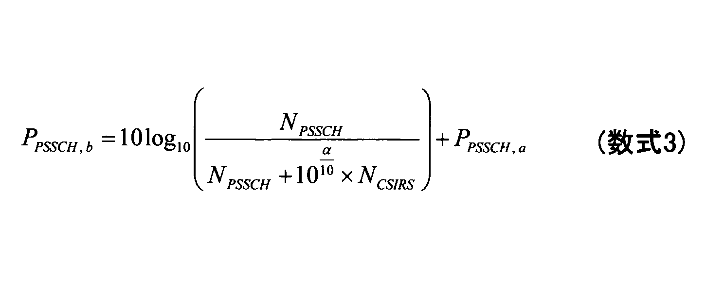
ここで、αは、仕様書に定義されている値(例えば、固定値又は変数)であってもよく、(事前に)設定されるパラメータであってもよく、指定されるパラメータであってもよい。PPSSCH,aは、PSCCH及びCSI-RSを伴わないPSCCHシンボルの送信電力であってもよく、或いはPSCCH及び/又はPSSCHの各シンボルの送信電力であってもよい。NCSIRSは、CSI-RSのリソース量に基づく値であってもよく、例えば、Physical Resource Block(PRB)の中のシンボルに含まれるCSI-RSのリソースエレメント(RE)の数であってもよい。NPSSCHは、PSSCHのリソース量に基づく値であってもよく、例えば、PRBの中のシンボルに含まれるPSSCHのREの数であってもよい。
Here, α may be a value defined in the specification (for example, a fixed value or a variable), a parameter set (in advance), or a specified parameter. Good. P PSSCH, a may be the transmission power of the PSCCH symbol without PSCCH and CSI-RS, or may be the transmission power of each symbol of PSCCH and / or PSCH. N CSIRS may be a value based on the amount of CSI-RS resources, and may be, for example, the number of CSI-RS resource elements (REs) included in the symbols in the Physical Resource Block (PRB). .. N PSSCH may be a value based on the amount of resources of PSSCH, and may be, for example, the number of REs of PSSCH included in the symbols in PRB.
図12に示される1スロットの区間において、各シンボルに割り当てられる合計の送信電力は、一定の値に維持されてもよい。この場合、端末20は、周波数領域でCSI-RSとPSCCHが多重されるシンボルについては、CSI-RSに割り当てられる送信電力をブーストして、かつ当該CSI-RS以外のPSCCHのリソースエレメントに割り当てられる電力を下げるといった動作を行うことが想定される。このように、CSI-RS及び/又はPT-RSの送信電力をブーストすることにより、チャネル状態情報の測定の精度を向上させることが可能となる。
The total transmission power assigned to each symbol in the one-slot section shown in FIG. 12 may be maintained at a constant value. In this case, the terminal 20 boosts the transmission power allocated to the CSI-RS and allocates it to the resource element of the PSCCH other than the CSI-RS for the symbol in which the CSI-RS and the PSCCH are multiplexed in the frequency domain. It is expected that operations such as lowering the power will be performed. By boosting the transmission power of CSI-RS and / or PT-RS in this way, it is possible to improve the accuracy of measuring the channel state information.
なお、上述の例では、CSI-RSに電力が割り当てられているので、当該CSI-RSの種別は、NZP-CSI-RS(Non-Zero-Power CSI-RS)であってもよい。
In the above example, since the power is assigned to the CSI-RS, the type of the CSI-RS may be NZP-CSI-RS (Non-Zero-Power CSI-RS).
図12に示される1スロットの区間において、各シンボルに割り当てられる合計の送信電力を一定の値に維持する理由として、仮に、1スロットの区間の途中で電力を変えると、RF装置が電力を変更するのに時間を要し、RF装置の送信の特性上の問題が発生することが考えられる。このような問題を回避するために、1つのスロットにおいて、シンボル間の送信電力を一定にしている。例えば、図12において、PSCCHとPSSCHが多重されている部分において、1シンボルに割り当てられる合計の送信電力がPであるとした場合、図12のスロットのCSI-RSとPSSCHが多重されている部分において、1シンボルに割り当てられる合計の送信電力はPとなる。1シンボルに割り当てられる合計の送信電力は一定であるため、複数のチャネルが周波数領域で多重される場合には、合計の送信電力を当該複数のチャネルに対して割り振ることになる。周波数領域で多重される複数のチャネルの中で、特定のチャネルを優先させたい場合には、当該特定のチャネルの送信電力をその他のチャネルの送信電力よりもブーストするといった方法を適用することが可能である。
As a reason for maintaining the total transmission power assigned to each symbol at a constant value in the section of 1 slot shown in FIG. 12, if the power is changed in the middle of the section of 1 slot, the RF device changes the power. It takes time to do so, and it is conceivable that problems with the transmission characteristics of the RF device may occur. In order to avoid such a problem, the transmission power between symbols is kept constant in one slot. For example, in FIG. 12, in the portion where PSCCH and PSCH are multiplexed, assuming that the total transmission power assigned to one symbol is P, the portion where CSI-RS and PSCH are multiplexed in the slot of FIG. In, the total transmission power assigned to one symbol is P. Since the total transmission power allocated to one symbol is constant, when a plurality of channels are multiplexed in the frequency domain, the total transmission power is allocated to the plurality of channels. If you want to prioritize a specific channel among multiple channels multiplexed in the frequency domain, you can apply a method such as boosting the transmission power of that specific channel over the transmission power of other channels. Is.
上述のCSI-RSは、少なくとも時間領域において、PSCCHと重なる(Overlap)ことが禁止されてもよい。同様に、上述のCSI-RSは、少なくとも時間領域において、PSSCHに関連付けられるDM-RSと重なる(Overlap)ことが禁止されてもよい。これにより、電力制御に関する数式の複雑化を回避することができ、すなわち端末の構成を簡易にすることが可能となる。
The above-mentioned CSI-RS may be prohibited from overlapping with PSCCH (Overlap) at least in the time domain. Similarly, the CSI-RS described above may be prohibited from overlapping with the DM-RS associated with the PSSCH, at least in the time domain. As a result, it is possible to avoid complication of mathematical formulas related to power control, that is, it is possible to simplify the configuration of the terminal.
あるいは、上述のCSI-RSは、少なくとも時間領域において、PSCCHと重なる(Overlap)ことが許容されてもよい。同様に、上述のCSI-RSは、少なくとも時間領域において、PSSCHに関連付けられるDM-RSと重なる(Overlap)ことが許容されてもよい。この場合、1つのシンボルにおいて、CSI-RSの送信電力は、PSSCH、PSCCH、PSSCH及び/又はPSCCHに関連付けられるDM-RSのうちの少なくとも一つの送信電力との比によって求められてもよい。上述の数式を後述する数式のように変更することで、優先させるべき信号をブーストすることが可能となる。なお、上述の例において、CSI-RSはPT-RSに置き換えられてもよい。
Alternatively, the CSI-RS described above may be allowed to overlap the PSCCH (Overlap), at least in the time domain. Similarly, the CSI-RS described above may be allowed to overlap (Overlap) with the DM-RS associated with the PSSCH, at least in the time domain. In this case, in one symbol, the transmit power of the CSI-RS may be determined by the ratio to the transmit power of at least one of the PSCH, PSCCH, PSCH and / or DM-RS associated with the PSCCH. By changing the above formula as the formula described later, it is possible to boost the signal to be prioritized. In the above example, CSI-RS may be replaced with PT-RS.
また、別の例として、1つのシンボルにおいて、周波数領域でPSSCH、CSI-RS、及びPT-RSを多重する場合、例えば、CSI-RSの送信電力PCSIRS、PT-RSの送信電力PPTRS、PSSCHに割り当てられる送信電力PPSSCH,cを以下のように規定してもよい。
Further, as another example, when PSSCH, CSI-RS, and PT-RS are multiplexed in the frequency domain in one symbol, for example, the transmission power P CSIRS of CSI-RS, the transmission power P PTRS of PT-RS, The transmission powers P PSSCH, c assigned to the PSSCH may be specified as follows.
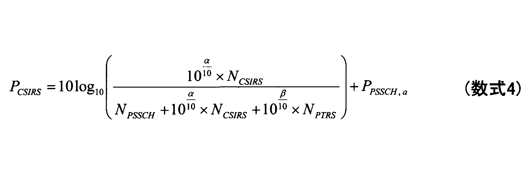
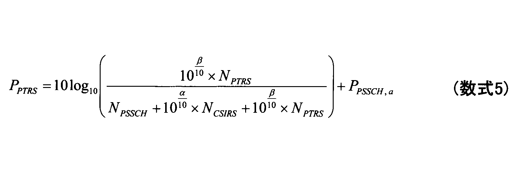
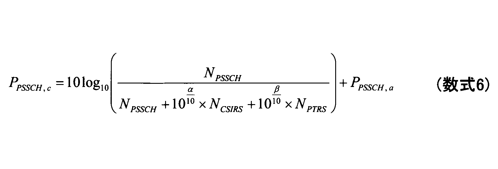
ここで、αは、仕様書により定義されている値(例えば、固定値又は変数)であってもよく、(事前に)設定されるパラメータであってもよく、指定されるパラメータであってもよい。βは、仕様により規定されるパラメータであってもよく、(事前に)設定されるパラメータであってもよく、指定されるパラメータであってもよい。PPSSCH,aは、PSCCH、CSI-RS及びPT-RSを伴わないPSSCHシンボルの送信電力であってもよく、或いはPSCCH及び/又はPSSCHの各シンボルの送信電力であってもよい。PPSSCH,cは、CSI-RS及びPT-RSを伴うPSSCHシンボルの送信電力であってもよい。NCSIRSは、CSI-RSのリソース量に基づく値であってもよく、例えば、Physical Resource Block(PRB)の中のシンボルに含まれるCSI-RSのリソースエレメント(RE)の数であってもよい。NPTRSは、PT-RSのリソース量に基づく値であってもよく、例えば、Physical Resource Block(PRB)の中のシンボルに含まれるPT-RSのリソースエレメント(RE)の数であってもよい。NPSSCHは、PSSCHのリソース量に基づく値であってもよく、例えば、PRBの中のシンボルに含まれるPSSCHのREの数であってもよい。
Here, α may be a value defined by the specification (for example, a fixed value or a variable), a parameter set (in advance), or a specified parameter. Good. β may be a parameter specified by the specification, a parameter set (in advance), or a specified parameter. P PSSCH, a may be the transmission power of the PSCCH symbol without PSCCH, CSI-RS and PT-RS, or may be the transmission power of each symbol of PSCCH and / or PSCH. P PSSCH, c may be the transmission power of the PSSCH symbol with CSI-RS and PT-RS. N CSIRS may be a value based on the amount of CSI-RS resources, and may be, for example, the number of CSI-RS resource elements (REs) included in the symbols in the Physical Resource Block (PRB). .. N PTRS may be a value based on the amount of PT-RS resources, and may be, for example, the number of PT-RS resource elements (REs) included in the symbols in the Physical Resource Block (PRB). .. N PSSCH may be a value based on the amount of resources of PSSCH, and may be, for example, the number of REs of PSSCH included in the symbols in PRB.
また、別の例として、1つのシンボルにおいて、周波数領域でPSCCH、PSSCH及びCSI-RSを多重する場合、例えば、CSI-RSの送信電力PCSIRS、PSCCHの送信電力PPSCCH、PSSCHに割り当てられる送信電力PPSSCH,cを以下のように規定してもよい。
The transmission, as another example, in one symbol, when multiplexing PSCCH, the PSSCH and CSIRS in the frequency domain, for example, the transmission power P CSIRS of CSIRS, transmission power P PSCCH of PSCCH, assigned to PSSCH The power P PSSCH, c may be specified as follows.

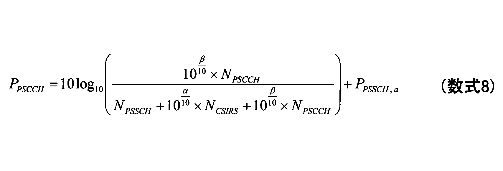
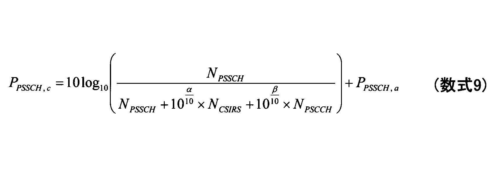
ここで、αは、仕様により規定されるパラメータであってもよく、(事前に)設定されるパラメータであってもよく、指定されるパラメータであってもよい。βは、仕様により規定されるパラメータであってもよく、(事前に)設定されるパラメータであってもよく、指定されるパラメータであってもよい。PPSSCH,aは、PSCCH、CSI-RS及びPT-RSを伴わないPSSCHシンボルの送信電力であってもよく、或いはPSCCH及び/又はPSSCHの各シンボルの送信電力であってもよい。PPSSCH,cは、CSI-RS及びPT-RSを伴うPSSCHシンボルの送信電力であってもよい。NCSIRSは、CSI-RSのリソース量に基づく値であってもよく、例えば、PRBの中のシンボルに含まれるCSI-RSのREの数であってもよい。NPSCCHは、PSCCHのリソース量に基づく値であってもよく、例えば、PRBの中のシンボルに含まれるPSSCHのREの数であってもよい。NPSSCHは、PSSCHのリソース量に基づく値であってもよく、例えば、PRBの中のシンボルに含まれるPSSCHのREの数であってもよい。
Here, α may be a parameter specified by the specification, a parameter set (in advance), or a specified parameter. β may be a parameter specified by the specification, a parameter set (in advance), or a specified parameter. P PSSCH, a may be the transmission power of the PSCCH symbol without PSCCH, CSI-RS and PT-RS, or may be the transmission power of each symbol of PSCCH and / or PSCH. P PSSCH, c may be the transmission power of the PSSCH symbol with CSI-RS and PT-RS. N CSIRS may be a value based on the resource amount of CSI-RS, and may be, for example, the number of REs of CSI-RS included in the symbol in PRB. N PSCCH may be a value based on the amount of resources of PSCCH, and may be, for example, the number of REs of PSCH included in the symbol in PRB. N PSSCH may be a value based on the amount of resources of PSSCH, and may be, for example, the number of REs of PSSCH included in the symbols in PRB.
ここで、ZP-CSI-RS(Zero-Power CSI-RS)の場合、NCSIRS=0としてもよい。
Here, in the case of ZP-CSI-RS (Zero-Power CSI-RS), N CSIRS = 0 may be set.
(A1-2)
端末20が、CSI-RS及び/又はPT-RSの送信電力をブーストするか否か、及びCSI-RSの送信電力の増加量及び/又はPT-RSの送信電力の増加量(例えば、A1-1における数式内のαの値及び/又はβの値)は、仕様書により規定されてもよい。例えば、α=3、β=3であってもよい。端末20が、CSI-RS及び/又はPT-RSの送信電力をブーストするか否か、及びCSI-RSの送信電力の増加量及び/又はPT-RSの送信電力の増加量(例えば、A1-1における数式内のαの値及び/又はβの値)は、例えば、ネットワークにより(事前に)設定されてもよく、サイドリンクでのRRCシグナリングである他の端末20により送信されるPC5-RRCメッセージにより設定されてもよい。また、端末20が、CSI-RS及び/又はPT-RSの送信電力をブーストするか否か、及びCSI-RSの送信電力の増加量及び/又はPT-RSの送信電力の増加量(例えば、A1-1における数式内のαの値及び/又はβの値)は、例えば、スケジューリングを行うための、Downlink Control Information(DCI)及び/又はSidelink Control Information(SCI)により指定されてもよい。例えば、DCI/SCIにおいて、送信電力制御のための専用のフィールドが規定されてもよい。また、CSI-RSの存在/設定を示す他のフィールドが規定されてもよい。また、端末20が、CSI-RS及び/又はPT-RSの送信電力をブーストするか否か、及びCSI-RSの送信電力の増加量及び/又はPT-RSの送信電力の増加量(例えば、A1-1における数式内のαの値及び/又はβの値)は、例えば、CSI-RSの構成及び/又はPT-RSの構成に依存してもよく、追加的に又は代替的に、CSI-RSのリソース及び/又はPT-RSのリソースに依存してもよい。例えば、CSI-RS及び/又はPT-RSのリソースが少ない場合には、CSI-RS及び/又はPT-RSの送信電力をブーストし、CSI-RS及び/又はPT-RSのリソースが多い場合には、CSI-RS及び/又はPT-RSの送信電力は、PSSCHに割り当てられる送信電力と同じ値に設定されてもよい。また、CSI-RS及び/又はPT-RSの構成の中に送信電力をブーストするか否かを示す要素を含めてもよい。なお、これらの情報は、上位レイヤのパラメータ等に基づいて決定されてもよく、上位レイヤのパラメータとDCI及び/又はSCIとの組み合わせに基づいて決定されてもよい。 (A1-2)
Whether or not the terminal 20 boosts the transmission power of the CSI-RS and / or the PT-RS, and the amount of increase in the transmission power of the CSI-RS and / or the amount of increase in the transmission power of the PT-RS (for example, A1- The value of α and / or the value of β in the mathematical formula in 1) may be specified by the specifications. For example, α = 3 and β = 3 may be set. Whether or not the terminal 20 boosts the transmission power of CSI-RS and / or PT-RS, and the amount of increase in the transmission power of CSI-RS and / or the amount of increase in the transmission power of PT-RS (for example, A1- The value of α and / or the value of β in the formula in 1) may be set (in advance) by the network, for example, and is transmitted by another terminal 20 which is RRC signaling on the side link PC5-RRC. It may be set by a message. Further, whether or not the terminal 20 boosts the transmission power of CSI-RS and / or PT-RS, and the amount of increase in the transmission power of CSI-RS and / or the amount of increase in the transmission power of PT-RS (for example, The value of α and / or the value of β in the mathematical formula in A1-1) may be specified by, for example, the Downlink Control Information (DCI) and / or the Sidelink Control Information (SCI) for scheduling. For example, in DCI / SCI, a dedicated field for transmission power control may be specified. In addition, other fields indicating the existence / setting of CSI-RS may be specified. Further, whether or not the terminal 20 boosts the transmission power of CSI-RS and / or PT-RS, and the amount of increase in the transmission power of CSI-RS and / or the amount of increase in the transmission power of PT-RS (for example, The value of α and / or the value of β in the formula in A1-1) may depend on, for example, the configuration of CSI-RS and / or the configuration of PT-RS, and additionally or alternately, CSI. -It may depend on RS resources and / or PT-RS resources. For example, when the resources of CSI-RS and / or PT-RS are low, the transmission power of CSI-RS and / or PT-RS is boosted, and when the resources of CSI-RS and / or PT-RS are high. The transmission power of CSI-RS and / or PT-RS may be set to the same value as the transmission power assigned to the PSSCH. Further, an element indicating whether or not to boost the transmission power may be included in the configuration of CSI-RS and / or PT-RS. It should be noted that these pieces of information may be determined based on the parameters of the upper layer and the like, or may be determined based on the combination of the parameters of the upper layer and DCI and / or SCI.
(A1-3)
CSI-RSの送信電力を算出するための関数は、端末20の最大送信電力以外については、PSSCHに割り当てられる送信電力の値を考慮しない関数であってもよい。同様に、PT-RSの送信電力を算出するための関数は、端末20の最大送信電力以外については、PSSCHに割り当てられる送信電力の値を考慮しない関数であってもよい。この場合、CSI-RSの送信電力は、PSSCHに割り当てられる送信電力の値に対する比を用いて算出されるものではなくなる。同様に、PT-RSの送信電力は、PSSCHに割り当てられる送信電力の値に対する比を用いて算出されるものではなくなる。このように、オプションA1を適用することによって、CSI-RS及び/又はPT-RSをブーストすることにより、チャネル状態情報を取得する際の精度を向上させることが可能となり、RSRP測定の精度を向上させることが可能となり、かつ/又は位相雑音を補償する際の精度を向上させることが可能となる。 (A1-3)
The function for calculating the transmission power of the CSI-RS may be a function that does not consider the value of the transmission power assigned to the PSCH except for the maximum transmission power of the terminal 20. Similarly, the function for calculating the transmission power of the PT-RS may be a function that does not consider the value of the transmission power assigned to the PSCH except for the maximum transmission power of the terminal 20. In this case, the transmission power of CSI-RS is not calculated by using the ratio to the value of the transmission power assigned to PSCH. Similarly, the transmission power of the PT-RS is no longer calculated using the ratio to the value of the transmission power assigned to the PSCH. In this way, by applying option A1, by boosting CSI-RS and / or PT-RS, it is possible to improve the accuracy when acquiring channel state information, and the accuracy of RSRP measurement is improved. And / or the accuracy at the time of compensating for the phase noise can be improved.
(オプションA2)
端末20は、PSSCHと関連付けられたCSI-RS及び/又はPT-RSの送信電力を、PSSCHの送信電力と必ず同じに設定してもよい。すなわち、PSSCHの合計の送信電力PPSSCHは、CSI-RSの送信電力及び/又はPT-RSの送信電力を含み、かつPSSCHデータのRE、CSI-RSのRE、及び/又はPT-RSのREの間で均等に分配されてもよい。この構成によれば、装置の実装が容易になり、かつ仕様の変更も少なくすることが可能となる。 (Option A2)
The terminal 20 may set the transmission power of the CSI-RS and / or the PT-RS associated with the PSCH to be always the same as the transmission power of the PSCH. That is, the total transmission power P PSSCH of the PSSCH includes the transmission power of the CSI-RS and / or the transmission power of the PT-RS, and the RE of the PSCH data, the RE of the CSI-RS, and / or the RE of the PT-RS. It may be evenly distributed among them. According to this configuration, it is possible to easily mount the device and reduce changes in specifications.
なお、端末20は、送信電力を、送信機会i毎に算出してもよく、リソースプール毎に算出してもよく、サブチャネル毎に算出してもよく、或いは、ユニキャスト、グループキャスト、及びブロードキャスト等のキャスト種別毎に算出してもよい。例えば、送信電力は、送信機会iの送信期間の長さ、リソースプールの大きさ、サブチャネル、キャスト種別に基づいて、決定されてもよい。なお、送信電力は、送信機会iの送信期間の長さ、リソースプールの大きさ、サブチャネル、キャスト種別に依存せずに、上記の計算式に基づいて決定されてもよい。また、上述の実施例において、CSI-RS及び/又はPT-RSを、DM-RSに置き換えてもよい。また、上述の実施例において、「送信電力」は「RE毎の送信電力」に置き換えられてもよい。
The terminal 20 may calculate the transmission power for each transmission opportunity i, for each resource pool, for each subchannel, or for unicast, groupcast, and so on. It may be calculated for each cast type such as broadcast. For example, the transmission power may be determined based on the length of the transmission period of the transmission opportunity i, the size of the resource pool, the subchannel, and the cast type. The transmission power may be determined based on the above formula without depending on the length of the transmission period of the transmission opportunity i, the size of the resource pool, the subchannel, and the cast type. Further, in the above-described embodiment, CSI-RS and / or PT-RS may be replaced with DM-RS. Further, in the above-described embodiment, "transmission power" may be replaced with "transmission power for each RE".
(課題B)
NRのサイドリンクのグループキャスト通信に対して、サイドリンクのパスロスに基づいて開ループ送信電力制御を行ってもよい。 (Problem B)
For NR side-link group cast communication, open-loop transmission power control may be performed based on the side-link path loss.
NRのサイドリンクのグループキャスト通信に対して、サイドリンクのパスロスに基づいて開ループ送信電力制御を行ってもよい。 (Problem B)
For NR side-link group cast communication, open-loop transmission power control may be performed based on the side-link path loss.
図13は、NRのサイドリンクのグループキャスト通信に対して、サイドリンクのパスロスに基づく開ループ送信電力制御を行う場合の例を示す図である。図13に示されるように、サイドリンクに基づく開ループ送信電力制御を適用することで、例えば、送信側の端末20から最も距離が離れている受信側の端末20、すなわち、グループ内で、サイドリンクのパスロスの値が最大となる受信側の端末20が、送信側の端末20からの無線信号を受信できるように送信電力を制御することが可能となる。また、グループ内で、サイドリンクのパスロスの値が最大となる受信側の端末20が、送信側の端末20からの無線信号を受信するために必要かつ十分な送信電力の値よりも大きい値に送信電力を設定することは行わないため、他のグループに対する干渉を低減することが可能となる。しかしながら、図13に示されるように、グループ内の端末20の数が増えると、それに伴って、より多くの測定のリソース及びより多くのフィードバックのリソースが必要となる。
FIG. 13 is a diagram showing an example in which open-loop transmission power control based on the path loss of the side link is performed for the group cast communication of the side link of NR. As shown in FIG. 13, by applying the open-loop transmission power control based on the side link, for example, the receiving terminal 20 farthest from the transmitting terminal 20, that is, the side in the group. It is possible to control the transmission power so that the receiving-side terminal 20 having the maximum link path loss value can receive the radio signal from the transmitting-side terminal 20. Further, in the group, the receiving side terminal 20 having the maximum side link path loss value becomes a value larger than the value of the transmitting power necessary and sufficient to receive the radio signal from the transmitting side terminal 20. Since the transmission power is not set, it is possible to reduce interference with other groups. However, as the number of terminals 20 in the group increases, as shown in FIG. 13, more measurement resources and more feedback resources are required accordingly.
(提案B)
NRのサイドリンクのグループキャスト通信に対して、サイドリンクのパスロスに基づく開ループ送信電力制御を適用するか否かを選択するための条件が規定されてもよい。 (Proposal B)
Conditions may be specified for selecting whether or not to apply open-loop transmission power control based on the path loss of the side link to the group cast communication of the side link of the NR.
NRのサイドリンクのグループキャスト通信に対して、サイドリンクのパスロスに基づく開ループ送信電力制御を適用するか否かを選択するための条件が規定されてもよい。 (Proposal B)
Conditions may be specified for selecting whether or not to apply open-loop transmission power control based on the path loss of the side link to the group cast communication of the side link of the NR.
(オプションB1)
NRのサイドリンクのグループキャスト通信において、グループ内の受信側の端末20全てのRSRPが送信側の端末20で使用可能な場合に、送信側の端末20は、サイドリンクのパスロスに基づく開ループ送信電力制御を適用してもよい。グループ内の受信側の端末20のうち、少なくとも1つの受信側の端末20のRSRPが送信側の端末20で使用できない場合には、送信側の端末20は、サイドリンクのパスロスに基づく開ループ送信電力制御を無効としてもよい。この場合、下りリンクのパスロスに基づく開ループ送信電力制御が適用されてもよい。 (Option B1)
In NR side-link group cast communication, when all RSRPs of the receivingterminal 20 in the group can be used by the transmitting terminal 20, the transmitting terminal 20 transmits an open loop based on the path loss of the side link. Power control may be applied. If the RSRP of at least one receiving side terminal 20 among the receiving side terminals 20 in the group cannot be used by the transmitting side terminal 20, the transmitting side terminal 20 transmits an open loop based on the path loss of the side link. Power control may be disabled. In this case, open-loop transmission power control based on the downlink path loss may be applied.
NRのサイドリンクのグループキャスト通信において、グループ内の受信側の端末20全てのRSRPが送信側の端末20で使用可能な場合に、送信側の端末20は、サイドリンクのパスロスに基づく開ループ送信電力制御を適用してもよい。グループ内の受信側の端末20のうち、少なくとも1つの受信側の端末20のRSRPが送信側の端末20で使用できない場合には、送信側の端末20は、サイドリンクのパスロスに基づく開ループ送信電力制御を無効としてもよい。この場合、下りリンクのパスロスに基づく開ループ送信電力制御が適用されてもよい。 (Option B1)
In NR side-link group cast communication, when all RSRPs of the receiving
なお、受信側の端末20のRSRPは、送信側の端末20が受信側の端末20からフィードバックされるRSRPを受信することにより使用可能とされてもよく、或いは送信側の端末20が受信側の端末20から送信されるRSを受信して送信側の端末20がRSRPを測定することにより使用可能とされてもよい。
The RSRP of the receiving terminal 20 may be enabled by the transmitting terminal 20 receiving the RSRP fed back from the receiving terminal 20, or the transmitting terminal 20 may be on the receiving side. It may be enabled by receiving the RS transmitted from the terminal 20 and having the transmitting terminal 20 measure the RSRP.
このように、少なくとも1つの受信側の端末20のRSRPが送信側の端末20で使用できない場合、少なくとも1つの受信側の端末20はグループキャスト通信の信号を受信することができない可能性がある。この場合において、サイドリンクのパスロスに基づく開ループ送信電力制御は効果的ではない。オプションB1の手法によれば、サイドリンクのパスロスに基づく開ループ送信電力制御が効果的な場合にのみ、当該送信電力制御を適用することが可能となる。
As described above, when the RSRP of at least one receiving side terminal 20 cannot be used by the transmitting side terminal 20, at least one receiving side terminal 20 may not be able to receive the signal of the group cast communication. In this case, open-loop transmission power control based on the side link path loss is not effective. According to the method of option B1, the transmission power control can be applied only when the open-loop transmission power control based on the side link path loss is effective.
(オプションB2)
NRのサイドリンクのグループキャスト通信において、グループキャストのAcknowlegement(ACK)/Negative-Acknowledgement(NACK)フィードバックが有効とされている場合に、送信側の端末20は、サイドリンクのパスロスに基づく開ループ送信電力制御を適用してもよい。グループキャストのACK/NACKフィードバックが無効とされている場合には、送信側の端末20は、サイドリンクのパスロスに基づく開ループ送信電力制御を適用しなくてもよい。 (Option B2)
In the NR side-link group cast communication, when the group cast Acknowledgement (ACK) / Negative-Acknowledgement (NACK) feedback is enabled, the transmittingterminal 20 transmits an open loop based on the side link path loss. Power control may be applied. When the group cast ACK / NACK feedback is disabled, the transmitting terminal 20 does not have to apply open-loop transmission power control based on the side link path loss.
NRのサイドリンクのグループキャスト通信において、グループキャストのAcknowlegement(ACK)/Negative-Acknowledgement(NACK)フィードバックが有効とされている場合に、送信側の端末20は、サイドリンクのパスロスに基づく開ループ送信電力制御を適用してもよい。グループキャストのACK/NACKフィードバックが無効とされている場合には、送信側の端末20は、サイドリンクのパスロスに基づく開ループ送信電力制御を適用しなくてもよい。 (Option B2)
In the NR side-link group cast communication, when the group cast Acknowledgement (ACK) / Negative-Acknowledgement (NACK) feedback is enabled, the transmitting
ここで、グループキャストのAcknowlegement(ACK)/Negative-Acknowledgement(NACK)フィードバックは、トランスポートブロックの復号に成功した場合に、受信側の端末20はACKを送信し、トランスポートブロックの復号に失敗した場合に、受信側の端末20はNACKを送信することを意味してもよい。すなわち、グループキャストのACK/NACKフィードバックが有効とされることは、通信に対するより高い信頼性が要求されること、及び/又はグループ内の端末20の数が少ないことを意味する。従って、グループキャストのACK/NACKフィードバックが有効とされる場合には、サイドリンクのパスロスに基づく開ループ送信電力制御を適用することで、より通信の信頼性を高めることが望ましいと想定される。グループキャストのACK/NACKフィードバックが無効とされる場合には、サイドリンクのパスロスに基づく開ループ送信電力制御を適用することは必要ではない可能性がある。
Here, in the group cast Acknowledgement (ACK) / Meaning-Acknowledgement (NACK) feedback, when the transport block is successfully decoded, the receiving terminal 20 transmits ACK and the transport block decoding fails. In this case, the receiving terminal 20 may mean transmitting NACK. That is, the fact that the ACK / NACK feedback of the group cast is valid means that higher reliability for communication is required and / or the number of terminals 20 in the group is small. Therefore, when the ACK / NACK feedback of the group cast is valid, it is assumed that it is desirable to further improve the reliability of communication by applying the open-loop transmission power control based on the path loss of the side link. If group cast ACK / NACK feedback is disabled, it may not be necessary to apply open-loop transmit power control based on sidelink path loss.
なお、オプションB2において、「グループキャストのAcknowlegement(ACK)/Negative-Acknowledgement(NACK)フィードバック」は、「グループキャストのHARQ-ACKフィードバック」に置き換えられてもよい。グループキャストのHARQ-ACKフィードバックには、以下の二つの手法のうち少なくとも一つが含まれていてもよい。
1.トランスポートブロックの復号に成功した場合に、受信側の端末20はACKを送信し、トランスポートブロックの復号に失敗した場合に、受信側の端末20はNACKを送信する。
2.トランスポートブロックの復号に成功した場合には、受信側の端末20はACK及びNACKを送信せず、トランスポートブロックの復号に失敗した場合に、受信側の端末20はNACKを送信する。 In option B2, "group cast Acknowledgement (ACK) / Negative-Acknowledgement (NACK) feedback" may be replaced with "group cast HARQ-ACK feedback". The HARQ-ACK feedback of the group cast may include at least one of the following two methods.
1. 1. When the transport block is successfully decoded, the receivingterminal 20 transmits an ACK, and when the transport block decoding fails, the receiving terminal 20 transmits an NACK.
2. 2. If the decoding of the transport block is successful, the receivingterminal 20 does not transmit ACK and NACK, and if the decoding of the transport block fails, the receiving terminal 20 transmits NACK.
1.トランスポートブロックの復号に成功した場合に、受信側の端末20はACKを送信し、トランスポートブロックの復号に失敗した場合に、受信側の端末20はNACKを送信する。
2.トランスポートブロックの復号に成功した場合には、受信側の端末20はACK及びNACKを送信せず、トランスポートブロックの復号に失敗した場合に、受信側の端末20はNACKを送信する。 In option B2, "group cast Acknowledgement (ACK) / Negative-Acknowledgement (NACK) feedback" may be replaced with "group cast HARQ-ACK feedback". The HARQ-ACK feedback of the group cast may include at least one of the following two methods.
1. 1. When the transport block is successfully decoded, the receiving
2. 2. If the decoding of the transport block is successful, the receiving
(オプションB3)
NRのサイドリンクのグループキャスト通信において、グループ内の端末20の数に応じて、送信側の端末20装置は、サイドリンクのパスロスに基づく開ループ送信電力制御を適用するか否かを決定してもよい。例えば、グループ内の端末20の数が、閾値Xよりも小さい(又はX以下の)場合には、送信側の端末20装置は、サイドリンクのパスロスに基づく開ループ送信電力制御を適用してもよい。グループ内の端末20の数が閾値X以上である(又はXよりも大きい)場合には、送信側の端末20装置は、サイドリンクのパスロスに基づく開ループ送信電力制御を適用しなくてもよい。ここで、閾値Xは、仕様により規定されてもよく、ネットワークにより(事前に)設定されてもよく、サイドリンクでのRRCシグナリングである他の端末20により送信されるPC5-RRCメッセージにより設定されてもよく、リソースプールの設定に基づいて規定又は決定されてもよく、かつ/又は輻輳レベルに基づいて規定されてもよい。 (Option B3)
In the group cast communication of the side link of NR, the terminal 20 device on the transmitting side determines whether or not to apply the open-loop transmission power control based on the path loss of the side link according to the number ofterminals 20 in the group. May be good. For example, if the number of terminals 20 in the group is less than (or less than or equal to) the threshold X, the transmitting terminal 20 device may apply open-loop transmission power control based on sidelink path loss. Good. If the number of terminals 20 in the group is greater than or equal to the threshold X (or greater than X), the transmitting terminal 20 device may not apply open-loop transmit power control based on sidelink path loss. .. Here, the threshold value X may be specified by specifications, may be set (in advance) by the network, and may be set by a PC5-RRC message transmitted by another terminal 20 which is RRC signaling on the side link. It may be specified or determined based on the resource pool settings and / or may be specified based on the congestion level.
NRのサイドリンクのグループキャスト通信において、グループ内の端末20の数に応じて、送信側の端末20装置は、サイドリンクのパスロスに基づく開ループ送信電力制御を適用するか否かを決定してもよい。例えば、グループ内の端末20の数が、閾値Xよりも小さい(又はX以下の)場合には、送信側の端末20装置は、サイドリンクのパスロスに基づく開ループ送信電力制御を適用してもよい。グループ内の端末20の数が閾値X以上である(又はXよりも大きい)場合には、送信側の端末20装置は、サイドリンクのパスロスに基づく開ループ送信電力制御を適用しなくてもよい。ここで、閾値Xは、仕様により規定されてもよく、ネットワークにより(事前に)設定されてもよく、サイドリンクでのRRCシグナリングである他の端末20により送信されるPC5-RRCメッセージにより設定されてもよく、リソースプールの設定に基づいて規定又は決定されてもよく、かつ/又は輻輳レベルに基づいて規定されてもよい。 (Option B3)
In the group cast communication of the side link of NR, the terminal 20 device on the transmitting side determines whether or not to apply the open-loop transmission power control based on the path loss of the side link according to the number of
このように、グループ内の端末20の数が少ない場合には、測定のリソース及びフィードバックのリソースは少なくなる。この場合、サイドリンクのパスロスに基づく開ループ送信電力制御を適用することは効果的であると想定される。
In this way, when the number of terminals 20 in the group is small, the measurement resource and the feedback resource are small. In this case, it is assumed that it is effective to apply open-loop transmission power control based on the path loss of the side link.
(オプションB4)
3GPPの会合では、距離に関連する情報(例えば、距離及び/又はRSRP)に応じてHybrid Automatic Repeat Request(HARQ)フィードバックを行うか否かが定まる機能(distance-based HARQ)が検討されている。送信側の端末20に距離的に近い受信側の端末20は、HARQフィードバックを行う。送信側の端末20から距離的に遠い受信側の端末20に対しては、それ程高い信頼性が要求されないことが想定されるため、距離的に遠い受信側の端末20は、HARQフィードバックを行わなくてもよい。 (Option B4)
At the 3GPP meeting, a function (distance-based HARQ) that determines whether or not to provide Hybrid Automatic Repeat Request (HARQ) feedback according to distance-related information (for example, distance and / or RSRP) is being examined. The receivingside terminal 20 which is close to the transmitting side terminal 20 provides HARQ feedback. Since it is assumed that the receiving terminal 20 that is far from the transmitting terminal 20 is not required to have such high reliability, the receiving terminal 20 that is far away does not perform HARQ feedback. You may.
3GPPの会合では、距離に関連する情報(例えば、距離及び/又はRSRP)に応じてHybrid Automatic Repeat Request(HARQ)フィードバックを行うか否かが定まる機能(distance-based HARQ)が検討されている。送信側の端末20に距離的に近い受信側の端末20は、HARQフィードバックを行う。送信側の端末20から距離的に遠い受信側の端末20に対しては、それ程高い信頼性が要求されないことが想定されるため、距離的に遠い受信側の端末20は、HARQフィードバックを行わなくてもよい。 (Option B4)
At the 3GPP meeting, a function (distance-based HARQ) that determines whether or not to provide Hybrid Automatic Repeat Request (HARQ) feedback according to distance-related information (for example, distance and / or RSRP) is being examined. The receiving
NRのサイドリンクのグループキャスト通信において、HARQフィードバックを行う受信側の端末20のRSRPが送信側の端末20で使用可能な場合、送信側の端末20装置は、サイドリンクのパスロスに基づく開ループ送信電力制御を適用してもよい。HARQフィードバックを行う受信側の端末20のRSRPが送信側の端末20で使用可能ではない場合、送信側の端末20装置は、サイドリンクのパスロスに基づく開ループ送信電力制御を適用しなくてもよい。
In NR side-link group cast communication, when the RSRP of the receiving terminal 20 that performs HARQ feedback is available on the transmitting terminal 20, the transmitting terminal 20 device performs open-loop transmission based on the path loss of the side link. Power control may be applied. If the RSRP of the receiving terminal 20 performing HARQ feedback is not available on the transmitting terminal 20, the transmitting terminal 20 device may not apply open-loop transmit power control based on sidelink path loss. ..
図14は、distance-based HARQが適用される場合に、サイドリンクのパスロスに基づく開ループ送信電力制御を適用する例を示す図である。HARQフィードバックが有効とされている受信側の端末20に対しては、通信に対する高い信頼性が要求されることが想定される。従って、HARQフィードバックが有効とされている受信側の端末20のRSRPを取得した上で、サイドリンクのパスロスに基づく開ループ送信電力制御を適用することで、通信に対する信頼性を向上することが可能となる。なお、受信側の端末20のRSRPは、送信側の端末20が受信側の端末20からフィードバックされるRSRPを受信することにより使用可能とされてもよく、或いは送信側の端末20が受信側の端末20から送信されるRSを受信して送信側の端末20がRSRPを測定することにより使用可能とされてもよい。例えば、上述のdistance-based HARQにおいて、送信側の端末20と受信側の端末20との間の距離が閾値Y未満(又は以下)である場合に、受信側の端末20で、HARQフィードバックが有効とされてもよい。ここで、閾値Yは、仕様により規定されてもよく、ネットワークにより(事前に)設定されてもよく、サイドリンクでのRRCシグナリングである他の端末20により送信されるPC5-RRCメッセージにより設定されてもよく、リソースプールの設定に基づいて規定されてもよく、かつ/又は輻輳レベルに基づいて規定されてもよい。
FIG. 14 is a diagram showing an example in which open-loop transmission power control based on the path loss of the side link is applied when the distance-based HARQ is applied. It is assumed that the receiving terminal 20 for which HARQ feedback is valid is required to have high reliability for communication. Therefore, it is possible to improve the reliability of communication by acquiring the RSRP of the receiving terminal 20 for which HARQ feedback is valid and then applying the open-loop transmission power control based on the path loss of the side link. It becomes. The RSRP of the receiving terminal 20 may be enabled by the transmitting terminal 20 receiving the RSRP fed back from the receiving terminal 20, or the transmitting terminal 20 may be on the receiving side. It may be enabled by receiving the RS transmitted from the terminal 20 and having the transmitting terminal 20 measure the RSRP. For example, in the above-mentioned distance-based HARQ, when the distance between the transmitting side terminal 20 and the receiving side terminal 20 is less than (or less than) the threshold value Y, the HARQ feedback is effective on the receiving side terminal 20. May be. Here, the threshold value Y may be specified by specifications, may be set (in advance) by the network, and may be set by a PC5-RRC message transmitted by another terminal 20 which is RRC signaling on the side link. It may be specified based on the resource pool settings and / or the congestion level.
このように、オプションB4の手法によれば、通信に対する高い信頼性が要求される受信側の端末20に対してのみ、サイドリンクのパスロスに基づく開ループ送信電力制御を適用することで、当該受信側の端末20との通信に対する信頼性を向上することが可能となる。
As described above, according to the method of option B4, the open-loop transmission power control based on the path loss of the side link is applied only to the receiving terminal 20 that requires high reliability for communication, thereby receiving the reception. It is possible to improve the reliability of communication with the terminal 20 on the side.
(オプションB5)
NRのサイドリンクのグループキャスト通信において、range requirementを満たす受信側の端末20全てのRSRPが送信側の端末20で使用可能である場合には、送信側の端末20は、サイドリンクのパスロスに基づく開ループ送信電力制御を適用してもよい。上記以外の場合には、送信側の端末20は、サイドリンクのパスロスに基づく開ループ送信電力制御を適用しなくてもよい。なお、受信側の端末20のRSRPは、送信側の端末20が受信側の端末20からフィードバックされるRSRPを受信することにより使用可能とされてもよく、或いは送信側の端末20が受信側の端末20から送信されるRSを受信して送信側の端末20がRSRPを測定することにより使用可能とされてもよい。 (Option B5)
In the group cast communication of the side link of NR, if all RSRPs of the receivingterminal 20 satisfying the change requirement are available in the transmitting terminal 20, the transmitting terminal 20 is based on the path loss of the side link. Open-loop transmit power control may be applied. In cases other than the above, the transmitting terminal 20 does not have to apply the open-loop transmission power control based on the path loss of the side link. The RSRP of the receiving terminal 20 may be enabled by the transmitting terminal 20 receiving the RSRP fed back from the receiving terminal 20, or the transmitting terminal 20 may be on the receiving side. It may be enabled by receiving the RS transmitted from the terminal 20 and having the transmitting terminal 20 measure the RSRP.
NRのサイドリンクのグループキャスト通信において、range requirementを満たす受信側の端末20全てのRSRPが送信側の端末20で使用可能である場合には、送信側の端末20は、サイドリンクのパスロスに基づく開ループ送信電力制御を適用してもよい。上記以外の場合には、送信側の端末20は、サイドリンクのパスロスに基づく開ループ送信電力制御を適用しなくてもよい。なお、受信側の端末20のRSRPは、送信側の端末20が受信側の端末20からフィードバックされるRSRPを受信することにより使用可能とされてもよく、或いは送信側の端末20が受信側の端末20から送信されるRSを受信して送信側の端末20がRSRPを測定することにより使用可能とされてもよい。 (Option B5)
In the group cast communication of the side link of NR, if all RSRPs of the receiving
このように、オプションB5の手法によれば、グループキャスト送信を受信することが期待される端末20に対してのみ、サイドリンクのパスロスに基づく開ループ送信電力制御を適用することで、当該端末20との通信に対する信頼性を向上することが可能となる。
As described above, according to the method of option B5, the open-loop transmission power control based on the path loss of the side link is applied only to the terminal 20 which is expected to receive the group cast transmission. It is possible to improve the reliability of communication with.
(オプションB6)
上述のオプションB1からオプションB5のうち、少なくとも2つのオプションを組み合わせてもよい。例えば、オプションB1及びオプションB2の条件を満たす場合、送信側の端末20装置は、サイドリンクのパスロスに基づく開ループ送信電力制御を適用してもよい。それ以外の場合には、送信側の端末20装置は、サイドリンクのパスロスに基づく開ループ送信電力制御を適用しなくてもよい。代替的に、例えば、オプションB1又はオプションB2の条件を満たす場合、送信側の端末20装置は、サイドリンクのパスロスに基づく開ループ送信電力制御を適用してもよい。それ以外の場合には、送信側の端末20装置は、サイドリンクのパスロスに基づく開ループ送信電力制御を適用しなくてもよい。 (Option B6)
At least two of the above options B1 to B5 may be combined. For example, if the conditions of option B1 and option B2 are satisfied, the terminal 20 device on the transmitting side may apply open-loop transmission power control based on the path loss of the side link. In other cases, the transmittingterminal 20 device does not have to apply open-loop transmission power control based on the side link path loss. Alternatively, for example, if the conditions of option B1 or option B2 are satisfied, the transmitting terminal 20 device may apply open-loop transmission power control based on the path loss of the side link. In other cases, the transmitting terminal 20 device does not have to apply open-loop transmission power control based on the side link path loss.
上述のオプションB1からオプションB5のうち、少なくとも2つのオプションを組み合わせてもよい。例えば、オプションB1及びオプションB2の条件を満たす場合、送信側の端末20装置は、サイドリンクのパスロスに基づく開ループ送信電力制御を適用してもよい。それ以外の場合には、送信側の端末20装置は、サイドリンクのパスロスに基づく開ループ送信電力制御を適用しなくてもよい。代替的に、例えば、オプションB1又はオプションB2の条件を満たす場合、送信側の端末20装置は、サイドリンクのパスロスに基づく開ループ送信電力制御を適用してもよい。それ以外の場合には、送信側の端末20装置は、サイドリンクのパスロスに基づく開ループ送信電力制御を適用しなくてもよい。 (Option B6)
At least two of the above options B1 to B5 may be combined. For example, if the conditions of option B1 and option B2 are satisfied, the terminal 20 device on the transmitting side may apply open-loop transmission power control based on the path loss of the side link. In other cases, the transmitting
上述のオプションB1からオプションB6までのいずれかの手法を適用することにより、サイドリンクのパスロスに基づく開ループ送信電力制御を行うことで、通信に対する信頼性を向上することが可能となる場合には、当該送信電力制御を適用し、効果的ではないことが想定される場合には、当該送信電力制御を適用しないといった運用が可能となる。
When it becomes possible to improve the reliability of communication by performing open-loop transmission power control based on the path loss of the side link by applying any of the methods from option B1 to option B6 described above. If the transmission power control is applied and it is assumed that it is not effective, the operation such that the transmission power control is not applied becomes possible.
なお、提案Bにおいて、RSRPはパスロス、RSRQ、CSIの少なくとも一つに置き換えられてもよいし、送信側の端末20と受信側の端末20の間の通信品質に関連する情報であってもよいし、これに限られない。また、RSRPが送信側の端末20で使用可能であるとは、送信側の端末20が当該RSRP及び又は当該RSRPを得るための何れかの信号を、受信済み及び/又は取得済みであることを意味してもよい。
In Proposal B, RSRP may be replaced with at least one of path loss, RSRQ, and CSI, or may be information related to communication quality between the transmitting side terminal 20 and the receiving side terminal 20. However, it is not limited to this. Further, RSRP can be used by the transmitting terminal 20 means that the transmitting terminal 20 has received and / or acquired the RSRP and / or any signal for obtaining the RSRP. It may mean.
(課題C)
NRのサイドリンクの通信において、サイドリンクのパスロスの測定を行う場合、当該パスロスの測定を行うためのリファレンス信号をどの信号にするのか規定してもよい。 (Problem C)
When measuring the path loss of the side link in the side link communication of NR, it may be specified which signal is used as the reference signal for measuring the path loss.
NRのサイドリンクの通信において、サイドリンクのパスロスの測定を行う場合、当該パスロスの測定を行うためのリファレンス信号をどの信号にするのか規定してもよい。 (Problem C)
When measuring the path loss of the side link in the side link communication of NR, it may be specified which signal is used as the reference signal for measuring the path loss.
リリース15のNR-Uuの場合、パスロスを測定するためのリファレンス信号としてSS/PBCHブロック(SSB)及びCSI-RSを使用することが可能とされている。PUCCH-PathlossReferenceRS、PUSCH-PathlossReferenceRS、pathlossreferenceRS in SRS-ResourceSetの3つの情報要素に対して、SSB又はCSI-RSのIDを設定し、そのリファレンス信号を受信してパスロスを測定することが可能とされている。図15は、上位レイヤのパラメータPUSCH-PathlossReferenceRSに基づくリファレンス信号でパスロスを測定することを規定する例を示す図である。図16は、PUSCH-PathlossReferenceRS情報要素の例を示す図である。図16に示されるように、PUSCH-PathlossReferenceRS情報要素の中にreferenceSignalという情報要素が含まれ、ssb-Index又はcsi-RS-Indexを設定することが可能とされている。
In the case of Release 15 NR-Uu, it is possible to use SS / PBCH block (SSB) and CSI-RS as reference signals for measuring path loss. It is possible to set the SSB or CSI-RS ID for the three information elements PUCCH-PathlossRefenceRS, PUSCH-PathlossRefenceRS, and pathlossrefenceRS in SRS-ResourceSet, and receive the reference signal to measure the path loss. There is. FIG. 15 is a diagram showing an example in which path loss is measured with a reference signal based on the parameter PUSCH-PathlossRefenceRS of the upper layer. FIG. 16 is a diagram showing an example of a PUSCH-PathlossRefenceRS information element. As shown in FIG. 16, the information element called referenceSignal is included in the PUSCH-PathlossRefenceRS information element, and it is possible to set ssb-Index or csi-RS-Index.
NRのサイドリンクの通信において、サイドリンクのSSBを送信しない端末20が存在してもよい。従って、NRのサイドリンクの通信において、サイドリンクのパスロスの測定を行うためのリファレンス信号として、サイドリンクのSSBを適用することは、想定されていない。また、NRのサイドリンクの通信において、スタンドアローンで端末20がCSI-RSを送信することは想定されていない。すなわち、CSI-RSのみの送信は許容されず、CSI-RSは送信データ等と同時に送信される。
In the NR side link communication, there may be a terminal 20 that does not transmit the side link SSB. Therefore, it is not assumed that the side link SSB is applied as a reference signal for measuring the side link path loss in the NR side link communication. Further, in the side link communication of NR, it is not assumed that the terminal 20 transmits CSI-RS standalone. That is, transmission of only CSI-RS is not allowed, and CSI-RS is transmitted at the same time as transmission data and the like.
(提案C)
(オプションC1)
NRのサイドリンクの通信において、サイドリンクのパスロスの測定を行うための参照信号として、サイドリンクのDM-RSだけが使用可能であってもよい。 (Proposal C)
(Option C1)
In the NR side link communication, only the side link DM-RS may be used as a reference signal for measuring the side link path loss.
(オプションC1)
NRのサイドリンクの通信において、サイドリンクのパスロスの測定を行うための参照信号として、サイドリンクのDM-RSだけが使用可能であってもよい。 (Proposal C)
(Option C1)
In the NR side link communication, only the side link DM-RS may be used as a reference signal for measuring the side link path loss.
ここで、サイドリンクのパスロスの測定を行うために使用可能なサイドリンクのDM-RSのインデックス又はポートは、仕様により規定されてもよく、上位レイヤパラメータ等として(事前に)設定されてもよく、サイドリンクでのRRCシグナリングである他の端末20により送信されるPC5-RRCメッセージにより設定されてもよく、かつ/又はネットワーク及び/又は他の端末20により指定されてもよい。代替的に、サイドリンク通信に使用される全てのDM-RSポートをサイドリンクのパスロスの測定のために使用することが可能であってもよい。
Here, the index or port of the DM-RS of the side link that can be used to measure the path loss of the side link may be specified by the specification, or may be set (in advance) as an upper layer parameter or the like. , It may be set by a PC5-RRC message transmitted by another terminal 20 which is RRC signaling on a side link, and / or may be specified by a network and / or another terminal 20. Alternatively, it may be possible to use all DM-RS ports used for sidelink communication to measure sidelink path loss.
(オプションC2)
NRのサイドリンクの通信において、サイドリンクのパスロスの測定を行うための参照信号として、サイドリンクのCSI-RSだけが使用可能であってもよい。 (Option C2)
In NR sidelink communication, only the sidelink CSI-RS may be used as a reference signal for measuring the sidelink path loss.
NRのサイドリンクの通信において、サイドリンクのパスロスの測定を行うための参照信号として、サイドリンクのCSI-RSだけが使用可能であってもよい。 (Option C2)
In NR sidelink communication, only the sidelink CSI-RS may be used as a reference signal for measuring the sidelink path loss.
ここで、サイドリンクのパスロスの測定を行うために使用可能なサイドリンクのCSI-RSのインデックス又はポートは、仕様により規定されてもよく、ネットワークにより(事前に)設定されてもよく、サイドリンクでのRRCシグナリングである他の端末20により送信されるPC5-RRCメッセージにより設定されてもよく、かつ/又はネットワークにより指定されてもよい。代替的に、サイドリンク通信に使用される全てのCSI-RSポートをサイドリンクのパスロスの測定のために使用することが可能であってもよい。
Here, the CSI-RS index or port of the side link that can be used to measure the path loss of the side link may be specified by the specification, may be set (in advance) by the network, and the side link may be set. It may be set by the PC5-RRC message transmitted by the other terminal 20 which is the RRC signaling in, and / or may be specified by the network. Alternatively, it may be possible to use all CSI-RS ports used for sidelink communication for measuring sidelink path loss.
(オプションC3)
NRのサイドリンクの通信において、サイドリンクのパスロスの測定を行うための参照信号として、サイドリンクのDM-RSを使用することが可能であり、かつ追加的に、サイドリンクのCSI-RSが使用可能であってもよい。ここで、サイドリンクのCSI-RSの使用については、端末20の実装に依存してもよい。 (Option C3)
In NR sidelink communication, it is possible to use the sidelink DM-RS as a reference signal for measuring the sidelink path loss, and additionally, the sidelink CSI-RS is used. It may be possible. Here, the use of the side link CSI-RS may depend on the implementation of the terminal 20.
ここで、サイドリンクのパスロスの測定を行うために使用可能なサイドリンクのDM-RSのインデックス又はポートは、仕様により規定されてもよく、ネットワークにより(事前に)設定されてもよく、サイドリンクでのRRCシグナリングである他の端末20により送信されるPC5-RRCメッセージにより設定されてもよく、かつ/又はネットワークにより指定されてもよい。代替的に、サイドリンク通信に使用される全てのDM-RSポートをサイドリンクのパスロスの測定のために使用することが可能であってもよい。
Here, the DM-RS index or port of the side link that can be used to measure the path loss of the side link may be specified by the specification, may be set (in advance) by the network, and the side link may be set. It may be set by the PC5-RRC message transmitted by the other terminal 20 which is the RRC signaling in, and / or may be specified by the network. Alternatively, it may be possible to use all DM-RS ports used for sidelink communication to measure sidelink path loss.
(オプションC4)
NRのサイドリンクの通信において、サイドリンクのパスロスの測定を行うための参照信号として、サイドリンクのCSI-RSを使用することが可能であり、かつ追加的に、サイドリンクのDM-RSが使用可能であってもよい。ここで、サイドリンクのDM-RSの使用については、端末20の実装に依存してもよい。 (Option C4)
In NR sidelink communication, it is possible to use the sidelink CSI-RS as a reference signal for measuring the sidelink path loss, and additionally, the sidelink DM-RS is used. It may be possible. Here, the use of the side link DM-RS may depend on the implementation of the terminal 20.
ここで、サイドリンクのパスロスの測定を行うために使用可能なサイドリンクのCSI-RSのインデックス又はポートは、仕様により規定されてもよく、ネットワークにより(事前に)設定されてもよく、サイドリンクでのRRCシグナリングである他の端末20により送信されるPC5-RRCメッセージにより設定されてもよく、かつ/又はネットワークにより指定されてもよい。代替的に、サイドリンク通信に使用される全てのCSI-RSポートをサイドリンクのパスロスの測定のために使用することが可能であってもよい。
Here, the CSI-RS index or port of the side link that can be used to measure the path loss of the side link may be specified by the specification, may be set (in advance) by the network, and the side link may be set. It may be set by the PC5-RRC message transmitted by the other terminal 20 which is the RRC signaling in, and / or may be specified by the network. Alternatively, it may be possible to use all CSI-RS ports used for sidelink communication for measuring sidelink path loss.
(パスロスリファレンス信号(Pathloss reference RS)の設定)
PSSCHと関連付けられるサイドリンクのSSB、及び/又はサイドリンクのCSI-RS、及び/又はサイドリンクのDM-RSは、送信側の端末20から送信されるPSCCH/PSSCH/PSFCHのパスロスリファレンス信号(pathloss reference RS)として、及び/又は受信側の端末20から送信されるPSCCH/PSSCH/PSFCHのパスロスリファレンス信号(pathloss reference RS)として、仕様により規定されてもよく、ネットワークにより(事前に)設定されてもよく、サイドリンクでのRRCシグナリングである他の端末20により送信されるPC5-RRCメッセージにより設定されてもよい。 (Setting of path loss reference signal (Path loss reference RS))
The sidelink SSB associated with the PSCH and / or the sidelink CSI-RS and / or the sidelink DM-RS are PSCCH / PSCH / PSFCH path loss reference signals (passloss) transmitted from the transmittingterminal 20. As a reference RS) and / or as a PSCCH / PSCH / PSFCH path loss reference signal (pathloss reference RS) transmitted from the receiving terminal 20, it may be specified by the specification and is set (in advance) by the network. It may be set by a PC5-RRC message transmitted by another terminal 20 which is RRC signaling on the side link.
PSSCHと関連付けられるサイドリンクのSSB、及び/又はサイドリンクのCSI-RS、及び/又はサイドリンクのDM-RSは、送信側の端末20から送信されるPSCCH/PSSCH/PSFCHのパスロスリファレンス信号(pathloss reference RS)として、及び/又は受信側の端末20から送信されるPSCCH/PSSCH/PSFCHのパスロスリファレンス信号(pathloss reference RS)として、仕様により規定されてもよく、ネットワークにより(事前に)設定されてもよく、サイドリンクでのRRCシグナリングである他の端末20により送信されるPC5-RRCメッセージにより設定されてもよい。 (Setting of path loss reference signal (Path loss reference RS))
The sidelink SSB associated with the PSCH and / or the sidelink CSI-RS and / or the sidelink DM-RS are PSCCH / PSCH / PSFCH path loss reference signals (passloss) transmitted from the transmitting
パスロスリファレンス信号が仕様により規定されず、ネットワークにより(事前に)設定されず、サイドリンクでのRRCシグナリングである他の端末20により送信されるPC5-RRCメッセージにより設定されないと仮定する。この場合、パスロスリファレンス信号は、以下のオプションCiからCvのうちのいずれかであってもよい。
It is assumed that the path loss reference signal is not specified by the specifications, is not set (in advance) by the network, and is not set by the PC5-RRC message transmitted by the other terminal 20 which is the RRC signaling on the side link. In this case, the path loss reference signal may be any of the following options Ci to Cv.
(オプションCi)
ブロードキャスト送信に対して使用されるDM-RS及び/又はCSI-RS、又はPC5-RRC接続が行われる前のサイドリンク送信に使用されるDM-RS及び/又はCSI-RSをパスロスリファレンス信号としてもよい。 (Option Ci)
The DM-RS and / or CSI-RS used for broadcast transmission, or the DM-RS and / or CSI-RS used for sidelink transmission before the PC5-RRC connection is made can also be used as a path loss reference signal. Good.
(オプションCii)
受信される全てのDM-RS及び/又はCSI-RSをパスロスリファレンス信号としてもよい。オプションCiiの変形例として、例えば、特定の端末20から送信されるDM-RS及び/又はCSI-RSをパスロスリファレンス信号としてもよい。 (Option Cii)
All received DM-RS and / or CSI-RS may be used as path loss reference signals. As a modification of option Cii, for example, DM-RS and / or CSI-RS transmitted from aspecific terminal 20 may be used as a path loss reference signal.
受信される全てのDM-RS及び/又はCSI-RSをパスロスリファレンス信号としてもよい。オプションCiiの変形例として、例えば、特定の端末20から送信されるDM-RS及び/又はCSI-RSをパスロスリファレンス信号としてもよい。 (Option Cii)
All received DM-RS and / or CSI-RS may be used as path loss reference signals. As a modification of option Cii, for example, DM-RS and / or CSI-RS transmitted from a
(オプションCiii)
サイドリンクチャネルに対して、TCI stateがネットワークにより(事前に)設定される場合、サイドリンクでのRRCシグナリングである他の端末20により送信されるPC5-RRCメッセージにより設定される場合、又は指定される場合、TCI stateに関連付けられるQCL type-A RS及び/又はQCL type-B RS及び/又はQCL type-C RS及び/又はQCL type-D RSをパスロスリファレンス信号としてもよい。図17は、TCI stateとリファレンス信号との対応の例を示す図である。 (Option Cii)
For a sidelink channel, if the TCI status is set (in advance) by the network, if it is set by a PC5-RRC message sent by another terminal 20 that is an RRC signaling on the sidelink, or specified. If so, the QCL type-A RS and / or the QCL type-B RS and / or the QCL type-C RS and / or the QCL type-D RS associated with the TCI state may be used as the path loss reference signal. FIG. 17 is a diagram showing an example of correspondence between the TCI state and the reference signal.
(オプションCiv)
サイドリンクのパスロスに基づく開ループ送信電力制御を無効として、かつ/又は下りリンクの開ループ送信電力制御を有効としてもよい。 (Option Civil)
The open-loop transmission power control based on the side link path loss may be disabled and / or the downlink open-loop transmission power control may be enabled.
サイドリンクのパスロスに基づく開ループ送信電力制御を無効として、かつ/又は下りリンクの開ループ送信電力制御を有効としてもよい。 (Option Civil)
The open-loop transmission power control based on the side link path loss may be disabled and / or the downlink open-loop transmission power control may be enabled.
(オプションCv)
L1‐RSRP測定及び/又はL3‐RSRP測定のために規定されたDM-RS及び/又はCSI-RS、L1‐RSRP測定及び/又はL3‐RSRP測定のために(事前に)設定されたDM-RS及び/又はCSI-RS、又はL1‐RSRP測定及び/又はL3‐RSRP測定のためにPC5-RRCメッセージにより設定されたDM-RS及び/又はCSI-RSをパスロスリファレンス信号としてもよい。 (Option Cv)
DM-RS and / or CSI-RS specified for L1-RSRP and / or L3-RSRP measurements, and DM-configured (pre-) for L1-RSRP and / or L3-RSRP measurements RS and / or CSI-RS, or DM-RS and / or CSI-RS set by the PC5-RRC message for L1-RSRP measurement and / or L3-RSRP measurement may be used as the path loss reference signal.
(電力の正規化)
複数のアンテナポートからそれぞれCSI-RSを送信する場合、例えば、2つのアンテナポートからCSI-RSを送信する場合、各CSI-RSの送信電力が2分の1となる場合が想定されている。この場合に、単純に電力を平均化することでRSRPを導出すると、2つのアンテナポートからCSI-RSが送信される場合には、それぞれのRSRPの値は2分の1となってしまう可能性がある。つまり、パスロスの計算を正確に行うことができなくなる可能性がある。従って、アンテナポートの数の設定等に応じて電力の正規化を行うことが必要になると想定される。 (Power normalization)
When transmitting CSI-RS from each of a plurality of antenna ports, for example, when transmitting CSI-RS from two antenna ports, it is assumed that the transmission power of each CSI-RS is halved. In this case, if RSRP is derived by simply averaging the power, when CSI-RS is transmitted from the two antenna ports, the value of each RSRP may be halved. There is. In other words, it may not be possible to calculate the path loss accurately. Therefore, it is assumed that it is necessary to normalize the power according to the setting of the number of antenna ports.
(オプションCa)
端末20は、RSが単一のRSポートから送信される場合又はRSが単一のCDMグループから送信される場合にのみ、RSRPの測定を行ってもよい。 (Option Ca)
Terminal 20 may make RSRP measurements only if the RS is transmitted from a single RS port or if the RS is transmitted from a single CDM group.
端末20は、RSが単一のRSポートから送信される場合又はRSが単一のCDMグループから送信される場合にのみ、RSRPの測定を行ってもよい。 (Option Ca)
(オプションCb)
以下の電力正規化を行うことを前提として、端末20は、RSポートの数に関わらず、RSRPの測定を行ってもよい。
‐RSRPの計算では、RSポート数及び/又は各ポートからの送信電力を考慮する。
‐Case1:RSポートの数が複数であり、合計の送信電力が単一のRSポートの場合の送信電力と同じである場合、瞬時RSRP P1は、各RSポートからのRSRP、P2、P3、...の和をとることにより算出されてもよい。代替的に、1つのRSポートからのRSRP、P2、に対して、RSポート数を乗算することにより、瞬時PSPR P1が算出されてもよい。
‐Case2:RSポートの数が複数であり、合計の送信電力が単一のRSポートの場合の送信電力と異なり、かつ差分がZdBである場合、瞬時PSPR P1は、各RSポートからのRSRP、P2、P3、...の和からZdBを減算することで算出されてもよい。代替的に、1つのRSポートからのRSRP、P2に対して、RSポート数を乗算した上で、その結果からZdBを減算することで、瞬時PSPR P1が算出されてもよい。 (Option Cb)
On the premise that the following power normalization is performed, the terminal 20 may measure RSRP regardless of the number of RS ports.
-The RSRP calculation takes into account the number of RS ports and / or the power transmitted from each port.
-Case1: When the number of RS ports is multiple and the total transmission power is the same as the transmission power in the case of a single RS port, the instantaneous RSRP P1 is RSRP, P2, P3, etc. from each RS port. It may be calculated by taking the sum of .. Alternatively, the instantaneous PSPR P1 may be calculated by multiplying the RSRP and P2 from one RS port by the number of RS ports.
-Case2: When the number of RS ports is multiple, the total transmission power is different from the transmission power in the case of a single RS port, and the difference is ZdB, the instantaneous PSPR P1 is the RSRP from each RS port. It may be calculated by subtracting ZdB from the sum of P2, P3, .... Alternatively, the instantaneous PSPR P1 may be calculated by multiplying RSRP and P2 from one RS port by the number of RS ports and then subtracting ZdB from the result.
代替的に、RSRPの測定のためのRSポートの数が複数である場合、合計の送信電力が必ず単一のRS ポートからの送信電力と等しくなるように規定(又は決定、設定)されていてもよい。
Alternatively, if there are multiple RS ports for RSRP measurement, the total transmit power is always specified (or determined, set) to be equal to the transmit power from a single RS port. May be good.
(オプションCc)
リファレンス信号とPSSCHのデータとが周波数分割多重する場合にのみ、又はリファレンス信号とPSSCHのデータとが周波数分割多重されない場合にのみ、端末20は、RSRPの測定を行ってもよい。 (Option Cc)
The terminal 20 may perform the RSRP measurement only when the reference signal and the PSCH data are frequency-division-multiplexed, or only when the reference signal and the PSCH data are not frequency-division-multiplexed.
(オプションCd)
端末20は、リファレンス信号とPSSCHのデータとが周波数分割多重されるか否かにかかわらず、RSRPの測定を行ってもよい。リファレンス信号とPSSCHのデータとが周波数分割多重される場合、端末20は、リファレンス信号がPSSCHのデータと周波数分割多重されない場合に基づいて、RSRPの補正を行ってもよい。代替的に、リファレンス信号がPSSCHのデータと周波数分割多重されない場合、端末20は、リファレンス信号がPSSCHのデータと周波数分割多重される場合に基づいて、RSRPの補正を行ってもよい。 (Option Cd)
The terminal 20 may measure RSRP regardless of whether the reference signal and the PSCH data are frequency-division-multiplexed. When the reference signal and the PSSCH data are frequency-division-multiplexed, the terminal 20 may perform RSRP correction based on the case where the reference signal is not frequency-division-multiplexed with the PSSCH data. Alternatively, if the reference signal is not frequency divided and multiplexed with the PSCH data, the terminal 20 may perform RSRP correction based on the case where the reference signal is frequency divided and multiplexed with the PSCH data.
なお、リファレンス信号とPSSCHのデータとを周波数分割するか否かについては、仕様により規定されてもよく、ネットワークにより(事前に)設定されてもよく、サイドリンクでのRRCシグナリングである他の端末20により送信されるPC5-RRCメッセージにより設定されてもよく、DCI及び/又はSCIにより指定されてもよい。
Whether or not to divide the frequency between the reference signal and the PSCH data may be specified by specifications, may be set (in advance) by the network, and other terminals that are RRC signaling on the side link. It may be set by the PC5-RRC message transmitted by 20 and may be specified by DCI and / or SCI.
また、上述の提案Cの手法において、PSSCHのデータは、PSSCHで送信されるトランスポートブロックを意味してもよいし、CSIを意味してもよいし、その他PSSCHで送信される情報を意味してもよい。
Further, in the method of the proposed C described above, the PSCH data may mean a transport block transmitted by the PSCH, a CSI, or other information transmitted by the PSCH. You may.
上述の提案Cの手法によれば、受信側の端末20がどのようにRSRP測定/計算を行っているかについて、送信側の端末20で認識することが可能となり、従って、送信側の端末20は、パスロスを適切に算出することが可能となる。
According to the method of Proposal C described above, it is possible for the transmitting side terminal 20 to recognize how the receiving side terminal 20 performs RSRP measurement / calculation, and therefore, the transmitting side terminal 20 can recognize. , It becomes possible to calculate the path loss appropriately.
なお、パスロスリファレンス信号(Pathloss reference RS)は、L1-RSRP及び/又はL3-RSRP測定であってもよく、L1-RSRP及び/又はL3-RSRPを測定するためのリファレンス信号であってもよく、パスロスを測定するためのリファレンス信号であってもよく、開ループ送信電力制御用のリファレンス信号であってもよい。
The path loss reference signal (Pathloss reference RS) may be L1-RSRP and / or L3-RSRP measurement, or may be a reference signal for measuring L1-RSRP and / or L3-RSRP. It may be a reference signal for measuring path loss, or it may be a reference signal for open-loop transmission power control.
(課題D)
図18は、送信側の端末20がL3-RSRP測定結果を取得するための2つの方法の例を示す図である。送信側の端末20は、受信側の端末20に対してPSSCHのデータ(例えば、トランスポートブロック及び/又はCSI)を伴うRSを送信し、受信側の端末20からRSRPフィードバックを取得することにより、L3-RSRPの測定結果を取得してもよい。代替的に、送信側の端末20は、受信側の端末20から送信されるPSCCHのデータ(例えば、トランスポートブロック及び/又はCSI)を伴うRSを受信し、受信したRSに基づきL3-RSRPを算出してもよい。このように、送信側の端末20では、受信側の端末20からフィードバックされるL3-RSRP測定結果に基づいて開ループ送信電力制御を行うことが可能であり、かつ送信側の端末20で算出したL3-RSRPに基づいて開ループ送信電力制御を行うことも可能である。このように、送信側の端末20において、フィードバックされるL3-RSRPと送信側の端末20自身で算出したL3-RSRPとの使い分けを規定してもよい。なお、以降では、フィードバックされるL3-RSRPは、フィードバックされる電力情報(例えば、L1-RSRP)に基づくL3-RSRPに置き換えられてもよい。 (Problem D)
FIG. 18 is a diagram showing an example of two methods for the transmittingterminal 20 to acquire the L3-RSRP measurement result. The transmitting terminal 20 transmits RS with PSCH data (for example, transport block and / or CSI) to the receiving terminal 20 and obtains RSRP feedback from the receiving terminal 20. The measurement result of L3-RSRP may be acquired. Alternatively, the transmitting terminal 20 receives an RS with PSCCH data (eg, transport block and / or CSI) transmitted from the receiving terminal 20 and performs an L3-RSRP based on the received RS. It may be calculated. In this way, the transmitting side terminal 20 can perform open-loop transmission power control based on the L3-RSRP measurement result fed back from the receiving side terminal 20, and the transmitting side terminal 20 calculates the power. It is also possible to perform open-loop transmission power control based on L3-RSRP. In this way, the transmission side terminal 20 may specify the proper use of the feedback L3-RSRP and the L3-RSRP calculated by the transmission side terminal 20 itself. In the following, the fed-back L3-RSRP may be replaced with the L3-RSRP based on the fed-back power information (for example, L1-RSRP).
図18は、送信側の端末20がL3-RSRP測定結果を取得するための2つの方法の例を示す図である。送信側の端末20は、受信側の端末20に対してPSSCHのデータ(例えば、トランスポートブロック及び/又はCSI)を伴うRSを送信し、受信側の端末20からRSRPフィードバックを取得することにより、L3-RSRPの測定結果を取得してもよい。代替的に、送信側の端末20は、受信側の端末20から送信されるPSCCHのデータ(例えば、トランスポートブロック及び/又はCSI)を伴うRSを受信し、受信したRSに基づきL3-RSRPを算出してもよい。このように、送信側の端末20では、受信側の端末20からフィードバックされるL3-RSRP測定結果に基づいて開ループ送信電力制御を行うことが可能であり、かつ送信側の端末20で算出したL3-RSRPに基づいて開ループ送信電力制御を行うことも可能である。このように、送信側の端末20において、フィードバックされるL3-RSRPと送信側の端末20自身で算出したL3-RSRPとの使い分けを規定してもよい。なお、以降では、フィードバックされるL3-RSRPは、フィードバックされる電力情報(例えば、L1-RSRP)に基づくL3-RSRPに置き換えられてもよい。 (Problem D)
FIG. 18 is a diagram showing an example of two methods for the transmitting
(提案D)
(オプションD1)
送信側の端末20は、受信側の端末20からフィードバックされるL3-RSRPと送信側の端末20自身で算出したL3-RSRPとの両方を使用してもよい。例えば、受信側の端末20からフィードバックされるL3-RSRP及び送信側の端末20自身で算出したL3-RSRPのうち、いずれか一方を優先して使用してもよい。 (Proposal D)
(Option D1)
The transmittingterminal 20 may use both the L3-RSRP fed back from the receiving terminal 20 and the L3-RSRP calculated by the transmitting terminal 20 itself. For example, one of L3-RSRP fed back from the receiving terminal 20 and L3-RSRP calculated by the transmitting terminal 20 itself may be preferentially used.
(オプションD1)
送信側の端末20は、受信側の端末20からフィードバックされるL3-RSRPと送信側の端末20自身で算出したL3-RSRPとの両方を使用してもよい。例えば、受信側の端末20からフィードバックされるL3-RSRP及び送信側の端末20自身で算出したL3-RSRPのうち、いずれか一方を優先して使用してもよい。 (Proposal D)
(Option D1)
The transmitting
例えば、受信側の端末20からフィードバックされるL3-RSRPを優先する場合、送信側の端末20が、受信側の端末20からフィードバックされるL3-RSRP及び送信側の端末20自身で算出したL3-RSRPを取得している場合には、受信側の端末20からフィードバックされるL3-RSRPを使用してもよい。また、受信側の端末20からフィードバックされるL3-RSRPを優先する場合において、送信側の端末20が、受信側の端末20からフィードバックされるL3-RSRPを取得していない場合には、送信側の端末20自身で算出したL3-RSRPを使用してもよい。
For example, when giving priority to L3-RSRP fed back from the receiving terminal 20, the transmitting terminal 20 uses the L3-RSRP fed back from the receiving terminal 20 and the L3- calculated by the transmitting terminal 20 itself. When RSRP is acquired, L3-RSRP fed back from the terminal 20 on the receiving side may be used. Further, when giving priority to L3-RSRP fed back from the receiving terminal 20, if the transmitting terminal 20 does not acquire the L3-RSRP fed back from the receiving terminal 20, the transmitting side L3-RSRP calculated by the terminal 20 itself may be used.
代替的に、例えば、送信側の端末20は、受信側の端末20からフィードバックされるL3-RSRPと送信側の端末20自身で算出したL3-RSRPとを平均化して使用してもよい。平均化を行う場合、適宜、重み付けを行ってもよい。受信側の端末20からフィードバックされるL3-RSRPと送信側の端末20自身で算出したL3-RSRPとをどのように使用するかについては、端末20の実装に依存してもよい。
Alternatively, for example, the transmitting terminal 20 may use the L3-RSRP fed back from the receiving terminal 20 by averaging the L3-RSRP calculated by the transmitting terminal 20 itself. When averaging, weighting may be performed as appropriate. How to use the L3-RSRP fed back from the receiving terminal 20 and the L3-RSRP calculated by the transmitting terminal 20 itself may depend on the implementation of the terminal 20.
(オプションD2)
送信側の端末20は、受信側の端末20からフィードバックされるL3-RSRPだけを使用してもよい。この場合、送信側の端末20が、送信側の端末20自身で算出したL3-RSRPを、送信側の端末20自身の送信電力制御に使用することは想定されていなくともよい。 (Option D2)
The transmittingterminal 20 may use only the L3-RSRP fed back from the receiving terminal 20. In this case, it is not necessary for the transmitting terminal 20 to assume that the L3-RSRP calculated by the transmitting terminal 20 itself is used for the transmission power control of the transmitting terminal 20 itself.
送信側の端末20は、受信側の端末20からフィードバックされるL3-RSRPだけを使用してもよい。この場合、送信側の端末20が、送信側の端末20自身で算出したL3-RSRPを、送信側の端末20自身の送信電力制御に使用することは想定されていなくともよい。 (Option D2)
The transmitting
(オプションD3)
送信側の端末20は、送信側の端末20自身で算出したL3-RSRPだけを使用してもよい。この場合、受信側の端末20からフィードバックされるL3-RSRPは、開ループ送信電力制御以外の目的で報告されていると想定されてもよい。 (Option D3)
As the transmittingterminal 20, only the L3-RSRP calculated by the transmitting terminal 20 itself may be used. In this case, it may be assumed that the L3-RSRP fed back from the receiving terminal 20 is reported for a purpose other than open-loop transmission power control.
送信側の端末20は、送信側の端末20自身で算出したL3-RSRPだけを使用してもよい。この場合、受信側の端末20からフィードバックされるL3-RSRPは、開ループ送信電力制御以外の目的で報告されていると想定されてもよい。 (Option D3)
As the transmitting
(オプションD4)
仕様書において、上述のオプション1からオプション3までのうち、少なくとも2つのオプションを規定しておき、そのうちのいずれか1つのオプションをネットワークにより(事前に)設定してもよく、サイドリンクでのRRCシグナリングである他の端末20により送信されるPC5-RRCメッセージにより設定してもよく、ネットワークにより指定してもよい。 (Option D4)
In the specifications, at least two of theabove options 1 to 3 may be specified, and any one of the options may be set (in advance) by the network, and RRC at the side link. It may be set by a PC5-RRC message transmitted by another terminal 20 which is signaling, or may be specified by a network.
仕様書において、上述のオプション1からオプション3までのうち、少なくとも2つのオプションを規定しておき、そのうちのいずれか1つのオプションをネットワークにより(事前に)設定してもよく、サイドリンクでのRRCシグナリングである他の端末20により送信されるPC5-RRCメッセージにより設定してもよく、ネットワークにより指定してもよい。 (Option D4)
In the specifications, at least two of the
提案Dの手法のように、送信側の端末20において、フィードバックされるL3-RSRPと送信側の端末20自身で算出したL3-RSRPとの使い分けを規定することにより、開ループ送信電力制御を行う際の端末20の動作が明確化される。
As in the method of Proposal D, the open-loop transmission power control is performed by defining the proper use of the L3-RSRP fed back and the L3-RSRP calculated by the transmitting terminal 20 itself in the transmitting terminal 20. The operation of the terminal 20 at the time is clarified.
(装置構成)
次に、これまでに説明した処理動作を実行する基地局10及び端末20の機能構成例を説明する。 (Device configuration)
Next, a functional configuration example of thebase station 10 and the terminal 20 that execute the processing operations described so far will be described.
次に、これまでに説明した処理動作を実行する基地局10及び端末20の機能構成例を説明する。 (Device configuration)
Next, a functional configuration example of the
<基地局10>
図19は、基地局10の機能構成の一例を示す図である。図19に示されるように、基地局10は、送信部101と、受信部102と、制御部103とを有する。図19に示す機能構成は一例に過ぎない。本実施の形態に係る動作を実行できるのであれば、機能区分及び機能部の名称はどのようなものでもよい。なお、送信部101を送信機と称し、受信部102を受信機と称してもよい。 <Base station 10>
FIG. 19 is a diagram showing an example of the functional configuration of thebase station 10. As shown in FIG. 19, the base station 10 has a transmitting unit 101, a receiving unit 102, and a control unit 103. The functional configuration shown in FIG. 19 is only an example. Any function classification and name of the functional unit may be used as long as the operation according to the present embodiment can be executed. The transmitter 101 may be referred to as a transmitter, and the receiver 102 may be referred to as a receiver.
図19は、基地局10の機能構成の一例を示す図である。図19に示されるように、基地局10は、送信部101と、受信部102と、制御部103とを有する。図19に示す機能構成は一例に過ぎない。本実施の形態に係る動作を実行できるのであれば、機能区分及び機能部の名称はどのようなものでもよい。なお、送信部101を送信機と称し、受信部102を受信機と称してもよい。 <
FIG. 19 is a diagram showing an example of the functional configuration of the
送信部101は、端末20側に送信する信号を生成し、当該信号を無線で送信する機能を含む。受信部102は、端末20から送信された各種の信号を受信し、受信した信号から、例えば、より上位のレイヤの情報を取得する機能を含む。また、受信部102は受信する信号の測定を行って、品質値を取得する機能を含む。
The transmission unit 101 includes a function of generating a signal to be transmitted to the terminal 20 side and transmitting the signal wirelessly. The receiving unit 102 includes a function of receiving various signals transmitted from the terminal 20 and acquiring, for example, information of a higher layer from the received signals. In addition, the receiving unit 102 includes a function of measuring the received signal and acquiring a quality value.
制御部103は、基地局10の制御を行う。なお、送信に関わる制御部103の機能が送信部101に含まれ、受信に関わる制御部103の機能が受信部102に含まれてもよい。
The control unit 103 controls the base station 10. The function of the control unit 103 related to transmission may be included in the transmission unit 101, and the function of the control unit 103 related to reception may be included in the reception unit 102.
例えば、基地局10の制御部103は、NRのサイドリンクの開ループ送信電力制御について、下りリンク(DL:送信側の端末20と基地局10(gNB)との間)のパスロスだけ、サイドリンク(SL:送信側の端末20と受信側の端末20の間)のパスロスだけ、又は下りリンクのパスロス及びサイドリンクのパスロスを使用するように端末20を設定するパラメータを作成し、送信部101は当該コマンドを含む信号を端末20に送信してもよい。
For example, the control unit 103 of the base station 10 controls only the path loss of the downlink (DL: between the terminal 20 on the transmitting side and the base station 10 (gNB)) for the open loop transmission power control of the side link of the NR. Create a parameter to set the terminal 20 to use only the path loss (SL: between the transmitting side terminal 20 and the receiving side terminal 20), or to use the downlink path loss and the side link path loss, and the transmitting unit 101 creates a parameter. A signal including the command may be transmitted to the terminal 20.
また、例えば、基地局10の制御部103は、端末20が、CSI-RS及び/又はPT-RSの送信電力をブーストすることを決定し、かつCSI-RSの送信電力の増加量及び/又はPT-RSの送信電力の増加量(例えば、αの値及び/又はβの値)を設定し、送信部101は、当該増加量(αの値及び/又はβの値)を含む信号を端末20に送信してもよい。
Further, for example, the control unit 103 of the base station 10 determines that the terminal 20 boosts the transmission power of the CSI-RS and / or the PT-RS, and increases the transmission power of the CSI-RS and / or The increase amount of the transmission power of the PT-RS (for example, the value of α and / or the value of β) is set, and the transmission unit 101 terminals a signal including the increase amount (value of α and / or β). It may be transmitted to 20.
また、例えば、基地局10の制御部103は、NRのサイドリンクのグループキャスト通信において、サイドリンクのパスロスに基づく開ループ送信電力制御を適用するか否かを判定するためのグループ内の端末20の数に対する閾値Xを設定し、送信部101は当該閾値Xを含む信号を端末20に送信してもよい。
Further, for example, the control unit 103 of the base station 10 determines whether or not to apply the open-loop transmission power control based on the path loss of the side link in the group cast communication of the side link of the NR, and the terminal 20 in the group. A threshold value X may be set for the number of the above, and the transmission unit 101 may transmit a signal including the threshold value X to the terminal 20.
また、例えば、基地局10の制御部103は、サイドリンクのパスロスの測定を行うために使用可能なサイドリンクのDM-RS又はCSI-RSのポート又はインデックスを設定し、送信部101は当該ポート又はインデックスを含む信号を端末20に送信してもよい。
Further, for example, the control unit 103 of the base station 10 sets the port or index of the DM-RS or CSI-RS of the side link that can be used to measure the path loss of the side link, and the transmission unit 101 sets the port or the index. Alternatively, a signal including the index may be transmitted to the terminal 20.
また、例えば、基地局10の制御部103は、PSSCHと関連付けられるサイドリンクのSSB、及び/又はサイドリンクのCSI-RS、及び/又はサイドリンクのDM-RSを、送信側の端末20から送信されるPSCCH/PSSCH/PSFCHのパスロスリファレンス信号(pathloss reference RS)として、及び/又は受信側の端末20から送信されるPSCCH/PSSCH/PSFCHのパスロスリファレンス信号(pathloss reference RS)として設定してもよく、送信部101は、当該設定情報を含む信号を端末20に送信してもよい。
Further, for example, the control unit 103 of the base station 10 transmits the SSB of the side link associated with the PSCH and / or the CSI-RS of the side link and / or the DM-RS of the side link from the terminal 20 on the transmitting side. It may be set as a path loss reference signal (pass loss reference RS) of PSCCH / PSCH / PSFCH and / or as a path loss reference signal (path loss reference RS) of PSCCH / PSCH / PSFCH transmitted from the receiving terminal 20. , The transmission unit 101 may transmit a signal including the setting information to the terminal 20.
<端末20>
図20は、端末20の機能構成の一例を示す図である。図20に示されるように、端末20は、送信部201と、受信部202と、制御部203を有する。図20に示す機能構成は一例に過ぎない。本実施の形態に係る動作を実行できるのであれば、機能区分及び機能部の名称はどのようなものでもよい。なお、送信部201を送信機と称し、受信部202を受信機と称してもよい。また、端末20は、送信側の端末20Aであってもよいし、受信側の端末20Bであってもよい。さらに、端末20はスケジューリング端末20であってもよい。 <Terminal 20>
FIG. 20 is a diagram showing an example of the functional configuration of the terminal 20. As shown in FIG. 20, the terminal 20 has atransmission unit 201, a reception unit 202, and a control unit 203. The functional configuration shown in FIG. 20 is only an example. Any function classification and name of the functional unit may be used as long as the operation according to the present embodiment can be executed. The transmitter 201 may be referred to as a transmitter, and the receiver 202 may be referred to as a receiver. Further, the terminal 20 may be the terminal 20A on the transmitting side or the terminal 20B on the receiving side. Further, the terminal 20 may be a scheduling terminal 20.
図20は、端末20の機能構成の一例を示す図である。図20に示されるように、端末20は、送信部201と、受信部202と、制御部203を有する。図20に示す機能構成は一例に過ぎない。本実施の形態に係る動作を実行できるのであれば、機能区分及び機能部の名称はどのようなものでもよい。なお、送信部201を送信機と称し、受信部202を受信機と称してもよい。また、端末20は、送信側の端末20Aであってもよいし、受信側の端末20Bであってもよい。さらに、端末20はスケジューリング端末20であってもよい。 <
FIG. 20 is a diagram showing an example of the functional configuration of the terminal 20. As shown in FIG. 20, the terminal 20 has a
送信部201は、送信データから送信信号を作成し、当該送信信号を無線で送信する。受信部202は、各種の信号を無線受信し、受信した物理レイヤの信号からより上位のレイヤの信号を取得する。また、受信部202は受信する信号の測定を行って、品質値を取得する機能を含む。
The transmission unit 201 creates a transmission signal from the transmission data and wirelessly transmits the transmission signal. The receiving unit 202 wirelessly receives various signals and acquires a signal of a higher layer from the received signal of the physical layer. Further, the receiving unit 202 includes a function of measuring the received signal and acquiring the quality value.
制御部203は、端末20の制御を行う。なお、送信に関わる制御部203の機能が送信部201に含まれ、受信に関わる制御部203の機能が受信部202に含まれてもよい。
The control unit 203 controls the terminal 20. The function of the control unit 203 related to transmission may be included in the transmission unit 201, and the function of the control unit 203 related to reception may be included in the reception unit 202.
例えば、端末20の制御部203は、PSSCHと関連付けられるCSI-RSの送信電力の値を、PSCCHに割り当てられる送信電力の値とは異なる値に設定することが可能であってもよい。また、端末20の制御部203は、PSSCHと関連付けられるPT-RSの送信電力の値を、PSSCHに割り当てられる送信電力の値とは異なる値に設定することが可能であってもよい。
For example, the control unit 203 of the terminal 20 may be able to set the value of the transmission power of the CSI-RS associated with the PSCCH to a value different from the value of the transmission power assigned to the PSCCH. Further, the control unit 203 of the terminal 20 may be able to set the value of the transmission power of the PT-RS associated with the PSCH to a value different from the value of the transmission power assigned to the PSCH.
例えば、端末20の受信部202は、CSI-RS及び/又はPT-RSの送信電力をブーストすることを指示する情報、及びCSI-RSの送信電力の増加量及び/又はPT-RSの送信電力の増加量(例えば、αの値及び/又はβの値)を示す情報を受信し、制御部203は、受信部202が受信した当該増加量(αの値及び/又はβの値)に基づいて、CSI-RS及び/又はPT-RSの送信電力をブーストしてもよい。
For example, the receiving unit 202 of the terminal 20 indicates information instructing that the transmission power of CSI-RS and / or PT-RS is boosted, and the amount of increase in the transmission power of CSI-RS and / or the transmission power of PT-RS. (For example, the value of α and / or the value of β) is received, and the control unit 203 is based on the amount of increase (value of α and / or β) received by the receiving unit 202. Therefore, the transmission power of CSI-RS and / or PT-RS may be boosted.
また、例えば、端末20の制御部203は、PSSCHと関連付けられたCSI-RS及び/又はPT-RSの送信電力を、PSSCHの送信電力と必ず同じとなるように設定してもよい。
Further, for example, the control unit 203 of the terminal 20 may set the transmission power of the CSI-RS and / or the PT-RS associated with the PSCH so as to be always the same as the transmission power of the PSCH.
また、例えば、端末20の制御部203は、NRのサイドリンクのグループキャスト通信に対して、サイドリンクのパスロスに基づく開ループ送信電力制御を行ってもよい。また、例えば、端末20の制御部203は、NRのサイドリンクのグループキャスト通信において、グループ内の受信側の端末20全てのRSRPを使用可能な場合に、サイドリンクのパスロスに基づく開ループ送信電力制御を適用してもよい。また、例えば、端末20の制御部203は、グループ内の受信側の端末20のうち、少なくとも1つの受信側の端末20のRSRPが使用できない場合には、サイドリンクのパスロスに基づく開ループ送信電力制御を無効としてもよい。
Further, for example, the control unit 203 of the terminal 20 may perform open-loop transmission power control based on the path loss of the side link for the group cast communication of the side link of the NR. Further, for example, the control unit 203 of the terminal 20 can use the RSRP of all the receiving terminals 20 in the group in the group cast communication of the side link of the NR, and the open-loop transmission power based on the path loss of the side link. Controls may be applied. Further, for example, the control unit 203 of the terminal 20 can use the open-loop transmission power based on the path loss of the side link when the RSRP of at least one receiving side terminal 20 among the receiving side terminals 20 in the group cannot be used. Control may be disabled.
また、例えば、端末20の制御部203は、NRのサイドリンクのグループキャスト通信において、グループキャストのACK/NACKフィードバックが有効とされている場合に、サイドリンクのパスロスに基づく開ループ送信電力制御を適用してもよい。また、例えば、端末20の制御部203は、グループキャストのACK/NACKリードバックが無効とされている場合には、サイドリンクのパスロスに基づく開ループ送信電力制御を適用しなくてもよい。
Further, for example, the control unit 203 of the terminal 20 performs open-loop transmission power control based on the path loss of the side link when the ACK / NACK feedback of the group cast is enabled in the group cast communication of the side link of the NR. May be applied. Further, for example, the control unit 203 of the terminal 20 does not have to apply the open-loop transmission power control based on the path loss of the side link when the ACK / NACK readback of the group cast is invalidated.
また、例えば、端末20の制御部203は、NRのサイドリンクのグループキャスト通信において、グループ内の端末20の数が、閾値Xよりも小さい場合又は閾値X以下である場合には、サイドリンクのパスロスに基づく開ループ送信電力制御を適用してもよい。
Further, for example, in the group cast communication of the side link of the NR, the control unit 203 of the terminal 20 determines that the number of terminals 20 in the group is smaller than the threshold value X or equal to or less than the threshold value X. Open-loop transmit power control based on path loss may be applied.
また、例えば、端末20の制御部203は、distance-based HARQが適用される場合において、HARQフィードバックを行わなければならない受信側の端末20のRSRPを使用可能な場合、サイドリンクのパスロスに基づく開ループ送信電力制御を適用してもよい。
Further, for example, the control unit 203 of the terminal 20 opens based on the path loss of the side link when the RSRP of the receiving terminal 20 that must provide HARQ feedback can be used when the distance-based HARQ is applied. Loop transmission power control may be applied.
また、例えば、端末20の制御部203は、NRのサイドリンクの通信において、サイドリンクのパスロスの測定を行うための参照信号として、サイドリンクのDM-RS及びサイドリンクのCSI-RSのうちの少なくとも1つを使用することを選択してもよい。
Further, for example, the control unit 203 of the terminal 20 uses the side link DM-RS and the side link CSI-RS as reference signals for measuring the side link path loss in the NR side link communication. You may choose to use at least one.
また、例えば、送信側の端末20の制御部203は、受信側の端末20からフィードバックされるL3-RSRP及び送信側の端末20自身で算出したL3-RSRPのうち、少なくとも1つを選択して、開ループ送信電力制御を行ってもよい。
Further, for example, the control unit 203 of the transmitting side terminal 20 selects at least one of the L3-RSRP fed back from the receiving side terminal 20 and the L3-RSRP calculated by the transmitting side terminal 20 itself. , Open-loop transmission power control may be performed.
<ハードウェア構成>
上記実施の形態の説明に用いたブロック図(図19~図20)は、機能単位のブロックを示している。これらの機能ブロック(構成部)は、ハードウェア及びソフトウェアの少なくとも一方の任意の組み合わせによって実現される。また、各機能ブロックの実現方法は特に限定されない。すなわち、各機能ブロックは、物理的又は論理的に結合した1つの装置を用いて実現されてもよいし、物理的又は論理的に分離した2つ以上の装置を直接的又は間接的に(例えば、有線、無線などを用いて)接続し、これら複数の装置を用いて実現されてもよい。機能ブロックは、上記1つの装置又は上記複数の装置にソフトウェアを組み合わせて実現されてもよい。機能には、判断、決定、判定、計算、算出、処理、導出、調査、探索、確認、受信、送信、出力、アクセス、解決、選択、選定、確立、比較、想定、期待、見做し、報知(broadcasting)、通知(notifying)、通信(communicating)、転送(forwarding)、構成(configuring)、再構成(reconfiguring)、割り当て(allocating、mapping)、割り振り(assigning)などがあるが、これらに限られない。たとえば、送信を機能させる機能ブロック(構成部)は、送信部(transmitting unit)や送信機(transmitter)と呼称される。いずれも、上述したとおり、実現方法は特に限定されない。 <Hardware configuration>
The block diagrams (FIGS. 19 to 20) used in the description of the above-described embodiment show blocks of functional units. These functional blocks (components) are realized by any combination of at least one of hardware and software. Further, the method of realizing each functional block is not particularly limited. That is, each functional block may be realized by using one device that is physically or logically connected, or directly or indirectly (for example, by using two or more physically or logically separated devices). , Wired, wireless, etc.) and may be realized using these plurality of devices. The functional block may be realized by combining the software with the one device or the plurality of devices. Functions include judgment, decision, judgment, calculation, calculation, processing, derivation, investigation, search, confirmation, reception, transmission, output, access, solution, selection, selection, establishment, comparison, assumption, expectation, and assumption. There are broadcasting, notifying, communicating, forwarding, configuring, reconfiguring, allocating, mapping, assigning, etc., but only these. I can't. For example, a functional block (constituent unit) for functioning transmission is called a transmitting unit or a transmitter. As described above, the method of realizing each of them is not particularly limited.
また、例えば、本発明の一実施の形態における端末20と基地局10はいずれも、本実施の形態に係る処理を行うコンピュータとして機能してもよい。図21は、本実施の形態に係る端末20と基地局10のハードウェア構成の一例を示す図である。上述の端末20と基地局10はそれぞれ、物理的には、プロセッサ1001、メモリ1002、ストレージ1003、通信装置1004、入力装置1005、出力装置1006、バス1007などを含むコンピュータ装置として構成されてもよい。
Further, for example, the terminal 20 and the base station 10 in one embodiment of the present invention may both function as computers that perform processing according to the present embodiment. FIG. 21 is a diagram showing an example of the hardware configuration of the terminal 20 and the base station 10 according to the present embodiment. The terminal 20 and the base station 10 described above may be physically configured as a computer device including a processor 1001, a memory 1002, a storage 1003, a communication device 1004, an input device 1005, an output device 1006, a bus 1007, and the like. ..
なお、以下の説明では、「装置」という文言は、回路、デバイス、ユニットなどに読み替えることができる。端末20と基地局10のハードウェア構成は、図に示した1001~1006で示される各装置を1つ又は複数含むように構成されてもよいし、一部の装置を含まずに構成されてもよい。
In the following explanation, the word "device" can be read as a circuit, device, unit, etc. The hardware configuration of the terminal 20 and the base station 10 may be configured to include one or more of the devices shown in 1001 to 1006 shown in the figure, or may be configured not to include some of the devices. May be good.
端末20と基地局10における各機能は、プロセッサ1001、メモリ1002などのハードウェア上に所定のソフトウェア(プログラム)を読み込ませることによって、プロセッサ1001が演算を行い、通信装置1004による通信を制御したり、メモリ1002及びストレージ1003におけるデータの読み出し及び書き込みの少なくとも一方を制御したりすることによって実現される。
For each function of the terminal 20 and the base station 10, by loading predetermined software (program) on hardware such as the processor 1001 and the memory 1002, the processor 1001 performs an operation and controls communication by the communication device 1004. , It is realized by controlling at least one of reading and writing of data in the memory 1002 and the storage 1003.
プロセッサ1001は、例えば、オペレーティングシステムを動作させてコンピュータ全体を制御する。プロセッサ1001は、周辺装置とのインタフェース、制御装置、演算装置、レジスタなどを含む中央処理装置(CPU:Central Processing Unit)によって構成されてもよい。
The processor 1001 operates, for example, an operating system to control the entire computer. The processor 1001 may be configured by a central processing unit (CPU: Central Processing Unit) including an interface with a peripheral device, a control device, an arithmetic unit, a register, and the like.
また、プロセッサ1001は、プログラム(プログラムコード)、ソフトウェアモジュール、データなどを、ストレージ1003及び通信装置1004の少なくとも一方からメモリ1002に読み出し、これらに従って各種の処理を実行する。プログラムとしては、上述の実施の形態において説明した動作の少なくとも一部をコンピュータに実行させるプログラムが用いられる。例えば、端末20の制御部203は、メモリ1002に格納され、プロセッサ1001において動作する制御プログラムによって実現されてもよく、他の機能ブロックについても同様に実現されてもよい。上述の各種処理は、1つのプロセッサ1001によって実行される旨を説明してきたが、2以上のプロセッサ1001により同時又は逐次に実行されてもよい。プロセッサ1001は、1以上のチップによって実装されてもよい。なお、プログラムは、電気通信回線を介してネットワークから送信されても良い。
Further, the processor 1001 reads a program (program code), a software module, data, etc. from at least one of the storage 1003 and the communication device 1004 into the memory 1002, and executes various processes according to these. As the program, a program that causes a computer to execute at least a part of the operations described in the above-described embodiment is used. For example, the control unit 203 of the terminal 20 may be realized by a control program stored in the memory 1002 and operating in the processor 1001, and may be realized in the same manner for other functional blocks. Although the above-mentioned various processes have been described as being executed by one processor 1001, they may be executed simultaneously or sequentially by two or more processors 1001. Processor 1001 may be implemented by one or more chips. The program may be transmitted from the network via a telecommunication line.
メモリ1002は、コンピュータ読み取り可能な記録媒体であり、例えば、ROM(Read Only Memory)、EPROM(Erasable Programmable ROM)、EEPROM(Electrically Erasable Programmable ROM)、RAM(Random Access Memory)などの少なくとも1つによって構成されてもよい。メモリ1002は、レジスタ、キャッシュ、メインメモリ(主記憶装置)などと呼ばれてもよい。メモリ1002は、本開示の一実施の形態に係る無線通信方法を実施するために実行可能なプログラム(プログラムコード)、ソフトウェアモジュールなどを保存することができる。
The memory 1002 is a computer-readable recording medium, and is composed of at least one such as a ROM (Read Only Memory), an EPROM (Erasable Programmable ROM), an EEPROM (Electrically Erasable Programmable ROM), and a RAM (Random Access Memory). May be done. The memory 1002 may be referred to as a register, a cache, a main memory (main storage device), or the like. The memory 1002 can store a program (program code), a software module, or the like that can be executed to implement the wireless communication method according to the embodiment of the present disclosure.
ストレージ1003は、コンピュータ読み取り可能な記録媒体であり、例えば、CD-ROM(Compact Disc ROM)などの光ディスク、ハードディスクドライブ、フレキシブルディスク、光磁気ディスク(例えば、コンパクトディスク、デジタル多用途ディスク、Blu-ray(登録商標)ディスク)、スマートカード、フラッシュメモリ(例えば、カード、スティック、キードライブ)、フロッピー(登録商標)ディスク、磁気ストリップなどの少なくとも1つによって構成されてもよい。ストレージ1003は、補助記憶装置と呼ばれてもよい。上述の記憶媒体は、例えば、メモリ1002及びストレージ1003の少なくとも一方を含むデータベース、サーバその他の適切な媒体であってもよい。
The storage 1003 is a computer-readable recording medium, and is, for example, an optical disk such as a CD-ROM (Compact Disc ROM), a hard disk drive, a flexible disk, a photomagnetic disk (for example, a compact disk, a digital versatile disk, or a Blu-ray). It may consist of at least one (registered trademark) disk), smart card, flash memory (eg, card, stick, key drive), floppy (registered trademark) disk, magnetic strip, and the like. The storage 1003 may be referred to as an auxiliary storage device. The storage medium described above may be, for example, a database, server or other suitable medium containing at least one of memory 1002 and storage 1003.
通信装置1004は、有線ネットワーク及び無線ネットワークの少なくとも一方を介してコンピュータ間の通信を行うためのハードウェア(送受信デバイス)であり、例えばネットワークデバイス、ネットワークコントローラ、ネットワークカード、通信モジュールなどともいう。通信装置1004は、例えば周波数分割複信(FDD:Frequency Division Duplex)及び時分割複信(TDD:Time Division Duplex)の少なくとも一方を実現するために、高周波スイッチ、デュプレクサ、フィルタ、周波数シンセサイザなどを含んで構成されてもよい。
The communication device 1004 is hardware (transmission / reception device) for communicating between computers via at least one of a wired network and a wireless network, and is also referred to as, for example, a network device, a network controller, a network card, a communication module, or the like. The communication device 1004 includes, for example, a high frequency switch, a duplexer, a filter, a frequency synthesizer, and the like in order to realize at least one of frequency division duplex (FDD: Frequency Division Duplex) and time division duplex (TDD: Time Division Duplex). It may be composed of.
入力装置1005は、外部からの入力を受け付ける入力デバイス(例えば、キーボード、マウス、マイクロフォン、スイッチ、ボタン、センサなど)である。出力装置1006は、外部への出力を実施する出力デバイス(例えば、ディスプレイ、スピーカー、LEDランプなど)である。なお、入力装置1005及び出力装置1006は、一体となった構成(例えば、タッチパネル)であってもよい。
The input device 1005 is an input device (for example, a keyboard, a mouse, a microphone, a switch, a button, a sensor, etc.) that receives an input from the outside. The output device 1006 is an output device (for example, a display, a speaker, an LED lamp, etc.) that outputs to the outside. The input device 1005 and the output device 1006 may have an integrated configuration (for example, a touch panel).
また、プロセッサ1001、メモリ1002などの各装置は、情報を通信するためのバス1007によって接続される。バス1007は、単一のバスを用いて構成されてもよいし、装置間ごとに異なるバスを用いて構成されてもよい。
Further, each device such as the processor 1001 and the memory 1002 is connected by the bus 1007 for communicating information. The bus 1007 may be configured by using a single bus, or may be configured by using a different bus for each device.
また、端末20と基地局10はそれぞれ、マイクロプロセッサ、デジタル信号プロセッサ(DSP:Digital Signal Processor)、ASIC(Application Specific Integrated Circuit)、PLD(Programmable Logic Device)、FPGA(Field Programmable Gate Array)などのハードウェアを含んで構成されてもよく、当該ハードウェアにより、各機能ブロックの一部又は全てが実現されてもよい。例えば、プロセッサ1001は、これらのハードウェアの少なくとも1つを用いて実装されてもよい。
In addition, the terminal 20 and the base station 10 are hardware such as a microprocessor, a digital signal processor (DSP: Digital Signal Processor), an ASIC (Application Specific Integrated Circuit), a PLD (Programmable Logic Device), and an FPGA (Field Programmable Gate Array), respectively. It may be configured to include hardware, and a part or all of each functional block may be realized by the hardware. For example, processor 1001 may be implemented using at least one of these hardware.
(実施の形態のまとめ)
本明細書には、少なくとも下記の端末及び通信方法が開示されている。 (Summary of embodiments)
This specification discloses at least the following terminals and communication methods.
本明細書には、少なくとも下記の端末及び通信方法が開示されている。 (Summary of embodiments)
This specification discloses at least the following terminals and communication methods.
サイドリンクの共有チャネルがマッピングされるシンボルにおいて、前記サイドリンクの共有チャネルで送信されるデータ及びサイドリンクのリファレンス信号が周波数分割多重される場合において、前記リファレンス信号を送信するための送信電力の第一の値を、前記データを送信するための送信電力の第二の値と同じ値又は異なる値に設定する制御部と、前記送信電力の第一の値を前記リファレンス信号に適用し、かつ前記送信電力の第二の値を前記データに適用して、前記リファレンス信号及び前記データを送信する送信部と、を備える端末。上記の構成によれば、リファレンス信号の送信電力をブーストすることにより、チャネル状態情報の測定の精度を向上させることが可能となる。
In the symbol to which the shared channel of the side link is mapped, when the data transmitted on the shared channel of the side link and the reference signal of the side link are frequency-division-multiplexed, the transmission power for transmitting the reference signal is the first. A control unit that sets one value to the same value as or different from the second value of the transmission power for transmitting the data, and the first value of the transmission power applied to the reference signal, and said A terminal including a reference signal and a transmission unit that transmits the data by applying a second value of transmission power to the data. According to the above configuration, it is possible to improve the accuracy of measuring the channel state information by boosting the transmission power of the reference signal.
前記リファレンス信号を送信するための送信電力の第一の値は、前記シンボル内において、前記リファレンス信号の占める第一の割合に基づいて定められ、かつ前記データを送信するための送信電力の第二の値は、前記シンボル内において、前記データの占める第二の割合に基づいて定められてもよい。上記の構成によれば、リファレンス信号の送信電力をブーストする際の制御が明確化される。
The first value of the transmission power for transmitting the reference signal is determined based on the first ratio occupied by the reference signal in the symbol, and is the second of the transmission power for transmitting the data. The value of may be determined based on the second percentage of the data in the symbol. According to the above configuration, the control when boosting the transmission power of the reference signal is clarified.
前記第一の値を前記第二の値と同じ値又は異なる値に設定することを指示する信号を受信する受信部をさらに備え、前記制御部は、前記受信部が受信した前記信号の指示に従い、前記第一の値を前記第二の値と同じ値又は異なる値に設定してもよい。
The control unit further includes a receiving unit that receives a signal instructing that the first value is set to the same value as or different from the second value, and the control unit follows the instruction of the signal received by the receiving unit. , The first value may be set to the same value as or different from the second value.
上記の構成によれば、例えば、CSI-RSのリソースが少ない場合には、CSI-RSの送信電力をブーストし、CSI-RSのリソースが多い場合には、CSI-RSの送信電力を、PSSCHに割り当てられる送信電力と同じ値に設定するといった運用が可能となる。
According to the above configuration, for example, when the CSI-RS resource is low, the CSI-RS transmission power is boosted, and when the CSI-RS resource is high, the CSI-RS transmission power is set to PSCH. It is possible to operate by setting the same value as the transmission power assigned to.
前記制御部は、前記リファレンス信号と、サイドリンクの制御信号とが時間領域で重ならないように、前記リファレンス信号及び前記サイドリンクの制御信号を無線リソースにマッピングしてもよい。
The control unit may map the reference signal and the control signal of the side link to the radio resource so that the reference signal and the control signal of the side link do not overlap in the time domain.
リファレンス信号とサイドリンクの制御信号とが時間領域で重なる場合、優先させるべき信号をブーストすることは可能である。しかしながら、この場合、送信電力を制御するための数式が複雑化し、装置の実装が複雑化する可能性がある。上記の構成によれば、数式の複雑化及び装置の実装の複雑化を回避することが可能となる。
When the reference signal and the side link control signal overlap in the time domain, it is possible to boost the signal to be prioritized. However, in this case, the mathematical formula for controlling the transmission power may be complicated, and the implementation of the device may be complicated. According to the above configuration, it is possible to avoid complicated mathematical formulas and complicated device implementation.
前記制御部は、前記第一の値を、常に、前記第二の値と同じ値に設定してもよい。
The control unit may always set the first value to the same value as the second value.
上記の構成によれば、装置の実装を容易にすることが可能となり、かつ仕様の変更も少なくすることが可能となる。
According to the above configuration, it is possible to facilitate the mounting of the device and to reduce the change of specifications.
サイドリンクの共有チャネルがマッピングされるシンボルにおいて、前記サイドリンクの共有チャネルで送信されるデータ及びサイドリンクのリファレンス信号が周波数分割多重される場合において、前記リファレンス信号を送信するための送信電力の第一の値を、前記データを送信するための送信電力の第二の値と同じ値又は異なる値に設定するステップと、前記送信電力の第一の値を前記リファレンス信号に適用し、かつ前記送信電力の第二の値を前記データに適用して、前記リファレンス信号及び前記データを送信するステップと、を備える、端末による通信方法。上記の構成によれば、リファレンス信号の送信電力をブーストすることにより、チャネル状態情報の測定の精度を向上させることが可能となる。
In the symbol to which the shared channel of the side link is mapped, when the data transmitted on the shared channel of the side link and the reference signal of the side link are frequency-division-multiplexed, the transmission power for transmitting the reference signal is the first. The step of setting one value to the same value as or different from the second value of the transmission power for transmitting the data, and applying the first value of the transmission power to the reference signal and transmitting the data. A terminal-based communication method comprising applying a second value of power to the data and transmitting the reference signal and the data. According to the above configuration, it is possible to improve the accuracy of measuring the channel state information by boosting the transmission power of the reference signal.
(実施形態の補足)
以上、本発明の実施の形態を説明してきたが、開示される発明はそのような実施形態に限定されず、当業者は様々な変形例、修正例、代替例、置換例等を理解するであろう。発明の理解を促すため具体的な数値例を用いて説明がなされたが、特に断りのない限り、それらの数値は単なる一例に過ぎず適切な如何なる値が使用されてもよい。上記の説明における項目の区分けは本発明に本質的ではなく、2以上の項目に記載された事項が必要に応じて組み合わせて使用されてよいし、ある項目に記載された事項が、別の項目に記載された事項に(矛盾しない限り)適用されてよい。機能ブロック図における機能部又は処理部の境界は必ずしも物理的な部品の境界に対応するとは限らない。複数の機能部の動作が物理的には1つの部品で行われてもよいし、あるいは1つの機能部の動作が物理的には複数の部品により行われてもよい。実施の形態で述べた処理手順については、矛盾の無い限り処理の順序を入れ替えてもよい。処理説明の便宜上、端末20と基地局10は機能的なブロック図を用いて説明されたが、そのような装置はハードウェアで、ソフトウェアで又はそれらの組み合わせで実現されてもよい。本発明の実施の形態に従って端末20が有するプロセッサにより動作するソフトウェア及び本発明の実施の形態に従って基地局10が有するプロセッサにより動作するソフトウェアはそれぞれ、ランダムアクセスメモリ(RAM)、フラッシュメモリ、読み取り専用メモリ(ROM)、EPROM、EEPROM、レジスタ、ハードディスク(HDD)、リムーバブルディスク、CD-ROM、データベース、サーバその他の適切な如何なる記憶媒体に保存されてもよい。 (Supplement to the embodiment)
Although the embodiments of the present invention have been described above, the disclosed invention is not limited to such embodiments, and those skilled in the art can understand various modifications, modifications, alternatives, substitutions, and the like. There will be. Although explanations have been given using specific numerical examples in order to promote understanding of the invention, these numerical values are merely examples and any appropriate value may be used unless otherwise specified. The classification of items in the above description is not essential to the present invention, and the items described in two or more items may be used in combination as necessary, and the items described in one item may be used in combination with another item. May apply (as long as there is no conflict) to the matters described in. The boundary of the functional unit or the processing unit in the functional block diagram does not always correspond to the boundary of the physical component. The operation of the plurality of functional units may be physically performed by one component, or the operation of one functional unit may be physically performed by a plurality of components. With respect to the processing procedure described in the embodiment, the order of processing may be changed as long as there is no contradiction. For convenience of processing description, the terminal 20 and thebase station 10 have been described with reference to functional block diagrams, but such devices may be implemented in hardware, software, or a combination thereof. The software operated by the processor of the terminal 20 according to the embodiment of the present invention and the software operated by the processor of the base station 10 according to the embodiment of the present invention are random access memory (RAM), flash memory, and read-only memory, respectively. It may be stored in (ROM), EPROM, EEPROM, registers, hard disk (HDD), removable disk, CD-ROM, database, server or any other suitable storage medium.
以上、本発明の実施の形態を説明してきたが、開示される発明はそのような実施形態に限定されず、当業者は様々な変形例、修正例、代替例、置換例等を理解するであろう。発明の理解を促すため具体的な数値例を用いて説明がなされたが、特に断りのない限り、それらの数値は単なる一例に過ぎず適切な如何なる値が使用されてもよい。上記の説明における項目の区分けは本発明に本質的ではなく、2以上の項目に記載された事項が必要に応じて組み合わせて使用されてよいし、ある項目に記載された事項が、別の項目に記載された事項に(矛盾しない限り)適用されてよい。機能ブロック図における機能部又は処理部の境界は必ずしも物理的な部品の境界に対応するとは限らない。複数の機能部の動作が物理的には1つの部品で行われてもよいし、あるいは1つの機能部の動作が物理的には複数の部品により行われてもよい。実施の形態で述べた処理手順については、矛盾の無い限り処理の順序を入れ替えてもよい。処理説明の便宜上、端末20と基地局10は機能的なブロック図を用いて説明されたが、そのような装置はハードウェアで、ソフトウェアで又はそれらの組み合わせで実現されてもよい。本発明の実施の形態に従って端末20が有するプロセッサにより動作するソフトウェア及び本発明の実施の形態に従って基地局10が有するプロセッサにより動作するソフトウェアはそれぞれ、ランダムアクセスメモリ(RAM)、フラッシュメモリ、読み取り専用メモリ(ROM)、EPROM、EEPROM、レジスタ、ハードディスク(HDD)、リムーバブルディスク、CD-ROM、データベース、サーバその他の適切な如何なる記憶媒体に保存されてもよい。 (Supplement to the embodiment)
Although the embodiments of the present invention have been described above, the disclosed invention is not limited to such embodiments, and those skilled in the art can understand various modifications, modifications, alternatives, substitutions, and the like. There will be. Although explanations have been given using specific numerical examples in order to promote understanding of the invention, these numerical values are merely examples and any appropriate value may be used unless otherwise specified. The classification of items in the above description is not essential to the present invention, and the items described in two or more items may be used in combination as necessary, and the items described in one item may be used in combination with another item. May apply (as long as there is no conflict) to the matters described in. The boundary of the functional unit or the processing unit in the functional block diagram does not always correspond to the boundary of the physical component. The operation of the plurality of functional units may be physically performed by one component, or the operation of one functional unit may be physically performed by a plurality of components. With respect to the processing procedure described in the embodiment, the order of processing may be changed as long as there is no contradiction. For convenience of processing description, the terminal 20 and the
情報の通知は、本開示において説明した態様/実施形態に限られず、他の方法を用いて行われてもよい。例えば、情報の通知は、物理レイヤシグナリング(例えば、DCI(Downlink Control Information)、UCI(Uplink Control Information))、上位レイヤシグナリング(例えば、RRC(Radio Resource Control)シグナリング、MAC(Medium Access Control)シグナリング、報知情報(MIB(Master Information Block)、SIB(System Information Block)))、その他の信号又はこれらの組み合わせによって実施されてもよい。また、RRCシグナリングは、RRCメッセージと呼ばれてもよく、例えば、RRC接続セットアップ(RRC Connection Setup)メッセージ、RRC接続再構成(RRC Connection Reconfiguration)メッセージなどであってもよい。
The notification of information is not limited to the mode / embodiment described in the present disclosure, and may be performed by using another method. For example, information notification includes physical layer signaling (for example, DCI (Downlink Control Information), UCI (Uplink Control Information)), higher layer signaling (for example, RRC (Radio Resource Control) signaling, MAC (Medium Access Control) signaling, etc. It may be carried out by notification information (MIB (Master Information Block), SIB (System Information Block)), other signals, or a combination thereof. Further, the RRC signaling may be called an RRC message, and may be, for example, an RRC connection setup (RRC Connection Setup) message, an RRC connection reconfiguration (RRC Connection Reconfiguration) message, or the like.
本開示において説明した各態様/実施形態は、LTE(Long Term Evolution)、LTE-A(LTE-Advanced)、SUPER 3G、IMT-Advanced、4G(4th generation mobile communication system)、5G(5th generation mobile communication system)、FRA(Future Radio Access)、NR(new Radio)、W-CDMA(登録商標)、GSM(登録商標)、CDMA2000、UMB(Ultra Mobile Broadband)、IEEE 802.11(Wi-Fi(登録商標))、IEEE 802.16(WiMAX(登録商標))、IEEE 802.20、UWB(Ultra-WideBand)、Bluetooth(登録商標)、その他の適切なシステムを利用するシステム及びこれらに基づいて拡張された次世代システムの少なくとも一つに適用されてもよい。また、複数のシステムが組み合わされて(例えば、LTE及びLTE-Aの少なくとも一方と5Gとの組み合わせ等)適用されてもよい。
Each aspect / embodiment described in the present disclosure includes LTE (Long Term Evolution), LTE-A (LTE-Advanced), SUPER 3G, IMT-Advanced, 4G (4th generation mobile communication system), and 5G (5th generation mobile communication). system), FRA (Future Radio Access), NR (new Radio), W-CDMA (registered trademark), GSM (registered trademark), CDMA2000, UMB (Ultra Mobile Broadband), IEEE 802.11 (Wi-Fi (registered trademark)) )), LTE 802.16 (WiMAX®), IEEE 802.20, UWB (Ultra-WideBand), Bluetooth®, and other systems that utilize suitable systems and have been extended based on these. It may be applied to at least one of the next generation systems. Further, a plurality of systems may be applied in combination (for example, a combination of at least one of LTE and LTE-A and 5G).
本開示において説明した各態様/実施形態の処理手順、シーケンス、フローチャートなどは、矛盾の無い限り、順序を入れ替えてもよい。例えば、本開示において説明した方法については、例示的な順序を用いて様々なステップの要素を提示しており、提示した特定の順序に限定されない。
The order of the processing procedures, sequences, flowcharts, etc. of each aspect / embodiment described in the present disclosure may be changed as long as there is no contradiction. For example, the methods described in the present disclosure present elements of various steps using exemplary order, and are not limited to the particular order presented.
本開示において基地局10によって行われるとした特定動作は、場合によってはその上位ノード(upper node)によって行われることもある。基地局10を有する1つ又は複数のネットワークノード(network nodes)からなるネットワークにおいて、端末との通信のために行われる様々な動作は、基地局10及び基地局10以外の他のネットワークノード(例えば、MME又はS-GWなどが考えられるが、これらに限られない)の少なくとも1つによって行われ得ることは明らかである。上記において基地局10以外の他のネットワークノードが1つである場合を例示したが、複数の他のネットワークノードの組み合わせ(例えば、MME及びS-GW)であってもよい。
In some cases, the specific operation performed by the base station 10 in the present disclosure may be performed by its upper node (upper node). In a network consisting of one or more network nodes having a base station 10, various operations performed for communication with a terminal are performed by the base station 10 and other network nodes other than the base station 10 (for example,). , MME, S-GW, and the like, but not limited to these). Although the case where there is one network node other than the base station 10 is illustrated above, it may be a combination of a plurality of other network nodes (for example, MME and S-GW).
入出力された情報等は特定の場所(例えば、メモリ)に保存されてもよいし、管理テーブルを用いて管理してもよい。入出力される情報等は、上書き、更新、又は追記され得る。出力された情報等は削除されてもよい。入力された情報等は他の装置へ送信されてもよい。
The input / output information and the like may be stored in a specific location (for example, memory) or may be managed using a management table. Input / output information and the like can be overwritten, updated, or added. The output information and the like may be deleted. The input information or the like may be transmitted to another device.
判定は、1ビットで表される値(0か1か)によって行われてもよいし、真偽値(Boolean:true又はfalse)によって行われてもよいし、数値の比較(例えば、所定の値との比較)によって行われてもよい。
The determination may be made by a value represented by 1 bit (0 or 1), by a boolean value (Boolean: true or false), or by comparing numerical values (for example, a predetermined value). It may be done by comparison with the value).
本開示において説明した各態様/実施形態は単独で用いてもよいし、組み合わせて用いてもよいし、実行に伴って切り替えて用いてもよい。また、所定の情報の通知(例えば、「Xであること」の通知)は、明示的に行うものに限られず、暗黙的(例えば、当該所定の情報の通知を行わない)ことによって行われてもよい。
Each aspect / embodiment described in the present disclosure may be used alone, in combination, or switched with execution. Further, the notification of predetermined information (for example, the notification of "being X") is not limited to the explicit one, but is performed implicitly (for example, the notification of the predetermined information is not performed). May be good.
ソフトウェアは、ソフトウェア、ファームウェア、ミドルウェア、マイクロコード、ハードウェア記述言語と呼ばれるか、他の名称で呼ばれるかを問わず、命令、命令セット、コード、コードセグメント、プログラムコード、プログラム、サブプログラム、ソフトウェアモジュール、アプリケーション、ソフトウェアアプリケーション、ソフトウェアパッケージ、ルーチン、サブルーチン、オブジェクト、実行可能ファイル、実行スレッド、手順、機能などを意味するよう広く解釈されるべきである。
Software is an instruction, instruction set, code, code segment, program code, program, subprogram, software module, whether called software, firmware, middleware, microcode, hardware description language, or another name. , Applications, software applications, software packages, routines, subroutines, objects, executables, execution threads, procedures, features, etc. should be broadly interpreted to mean.
また、ソフトウェア、命令、情報などは、伝送媒体を介して送受信されてもよい。例えば、ソフトウェアが、有線技術(同軸ケーブル、光ファイバケーブル、ツイストペア、デジタル加入者回線(DSL:Digital Subscriber Line)など)及び無線技術(赤外線、マイクロ波など)の少なくとも一方を使用してウェブサイト、サーバ、又は他のリモートソースから送信される場合、これらの有線技術及び無線技術の少なくとも一方は、伝送媒体の定義内に含まれる。
In addition, software, instructions, information, etc. may be transmitted and received via a transmission medium. For example, a website that uses at least one of wired technology (coaxial cable, fiber optic cable, twist pair, digital subscriber line (DSL: Digital Subscriber Line), etc.) and wireless technology (infrared, microwave, etc.) When transmitted from a server, or other remote source, at least one of these wired and wireless technologies is included within the definition of transmission medium.
本開示において説明した情報、信号などは、様々な異なる技術のいずれかを使用して表されてもよい。例えば、上記の説明全体に渡って言及され得るデータ、命令、コマンド、情報、信号、ビット、シンボル、チップなどは、電圧、電流、電磁波、磁界若しくは磁性粒子、光場若しくは光子、又はこれらの任意の組み合わせによって表されてもよい。
The information, signals, etc. described in this disclosure may be represented using any of a variety of different techniques. For example, data, instructions, commands, information, signals, bits, symbols, chips, etc. that may be referred to throughout the above description are voltages, currents, electromagnetic waves, magnetic fields or magnetic particles, light fields or photons, or any of these. It may be represented by a combination of.
なお、本開示において説明した用語及び本開示の理解に必要な用語については、同一の又は類似する意味を有する用語と置き換えてもよい。例えば、チャネル及びシンボルの少なくとも一方は信号(シグナリング)であってもよい。また、信号はメッセージであってもよい。
Note that the terms explained in the present disclosure and the terms necessary for understanding the present disclosure may be replaced with terms having the same or similar meanings. For example, at least one of a channel and a symbol may be a signal (signaling). Also, the signal may be a message.
本開示において使用する「システム」及び「ネットワーク」という用語は、互換的に使用される。また、本開示において説明した情報、パラメータなどは、絶対値を用いて表されてもよいし、所定の値からの相対値を用いて表されてもよいし、対応する別の情報を用いて表されてもよい。例えば、無線リソースはインデックスによって指示されるものであってもよい。
The terms "system" and "network" used in this disclosure are used interchangeably. Further, the information, parameters, etc. described in the present disclosure may be expressed using absolute values, relative values from predetermined values, or using other corresponding information. It may be represented. For example, the radio resource may be one indicated by an index.
上述したパラメータに使用する名称はいかなる点においても限定的な名称ではない。さらに、これらのパラメータを使用する数式等は、本開示で明示的に開示したものと異なる場合もある。様々なチャネル(例えば、PUCCH、PDCCHなど)及び情報要素は、あらゆる好適な名称によって識別できるので、これらの様々なチャネル及び情報要素に割り当てている様々な名称は、いかなる点においても限定的な名称ではない。
The names used for the above parameters are not limited in any respect. Further, mathematical formulas and the like using these parameters may differ from those explicitly disclosed in this disclosure. Since the various channels (eg, PUCCH, PDCCH, etc.) and information elements can be identified by any suitable name, the various names assigned to these various channels and information elements are in any respect limited names. is not it.
本開示においては、「基地局(BS:Base Station)」、「無線基地局」、「固定局(fixed station)」、「NodeB」、「eNodeB(eNB)」、「gNodeB(gNB)」、「アクセスポイント(access point)」、「送信ポイント(transmission point)」、「受信ポイント(reception point)、「送受信ポイント(transmission/reception point)」、「セル」、「セクタ」、「セルグループ」、「キャリア」、「コンポーネントキャリア」などの用語は、互換的に使用され得る。基地局は、マクロセル、スモールセル、フェムトセル、ピコセルなどの用語で呼ばれる場合もある。
In this disclosure, "base station (BS: Base Station)", "wireless base station", "fixed station", "NodeB", "eNodeB (eNB)", "gNodeB (gNB)", " "Access point", "transmission point", "reception point", "transmission / reception point", "cell", "sector", "cell group", "cell group" Terms such as "carrier" and "component carrier" can be used interchangeably. Base stations are sometimes referred to by terms such as macrocells, small cells, femtocells, and picocells.
基地局は、1つ又は複数(例えば、3つ)のセルを収容することができる。基地局が複数のセルを収容する場合、基地局のカバレッジエリア全体は複数のより小さいエリアに区分でき、各々のより小さいエリアは、基地局サブシステム(例えば、屋内用の小型基地局(RRH:Remote Radio Head)によって通信サービスを提供することもできる。「セル」又は「セクタ」という用語は、このカバレッジにおいて通信サービスを行う基地局及び基地局サブシステムの少なくとも一方のカバレッジエリアの一部又は全体を指す。
The base station can accommodate one or more (for example, three) cells. When a base station accommodates multiple cells, the entire coverage area of the base station can be divided into multiple smaller areas, each smaller area being a base station subsystem (eg, a small indoor base station (RRH:)). Communication services can also be provided by (Remote Radio Head). The term "cell" or "sector" is a part or all of the coverage area of at least one of the base station and the base station subsystem that provides the communication service in this coverage. Point to.
本開示においては、「移動局(MS:Mobile Station)」、「ユーザ端末(user terminal)」、「ユーザ装置(UE:User Equipment)」、「端末」などの用語は、互換的に使用され得る。
In the present disclosure, terms such as "mobile station (MS: Mobile Station)", "user terminal", "user device (UE: User Equipment)", and "terminal" may be used interchangeably. ..
移動局は、当業者によって、加入者局、モバイルユニット、加入者ユニット、ワイヤレスユニット、リモートユニット、モバイルデバイス、ワイヤレスデバイス、ワイヤレス通信デバイス、リモートデバイス、モバイル加入者局、アクセス端末、モバイル端末、ワイヤレス端末、リモート端末、ハンドセット、ユーザエージェント、モバイルクライアント、クライアント、又はいくつかの他の適切な用語で呼ばれる場合もある。
Mobile stations can be subscriber stations, mobile units, subscriber units, wireless units, remote units, mobile devices, wireless devices, wireless communication devices, remote devices, mobile subscriber stations, access terminals, mobile terminals, wireless, depending on the trader. It may also be referred to as a terminal, remote terminal, handset, user agent, mobile client, client, or some other suitable term.
基地局及び移動局の少なくとも一方は、送信装置、受信装置、端末などと呼ばれてもよい。なお、基地局及び移動局の少なくとも一方は、移動体に搭載されたデバイス、移動体自体などであってもよい。当該移動体は、乗り物(例えば、車、飛行機など)であってもよいし、無人で動く移動体(例えば、ドローン、自動運転車など)であってもよいし、ロボット(有人型又は無人型)であってもよい。なお、基地局及び移動局の少なくとも一方は、必ずしも通信動作時に移動しない装置も含む。例えば、基地局及び移動局の少なくとも一方は、センサなどのIoT(Internet of Things)機器であってもよい。
At least one of the base station and the mobile station may be called a transmitting device, a receiving device, a terminal, or the like. At least one of the base station and the mobile station may be a device mounted on the mobile body, the mobile body itself, or the like. The moving body may be a vehicle (eg, car, airplane, etc.), an unmanned moving body (eg, drone, self-driving car, etc.), or a robot (manned or unmanned). ) May be. It should be noted that at least one of the base station and the mobile station includes a device that does not necessarily move during communication operation. For example, at least one of the base station and the mobile station may be an IoT (Internet of Things) device such as a sensor.
また、本開示における基地局は、ユーザ端末で読み替えてもよい。例えば、基地局及びユーザ端末間の通信を、複数のユーザ端末間の通信(例えば、D2D(Device-to-Device)、V2X(Vehicle-to-Everything)などと呼ばれてもよい)に置き換えた構成について、本開示の各態様/実施形態を適用してもよい。この場合、上述の基地局10が有する機能をユーザ端末20が有する構成としてもよい。また、「上り」及び「下り」などの文言は、端末間通信に対応する文言(例えば、「サイド(side)」)で読み替えられてもよい。例えば、上りチャネル、下りチャネルなどは、サイドチャネルで読み替えられてもよい。
Further, the base station in the present disclosure may be read by the user terminal. For example, the communication between the base station and the user terminal is replaced with the communication between a plurality of user terminals (for example, it may be called D2D (Device-to-Device), V2X (Vehicle-to-Everything), etc.). Each aspect / embodiment of the present disclosure may be applied to the configuration. In this case, the user terminal 20 may have the function of the base station 10 described above. In addition, words such as "up" and "down" may be read as words corresponding to communication between terminals (for example, "side"). For example, the uplink, downlink, and the like may be read as side channels.
同様に、本開示におけるユーザ端末は、基地局で読み替えてもよい。この場合、上述のユーザ端末20が有する機能を基地局10が有する構成としてもよい。
Similarly, the user terminal in the present disclosure may be read as a base station. In this case, the base station 10 may have the functions of the user terminal 20 described above.
「接続された(connected)」、「結合された(coupled)」という用語、又はこれらのあらゆる変形は、2又はそれ以上の要素間の直接的又は間接的なあらゆる接続又は結合を意味し、互いに「接続」又は「結合」された2つの要素間に1又はそれ以上の中間要素が存在することを含むことができる。要素間の結合又は接続は、物理的なものであっても、論理的なものであっても、或いはこれらの組み合わせであってもよい。例えば、「接続」は「アクセス」で読み替えられてもよい。本開示で使用する場合、2つの要素は、1又はそれ以上の電線、ケーブル及びプリント電気接続の少なくとも一つを用いて、並びにいくつかの非限定的かつ非包括的な例として、無線周波数領域、マイクロ波領域及び光(可視及び不可視の両方)領域の波長を有する電磁エネルギーなどを用いて、互いに「接続」又は「結合」されると考えることができる。
The terms "connected", "coupled", or any variation thereof, mean any direct or indirect connection or connection between two or more elements, and each other. It can include the presence of one or more intermediate elements between two "connected" or "combined" elements. The connection or connection between the elements may be physical, logical, or a combination thereof. For example, "connection" may be read as "access". As used in the present disclosure, the two elements use at least one of one or more wires, cables and printed electrical connections, and, as some non-limiting and non-comprehensive examples, the radio frequency domain. Can be considered to be "connected" or "coupled" to each other using electromagnetic energies having wavelengths in the microwave and light (both visible and invisible) regions.
参照信号は、RS(Reference Signal)と略称することもでき、適用される標準によってパイロット(Pilot)と呼ばれてもよい。
The reference signal may be abbreviated as RS (Reference Signal), and may be called a pilot depending on the applicable standard.
本開示において使用する「に基づいて」という記載は、別段に明記されていない限り、「のみに基づいて」を意味しない。言い換えれば、「に基づいて」という記載は、「のみに基づいて」と「に少なくとも基づいて」の両方を意味する。
The phrase "based on" as used in this disclosure does not mean "based on" unless otherwise stated. In other words, the statement "based on" means both "based only" and "at least based on".
本開示において、「含む(include)」、「含んでいる(including)」及びそれらの変形が使用されている場合、これらの用語は、用語「備える(comprising)」と同様に、包括的であることが意図される。さらに、本開示において使用されている用語「又は(or)」は、排他的論理和ではないことが意図される。
When used in the present disclosure are "include," "include," and variants thereof, these terms are as comprehensive as the term "comprising." Is intended. Furthermore, the term "or" used in the present disclosure is intended not to be an exclusive OR.
無線フレームは時間領域において1つ又は複数のフレームによって構成されてもよい。
時間領域において1つ又は複数の各フレームはサブフレームと呼ばれてもよい。
サブフレームは更に時間領域において1つ又は複数のスロットによって構成されてもよい。サブフレームは、ニューメロロジー(numerology)に依存しない固定の時間長(例えば、1ms)であってもよい。 The radio frame may be composed of one or more frames in the time domain.
Each one or more frames in the time domain may be referred to as a subframe.
Subframes may further consist of one or more slots in the time domain. The subframe may have a fixed time length (eg, 1 ms) that is independent of numerology.
ニューメロロジーは、ある信号又はチャネルの送信及び受信の少なくとも一方に適用される通信パラメータであってもよい。ニューメロロジーは、例えば、サブキャリア間隔(SCS:SubCarrier Spacing)、帯域幅、シンボル長、サイクリックプレフィックス長、送信時間間隔(TTI:Transmission Time Interval)、TTIあたりのシンボル数、無線フレーム構成、送受信機が周波数領域において行う特定のフィルタリング処理、送受信機が時間領域において行う特定のウィンドウイング処理などの少なくとも1つを示してもよい。
The numerology may be a communication parameter that applies to at least one of the transmission and reception of a signal or channel. Numerology includes, for example, subcarrier interval (SCS: SubCarrier Spacing), bandwidth, symbol length, cyclic prefix length, transmission time interval (TTI: Transition Time Interval), number of symbols per TTI, wireless frame configuration, transmission / reception. At least one of a specific filtering process performed by the machine in the frequency domain, a specific windowing process performed by the transmitter / receiver in the time domain, and the like may be indicated.
スロットは、時間領域において1つ又は複数のシンボル(OFDM(Orthogonal Frequency Division Multiplexing)シンボル、SC-FDMA(Single Carrier Frequency Division Multiple Access)シンボル等)で構成されてもよい。スロットは、ニューメロロジーに基づく時間単位であってもよい。
The slot may be composed of one or more symbols in the time domain (OFDM (Orthogonal Frequency Division Multiplexing) symbol, SC-FDMA (Single Carrier Frequency Division Multiple Access) symbol, etc.). Slots may be unit of time based on numerology.
スロットは、複数のミニスロットを含んでもよい。各ミニスロットは、時間領域において1つ又は複数のシンボルによって構成されてもよい。また、ミニスロットは、サブスロットと呼ばれてもよい。ミニスロットは、スロットよりも少ない数のシンボルによって構成されてもよい。ミニスロットより大きい時間単位で送信されるPDSCH(又はPUSCH)は、PDSCH(又はPUSCH)マッピングタイプAと呼ばれてもよい。ミニスロットを用いて送信されるPDSCH(又はPUSCH)は、PDSCH(又はPUSCH)マッピングタイプBと呼ばれてもよい。
The slot may include a plurality of mini slots. Each minislot may consist of one or more symbols in the time domain. Further, the mini slot may be called a sub slot. A minislot may consist of a smaller number of symbols than the slot. A PDSCH (or PUSCH) transmitted in time units larger than the minislot may be referred to as a PDSCH (or PUSCH) mapping type A. The PDSCH (or PUSCH) transmitted using the minislot may be referred to as PDSCH (or PUSCH) mapping type B.
無線フレーム、サブフレーム、スロット、ミニスロット及びシンボルは、いずれも信号を伝送する際の時間単位を表す。無線フレーム、サブフレーム、スロット、ミニスロット及びシンボルは、それぞれに対応する別の呼称が用いられてもよい。
The wireless frame, subframe, slot, mini slot and symbol all represent the time unit when transmitting a signal. The radio frame, subframe, slot, minislot and symbol may have different names corresponding to each.
例えば、1サブフレームは送信時間間隔(TTI:Transmission Time Interval)と呼ばれてもよいし、複数の連続したサブフレームがTTIと呼ばれてよいし、1スロット又は1ミニスロットがTTIと呼ばれてもよい。つまり、サブフレーム及びTTIの少なくとも一方は、既存のLTEにおけるサブフレーム(1ms)であってもよいし、1msより短い期間(例えば、1-13シンボル)であってもよいし、1msより長い期間であってもよい。なお、TTIを表す単位は、サブフレームではなくスロット、ミニスロットなどと呼ばれてもよい。
For example, one subframe may be referred to as a transmission time interval (TTI), a plurality of consecutive subframes may be referred to as TTI, and one slot or one minislot may be referred to as TTI. You may. That is, at least one of the subframe and TTI may be a subframe (1 ms) in existing LTE, a period shorter than 1 ms (eg, 1-13 symbols), or a period longer than 1 ms. It may be. The unit representing TTI may be called a slot, a mini slot, or the like instead of a subframe.
ここで、TTIは、例えば、無線通信におけるスケジューリングの最小時間単位のことをいう。例えば、LTEシステムでは、基地局が各ユーザ端末に対して、無線リソース(各ユーザ端末において使用することが可能な周波数帯域幅、送信電力など)を、TTI単位で割り当てるスケジューリングを行う。なお、TTIの定義はこれに限られない。
Here, TTI refers to, for example, the minimum time unit of scheduling in wireless communication. For example, in the LTE system, the base station schedules each user terminal to allocate radio resources (frequency bandwidth that can be used in each user terminal, transmission power, etc.) in TTI units. The definition of TTI is not limited to this.
TTIは、チャネル符号化されたデータパケット(トランスポートブロック)、コードブロック、コードワードなどの送信時間単位であってもよいし、スケジューリング、リンクアダプテーションなどの処理単位となってもよい。なお、TTIが与えられたとき、実際にトランスポートブロック、コードブロック、コードワードなどがマッピングされる時間区間(例えば、シンボル数)は、当該TTIよりも短くてもよい。
The TTI may be a transmission time unit such as a channel-encoded data packet (transport block), a code block, or a code word, or may be a processing unit such as scheduling or link adaptation. When a TTI is given, the time interval (for example, the number of symbols) to which the transport block, code block, code word, etc. are actually mapped may be shorter than the TTI.
なお、1スロット又は1ミニスロットがTTIと呼ばれる場合、1以上のTTI(すなわち、1以上のスロット又は1以上のミニスロット)が、スケジューリングの最小時間単位となってもよい。また、当該スケジューリングの最小時間単位を構成するスロット数(ミニスロット数)は制御されてもよい。
When one slot or one mini slot is called TTI, one or more TTIs (that is, one or more slots or one or more mini slots) may be the minimum time unit for scheduling. Further, the number of slots (number of mini-slots) constituting the minimum time unit of the scheduling may be controlled.
1msの時間長を有するTTIは、通常TTI(LTE Rel.8-12におけるTTI)、ノーマルTTI、ロングTTI、通常サブフレーム、ノーマルサブフレーム、ロングサブフレーム、スロットなどと呼ばれてもよい。通常TTIより短いTTIは、短縮TTI、ショートTTI、部分TTI(partial又はfractional TTI)、短縮サブフレーム、ショートサブフレーム、ミニスロット、サブスロット、スロットなどと呼ばれてもよい。
A TTI having a time length of 1 ms may be referred to as a normal TTI (TTI in LTE Rel. 8-12), a normal TTI, a long TTI, a normal subframe, a normal subframe, a long subframe, a slot, or the like. TTIs shorter than normal TTIs may be referred to as shortened TTIs, short TTIs, partial TTIs (partial or fractional TTIs), shortened subframes, short subframes, minislots, subslots, slots and the like.
なお、ロングTTI(例えば、通常TTI、サブフレームなど)は、1msを超える時間長を有するTTIで読み替えてもよいし、ショートTTI(例えば、短縮TTIなど)は、ロングTTIのTTI長未満かつ1ms以上のTTI長を有するTTIで読み替えてもよい。
The long TTI (for example, normal TTI, subframe, etc.) may be read as a TTI having a time length of more than 1 ms, and the short TTI (for example, shortened TTI, etc.) is less than the TTI length of the long TTI and 1 ms. It may be read as a TTI having the above TTI length.
リソースブロック(RB)は、時間領域及び周波数領域のリソース割当単位であり、周波数領域において、1つ又は複数個の連続した副搬送波(subcarrier)を含んでもよい。RBに含まれるサブキャリアの数は、ニューメロロジーに関わらず同じであってもよく、例えば12であってもよい。RBに含まれるサブキャリアの数は、ニューメロロジーに基づいて決定されてもよい。
The resource block (RB) is a resource allocation unit in the time domain and the frequency domain, and may include one or more consecutive subcarriers in the frequency domain. The number of subcarriers contained in the RB may be the same regardless of the numerology, and may be, for example, 12. The number of subcarriers contained in the RB may be determined based on numerology.
また、RBの時間領域は、1つ又は複数個のシンボルを含んでもよく、1スロット、1ミニスロット、1サブフレーム、又は1TTIの長さであってもよい。1TTI、1サブフレームなどは、それぞれ1つ又は複数のリソースブロックで構成されてもよい。
Further, the time domain of RB may include one or more symbols, and may have a length of 1 slot, 1 mini slot, 1 subframe, or 1 TTI. Each 1TTI, 1 subframe, etc. may be composed of one or a plurality of resource blocks.
なお、1つ又は複数のRBは、物理リソースブロック(PRB:Physical RB)、サブキャリアグループ(SCG:Sub-Carrier Group)、リソースエレメントグループ(REG:Resource Element Group)、PRBペア、RBペアなどと呼ばれてもよい。
In addition, one or more RBs include a physical resource block (PRB: Physical RB), a subcarrier group (SCG: Sub-Carrier Group), a resource element group (REG: Resource Element Group), a PRB pair, an RB pair, and the like. May be called.
また、リソースブロックは、1つ又は複数のリソースエレメント(RE:Resource Element)によって構成されてもよい。例えば、1REは、1サブキャリア及び1シンボルの無線リソース領域であってもよい。
Further, the resource block may be composed of one or a plurality of resource elements (RE: Resource Elements). For example, 1RE may be a radio resource area of 1 subcarrier and 1 symbol.
帯域幅部分(BWP:Bandwidth Part)(部分帯域幅などと呼ばれてもよい)は、あるキャリアにおいて、あるニューメロロジー用の連続する共通RB(common resource blocks)のサブセットのことを表してもよい。ここで、共通RBは、当該キャリアの共通参照ポイントを基準としたRBのインデックスによって特定されてもよい。PRBは、あるBWPで定義され、当該BWP内で番号付けされてもよい。
The bandwidth portion (BWP: Bandwidth Part) (which may also be referred to as partial bandwidth) may represent a subset of consecutive common RBs (common resources blocks) for a certain neurology in a carrier. Good. Here, the common RB may be specified by the index of the RB with respect to the common reference point of the carrier. PRBs may be defined in a BWP and numbered within that BWP.
BWPには、UL用のBWP(UL BWP)と、DL用のBWP(DL BWP)とが含まれてもよい。UEに対して、1キャリア内に1つ又は複数のBWPが設定されてもよい。
The BWP may include a BWP for UL (UL BWP) and a BWP for DL (DL BWP). One or more BWPs may be set in one carrier for the UE.
設定されたBWPの少なくとも1つがアクティブであってもよく、UEは、アクティブなBWPの外で所定の信号/チャネルを送受信することを想定しなくてもよい。なお、本開示における「セル」、「キャリア」などは、「BWP」で読み替えられてもよい。
At least one of the configured BWPs may be active, and the UE may not expect to send or receive a given signal / channel outside the active BWP. In addition, "cell", "carrier" and the like in this disclosure may be read as "BWP".
上述した無線フレーム、サブフレーム、スロット、ミニスロット及びシンボルなどの構造は例示に過ぎない。例えば、無線フレームに含まれるサブフレームの数、サブフレーム又は無線フレームあたりのスロットの数、スロット内に含まれるミニスロットの数、スロット又はミニスロットに含まれるシンボル及びRBの数、RBに含まれるサブキャリアの数、並びにTTI内のシンボル数、シンボル長、サイクリックプレフィックス(CP:Cyclic Prefix)長などの構成は、様々に変更することができる。
The above-mentioned structures such as wireless frames, subframes, slots, mini slots and symbols are merely examples. For example, the number of subframes contained in a wireless frame, the number of slots per subframe or wireless frame, the number of minislots contained within a slot, the number of symbols and RBs contained in a slot or minislot, included in the RB. The number of subcarriers, the number of symbols in the TTI, the symbol length, the cyclic prefix (CP) length, and the like can be variously changed.
本開示にいて、例えば、英語でのa、an及びtheのように、翻訳により冠詞が追加された場合、本開示は、これらの冠詞の後に続く名詞が複数形であることを含んでもよい。
In the present disclosure, if articles are added by translation, for example, a, an and the in English, the disclosure may include that the nouns following these articles are in the plural.
本開示において、「AとBが異なる」という用語は、「AとBが互いに異なる」ことを意味してもよい。なお、当該用語は、「AとBがそれぞれCと異なる」ことを意味してもよい。「離れる」、「結合される」などの用語も、「異なる」と同様に解釈されてもよい。
In the present disclosure, the term "A and B are different" may mean "A and B are different from each other". The term may mean that "A and B are different from C". Terms such as "separate" and "combined" may be interpreted in the same way as "different".
以上、本発明について詳細に説明したが、当業者にとっては、本発明が本明細書中に説明した実施形態に限定されるものではないということは明らかである。本発明は、特許請求の範囲の記載により定まる本発明の趣旨及び範囲を逸脱することなく修正及び変更態様として実施することができる。したがって、本明細書の記載は、例示説明を目的とするものであり、本発明に対して何ら制限的な意味を有するものではない。
Although the present invention has been described in detail above, it is clear to those skilled in the art that the present invention is not limited to the embodiments described in the present specification. The present invention can be implemented as modifications and modifications without departing from the spirit and scope of the present invention as defined by the claims. Therefore, the description of the present specification is for the purpose of exemplification and does not have any limiting meaning to the present invention.
10 基地局
20 端末
101 送信部
102 受信部
103 制御部
201 送信部
202 受信部
203 制御部
1001 プロセッサ
1002 メモリ
1003 ストレージ
1004 通信装置
1005 入力装置
1006 出力装置 10Base station 20 Terminal 101 Transmitter 102 Receiver 103 Control unit 201 Transmitter 202 Receiver 203 Control unit 1001 Processor 1002 Memory 1003 Storage 1004 Communication device 1005 Input device 1006 Output device
20 端末
101 送信部
102 受信部
103 制御部
201 送信部
202 受信部
203 制御部
1001 プロセッサ
1002 メモリ
1003 ストレージ
1004 通信装置
1005 入力装置
1006 出力装置 10
Claims (6)
- サイドリンクの共有チャネルがマッピングされるシンボルにおいて、前記サイドリンクの共有チャネルで送信されるデータ及びサイドリンクのリファレンス信号が周波数分割多重される場合において、前記リファレンス信号を送信するための送信電力の第一の値を、前記データを送信するための送信電力の第二の値と同じ値又は異なる値に設定する制御部と、
前記送信電力の第一の値を前記リファレンス信号に適用し、かつ前記送信電力の第二の値を前記データに適用して、前記リファレンス信号及び前記データを送信する送信部と、
を備える端末。 In the symbol to which the shared channel of the side link is mapped, when the data transmitted on the shared channel of the side link and the reference signal of the side link are frequency-division-multiplexed, the transmission power for transmitting the reference signal is the first. A control unit that sets one value to the same value as or different from the second value of the transmission power for transmitting the data.
A transmission unit that transmits the reference signal and the data by applying the first value of the transmission power to the reference signal and applying the second value of the transmission power to the data.
A terminal equipped with. - 前記リファレンス信号を送信するための送信電力の第一の値は、前記シンボル内において、前記リファレンス信号の占める第一の割合に基づいて定められ、かつ前記データを送信するための送信電力の第二の値は、前記シンボルにおいて、前記データの占める第二の割合に基づいて定められる、
請求項1に記載の端末。 The first value of the transmission power for transmitting the reference signal is determined based on the first ratio occupied by the reference signal in the symbol, and is the second of the transmission power for transmitting the data. The value of is determined based on the second percentage of the data in the symbol.
The terminal according to claim 1. - 前記第一の値を前記第二の値と同じ値又は異なる値に設定することを指示する信号を受信する受信部をさらに備え、
前記制御部は、前記受信部が受信した前記信号の指示に従い、前記第一の値を前記第二の値と同じ値又は異なる値に設定する、
請求項2に記載の端末。 Further comprising a receiver for receiving a signal instructing the first value to be set to the same value as or different from the second value.
The control unit sets the first value to the same value as or different from the second value according to the instruction of the signal received by the receiving unit.
The terminal according to claim 2. - 前記制御部は、前記リファレンス信号と、サイドリンクの制御信号とが時間領域で重ならないように、前記リファレンス信号及び前記サイドリンクの制御信号を無線リソースにマッピングする、
請求項2に記載の端末。 The control unit maps the reference signal and the control signal of the side link to the radio resource so that the reference signal and the control signal of the side link do not overlap in the time domain.
The terminal according to claim 2. - 前記制御部は、前記第一の値を、常に、前記第二の値と同じ値に設定する、
請求項2に記載の端末。 The control unit always sets the first value to the same value as the second value.
The terminal according to claim 2. - サイドリンクの共有チャネルがマッピングされるシンボルにおいて、前記サイドリンクの共有チャネルで送信されるデータ及びサイドリンクのリファレンス信号が周波数分割多重される場合において、前記リファレンス信号を送信するための送信電力の第一の値を、前記データを送信するための送信電力の第二の値と同じ値又は異なる値に設定するステップと、
前記送信電力の第一の値を前記リファレンス信号に適用し、かつ前記送信電力の第二の値を前記データに適用して、前記リファレンス信号及び前記データを送信するステップと、
を備える、端末による通信方法。 In the symbol to which the shared channel of the side link is mapped, when the data transmitted on the shared channel of the side link and the reference signal of the side link are frequency-division-multiplexed, the transmission power for transmitting the reference signal A step of setting one value to the same value or a different value as the second value of the transmission power for transmitting the data.
A step of applying the first value of the transmission power to the reference signal and applying the second value of the transmission power to the data to transmit the reference signal and the data.
A communication method using a terminal.
Priority Applications (6)
| Application Number | Priority Date | Filing Date | Title |
|---|---|---|---|
| KR1020227001113A KR20220038337A (en) | 2019-07-22 | 2019-07-22 | Terminal and communication method |
| CN201980098539.6A CN114128401B (en) | 2019-07-22 | 2019-07-22 | Terminal and communication method |
| PCT/JP2019/028716 WO2021014547A1 (en) | 2019-07-22 | 2019-07-22 | Terminal and communication method |
| EP19938413.2A EP4007445A4 (en) | 2019-07-22 | 2019-07-22 | Terminal and communication method |
| JP2021534439A JPWO2021014547A5 (en) | 2019-07-22 | Terminal, communication system and communication method | |
| US17/628,407 US20220417867A1 (en) | 2019-07-22 | 2019-07-22 | Terminal and communication method |
Applications Claiming Priority (1)
| Application Number | Priority Date | Filing Date | Title |
|---|---|---|---|
| PCT/JP2019/028716 WO2021014547A1 (en) | 2019-07-22 | 2019-07-22 | Terminal and communication method |
Publications (1)
| Publication Number | Publication Date |
|---|---|
| WO2021014547A1 true WO2021014547A1 (en) | 2021-01-28 |
Family
ID=74193523
Family Applications (1)
| Application Number | Title | Priority Date | Filing Date |
|---|---|---|---|
| PCT/JP2019/028716 WO2021014547A1 (en) | 2019-07-22 | 2019-07-22 | Terminal and communication method |
Country Status (5)
| Country | Link |
|---|---|
| US (1) | US20220417867A1 (en) |
| EP (1) | EP4007445A4 (en) |
| KR (1) | KR20220038337A (en) |
| CN (1) | CN114128401B (en) |
| WO (1) | WO2021014547A1 (en) |
Cited By (1)
| Publication number | Priority date | Publication date | Assignee | Title |
|---|---|---|---|---|
| WO2022212965A1 (en) * | 2021-03-31 | 2022-10-06 | Qualcomm Incorporated | Sidelink reference signal request field for csi and positioning measurement derivation and procedures |
Families Citing this family (8)
| Publication number | Priority date | Publication date | Assignee | Title |
|---|---|---|---|---|
| US20220053458A1 (en) * | 2018-09-13 | 2022-02-17 | Sharp Kabushiki Kaisha | Selection of radio access technologies for v2x messages |
| EP3977631B1 (en) * | 2019-07-25 | 2024-01-24 | Huawei Technologies Co., Ltd. | Transmission beam control in wireless communication systems |
| US20230076789A1 (en) * | 2020-05-14 | 2023-03-09 | Apple Inc. | System and Method for Phase Noise Reduction in Very High Frequency Spectrum |
| US20220094499A1 (en) * | 2020-09-18 | 2022-03-24 | Qualcomm Incorporated | Phase-tracking reference signal configuration in sidelink |
| US20220225283A1 (en) * | 2021-01-14 | 2022-07-14 | Apple Inc. | Systems and methods for enhancement on sidelink power control |
| US20230007462A1 (en) * | 2021-07-02 | 2023-01-05 | Qualcomm Incorporated | Discovery signal transmission for sidelink communication over unlicensed band |
| US20230119446A1 (en) * | 2021-10-18 | 2023-04-20 | Qualcomm Incorporated | Configuring sidelink transmission configuration indication state using access link signaling |
| US20230180132A1 (en) * | 2021-12-06 | 2023-06-08 | Qualcomm Incorporated | Beam based power control for sidelink |
Family Cites Families (11)
| Publication number | Priority date | Publication date | Assignee | Title |
|---|---|---|---|---|
| JP5162699B1 (en) * | 2011-10-04 | 2013-03-13 | シャープ株式会社 | Mobile station apparatus, base station apparatus, radio communication method, radio communication system, and integrated circuit |
| EP2950595B1 (en) * | 2013-01-24 | 2019-07-31 | LG Electronics Inc. | Method for controlling transmission power of discovery signal for device-to-device communication in wireless communication system and device for same |
| US10511422B2 (en) * | 2015-10-01 | 2019-12-17 | Lg Electronics Inc. | Method and terminal for transmitting reference signal in D2D communication |
| JP2019149594A (en) * | 2016-07-15 | 2019-09-05 | シャープ株式会社 | Terminal device and method |
| KR20190112017A (en) * | 2017-02-01 | 2019-10-02 | 가부시키가이샤 엔티티 도코모 | User terminal and wireless communication method |
| CN110583062B (en) * | 2017-03-02 | 2023-08-01 | 株式会社Ntt都科摩 | User terminal and wireless communication method |
| WO2018203738A1 (en) * | 2017-05-05 | 2018-11-08 | 엘지전자 주식회사 | Method for controlling power of sidelink signal by relay ue in wireless communication system and apparatus therefor |
| CN109150477B (en) * | 2017-06-28 | 2023-10-24 | 华为技术有限公司 | Method for transmitting and receiving reference signal, network equipment and terminal equipment |
| EP3503635A1 (en) * | 2017-12-22 | 2019-06-26 | Fraunhofer-Gesellschaft zur Förderung der angewandten Forschung e.V. | Emergency notification (urllc) requesting spontaneous grant free transmission for v2x |
| US11394517B2 (en) * | 2018-01-12 | 2022-07-19 | Qualcomm Incorporated | Controlling multiplexing of a reference signal on an uplink shared channel |
| US10863447B2 (en) * | 2018-07-11 | 2020-12-08 | Samsung Electronics Co., Ltd. | Method and apparatus for multi-antenna transmission in vehicle to vehicle communication |
-
2019
- 2019-07-22 US US17/628,407 patent/US20220417867A1/en active Pending
- 2019-07-22 WO PCT/JP2019/028716 patent/WO2021014547A1/en unknown
- 2019-07-22 KR KR1020227001113A patent/KR20220038337A/en unknown
- 2019-07-22 CN CN201980098539.6A patent/CN114128401B/en active Active
- 2019-07-22 EP EP19938413.2A patent/EP4007445A4/en active Pending
Non-Patent Citations (10)
| Title |
|---|
| 3GPP TS 36.213, June 2018 (2018-06-01) |
| 3GPP TS 38.211, June 2019 (2019-06-01) |
| 3GPP TS 38.214, March 2019 (2019-03-01) |
| 3GPP TS 38.331, April 2019 (2019-04-01) |
| CATT: "Sidelink physical layer procedures in NR V2X", 3GPP TSG RAN WG1 #97, R1-1906319, 17 May 2019 (2019-05-17), pages 1 - 7, XP051727769 * |
| LG ELECTRONICS: "Discussion on physical layer procedures for NR sidelink", 3GPP TSG RAN WG1 #96B, R1-1905443, 12 April 2019 (2019-04-12), pages 1 - 12, XP051707513 * |
| LG ELECTRONICS: "Feature lead summary for agenda item 7.2.4.5 Physical layer procedures for sidelink", 3GPP TSG RAN WG1 #97, R1-1907682, 17 May 2019 (2019-05-17), pages 1 - 26, XP051739971 * |
| PANASONIC: "Discussion on physical layer procedures for sidelink in NR V2X", 3GPP TSG RAN WG1 #97, R1-1906404, 17 May 2019 (2019-05-17), pages 1 - 4, XP051727854 * |
| SAMSUNG: "On Physical Layer Procedures for NR V2X", 3GPP TSG RAN WG1 #97, R1-1906941, 17 May 2019 (2019-05-17), pages 1 - 16, XP051728391 * |
| See also references of EP4007445A4 |
Cited By (1)
| Publication number | Priority date | Publication date | Assignee | Title |
|---|---|---|---|---|
| WO2022212965A1 (en) * | 2021-03-31 | 2022-10-06 | Qualcomm Incorporated | Sidelink reference signal request field for csi and positioning measurement derivation and procedures |
Also Published As
| Publication number | Publication date |
|---|---|
| JPWO2021014547A1 (en) | 2021-01-28 |
| EP4007445A4 (en) | 2023-04-05 |
| KR20220038337A (en) | 2022-03-28 |
| US20220417867A1 (en) | 2022-12-29 |
| CN114128401B (en) | 2024-02-09 |
| CN114128401A (en) | 2022-03-01 |
| EP4007445A1 (en) | 2022-06-01 |
Similar Documents
| Publication | Publication Date | Title |
|---|---|---|
| WO2021014547A1 (en) | Terminal and communication method | |
| JP7301196B2 (en) | Terminal, wireless communication method and system | |
| US20220014338A1 (en) | Communication apparatus and channel state information measuring method | |
| WO2019097646A1 (en) | User terminal and wireless communications method | |
| WO2021014548A1 (en) | Terminal and communication method | |
| JP7359852B2 (en) | Terminals, communication methods and communication systems | |
| JPWO2020136855A1 (en) | User device | |
| WO2018235248A1 (en) | User terminal and wireless communication method | |
| JP7285317B2 (en) | Communication device, communication method and communication system | |
| US20220377760A1 (en) | Uplink Resource Configuration | |
| WO2018235270A1 (en) | User equipment and wireless communication method | |
| WO2021065013A1 (en) | Terminal and communication method | |
| WO2021124462A1 (en) | Terminal and communication method | |
| EP4054287A1 (en) | Terminal and communication method | |
| WO2021014546A1 (en) | Terminal and communication method | |
| WO2022070284A1 (en) | Terminal, and resource control method | |
| WO2021070310A1 (en) | Terminal and communication method | |
| WO2019225655A1 (en) | User terminal | |
| EP4030814A1 (en) | Terminal | |
| CN114731596A (en) | Terminal and communication method | |
| EP4152801A1 (en) | Terminal and communication method | |
| WO2020084788A1 (en) | User device | |
| WO2020152902A1 (en) | Terminal and channel state information notification method | |
| WO2021070309A1 (en) | Wireless communication node | |
| WO2021029017A1 (en) | Terminal and communication method |
Legal Events
| Date | Code | Title | Description |
|---|---|---|---|
| 121 | Ep: the epo has been informed by wipo that ep was designated in this application |
Ref document number: 19938413 Country of ref document: EP Kind code of ref document: A1 |
|
| ENP | Entry into the national phase |
Ref document number: 2021534439 Country of ref document: JP Kind code of ref document: A |
|
| NENP | Non-entry into the national phase |
Ref country code: DE |
|
| ENP | Entry into the national phase |
Ref document number: 2019938413 Country of ref document: EP Effective date: 20220222 |