WO2021010373A1 - Dryer - Google Patents
Dryer Download PDFInfo
- Publication number
- WO2021010373A1 WO2021010373A1 PCT/JP2020/027233 JP2020027233W WO2021010373A1 WO 2021010373 A1 WO2021010373 A1 WO 2021010373A1 JP 2020027233 W JP2020027233 W JP 2020027233W WO 2021010373 A1 WO2021010373 A1 WO 2021010373A1
- Authority
- WO
- WIPO (PCT)
- Prior art keywords
- drum
- outer tank
- water tank
- opening
- dryer
- Prior art date
Links
Images


Classifications
-
- D—TEXTILES; PAPER
- D06—TREATMENT OF TEXTILES OR THE LIKE; LAUNDERING; FLEXIBLE MATERIALS NOT OTHERWISE PROVIDED FOR
- D06F—LAUNDERING, DRYING, IRONING, PRESSING OR FOLDING TEXTILE ARTICLES
- D06F25/00—Washing machines with receptacles, e.g. perforated, having a rotary movement, e.g. oscillatory movement, the receptacle serving both for washing and for centrifugally separating water from the laundry and having further drying means, e.g. using hot air
-
- D—TEXTILES; PAPER
- D06—TREATMENT OF TEXTILES OR THE LIKE; LAUNDERING; FLEXIBLE MATERIALS NOT OTHERWISE PROVIDED FOR
- D06F—LAUNDERING, DRYING, IRONING, PRESSING OR FOLDING TEXTILE ARTICLES
- D06F37/00—Details specific to washing machines covered by groups D06F21/00 - D06F25/00
- D06F37/20—Mountings, e.g. resilient mountings, for the rotary receptacle, motor, tub or casing; Preventing or damping vibrations
- D06F37/22—Mountings, e.g. resilient mountings, for the rotary receptacle, motor, tub or casing; Preventing or damping vibrations in machines with a receptacle rotating or oscillating about a horizontal axis
-
- D—TEXTILES; PAPER
- D06—TREATMENT OF TEXTILES OR THE LIKE; LAUNDERING; FLEXIBLE MATERIALS NOT OTHERWISE PROVIDED FOR
- D06F—LAUNDERING, DRYING, IRONING, PRESSING OR FOLDING TEXTILE ARTICLES
- D06F37/00—Details specific to washing machines covered by groups D06F21/00 - D06F25/00
- D06F37/26—Casings; Tubs
-
- D—TEXTILES; PAPER
- D06—TREATMENT OF TEXTILES OR THE LIKE; LAUNDERING; FLEXIBLE MATERIALS NOT OTHERWISE PROVIDED FOR
- D06F—LAUNDERING, DRYING, IRONING, PRESSING OR FOLDING TEXTILE ARTICLES
- D06F37/00—Details specific to washing machines covered by groups D06F21/00 - D06F25/00
- D06F37/42—Safety arrangements, e.g. for stopping rotation of the receptacle upon opening of the casing door
-
- D—TEXTILES; PAPER
- D06—TREATMENT OF TEXTILES OR THE LIKE; LAUNDERING; FLEXIBLE MATERIALS NOT OTHERWISE PROVIDED FOR
- D06F—LAUNDERING, DRYING, IRONING, PRESSING OR FOLDING TEXTILE ARTICLES
- D06F39/00—Details of washing machines not specific to a single type of machines covered by groups D06F9/00 - D06F27/00
- D06F39/12—Casings; Tubs
- D06F39/14—Doors or covers; Securing means therefor
-
- D—TEXTILES; PAPER
- D06—TREATMENT OF TEXTILES OR THE LIKE; LAUNDERING; FLEXIBLE MATERIALS NOT OTHERWISE PROVIDED FOR
- D06F—LAUNDERING, DRYING, IRONING, PRESSING OR FOLDING TEXTILE ARTICLES
- D06F58/00—Domestic laundry dryers
- D06F58/02—Domestic laundry dryers having dryer drums rotating about a horizontal axis
-
- D—TEXTILES; PAPER
- D06—TREATMENT OF TEXTILES OR THE LIKE; LAUNDERING; FLEXIBLE MATERIALS NOT OTHERWISE PROVIDED FOR
- D06F—LAUNDERING, DRYING, IRONING, PRESSING OR FOLDING TEXTILE ARTICLES
- D06F58/00—Domestic laundry dryers
- D06F58/20—General details of domestic laundry dryers
- D06F58/26—Heating arrangements, e.g. gas heating equipment
- D06F58/266—Microwave heating equipment
Definitions
- This disclosure relates to a dryer that dries objects to be dried such as clothing.
- Patent Document 1 As a method for speeding up the drying performance of a clothes dryer or a washer / dryer, there is a method of using microwaves as a heat source for heating the moisture of clothes (see, for example, Patent Document 1).
- the washing machine with a high-frequency electromagnetic wave heating type dryer disclosed in Patent Document 1 has a metal surface on the inner surface of the body, the lower opening, and the upper opening to prevent leakage of the high-frequency electromagnetic wave and dry the high-frequency electromagnetic wave heating type.
- the drying parts of the machine are provided in the lower opening, and a metal surface is applied to the inner surface of the water storage tank to improve the heating efficiency, and air is blown using the air passage to improve the drying efficiency and moist air. Cool in a water tank, condense, and expel dry air.
- the dryer When the dryer rotates the tank containing the object to be dried during the drying operation in order to improve the drying efficiency, vibration is generated as the tank rotates. Therefore, the dryer needs a technique for suppressing the leakage of electromagnetic waves even when the tank is rotating and vibrating.
- the present disclosure solves the above-mentioned conventional problems, and provides a technique for suppressing leakage of electromagnetic waves when drying an object to be dried by irradiating it with electromagnetic waves in a dryer in which the tank rotates or vibrates.
- the purpose is.
- the dryer in the present disclosure includes a housing, an outer tank provided inside the housing, a drum rotatably provided inside the outer tank and accommodating an object to be dried, and a microwave inside the drum. It is provided with a microwave irradiation unit that irradiates waves.
- the housing has an opening provided on the front surface and a door body for opening and closing the opening.
- the outer tank has an outer tank front portion having an outer tank opening facing the opening, and an outer tank rear portion behind the outer tank front portion.
- the shield portion for suppressing leakage of microwaves from the housing includes at least a door body, an opening, a front portion of the outer tank, and a cover portion that covers the space between the opening and the front portion of the outer tank. Including, and further including the rear part of the outer tank or the drum.
- the dryer in the present disclosure includes a housing, an outer tank provided inside the housing, a drum rotatably provided inside the outer tank and accommodating an object to be dried, and a microwave inside the drum. It is provided with a microwave irradiation unit that irradiates waves.
- the housing has openings provided on the front or top surface.
- the outer tank has an outer tank front portion having an outer tank opening facing the opening, an outer tank rear portion rearward from the outer tank front portion, and an outer tank lid for opening and closing the outer tank opening.
- the shield portion for suppressing leakage of microwaves from the housing includes at least an outer tank lid, an outer tank front portion, and further includes an outer tank rear portion or a drum.
- the dryer in the present disclosure includes a housing, an outer tank fixedly provided inside the housing, a drum rotatably provided inside the outer tank, and a drum for accommodating an object to be dried, and a drum is rotationally driven. It includes a drum drive unit, a vibration isolator that elastically supports the drum drive unit, and a microwave irradiation unit that irradiates a drying object in the drum with microwaves.
- the housing has an opening provided on the front surface and a door body for opening and closing the opening.
- the outer tank has an outer tank front portion having an outer tank opening facing the opening, and an outer tank rear portion behind the outer tank front portion.
- the drum drive unit has a drive motor
- the anti-vibration mechanism includes a motor support unit to which the drum drive unit is fixed, a damper provided between the motor support unit and the housing, and a flexible water sealing member.
- the bottom surface of the outer tank includes a motor support portion and a water-sealing member provided in a watertight manner.
- the shield portion for suppressing leakage of microwaves from the housing includes at least a door body, an opening, an outer tank front portion, and further includes an outer tank rear portion or a drum.
- FIG. 1 Vertical cross-sectional view schematically showing the configuration of the drum type washer-dryer according to the first embodiment.
- the figure which shows the structure of the shield part of the drum type washer-dryer which concerns on Embodiment 1.
- Cross-sectional view of a main part of the end surface (cross section AA) of the connecting portion on the rear side of the water tank according to the first embodiment Cross-sectional view of a main part of another example of the connecting portion between the front part of the water tank and the rear part of the water tank of the drum type washer-dryer according to the first embodiment.
- Cross-sectional view of a main part of still another example of the connecting portion between the front part of the water tank and the rear part of the water tank of the drum type washer-dryer according to the first embodiment Longitudinal sectional view schematically showing the configuration of the drum type washer-dryer according to the second embodiment.
- FIG. 4 The figure which shows the structure of the shield part of the drum type washer-dryer which concerns on Embodiment 4.
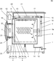
- FIG. 1 is a vertical cross-sectional view schematically showing the configuration of a drum-type washer-dryer according to the first embodiment of the dryer of the present disclosure.
- the drum-type washer-dryer 60 of the present embodiment has a function of washing and drying laundry such as clothes, and even as a washing machine that executes only the washing function, it is a dryer that executes only the drying function. However, it also functions as a washer / dryer that performs washing and drying functions.
- the drum-type washer-dryer 60 has a function of irradiating the laundry in the drum with microwaves, which is a kind of electromagnetic waves.
- microwaves which is a kind of electromagnetic waves.
- the drum type washer / dryer 60 includes two tanks, a water tank 2 as an outer tank and a drum 3 as a rotary tank.
- the water tank 2 is formed in a bottomed cylindrical shape and stores washing water.
- the water tank 2 is swingably supported in the housing 1 (main body) by a damper 4 provided below the water tank 2.
- the drum 3 is formed in a bottomed cylindrical shape, and accommodates laundry such as clothes (also referred to as a "drying object" when referring to the drying function).
- the drum 3 is rotatably provided in the water tank 2 and is provided so that the rotation axis is horizontal. In another example, the drum 3 may be provided so that the rotation axis is inclined forward with respect to the horizontal, or the rotation axis may be provided so as to be vertical.
- a drive motor 6a is attached to the bottom surface of the water tank 2 facing the back surface of the housing 1.
- the drive motor 6a rotates the drum 3 around the rotation axis in the forward direction and the reverse direction.
- the drum-type washer-dryer 60 performs stirring washing, rinsing, dehydration, and drying of the laundry contained in the drum 3 by the rotation of the drum 3 driven by the drive motor 6a.
- An opening 19 and a door body 5 for opening and closing the opening 19 are provided at positions facing the opening ends of the drum 3 and the water tank 2 on the front surface of the housing 1. The user can put in and take out the laundry with respect to the drum 3 by opening the door body 5.
- the water tank 2 has a water tank front portion 2a having a water tank opening 2c provided at a position facing the opening 19 of the housing 1 and a water tank rear portion 2b provided behind the water tank front portion 2a.
- An elastic tubular water sealing member 23 is provided so as to connect the edge of the water tank opening 2c of the water tank front portion 2a and the edge of the opening 19 over the entire circumference.
- the water tank front portion 2a may be a top surface portion of the water tank 2 formed in a bottomed cylindrical shape.
- the rear portion 2b of the water tank may be a side surface portion and a bottom surface portion of the cylinder.
- the water tank front portion 2a may include a portion in front of the side surface portion in addition to the top surface portion of the cylinder.
- the rear portion 2b of the water tank may be the remaining portion behind the side surface portion of the cylinder and the bottom surface portion.
- the rear portion 2b of the water tank may include a part of the side surface side of the top surface portion in addition to the side surface portion and the bottom surface portion of the water tank 2.
- the water tank front portion 2a may be the remaining portion of the top surface portion of the cylinder on the water tank opening 2c side.
- the water tank front portion 2a and the water tank rear portion 2b may be manufactured integrally, or may be manufactured separately, and the water tank 2 may be formed by connecting them. In the latter case, a water sealing member is similarly provided at the connecting portion between the water tank front portion 2a and the water tank rear portion 2b.
- a water supply pipe 13 is connected to the upper part of the water tank 2.
- a water supply valve 12 is provided in the middle of the water supply pipe 13.
- the water supply valve 12 supplies water into the water tank 2 via the water supply pipe 13.
- a drainage pipe 11 is connected to the lowermost part of the water tank 2.
- a drain valve 10 is provided in the middle of the drain pipe 11. The drain valve 10 discharges the water in the water tank 2 to the outside of the machine via the drain pipe 11.
- a damper 4 is provided below the water tank 2.
- the damper 4 supports the water tank 2 and damps the vibration of the water tank 2 generated due to the bias of the laundry in the drum 3 during dehydration or the like.
- a cloth amount detecting unit (not shown) is attached to the damper 4.
- the cloth amount detecting unit detects the amount of displacement in which the shaft of the damper 4 is displaced up and down due to a change in weight due to clothing or the like in the drum 3.
- the drum-type washer-dryer 60 detects the amount of clothes in the drum 3 based on the displacement amount detected by the cloth amount detecting unit.
- the drum 3 has a drum front portion 3a having a drum opening 3c provided at a position facing the opening 19 of the housing 1, and a drum rear portion 3b provided behind the drum front portion 3a.
- the drum front portion 3a may be a top surface portion of the drum 3 formed in a bottomed cylindrical shape.
- the drum rear portion 3b may be a side surface portion and a bottom surface portion of the cylinder.
- the drum front portion 3a may include a portion in front of the side surface portion in addition to the top surface portion of the cylinder.
- the drum rear portion 3b may be the remaining portion behind the side surface portion of the cylinder and the bottom surface portion.
- the drum rear portion 3b may include a portion of the side surface side of the top surface portion in addition to the side surface portion and the bottom surface portion of the drum 3.
- the drum front portion 3a may be the remaining portion of the top surface portion of the cylinder on the drum opening 3c side.
- the drum front portion 3a and the drum rear portion 3b may be manufactured integrally, or may be manufactured separately, and the drum 3 may be formed by connecting them.
- the drum-type washer-dryer 60 includes a circulation air passage 7 for circulating air in the water tank 2 and the drum 3, and a microwave irradiation unit 30 for irradiating the object to be dried in the drum 3 with microwaves.
- the microwave irradiation unit 30 constituting the heating unit for heating the object to be dried drums 3 microwaves from the microwave irradiation port 32 provided between the water tank opening 2c of the water tank 2 and the opening 19 of the housing 1. Irradiates the inside to heat the water contained in the object to be dried in the drum 3.
- the microwave irradiation unit 30 may be a microwave oscillator such as a magnetron, and oscillates an electromagnetic wave having a frequency in the 2.45 GHz band, for example.
- the electromagnetic wave is not limited to the 2.45 GHz band assigned as the ISM (Industry Science Medical) band, and may be an electromagnetic wave having a frequency such as the 915 MHz band similarly assigned.
- the microwave emitted from the microwave irradiation unit 30 is irradiated into the rotating drum 3 through the waveguide and the microwave irradiation port 32.
- a part of the microwaves that are not absorbed by the moisture contained in the object to be dried is reflected from the drum 3 through the microwave irradiation port 32 and is the microwave irradiation unit 30.
- Reflection portion may be provided. As a result, energy loss can be reduced and the drying time can be shortened.
- the circulation air passage 7 is configured as an air circulation air passage for drying the object to be dried in the drying step.
- the air circulation air passage includes a water tank 2 and a drum 3.
- the circulation air passage 7 is provided by connecting an air outlet 8 (drying air outlet) provided on the bottom surface of the water tank 2 and an outlet 9 (drying air outlet) provided in front of the side surface of the water tank 2. Has been done.
- the circulation air passage 7 is provided with a lint filter 22, a dehumidifying unit 21, a heater 17, and a blower fan 16 from the discharge port 9 side.
- the lint filter 22 is a filter having a nylon mesh, and captures lint contained in the air flowing through the circulation air passage 7.
- the dehumidifying unit 21 dehumidifies the air flowing through the circulation air passage 7.
- the dehumidifying unit 21 may be either a water-cooled type or an air-cooled type.
- the heater 17 heats the air flowing through the circulation air passage 7.
- the dehumidifying section 21 and the heater 17 may be composed of an evaporation section and a condensing section of the heat pump device.
- the blower fan 16 circulates the air in the water tank 2 and the drum 3 in the circulation air passage 7.
- the heater 17 and the microwave irradiation unit 30 constitute a heating unit for heating the object to be dried, and are energized to both or one of them at the same time.
- a method of heating the object to be dried by the heating unit a method of directly heating by microwaves, a method of heating the air circulating by a heater or the like, or a method of indirectly heating by heating the inner wall of the drum 3
- sparks will occur due to metal such as buttons and fasteners attached to the clothes to be dried, the output of microwaves emitted from the microwave irradiation unit 30 into the drum 3 will be reduced or stopped. Then, it is switched to the drying by the heater 17.
- the inflow temperature detection unit 18 is provided in the circulation air passage 7.
- the inflow temperature detection unit 18 detects the temperature of the air flowing into the drum 3.
- the inflow temperature detection unit 18 is composed of, for example, a thermistor or the like.
- the control device 20 is provided in the housing 1.
- the control device 20 controls the blower fan 16, the heater 17, the microwave irradiation unit 30, and the like.
- the control device 20 also controls the drive motor 6a, the water supply valve 12, the drain valve 10, and the like, and sequentially executes the washing, rinsing, dehydrating, and drying steps.
- a clothes dryer having no washing function is not provided with a water tank 2, a water supply valve 12, a water supply pipe 13, a drain valve 10, and a drain pipe 11 for storing washing water.
- the connection between the rotating drum 3 and the circulation air passage 7 is configured so that the drum 3 slides on a seal member such as felt.
- the drum-type washer-dryer 60 of the present embodiment microwaves are irradiated into the drum 3, so that the intensity of electromagnetic waves leaking to the outside of the drum-type washer-dryer 60 is a standard determined in the area where it is used. Must be configured to be less than or equal to the value. Therefore, the drum-type washer-dryer 60 of the present embodiment is provided with a shield portion for suppressing leakage of electromagnetic waves irradiated from the microwave irradiation port 32.
- JIS Japanese Industrial Standards
- microwave ovens with a rated high frequency output of 2 kW or less that heat foods with electromagnetic waves (microwaves) with a frequency of 2.45 GHz and microwave ovens with additional devices.
- C9250 There is "C9250”.
- the WHO World Health Organization
- ICNIRP International Commission on Non-Ionizing Radiation Protection
- This guideline stipulates that the exposure limit is 0.08 W / kg (1 mW / cm 2 ).
- the international standard "IEC62233" established by the International Electrotechnical Commission (IEC) and the Japanese Industrial Standard "JIS 1912" established based on it include the measurement of electromagnetic fields related to human exposure from household electrical equipment and similar equipment. The method is specified.
- the electromagnetic field is measured as a ratio to the exposure limit value by weighting the signal of the sensor that detects the electromagnetic field, and the exposure limit value specified in the ICNIRP guideline. If it does not exceed, it is judged that the guideline of ICNIRP is met.
- the shield portion is configured to comply with these standards.
- the storage chamber in which the object to be heated is housed is fixed, and large vibration does not occur during microwave irradiation.
- the drum-type washer-dryer 60 of the present embodiment the drying efficiency is improved. As a result, the drum 3 rotates during drying, and the drum 3 and the water tank 2 vibrate. Therefore, the shield portion of the drum-type washer-dryer 60 of the present embodiment can suppress microwaves leaking from the gap even if microwaves are irradiated while the drum 3 and the water tank 2 are vibrating. Has a structure.
- FIG. 2 shows the configuration of the shield portion of the drum-type washer-dryer 60 according to the first embodiment.
- FIG. 2 is a diagram in which a part of the configuration of the drum-type washer-dryer 60 according to the first embodiment shown in FIG. 1 is omitted.
- the members constituting the shield portion are shaded.
- the shield portion includes a door body 5, an opening 19, a water tank front portion 2a, a cover portion 24, and a water tank rear portion 2b.
- the cover portion 24 is a member that covers the space between the opening 19 and the front portion 2a of the water tank.
- the door body 5, the opening 19, the water tank front part 2a, and the water tank rear part 2b contain a conductive material such as a metal capable of reflecting or absorbing microwaves.
- the door body 5, the opening 19, the water tank front portion 2a, or the water tank rear portion 2b may be entirely formed of an electromagnetic wave shielding material such as a conductive material.
- the door body 5, the opening 19, the water tank front portion 2a, or the water tank rear portion 2b may be formed of a material such as resin, and a plating layer of a conductive material may be provided on the inner surface or the outer surface.
- the door body 5, the opening 19, the water tank front portion 2a, or the water tank rear portion 2b may be formed of a material such as resin, and a layer of an electromagnetic wave shielding material may be provided on the inner surface, the outer surface, or the inside.
- the opening 19 of the housing 1 and the water tank front portion 2a of the water tank 2 are separated, watertightness is ensured by the water sealing member 23, and the space between them is formed of an electromagnetic wave shielding material. It is covered by the covered cover portion 24. That is, when the cover portion 24 having conductivity and flexibility is provided, the drum 3 rotates and vibrates, and even if the water tank 2 vibrates due to this, when the object to be dried is dried by irradiating electromagnetic waves. It is possible to provide a drum-type washer-dryer 60 capable of suppressing leakage of electromagnetic waves.
- the cover portion 24 is made of a flexible face material.
- the opening 19 and the door body 5 of the housing 1 are separated from the water tank 2 that vibrates due to the rotation of the drum 3, so that the vibration of the water tank 2 is difficult to transmit. Therefore, it is possible to prevent the space between the door body 5 and the opening 19 from expanding due to vibration and the microwave from leaking from the gap.
- the microwave irradiation unit 30 can be installed in the housing 1 having a small vibration instead of being installed in the water tank 2 or the drum 3 having a large vibration, the microwave oscillator such as a magnetron can be protected from the vibration. It is possible to improve the oscillation performance and durability of microwaves.
- some configurations such as a microwave oscillator and a waveguide may be installed in the housing 1.
- the cover portion 24 is made of a flexible face material. As a result, processing and mounting can be facilitated, so that the manufacturing cost can be reduced.
- One end of the face material is fixed to the opening 19 of the housing 1, and the other end is fixed to the front portion 2a of the water tank 2.
- the face material may be fixed by another face material such as a belt, or may be fixed by a wire material such as a wire. In this case, the face material may be fixed by pressing the face material from the outside of the face material with a belt, a wire, or the like. As a result, the configuration for fixing the face material can be simplified and the manufacturing cost can be reduced.
- the face material may be fixed by forming the end of the face material in a bag shape and passing a belt, a wire or the like through the bag.
- the work for fixing the face material can be simplified, the manufacturing cost can be reduced, and the stability of the contacts can be improved.
- the cover portion 24 may be formed in a tubular shape by using an elastic material.
- the face material constituting the cover portion 24 may be a conductive cloth or mesh material. Further, the face material may be formed by knitting a string-shaped cloth.
- the vibration of the water tank 2 can be made difficult to be transmitted by the opening 19 of the housing 1 and the door body 5.
- the manufacturing cost can be reduced.
- the cover portion 24 may be formed in a bellows tubular shape or a mesh shape depending on the face material.
- the face material constituting the cover portion 24 may be made of a conductive material having no elasticity. Even if the material does not have elasticity, it can be expanded and contracted by forming it in a bellows tubular shape or a mesh shape, so that the vibration of the water tank 2 is transmitted by the opening 19 of the housing 1 and the door body 5. It can be made difficult. Further, since the choice of the face material that can be used as the cover portion 24 can be expanded, the manufacturing cost can be reduced. In this case as well, the face material may be a conductive cloth or a mesh material, or may be formed by knitting a string-shaped cloth.
- the cover portion 24 may be provided on the outside of the water sealing member 23.
- a chlorine-based bleaching agent is used during washing, if the washing water containing chlorine adheres to the cover portion 24, the conductive material may be corroded by chlorine.
- the cover portion 24 by providing the cover portion 24 on the outside of the water sealing member 23, it is possible to prevent moisture from adhering to the cover portion 24, so that the electromagnetic wave shielding performance and durability of the cover portion 24 can be suppressed from deteriorating. Can be done. Further, since the cover portion 24 can be easily incorporated, the manufacturing cost can be reduced.
- the cover portion 24 may be provided inside the water sealing member 23.
- the exposure of electromagnetic waves to the water sealing member 23 can be suppressed, so that the watertightness, airtightness, and durability of the water sealing member 23 can be suppressed from being lowered.
- the cover portion 24 may also be used as the water sealing member 23.
- the face material constituting the cover portion 24 may be formed of a conductive elastomer.
- the water tank front part 2a and the water tank rear part 2b may be integrally formed or may be manufactured separately and connected.
- the shield portion includes the rear portion 2b of the water tank as in the present embodiment, the entire water tank 2 may be formed of a conductive material, and the configuration of the drum type washer-dryer 60 can be simplified. The cost can be reduced.
- the water tank 2 is fixed by sandwiching the waterproof member and the conductive member between the water tank front portion 2a and the water tank rear portion 2b. With this configuration, leakage of electromagnetic waves can be suppressed while ensuring watertightness.
- FIG. 3 is a cross-sectional view of a main part of the connecting portion between the water tank front portion 2a and the water tank rear portion 2b of the drum-type washer-dryer 60 according to the first embodiment.
- the rear portion 2b of the water tank is the main body of the water tank forming the side surface portion and the bottom surface portion of the cylinder
- the front portion 2a of the water tank is the water tank cover forming the top surface portion of the cylinder.
- the waterproof member accommodating portion 49 and the conductive member accommodating portion 50 are provided on the end surface 47 of the water tank rear side connecting portion.
- the waterproof member accommodating portion 49 accommodates the waterproof member 51, and the conductive member accommodating portion 50 accommodates the conductive member 52.
- the position of the conductive member accommodating portion 50 is on the outer peripheral side of the waterproof member accommodating portion 49 with respect to the rotation axis of the drum 3.
- the end surface 48 of the connecting portion on the front side of the water tank has a waterproof member contact portion 53 that contacts the waterproof member 51 and a conductive member that contacts the conductive member 52.
- a contact portion 54 is provided.
- FIG. 4 is a cross-sectional view of a main part of the end surface (cross-section AA) of the connecting portion on the rear side of the water tank.
- the waterproof member 51 uses a substantially annular packing or sealing material such as an O-ring.
- As the conductive member 52 for example, a substantially annular conductive rubber or a metal-plated conductive cloth is used. It is desirable that the waterproof member 51 and the conductive member 52 have a continuous substantially annular shape, but if the effect of preventing water and microwave leakage can be ensured, the waterproof member 51 and the conductive member 52 are arranged in a discontinuous substantially annular shape on the end surface 47 of the connecting portion on the rear side of the water tank. It may have been.
- FIG. 5 is a cross-sectional view of a main part of another example of the connecting portion between the water tank front portion 2a and the water tank rear portion 2b of the drum-type washer-dryer 60 according to the first embodiment.
- the waterproof member accommodating portion 49 and the conductive member accommodating portion 50 are integrated, and the conductive member 52 is provided on the outer peripheral side of the waterproof member 51 so as to be in close contact with the waterproof member 51. ing.
- the structure of the connecting portion between the water tank front portion 2a and the water tank rear portion 2b can be reduced.
- FIG. 6 is a cross-sectional view of a main part of still another example of the connecting portion between the water tank front portion 2a and the water tank rear portion 2b of the drum type washer-dryer 60 according to the first embodiment.
- the waterproof member accommodating portion 49 and the conductive member accommodating portion 50 are integrated, and the end surface thereof is smooth.
- the waterproof member contact portion 53 projects rearward from the water tank rear side connecting portion end surface 47.
- the conductive member 52 is provided on the outer peripheral side of the waterproof member 51 so as to be in close contact with the waterproof member 51. As a result, it is not necessary to form a recess in the metal water tank rear side connecting portion end surface 47, so that the molding of the water tank rear side connecting portion end surface 47 can be facilitated and the manufacturing cost can be reduced.
- the conductive member 52 is provided on the outside of the waterproof member 51, it is possible to prevent moisture from adhering to the conductive member 52 as in the case of the cover portion 24.
- the conductive material may be corroded by chlorine.
- the conductive member 52 may be provided inside the waterproof member 51.
- the exposure of electromagnetic waves to the waterproof member 51 can be suppressed, so that the watertightness and durability of the waterproof member 51 can be suppressed from being lowered.
- the conductive member 52 and the waterproof member 51 may be used in combination.
- the member having both the functions of the conductive member 52 and the waterproof member 51 may be formed of a conductive elastomer.
- a gap may be generated due to a dimensional error, vibration, or the like as long as the gap is such that microwaves do not leak.
- the cover portion 24 or the connecting portion between the water tank front portion 2a and the water tank rear portion 2b may be fixed by screws or the like at intervals such that microwaves do not leak.
- the shield portion for suppressing leakage of microwaves from the housing 1 is at least the door body 5, the opening 19, and the front of the water tank.
- a portion 2a, a cover portion 24, and a water tank rear portion 2b are included.
- the shield portion includes the rear portion 2b of the water tank
- the water tank 2 may be entirely formed of a conductive material.
- the water tank 2 may be configured so as to sandwich and fix a waterproof member and a conductive member between the water tank front portion 2a and the water tank rear portion 2b. As a result, leakage of electromagnetic waves can be suppressed while ensuring watertightness of the water tank 2.
- cover portion 24 may be formed in a tubular shape with a face material having conductivity and flexibility. As a result, the manufacturing cost of the drum-type washer-dryer 60 can be reduced.
- cover portion 24 may be formed in a bellows tubular shape with a face material having conductivity. As a result, the manufacturing cost of the drum-type washer-dryer 60 can be reduced.
- the cover portion 24 may be provided at least on either the outside or the inside of the water sealing member 23. That is, by providing the cover portion 24 on the outside of the water sealing member 23, it is possible to suppress deterioration of the electromagnetic wave shielding performance and durability of the cover portion 24. Further, by providing the cover portion 24 inside the water sealing member 23, it is possible to prevent the water sealing member 23 from being deteriorated in watertightness, airtightness and durability. Further, the cover portion 24 may also be used as the water sealing member 23. As a result, the manufacturing cost of the drum-type washer-dryer 60 can be reduced.
- the face material constituting the cover portion 24 may be formed of a conductive cloth or mesh material. As a result, the manufacturing cost of the drum-type washer-dryer 60 can be reduced.
- the face material constituting the cover portion 24 may be formed by knitting a string-shaped cloth. As a result, the manufacturing cost of the drum-type washer-dryer 60 can be reduced.
- the face material constituting the cover portion 24 may be formed of a conductive elastomer.
- the cover portion 24 can also be used as the water sealing member 23.
- FIG. 7 is a vertical cross-sectional view schematically showing the configuration of the drum type washer-dryer according to the second embodiment of the dryer of the present disclosure.
- the drum-type washer-dryer 60 according to the second embodiment includes a choke portion 25 in addition to the configuration of the drum-type washer-dryer 60 according to the first embodiment shown in FIG.
- Other configurations and operations are the same as those in the first embodiment. The points different from the first embodiment will be mainly described.
- FIG. 8 shows the configuration of the shield portion of the drum type washer-dryer 60 according to the second embodiment.
- FIG. 8 is a diagram in which a part of the configuration of the drum-type washer-dryer 60 according to the second embodiment shown in FIG. 7 is omitted.
- the members constituting the shield portion are shaded.
- the shield portion includes a door body 5, an opening 19, a water tank front portion 2a, a cover portion 24, and a drum 3.
- the drum 3 contains a conductive material such as a metal capable of reflecting or absorbing microwaves.
- the drum 3 may be entirely formed of an electromagnetic wave shielding material such as a conductive material.
- the drum 3 may be made of a material such as resin, and a plating layer of a conductive material may be provided on the inner surface or the outer surface.
- the drum 3 may be made of a material such as resin, and may be provided with a layer of an electromagnetic wave shielding material on the inner surface, the outer surface, or the inside.
- the rear portion 3b of the drum is provided with a large number of holes through which water and air can pass, and these holes are formed in a size such that microwaves do not leak.
- the shield portion is formed by the drum 3 instead of the water tank rear portion 2b, so that the water tank front portion 2a and the drum front portion are formed. There is a gap between it and 3a. Therefore, in order to prevent microwaves from leaking from this gap, a gap shield portion is provided.
- the gap shield portion there is a choke structure which is a non-contact type microwave shield.
- a choke portion 25 is formed between the water tank front portion 2a and the drum front portion 3a.
- the choke portion 25 may be provided on either the water tank front portion 2a or the drum front portion 3a.
- any choke structure known in a technical field such as a microwave oven can be adopted.
- the choke structure may be composed of a plurality of chokes.
- the plurality of chokes the leakage of microwaves can be suppressed in a plurality of stages, and the performance of preventing the leakage is improved.
- the plurality of chokes may have different dimensions or shapes of each choke, and may be composed of, for example, stepped chokes.
- the amount and weight of the object to be dried vary, and the weight changes between the initial stage and the end of the drying operation. Then, during the drying operation, the drum 3 rotates and vibrates, and the size of the gap between the water tank front portion 2a and the drum front portion 3a constituting the choke portion 25 may change.
- the microwave frequency may change depending on the operating conditions. In devising the dimensions or shape of the step choke, dimensional changes during operation and manufacturing variations may be taken into consideration. Further, the case where the frequency of the microwave changes depending on the operating condition may be considered. Therefore, according to the step choke, the performance of preventing the leakage of microwaves is further improved. As described above, in the drum type washer-dryer 60, the leakage prevention structure by a plurality of stages is extremely effective.
- the choke structure may be configured by filling at least a part of the groove space that generates the reflected wave with resin.
- the choke structure can be made thinner or smaller, so that the size of the gap between the water tank front portion 2a and the drum front portion 3a constituting the choke portion 25 can be reduced, and the volume of the drum 3 can be reduced by the choke portion 25. Can be suppressed.
- the gap shield portion may be provided with an absorption type microwave shield such as a dielectric instead of the reflection type microwave shield such as a choke structure.
- a non-contact type microwave shield of any type may be provided as a gap shield portion.
- the gap shield portion may be a contact type microwave shield.
- it may be a point contact microwave shield such as a ball bearing, or a line contact microwave shield such as a rolling bearing.
- the contact interval may be configured to be half or less of the wavelength of the microwave to be shielded.
- the gap shield portion may be a surface contact microwave shield such as a slide bearing.
- a flexible microwave shield may be provided as the gap shield portion.
- a conductive lubricant may be used as the lubricating oil for the bearing. As a result, the leakage of microwaves can be further suppressed.
- the gap shield portion may include a plurality of microwave shields.
- the gap shield portion may include only the contact type microwave shield, may include only the non-contact type microwave shield, or may include the contact type microwave shield and the non-contact type microwave shield. Both may be included.
- each microwave shield may be a reflection type microwave shield or an absorption type microwave shield.
- the innermost gap shield portion is a reflective microwave shield.
- the outer gap shield portion may be a reflection type microwave shield or an absorption type microwave shield.
- the shield portion for suppressing the leakage of microwaves from the housing 1 is at least the door body 5, the opening 19, and the front of the water tank.
- the portion 2a, the cover portion 24, and the drum 3 are included. With this configuration, even if the drum 3 rotates and the water tank 2 vibrates, the leakage of electromagnetic waves can be suppressed.
- the drum 3 may be formed entirely of a conductive material, and the shield portion may be configured to include a gap shield portion formed between the drum front portion 3a and the water tank front portion 2a.
- the gap shield portion may be formed of a choke structure (choke portion 25) or a bearing.
- the water tank 2 can be formed of resin or the like. That is, in the conventional product, the drum 3 usually formed of metal is used as the shield portion, and the water tank 2 can be formed of an inexpensive material such as resin, so that the manufacturing cost of the drum type washer-dryer 60 can be reduced. Can be done.
- the choke portion 25 may be configured to include at least one of a plurality of chokes or a stepped choke. As a result, the performance of suppressing the leakage of electromagnetic waves is improved.
- the choke portion 25 may be configured by filling at least a part of the groove space with resin. As a result, the choke portion 25 can be made thinner or smaller.
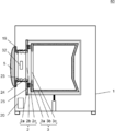
- FIG. 9 is a vertical cross-sectional view schematically showing the configuration of the drum type washer-dryer according to the third embodiment of the dryer of the present disclosure.
- the drum-type washer-dryer 60 according to the third embodiment is provided with a water tank lid 15 by omitting the cover portion 24 as compared with the drum-type washer-dryer 60 according to the first embodiment shown in FIG.
- the water tank lid 15 is a lid of the water tank 2 which is an outer tank, and is an example of the outer tank lid.
- Other configurations and operations are the same as those in the first embodiment. The points different from the first embodiment will be mainly described.
- the water tank lid 15 is provided in the water tank opening 2c of the water tank 2. Although not shown, the water tank lid 15 may be configured to open and close in conjunction with the opening and closing of the door body 5. For example, a link mechanism for interlocking the connection portion between the water tank lid 15 and the door body 5 is required, but the user can put the laundry in and out of the drum 3 simply by opening the door body 5. Because it can be used, usability is improved.
- An elastic tubular water sealing member 23 is provided on the opening edge of the water tank opening 2c so that the water tank lid 15 is in close contact with the entire circumference.
- the water sealing member 23 is pressed by the water tank lid 15 and elastically deformed, so that the watertightness of the water tank 2 with respect to the outside of the machine is ensured.
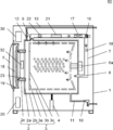
- FIG. 10 shows the configuration of the shield portion of the drum type washer-dryer 60 according to the third embodiment.
- FIG. 10 is a diagram in which a part of the configuration of the drum-type washer-dryer 60 according to the third embodiment shown in FIG. 9 is omitted.
- the members constituting the shield portion are shaded.
- the shield portion includes the water tank lid 15, the water tank front part 2a including the water tank opening 2c, and the water tank rear part 2b.
- the water tank lid 15, the water tank front part 2a, and the water tank rear part 2b contain a conductive material such as a metal capable of reflecting or absorbing microwaves.
- the water tank lid 15, the water tank front portion 2a, or the water tank rear portion 2b may be entirely formed of an electromagnetic wave shielding material such as a conductive material.
- the water tank lid 15, the water tank front portion 2a, or the water tank rear portion 2b may be formed of a material such as resin, and a plating layer of a conductive material may be provided on the inner surface or the outer surface.
- the water tank lid 15, the water tank front portion 2a, or the water tank rear portion 2b may be formed of a material such as resin, and a layer of an electromagnetic wave shielding material may be provided on the inner surface, the outer surface, or the inside.
- the opening 19 of the housing 1 and the water tank front portion 2a of the water tank 2 are separated, a water tank lid 15 is provided on the water tank front portion 2a, and the water tank 2 is watertightened by a water sealing member 23.
- the opening 19 and the door body 5 of the housing 1 are separated from the water tank 2 that vibrates due to the rotation of the drum 3, so that the vibration of the water tank 2 is difficult to transmit.
- the housing 1, the opening 19 and the door body 5 do not require a configuration for preventing the leakage of microwaves. That is, with this configuration, it is possible to provide a drum-type washer-dryer 60 capable of suppressing leakage of electromagnetic waves even if the drum 3 rotates and the water tank 2 vibrates.
- the drum type washer-dryer 60 capable of suppressing the leakage of electromagnetic waves is manufactured at low cost. can do.
- the door body 5 of the housing 1 does not necessarily have to be provided.
- the opening 19 of the housing 1 may be configured so that the vibration of the water tank 2 does not adversely affect the user.
- a door body instead of the water tank lid 15 provided in the water tank opening 2c, a door body may be provided in the drum opening 3c of the drum 3.
- the microwave may be irradiated into the drum 3 through the inside of the rotation shaft of the drum 3, and the entire drum 3 including the door body provided in the drum opening 3c may form the shield portion.
- the control device 20 is configured so that the drum 3 is stopped rotating at a predetermined position and the opening / closing direction of the door body at that time is substantially uniform.
- the shield portion for suppressing leakage of microwaves from the housing is at least the water tank lid 15, the water tank front part 2a, and the water tank rear part. It is configured to include 2b. With this configuration, even if the water tank 2 vibrates, leakage of electromagnetic waves can be suppressed, and the drum-type washer-dryer 60 can be manufactured at low cost.
- the water tank lid 15 may be configured to open and close in conjunction with the opening and closing of the door body 5. As a result, the usability of the user is improved.
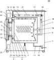
- FIG. 11 is a vertical cross-sectional view schematically showing the configuration of the drum-type washer-dryer according to the fourth embodiment of the dryer of the present disclosure.
- the drum-type washer-dryer 60 according to the fourth embodiment is provided with a water tank lid 15 by omitting the cover portion 24 as compared with the configuration of the drum-type washer-dryer 60 according to the second embodiment shown in FIG. ..
- a choke portion 25 is provided in addition to the configuration of the drum-type washer-dryer 60 according to the third embodiment shown in FIG. 9, a choke portion 25 is provided.
- Other configurations and operations are the same as those in the first to third embodiments. The points different from the first to third embodiments will be mainly described.
- FIG. 12 shows the configuration of the shield portion of the drum type washer-dryer 60 according to the fourth embodiment.
- FIG. 12 is a diagram in which a part of the configuration of the drum-type washer-dryer 60 according to the fourth embodiment shown in FIG. 11 is omitted.
- the members constituting the shield portion are shaded.
- the shield portion includes the water tank lid 15, the water tank front portion 2a, and the drum 3.
- the drum 3 contains a conductive material such as a metal capable of reflecting or absorbing microwaves.
- the drum 3 may be entirely formed of an electromagnetic wave shielding material such as a conductive material.
- the drum 3 may be made of a material such as resin, and a plating layer of a conductive material may be provided on the inner surface or the outer surface.
- the drum 3 may be made of a material such as resin, and may be provided with a layer of an electromagnetic wave shielding material on the inner surface, the outer surface, or the inside.
- the rear portion 3b of the drum is provided with a large number of holes through which water and air can pass, and these holes are formed in a size such that microwaves do not leak.
- the shield portion is formed by the drum 3 instead of the water tank rear portion 2b, so that the water tank front portion 2a and the drum front portion are formed. There is a gap between it and 3a. Therefore, in order to prevent microwaves from leaking from this gap, a gap shield portion is provided.
- the gap shield portion there is a choke structure which is a non-contact type microwave shield.
- a choke portion 25 is formed between the water tank front portion 2a and the drum front portion 3a.
- any choke structure known in the technical field such as a microwave oven can be adopted.
- the details of the gap shield portion are the same as those in the second embodiment.
- the shield portion for suppressing leakage of microwaves from the housing is at least the water tank lid 15, the water tank front portion 2a, and the drum 3. Consists of including. With this configuration, even if the water tank 2 vibrates, leakage of electromagnetic waves can be suppressed.
- the drum 3 usually formed of metal is used as the shield portion, and the water tank 2 can be formed of an inexpensive material such as resin, so that the manufacturing cost of the drum type washer-dryer 60 can be reduced. Can be done.
- FIG. 13 is a vertical cross-sectional view schematically showing the configuration of the vertical washer / dryer 70 according to the fifth embodiment of the dryer of the present disclosure.
- the rotation axis of the drum 3 is configured in the vertical direction, and a pulsator 14 for stirring the laundry and the washing water is provided at the bottom position of the drum 3.
- Other configurations and operations are the same as those of the drum type washer-dryer 60 of the first and third embodiments. The points different from the first and third embodiments will be mainly described.
- the rotation axis of the drum 3 is vertical. Therefore, the water tank 2 and the drum 3 of the drum type washer / dryer 60 described in the first embodiment or the third embodiment.
- the "front” direction is the "up” direction
- the "rear, back” direction is the “down, bottom” direction. If the water tank 2 and the drum 3 of the drum-type washer-dryer 60 of the first and third embodiments shown in FIGS. 1 to 6 and 9 to 10 are rotated 90 degrees to the right, the vertical washer-dryer 70 can be applied. ..
- the drum 3 does not rotate, but the pulsator 14 rotates in the forward direction and the reverse direction, so that the laundry contained in the drum 3 is agitated. Wash, rinse, and dry.
- FIG. 14 shows the configuration of the shield portion of the vertical washer / dryer 70 according to the fifth embodiment.
- FIG. 14 is a diagram in which a part of the configuration of the vertical washer / dryer 70 according to the fifth embodiment shown in FIG. 13 is omitted.
- the members constituting the shield portion are shaded.
- the shield portion includes the water tank lid 15, the water tank front part 2a including the water tank opening 2c, and the water tank rear part 2b.
- the vertical washer / dryer 70 of the present embodiment can also suppress the leakage of microwaves even if the water tank 2 vibrates, like the drum-type washer / dryer 60 of the first and third embodiments.
- FIG. 15 is a vertical cross-sectional view schematically showing the configuration of the drum type washer-dryer 60 according to the sixth embodiment of the dryer of the present disclosure.
- the drum-type washer-dryer 60 of the present embodiment has a vibration-proof mechanism for suppressing vibration of the housing 1 and the drum 3, a cover portion 24, and a water-sealing member 23. Different from machine 60. Other configurations and operations are the same as those in the first embodiment. The points different from the first embodiment will be mainly described.
- an opening 19 and a door body 5 for opening and closing the opening 19 are provided on the front surface of the housing 1.
- a water tank 2 having a bottomed cylindrical shape in which wash water is stored is provided inside the housing 1.
- the water tank 2 is fixed to the housing 1 by fixing the water tank opening 2c and the opening 19 provided at positions facing the opening 19 of the housing 1.
- the bottom surface of the water tank 2 (the surface facing the back surface of the housing 1 in FIG. 15) is composed of a plurality of members. The details will be described later.
- An elastic tubular door packing 23a is provided all around the inside of the opening 19 of the housing 1. The user can put in and take out the laundry with respect to the drum 3 by opening the door body 5. When the user closes the door body 5, the door packing 23a is pressed by the door body 5 and elastically deformed, so that the watertightness of the water tank 2 with respect to the outside of the machine is ensured.
- the water tank 2 has a water tank front portion 2a having a water tank opening 2c and a water tank rear portion 2b provided behind the water tank front portion 2a.
- the water tank front portion 2a may include a part of the side surface side of the bottom surface portion in addition to the top surface portion and the side surface portion of the cylinder. In that case, the rear portion 2b of the water tank may be the remaining portion on the central side of the bottom surface portion.
- the drum front portion 3a may include a part of the side surface side of the bottom surface portion in addition to the top surface portion and the side surface portion of the drum 3.
- the drum rear portion 3b may be the remaining portion of the bottom surface portion on the rotation axis side.
- a drum drive unit 6 that rotationally drives the drum 3 is attached to the bottom surface of the drum 3.
- the drum drive unit 6 has a drive motor 6a, a rotary shaft 6b that connects the drum 3 and the drive motor 6a, and a bearing portion 6c that supports the rotary shaft 6b.
- the bearing portion 6c is configured to support the rotary shaft 6b with a plurality of bearings.
- the drive motor 6a rotates the drum 3 around the rotation axis in the forward direction and the reverse direction.
- the drum-type washer-dryer 60 performs stirring washing, rinsing, dehydration, and drying of the laundry contained in the drum 3 by the rotation of the drum 3 driven by the drive motor 6a.
- the bottom surface of the water tank 2 is composed of a plurality of members. That is, the bottom surface of the water tank 2 itself is opened on the central side, leaving the side surface side, and a part of the vibration isolation mechanism 40 is incorporated in the opening portion.
- the anti-vibration mechanism 40 includes a motor support portion 26, a plurality of dampers (lower damper 4a and upper damper 4b) provided between the motor support portion 26 and the housing 1, a flexible water sealing member 23, and the like. including.
- a drum drive unit 6 is fixed to the motor support unit 26.
- the motor support portion 26 is located at the opening portion on the bottom surface of the water tank 2, and is provided so as to close the opening via a water sealing member 23 provided with flexibility and watertightness. As described above, the bottom surface of the water tank 2 includes the motor support portion 26 and the water sealing member 23.
- the plurality of dampers support the drum drive unit 6 and the drum 3 from the housing 1 via the motor support unit 26.
- the plurality of dampers include two lower dampers 4a that support the lower left and right lower parts of the motor support portion 26 from the bottom portion of the housing 1, and an upper damper 4b that supports the upper portion of the motor support portion 26 from the rear portion of the housing 1. Provided.
- the lower damper 4a mainly absorbs the vertical and horizontal vibrations of the motor support portion 26, and the upper damper 4b mainly absorbs the front-rear vibrations of the motor support portion 26.
- the vibration of the drum 3 is damped and the vibration transmission to the housing 1 is suppressed.
- the vibration isolation mechanism 40 configured in this way, the vibration of the drum 3 that houses and rotates the laundry is transmitted to the motor support portion 26, but the vibration transmission to the housing 1 is transmitted to the lower damper 4a and the upper damper 4b.
- the vibration transmission to the water tank 2 fixed to the housing 1 is suppressed by the water sealing member 23.
- a cloth amount detection unit (not shown) may be attached to the lower damper 4a.
- the cloth amount detecting unit detects the amount of displacement in which the axis of the lower damper 4a is displaced up and down due to a change in weight due to clothing or the like in the drum 3.
- the drum-type washer-dryer 60 detects the amount of clothes in the drum 3 based on the displacement amount detected by the cloth amount detecting unit.
- the position and number of dampers and the shape of the motor support portion 26 are not particularly limited. In short, it suffices if the load of the rotating drum 3 or the like can be reliably supported and the vibration in all directions can be accurately damped.
- FIG. 16 shows the configuration of the shield portion of the drum type washer / dryer 60 according to the sixth embodiment.
- FIG. 16 is a diagram in which a part of the configuration of the drum-type washer-dryer 60 according to the sixth embodiment shown in FIG. 15 is omitted.
- the members constituting the shield portion are shaded.
- the shield portion includes a door body 5, an opening 19, a water tank front portion 2a, a cover portion 24, and a water tank rear portion 2b.
- the cover portion 24 may be included in the rear portion 2b of the water tank.
- the cover portion 24 is provided so as to cover the water sealing member 23 on the outside of the water tank 2 from the water sealing member 23 in parallel with the water sealing member 23.
- the bottom surface of the water tank 2 is configured to include the motor support portion 26 and the water sealing member 23, the water sealing member 23 ensures watertightness, and the water sealing member 23 is formed of an electromagnetic wave shielding material. It is covered by the covered cover portion 24.
- the cover portion 24 is made of a face material having conductivity and flexibility.
- the drum 3 rotates and vibrates, and even if the motor support portion 26 and the water tank 2 vibrate due to this, the object to be dried by irradiating electromagnetic waves. It is possible to provide a drum-type washer-dryer 60 capable of suppressing leakage of electromagnetic waves when drying an object.
- the microwave irradiation unit 30 can be installed in the housing 1 or the water tank 2 where the vibration is small, the microwave oscillator such as a magnetron can be protected from the vibration, and the microwave oscillation performance and durability can be improved. Can be improved.
- some configurations such as a microwave oscillator and a waveguide may be installed in the housing 1 or the water tank 2.
- the cover portion 24 is made of a flexible face material. As a result, processing and mounting can be facilitated, so that the manufacturing cost can be reduced.
- One end of the face material is fixed to the entire circumference of the opening on the bottom surface of the water tank 2, and the other end is fixed to the motor support portion 26.
- the face material may be fixed by another face material such as a belt, or may be fixed by a wire material such as a wire. In this case, the face material may be fixed by pressing the face material from the outside of the face material with a belt, a wire, or the like. As a result, the configuration for fixing the face material can be simplified and the manufacturing cost can be reduced.
- the face material may be fixed by forming the end of the face material in a bag shape and passing a belt, a wire or the like through the bag.
- the work for fixing the face material can be simplified, the manufacturing cost can be reduced, and the stability of the contacts can be improved.
- the cover portion 24 may be formed in a donut shape having a space on the center side by using an elastic material.
- the face material constituting the cover portion 24 may be a conductive cloth or mesh material. Further, the face material may be formed by knitting a string-shaped cloth. As a result, the vibration of the drum 3 can be made difficult to be transmitted by the housing 1. In addition, since processing and mounting can be facilitated, the manufacturing cost can be reduced.
- the cover portion 24 may be provided on the outside of the water sealing member 23.
- a chlorine-based bleaching agent is used during washing, if the washing water containing chlorine adheres to the cover portion 24, the conductive material may be corroded by chlorine.
- the cover portion 24 by providing the cover portion 24 on the outside of the water sealing member 23, it is possible to prevent moisture from adhering to the cover portion 24, so that the electromagnetic wave shielding performance and durability of the cover portion 24 can be suppressed from deteriorating. Can be done. Further, since the cover portion 24 can be easily incorporated, the manufacturing cost can be reduced.
- the cover portion 24 may be provided inside the water sealing member 23.
- the exposure of electromagnetic waves to the water sealing member 23 can be suppressed, so that the watertightness, airtightness, and durability of the water sealing member 23 can be suppressed from being lowered.
- the cover portion 24 may also be used as the water sealing member 23.
- the face material constituting the cover portion 24 may be formed of a conductive elastomer.
- the cover portion 24 may be provided at substantially the same position as the water sealing member 23, and may be provided so as to follow the flexibility of the water sealing member 23 and prevent electromagnetic waves from leaking.
- the water tank 2 is configured so as to sandwich and fix the waterproof member and the conductive member between the water tank front portion 2a and the water tank rear portion 2b.
- the cover portion 24 having flexibility is provided at substantially the same position as the water sealing member 23 on the bottom surface of the water tank 2.
- a choke structure as described in the second embodiment may be provided instead of the cover portion 24.
- a choke structure may be provided in addition to the cover portion 24.
- the shield portion for suppressing leakage of microwaves from the housing 1 is at least the door body 5, the opening 19, and the front of the water tank.
- the portion 2a and the rear portion 2b of the water tank are included.
- the water tank 2 is provided with a flexible cover portion 24 at substantially the same position as the water sealing member 23, and the entire water tank 2 including the cover portion 24 and the motor support portion 26 is formed of a conductive material.
- the cover portion 24 is made of a face material having conductivity and flexibility and is formed in a donut shape. As a result, the manufacturing cost of the drum-type washer-dryer 60 can be reduced.
- FIG. 17 is a vertical cross-sectional view schematically showing the configuration of the drum type washer-dryer according to the seventh embodiment of the dryer of the present disclosure.
- the drum-type washer-dryer 60 according to the seventh embodiment includes a choke portion 25 in addition to the configuration of the drum-type washer-dryer 60 according to the sixth embodiment shown in FIG.
- Other configurations and operations are the same as those of the first, second and sixth embodiments. The differences from the first, second, and sixth embodiments will be mainly described.
- FIG. 18 shows the configuration of the shield portion of the drum type washer / dryer 60 according to the seventh embodiment.
- FIG. 18 is a diagram in which a part of the configuration of the drum-type washer-dryer 60 according to the seventh embodiment shown in FIG. 17 is omitted.
- the members constituting the shield portion are shaded.
- the shield portion includes a door body 5, an opening 19, a water tank front portion 2a, and a drum 3.
- the drum 3 contains a conductive material such as a metal capable of reflecting or absorbing microwaves.
- the drum 3 may be entirely formed of an electromagnetic wave shielding material such as a conductive material.
- the drum 3 may be made of a material such as resin, and a plating layer of a conductive material may be provided on the inner surface or the outer surface.
- the drum 3 may be made of a material such as resin, and may be provided with a layer of an electromagnetic wave shielding material on the inner surface, the outer surface, or the inside.
- the rear portion 3b of the drum is provided with a large number of holes through which water and air can pass, and these holes are formed in a size such that microwaves do not leak.
- the shield portion is formed by the drum 3 instead of the water tank rear portion 2b, so that the water tank front portion 2a and the drum front portion are formed. There is a gap between it and 3a. Therefore, in order to prevent microwaves from leaking from this gap, a gap shield portion is provided.
- the gap shield portion there is a choke structure which is a non-contact type microwave shield.
- a choke portion 25 which is an example of the gap shield portion is formed between the water tank front portion 2a and the drum front portion 3a. ..
- any choke structure known in the technical field such as a microwave oven can be adopted.
- the details of the gap shield portion are the same as those in the second embodiment.
- the shield portion for suppressing leakage of microwaves from the housing 1 is at least the door body 5, the opening 19, and the front of the water tank.
- a portion 2a and a drum 3 are included.
- the drum 3 may be formed entirely of a conductive material, and the shield portion may be configured to include a gap shield portion formed by the drum front portion 3a and the water tank front portion 2a.
- the gap shield portion may be formed of a choke structure (choke portion 25) or a bearing.
- the water tank 2 can be formed of resin or the like. That is, in the conventional product, the drum 3 usually formed of metal is used as the shield portion, and the water tank 2 can be formed of an inexpensive material such as resin, so that the manufacturing cost of the drum type washer-dryer 60 can be reduced. Can be done.
- Embodiments 1 to 7 have been described as examples of the techniques disclosed in this application. However, the technique in the present disclosure is not limited to this, and can be applied to embodiments in which changes, replacements, additions, omissions, etc. have been made. It is also possible to combine the components described in the above embodiments 1 to 7 to form a new embodiment.
- the vertical washer / dryer 70 in which the rotation axis of the drum 3 of the drum type washer / dryer 60 of the third embodiment is vertical has been described.
- a vertical washer / dryer in which the rotation axis of the drum 3 of the drum type washer / dryer 60 of the first embodiment is vertical is also possible.
- the shield portion includes at least the door body 5, the opening 19, the water tank front portion 2a, the cover portion 24, and the water tank rear portion 2b.
- a vertical washer / dryer in which the rotation axis of the drum 3 of the drum type washer / dryer 60 of the second embodiment is vertical is also possible.
- the shield portion includes at least the door body 5, the opening 19, the water tank front portion 2a, the cover portion 24, and the drum 3.
- a vertical washer / dryer in which the rotation axis of the drum 3 of the drum type washer / dryer 60 of the fourth embodiment is vertical is also possible.
- the shield portion includes at least the water tank lid 15, the water tank front portion 2a, and the drum 3.
- the shield portion includes at least a door body 5, an opening 19, a water tank front portion 2a, and a water tank rear portion 2b.
- a vertical washer / dryer in which the rotation axis of the drum 3 of the drum type washer / dryer 60 of the seventh embodiment is vertical is also possible.
- the shield portion includes at least a door body 5, an opening 19, a water tank front portion 2a, and a drum 3.
- the vertical washer / dryer described above can suppress the leakage of microwaves even if the water tank 2 vibrates, similar to the drum-type washer / dryer 60 of the first to fourth and sixth to seventh embodiments.
- the drum type washer-dryer 60 and the vertical type washer-dryer 70 have been described as examples of the dryers.
- the dryer may be another type of washer / dryer. Further, the dryer may be a dedicated dryer having no washing function. In this case, instead of the water tank 2, an outer tank may be provided on the outside of the drum 3.
- the technique of the present disclosure is also applicable to a dryer for drying an object to be dried other than clothing.
- the present disclosure provides a technique for suppressing leakage of electromagnetic waves when drying an object to be dried by irradiating it with electromagnetic waves. Then, it is effective to improve the leakage suppression by combining a plurality of leakage suppression technologies to form a double or triple structure.
- the configuration of the first embodiment and the configuration of the second embodiment can be combined as they are. According to this configuration, electromagnetic waves leaking into the gap between the water tank 2 and the drum 3 can be suppressed, and electromagnetic wave leakage from the water tank 2 can be further suppressed. The same applies to the combination of any other embodiment.
- the water tank may be elastically supported separately from the housing. According to this aspect, it is possible to prevent the vibration from being easily transmitted to the housing when the drum is rotated during drying, so that it is possible to suppress the leakage of electromagnetic waves from the gap generated by the vibration.
- the microwave irradiation unit may be installed in a housing separated from the water tank. According to this aspect, since the configuration of the microwave irradiation unit can be protected from vibration, the microwave irradiation performance and durability can be improved.
- the present disclosure can be used in a dryer for drying an object to be dried such as clothing.
Landscapes
- Engineering & Computer Science (AREA)
- Textile Engineering (AREA)
- Detail Structures Of Washing Machines And Dryers (AREA)
- Main Body Construction Of Washing Machines And Laundry Dryers (AREA)
Abstract
A drum-type washer-dryer 60 that is one example of a dryer comprises: a housing 1; a water tank 2 provided inside the housing 1; a drum 3 provided so as to be capable of rotating inside the water tank 2, the drum 3 accommodating to-be-dried articles; and a microwave irradiation unit 30 that irradiates the to-be-dried articles inside the drum 3 with microwaves. The housing 1 has an opening 19 provided in a front surface, and a door body 5 that opens and closes the opening 19. The water tank 2 has a water tank front part 2a having a water tank opening 2c that faces the opening 19, and a water tank rear part 2b rearward of the water tank front part 2a. A shield part for suppressing leakage of microwaves from the housing 1 is configured to include at least the door body 5, the opening 19, the water tank front part 2a, and a cover part 24 that covers the space between the opening 19 and the water tank front part 2a, and to furthermore include the water tank rear part 2b or the drum 3.
Description
本開示は、衣類などの乾燥対象物を乾燥する乾燥機に関する。
This disclosure relates to a dryer that dries objects to be dried such as clothing.
衣類乾燥機や洗濯乾燥機の乾燥性能の高速化を図る方法として、衣類の水分を加熱する熱源にマイクロ波を用いる方法がある(例えば、特許文献1参照)。特許文献1に開示された高周波電磁波加温式乾燥機付洗濯機は、胴体部、下部開口部、上部開口部の内側表面に金属表面を施し高周波電磁波の漏れを防ぎ、高周波電磁波加温式乾燥機の乾燥用部品を下部開口部に設け、貯水槽の内側表面に金属表面を施して加温効率を向上し、風道を用いて空気を吹き付け乾燥効率を向上し、水分を含んだ空気を貯水槽で冷却し、結露させ、乾燥した空気を排出する。
As a method for speeding up the drying performance of a clothes dryer or a washer / dryer, there is a method of using microwaves as a heat source for heating the moisture of clothes (see, for example, Patent Document 1). The washing machine with a high-frequency electromagnetic wave heating type dryer disclosed in Patent Document 1 has a metal surface on the inner surface of the body, the lower opening, and the upper opening to prevent leakage of the high-frequency electromagnetic wave and dry the high-frequency electromagnetic wave heating type. The drying parts of the machine are provided in the lower opening, and a metal surface is applied to the inner surface of the water storage tank to improve the heating efficiency, and air is blown using the air passage to improve the drying efficiency and moist air. Cool in a water tank, condense, and expel dry air.
乾燥機は、乾燥効率を向上させるために乾燥運転時に乾燥対象物が収容された槽を回転させる場合、槽の回転に伴って振動が発生する。したがって、乾燥機は、槽が回転し、振動しているときにも電磁波の漏洩を抑える技術が必要である。
When the dryer rotates the tank containing the object to be dried during the drying operation in order to improve the drying efficiency, vibration is generated as the tank rotates. Therefore, the dryer needs a technique for suppressing the leakage of electromagnetic waves even when the tank is rotating and vibrating.
本開示は、前記従来の課題を解決するもので、槽が回転したり振動したりする乾燥機において、電磁波を照射することにより乾燥対象物を乾燥する際の電磁波の漏洩を抑える技術を提供することを目的とする。
The present disclosure solves the above-mentioned conventional problems, and provides a technique for suppressing leakage of electromagnetic waves when drying an object to be dried by irradiating it with electromagnetic waves in a dryer in which the tank rotates or vibrates. The purpose is.
本開示における乾燥機は、筐体と、筐体の内部に設けられる外槽と、外槽の内部に回転可能に設けられ、乾燥対象物を収容するドラムと、ドラム内の乾燥対象物にマイクロ波を照射するマイクロ波照射部と、を備える。筐体は、前面に設けられた開口部と、開口部を開閉する扉体と、を有する。外槽は、開口部に対向する外槽開口部を有する外槽前部と、外槽前部より後方の外槽後部と、を有する。マイクロ波の筐体からの漏洩を抑えるためのシールド部は、少なくとも、扉体と、開口部と、外槽前部と、開口部と外槽前部の間の空間を覆うカバー部と、を含み、さらに、外槽後部またはドラムを含んで構成される。
The dryer in the present disclosure includes a housing, an outer tank provided inside the housing, a drum rotatably provided inside the outer tank and accommodating an object to be dried, and a microwave inside the drum. It is provided with a microwave irradiation unit that irradiates waves. The housing has an opening provided on the front surface and a door body for opening and closing the opening. The outer tank has an outer tank front portion having an outer tank opening facing the opening, and an outer tank rear portion behind the outer tank front portion. The shield portion for suppressing leakage of microwaves from the housing includes at least a door body, an opening, a front portion of the outer tank, and a cover portion that covers the space between the opening and the front portion of the outer tank. Including, and further including the rear part of the outer tank or the drum.
本開示における乾燥機は、筐体と、筐体の内部に設けられる外槽と、外槽の内部に回転可能に設けられ、乾燥対象物を収容するドラムと、ドラム内の乾燥対象物にマイクロ波を照射するマイクロ波照射部と、を備える。筐体は、前面または上面に設けられる開口部を有する。外槽は、開口部に対向する外槽開口部を有する外槽前部と、外槽前部より後方の外槽後部と、外槽開口部を開閉する外槽蓋と、を有する。マイクロ波の筐体からの漏洩を抑えるためのシールド部は、少なくとも、外槽蓋と、外槽前部と、を含み、さらに、外槽後部またはドラムを含んで構成される。
The dryer in the present disclosure includes a housing, an outer tank provided inside the housing, a drum rotatably provided inside the outer tank and accommodating an object to be dried, and a microwave inside the drum. It is provided with a microwave irradiation unit that irradiates waves. The housing has openings provided on the front or top surface. The outer tank has an outer tank front portion having an outer tank opening facing the opening, an outer tank rear portion rearward from the outer tank front portion, and an outer tank lid for opening and closing the outer tank opening. The shield portion for suppressing leakage of microwaves from the housing includes at least an outer tank lid, an outer tank front portion, and further includes an outer tank rear portion or a drum.
本開示における乾燥機は、筐体と、筐体の内部に固定して設けられる外槽と、外槽の内部に回転可能に設けられ、乾燥対象物を収容するドラムと、ドラムを回転駆動するドラム駆動部と、ドラム駆動部を弾性支持する防振機構と、ドラム内の乾燥対象物にマイクロ波を照射するマイクロ波照射部と、を備える。筐体は、前面に設けられる開口部と、開口部を開閉する扉体と、を有する。外槽は、開口部に対向する外槽開口部を有する外槽前部と、外槽前部より後方の外槽後部と、を有する。ドラム駆動部は、駆動モータを有し、防振機構は、ドラム駆動部が固定されるモータ支持部と、モータ支持部と筐体との間に設けられるダンパと、柔軟性を有する水封部材と、を含み、外槽の底面は、モータ支持部および水密的に設けられる水封部材を含んで構成される。マイクロ波の筐体からの漏洩を抑えるためのシールド部は、少なくとも、扉体と、開口部と、外槽前部と、を含み、さらに、外槽後部またはドラムを含んで構成される。
The dryer in the present disclosure includes a housing, an outer tank fixedly provided inside the housing, a drum rotatably provided inside the outer tank, and a drum for accommodating an object to be dried, and a drum is rotationally driven. It includes a drum drive unit, a vibration isolator that elastically supports the drum drive unit, and a microwave irradiation unit that irradiates a drying object in the drum with microwaves. The housing has an opening provided on the front surface and a door body for opening and closing the opening. The outer tank has an outer tank front portion having an outer tank opening facing the opening, and an outer tank rear portion behind the outer tank front portion. The drum drive unit has a drive motor, and the anti-vibration mechanism includes a motor support unit to which the drum drive unit is fixed, a damper provided between the motor support unit and the housing, and a flexible water sealing member. The bottom surface of the outer tank includes a motor support portion and a water-sealing member provided in a watertight manner. The shield portion for suppressing leakage of microwaves from the housing includes at least a door body, an opening, an outer tank front portion, and further includes an outer tank rear portion or a drum.
なお、以上の構成要素の任意の組合せ、本開示の表現を方法、装置、システムなどの間で変換したものもまた、本開示の態様として有効である。
It should be noted that any combination of the above components and the conversion of the expression of the present disclosure between methods, devices, systems, etc. are also effective as aspects of the present disclosure.
本開示によれば、槽が回転したり振動したりしても、電磁波を照射することにより乾燥対象物を乾燥する際の電磁波の漏洩を抑える技術を提供することができる。
According to the present disclosure, it is possible to provide a technique for suppressing leakage of electromagnetic waves when drying an object to be dried by irradiating it with electromagnetic waves even if the tank rotates or vibrates.
以下、図面を参照しながら実施の形態を詳細に説明する。但し、必要以上に詳細な説明は省略する場合がある。例えば、既によく知られた事項の詳細説明、または、実質的に同一の構成に対する重複説明を省略する場合がある。
Hereinafter, the embodiment will be described in detail with reference to the drawings. However, more detailed explanation than necessary may be omitted. For example, detailed explanations of already well-known matters or duplicate explanations for substantially the same configuration may be omitted.
なお、添付図面および以下の説明は、当業者が本開示を十分に理解するために提供されるのであって、これらにより特許請求の範囲に記載の主題を限定することを意図していない。
It should be noted that the accompanying drawings and the following description are provided for those skilled in the art to fully understand the present disclosure, and are not intended to limit the subject matter described in the claims.
(実施の形態1)
図1は、本開示の乾燥機の実施の形態1に係るドラム式洗濯乾燥機の構成を概略的に示す縦断面図である。本実施の形態のドラム式洗濯乾燥機60は、衣類などの洗濯物を洗濯して乾燥する機能を有しており、洗濯機能のみを実行する洗濯機としても、乾燥機能のみを実行する乾燥機としても、洗濯機能と乾燥機能を実行する洗濯乾燥機としても機能する。 (Embodiment 1)
FIG. 1 is a vertical cross-sectional view schematically showing the configuration of a drum-type washer-dryer according to the first embodiment of the dryer of the present disclosure. The drum-type washer-dryer 60 of the present embodiment has a function of washing and drying laundry such as clothes, and even as a washing machine that executes only the washing function, it is a dryer that executes only the drying function. However, it also functions as a washer / dryer that performs washing and drying functions.
図1は、本開示の乾燥機の実施の形態1に係るドラム式洗濯乾燥機の構成を概略的に示す縦断面図である。本実施の形態のドラム式洗濯乾燥機60は、衣類などの洗濯物を洗濯して乾燥する機能を有しており、洗濯機能のみを実行する洗濯機としても、乾燥機能のみを実行する乾燥機としても、洗濯機能と乾燥機能を実行する洗濯乾燥機としても機能する。 (Embodiment 1)
FIG. 1 is a vertical cross-sectional view schematically showing the configuration of a drum-type washer-dryer according to the first embodiment of the dryer of the present disclosure. The drum-type washer-
ドラム式洗濯乾燥機60は、電磁波の一種であるマイクロ波をドラム内の洗濯物に照射する機能を有する。まず、ドラム式洗濯乾燥機60の基本的な構成および動作について説明し、その後、ドラム式洗濯乾燥機60においてマイクロ波を照射する際に筐体からのマイクロ波の漏洩を抑えるためのシールド部の詳細について説明する。
The drum-type washer-dryer 60 has a function of irradiating the laundry in the drum with microwaves, which is a kind of electromagnetic waves. First, the basic configuration and operation of the drum-type washer-dryer 60 will be described, and then the shield portion for suppressing leakage of microwaves from the housing when the drum-type washer-dryer 60 is irradiated with microwaves. Details will be described.
ドラム式洗濯乾燥機60は、外槽としての水槽2、および、回転槽としてのドラム3、の2つの槽を備える。水槽2は、有底円筒形状に形成され、洗浄水が溜められる。水槽2は、その下方に設けられたダンパ4によって筐体1(本体)内に揺動自在に支持されている。ドラム3は、有底円筒形状に形成され、衣類などの洗濯物(乾燥機能に言及するときは「乾燥対象物」ともいう)が収容される。ドラム3は、水槽2内に回転可能に設けられ、回転軸が水平になるように設けられる。別の例では、ドラム3は、回転軸が水平に対して前上がりに傾斜するように設けられてもよいし、回転軸が鉛直になるように設けられてもよい。
The drum type washer / dryer 60 includes two tanks, a water tank 2 as an outer tank and a drum 3 as a rotary tank. The water tank 2 is formed in a bottomed cylindrical shape and stores washing water. The water tank 2 is swingably supported in the housing 1 (main body) by a damper 4 provided below the water tank 2. The drum 3 is formed in a bottomed cylindrical shape, and accommodates laundry such as clothes (also referred to as a "drying object" when referring to the drying function). The drum 3 is rotatably provided in the water tank 2 and is provided so that the rotation axis is horizontal. In another example, the drum 3 may be provided so that the rotation axis is inclined forward with respect to the horizontal, or the rotation axis may be provided so as to be vertical.
筐体1の背面に対向する水槽2の底面には、駆動モータ6aが取り付けられている。この駆動モータ6aは、ドラム3を回転軸まわりに正方向および逆方向に回転させる。ドラム式洗濯乾燥機60は、駆動モータ6aの駆動によるドラム3の回転によって、ドラム3内に収容された洗濯物に対し、撹拌たたき洗浄、すすぎ、脱水、および乾燥を行う。
A drive motor 6a is attached to the bottom surface of the water tank 2 facing the back surface of the housing 1. The drive motor 6a rotates the drum 3 around the rotation axis in the forward direction and the reverse direction. The drum-type washer-dryer 60 performs stirring washing, rinsing, dehydration, and drying of the laundry contained in the drum 3 by the rotation of the drum 3 driven by the drive motor 6a.
筐体1の前面の、ドラム3および水槽2の開口端に対向する位置に、開口部19と、開口部19を開閉する扉体5が設けられる。使用者は、扉体5を開くことによって、ドラム3に対して洗濯物を出し入れすることができる。
An opening 19 and a door body 5 for opening and closing the opening 19 are provided at positions facing the opening ends of the drum 3 and the water tank 2 on the front surface of the housing 1. The user can put in and take out the laundry with respect to the drum 3 by opening the door body 5.
水槽2は、筐体1の開口部19に対向する位置に設けられた水槽開口部2cを有する水槽前部2aと、水槽前部2aより後方に設けられた水槽後部2bとを有する。水槽前部2aの水槽開口部2cの縁部と開口部19の縁部とを、全周にわたって接続するように、弾性を有する筒状の水封部材23が設けられている。使用者が扉体5を閉じると、水封部材23が扉体5によって押圧され、弾性変形することによって、水槽2の機外に対する水密性が確保される。水槽前部2aは、有底円筒形状に形成された水槽2の頂面部分であってもよい。その場合、水槽後部2bは、円筒の側面部分および底面部分であってもよい。水槽前部2aは、円筒の頂面部分に加えて側面部分の前方の一部を含んでもよい。その場合、水槽後部2bは、円筒の側面部分の後方の残りの部分と底面部分であってもよい。水槽後部2bは、水槽2の側面部分および底面部分に加えて頂面部分の側面側の一部を含んでもよい。その場合、水槽前部2aは、円筒の頂面部分の水槽開口部2c側の残りの部分であってもよい。水槽前部2aと水槽後部2bとは、一体的に製造されてもよいし、別個に製造され、それらが連結されることにより水槽2が形成されてもよい。後者の場合は、水槽前部2aと水槽後部2bの連結部にも同様に水封部材が設けられる。
The water tank 2 has a water tank front portion 2a having a water tank opening 2c provided at a position facing the opening 19 of the housing 1 and a water tank rear portion 2b provided behind the water tank front portion 2a. An elastic tubular water sealing member 23 is provided so as to connect the edge of the water tank opening 2c of the water tank front portion 2a and the edge of the opening 19 over the entire circumference. When the user closes the door body 5, the water sealing member 23 is pressed by the door body 5 and elastically deformed, so that the watertightness of the water tank 2 with respect to the outside of the machine is ensured. The water tank front portion 2a may be a top surface portion of the water tank 2 formed in a bottomed cylindrical shape. In that case, the rear portion 2b of the water tank may be a side surface portion and a bottom surface portion of the cylinder. The water tank front portion 2a may include a portion in front of the side surface portion in addition to the top surface portion of the cylinder. In that case, the rear portion 2b of the water tank may be the remaining portion behind the side surface portion of the cylinder and the bottom surface portion. The rear portion 2b of the water tank may include a part of the side surface side of the top surface portion in addition to the side surface portion and the bottom surface portion of the water tank 2. In that case, the water tank front portion 2a may be the remaining portion of the top surface portion of the cylinder on the water tank opening 2c side. The water tank front portion 2a and the water tank rear portion 2b may be manufactured integrally, or may be manufactured separately, and the water tank 2 may be formed by connecting them. In the latter case, a water sealing member is similarly provided at the connecting portion between the water tank front portion 2a and the water tank rear portion 2b.
水槽2の上部には、給水管13が接続されている。給水管13の途中に、給水弁12が設けられている。給水弁12は、給水管13を経由して水槽2内に水を供給する。また、水槽2の最下部には、排水管11が接続されている。排水管11の途中に、排水弁10が設けられている。排水弁10は、水槽2内の水を排水管11を経由して機外に排出する。
A water supply pipe 13 is connected to the upper part of the water tank 2. A water supply valve 12 is provided in the middle of the water supply pipe 13. The water supply valve 12 supplies water into the water tank 2 via the water supply pipe 13. A drainage pipe 11 is connected to the lowermost part of the water tank 2. A drain valve 10 is provided in the middle of the drain pipe 11. The drain valve 10 discharges the water in the water tank 2 to the outside of the machine via the drain pipe 11.
水槽2の下方には、ダンパ4が設けられている。ダンパ4は、水槽2を支えるとともに、脱水時等に、ドラム3内の洗濯物の偏りなどに起因して発生する水槽2の振動を減衰させる。このダンパ4には、布量検知部(図示せず)が取り付けられている。布量検知部は、ドラム3内の衣類などによる重量変化によって、ダンパ4の軸が上下に変位する変位量を検知する。ドラム式洗濯乾燥機60は、この布量検知部によって検知された変位量に基づいて、ドラム3内の衣類の量を検知する。
A damper 4 is provided below the water tank 2. The damper 4 supports the water tank 2 and damps the vibration of the water tank 2 generated due to the bias of the laundry in the drum 3 during dehydration or the like. A cloth amount detecting unit (not shown) is attached to the damper 4. The cloth amount detecting unit detects the amount of displacement in which the shaft of the damper 4 is displaced up and down due to a change in weight due to clothing or the like in the drum 3. The drum-type washer-dryer 60 detects the amount of clothes in the drum 3 based on the displacement amount detected by the cloth amount detecting unit.
ドラム3は、筐体1の開口部19に対向する位置に設けられたドラム開口部3cを有するドラム前部3aと、ドラム前部3aより後方に設けられたドラム後部3bとを有する。ドラム前部3aは、有底円筒形状に形成されたドラム3の頂面部分であってもよい。その場合、ドラム後部3bは、円筒の側面部分および底面部分であってもよい。ドラム前部3aは、円筒の頂面部分に加えて側面部分の前方の一部を含んでもよい。その場合、ドラム後部3bは、円筒の側面部分の後方の残りの部分と底面部分であってもよい。ドラム後部3bは、ドラム3の側面部分および底面部分に加えて頂面部分の側面側の一部を含んでもよい。その場合、ドラム前部3aは、円筒の頂面部分のドラム開口部3c側の残りの部分であってもよい。ドラム前部3aとドラム後部3bとは、一体的に製造されてもよいし、別個に製造され、それらが連結されることによりドラム3が形成されてもよい。
The drum 3 has a drum front portion 3a having a drum opening 3c provided at a position facing the opening 19 of the housing 1, and a drum rear portion 3b provided behind the drum front portion 3a. The drum front portion 3a may be a top surface portion of the drum 3 formed in a bottomed cylindrical shape. In that case, the drum rear portion 3b may be a side surface portion and a bottom surface portion of the cylinder. The drum front portion 3a may include a portion in front of the side surface portion in addition to the top surface portion of the cylinder. In that case, the drum rear portion 3b may be the remaining portion behind the side surface portion of the cylinder and the bottom surface portion. The drum rear portion 3b may include a portion of the side surface side of the top surface portion in addition to the side surface portion and the bottom surface portion of the drum 3. In that case, the drum front portion 3a may be the remaining portion of the top surface portion of the cylinder on the drum opening 3c side. The drum front portion 3a and the drum rear portion 3b may be manufactured integrally, or may be manufactured separately, and the drum 3 may be formed by connecting them.
ドラム式洗濯乾燥機60は、水槽2およびドラム3内の空気を循環させる循環風路7と、ドラム3内の乾燥対象物にマイクロ波を照射するマイクロ波照射部30とを備えている。
The drum-type washer-dryer 60 includes a circulation air passage 7 for circulating air in the water tank 2 and the drum 3, and a microwave irradiation unit 30 for irradiating the object to be dried in the drum 3 with microwaves.
乾燥対象物を加熱する加熱部を構成するマイクロ波照射部30は、水槽2の水槽開口部2cと筐体1の開口部19の間に設けられたマイクロ波照射口32からマイクロ波をドラム3内に照射し、ドラム3内の乾燥対象物に含有される水分を加熱する。マイクロ波照射部30は、マグネトロンなどのマイクロ波発振器であってもよく、例えば2.45GHz帯の周波数の電磁波を発振する。なお、ISM(Industry Science Medical)バンドとして割り当てられた2.45GHz帯に限られるものではなく、同様に割り当てられた915MHz帯などの周波数の電磁波でもよい。マイクロ波照射部30から照射されたマイクロ波は、導波管およびマイクロ波照射口32を通じて、回転するドラム3内に照射される。ドラム3内に照射されたマイクロ波のうち、乾燥対象物に含有される水分により吸収されなかったマイクロ波の一部は、反射波として、ドラム3からマイクロ波照射口32を通じてマイクロ波照射部30に戻る。ドラム3から反射されてマイクロ波照射部30に戻る方向へ進む反射波の一部または全部を反射して、マイクロ波照射部30から照射されたマイクロ波と共に、再度、ドラム3内へ入射させるための反射部が設けられてもよい。これにより、エネルギーロスを低減し、乾燥時間を短縮することができる。
The microwave irradiation unit 30 constituting the heating unit for heating the object to be dried drums 3 microwaves from the microwave irradiation port 32 provided between the water tank opening 2c of the water tank 2 and the opening 19 of the housing 1. Irradiates the inside to heat the water contained in the object to be dried in the drum 3. The microwave irradiation unit 30 may be a microwave oscillator such as a magnetron, and oscillates an electromagnetic wave having a frequency in the 2.45 GHz band, for example. The electromagnetic wave is not limited to the 2.45 GHz band assigned as the ISM (Industry Science Medical) band, and may be an electromagnetic wave having a frequency such as the 915 MHz band similarly assigned. The microwave emitted from the microwave irradiation unit 30 is irradiated into the rotating drum 3 through the waveguide and the microwave irradiation port 32. Of the microwaves radiated into the drum 3, a part of the microwaves that are not absorbed by the moisture contained in the object to be dried is reflected from the drum 3 through the microwave irradiation port 32 and is the microwave irradiation unit 30. Return to. In order to reflect a part or all of the reflected wave that is reflected from the drum 3 and travels in the direction of returning to the microwave irradiation unit 30, and to be incident on the drum 3 again together with the microwave emitted from the microwave irradiation unit 30. Reflection portion may be provided. As a result, energy loss can be reduced and the drying time can be shortened.
循環風路7は、乾燥工程において乾燥対象物を乾燥させるための空気循環風路として構成されている。空気循環風路には、水槽2およびドラム3が含まれる。循環風路7は、水槽2の底面に設けられた吹出口8(乾燥用空気吹出口)と水槽2の側面前方に設けられた排出口9(乾燥用空気排出口)とを接続させて設けられている。
The circulation air passage 7 is configured as an air circulation air passage for drying the object to be dried in the drying step. The air circulation air passage includes a water tank 2 and a drum 3. The circulation air passage 7 is provided by connecting an air outlet 8 (drying air outlet) provided on the bottom surface of the water tank 2 and an outlet 9 (drying air outlet) provided in front of the side surface of the water tank 2. Has been done.
循環風路7には、排出口9側から、リントフィルタ22、除湿部21、ヒータ17、および送風ファン16が設けられている。リントフィルタ22は、ナイロンメッシュを有するフィルタであり、循環風路7を流れる空気に含まれるリントを捕捉する。除湿部21は、循環風路7を流れる空気を除湿する。除湿部21は、水冷式、空冷式のいずれでもよい。ヒータ17は、循環風路7を流れる空気を加熱する。除湿部21およびヒータ17は、ヒートポンプ装置の蒸発部および凝縮部で構成されてもよい。送風ファン16は、水槽2およびドラム3内の空気を循環風路7内に循環させる。
The circulation air passage 7 is provided with a lint filter 22, a dehumidifying unit 21, a heater 17, and a blower fan 16 from the discharge port 9 side. The lint filter 22 is a filter having a nylon mesh, and captures lint contained in the air flowing through the circulation air passage 7. The dehumidifying unit 21 dehumidifies the air flowing through the circulation air passage 7. The dehumidifying unit 21 may be either a water-cooled type or an air-cooled type. The heater 17 heats the air flowing through the circulation air passage 7. The dehumidifying section 21 and the heater 17 may be composed of an evaporation section and a condensing section of the heat pump device. The blower fan 16 circulates the air in the water tank 2 and the drum 3 in the circulation air passage 7.
ヒータ17およびマイクロ波照射部30は、乾燥対象物を加熱する加熱部を構成し、同時に双方に、またはいずれか一方に通電される。なお、加熱部により乾燥対象物を加熱する方法としては、マイクロ波により直接加熱する方法、ヒータなどにより循環する空気を加熱したり、ドラム3の内壁を加熱したりして間接的に加熱する方法などがあり、特に限定するものではない。乾燥対象物の衣類などにボタンやファスナーなどの金属がついていてスパークが発生する可能性が高い場合には、マイクロ波照射部30からドラム3内に照射するマイクロ波の出力を低減させ、または停止して、ヒータ17による乾燥に切り替える。
The heater 17 and the microwave irradiation unit 30 constitute a heating unit for heating the object to be dried, and are energized to both or one of them at the same time. As a method of heating the object to be dried by the heating unit, a method of directly heating by microwaves, a method of heating the air circulating by a heater or the like, or a method of indirectly heating by heating the inner wall of the drum 3 There are no particular restrictions. If there is a high possibility that sparks will occur due to metal such as buttons and fasteners attached to the clothes to be dried, the output of microwaves emitted from the microwave irradiation unit 30 into the drum 3 will be reduced or stopped. Then, it is switched to the drying by the heater 17.
流入温度検知部18が、循環風路7内に設けられている。流入温度検知部18は、ドラム3に流入する空気の温度を検知する。流入温度検知部18は、例えばサーミスタ等によって構成される。
The inflow temperature detection unit 18 is provided in the circulation air passage 7. The inflow temperature detection unit 18 detects the temperature of the air flowing into the drum 3. The inflow temperature detection unit 18 is composed of, for example, a thermistor or the like.
制御装置20が筐体1内に備えられている。制御装置20は、送風ファン16、ヒータ17、およびマイクロ波照射部30等を制御する。制御装置20は、また、駆動モータ6a、給水弁12、排水弁10等を制御し、洗浄、すすぎ、脱水、乾燥の各工程を逐次実行する。
The control device 20 is provided in the housing 1. The control device 20 controls the blower fan 16, the heater 17, the microwave irradiation unit 30, and the like. The control device 20 also controls the drive motor 6a, the water supply valve 12, the drain valve 10, and the like, and sequentially executes the washing, rinsing, dehydrating, and drying steps.
次に乾燥空気の流れについて説明する。ドラム3内にマイクロ波が照射されると、乾燥対象物に含まれる水分が加熱されて蒸発する。送風ファン16が駆動されると、蒸発した水分によって多湿状態となった空気は、水槽2に設けられた排出口9を通って、循環風路7に流入する。循環風路7に流入した空気は、送風ファン16によって除湿部21およびヒータ17に向けて送られる。除湿部21を通過する空気は冷却されて除湿される。冷却されて乾燥した空気は、ヒータ17によって加熱される。
Next, the flow of dry air will be explained. When the drum 3 is irradiated with microwaves, the water contained in the object to be dried is heated and evaporated. When the blower fan 16 is driven, the air that has become humid due to the evaporated water flows into the circulation air passage 7 through the discharge port 9 provided in the water tank 2. The air that has flowed into the circulation air passage 7 is sent to the dehumidifying section 21 and the heater 17 by the blower fan 16. The air passing through the dehumidifying section 21 is cooled and dehumidified. The cooled and dried air is heated by the heater 17.
ヒータ17を通過した空気は、吹出口8を通過して、再びドラム3内に吹き出される。なお、洗濯機能を有しない衣類乾燥機においては、洗浄水を溜める水槽2、給水弁12、給水管13、排水弁10、および排水管11は備えられていない。そして、回転するドラム3と循環風路7との接続は、フェルトなどのシール部材にドラム3が摺動するように構成されている。
The air that has passed through the heater 17 passes through the outlet 8 and is blown out into the drum 3 again. A clothes dryer having no washing function is not provided with a water tank 2, a water supply valve 12, a water supply pipe 13, a drain valve 10, and a drain pipe 11 for storing washing water. The connection between the rotating drum 3 and the circulation air passage 7 is configured so that the drum 3 slides on a seal member such as felt.
本実施の形態のドラム式洗濯乾燥機60では、ドラム3内にマイクロ波が照射されるので、ドラム式洗濯乾燥機60の外部に漏洩する電磁波の強度が、使用される地域において定められた基準値以下になるように構成する必要がある。そのため、本実施の形態のドラム式洗濯乾燥機60は、マイクロ波照射口32から照射された電磁波の漏洩を抑えるためのシールド部を備える。
In the drum-type washer-dryer 60 of the present embodiment, microwaves are irradiated into the drum 3, so that the intensity of electromagnetic waves leaking to the outside of the drum-type washer-dryer 60 is a standard determined in the area where it is used. Must be configured to be less than or equal to the value. Therefore, the drum-type washer-dryer 60 of the present embodiment is provided with a shield portion for suppressing leakage of electromagnetic waves irradiated from the microwave irradiation port 32.
漏洩電磁波に関する規格として、例えば、周波数が2.45GHz帯の電磁波(マイクロ波)によって食品の加熱を行う定格高周波出力2kW以下の電子レンジ及びそれに付加装置をもつ電子レンジについて規定した日本工業規格「JIS C9250」がある。同規格の5.8には、「同規格の8.2.12に規定される漏れ電波の電力密度試験により測定された漏れ電波の電力密度が、(1)扉を閉めているときは、1mW/cm2以下であること、(2)発振管の発振停止装置が動作する直前の最大の位置まで扉を開いて固定したときは、5mW/cm2以下であること、(3)主たる発振停止装置以外の発振停止装置を拘束した状態で5mW/cm2以下であること」と規定されている。また、電気用品安全法第八条第一項に規定された、経済産業省令で定める技術上の基準を定める「電気用品の技術上の基準を定める省令」の解釈についての通達の別表第八の2(95)ト項にも、ほぼ同様の内容が規定されている。洗濯乾燥機についても、電子レンジと同様の基準が妥当すると考えられる。
As a standard for leaked electromagnetic waves, for example, the Japanese Industrial Standards "JIS" that regulates microwave ovens with a rated high frequency output of 2 kW or less that heat foods with electromagnetic waves (microwaves) with a frequency of 2.45 GHz and microwave ovens with additional devices. There is "C9250". In 5.8 of the same standard, "When the power density of the leaked radio wave measured by the power density test of the leaked radio wave specified in 8.2.12 of the same standard is (1) when the door is closed, 1 mW / cm 2 or less, (2) 5 mW / cm 2 or less when the door is opened and fixed to the maximum position immediately before the oscillation stop device of the oscillation tube operates, (3) Main oscillation It must be 5 mW / cm 2 or less with the oscillation stop device other than the stop device constrained. " In addition, the attached table 8 of the notification regarding the interpretation of the "Ministerial Ordinance that sets the technical standards for electrical appliances" that sets the technical standards specified by the Ordinance of the Ministry of Economy, Trade and Industry, which is stipulated in Article 8, Paragraph 1 of the Electrical Appliance and Material Safety Law Section 2 (95) has almost the same contents. For the washer / dryer, the same standards as for the microwave oven are considered to be appropriate.
また、各国の専門家による科学的根拠に基づいて作成された国際非電離放射線防護委員会(ICNIRP)のガイドラインを人体防護の暴露限度値として採用することがWHO(世界保健機関)により推奨されている。このガイドラインでは、曝露制限値が0.08W/kg(1mW/cm2)と規定されている。国際電気標準会議(IEC)により制定された国際規格「IEC62233」及びそれに基づいて制定された日本工業規格「JIS 1912」には、家庭用電気機器及び類似機器からの人体ばく露に関する電磁界の測定方法が規定されている。同規格に規定された測定方法において、電磁界を検知するセンサの信号に対して重みづけを行うことにより、曝露制限値に対する割合として電磁界が測定され、ICNIRPのガイドラインに規定された曝露制限値を超えていなければ、ICNIRPのガイドラインに適合すると判定される。シールド部は、これらの規格に準拠するように構成される。
In addition, the WHO (World Health Organization) recommends that the guidelines of the International Commission on Non-Ionizing Radiation Protection (ICNIRP) prepared on the basis of scientific evidence by experts in each country be adopted as the exposure limit for human body protection. There is. This guideline stipulates that the exposure limit is 0.08 W / kg (1 mW / cm 2 ). The international standard "IEC62233" established by the International Electrotechnical Commission (IEC) and the Japanese Industrial Standard "JIS 1912" established based on it include the measurement of electromagnetic fields related to human exposure from household electrical equipment and similar equipment. The method is specified. In the measurement method specified in the standard, the electromagnetic field is measured as a ratio to the exposure limit value by weighting the signal of the sensor that detects the electromagnetic field, and the exposure limit value specified in the ICNIRP guideline. If it does not exceed, it is judged that the guideline of ICNIRP is met. The shield portion is configured to comply with these standards.
電子レンジでは、加熱対象物が収容される収容庫は固定され、マイクロ波の照射中に大きな振動が発生することはないが、本実施の形態のドラム式洗濯乾燥機60では、乾燥効率の向上のために乾燥中にドラム3が回転するとともに、ドラム3と水槽2が振動する。したがって、本実施の形態のドラム式洗濯乾燥機60のシールド部は、ドラム3と水槽2が振動しているときにマイクロ波を照射しても、隙間から漏洩するマイクロ波を抑えることが可能な構造を有する。
In the microwave oven, the storage chamber in which the object to be heated is housed is fixed, and large vibration does not occur during microwave irradiation. However, in the drum-type washer-dryer 60 of the present embodiment, the drying efficiency is improved. As a result, the drum 3 rotates during drying, and the drum 3 and the water tank 2 vibrate. Therefore, the shield portion of the drum-type washer-dryer 60 of the present embodiment can suppress microwaves leaking from the gap even if microwaves are irradiated while the drum 3 and the water tank 2 are vibrating. Has a structure.
図2は、実施の形態1に係るドラム式洗濯乾燥機60のシールド部の構成を示す。図2は、図1に示した実施の形態1に係るドラム式洗濯乾燥機60の構成のうち、一部の構成を省略した図である。図2において、シールド部を構成する部材に斜線を付している。実施の形態1のドラム式洗濯乾燥機60では、シールド部は、扉体5と、開口部19と、水槽前部2aと、カバー部24と、水槽後部2bを含んで構成される。カバー部24は、開口部19と水槽前部2aの間の空間を覆う部材である。
FIG. 2 shows the configuration of the shield portion of the drum-type washer-dryer 60 according to the first embodiment. FIG. 2 is a diagram in which a part of the configuration of the drum-type washer-dryer 60 according to the first embodiment shown in FIG. 1 is omitted. In FIG. 2, the members constituting the shield portion are shaded. In the drum-type washer-dryer 60 of the first embodiment, the shield portion includes a door body 5, an opening 19, a water tank front portion 2a, a cover portion 24, and a water tank rear portion 2b. The cover portion 24 is a member that covers the space between the opening 19 and the front portion 2a of the water tank.
扉体5、開口部19、水槽前部2a、および水槽後部2bは、マイクロ波を反射または吸収することが可能な金属などの導電性材料を含む。扉体5、開口部19、水槽前部2a、または水槽後部2bは、全体が導電性材料などの電磁波遮蔽材料で形成されてもよい。扉体5、開口部19、水槽前部2a、または水槽後部2bは、樹脂などの材料で形成され、内表面または外表面に導電性材料のメッキ層が設けられてもよい。扉体5、開口部19、水槽前部2a、または水槽後部2bは、樹脂などの材料で形成され、内表面、外表面、または内部に電磁波遮蔽材料の層が設けられてもよい。
The door body 5, the opening 19, the water tank front part 2a, and the water tank rear part 2b contain a conductive material such as a metal capable of reflecting or absorbing microwaves. The door body 5, the opening 19, the water tank front portion 2a, or the water tank rear portion 2b may be entirely formed of an electromagnetic wave shielding material such as a conductive material. The door body 5, the opening 19, the water tank front portion 2a, or the water tank rear portion 2b may be formed of a material such as resin, and a plating layer of a conductive material may be provided on the inner surface or the outer surface. The door body 5, the opening 19, the water tank front portion 2a, or the water tank rear portion 2b may be formed of a material such as resin, and a layer of an electromagnetic wave shielding material may be provided on the inner surface, the outer surface, or the inside.
本実施の形態では、筐体1の開口部19と水槽2の水槽前部2aとは分離され、水封部材23で水密性が確保されるとともに、それらの間の空間が電磁波遮蔽材料で形成されたカバー部24により覆われる。つまり、導電性および柔軟性を有するカバー部24が設けられることによって、ドラム3が回転するとともに振動し、これにより水槽2が振動しても、電磁波を照射することにより乾燥対象物を乾燥する際の電磁波の漏洩を抑えることが可能なドラム式洗濯乾燥機60を提供することができる。
In the present embodiment, the opening 19 of the housing 1 and the water tank front portion 2a of the water tank 2 are separated, watertightness is ensured by the water sealing member 23, and the space between them is formed of an electromagnetic wave shielding material. It is covered by the covered cover portion 24. That is, when the cover portion 24 having conductivity and flexibility is provided, the drum 3 rotates and vibrates, and even if the water tank 2 vibrates due to this, when the object to be dried is dried by irradiating electromagnetic waves. It is possible to provide a drum-type washer-dryer 60 capable of suppressing leakage of electromagnetic waves.
カバー部24は、柔軟性を有する面材で構成される。これにより、筐体1の開口部19および扉体5は、ドラム3の回転により振動する水槽2から分離され、水槽2の振動が伝達しにくいようにすることができる。したがって、扉体5と開口部19の間が振動により広がって隙間からマイクロ波が漏洩するのを抑えることができる。また、マイクロ波照射部30を、振動が大きい水槽2またはドラム3に設置するのではなく、振動が小さい筐体1に設置することができるので、マグネトロンなどのマイクロ波発振器を振動から保護することができ、マイクロ波の発振性能や耐久性を向上させることができる。マイクロ波照射部30の構成のうち、マイクロ波発振器、導波管など、一部の構成が筐体1に設置されてもよい。
The cover portion 24 is made of a flexible face material. As a result, the opening 19 and the door body 5 of the housing 1 are separated from the water tank 2 that vibrates due to the rotation of the drum 3, so that the vibration of the water tank 2 is difficult to transmit. Therefore, it is possible to prevent the space between the door body 5 and the opening 19 from expanding due to vibration and the microwave from leaking from the gap. Further, since the microwave irradiation unit 30 can be installed in the housing 1 having a small vibration instead of being installed in the water tank 2 or the drum 3 having a large vibration, the microwave oscillator such as a magnetron can be protected from the vibration. It is possible to improve the oscillation performance and durability of microwaves. Of the configurations of the microwave irradiation unit 30, some configurations such as a microwave oscillator and a waveguide may be installed in the housing 1.
カバー部24は、柔軟性を有する面材で構成される。これにより、加工および取り付けを容易にすることができるので、製造コストを低減させることができる。面材の一端は筐体1の開口部19に固定され、他端は水槽2の水槽前部2aに固定される。面材は、ベルトなどの別の面材により固定されてもよいし、ワイヤーなどの線材により固定されてもよい。この場合、面材の外側からベルトやワイヤーなどにより面材を押さえることにより面材を固定してもよい。これにより、面材を固定するための構成を簡素化し、製造コストを低減させることができる。また、面材の端を袋状に形成し、その袋の中にベルトやワイヤーなどを通すことにより面材を固定してもよい。これにより、面材を固定するための作業を簡素化し、製造コストを低減させることができるとともに、接点の安定性を向上させることができる。
The cover portion 24 is made of a flexible face material. As a result, processing and mounting can be facilitated, so that the manufacturing cost can be reduced. One end of the face material is fixed to the opening 19 of the housing 1, and the other end is fixed to the front portion 2a of the water tank 2. The face material may be fixed by another face material such as a belt, or may be fixed by a wire material such as a wire. In this case, the face material may be fixed by pressing the face material from the outside of the face material with a belt, a wire, or the like. As a result, the configuration for fixing the face material can be simplified and the manufacturing cost can be reduced. Further, the face material may be fixed by forming the end of the face material in a bag shape and passing a belt, a wire or the like through the bag. As a result, the work for fixing the face material can be simplified, the manufacturing cost can be reduced, and the stability of the contacts can be improved.
カバー部24は、伸縮性を有する材料により筒状に構成されてもよい。この場合、カバー部24を構成する面材は、導電性の布またはメッシュ材であってもよい。また、面材は、ひも状の布を編んで形成されてもよい。これにより、水槽2の振動が筐体1の開口部19および扉体5により伝達しにくいようにすることができる。また、加工および取り付けを容易にすることができるので、製造コストを低減させることができる。
The cover portion 24 may be formed in a tubular shape by using an elastic material. In this case, the face material constituting the cover portion 24 may be a conductive cloth or mesh material. Further, the face material may be formed by knitting a string-shaped cloth. As a result, the vibration of the water tank 2 can be made difficult to be transmitted by the opening 19 of the housing 1 and the door body 5. In addition, since processing and mounting can be facilitated, the manufacturing cost can be reduced.
カバー部24は、面材により蛇腹筒状または網目状に構成されてもよい。この場合、カバー部24を構成する面材は、伸縮性を有しない導電性の材料で構成されてもよい。伸縮性を有しない材料であっても、蛇腹筒状または網目状に構成することにより伸縮可能とすることができるので、水槽2の振動が筐体1の開口部19および扉体5により伝達しにくいようにすることができる。また、カバー部24として使用可能な面材の選択肢を広げることができるので、製造コストを低減させることができる。この場合も、面材は、導電性の布またはメッシュ材であってもよいし、ひも状の布を編んで形成されてもよい。
The cover portion 24 may be formed in a bellows tubular shape or a mesh shape depending on the face material. In this case, the face material constituting the cover portion 24 may be made of a conductive material having no elasticity. Even if the material does not have elasticity, it can be expanded and contracted by forming it in a bellows tubular shape or a mesh shape, so that the vibration of the water tank 2 is transmitted by the opening 19 of the housing 1 and the door body 5. It can be made difficult. Further, since the choice of the face material that can be used as the cover portion 24 can be expanded, the manufacturing cost can be reduced. In this case as well, the face material may be a conductive cloth or a mesh material, or may be formed by knitting a string-shaped cloth.
カバー部24は、図1に示すように、水封部材23の外側に設けられてもよい。洗濯の際に塩素系漂白剤が使用される場合、塩素を含有する洗浄水がカバー部24に付着すると、塩素によって導電性材料が腐食してしまう可能性がある。しかし、カバー部24を水封部材23の外側に設けることにより、カバー部24に水分が付着するのを防ぐことができるので、カバー部24の電磁波遮蔽性能や耐久性が低下するのを抑えることができる。また、カバー部24の組み込みが容易になるので、製造コストを低減させることができる。
As shown in FIG. 1, the cover portion 24 may be provided on the outside of the water sealing member 23. When a chlorine-based bleaching agent is used during washing, if the washing water containing chlorine adheres to the cover portion 24, the conductive material may be corroded by chlorine. However, by providing the cover portion 24 on the outside of the water sealing member 23, it is possible to prevent moisture from adhering to the cover portion 24, so that the electromagnetic wave shielding performance and durability of the cover portion 24 can be suppressed from deteriorating. Can be done. Further, since the cover portion 24 can be easily incorporated, the manufacturing cost can be reduced.
別の例では、カバー部24は、水封部材23の内側に設けられてもよい。これにより、水封部材23に対する電磁波の曝露を抑えることができるので、水封部材23の水密性および気密性や耐久性が低下するのを抑えることができる。例えば、水封部材23の特定の箇所に電磁波が集中して異常過熱が発生する事態を低減させることができる。
In another example, the cover portion 24 may be provided inside the water sealing member 23. As a result, the exposure of electromagnetic waves to the water sealing member 23 can be suppressed, so that the watertightness, airtightness, and durability of the water sealing member 23 can be suppressed from being lowered. For example, it is possible to reduce the situation where electromagnetic waves are concentrated on a specific portion of the water sealing member 23 and abnormal overheating occurs.
さらに別の例では、カバー部24は、水封部材23と兼用されてもよい。この場合、カバー部24を構成する面材は、導電性を有するエラストマーで形成されてもよい。これにより、従来のドラム式洗濯乾燥機と同様に水封部材23のみを組み込むだけで本実施の形態のドラム式洗濯乾燥機60を製造することができるので、部品点数および作業工数を削減し、製造コストを低減させることができる。
In yet another example, the cover portion 24 may also be used as the water sealing member 23. In this case, the face material constituting the cover portion 24 may be formed of a conductive elastomer. As a result, the drum-type washer-dryer 60 of the present embodiment can be manufactured by incorporating only the water-sealing member 23 as in the conventional drum-type washer-dryer, so that the number of parts and the work man-hours can be reduced. The manufacturing cost can be reduced.
なお、水槽2の構成において、水槽前部2aおよび水槽後部2bは、これらが一体に形成されていても、別々に製造されて連結されてもよい。本実施の形態のように、シールド部に水槽後部2bが含まれると、水槽2全体を導電性材料で形成すればよく、ドラム式洗濯乾燥機60の構成を簡素化することができるので、製造コストを低減することができる。
In the configuration of the water tank 2, the water tank front part 2a and the water tank rear part 2b may be integrally formed or may be manufactured separately and connected. When the shield portion includes the rear portion 2b of the water tank as in the present embodiment, the entire water tank 2 may be formed of a conductive material, and the configuration of the drum type washer-dryer 60 can be simplified. The cost can be reduced.
水槽前部2aと水槽後部2bとが別々に製造されて連結される場合、水槽前部2aと水槽後部2bの連結部も、水密性を確保しつつ、マイクロ波の漏洩を抑える必要がある。このため、水槽2は、水槽前部2aと水槽後部2bの間に防水部材および導電性部材を挟んで固着される。この構成により、水密性を確保しつつ電磁波の漏洩を抑えることができる。
When the front part 2a of the water tank and the rear part 2b of the water tank are manufactured and connected separately, it is necessary to suppress the leakage of microwaves while ensuring the watertightness of the connecting part between the front part 2a of the water tank and the rear part 2b of the water tank. Therefore, the water tank 2 is fixed by sandwiching the waterproof member and the conductive member between the water tank front portion 2a and the water tank rear portion 2b. With this configuration, leakage of electromagnetic waves can be suppressed while ensuring watertightness.
図3は、実施の形態1に係るドラム式洗濯乾燥機60の水槽前部2aと水槽後部2bとの連結部の要部断面図である。本図において、水槽後部2bは、円筒の側面部分および底面部分を構成する水槽本体であり、水槽前部2aは、円筒の頂面部分を構成する水槽カバーである。水槽前部2aと水槽後部2bとの連結部において、水槽後部側連結部端面47には、防水部材収容部49と導電性部材収容部50とを設ける。防水部材収容部49には防水部材51を、導電性部材収容部50には導電性部材52を収容する。導電性部材収容部50の位置は、防水部材収容部49よりドラム3の回転軸に対して外周側とする。
FIG. 3 is a cross-sectional view of a main part of the connecting portion between the water tank front portion 2a and the water tank rear portion 2b of the drum-type washer-dryer 60 according to the first embodiment. In this figure, the rear portion 2b of the water tank is the main body of the water tank forming the side surface portion and the bottom surface portion of the cylinder, and the front portion 2a of the water tank is the water tank cover forming the top surface portion of the cylinder. In the connecting portion between the water tank front portion 2a and the water tank rear portion 2b, the waterproof member accommodating portion 49 and the conductive member accommodating portion 50 are provided on the end surface 47 of the water tank rear side connecting portion. The waterproof member accommodating portion 49 accommodates the waterproof member 51, and the conductive member accommodating portion 50 accommodates the conductive member 52. The position of the conductive member accommodating portion 50 is on the outer peripheral side of the waterproof member accommodating portion 49 with respect to the rotation axis of the drum 3.
一方、水槽前部2aと水槽後部2bとの連結部において、水槽前部側連結部端面48には、防水部材51と接触する防水部材接触部53と、導電性部材52と接触する導電性部材接触部54とを設ける。
On the other hand, in the connecting portion between the front portion 2a of the water tank and the rear portion 2b of the water tank, the end surface 48 of the connecting portion on the front side of the water tank has a waterproof member contact portion 53 that contacts the waterproof member 51 and a conductive member that contacts the conductive member 52. A contact portion 54 is provided.
図4は、水槽後部側連結部端面(断面A-A)の要部断面図である。防水部材51は、例えばOリング(オーリング)など略環状のパッキンやシール材を使用する。導電性部材52は、例えば略環状の導電性ゴムや金属メッキされた導電布などを使用する。防水部材51と導電性部材52とは、連続した略環状の形状が望ましいが、それぞれ水およびマイクロ波の漏洩防止効果が確保できれば、水槽後部側連結部端面47に非連続に略環状に配設されていてもよい。
FIG. 4 is a cross-sectional view of a main part of the end surface (cross-section AA) of the connecting portion on the rear side of the water tank. The waterproof member 51 uses a substantially annular packing or sealing material such as an O-ring. As the conductive member 52, for example, a substantially annular conductive rubber or a metal-plated conductive cloth is used. It is desirable that the waterproof member 51 and the conductive member 52 have a continuous substantially annular shape, but if the effect of preventing water and microwave leakage can be ensured, the waterproof member 51 and the conductive member 52 are arranged in a discontinuous substantially annular shape on the end surface 47 of the connecting portion on the rear side of the water tank. It may have been.
図5は、実施の形態1に係るドラム式洗濯乾燥機60の水槽前部2aと水槽後部2bとの連結部の別の例の要部断面図である。本図の例では、防水部材収容部49と導電性部材収容部50とが一体となっており、導電性部材52は防水部材51の外周側にして、防水部材51に密着するように設けられている。これにより、水槽前部2aと水槽後部2bとの連結部の構成を小さくすることができる。
FIG. 5 is a cross-sectional view of a main part of another example of the connecting portion between the water tank front portion 2a and the water tank rear portion 2b of the drum-type washer-dryer 60 according to the first embodiment. In the example of this figure, the waterproof member accommodating portion 49 and the conductive member accommodating portion 50 are integrated, and the conductive member 52 is provided on the outer peripheral side of the waterproof member 51 so as to be in close contact with the waterproof member 51. ing. As a result, the structure of the connecting portion between the water tank front portion 2a and the water tank rear portion 2b can be reduced.
図6は、実施の形態1に係るドラム式洗濯乾燥機60の水槽前部2aと水槽後部2bとの連結部のさらに別の例の要部断面図である。本図の例では、防水部材収容部49と導電性部材収容部50とは一体となっており、その端面は平滑になっている。水槽前部側連結部端面48において、防水部材接触部53は、水槽後部側連結部端面47より後方に突出している。導電性部材52は防水部材51の外周側に、防水部材51に密着するように設けられている。これにより、金属製の水槽後部側連結部端面47に凹部を形成する必要がないので、水槽後部側連結部端面47の成型を容易にすることができ、製造コストを低減させることができる。
FIG. 6 is a cross-sectional view of a main part of still another example of the connecting portion between the water tank front portion 2a and the water tank rear portion 2b of the drum type washer-dryer 60 according to the first embodiment. In the example of this figure, the waterproof member accommodating portion 49 and the conductive member accommodating portion 50 are integrated, and the end surface thereof is smooth. In the water tank front side connecting portion end surface 48, the waterproof member contact portion 53 projects rearward from the water tank rear side connecting portion end surface 47. The conductive member 52 is provided on the outer peripheral side of the waterproof member 51 so as to be in close contact with the waterproof member 51. As a result, it is not necessary to form a recess in the metal water tank rear side connecting portion end surface 47, so that the molding of the water tank rear side connecting portion end surface 47 can be facilitated and the manufacturing cost can be reduced.
図4~6に示した例では、導電性部材52が防水部材51の外側に設けられるので、カバー部24の場合と同様に、導電性部材52に水分が付着するのを防ぐことができる。例えば、洗濯の際に塩素系漂白剤が使用される場合、塩素を含有する洗浄水がカバー部24に付着すると、塩素によって導電性材料が腐食してしまう可能性がある。しかし、本構成によれば、導電性部材52に水分が付着するのを防ぐことができるので、導電性部材52の電磁波遮蔽性能や耐久性が低下するのを抑えることができる。
In the examples shown in FIGS. 4 to 6, since the conductive member 52 is provided on the outside of the waterproof member 51, it is possible to prevent moisture from adhering to the conductive member 52 as in the case of the cover portion 24. For example, when a chlorine-based bleaching agent is used during washing, if the washing water containing chlorine adheres to the cover portion 24, the conductive material may be corroded by chlorine. However, according to this configuration, it is possible to prevent moisture from adhering to the conductive member 52, so that it is possible to suppress deterioration of the electromagnetic wave shielding performance and durability of the conductive member 52.
別の例では、導電性部材52は、防水部材51の内側に設けられてもよい。これにより、防水部材51に対する電磁波の曝露を抑えることができるので、防水部材51の水密性や耐久性が低下するのを抑えることができる。
In another example, the conductive member 52 may be provided inside the waterproof member 51. As a result, the exposure of electromagnetic waves to the waterproof member 51 can be suppressed, so that the watertightness and durability of the waterproof member 51 can be suppressed from being lowered.
さらに別の例では、導電性部材52と防水部材51は兼用されてもよい。この場合、導電性部材52と防水部材51の機能を併せ持つ部材は、導電性を有するエラストマーで形成されてもよい。これにより、部品点数を削減し、製造コストを低減させることができる。
In yet another example, the conductive member 52 and the waterproof member 51 may be used in combination. In this case, the member having both the functions of the conductive member 52 and the waterproof member 51 may be formed of a conductive elastomer. As a result, the number of parts can be reduced and the manufacturing cost can be reduced.
なお、カバー部24においても、水槽前部2aと水槽後部2bとの連結部においても、マイクロ波が漏洩しない程度の隙間であれば、寸法誤差や振動などにより隙間が生じてもよい。カバー部24、または水槽前部2aと水槽後部2bとの連結部は、マイクロ波が漏洩しない程度の間隔でビスなどにより固定されてもよい。
In the cover portion 24 and the connecting portion between the water tank front portion 2a and the water tank rear portion 2b, a gap may be generated due to a dimensional error, vibration, or the like as long as the gap is such that microwaves do not leak. The cover portion 24 or the connecting portion between the water tank front portion 2a and the water tank rear portion 2b may be fixed by screws or the like at intervals such that microwaves do not leak.
以上説明したように、実施の形態1のドラム式洗濯乾燥機60において、マイクロ波の筐体1からの漏洩を抑えるためのシールド部は、少なくとも、扉体5と、開口部19と、水槽前部2aと、カバー部24と、水槽後部2bを含んで構成される。この構成により、水槽2が振動しても、電磁波の漏洩を抑えることができる。
As described above, in the drum type washer / dryer 60 of the first embodiment, the shield portion for suppressing leakage of microwaves from the housing 1 is at least the door body 5, the opening 19, and the front of the water tank. A portion 2a, a cover portion 24, and a water tank rear portion 2b are included. With this configuration, even if the water tank 2 vibrates, leakage of electromagnetic waves can be suppressed.
また、シールド部に水槽後部2bが含まれることにより、水槽2は、全体が導電性材料で形成されてもよい。これにより、ドラム式洗濯乾燥機60の構成を簡素化することができるので、製造コストを低減させることができる。
Further, since the shield portion includes the rear portion 2b of the water tank, the water tank 2 may be entirely formed of a conductive material. As a result, the configuration of the drum-type washer-dryer 60 can be simplified, so that the manufacturing cost can be reduced.
また、水槽2は、水槽前部2aと水槽後部2bとの間に防水部材および導電性部材を挟んで固着されるように構成されてもよい。これにより、水槽2の水密性を確保しつつ電磁波の漏洩を抑えることができる。
Further, the water tank 2 may be configured so as to sandwich and fix a waterproof member and a conductive member between the water tank front portion 2a and the water tank rear portion 2b. As a result, leakage of electromagnetic waves can be suppressed while ensuring watertightness of the water tank 2.
また、カバー部24は、導電性および柔軟性を有する面材で筒状に構成されてもよい。これにより、ドラム式洗濯乾燥機60の製造コストを低減させることができる。
Further, the cover portion 24 may be formed in a tubular shape with a face material having conductivity and flexibility. As a result, the manufacturing cost of the drum-type washer-dryer 60 can be reduced.
また、カバー部24は、導電性を有する面材で蛇腹筒状に構成されてもよい。これにより、ドラム式洗濯乾燥機60の製造コストを低減させることができる。
Further, the cover portion 24 may be formed in a bellows tubular shape with a face material having conductivity. As a result, the manufacturing cost of the drum-type washer-dryer 60 can be reduced.
また、カバー部24は、少なくとも、水封部材23の外側または内側のいずれかに設けられてもよい。つまり、カバー部24が水封部材23の外側に設けられることにより、カバー部24の電磁波遮蔽性能や耐久性が低下するのを抑えることができる。また、カバー部24が水封部材23の内側に設けられることにより、水封部材23の水密性および気密性や耐久性が低下するのを抑えることができる。また、カバー部24は、水封部材23で兼用されてもよい。これにより、ドラム式洗濯乾燥機60の製造コストを低減させることができる。
Further, the cover portion 24 may be provided at least on either the outside or the inside of the water sealing member 23. That is, by providing the cover portion 24 on the outside of the water sealing member 23, it is possible to suppress deterioration of the electromagnetic wave shielding performance and durability of the cover portion 24. Further, by providing the cover portion 24 inside the water sealing member 23, it is possible to prevent the water sealing member 23 from being deteriorated in watertightness, airtightness and durability. Further, the cover portion 24 may also be used as the water sealing member 23. As a result, the manufacturing cost of the drum-type washer-dryer 60 can be reduced.
また、カバー部24を構成する面材は、導電性を有する布またはメッシュ材で形成されてもよい。これにより、ドラム式洗濯乾燥機60の製造コストを低減させることができる。
Further, the face material constituting the cover portion 24 may be formed of a conductive cloth or mesh material. As a result, the manufacturing cost of the drum-type washer-dryer 60 can be reduced.
また、カバー部24を構成する面材は、ひも状の布を編んで形成されてもよい。これにより、ドラム式洗濯乾燥機60の製造コストを低減させることができる。
Further, the face material constituting the cover portion 24 may be formed by knitting a string-shaped cloth. As a result, the manufacturing cost of the drum-type washer-dryer 60 can be reduced.
また、カバー部24を構成する面材は、導電性を有するエラストマーで形成されてもよい。これにより、カバー部24は水封部材23として兼用できる。
Further, the face material constituting the cover portion 24 may be formed of a conductive elastomer. As a result, the cover portion 24 can also be used as the water sealing member 23.
(実施の形態2)
図7は、本開示の乾燥機の実施の形態2に係るドラム式洗濯乾燥機の構成を概略的に示す縦断面図である。実施の形態2に係るドラム式洗濯乾燥機60は、図1に示した実施の形態1に係るドラム式洗濯乾燥機60の構成に加えて、チョーク部25を備える。その他の構成および動作は、実施の形態1と同様である。実施の形態1と異なる点について主に説明する。 (Embodiment 2)
FIG. 7 is a vertical cross-sectional view schematically showing the configuration of the drum type washer-dryer according to the second embodiment of the dryer of the present disclosure. The drum-type washer-dryer 60 according to the second embodiment includes a choke portion 25 in addition to the configuration of the drum-type washer-dryer 60 according to the first embodiment shown in FIG. Other configurations and operations are the same as those in the first embodiment. The points different from the first embodiment will be mainly described.
図7は、本開示の乾燥機の実施の形態2に係るドラム式洗濯乾燥機の構成を概略的に示す縦断面図である。実施の形態2に係るドラム式洗濯乾燥機60は、図1に示した実施の形態1に係るドラム式洗濯乾燥機60の構成に加えて、チョーク部25を備える。その他の構成および動作は、実施の形態1と同様である。実施の形態1と異なる点について主に説明する。 (Embodiment 2)
FIG. 7 is a vertical cross-sectional view schematically showing the configuration of the drum type washer-dryer according to the second embodiment of the dryer of the present disclosure. The drum-type washer-
図8は、実施の形態2に係るドラム式洗濯乾燥機60のシールド部の構成を示す。図8は、図7に示した実施の形態2に係るドラム式洗濯乾燥機60の構成のうち、一部の構成を省略した図である。図8において、シールド部を構成する部材に斜線を付している。実施の形態2のドラム式洗濯乾燥機60では、シールド部は、扉体5と、開口部19と、水槽前部2aと、カバー部24と、ドラム3を含んで構成される。
FIG. 8 shows the configuration of the shield portion of the drum type washer-dryer 60 according to the second embodiment. FIG. 8 is a diagram in which a part of the configuration of the drum-type washer-dryer 60 according to the second embodiment shown in FIG. 7 is omitted. In FIG. 8, the members constituting the shield portion are shaded. In the drum-type washer-dryer 60 of the second embodiment, the shield portion includes a door body 5, an opening 19, a water tank front portion 2a, a cover portion 24, and a drum 3.
ドラム3は、マイクロ波を反射または吸収することが可能な金属などの導電性材料を含む。ドラム3は、全体が導電性材料などの電磁波遮蔽材料で形成されてもよい。ドラム3は、樹脂などの材料で形成され、内表面または外表面に導電性材料のメッキ層が設けられてもよい。ドラム3は、樹脂などの材料で形成され、内表面、外表面、または内部に電磁波遮蔽材料の層が設けられてもよい。ドラム後部3bには、水および空気が通過可能な孔が多数設けられるが、これらの孔は、マイクロ波が漏洩しない程度の大きさで形成される。
The drum 3 contains a conductive material such as a metal capable of reflecting or absorbing microwaves. The drum 3 may be entirely formed of an electromagnetic wave shielding material such as a conductive material. The drum 3 may be made of a material such as resin, and a plating layer of a conductive material may be provided on the inner surface or the outer surface. The drum 3 may be made of a material such as resin, and may be provided with a layer of an electromagnetic wave shielding material on the inner surface, the outer surface, or the inside. The rear portion 3b of the drum is provided with a large number of holes through which water and air can pass, and these holes are formed in a size such that microwaves do not leak.
実施の形態2のドラム式洗濯乾燥機60では、実施の形態1のドラム式洗濯乾燥機60と異なり、水槽後部2bではなくドラム3によりシールド部を構成するので、水槽前部2aとドラム前部3aとの間に隙間が生じる。したがって、この隙間からマイクロ波が漏洩するのを防ぐために、隙間シールド部が設けられる。隙間シールド部の一例として、非接触型のマイクロ波シールドであるチョーク構造があり、例えば、水槽前部2aとドラム前部3aとの間にチョーク部25が形成される。チョーク部25は、水槽前部2aおよびドラム前部3aのいずれに設けられてもよい。チョーク部25の構造としては、ドラム3が回転することを考慮する必要があるが、電子レンジなどの技術分野において知られている任意のチョーク構造を採用可能である。
In the drum-type washer-dryer 60 of the second embodiment, unlike the drum-type washer-dryer 60 of the first embodiment, the shield portion is formed by the drum 3 instead of the water tank rear portion 2b, so that the water tank front portion 2a and the drum front portion are formed. There is a gap between it and 3a. Therefore, in order to prevent microwaves from leaking from this gap, a gap shield portion is provided. As an example of the gap shield portion, there is a choke structure which is a non-contact type microwave shield. For example, a choke portion 25 is formed between the water tank front portion 2a and the drum front portion 3a. The choke portion 25 may be provided on either the water tank front portion 2a or the drum front portion 3a. As the structure of the choke portion 25, it is necessary to consider that the drum 3 rotates, but any choke structure known in a technical field such as a microwave oven can be adopted.
例えば、チョーク構造は、複数チョークで構成されてもよい。複数チョークによれば、マイクロ波の漏洩を複数段で抑制することができ、漏洩を防止する性能が向上する。また、複数チョークは、各チョークの寸法または形状を変更したものでもよく、例えば、段差チョークで構成されてもよい。
For example, the choke structure may be composed of a plurality of chokes. According to the plurality of chokes, the leakage of microwaves can be suppressed in a plurality of stages, and the performance of preventing the leakage is improved. Further, the plurality of chokes may have different dimensions or shapes of each choke, and may be composed of, for example, stepped chokes.
ドラム式洗濯乾燥機60の場合、乾燥対象物の量および重量はさまざまであるとともに、乾燥運転初期と終了間際とでは重量が変化する。そして、乾燥運転時にドラム3が回転するとともに振動し、チョーク部25を構成する水槽前部2aとドラム前部3aとの隙間の寸法が変化する可能性がある。また、構造上、製造時の寸法バラツキが避けられない。さらに、マイクロ波の周波数が運転状況により変化する可能性もある。段差チョークの寸法または形状の工夫において、運転時の寸法変化および製造バラツキを考慮されてもよい。また、マイクロ波の周波数が運転状況により変化する場合を考慮されてもよい。したがって、段差チョークによれば、マイクロ波の漏洩を防止する性能が、より向上する。このように、ドラム式洗濯乾燥機60において、複数段による漏洩防止構造はきわめて有効である。
In the case of the drum-type washer-dryer 60, the amount and weight of the object to be dried vary, and the weight changes between the initial stage and the end of the drying operation. Then, during the drying operation, the drum 3 rotates and vibrates, and the size of the gap between the water tank front portion 2a and the drum front portion 3a constituting the choke portion 25 may change. In addition, due to the structure, dimensional variation during manufacturing is unavoidable. Furthermore, the microwave frequency may change depending on the operating conditions. In devising the dimensions or shape of the step choke, dimensional changes during operation and manufacturing variations may be taken into consideration. Further, the case where the frequency of the microwave changes depending on the operating condition may be considered. Therefore, according to the step choke, the performance of preventing the leakage of microwaves is further improved. As described above, in the drum type washer-dryer 60, the leakage prevention structure by a plurality of stages is extremely effective.
また、チョーク構造は、反射波を生じさせる溝の空間の少なくとも一部に樹脂を充填して構成されてもよい。これにより、チョーク構造を薄型化または小型化できるので、チョーク部25を構成する水槽前部2aとドラム前部3aとの隙間の寸法を小さくでき、チョーク部25によってドラム3の容積が減少することを抑制できる。
Further, the choke structure may be configured by filling at least a part of the groove space that generates the reflected wave with resin. As a result, the choke structure can be made thinner or smaller, so that the size of the gap between the water tank front portion 2a and the drum front portion 3a constituting the choke portion 25 can be reduced, and the volume of the drum 3 can be reduced by the choke portion 25. Can be suppressed.
なお、隙間シールド部は、チョーク構造などの反射型のマイクロ波シールドに代えて、誘電体などの吸収型のマイクロ波シールドが設けられてもよい。その他、任意の方式の非接触型のマイクロ波シールドが隙間シールド部として設けられてもよい。
Note that the gap shield portion may be provided with an absorption type microwave shield such as a dielectric instead of the reflection type microwave shield such as a choke structure. In addition, a non-contact type microwave shield of any type may be provided as a gap shield portion.
また、隙間シールド部は、接触型のマイクロ波シールドであってもよい。例えば、玉軸受などの点接触のマイクロ波シールドであってもよいし、転がり軸受などの線接触のマイクロ波シールドであってもよい。この場合、接触間隔が遮蔽すべきマイクロ波の波長の半分以下となるように構成してもよい。これにより、マイクロ波の漏洩を更に抑えることができる。また、隙間シールド部は、滑り軸受などの面接触のマイクロ波シールドであってもよい。この場合、柔軟性を有するマイクロ波シールドが隙間シールド部として設けられてもよい。これにより、ドラム3の回転中に隙間の寸法が変化しても、マイクロ波の漏洩を抑えることができる。軸受の潤滑油として、導電性を有する潤滑剤が使用されてもよい。これにより、マイクロ波の漏洩を更に抑えることができる。
Further, the gap shield portion may be a contact type microwave shield. For example, it may be a point contact microwave shield such as a ball bearing, or a line contact microwave shield such as a rolling bearing. In this case, the contact interval may be configured to be half or less of the wavelength of the microwave to be shielded. As a result, the leakage of microwaves can be further suppressed. Further, the gap shield portion may be a surface contact microwave shield such as a slide bearing. In this case, a flexible microwave shield may be provided as the gap shield portion. As a result, even if the size of the gap changes during the rotation of the drum 3, the leakage of microwaves can be suppressed. A conductive lubricant may be used as the lubricating oil for the bearing. As a result, the leakage of microwaves can be further suppressed.
また、隙間シールド部は、複数のマイクロ波シールドを含んでもよい。この場合、隙間シールド部は、接触型のマイクロ波シールドのみを含んでもよいし、非接触型のマイクロ波シールドのみを含んでもよいし、接触型のマイクロ波シールドと非接触型のマイクロ波シールドの双方を含んでもよい。また、それぞれのマイクロ波シールドは、反射型のマイクロ波シールドであってもよいし、吸収型のマイクロ波シールドであってもよい。
Further, the gap shield portion may include a plurality of microwave shields. In this case, the gap shield portion may include only the contact type microwave shield, may include only the non-contact type microwave shield, or may include the contact type microwave shield and the non-contact type microwave shield. Both may be included. Further, each microwave shield may be a reflection type microwave shield or an absorption type microwave shield.
複数のマイクロ波シールドとする場合、最も内側の隙間シールド部は、反射型のマイクロ波シールドとするのが好ましい。これにより、外側の隙間シールド部として吸収型のマイクロ波シールドを設ける場合であっても、マイクロ波シールドがマイクロ波により加熱されて損傷したり劣化したりするのを抑えることができる。外側の隙間シールド部は、反射型のマイクロ波シールドであってもよいし、吸収型のマイクロ波シールドであってもよい。
When using a plurality of microwave shields, it is preferable that the innermost gap shield portion is a reflective microwave shield. As a result, even when an absorption-type microwave shield is provided as the outer gap shield portion, it is possible to prevent the microwave shield from being damaged or deteriorated by being heated by the microwave. The outer gap shield portion may be a reflection type microwave shield or an absorption type microwave shield.
以上説明したように、実施の形態2のドラム式洗濯乾燥機60において、マイクロ波の筐体1からの漏洩を抑えるためのシールド部は、少なくとも、扉体5と、開口部19と、水槽前部2aと、カバー部24と、ドラム3を含んで構成される。この構成により、ドラム3が回転し水槽2が振動しても、電磁波の漏洩を抑えることができる。
As described above, in the drum type washer / dryer 60 of the second embodiment, the shield portion for suppressing the leakage of microwaves from the housing 1 is at least the door body 5, the opening 19, and the front of the water tank. The portion 2a, the cover portion 24, and the drum 3 are included. With this configuration, even if the drum 3 rotates and the water tank 2 vibrates, the leakage of electromagnetic waves can be suppressed.
また、ドラム3は、全体が導電性材料で形成され、シールド部は、ドラム前部3aと水槽前部2aとの間に形成される隙間シールド部を含むように構成されてもよい。隙間シールド部は、チョーク構造(チョーク部25)または軸受で形成されてもよい。これにより、水槽2を樹脂などで形成することができる。つまり、従来品において通常金属により形成されるドラム3をシールド部として使用し、水槽2は樹脂などの安価な材質で形成することができるので、ドラム式洗濯乾燥機60の製造コストを低減させることができる。
Further, the drum 3 may be formed entirely of a conductive material, and the shield portion may be configured to include a gap shield portion formed between the drum front portion 3a and the water tank front portion 2a. The gap shield portion may be formed of a choke structure (choke portion 25) or a bearing. As a result, the water tank 2 can be formed of resin or the like. That is, in the conventional product, the drum 3 usually formed of metal is used as the shield portion, and the water tank 2 can be formed of an inexpensive material such as resin, so that the manufacturing cost of the drum type washer-dryer 60 can be reduced. Can be done.
また、チョーク部25は、少なくとも、複数チョークまたは段差チョークのいずれかを含んで構成されてもよい。これにより、電磁波の漏洩を抑える性能が向上する。
Further, the choke portion 25 may be configured to include at least one of a plurality of chokes or a stepped choke. As a result, the performance of suppressing the leakage of electromagnetic waves is improved.
また、チョーク部25は、溝の空間の少なくとも一部に樹脂を充填して構成されてもよい。これにより、チョーク部25を薄型化または小型化できる。
Further, the choke portion 25 may be configured by filling at least a part of the groove space with resin. As a result, the choke portion 25 can be made thinner or smaller.
(実施の形態3)
図9は、本開示の乾燥機の実施の形態3に係るドラム式洗濯乾燥機の構成を概略的に示す縦断面図である。実施の形態3に係るドラム式洗濯乾燥機60は、図1に示した実施の形態1に係るドラム式洗濯乾燥機60と比較して、カバー部24を省略し、水槽蓋15を備える。水槽蓋15は、外槽である水槽2の蓋であり、外槽蓋の一例である。その他の構成および動作は、実施の形態1と同様である。実施の形態1と異なる点について主に説明する。 (Embodiment 3)
FIG. 9 is a vertical cross-sectional view schematically showing the configuration of the drum type washer-dryer according to the third embodiment of the dryer of the present disclosure. The drum-type washer-dryer 60 according to the third embodiment is provided with a water tank lid 15 by omitting the cover portion 24 as compared with the drum-type washer-dryer 60 according to the first embodiment shown in FIG. The water tank lid 15 is a lid of the water tank 2 which is an outer tank, and is an example of the outer tank lid. Other configurations and operations are the same as those in the first embodiment. The points different from the first embodiment will be mainly described.
図9は、本開示の乾燥機の実施の形態3に係るドラム式洗濯乾燥機の構成を概略的に示す縦断面図である。実施の形態3に係るドラム式洗濯乾燥機60は、図1に示した実施の形態1に係るドラム式洗濯乾燥機60と比較して、カバー部24を省略し、水槽蓋15を備える。水槽蓋15は、外槽である水槽2の蓋であり、外槽蓋の一例である。その他の構成および動作は、実施の形態1と同様である。実施の形態1と異なる点について主に説明する。 (Embodiment 3)
FIG. 9 is a vertical cross-sectional view schematically showing the configuration of the drum type washer-dryer according to the third embodiment of the dryer of the present disclosure. The drum-type washer-
水槽蓋15は、水槽2の水槽開口部2cに設けられる。図示しないが、水槽蓋15は、扉体5の開閉に連動して開閉動作を行うように構成されてもよい。例えば、水槽蓋15と扉体5との接続部など、連動させるためのリンク機構などが必要になるが、使用者は、扉体5を開けるだけでドラム3に対して洗濯物を出し入れすることができるため、使い勝手が向上する。
The water tank lid 15 is provided in the water tank opening 2c of the water tank 2. Although not shown, the water tank lid 15 may be configured to open and close in conjunction with the opening and closing of the door body 5. For example, a link mechanism for interlocking the connection portion between the water tank lid 15 and the door body 5 is required, but the user can put the laundry in and out of the drum 3 simply by opening the door body 5. Because it can be used, usability is improved.
水槽開口部2cの開口縁には、全周にわたって水槽蓋15が密着するように、弾性を有する筒状の水封部材23が設けられている。使用者が水槽蓋15を閉じると、水封部材23が水槽蓋15によって押圧され、弾性変形することによって、水槽2の機外に対する水密性が確保される。
An elastic tubular water sealing member 23 is provided on the opening edge of the water tank opening 2c so that the water tank lid 15 is in close contact with the entire circumference. When the user closes the water tank lid 15, the water sealing member 23 is pressed by the water tank lid 15 and elastically deformed, so that the watertightness of the water tank 2 with respect to the outside of the machine is ensured.
図10は、実施の形態3に係るドラム式洗濯乾燥機60のシールド部の構成を示す。図10は、図9に示した実施の形態3に係るドラム式洗濯乾燥機60の構成のうち、一部の構成を省略した図である。図10において、シールド部を構成する部材に斜線を付している。実施の形態3のドラム式洗濯乾燥機60では、シールド部は、水槽蓋15と、水槽開口部2cを含む水槽前部2aと、水槽後部2bを含んで構成される。
FIG. 10 shows the configuration of the shield portion of the drum type washer-dryer 60 according to the third embodiment. FIG. 10 is a diagram in which a part of the configuration of the drum-type washer-dryer 60 according to the third embodiment shown in FIG. 9 is omitted. In FIG. 10, the members constituting the shield portion are shaded. In the drum-type washer-dryer 60 of the third embodiment, the shield portion includes the water tank lid 15, the water tank front part 2a including the water tank opening 2c, and the water tank rear part 2b.
水槽蓋15、水槽前部2a、および水槽後部2bは、マイクロ波を反射または吸収することが可能な金属などの導電性材料を含む。水槽蓋15、水槽前部2a、または水槽後部2bは、全体が導電性材料などの電磁波遮蔽材料で形成されてもよい。水槽蓋15、水槽前部2a、または水槽後部2bは、樹脂などの材料で形成され、内表面または外表面に導電性材料のメッキ層が設けられてもよい。水槽蓋15、水槽前部2a、または水槽後部2bは、樹脂などの材料で形成され、内表面、外表面、または内部に電磁波遮蔽材料の層が設けられてもよい。
The water tank lid 15, the water tank front part 2a, and the water tank rear part 2b contain a conductive material such as a metal capable of reflecting or absorbing microwaves. The water tank lid 15, the water tank front portion 2a, or the water tank rear portion 2b may be entirely formed of an electromagnetic wave shielding material such as a conductive material. The water tank lid 15, the water tank front portion 2a, or the water tank rear portion 2b may be formed of a material such as resin, and a plating layer of a conductive material may be provided on the inner surface or the outer surface. The water tank lid 15, the water tank front portion 2a, or the water tank rear portion 2b may be formed of a material such as resin, and a layer of an electromagnetic wave shielding material may be provided on the inner surface, the outer surface, or the inside.
本実施の形態では、筐体1の開口部19と水槽2の水槽前部2aとは分離され、水槽前部2aに水槽蓋15が設けられ、水槽2は、水封部材23で水密性を確保される。これにより、筐体1の開口部19および扉体5は、ドラム3の回転により振動する水槽2から分離され、水槽2の振動が伝達しにくいようにすることができる。また、筐体1と開口部19および扉体5においては、マイクロ波の漏洩を防止するための構成は必要とされない。すなわち、この構成により、ドラム3が回転して水槽2が振動しても、電磁波の漏洩を抑えることが可能なドラム式洗濯乾燥機60を提供することができる。本実施の形態では、振動する部分と振動しない部分との隙間からのマイクロ波の漏洩に配慮する必要がないので、電磁波の漏洩を抑えることが可能なドラム式洗濯乾燥機60を低コストで製造することができる。
In the present embodiment, the opening 19 of the housing 1 and the water tank front portion 2a of the water tank 2 are separated, a water tank lid 15 is provided on the water tank front portion 2a, and the water tank 2 is watertightened by a water sealing member 23. To be secured. As a result, the opening 19 and the door body 5 of the housing 1 are separated from the water tank 2 that vibrates due to the rotation of the drum 3, so that the vibration of the water tank 2 is difficult to transmit. Further, the housing 1, the opening 19 and the door body 5 do not require a configuration for preventing the leakage of microwaves. That is, with this configuration, it is possible to provide a drum-type washer-dryer 60 capable of suppressing leakage of electromagnetic waves even if the drum 3 rotates and the water tank 2 vibrates. In the present embodiment, since it is not necessary to consider the leakage of microwaves from the gap between the vibrating part and the non-vibrating part, the drum type washer-dryer 60 capable of suppressing the leakage of electromagnetic waves is manufactured at low cost. can do.
なお、水槽蓋15においても、マイクロ波が漏洩しない程度の隙間であれば、寸法誤差や振動などにより隙間が生じてもよい。
Even in the water tank lid 15, if the gap is such that microwaves do not leak, a gap may occur due to dimensional error, vibration, or the like.
筐体1の扉体5は、必ずしも設けられる必要はない。水槽2の振動が使用者に悪影響を与えないように筐体1の開口部19が構成されていればよい。また、水槽開口部2cに設けられた水槽蓋15に代えて、ドラム3のドラム開口部3cに扉体が設けられてもよい。この場合、マイクロ波は、ドラム3の回転軸の内部を通してドラム3内に照射され、ドラム開口部3cに設けられた扉体を含むドラム3全体がシールド部を構成してもよい。このとき、ドラム開口部3cに設けられた扉体は、ドラム3とともに回転するので、回転を停止したときに扉体の開閉方向がまちまちになって使用者の使い勝手が悪化することが考えられる。これを防止するために、制御装置20は、ドラム3を所定の位置で回転停止させ、そのときの扉体の開閉方向がほぼ一様となるように構成されることが望ましい。
The door body 5 of the housing 1 does not necessarily have to be provided. The opening 19 of the housing 1 may be configured so that the vibration of the water tank 2 does not adversely affect the user. Further, instead of the water tank lid 15 provided in the water tank opening 2c, a door body may be provided in the drum opening 3c of the drum 3. In this case, the microwave may be irradiated into the drum 3 through the inside of the rotation shaft of the drum 3, and the entire drum 3 including the door body provided in the drum opening 3c may form the shield portion. At this time, since the door body provided in the drum opening 3c rotates together with the drum 3, it is conceivable that the opening / closing direction of the door body will be different when the rotation is stopped, and the usability of the user will be deteriorated. In order to prevent this, it is desirable that the control device 20 is configured so that the drum 3 is stopped rotating at a predetermined position and the opening / closing direction of the door body at that time is substantially uniform.
以上説明したように、実施の形態3のドラム式洗濯乾燥機60において、マイクロ波の筐体からの漏洩を抑えるためのシールド部は、少なくとも、水槽蓋15と、水槽前部2aと、水槽後部2bを含んで構成される。この構成により、水槽2が振動しても、電磁波の漏洩を抑えることができるとともに、ドラム式洗濯乾燥機60を低コストで製造することができる。
As described above, in the drum-type washer-dryer 60 of the third embodiment, the shield portion for suppressing leakage of microwaves from the housing is at least the water tank lid 15, the water tank front part 2a, and the water tank rear part. It is configured to include 2b. With this configuration, even if the water tank 2 vibrates, leakage of electromagnetic waves can be suppressed, and the drum-type washer-dryer 60 can be manufactured at low cost.
また、水槽蓋15は、扉体5の開閉に連動して開閉するように構成されてもよい。これにより、使用者の使い勝手が向上する。
Further, the water tank lid 15 may be configured to open and close in conjunction with the opening and closing of the door body 5. As a result, the usability of the user is improved.
(実施の形態4)
図11は、本開示の乾燥機の実施の形態4に係るドラム式洗濯乾燥機の構成を概略的に示す縦断面図である。実施の形態4に係るドラム式洗濯乾燥機60は、図7に示した実施の形態2に係るドラム式洗濯乾燥機60の構成と比較して、カバー部24を省略し、水槽蓋15を備える。あるいは、図9に示した実施の形態3に係るドラム式洗濯乾燥機60の構成に加えて、チョーク部25を備える。その他の構成および動作は、実施の形態1~3と同様である。実施の形態1~3と異なる点について主に説明する。 (Embodiment 4)
FIG. 11 is a vertical cross-sectional view schematically showing the configuration of the drum-type washer-dryer according to the fourth embodiment of the dryer of the present disclosure. The drum-type washer-dryer 60 according to the fourth embodiment is provided with a water tank lid 15 by omitting the cover portion 24 as compared with the configuration of the drum-type washer-dryer 60 according to the second embodiment shown in FIG. .. Alternatively, in addition to the configuration of the drum-type washer-dryer 60 according to the third embodiment shown in FIG. 9, a choke portion 25 is provided. Other configurations and operations are the same as those in the first to third embodiments. The points different from the first to third embodiments will be mainly described.
図11は、本開示の乾燥機の実施の形態4に係るドラム式洗濯乾燥機の構成を概略的に示す縦断面図である。実施の形態4に係るドラム式洗濯乾燥機60は、図7に示した実施の形態2に係るドラム式洗濯乾燥機60の構成と比較して、カバー部24を省略し、水槽蓋15を備える。あるいは、図9に示した実施の形態3に係るドラム式洗濯乾燥機60の構成に加えて、チョーク部25を備える。その他の構成および動作は、実施の形態1~3と同様である。実施の形態1~3と異なる点について主に説明する。 (Embodiment 4)
FIG. 11 is a vertical cross-sectional view schematically showing the configuration of the drum-type washer-dryer according to the fourth embodiment of the dryer of the present disclosure. The drum-type washer-
図12は、実施の形態4に係るドラム式洗濯乾燥機60のシールド部の構成を示す。図12は、図11に示した実施の形態4に係るドラム式洗濯乾燥機60の構成のうち、一部の構成を省略した図である。図12において、シールド部を構成する部材に斜線を付している。実施の形態4のドラム式洗濯乾燥機60では、シールド部は、水槽蓋15と、水槽前部2aと、ドラム3を含んで構成される。
FIG. 12 shows the configuration of the shield portion of the drum type washer-dryer 60 according to the fourth embodiment. FIG. 12 is a diagram in which a part of the configuration of the drum-type washer-dryer 60 according to the fourth embodiment shown in FIG. 11 is omitted. In FIG. 12, the members constituting the shield portion are shaded. In the drum-type washer-dryer 60 of the fourth embodiment, the shield portion includes the water tank lid 15, the water tank front portion 2a, and the drum 3.
ドラム3は、マイクロ波を反射または吸収することが可能な金属などの導電性材料を含む。ドラム3は、全体が導電性材料などの電磁波遮蔽材料で形成されてもよい。ドラム3は、樹脂などの材料で形成され、内表面または外表面に導電性材料のメッキ層が設けられてもよい。ドラム3は、樹脂などの材料で形成され、内表面、外表面、または内部に電磁波遮蔽材料の層が設けられてもよい。ドラム後部3bには、水および空気が通過可能な孔が多数設けられるが、これらの孔は、マイクロ波が漏洩しない程度の大きさで形成される。
The drum 3 contains a conductive material such as a metal capable of reflecting or absorbing microwaves. The drum 3 may be entirely formed of an electromagnetic wave shielding material such as a conductive material. The drum 3 may be made of a material such as resin, and a plating layer of a conductive material may be provided on the inner surface or the outer surface. The drum 3 may be made of a material such as resin, and may be provided with a layer of an electromagnetic wave shielding material on the inner surface, the outer surface, or the inside. The rear portion 3b of the drum is provided with a large number of holes through which water and air can pass, and these holes are formed in a size such that microwaves do not leak.
実施の形態4のドラム式洗濯乾燥機60では、実施の形態3のドラム式洗濯乾燥機60と異なり、水槽後部2bではなくドラム3によりシールド部を構成するので、水槽前部2aとドラム前部3aとの間に隙間が生じる。したがって、この隙間からマイクロ波が漏洩するのを防ぐために、隙間シールド部が設けられる。隙間シールド部の一例として、非接触型のマイクロ波シールドであるチョーク構造があり、例えば、水槽前部2aとドラム前部3aとの間にチョーク部25が形成される。チョーク部25の構造としては、電子レンジなどの技術分野において知られている任意のチョーク構造を採用可能である。隙間シールド部の詳細については、実施の形態2と同様である。
In the drum-type washer-dryer 60 of the fourth embodiment, unlike the drum-type washer-dryer 60 of the third embodiment, the shield portion is formed by the drum 3 instead of the water tank rear portion 2b, so that the water tank front portion 2a and the drum front portion are formed. There is a gap between it and 3a. Therefore, in order to prevent microwaves from leaking from this gap, a gap shield portion is provided. As an example of the gap shield portion, there is a choke structure which is a non-contact type microwave shield. For example, a choke portion 25 is formed between the water tank front portion 2a and the drum front portion 3a. As the structure of the choke portion 25, any choke structure known in the technical field such as a microwave oven can be adopted. The details of the gap shield portion are the same as those in the second embodiment.
以上説明したように、実施の形態4のドラム式洗濯乾燥機60において、マイクロ波の筐体からの漏洩を抑えるためのシールド部は、少なくとも、水槽蓋15と、水槽前部2aと、ドラム3を含んで構成される。この構成により、水槽2が振動しても、電磁波の漏洩を抑えることができる。
As described above, in the drum-type washer-dryer 60 of the fourth embodiment, the shield portion for suppressing leakage of microwaves from the housing is at least the water tank lid 15, the water tank front portion 2a, and the drum 3. Consists of including. With this configuration, even if the water tank 2 vibrates, leakage of electromagnetic waves can be suppressed.
また、従来品において通常金属により形成されるドラム3をシールド部として使用し、水槽2は樹脂などの安価な材質で形成することができるので、ドラム式洗濯乾燥機60の製造コストを低減させることができる。
Further, in the conventional product, the drum 3 usually formed of metal is used as the shield portion, and the water tank 2 can be formed of an inexpensive material such as resin, so that the manufacturing cost of the drum type washer-dryer 60 can be reduced. Can be done.
(実施の形態5)
図13は、本開示の乾燥機の実施の形態5に係る縦型洗濯乾燥機70の構成を概略的に示す縦断面図である。本実施の形態の縦型洗濯乾燥機70は、ドラム3の回転軸が縦方向に構成され、ドラム3の底位置に、洗濯物と洗浄水を攪拌するためのパルセータ14を備える。その他の構成および動作は、実施の形態1、3のドラム式洗濯乾燥機60と同様である。実施の形態1、3と異なる点について主に説明する。 (Embodiment 5)
FIG. 13 is a vertical cross-sectional view schematically showing the configuration of the vertical washer /dryer 70 according to the fifth embodiment of the dryer of the present disclosure. In the vertical washer / dryer 70 of the present embodiment, the rotation axis of the drum 3 is configured in the vertical direction, and a pulsator 14 for stirring the laundry and the washing water is provided at the bottom position of the drum 3. Other configurations and operations are the same as those of the drum type washer-dryer 60 of the first and third embodiments. The points different from the first and third embodiments will be mainly described.
図13は、本開示の乾燥機の実施の形態5に係る縦型洗濯乾燥機70の構成を概略的に示す縦断面図である。本実施の形態の縦型洗濯乾燥機70は、ドラム3の回転軸が縦方向に構成され、ドラム3の底位置に、洗濯物と洗浄水を攪拌するためのパルセータ14を備える。その他の構成および動作は、実施の形態1、3のドラム式洗濯乾燥機60と同様である。実施の形態1、3と異なる点について主に説明する。 (Embodiment 5)
FIG. 13 is a vertical cross-sectional view schematically showing the configuration of the vertical washer /
なお、本実施の形態の縦型洗濯乾燥機70では、ドラム3の回転軸が鉛直になるので、実施の形態1または実施の形態3で説明したドラム式洗濯乾燥機60の水槽2およびドラム3の「前」方向は「上」方向になり、「後、背」方向は「下、底」方向になる。図1~6、図9~10に示した実施の形態1、3のドラム式洗濯乾燥機60の水槽2およびドラム3を右方向に90度回転すれば、縦型洗濯乾燥機70に適用できる。
In the vertical washer / dryer 70 of the present embodiment, the rotation axis of the drum 3 is vertical. Therefore, the water tank 2 and the drum 3 of the drum type washer / dryer 60 described in the first embodiment or the third embodiment. The "front" direction is the "up" direction, and the "rear, back" direction is the "down, bottom" direction. If the water tank 2 and the drum 3 of the drum-type washer-dryer 60 of the first and third embodiments shown in FIGS. 1 to 6 and 9 to 10 are rotated 90 degrees to the right, the vertical washer-dryer 70 can be applied. ..
本実施の形態の縦型洗濯乾燥機70においては、ドラム3は回転せずに、パルセータ14が正方向および逆方向に回転することによって、ドラム3内に収容された洗濯物に対し、撹拌もみ洗浄、すすぎ、および乾燥を行う。
In the vertical washer / dryer 70 of the present embodiment, the drum 3 does not rotate, but the pulsator 14 rotates in the forward direction and the reverse direction, so that the laundry contained in the drum 3 is agitated. Wash, rinse, and dry.
図14は、実施の形態5に係る縦型洗濯乾燥機70のシールド部の構成を示す。図14は、図13に示した実施の形態5に係る縦型洗濯乾燥機70の構成のうち、一部の構成を省略した図である。図14において、シールド部を構成する部材に斜線を付している。実施の形態5の縦型洗濯乾燥機70では、シールド部は、水槽蓋15と、水槽開口部2cを含む水槽前部2aと、水槽後部2bを含んで構成される。
FIG. 14 shows the configuration of the shield portion of the vertical washer / dryer 70 according to the fifth embodiment. FIG. 14 is a diagram in which a part of the configuration of the vertical washer / dryer 70 according to the fifth embodiment shown in FIG. 13 is omitted. In FIG. 14, the members constituting the shield portion are shaded. In the vertical washer / dryer 70 of the fifth embodiment, the shield portion includes the water tank lid 15, the water tank front part 2a including the water tank opening 2c, and the water tank rear part 2b.
本実施の形態の縦型洗濯乾燥機70も、実施の形態1、3のドラム式洗濯乾燥機60と同様に、水槽2が振動しても、マイクロ波の漏洩を抑えることができる。
The vertical washer / dryer 70 of the present embodiment can also suppress the leakage of microwaves even if the water tank 2 vibrates, like the drum-type washer / dryer 60 of the first and third embodiments.
(実施の形態6)
図15は、本開示の乾燥機の実施の形態6に係るドラム式洗濯乾燥機60の構成を概略的に示す縦断面図である。本実施の形態のドラム式洗濯乾燥機60は、筐体1およびドラム3の振動を抑制するための防振機構、カバー部24および水封部材23の構成が実施の形態1のドラム式洗濯乾燥機60と異なる。その他の構成および動作は、実施の形態1と同様である。実施の形態1と異なる点について主に説明する。 (Embodiment 6)
FIG. 15 is a vertical cross-sectional view schematically showing the configuration of the drum type washer-dryer 60 according to the sixth embodiment of the dryer of the present disclosure. The drum-type washer-dryer 60 of the present embodiment has a vibration-proof mechanism for suppressing vibration of the housing 1 and the drum 3, a cover portion 24, and a water-sealing member 23. Different from machine 60. Other configurations and operations are the same as those in the first embodiment. The points different from the first embodiment will be mainly described.
図15は、本開示の乾燥機の実施の形態6に係るドラム式洗濯乾燥機60の構成を概略的に示す縦断面図である。本実施の形態のドラム式洗濯乾燥機60は、筐体1およびドラム3の振動を抑制するための防振機構、カバー部24および水封部材23の構成が実施の形態1のドラム式洗濯乾燥機60と異なる。その他の構成および動作は、実施の形態1と同様である。実施の形態1と異なる点について主に説明する。 (Embodiment 6)
FIG. 15 is a vertical cross-sectional view schematically showing the configuration of the drum type washer-
実施の形態6のドラム式洗濯乾燥機60では、筐体1の前面に、開口部19と、開口部19を開閉する扉体5が設けられる。洗浄水が溜められる有底円筒形状に構成された水槽2を筐体1の内部に備える。水槽2は、筐体1の開口部19に対向する位置に設けられた水槽開口部2cと開口部19とが固着されることによって筐体1に固定される。なお、水槽2の底面(図15において筐体1の背面に対向する面)は、複数の部材で構成される。この詳細については、後述する。
In the drum-type washer-dryer 60 of the sixth embodiment, an opening 19 and a door body 5 for opening and closing the opening 19 are provided on the front surface of the housing 1. A water tank 2 having a bottomed cylindrical shape in which wash water is stored is provided inside the housing 1. The water tank 2 is fixed to the housing 1 by fixing the water tank opening 2c and the opening 19 provided at positions facing the opening 19 of the housing 1. The bottom surface of the water tank 2 (the surface facing the back surface of the housing 1 in FIG. 15) is composed of a plurality of members. The details will be described later.
筐体1の開口部19の内側全周にわたって、弾性を有する筒状のドアパッキン23aが設けられている。使用者は、扉体5を開くことによって、ドラム3に対して洗濯物を出し入れすることができる。使用者が扉体5を閉じると、ドアパッキン23aが扉体5によって押圧され、弾性変形することによって、水槽2の機外に対する水密性が確保される。
An elastic tubular door packing 23a is provided all around the inside of the opening 19 of the housing 1. The user can put in and take out the laundry with respect to the drum 3 by opening the door body 5. When the user closes the door body 5, the door packing 23a is pressed by the door body 5 and elastically deformed, so that the watertightness of the water tank 2 with respect to the outside of the machine is ensured.
水槽2は、水槽開口部2cを有する水槽前部2aと、水槽前部2aより後方に設けられた水槽後部2bとを有する。水槽前部2aは、円筒の頂面部分および側面部分に加えて底面部分の側面側の一部を含んでもよい。その場合、水槽後部2bは、底面部分の中央側の残りの部分であってもよい。
The water tank 2 has a water tank front portion 2a having a water tank opening 2c and a water tank rear portion 2b provided behind the water tank front portion 2a. The water tank front portion 2a may include a part of the side surface side of the bottom surface portion in addition to the top surface portion and the side surface portion of the cylinder. In that case, the rear portion 2b of the water tank may be the remaining portion on the central side of the bottom surface portion.
ドラム前部3aは、ドラム3の頂面部分および側面部分に加えて底面部分の側面側の一部を含んでもよい。その場合、ドラム後部3bは、底面部分の回転軸側の残りの部分であってもよい。
The drum front portion 3a may include a part of the side surface side of the bottom surface portion in addition to the top surface portion and the side surface portion of the drum 3. In that case, the drum rear portion 3b may be the remaining portion of the bottom surface portion on the rotation axis side.
ドラム3の底面には、ドラム3を回転駆動するドラム駆動部6が取り付けられている。ドラム駆動部6は、駆動モータ6aと、ドラム3と駆動モータ6aとを連結する回転シャフト6bと、回転シャフト6bを支持するベアリング部6cと、を有する。ベアリング部6cは、複数のベアリングで回転シャフト6bを支持するように構成される。駆動モータ6aは、ドラム3を回転軸まわりに正方向および逆方向に回転させる。ドラム式洗濯乾燥機60は、駆動モータ6aの駆動によるドラム3の回転によって、ドラム3内に収容された洗濯物に対し、撹拌たたき洗浄、すすぎ、脱水、および乾燥を行う。
A drum drive unit 6 that rotationally drives the drum 3 is attached to the bottom surface of the drum 3. The drum drive unit 6 has a drive motor 6a, a rotary shaft 6b that connects the drum 3 and the drive motor 6a, and a bearing portion 6c that supports the rotary shaft 6b. The bearing portion 6c is configured to support the rotary shaft 6b with a plurality of bearings. The drive motor 6a rotates the drum 3 around the rotation axis in the forward direction and the reverse direction. The drum-type washer-dryer 60 performs stirring washing, rinsing, dehydration, and drying of the laundry contained in the drum 3 by the rotation of the drum 3 driven by the drive motor 6a.
次に、水槽後部2bに含まれる水槽2の底面の構成、および、ドラム3および筐体1の振動を抑制する防振機構40について説明する。まず、水槽2の底面は、前述したように、複数の部材により構成される。つまり、水槽2の底面そのものは、側面側を残して中央側は開口され、その開口部分に防振機構40の一部が組み込まれる。防振機構40は、モータ支持部26と、モータ支持部26と筐体1との間に設けられる複数のダンパ(下ダンパ4aと上ダンパ4b)と、柔軟性を有する水封部材23と、を含む。モータ支持部26には、ドラム駆動部6が固定される。モータ支持部26は、水槽2の底面の開口部分に位置するとともに、柔軟性を有し水密的に設けられる水封部材23を介して開口を塞ぐように設けられる。このように、水槽2の底面は、モータ支持部26および水封部材23を含んで構成される。
Next, the configuration of the bottom surface of the water tank 2 included in the rear portion 2b of the water tank, and the vibration isolation mechanism 40 that suppresses the vibration of the drum 3 and the housing 1 will be described. First, as described above, the bottom surface of the water tank 2 is composed of a plurality of members. That is, the bottom surface of the water tank 2 itself is opened on the central side, leaving the side surface side, and a part of the vibration isolation mechanism 40 is incorporated in the opening portion. The anti-vibration mechanism 40 includes a motor support portion 26, a plurality of dampers (lower damper 4a and upper damper 4b) provided between the motor support portion 26 and the housing 1, a flexible water sealing member 23, and the like. including. A drum drive unit 6 is fixed to the motor support unit 26. The motor support portion 26 is located at the opening portion on the bottom surface of the water tank 2, and is provided so as to close the opening via a water sealing member 23 provided with flexibility and watertightness. As described above, the bottom surface of the water tank 2 includes the motor support portion 26 and the water sealing member 23.
複数のダンパは、筐体1からモータ支持部26を介して、ドラム駆動部6およびドラム3を支持する。複数のダンパは、モータ支持部26の左右下部を筐体1の底部から支持する2本の下ダンパ4aと、モータ支持部26の上部を筐体1の後部から支持する上ダンパ4bと、が設けられる。ドラム3は、特に高速で回転するとき、ドラム3内の洗濯物の偏りなどに起因して複雑な振れ回り現象を発生する。それにより発生する振動は、ドラム駆動部6を介してモータ支持部26に伝わる。このとき、下ダンパ4aは、モータ支持部26の主に上下および左右の振動を吸収し、上ダンパ4bは、モータ支持部26の主に前後の振動を吸収する。これによって、ドラム3の振動を減衰させるとともに、筐体1への振動伝達を抑制する。
The plurality of dampers support the drum drive unit 6 and the drum 3 from the housing 1 via the motor support unit 26. The plurality of dampers include two lower dampers 4a that support the lower left and right lower parts of the motor support portion 26 from the bottom portion of the housing 1, and an upper damper 4b that supports the upper portion of the motor support portion 26 from the rear portion of the housing 1. Provided. When the drum 3 rotates at a particularly high speed, a complicated swinging phenomenon occurs due to the bias of the laundry in the drum 3. The vibration generated thereby is transmitted to the motor support unit 26 via the drum drive unit 6. At this time, the lower damper 4a mainly absorbs the vertical and horizontal vibrations of the motor support portion 26, and the upper damper 4b mainly absorbs the front-rear vibrations of the motor support portion 26. As a result, the vibration of the drum 3 is damped and the vibration transmission to the housing 1 is suppressed.
このように構成される防振機構40により、洗濯物を収容して回転するドラム3の振動は、モータ支持部26まで伝わるが、筐体1への振動伝達は、下ダンパ4aおよび上ダンパ4bにより抑制され、筐体1に固定される水槽2への振動伝達は、水封部材23により抑制される。
With the vibration isolation mechanism 40 configured in this way, the vibration of the drum 3 that houses and rotates the laundry is transmitted to the motor support portion 26, but the vibration transmission to the housing 1 is transmitted to the lower damper 4a and the upper damper 4b. The vibration transmission to the water tank 2 fixed to the housing 1 is suppressed by the water sealing member 23.
なお、この下ダンパ4aには、布量検知部(図示せず)が取り付けられてもよい。布量検知部は、ドラム3内の衣類などによる重量変化によって、下ダンパ4aの軸が上下に変位する変位量を検知する。ドラム式洗濯乾燥機60は、この布量検知部によって検知された変位量に基づいて、ドラム3内の衣類の量を検知する。
A cloth amount detection unit (not shown) may be attached to the lower damper 4a. The cloth amount detecting unit detects the amount of displacement in which the axis of the lower damper 4a is displaced up and down due to a change in weight due to clothing or the like in the drum 3. The drum-type washer-dryer 60 detects the amount of clothes in the drum 3 based on the displacement amount detected by the cloth amount detecting unit.
また、ダンパの位置および本数、並びにモータ支持部26の形状は、特に限定されるものではない。要するに、回転するドラム3等の荷重を確実に支え、あらゆる方向の振動を的確に減衰することができればよい。
Further, the position and number of dampers and the shape of the motor support portion 26 are not particularly limited. In short, it suffices if the load of the rotating drum 3 or the like can be reliably supported and the vibration in all directions can be accurately damped.
図16は、実施の形態6に係るドラム式洗濯乾燥機60のシールド部の構成を示す。図16は、図15に示した実施の形態6に係るドラム式洗濯乾燥機60の構成のうち、一部の構成を省略した図である。図16において、シールド部を構成する部材に斜線を付している。実施の形態6のドラム式洗濯乾燥機60では、シールド部は、扉体5と、開口部19と、水槽前部2aと、カバー部24と、水槽後部2bを含んで構成される。カバー部24は、水槽後部2bに含まれてもよい。カバー部24は、水封部材23より水槽2の外側で水封部材23に並行して、水封部材23を覆うように設けられる。
FIG. 16 shows the configuration of the shield portion of the drum type washer / dryer 60 according to the sixth embodiment. FIG. 16 is a diagram in which a part of the configuration of the drum-type washer-dryer 60 according to the sixth embodiment shown in FIG. 15 is omitted. In FIG. 16, the members constituting the shield portion are shaded. In the drum-type washer-dryer 60 of the sixth embodiment, the shield portion includes a door body 5, an opening 19, a water tank front portion 2a, a cover portion 24, and a water tank rear portion 2b. The cover portion 24 may be included in the rear portion 2b of the water tank. The cover portion 24 is provided so as to cover the water sealing member 23 on the outside of the water tank 2 from the water sealing member 23 in parallel with the water sealing member 23.
本実施の形態では、水槽2の底面は、モータ支持部26および水封部材23を含んで構成され、水封部材23が水密性を確保するとともに、水封部材23は、電磁波遮蔽材料で形成されたカバー部24により覆われる。カバー部24は、導電性および柔軟性を有する面材で構成される。これにより、筐体1および少なくとも水槽前部2aを、ドラム3の回転により振動するモータ支持部26から分離して、ドラム3の振動が筐体1に伝達しにくいようにすることができる。したがって、水封部材23が設けられる水槽2の底面の隙間が振動により広がって、その隙間からマイクロ波が漏洩するのを抑えることができる。つまり、導電性および柔軟性を有するカバー部24が設けられることによって、ドラム3が回転するとともに振動し、これによりモータ支持部26および水槽2が振動しても、電磁波を照射することにより乾燥対象物を乾燥する際の電磁波の漏洩を抑えることが可能なドラム式洗濯乾燥機60を提供することができる。
In the present embodiment, the bottom surface of the water tank 2 is configured to include the motor support portion 26 and the water sealing member 23, the water sealing member 23 ensures watertightness, and the water sealing member 23 is formed of an electromagnetic wave shielding material. It is covered by the covered cover portion 24. The cover portion 24 is made of a face material having conductivity and flexibility. As a result, the housing 1 and at least the front portion 2a of the water tank can be separated from the motor support portion 26 that vibrates due to the rotation of the drum 3, so that the vibration of the drum 3 is not easily transmitted to the housing 1. Therefore, it is possible to prevent the gap on the bottom surface of the water tank 2 provided with the water sealing member 23 from expanding due to vibration and causing microwaves to leak from the gap. That is, by providing the cover portion 24 having conductivity and flexibility, the drum 3 rotates and vibrates, and even if the motor support portion 26 and the water tank 2 vibrate due to this, the object to be dried by irradiating electromagnetic waves. It is possible to provide a drum-type washer-dryer 60 capable of suppressing leakage of electromagnetic waves when drying an object.
また、マイクロ波照射部30を、振動が小さい筐体1または水槽2に設置することができるので、マグネトロンなどのマイクロ波発振器を振動から保護することができ、マイクロ波の発振性能や耐久性を向上させることができる。マイクロ波照射部30の構成のうち、マイクロ波発振器、導波管など、一部の構成が筐体1または水槽2に設置されてもよい。
Further, since the microwave irradiation unit 30 can be installed in the housing 1 or the water tank 2 where the vibration is small, the microwave oscillator such as a magnetron can be protected from the vibration, and the microwave oscillation performance and durability can be improved. Can be improved. Of the configurations of the microwave irradiation unit 30, some configurations such as a microwave oscillator and a waveguide may be installed in the housing 1 or the water tank 2.
カバー部24は、柔軟性を有する面材で構成される。これにより、加工および取り付けを容易にすることができるので、製造コストを低減させることができる。面材の一端は水槽2の底面の開口全周に固定され、他端はモータ支持部26に固定される。面材は、ベルトなどの別の面材により固定されてもよいし、ワイヤーなどの線材により固定されてもよい。この場合、面材の外側からベルトやワイヤーなどにより面材を押さえることにより面材を固定してもよい。これにより、面材を固定するための構成を簡素化し、製造コストを低減させることができる。また、面材の端を袋状に形成し、その袋の中にベルトやワイヤーなどを通すことにより面材を固定してもよい。これにより、面材を固定するための作業を簡素化し、製造コストを低減させることができるとともに、接点の安定性を向上させることができる。
The cover portion 24 is made of a flexible face material. As a result, processing and mounting can be facilitated, so that the manufacturing cost can be reduced. One end of the face material is fixed to the entire circumference of the opening on the bottom surface of the water tank 2, and the other end is fixed to the motor support portion 26. The face material may be fixed by another face material such as a belt, or may be fixed by a wire material such as a wire. In this case, the face material may be fixed by pressing the face material from the outside of the face material with a belt, a wire, or the like. As a result, the configuration for fixing the face material can be simplified and the manufacturing cost can be reduced. Further, the face material may be fixed by forming the end of the face material in a bag shape and passing a belt, a wire or the like through the bag. As a result, the work for fixing the face material can be simplified, the manufacturing cost can be reduced, and the stability of the contacts can be improved.
カバー部24は、伸縮性を有する材料により中心側に空間を有するドーナツ状に構成されてもよい。この場合、カバー部24を構成する面材は、導電性の布またはメッシュ材であってもよい。また、面材は、ひも状の布を編んで形成されてもよい。これにより、ドラム3の振動が筐体1により伝達しにくいようにすることができる。また、加工および取り付けを容易にすることができるので、製造コストを低減させることができる。
The cover portion 24 may be formed in a donut shape having a space on the center side by using an elastic material. In this case, the face material constituting the cover portion 24 may be a conductive cloth or mesh material. Further, the face material may be formed by knitting a string-shaped cloth. As a result, the vibration of the drum 3 can be made difficult to be transmitted by the housing 1. In addition, since processing and mounting can be facilitated, the manufacturing cost can be reduced.
カバー部24は、図15に示すように、水封部材23の外側に設けられてもよい。洗濯の際に塩素系漂白剤が使用される場合、塩素を含有する洗浄水がカバー部24に付着すると、塩素によって導電性材料が腐食してしまう可能性がある。しかし、カバー部24を水封部材23の外側に設けることにより、カバー部24に水分が付着するのを防ぐことができるので、カバー部24の電磁波遮蔽性能や耐久性が低下するのを抑えることができる。また、カバー部24の組み込みが容易になるので、製造コストを低減させることができる。
As shown in FIG. 15, the cover portion 24 may be provided on the outside of the water sealing member 23. When a chlorine-based bleaching agent is used during washing, if the washing water containing chlorine adheres to the cover portion 24, the conductive material may be corroded by chlorine. However, by providing the cover portion 24 on the outside of the water sealing member 23, it is possible to prevent moisture from adhering to the cover portion 24, so that the electromagnetic wave shielding performance and durability of the cover portion 24 can be suppressed from deteriorating. Can be done. Further, since the cover portion 24 can be easily incorporated, the manufacturing cost can be reduced.
別の例では、カバー部24は、水封部材23の内側に設けられてもよい。これにより、水封部材23に対する電磁波の曝露を抑えることができるので、水封部材23の水密性および気密性や耐久性が低下するのを抑えることができる。例えば、水封部材23の特定の箇所に電磁波が集中して異常過熱が発生する事態を低減させることができる。
In another example, the cover portion 24 may be provided inside the water sealing member 23. As a result, the exposure of electromagnetic waves to the water sealing member 23 can be suppressed, so that the watertightness, airtightness, and durability of the water sealing member 23 can be suppressed from being lowered. For example, it is possible to reduce the situation where electromagnetic waves are concentrated on a specific portion of the water sealing member 23 and abnormal overheating occurs.
さらに別の例では、カバー部24は、水封部材23と兼用されてもよい。この場合、カバー部24を構成する面材は、導電性を有するエラストマーで形成されてもよい。これにより、従来のドラム式洗濯乾燥機と同様に水封部材23のみを組み込むだけで本実施の形態のドラム式洗濯乾燥機60を製造することができるので、部品点数および作業工数を削減し、製造コストを低減させることができる。
In yet another example, the cover portion 24 may also be used as the water sealing member 23. In this case, the face material constituting the cover portion 24 may be formed of a conductive elastomer. As a result, the drum-type washer-dryer 60 of the present embodiment can be manufactured by incorporating only the water-sealing member 23 as in the conventional drum-type washer-dryer, so that the number of parts and the work man-hours can be reduced. The manufacturing cost can be reduced.
つまり、カバー部24は、水封部材23と実質的に同じ位置に設けられていればよく、水封部材23の柔軟性に追随して電磁波が漏洩しないように設けられればよい。
That is, the cover portion 24 may be provided at substantially the same position as the water sealing member 23, and may be provided so as to follow the flexibility of the water sealing member 23 and prevent electromagnetic waves from leaking.
水槽前部2aと水槽後部2bとが別々に製造されて連結される場合、水槽前部2aと水槽後部2bの連結部も、水密性を確保しつつ、マイクロ波の漏洩を抑える必要がある。したがって、この場合、水槽2は、水槽前部2aと水槽後部2bの間に防水部材および導電性部材を挟んで固着されるように構成される。
When the front part 2a of the water tank and the rear part 2b of the water tank are manufactured and connected separately, it is necessary to suppress the leakage of microwaves while ensuring the watertightness of the connecting part between the front part 2a of the water tank and the rear part 2b of the water tank. Therefore, in this case, the water tank 2 is configured so as to sandwich and fix the waterproof member and the conductive member between the water tank front portion 2a and the water tank rear portion 2b.
なお、実施の形態6では、シールド部に水槽後部2bが含まれる場合、水槽2の底面の水封部材23と実質的に同じ位置に柔軟性を有するカバー部24が設けられる構成を説明した。この変形例として、カバー部24に代えて、実施の形態2で説明したようなチョーク構造が設けられてもよい。また、カバー部24に加えてチョーク構造が設けられてもよい。
In the sixth embodiment, when the shield portion includes the rear portion 2b of the water tank, the cover portion 24 having flexibility is provided at substantially the same position as the water sealing member 23 on the bottom surface of the water tank 2. As an example of this modification, a choke structure as described in the second embodiment may be provided instead of the cover portion 24. Further, a choke structure may be provided in addition to the cover portion 24.
以上説明したように、実施の形態6のドラム式洗濯乾燥機60において、マイクロ波の筐体1からの漏洩を抑えるためのシールド部は、少なくとも、扉体5と、開口部19と、水槽前部2aと、水槽後部2bを含んで構成される。この構成により、水槽2が振動しても、電磁波の漏洩を抑えることができる。
As described above, in the drum type washer-dryer 60 of the sixth embodiment, the shield portion for suppressing leakage of microwaves from the housing 1 is at least the door body 5, the opening 19, and the front of the water tank. The portion 2a and the rear portion 2b of the water tank are included. With this configuration, even if the water tank 2 vibrates, leakage of electromagnetic waves can be suppressed.
また、水槽2は、水封部材23と実質的に同じ位置に柔軟性を有するカバー部24が設けられ、カバー部24およびモータ支持部26を含む水槽2全体が導電性材料で形成される。これにより、ドラム式洗濯乾燥機60の製造コストを低減させることができる。また、カバー部24は、導電性および柔軟性を有する面材でドーナツ状に構成される。これにより、ドラム式洗濯乾燥機60の製造コストを低減させることができる。
Further, the water tank 2 is provided with a flexible cover portion 24 at substantially the same position as the water sealing member 23, and the entire water tank 2 including the cover portion 24 and the motor support portion 26 is formed of a conductive material. As a result, the manufacturing cost of the drum-type washer-dryer 60 can be reduced. Further, the cover portion 24 is made of a face material having conductivity and flexibility and is formed in a donut shape. As a result, the manufacturing cost of the drum-type washer-dryer 60 can be reduced.
(実施の形態7)
図17は、本開示の乾燥機の実施の形態7に係るドラム式洗濯乾燥機の構成を概略的に示す縦断面図である。実施の形態7に係るドラム式洗濯乾燥機60は、図15に示した実施の形態6に係るドラム式洗濯乾燥機60の構成に加えて、チョーク部25を備える。その他の構成および動作は、実施の形態1、2および6と同様である。実施の形態1、2および6と異なる点について主に説明する。 (Embodiment 7)
FIG. 17 is a vertical cross-sectional view schematically showing the configuration of the drum type washer-dryer according to the seventh embodiment of the dryer of the present disclosure. The drum-type washer-dryer 60 according to the seventh embodiment includes a choke portion 25 in addition to the configuration of the drum-type washer-dryer 60 according to the sixth embodiment shown in FIG. Other configurations and operations are the same as those of the first, second and sixth embodiments. The differences from the first, second, and sixth embodiments will be mainly described.
図17は、本開示の乾燥機の実施の形態7に係るドラム式洗濯乾燥機の構成を概略的に示す縦断面図である。実施の形態7に係るドラム式洗濯乾燥機60は、図15に示した実施の形態6に係るドラム式洗濯乾燥機60の構成に加えて、チョーク部25を備える。その他の構成および動作は、実施の形態1、2および6と同様である。実施の形態1、2および6と異なる点について主に説明する。 (Embodiment 7)
FIG. 17 is a vertical cross-sectional view schematically showing the configuration of the drum type washer-dryer according to the seventh embodiment of the dryer of the present disclosure. The drum-type washer-
図18は、実施の形態7に係るドラム式洗濯乾燥機60のシールド部の構成を示す。図18は、図17に示した実施の形態7に係るドラム式洗濯乾燥機60の構成のうち、一部の構成を省略した図である。図18において、シールド部を構成する部材に斜線を付している。実施の形態7のドラム式洗濯乾燥機60では、シールド部は、扉体5と、開口部19と、水槽前部2aと、ドラム3を含んで構成される。
FIG. 18 shows the configuration of the shield portion of the drum type washer / dryer 60 according to the seventh embodiment. FIG. 18 is a diagram in which a part of the configuration of the drum-type washer-dryer 60 according to the seventh embodiment shown in FIG. 17 is omitted. In FIG. 18, the members constituting the shield portion are shaded. In the drum-type washer-dryer 60 of the seventh embodiment, the shield portion includes a door body 5, an opening 19, a water tank front portion 2a, and a drum 3.
ドラム3は、マイクロ波を反射または吸収することが可能な金属などの導電性材料を含む。ドラム3は、全体が導電性材料などの電磁波遮蔽材料で形成されてもよい。ドラム3は、樹脂などの材料で形成され、内表面または外表面に導電性材料のメッキ層が設けられてもよい。ドラム3は、樹脂などの材料で形成され、内表面、外表面、または内部に電磁波遮蔽材料の層が設けられてもよい。ドラム後部3bには、水および空気が通過可能な孔が多数設けられるが、これらの孔は、マイクロ波が漏洩しない程度の大きさで形成される。
The drum 3 contains a conductive material such as a metal capable of reflecting or absorbing microwaves. The drum 3 may be entirely formed of an electromagnetic wave shielding material such as a conductive material. The drum 3 may be made of a material such as resin, and a plating layer of a conductive material may be provided on the inner surface or the outer surface. The drum 3 may be made of a material such as resin, and may be provided with a layer of an electromagnetic wave shielding material on the inner surface, the outer surface, or the inside. The rear portion 3b of the drum is provided with a large number of holes through which water and air can pass, and these holes are formed in a size such that microwaves do not leak.
実施の形態7のドラム式洗濯乾燥機60では、実施の形態6のドラム式洗濯乾燥機60と異なり、水槽後部2bではなくドラム3によりシールド部を構成するので、水槽前部2aとドラム前部3aとの間に隙間が生じる。したがって、この隙間からマイクロ波が漏洩するのを防ぐために、隙間シールド部が設けられる。隙間シールド部の一例として、非接触型のマイクロ波シールドであるチョーク構造があり、例えば、水槽前部2aとドラム前部3aとの間に隙間シールド部の一例であるチョーク部25が形成される。チョーク部25の構造としては、電子レンジなどの技術分野において知られている任意のチョーク構造を採用可能である。隙間シールド部の詳細については、実施の形態2と同様である。
In the drum-type washer-dryer 60 of the seventh embodiment, unlike the drum-type washer-dryer 60 of the sixth embodiment, the shield portion is formed by the drum 3 instead of the water tank rear portion 2b, so that the water tank front portion 2a and the drum front portion are formed. There is a gap between it and 3a. Therefore, in order to prevent microwaves from leaking from this gap, a gap shield portion is provided. As an example of the gap shield portion, there is a choke structure which is a non-contact type microwave shield. For example, a choke portion 25 which is an example of the gap shield portion is formed between the water tank front portion 2a and the drum front portion 3a. .. As the structure of the choke portion 25, any choke structure known in the technical field such as a microwave oven can be adopted. The details of the gap shield portion are the same as those in the second embodiment.
以上説明したように、実施の形態7のドラム式洗濯乾燥機60において、マイクロ波の筐体1からの漏洩を抑えるためのシールド部は、少なくとも、扉体5と、開口部19と、水槽前部2aと、ドラム3を含んで構成される。この構成により、ドラム3が回転して振動しても、電磁波の漏洩を抑えることができる。
As described above, in the drum type washer-dryer 60 of the seventh embodiment, the shield portion for suppressing leakage of microwaves from the housing 1 is at least the door body 5, the opening 19, and the front of the water tank. A portion 2a and a drum 3 are included. With this configuration, even if the drum 3 rotates and vibrates, leakage of electromagnetic waves can be suppressed.
また、ドラム3は、全体が導電性材料で形成され、シールド部は、ドラム前部3aと水槽前部2aとで形成される隙間シールド部を含むように構成されてもよい。隙間シールド部は、チョーク構造(チョーク部25)または軸受で形成されてもよい。これにより、水槽2を樹脂などで形成することができる。つまり、従来品において通常金属により形成されるドラム3をシールド部として使用し、水槽2は樹脂などの安価な材質で形成することができるので、ドラム式洗濯乾燥機60の製造コストを低減させることができる。
Further, the drum 3 may be formed entirely of a conductive material, and the shield portion may be configured to include a gap shield portion formed by the drum front portion 3a and the water tank front portion 2a. The gap shield portion may be formed of a choke structure (choke portion 25) or a bearing. As a result, the water tank 2 can be formed of resin or the like. That is, in the conventional product, the drum 3 usually formed of metal is used as the shield portion, and the water tank 2 can be formed of an inexpensive material such as resin, so that the manufacturing cost of the drum type washer-dryer 60 can be reduced. Can be done.
(他の実施の形態)
以上のように、本出願において開示する技術の例示として、実施の形態1~7を説明した。しかしながら、本開示における技術は、これに限定されず、変更、置き換え、付加、省略などを行った実施の形態にも適用できる。また、上記実施の形態1~7で説明した各構成要素を組み合わせて、新たな実施の形態とすることも可能である。 (Other embodiments)
As described above,Embodiments 1 to 7 have been described as examples of the techniques disclosed in this application. However, the technique in the present disclosure is not limited to this, and can be applied to embodiments in which changes, replacements, additions, omissions, etc. have been made. It is also possible to combine the components described in the above embodiments 1 to 7 to form a new embodiment.
以上のように、本出願において開示する技術の例示として、実施の形態1~7を説明した。しかしながら、本開示における技術は、これに限定されず、変更、置き換え、付加、省略などを行った実施の形態にも適用できる。また、上記実施の形態1~7で説明した各構成要素を組み合わせて、新たな実施の形態とすることも可能である。 (Other embodiments)
As described above,
そこで、以下、他の実施の形態を例示する。
Therefore, other embodiments will be illustrated below.
実施の形態5では、実施の形態3のドラム式洗濯乾燥機60のドラム3の回転軸を鉛直にした縦型洗濯乾燥機70を説明した。これと同様に、実施の形態1のドラム式洗濯乾燥機60のドラム3の回転軸を鉛直にした縦型洗濯乾燥機も可能である。この場合、シールド部は、少なくとも、扉体5と、開口部19と、水槽前部2aと、カバー部24と、水槽後部2bを含んで構成される。
In the fifth embodiment, the vertical washer / dryer 70 in which the rotation axis of the drum 3 of the drum type washer / dryer 60 of the third embodiment is vertical has been described. Similarly to this, a vertical washer / dryer in which the rotation axis of the drum 3 of the drum type washer / dryer 60 of the first embodiment is vertical is also possible. In this case, the shield portion includes at least the door body 5, the opening 19, the water tank front portion 2a, the cover portion 24, and the water tank rear portion 2b.
また、実施の形態2のドラム式洗濯乾燥機60のドラム3の回転軸を鉛直にした縦型洗濯乾燥機も可能である。この場合、シールド部は、少なくとも、扉体5と、開口部19と、水槽前部2aと、カバー部24と、ドラム3を含んで構成される。また、実施の形態4のドラム式洗濯乾燥機60のドラム3の回転軸を鉛直にした縦型洗濯乾燥機も可能である。この場合、シールド部は、少なくとも、水槽蓋15と、水槽前部2aと、ドラム3を含んで構成される。
Further, a vertical washer / dryer in which the rotation axis of the drum 3 of the drum type washer / dryer 60 of the second embodiment is vertical is also possible. In this case, the shield portion includes at least the door body 5, the opening 19, the water tank front portion 2a, the cover portion 24, and the drum 3. Further, a vertical washer / dryer in which the rotation axis of the drum 3 of the drum type washer / dryer 60 of the fourth embodiment is vertical is also possible. In this case, the shield portion includes at least the water tank lid 15, the water tank front portion 2a, and the drum 3.
また、実施の形態6のドラム式洗濯乾燥機60のドラム3の回転軸を鉛直にした縦型洗濯乾燥機も可能である。この場合、シールド部は、少なくとも、扉体5と、開口部19と、水槽前部2aと、水槽後部2bを含んで構成される。また、実施の形態7のドラム式洗濯乾燥機60のドラム3の回転軸を鉛直にした縦型洗濯乾燥機も可能である。この場合、シールド部は、少なくとも、扉体5と、開口部19と、水槽前部2aと、ドラム3を含んで構成される。
Further, a vertical washer / dryer in which the rotation axis of the drum 3 of the drum type washer / dryer 60 of the sixth embodiment is vertical is also possible. In this case, the shield portion includes at least a door body 5, an opening 19, a water tank front portion 2a, and a water tank rear portion 2b. Further, a vertical washer / dryer in which the rotation axis of the drum 3 of the drum type washer / dryer 60 of the seventh embodiment is vertical is also possible. In this case, the shield portion includes at least a door body 5, an opening 19, a water tank front portion 2a, and a drum 3.
以上に記載した縦型洗濯乾燥機は、実施の形態1~4および6~7のドラム式洗濯乾燥機60と同様に、水槽2が振動しても、マイクロ波の漏洩を抑えることができる。
The vertical washer / dryer described above can suppress the leakage of microwaves even if the water tank 2 vibrates, similar to the drum-type washer / dryer 60 of the first to fourth and sixth to seventh embodiments.
実施の形態1~7では、乾燥機の一例として、ドラム式洗濯乾燥機60および縦型洗濯乾燥機70を説明した。乾燥機は、その他の形式の洗濯乾燥機であってもよい。また、乾燥機は、洗濯機能を有しない乾燥専用機であってもよい。この場合、水槽2に代えて、ドラム3の外側に外槽が設けられてもよい。また、本開示の技術は、衣類以外の乾燥対象物を乾燥する乾燥機にも適用可能である。
In the first to seventh embodiments, the drum type washer-dryer 60 and the vertical type washer-dryer 70 have been described as examples of the dryers. The dryer may be another type of washer / dryer. Further, the dryer may be a dedicated dryer having no washing function. In this case, instead of the water tank 2, an outer tank may be provided on the outside of the drum 3. The technique of the present disclosure is also applicable to a dryer for drying an object to be dried other than clothing.
本開示は、電磁波を照射することにより乾燥対象物を乾燥する際の電磁波の漏洩を抑える技術を提供する。そして、漏洩抑制技術を複数組み合わせて2重、3重に構成することは、漏洩抑制向上に効果的である。例えば、実施の形態1の構成と実施の形態2の構成とを、そのまま組み合わせることができる。この構成によれば、水槽2とドラム3との隙間に漏洩する電磁波を抑制できるとともに、水槽2からの電磁波漏洩をさらに抑制することができる。他の任意の実施の形態の組み合わせについても同様である。
The present disclosure provides a technique for suppressing leakage of electromagnetic waves when drying an object to be dried by irradiating it with electromagnetic waves. Then, it is effective to improve the leakage suppression by combining a plurality of leakage suppression technologies to form a double or triple structure. For example, the configuration of the first embodiment and the configuration of the second embodiment can be combined as they are. According to this configuration, electromagnetic waves leaking into the gap between the water tank 2 and the drum 3 can be suppressed, and electromagnetic wave leakage from the water tank 2 can be further suppressed. The same applies to the combination of any other embodiment.
上記の実施の形態において、水槽は、筐体とは分離されて弾性的に支持されてもよい。この態様によると、乾燥時にドラムを回転させたときに振動が筐体に伝達しにくいようにすることができるので、振動により生じる隙間から電磁波が漏洩するのを抑えることができる。
In the above embodiment, the water tank may be elastically supported separately from the housing. According to this aspect, it is possible to prevent the vibration from being easily transmitted to the housing when the drum is rotated during drying, so that it is possible to suppress the leakage of electromagnetic waves from the gap generated by the vibration.
上記の実施の形態において、マイクロ波照射部は、水槽とは分離された筐体に設置されてもよい。この態様によると、マイクロ波照射部の構成を振動から保護することができるので、マイクロ波の照射性能や耐久性を向上させることができる。
In the above embodiment, the microwave irradiation unit may be installed in a housing separated from the water tank. According to this aspect, since the configuration of the microwave irradiation unit can be protected from vibration, the microwave irradiation performance and durability can be improved.
なお、上述の実施の形態は、本開示における技術を例示するためのものであるから、請求の範囲またはその均等の範囲において種々の変更、置き換え、付加、省略などを行うことができる。
Since the above-described embodiment is for exemplifying the technology in the present disclosure, various changes, replacements, additions, omissions, etc. can be made within the scope of claims or the equivalent scope thereof.
本開示は、衣類などの乾燥対象物を乾燥する乾燥機に利用可能である。
The present disclosure can be used in a dryer for drying an object to be dried such as clothing.
1 筐体、2 水槽(外槽)、2a 水槽前部(外槽前部)、2b 水槽後部(外槽後部)、2c 水槽開口部(外槽開口部)、3 ドラム、3a ドラム前部、3b ドラム後部、3c ドラム開口部、4 ダンパ、4a 下ダンパ、4b 上ダンパ、5 扉体、6 ドラム駆動部、6a 駆動モータ、6b 回転シャフト、6c ベアリング部、7 循環風路、8 吹出口、9 排出口、10 排水弁、11 排水管、12 給水弁、13 給水管、14 パルセータ、15 水槽蓋(外槽蓋)、16 送風ファン、17 ヒータ、18 流入温度検知部、19 開口部、20 制御装置、21 除湿部、22 リントフィルタ、23 水封部材、23a ドアパッキン、24 カバー部、25 チョーク部(隙間シールド部)、26 モータ支持部、30 マイクロ波照射部、32 マイクロ波照射口、40 防振機構、47 水槽後部側連結部端面、48 水槽前部側連結部端面、49 防水部材収容部、50 導電性部材収容部、51 防水部材、52 導電性部材、53 防水部材接触部、54 導電性部材接触部、60 ドラム式洗濯乾燥機、70 縦型洗濯乾燥機。
1 housing, 2 water tank (outer tank), 2a water tank front (outer tank front), 2b water tank rear (outer tank rear), 2c water tank opening (outer tank opening), 3 drum, 3a drum front, 3b rear part of drum, 3c drum opening, 4 damper, 4a lower damper, 4b upper damper, 5 door body, 6 drum drive part, 6a drive motor, 6b rotating shaft, 6c bearing part, 7 circulation air passage, 8 outlet, 9 drainage port, 10 drainage valve, 11 drainage pipe, 12 water supply valve, 13 water supply pipe, 14 pulsator, 15 water tank lid (outer tank lid), 16 blower fan, 17 heater, 18 inflow temperature detector, 19 opening, 20 Control device, 21 dehumidifying part, 22 lint filter, 23 water sealing member, 23a door packing, 24 cover part, 25 choke part (gap shield part), 26 motor support part, 30 microwave irradiation part, 32 microwave irradiation port, 40 anti-vibration mechanism, 47 end face of connecting part on the rear side of the water tank, 48 end face of connecting part on the front side of the water tank, 49 waterproof member housing part, 50 conductive member housing part, 51 waterproof member, 52 conductive member, 53 waterproof member contact part, 54 conductive member contact part, 60 drum type washer / dryer, 70 vertical washer / dryer.
Claims (19)
- 筐体と、
前記筐体の内部に設けられる外槽と、
前記外槽の内部に回転可能に設けられ、乾燥対象物を収容するドラムと、
前記ドラム内の乾燥対象物にマイクロ波を照射するマイクロ波照射部と、
を備え、
前記筐体は、
前面に設けられた開口部と、
前記開口部を開閉する扉体と、
を有し、
前記外槽は、
前記開口部に対向する外槽開口部を有する外槽前部と、
前記外槽前部より後方の外槽後部と、
を有し、
前記マイクロ波の前記筐体からの漏洩を抑えるためのシールド部は、少なくとも、前記扉体と、前記開口部と、前記外槽前部と、前記開口部と前記外槽前部の間の空間を覆うカバー部と、を含み、さらに、前記外槽後部または前記ドラムを含んで構成される
乾燥機。 With the housing
An outer tank provided inside the housing and
A drum rotatably provided inside the outer tank and accommodating an object to be dried,
A microwave irradiation unit that irradiates the object to be dried in the drum with microwaves,
With
The housing is
With the opening provided on the front
A door body that opens and closes the opening,
Have,
The outer tank is
An outer tank front portion having an outer tank opening facing the opening,
The rear part of the outer tank behind the front part of the outer tank and
Have,
The shield portion for suppressing leakage of the microwave from the housing is at least a space between the door body, the opening, the outer tank front portion, and the opening and the outer tank front portion. A dryer including a cover portion for covering the outer tank, and further including the rear portion of the outer tank or the drum. - 筐体と、
前記筐体の内部に設けられる外槽と、
前記外槽の内部に回転可能に設けられ、乾燥対象物を収容するドラムと、
前記ドラム内の乾燥対象物にマイクロ波を照射するマイクロ波照射部と、
を備え、
前記筐体は、前面または上面に設けられる開口部を有し、
前記外槽は、
前記開口部に対向する外槽開口部を有する外槽前部と、
前記外槽前部より後方の外槽後部と、
前記外槽開口部を開閉する外槽蓋と、
を有し、
前記マイクロ波の前記筐体からの漏洩を抑えるためのシールド部は、少なくとも、前記外槽蓋と、前記外槽前部と、を含み、さらに、前記外槽後部または前記ドラムを含んで構成される
乾燥機。 With the housing
An outer tank provided inside the housing and
A drum rotatably provided inside the outer tank and accommodating an object to be dried,
A microwave irradiation unit that irradiates the object to be dried in the drum with microwaves,
With
The housing has an opening provided on the front or top surface.
The outer tank is
An outer tank front portion having an outer tank opening facing the opening,
The rear part of the outer tank behind the front part of the outer tank and
An outer tank lid that opens and closes the outer tank opening, and
Have,
The shield portion for suppressing leakage of the microwave from the housing includes at least the outer tank lid, the outer tank front portion, and further includes the outer tank rear portion or the drum. Dryer. - 筐体と、
前記筐体の内部に固定して設けられる外槽と、
前記外槽の内部に回転可能に設けられ、乾燥対象物を収容するドラムと、
前記ドラムを回転駆動するドラム駆動部と、
前記ドラム駆動部を弾性支持する防振機構と、
前記ドラム内の乾燥対象物にマイクロ波を照射するマイクロ波照射部と、
を備え、
前記筐体は、前面に設けられる開口部と、前記開口部を開閉する扉体と、を有し、
前記外槽は、前記開口部に対向する外槽開口部を有する外槽前部と、前記外槽前部より後方の外槽後部と、を有し、
前記ドラム駆動部は、駆動モータを有し、
前記防振機構は、前記ドラム駆動部が固定されるモータ支持部と、前記モータ支持部と前記筐体との間に設けられるダンパと、柔軟性を有する水封部材と、を含み、
前記外槽の底面は、前記モータ支持部および水密的に設けられる前記水封部材を含んで構成され、
前記マイクロ波の前記筐体からの漏洩を抑えるためのシールド部は、少なくとも、前記扉体と、前記開口部と、前記外槽前部と、を含み、さらに、前記外槽後部または前記ドラムを含んで構成される
乾燥機。 With the housing
An outer tank fixedly provided inside the housing and
A drum rotatably provided inside the outer tank and accommodating an object to be dried,
A drum drive unit that rotationally drives the drum and
An anti-vibration mechanism that elastically supports the drum drive unit,
A microwave irradiation unit that irradiates the object to be dried in the drum with microwaves,
With
The housing has an opening provided on the front surface and a door body for opening and closing the opening.
The outer tank has an outer tank front portion having an outer tank opening facing the opening, and an outer tank rear portion rearward from the outer tank front portion.
The drum drive unit has a drive motor and
The anti-vibration mechanism includes a motor support portion to which the drum drive portion is fixed, a damper provided between the motor support portion and the housing, and a flexible water sealing member.
The bottom surface of the outer tank includes the motor support portion and the water sealing member provided in a watertight manner.
The shield portion for suppressing leakage of the microwave from the housing includes at least the door body, the opening, the outer tank front portion, and further includes the outer tank rear portion or the drum. Consists of a dryer. - 前記シールド部に前記外槽後部が含まれる場合、
前記外槽は、全体が導電性材料で形成される
請求項1または2に記載の乾燥機。 When the shield portion includes the rear portion of the outer tank,
The dryer according to claim 1 or 2, wherein the outer tank is entirely made of a conductive material. - 前記シールド部に前記外槽後部が含まれる場合、
前記外槽は、前記水封部材と実質的に同じ位置に柔軟性を有するカバー部が設けられ、前記カバー部および前記モータ支持部を含む前記外槽全体が導電性材料で形成される
請求項3に記載の乾燥機。 When the shield portion includes the rear portion of the outer tank,
A claim that the outer tank is provided with a flexible cover portion at substantially the same position as the water sealing member, and the entire outer tank including the cover portion and the motor support portion is formed of a conductive material. The dryer according to 3. - 前記外槽は、前記外槽前部と前記外槽後部との間に防水部材および導電性部材を挟んで固着される
請求項4または5に記載の乾燥機。 The dryer according to claim 4 or 5, wherein the outer tank is fixed with a waterproof member and a conductive member sandwiched between the front portion of the outer tank and the rear portion of the outer tank. - 前記ドラムは、
前記開口部に対向するドラム開口部を有するドラム前部と、
前記ドラム前部より後方のドラム後部と、
を有し、
前記シールド部に前記ドラムが含まれる場合、
前記ドラムは、全体が導電性材料で形成され、
前記シールド部は、前記ドラム前部と前記外槽前部との間に形成される隙間シールド部を含む
請求項1に記載の乾燥機。 The drum
A drum front having a drum opening facing the opening and a drum opening
The rear part of the drum behind the front part of the drum and
Have,
When the shield portion contains the drum
The drum is entirely made of a conductive material.
The dryer according to claim 1, wherein the shield portion includes a gap shield portion formed between the front portion of the drum and the front portion of the outer tank. - 前記隙間シールド部は、チョーク構造または軸受で形成される
請求項7に記載の乾燥機。 The dryer according to claim 7, wherein the gap shield portion is formed of a choke structure or a bearing. - 前記隙間シールド部がチョーク構造の場合、前記チョーク構造は、少なくとも、複数チョークまたは段差チョークのいずれかを含んで構成される
請求項8に記載の乾燥機。 The dryer according to claim 8, wherein when the gap shield portion has a choke structure, the choke structure includes at least a plurality of chokes or a stepped choke. - 前記隙間シールド部がチョーク構造の場合、前記チョーク構造は、溝の空間の少なくとも一部に樹脂を充填して構成される
請求項8または9に記載の乾燥機。 The dryer according to claim 8 or 9, wherein when the gap shield portion has a choke structure, the choke structure is formed by filling at least a part of the groove space with resin. - 前記開口部を開閉する扉体を有し、
前記外槽蓋は、前記扉体の開閉に連動して開閉するように構成される
請求項2に記載の乾燥機。 It has a door body that opens and closes the opening.
The dryer according to claim 2, wherein the outer tank lid is configured to open and close in conjunction with the opening and closing of the door body. - 前記カバー部は、導電性および柔軟性を有する面材で筒状に構成される
請求項1に記載の乾燥機。 The dryer according to claim 1, wherein the cover portion is formed of a conductive and flexible face material in a tubular shape. - 前記カバー部は、導電性を有する面材で蛇腹筒状に構成される
請求項1または12に記載の乾燥機。 The dryer according to claim 1 or 12, wherein the cover portion is formed of a conductive face material in a bellows tubular shape. - 前記カバー部は、導電性および柔軟性を有する面材でドーナツ状に構成される
請求項5に記載の乾燥機。 The dryer according to claim 5, wherein the cover portion is formed in a donut shape with a face material having conductivity and flexibility. - 前記カバー部は、少なくとも、前記水封部材の外側または内側のいずれかに設けられる
請求項1、5、12、13、または14に記載の乾燥機。 The dryer according to claim 1, 5, 12, 13, or 14, wherein the cover portion is provided at least on the outside or inside of the water sealing member. - 前記カバー部は、前記水封部材で兼用される
請求項1、5、12、13、または14に記載の乾燥機。 The dryer according to claim 1, 5, 12, 13, or 14, wherein the cover portion is also used as the water sealing member. - 前記面材は、導電性を有する布またはメッシュ材で形成される
請求項12~14のいずれか1項に記載の乾燥機。 The dryer according to any one of claims 12 to 14, wherein the face material is made of a conductive cloth or mesh material. - 前記面材は、ひも状の布を編んで形成される
請求項17に記載の乾燥機。 The dryer according to claim 17, wherein the face material is formed by knitting a string-shaped cloth. - 前記面材は、導電性を有するエラストマーで形成される
請求項12、13、14、17、または18に記載の乾燥機。 The dryer according to claim 12, 13, 14, 17, or 18, wherein the face material is formed of a conductive elastomer.
Priority Applications (2)
| Application Number | Priority Date | Filing Date | Title |
|---|---|---|---|
| JP2021533067A JP7523049B2 (en) | 2019-07-16 | 2020-07-13 | Dryer |
| CN202080007845.7A CN113260754B (en) | 2019-07-16 | 2020-07-13 | Drying machine |
Applications Claiming Priority (6)
| Application Number | Priority Date | Filing Date | Title |
|---|---|---|---|
| JP2019131291 | 2019-07-16 | ||
| JP2019-131291 | 2019-07-16 | ||
| JP2019-157593 | 2019-08-30 | ||
| JP2019157593 | 2019-08-30 | ||
| JP2019174897 | 2019-09-26 | ||
| JP2019-174897 | 2019-09-26 |
Publications (1)
| Publication Number | Publication Date |
|---|---|
| WO2021010373A1 true WO2021010373A1 (en) | 2021-01-21 |
Family
ID=74210775
Family Applications (1)
| Application Number | Title | Priority Date | Filing Date |
|---|---|---|---|
| PCT/JP2020/027233 WO2021010373A1 (en) | 2019-07-16 | 2020-07-13 | Dryer |
Country Status (3)
| Country | Link |
|---|---|
| JP (1) | JP7523049B2 (en) |
| CN (1) | CN113260754B (en) |
| WO (1) | WO2021010373A1 (en) |
Citations (6)
| Publication number | Priority date | Publication date | Assignee | Title |
|---|---|---|---|---|
| JPS5195066U (en) * | 1975-01-29 | 1976-07-30 | ||
| JPH02211200A (en) * | 1989-02-10 | 1990-08-22 | Toshiba Corp | Microwave clothing drier |
| JPH11114291A (en) * | 1997-10-08 | 1999-04-27 | Lg Electron Inc | Microwave washing and drying machine |
| JP2009218794A (en) * | 2008-03-10 | 2009-09-24 | Nec Corp | Flange device and choke flange |
| JP2016054945A (en) * | 2014-09-10 | 2016-04-21 | ハイアールアジア株式会社 | Drum type washing machine |
| JP2017046344A (en) * | 2015-08-26 | 2017-03-02 | ソニーセミコンダクタソリューションズ株式会社 | Connector device and communication device |
Family Cites Families (2)
| Publication number | Priority date | Publication date | Assignee | Title |
|---|---|---|---|---|
| CN2384968Y (en) * | 1999-08-20 | 2000-06-28 | 山东小鸭电器股份有限公司 | Drum-type washing machine heated and sterilized by microwave |
| CN100453940C (en) * | 2007-03-23 | 2009-01-21 | 王宝根 | Dual-blind flange sterilizer with microwave drying function |
-
2020
- 2020-07-13 JP JP2021533067A patent/JP7523049B2/en active Active
- 2020-07-13 CN CN202080007845.7A patent/CN113260754B/en active Active
- 2020-07-13 WO PCT/JP2020/027233 patent/WO2021010373A1/en active Application Filing
Patent Citations (6)
| Publication number | Priority date | Publication date | Assignee | Title |
|---|---|---|---|---|
| JPS5195066U (en) * | 1975-01-29 | 1976-07-30 | ||
| JPH02211200A (en) * | 1989-02-10 | 1990-08-22 | Toshiba Corp | Microwave clothing drier |
| JPH11114291A (en) * | 1997-10-08 | 1999-04-27 | Lg Electron Inc | Microwave washing and drying machine |
| JP2009218794A (en) * | 2008-03-10 | 2009-09-24 | Nec Corp | Flange device and choke flange |
| JP2016054945A (en) * | 2014-09-10 | 2016-04-21 | ハイアールアジア株式会社 | Drum type washing machine |
| JP2017046344A (en) * | 2015-08-26 | 2017-03-02 | ソニーセミコンダクタソリューションズ株式会社 | Connector device and communication device |
Also Published As
| Publication number | Publication date |
|---|---|
| JP7523049B2 (en) | 2024-07-26 |
| CN113260754B (en) | 2024-09-17 |
| JPWO2021010373A1 (en) | 2021-01-21 |
| CN113260754A (en) | 2021-08-13 |
Similar Documents
| Publication | Publication Date | Title |
|---|---|---|
| US4356640A (en) | Method of drying clothes and heating up laundry water and apparatus therefor | |
| RU2447214C2 (en) | Household washing machine with induction heating | |
| WO2020080365A1 (en) | Drying machine, control device, control program, and drying machine control method | |
| KR20060089069A (en) | Drum washer having a tub coupled to cabinet and a drying device | |
| KR101829833B1 (en) | Washing machine | |
| AU2006218315B2 (en) | Washer-dryer | |
| WO2021010373A1 (en) | Dryer | |
| JP7257632B2 (en) | Dryer, controller and control program | |
| KR20180136140A (en) | Wall mounted drum type washing machine | |
| WO2022153929A1 (en) | Dryer | |
| JP2022109881A (en) | Dryer | |
| WO2021124889A1 (en) | Heating device and dryer provided with heating device | |
| CN116685734A (en) | Drying machine | |
| WO2022004107A1 (en) | Dryer | |
| WO2022137625A1 (en) | Dryer | |
| JP7345127B2 (en) | Dryer, control device, and control program | |
| JP2022098524A (en) | Dryer | |
| JP7557680B2 (en) | Dryer | |
| JP2023115413A (en) | microwave heating device | |
| JP7352888B2 (en) | Dryer, control device, and control program | |
| US20120291302A1 (en) | Noise-reducing laundry drum for a household appliance | |
| JP2022001159A (en) | Dryer | |
| WO2013186134A1 (en) | Improved laundry machine | |
| CN108950974B (en) | Washing and drying machine | |
| JP2005021338A (en) | Drum type laundry washer/drier |
Legal Events
| Date | Code | Title | Description |
|---|---|---|---|
| 121 | Ep: the epo has been informed by wipo that ep was designated in this application |
Ref document number: 20840884 Country of ref document: EP Kind code of ref document: A1 |
|
| ENP | Entry into the national phase |
Ref document number: 2021533067 Country of ref document: JP Kind code of ref document: A |
|
| NENP | Non-entry into the national phase |
Ref country code: DE |
|
| 122 | Ep: pct application non-entry in european phase |
Ref document number: 20840884 Country of ref document: EP Kind code of ref document: A1 |