WO2021010082A1 - 水中探知装置および水中探知方法 - Google Patents
水中探知装置および水中探知方法 Download PDFInfo
- Publication number
- WO2021010082A1 WO2021010082A1 PCT/JP2020/023730 JP2020023730W WO2021010082A1 WO 2021010082 A1 WO2021010082 A1 WO 2021010082A1 JP 2020023730 W JP2020023730 W JP 2020023730W WO 2021010082 A1 WO2021010082 A1 WO 2021010082A1
- Authority
- WO
- WIPO (PCT)
- Prior art keywords
- beamforming
- vertical plane
- underwater
- unit
- image
- Prior art date
- Legal status (The legal status is an assumption and is not a legal conclusion. Google has not performed a legal analysis and makes no representation as to the accuracy of the status listed.)
- Ceased
Links
Images







Classifications
-
- G—PHYSICS
- G01—MEASURING; TESTING
- G01S—RADIO DIRECTION-FINDING; RADIO NAVIGATION; DETERMINING DISTANCE OR VELOCITY BY USE OF RADIO WAVES; LOCATING OR PRESENCE-DETECTING BY USE OF THE REFLECTION OR RERADIATION OF RADIO WAVES; ANALOGOUS ARRANGEMENTS USING OTHER WAVES
- G01S7/00—Details of systems according to groups G01S13/00, G01S15/00, G01S17/00
- G01S7/52—Details of systems according to groups G01S13/00, G01S15/00, G01S17/00 of systems according to group G01S15/00
- G01S7/56—Display arrangements
- G01S7/62—Cathode-ray tube displays
Definitions
- the present invention relates to an underwater detector and related technology.
- PPI Plan Position Indicator
- the applicant of the present application has also devised a so-called three-dimensional display technology. For example, beamforming based on received signals is executed in a plurality of depression angle directions in each of a plurality of vertical planes that are not parallel to each other, and an image based on the processing result of the beamforming (specifically, one type of image (three-dimensional)). We are devising a technology to display only the detection image).
- Patent Document 1 also discloses a technique in which the results of beamforming in each of the directions of a plurality of tilt angles (depression angles) are compositely displayed on the display screen while being distinguished from each other by color (Patent Document 1). See Fig. 2 etc.). Such a technique can be said to be a kind of three-dimensional detection information display technique (three-dimensional display technique) because a detection image using the results of beam forming in a plurality of depression angle directions is displayed. It is just a technology that displays only the detected image (one type of image).
- PPI display 2D display
- advantages obtained by PPI display (2D display) may not be obtained. More specifically, since it is difficult to specify the specific depression angle direction, what kind of depression angle direction (tilt angle) the target such as a school of fish exists, and how far the target is from the ship's position. There is a problem that it is not always easy to grasp whether it exists at the position.
- an object of the present invention to provide an underwater detector capable of realizing a display that is easier to see and a technique related thereto.
- the underwater detection device receives based on a wave transmitting unit that transmits a transmitted wave and a reflected wave including reflection of the transmitted wave from an underwater target.
- a wave receiving unit having a plurality of receiving elements that generate signals, a beamforming unit that executes beamforming processing based on the received signal, and first image data and second image data based on the processing result of the beamforming processing.
- the beamforming unit includes an image generating unit that generates data, and the beamforming unit executes first beamforming in a plurality of tilting directions based on the received signal, at least in the first vertical plane and the second vertical plane.
- the second beamforming in one specific inclination direction is executed based on the received signal, and the first vertical plane and the second vertical plane are executed.
- the image generation unit generates the first image data based on the first beamforming data acquired by the first beamforming, and is acquired by the second beamforming.
- the second image data is generated based on the second beamforming data.
- the first beamforming and the second beamforming may be different processes from each other.
- the reception beam formed in at least one of the plurality of inclination directions by the first beamforming is more vertical than the reception beam formed in the one specific inclination direction by the second beamforming. May have high resolution in the direction.
- the first beamforming may be adaptive beamforming, and the second beamforming may be delayed sum beamforming.
- the image generation unit may add a display portion indicating the one specific tilt direction in the second beamforming to the first image data.
- the underwater detection device further includes a drive unit that rotates the wave receiving unit, and the drive unit further includes the first beamforming in the first vertical plane and the first beam forming in the second vertical plane. In the period between 1 beamforming, the receiving portion may be rotated.
- the image generation unit may add a display portion indicating the direction in which the wave receiving unit is facing to the first image data.
- the underwater detection device further includes a transmission control unit that controls the transmission timing of the transmission wave, the drive unit is configured so that the wave transmission unit can also be rotated, and the transmission control unit is configured.
- the first transmitted wave is transmitted before the first beamforming is performed in the first vertical plane, and the second beamforming is performed before the first beamforming is performed in the second vertical plane.
- the transmission timing of the transmitted wave is controlled so that the transmitted wave of the above is transmitted.
- the first beamforming and the second beamforming may be the same type of beamforming processing.
- the plurality of receiving elements are arranged in at least two dimensions, and the beamforming unit performs the first beamforming in the first vertical plane to be the first of the plurality of receiving elements. It is executed based on the received signal from the element group related to the combination, and the first beamforming in the second vertical plane is changed to a second combination different from the first combination among the plurality of receiving elements. It may be executed based on the received signal from the element group.
- the beamforming unit obtains the first beamforming executed in the first vertical plane and the second beamforming executed in the first vertical plane from the same transmitted wave. It may be executed based on the received signal.
- the underwater detection device may further include a user interface unit that changes the inclination angle in the specific inclination direction.
- the beamforming unit uses the third beamforming in a specific tilt direction different from the one specific tilt direction as the received signal, at least in the first vertical plane and in the second vertical plane.
- the image generation unit may generate the third image data based on the third beamforming data acquired by the third beamforming.
- the received beam formed by the second beamforming in the one specific inclination direction may have a shape symmetrical with respect to the one specific inclination direction.
- the received beam formed by the second beamforming in the one specific inclination direction may have an asymmetrical shape with respect to the one specific inclination direction.
- the underwater detection method transmits a transmitted wave, and a plurality of receiving elements are based on the reflected wave including the reflection of the transmitted wave from the underwater target.
- the beamforming process includes generating a received signal from the receiver, executing a beamforming process based on the received signal, and generating a first image data and a second image data based on the processing result of the beamforming process. , At least in the first vertical plane and in the second vertical plane, the process of executing the first beamforming in a plurality of tilt directions based on the received signal, and at least in the first vertical plane and the second vertical plane.
- the first vertical plane and the second vertical plane are not parallel to each other and include the process of executing the second beamforming in one specific tilt direction based on the received signal.
- the 1 image data is generated based on the 1st beamforming data acquired by the 1st beamforming
- the 2nd image data is generated based on the 2nd beamforming data acquired by the 2nd beamforming. Will be done.
- FIG. 10 is a diagram similar to FIG. 10 (however, it is a diagram showing a detection image displayed during processing for vertical planes having different azimuth angles).
- FIG. 10 is a diagram similar to FIG. 10 (however, it is a diagram showing a detection image displayed during processing for a vertical plane having yet another azimuth angle).
- It is a figure which shows another transmission / reception part.
- It which shows another transmission / reception part.
- It is a figure which shows another transmission / reception part.
- FIG. 1 is a block diagram showing a schematic configuration of an underwater detection device 1 according to an embodiment of the present invention.
- the underwater detection device 1 is configured as a general pulse type underwater detection device.
- the receiving unit 3 receives the reflected wave of the transmission pulse wave while the transmission pulse wave reciprocates in the detection range. Then, after the time for the transmitted pulse wave to reciprocate in the detection range has elapsed, the next transmitted pulse wave is transmitted.
- the underwater detection device 1 is not limited to this, and may be a so-called multi-ping type underwater detection device.
- the multiping method is also referred to as a multi-pulse method.
- the transmission pulse wave of the predetermined frequency band is first transmitted, the transmission pulse wave has a frequency band different from the predetermined frequency band before reciprocating in the detection range.
- the transmitted pulse wave of is transmitted.
- the reflected wave of each transmitted pulse wave is extracted by a filter corresponding to each frequency band.
- the transmission interval of the transmitted pulse wave can be narrowed, so that the detection speed of the target can be increased compared to the general pulse type underwater detection device. is there.
- the underwater detection device 1 is installed on the bottom of the own ship as a ship, for example, and is mainly used for detecting target targets such as fish and schools of fish.
- the underwater detection device 1 is also used for detecting undulations on the seabed such as reefs and structures such as artificial reefs.
- the underwater detection device 1 includes a wave transmitting unit 2, a receiving unit 3, a motor 4a as a rotation driving unit, a rotation angle detecting unit 4b, a transmitting / receiving device 5, and a signal processing unit 10. And a display unit 8.
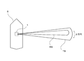
- FIG. 2 is a diagram schematically showing a transmission beam TB formed by the wave transmission unit 2.
- the wave transmitting unit 2 is for transmitting pulsed ultrasonic waves into water, and is installed so that the transmitting surface for transmitting the ultrasonic waves is arranged below the sea surface.
- the wave transmitting unit 2 has one or a plurality of ultrasonic vibrators, and is configured to be capable of forming a three-dimensional transmitted beam TB as shown in FIG.
- the wave transmitting unit 2 is provided on the bottom of the ship so that the central axis Ax of the transmitted beam TB is oblique to the vertical direction (the z-axis direction in FIG. 2). As shown in FIG.
- the shape of the transmission beam TB has a certain thickness (angle ⁇ a) when viewed from the vertical direction, and is formed in a substantially fan shape when viewed from the thickness direction. is there.
- the angle ⁇ a is, for example, 30 degrees, but is not limited to this, and may be a value in the range of, for example, 6 degrees to 90 degrees.
- the angle range (depression angle range) that can be taken in the vertical direction of the substantially fan-shaped transmission beam TB is, for example, a range from 0 degrees (vertically downward) to 90 degrees (horizontal direction).
- the angle range is not limited to this, and the angle range may be a range of 30 degrees to 90 degrees (horizontal direction) or a range of 45 degrees to 90 degrees (horizontal direction).
- the angle range may range from -60 degrees to 60 degrees, which is a range including vertically downward.
- FIG. 3 is a view of the own ship S equipped with the underwater detection device 1 as viewed from above.
- a transmission beam TB formed by the wave transmission unit 2 and a reception beam RB are schematically shown.
- the wave transmitting unit 2 and the receiving unit 3 are driven by the motor 4a (see also FIG. 5).
- the motor 4a rotates the transmitting unit 2 and the receiving unit 3 with the central axis extending in the vertical direction as the center of rotation.
- the transmission beam TB shown in FIG. 3 is rotated in all directions in the horizontal direction centered on the own ship S.
- the motor 4a repeats rotation and stop so that the wave transmitting unit 2 and the receiving unit 3 rotate at a predetermined angle at predetermined time intervals and stop for a predetermined time after the rotation.
- the present invention is not limited to this, and the motor 4a may continuously rotate the transmitting portion 2 and the receiving portion 3.
- the rotation angle detection unit 4b is attached to the motor 4a.
- an encoder is used as the rotation angle detecting unit 4b.
- the present invention is not limited to this, and the signal controlling the rotation of the motor 4a may be analyzed and converted into angle information.
- the number of command pulses input to the stepping motor may be counted and converted into angle information.
- the angle positions of the transmitting unit 2 and the receiving unit 3 in the ⁇ direction are calculated based on the rotation angle of the motor 4a detected by the rotation angle detecting unit 4b.
- the receiving unit 3 is an element that receives the reflected wave including the reflection of the transmitted wave from the underwater target.
- the receiving unit 3 has an ultrasonic vibrator 3a as a plurality of receiving elements.
- the wave receiving unit 3 is provided separately from the wave transmitting unit 2.
- Each ultrasonic vibrator 3a is installed so that the receiving surface 3b that receives ultrasonic waves is arranged below the sea surface. As shown in FIG. 1, the receiving surface 3b of each ultrasonic vibrator 3a is formed in a rectangular shape. Note that FIG. 1 illustrates an embodiment in which the number of ultrasonic vibrators 3a is eight, but the number is not limited to this, and the number of ultrasonic vibrators 3a may be another number. Further, in FIG.
- each ultrasonic transducer 3a receives the reflected wave of each transmission pulse wave, which is an ultrasonic wave transmitted from the transmission unit 2, as a reception wave and converts it into an echo signal as an electric signal.
- These ultrasonic vibrators 3a are arranged in a straight line. That is, the receiving unit 3 is a linear array.
- the angle formed by the horizontal plane and the direction perpendicular to the receiving surface of the linear array on the side where the receiving beam is formed is, for example, 30 degrees (assuming the depression angle direction is positive). However, the angle is not limited to this, and the angle is an angle when the linear array is arranged along the horizontal direction from 0 degree which is an angle when the linear array is arranged along the vertical direction. It may be any other angle within the range up to 90 degrees.
- the wave receiving unit 3 is rotationally driven by the motor 4a.
- the motor 4a rotationally drives the receiving portion 3 with the central axis extending in the vertical direction as the center of rotation. As a result, the receiving portion 3 rotates along the horizontal plane perpendicular to the vertical direction.
- the motor 4a repeats rotation and stop so that the receiving unit 3 rotates by a predetermined angle at predetermined time intervals and stops for a predetermined time after the rotation.
- the present invention is not limited to this, and the motor 4a may continuously rotate the receiving portion 3.
- the motor 4a rotates the transmitting unit 2 and the receiving unit 3 in synchronization with each other. That is, the transmitting unit 2 and the receiving unit 3 cannot move relative to each other.
- the rotation angle detection unit 4b is attached to the motor 4a as described above.
- the angle position of the wave receiving unit 3 in the ⁇ direction is calculated based on the rotation angle of the motor 4a detected by the rotation angle detecting unit 4b.
- the transmission / reception device 5 includes a transmission unit 6 and a reception unit 7.
- the transmission unit 6 amplifies the transmission pulse signal generated by the signal processing unit 10, and applies the amplified signal to the transmission unit 2 as a transmission pulse signal after amplification. As a result, each transmission pulse wave corresponding to each amplified transmission pulse signal is transmitted from the wave transmission unit 2.
- the receiving unit 7 amplifies the echo signal as an electric signal output by the receiving unit 3, and A / D converts the amplified echo signal. After that, the receiving unit 7 outputs the echo signal converted into the digital signal to the signal processing unit 10. More specifically, the receiving unit 7 has a plurality of receiving circuits, and each receiving circuit converts each echo obtained by converting the received wave received by the corresponding ultrasonic vibrator 3a into an electric signal. The above-mentioned predetermined processing is performed on the signal, and each echo signal is output to the signal processing unit 10.
- the signal processing unit 10 generates a transmission pulse signal as a transmission signal and inputs it to the transmission unit 6. Further, the signal processing unit 10 processes the echo signal output from the receiving unit 7 and performs a process of generating image data of the target.
- the signal processing unit 10 includes a hardware processor (for example, CPU (Central Processing Unit), GPU (Graphics Processing Unit), FPGA (field-programmable gate array), etc.), various memories (volatile memory, non-volatile memory), and the like. Equipped with the device.
- CPU Central Processing Unit
- GPU Graphics Processing Unit
- FPGA field-programmable gate array
- various memories volatile memory, non-volatile memory
- various processing units for example, beamforming unit 11, transmission control unit 13, image generation unit 15, etc.
- the beamforming unit (beam forming unit) 11 is a processing unit that executes beamforming processing based on the received signals acquired by the receiving unit 3 and the receiving unit 7.
- the transmission control unit 13 is a processing unit that controls the transmission timing of the transmitted wave by the wave transmission unit 2.
- the transmission control unit 13 controls the operation of transmitting the transmitted wave immediately before the received beamforming with respect to each vertical plane Pi. For example, the transmission control unit 13 transmits the first transmitted wave in the vertical plane P1 (see FIG. 10) before the first beamforming is performed, and in the vertical plane P2 (see FIG. 12).
- the transmission timing of the transmitted wave is controlled by the wave transmitting unit 2 so that the second transmitted wave is transmitted before the first beamforming is performed.
- the image generation unit 15 is a processing unit that generates various image data (D1, D2, etc.) based on the processing result of the beamforming process.
- the display unit 8 displays an image corresponding to the image data output from the signal processing unit 10 on the display screen.
- the display unit 8 displays two types of detection images M1 and M2 side by side in the left-right direction.
- one detection image M1 is a three-dimensional detection image.
- the other detection image M2 is a two-dimensional detection image (PPI (Plan Position Indicator) type detection image).
- PPI Plan Position Indicator
- these two detection images M1 and M2 are arranged and displayed in parallel in the display screen of the display unit 8. Specifically, as shown in FIG. 9, an image 210 in which the detected images M1 and M2 are arranged in the left-right direction and combined is displayed. Note that FIG. 10 is a diagram showing only the detection image M1 taken out, and FIG. 11 is a diagram showing only the detection image M2 taken out.
- the three-dimensional detection image M1 (see FIGS. 9 and 10) is a screen that displays the underwater state below the ship in three dimensions as a bird's-eye view.
- the user can check the underwater condition (for example, single fish and school of fish, undulations of the seabed, presence / absence and position of structures such as artificial reefs) below the ship S. It can be grasped three-dimensionally.
- the surface F1 represents the seabed.
- the portion 51 with sandy hatching and diagonal hatching represents a school of fish.
- the two-dimensional detection image M2 is a screen that displays the distance and the direction radially (so to speak, two-dimensionally) around the own ship S.
- the two-dimensional detection image M2 specifically, M21
- the underwater state in the specific depression angle (tilt angle) ⁇ s (see FIG. 8) direction from the own ship S over the omnidirectional angle ⁇ is displayed two-dimensionally. Will be done.
- the two-dimensional detection image M2 is also referred to as a PPI (Plan Position Indicator) type detection image.
- color-coded display is performed according to the echo signal intensity.
- the high echo intensity area is shown in red
- the medium echo intensity area is shown in green
- the low echo intensity area is shown in blue.
- the high echo intensity area is provided with dark hatching
- the medium echo intensity area is provided with light dot hatching
- the low echo intensity area is provided with even lighter dots. It has hatching. According to such a display, the user can determine the intensity of the reflected wave from the target and grasp the density of the target (fish school or the like).
- Each detection image M1 and M2 is generated based on the beamforming data acquired by beamforming.
- beamforming is a signal processing technique for controlling the directivity (selectivity with respect to direction) of the receiving unit 3. Signals whose phase and amplitude are controlled by delays and filters interfere with each other to emphasize or reduce signals from a specific direction.
- the three-dimensional detected image M1 is displayed based on the image data D1.
- the image data D1 is generated based on the first beamforming data acquired by the first beamforming (here, adaptive beamforming).
- the first beamforming is executed in each of a plurality of tilt directions (depression directions) in each vertical plane Pi.
- FIG. 7 it is a concept that the first beamforming is executed in each of a plurality of tilt directions (tilt angle ⁇ (depression angle) direction) ( ⁇ 1, ⁇ 2, ⁇ 3, ...) In a certain vertical plane Pi. Is shown.
- the process (process of executing the first beamforming in a plurality of tilting directions within each vertical plane Pi) is executed for each of the plurality of vertical planes Pi. More specifically, the process is executed for a plurality of vertical planes Pi (at least two vertical planes) whose azimuths are changed for each angle ⁇ (see FIG. 4).
- the plurality of vertical planes Pi are a plurality of vertical planes corresponding to different azimuth angles ⁇ , and at least two vertical planes (P1, P2, etc.) are not parallel to each other (angles oblique to each other (angles oblique to each other). A plane with an angle other than zero degrees). It is preferable that the process is performed on a larger number of vertical planes.
- the three-dimensional detection image M1 is preferably generated by using beamforming having a high angular resolution ⁇ (see FIG. 7) in the depression angle (tilt angle) ⁇ direction.
- FIG. 7 is a diagram showing how the first beamforming is performed in a plurality of tilting directions.
- the angular resolution ⁇ in the depression angle (tilt angle) ⁇ direction is relatively high (value ⁇ is small) (fine), the surface shape of the seabed or the like should be expressed relatively sharply (sharply). Is possible.
- the beamforming having high angular resolution in the depression angle (tilt angle) ⁇ direction for example, adaptive beamforming (Capon method, MUSIC method, etc.) is preferably used.
- the two-dimensional detection image M2 is displayed based on the image data D2.
- the image data D2 is generated based on the second beamforming data acquired by the second beamforming (here, delayed sum beamforming).
- the second beamforming is executed in one inclination direction (specific tilt angle ⁇ s (depression angle) direction) in each vertical plane Pi.
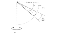
- FIG. 8 is a diagram showing how the second beamforming is performed in one inclination direction.
- FIG. 8 conceptually shows how the second beamforming is performed in one tilt direction (specific tilt angle ⁇ s (depression angle) direction) in a certain vertical plane Pi.
- the process (process of executing the second beamforming in one inclination direction in each vertical plane Pi) is executed for each of the plurality of vertical planes Pi. More specifically, the process is executed for a plurality of vertical planes Pi (at least two vertical planes) whose azimuths are changed for each angle ⁇ (see FIG. 4).
- the plurality of vertical planes are a plurality of vertical planes corresponding to different azimuth angles, and at least two of them are a plurality of two vertical planes that are not parallel to each other. It is preferable that the process is performed on a larger number of vertical planes.
- the two-dimensional detection image M2 is a display image used by many users of conventional underwater detection devices. By visually recognizing the (familiar) two-dimensional detection image M2, the user can appropriately recognize the existence position (distance and direction) of the school of fish in the specific tilt angle ⁇ s direction.
- beamforming in which the echo intensity changes smoothly, for example, delayed sum beamforming (beamforming that delays and adds) in order to grasp the density of the school of fish. ..
- FIG. 6 is a flowchart showing the operation of the underwater detection device 1.
- the transmitting unit 2 and the receiving unit 3 are driven by the motor and rotate around the vertical axis, the processes related to the plurality of vertical planes Pi are sequentially executed. Specifically, as described above, the motor 4a rotates and stops so that the transmitting unit 2 and the receiving unit 3 rotate at a predetermined angle at predetermined time intervals and stop for a predetermined time after the rotation. And repeat.
- processing related to the vertical plane P1 having an azimuth angle of ⁇ 1 is executed (steps S11 to S13).
- the beamforming data is generated by performing the wave transmitting process and the wave receiving process using the transmitting unit 2 and the receiving unit 3 and the like (step S11).
- ultrasonic waves are transmitted into the water from the transmitting unit 2, and the receiving unit 3 facing the azimuth ⁇ 1.
- the received wave is received by the receiving surface 3b.
- the first and second beamforming are performed in the vertical plane P1 (see FIG. 10) existing along the azimuth angle ⁇ 1.
- the transmission timing of such a transmission wave is controlled by the transmission / reception device 5 and the signal processing unit 10.
- a process of forming a so-called received beam is executed.
- the first beamforming for generating the detected image M1 is executed in a plurality of depression angles ⁇ ( ⁇ 1, ⁇ 2, ⁇ 3, ...)
- the second beamforming for generating the detected image M2 is performed. Is executed in the direction of one depression angle ⁇ s.
- the first beamforming executed in the vertical plane P1 along the azimuth angle ⁇ 1 and the second beamforming executed in the vertical plane are based on the received signals obtained from the same transmitted wave. Will be executed. In this way, two types of beamforming (for generating the detected images M1 and M2) are executed in the vertical plane P1 in the azimuth angle ⁇ 1 direction.
- the detection images M1 and M2 are generated (updated) based on the processing results of the two types of beamforming processing (step S12). Specifically, in each of the detected images M1 and M2, the image of the portion where the latest echo information is obtained by the beamforming process in the specific azimuth angle ⁇ 1 direction is updated.
- the portion has a substantially fan-shaped cross section (received beam RB in FIG. 3) having a linear direction extending from the own ship S toward a specific azimuth angle ⁇ 1 as a radial direction and a central angle ⁇ in the azimuth direction ( ⁇ direction).
- the image 210 including the updated detection images M1 and M2 is displayed on the display unit 8 (step S13). Specifically, the detection image M1 is displayed based on the processing result of the first beamforming and the like, and the detection image M2 is displayed based on the processing result and the like of the second beamforming (see FIG. 9).
- the vertical plane (vertical cross section) P1 to be processed by the beamforming process and the drawing update process is drawn.
- the vertical plane P1 is drawn as, for example, a translucent thin plate upper part.
- the boundary line 69 is a line of intersection between the seabed F1 and the vertical plane Pi (P1, etc.).
- the vertical plane P1 to be processed is drawn (in other words, the display portion (vertical plane P1) indicating the direction ( ⁇ 1) in which the receiving portion 3 in the first beamforming is facing is in the first image data D1. According to (generated), it is possible to easily grasp the direction in which the receiving unit 3 is facing at that time. That is, the user can easily know the vertical plane P1 that is currently being processed for beamforming processing and the like.
- the three-dimensional detection image M1 has one tilt direction (tilt angle) in the second beamforming executed for the generation of the two-dimensional detection image M2. ⁇ s) is shown.
- the image generation unit 15 is a display portion 61 indicating one specific inclination direction in the second beamforming in the vertical plane P1 (specifically, the depression angle ⁇ s from directly below the own ship S toward the outer peripheral side). A line segment inclined downward) is added to the first image data D1. Then, a three-dimensional detection image M1 (see FIGS. 9 and 10) is displayed based on the first image data D1.
- the display portion (also referred to as a display part) 61 is not limited to a linear shape (line segment shape), and as shown in FIG. 8, expands ( ⁇ ) in the depression angle direction around one specific inclination direction ⁇ s. It may have a shape (specifically, an elongated substantially fan shape). According to this, the user can grasp the directivity characteristic of the second beamforming (search range by the second beamforming) more clearly (including the degree of expansion in the depression angle direction).
- the wave transmitting unit 2 and the receiving unit 3 rotate by a predetermined angle ⁇ around the vertical axis by the motor drive.
- the beam forming at the time of execution
- the transmitting unit 2 and the receiving unit 3 rotate around the vertical axis by being driven by the motor 4a (driving unit).
- step S11 to S13 the processing related to the vertical plane P2 having the azimuth angle ⁇ 2 is executed (steps S11 to S13).
- the received wave is received by the receiving surface 3b of the receiving portion 3.
- the first and second beamforming are performed in the vertical plane P2 existing along the azimuth angle ⁇ 2. More specifically, the first beamforming for generating the detected image M1 is executed in a plurality of depression angles ⁇ ( ⁇ 1, ⁇ 2, ⁇ 3, ...), And the second beam for generating the detected image M2 is executed. Forming is performed in the direction of one depression angle ⁇ s. In this way, two types of beamforming (for generating the detected images M1 and M2) are executed in the vertical plane P2 in the azimuth angle ⁇ 2 direction (step S11).
- the detection images M1 and M2 are updated based on the processing results of the two types of beamforming processing (step S12), and the image 210 including the updated detection images M1 and M2 is displayed on the display unit 8 (step S13). ..
- the detection image M1 shows one tilt direction (tilt angle ⁇ s) in the second beamforming executed for generating the two-dimensional detection image M2.
- a display portion 61 indicating one specific inclination direction in the second beamforming in the vertical plane P2 (specifically, a line segment inclined downward by a depression angle ⁇ s from directly below the own ship S toward the outer peripheral side). ) Is displayed in the three-dimensional detection image M1.
- the predetermined angle ⁇ is about 30 degrees is shown, but the present invention is not limited to this, and the predetermined angle ⁇ is another value (smaller value or larger value). ) May be.
- the wave transmitting unit 2 and the receiving unit 3 rotate again by a predetermined angle ⁇ around the vertical axis by the motor drive.
- ⁇ T time interval
- the wave transmitting unit 2 and the receiving unit 3 rotate again by a predetermined angle ⁇ around the vertical axis by the motor drive.
- the transmitting unit 2 and the receiving unit 3 rotate around the vertical axis by being driven by the motor 4a.
- step S11 to S13 relating to the vertical plane P3 (FIG. 13) having an azimuth angle of ⁇ 3 are executed.
- the received wave is received by the receiving surface 3b of the wave unit 3, and two types of beamforming (for generating the detected images M1 and M2) are executed in the vertical plane P3 in the azimuth angle ⁇ 3 direction.
- the detection images M1 and M2 are updated based on the processing results of the two types of beamforming processing (step S12), and the image (composite image) 210 including the updated detection images M1 and M2 is displayed on the display unit 8. (Step S13).
- the vertical plane P3 to be processed by the beamforming process and the drawing update process is drawn. Further, a display portion 61 (specifically, a line segment inclined downward by a depression angle ⁇ s from directly below the own ship S toward the outer peripheral side) indicating one specific inclination direction in the second beam forming in the vertical plane P3 is provided. It is displayed on the three-dimensional detection image M1.
- step S11 to S13 the processes related to the corresponding vertical plane Pi (steps S11 to S13) are executed for the plurality of azimuth angles ⁇ i over all directions.
- the inclination direction ⁇ s in the above embodiment can be changed by the user. Specifically, the user sets one tilt direction ⁇ s in the second beamforming for generating the two-dimensional detection image M2 to a predetermined user interface (setting screen (not shown) displayed on the display unit 8 or the like). It is possible to change the setting using. For example, by inputting a new tilt angle ⁇ s (for example, “30 degrees”) after changing the setting numerically (input as a digital value), the new tilt angle direction is set to a predetermined angle (for example, 1 degree). It can be changed in increments.
- a new tilt angle ⁇ s for example, “30 degrees”
- a predetermined angle for example, 1 degree
- the user sets the one inclination direction ⁇ s independently of the plurality of inclination directions ⁇ ( ⁇ 1, ⁇ 2, ⁇ 3, ...) In the first beamforming for generating the three-dimensional detection image M1. It is possible to do. Specifically, the user can change only the one inclination direction ⁇ s without changing the plurality of inclination directions ⁇ ( ⁇ 1, ⁇ 2, ⁇ 3, ).
- the image data D1 is data generated based on the first beamforming data acquired by the first beamforming (here, adaptive beamforming).
- the first beam forming is performed in a plurality of tilt directions (tilt angle ⁇ direction) in at least two vertical planes Pi (for example, in the vertical plane P1 and in the vertical plane P2) that are not parallel to each other (corresponding to different azimuth angles). (Depression direction)) is the received beam forming process executed.
- the image data D2 is data generated based on the second beamforming data acquired by the second beamforming (here, delayed sum beamforming).
- the second beam forming is one specific tilt direction (eg, tilt angle) in each of at least two non-parallel vertical planes Pi (eg, in the vertical plane P1 and in the vertical plane P2) (corresponding to different azimuth angles). It is a received beam forming process executed in the ⁇ s direction.
- the advantages obtained with the PPI display image (two-dimensional detection image) M2 may not be obtained. More specifically, since it is difficult to specify the specific depression angle direction, what kind of depression angle direction (tilt angle) the target such as a school of fish exists, and how far the target is from the ship's position. There is a problem that it is not always easy to grasp whether it exists at the position.
- the PPI display image M2 it is easy to grasp the state of the target (fish school, etc.) with respect to the designated specific depression angle direction. Specifically, it is relatively easy to grasp in what depression angle direction (tilt angle) the target is located and how far the target is from the ship's position. ..
- the user can grasp desired information by appropriately using these images M1 and M2.
- the first beamforming and the second beamforming are different processes from each other. Specifically, adaptive beamforming is executed as the first beamforming, and delayed sum beamforming is executed as the second beamforming.
- delayed sum beamforming is used to generate a PPI display image (two-dimensional detection image), in which the echo intensity changes smoothly and responds linearly to the target. Therefore, it is possible to acquire an image that more appropriately reflects the density of the school of fish. More specifically, the difference in echo intensity for each school of fish is expressed as a difference in color level, so that the user can easily determine the density of each school of fish.
- adaptive beamforming with high resolution in the vertical direction is used to generate a three-dimensional display image (three-dimensional detection image).
- the received beam formed in at least one of a plurality of tilt directions in the first beamforming is the second beamforming (here, delayed sum beamforming). It has higher resolution in the depression angle direction (tilt angle ⁇ direction) than the received beam formed in one specific tilt direction.
- the resolution ⁇ by the first beamforming has a smaller value (that is, higher resolution) than the resolution ⁇ by the second beamforming (see FIG. 8). Therefore, it is possible to grasp the surface shape of the object in each vertical cross section Pi relatively accurately.
- adaptive beamforming with high resolution in the depression angle direction is used to generate the image for 3D display, so that the undulating shape of the seabed and the shape of the school of fish can be displayed as a relatively sharp image. It is possible to get it.
- the detection images M1 and M2 are updated and displayed each time the beamforming process and the image data generation process for each of the plurality of vertical planes Pi are completed.
- the detection images M1 and M2 are gradually updated every predetermined angle ⁇ .
- the update display of the detected images M1 and M2 may be performed every time all the processes relating to the plurality of vertical planes in all directions are completed.
- the detection images M1 and M2 for all directions may be updated at once.
- the vertical plane Pi in the detection image M1 may be displayed asynchronously with the processing timing.
- a vertical plane Pi extending in the direction of the azimuth angle ⁇ specified by the user may be displayed according to the operation of the user or the like.
- the mechanical scanning type sonar is exemplified as the underwater detection device 1, but the present invention is not limited to this.
- the underwater detector 1 may be a scanning sonar.
- a wave transmitting / receiving unit (also referred to as a transmitter / receiver) is configured by integrating the transmitting unit 2 and the receiving unit 3. ) 20 is provided.
- the transmitting / receiving unit 20 has a plurality of receiving elements 33a arranged in two dimensions.
- a substantially cylindrical wave transmitting / receiving unit 20 is illustrated.
- the wave transmitting / receiving unit 20 of FIG. 17 has a substantially cylindrical housing and ultrasonic vibrators 33a as a plurality of transmitting / receiving elements attached to the outer peripheral surface of the housing.
- the ultrasonic vibrator 33a transmits ultrasonic waves into water, receives echoes, converts the echoes into electrical signals (received signals), and outputs the echoes to the receiving unit 7.
- a transmitting / receiving unit 20 (also referred to as 20A) having a substantially cylindrical shape is exemplified, but the present invention is not limited to this, and the transmitting / receiving unit 20 has another shape (see FIGS. 18 to 20).
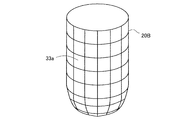
- the transmission / reception unit 20 (20B) shown in FIG. 18 may be used
- the transmission / reception unit 20 (20C) shown in FIG. 19 may be used
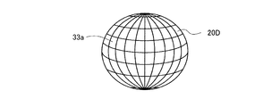
- the transmission / reception unit 20 (20D) shown in FIG. 20 may be used.
- the wave transmitting / receiving portion 20B (FIG. 18) has a housing formed in a substantially cylindrical shape and a hemispherical lower portion.
- a plurality of ultrasonic vibrators 33a are attached to the outer peripheral surface of the cylinder and the hemisphere of the housing.
- the wave transmitting / receiving unit 20C (FIG. 19) has a housing formed in a downward hemisphere.
- a plurality of ultrasonic vibrators 33a are attached to the hemisphere of the housing.
- the wave transmitting / receiving unit 20D (FIG. 20) has a spherical housing.
- a plurality of ultrasonic vibrators 33a are attached to the entire surface of the housing.
- the transmission / reception unit 20 transmits the transmission wave in all directions in the horizontal direction centered on the own ship S. Further, the transmission / reception unit 20 is driven by the transmission / reception device 5 to transmit the transmission wave, and generates a reception signal based on the reflected wave including the reflection of the transmission wave from the underwater target such as the fish school 51 and the seabed F1.
- the beamforming unit 11 performs beamforming processing (first beamforming and second beamforming) on complex signals obtained from a plurality of specific ultrasonic transducers 33a (at least a part of the ultrasonic transducers 33a). As a result, the beamforming unit 11 generates a received beam signal which is a signal equivalent to that obtained by a single ultrasonic oscillator having a sharp directivity in a specific direction. The region where this beam signal is formed is also referred to as a reception beam region. The beamforming unit 11 repeatedly performs this process while changing the combination of the ultrasonic transducers 33a to be subjected to the beam forming process, thereby generating a large number of received beam signals having directivity in each direction.
- beamforming processing first beamforming and second beamforming
- the beamforming unit 11 receives from a group of elements (for example, two or more receiving elements facing the azimuth ⁇ 1 direction) related to the first combination of a plurality of receiving elements (ultrasonic transducers 33a). Based on the signal, the first beamforming and the second beamforming in the first vertical plane P1 of the plurality of vertical planes are executed. Further, the beamforming unit 11 is from an element group (for example, two or more receiving elements facing the azimuth ⁇ 2 direction) related to a second combination different from the first combination among the plurality of receiving elements. Based on the received signal, the first beamforming and the second beamforming in the second vertical plane P2 of the plurality of vertical planes are executed. The same applies to the other vertical planes among the plurality of vertical planes.
- a group of elements for example, two or more receiving elements facing the azimuth ⁇ 1 direction
- the beamforming unit 11 is from an element group (for example, two or more receiving elements facing the azimuth ⁇ 2 direction) related to a second combination different from the first
- the beamforming unit 11 In the first beamforming, the beamforming unit 11 generates a received beam signal having a beam width narrower than the beam width of the transmitted wave in the depression angle direction, and the transmitted wave is transmitted by gradually changing the tilt angle thereof. Scan the area. In this way, the beamforming unit 11 executes the first beamforming (adaptive beamforming) in a plurality of inclination directions (depression angle directions) in each vertical plane Pi.
- the position information of each three-dimensional data (detailed later) generated based on these received beam signals is reflected from the transmitting / receiving unit 20 obtained from the time from the transmission of the transmitted wave to the reception. It is calculated based on the distance to the target and the direction of the received beam signal.
- the beamforming unit 11 executes the first beamforming (adaptive beamforming) in a plurality of inclination directions ⁇ i (depression angle directions) in each vertical plane Pi, and based on the amplitude of the received beam signal and the like, the first beam. Get forming data.
- the image generation unit 15 generates three-dimensional data showing the distribution of the underwater targets around the ship based on the first beamforming data. Further, the image generation unit 15 generates 3D image data D1 for displaying the 3D detection image M1 by projecting the 3D data on a 2D plane (display surface).
- the beamforming unit 11 executes the second beamforming (delayed sum beamforming) in one inclination direction ⁇ s (depression angle direction) in each vertical plane Pi, and is based on the amplitude of the received beam signal and the like. Acquire the second beamforming data.
- the image generation unit 15 generates image data D2 (image data for PPI display) showing the distribution of the underwater target in one inclination direction ⁇ s around the ship based on the second beamforming data.
- the beamforming unit 11 performs first beamforming (adaptive beamforming) in a plurality of inclination directions (depression angle directions) in each of a plurality of vertical planes Pi that are not parallel to each other (corresponding to different azimuth angles). Is executed to acquire the first beamforming data. Further, the image generation unit 15 generates the first image data D1 (display data of the detected image M1) based on the first beamforming data. Then, the detection image M1 based on the first image data D1 is displayed on the display unit 8.
- the beamforming unit 11 executes the second beamforming (delayed sum beamforming) in one inclination direction (depression angle direction) in each of the plurality of vertical planes Pi, and acquires the second beamforming data. .. Further, the image generation unit 15 generates the second image data D2 (display data of the detected image M2) based on the second beamforming data. Then, the detection image M2 based on the second image data D2 is displayed on the display unit 8.
- the third embodiment is a modification of the first and second embodiments. Hereinafter, the differences from the first embodiment and the like will be mainly described.
- FIG. 14 is a diagram showing a display screen according to the third embodiment.
- a two-dimensional PPI display (detection image M22) relating to the tilt angle ⁇ u different from the tilt angle ⁇ s is further added.
- the third beamforming is beamforming at one tilt angle ⁇ u.
- the third beamforming for example, beamforming (delay sum beamforming) of the same method as the second beamforming may be executed.
- the third beamforming data acquired by the third beamforming performed in the tilt angle ⁇ u direction is generated, and the third image data D3 is generated based on the third beamforming data.
- the two-dimensional PPI display image (detection image) M22 relating to the tilt angle ⁇ u is further displayed.
- the two-dimensional PPI display image (detection image) M21 relating to the tilt angle ⁇ s is also displayed (see FIG. 14). According to this, since the two-dimensional PPI display images (detection images) M21 and M22 relating to the two tilt angles ⁇ s and ⁇ u are displayed in parallel at the same time, the user can use the two types of depression angle directions ( ⁇ s direction and ⁇ u direction). It is possible to grasp the state of water at the same time.
- a display portion (line segment) 61 indicating one specific tilt direction (tilt angle ⁇ s) on a certain vertical plane Pi is displayed, and the specific tilt on the vertical plane Pi is displayed.
- a display portion (line segment) 62 indicating the direction (tilt angle ⁇ u) is also displayed.
- the two tilt angles ⁇ s and ⁇ u are shown by using the numerical values in the two-dimensional PPI display images (detection images) M21 and M22 in addition to the display portions 61 and 62 in the three-dimensional detection image M1.
- two images M41 and M42 (sub-images showing tilt angles ⁇ s, ⁇ u, etc.) as shown in FIG. 15 may be additionally displayed in the image 210.
- the images M41 and M42 are diagrams showing the state in the cut plane obtained by cutting the three-dimensional detection image M1 on a certain vertical plane Pi (a vertical plane along a certain azimuth angle ⁇ i), respectively.
- the image M41 is an image showing echo information in the vertical plane Pi and an image showing a tilt angle ⁇ s or the like with respect to the image M21.
- the set tilt angle ⁇ s direction is indicated by a straight line (line segment) 71.
- the image M42 is an image showing echo information in the vertical plane Pi and an image showing a tilt angle ⁇ u or the like with respect to the image M22.
- the set tilt angle ⁇ u direction is indicated by a straight line (line segment) 72.
- the image M5 as shown in FIG. 16 may be further added in the image 210.
- the image M5 is an image similar to the conventional fishfinder image.
- the echo information may be acquired by using either the first beamforming or the second beamforming.
- the first beamforming and the second beamforming are different processes (specifically, different methods of processing), but the first beamforming and the second beamforming are not limited thereto.
- the two-beamforming may be the same method of processing (adaptive beamforming, etc.).
- the received beam formed by the second beam forming (delayed sum beam forming) in one specific inclination direction in each of the plurality of vertical planes is the one in each vertical plane. It has a shape that is symmetric with respect to a specific inclination direction (a shape that is axisymmetric with respect to the straight line extending in the specific direction).
- Such beamforming is executed by using, for example, the Chebyshev window as a window for amplitude window processing in signal processing using a complex function. Further, according to the delayed sum beamforming using the Chebyshev window, it is possible to make the beam width in the depression angle direction relatively narrow in the delayed sum beamforming. Therefore, in the two-dimensional PPI display, it is possible to express the edge of the seabed ring relatively sharply.
- the present invention is not limited to this, and another window for amplitude window processing may be used in the second beamforming.
- the SINC function may be used as a window for amplitude window processing.
- the delayed sum beamforming using the SINC function it is possible to make the beam width in the depression angle direction relatively wide. Therefore, in the two-dimensional PPI display, it is possible to grasp the existence of a wreck sinking on a flat seabed relatively clearly. Specifically, the user can relatively clearly grasp the existence of a wreck sinking on a flat seabed by visually recognizing a wide range of echo images including a part corresponding to the wreck and a part corresponding to the shadow of the wreck. It is possible.
- a window that forms a desired amplitude shape may be used.
- a beam formed in one specific inclination direction in each of a plurality of vertical planes Pi has an asymmetric shape with respect to the one specific inclination direction (a shape that is not axisymmetric with respect to a straight line extending in the one specific direction). It may be a beam to have. More specifically, the reception beam similar to the cosecant square beam (the signal strength in the depression angle direction (tilt angle 90 degrees direction) on the side closer to the vertical lower side is reduced and the depression angle direction on the side closer to the horizontal direction (sea surface direction)).
- a window may be used to generate (a received beam that increases the signal strength in the direction of the tilt angle of 0 degrees).
- the echo levels of the flat seafloor are almost equal regardless of the depression angle, so that the height of the flat seafloor and the structure (seafloor structure) protruding from the seafloor is high. The difference becomes clear. Therefore, the user can detect the submarine structure relatively easily.
- the display unit 8 may alternately display two types of detection images M1 and M2.
- the detection image M1 an image displayed from a bird's-eye view from diagonally above is exemplified, but the present invention is not limited to this, and an image viewed from directly above (an image based on the first beamforming). May be displayed as the detection image M1.
- All processes described herein can be embodied and fully automated by software code modules executed by a computing system that includes one or more computers or processors.
- the code module can be stored on any type of non-transitory computer-readable medium or other computer storage device. Some or all methods may be embodied in dedicated computer hardware.
- any particular action, event, or function of any of the algorithms described herein may be performed in different sequences and may be added, merged, or excluded altogether. (For example, not all described actions or events are required to execute the algorithm). Further, in certain embodiments, operations or events are performed in parallel rather than sequentially, for example through multithreading, interrupt handling, or through multiple processors or processor cores, or on other parallel architectures. Can be done. In addition, different tasks or processes can be performed by different machines and / or computing systems that can work together.
- the various exemplary logical blocks and modules described in connection with the embodiments disclosed herein can be implemented or executed by a machine such as a processor.
- the processor may be a microprocessor, but instead, the processor may be a controller, a microcontroller, or a state machine, or a combination thereof.
- the processor can include an electrical circuit configured to process computer executable instructions.
- the processor includes an application specific integrated circuit (ASIC), a field programmable gate array (FPGA), or other programmable device that performs logical operations without processing computer executable instructions.
- ASIC application specific integrated circuit
- FPGA field programmable gate array
- Processors can also be a combination of computing devices, such as a combination of a digital signal processor (digital signal processor) and a microprocessor, multiple microprocessors, one or more microprocessors in combination with a DSP core, or any other of that. It can be implemented as such a configuration. Although described primarily with respect to digital technology herein, the processor may also include primarily analog devices. For example, some or all of the signal processing algorithms described herein can be implemented by analog circuits or mixed analog and digital circuits. Computing environments include, but are not limited to, any type of computer system that is based on a microprocessor, mainframe computer, digital signal processor, portable computing device, device controller, or computing engine within the device. be able to.
- conditional languages such as “can,” “can,” “will,” or “may” include other features, elements, and / or steps in a particular embodiment. Embodiments are understood in the context commonly used to convey that they do not include. Thus, such conditional languages are generally any method in which features, elements and / or steps are required for one or more embodiments, or one or more embodiments are these features. It does not mean that the elements and / or steps are included in any particular embodiment or necessarily include logic to determine whether they are performed.
- Disjunctive languages such as the phrase "at least one of X, Y, Z" have items, terms, etc. of X, Y, Z, or any combination thereof, unless otherwise stated. It is understood in the context commonly used to indicate that it can be (eg X, Y, Z). Thus, such a disjunctive language generally requires at least one of X, at least one of Y, or at least one of Z, each of which has a particular embodiment. Does not mean.
- a numeral such as “one” should generally be construed as containing one or more described items.
- terms such as “one device configured to” are intended to include one or more listed devices.
- One or more of such enumerated devices can also be collectively configured to perform the described citations.
- processors configured to run A, B, and C below are a first processor configured to run A and a second processor configured to run B and C.
- processors with are typically at least the enumerated number (eg, other modifiers).
- a mere enumeration of "two enumerations” without the use should be interpreted to mean at least two enumerations, or two or more enumerations).
- the terms used herein should generally be construed as “non-limiting” terms (eg, the term “including” should be construed as “not only that, but at least including” and “...
- the term “has” should be interpreted as “having at least”, and the term “including” should be interpreted as “including, but not limited to,”). Those skilled in the art will judge that this is the case.
- the term “horizontal” as used herein refers to a plane or plane parallel to the floor or surface of the area in which the system being described is used, regardless of its orientation. The method to be done is defined as the plane on which it is carried out.
- the term “floor” can be replaced with the term “ground” or “water surface”.
- the term “vertical / vertical” refers to the direction perpendicular / vertical to the defined horizon. Terms such as “upper”, “lower”, “lower”, “upper”, “side”, “higher”, “lower”, “upper”, “beyond”, and “lower” are defined for the horizontal plane. ing.
- connection means removable, movable, fixed, adjustable, unless otherwise noted. And / or should be construed as including removable connections or connections. Connections / connections include direct connections and / or connections with intermediate structures between the two components described.
- the numbers preceded by terms such as “approximately,” “about,” and “substantially” as used herein include the enumerated numbers, and further. Represents an amount close to the stated amount that performs the desired function or achieves the desired result. For example, “approximately,” “about,” and “substantially” mean values less than 10% of the stated values, unless otherwise stated.
- features of embodiments in which terms such as “approximately,” “about,” and “substantially” are previously disclosed perform further desired functions. Or represents a feature that has some variability to achieve the desired result for that feature.
Landscapes
- Engineering & Computer Science (AREA)
- Computer Networks & Wireless Communication (AREA)
- Physics & Mathematics (AREA)
- General Physics & Mathematics (AREA)
- Radar, Positioning & Navigation (AREA)
- Remote Sensing (AREA)
- Measurement Of Velocity Or Position Using Acoustic Or Ultrasonic Waves (AREA)
Abstract
【課題】より見易い表示を実現することが可能な水中探知装置およびそれに関連する技術を提供する。 【解決手段】水中探知装置のビームフォーミング部は、少なくとも2つの鉛直平面Pi(P1,...等)内のそれぞれにおける複数の傾斜方向(俯角方向)にて、第1ビームフォーミング(適応ビームフォーミング等)を実行し、当該少なくとも2つの鉛直平面Pi内のそれぞれにおける一の特定傾斜方向にて、第2ビームフォーミング(遅延和ビームフォーミング等)を実行する。画像生成部は、第1ビームフォーミングによって取得された第1ビームフォーミングデータに基づいて第1画像データ(探知画像M1の表示用データ)を生成し、第2ビームフォーミングによって取得された第2ビームフォーミングデータに基づいて第2画像データ(探知画像M2の表示用データ)を生成する。
Description
本発明は、水中探知装置およびそれに関連する技術に関する。
水中環境内における物体を探知するとともに、その探知結果に基づく画像データを生成する技術が存在する。
具体的には、2次元的な表示技術(いわゆるPPI(Plan Position Indicator)表示技術)が存在する。詳細には、互いに平行でない複数の鉛直平面内のそれぞれにおける一の特定俯角方向にて受信信号に基づくビームフォーミング(遅延和ビームフォーミング等)が実行され、当該ビームフォーミングの処理結果に基づく画像が表示される。
一方、本願出願人は、いわゆる3次元表示技術をも案出している。たとえば、互いに平行でない複数の鉛直平面内のそれぞれにおける複数の俯角方向にて受信信号に基づくビームフォーミングが実行され、当該ビームフォーミングの処理結果に基づく画像(詳細には、1種類の画像(3次元探知画像)のみ)を表示する技術を案出している。
なお、特許文献1においては、複数のチルト角(俯角)の方向のそれぞれにおけるビームフォーミングの結果が互いに色で区別されつつ表示画面内に合成表示される技術も開示されている(特許文献1の第2図等参照)。このような技術は、複数の俯角方向におけるビームフォーミングの結果を用いた探知画像が表示されていることから、一種の3次元探知情報の表示技術(3次元表示技術)であると言えるものの、当該探知画像(1種類の画像)のみが表示される技術に過ぎない。
しかしながら、PPI表示画像と3次元表示画像とのうちいずれか1種類の画像のみが表示される場合、次のような問題が存在する。
たとえば、3次元表示のみが行われる場合、PPI表示(2次元表示)で得られていた利点が得られないことがある。より詳細には、特定俯角方向の指定等が困難であるため、魚群等の物標がどのような俯角方向(チルト角度)に存在するのか、および当該物標が自船位置からどの程度離れた位置に存在するのかを把握することが必ずしも容易でない、などの問題が存在する。
逆に、PPI表示のみが行われる場合、3次元表示で得られていた利点が得られない。具体的には、海底の形状および/または魚群の形状等を把握することが困難である。
このように、PPI表示画像と3次元表示画像とのうちいずれか1種類の画像のみが表示される場合には、必ずしも見易い表示がなされるとは言えない、との問題が存在する。
そこで、この発明は、より見易い表示を実現することが可能な水中探知装置およびそれに関連する技術を提供することを課題とする。
(1)上記課題を解決すべく、本発明の或る局面に係る水中探知装置は、送信波を送信する送波部と、水中ターゲットからの前記送信波の反射を含む反射波に基づいて受信信号を生成する複数の受信素子、を有する受波部と、前記受信信号に基づきビームフォーミング処理を実行するビームフォーミング部と、前記ビームフォーミング処理の処理結果に基づき第1画像データと第2画像データとを生成する画像生成部と、を備え、前記ビームフォーミング部は、少なくとも第1鉛直平面内と第2鉛直平面内とにおいて、複数の傾斜方向における第1ビームフォーミングを前記受信信号に基づいて実行し、少なくとも前記第1鉛直平面内と前記第2鉛直平面内とにおいて、一の特定傾斜方向における第2ビームフォーミングを前記受信信号に基づいて実行し、前記第1鉛直平面と前記第2鉛直平面とは、互いに平行ではなく、前記画像生成部は、前記第1ビームフォーミングによって取得される第1ビームフォーミングデータに基づいて、前記第1画像データを生成し、前記第2ビームフォーミングによって取得される第2ビームフォーミングデータに基づいて、前記第2画像データを生成する。
(2)前記第1ビームフォーミングと前記第2ビームフォーミングとは互いに異なる処理である場合がある。
(3)前記第1ビームフォーミングによって前記複数の傾斜方向のうち少なくとも1つの方向に形成される受信ビームは、前記第2ビームフォーミングによって前記一の特定傾斜方向に形成される受信ビームよりも、鉛直方向に高い分解能を有する、場合がある。
(4)前記第1ビームフォーミングは、適応ビームフォーミングであり、前記第2ビームフォーミングは、遅延和ビームフォーミングである、場合がある。
(5)前記画像生成部は、前記第2ビームフォーミングにおける前記一の特定傾斜方向を示す表示部分を前記第1画像データ内に追加する、場合がある。
(6)前記水中探知装置は、前記受波部を回転させる駆動部、をさらに備え、前記駆動部は、前記第1鉛直平面内における前記第1ビームフォーミングと前記第2鉛直平面内における前記第1ビームフォーミングとの間の期間において、前記受波部を回転させる、場合がある。
(7)前記画像生成部は、前記受波部が向いている方向を示す表示部分を前記第1画像データ内に追加する、場合がある。
(8)前記水中探知装置は、前記送信波の送信タイミングを制御する送信制御部、をさらに備え、前記駆動部は、前記送波部をも回転可能に構成されており、前記送信制御部は、前記第1鉛直平面内にて前記第1ビームフォーミングが行われる前に第1の送信波が送信され、且つ、前記第2鉛直平面内にて前記第1ビームフォーミングが行われる前に第2の送信波が送信されるように、前記送信波の前記送信タイミングを制御する、場合がある。
(9)前記第1ビームフォーミングと前記第2ビームフォーミングとは、同じ方式のビームフォーミング処理である、場合がある。
(10)前記複数の受信素子は、少なくとも2次元に配列されており、前記ビームフォーミング部は、前記第1鉛直平面内における前記第1ビームフォーミングを、前記複数の受信素子のうちの第1の組合せに係る素子群からの受信信号に基づいて実行し、前記第2鉛直平面内における前記第1ビームフォーミングを、前記複数の受信素子のうちの前記第1の組合せとは異なる第2の組合せに係る素子群からの受信信号に基づいて実行する、場合がある。
(11)前記ビームフォーミング部は、前記第1鉛直平面内にて実行される前記第1ビームフォーミングと前記第1鉛直平面内にて実行される前記第2ビームフォーミングとを、同じ送信波から得られた受信信号に基づいて実行する、場合がある。
(12)前記水中探知装置は、前記一の特定傾斜方向の傾斜角度を変更するユーザインターフェイス部、をさらに備える、場合がある。
(13)前記ビームフォーミング部は、少なくとも前記第1鉛直平面内と前記第2鉛直平面内とにおいて、前記一の特定傾斜方向とは異なる別の特定傾斜方向における第3ビームフォーミングを前記受信信号に基づいて実行し、前記画像生成部は、前記第3ビームフォーミングによって取得される第3ビームフォーミングデータに基づいて、第3画像データを生成する、場合がある。
(14)前記一の特定傾斜方向における前記第2ビームフォーミングによって形成される受信ビームは、前記一の特定傾斜方向に関して対称な形状を有している、場合がある。
(15)前記一の特定傾斜方向における前記第2ビームフォーミングによって形成される受信ビームは、前記一の特定傾斜方向に関して非対称な形状を有している、場合がある。
(16)上記課題を解決すべく、本発明の或る局面に係る水中探知方法は、送信波を送信し、水中ターゲットからの前記送信波の反射を含む反射波に基づいて、複数の受信素子から受信信号を生成し、前記受信信号に基づきビームフォーミング処理を実行し、前記ビームフォーミング処理の処理結果に基づき第1画像データおよび第2画像データを生成する、ことを含み、前記ビームフォーミング処理は、少なくとも第1鉛直平面内と第2鉛直平面内とにおいて、複数の傾斜方向における第1ビームフォーミングを前記受信信号に基づいて実行する処理と、少なくとも前記第1鉛直平面内と前記第2鉛直平面内とにおいて、一の特定傾斜方向における第2ビームフォーミングを前記受信信号に基づいて実行する処理と、を含み、前記第1鉛直平面と前記第2鉛直平面とは、互いに平行ではなく、前記第1画像データは、前記第1ビームフォーミングによって取得される第1ビームフォーミングデータに基づいて生成され、前記第2画像データは、前記第2ビームフォーミングによって取得される第2ビームフォーミングデータに基づいて生成される。
本願発明によれば、より見易い表示を実現することが可能である。
以下、本発明の実施形態を図面に基づいて説明する。
<1.第1実施形態>
<1-1.装置概要>
図1は、本発明の実施形態に係る水中探知装置1の概略構成を示すブロック図である。水中探知装置1は、一般的なパルス方式の水中探知装置として構成される。当該一般的なパルス方式の水中探知装置では、送信パルス波を送波した後、その送信パルス波が探知レンジを往復する間、受波部3がその送信パルス波の反射波を受波する。そして、送信パルス波が探知レンジを往復する時間を経過した後、次の送信パルス波が送波される。
<1-1.装置概要>
図1は、本発明の実施形態に係る水中探知装置1の概略構成を示すブロック図である。水中探知装置1は、一般的なパルス方式の水中探知装置として構成される。当該一般的なパルス方式の水中探知装置では、送信パルス波を送波した後、その送信パルス波が探知レンジを往復する間、受波部3がその送信パルス波の反射波を受波する。そして、送信パルス波が探知レンジを往復する時間を経過した後、次の送信パルス波が送波される。
なお、これに限定されず、水中探知装置1は、いわゆるマルチピング(multi-ping)方式の水中探知装置であってもよい。マルチピング方式は、マルチパルス(multi-pulse)方式とも称される。マルチピング方式の水中探知装置では、最初に所定周波数帯の送信パルス波が送波された後、その送信パルス波が探知レンジを往復する前に、当該所定周波数帯とは異なる周波数帯を有する次の送信パルス波が送波される。各送信パルス波の反射波は、各周波数帯に対応したフィルタによって抽出される。マルチピング方式の水中探知装置によれば、送信パルス波の送波間隔を狭くすることができるので、一般的なパルス方式の水中探知装置と比べて、物標の探知速度を速めることが可能である。
水中探知装置1は、例えば、船舶としての自船の船底に装備され、主に魚及び魚群等の対象物標の探知に用いられる。また、水中探知装置1は、岩礁のような海底の起伏、人工漁礁のような構造物の探知などにも用いられる。
水中探知装置1は、図1に示すように、送波部2と、受波部3と、回転駆動部としてのモータ4aと、回転角度検出部4bと、送受信装置5と、信号処理部10と、表示部8とを備えている。
図2は、送波部2によって形成される送信ビームTBを模式的に示す図である。送波部2は、パルス状の超音波を水中に送波するためのものであって、超音波を送波する送波面が海面下に配置されるように設置されている。送波部2は、1又は複数の超音波振動子を有していて、図2に示すような3次元状の送信ビームTBを形成可能に構成されている。送波部2は、送信ビームTBの中心軸Axが鉛直方向(図2におけるz軸方向)に対して斜めになるように、船底に設けられている。送信ビームTBの形状は、例えば図2に示すように鉛直方向から視て或る程度の厚さ(角度φa)を有していてその厚さ方向から視て略扇形状に形成された形状である。この角度φaは、例えば30度であるが、これに限定されず、たとえば6度から90度の範囲内の値であってもよい。また、当該略扇形状の送信ビームTBの垂直方向にとり得る角度範囲(俯角範囲)は、例えば、0度(鉛直下方)から90度(水平方向)に亘る範囲である。ただし、これに限定されず、当該角度範囲は、30度から90度(水平方向)に亘る範囲であってもよく、45度から90度(水平方向)に亘る範囲であってもよい。或いは、当該角度範囲は、鉛直下方を含む範囲である、-60度から60度に亘る範囲であってもよい。
図3は、水中探知装置1が搭載された自船Sを上方から視た図である。図3においては、送波部2によって形成される送信ビームTBと、受信ビームRBとが模式的に示されている。送波部2及び受波部3は、モータ4aによって駆動される(図5も参照)。具体的には、モータ4aは、鉛直方向に延びる中心軸を回転中心として送波部2及び受波部3を回転させる。これにより、図3に示す送信ビームTBが、自船Sを中心とした水平方向の全方位に亘って回転される。より具体的には、送波部2及び受波部3が所定の時間間隔毎に所定角度回転し、当該回転後に所定時間停止する動作を繰り返すように、モータ4aは回転と停止とを繰り返す。ただし、これに限定されず、モータ4aは、送波部2及び受波部3を連続的に回転させてもよい。
また、モータ4aには、回転角度検出部4bが取り付けられている。回転角度検出部4bとしては、たとえばエンコーダが用いられる。しかし、これに限定されず、モータ4aの回転を制御する信号が解析されて角度情報に換算されてもよい。具体的には、モータ4aとしてステッピングモータを用いた場合において、当該ステッピングモータに入力する指令パルスの数がカウントされて角度情報に換算されてもよい。水中探知装置1では、回転角度検出部4bによって検出されたモータ4aの回転角度に基づいて、送波部2及び受波部3のφ方向における角度位置が算出される。
受波部3は、水中ターゲットからの送信波の反射を含む反射波を受波する要素である。受波部3は、複数の受波素子としての超音波振動子3aを有している。受波部3は、送波部2とは分離して設けられている。各超音波振動子3aは、超音波を受波する受波面3bが海面下に配置されるように設置されている。各超音波振動子3aが有する受波面3bは、図1に示すように、長方形状に形成されている。なお、図1では、超音波振動子3aの個数が8個である態様を例示しているが、これに限定されず、超音波振動子3aの個数は、他の個数であってもよい。また、図1では、各受波面3bの形状及び向きについて、模式的に示されている。各超音波振動子3aは、送波部2から送波された超音波である各送信パルス波の反射波を受信波として受波し、電気信号としてのエコー信号に変換する。これらの超音波振動子3aは、直線状に配列されている。すなわち、受波部3は、リニアアレイである。リニアアレイの受波面に垂直な方向であって受信ビームが形成される側の方向と水平面とがなす角度は、(俯角方向を正とした場合)例えば30度である。ただし、これに限定されず、当該角度は、リニアアレイが鉛直方向に沿って配列されている場合の角度である0度から、リニアアレイが水平方向に沿って配列されている場合の角度である90度までの範囲内の他の任意の角度であってもよい。
受波部3は、モータ4aによって回転駆動させられる。具体的には、モータ4aは、鉛直方向に延びる中心軸を回転中心として、当該受波部3を回転駆動させる。これにより、受波部3は、鉛直方向に垂直な水平面に沿って回転する。モータ4aは、受波部3が所定の時間間隔毎に所定角度だけ回転し且つ回転後所定時間だけ停止する動作を繰り返すように、回転と停止とを繰り返す。ただし、これに限定されず、モータ4aは、受波部3を連続的に回転させてもよい。また、モータ4aは、送波部2及び受波部3を、同期させながら回転させる。すなわち、送波部2及び受波部3は、互いに対して相対移動不能である。
また、モータ4aには、上述したように回転角度検出部4bが取り付けられている。水中探知装置1では、回転角度検出部4bによって検出されたモータ4aの回転角度に基づいて、受波部3のφ方向における角度位置が算出される。
送受信装置5は、送信部6と受信部7とを備えている。
送信部6は、信号処理部10で生成された送信パルス信号を増幅し、増幅後におけるその信号を増幅後送信パルス信号として送波部2に印加する。これにより、送波部2からは、増幅された各増幅後送信パルス信号に対応する各送信パルス波が送波される。
受信部7は、受波部3が出力する電気信号としてのエコー信号を増幅し、増幅したエコー信号をA/D変換する。その後、受信部7は、デジタル信号に変換されたエコー信号を、信号処理部10に対して出力する。より具体的には、受信部7は、複数の受信回路を有し、各受信回路が、対応する超音波振動子3aによって受波された受信波を電気信号に変換して得られた各エコー信号に対して上述した所定の処理を行い、各エコー信号を信号処理部10に出力する。
信号処理部10は、送信信号としての送信パルス信号を生成し、送信部6に入力する。また、信号処理部10は、受信部7から出力されるエコー信号を処理し、物標の画像データを生成する処理を行う。
信号処理部10は、ハードウェアプロセッサ(例えば、CPU(Central Processing Unit)、GPU(Graphics Processing Unit)、FPGA(field-programmable gate array)等)、ならびに各種メモリ(揮発性メモリおよび不揮発性メモリ)等のデバイスを備える。CPUが不揮発性メモリからプログラムを読み出して実行することにより、各種の処理部(たとえば、ビームフォーミング部11、送信制御部13および画像生成部15等)が実現される。
ビームフォーミング部(ビーム形成部)11は、受波部3および受信部7にて取得された受信信号に基づきビームフォーミング処理を実行する処理部である。
送信制御部13は、送波部2による送信波の送信タイミングを制御する処理部である。送信制御部13は、各鉛直平面Piに関する受信ビームフォーミングの直前にそれぞれ送信波を送信する動作等を制御する。たとえば、送信制御部13は、鉛直平面P1(図10参照)内にて第1ビームフォーミングが行われる前に第1の送信波が送信され、且つ、鉛直平面P2(図12参照)内にて第1ビームフォーミングが行われる前に第2の送信波が送信されるように、送波部2による送信波の送信タイミングを制御する。
また、画像生成部15は、ビームフォーミング処理の処理結果に基づき各種の画像データ(D1,D2等)を生成する処理部である。
表示部8は、信号処理部10から出力された画像データに応じた画像を表示画面に表示する。本実施形態では、図9等に示されるように、表示部8は2種類の探知画像M1,M2を左右方向に並べて表示する。
<1-2.2つのビームフォーミング方式および2つの探知画像>
2つの探知画像M1,M2のうち、一方の探知画像M1は、3次元的な探知画像である。また、他方の探知画像M2は、2次元的な探知画像(PPI(Plan Position Indicator)方式の探知画像)である。
2つの探知画像M1,M2のうち、一方の探知画像M1は、3次元的な探知画像である。また、他方の探知画像M2は、2次元的な探知画像(PPI(Plan Position Indicator)方式の探知画像)である。
上述のように、この実施形態ではこれら2つの探知画像M1,M2が表示部8の表示画面内に並列配置されて表示される。具体的には、図9に示されるように、探知画像M1,M2が左右方向に配列されて合成された画像210が表示される。なお、図10は、探知画像M1のみを取り出して示す図であり、図11は、探知画像M2のみを取り出して示す図である。
3次元的な探知画像M1(図9および図10参照)は、自船下方における海中の状態を3次元的に俯瞰図として表示する画面である。ユーザは、3次元的な探知画像M1を視認することによって、自船Sの下方における海中の状態(例えば、単体魚及び魚群、海底の起伏、人工漁礁のような構造物の有無及び位置)を立体的に把握することができる。なお、図9および図10等における探知画像M1においては、面F1が海底面を表している。また、砂地ハッチングおよび斜めハッチングを付した部分51は、魚群を表している。
一方、2次元的な探知画像M2(図9および図11参照)は、自船Sを中心に放射状に距離と方位とを(いわば2次元的に)表示する画面である。2次元的な探知画像M2(詳細にはM21)においては、自船Sから全方位角φに亘り特定の俯角(チルト角)θs(図8参照)方向における海中の状態が2次元的に表示される。2次元的な探知画像M2は、PPI(Plan Position Indicator)方式の探知画像とも称される。ユーザは、2次元的な探知画像M2を視認することによって、物標までの距離および方位等をより正確に把握することが可能である。また、探知画像M2においては、エコー信号強度に応じた色分け表示が行われる。たとえば、高エコー強度エリアは赤色で示され、中エコー強度エリアは緑色で示され、低エコー強度エリアは青色で示される。図示の都合上、図9および図11等では、高エコー強度エリアには濃いハッチングが付されており、中エコー強度エリアは薄いドットハッチングが付されており、低エコー強度エリアにはさらに薄いドットハッチングが付されている。このような表示によれば、ユーザは、物標からの反射波の強度等を判断し、物標(魚群等)の粗密等を把握することも可能である。
各探知画像M1,M2は、ビームフォーミングによって取得されたビームフォーミングデータに基づいて生成される。ここで、ビームフォーミングは、受波部3の指向性(方向に関する選択性)を制御する信号処理技術である。遅延及びフィルタ等により位相および振幅を制御した信号同士を干渉させ、特定の方向からの信号を強調あるいは低減すること等が行われる。
これら2つ(2種類)の探知画像M1,M2のうち、3次元的な探知画像M1は、画像データD1に基づいて表示される。当該画像データD1は、第1ビームフォーミング(ここでは適応ビームフォーミング)によって取得された第1ビームフォーミングデータに基づいて生成される。
3次元的な探知画像M1の生成に際しては、第1ビームフォーミングが各鉛直平面Pi内の複数の傾斜方向(俯角方向)のそれぞれにおいて実行される。図7においては、第1ビームフォーミングが或る鉛直平面Pi内の複数の傾斜方向(チルト角度θ(俯角)方向)(θ1,θ2,θ3,...)のそれぞれにおいて実行される様子が概念的に示されている。さらに、当該処理(各鉛直平面Pi内での複数の傾斜方向において第1ビームフォーミングを実行する処理)が複数の鉛直平面Piのそれぞれに関して実行される。より詳細には、角度Δφ(図4参照)ごとにその方位角が変更された複数の鉛直平面Pi(少なくとも2つの鉛直平面)について当該処理が実行される。また、当該複数の鉛直平面Piは、互いに異なる方位角φに対応する複数の鉛直平面であり、そのうち少なくとも2つの鉛直平面(P1,P2等)は、互いに平行でない鉛直平面(互いに斜めの角度(ゼロ度以外の角度)を有する平面)である。なお、より多数の鉛直平面について当該処理が実行されることが好ましい。
3次元的な探知画像M1は、俯角(チルト角)θ方向において高い角度分解能Δθ(図7参照)を有するビームフォーミングを用いて生成されることが好ましい。図7は、第1ビームフォーミングが複数の傾斜方向に行われる様子を示す図である。俯角(チルト角)θ方向における角度分解能Δθが比較的低い(値Δθが大きい)場合(すなわち、粗い場合)には、海底等の表面形状が本来は平らであるにもかかわらず鋸刃上に表現されてしまうことがある。これに対して、俯角(チルト角)θ方向における角度分解能Δθが比較的高い(値Δθが小さい)場合(細かい場合)には、海底等の表面形状を比較的鋭く(シャープに)表現することが可能である。俯角(チルト角)θ方向において高い角度分解能を有するビームフォーミングとしては、たとえば適応ビームフォーミング(Capon法あるいはMUSIC法等)が用いられることが好ましい。
また、2つの探知画像M1,M2のうち、2次元的な探知画像M2は、画像データD2に基づいて表示される。当該画像データD2は、第2ビームフォーミング(ここでは遅延和ビームフォーミング)によって取得された第2ビームフォーミングデータに基づいて生成される。
2次元的な探知画像M2の生成に際しては、第2ビームフォーミングが各鉛直平面Pi内の一の傾斜方向(特定のチルト角θs(俯角)方向)において実行される。図8は、第2ビームフォーミングが一の傾斜方向に行われる様子を示す図である。図8においては、第2ビームフォーミングが或る鉛直平面Pi内の一の傾斜方向(特定のチルト角度θs(俯角)方向)において実行される様子が概念的に示されている。さらに、当該処理(各鉛直平面Pi内での一の傾斜方向において第2ビームフォーミングを実行する処理)が複数の鉛直平面Piのそれぞれに関して実行される。より詳細には、角度Δφ(図4参照)ごとにその方位角が変更された複数の鉛直平面Pi(少なくとも2つの鉛直平面)について当該処理が実行される。また、当該複数の鉛直平面は、互いに異なる方位角に対応する複数の鉛直平面であり、そのうち少なくとも2つの鉛直平面は、互いに平行でない複数の2つの鉛直平面である。なお、より多数の鉛直平面について当該処理が実行されることが好ましい。
2次元的な探知画像M2は、従来の水中探知装置の多くのユーザに利用されている表示画像である。ユーザは、(見慣れた)2次元的な探知画像M2を視認することによって、特定チルト角θs方向における魚群の存在位置(距離および方位)を適切に認識することが可能である。当該2次元的な探知画像M2においては、魚群の粗密等を把握するため、エコーの強度変化が滑らかなビームフォーミング、たとえば遅延和ビームフォーミング(遅延および加算を行うビームフォーミング)が用いられることが好ましい。
<1-3.詳細動作>
図6は、水中探知装置1の動作を示すフローチャートである。
図6は、水中探知装置1の動作を示すフローチャートである。
この実施形態においては、送波部2および受波部3がモータ駆動されて鉛直軸周りに回転することに伴って、複数の鉛直平面Piに関する処理が順次に実行される。具体的には、上述のように、送波部2および受波部3が所定の時間間隔毎に所定角度回転し、当該回転後に所定時間停止する動作を繰り返すように、モータ4aは回転と停止とを繰り返す。
まず、方位角φ1の鉛直平面P1に関する処理が実行される(ステップS11~S13)。
具体的には、送波部2および受波部3等を用いて、送波処理および受波処理が行われて、ビームフォーミングデータが生成される(ステップS11)。
詳細には、受波部3の受波面が或る方位角φ1を向いている状態で送波部2から超音波が水中に送波され、当該方位角φ1を向いている受波部3の受波面3bによって受信波が受信される。換言すれば、方位角φ1に向けて送信波が送信された後に、当該方位角φ1に沿って存在する鉛直平面P1(図10参照)内にて第1および第2ビームフォーミングが行われる。このような送信波の送信タイミングは、送受信装置5および信号処理部10によって制御される。
この際、いわゆる受信ビームを形成する処理(ビームフォーミング処理)が実行される。具体的には、探知画像M1の生成用の第1ビームフォーミングが複数の俯角θ(θ1,θ2,θ3,...)方向において実行されるとともに、探知画像M2の生成用の第2ビームフォーミングが一の俯角θs方向において実行される。また、方位角φ1に沿った鉛直平面P1内にて実行される第1ビームフォーミングと当該鉛直平面内にて実行される第2ビームフォーミングとは、同じ送信波から得られた受信信号に基づいて実行される。このようにして、方位角φ1方向の鉛直平面P1内において(探知画像M1,M2生成用の)2種類のビームフォーミングが実行される。
そして、2種類のビームフォーミング処理の処理結果に基づき探知画像M1,M2が生成(更新)される(ステップS12)。具体的には、探知画像M1,M2のそれぞれにおいて、特定の方位角φ1方向におけるビームフォーミング処理によって最新のエコー情報が得られた部分の画像が更新される。なお、当該部分は、自船Sから特定の方位角φ1に向けて伸びる直線方向を半径方向とし且つ方位角方向(φ方向)に中心角Δφを有する略扇型断面(図3の受信ビームRBの略扇形領域を参照)を、自船Sを中心に水平方向(0度)から鉛直下方(90度)にかけて回転させて形成される空間領域である、とも表現される。そして、更新された探知画像M1,M2を含む画像210が表示部8に表示される(ステップS13)。具体的には、第1ビームフォーミングの処理結果等に基づき探知画像M1が表示され、第2ビームフォーミングの処理結果等に基づき探知画像M2が表示される(図9参照)。
この際、図10に示すように、探知画像M1においては、ビームフォーミング処理と描画更新処理との処理対象の鉛直平面(鉛直断面)P1が描画される。鉛直平面P1は、たとえば半透明の薄板上部品として描画される。なお、境界線69は、海底面F1と鉛直平面Pi(P1等)との交線である。処理対象の鉛直平面P1が描画されること(換言すれば、第1ビームフォーミングにおける受波部3が向いている方向(φ1)を示す表示部分(鉛直平面P1)が第1画像データD1内に生成されること)によれば、その時点において受波部3が向いている方向を容易に把握することが可能である。すなわち、ユーザは、ビームフォーミング処理等に関して現時点で処理対象にされている鉛直平面P1を容易に知得することができる。
また、この際、図10に示されるように、3次元的な探知画像M1には、2次元的な探知画像M2の生成のために実行された第2ビームフォーミングにおける一の傾斜方向(チルト角θs)が示される。具体的には、画像生成部15は、鉛直平面P1内での第2ビームフォーミングにおける一の特定傾斜方向を示す表示部分61(詳細には、自船Sの直下から外周側に向けて俯角θs下方に傾斜した線分)を第1画像データD1内に追加する。そして、当該第1画像データD1に基づいて、3次元的な探知画像M1(図9および図10参照)が表示される。
なお、表示部分(表示用パーツとも称する)61は、直線形状(線分形状)に限定されず、図8に示すように、一の特定傾斜方向θsを中心に俯角方向に拡がり(Δγ)を有する形状(詳細には、細長い略扇形形状)を有するものであってもよい。これによれば、ユーザは、第2ビームフォーミングの指向特性(第2ビームフォーミングによるサーチ範囲)を(俯角方向における拡がり具合をも含めて)より明確に把握することが可能である。
つぎに、前回の回転駆動から所定の時間間隔ΔTが経過すると、モータ駆動によって送波部2および受波部3が鉛直軸周りに所定角度Δφ回転する。換言すれば、方位角φ1の方向に沿って存在する鉛直平面P1内におけるビームフォーミング(の実行時)と、方位角φ2(次述)方向に沿って存在する鉛直平面P2(図12)内におけるビームフォーミング(の実行時)との間の期間において、モータ4a(駆動部)による駆動によって送波部2および受波部3が鉛直軸周りに回転する。
そして、方位角φ2の鉛直平面P2に関する処理が実行される(ステップS11~S13)。
具体的には、或る方位角φ2(=φ1+Δφ)に受波部3の受波面3bが向いている状態で送波部2から超音波が水中に送波され、当該方位角φ2を向いている受波部3の受波面3bによって受信波が受信される。換言すれば、方位角φ2に向けて送信波が送信された後に、当該方位角φ2に沿って存在する鉛直平面P2内にて第1および第2ビームフォーミングが行われる。より具体的には、探知画像M1の生成用の第1ビームフォーミングが複数の俯角θ(θ1,θ2,θ3,...)方向において実行されるとともに、探知画像M2の生成用の第2ビームフォーミングが一の俯角θs方向において実行される。このようにして、方位角φ2方向の鉛直平面P2内において(探知画像M1,M2生成用の)2種類のビームフォーミングが実行される(ステップS11)。
そして、2種類のビームフォーミング処理の処理結果に基づき探知画像M1,M2が更新され(ステップS12)、更新された探知画像M1,M2を含む画像210が表示部8に表示される(ステップS13)。
この際、図12に示されるように、3次元的な探知画像M1においては、ビームフォーミング処理と描画更新処理との処理対象の鉛直平面P2が描画される。また、当該探知画像M1には、2次元的な探知画像M2の生成のために実行された第2ビームフォーミングにおける一の傾斜方向(チルト角θs)が示される。具体的には、鉛直平面P2内での第2ビームフォーミングにおける一の特定傾斜方向を示す表示部分61(詳細には、自船Sの直下から外周側に向けて俯角θs下方に傾斜した線分)が、3次元的な探知画像M1において表示される。なお、図12等では、図示の都合上、所定角度Δφが30度程度である場合が示されているが、これに限定されず、所定角度Δφは他の値(より小さな値あるいはより大きな値)であってもよい。
その後、前回の回転駆動から所定の時間間隔ΔTが経過すると、モータ駆動によって送波部2および受波部3が鉛直軸周りに再び所定角度Δφ回転する。換言すれば、方位角φ2方向に沿って存在する鉛直平面P2内におけるビームフォーミングと、方位角φ3(次述)方向に沿って存在する鉛直平面P3(図13)内におけるビームフォーミングとの間の期間において、モータ4aによる駆動によって送波部2および受波部3が鉛直軸周りに回転する。
そして、方位角φ3の鉛直平面P3(図13)に関する処理(ステップS11~S13)が実行される。具体的には、方位角φ3(=φ2+Δφ)に受波部3の受波面3bが向いている状態で送波部2から超音波が水中に送波され、当該方位角φ3を向いている受波部3の受波面3bによって受信波が受信されるともに、方位角φ3方向の鉛直平面P3内において(探知画像M1,M2生成用の)2種類のビームフォーミングが実行される。また、2種類のビームフォーミング処理の処理結果に基づき探知画像M1,M2が更新され(ステップS12)、更新された探知画像M1,M2を含む画像(合成画像)210が表示部8に表示される(ステップS13)。
この際、図13に示されるように、3次元的な探知画像M1においては、ビームフォーミング処理と描画更新処理との処理対象の鉛直平面P3が描画される。また、鉛直平面P3内での第2ビームフォーミングにおける一の特定傾斜方向を示す表示部分61(詳細には、自船Sの直下から外周側に向けて俯角θs下方に傾斜した線分)が、3次元的な探知画像M1において表示される。
以後、同様の動作が繰り返し実行されることによって、全方位に亘る複数の方位角φiについて、対応する鉛直平面Piに関する処理(ステップS11~S13)が実行される。
なお、上記実施形態における傾斜方向θsは、ユーザによって変更され得る。具体的には、ユーザは、2次元的な探知画像M2生成用の第2ビームフォーミングにおける一の傾斜方向θsを、所定のユーザインターフェイス(表示部8に表示される設定画面(不図示)等)を用いて設定変更することが可能である。たとえば、設定変更後の新たなチルト角度θs(たとえば、「30度」)を数値入力(デジタル値で入力)することによって、当該新たな傾斜角度方向を所定角度(たとえば、1度(degree))刻みで変更することが可能である。また、ユーザは、当該一の傾斜方向θsを、3次元的な探知画像M1生成用の第1ビームフォーミングにおける複数の傾斜方向θ(θ1,θ2,θ3,...)とは別個独立に設定することが可能である。具体的には、ユーザは、当該複数の傾斜方向θ(θ1,θ2,θ3,...)を変更することなく、当該一の傾斜方向θsのみを変更することが可能である。
<1-4.実施形態の効果等>
以上のような態様によれば、2種類の探知画像M1,M2を表示するための2種類の画像データD1,D2(詳細には、3次元表示用の画像データD1、および2次元表示用の画像データD2)が作成される。
以上のような態様によれば、2種類の探知画像M1,M2を表示するための2種類の画像データD1,D2(詳細には、3次元表示用の画像データD1、および2次元表示用の画像データD2)が作成される。
画像データD1は、第1ビームフォーミング(ここでは適応ビームフォーミング)によって取得された第1ビームフォーミングデータに基づいて生成されるデータである。第1ビームフォーミングは、(互いに異なる方位角に対応する)互いに平行でない少なくとも2つの鉛直平面Pi内(たとえば、鉛直平面P1内および鉛直平面P2内)のそれぞれにおける複数の傾斜方向(チルト角θ方向(俯角方向))に関して実行される受信ビームフォーミング処理である。
また、画像データD2は、第2ビームフォーミング(ここでは遅延和ビームフォーミング)によって取得された第2ビームフォーミングデータに基づいて生成されるデータである。第2ビームフォーミングは、(互いに異なる方位角に対応する)互いに平行でない少なくとも2つの鉛直平面Pi内(たとえば、鉛直平面P1内および鉛直平面P2内)のそれぞれにおける一の特定傾斜方向(たとえばチルト角θs方向)に関して実行される受信ビームフォーミング処理である。
したがって、いずれか1種類の画像データのみではなく2種類の画像データD1,D2が生成される。ひいては、いずれか1種類の画像のみではなく2種類の画像M1,M2が表示されるので、いずれか1種類の画像のみが表示される場合(3次元表示のみが行われる場合等)に比べて、より見易い表示を実現することが可能である。
特に、3次元的な探知画像M1のみによっては、PPI表示画像(2次元的な探知画像)M2で得られていた利点が得られないことがある。より詳細には、特定俯角方向の指定等が困難であるため、魚群等の物標がどのような俯角方向(チルト角度)に存在するのか、および当該物標が自船位置からどの程度離れた位置に存在するのかを把握することが必ずしも容易でない、などの問題が存在する。
これに対して、上記実施形態においては、3次元的な探知画像M1のみならずPPI表示画像(2次元的な探知画像)M2もが表示される。PPI表示画像M2によれば、指定した特定俯角方向に関する物標(魚群等)の状態を把握し易い。具体的には、物標がどのような俯角方向(チルト角度)に存在するのか、および当該物標が自船位置からどの程度離れた位置に存在するのかを把握することが比較的容易である。
また、3次元表示画像によれば、海底の形状等を比較的容易に把握することが可能である。
ユーザは、これらの画像M1,M2を適宜利用して所望の情報を把握することが可能である。
さらに、上記実施形態においては、第1ビームフォーミングと第2ビームフォーミングとは互いに異なる処理である。具体的には、第1ビームフォーミングとして適応ビームフォーミングが実行され、第2ビームフォーミングとして遅延和ビームフォーミングが実行されている。
より詳細には、PPI表示用画像(2次元的な探知画像)の生成には、エコーの強度変化が滑らかでターゲットに対して線形に応答する遅延和ビームフォーミングが用いられている。したがって、魚群の密度をより適切に反映した映像を取得することが可能である。より詳細には、魚群ごとのエコー強度の相違が色レベルの相違として表現されること等によって、ユーザは魚群ごとの粗密を容易に判別することが可能である。
一方、3次元表示用画像(3次元的な探知画像)の生成には、鉛直方向(詳細には俯角方向)において高い分解能を有する適応ビームフォーミングが用いられている。より具体的には、第1ビームフォーミング(ここでは適応ビームフォーミング)にて複数の傾斜方向のうち少なくとも1つの方向にて形成される受信ビームは、第2ビームフォーミング(ここでは遅延和ビームフォーミング)にて一の特定傾斜方向にて形成される受信ビームよりも、俯角方向(チルト角θ方向)に高い分解能を有している。詳細には、第1ビームフォーミングによる分解能Δθ(図7参照)は、第2ビームフォーミングによる分解能Δθ(図8参照)よりも小さな値(すなわち、高い分解能)を有している。したがって、各垂直断面Pi内における対象物の表面形状を比較的正確に把握することが可能である。このように、3次元表示用画像の生成には、俯角方向に高い分解能を有する適応ビームフォーミングが用いられているので、海底の起伏形状および魚群の形状等を比較的鋭い(シャープな)映像として取得することが可能である。
なお、上記実施形態においては、複数の鉛直平面Piのそれぞれに関するビームフォーミング処理および画像データ生成処理が終了するごとに、探知画像M1,M2が更新表示されている。換言すれば、所定角度Δφごとに探知画像M1,M2が徐々に更新されている。ただし、これに限定されない。たとえば、探知画像M1,M2の更新表示は、全方位に亘る複数の鉛直平面に関する処理の全てが終了するごとに行われてもよい。換言すれば、全方位に関する探知画像M1,M2が一括して更新されてもよい。
あるいは、探知画像M1における鉛直平面Piは、処理タイミングと非同期に表示されるようにしてもよい。たとえば、ユーザによって指定された方位角φの方向に拡がる鉛直平面Piがユーザの操作等に応じて表示されてもよい。
<2.第2実施形態>
上記実施形態においては、水中探知装置1として機械走査式のソナーが例示されているが、これに限定されない。たとえば、水中探知装置1はスキャニングソナーであってもよい。
上記実施形態においては、水中探知装置1として機械走査式のソナーが例示されているが、これに限定されない。たとえば、水中探知装置1はスキャニングソナーであってもよい。
スキャニングソナー(水中探知装置1(1Bとも称する))においては、図17に示されるように、送波部2と受波部3とが一体化されて構成された送受波部(送受波器とも称する)20が設けられる。当該送受波部20は、2次元に配列された複数の受信素子33aを有している。図17では、略円筒形状の送受波部20が例示されている。図17の送受波部20は、略円筒形状の筐体と、当該筐体の外周面に取り付けられた複数の送受信素子としての超音波振動子33aとを有している。この超音波振動子33aは、超音波を水中に送信するとともに、エコーを受信し、このエコーを電気信号(受信信号)に変換して受信部7へ出力する。
なお、ここでは、略円筒形状を有する送受波部20(20Aとも称する)が例示されているが、これに限定されず、送受波部20は、他の形状(図18~図20参照)を有していてもよい。たとえば、図18に示す送受波部20(20B)が用いられてもよく、図19に示す送受波部20(20C)が用いられてもよく、あるいは、図20に示す送受波部20(20D)が用いられてもよい。送受波部20B(図18)は、略円筒形状に形成されるとともに下部が半球状に形成された筐体を有している。そして、この筐体の円筒外周面および半球面に複数の超音波振動子33aが取り付けられている。送受波部20C(図19)は、下向きの半球状に形成された筐体を有している。そして、この筐体の半球面に複数の超音波振動子33aが取り付けられている。送受波部20D(図20)は、球状の筐体を有している。そして、この筐体の表面全体に複数の超音波振動子33aが取り付けられている。特に、これらのような構成を有する送受波部20B~20Dによれば、自船Sの直下に向けて送信波を良好に出力することが可能である。
送受波部20は、自船Sを中心とする水平方向の全方位へ送信波を送信する。また、送受波部20は、送受信装置5によって駆動されて送信波を送信し、魚群51および海底面F1等の水中ターゲットからの送信波の反射を含む反射波に基づいて受信信号を生成する。
ビームフォーミング部11は、特定の複数の超音波振動子33a(少なくとも一部の超音波振動子33a)から得られた複素信号にビームフォーミング処理(第1ビームフォーミングおよび第2ビームフォーミング)を行う。これにより、ビームフォーミング部11は、特定の方向に鋭い指向性を有する単一の超音波振動子によって得られるものと等価な信号である受信ビーム信号を生成する。このビーム信号が形成される領域は、受信ビーム領域とも称される。ビームフォーミング部11は、ビーム形成処理を行う対象となる超音波振動子33aの組合せを変えながらこの処理を繰り返し行うことによって、各方位に指向性を有する多数の受信ビーム信号を生成する。
たとえば、ビームフォーミング部11は、複数の受信素子(超音波振動子33a)のうちの第1の組合せに係る素子群(たとえば、方位角φ1方向を向いている2以上の受信素子)からの受信信号に基づき、複数の鉛直平面のうちの第1の鉛直平面P1内における第1ビームフォーミングと第2ビームフォーミングとを実行する。また、ビームフォーミング部11は、当該複数の受信素子のうちの第1の組合せとは異なる第2の組合せに係る素子群(たとえば、方位角φ2方向を向いている2以上の受信素子)からの受信信号に基づき、複数の鉛直平面のうちの第2の鉛直平面P2内における第1ビームフォーミングと第2ビームフォーミングとを実行する。複数の鉛直平面のうちの他の鉛直平面に関しても同様である。
第1ビームフォーミングにおいては、ビームフォーミング部11は、俯角方向において送信波のビーム幅よりも狭いビーム幅を有する受信ビーム信号を生成し、そのチルト角を徐々に変えることにより、送信波が送信された範囲をスキャンする。このようにして、ビームフォーミング部11は、各鉛直平面Pi内における複数の傾斜方向(俯角方向)にて、第1ビームフォーミング(適応ビームフォーミング)を実行する。
なお、これらの受信ビーム信号に基づいて生成される各3次元データ(詳しくは後述する)の位置情報は、送信波が送信されてから受信されるまでの時間から得られる送受波部20から反射対象までの距離、および、受信ビーム信号の方位に基づいて算出される。
ビームフォーミング部11は、各鉛直平面Pi内における複数の傾斜方向θi(俯角方向)にて、第1ビームフォーミング(適応ビームフォーミング)を実行し、受信ビーム信号の振幅等に基づいて、第1ビームフォーミングデータを取得する。
そして、画像生成部15は、第1ビームフォーミングデータに基づき、自船周囲における水中ターゲットの分布を示す3次元データを生成する。また、画像生成部15は、この3次元データを2次元平面(表示面)に投影することによって、3次元的な探知画像M1の表示用の3次元画像データD1を生成する。
また、ビームフォーミング部11は、各鉛直平面Pi内における一の傾斜方向θs(俯角方向)にて、第2ビームフォーミング(遅延和ビームフォーミング)を実行し、受信ビーム信号の振幅等に基づいて、第2ビームフォーミングデータを取得する。
そして、画像生成部15は、第2ビームフォーミングデータに基づき、自船周囲における一の傾斜方向θsにおける水中ターゲットの分布を示す画像データD2(PPI表示用の画像データ)を生成する。
このようにして、ビームフォーミング部11は、(互いに異なる方位角に対応する)互いに平行でない複数の鉛直平面Piのそれぞれにおいて、複数の傾斜方向(俯角方向)における第1ビームフォーミング(適応ビームフォーミング)を実行し、第1ビームフォーミングデータを取得する。また、画像生成部15は、当該第1ビームフォーミングデータに基づいて第1画像データD1(探知画像M1の表示用データ)を生成する。そして、当該第1画像データD1に基づく探知画像M1が表示部8に表示される。
また、ビームフォーミング部11は、当該複数の鉛直平面Pi内のそれぞれにおいて、一の傾斜方向(俯角方向)における第2ビームフォーミング(遅延和ビームフォーミング)を実行し、第2ビームフォーミングデータを取得する。また、画像生成部15は、当該第2ビームフォーミングデータに基づいて第2画像データD2(探知画像M2の表示用データ)を生成する。そして、当該第2画像データD2に基づく探知画像M2が表示部8に表示される。
このような処理によって、第1実施形態の合成画像210(図9参照)と同様の合成画像が表示部8に表示される。
<3.第3実施形態>
第3実施形態は、第1および第2実施形態の変形例である。以下、第1実施形態等との相違点を中心に説明する。
第3実施形態は、第1および第2実施形態の変形例である。以下、第1実施形態等との相違点を中心に説明する。
図14は、第3実施形態に係る表示画面を示す図である。
第3実施形態においては、チルト角度θsとは別のチルト角度θuに関する2次元PPI表示(探知画像M22)がさらに追加される。
具体的には、各方位角度φiにおいて、上記の2種類のビームフォーミング(第1および第2ビームフォーミング)が行われるのみならず、第3ビームフォーミングが更に実行される。第3ビームフォーミングは、一のチルト角度θuにおけるビームフォーミングである。第3ビームフォーミングとしては、たとえば第2ビームフォーミングと同じ方式のビームフォーミング(遅延和ビームフォーミング)が実行されればよい。そして、チルト角度θu方向にて行われる第3ビームフォーミングによって取得された第3ビームフォーミングデータが生成され、当該第3ビームフォーミングデータに基づいて第3画像データD3が生成される。そして、第3画像データD3に基づき、チルト角度θuに関する2次元PPI表示画像(探知画像)M22がさらに表示される。なお、図14においては、PPI表示画像M21のチルト角度θsとPPI表示画像M22のチルト角度θuとがそれぞれ数値で表示されている(θs=20度、θu=50度)。
このように、第3実施形態では、3次元的な探知画像M1とチルト角度θsに関する2次元PPI表示画像(探知画像)M21とに加えて、チルト角度θuに関する2次元PPI表示画像(探知画像)M22もが表示される(図14参照)。これによれば、2つのチルト角度θs,θuに関する2次元PPI表示画像(探知画像)M21,M22が同時並列的に表示されるので、ユーザは2種類の俯角方向(θs方向およびθu方向)における水中の様子を同時に把握することが可能である。
また、3次元的な探知画像M1においては、或る鉛直平面Piにおける一の特定傾斜方向(チルト角度θs)を示す表示部分(線分)61が表示されるとともに、当該鉛直平面Piにおける特定傾斜方向(チルト角度θu)を示す表示部分(線分)62も表示されている。
なお、ここでは、3次元的な探知画像M1内の表示部分61,62に加えて2次元PPI表示画像(探知画像)M21,M22内の数値を用いて、2つのチルト角度θs,θuが示されている。しかしながら、これに限定されない。たとえば、図15に示すような2つの画像M41,M42(チルト角度θs,θu等を示すサブ画像)が画像210内に追加的に表示されてもよい。画像M41,M42は、それぞれ、3次元的な探知画像M1を或る鉛直平面Pi(或る方位角φiに沿う鉛直平面)で切断した切断面内の様子を示す図である。
画像M41は、当該鉛直平面Pi内でのエコー情報を示す画像であるとともに、画像M21に関するチルト角度θs等を示す画像である。画像M41においては、設定チルト角度θs方向が直線(線分)71で示されている。
また、画像M42は、当該鉛直平面Pi内でのエコー情報を示す画像であるとともに、画像M22に関するチルト角度θu等を示す画像である。画像M42においては、設定チルト角度θu方向が直線(線分)72で示されている。
なお、両画像M41,M42においては、海底面F1等の様子が、第1ビームフォーミングによって得られた第1ビームフォーミングデータを利用して描画されている。
また、図16に示されるような画像M5が画像210内にさらに追加されてもよい。画像M5は、従来の魚探画像と同様の画像である。画像M5は、自船の真下方向(チルト角度=90度)のエコー情報に基づいて生成されて表示されればよい。なお、当該エコー情報は、第1ビームフォーミングと第2ビームフォーミングとのいずれを用いて取得されてもよい。
<4.変形例等>
以上、この発明の実施の形態について説明したが、この発明は上記説明した内容のものに限定されるものではない。
以上、この発明の実施の形態について説明したが、この発明は上記説明した内容のものに限定されるものではない。
たとえば、上記各実施形態においては、第1ビームフォーミングと第2ビームフォーミングとは、互いに異なる処理(詳細には互いに異なる方式の処理)であるが、これに限定されず、第1ビームフォーミングと第2ビームフォーミングとは互いに同じ方式の処理(適応ビームフォーミング等)であってもよい。
また、上記各実施形態では、複数の鉛直平面内のそれぞれにおいて、一の特定傾斜方向における第2ビームフォーミング(遅延和ビームフォーミング)によって形成された受信ビームは、各鉛直平面内において、当該一の特定傾斜方向に関して対称な形状(当該一の特定方向に伸びる直線に関して線対称な形状)を有している。
このようなビームフォーミングは、複素関数を利用した信号処理における振幅窓処理用の窓として、たとえばチェビシェフ窓を用いることによって実行される。また、チェビシェフ窓を用いた遅延和ビームフォーミングによれば、遅延和ビームフォーミングの中では、俯角方向のビーム幅を比較的狭くすることが可能である。したがって、2次元PPI表示において、海底リングのエッジを比較的シャープに表現することが可能である。
ただし、これに限定されず、第2ビームフォーミングにおいて振幅窓処理用の他の窓が用いられてもよい。たとえば、振幅窓処理用の窓として、SINC関数が用いられてもよい。SINC関数を用いた遅延和ビームフォーミングによれば、俯角方向のビーム幅を比較的広くすることが可能である。したがって、2次元PPI表示において、平らな海底に沈む沈船の存在を比較的明瞭に把握することが可能である。具体的には、ユーザは、沈船に対応する部分と沈船の影に対応する部分とを含む広い範囲のエコー映像を視認することによって、平らな海底に沈む沈船の存在を比較的明瞭に把握することが可能である。
あるいは、第2ビームフォーミングにおける振幅窓処理用の窓として、所望の振幅形状を形成するような窓が用いられてもよい。たとえば、複数の鉛直平面Pi内のそれぞれにおける一の特定傾斜方向にて形成されるビームは、当該一の特定傾斜方向に関して非対称な形状(当該一の特定方向に伸びる直線に関して線対称でない形状)を有するビームであってもよい。より詳細には、コセカント2乗ビームに類似する受信ビーム(鉛直下方に近い側の俯角方向(チルト角90度の方向)における信号強度を小さくし且つ水平方向(海面方向)に近い側の俯角方向(チルト角0度の方向)における信号強度を大きくするような受信ビーム)を生成するような窓が用いられてもよい。このような受信ビームフォーミングによれば、平らな海底面のエコーレベルが俯角に依らずにほぼ等しくなるので、平らな海底面と当該海底面から突出した構造物(海底構造物)との高さの相違が明瞭になる。したがって、ユーザは、海底構造物を比較的容易に探知することが可能である。
また、上記各実施形態においては、2種類の探知画像M1,M2が同時並列的に表示されているが、これに限定されない。たとえば、表示部8において2種類の探知画像M1,M2が交互に表示されてもよい。
また、上記各実施形態において探知画像M1として、斜め上方から俯瞰的に表示された画像が例示されているが、これに限定されず、真上から見た画像(第1ビームフォーミングに基づく画像)が探知画像M1として表示されてもよい。
1 水中探知装置
3 受波部
3a,33a 超音波振動子(受信素子)
3b 受波面
4a モータ
4b 回転角度検出部
20 送受波部
51 魚群
61,62 表示部分
69 境界線
F1 海底面
M1 探知画像(3次元的な探知画像)
M2 探知画像(PPI表示画像)
Pi 鉛直平面
RB 受信ビーム
S 自船
TB 送信ビーム
3 受波部
3a,33a 超音波振動子(受信素子)
3b 受波面
4a モータ
4b 回転角度検出部
20 送受波部
51 魚群
61,62 表示部分
69 境界線
F1 海底面
M1 探知画像(3次元的な探知画像)
M2 探知画像(PPI表示画像)
Pi 鉛直平面
RB 受信ビーム
S 自船
TB 送信ビーム
必ずしも全ての目的または効果・利点が、本明細書中に記載される任意の特定の実施形態に則って達成され得るわけではない。従って、例えば当業者であれば、特定の実施形態は、本明細書中で教示または示唆されるような他の目的または効果・利点を必ずしも達成することなく、本明細書中で教示されるような1つまたは複数の効果・利点を達成または最適化するように動作するように構成され得ることを想到するであろう。
本明細書中に記載される全ての処理は、1つまたは複数のコンピュータまたはプロセッサを含むコンピューティングシステムによって実行されるソフトウェアコードモジュールにより具現化され、完全に自動化され得る。コードモジュールは、任意のタイプの非一時的なコンピュータ可読媒体または他のコンピュータ記憶装置に記憶することができる。一部または全ての方法は、専用のコンピュータハードウェアで具現化され得る。
本明細書中に記載されるもの以外でも、多くの他の変形例があることは、本開示から明らかである。例えば、実施形態に応じて、本明細書中に記載されるアルゴリズムのいずれかの特定の動作、イベント、または機能は、異なるシーケンスで実行することができ、追加、併合、または完全に除外することができる (例えば、記述された全ての行為または事象がアルゴリズムの実行に必要というわけではない)。さらに、特定の実施形態では、動作またはイベントは、例えば、マルチスレッド処理、割り込み処理、または複数のプロセッサまたはプロセッサコアを介して、または他の並列アーキテクチャ上で、逐次ではなく、並列に実行することができる。さらに、異なるタスクまたはプロセスは、一緒に機能し得る異なるマシンおよび/またはコンピューティングシステムによっても実行され得る。
本明細書中に開示された実施形態に関連して説明された様々な例示的論理ブロックおよびモジュールは、プロセッサなどのマシンによって実施または実行することができる。プロセッサは、マイクロプロセッサであってもよいが、代替的に、プロセッサは、コントローラ、マイクロコントローラ、またはステートマシン、またはそれらの組み合わせなどであってもよい。プロセッサは、コンピュータ実行可能命令を処理するように構成された電気回路を含むことができる。別の実施形態では、プロセッサは、特定用途向け集積回路(ASIC)、フィールドプログラマブルゲートアレイ(FPGA)、またはコンピュータ実行可能命令を処理することなく論理演算を実行する他のプログラマブルデバイスを含む。プロセッサはまた、コンピューティングデバイスの組み合わせ、例えば、デジタル信号プロセッサ(デジタル信号処理装置)とマイクロプロセッサの組み合わせ、複数のマイクロプロセッサ、DSPコアと組み合わせた1つ以上のマイクロプロセッサ、または任意の他のそのような構成として実装することができる。本明細書中では、主にデジタル技術に関して説明するが、プロセッサは、主にアナログ素子を含むこともできる。例えば、本明細書中に記載される信号処理アルゴリズムの一部または全部は、アナログ回路またはアナログとデジタルの混合回路により実装することができる。コンピューティング環境は、マイクロプロセッサ、メインフレームコンピュータ、デジタル信号プロセッサ、ポータブルコンピューティングデバイス、デバイスコントローラ、または装置内の計算エンジンに基づくコンピュータシステムを含むが、これらに限定されない任意のタイプのコンピュータシステムを含むことができる。
特に明記しない限り、「できる」「できた」「だろう」または「可能性がある」などの条件付き言語は、特定の実施形態が特定の特徴、要素および/またはステップを含むが、他の実施形態は含まないことを伝達するために一般に使用される文脈内での意味で理解される。従って、このような条件付き言語は、一般に、特徴、要素および/またはステップが1つ以上の実施形態に必要とされる任意の方法であること、または1つ以上の実施形態が、これらの特徴、要素および/またはステップが任意の特定の実施形態に含まれるか、または実行されるかどうかを決定するための論理を必然的に含むことを意味するという訳ではない。
語句「X、Y、Zの少なくとも1つ」のような選言的言語は、特に別段の記載がない限り、項目、用語等が X, Y, Z、のいずれか、又はそれらの任意の組み合わせであり得ることを示すために一般的に使用されている文脈で理解される(例: X、Y、Z)。従って、このような選言的言語は、一般的には、特定の実施形態がそれぞれ存在するXの少なくとも1つ、Yの少なくとも1つ、またはZの少なくとも1つ、の各々を必要とすることを意味するものではない。
本明細書中に記載されかつ/または添付の図面に示されたフロー図における任意のプロセス記述、要素またはブロックは、プロセスにおける特定の論理機能または要素を実装するための1つ以上の実行可能命令を含む、潜在的にモジュール、セグメント、またはコードの一部を表すものとして理解されるべきである。代替の実施形態は、本明細書中に記載された実施形態の範囲内に含まれ、ここでは、要素または機能は、当業者に理解されるように、関連する機能性に応じて、実質的に同時にまたは逆の順序で、図示または説明されたものから削除、順不同で実行され得る。
特に明示されていない限り、「一つ」のような数詞は、一般的に、1つ以上の記述された項目を含むと解釈されるべきである。従って、「~するように設定された一つのデバイス」などの語句は、1つ以上の列挙されたデバイスを含むことを意図している。このような1つまたは複数の列挙されたデバイスは、記載された引用を実行するように集合的に構成することもできる。例えば、「以下のA、BおよびCを実行するように構成されたプロセッサ」は、Aを実行するように構成された第1のプロセッサと、BおよびCを実行するように構成された第2のプロセッサとを含むことができる。加えて、導入された実施例の具体的な数の列挙が明示的に列挙されたとしても、当業者は、このような列挙が典型的には少なくとも列挙された数(例えば、他の修飾語を用いない「2つの列挙と」の単なる列挙は、通常、少なくとも2つの列挙、または2つ以上の列挙を意味する)を意味すると解釈されるべきである。
一般に、本明細書中で使用される用語は、一般に、「非限定」用語(例えば、「~を含む」という用語は「それだけでなく、少なくとも~を含む」と解釈すべきであり、「~を持つ」という用語は「少なくとも~を持っている」と解釈すべきであり、「含む」という用語は「以下を含むが、これらに限定されない。」などと解釈すべきである。) を意図していると、当業者には判断される。
説明の目的のために、本明細書中で使用される「水平」という用語は、その方向に関係なく、説明されるシステムが使用される領域の床の平面または表面に平行な平面、または説明される方法が実施される平面として定義される。「床」という用語は、「地面」または「水面」という用語と置き換えることができる。「垂直/鉛直」という用語は、定義された水平線に垂直/鉛直な方向を指します。「上側」「下側」「下」「上」「側面」「より高く」「より低く」「上の方に」「~を越えて」「下の」などの用語は水平面に対して定義されている。
本明細書中で使用される用語の「付着する」、「接続する」、「対になる」及び他の関連用語は、別段の注記がない限り、取り外し可能、移動可能、固定、調節可能、及び/または、取り外し可能な接続または連結を含むと解釈されるべきである。接続/連結は、直接接続及び/または説明した2つの構成要素間の中間構造を有する接続を含む。
特に明示されていない限り、本明細書中で使用される、「およそ」、「約」、および「実質的に」のような用語が先行する数は、列挙された数を含み、また、さらに所望の機能を実行するか、または所望の結果を達成する、記載された量に近い量を表す。例えば、「およそ」、「約」及び「実質的に」とは、特に明示されていない限り、記載された数値の10%未満の値をいう。本明細書中で使用されているように、「およそ」、「約」、および「実質的に」などの用語が先行して開示されている実施形態の特徴は、さらに所望の機能を実行するか、またはその特徴について所望の結果を達成するいくつかの可変性を有する特徴を表す。
上述した実施形態には、多くの変形例および修正例を加えることができ、それらの要素は、他の許容可能な例の中にあるものとして理解されるべきである。そのような全ての修正および変形は、本開示の範囲内に含まれることを意図し、以下の請求の範囲によって保護される。
Claims (16)
- 水中探知装置であって、
送信波を送信する送波部と、
水中ターゲットからの前記送信波の反射を含む反射波に基づいて受信信号を生成する複数の受信素子、を有する受波部と、
前記受信信号に基づきビームフォーミング処理を実行するビームフォーミング部と、
前記ビームフォーミング処理の処理結果に基づき第1画像データと第2画像データとを生成する画像生成部と、
を備え、
前記ビームフォーミング部は、
少なくとも第1鉛直平面内と第2鉛直平面内とにおいて、複数の傾斜方向における第1ビームフォーミングを前記受信信号に基づいて実行し、
少なくとも前記第1鉛直平面内と前記第2鉛直平面内とにおいて、一の特定傾斜方向における第2ビームフォーミングを前記受信信号に基づいて実行し、
前記第1鉛直平面と前記第2鉛直平面とは、互いに平行ではなく、
前記画像生成部は、
前記第1ビームフォーミングによって取得される第1ビームフォーミングデータに基づいて、前記第1画像データを生成し、
前記第2ビームフォーミングによって取得される第2ビームフォーミングデータに基づいて、前記第2画像データを生成する、
ことを特徴とする水中探知装置。 - 請求項1に記載の水中探知装置において、
前記第1ビームフォーミングと前記第2ビームフォーミングとは互いに異なる処理であることを特徴とする水中探知装置。 - 請求項1または請求項2に記載の水中探知装置において、
前記第1ビームフォーミングによって前記複数の傾斜方向のうち少なくとも1つの方向に形成される受信ビームは、前記第2ビームフォーミングによって前記一の特定傾斜方向に形成される受信ビームよりも、鉛直方向に高い分解能を有する、
ことを特徴とする水中探知装置。 - 請求項1から請求項3のいずれかに記載の水中探知装置において、
前記第1ビームフォーミングは、適応ビームフォーミングであり、
前記第2ビームフォーミングは、遅延和ビームフォーミングである、
ことを特徴とする水中探知装置。 - 請求項1から請求項4のいずれかに記載の水中探知装置において、
前記画像生成部は、前記第2ビームフォーミングにおける前記一の特定傾斜方向を示す表示部分を前記第1画像データ内に追加する、
ことを特徴とする水中探知装置。 - 請求項1から請求項5のいずれかに記載の水中探知装置において、
前記受波部を回転させる駆動部、
をさらに備え、
前記駆動部は、前記第1鉛直平面内における前記第1ビームフォーミングと前記第2鉛直平面内における前記第1ビームフォーミングとの間の期間において、前記受波部を回転させる、
ことを特徴とする水中探知装置。 - 請求項6に記載の水中探知装置において、
前記画像生成部は、前記受波部が向いている方向を示す表示部分を前記第1画像データ内に追加する、
ことを特徴とする水中探知装置。 - 請求項6または請求項7に記載の水中探知装置において、
前記送信波の送信タイミングを制御する送信制御部、
をさらに備え、
前記駆動部は、前記送波部をも回転可能に構成されており、
前記送信制御部は、前記第1鉛直平面内にて前記第1ビームフォーミングが行われる前に第1の送信波が送信され、且つ、前記第2鉛直平面内にて前記第1ビームフォーミングが行われる前に第2の送信波が送信されるように、前記送信波の前記送信タイミングを制御する、
ことを特徴とする水中探知装置。 - 請求項1に記載の水中探知装置において、
前記第1ビームフォーミングと前記第2ビームフォーミングとは、同じ方式のビームフォーミング処理である、
ことを特徴とする水中探知装置。 - 請求項1から請求項5のいずれかに記載の水中探知装置において、
前記複数の受信素子は、少なくとも2次元に配列されており、
前記ビームフォーミング部は、
前記第1鉛直平面内における前記第1ビームフォーミングを、前記複数の受信素子のうちの第1の組合せに係る素子群からの受信信号に基づいて実行し、
前記第2鉛直平面内における前記第1ビームフォーミングを、前記複数の受信素子のうちの前記第1の組合せとは異なる第2の組合せに係る素子群からの受信信号に基づいて実行する、
ことを特徴とする水中探知装置。 - 請求項1から請求項10のいずれかに記載の水中探知装置において、
前記ビームフォーミング部は、前記第1鉛直平面内にて実行される前記第1ビームフォーミングと前記第1鉛直平面内にて実行される前記第2ビームフォーミングとを、同じ送信波から得られた受信信号に基づいて実行する、
ことを特徴とする水中探知装置。 - 請求項1から請求項11のいずれかに記載の水中探知装置において、
前記一の特定傾斜方向の傾斜角度を変更するユーザインターフェイス部、
をさらに備える、
ことを特徴とする水中探知装置。 - 請求項1から請求項12のいずれかに記載の水中探知装置において、
前記ビームフォーミング部は、
少なくとも前記第1鉛直平面内と前記第2鉛直平面内とにおいて、前記一の特定傾斜方向とは異なる別の特定傾斜方向における第3ビームフォーミングを前記受信信号に基づいて実行し、
前記画像生成部は、
前記第3ビームフォーミングによって取得される第3ビームフォーミングデータに基づいて、第3画像データを生成する、
ことを特徴とする水中探知装置。 - 請求項1から請求項13のいずれかに記載の水中探知装置において、
前記一の特定傾斜方向における前記第2ビームフォーミングによって形成される受信ビームは、前記一の特定傾斜方向に関して対称な形状を有している、
ことを特徴とする水中探知装置。 - 請求項1から請求項13のいずれかに記載の水中探知装置において、
前記一の特定傾斜方向における前記第2ビームフォーミングによって形成される受信ビームは、前記一の特定傾斜方向に関して非対称な形状を有している、
ことを特徴とする水中探知装置。 - 送信波を送信し、
水中ターゲットからの前記送信波の反射を含む反射波に基づいて、複数の受信素子から受信信号を生成し、
前記受信信号に基づきビームフォーミング処理を実行し、
前記ビームフォーミング処理の処理結果に基づき第1画像データおよび第2画像データを生成する、
ことを含む水中探知方法であって、
前記ビームフォーミング処理は、
少なくとも第1鉛直平面内と第2鉛直平面内とにおいて、複数の傾斜方向における第1ビームフォーミングを前記受信信号に基づいて実行する処理と、
少なくとも前記第1鉛直平面内と前記第2鉛直平面内とにおいて、一の特定傾斜方向における第2ビームフォーミングを前記受信信号に基づいて実行する処理と、
を含み、
前記第1鉛直平面と前記第2鉛直平面とは、互いに平行ではなく、
前記第1画像データは、前記第1ビームフォーミングによって取得される第1ビームフォーミングデータに基づいて生成され、
前記第2画像データは、前記第2ビームフォーミングによって取得される第2ビームフォーミングデータに基づいて生成される、
ことを特徴とする水中探知方法。
Priority Applications (1)
| Application Number | Priority Date | Filing Date | Title |
|---|---|---|---|
| JP2021532736A JPWO2021010082A1 (ja) | 2019-07-16 | 2020-06-17 |
Applications Claiming Priority (2)
| Application Number | Priority Date | Filing Date | Title |
|---|---|---|---|
| JP2019130999 | 2019-07-16 | ||
| JP2019-130999 | 2019-07-16 |
Publications (1)
| Publication Number | Publication Date |
|---|---|
| WO2021010082A1 true WO2021010082A1 (ja) | 2021-01-21 |
Family
ID=74210473
Family Applications (1)
| Application Number | Title | Priority Date | Filing Date |
|---|---|---|---|
| PCT/JP2020/023730 Ceased WO2021010082A1 (ja) | 2019-07-16 | 2020-06-17 | 水中探知装置および水中探知方法 |
Country Status (2)
| Country | Link |
|---|---|
| JP (1) | JPWO2021010082A1 (ja) |
| WO (1) | WO2021010082A1 (ja) |
Citations (4)
| Publication number | Priority date | Publication date | Assignee | Title |
|---|---|---|---|---|
| JPH0519050A (ja) * | 1991-07-08 | 1993-01-26 | Kaijo Corp | スキヤニングソナーの探知表示方法 |
| JP2005091300A (ja) * | 2003-09-19 | 2005-04-07 | Hitachi Ltd | 水中探知システム |
| JP2010503908A (ja) * | 2006-09-13 | 2010-02-04 | マリン・アンド・リモート・センシング・ソリューションズ・(エムエーアールエスエス) | 乗物または設備のための操舵および安全システム |
| US20160259049A1 (en) * | 2015-03-05 | 2016-09-08 | Navico Holding As | Systems and associated methods for producing a 3d sonar image |
Family Cites Families (9)
| Publication number | Priority date | Publication date | Assignee | Title |
|---|---|---|---|---|
| JPS57196172A (en) * | 1981-05-27 | 1982-12-02 | Japan Radio Co Ltd | Device to display object in water |
| JPS6078372A (ja) * | 1983-10-05 | 1985-05-04 | Marine Instr Co Ltd | スキヤニングソナ−の探知表示方式 |
| JP4057812B2 (ja) * | 2001-12-28 | 2008-03-05 | 古野電気株式会社 | 超音波送受信装置およびスキャニングソナー |
| JP4936655B2 (ja) * | 2004-10-07 | 2012-05-23 | 古野電気株式会社 | スキャニングソナー |
| JP2006162480A (ja) * | 2004-12-08 | 2006-06-22 | Furuno Electric Co Ltd | 水中探知装置 |
| JP6217930B2 (ja) * | 2014-07-15 | 2017-10-25 | パナソニックIpマネジメント株式会社 | 音速補正システム |
| JP6724593B2 (ja) * | 2016-06-22 | 2020-07-15 | 日本電気株式会社 | アクティブソーナーおよびアクティブソーナーの制御方法 |
| CN108267745A (zh) * | 2016-06-22 | 2018-07-10 | 安溪县景宏技术咨询有限公司 | 图像形成装置及其图像形成方法 |
| US11320534B2 (en) * | 2017-03-10 | 2022-05-03 | Furuno Electric Company Limited | Ultrasonic detecting device and ultrasonic detecting method |
-
2020
- 2020-06-17 JP JP2021532736A patent/JPWO2021010082A1/ja active Pending
- 2020-06-17 WO PCT/JP2020/023730 patent/WO2021010082A1/ja not_active Ceased
Patent Citations (4)
| Publication number | Priority date | Publication date | Assignee | Title |
|---|---|---|---|---|
| JPH0519050A (ja) * | 1991-07-08 | 1993-01-26 | Kaijo Corp | スキヤニングソナーの探知表示方法 |
| JP2005091300A (ja) * | 2003-09-19 | 2005-04-07 | Hitachi Ltd | 水中探知システム |
| JP2010503908A (ja) * | 2006-09-13 | 2010-02-04 | マリン・アンド・リモート・センシング・ソリューションズ・(エムエーアールエスエス) | 乗物または設備のための操舵および安全システム |
| US20160259049A1 (en) * | 2015-03-05 | 2016-09-08 | Navico Holding As | Systems and associated methods for producing a 3d sonar image |
Also Published As
| Publication number | Publication date |
|---|---|
| JPWO2021010082A1 (ja) | 2021-01-21 |
Similar Documents
| Publication | Publication Date | Title |
|---|---|---|
| US11467280B2 (en) | Underwater detection apparatus and underwater detection method | |
| US9335412B2 (en) | Sonar transducer assembly | |
| EP3096159B1 (en) | Sonar systems and methods using interferometry and beamforming for 3d imaging | |
| JP5550092B2 (ja) | 水中画像全方位表示処理装置及び方法 | |
| US11846704B2 (en) | Acoustic doppler system and method | |
| US20160131759A1 (en) | Ctfm detection apparatus and underwater detection apparatus | |
| JP2006162480A (ja) | 水中探知装置 | |
| US11668822B2 (en) | Underwater detection apparatus and underwater detection method | |
| US20180024240A1 (en) | Underwater detection apparatus | |
| US11092681B2 (en) | Underwater detection apparatus and underwater detection method | |
| US20210096245A1 (en) | Underwater detection apparatus and underwater detection method | |
| US20160131760A1 (en) | Ctfm detection apparatus and underwater detection apparatus | |
| CN107544071B (zh) | 水中探测系统 | |
| US6056694A (en) | Wave receiving apparatus and ultrasonic diagnostic apparatus | |
| JP5082031B2 (ja) | 魚群の魚量情報を算出可能な水中探知装置及びその方法 | |
| JP7021025B2 (ja) | エコー信号処理装置、エコー信号処理システム、及びエコー信号処理方法 | |
| JPH0943350A (ja) | 超音波ソナー | |
| EP3064958B1 (en) | Systems and associated methods for producing a 3d sonar image | |
| AU2014298574B2 (en) | Device for assisting in the detection of objects placed on the ground from images of the ground taken by a wave reflection imaging device | |
| WO2021010082A1 (ja) | 水中探知装置および水中探知方法 | |
| JP6982138B2 (ja) | 水中探知装置 | |
| JP2021001737A (ja) | 水中探知装置および水中探知方法 | |
| EP4286889B1 (en) | Underwater detection device and underwater detection method | |
| WO2025104940A1 (en) | Target detection device and target detection method |
Legal Events
| Date | Code | Title | Description |
|---|---|---|---|
| 121 | Ep: the epo has been informed by wipo that ep was designated in this application |
Ref document number: 20841643 Country of ref document: EP Kind code of ref document: A1 |
|
| ENP | Entry into the national phase |
Ref document number: 2021532736 Country of ref document: JP Kind code of ref document: A |
|
| NENP | Non-entry into the national phase |
Ref country code: DE |
|
| 122 | Ep: pct application non-entry in european phase |
Ref document number: 20841643 Country of ref document: EP Kind code of ref document: A1 |