WO2021009954A1 - ガスタービンシステムおよびそれを備えた移動体 - Google Patents
ガスタービンシステムおよびそれを備えた移動体 Download PDFInfo
- Publication number
- WO2021009954A1 WO2021009954A1 PCT/JP2020/005612 JP2020005612W WO2021009954A1 WO 2021009954 A1 WO2021009954 A1 WO 2021009954A1 JP 2020005612 W JP2020005612 W JP 2020005612W WO 2021009954 A1 WO2021009954 A1 WO 2021009954A1
- Authority
- WO
- WIPO (PCT)
- Prior art keywords
- generator
- combustion gas
- turbine
- wall portion
- flow path
- Prior art date
- Legal status (The legal status is an assumption and is not a legal conclusion. Google has not performed a legal analysis and makes no representation as to the accuracy of the status listed.)
- Ceased
Links
Images






Classifications
-
- F—MECHANICAL ENGINEERING; LIGHTING; HEATING; WEAPONS; BLASTING
- F01—MACHINES OR ENGINES IN GENERAL; ENGINE PLANTS IN GENERAL; STEAM ENGINES
- F01D—NON-POSITIVE DISPLACEMENT MACHINES OR ENGINES, e.g. STEAM TURBINES
- F01D15/00—Adaptations of machines or engines for special use; Combinations of engines with devices driven thereby
- F01D15/10—Adaptations for driving, or combinations with, electric generators
-
- B—PERFORMING OPERATIONS; TRANSPORTING
- B64—AIRCRAFT; AVIATION; COSMONAUTICS
- B64D—EQUIPMENT FOR FITTING IN OR TO AIRCRAFT; FLIGHT SUITS; PARACHUTES; ARRANGEMENT OR MOUNTING OF POWER PLANTS OR PROPULSION TRANSMISSIONS IN AIRCRAFT
- B64D27/00—Arrangement or mounting of power plants in aircraft; Aircraft characterised by the type or position of power plants
- B64D27/02—Aircraft characterised by the type or position of power plants
- B64D27/30—Aircraft characterised by electric power plants
- B64D27/33—Hybrid electric aircraft
-
- B—PERFORMING OPERATIONS; TRANSPORTING
- B64—AIRCRAFT; AVIATION; COSMONAUTICS
- B64D—EQUIPMENT FOR FITTING IN OR TO AIRCRAFT; FLIGHT SUITS; PARACHUTES; ARRANGEMENT OR MOUNTING OF POWER PLANTS OR PROPULSION TRANSMISSIONS IN AIRCRAFT
- B64D41/00—Power installations for auxiliary purposes
-
- F—MECHANICAL ENGINEERING; LIGHTING; HEATING; WEAPONS; BLASTING
- F01—MACHINES OR ENGINES IN GENERAL; ENGINE PLANTS IN GENERAL; STEAM ENGINES
- F01D—NON-POSITIVE DISPLACEMENT MACHINES OR ENGINES, e.g. STEAM TURBINES
- F01D9/00—Stators
- F01D9/02—Nozzles; Nozzle boxes; Stator blades; Guide conduits, e.g. individual nozzles
- F01D9/04—Nozzles; Nozzle boxes; Stator blades; Guide conduits, e.g. individual nozzles forming ring or sector
-
- F—MECHANICAL ENGINEERING; LIGHTING; HEATING; WEAPONS; BLASTING
- F02—COMBUSTION ENGINES; HOT-GAS OR COMBUSTION-PRODUCT ENGINE PLANTS
- F02C—GAS-TURBINE PLANTS; AIR INTAKES FOR JET-PROPULSION PLANTS; CONTROLLING FUEL SUPPLY IN AIR-BREATHING JET-PROPULSION PLANTS
- F02C3/00—Gas-turbine plants characterised by the use of combustion products as the working fluid
- F02C3/04—Gas-turbine plants characterised by the use of combustion products as the working fluid having a turbine driving a compressor
-
- F—MECHANICAL ENGINEERING; LIGHTING; HEATING; WEAPONS; BLASTING
- F02—COMBUSTION ENGINES; HOT-GAS OR COMBUSTION-PRODUCT ENGINE PLANTS
- F02C—GAS-TURBINE PLANTS; AIR INTAKES FOR JET-PROPULSION PLANTS; CONTROLLING FUEL SUPPLY IN AIR-BREATHING JET-PROPULSION PLANTS
- F02C6/00—Plural gas-turbine plants; Combinations of gas-turbine plants with other apparatus; Adaptations of gas-turbine plants for special use
-
- F—MECHANICAL ENGINEERING; LIGHTING; HEATING; WEAPONS; BLASTING
- F02—COMBUSTION ENGINES; HOT-GAS OR COMBUSTION-PRODUCT ENGINE PLANTS
- F02C—GAS-TURBINE PLANTS; AIR INTAKES FOR JET-PROPULSION PLANTS; CONTROLLING FUEL SUPPLY IN AIR-BREATHING JET-PROPULSION PLANTS
- F02C6/00—Plural gas-turbine plants; Combinations of gas-turbine plants with other apparatus; Adaptations of gas-turbine plants for special use
- F02C6/20—Adaptations of gas-turbine plants for driving vehicles
-
- F—MECHANICAL ENGINEERING; LIGHTING; HEATING; WEAPONS; BLASTING
- F02—COMBUSTION ENGINES; HOT-GAS OR COMBUSTION-PRODUCT ENGINE PLANTS
- F02C—GAS-TURBINE PLANTS; AIR INTAKES FOR JET-PROPULSION PLANTS; CONTROLLING FUEL SUPPLY IN AIR-BREATHING JET-PROPULSION PLANTS
- F02C7/00—Features, components parts, details or accessories, not provided for in, or of interest apart form groups F02C1/00 - F02C6/00; Air intakes for jet-propulsion plants
- F02C7/32—Arrangement, mounting, or driving, of auxiliaries
-
- F—MECHANICAL ENGINEERING; LIGHTING; HEATING; WEAPONS; BLASTING
- F05—INDEXING SCHEMES RELATING TO ENGINES OR PUMPS IN VARIOUS SUBCLASSES OF CLASSES F01-F04
- F05B—INDEXING SCHEME RELATING TO WIND, SPRING, WEIGHT, INERTIA OR LIKE MOTORS, TO MACHINES OR ENGINES FOR LIQUIDS COVERED BY SUBCLASSES F03B, F03D AND F03G
- F05B2220/00—Application
- F05B2220/70—Application in combination with
- F05B2220/706—Application in combination with an electrical generator
-
- F—MECHANICAL ENGINEERING; LIGHTING; HEATING; WEAPONS; BLASTING
- F05—INDEXING SCHEMES RELATING TO ENGINES OR PUMPS IN VARIOUS SUBCLASSES OF CLASSES F01-F04
- F05D—INDEXING SCHEME FOR ASPECTS RELATING TO NON-POSITIVE-DISPLACEMENT MACHINES OR ENGINES, GAS-TURBINES OR JET-PROPULSION PLANTS
- F05D2220/00—Application
- F05D2220/30—Application in turbines
- F05D2220/32—Application in turbines in gas turbines
- F05D2220/323—Application in turbines in gas turbines for aircraft propulsion, e.g. jet engines
-
- F—MECHANICAL ENGINEERING; LIGHTING; HEATING; WEAPONS; BLASTING
- F05—INDEXING SCHEMES RELATING TO ENGINES OR PUMPS IN VARIOUS SUBCLASSES OF CLASSES F01-F04
- F05D—INDEXING SCHEME FOR ASPECTS RELATING TO NON-POSITIVE-DISPLACEMENT MACHINES OR ENGINES, GAS-TURBINES OR JET-PROPULSION PLANTS
- F05D2220/00—Application
- F05D2220/70—Application in combination with
- F05D2220/76—Application in combination with an electrical generator
-
- F—MECHANICAL ENGINEERING; LIGHTING; HEATING; WEAPONS; BLASTING
- F05—INDEXING SCHEMES RELATING TO ENGINES OR PUMPS IN VARIOUS SUBCLASSES OF CLASSES F01-F04
- F05D—INDEXING SCHEME FOR ASPECTS RELATING TO NON-POSITIVE-DISPLACEMENT MACHINES OR ENGINES, GAS-TURBINES OR JET-PROPULSION PLANTS
- F05D2230/00—Manufacture
- F05D2230/50—Building or constructing in particular ways
- F05D2230/51—Building or constructing in particular ways in a modular way, e.g. using several identical or complementary parts or features
-
- F—MECHANICAL ENGINEERING; LIGHTING; HEATING; WEAPONS; BLASTING
- F05—INDEXING SCHEMES RELATING TO ENGINES OR PUMPS IN VARIOUS SUBCLASSES OF CLASSES F01-F04
- F05D—INDEXING SCHEME FOR ASPECTS RELATING TO NON-POSITIVE-DISPLACEMENT MACHINES OR ENGINES, GAS-TURBINES OR JET-PROPULSION PLANTS
- F05D2240/00—Components
- F05D2240/35—Combustors or associated equipment
Definitions
- the present disclosure relates to a gas turbine system used for a mobile body including a thrust generator that generates thrust by electric power, and a mobile body equipped with the gas turbine system.
- a gas turbine engine for an aircraft having a compression unit, a combustion unit, a turbine unit, a rotating body that rotates together with the turbine unit, and a fan that rotates in conjunction with the rotating body to generate thrust is known.
- the gas turbine engine disclosed in Patent Document 1 is provided with a generator that rotates together with a fan to convert the kinetic energy that the fan rotates into electric power.
- the electric power generated by the generator is used to drive an electric fan or the like arranged at the rear end of the aircraft.
- the gas turbine engine disclosed in Patent Document 1 converts the energy of the combustion gas generated by the combustion unit into electric power via a generator that rotates together with the turbine unit.
- the combustion gas that has passed through the turbine section is discharged to the outside as it is, it is not possible to effectively utilize a part of the kinetic energy and the thermal energy of the combustion gas.
- the gas turbine engine is not provided with a fan and the thrust is generated only by the electric fan driven by the electric power generated by the generator, the combustion gas discharged from the gas turbine engine is not used as the thrust. Some of the kinetic and / or thermal energy of the combustion gas is wasted.
- the present disclosure has been made in view of such circumstances, and in a gas turbine system used for a moving body including a generator that generates electricity by driving a turbine and a thrust generator that generates thrust by electric power, a turbine.
- the purpose is to effectively utilize the kinetic energy and / or thermal energy of the combustion gas used to drive the turbine.
- the gas turbine system is used for a moving body including a thrust generator that generates thrust by electric power, and is a compressor that compresses external air to generate compressed air.
- a combustor that produces combustion gas by burning the compressed air generated by the compressor together with fuel, a turbine driven by the combustion gas generated by the combustor, and a turbine connected to the turbine.
- the first generator that generates power by driving and supplies power to the thrust generator, and the kinetic energy and / or heat of the combustion gas that is arranged downstream of the turbine in the flow direction of the combustion gas and has passed through the turbine. It includes a second generator that converts energy into electric power.
- a gas turbine system used for a moving body including a generator that generates electricity by driving a turbine and a thrust generator that generates thrust by electric power
- the kinetic energy of the combustion gas used to drive the turbine and the kinetic energy of the combustion gas used to drive the turbine.
- the thermal energy can be used effectively.
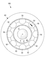
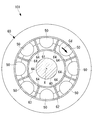
- FIG. 2 is a cross-sectional view taken along the line AA of the gas turbine system shown in FIG. It is a BB arrow view end view of the gas turbine system shown in FIG. It is a CC arrow view end view of the gas turbine system shown in FIG.
- FIG. 5 is a cross-sectional view taken along the line AA of the gas turbine system according to the modified example. It is a vertical sectional view of the gas turbine system which concerns on 2nd Embodiment of this disclosure.
- FIG. 7 is a cross-sectional view taken along the line DD of the gas turbine system shown in FIG.
- FIG. 7 is a cross-sectional view taken along the line EE of the gas turbine system shown in FIG.
- FIG. 1 is a schematic configuration diagram showing an aircraft 1 according to the first embodiment of the present disclosure.
- FIG. 2 is a vertical sectional view of the gas turbine system 100 shown in FIG.
- FIG. 3 is a cross-sectional view taken along the line AA of the gas turbine system 100 shown in FIG.
- FIG. 4 is an end view taken along the line BB of the gas turbine system 100 shown in FIG.
- FIG. 5 is an end view taken along the line CC of the gas turbine system 100 shown in FIG.
- the aircraft 1 includes a gas turbine system 100 that generates electric power and an electric fan (thrust generator) 200 that generates thrust by the electric power generated by the gas turbine system 100.
- the aircraft 1 of the present embodiment is a device that drives an electric fan 200 with electric power generated by a gas turbine system 100 to obtain thrust.
- the gas turbine system 100 includes a compressor 10, a combustor 20, a turbine 30, a first generator 40, a plurality of second generators 50, and an exhaust unit 60. , Nasser 70, and so on. As shown in FIG. 1, the electric power generated by the first generator 40 and the second generator 50 is supplied to the electric fan 200.
- the compressor 10 is a device that compresses the external air flowing in from the front in the traveling direction of the aircraft 1 to generate compressed air.
- the compressor 10 has a plurality of moving blades 11 rotating around the axis X and a plurality of fixed stationary blades 12, and allows the inflowing air to pass through the plurality of moving blades 11 and the plurality of stationary blades 12. Generates compressed air.
- the combustor 20 is a device that burns compressed air generated by the compressor 10 together with fuel to generate high-temperature and high-pressure combustion gas.
- the combustor 20 rotates the turbine 30 around the axis X by supplying a high-temperature and high-pressure combustion gas to the turbine 30.
- Combustors 20 are provided at a plurality of locations around the axis X.
- the turbine 30 is a device driven by the combustion gas generated by the combustor 20.
- the turbine 30 has a plurality of moving blades 31 rotating around the axis X, a plurality of fixed stationary blades 32, and a drive shaft 33 connected to the moving blades.
- the driving force obtained by rotating the rotor blades 31 is transmitted to the first generator 40 via the drive shaft 33.
- the first generator 40 is a device that is connected to the drive shaft 33 of the turbine 30 and generates electricity by the driving force of the turbine 30.
- the first generator 40 has a rotor (not shown) that is connected to the drive shaft 33 and rotates around the axis X, and a stator that is fixedly arranged around the rotor. As shown in FIG. 1, the electric power generated by the first generator 40 is supplied to the electric fan 200.
- the second generator 50 is a device that generates electric power from the combustion gas that has passed through the turbine 30.
- the second generator 50 converts the kinetic energy of the combustion gas into power for rotating a rotating shaft of a small turbine, a wind turbine, or the like, and drives the generator main body (not shown) with the power to generate power. It is a device.
- the second generator 50 is a device that converts the thermal energy of the combustion gas into electric power based on, for example, the temperature difference between the high-temperature combustion gas and the outside air.
- the second generator 50 may be a device that converts the kinetic energy of the combustion gas into electric power and the thermal energy of the combustion gas into electric power.
- the second generator 50 is a device that converts the kinetic energy and / or thermal energy of the combustion gas that has passed through the turbine 30 into electric power.
- Each of the plurality of second generators 50 has a generator main body (not shown) that generates electric power, and supplies the generated electric power to the electric fan 200.
- each of the plurality of second generators 50 does not have a generator main body (not shown), and a single generator main body may be provided for the plurality of second generators 50.
- the plurality of second generators 50 transmit the driving force to a single generator main body by means of an angle gearbox or the like, and supply electric power from the single generator main body to the electric fan 200.
- the electric fan 200 is a device that generates thrust by the electric power generated by the first generator 40 and the second generator 50.
- the electric fan 200 can be installed at an arbitrary position in the aircraft 1 away from the gas turbine system 100.
- the electric fan 200 obtains thrust by rotating a fan (not shown).
- the exhaust unit 60 guides the combustion gas that has passed through the turbine 30 to the outside.
- the exhaust portion 60 has an inner side wall portion 61 and an outer wall portion 62.
- the inner side wall portion 61 extends along the axis X on which the turbine 30 rotates and is formed in a tubular shape around the axis X.
- the outer side wall portion 62 extends along the axis X and is formed in a tubular shape, and is arranged so as to surround the outer peripheral side of the inner side wall portion 61.
- the inner side wall portion 61 and the outer wall portion 62 circulate the combustion gas discharged from the turbine 30 and form an annular flow path 63 extending along the axis X.
- the annular flow path 63 is a flow path formed in an annular shape about the axis X, and guides the entire amount of combustion gas discharged from the turbine 30 to the outside.
- a storage space S1 surrounded by the inner side wall portion 61 is formed on the inner peripheral side of the inner side wall portion 61 with respect to the axis X.
- a first generator 40 is arranged in the storage space S1. The first generator 40 is fixed to the inner side wall portion 61 via a fixture (not shown).
- the second generator 50 is arranged at a plurality of locations of the annular flow path 63 at the same position along the axis X. As shown in FIG. 3, the second generators 50 are arranged at a plurality of equidistant locations (8 locations at 45 ° intervals in FIG. 3) along the circumferential direction Cd centered on the axis X.
- the second generator 50 converts the kinetic energy and / or thermal energy of the combustion gas that has passed through the turbine 30 into electric power by circulating the combustion gas inside.
- the position P1 on the axis X is a position corresponding to the downstream end of the second generator 50 in the flow direction of the combustion gas.
- the outer diameter of the inner side wall portion 61 at the position P1 is Di1. Further, the inner diameter of the outer wall portion 62 at the position P1 is Do1.
- the cross-sectional area of the annular flow path 63 at the position P1 is AR1.
- the position P2 on the axis X is a position corresponding to the downstream end of the annular flow path 63 in the flow direction of the combustion gas.
- the outer diameter of the inner side wall portion 61 at the position P2 is Di2.
- the inner diameter of the outer wall portion 62 at the position P2 is Do2.
- the cross-sectional area of the annular flow path 63 at the position P2 is AR2.
- the cross-sectional area AR2 of the annular flow path 63 at the position P2 is larger than the cross-sectional area AR1 of the annular flow path 63 at the position P1.
- the annular flow path 63 has a diffuser shape in which the cross-sectional area gradually increases toward the downstream side in the flow direction of the combustion gas at each position from the position P1 to the position P2.
- the combustion gas discharged from the turbine 30 has a velocity component in the circumferential direction Cd along the rotation direction of the turbine 30.
- a part of the velocity component of the circumferential direction Cd of the combustion gas is along the axis X. It is preferable to convert it into a velocity component.
- a part of the velocity component of the circumferential direction Cd of the combustion gas is a velocity along the axis X. It is preferable to convert it into a component.
- a plurality of locations Cd in the circumferential direction of the annular flow path 63 are located upstream of the position P0 in the annular flow path 63 in the flow direction of the combustion gas.
- a rectifying plate (rectifying portion) 64 connecting the inner side wall portion 61 and the outer wall portion 62 may be arranged in The straightening vane 64 is a plate-shaped member extending so as to be orthogonal (intersecting) with the circumferential direction Cd, and divides the annular flow path 63 into a plurality of regions along the circumferential direction Cd.
- the position P0 corresponds to the position where the upstream end of the second generator 50 is arranged in the X direction of the axis.
- the straightening vane 64 extends so as to be orthogonal to the circumferential direction Cd, when the combustion gas collides with the straightening vane 64, a part of the velocity component of the circumferential direction Cd of the combustion gas becomes a velocity component along the axis X. Will be converted. As a result, the combustion gas in which the velocity component in the circumferential direction Cd is reduced and the velocity component along the axis X is increased can be guided to the second generator 50 as compared with the case where the straightening vane 64 is not provided.
- the nacelle 70 is an outer shell arranged so as to cover each part of the gas turbine system 100 including the compressor 10, the combustor 20, the turbine 30, and the exhaust part 60.
- the nacelle 70 is formed in a tubular shape extending along the axis X.
- the nacelle 70 is connected to the aircraft body (not shown) via a pylon (not shown).
- the aircraft 1 includes a compressor 10 that compresses external air to generate compressed air, a combustor 20 that burns compressed air generated by the compressor 10 together with fuel to generate combustion gas, and combustion.
- a turbine 30 driven by a combustion gas generated by a vessel 20, a first generator 40 connected to the turbine 30 to generate electricity by driving the turbine 30, and an electric motor that generates a thrust by the power generated by the first generator 40.
- It includes a fan 200 and a second generator 50 that is arranged downstream of the combustion gas in the flow direction and converts kinetic energy and / or thermal energy of the combustion gas that has passed through the turbine 30 into electric power.
- the turbine 30 is driven by the combustion gas generated by the combustor 20, and the first generator 40 connected to the turbine 30 generates electricity by driving the turbine 30. Since the electric fan 200 generates thrust by the electric power generated by the first generator 40, the aircraft 1 can be propelled.
- the kinetic energy and / or thermal energy of the combustion gas driving the turbine 30 is converted into electric power by the second generator 50 arranged on the downstream side of the turbine 30 in the flow direction of the combustion gas. Therefore, in the aircraft 1 including the first generator 40 and the second generator 50 that generate electricity by driving the turbine 30, and the electric fan 200 that generates thrust by electric power, the kinetic energy of the combustion gas used to drive the turbine 30 And / or heat energy can be used effectively.
- the aircraft 1 includes an exhaust unit 60 that guides the combustion gas that has passed through the turbine 30 to the outside, and the exhaust unit 60 extends along the axis X on which the turbine 30 rotates and has an inner side wall formed in a tubular shape.
- the first generator 40 is a storage space S1 formed on the inner peripheral side of the inner side wall portion 61.
- the second generator 50 is arranged in the annular flow path 63.
- the first generator 40 is arranged in the storage space S1 formed on the inner peripheral side of the inner side wall portion 61 of the exhaust portion 60, the first generator 40 is used as a combustion gas. Can be placed in a space where is not distributed. Further, since the second generator 50 is arranged in the annular flow path 63 formed by the inner side wall portion 61 and the outer wall portion 62 of the exhaust portion 60, the combustion gas discharged from the turbine 30 is surely collected by the second generator. It can lead to 50.
- the annular flow path 63 has a diffuser shape in which the cross-sectional area gradually increases from the position where the second generator 50 is arranged toward the downstream side in the flow direction of the combustion gas. Since the annular flow path 63 has a diffuser shape, when the combustion gas that has passed through the second generator 50 is discharged to the outside, the combustion gas flow is decelerated and the pressure is increased, so that the efficiency of the entire turbine 30 is improved. Can be done. In order to suppress the peeling phenomenon due to the increase in the pressure of the combustion gas, it is desirable that the inner side wall portion 61 and the outer wall portion 62 have a shape that suppresses the separation of the combustion gas flow from them.
- the second generators 50 are arranged at a plurality of locations in the circumferential direction around the axis X of the annular flow path 63. Since the second generators 50 are arranged at a plurality of locations in the circumferential direction of the annular flow path 63, each of the plurality of second generators 50 powers the kinetic energy and / or thermal energy of the combustion gas that has passed through the turbine 30. Can be converted to.
- a plurality of second generators 50 are arranged in an annular flow path 63 formed between the inner side wall portion 61 and the outer wall portion 62. ..
- a plurality of second generators 50 are arranged in each of the plurality of discrete flow paths 65Aa in which the combustion gas flowing into the annular flow path 63A is distributed. Is.
- FIG. 7 is a vertical sectional view of the gas turbine system 100A according to the present embodiment.
- FIG. 8 is a cross-sectional view taken along the line DD of the gas turbine system 100A shown in FIG.
- FIG. 9 is a cross-sectional view taken along the line EE of the gas turbine system 100A shown in FIG.
- the exhaust unit 60A of the present embodiment and the exhaust unit 60 of the first embodiment are common in that the combustion gas that has passed through the turbine 30 is guided to the outside, but the specific structure is different.
- the exhaust unit 60A of the present embodiment will be described.
- the exhaust portion 60A of the present embodiment includes an inner side wall portion 61A, an outer wall portion 62A, and a distribution portion 65A.
- the inner side wall portion 61A and the outer wall portion 62A circulate the combustion gas discharged from the turbine 30 and form an annular flow path 63A extending along the axis X.
- the annular flow path 63A is a flow path formed in an annular shape about the axis X, and guides the entire amount of combustion gas discharged from the turbine 30 to the outside.
- the combustion gas flowing into the annular flow path 63A is discharged to the outside via the distribution unit 65A.
- the distribution unit 65A is a member that distributes the combustion gas flowing into the annular flow path 63A to a plurality of discrete flow paths 65Aa arranged at a plurality of locations in the circumferential direction Cd around the axis X.
- the distribution unit 65A has a three-dimensional shape that substantially evenly distributes the entire amount of combustion gas flowing through the annular flow path 63A to a plurality of discrete flow paths 65Aa toward the downstream side in the flow direction.
- the total amount of the combustion gas flowing from the annular flow path 63A into the distribution section 65A is distributed to the plurality of discrete flow paths 65Aa and discharged to the outside through each of the discrete flow paths 65Aa.
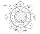
- FIG. 9 is a cross-sectional view taken along the line EE of the gas turbine system 100A shown in FIG. 7, showing a cross section of a plurality of discrete flow paths 65Aa.
- each of the plurality of discrete flow paths 65Aa is a flow path having a circular cross-sectional view, and is spaced along the circumferential direction Cd around the axis X (8 locations at 45 ° intervals in FIG. 9). ) They are arranged discretely. Since the entire amount of the combustion gas flowing through the annular flow path 63A is guided to the plurality of discrete flow paths 65Aa, the combustion gas is not guided from the annular flow path 63A to the storage space S1 in which the first generator 40 is arranged.
- the second generator 50 of the present embodiment is arranged in each of the plurality of discrete flow paths 65Aa at the same position along the axis X.
- the second generator 50 is provided at a plurality of equally spaced locations (8 locations at 45 ° intervals in FIGS. 8 and 9) along the circumferential direction Cd centered on the axis X. Have been placed.
- the second generator 50 converts the kinetic energy and / or thermal energy of the combustion gas that has passed through the turbine 30 into electric power by circulating the combustion gas inside.
- the total cross-sectional area of the plurality of discrete flow paths 65Aa is sufficiently smaller than the cross-sectional area of the annular flow path 63A. Therefore, the flow velocity of the combustion gas led from the annular flow path 63A to the discrete flow path 65Aa increases, and the combustion gas flows into the second generator 50 in a state where the kinetic energy is increased. Therefore, the energy recovery efficiency from the combustion gas by the second generator 50 is increased as compared with the first embodiment in which a part of the combustion gas does not pass through the second generator 50.
- the position P3 on the axis X is a position corresponding to the downstream end of the second generator 50 in the flow direction of the combustion gas.
- the inner diameter of the discrete flow path 65Aa at position P3 is Dd1.
- the position P4 on the axis X is a position corresponding to the downstream end of the discrete flow path 65Aa in the flow direction of the combustion gas.
- the inner diameter of the discrete flow path 65Aa at position P4 is Dd2.
- the inner diameter Dd2 of the discrete flow path 65Aa at the position P4 is larger than the inner diameter Dd1 of the discrete flow path 65Aa at the position P3.
- the discrete flow path 65Aa has a diffuser shape in which the cross-sectional area gradually increases toward the downstream side in the flow direction of the combustion gas at each position from the position P3 to the position P4.
- the aircraft 1 includes an exhaust unit 60A that guides the combustion gas that has passed through the turbine 30 to the outside, and the exhaust unit 60A extends along the axis X on which the turbine 30 rotates and has an inner side wall formed in a tubular shape. It has a portion 61A and an outer wall portion 62A that extends along the axis X and is formed in a tubular shape and is arranged so as to surround the outer peripheral side of the inner side wall portion 61A, and has an inner wall portion 61A and an outer wall portion 62A.
- a plurality of combustion gases discharged from the turbine 30 are circulated and an annular flow path 63A is formed around the axis X, and the combustion gas flowing into the annular flow path 63A is arranged at a plurality of locations in the circumferential direction around the axis X.
- the first generator 40 is arranged in the storage space S1 formed on the inner peripheral side of the inner side wall portion 61, and the second generator 50 is a plurality of discrete passages 65A. It is arranged in each of the flow paths 65Aa.
- the first generator 40 is arranged in the storage space S1 formed on the inner peripheral side of the inner side wall portion 61, the first generator 40 is placed in a space where combustion gas does not flow. Can be placed.
- the combustion gas discharged from the turbine 30 flows into the annular flow path 63A formed by the inner side wall portion 61A and the outer wall portion 62A, and is arranged at a plurality of locations in the circumferential direction by the distribution portion 65A. It is distributed to each of.
- the second generator 50 is arranged in each of the plurality of discrete flow paths 65Aa, the total amount of the combustion gas discharged from the turbine 30 can be reliably guided to the plurality of second generators 50.
- the discrete flow path 65Aa has a diffuser shape in which the cross-sectional area gradually increases from the position where the second generator 50 is arranged toward the downstream side in the flow direction of the combustion gas. Since the discrete flow path 65Aa has a diffuser shape, when the combustion gas that has passed through the second generator 50 is discharged to the outside, the combustion gas flow is decelerated and the pressure is increased, so that the efficiency of the entire turbine 30 is improved. Can be done. In addition, in order to suppress the peeling phenomenon due to the increase in the pressure of the combustion gas, it is desirable that the shape of the wall surface of the discrete flow path 65Aa is a shape that suppresses the peeling of the combustion gas flow from the wall surface.
- the annular flow path 63 of the first embodiment has a diffuser shape in which the cross-sectional area gradually increases from the position where the second generator 50 is arranged toward the downstream side in the flow direction of the combustion gas, but other It may be an embodiment.
- the annular flow path 63 may be a flow path whose cross-sectional area does not change from the position where the second generator 50 is arranged toward the downstream side in the flow direction of the combustion gas.
- the discrete flow path 65Aa of the second embodiment has a diffuser shape in which the cross-sectional area gradually increases from the position where the second generator 50 is arranged toward the downstream side in the flow direction of the combustion gas, but other It may be an embodiment.
- the discrete flow path 65Aa may be a flow path whose cross-sectional area does not change from the position where the second generator 50 is arranged toward the downstream side in the flow direction of the combustion gas.
- the gas turbine system described in the present embodiment described above is grasped as follows, for example.
- the gas turbine system (100) according to the present disclosure is used for a moving body (1) including a thrust generator (200) that generates thrust by electric power, and is a compressor (10) that compresses external air to generate compressed air. ), A combustor (20) that burns compressed air generated by the compressor (10) together with fuel to generate combustion gas, and a turbine (30) driven by the combustion gas generated by the combustor (20).
- the first generator (40) which is connected to the turbine (30) and generates power by driving the turbine (30) and supplies power to the thrust generator (200), and the flow of combustion gas rather than the turbine (30).
- the thrust generator (200) is, for example, an electric fan 200.
- the moving body (1) is, for example, an aircraft that obtains thrust by an electric fan 200.
- the turbine (30) is driven by the combustion gas generated by the combustor (20), and is connected to the turbine (30) by the drive of the turbine (30).
- the generator (40) generates electricity. Since the thrust generator (200) generates thrust by the electric power generated by the first generator (40), the moving body (1) can be propelled. Further, the kinetic energy and / or thermal energy of the combustion gas that drives the turbine (30) is converted into electric power by the second generator (50) arranged downstream of the turbine (30) in the flow direction of the combustion gas. Will be done.
- a moving body (1) including a generator (40, 50) that generates electricity by driving the turbine (30) and a thrust generator (200) that generates thrust by electric power.
- the kinetic energy and / or thermal energy of the combustion gas can be effectively utilized.
- the gas turbine system (100) includes an exhaust unit (60) that guides combustion gas that has passed through the turbine (30) to the outside, and the exhaust unit (60) is an axis (X) on which the turbine (30) rotates. ), And an inner side wall portion (61) that extends along the axis (X) and is formed in a tubular shape, and is arranged so as to surround the outer peripheral side of the inner side wall portion (61).
- the outer side wall portion (61) and the outer wall portion (62) have an outer wall portion (62), and the combustion gas discharged from the turbine (30) flows and extends along the axis (X).
- An annular flow path (63) is formed, the first generator (40) is arranged in a storage space (S1) formed on the inner peripheral side of the inner side wall portion (61), and the second generator (50) is arranged. , Arranged in the annular flow path (63).
- the first generator (40) is arranged in the storage space (S1) formed on the inner peripheral side of the inner side wall portion (61) of the exhaust portion (60). Therefore, the first generator (40) can be arranged in a space where the combustion gas does not flow. Further, since the second generator (50) is arranged in the annular flow path (63) formed by the inner side wall portion (61) and the outer wall portion (62) of the exhaust portion (60), the second generator (50) is arranged from the turbine (30). The exhausted combustion gas can be reliably guided to the second generator (50).
- the cross-sectional area of the annular flow path (63) gradually increases from the position where the second generator (50) is arranged toward the downstream side in the flow direction of the combustion gas. It has a diffuser shape. Since the annular flow path (63) has a diffuser shape, when the combustion gas that has passed through the second generator (50) is discharged to the outside, the combustion gas flow is decelerated and the pressure increases, and the entire turbine (30) Efficiency can be improved.
- the second generators (50) are arranged at a plurality of locations in the circumferential direction around the axis (X) of the annular flow path (63). Since the second generator (50) is arranged at a plurality of locations in the circumferential direction of the annular flow path (63), the movement of the combustion gas passing through the turbine (30) in each of the plurality of second generators (50). Energy and / or thermal energy can be converted to electricity.
- the gas turbine system (100) according to the present disclosure is arranged at a plurality of locations in the circumferential direction around the axis (X) of the annular flow path (63) and is in the flow direction of the combustion gas rather than the second generator (50).
- a rectifying unit (64) arranged on the upstream side is provided, and the rectifying unit (64) is a plate-shaped member that connects the inner side wall portion (61) and the outer wall portion (62) and extends so as to intersect the circumferential direction. is there.
- a plurality of rectifying units (64) are arranged in the annular flow path (63) on the upstream side in the flow direction of the combustion gas from the second generator (50). ..
- the rectifying portion (64) is a plate-shaped member that connects the inner side wall portion (61) and the outer wall portion (62) and extends so as to intersect the circumferential direction
- the combustion gas collides with the rectifying portion (64).
- a part of the velocity component in the circumferential direction (Cd) of the combustion gas is converted into the velocity component along the axis (X).
- the combustion gas in which the velocity component in the circumferential direction (Cd) is reduced and the velocity component along the axis (X) is increased is guided to the second generator 50 as compared with the case where the rectifying unit (64) is not provided. be able to.
- the gas turbine system (100) includes an exhaust unit (60A) that guides combustion gas that has passed through the turbine (30) to the outside, and the exhaust unit (60A) is an axis (X) on which the turbine (30) rotates. ), And an inner side wall portion (61A) that extends along the axis (X) and is formed in a tubular shape, and is arranged so as to surround the outer peripheral side of the inner side wall portion (61A).
- the outer wall portion (62A) and the inner side wall portion (61A) and the outer wall portion (62A) allow the combustion gas discharged from the turbine (30) to flow and a circular flow around the axis (X).
- a distribution unit (65A) that forms a path (63A) and distributes the combustion gas that has flowed into the annular flow path (63A) to a plurality of discrete flow paths (65Aa) arranged at a plurality of locations in the circumferential direction around the axis (X).
- the first generator (40) is arranged in the storage space (S1) formed on the inner peripheral side of the inner side wall portion (61), and the second generator (50) has a plurality of discrete flow paths. It is arranged in each of (65Aa).
- the first generator (40) is arranged in the storage space (S1) formed on the inner peripheral side of the inner side wall portion (61), the first power generation The machine (40) can be arranged in a space where combustion gas does not flow.
- the combustion gas discharged from the turbine (30) flows into the annular flow path (63A) formed by the inner side wall portion (61A) and the outer wall portion (62A), and is provided at a plurality of locations in the circumferential direction by the distribution portion (65A). It is distributed to each of a plurality of discrete channels (65Aa) arranged in. Since the second generator (50) is arranged in each of the plurality of discrete flow paths (65Aa), the total amount of combustion gas discharged from the turbine (30) is surely guided to the plurality of second generators (50). be able to.
- the cross-sectional area of the discrete flow path (65Aa) gradually increases from the position where the second generator (50) is arranged toward the downstream side in the flow direction of the combustion gas. It has a diffuser shape. Since the discrete flow path (65Aa) has a diffuser shape, when the combustion gas that has passed through the second generator (50) is discharged to the outside, the combustion gas flow is decelerated and the pressure increases, and the entire turbine (30) Efficiency can be improved.
- the mobile body described in the present embodiment described above is grasped as follows, for example.
- the moving body (1) according to the present disclosure includes a gas turbine system (100) according to any one of the above, and a thrust generator (200) that generates thrust by electric power generated by the gas turbine system (100). Be prepared.
- a gas turbine system (100) used in a moving body (1) including a generator (40) that generates electricity by driving a turbine (30) and a thrust generator (200) that generates thrust by electric power.
- the kinetic energy and / or thermal energy of the combustion gas used to drive the turbine (30) can be effectively utilized.
Landscapes
- Engineering & Computer Science (AREA)
- Mechanical Engineering (AREA)
- General Engineering & Computer Science (AREA)
- Chemical & Material Sciences (AREA)
- Combustion & Propulsion (AREA)
- Aviation & Aerospace Engineering (AREA)
- Connection Of Motors, Electrical Generators, Mechanical Devices, And The Like (AREA)
- Wind Motors (AREA)
Priority Applications (2)
| Application Number | Priority Date | Filing Date | Title |
|---|---|---|---|
| US17/625,249 US11713691B2 (en) | 2019-07-12 | 2020-02-13 | Gas turbine system and moving unit including the same |
| DE112020003367.8T DE112020003367B4 (de) | 2019-07-12 | 2020-02-13 | Gasturbinensystem und Bewegungskörper, die selbige beinhaltet |
Applications Claiming Priority (2)
| Application Number | Priority Date | Filing Date | Title |
|---|---|---|---|
| JP2019130170A JP7293014B2 (ja) | 2019-07-12 | 2019-07-12 | ガスタービンシステムおよびそれを備えた移動体 |
| JP2019-130170 | 2019-07-12 |
Publications (1)
| Publication Number | Publication Date |
|---|---|
| WO2021009954A1 true WO2021009954A1 (ja) | 2021-01-21 |
Family
ID=74210525
Family Applications (1)
| Application Number | Title | Priority Date | Filing Date |
|---|---|---|---|
| PCT/JP2020/005612 Ceased WO2021009954A1 (ja) | 2019-07-12 | 2020-02-13 | ガスタービンシステムおよびそれを備えた移動体 |
Country Status (4)
| Country | Link |
|---|---|
| US (1) | US11713691B2 (https=) |
| JP (1) | JP7293014B2 (https=) |
| DE (1) | DE112020003367B4 (https=) |
| WO (1) | WO2021009954A1 (https=) |
Citations (8)
| Publication number | Priority date | Publication date | Assignee | Title |
|---|---|---|---|---|
| JPH11200888A (ja) * | 1998-01-19 | 1999-07-27 | Mitsubishi Heavy Ind Ltd | 燃料電池式タービンエンジン |
| JP2006205755A (ja) * | 2005-01-25 | 2006-08-10 | Japan Aerospace Exploration Agency | 航空機用推進システム |
| US20070095379A1 (en) * | 2005-10-31 | 2007-05-03 | Taher Mahmoud A | Thermoelectric generator |
| JP2008064100A (ja) * | 2006-09-08 | 2008-03-21 | General Electric Co <Ge> | エネルギー抽出システムの効率を高めるためのデバイス |
| JP2009293390A (ja) * | 2008-06-02 | 2009-12-17 | Honda Motor Co Ltd | ガスタービンエンジン |
| JP2012039858A (ja) * | 2010-08-03 | 2012-02-23 | General Electric Co <Ge> | タービンエンジンから発生した廃熱を利用する熱電素子の乱流配置 |
| JP2017194054A (ja) * | 2016-04-18 | 2017-10-26 | ゼネラル・エレクトリック・カンパニイ | ガス軸受を有する回転機械 |
| US20180050806A1 (en) * | 2016-08-22 | 2018-02-22 | General Electric Company | Embedded electric machine |
Family Cites Families (5)
| Publication number | Priority date | Publication date | Assignee | Title |
|---|---|---|---|---|
| US7389635B2 (en) * | 2004-12-01 | 2008-06-24 | Honeywell International Inc. | Twisted mixer with open center body |
| US7514810B2 (en) * | 2006-12-15 | 2009-04-07 | General Electric Company | Electric power generation using power turbine aft of LPT |
| US7882696B2 (en) * | 2007-06-28 | 2011-02-08 | Honeywell International Inc. | Integrated support and mixer for turbo machinery |
| US10208641B2 (en) | 2015-11-25 | 2019-02-19 | The Boeing Company | Thermal electric assembly attached on an outer surface of a hot section of a gas turbine engine to generate electrical power |
| US10442547B2 (en) | 2017-06-22 | 2019-10-15 | General Electric Company | Engine and electrical machine health monitoring |
-
2019
- 2019-07-12 JP JP2019130170A patent/JP7293014B2/ja active Active
-
2020
- 2020-02-13 WO PCT/JP2020/005612 patent/WO2021009954A1/ja not_active Ceased
- 2020-02-13 DE DE112020003367.8T patent/DE112020003367B4/de active Active
- 2020-02-13 US US17/625,249 patent/US11713691B2/en active Active
Patent Citations (8)
| Publication number | Priority date | Publication date | Assignee | Title |
|---|---|---|---|---|
| JPH11200888A (ja) * | 1998-01-19 | 1999-07-27 | Mitsubishi Heavy Ind Ltd | 燃料電池式タービンエンジン |
| JP2006205755A (ja) * | 2005-01-25 | 2006-08-10 | Japan Aerospace Exploration Agency | 航空機用推進システム |
| US20070095379A1 (en) * | 2005-10-31 | 2007-05-03 | Taher Mahmoud A | Thermoelectric generator |
| JP2008064100A (ja) * | 2006-09-08 | 2008-03-21 | General Electric Co <Ge> | エネルギー抽出システムの効率を高めるためのデバイス |
| JP2009293390A (ja) * | 2008-06-02 | 2009-12-17 | Honda Motor Co Ltd | ガスタービンエンジン |
| JP2012039858A (ja) * | 2010-08-03 | 2012-02-23 | General Electric Co <Ge> | タービンエンジンから発生した廃熱を利用する熱電素子の乱流配置 |
| JP2017194054A (ja) * | 2016-04-18 | 2017-10-26 | ゼネラル・エレクトリック・カンパニイ | ガス軸受を有する回転機械 |
| US20180050806A1 (en) * | 2016-08-22 | 2018-02-22 | General Electric Company | Embedded electric machine |
Also Published As
| Publication number | Publication date |
|---|---|
| JP2021014825A (ja) | 2021-02-12 |
| JP7293014B2 (ja) | 2023-06-19 |
| DE112020003367T5 (de) | 2022-03-31 |
| US20220268168A1 (en) | 2022-08-25 |
| DE112020003367B4 (de) | 2024-08-08 |
| US11713691B2 (en) | 2023-08-01 |
Similar Documents
| Publication | Publication Date | Title |
|---|---|---|
| JP6254756B2 (ja) | 流れ溝を備えるガスタービンノズル | |
| US9194239B2 (en) | Turbine rotor blade and turbo machine | |
| EP3044416B1 (en) | Airfoil component with groups of showerhead cooling holes | |
| JP2019044761A (ja) | エンジンロータ要素回転装置を備えたガスタービンエンジン | |
| JP2013139790A (ja) | 流れフェンスを備えたガスタービンノズル | |
| US12129794B2 (en) | Vane assembly for a gas turbine engine | |
| WO2015195871A1 (en) | Turbine apparatus with counter-rotating blades | |
| JP5397724B2 (ja) | 低圧タービンによる発電方法とその低圧タービンによる発電装置 | |
| US20180171966A1 (en) | Wind turbine with rotating augmentor | |
| US8916986B2 (en) | Impulse air turbine arrangement for use with a reversing bi-directional air flow in a wave power plant | |
| CN216134322U (zh) | 风冷结构、盘式电机及飞行器 | |
| WO2021009954A1 (ja) | ガスタービンシステムおよびそれを備えた移動体 | |
| US11247780B2 (en) | Turbomachine having inner and outer fans with hub-tip ratios | |
| KR102153064B1 (ko) | 터빈 블레이드 및 이를 포함하는 가스 터빈 | |
| US20200102912A1 (en) | Turbomachine | |
| CA2933364C (en) | Advanced distributed engine architecture-design alternative | |
| US11306682B2 (en) | Concentric turbomachine with trailing edge | |
| WO2021009953A1 (ja) | ガスタービンシステムおよびそれを備えた移動体 | |
| JP7305472B2 (ja) | ガスタービンシステムおよびそれを備えた移動体 | |
| IT202000018631A1 (it) | Pale di turbina comprendenti elementi di aero-freno e metodi per il loro uso. | |
| US11371467B2 (en) | Concentric turbomachine with electric machine | |
| US11371350B2 (en) | Concentric turbomachine with electric machine | |
| WO2018094444A1 (en) | Reverse-flow (rf) rotor | |
| WO2020223544A1 (en) | Expander and nozzle system for converting energy in a working fluid into work | |
| CN113446120A (zh) | 用于冷却反向旋转涡轮发动机的一部分的方法和装置 |
Legal Events
| Date | Code | Title | Description |
|---|---|---|---|
| 121 | Ep: the epo has been informed by wipo that ep was designated in this application |
Ref document number: 20841369 Country of ref document: EP Kind code of ref document: A1 |
|
| 122 | Ep: pct application non-entry in european phase |
Ref document number: 20841369 Country of ref document: EP Kind code of ref document: A1 |