WO2021006025A1 - 物体識別装置 - Google Patents
物体識別装置 Download PDFInfo
- Publication number
- WO2021006025A1 WO2021006025A1 PCT/JP2020/024509 JP2020024509W WO2021006025A1 WO 2021006025 A1 WO2021006025 A1 WO 2021006025A1 JP 2020024509 W JP2020024509 W JP 2020024509W WO 2021006025 A1 WO2021006025 A1 WO 2021006025A1
- Authority
- WO
- WIPO (PCT)
- Prior art keywords
- bicycle
- identification
- pedestrian
- unit
- image
- Prior art date
Links
Images


Classifications
-
- G—PHYSICS
- G06—COMPUTING; CALCULATING OR COUNTING
- G06V—IMAGE OR VIDEO RECOGNITION OR UNDERSTANDING
- G06V20/00—Scenes; Scene-specific elements
- G06V20/50—Context or environment of the image
- G06V20/56—Context or environment of the image exterior to a vehicle by using sensors mounted on the vehicle
- G06V20/58—Recognition of moving objects or obstacles, e.g. vehicles or pedestrians; Recognition of traffic objects, e.g. traffic signs, traffic lights or roads
-
- G—PHYSICS
- G06—COMPUTING; CALCULATING OR COUNTING
- G06V—IMAGE OR VIDEO RECOGNITION OR UNDERSTANDING
- G06V10/00—Arrangements for image or video recognition or understanding
- G06V10/40—Extraction of image or video features
- G06V10/50—Extraction of image or video features by performing operations within image blocks; by using histograms, e.g. histogram of oriented gradients [HoG]; by summing image-intensity values; Projection analysis
-
- G—PHYSICS
- G06—COMPUTING; CALCULATING OR COUNTING
- G06V—IMAGE OR VIDEO RECOGNITION OR UNDERSTANDING
- G06V40/00—Recognition of biometric, human-related or animal-related patterns in image or video data
- G06V40/10—Human or animal bodies, e.g. vehicle occupants or pedestrians; Body parts, e.g. hands
- G06V40/103—Static body considered as a whole, e.g. static pedestrian or occupant recognition
-
- G—PHYSICS
- G08—SIGNALLING
- G08G—TRAFFIC CONTROL SYSTEMS
- G08G1/00—Traffic control systems for road vehicles
- G08G1/16—Anti-collision systems
- G08G1/166—Anti-collision systems for active traffic, e.g. moving vehicles, pedestrians, bikes
Definitions
- the present invention relates to an object identification device mounted on a vehicle or the like.
- in-vehicle cameras are often used for driving support devices for preventing accidents and automatic driving devices that are controlled by machines instead of being operated by the driver.
- the driving support device It is necessary for the driving support device to detect more objects that may collide, and among them, the function to detect pedestrians and bicycles that are vulnerable to traffic is important.
- Patent Document 1 There is a technique described in Patent Document 1 as a technique for detecting a crossing bicycle in front of a vehicle.
- Patent Document 1 since the technique described in Patent Document 1 considers only the relative positions of the double pedestrian and each part, when the pedestrian crosses in front of the illegally parked bicycle, it is erroneously detected as a cyclist (bicycle including the driver). To do.
- an object of the present invention is to determine whether to perform bicycle identification based on the identification result of the pedestrian classifier, determine the bicycle identification area in consideration of the positions and sizes of the pedestrian and the bicycle in three dimensions, and process the bicycle identification area. It is to realize an object identification device capable of improving the bicycle detection accuracy without increasing the load.
- the present invention is configured as follows.
- a feature amount extraction unit that extracts a feature amount from an image of an object captured by the imaging unit
- a pedestrian identification area setting unit that defines a pedestrian identification area of an image of an object captured by the imaging unit.
- the pedestrian identification unit determines whether or not the image of the pedestrian identification area defined by the pedestrian identification area setting unit is a pedestrian using the feature amount, and the pedestrian identification unit identifies the pedestrian.
- the bicycle identification area setting unit that defines the identification area of the bicycle in the three-dimensional coordinate space from the image of the pedestrian identification area and the bicycle identification area setting unit that defines the area It is provided with a pedestrian identification unit that determines whether or not the image of the identification area is a pedestrian using the feature amount and identifies the pedestrian.
- the bicycle identification area is determined in consideration of the positions and sizes of the pedestrian and the bicycle in three dimensions, and the processing load is determined. It is possible to realize an object identification device capable of improving the bicycle detection accuracy without increasing the number.
- Example 1 of this invention It is a block diagram when Example 1 of this invention is applied to the object identification apparatus mounted on a vehicle. It is a flowchart which shows the processing in the object identification apparatus in Example 1.
- FIG. It is a flowchart which shows the process in the identification processing part in Example 1.
- FIG. It is a figure which shows another example of the flowchart which shows the processing in the identification processing part shown in FIG.
- It is a flowchart which shows the process in the bicycle identification area setting part of Example 1.
- FIG. It is a figure which shows the example which set the bicycle identification area in the bicycle identification area setting part with respect to the bicycle moving in the captured image with distortion.
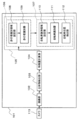
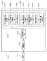
- FIG. 1 is a block diagram when the first embodiment of the present invention is applied to an object identification device mounted on a vehicle.
- the object identification device 101 includes an imaging unit 102 that sets an optimum exposure parameter with a camera 113 mounted on a vehicle and images the image, and a three-dimensional object that detects a three-dimensional object from the image captured by the imaging unit 102. It is provided with an object detection unit 103.
- the object identification device 101 includes a feature amount calculation unit (feature amount extraction unit) 104 that calculates an image feature amount in a region that widely includes a three-dimensional object detection area detected by the three-dimensional object detection unit 103, and a feature amount calculation unit 104. It is provided with an identification processing unit 105 that performs identification using the feature amount calculated in 1.
- a feature amount calculation unit feature amount extraction unit
- an identification processing unit 105 that performs identification using the feature amount calculated in 1.
- the identification processing unit 105 includes a pedestrian identification unit 106 for identifying pedestrians and a bicycle identification unit 107 for identifying bicycles.
- the pedestrian identification unit 106 has a pedestrian identification area setting unit 108 that determines the pedestrian identification area and a pedestrian identification device (1) that determines whether or not the image area defined by the pedestrian identification area setting unit 108 is a pedestrian.
- a pedestrian identification unit) 109 is provided.
- the bicycle identification unit 107 includes a bicycle identification area setting unit 110 that defines a bicycle identification area, and a bicycle identification device (bicycle identification unit) 111 that determines whether or not the image area defined by the bicycle identification area setting unit 110 is a bicycle.
- the bicycle position detecting unit 112 is provided to obtain the traveling direction and the detection area of the bicycle from the result of identification by the bicycle classifier 111.
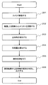
- FIG. 2 is a flowchart showing processing by the object identification device 101.
- Step 201 Using the camera 113 mounted on the vehicle, the optimum exposure parameter of the frame to be captured this time is calculated from the frame previously captured by the imaging unit 102, and the image captured by that parameter is acquired.
- the camera 113 may be provided with an image sensor such as a CMOS (Complementary Metal Oxide Semiconductor) or a CCD (Charge Coupled Device Image Sensor).
- CMOS Complementary Metal Oxide Semiconductor
- CCD Charge Coupled Device Image Sensor
- Step 202 The image pickup unit 102 corrects the contrast of the image acquired in step 201.
- Step 203 A three-dimensional object is detected from the image obtained by the imaging unit 102.
- the optical flow of the frame F (t) imaged at the current time and the frame F (t-1) frame imaged one frame before is calculated by a known method, and the movement is about the same in the same direction.
- a moving three-dimensional object is detected by grouping the image area of the flow having a quantity.
- Step 204 The feature amount calculation unit 104 calculates the image feature amount of the area in which the three-dimensional object area obtained in step 203 has a margin.
- the feature amount is a known method.
- the image feature amount includes a HOG (Histograms of Oriented Gradients) feature amount in which the brightness gradient direction is histogramd in a local region obtained by dividing the brightness gradient image by H ⁇ V, or a brightness image. It may be a Histogram feature amount whose feature amount is the average brightness difference between the two regions in the local region.
- HOG Holograms of Oriented Gradients
- Step 205 In the identification processing unit 105, the similarity (identification score) between the feature amount calculated in step 204 and the classifier constructed by learning from the training image in advance is calculated, and if the similarity is equal to or more than the threshold value, Outputs the type of three-dimensional object to be identified.
- Step 206 When the same three-dimensional object has the same type in a plurality of frames, the type of the three-dimensional object is determined and output. By determining the type in multiple frames, the accuracy of the type is increased, which has the effect of preventing erroneous vehicle control.
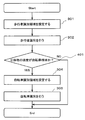
- FIG. 3 is a flowchart showing processing by the identification processing unit 105.
- Step 301 The three-dimensional object detection area detected by the three-dimensional object detection unit 103 is expanded by the pedestrian identification area setting unit 108 by a threshold value or more, and the area is set as the pedestrian identification area.
- the threshold of the extended region is set to 15%.
- Step 302 Using the pedestrian classifier 109 in which the image of the pedestrian identification area set in step 301 is learned in advance from the training image, it is determined whether or not the person is a pedestrian from the feature amount calculated by the feature amount calculation unit 104. Perform pedestrian identification. For example, the pedestrian identification area set in step 301 may be raster-scanned to calculate the pedestrian identification score. Further, not only the pedestrian but also the cyclist who is the driver of the bicycle may be added to the training image of the pedestrian classifier 109. By adding the cyclist to the training image, the cyclist can also be identified as a pedestrian.
- Step 303 If the pedestrian identification score calculated in step 302 is equal to or greater than the threshold value, it is determined that the pedestrian or a cyclist riding a bicycle (the cyclist can be identified as a pedestrian), and the bicycle identification unit 107 processes. If the pedestrian identification score calculated in step 302 is equal to or less than the threshold value, the bicycle identification unit 107 is not processed and is output with the type as the background.
- FIG. 4 is a diagram showing another example of a flowchart showing processing by the identification processing unit 105 shown in FIG.
- the difference between the flowchart shown in FIG. 3 and the flowchart shown in FIG. 4 is that step 303 in FIG. 3 is step 401 in the example of FIG.
- Other steps are the same as in FIGS. 3 and 4.
- the speed of the three-dimensional object is calculated by using the result of tracking the three-dimensional object in a plurality of frames by the three-dimensional object detection unit 103, and the speed of the three-dimensional object to be identified is the moving speed of the bicycle. By determining whether it is appropriate, it may be determined whether or not the processing of the bicycle identification unit 107 is performed.
- Step 304 When it is determined in step 303 that the processing of the bicycle identification unit 107 is to be performed, the bicycle identification area setting unit 110 expands the frame to the left and right in the three-dimensional space based on the pedestrian identification area, and then expands the frame.
- the bicycle identification area is determined by converting the left and right three-dimensional space coordinates to the image space coordinates.
- Step 305 The image of the bicycle identification area calculated in step 304 is identified from the feature amount calculated by the feature amount calculation unit 104 using the bicycle classifier 111 learned in advance from the training image.
- the bicycle identification area set in step 304 may be raster-scanned to calculate the bicycle identification score. If the bicycle identification score of the bicycle classifier 111 in the image of the bicycle identification area exceeds the threshold value, the type is identified and output as a bicycle, and if it is equal to or less than the threshold value, the bicycle is identified and output as a pedestrian.
- the number of times the bicycle is identified for all three-dimensional objects is reduced, which has the effect of reducing the processing load.
- step-by-step identification has the effect of solving the problem that it becomes difficult to determine the type when the identification scores of the pedestrian and bicycle classifiers are the same.
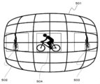
- FIG. 5 is a diagram showing an example showing the result of uniformly determining the expansion amount in the image space for a bicycle moving from right to left in a distorted captured image such as a fisheye camera.
- the angular resolution of one pixel differs between the center of the angle of view and the edge of the angle of view. Therefore, if the amount of expansion is uniformly determined in the image space, the bicycles reflected at the angle of view (for example, the bicycle identification area 503 at the right end and the bicycle identification area 502 at the left end) have less distortion in the central bicycle identification. Compared with the area 504, a frame including a large amount of an extra area other than the bicycle is set, and the bicycle identification performance is lowered.
- the bicycle identification area setting unit 110 an area for performing bicycle identification in the three-dimensional space is determined, and the area determined in the three-dimensional space is converted into image space coordinates to set the bicycle identification area in consideration of distortion. To do.
- FIG. 6 is a flowchart showing processing in the bicycle identification area setting unit 110.
- Step 601 As a result of performing pedestrian identification by the pedestrian identification unit 106, the pedestrian detection coordinates on the image space determined as a pedestrian are acquired.
- Step 602 From the pedestrian detection coordinates acquired in step 601 to calculate the lower end center Ci (the center of the lower end of the pedestrian rectangle) of the pedestrian detection coordinates.
- the lower end center Ci corresponds to the foot position center of the pedestrian, and its coordinate value is used to calculate the distance between the object identification device 101 and the three-dimensional object to be identified by the bicycle.
- Step 603 Convert from the image coordinates of the lower end center Ci to the corresponding position Cw in the three-dimensional space by a known method using camera parameters (for example, the installation height and installation angle of the camera 113, the number of pixels, the lens model, etc.). To do.
- camera parameters for example, the installation height and installation angle of the camera 113, the number of pixels, the lens model, etc.
- Step 604 Calculate the coordinates Aw and Bw obtained by offsetting the position Cw in the three-dimensional space obtained in step 603 to the left and right by a specified amount.
- the offset amount is set to the size of the bicycle specified by law.
- Step 605 The position coordinates Aw and Bw in the three-dimensional space obtained in step 604 are converted into the coordinate values in the image space by using a known method using the camera parameters.
- FIG. 7 is a diagram showing an example in which a bicycle identification area setting unit 110 sets a bicycle identification area for a bicycle moving from right to left in a distorted image such as a fisheye camera.
- the area is set in consideration of the distortion (for example, the bicycle identification area 703 at the right end and the bicycle identification area 702 at the left end). Becomes possible.
- the bicycle identification area defined by the bicycle identification area setting unit 110 is not the bicycle identification areas 502 and 503 including the extra area as shown in FIG. Therefore, there is an effect that the bicycle identification accuracy is improved particularly at the angle of view edge where the distortion is large.
- the bicycle identification area in three dimensions, it is possible to determine the bicycle identification area in consideration of the position and size of the pedestrian and the bicycle, so even in the case where a pedestrian crosses in front of an illegally parked bicycle, walking It has the effect of being correctly detected as a person and preventing misidentification.
- FIG. 8 is a flowchart showing processing by the bicycle position detection unit 112.
- the bicycle position detection unit 112 obtains the detection area including the front wheel of the bicycle, the rear wheel of the bicycle, and the driver of the bicycle.
- Step 801 As a result of performing bicycle identification with the bicycle classifier 111, it is determined whether or not the bicycle identification score is equal to or higher than the threshold value. If the bicycle identification score is equal to or less than the threshold value, the three-dimensional object is likely to be a pedestrian, so the process is completed and the bicycle position detection process is not performed.
- Step 802 The wheel determination area is calculated using the bicycle identification area defined by the bicycle identification area setting unit 110.
- FIG. 9 is an explanatory diagram of an example in which the wheel determination area is defined from the bicycle identification area.
- the wheel determination region 901 is defined as a region in which the height h obtained by multiplying the bicycle identification region height H by the designated magnification from the upper end of the bicycle identification region 902 is offset toward the lower end of the bicycle identification region 902.
- Step 803 In the wheel determination area 901 set in step 802, the wheel is detected by using a known method of circle detection or ellipse detection.
- Step 804 It is determined whether or not both wheels can be detected in the wheel determination area 901 in step 803. For example, both wheels can be detected when the moving direction of the bicycle is other than the front direction and the back direction with respect to the object identification device 101. If it cannot be detected, it is highly possible that the moving direction of the bicycle is the front direction or the back direction with respect to the object identification device 101.
- Step 805 When both wheels can be detected in step 804, the center coordinates of both wheels are obtained, classified into a plurality of patterns from the positional relationship of the center coordinates of the two wheels, and candidates for the moving state are obtained from the relationship between the two wheels.
- FIG. 10 is a diagram showing an example in which the relationship between the center coordinates of both bicycle wheels is classified into three patterns.
- the pattern 1001 when the left and right wheel centers are compared in the vertical direction, there is a relationship that the left wheel center coordinates of the wheel determination region are high and the right wheel center coordinates are low.
- the bicycle is divided into a state in which the bicycle approaches the object identification device 101 in the diagonally right direction and a state in which the bicycle is separated from the object identification device 101 in the diagonal direction to the left.
- the bicycle is divided into a state in which the bicycle is separated from the object identification device 101 in the diagonally right direction and a state in which the bicycle approaches the object identification device 101 in the diagonal direction to the left.
- Step 806 If both wheels cannot be detected in step 804, the height relationship is compared from the height information of the past bicycle identification area and the height information of the current bicycle identification area.
- Step 807 The upper body determination area is calculated using the pedestrian identification area defined by the pedestrian identification area setting unit 108.
- FIG. 11 is a diagram showing an example in which the upper body determination area is defined from the pedestrian identification area.
- the upper body determination area 1101 is defined as an area in which the height h obtained by multiplying the pedestrian identification area height H by the designated magnification from the lower end of the pedestrian identification area 1102 is offset toward the upper end of the pedestrian identification area.
- Step 808 Within the upper body determination area obtained in step 807, a histogram of the luminance gradient within the specified angle is created, and the histogram is classified into a plurality of patterns based on the tendency of the histogram. For example, comparing the preset angular distribution range of the bicycle driver's arm with the histogram of the brightness gradient detected in the upper body judgment area, whether the upper body is facing right or the upper body is facing left 2 Classify into patterns.
- Step 809 If both wheels can be detected in step 803, the traveling direction of the bicycle is calculated using the two-wheel pattern determination result determined in step 805 and the upper body pattern determination result determined in step 808.
- FIG. 13 is a table showing the traveling direction of the bicycle judged from the two-wheel pattern determination result and the upper body pattern determination result.
- the traveling direction of the bicycle can be divided into 6 patterns based on the relationship between the determined two-wheel pattern determination result and the upper body pattern determination result. If both wheels cannot be detected in step 803, increase in the height direction from the height information of the past bicycle identification area 902 obtained in step 806 and the height relationship of the current bicycle identification area 902. For example, it is determined that the object identification device 101 is relatively close to the object identification device 101, and if the height direction is increased, it is determined that the object identification device 101 is relatively close to the object identification device 101.
- the width of the bicycle detection area is calculated from the parameters of the wheels of both wheels obtained in step 803, and the vertical width of the bicycle detection area is calculated by the pedestrian.
- the height is set to the height determined by the identification area setting unit 108.
- both the horizontal width and the vertical width are set to the sizes determined by the pedestrian identification area setting unit 108.
- the bicycle position detection unit 112 obtains the bicycle detection position with higher accuracy than the area determined by the bicycle movement direction and the bicycle identification area setting unit 110, thereby predicting the area where the bicycle exists in the next frame with high accuracy. This makes it possible to obtain a stable bicycle speed, which has the effect of improving the performance of collision detection processing.
- the first embodiment of the present invention after identifying a pedestrian, it is configured to determine whether the pedestrian is a pedestrian or a pedestrian crossing an illegally parked bicycle from the position size of the pedestrian and the bicycle in three dimensions. Therefore, it is possible to realize an object identification device capable of improving the bicycle detection accuracy without increasing the processing load.
- Example 2 Next, Example 2 of the present invention will be described.
- Example 2 of the present invention is an example in which the feature amount calculation unit 104 of the first embodiment is provided in the pedestrian identification unit 106 for identifying a pedestrian and the bicycle identification unit 107 for identifying a bicycle.
- FIG. 12 is a block diagram showing an object recognition device 1201 when the second embodiment of the present invention is applied to an in-vehicle camera.
- the object identification device 1201 distinguishes between an image pickup unit 1202 that sets an optimum exposure parameter by a camera 113 mounted on a vehicle and takes an image, and a three-dimensional object detection unit 1203 that detects a three-dimensional object from the captured image.
- the identification processing unit 1204 is provided.
- the identification processing unit 1204 includes a pedestrian identification unit 1205 for identifying a pedestrian and a bicycle identification unit 1206 for identifying a bicycle.
- the pedestrian identification unit 1205 is defined by the pedestrian identification area setting unit 1207 and the pedestrian identification area setting unit 1207 that determine the pedestrian identification area in the image area of the three-dimensional object detection area detected by the three-dimensional object detection unit 1203. Whether or not the image is a pedestrian from the pedestrian feature amount calculation unit (pedestrian feature amount extraction unit) 1208 that calculates (extracts) the pedestrian feature amount from the image area and the feature amount obtained by the pedestrian feature amount calculation unit 1208. It is provided with a pedestrian discriminator (pedestrian identification unit) 1209 for determining whether or not.
- the bicycle identification unit 1206 calculates (extracts) the bicycle feature amount from the bicycle identification area setting unit 1210 that defines the bicycle identification area and the bicycle identification area defined by the bicycle identification area setting unit 1210.
- a bicycle discriminator (bicycle identification unit) 1212 that determines whether or not the image is a bicycle from the feature amount obtained by the unit (bicycle feature amount extraction unit) 1211 and the bicycle feature amount calculation unit 1211, and the bicycle classifier (bicycle identification unit).
- Bicycle identification unit) 1213 includes a bicycle position detection unit 1213 that obtains the traveling direction and detection area of the bicycle from the result of identification.
- the feature amount calculation unit 104 calculates the feature amount common to the pedestrian and the bicycle.
- the pedestrian feature amount calculation unit 1208 is provided in the pedestrian identification unit 1205 that identifies the pedestrian
- the bicycle feature amount calculation unit 1211 is provided in the bicycle identification unit 1206 that identifies the bicycle. It is provided.
- Example 1 Other configurations are the same as in Example 1 and Example 2.
- the same effect as that of the first embodiment can be obtained, and since the feature amount used by the pedestrian and the bicycle can be changed, there is an effect that the identification accuracy can be improved.
- the present invention is not limited to the above-mentioned examples, and includes various modifications.
- the above-described embodiment has been described in detail in order to explain the present invention in an easy-to-understand manner, and is not necessarily limited to those having all the described configurations.
- the above-mentioned example is an example when the present invention is applied to an object identification device mounted on a vehicle, but it can be applied not only to a vehicle but also to, for example, a surveillance camera installed on a road. Is.
Landscapes
- Engineering & Computer Science (AREA)
- Physics & Mathematics (AREA)
- General Physics & Mathematics (AREA)
- Multimedia (AREA)
- Theoretical Computer Science (AREA)
- Human Computer Interaction (AREA)
- Image Analysis (AREA)
- Traffic Control Systems (AREA)
- Image Processing (AREA)
Abstract
歩行者識別器の識別結果を基に自転車識別を行うかを判定し、3次元上で歩行者と自転車の位置と大きさを考慮し自転車識別領域を定め、処理負荷を増大させずに自転車検出精度を向上可能な物体識別装置を実現する。 物体識別装置101は、撮像部102と、立体物検出部103と、撮像物体の画像から特徴量を抽出する特徴量抽出部104と、識別処理部105を備え、識別処理部105は歩行者識別部106と自転車識別部107を備える。歩行者識別部106は歩行者識別領域設定部108と、歩行者識別領域の画像が歩行者か否かを判定する歩行者識別部109を備える。自転車識別部107は歩行者識別部109により歩行者識別領域の画像が歩行者と判断されたとき、3次元座標空間における自転車の識別領域を定める自転車識別領域設定部110と、自転車の識別領域の画像が自転車か否かを判定し識別する自転車識別部と111とを備える。
Description
本発明は、車両等に搭載される物体識別装置に関する。
近年、事故を未然に防ぐための運転支援装置や、車両を運転者が操作するのではなく、機械が制御する自動運転装置などには車載カメラが用いられることが多くなっている。
運転支援装置ではより多くの衝突可能性がある物体を検出する必要があり、その中でも交通弱者である歩行者や自転車を検知する機能が重要である。
車両前方の横断自転車を検知する技術については、特許文献1に記載の技術がある。
しかしながら、特許文献1に記載の技術では、複歩行者と各パーツの相対位置しか考慮していないため、放置自転車の前を歩行者が横切る際に、サイクリスト(運転者を含む自転車)として誤検知する。
そして、歩行者であるにも拘わらず、サイクリストに対する判断領域を設定し、自車の動作制御を行うこととなる。このため、対象物体に対する高精度の動作制御が困難であった。
そこで、本発明の目的は、歩行者識別器の識別結果を基に自転車識別を行うかを判定し、3次元上で歩行者と自転車の位置と大きさを考慮し自転車識別領域を定め、処理負荷を増大させずに自転車検出精度を向上可能な物体識別装置を実現することである。
上記目的を解決するために、本発明は次のように構成される。
物体識別装置において、撮像部で撮像された物体の画像から特徴量を抽出する特徴量抽出部と、前記撮像部で撮像された物体の画像の歩行者識別領域を定める歩行者識別領域設定部と、前記歩行者識別領域設定部で定めた歩行者識別領域の画像が歩行者か否かを、前記特徴量を用いて判定する歩行者識別部と、前記歩行者識別部により、前記歩行者識別領域の画像が歩行者と判断されたとき、前記歩行者識別領域の画像から3次元座標空間における自転車の識別領域を定める自転車識別領域設定部と、前記自転車識別領域設定部で定めた前記自転車の識別領域の画像が自転車か否かを、前記特徴量を用いて判定し、識別する自転車識別部と、を備える。
本発明によれば、歩行者識別器の識別結果を基に自転車識別を行うかを判定し、3次元上で歩行者と自転車の位置と大きさを考慮し自転車識別領域を定め、処理負荷を増大させずに自転車検出精度を向上可能な物体識別装置を実現することができる。
以下、本発明を車載カメラに適用した実施例を、図面を参照して説明する。
(実施例1)
図1は、本発明の実施例1を車両に搭載される物体識別装置に適用した場合のブロック図である。図1に示すように、物体識別装置101は、車両に搭載されたカメラ113で最適な露光パラメータを設定し撮像する撮像部102と、撮像部102が撮像した画像中から立体物を検出する立体物検出部103とを備える。
図1は、本発明の実施例1を車両に搭載される物体識別装置に適用した場合のブロック図である。図1に示すように、物体識別装置101は、車両に搭載されたカメラ113で最適な露光パラメータを設定し撮像する撮像部102と、撮像部102が撮像した画像中から立体物を検出する立体物検出部103とを備える。
また、物体識別装置101は、立体物検出部103が検出した立体物検出領域を広く包含する領域において画像特徴量を計算する特徴量計算部(特徴量抽出部)104と、特徴量計算部104で計算した特徴量を用いて識別を行う識別処理部105とを備える。
識別処理部105は、歩行者を識別する歩行者識別部106と、自転車を識別する自転車識別部107とを備える。
そして、歩行者識別部106は、歩行者識別領域を定める歩行者識別領域設定部108と、歩行者識別領域設定部108で定めた画像領域が歩行者か否かを判定する歩行者識別器(歩行者識別部)109とを備える。
さらに、自転車識別部107は、自転車の識別領域定める自転車識別領域設定部110と、自転車識別領域設定部110で定めた画像領域が自転車か否かを判定する自転車識別器(自転車識別部)111と、自転車識別器111で識別した結果から自転車の進行方向と検知領域を求める自転車位置検出部112とを備える。
図2は、物体識別装置101での処理を示すフローチャートである。
図2のフローチャートに基づく動作は以下の通りである。
ステップ201:車両に搭載されたカメラ113を用いて撮像部102で前回撮像されたフレームから今回撮像するフレームの最適な露光パラメータを計算し、そのパラメータで撮像した画像を取得する。例えば、カメラ113には、CMOS(Complementary Metal Oxide Semiconductor)やCCD(Charge Coupled Device Image Sensor)などの撮像素子を備えるものであってもよい。
ステップ202:ステップ201で取得した画像のコントラストを撮像部102で補正する。
ステップ203:撮像部102で得られた画像から立体物を検出する。例えば、立体物検出には現在時刻で撮像したフレームF(t)と1フレーム前で撮像したフレームF(t-1)フレームのオプティカルフローを公知の手法で算出し、同一方向に同程度の移動量を持つフローの画像領域をグルーピングすることにより移動する立体物を検出する。
ステップ204:ステップ203で求めた立体物領域にマージンを持たせた領域の画像特徴量を特徴量計算部104で算出する。例えば、特徴量は公知の手法である、画像特徴量には輝度勾配画像をH×Vで分割した局所領域で輝度勾配方向をヒストグラム化したHOG(Histograms of Oriented Gradients)特徴量や、輝度画像の局所領域で2つの領域の平均輝度差を特徴量とするHaar-like特徴量でもよい。
ステップ205:識別処理部105において、ステップ204で計算した特徴量と、前もって訓練画像で学習し構築した識別器との類似度(識別スコア)を算出し、その類似度が閾値以上であれば、識別対象立体物の種別を出力する。
ステップ206:複数フレームで同じ立体物が同じ種別であった場合に立体物の種別を確定し出力する。複数フレームで種別を判定することで種別確度が高まり、誤った車両制御を防ぐ効果がある。
図3は、識別処理部105での処理を示すフローチャートである。
図3のフローチャートに基づく動作は以下の通りである。
ステップ301:立体物検出部103で検出した立体物検知領域を、歩行者識別領域設定部108で閾値以上拡張した領域を歩行者識別領域として設定する。例えば、拡張領域の閾値は15%に設定する。
ステップ302:ステップ301で設定した歩行者識別領域の画像をあらかじめ訓練画像で学習した歩行者識別器109を用いて、特徴量計算部104で計算した特徴量から、歩行者か否かを判断する歩行者識別を実施する。例えば、ステップ301で設定した歩行者識別領域をラスタスキャンし、歩行者識別スコアを算出してもよい。また、歩行者識別器109の訓練画像には、歩行者だけでなく自転車の運転者であるサイクリストを加えてもよい。サイクリストも訓練画像に加えることで、サイクリストも歩行者として識別可能になる。
ステップ303:ステップ302で算出した歩行者識別スコアが閾値以上であれば、歩行者又は自転車に乗ったサイクリスト(サイクリストは歩行者として識別可能)と判断し、自転車識別部107の処理を実施する。ステップ302で算出した歩行者識別スコアが閾値以下であれば自転車識別部107の処理は実施せず、種別を背景とし出力する。
図4は、図3に示した識別処理部105での処理を示すフローチャートの別例を示す図である。図3に示したフローチャートと図4に示したフローチャートとの相違点は、図3におけるステップ303が図4の例ではステップ401となっている点である。その他のステップは図3と図4とは同様となっている。
図4の例におけるステップ401のように、立体物検出部103において複数フレームで立体物をトラッキングした結果を用いて、立体物の速度を算出し、識別対象の立体物の速度が自転車の移動速度相当であるか判定することで、自転車識別部107の処理を実施するか判定してもよい。
ステップ304:ステップ303で自転車識別部107の処理を実施すると判定された場合、自転車識別領域設定部110で歩行者の識別領域を基に3次元空間上で左右に枠を拡張し、その後、拡張した左右の3次元空間座標から画像空間座標に変換することで自転車識別領域を定める。
ステップ305:ステップ304で算出した自転車識別領域の画像を、あらかじめ訓練画像で学習した自転車識別器111を用いて、特徴量計算部104で計算した特徴量から識別を行う。例えば、ステップ304で設定した自転車識別領域をラスタスキャンし、自転車識別スコアを算出してもよい。自転車識別領域の画像における自転車識別器111の自転車識別スコアが、閾値を越えれば種別を自転車として識別して出力し、閾値以下であれば歩行者として識別して出力する。
歩行者識別スコアを基に自転車識別部107の処理を実施するか判定することにより、すべての立体物に対して自転車の識別を行う回数が減少し、処理負荷が低減する効果がある。
また、段階的に識別を行うことによって、歩行者、自転車の識別器の識別スコアが同値であった場合に種別の判定が困難になる課題を解決できる効果がある。
図5は、魚眼カメラのような歪みがある撮像画像内において右から左へと移動する自転車に対し、画像空間上で拡張量を一律に定めた結果を表した例を示す図である。
図5において、歪みのある撮像画像501では、1画素が持つ角度分解能が画角中央と画角端で異なる。このため、画像空間上で拡張量を一律に定めてしまうと、画角端に写る自転車(例えば、右端の自転車識別領域503と左端の自転車識別領域502)には、歪が少ない中央の自転車識別領域504と比較し、自転車以外の余分な領域を多く含む枠が設定され、自転車識別性能が低下する。
そこで、自転車識別領域設定部110において、3次元空間上で自転車識別を行うエリアを決定し、3次元空間上で定めたエリアを画像空間座標に変換することで歪みを考慮した自転車識別領域を設定する。
図6は、自転車識別領域設定部110での処理を示すフローチャートである。
図6のフローチャートに基づく動作は以下の通りである。
ステップ601:歩行者識別部106で歩行者識別を実施した結果、歩行者として判断された画像空間上での歩行者検知座標を取得する。
ステップ602:ステップ601で取得した歩行者検知座標から、歩行者検知座標の下端中心Ci(歩行者矩形の下端部の中心)を計算する。ここで、下端中心Ciは歩行者の足元位置中心にあたり、その座標値が物体識別装置101と自転車識別対象の立体物との距離を計算するために用いられる。
ステップ603:下端中心Ciの画像座標から3次元空間上での対応位置Cwに、カメラパラメータ(例えば、カメラ113の設置高さや取り付け角度、画素数、レンズモデルなど)を用いて公知の手法で変換する。
ステップ604:ステップ603で求めた3次元空間上での位置Cwを左右に指定量分オフセットした座標Aw、Bwを計算する。例えば、オフセット量は、法規で定められた自転車の大きさに設定する。
ステップ605:ステップ604で求めた3次元空間上での位置座標Aw、Bwをそれぞれ画像空間上での座標値にカメラパラメータを用いて公知の手法を用いて変換する。
カメラパラメータを用いて自転車識別領域を設定することで、例えば、カメラの設置位置が変わってもカメラパラメータを修正することで容易に自転車識別領域を設定できる効果がある。
図7は、魚眼カメラのような歪みがある撮像画像内において右から左へと移動する自転車に対し自転車識別領域設定部110で自転車識別領域を設定した例を示す図である。
図7において、歪みがある撮像画像701においても、3次元空間上で自転車識別領域を設定することにより、歪みを考慮した領域設定(例えば、右端の自転車識別領域703、左端の自転車識別領域702)が可能になる。
自転車識別領域設定部110で定めた自転車識別領域では、図5に示したような余分な領域を含んだ自転車識別領域502、503ではない。このため、特に歪みの大きい画角端において自転車識別精度が向上する効果がある。
また、3次元上で自転車識別領域を定めることで、歩行者と自転車の位置と大きさを考慮した自転車識別領域を定めることができるため、放置自転車の前を歩行者が横切るような例でも歩行者として正しく検知され誤識別を防ぐ効果がある。
図8は、自転車位置検出部112での処理を示すフローチャートである。
図8のフローチャートに基づく動作は以下の通りである。
自転車位置検出部112は、自転車の前輪、自転車の後輪および自転車の運転者を含んだ前記検知領域を求める。
ステップ801:自転車識別器111での自転車識別を実施した結果、自転車識別スコアが閾値以上であるか否かを判定する。自転車識別スコアが閾値以下であれば、その立体物は歩行者である可能性が高いため、処理は終了し、自転車位置検出処理は行わない。
ステップ802:自転車識別領域設定部110で定めた自転車識別領域を用いて車輪判定領域を計算する。
図9は、自転車識別領域から車輪判定領域を定めた例の説明図である。
図9において、車輪判定領域901は、自転車識別領域902の上端から自転車識別領域高さHに指定倍率をかけた高さhを自転車識別領域902の下端方向にオフセットした領域として定める。
ステップ803:ステップ802で設定した車輪判定領域901において、公知の手法である円検知や楕円検知を用いて車輪を検出する。
ステップ804:ステップ803で車輪判定領域901にて両輪を検出できたか否かを判定する。例えば、自転車の移動方向が物体識別装置101に対して、正面方向や背面方向以外の場合は両輪を検出できる。検出できなかった場合は、自転車の移動方向が物体識別装置101に対して、正面方向や背面方向である可能性が高い。
ステップ805:ステップ804で両輪が検出できた場合、両輪の中心座標を求め、その両輪の中心座標の位置関係から複数のパターンに分類し、両輪の関係から移動状態の候補を求める。
図10は自転車両輪の中心座標の関係を3パターンに分類した例を示す図である。図10において、パターン1001では、垂直方向で左右の車輪中心を比較すると、車輪判定領域の左側の車輪中心座標が高く、右側の車輪中心座標が低いという関係性がある。この場合、自転車は物体識別装置101に対して右斜め方向に接近する状態か、物体識別装置101に対して左斜め方向に離間する状態かに分けられる。
パターン1002では、垂直方向で左右の車輪中心を比較すると、車輪判定領域の左側の車輪中心座標と右側の車輪中心座標が等しい関係性がある。この場合、自転車は物体識別装置101に対して平行に右方向に移動する状態か、物体識別装置101に対して平行に左方向に移動する状態かに分けられる。
パターン1003では、垂直方向で左右の車輪中心を比較すると、車輪判定領域の左側の車輪中心座標が低く、右側の車輪中心座標が高いという関係性がある。この場合、自転車は物体識別装置101に対して右斜め方向に離間する状態か、物体識別装置101に対して左斜め方向に接近する状態かに分けられる。
ステップ806:ステップ804で両輪が検出できなかった場合、過去の自転車識別領域の高さ情報と現在の自転車識別領域の高さ情報から高さの大小関係比較する。
ステップ807:歩行者識別領域設定部108で定めた歩行者識別領域を用いて上半身判定領域を計算する。
図11は、歩行者識別領域から上半身判定領域を定めた例を示す図である。
図11において、上半身判定領域1101は、歩行者識別領域1102の下端から歩行者識別領域高さHに指定倍率をかけた高さhを歩行者識別領域の上端方向にオフセットした領域として定める。
ステップ808:ステップ807で求めた上半身判定領域内において、指定角度内の輝度勾配のヒストグラムを作成し、そのヒストグラムの傾向から複数パターンに分類する。例えば、あらかじめ設定した自転車の運転者の腕の角度分布範囲と上半身判定領域内において検出した輝度勾配のヒストグラムを比較し、上半身が右方向を向いているか、上半身が左方向を向いているかの2パターンに分類する。
ステップ809:ステップ803で両輪が検出できた場合は、ステップ805で判定した両輪パターン判定結果と、ステップ808で判定した上半身パターン判定結果を用いて自転車の進行方向を算出する。
図13は、両輪パターン判定結果と上半身パターン判定結果から判断する自転車の進行方向示す表である。図13に示すように、例えば、判定した両輪パターン判定結果と上半身パターン判定結果の関係から自転車の進行方向を6パターンに分割できる。ステップ803で両輪が検出できなかった場合は、ステップ806で求めた過去の自転車識別領域902の高さ情報と現在の自転車識別領域902の高さの大小関係から、高さ方向に大きくなっていれば物体識別装置101に対して相対的に接近していると判定し、高さ方向に大きくなっていれば物体識別装置101に対して相対的に離間していると判定する。
自転車検知領域の算出においては、ステップ803で両輪が検出できた場合は、自転車の検知領域の横幅をステップ803で求めた両輪の車輪のパラメータから算出し、自転車の検知領域の縦幅を歩行者識別領域設定部108で定めた高さに設定する。
また、ステップ803で両輪が検出できなかった場合は、横幅、縦幅共に歩行者識別領域設定部108で定めた大きさに設定する。
自転車位置検出部112において、自転車の移動方向と自転車識別領域設定部110で定めた領域より高精度に自転車の検知位置を求めることにより、次フレームでの自転車が存在する領域を高精度に予測することが可能になり、自転車の速度が安定的に求まるため衝突判定処理の性能が向上する効果がある。
本発明の実施例1によれば、歩行者であることを識別した後に、3次元上で歩行者と自転車との位置大きさからサイクリストか放置自転車を横切る歩行者かを判断するように構成したので、処理負荷を増大させずに自転車検出精度を向上可能な物体識別装置を実現することができる。
(実施例2)
次に、本発明の実施例2について説明する。
次に、本発明の実施例2について説明する。
本発明の実施例2は、実施例1における特徴量計算部104を、歩行者を識別する歩行者識別部106と、自転車を識別する自転車識別部107内に設けた例である。
図12は、本発明の実施例2を車載カメラに適用した場合の物体認識装置1201を示すブロック図である。
図12において、物体識別装置1201は、車両に搭載されたカメラ113で最適な露光パラメータを設定し撮像する撮像部1202と、撮像した画像中から立体物を検出する立体物検出部1203と、識別を行う識別処理部1204とを備える。
また、識別処理部1204は、歩行者を識別する歩行者識別部1205と、自転車を識別する自転車識別部1206とを備える。
歩行者識別部1205は、立体物検出部1203が検出した立体物検出領域の画像領域のうちの歩行者識別領域を定める歩行者識別領域設定部1207と、歩行者識別領域設定部1207で定めた画像領域から歩行者の特徴量を算出(抽出)する歩行者特徴量計算部(歩行者特徴量抽出部)1208と、歩行者特徴量計算部1208で求めた特徴量から画像が歩行者か否かを判定する歩行者識別器(歩行者識別部)1209とを備える。
さらに、自転車識別部1206は、自転車の識別領域を定める自転車識別領域設定部1210と、自転車識別領域設定部1210で定めた自転車の識別領域から自転車の特徴量を算出(抽出)する自転車特徴量計算部(自転車特徴量抽出部)1211と、自転車特徴量計算部1211で求めた特徴量から画像が自転車か否かを判定し、識別する自転車識別器(自転車識別部)1212と、自転車識別器(自転車識別部)1212で識別した結果から自転車の進行方向と検知領域を求める自転車位置検出部1213とを備える。
実施例1においては、特徴量計算部104は、歩行者と自転車とで共通の特徴量を計算している。
これに対して、実施例2においては、歩行者を識別する歩行者識別部1205内に歩行者特徴量計算部1208を設け、自転車を識別する自転車識別部1206内に自転車特徴量計算部1211を設けている。
他の構成は、実施例1と実施例2とは、同様となっている。
実施例2によれば、実施例1と同様な効果を得ることができる他、歩行者と自転車で用いる特徴量を変更可能であることから、識別精度を向上することができるという効果がある。
また、識別領域を設定した箇所のみ特徴量を計算することで計算コストが削減できる効果がある。
なお、本発明は上記した実施例に限定されるものではなく、様々な変形例が含まれる。例えば、上記した実施例は本発明を分かりやすく説明するために詳細に説明したものであり、必ずしも説明した全ての構成を備えるものに限定されるものではない。
また、実施例1の構成に実施例2の構成を加えることも可能である。
また、上述した例は、本発明を車両に搭載される物体識別装置に適用した場合の例であるが、車両用のみならず、例えば、道路上に設置される監視カメラに適用することも可能である。
101、1201・・・物体識別装置、102、1202・・・撮像部、103、1203・・・立体物検出部、104・・・特徴量計算部(特徴量抽出部)、105、1204・・・識別処理部、106、1205・・・歩行者識別部、107、1206・・・自転車識別部、108、1207・・・歩行者識別領域設定部、109、1209・・・歩行者識別器(歩行者識別部)、110、1210・・・自転車識別領域設定部、111、1212・・・自転車識別器(自転車識別部)、112、1213・・・自転車位置検出部、113・・・カメラ、502、503、504・・・自転車識別領域、1208・・・歩行者特徴量計算部(歩行者特徴量抽出部)、1211・・・自転車特徴量計算部(自転車特徴量抽出部)
Claims (5)
- 撮像部で撮像された物体の画像から特徴量を抽出する特徴量抽出部と、
前記撮像部で撮像された物体の画像の歩行者識別領域を定める歩行者識別領域設定部と、
前記歩行者識別領域設定部で定めた歩行者識別領域の画像が歩行者か否かを、前記特徴量を用いて判定する歩行者識別部と、
前記歩行者識別部により、前記歩行者識別領域の画像が歩行者と判断されたとき、前記歩行者識別領域の画像から3次元座標空間における自転車の識別領域を定める自転車識別領域設定部と、
前記自転車識別領域設定部で定めた前記自転車の識別領域の画像が自転車か否かを、前記特徴量を用いて判定し、識別する自転車識別部と、
を備えることを特徴とする物体識別装置。 - 請求項1に記載の物体識別装置において、
前記特徴量抽出部は、前記歩行者識別領域設定部で定めた前記歩行者識別領域から歩行者の特徴量を抽出する歩行者特徴量抽出部と、前記自転車識別領域設定部で定めた前記自転車識別領域から自転車の特徴量を抽出する自転車特徴量抽出部とを有し、
前記歩行者識別部は、前記歩行者特徴量抽出部で抽出した歩行者の特徴量から前記歩行者識別領域の画像が歩行者か否かを判定し、
前記自転車識別部は、前記自転車特徴量抽出部で抽出した特徴量から前記自転車識別領域の画像が自転車か否かを判定することを特徴とする物体識別装置。 - 請求項1又は2に記載の物体識別装置において、
前記自転車識別部で識別した前記自転車の進行方向と検知領域を求める自転車位置検出部を備えることを特徴とする物体識別装置。 - 請求項3に記載の物体識別装置において、
前記自転車位置検出部は、前記自転車の前輪、前記自転車の後輪および前記自転車の運転者を含んだ前記検知領域を求めることを特徴とする物体識別装置。 - 請求項1または2に記載の物体識別装置において、
車両に搭載されることを特徴とする物体識別装置。
Priority Applications (2)
| Application Number | Priority Date | Filing Date | Title |
|---|---|---|---|
| EP20835996.8A EP3996066A4 (en) | 2019-07-05 | 2020-06-23 | OBJECT IDENTIFICATION DEVICE |
| JP2021530577A JP7231736B2 (ja) | 2019-07-05 | 2020-06-23 | 物体識別装置 |
Applications Claiming Priority (2)
| Application Number | Priority Date | Filing Date | Title |
|---|---|---|---|
| JP2019126199 | 2019-07-05 | ||
| JP2019-126199 | 2019-07-05 |
Publications (1)
| Publication Number | Publication Date |
|---|---|
| WO2021006025A1 true WO2021006025A1 (ja) | 2021-01-14 |
Family
ID=74114781
Family Applications (1)
| Application Number | Title | Priority Date | Filing Date |
|---|---|---|---|
| PCT/JP2020/024509 WO2021006025A1 (ja) | 2019-07-05 | 2020-06-23 | 物体識別装置 |
Country Status (3)
| Country | Link |
|---|---|
| EP (1) | EP3996066A4 (ja) |
| JP (1) | JP7231736B2 (ja) |
| WO (1) | WO2021006025A1 (ja) |
Cited By (1)
| Publication number | Priority date | Publication date | Assignee | Title |
|---|---|---|---|---|
| US20210158060A1 (en) * | 2019-11-22 | 2021-05-27 | Subaru Corporation | Vehicle exterior environment recognition apparatus |
Citations (2)
| Publication number | Priority date | Publication date | Assignee | Title |
|---|---|---|---|---|
| WO2017171082A1 (ja) * | 2016-04-01 | 2017-10-05 | 株式会社デンソー | 車両制御装置、車両制御方法 |
| JP2019012304A (ja) * | 2017-06-29 | 2019-01-24 | 株式会社デンソー | 移動物認識装置、移動物認識方法およびプログラム |
Family Cites Families (2)
| Publication number | Priority date | Publication date | Assignee | Title |
|---|---|---|---|---|
| JP5648655B2 (ja) * | 2012-04-27 | 2015-01-07 | 株式会社デンソー | 対象物識別装置 |
| JP6919567B2 (ja) * | 2015-09-29 | 2021-08-18 | ソニーグループ株式会社 | 情報処理装置、情報処理方法、及びプログラム |
-
2020
- 2020-06-23 EP EP20835996.8A patent/EP3996066A4/en active Pending
- 2020-06-23 WO PCT/JP2020/024509 patent/WO2021006025A1/ja unknown
- 2020-06-23 JP JP2021530577A patent/JP7231736B2/ja active Active
Patent Citations (2)
| Publication number | Priority date | Publication date | Assignee | Title |
|---|---|---|---|---|
| WO2017171082A1 (ja) * | 2016-04-01 | 2017-10-05 | 株式会社デンソー | 車両制御装置、車両制御方法 |
| JP2019012304A (ja) * | 2017-06-29 | 2019-01-24 | 株式会社デンソー | 移動物認識装置、移動物認識方法およびプログラム |
Non-Patent Citations (1)
| Title |
|---|
| See also references of EP3996066A4 * |
Cited By (2)
| Publication number | Priority date | Publication date | Assignee | Title |
|---|---|---|---|---|
| US20210158060A1 (en) * | 2019-11-22 | 2021-05-27 | Subaru Corporation | Vehicle exterior environment recognition apparatus |
| US11756325B2 (en) * | 2019-11-22 | 2023-09-12 | Subaru Corporation | Vehicle exterior environment recognition apparatus |
Also Published As
| Publication number | Publication date |
|---|---|
| EP3996066A1 (en) | 2022-05-11 |
| JPWO2021006025A1 (ja) | 2021-01-14 |
| EP3996066A4 (en) | 2023-05-03 |
| JP7231736B2 (ja) | 2023-03-01 |
Similar Documents
| Publication | Publication Date | Title |
|---|---|---|
| Wu et al. | Lane-mark extraction for automobiles under complex conditions | |
| JP4654163B2 (ja) | 車両の周囲環境認識装置及びシステム | |
| US7566851B2 (en) | Headlight, taillight and streetlight detection | |
| US9721460B2 (en) | In-vehicle surrounding environment recognition device | |
| US10776946B2 (en) | Image processing device, object recognizing device, device control system, moving object, image processing method, and computer-readable medium | |
| US8391555B2 (en) | Lane recognition apparatus for vehicle, vehicle thereof, and lane recognition program for vehicle | |
| US10442438B2 (en) | Method and apparatus for detecting and assessing road reflections | |
| WO2015114654A1 (en) | Vehicle detection system and method thereof | |
| US20200074212A1 (en) | Information processing device, imaging device, equipment control system, mobile object, information processing method, and computer-readable recording medium | |
| KR101840974B1 (ko) | 자율주행용 차선 식별 시스템 | |
| US20160180158A1 (en) | Vehicle vision system with pedestrian detection | |
| US10102437B2 (en) | Vehicle driving hazard recognition and avoidance apparatus and vehicle control device | |
| CN111046741A (zh) | 车道线识别的方法和装置 | |
| US8681221B2 (en) | Vehicular image processing device and vehicular image processing program | |
| JP5062091B2 (ja) | 移動体識別装置、コンピュータプログラム及び光軸方向特定方法 | |
| WO2021006025A1 (ja) | 物体識別装置 | |
| WO2011016257A1 (ja) | 車両用距離算出装置 | |
| KR101402089B1 (ko) | 장애물 검출 장치 및 방법 | |
| CN112611360B (zh) | 物体检测装置、车辆及物体检测处理方法 | |
| JP7229032B2 (ja) | 車外物体検出装置 | |
| Zarbakht et al. | Lane detection under adverse conditions based on dual color space | |
| JP6378547B2 (ja) | 車外環境認識装置 | |
| Ma et al. | A real-time rear view camera based obstacle detection | |
| US11393128B2 (en) | Adhered substance detection apparatus | |
| Li et al. | On-road multiple obstacles detection in dynamical background |
Legal Events
| Date | Code | Title | Description |
|---|---|---|---|
| 121 | Ep: the epo has been informed by wipo that ep was designated in this application |
Ref document number: 20835996 Country of ref document: EP Kind code of ref document: A1 |
|
| ENP | Entry into the national phase |
Ref document number: 2021530577 Country of ref document: JP Kind code of ref document: A |
|
| ENP | Entry into the national phase |
Ref document number: 2020835996 Country of ref document: EP Effective date: 20220207 |