WO2021002101A1 - Fluid control device - Google Patents
Fluid control device Download PDFInfo
- Publication number
- WO2021002101A1 WO2021002101A1 PCT/JP2020/019176 JP2020019176W WO2021002101A1 WO 2021002101 A1 WO2021002101 A1 WO 2021002101A1 JP 2020019176 W JP2020019176 W JP 2020019176W WO 2021002101 A1 WO2021002101 A1 WO 2021002101A1
- Authority
- WO
- WIPO (PCT)
- Prior art keywords
- film
- control device
- fluid control
- movable
- main plate
- Prior art date
Links
- 239000012530 fluid Substances 0.000 title claims abstract description 165
- 230000002093 peripheral effect Effects 0.000 claims description 12
- 238000005452 bending Methods 0.000 description 5
- 230000000903 blocking effect Effects 0.000 description 5
- 239000000463 material Substances 0.000 description 5
- 230000000052 comparative effect Effects 0.000 description 4
- 230000000694 effects Effects 0.000 description 4
- 238000006073 displacement reaction Methods 0.000 description 2
- 230000000149 penetrating effect Effects 0.000 description 2
- 230000007704 transition Effects 0.000 description 2
- 239000000853 adhesive Substances 0.000 description 1
- 230000001070 adhesive effect Effects 0.000 description 1
- 238000010586 diagram Methods 0.000 description 1
- 238000009434 installation Methods 0.000 description 1
- 239000002184 metal Substances 0.000 description 1
- 230000001629 suppression Effects 0.000 description 1
Images


Classifications
-
- F—MECHANICAL ENGINEERING; LIGHTING; HEATING; WEAPONS; BLASTING
- F04—POSITIVE - DISPLACEMENT MACHINES FOR LIQUIDS; PUMPS FOR LIQUIDS OR ELASTIC FLUIDS
- F04B—POSITIVE-DISPLACEMENT MACHINES FOR LIQUIDS; PUMPS
- F04B43/00—Machines, pumps, or pumping installations having flexible working members
- F04B43/02—Machines, pumps, or pumping installations having flexible working members having plate-like flexible members, e.g. diaphragms
- F04B43/04—Pumps having electric drive
- F04B43/043—Micropumps
- F04B43/046—Micropumps with piezoelectric drive
-
- F—MECHANICAL ENGINEERING; LIGHTING; HEATING; WEAPONS; BLASTING
- F04—POSITIVE - DISPLACEMENT MACHINES FOR LIQUIDS; PUMPS FOR LIQUIDS OR ELASTIC FLUIDS
- F04B—POSITIVE-DISPLACEMENT MACHINES FOR LIQUIDS; PUMPS
- F04B43/00—Machines, pumps, or pumping installations having flexible working members
- F04B43/0009—Special features
- F04B43/0054—Special features particularities of the flexible members
-
- F—MECHANICAL ENGINEERING; LIGHTING; HEATING; WEAPONS; BLASTING
- F04—POSITIVE - DISPLACEMENT MACHINES FOR LIQUIDS; PUMPS FOR LIQUIDS OR ELASTIC FLUIDS
- F04B—POSITIVE-DISPLACEMENT MACHINES FOR LIQUIDS; PUMPS
- F04B43/00—Machines, pumps, or pumping installations having flexible working members
- F04B43/02—Machines, pumps, or pumping installations having flexible working members having plate-like flexible members, e.g. diaphragms
- F04B43/04—Pumps having electric drive
-
- F—MECHANICAL ENGINEERING; LIGHTING; HEATING; WEAPONS; BLASTING
- F04—POSITIVE - DISPLACEMENT MACHINES FOR LIQUIDS; PUMPS FOR LIQUIDS OR ELASTIC FLUIDS
- F04B—POSITIVE-DISPLACEMENT MACHINES FOR LIQUIDS; PUMPS
- F04B45/00—Pumps or pumping installations having flexible working members and specially adapted for elastic fluids
- F04B45/04—Pumps or pumping installations having flexible working members and specially adapted for elastic fluids having plate-like flexible members, e.g. diaphragms
- F04B45/047—Pumps having electric drive
-
- F—MECHANICAL ENGINEERING; LIGHTING; HEATING; WEAPONS; BLASTING
- F04—POSITIVE - DISPLACEMENT MACHINES FOR LIQUIDS; PUMPS FOR LIQUIDS OR ELASTIC FLUIDS
- F04B—POSITIVE-DISPLACEMENT MACHINES FOR LIQUIDS; PUMPS
- F04B53/00—Component parts, details or accessories not provided for in, or of interest apart from, groups F04B1/00 - F04B23/00 or F04B39/00 - F04B47/00
- F04B53/10—Valves; Arrangement of valves
- F04B53/1037—Flap valves
-
- F—MECHANICAL ENGINEERING; LIGHTING; HEATING; WEAPONS; BLASTING
- F04—POSITIVE - DISPLACEMENT MACHINES FOR LIQUIDS; PUMPS FOR LIQUIDS OR ELASTIC FLUIDS
- F04B—POSITIVE-DISPLACEMENT MACHINES FOR LIQUIDS; PUMPS
- F04B53/00—Component parts, details or accessories not provided for in, or of interest apart from, groups F04B1/00 - F04B23/00 or F04B39/00 - F04B47/00
- F04B53/16—Casings; Cylinders; Cylinder liners or heads; Fluid connections
Definitions
- the present invention relates to a fluid control device using a piezoelectric material.
- Patent Document 1 Conventionally, various fluid control devices that convey a fluid using a piezoelectric material have been devised as shown in Patent Document 1.
- the fluid control device shown in Patent Document 1 includes a pump chamber and a valve chamber.
- the valve chamber includes a valve top plate, a valve bottom plate, and a film. Through holes are formed in the valve top plate and the valve bottom plate at positions where they do not overlap with each other.
- the valve chamber communicates with the pump chamber through a through hole provided in the valve bottom plate.
- the film is placed between the valve top plate and the valve bottom plate. Through holes are formed in the film.
- the fluid flows in from the pump chamber (through hole of the valve bottom plate)
- the fluid is sent out through the through hole of the film and the through hole of the valve top plate.
- the film closes the through hole of the valve bottom plate, so that the fluid does not flow back into the pump chamber.
- the fluid control device shown in Patent Document 1 realizes a rectifying function.
- an object of the present invention is to provide a fluid control device capable of obtaining high flow rate characteristics.
- the fluid control device of the present invention includes a first main plate, a second main plate, a side plate, and a pump chamber.
- the first main plate is a flat plate having a first main surface and a second main surface.
- the second main plate is a flat plate having a third main surface and a fourth main surface, and is arranged so that the third main surface faces the first main surface.
- the side plate connects the first main plate and the second main plate.
- the pump chamber is surrounded by a first main plate, a second main plate, and a side plate.
- the first main plate includes a central portion, a frame portion, a support portion, and a first opening.
- the frame portion is arranged on the outer circumference of the central portion.
- the support portion is connected to the frame portion and the central portion, and supports the central portion in a vibrable manner.
- the first opening is formed between the central portion and the frame portion, and communicates the pump chamber with the outside on the second main surface side.
- the second main plate includes a second opening that communicates the pump chamber with the outside on the fourth main surface side.
- the fluid control device further includes a piezoelectric element, a first film, and a second film.
- the piezoelectric element is arranged in the central portion and vibrates the central portion.
- the first film is arranged on the first main surface and has a movable portion in which one end of the inner end or the outer end is a fixed end and the other end is a movable end.
- the second film is arranged on the third main surface, and has a movable portion in which one end of the inner end or the outer end on the same side as the first film is a fixed end and the other end is a movable end.
- the first film and the second film are arranged between the first opening and the second opening.
- the first film and the second film are deformed according to the direction in which the fluid flows.
- the mode of blocking (separating) the pump chamber between the space on the central side and the space on the outer peripheral side when the fluid flows in from the first opening and when the fluid flows in from the second opening. It is possible to switch between these modes of communication. Therefore, rectification can be obtained.
- the first film and the second film overlap at least partially, so that the blocking can be performed even if the movable amount of the first film and the second film is small. It will be possible.
- the communicating state even if the amount of movement between the first film and the second film is small, the opening area for communicating can be increased.
- FIG. 1 is an exploded perspective view of the fluid control device according to the first embodiment.
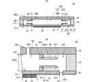
- FIG. 2A is a cross-sectional view showing the configuration of the fluid control device according to the first embodiment
- FIG. 2B is an enlarged cross-sectional view of a portion that realizes a rectifying function.
- 3 (A) and 3 (B) are side sectional views showing the behavior of the central portion of the first main plate and the first film.
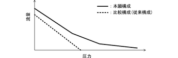
- FIG. 4 is a graph showing the flow rate characteristics of the configuration of the present application and the comparative configuration.
- FIG. 5 is a cross-sectional view showing the configuration of the fluid control device according to the second embodiment.
- FIG. 6 is a cross-sectional view showing the configuration of the fluid control device according to the third embodiment.
- FIG. 7 (A) and 7 (B) are cross-sectional views showing the configuration of the fluid control device according to the fourth embodiment.
- FIG. 8 is a cross-sectional view showing the configuration of the fluid control device according to the fifth embodiment.
- FIG. 9 is a cross-sectional view showing the configuration of the fluid control device according to the sixth embodiment.
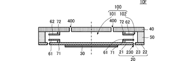
- FIG. 10 is a cross-sectional view showing the configuration of the fluid control device according to the seventh embodiment.
- FIG. 11 is a cross-sectional view showing the configuration of the fluid control device according to the eighth embodiment.
- FIG. 12 is a cross-sectional view showing the configuration of the fluid control device according to the ninth embodiment.
- 13 (A), 13 (B), 13 (C), 13 (D), and 13 (E) are plan views of the first main plate showing the structure of the support portion and its surroundings. ..
- FIG. 1 is an exploded perspective view of the fluid control device according to the first embodiment.
- FIG. 2A is a cross-sectional view showing the configuration of the fluid control device according to the first embodiment.
- FIG. 2B is an enlarged cross-sectional view of a portion that realizes the rectifying function.
- 3 (A) and 3 (B) are side sectional views showing the behavior of the central portion of the first main plate and the first film.
- the shapes of the respective components are exaggerated partially or as a whole in order to make the explanation easy to understand. Further, in order to make the drawings easier to read, the reference numerals are partially omitted for the components that can be uniquely estimated.
- the fluid control device 10 includes a first main plate 20, a piezoelectric element 30, a second main plate 40, a side plate 50, a first film 61, and a second film. 62, a fixing member 71, and a fixing member 72 are provided.
- the first main plate 20 is a flat plate having a circular shape in a plan view.
- the first main plate 20 has a circular first main surface 211 and a second main surface 212.
- the first main surface 211 and the second main surface 212 face each other.
- the first main plate 20 includes a central portion 21, a frame portion 22, a support portion 23, and a first opening 230.
- the central portion 21 has a circular shape in a plan view.
- the frame portion 22 has an annular shape.
- the frame portion 22 surrounds the central portion 21 along the outer circumference of the central portion 21.
- the support portion 23 and the first opening 230 are formed along the outer peripheral end of the central portion 21, and are arranged between the central portion 21 and the frame portion 22.
- the first opening 230 is a groove penetrating between the first main surface 211 and the second main surface 212 of the first main plate 20.
- the support portion 23 connects the outer peripheral end of the central portion 21 and the inner peripheral end of the frame portion 22.
- the support portions 23 are arranged at an angular interval of 90 ° along the outer circumference of the central portion 21.
- the support portion 23 is realized by dividing the groove at a portion along the outer periphery of the first opening 230.
- the central portion 21 can vibrate with respect to the frame portion 22.
- the support portion 23 oscillateably supports the central portion 21 with respect to the frame portion 22.
- the shape of the central portion 21 is preferably circular, but it can also be substantially circular such as an ellipse or polygonal.
- the outer shape of the frame portion 22, that is, the outer shape of the first main plate 20, is not limited to a circular shape, and can be appropriately set according to the design of the outer shape of the fluid control device 10.
- the first main plate 20 is made of, for example, metal or the like.
- the first main plate 20 may have a central portion 21 that causes bending vibration due to distortion of the piezoelectric element 30 described later.
- the bending vibration is a vibration in which the first main surface 211 and the second main surface 212 are displaced in a wavy shape when the central portion 21 is viewed from the side.
- the piezoelectric element 30 includes a disc piezoelectric body and a driving electrode.
- the driving electrodes are formed on both main surfaces of the piezoelectric body of the disk.
- the piezoelectric element 30 is arranged on the second main surface 212 of the central portion 21 of the first main plate 20. At this time, in a plan view, the center of the piezoelectric element 30 and the center of the central portion 21 are substantially coincident with each other.
- the piezoelectric element 30 is distorted by applying a drive signal to the drive electrode. Due to this distortion, the central portion 21 vibrates as described above.
- the second main plate 40 is a flat plate having a circular shape in a plan view.
- the second main plate 40 is preferably made of a material, thickness, etc. that hardly causes bending vibration.
- the outer shape of the second main plate 40 is a size including the outer shape of the first main plate 20.
- the second main plate 40 has a circular third main surface 401 and a fourth main surface 402. The third main surface 401 and the fourth main surface 402 face each other.
- the second main plate 40 includes a plurality of second openings 400.
- the plurality of second openings 400 are tubular through holes penetrating between the third main surface 401 and the fourth main surface 402 of the first main plate 20.
- the plurality of second openings 400 are arranged on the circumference with the center of the second main plate 40 as the origin.
- the second main plate 40 is arranged so that the main surfaces of the second main plate 40 are parallel to each other with respect to the first main plate 20. At this time, the third main surface 401 of the second main plate 40 and the first main surface 211 of the first main plate 20 face each other. Further, the center of the second main plate 40 in a plan view and the center of the first main plate 20 in a plan view are substantially the same.
- the outer shape of the second main plate 40 is not limited to a circular shape, and can be appropriately set according to the design of the outer shape of the fluid control device 10.
- the side plate 50 is an annular pillar body.
- the side plate 50 is preferably made of a material, thickness, etc. that hardly causes bending vibration.
- the side plate 50 may be a separate body from the first main plate 20 or the second main plate 40, or may be integrally formed.
- the side plate 50 is arranged between the first main plate 20 and the second main plate 40.
- One end of the side plate 50 in the height direction is connected to the first main surface 211 of the frame portion 22 of the first main plate 20.
- the other end of the side plate 50 in the height direction is connected to the third main surface 401 of the second main plate 40.
- the fluid control device 10 includes a space surrounded by the first main plate 20, the second main plate 40, and the side plate 50. This space becomes the pump chamber 100 of the fluid control device 10.
- the first film 61 and the second film 62 have an annular shape.
- the first film 61 and the second film 62 are made of a flexible material and are curved in response to an external force.
- the shapes of the first film 61 and the second film 62 are substantially the same.
- the diameter (inner diameter) of the inner ends of the first film 61 and the second film 62 is larger than the diameter of the circle in which the plurality of second openings 400 are arranged. Further, the diameter (outer diameter) of the outer ends of the first film 61 and the second film 62 is smaller than the diameter of the outer circumference of the central portion 21.
- the fixing member 71 and the fixing member 72 have an annular shape.
- the shapes of the fixing member 71 and the fixing member 72 are substantially the same.
- the inner diameters of the fixing member 71 and the fixing member 72 are substantially the same as the inner diameters of the first film 61 and the second film 62.
- the outer diameters of the fixing member 71 and the fixing member 72 are smaller than the outer diameters of the first film 61 and the second film 62.
- the first film 61 is fixed to the first main surface 211 of the first main plate 20 via the fixing member 71.
- the first film 61 is fixed to the central portion 21.
- the center of the first film 61 substantially coincides with the center of the central portion 21.
- the portion of the first film 61 having a predetermined area on the inner end side is fixed to the first main plate 20 via the fixing member 71. Therefore, the portion of the first film 61 on the outer end side that is not connected to the fixing member 71 becomes a movable portion of the first film 61. As a result, the inner end of the first film 61 becomes a fixed end, and the outer end of the first film 61 becomes a movable end.
- the second film 62 is fixed to the third main surface 401 of the second main plate 40 via the fixing member 72.
- the center of the second film 62 substantially coincides with the center of the second main plate 40 (the center of the circle in which the plurality of second openings 400 are arranged).
- the portion of the second film 62 having a predetermined area on the inner end side is fixed to the second main plate 40 via the fixing member 72. Therefore, the portion of the second film 62 on the outer end side that is not connected to the fixing member 72 becomes a movable portion of the second film 62. As a result, the inner end of the second film 62 becomes a fixed end, and the outer end of the second film 62 becomes a movable end.
- the fluid control device 10 includes a first film 61 and a second film 62, each of which has a movable portion, in the pump chamber 100.
- the fluid control device 10 when the fluid control device 10 is viewed in a plan view (viewed in a direction orthogonal to each main surface of the first main plate 20 and the second main plate 40), the arrangement position of the first film 61 and the arrangement position of the second film 62 are obtained. Is almost the same.
- the first film 61 and the second film 62 overlap each other, and the movable portion of the first film 61 and the movable portion of the second film 62 overlap each other. That is, the movable portion of the first film 61 and the movable portion of the second film 62 are arranged so as to face each other.
- the first film 61 and the second film 62 are arranged between the first opening 230 and the second opening 400 in the plan view of the fluid control device 10.
- the pump chamber 100 is divided into a first space 101 that is on the center side of the installation positions of the first film 61 and the second film 62, and a second space 102 that is on the outer peripheral side (side plate 50 side).
- the first space 101 communicates with the second opening 400.
- the second space 102 communicates with the first opening 230.
- the fluid control device 10 when the central portion 21 vibrates, the fluid control device 10 generally repeats the first aspect shown in FIG. 3A and the second aspect shown in FIG. 3B. Behave.
- the fluid flows into the first space 101 from the outside on the second main plate 40 side of the fluid control device 10 through the second opening 400. Further, the fluid tries to flow into the first space 101 from the outside through the first opening 230 and the second space 102.
- the first film 61 and the second film 62 have a movable portion on the outer end side with the inner end as the fixed end.
- the first film 61 is deformed so as to bend toward the second main plate 40 side, that is, the second film 62 side.
- the second film 62 is deformed so as to bend toward the first main plate 20 side, that is, the first film 61 side.
- the movable portion of the first film 61 and the movable portion of the second film 62 come into contact with each other from the outer end side.
- the first space 101 and the second space 102 are blocked (separated). Therefore, the inflow of the fluid from the outside into the first space 101 through the first opening 230 and the second space 102 is suppressed.
- the fluid flows so as to spread between the movable portion of the first film 61 and the movable portion of the second film 62.
- the movable portion of the first film 61 is deformed so as to bend toward the first main plate 20.
- the movable portion of the second film 62 is deformed so as to bend toward the second main plate 40 side.
- the first space 101 and the second space 102 communicate with each other.
- the fluid flows out from the first space 101 to the second space 102, and is discharged from the second space 102 to the outside on the first main surface 211 side of the fluid control device 10 through the first opening 230.
- the opening area of the plurality of first openings 230 is smaller, more preferably sufficiently, as compared with the opening area (side view area) of the space sandwiched between the first film 61 and the second film 62. small. As a result, the fluid in the first space 101 is hardly discharged to the outside from the first opening 230.
- the fluid control device 10 can flow the fluid in one direction. Then, by using the configuration of the fluid control device 10, the fluid does not flow while bending in the rectifying section (arrangement section of the first film 61 and the second film 62), so that a high flow rate characteristic can be realized.
- the fluid control device 10 uses the first film 61 and the second film 62 arranged at positions overlapping each other. As a result, even if the movable amount of the first film 61 and the movable amount of the second film 62 are small, it is possible to shield between the first space 101 and the second space 102. Therefore, the fluid control device 10 can perform the transition between shielding and communication at high speed, and the backflow suppression effect is also improved. As a result, the fluid control device 10 can realize higher flow rate characteristics.
- FIG. 4 is a graph showing the flow rate characteristics between the configuration of the present application and the comparative configuration.
- the horizontal axis is pressure and the vertical axis is flow rate.
- the solid line shows the characteristics of the configuration of the present application
- the broken line shows the characteristics of the comparative configuration.
- the comparative configuration is the configuration of the above-mentioned prior art. As shown in FIG. 4, the flow rate characteristics are improved by using the configuration of the present application.
- the movable portion of the first film 61 and the second film 62 is on the outer peripheral side (side plate 50 side) of the fixed portion.
- the opening area is an area orthogonal to the direction in which the fluid mainly flows, and is an area of a cylindrical surface orthogonal to the first main surface 211 and the third main surface 401. Due to the large opening area, the energy of the fluid when the fluid is conveyed from the first space 101 to the second space 102 (at the time of discharge) becomes small. Therefore, the fluid control device 10 can reduce the energy loss at the time of discharge.
- the movable portion of the first film 61 and the movable portion of the second film 62 overlap on substantially the entire surface.
- the fluid control device 10 can perform the transition between shielding and communication faster and more reliably.
- the fluid control device 10 can realize higher flow rate characteristics. If the movable portion of the first film 61 and the movable portion of the second film 62 overlap at least in part, the effect of improving the flow rate characteristics can be obtained.
- the fluid control device 10 arranges the first film 61 and the second film 62 on the outer peripheral side of the vibration node N21 in the central portion 21.
- the portion of the central portion 21 where the first film 61 is arranged is displaced so as to approach the second main plate 40. Therefore, the first film 61 and the second film 62 are likely to come into contact with each other.
- the portion of the central portion 21 where the first film 61 is arranged is displaced so as to be away from the second main plate 40. Therefore, the distance between the first film 61 and the second film 62 is widened, and the communicating area is increased. As a result, the fluid control device 10 can realize even higher flow rate characteristics.
- the outer end of the first film 61 does not come into contact with the corner portion of the outer end of the central portion 21 formed by the first opening 230. As a result, damage to the first film 61 is suppressed, and the reliability of the fluid control device 10 is improved.
- the shape of the movable portion of the first film 61 and the shape of the movable portion of the second film 62 satisfy the following conditions.
- the length (distance) between the movable end 611, which is the outer end of the first film 61, and the fixed end 612, which is the inner end side and is the end connected to the fixing member 71, is defined as the length L61m.
- the fixed end 612 is an end on the movable portion side when the first film 61 is fixed to the fixing member 71 on a surface.
- the length (distance) between the movable end 621, which is the outer end of the second film 62, and the fixed end 622, which is the inner end side and is the end connected to the fixing member 72 is defined as the length L62m. ..
- the fixed end 622 is an end on the movable portion side when the second film 62 is fixed to the fixing member 72 on a surface.
- the length L61m and the length L62m are substantially the same, and are preferably the same.
- the shape of the movable portion of the first film 61, the shape of the movable portion of the second film 62, and the height of the pump chamber 100 have the following relationship.
- the height of the pump chamber 100 that is, the distance between the first main surface 211 of the first main plate 20 and the third main surface 401 of the second main plate 40 is defined as the height H100.
- the total length of the movable portion length L61 m of the first film 61 and the movable portion length L62 m of the second film 62 is a height H100 or more.
- the total length of the movable portion length L61 m of the first film 61 and the movable portion length L62 m of the second film 62 is substantially the same as the height H100.
- the movable amount of the movable portion of the first film 61 and the movable portion of the second film 62 can be shielded and made smaller. Therefore, the fluid control device 10 can switch each mode of rectification control at higher speed and with lower loss.
- FIG. 5 is a cross-sectional view showing the configuration of the fluid control device according to the second embodiment.
- the fluid control device 10A according to the second embodiment is different from the fluid control device 10 according to the first embodiment in the shape of the central portion 21A of the first main plate 20A.
- the other configuration of the fluid control device 10A is the same as that of the fluid control device 10, and the description of the same parts will be omitted.
- the central portion 21A of the first main plate 20A has a first portion 251 and a second portion 252.
- the thickness of the second portion 252 is larger than the thickness of the first portion 251.
- the difference in thickness of the second portion 252 is realized by the shape of the first portion 251 protruding from the second main surface 212 side.
- the central portion 21A is formed so that the average thickness of the portion inside the vibration node N21 is larger than the average thickness of the portion outside the node N21.
- the piezoelectric element 30 is arranged in the second portion 252.
- the vibration waveform of the central portion 21A (deformed shape of the central portion 21A) can be controlled. More specifically, the displacement near the outer circumference of the central portion 21A due to vibration becomes large. As a result, the deformation of the first film 61 is promoted, and the rectification efficiency of the fluid control device 10A is improved. As a result, the fluid control device 10A can realize even higher flow rate characteristics.
- FIG. 6 is a cross-sectional view showing the configuration of the fluid control device according to the third embodiment.
- the fluid control device 10B according to the third embodiment is different from the fluid control device 10A according to the second embodiment in the configuration of the second main plate 40B.
- Other configurations of the fluid control device 10B are the same as those of the fluid control device 10A, and the description of the same parts will be omitted.
- the second main plate 40B has a recess 411 and a recess 412.
- the recess 411 and the recess 412 have a shape in which the second main plate 40B is recessed with the third main surface 401 side as an opening surface.
- the space formed by the recess 411 is a cylinder, and the space formed by the recess 412 is a ring-shaped column.
- the recess 411 is formed so as to communicate with the first space 101.
- the recess 412 is formed so as to communicate with the second space 102.
- the fluid control device 10B can improve durability and quietness.
- the fluid control device 10C1 and the fluid control device 10C2 according to the fourth embodiment are fluid with respect to the fluid control device 10 according to the first embodiment.
- the positional relationship between the components of the control device and the node N21 is different.
- the other configurations of the fluid control device 10C1 and the fluid control device 10C2 are the same as those of the fluid control device 10, and the description of the same parts will be omitted.
- the node N21 and the second opening 400 overlap each other.
- the fluid control device 10C1 can prevent the fluid in the first space 101 from flowing back to the outside from the second opening 400 when the fluid is discharged.
- the node N21 and the second opening 400 are preferably overlapped with each other, but may be close to each other in a plan view.
- the node N21 and the fixing member 71 overlap each other.
- the node N21 and the fixing member 71 are preferably overlapped with each other, but may be close to each other in a plan view. The position of the node N21 can be detected by a laser displacement meter or the like utilizing the Doppler effect.
- FIG. 8 is a cross-sectional view showing the configuration of the fluid control device according to the fifth embodiment.
- the fluid control device 10D according to the fifth embodiment is different from the fluid control device 10 according to the first embodiment in the fixing mode of the first film 61 and the second film 62.
- Other configurations of the fluid control device 10D are the same as those of the fluid control device 10, and the description of the same parts will be omitted.
- the first film 61 is fixed to the first main plate 20 by the fixing member 71 on the outer end side. That is, in the fluid control device 10D, the outer end side of the first film 61 is a fixed end, and the inner end side is a movable end.
- the second film 62 is fixed to the second main plate 40 by the fixing member 71 on the outer end side. That is, in the fluid control device 10D, the outer end side of the second film 62 is a fixed end, and the inner end side is a movable end.
- the fluid control device 10D can realize a rectifying function and can realize high flow rate characteristics.
- FIG. 9 is a cross-sectional view showing the configuration of the fluid control device according to the sixth embodiment.
- the fluid control device 10E according to the sixth embodiment is different from the fluid control device 10 according to the first embodiment in the positional relationship between the first film 61 and the second film 62. ..
- Other configurations of the fluid control device 10E are the same as those of the fluid control device 10, and the description of the same parts will be omitted.
- the diameter of the fixing member 72 is larger than the diameter of the fixing member 71. Therefore, the fixing member 72 is closer to the side plate 50 than the fixing member 71. As a result, the second film 62 is closer to the side plate 50 than the first film 61. In other words, the second film 62 is closer to the outer periphery of the first main plate 20 and the second main plate 40 than the first film 61.
- the second film 62 and the first film 61 partially overlap each other in a plan view.
- the fluid control device 10E can realize a rectifying function and can realize high flow rate characteristics.
- the length of the movable portion of the first film 61 is larger than the length of the movable portion of the second film 62.
- the fluid control device 10E can more reliably realize the rectifying function and realize higher flow rate characteristics.
- the second film 62 is arranged on the side plate 50 side of the first film 61
- the first film 61 may be arranged on the side plate 50 side of the second film 62. In the case of this configuration, the deformation of the first film 61 is further promoted.
- FIG. 10 is a cross-sectional view showing the configuration of the fluid control device according to the seventh embodiment.
- the fluid control device 10F according to the seventh embodiment is different from the fluid control device 10 according to the first embodiment in the arrangement mode of the first film 61 and the second film 62.
- Other configurations of the fluid control device 10F are the same as those of the fluid control device 10, and the description of the same parts will be omitted.
- the movable end of the first film 61 and the movable end of the second film 62 are arranged outside the outer peripheral end of the first main plate 20 (side plate 50 side). Even with such a configuration, the fluid control device 10F can realize a rectifying function and can realize high flow rate characteristics.
- FIG. 11 is a cross-sectional view showing the configuration of the fluid control device according to the eighth embodiment.
- the upper view in FIG. 11 shows the configuration of the fluid control device, and the lower figure (waveform diagram) shows one aspect of the vibration waveform of the first main plate.
- the fluid control device 10G according to the eighth embodiment is different from the fluid control device 10 according to the first embodiment in which the primary vibration is used in that the secondary vibration is used. ..
- Other configurations of the fluid control device 10G are the same as those of the fluid control device 10, and the description of the same parts will be omitted.
- the central portion 21G of the first main plate 20G vibrates secondarily.
- the secondary vibration can be realized by adjusting the shape and weight of each component constituting the fluid control device 10G such as the first main plate 20G and the driving conditions of the piezoelectric element 30.
- the first film 61 and the second film 62 are arranged on the outer side (side plate 50 side) of the outermost node N21o of the secondary vibration.
- the fluid control device 10G can realize a rectifying function and can realize high flow rate characteristics.
- the first film 61 and the second film 62 may be arranged so that at least the movable end is outside the outermost node N21o of the secondary vibration.
- the secondary vibration has been described as an example, but the same configuration can be applied to vibrations of other orders, and the movable portion of the first film 61 and the movable portion of the first film 61 are located outside the outermost node in the vibration.
- the movable portion of the second film 62 may be arranged.
- FIG. 12 is a cross-sectional view showing the configuration of the fluid control device according to the ninth embodiment.
- the fluid control device 10H according to the ninth embodiment is different from the fluid control device 10 according to the first embodiment in the shapes of the first film 61H and the fixing member 71H.
- Other configurations of the fluid control device 10H are the same as those of the fluid control device 10, and the description of the same parts will be omitted.
- the first film 61H is a circular film.
- the fixing member 71H has a cylindrical shape having a diameter smaller than that of the first film 61.
- the first film 61H is fixed to the first main surface 211 of the central portion 21 by the fixing member 71H on substantially the entire surface of the central portion 21 facing the first space 101. As a result, the fixing strength of the first film 61H with respect to the central portion 21 can be increased.
- the fluid control device 10H can realize a rectifying function and can realize high flow rate characteristics.
- the first film 61H is less likely to come off, and the reliability of the fluid control device 10H is improved.
- the configuration shown in E) can be adopted.
- 13 (A), 13 (B), 13 (C), 13 (D), and 13 (E) are plan views of the first main plate showing the structure of the support portion and its surroundings. ..
- the first main plate 20 shown in FIG. 13A has the configuration shown in FIG. 1 described above, but the support portion 23 has a first portion connected to the central portion 21 and a second portion connected to the frame portion 22. It also has a third portion that connects the first portion and the second portion.
- the first portion and the second portion have a shape extending along a direction connecting the outer peripheral end of the central portion 21 and the frame portion at the shortest distance.
- the two second portions are arranged symmetrically with respect to an axis along the extending direction of the first portion.
- the third portion has a shape extending along the outer circumference of the central portion 21. Both ends of the third portion in the extending direction are connected to the two second portions.
- the intermediate position in the extending direction of the third portion connects to the first portion.
- the first main plate 20DE1 shown in FIG. 13 (B) is different from the first main plate 20 shown in FIG. 13 (A) in the shape of the frame portion 22.
- the frame portion 22 has a notch portion 220 between the connecting portions of the support portion 23 and the two second portions.
- the position of the notch portion 220 may be another portion of the frame portion 22 as long as it is not a portion connected to the second portion of the support portion 23.
- the first main plate 20DE2 shown in FIG. 13C is different from the first main plate 20 shown in FIG. 13A in the shape of the support portion 23DE2.
- the support portion 23DE2 has a configuration in which one second portion is omitted from the support portion 23.
- the first main plate 20DE3 shown in FIG. 13D is different from the first main plate 20 shown in FIG. 13A in the shapes of the first opening 230DE3 and the support portion 23DE3.
- the first opening 230DE3 is realized by two grooves having different diameters.
- the two grooves penetrate the first main plate 20 along the thickness direction. That is, the two grooves communicate the first main surface 211 side and the second main surface 212 side.
- Each of the two grooves is divided into a plurality of grooves at a plurality of points on the circumference. The dividing position in the inner groove and the dividing position in the outer groove are different.
- the support portion 23DE3 is formed by the divided portions of the two grooves.
- the first main plate 20DE4 shown in FIG. 13 (E) differs from the first main plate 20 shown in FIG. 13 (A) in the shapes of the first opening 230DE4 and the support portion 23DE4.
- the first opening 230DE4 is realized by a plurality of through holes arranged on the circumference.
- the support portion 23DE4 is formed by the portion between the plurality of through holes.
- this configuration includes the configuration of the present invention. It has the same effect as the present invention.
Landscapes
- Engineering & Computer Science (AREA)
- Mechanical Engineering (AREA)
- General Engineering & Computer Science (AREA)
- Reciprocating Pumps (AREA)
Abstract
Description
本発明の第1の実施形態に係る流体制御装置について、図を参照して説明する。図1は、第1の実施形態に係る流体制御装置の分解斜視図である。図2(A)は、第1の実施形態に係る流体制御装置の構成を示す断面図である。図2(B)は、整流機能を実現する部分の拡大断面図である。図3(A)、図3(B)は、第1主板の中央部および第1フィルムの挙動を示す側面断面図である。なお、以下の各実施形態に示す各図においては、説明を分かり易くするために、それぞれの構成要素の形状を部分的または全体として誇張して記載している。また、図面を読み易くするために、一意的に推定できる構成要素については、部分的に符号を省略している。 (First Embodiment)
The fluid control device according to the first embodiment of the present invention will be described with reference to the drawings. FIG. 1 is an exploded perspective view of the fluid control device according to the first embodiment. FIG. 2A is a cross-sectional view showing the configuration of the fluid control device according to the first embodiment. FIG. 2B is an enlarged cross-sectional view of a portion that realizes the rectifying function. 3 (A) and 3 (B) are side sectional views showing the behavior of the central portion of the first main plate and the first film. In each of the figures shown in the following embodiments, the shapes of the respective components are exaggerated partially or as a whole in order to make the explanation easy to understand. Further, in order to make the drawings easier to read, the reference numerals are partially omitted for the components that can be uniquely estimated.
図1、図2(A)、図2(B)に示すように、流体制御装置10は、第1主板20、圧電素子30、第2主板40、側板50、第1フィルム61、第2フィルム62、固定部材71、および、固定部材72を備える。 (Structure of fluid control device 10)
As shown in FIGS. 1, 2 (A) and 2 (B), the
上述の構成において、中央部21が振動すると、概略的には、流体制御装置10は、図3(A)に示す第1態様と、図3(B)に示す第2態様とを繰り返すように挙動する。 (Specific explanation of rectification function)
In the above configuration, when the
図3(A)に示す第1態様では、中央部21のノードN21よりも中央側の部分は、第2主板40から遠ざかるように変位する。一方、中央部21のノードN21よりも外周側の部分は、第2主板40に近づくように変位する。これにより、中央部21の中央側の第1空間101は、流体制御装置10の外部および第2空間102に対して低圧(負圧)になる。 1. 1. Inflow of fluid from the outside into the pump chamber In the first aspect shown in FIG. 3A, the portion of the
図3(B)に示す第2態様では、中央部21のノードN21よりも中央側の部分は、第2主板40に近づくように変位する。一方、中央部21のノードN21よりも外周側の部分は、第2主板40から遠ざかるように変位する。これにより、中央部21の中央側の第1空間101は、第2空間102に対して高圧(正圧)になる。 2. 2. Discharge of fluid from the pump chamber to the outside In the second aspect shown in FIG. 3B, the portion of the
第2の実施形態に係る流体制御装置について、図を参照して説明する。図5は、第2の実施形態に係る流体制御装置の構成を示す断面図である。 (Second Embodiment)
The fluid control device according to the second embodiment will be described with reference to the drawings. FIG. 5 is a cross-sectional view showing the configuration of the fluid control device according to the second embodiment.
第3の実施形態に係る流体制御装置について、図を参照して説明する。図6は、第3の実施形態に係る流体制御装置の構成を示す断面図である。 (Third Embodiment)
The fluid control device according to the third embodiment will be described with reference to the drawings. FIG. 6 is a cross-sectional view showing the configuration of the fluid control device according to the third embodiment.
第4の実施形態に係る流体制御装置について、図を参照して説明する。図7(A)、図7(B)は、第4の実施形態に係る流体制御装置の構成を示す断面図である。 (Fourth Embodiment)
The fluid control device according to the fourth embodiment will be described with reference to the drawings. 7 (A) and 7 (B) are cross-sectional views showing the configuration of the fluid control device according to the fourth embodiment.
第5の実施形態に係る流体制御装置について、図を参照して説明する。図8は、第5の実施形態に係る流体制御装置の構成を示す断面図である。 (Fifth Embodiment)
The fluid control device according to the fifth embodiment will be described with reference to the drawings. FIG. 8 is a cross-sectional view showing the configuration of the fluid control device according to the fifth embodiment.
第6の実施形態に係る流体制御装置について、図を参照して説明する。図9は、第6の実施形態に係る流体制御装置の構成を示す断面図である。 (Sixth Embodiment)
The fluid control device according to the sixth embodiment will be described with reference to the drawings. FIG. 9 is a cross-sectional view showing the configuration of the fluid control device according to the sixth embodiment.
第7の実施形態に係る流体制御装置について、図を参照して説明する。図10は、第7の実施形態に係る流体制御装置の構成を示す断面図である。 (7th Embodiment)
The fluid control device according to the seventh embodiment will be described with reference to the drawings. FIG. 10 is a cross-sectional view showing the configuration of the fluid control device according to the seventh embodiment.
第8の実施形態に係る流体制御装置について、図を参照して説明する。図11は、第8の実施形態に係る流体制御装置の構成を示す断面図である。図11における上側の図は、流体制御装置の構成を示し、下側の図(波形図)は、第1主板の振動波形の一態様を示している。 (8th Embodiment)
The fluid control device according to the eighth embodiment will be described with reference to the drawings. FIG. 11 is a cross-sectional view showing the configuration of the fluid control device according to the eighth embodiment. The upper view in FIG. 11 shows the configuration of the fluid control device, and the lower figure (waveform diagram) shows one aspect of the vibration waveform of the first main plate.
第9の実施形態に係る流体制御装置について、図を参照して説明する。図12は、第9の実施形態に係る流体制御装置の構成を示す断面図である。 (9th embodiment)
The fluid control device according to the ninth embodiment will be described with reference to the drawings. FIG. 12 is a cross-sectional view showing the configuration of the fluid control device according to the ninth embodiment.
上述の説明では、支持部の形状を詳細には記載していないが、例えば、図13(A)、図13(B)、図13(C)、図13(D)、および、図13(E)に示すような構成を採用できる。図13(A)、図13(B)、図13(C)、図13(D)、および、図13(E)は、支持部およびその周辺の構造を示す第1主板の平面図である。 (Specific shape example of the support part)
Although the shape of the support portion is not described in detail in the above description, for example, FIGS. 13 (A), 13 (B), 13 (C), 13 (D), and 13 (D). The configuration shown in E) can be adopted. 13 (A), 13 (B), 13 (C), 13 (D), and 13 (E) are plan views of the first main plate showing the structure of the support portion and its surroundings. ..
20、20A、20DE1、20DE2、20DE3、20DE4、20G、20G:第1主板
21、21A、21G:中央部
22:枠部
23、23DE2、23DE3、23DE4:支持部
30:圧電素子
40、40B:第2主板
50:側板
61、61H:第1フィルム
62:第2フィルム
71、71H、72:固定部材
100:ポンプ室
101:第1空間
102:第2空間
211:第1主面
212:第2主面
230、230DE3、230DE4:第1開口
251:第1部分
252:第2部分
400:第2開口
401:第3主面
402:第4主面
411、412:凹部
611、621:可動端
612、622:固定端
N21、N21o:ノード 10, 10A, 10B, 10C1, 10C2, 10D, 10E, 10F, 10G, 10H:
Claims (11)
- 第1主面と第2主面とを有する第1主板と、
第3主面と第4主面とを有し、前記第3主面が前記第1主面に対向する第2主板と、
前記第1主板と前記第2主板とを接続する側板と、
前記第1主板、前記第2主板、および、前記側板によって囲まれるポンプ室と、
を備え、
前記第1主板は、中央部と、前記中央部の外周に配置された枠部と、前記枠部と前記中央部とに接続し前記中央部を振動可能に支持する支持部と、前記中央部と前記枠部との間に形成され、前記ポンプ室と前記第2主面側の外部とを連通する第1開口と、を備え、
前記第2主板は、前記ポンプ室と前記第4主面側の外部とを連通する第2開口を備え、
前記中央部に配置され、前記中央部を振動させる圧電素子と、
一方端が可動端となる可動部を有するよう前記第1主面に配置された第1フィルムと、
一方端が可動端となる可動部を有するよう前記第3主面に配置された第2フィルムと、
を備え、
前記第1フィルムと前記第2フィルムとは、前記第1開口と前記第2開口との間に配置されている、
流体制御装置。 A first main plate having a first main surface and a second main surface,
A second main plate having a third main surface and a fourth main surface, and the third main surface facing the first main surface.
A side plate connecting the first main plate and the second main plate,
A pump chamber surrounded by the first main plate, the second main plate, and the side plates.
With
The first main plate includes a central portion, a frame portion arranged on the outer periphery of the central portion, a support portion connected to the frame portion and the central portion to vibrately support the central portion, and the central portion. It is provided with a first opening formed between the frame portion and the frame portion and communicating the pump chamber with the outside of the second main surface side.
The second main plate includes a second opening that communicates the pump chamber with the outside of the fourth main surface side.
A piezoelectric element that is arranged in the central portion and vibrates the central portion,
A first film arranged on the first main surface so as to have a movable portion whose one end is a movable end,
A second film arranged on the third main surface so as to have a movable portion whose one end is a movable end,
With
The first film and the second film are arranged between the first opening and the second opening.
Fluid control device. - 各主面に直交する方向に視て、前記第1フィルムの可動部と前記第2フィルムの可動部とは、重なっている、
請求項1に記載の流体制御装置。 When viewed in a direction orthogonal to each main surface, the movable portion of the first film and the movable portion of the second film overlap each other.
The fluid control device according to claim 1. - 前記第1フィルムの可動部の固定端と可動端との間の長さと、前記第2フィルムの可動部の固定端と可動端との間の長さとは、略同じである、
請求項1または請求項2に記載の流体制御装置。 The length between the fixed end and the movable end of the movable portion of the first film and the length between the fixed end and the movable end of the movable portion of the second film are substantially the same.
The fluid control device according to claim 1 or 2. - 前記第1フィルムの固定端は、前記第1フィルムの可動部の内端であり、
前記第2フィルムの固定端は、前記第2フィルムの可動部の内端である、
請求項1乃至請求項3のいずれかに記載の流体制御装置。 The fixed end of the first film is the inner end of the movable portion of the first film.
The fixed end of the second film is the inner end of the movable portion of the second film.
The fluid control device according to any one of claims 1 to 3. - 前記第1フィルムの可動端および前記第2フィルムの可動端は、前記中央部の振動の最も外周側の節よりも、前記側板側にある、
請求項4に記載の流体制御装置。 The movable end of the first film and the movable end of the second film are closer to the side plate than the outermost node of the vibration in the central portion.
The fluid control device according to claim 4. - 前記第1フィルムの可動端および前記第2フィルムの可動端は、前記第1開口よりも平面視して内側にある、
請求項5に記載の流体制御装置。 The movable end of the first film and the movable end of the second film are inside the first opening in a plan view.
The fluid control device according to claim 5. - 前記第1フィルムの固定端は、前記第1フィルムの可動部の外端であり、
前記第2フィルムの固定端は、前記第2フィルムの可動部の外端である、
請求項1乃至請求項3のいずれかに記載の流体制御装置。 The fixed end of the first film is the outer end of the movable portion of the first film.
The fixed end of the second film is the outer end of the movable portion of the second film.
The fluid control device according to any one of claims 1 to 3. - 前記第1フィルムの可動部の固定端と可動端との間の長さと、前記第2フィルムの可動部の固定端と可動端との間の長さとを加算した長さは、前記第1主面と前記第3主面との距離以上である、
請求項1乃至請求項7のいずれかに記載の流体制御装置。 The total length of the length between the fixed end and the movable end of the movable portion of the first film and the length between the fixed end and the movable end of the movable portion of the second film is the first main. It is equal to or greater than the distance between the surface and the third main surface.
The fluid control device according to any one of claims 1 to 7. - 前記第1フィルムの可動部の固定端と可動端との間の長さと、前記第2フィルムの可動部の固定端と可動端との間の長さとを加算した長さは、前記第1主面と前記第3主面との距離と略同じである、
請求項8に記載の流体制御装置。 The total length of the length between the fixed end and the movable end of the movable portion of the first film and the length between the fixed end and the movable end of the movable portion of the second film is the first main. The distance between the surface and the third main surface is approximately the same,
The fluid control device according to claim 8. - 前記中央部における最も外周に近い振動の節よりも中央側の部分の平均厚みは、前記中央部における前記最も外周に近い節よりも外周側の部分の平均厚みよりも大きい、
請求項1乃至請求項9のいずれかに記載の流体制御装置。 The average thickness of the portion on the central side of the vibration node closest to the outer circumference in the central portion is larger than the average thickness of the portion on the outer peripheral side of the node closest to the outer circumference in the central portion.
The fluid control device according to any one of claims 1 to 9. - 前記支持部は、前記中央部と前記枠部との間に複数備えられており、
前記第1開口は、前記中央部と前記枠部との間の部分における、前記複数の支持部の間にある、
請求項1乃至請求項10のいずれかに記載の流体制御装置。 A plurality of the support portions are provided between the central portion and the frame portion.
The first opening is between the plurality of support portions in a portion between the central portion and the frame portion.
The fluid control device according to any one of claims 1 to 10.
Priority Applications (4)
| Application Number | Priority Date | Filing Date | Title |
|---|---|---|---|
| GB2118672.1A GB2599820B (en) | 2019-07-03 | 2020-05-14 | Fluid control apparatus |
| CN202080048399.4A CN114127421B (en) | 2019-07-03 | 2020-05-14 | Fluid control device |
| JP2021529905A JP7243830B2 (en) | 2019-07-03 | 2020-05-14 | Fluid control device |
| US17/646,497 US20220120268A1 (en) | 2019-07-03 | 2021-12-30 | Fluid control apparatus |
Applications Claiming Priority (2)
| Application Number | Priority Date | Filing Date | Title |
|---|---|---|---|
| JP2019124101 | 2019-07-03 | ||
| JP2019-124101 | 2019-07-03 |
Related Child Applications (1)
| Application Number | Title | Priority Date | Filing Date |
|---|---|---|---|
| US17/646,497 Continuation US20220120268A1 (en) | 2019-07-03 | 2021-12-30 | Fluid control apparatus |
Publications (1)
| Publication Number | Publication Date |
|---|---|
| WO2021002101A1 true WO2021002101A1 (en) | 2021-01-07 |
Family
ID=74101001
Family Applications (1)
| Application Number | Title | Priority Date | Filing Date |
|---|---|---|---|
| PCT/JP2020/019176 WO2021002101A1 (en) | 2019-07-03 | 2020-05-14 | Fluid control device |
Country Status (5)
| Country | Link |
|---|---|
| US (1) | US20220120268A1 (en) |
| JP (1) | JP7243830B2 (en) |
| CN (1) | CN114127421B (en) |
| GB (1) | GB2599820B (en) |
| WO (1) | WO2021002101A1 (en) |
Citations (3)
| Publication number | Priority date | Publication date | Assignee | Title |
|---|---|---|---|---|
| CN201057136Y (en) * | 2007-05-25 | 2008-05-07 | 吉林大学 | Active valve type piezoelectric pump of piezoelectric vibrator |
| JP2008527232A (en) * | 2004-12-30 | 2008-07-24 | アダプティブエナジー・リミテッド・ライアビリティー・カンパニー | Active valve and active valve control for pump |
| WO2016013390A1 (en) * | 2014-07-25 | 2016-01-28 | 株式会社村田製作所 | Fluid control device |
Family Cites Families (8)
| Publication number | Priority date | Publication date | Assignee | Title |
|---|---|---|---|---|
| US20090182261A1 (en) * | 2008-01-11 | 2009-07-16 | Seiko Epson Corporation | Fluid Ejecting Apparatus, Surgical Operation Instrument |
| CN101520038B (en) * | 2008-02-26 | 2011-07-20 | 研能科技股份有限公司 | Micro-droplet fluid conveying device |
| JP5309786B2 (en) * | 2008-08-21 | 2013-10-09 | 株式会社リコー | Microvalve, micropump, and manufacturing method of microvalve |
| JP2010216398A (en) * | 2009-03-17 | 2010-09-30 | Tdk Corp | Piezoelectric pump |
| US20140248170A1 (en) * | 2011-09-27 | 2014-09-04 | Kikuchiseisakusho Co., Ltd. | Microdiaphragm pump |
| DE102015215738A1 (en) * | 2015-08-18 | 2017-02-23 | Continental Reifen Deutschland Gmbh | Vehicle tires |
| JP6912004B2 (en) * | 2018-05-31 | 2021-07-28 | 株式会社村田製作所 | Fluid control device |
| WO2021171917A1 (en) * | 2020-02-26 | 2021-09-02 | 株式会社村田製作所 | Fluid control device |
-
2020
- 2020-05-14 WO PCT/JP2020/019176 patent/WO2021002101A1/en active Application Filing
- 2020-05-14 CN CN202080048399.4A patent/CN114127421B/en active Active
- 2020-05-14 JP JP2021529905A patent/JP7243830B2/en active Active
- 2020-05-14 GB GB2118672.1A patent/GB2599820B/en active Active
-
2021
- 2021-12-30 US US17/646,497 patent/US20220120268A1/en active Pending
Patent Citations (3)
| Publication number | Priority date | Publication date | Assignee | Title |
|---|---|---|---|---|
| JP2008527232A (en) * | 2004-12-30 | 2008-07-24 | アダプティブエナジー・リミテッド・ライアビリティー・カンパニー | Active valve and active valve control for pump |
| CN201057136Y (en) * | 2007-05-25 | 2008-05-07 | 吉林大学 | Active valve type piezoelectric pump of piezoelectric vibrator |
| WO2016013390A1 (en) * | 2014-07-25 | 2016-01-28 | 株式会社村田製作所 | Fluid control device |
Also Published As
| Publication number | Publication date |
|---|---|
| CN114127421B (en) | 2023-07-07 |
| US20220120268A1 (en) | 2022-04-21 |
| GB2599820A (en) | 2022-04-13 |
| JPWO2021002101A1 (en) | 2021-01-07 |
| JP7243830B2 (en) | 2023-03-22 |
| GB2599820B (en) | 2023-04-26 |
| CN114127421A (en) | 2022-03-01 |
Similar Documents
| Publication | Publication Date | Title |
|---|---|---|
| US11725646B2 (en) | Fluid control device | |
| US11293428B2 (en) | Pump and fluid control device | |
| US20220381361A1 (en) | Fluid control device | |
| JP5966383B2 (en) | Lens drive device | |
| US20230313790A1 (en) | Fluid control device | |
| WO2021002101A1 (en) | Fluid control device | |
| JP2005077326A (en) | Vibration sensor | |
| WO2021002100A1 (en) | Fluid control device | |
| WO2022070549A1 (en) | Fluid control device | |
| JPWO2020111063A1 (en) | pump | |
| US11300115B2 (en) | Pump and fluid control device | |
| US11566615B2 (en) | Pump and fluid control apparatus | |
| WO2021106301A1 (en) | Actuator and fluid control device | |
| US20230140980A1 (en) | Fluid control device | |
| WO2024135219A1 (en) | Fluid control device | |
| JPWO2021002101A5 (en) | ||
| JP7364078B2 (en) | Actuator and fluid control device |
Legal Events
| Date | Code | Title | Description |
|---|---|---|---|
| 121 | Ep: the epo has been informed by wipo that ep was designated in this application |
Ref document number: 20834942 Country of ref document: EP Kind code of ref document: A1 |
|
| ENP | Entry into the national phase |
Ref document number: 202118672 Country of ref document: GB Kind code of ref document: A Free format text: PCT FILING DATE = 20200514 |
|
| ENP | Entry into the national phase |
Ref document number: 2021529905 Country of ref document: JP Kind code of ref document: A |
|
| NENP | Non-entry into the national phase |
Ref country code: DE |
|
| 122 | Ep: pct application non-entry in european phase |
Ref document number: 20834942 Country of ref document: EP Kind code of ref document: A1 |