WO2021001925A1 - Outdoor unit of air conditioner - Google Patents
Outdoor unit of air conditioner Download PDFInfo
- Publication number
- WO2021001925A1 WO2021001925A1 PCT/JP2019/026302 JP2019026302W WO2021001925A1 WO 2021001925 A1 WO2021001925 A1 WO 2021001925A1 JP 2019026302 W JP2019026302 W JP 2019026302W WO 2021001925 A1 WO2021001925 A1 WO 2021001925A1
- Authority
- WO
- WIPO (PCT)
- Prior art keywords
- soundproofing material
- outdoor unit
- compressor
- soundproofing
- surface portion
- Prior art date
Links
Images


Classifications
-
- F—MECHANICAL ENGINEERING; LIGHTING; HEATING; WEAPONS; BLASTING
- F24—HEATING; RANGES; VENTILATING
- F24F—AIR-CONDITIONING; AIR-HUMIDIFICATION; VENTILATION; USE OF AIR CURRENTS FOR SCREENING
- F24F1/00—Room units for air-conditioning, e.g. separate or self-contained units or units receiving primary air from a central station
- F24F1/06—Separate outdoor units, e.g. outdoor unit to be linked to a separate room comprising a compressor and a heat exchanger
- F24F1/40—Vibration or noise prevention at outdoor units
Definitions
- the present invention relates to an outdoor unit of an air conditioner that reduces noise.
- the outdoor unit of an air conditioner is provided with an outer shell portion and a partition plate for partitioning the inside of the outer shell portion.
- a machine room is formed by a part of the outer shell and a partition plate.
- a compressor is housed in this machine room.
- the conventional outdoor unit is provided with a soundproofing material that surrounds the outer peripheral portion of the compressor.
- noise may leak from the soundproofing material that surrounds the outer periphery of the compressor.
- the noise leaking from the soundproofing material surrounding the outer peripheral portion of the compressor is, for example, the noise transmitted to the outside of the soundproofing material through the gap of the soundproofing material.
- the noise leaking from the soundproof material surrounding the outer peripheral portion of the compressor is generated when the compressor or the refrigerant pipe connected to the compressor comes into contact with the soundproof material and the vibration of the compressor is transmitted to the soundproof material. It's noise.
- a soundproofing material is provided at a portion constituting the machine room on the back surface of the outer shell, and noise leaked from the soundproofing material surrounding the outer peripheral portion of the compressor is emitted from the outdoor unit.
- a device that suppresses leakage to the outside has also been proposed (see Patent Document 1).
- the noise leaked from the soundproofing material that surrounds the outer periphery of the compressor is reflected by the partition plate that forms part of the machine room and propagates in a specific direction.
- the noise of the outdoor unit increases in the direction in which the noise reflected by the partition plate propagates. In order to suppress this noise, it is necessary to disperse the direction in which this noise propagates.
- the conventional outdoor unit which aims to suppress the noise leaked from the soundproofing material surrounding the outer peripheral portion of the compressor from leaking to the outside of the outdoor unit, it is provided outside the soundproofing material surrounding the outer peripheral portion of the compressor.
- the soundproofing material is provided on the back surface of the outer shell.
- the position of the soundproofing material provided on the back surface of the outer shell portion is far from the position where the noise leaked from the soundproofing material surrounding the outer peripheral portion of the compressor is reflected by the partition plate.
- the conventional outdoor unit which is designed to prevent the noise leaked from the soundproofing material surrounding the outer peripheral portion of the compressor from leaking to the outside of the outdoor unit, transmits the noise reflected by the partition plate and propagated in a specific direction. It cannot be sufficiently dispersed by the soundproofing material provided on the back surface of the outer shell.
- the present invention has been made to solve the above-mentioned problems, and an object of the present invention is to obtain an outdoor unit of an air conditioner capable of suppressing noise of an outdoor unit more than before.
- the outdoor unit of the air conditioner according to the present invention includes an outer shell portion, a partition plate for partitioning the inside of the outer shell portion, a compressor, and a first soundproofing material surrounding the outer peripheral portion of the compressor.
- a machine room is formed by a part of a portion and the partition plate, and the outdoor unit of an air conditioner in which the compressor is housed in the machine room, which is a plate-shaped second extending in the machine room in the vertical direction.
- a soundproofing material is further provided, and the second soundproofing material is provided with a non-woven fabric on the surface on the compressor side, and a portion of the outer shell portion constituting the front portion of the machine room is designated as the first front surface portion.
- the second soundproofing material is the first soundproofing material, the said.
- the first soundproofing material, the first front surface portion, the first side surface portion and the first back surface portion so as not to touch the first front surface portion, the first side surface portion and the first back surface portion. It is located in an enclosed space.
- the second soundproofing material provided outside the first soundproofing material surrounding the outer peripheral portion of the compressor is provided outside the soundproofing material surrounding the outer peripheral portion of the compressor.
- the noise leaked from the first soundproofing material is arranged at a position closer to the position where it is reflected on the partition plate. Therefore, in the outdoor unit of the air conditioner according to the present invention, the noise reflected by the partition plate and propagated in a specific direction can be dispersed by the second soundproofing material. Therefore, the outdoor unit according to the present invention can suppress the noise of the outdoor unit more than before.
- FIG. FIG. 5 is a perspective view of the outdoor unit according to the first embodiment as viewed from the front right side. It is a perspective view which looked at the outdoor unit which concerns on Embodiment 1 from the front right side, and is the figure which showed the state which the top surface part, the front part part, the left side side part part, the right side side part, and the back part of the outer shell part were removed. is there. It is a figure which observed the periphery of the compressor of the outdoor unit which concerns on Embodiment 1 from the side. It is a figure which observed the cross section of the machine room of the outdoor unit which concerns on Embodiment 1 from above.
- FIG. 1 It is a figure which observed the cross section of the machine room of the outdoor unit which concerns on Embodiment 2 from above. It is a figure which looked at the 2nd soundproofing material which concerns on Embodiment 3 from the side. It is a vertical sectional view of the 2nd soundproofing material which concerns on Embodiment 4.
- FIG. 1 It is a figure which observed the cross section of the machine room of the outdoor unit which concerns on Embodiment 2 from above. It is a figure which looked at the 2nd soundproofing material which concerns on Embodiment 3 from the side. It is a vertical sectional view of the 2nd soundproofing material which concerns on Embodiment 4.
- FIG. 1 is a refrigerant circuit diagram of an air conditioner in which the outdoor unit according to the first embodiment is used.
- the air conditioner 1 in which the outdoor unit 2 according to the first embodiment is used includes a refrigeration cycle circuit 10.
- the refrigeration cycle circuit 10 is configured by connecting a compressor 40, a four-way switching valve 11, an outdoor heat exchanger 12, an indoor heat exchanger 13, an expansion valve 14, and an expansion valve 15 with a refrigerant pipe.
- the type of refrigerant circulating in the refrigeration cycle circuit 10 is not limited.
- Various refrigerants such as R410A, R32, water and CO 2 can be used as the refrigerant circulating in the refrigeration cycle circuit 10.
- the compressor 40 compresses the refrigerant.
- the compressor 40 includes a main body 41 having a compression mechanism for compressing the refrigerant. Further, the main body 41 includes a container 42 which is a closed container. The compression mechanism unit is housed in the container 42. Further, the compressor 40 includes a suction muffler 43 which is a closed container. The suction muffler 43 separates the refrigerant flowing into the suction muffler 43 into a gaseous refrigerant and a liquid refrigerant. The refrigerant outlet of the suction muffler 43 is connected to the refrigerant inlet of the main body 41. Then, the gaseous refrigerant is supplied from the suction muffler 43 to the main body 41.
- This gaseous refrigerant is compressed by the compression mechanism of the main body 41 and then discharged from the main body 41. That is, the inflow port of the refrigerant of the suction muffler 43 is the suction port of the refrigerant of the compressor 40. Further, the outlet of the refrigerant of the main body 41, in other words, the outlet of the refrigerant of the container 42 is the discharge port of the refrigerant of the compressor 40.
- the refrigerant pipe connected to the refrigerant suction port of the compressor 40 will be referred to as the suction pipe 18.
- the suction pipe 18 is connected to the upper part of the suction muffler 43.
- the refrigerant pipe connected to the refrigerant discharge port of the compressor 40 will be referred to as a discharge pipe 19.
- the discharge pipe 19 is connected to the upper part of the container 42.
- the four-way switching valve 11 is connected to the refrigerant suction port of the compressor 40, the refrigerant discharge port of the compressor 40, the outdoor heat exchanger 12, and the indoor heat exchanger 13.
- the four-way switching valve 11 switches the connection destination of the refrigerant discharge port of the compressor 40 to the outdoor heat exchanger 12 or the indoor heat exchanger 13. In other words, the four-way switching valve 11 switches the connection destination of the refrigerant suction port of the compressor 40 to the outdoor heat exchanger 12 or the indoor heat exchanger 13.
- the outdoor heat exchanger 12 functions as an evaporator during the heating operation and as a condenser during the cooling operation.
- the fan 21 is provided in the vicinity of the outdoor heat exchanger 12.
- the fan 21 supplies the outdoor heat exchanger 12 with outdoor air that is a heat exchange target of the refrigerant flowing through the outdoor heat exchanger 12.
- the fan 21 is driven by a motor 22.
- the indoor heat exchanger 13 functions as a condenser during the heating operation and as an evaporator during the cooling operation.
- the expansion valve 14 is provided in the refrigerant pipe connecting the outdoor heat exchanger 12 and the indoor heat exchanger 13, and regulates the flow rate of the refrigerant flowing through the outdoor heat exchanger 12.
- the expansion valve 15 is provided at a position closer to the indoor heat exchanger 13 than the expansion valve 14 in the refrigerant pipe connecting the outdoor heat exchanger 12 and the indoor heat exchanger 13, and flows through the indoor heat exchanger 13. Adjust the flow rate of the refrigerant.
- the air conditioner 1 is provided with various sensors and a control device 38.
- the pressure sensor 31 detects the pressure of the refrigerant discharged from the compressor 40.
- the pressure sensor 32 detects the pressure of the refrigerant sucked into the compressor 40.
- the temperature sensor 33 detects the temperature of the outdoor air supplied to the outdoor heat exchanger 12.
- the temperature sensor 34 detects the temperature of the refrigerant flowing through the outdoor heat exchanger 12.
- the temperature sensor 35 detects the temperature of the refrigerant flowing between the expansion valve 15 and the indoor heat exchanger 13.
- the temperature sensor 36 detects the temperature of the refrigerant flowing through the indoor heat exchanger 13.
- the temperature sensor 37 detects the temperature of the indoor air supplied to the indoor heat exchanger 13.
- the control device 38 controls the drive frequency of the compression mechanism of the compressor 40, the rotation speed of the fan 21, the opening degree of the expansion valve 14, the opening degree of the expansion valve 15, and the like based on the detected values of these sensors. ..
- the outdoor unit 2 includes a four-way switching valve 11, an outdoor heat exchanger 12, an expansion valve 14, a fan 21, a motor 22, a pressure sensor 31, a pressure sensor 32, a temperature sensor 33, a temperature sensor 34, and a control device. 38 and the compressor 40 are housed in it.
- the indoor unit 3 houses an indoor heat exchanger 13, an expansion valve 15, a temperature sensor 35, a temperature sensor 36, and a temperature sensor 37. Further, in the air conditioner 1 according to the first embodiment, the refrigerant pipe connecting the configuration of the refrigeration cycle circuit 10 provided in the outdoor unit 2 and the configuration of the refrigeration cycle circuit 10 provided in the indoor unit 3 is connected.
- An on-off valve 16 and an on-off valve 17 are provided.
- the on-off valve 16 and the on-off valve 17 are housed in the outdoor unit 2.
- the air conditioner 1 according to the first embodiment includes two indoor units 3. These indoor units 3 are connected to the outdoor unit 2 in parallel.
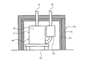
- FIG. 2 is a perspective view of the outdoor unit according to the first embodiment as viewed from the front right side.
- FIG. 3 is a perspective view of the outdoor unit according to the first embodiment as viewed from the front right side, and shows the outdoor unit in a state where the top surface portion, the front surface portion, the left side surface portion, the right side surface portion, and the back surface portion of the outer shell portion are removed. It is a figure shown.
- the outdoor unit 2 includes, for example, an outer shell portion 50 having a substantially rectangular parallelepiped shape. Further, the outer shell portion 50 is provided with a plurality of handles 59 that the operator grips when moving the outdoor unit 2.
- the method of configuring the outer shell portion 50 is not particularly limited, but in the first embodiment, the top panel 51, the base 52, the front panel 53, the service panel 54, the right side panel 55, the left side panel 56, the cover panel 57, and the like.
- the cover panel 58 constitutes the outer shell portion 50.
- the top panel 51 constitutes the top of the outer shell 50.
- the base 52 constitutes a bottom surface portion of the outer shell portion 50.
- the front panel 53 constitutes a left side portion of the front surface portion of the outer shell portion 50.
- the service panel 54 constitutes an upper portion on the right side of the front surface portion of the outer shell portion 50 and an upper portion on the front side of the right side surface portion of the outer shell portion 50.
- the right side panel 55 constitutes an upper portion on the rear side of the right side surface portion of the outer shell portion 50 and an upper portion on the right side of the back surface portion of the outer shell portion 50.
- the left side panel 56 constitutes the left side surface of the outer shell 50.
- the cover panel 57 constitutes a lower portion on the right side of the front surface portion of the outer shell portion 50 and a lower portion on the front side of the right side surface portion of the outer shell portion 50.
- the cover panel 58 constitutes a lower portion on the rear side of the right side surface portion of the outer shell portion 50 and a lower portion on the right side of the back surface portion of the outer shell portion 50.
- the inside of the outer shell portion 50 is divided into a blower room 61 and a machine room 62 by a partition plate 60. That is, the machine room 62 is formed by a part of the outer shell portion 50 and the partition plate 60.
- the outdoor heat exchanger 12 is housed in the blower room 61.
- the fan 21 and the motor 22 are also housed in the blower chamber 61.
- the compressor 40 is housed in the machine room 62.
- the air conditioner 1 when the operation of the air conditioner is started and the compressor is driven, the compressor vibrates. Then, noise may be generated due to the vibration of this compressor. For this reason, some conventional air conditioners are provided with a soundproofing material that surrounds the outer peripheral portion of the compressor.
- the air conditioner 1 according to the first embodiment also includes a first soundproofing material 70 that surrounds the outer peripheral portion of the compressor 40.
- the first soundproofing material 70 has the same structure as the conventional soundproofing material.
- the first soundproofing material 70 is configured as follows.
- FIG. 4 is a side view of the periphery of the compressor of the outdoor unit according to the first embodiment.
- the first soundproofing material 70 is shown in cross section. The side and the upper side of the compressor 40 are surrounded by the first soundproofing material 70.
- the first soundproofing material 70 includes a rubber portion 71 made of rubber, which constitutes an outer shell portion. That is, the rubber portion 71 has rigidity that can maintain the shape of the outer shell portion and has sound insulation. Further, the first soundproofing material 70 is provided with a non-woven fabric 72 on the inner peripheral surface of the rubber portion 71, in other words, on the surface of the rubber portion 71 facing the compressor 40.
- the non-woven fabric 72 has a sound absorbing effect.
- noise may leak from the soundproofing material that surrounds the outer peripheral part of the compressor.
- the noise of the compressor leaks from the gap of the soundproofing material surrounding the outer peripheral portion of the compressor.
- the compressor or the refrigerant pipe connected to the compressor may come into contact with the soundproof material surrounding the outer peripheral portion of the compressor, and the vibration of the compressor may be transmitted to the soundproof material.
- noise is generated by the vibration of the soundproofing material surrounding the outer peripheral portion, and the noise leaks from the soundproofing material surrounding the outer peripheral portion of the compressor.
- the compressor or the refrigerant pipe connected to the compressor comes into contact with the soundproofing material surrounding the outer peripheral portion of the compressor due to an assembly error of the soundproofing material surrounding the outer peripheral portion of the compressor, an assembly error of the compressor, or the like.
- the compressor or the refrigerant pipe connected to the compressor may come into contact with the soundproof material surrounding the outer peripheral portion of the compressor due to deformation due to aged deterioration of the soundproofing material surrounding the outer peripheral portion of the compressor. ..
- the compressor or the refrigerant pipe connected to the compressor may come into contact with the soundproofing material surrounding the outer peripheral portion of the compressor. ..
- a soundproofing material is provided at a portion constituting the machine room on the back surface of the outer shell, and noise leaked from the soundproofing material surrounding the outer peripheral portion of the compressor is emitted from the outdoor unit.
- the noise leaked from the soundproofing material surrounding the outer peripheral portion of the compressor is reflected by the partition plate that forms a part of the machine room and propagates in a specific direction.
- the noise of the outdoor unit increases in the direction in which the noise reflected by the partition plate propagates. In order to suppress this noise, it is necessary to disperse the direction in which this noise propagates.
- the conventional outdoor unit which aims to suppress the noise leaked from the soundproofing material surrounding the outer peripheral portion of the compressor from leaking to the outside of the outdoor unit, it is provided outside the soundproofing material surrounding the outer peripheral portion of the compressor.
- the soundproofing material is provided on the back surface of the outer shell.
- the position of the soundproofing material provided on the back surface of the outer shell is far from the position where the noise leaked from the soundproofing material surrounding the outer peripheral portion of the compressor is reflected by the partition plate.
- the conventional outdoor unit which is designed to prevent the noise leaked from the soundproofing material surrounding the outer peripheral portion of the compressor from leaking to the outside of the outdoor unit, transmits the noise reflected by the partition plate and propagated in a specific direction. It cannot be sufficiently dispersed by the soundproofing material provided on the back surface of the outer shell.
- the conventional outdoor unit which is designed to prevent the noise leaked from the soundproofing material surrounding the outer peripheral portion of the compressor from leaking to the outside of the outdoor unit, when the noise leaks from the soundproofing material surrounding the outer peripheral portion of the compressor, The noise of the outdoor unit could not be sufficiently suppressed.
- the outdoor unit 2 includes a second soundproofing material 80 in the machine room 62.
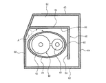
- FIG. 5 is a view of a cross section of the machine room of the outdoor unit according to the first embodiment observed from above.
- the lower side of the paper surface is the front side of the outdoor unit 2.
- FIG. 5 is a plan view of the inside of the machine room 62.
- the first front surface portion 63, the first side surface portion 64, and the first back surface portion 65 are defined as follows.
- the portion of the outer shell portion 50 that constitutes the front surface portion of the machine room 62 is referred to as the first front surface portion 63.
- the portion of the outer shell portion 50 that constitutes the side surface portion of the machine room 62 is referred to as the first side surface portion 64.
- the portion of the outer shell portion 50 that constitutes the back surface portion of the machine room 62 is referred to as the first back surface portion 65.
- the second soundproofing material 80 is a plate-shaped material extending in the vertical direction. Further, the second soundproofing material 80 is provided with a non-woven fabric 84 on the surface on the compressor 40 side. In other words, the second soundproofing material 80 is provided with the non-woven fabric 84 on the surface of the first soundproofing material 70 side. Then, the second soundproof material 80 does not touch the first soundproof material 70, the first front surface portion 63, the first side surface portion 64, and the first back surface portion 65, so that the partition plate 60, the first soundproof material 70, and the first soundproof material 80 are not touched. It is arranged in a space surrounded by a front surface portion 63, a first side surface portion 64, and a first back surface portion 65.
- the second soundproofing material 80 includes a first soundproofing section 81 and a second soundproofing section 82.
- the first soundproofing portion 81 is arranged between the first soundproofing material 70 and the first back surface portion 65.
- the end of the first soundproofing portion 81 on the partition plate 60 side is arranged in the vicinity of the partition plate 60. At this time, the end of the first soundproofing portion 81 on the partition plate 60 side may or may not be in contact with the partition plate 60. However, if the end of the first soundproofing portion 81 on the partition plate 60 side and the partitioning plate 60 are in contact with each other, noise will pass between the first soundproofing portion 81 and the partition plate 60 and the noise will be generated by the first back surface portion 65.
- the second soundproofing portion 82 is arranged between the first soundproofing material 70 and the first side surface portion 64.
- the end portion of the first soundproofing portion 81 on the second soundproofing portion 82 side and the end portion of the second soundproofing portion 82 on the first soundproofing portion 81 side are connected. That is, in the first embodiment, the second soundproofing material 80 has a substantially L-shape in a plan view.
- the main body 41 is arranged closer to the partition plate 60 than the suction muffler 43.
- the noise leaked from the first soundproofing material 70 surrounding the outer peripheral portion of the compressor 40 is reflected at the position A of the partition plate 60 and propagates in the specific direction indicated by the broken line arrow.
- This noise is dispersed between the first soundproofing material 70 and the first soundproofing portion 81 of the second soundproofing material 80 while being reflected by the first soundproofing material 70 and the first soundproofing portion 81. I will do it.
- the noise is absorbed by the non-woven fabric 84 on the surface of the first soundproofing portion 81 while being reflected by the first soundproofing material 70 and the first soundproofing portion 81.
- the noise is attenuated while being reflected by the first soundproofing material 70 and the first soundproofing material 70.
- the outdoor unit 2 according to the first embodiment includes the first soundproofing portion 81 of the second soundproofing material 80, the noise leaked from the first soundproofing material 70 leaks to the outside of the outdoor unit 2. This can be suppressed, and the noise of the outdoor unit 2 can be suppressed more than before.
- the noise leaked from the first soundproofing material 70 surrounding the outer peripheral portion of the compressor 40 is reflected by the partition plate 60 and heads toward the second soundproofing portion 82 of the second soundproofing material 80, the noise is generated.
- the first soundproofing material 70 and the second soundproofing part 82 reflect between the first soundproofing material 70 and the second soundproofing part 82 of the second soundproofing material 80.
- the direction of the noise is dispersed.
- the noise is absorbed by the non-woven fabric 84 on the surface of the second soundproofing portion 82 while being reflected by the first soundproofing material 70 and the second soundproofing portion 82.
- the noise is attenuated while being reflected by the first soundproofing material 70 and the second soundproofing unit 82.
- the outdoor unit 2 according to the first embodiment includes the second soundproofing portion 82 of the second soundproofing material 80, the noise leaked from the first soundproofing material 70 leaks to the outside of the outdoor unit 2. This can be suppressed, and the noise of the outdoor unit 2 can be suppressed more than before.
- the first soundproofing portion 81 arranged between the first soundproofing material 70 and the first back surface portion 65 absorbs and suppresses noise leaking from the first soundproofing material 70 toward the first back surface portion 65. You can also do it.
- the first soundproofing portion 81 is arranged at a position closer to the first soundproofing material 70 than the conventional soundproofing material. With a size smaller than that of the conventional soundproofing material, it is possible to obtain the same soundproofing effect as the conventional soundproofing material. That is, the first soundproofing unit 81 can obtain the same soundproofing effect as the conventional soundproofing material at a lower cost than the conventional soundproofing material.
- the second soundproofing portion 82 arranged between the first soundproofing material 70 and the first side surface portion 64 absorbs and suppresses the noise leaking from the first soundproofing material 70 toward the first side surface portion 64. You can also do it.
- the length of the first soundproofing portion 81 in the longitudinal direction is preferably longer than the length of the first soundproofing portion 81 in the first soundproofing material 70 in the longitudinal direction.
- the space between the first soundproofing material 70 and the first soundproofing portion 81 is longer in the longitudinal direction of the first soundproofing portion 81, the noise reflected by the first soundproofing material 70 and the first soundproofing portion 81 is further suppressed. Because it can be done. Further, it is possible to more reliably absorb the noise leaking from the first soundproofing material 70 toward the first back surface portion 65.
- the length of the second soundproofing portion 82 in the longitudinal direction is preferably longer than the length of the second soundproofing portion 82 in the first soundproofing material 70 in the longitudinal direction.
- the noise reflected by the first soundproof material 70 and the second soundproof portion 82 is further suppressed. Because it can be done. Further, it is possible to more reliably absorb the noise leaking from the first soundproofing material 70 toward the first side surface portion 64.
- the second soundproof material 80 includes the first soundproof part 81 and the second soundproof part 82, but the second soundproof material 80 is the first soundproof part 81 or the second soundproof part 82. It may have only one. As described above, the noise of the outdoor unit 2 can be suppressed more than before by using only one of the first soundproofing unit 81 and the second soundproofing unit 82.
- the outdoor unit 2 of the air conditioner 1 has the outer shell portion 50, the partition plate 60 for partitioning the inside of the outer shell portion 50, the compressor 40, and the outer peripheral portion of the compressor 40.
- the soundproofing material 70 is provided.
- a machine room 62 is formed by a part of the outer shell portion 50 and the partition plate 60, and the compressor 40 is housed in the machine room 62.
- the outdoor unit 2 according to the first embodiment further includes a plate-shaped second soundproofing material 80 extending in the vertical direction in the machine room 62.
- the second soundproofing material 80 is provided with a non-woven fabric 84 on the surface on the compressor 40 side.
- the second soundproof material 80 does not touch the first soundproof material 70, the first front surface portion 63, the first side surface portion 64, and the first back surface portion 65, so that the partition plate 60, the first soundproof material 70, and the first soundproof material 80 are not touched. It is arranged in a space surrounded by a front surface portion 63, a first side surface portion 64, and a first back surface portion 65.
- the second soundproofing material 80 provided outside the first soundproofing material 70 surrounding the outer peripheral portion of the compressor 40 is the outside of the soundproofing material surrounding the outer peripheral portion of the compressor.
- the noise leaking from the first soundproofing material 70 is arranged at a position closer to the position where the noise is reflected by the partition plate 60. Therefore, in the outdoor unit 2 according to the first embodiment, the noise reflected by the partition plate 60 and propagated in a specific direction can be dispersed by the second soundproofing material 80. Therefore, the outdoor unit 2 according to the first embodiment can suppress the noise of the outdoor unit 2 more than before.
- Embodiment 2 The outdoor unit 2 may be provided with a third soundproofing material 90 as described later in the machine room.
- a third soundproofing material 90 as described later in the machine room.
- items not particularly described are the same as those in the first embodiment, and the same functions and configurations as those in the first embodiment are described by using the same reference numerals.
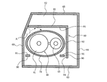
- FIG. 6 is a view of a cross section of the machine room of the outdoor unit according to the second embodiment observed from above.
- the outdoor unit 2 according to the second embodiment includes a third soundproofing material 90 in the machine room 62.
- the third soundproofing material 90 is a plate-shaped material extending in the vertical direction. Further, the third soundproofing material 90 is provided with a non-woven fabric 91 on the surface on the compressor 40 side. In other words, the third soundproofing material 90 is provided with the non-woven fabric 91 on the surface of the first soundproofing material 70 side.
- the third soundproofing material 90 is arranged between the partition plate 60 and the first soundproofing material 70.
- the third soundproofing material 90 is fixed to the partition plate 60 by, for example, adhesion or the like.
- the third soundproofing material 90 is also provided between the first soundproofing material 70, the second soundproofing portion 82 of the second soundproofing material 80, and the first front surface portion 63. It is provided.
- the third soundproofing material 90 is fixed to the second soundproofing portion 82 of the second soundproofing material 80, for example, by adhesion or the like.
- two third soundproofing materials 90 are provided in the machine room 62, but even if only one of the third soundproofing materials 90 is provided in the machine room 62, the outdoor area shown in the first embodiment is shown.
- the noise of the outdoor unit 2 can be further suppressed as compared with the machine 2.
- Embodiment 3 In the third embodiment, an example of a method for fixing the second soundproofing material 80 will be described. Further, in the third embodiment, an example of the shape of the second soundproofing material 80 will be described when there is a refrigerant pipe at the location where the second soundproofing material 80 is arranged.
- items not particularly described are the same as those of the first embodiment or the second embodiment, and the same reference numerals are used for the same functions and configurations as those of the first embodiment or the second embodiment. Will be described.
- FIG. 7 is a side view of the second soundproofing material according to the third embodiment.
- the second soundproofing material 80 according to the third embodiment includes at least one fixing portion 85 fixed to the partition plate 60 at the end portion on the partition plate 60 side.
- the method of fixing the fixing portion 85 and the partition plate 60 is not particularly limited.
- the fixing portion 85 and the partition plate 60 may be fixed by screws.
- a convex portion is provided on one of the fixed portion 85 and the partition plate 60, a concave portion on which the convex portion is hooked is provided on the other side of the fixed portion 85 and the partition plate 60, and the convex portion is hooked on the concave portion to partition the fixed portion 85.
- the plate 60 may be fixed.
- the fixing portion 85 on the second soundproofing material 80 By providing the fixing portion 85 on the second soundproofing material 80 in this way, it becomes easy to arrange the second soundproofing material 80 at a desired position. Further, by providing the fixing portion 85, the end portion of the second soundproofing material 80 on the partition plate 60 side can be arranged in the vicinity of the partition plate 60. Therefore, it is possible to suppress the noise from being transmitted to the first back surface portion 65 side through between the first soundproofing portion 81 and the partition plate 60, and the soundproofing effect of the outdoor unit 2 is improved.
- a refrigerant pipe 20 is provided at a position where the second soundproofing material 80 is arranged. Therefore, the second soundproofing material 80 is formed with a notch 86 and a notch 87 which are opened downward and into which the refrigerant pipe 20 is inserted. Since the notch 86 and the notch 87 are open downward, the second soundproofing material 80 can be lowered even if the refrigerant pipe 20 is present by lowering the second soundproofing material 80 from above the refrigerant pipe 20 to the installation position. It can be installed easily.
- the width of the notch 87 at a position below the refrigerant pipe 20 is smaller than the width at the height of the refrigerant pipe 20.
- Embodiment 4 an example of a specific structure of the second soundproofing material 80 will be described.
- the items not specifically described are the same as those of the first to third embodiments, and the same functions and configurations as those of the first to third embodiments are the same. It will be described using the code of.
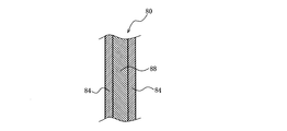
- FIG. 8 is a vertical sectional view of the second soundproofing material according to the fourth embodiment.
- the second soundproofing material 80 according to the fourth embodiment includes a supporting material 88 having a higher rigidity than the non-woven fabric 84.
- the support member 88 is made of, for example, rubber.
- the non-woven fabric 84 is provided on the surface of the support member 88. In FIG. 8, the non-woven fabric 84 is provided on both sides of the support member 88, but the non-woven fabric 84 may be provided at least on the surface on the compressor 40 side.
- the second soundproofing material 80 By configuring the second soundproofing material 80 in this way, it is possible to prevent the second soundproofing material 80 from falling under its own weight.
Abstract
This outdoor unit of an air conditioner according to the present invention is provided with an outer shell part, a partition plate that partitions the inside of the outer shell part, a compressor, and a first soundproof member that surrounds an outer peripheral section of the compressor, wherein a machine compartment is formed by a portion of the outer shell part and the partition plate, and the compressor is contained in the machine compartment, the outdoor unit being further provided with a sheet-like second soundproof member that extends vertically in the machine compartment. The second soundproof member is provided with a non-woven fabric on the surface on the compressor side; and in the outer shell part, when a portion that configures the front surface section of the machine compartment is a first front surface section, a portion that configures the side surface section of the machine compartment is a first side surface section, and a portion that configures the rear surface section of the machine compartment is a first rear surface section, the second sound proof member is disposed in a space surrounded by the partition plate, the first soundproof member, the first front surface section, the first side surface section, and the first rear surface section so as not to be in contact with the first soundproof member, the first front surface section, the first side surface section, and the first rear surface section.
Description
本発明は、騒音の低減を図った空気調和機の室外機に関する。
The present invention relates to an outdoor unit of an air conditioner that reduces noise.
従来、空気調和機の室外機は、外郭部と、外郭部の内部を仕切る仕切板とを備えている。そして、外郭部の一部と仕切板とによって、機械室が形成されている。この機械室には、圧縮機が収納されている。圧縮機が駆動すると、圧縮機から騒音が発生する。このため、従来の室外機は、圧縮機の外周部を囲う防音材を備えている。しかしながら、騒音が、圧縮機の外周部を囲う防音材から漏れてしまう場合がある。圧縮機の外周部を囲う防音材から漏れる騒音とは、例えば、防音材の隙間から防音材の外部へ伝わる騒音である。また例えば、圧縮機の外周部を囲う防音材から漏れる騒音とは、圧縮機又は該圧縮機に接続されている冷媒配管が防音材に接触し、圧縮機の振動が防音材に伝わって発生する騒音である。このため、従来の空気調和機の室外機には、外郭部の背面部における機械室を構成している箇所に防音材を設け、圧縮機の外周部を囲う防音材から漏れた騒音が室外機外へ漏れ出ることの抑制を図ったものも提案されている(特許文献1参照)。
Conventionally, the outdoor unit of an air conditioner is provided with an outer shell portion and a partition plate for partitioning the inside of the outer shell portion. A machine room is formed by a part of the outer shell and a partition plate. A compressor is housed in this machine room. When the compressor is driven, noise is generated from the compressor. Therefore, the conventional outdoor unit is provided with a soundproofing material that surrounds the outer peripheral portion of the compressor. However, noise may leak from the soundproofing material that surrounds the outer periphery of the compressor. The noise leaking from the soundproofing material surrounding the outer peripheral portion of the compressor is, for example, the noise transmitted to the outside of the soundproofing material through the gap of the soundproofing material. Further, for example, the noise leaking from the soundproof material surrounding the outer peripheral portion of the compressor is generated when the compressor or the refrigerant pipe connected to the compressor comes into contact with the soundproof material and the vibration of the compressor is transmitted to the soundproof material. It's noise. For this reason, in the outdoor unit of a conventional air conditioner, a soundproofing material is provided at a portion constituting the machine room on the back surface of the outer shell, and noise leaked from the soundproofing material surrounding the outer peripheral portion of the compressor is emitted from the outdoor unit. A device that suppresses leakage to the outside has also been proposed (see Patent Document 1).
圧縮機の外周部を囲う防音材から漏れた騒音は、機械室の一部を構成する仕切板で反射し、特定の方向に伝播する。この場合、仕切板で反射した騒音が伝播する方向で、室外機の騒音が大きくなる。この騒音を抑制するには、この騒音が伝播する方向を分散させる必要がある。しかしながら、圧縮機の外周部を囲う防音材から漏れた騒音が室外機外へ漏れ出ることの抑制を図った従来の室外機においては、圧縮機の外周部を囲う防音材の外部に設けられた防音材は、外郭部の背面部に設けられている。この外郭部の背面部に設けられた防音材の位置は、圧縮機の外周部を囲う防音材から漏れた騒音が仕切板において反射する位置から遠い。このため、圧縮機の外周部を囲う防音材から漏れた騒音が室外機外へ漏れ出ることの抑制を図った従来の室外機は、仕切板で反射して特定の方向に伝播する騒音を、外郭部の背面部に設けられた防音材によって十分に分散させることができない。したがって、圧縮機の外周部を囲う防音材から漏れた騒音が室外機外へ漏れ出ることの抑制を図った従来の室外機は、圧縮機の外周部を囲う防音材から騒音が漏れた場合、室外機の騒音を十分に抑制できないという課題があった。
The noise leaked from the soundproofing material that surrounds the outer periphery of the compressor is reflected by the partition plate that forms part of the machine room and propagates in a specific direction. In this case, the noise of the outdoor unit increases in the direction in which the noise reflected by the partition plate propagates. In order to suppress this noise, it is necessary to disperse the direction in which this noise propagates. However, in the conventional outdoor unit which aims to suppress the noise leaked from the soundproofing material surrounding the outer peripheral portion of the compressor from leaking to the outside of the outdoor unit, it is provided outside the soundproofing material surrounding the outer peripheral portion of the compressor. The soundproofing material is provided on the back surface of the outer shell. The position of the soundproofing material provided on the back surface of the outer shell portion is far from the position where the noise leaked from the soundproofing material surrounding the outer peripheral portion of the compressor is reflected by the partition plate. For this reason, the conventional outdoor unit, which is designed to prevent the noise leaked from the soundproofing material surrounding the outer peripheral portion of the compressor from leaking to the outside of the outdoor unit, transmits the noise reflected by the partition plate and propagated in a specific direction. It cannot be sufficiently dispersed by the soundproofing material provided on the back surface of the outer shell. Therefore, in the conventional outdoor unit, which is designed to prevent the noise leaked from the soundproofing material surrounding the outer peripheral portion of the compressor from leaking to the outside of the outdoor unit, when the noise leaks from the soundproofing material surrounding the outer peripheral portion of the compressor, There was a problem that the noise of the outdoor unit could not be sufficiently suppressed.
本発明は、上述の課題を解決するためになされたもので、従来よりも室外機の騒音を抑制することができる空気調和機の室外機を得ることを目的とする。
The present invention has been made to solve the above-mentioned problems, and an object of the present invention is to obtain an outdoor unit of an air conditioner capable of suppressing noise of an outdoor unit more than before.
本発明に係る空気調和機の室外機は、外郭部と、前記外郭部の内部を仕切る仕切板と、圧縮機と、前記圧縮機の外周部を囲う第1防音材と、を備え、前記外郭部の一部と前記仕切板とによって機械室が形成され、該機械室に前記圧縮機が収納された空気調和機の室外機であって、前記機械室に上下方向に延びる板状の第2防音材をさらに備え、前記第2防音材は、前記圧縮機側の表面に不織布が設けられており、前記外郭部のうち、前記機械室の前面部を構成する部分を第1前面部とし、前記機械室の側面部を構成する部分を第1側面部とし、前記機械室の背面部を構成する部分を第1背面部とした場合、前記第2防音材は、前記第1防音材、前記第1前面部、前記第1側面部及び前記第1背面部に触れないように、前記仕切板、前記第1防音材、前記第1前面部、前記第1側面部及び前記第1背面部で囲まれた空間に配置されている。
The outdoor unit of the air conditioner according to the present invention includes an outer shell portion, a partition plate for partitioning the inside of the outer shell portion, a compressor, and a first soundproofing material surrounding the outer peripheral portion of the compressor. A machine room is formed by a part of a portion and the partition plate, and the outdoor unit of an air conditioner in which the compressor is housed in the machine room, which is a plate-shaped second extending in the machine room in the vertical direction. A soundproofing material is further provided, and the second soundproofing material is provided with a non-woven fabric on the surface on the compressor side, and a portion of the outer shell portion constituting the front portion of the machine room is designated as the first front surface portion. When the portion constituting the side surface portion of the machine room is the first side surface portion and the portion constituting the back surface portion of the machine room is the first back surface portion, the second soundproofing material is the first soundproofing material, the said. In the partition plate, the first soundproofing material, the first front surface portion, the first side surface portion and the first back surface portion so as not to touch the first front surface portion, the first side surface portion and the first back surface portion. It is located in an enclosed space.
本発明に係る空気調和機の室外機においては、圧縮機の外周部を囲う第1防音材の外部に設けられた第2防音材は、圧縮機の外周部を囲う防音材の外部に設けられた従来の防音材と比べ、第1防音材から漏れた騒音が仕切板において反射する位置に近い場所に配置されている。このため、本発明に係る空気調和機の室外機は、仕切板で反射して特定の方向に伝播する騒音を、第2防音材によって分散させることができる。したがって、本発明に係る室外機は、従来よりも室外機の騒音を抑制することができる。
In the outdoor unit of the air conditioner according to the present invention, the second soundproofing material provided outside the first soundproofing material surrounding the outer peripheral portion of the compressor is provided outside the soundproofing material surrounding the outer peripheral portion of the compressor. Compared with the conventional soundproofing material, the noise leaked from the first soundproofing material is arranged at a position closer to the position where it is reflected on the partition plate. Therefore, in the outdoor unit of the air conditioner according to the present invention, the noise reflected by the partition plate and propagated in a specific direction can be dispersed by the second soundproofing material. Therefore, the outdoor unit according to the present invention can suppress the noise of the outdoor unit more than before.
以下の各実施の形態で、本発明に係る空気調和機の室外機の一例について、図面等を参照しながら説明する。なお、以下の各図面では、各構成部材の大きさの関係が本発明を実施した実物とは異なる場合がある。また、以下の各図面において、同一の符号を付した構成は、同一又はこれに相当する構成である。また、以下の実施の形態で記載されている各構成の形態は、あくまでも例示である。本発明に係る空気調和機の室外機は、以下の実施の形態で記載されている各構成に限定されるものではない。例えば、本発明に係る空気調和機の室外機は、後述の図1に示す冷媒回路を備えた空気調和機に用いられる室外機に限定されるものではない。
An example of the outdoor unit of the air conditioner according to the present invention will be described in each of the following embodiments with reference to drawings and the like. In each of the drawings below, the relationship between the sizes of the constituent members may differ from the actual product in which the present invention is carried out. Further, in each of the following drawings, the configurations with the same reference numerals are the same or equivalent configurations. In addition, the forms of each configuration described in the following embodiments are merely examples. The outdoor unit of the air conditioner according to the present invention is not limited to the configurations described in the following embodiments. For example, the outdoor unit of the air conditioner according to the present invention is not limited to the outdoor unit used in the air conditioner provided with the refrigerant circuit shown in FIG. 1 described later.
実施の形態1.
図1は、実施の形態1に係る室外機が用いられた空気調和機の冷媒回路図である。
実施の形態1に係る室外機2が用いられた空気調和機1は、冷凍サイクル回路10を備えている。冷凍サイクル回路10は、圧縮機40、四方切替弁11、室外熱交換器12、室内熱交換器13、膨張弁14、及び膨張弁15が冷媒配管で接続されて構成されている。なお、冷凍サイクル回路10を循環する冷媒の種類は、限定されない。R410A、R32、水及びCO2等、冷凍サイクル回路10を循環する冷媒として種々の冷媒を用いることができる。 Embodiment 1.
FIG. 1 is a refrigerant circuit diagram of an air conditioner in which the outdoor unit according to the first embodiment is used.
The air conditioner 1 in which theoutdoor unit 2 according to the first embodiment is used includes a refrigeration cycle circuit 10. The refrigeration cycle circuit 10 is configured by connecting a compressor 40, a four-way switching valve 11, an outdoor heat exchanger 12, an indoor heat exchanger 13, an expansion valve 14, and an expansion valve 15 with a refrigerant pipe. The type of refrigerant circulating in the refrigeration cycle circuit 10 is not limited. Various refrigerants such as R410A, R32, water and CO 2 can be used as the refrigerant circulating in the refrigeration cycle circuit 10.
図1は、実施の形態1に係る室外機が用いられた空気調和機の冷媒回路図である。
実施の形態1に係る室外機2が用いられた空気調和機1は、冷凍サイクル回路10を備えている。冷凍サイクル回路10は、圧縮機40、四方切替弁11、室外熱交換器12、室内熱交換器13、膨張弁14、及び膨張弁15が冷媒配管で接続されて構成されている。なお、冷凍サイクル回路10を循環する冷媒の種類は、限定されない。R410A、R32、水及びCO2等、冷凍サイクル回路10を循環する冷媒として種々の冷媒を用いることができる。 Embodiment 1.
FIG. 1 is a refrigerant circuit diagram of an air conditioner in which the outdoor unit according to the first embodiment is used.
The air conditioner 1 in which the
圧縮機40は、冷媒を圧縮するものである。圧縮機40は、冷媒を圧縮する圧縮機構部を有する本体部41を備えている。また、本体部41は、密閉容器である容器42を備えている。圧縮機構部は、容器42に収納されている。また、圧縮機40は、密閉容器であるサクションマフラ43を備えている。サクションマフラ43は、該サクションマフラ43に流入した冷媒を、ガス状冷媒と液状冷媒とに分離するものである。サクションマフラ43の冷媒の流出口は、本体部41の冷媒の流入口に接続されている。そして、サクションマフラ43から本体部41へ、ガス状冷媒が供給される。このガス状冷媒は、本体部41の圧縮機構部で圧縮された後、該本体部41から吐出される。すなわち、サクションマフラ43の冷媒の流入口が、圧縮機40の冷媒の吸入口となっている。また、本体部41の冷媒の流出口が、換言すると容器42の冷媒の流出口が、圧縮機40の冷媒の吐出口となっている。
The compressor 40 compresses the refrigerant. The compressor 40 includes a main body 41 having a compression mechanism for compressing the refrigerant. Further, the main body 41 includes a container 42 which is a closed container. The compression mechanism unit is housed in the container 42. Further, the compressor 40 includes a suction muffler 43 which is a closed container. The suction muffler 43 separates the refrigerant flowing into the suction muffler 43 into a gaseous refrigerant and a liquid refrigerant. The refrigerant outlet of the suction muffler 43 is connected to the refrigerant inlet of the main body 41. Then, the gaseous refrigerant is supplied from the suction muffler 43 to the main body 41. This gaseous refrigerant is compressed by the compression mechanism of the main body 41 and then discharged from the main body 41. That is, the inflow port of the refrigerant of the suction muffler 43 is the suction port of the refrigerant of the compressor 40. Further, the outlet of the refrigerant of the main body 41, in other words, the outlet of the refrigerant of the container 42 is the discharge port of the refrigerant of the compressor 40.
なお、以下では、圧縮機40の冷媒の吸入口に接続されている冷媒配管を、吸入配管18とする。本実施の形態1では、吸入配管18は、サクションマフラ43の上部に接続されている。また、以下では、圧縮機40の冷媒の吐出口に接続されている冷媒配管を、吐出配管19とする。本実施の形態1では、吐出配管19は、容器42の上部に接続されている。
In the following, the refrigerant pipe connected to the refrigerant suction port of the compressor 40 will be referred to as the suction pipe 18. In the first embodiment, the suction pipe 18 is connected to the upper part of the suction muffler 43. Further, in the following, the refrigerant pipe connected to the refrigerant discharge port of the compressor 40 will be referred to as a discharge pipe 19. In the first embodiment, the discharge pipe 19 is connected to the upper part of the container 42.
四方切替弁11は、圧縮機40の冷媒の吸入口、圧縮機40の冷媒の吐出口、室外熱交換器12及び室内熱交換器13に接続されている。四方切替弁11は、圧縮機40の冷媒の吐出口の接続先を、室外熱交換器12又は室内熱交換器13に切り替えるものである。換言すると、四方切替弁11は、圧縮機40の冷媒の吸入口の接続先を、室外熱交換器12又は室内熱交換器13に切り替えるものである。
The four-way switching valve 11 is connected to the refrigerant suction port of the compressor 40, the refrigerant discharge port of the compressor 40, the outdoor heat exchanger 12, and the indoor heat exchanger 13. The four-way switching valve 11 switches the connection destination of the refrigerant discharge port of the compressor 40 to the outdoor heat exchanger 12 or the indoor heat exchanger 13. In other words, the four-way switching valve 11 switches the connection destination of the refrigerant suction port of the compressor 40 to the outdoor heat exchanger 12 or the indoor heat exchanger 13.
室外熱交換器12は、暖房運転時には蒸発器として機能し、冷房運転時には凝縮器として機能する。なお、本実施の形態1では、室外熱交換器12の近傍に、ファン21が設けられている。ファン21は、室外熱交換器12に、室外熱交換器12を流れる冷媒の熱交換対象である室外空気を供給する。このファン21は、モータ22によって駆動される。室内熱交換器13は、暖房運転時には凝縮器として機能し、冷房運転時には蒸発器として機能する。膨張弁14は、室外熱交換器12と室内熱交換器13とを接続する冷媒配管に設けられており、室外熱交換器12を流れる冷媒の流量を調節する。膨張弁15は、室外熱交換器12と室内熱交換器13とを接続する冷媒配管において膨張弁14よりも室内熱交換器13側となる位置に設けられており、室内熱交換器13を流れる冷媒の流量を調節する。
The outdoor heat exchanger 12 functions as an evaporator during the heating operation and as a condenser during the cooling operation. In the first embodiment, the fan 21 is provided in the vicinity of the outdoor heat exchanger 12. The fan 21 supplies the outdoor heat exchanger 12 with outdoor air that is a heat exchange target of the refrigerant flowing through the outdoor heat exchanger 12. The fan 21 is driven by a motor 22. The indoor heat exchanger 13 functions as a condenser during the heating operation and as an evaporator during the cooling operation. The expansion valve 14 is provided in the refrigerant pipe connecting the outdoor heat exchanger 12 and the indoor heat exchanger 13, and regulates the flow rate of the refrigerant flowing through the outdoor heat exchanger 12. The expansion valve 15 is provided at a position closer to the indoor heat exchanger 13 than the expansion valve 14 in the refrigerant pipe connecting the outdoor heat exchanger 12 and the indoor heat exchanger 13, and flows through the indoor heat exchanger 13. Adjust the flow rate of the refrigerant.
また、空気調和機1は、各種センサ及び制御装置38を備えている。具体的には、圧力センサ31は、圧縮機40から吐出された冷媒の圧力を検出する。圧力センサ32は、圧縮機40に吸入される冷媒の圧力を検出する。温度センサ33は、室外熱交換器12に供給される室外空気の温度を検出する。温度センサ34は、室外熱交換器12を流れる冷媒の温度を検出する。温度センサ35は、膨張弁15と室内熱交換器13との間を流れる冷媒の温度を検出する。温度センサ36は、室内熱交換器13を流れる冷媒の温度を検出する。温度センサ37は、室内熱交換器13に供給される室内空気の温度を検出する。制御装置38は、これらのセンサの検出値に基づいて、圧縮機40の圧縮機構部の駆動周波数、ファン21の回転数、膨張弁14の開度、及び膨張弁15の開度等を制御する。
Further, the air conditioner 1 is provided with various sensors and a control device 38. Specifically, the pressure sensor 31 detects the pressure of the refrigerant discharged from the compressor 40. The pressure sensor 32 detects the pressure of the refrigerant sucked into the compressor 40. The temperature sensor 33 detects the temperature of the outdoor air supplied to the outdoor heat exchanger 12. The temperature sensor 34 detects the temperature of the refrigerant flowing through the outdoor heat exchanger 12. The temperature sensor 35 detects the temperature of the refrigerant flowing between the expansion valve 15 and the indoor heat exchanger 13. The temperature sensor 36 detects the temperature of the refrigerant flowing through the indoor heat exchanger 13. The temperature sensor 37 detects the temperature of the indoor air supplied to the indoor heat exchanger 13. The control device 38 controls the drive frequency of the compression mechanism of the compressor 40, the rotation speed of the fan 21, the opening degree of the expansion valve 14, the opening degree of the expansion valve 15, and the like based on the detected values of these sensors. ..
空気調和機1を構成する上述の各構成は、室外機2又は室内機3に収納されている。具体的には、室外機2には、四方切替弁11、室外熱交換器12、膨張弁14、ファン21、モータ22、圧力センサ31、圧力センサ32、温度センサ33、温度センサ34、制御装置38、及び圧縮機40が収納されている。室内機3には、室内熱交換器13、膨張弁15、温度センサ35、温度センサ36、及び温度センサ37が収納されている。また、本実施の形態1に係る空気調和機1では、室外機2に設けられた冷凍サイクル回路10の構成と室内機3に設けられた冷凍サイクル回路10の構成とを接続する冷媒配管に、開閉弁16及び開閉弁17が設けられている。開閉弁16及び開閉弁17は、室外機2に収納されている。なお、本実施の形態1に係る空気調和機1は、2つの室内機3を備えている。これらの室内機3は、並列に、室外機2に接続されている。
Each of the above-mentioned configurations constituting the air conditioner 1 is housed in the outdoor unit 2 or the indoor unit 3. Specifically, the outdoor unit 2 includes a four-way switching valve 11, an outdoor heat exchanger 12, an expansion valve 14, a fan 21, a motor 22, a pressure sensor 31, a pressure sensor 32, a temperature sensor 33, a temperature sensor 34, and a control device. 38 and the compressor 40 are housed in it. The indoor unit 3 houses an indoor heat exchanger 13, an expansion valve 15, a temperature sensor 35, a temperature sensor 36, and a temperature sensor 37. Further, in the air conditioner 1 according to the first embodiment, the refrigerant pipe connecting the configuration of the refrigeration cycle circuit 10 provided in the outdoor unit 2 and the configuration of the refrigeration cycle circuit 10 provided in the indoor unit 3 is connected. An on-off valve 16 and an on-off valve 17 are provided. The on-off valve 16 and the on-off valve 17 are housed in the outdoor unit 2. The air conditioner 1 according to the first embodiment includes two indoor units 3. These indoor units 3 are connected to the outdoor unit 2 in parallel.
図2は、実施の形態1に係る室外機を前方右側から見た斜視図である。図3は、実施の形態1に係る室外機を前方右側から見た斜視図であり、外郭部の天面部、前面部、左側側面部、右側側面部及び背面部を取り外した状態の室外機を示した図である。
室外機2は、例えば略直方体の外郭部50を備えている。また、外郭部50には、室外機2を移動させる際に作業者が把持する複数の取手59が設けられている。外郭部50の構成の仕方は特に限定されないが、本実施の形態1では、天面パネル51、ベース52、正面パネル53、サービスパネル54、右側面パネル55、左側面パネル56、カバーパネル57及びカバーパネル58で、外郭部50を構成している。 FIG. 2 is a perspective view of the outdoor unit according to the first embodiment as viewed from the front right side. FIG. 3 is a perspective view of the outdoor unit according to the first embodiment as viewed from the front right side, and shows the outdoor unit in a state where the top surface portion, the front surface portion, the left side surface portion, the right side surface portion, and the back surface portion of the outer shell portion are removed. It is a figure shown.
Theoutdoor unit 2 includes, for example, an outer shell portion 50 having a substantially rectangular parallelepiped shape. Further, the outer shell portion 50 is provided with a plurality of handles 59 that the operator grips when moving the outdoor unit 2. The method of configuring the outer shell portion 50 is not particularly limited, but in the first embodiment, the top panel 51, the base 52, the front panel 53, the service panel 54, the right side panel 55, the left side panel 56, the cover panel 57, and the like. The cover panel 58 constitutes the outer shell portion 50.
室外機2は、例えば略直方体の外郭部50を備えている。また、外郭部50には、室外機2を移動させる際に作業者が把持する複数の取手59が設けられている。外郭部50の構成の仕方は特に限定されないが、本実施の形態1では、天面パネル51、ベース52、正面パネル53、サービスパネル54、右側面パネル55、左側面パネル56、カバーパネル57及びカバーパネル58で、外郭部50を構成している。 FIG. 2 is a perspective view of the outdoor unit according to the first embodiment as viewed from the front right side. FIG. 3 is a perspective view of the outdoor unit according to the first embodiment as viewed from the front right side, and shows the outdoor unit in a state where the top surface portion, the front surface portion, the left side surface portion, the right side surface portion, and the back surface portion of the outer shell portion are removed. It is a figure shown.
The
天面パネル51は、外郭部50の天面部を構成している。ベース52は、外郭部50の底面部を構成している。正面パネル53は、外郭部50の前面部の左側部分を構成している。サービスパネル54は、外郭部50の前面部の右側の上部部分と、外郭部50の右側側面部の前側の上部部分とを構成している。右側面パネル55は、外郭部50の右側側面部の後ろ側の上部部分と、外郭部50の背面部の右側の上部部分とを構成している。左側面パネル56は、外郭部50の左側側面部を構成している。カバーパネル57は、外郭部50の前面部の右側の下部部分と、外郭部50の右側側面部の前側の下部部分とを構成している。カバーパネル58は、外郭部50の右側側面部の後ろ側の下部部分と、外郭部50の背面部の右側の下部部分とを構成している。
The top panel 51 constitutes the top of the outer shell 50. The base 52 constitutes a bottom surface portion of the outer shell portion 50. The front panel 53 constitutes a left side portion of the front surface portion of the outer shell portion 50. The service panel 54 constitutes an upper portion on the right side of the front surface portion of the outer shell portion 50 and an upper portion on the front side of the right side surface portion of the outer shell portion 50. The right side panel 55 constitutes an upper portion on the rear side of the right side surface portion of the outer shell portion 50 and an upper portion on the right side of the back surface portion of the outer shell portion 50. The left side panel 56 constitutes the left side surface of the outer shell 50. The cover panel 57 constitutes a lower portion on the right side of the front surface portion of the outer shell portion 50 and a lower portion on the front side of the right side surface portion of the outer shell portion 50. The cover panel 58 constitutes a lower portion on the rear side of the right side surface portion of the outer shell portion 50 and a lower portion on the right side of the back surface portion of the outer shell portion 50.
外郭部50の内部は、仕切板60によって、送風機室61と機械室62とに仕切られている。すなわち、機械室62は、外郭部50の一部と仕切板60とによって形成されている。送風機室61には、室外熱交換器12が収納されている。また、図3には図示していないが、送風機室61には、ファン21及びモータ22も収納されている。また、機械室62には、圧縮機40が収納されている。
The inside of the outer shell portion 50 is divided into a blower room 61 and a machine room 62 by a partition plate 60. That is, the machine room 62 is formed by a part of the outer shell portion 50 and the partition plate 60. The outdoor heat exchanger 12 is housed in the blower room 61. Although not shown in FIG. 3, the fan 21 and the motor 22 are also housed in the blower chamber 61. Further, the compressor 40 is housed in the machine room 62.
従来、空気調和機の運転が開始され、圧縮機が駆動されると、圧縮機が振動する。そして、この圧縮機の振動によって騒音が発生する場合がある。このため、従来の空気調和機には、圧縮機の外周部を囲う防音材を備えたものも存在する。本実施の形態1に係る空気調和機1も、圧縮機40の外周部を囲う第1防音材70を備えている。第1防音材70は、従来より存在する防音材と同様の構成である。例えば、第1防音材70は、以下のように構成されている。
Conventionally, when the operation of the air conditioner is started and the compressor is driven, the compressor vibrates. Then, noise may be generated due to the vibration of this compressor. For this reason, some conventional air conditioners are provided with a soundproofing material that surrounds the outer peripheral portion of the compressor. The air conditioner 1 according to the first embodiment also includes a first soundproofing material 70 that surrounds the outer peripheral portion of the compressor 40. The first soundproofing material 70 has the same structure as the conventional soundproofing material. For example, the first soundproofing material 70 is configured as follows.
図4は、実施の形態1に係る室外機の圧縮機周辺を側方から観察した図である。この図4では、第1防音材70を断面で示している。
圧縮機40の側方及び上方は、第1防音材70で囲われている。第1防音材70は、外郭部を構成する、ゴムで形成されたゴム部71を備えている。すなわち、ゴム部71は、外郭部の形状を維持できる剛性を有し、遮音性を有する。また、第1防音材70は、ゴム部71の内周面に、換言するとゴム部71の圧縮機40と対向する側の面に、不織布72が設けられている。不織布72は、吸音効果を有する。 FIG. 4 is a side view of the periphery of the compressor of the outdoor unit according to the first embodiment. In FIG. 4, thefirst soundproofing material 70 is shown in cross section.
The side and the upper side of thecompressor 40 are surrounded by the first soundproofing material 70. The first soundproofing material 70 includes a rubber portion 71 made of rubber, which constitutes an outer shell portion. That is, the rubber portion 71 has rigidity that can maintain the shape of the outer shell portion and has sound insulation. Further, the first soundproofing material 70 is provided with a non-woven fabric 72 on the inner peripheral surface of the rubber portion 71, in other words, on the surface of the rubber portion 71 facing the compressor 40. The non-woven fabric 72 has a sound absorbing effect.
圧縮機40の側方及び上方は、第1防音材70で囲われている。第1防音材70は、外郭部を構成する、ゴムで形成されたゴム部71を備えている。すなわち、ゴム部71は、外郭部の形状を維持できる剛性を有し、遮音性を有する。また、第1防音材70は、ゴム部71の内周面に、換言するとゴム部71の圧縮機40と対向する側の面に、不織布72が設けられている。不織布72は、吸音効果を有する。 FIG. 4 is a side view of the periphery of the compressor of the outdoor unit according to the first embodiment. In FIG. 4, the
The side and the upper side of the
ところで、従来、騒音が圧縮機の外周部を囲う防音材から漏れてしまう場合がある。例えば、圧縮機の外周部を囲う防音材の隙間から、圧縮機の騒音が漏れてしまう。また例えば、圧縮機又は該圧縮機に接続されている冷媒配管が圧縮機の外周部を囲う防音材に接触し、圧縮機の振動が防音材に伝わることがある。この場合、外周部を囲う防音材が振動することによって騒音が発生し、当該騒音が圧縮機の外周部を囲う防音材から漏れてしまう。例えば、圧縮機の外周部を囲う防音材の組立誤差及び圧縮機の組立誤差等によって、圧縮機又は該圧縮機に接続されている冷媒配管が圧縮機の外周部を囲う防音材に接触する場合がある。また例えば、圧縮機の外周部を囲う防音材の経年劣化等による変形によっても、圧縮機又は該圧縮機に接続されている冷媒配管が圧縮機の外周部を囲う防音材に接触する場合がある。また例えば、圧縮機に冷媒配管を接続することによって圧縮機が傾いた場合に、圧縮機又は該圧縮機に接続されている冷媒配管が圧縮機の外周部を囲う防音材に接触する場合がある。
By the way, conventionally, noise may leak from the soundproofing material that surrounds the outer peripheral part of the compressor. For example, the noise of the compressor leaks from the gap of the soundproofing material surrounding the outer peripheral portion of the compressor. Further, for example, the compressor or the refrigerant pipe connected to the compressor may come into contact with the soundproof material surrounding the outer peripheral portion of the compressor, and the vibration of the compressor may be transmitted to the soundproof material. In this case, noise is generated by the vibration of the soundproofing material surrounding the outer peripheral portion, and the noise leaks from the soundproofing material surrounding the outer peripheral portion of the compressor. For example, when the compressor or the refrigerant pipe connected to the compressor comes into contact with the soundproofing material surrounding the outer peripheral portion of the compressor due to an assembly error of the soundproofing material surrounding the outer peripheral portion of the compressor, an assembly error of the compressor, or the like. There is. Further, for example, the compressor or the refrigerant pipe connected to the compressor may come into contact with the soundproof material surrounding the outer peripheral portion of the compressor due to deformation due to aged deterioration of the soundproofing material surrounding the outer peripheral portion of the compressor. .. Further, for example, when the compressor is tilted by connecting the refrigerant pipe to the compressor, the compressor or the refrigerant pipe connected to the compressor may come into contact with the soundproofing material surrounding the outer peripheral portion of the compressor. ..
このため、従来の空気調和機の室外機には、外郭部の背面部における機械室を構成している箇所に防音材を設け、圧縮機の外周部を囲う防音材から漏れた騒音が室外機外へ漏れ出ることの抑制を図ったものも提案されている。
For this reason, in the outdoor unit of a conventional air conditioner, a soundproofing material is provided at a portion constituting the machine room on the back surface of the outer shell, and noise leaked from the soundproofing material surrounding the outer peripheral portion of the compressor is emitted from the outdoor unit. Some have been proposed to prevent leakage to the outside.
ここで、圧縮機の外周部を囲う防音材から漏れた騒音は、機械室の一部を構成する仕切板で反射し、特定の方向に伝播する。この場合、仕切板で反射した騒音が伝播する方向で、室外機の騒音が大きくなる。この騒音を抑制するには、この騒音が伝播する方向を分散させる必要がある。しかしながら、圧縮機の外周部を囲う防音材から漏れた騒音が室外機外へ漏れ出ることの抑制を図った従来の室外機においては、圧縮機の外周部を囲う防音材の外部に設けられた防音材は、外郭部の背面部に設けられている。この外郭部の背面部に設けられた防音材の位置は、圧縮機の外周部を囲う防音材から漏れた騒音が仕切板において反射する位置から遠い。このため、圧縮機の外周部を囲う防音材から漏れた騒音が室外機外へ漏れ出ることの抑制を図った従来の室外機は、仕切板で反射して特定の方向に伝播する騒音を、外郭部の背面部に設けられた防音材によって十分に分散させることができない。したがって、圧縮機の外周部を囲う防音材から漏れた騒音が室外機外へ漏れ出ることの抑制を図った従来の室外機は、圧縮機の外周部を囲う防音材から騒音が漏れた場合、室外機の騒音を十分に抑制できなかった。
Here, the noise leaked from the soundproofing material surrounding the outer peripheral portion of the compressor is reflected by the partition plate that forms a part of the machine room and propagates in a specific direction. In this case, the noise of the outdoor unit increases in the direction in which the noise reflected by the partition plate propagates. In order to suppress this noise, it is necessary to disperse the direction in which this noise propagates. However, in the conventional outdoor unit which aims to suppress the noise leaked from the soundproofing material surrounding the outer peripheral portion of the compressor from leaking to the outside of the outdoor unit, it is provided outside the soundproofing material surrounding the outer peripheral portion of the compressor. The soundproofing material is provided on the back surface of the outer shell. The position of the soundproofing material provided on the back surface of the outer shell is far from the position where the noise leaked from the soundproofing material surrounding the outer peripheral portion of the compressor is reflected by the partition plate. For this reason, the conventional outdoor unit, which is designed to prevent the noise leaked from the soundproofing material surrounding the outer peripheral portion of the compressor from leaking to the outside of the outdoor unit, transmits the noise reflected by the partition plate and propagated in a specific direction. It cannot be sufficiently dispersed by the soundproofing material provided on the back surface of the outer shell. Therefore, in the conventional outdoor unit, which is designed to prevent the noise leaked from the soundproofing material surrounding the outer peripheral portion of the compressor from leaking to the outside of the outdoor unit, when the noise leaks from the soundproofing material surrounding the outer peripheral portion of the compressor, The noise of the outdoor unit could not be sufficiently suppressed.
そこで、本実施の形態1に係る室外機2は、機械室62に、第2防音材80を備えている。
Therefore, the outdoor unit 2 according to the first embodiment includes a second soundproofing material 80 in the machine room 62.
図5は、実施の形態1に係る室外機の機械室の横断面を上方から観察した図である。この図5は、紙面下側が室外機2の前面側となっている。換言すると、図5は、機械室62の内部を平面視した図である。なお、第2防音材80を説明するに際し、第1前面部63、第1側面部64及び第1背面部65を次のように定義する。外郭部50のうち、機械室62の前面部を構成する部分を第1前面部63とする。外郭部50のうち、機械室62の側面部を構成する部分を第1側面部64とする。外郭部50のうち、機械室62の背面部を構成する部分を第1背面部65とする。
FIG. 5 is a view of a cross section of the machine room of the outdoor unit according to the first embodiment observed from above. In FIG. 5, the lower side of the paper surface is the front side of the outdoor unit 2. In other words, FIG. 5 is a plan view of the inside of the machine room 62. In explaining the second soundproofing material 80, the first front surface portion 63, the first side surface portion 64, and the first back surface portion 65 are defined as follows. The portion of the outer shell portion 50 that constitutes the front surface portion of the machine room 62 is referred to as the first front surface portion 63. The portion of the outer shell portion 50 that constitutes the side surface portion of the machine room 62 is referred to as the first side surface portion 64. The portion of the outer shell portion 50 that constitutes the back surface portion of the machine room 62 is referred to as the first back surface portion 65.
第2防音材80は、上下方向に延びる板状のものである。また、第2防音材80は、圧縮機40側の表面に、不織布84が設けられている。換言すると、第2防音材80は、第1防音材70側の表面に、不織布84が設けられている。そして、第2防音材80は、第1防音材70、第1前面部63、第1側面部64及び第1背面部65に触れないように、仕切板60、第1防音材70、第1前面部63、第1側面部64及び第1背面部65で囲まれた空間に配置されている。
The second soundproofing material 80 is a plate-shaped material extending in the vertical direction. Further, the second soundproofing material 80 is provided with a non-woven fabric 84 on the surface on the compressor 40 side. In other words, the second soundproofing material 80 is provided with the non-woven fabric 84 on the surface of the first soundproofing material 70 side. Then, the second soundproof material 80 does not touch the first soundproof material 70, the first front surface portion 63, the first side surface portion 64, and the first back surface portion 65, so that the partition plate 60, the first soundproof material 70, and the first soundproof material 80 are not touched. It is arranged in a space surrounded by a front surface portion 63, a first side surface portion 64, and a first back surface portion 65.
本実施の形態1では、第2防音材80は、第1防音部81及び第2防音部82を備えている。第1防音部81は、第1防音材70と第1背面部65との間に配置されている。第1防音部81の仕切板60側の端部は、仕切板60の近傍に配置されている。この際、第1防音部81の仕切板60側の端部は、仕切板60と接触していてもよいし、仕切板60と接触していなくてもよい。ただし、第1防音部81の仕切板60側の端部と仕切板60とが接触していた方が、第1防音部81と仕切板60との間を通って騒音が第1背面部65側へ伝わることを抑制でき、室外機2の防音効果が向上する。第2防音部82は、第1防音材70と第1側面部64との間に配置されている。本実施の形態1では、第1防音部81の第2防音部82側の端部と、第2防音部82の第1防音部81側の端部とが、接続されている。すなわち、本実施の形態1では、第2防音材80は、平面視略L字形状となっている。また、本実施の形態1に係る圧縮機40は、サクションマフラ43よりも本体部41の方が、仕切板60の近くに配置されている。
In the first embodiment, the second soundproofing material 80 includes a first soundproofing section 81 and a second soundproofing section 82. The first soundproofing portion 81 is arranged between the first soundproofing material 70 and the first back surface portion 65. The end of the first soundproofing portion 81 on the partition plate 60 side is arranged in the vicinity of the partition plate 60. At this time, the end of the first soundproofing portion 81 on the partition plate 60 side may or may not be in contact with the partition plate 60. However, if the end of the first soundproofing portion 81 on the partition plate 60 side and the partitioning plate 60 are in contact with each other, noise will pass between the first soundproofing portion 81 and the partition plate 60 and the noise will be generated by the first back surface portion 65. It is possible to suppress transmission to the side, and the soundproofing effect of the outdoor unit 2 is improved. The second soundproofing portion 82 is arranged between the first soundproofing material 70 and the first side surface portion 64. In the first embodiment, the end portion of the first soundproofing portion 81 on the second soundproofing portion 82 side and the end portion of the second soundproofing portion 82 on the first soundproofing portion 81 side are connected. That is, in the first embodiment, the second soundproofing material 80 has a substantially L-shape in a plan view. Further, in the compressor 40 according to the first embodiment, the main body 41 is arranged closer to the partition plate 60 than the suction muffler 43.
図5に示すように、圧縮機40の外周部を囲う第1防音材70から漏れた騒音が仕切板60の位置Aで反射し、破線矢印で示す特定方向に伝播していったとする。この騒音は、第1防音材70と第2防音材80の第1防音部81との間において、第1防音材70及び第1防音部81で反射していくうちに、騒音の方向が分散していく。また、騒音は、第1防音材70及び第1防音部81で反射していくうちに、第1防音部81の表面の不織布84によって吸収されていく。また、騒音は、第1防音材70及び第1防音材70で反射していくうちに、減衰していく。このように、本実施の形態1に係る室外機2は、第2防音材80の第1防音部81を備えているので、第1防音材70から漏れた騒音が室外機2外へ漏れ出ることを抑制でき、室外機2の騒音を従来よりも抑制することができる。
As shown in FIG. 5, it is assumed that the noise leaked from the first soundproofing material 70 surrounding the outer peripheral portion of the compressor 40 is reflected at the position A of the partition plate 60 and propagates in the specific direction indicated by the broken line arrow. This noise is dispersed between the first soundproofing material 70 and the first soundproofing portion 81 of the second soundproofing material 80 while being reflected by the first soundproofing material 70 and the first soundproofing portion 81. I will do it. Further, the noise is absorbed by the non-woven fabric 84 on the surface of the first soundproofing portion 81 while being reflected by the first soundproofing material 70 and the first soundproofing portion 81. Further, the noise is attenuated while being reflected by the first soundproofing material 70 and the first soundproofing material 70. As described above, since the outdoor unit 2 according to the first embodiment includes the first soundproofing portion 81 of the second soundproofing material 80, the noise leaked from the first soundproofing material 70 leaks to the outside of the outdoor unit 2. This can be suppressed, and the noise of the outdoor unit 2 can be suppressed more than before.
また、圧縮機40の外周部を囲う第1防音材70から漏れた騒音が仕切板60で反射し、第2防音材80の第2防音部82の方へ向かっていった場合、該騒音は、第1防音材70と第2防音材80の第2防音部82との間において、第1防音材70及び第2防音部82で反射していく。そして、この騒音は、第1防音材70及び第2防音部82で反射していくうちに、騒音の方向が分散していく。また、騒音は、第1防音材70及び第2防音部82で反射していくうちに、第2防音部82の表面の不織布84によって吸収されていく。また、騒音は、第1防音材70及び第2防音部82で反射していくうちに、減衰していく。このように、本実施の形態1に係る室外機2は、第2防音材80の第2防音部82を備えているので、第1防音材70から漏れた騒音が室外機2外へ漏れ出ることを抑制でき、室外機2の騒音を従来よりも抑制することができる。
Further, when the noise leaked from the first soundproofing material 70 surrounding the outer peripheral portion of the compressor 40 is reflected by the partition plate 60 and heads toward the second soundproofing portion 82 of the second soundproofing material 80, the noise is generated. , The first soundproofing material 70 and the second soundproofing part 82 reflect between the first soundproofing material 70 and the second soundproofing part 82 of the second soundproofing material 80. Then, as the noise is reflected by the first soundproofing material 70 and the second soundproofing unit 82, the direction of the noise is dispersed. Further, the noise is absorbed by the non-woven fabric 84 on the surface of the second soundproofing portion 82 while being reflected by the first soundproofing material 70 and the second soundproofing portion 82. Further, the noise is attenuated while being reflected by the first soundproofing material 70 and the second soundproofing unit 82. As described above, since the outdoor unit 2 according to the first embodiment includes the second soundproofing portion 82 of the second soundproofing material 80, the noise leaked from the first soundproofing material 70 leaks to the outside of the outdoor unit 2. This can be suppressed, and the noise of the outdoor unit 2 can be suppressed more than before.
また、第1防音材70と第1背面部65との間に配置されている第1防音部81は、第1防音材70から第1背面部65に向かって漏れる騒音を吸収し、抑制することもできる。この際、外郭部の背面部に設けられた従来の防音材と比べた場合、第1防音部81は、従来の防音材よりも第1防音材70に近い位置に配置されているので、従来の防音材よりも小さな大きさで、従来の防音材と同等の防音効果を得ることができる。すなわち、第1防音部81は、従来の防音材よりも安価に、従来の防音材と同等の防音効果を得ることができる。
Further, the first soundproofing portion 81 arranged between the first soundproofing material 70 and the first back surface portion 65 absorbs and suppresses noise leaking from the first soundproofing material 70 toward the first back surface portion 65. You can also do it. At this time, when compared with the conventional soundproofing material provided on the back surface of the outer shell portion, the first soundproofing portion 81 is arranged at a position closer to the first soundproofing material 70 than the conventional soundproofing material. With a size smaller than that of the conventional soundproofing material, it is possible to obtain the same soundproofing effect as the conventional soundproofing material. That is, the first soundproofing unit 81 can obtain the same soundproofing effect as the conventional soundproofing material at a lower cost than the conventional soundproofing material.
また、第1防音材70と第1側面部64との間に配置されている第2防音部82は、第1防音材70から第1側面部64に向かって漏れる騒音を吸収し、抑制することもできる。
Further, the second soundproofing portion 82 arranged between the first soundproofing material 70 and the first side surface portion 64 absorbs and suppresses the noise leaking from the first soundproofing material 70 toward the first side surface portion 64. You can also do it.
なお、平面視において、第1防音部81の長手方向の長さは、第1防音材70における第1防音部81の長手方向の長さよりも長いことが好ましい。第1防音材70と第1防音部81との間の空間が第1防音部81の長手方向に長い方が、第1防音材70及び第1防音部81で反射していく騒音をより抑制できるからである。また、第1防音材70から第1背面部65に向かって漏れる騒音をより確実に吸収できるからである。また、平面視において、第2防音部82の長手方向の長さは、第1防音材70における第2防音部82の長手方向の長さよりも長いことが好ましい。第1防音材70と第2防音部82との間の空間が第2防音部82の長手方向に長い方が、第1防音材70及び第2防音部82で反射していく騒音をより抑制できるからである。また、第1防音材70から第1側面部64に向かって漏れる騒音をより確実に吸収できるからである。
In a plan view, the length of the first soundproofing portion 81 in the longitudinal direction is preferably longer than the length of the first soundproofing portion 81 in the first soundproofing material 70 in the longitudinal direction. When the space between the first soundproofing material 70 and the first soundproofing portion 81 is longer in the longitudinal direction of the first soundproofing portion 81, the noise reflected by the first soundproofing material 70 and the first soundproofing portion 81 is further suppressed. Because it can be done. Further, it is possible to more reliably absorb the noise leaking from the first soundproofing material 70 toward the first back surface portion 65. Further, in a plan view, the length of the second soundproofing portion 82 in the longitudinal direction is preferably longer than the length of the second soundproofing portion 82 in the first soundproofing material 70 in the longitudinal direction. When the space between the first soundproof material 70 and the second soundproof portion 82 is longer in the longitudinal direction of the second soundproof portion 82, the noise reflected by the first soundproof material 70 and the second soundproof portion 82 is further suppressed. Because it can be done. Further, it is possible to more reliably absorb the noise leaking from the first soundproofing material 70 toward the first side surface portion 64.
また、本実施の形態1に係る第2防音材80は第1防音部81及び第2防音部82を備えていたが、第2防音材80は第1防音部81又は第2防音部82の一方のみを備えていてもよい。上述のように、第1防音部81又は第2防音部82の一方のみでも、室外機2の騒音を従来よりも抑制することができる。
Further, the second soundproof material 80 according to the first embodiment includes the first soundproof part 81 and the second soundproof part 82, but the second soundproof material 80 is the first soundproof part 81 or the second soundproof part 82. It may have only one. As described above, the noise of the outdoor unit 2 can be suppressed more than before by using only one of the first soundproofing unit 81 and the second soundproofing unit 82.
以上、本実施の形態1に係る空気調和機1の室外機2は、外郭部50と、外郭部50の内部を仕切る仕切板60と、圧縮機40と、圧縮機40の外周部を囲う第1防音材70と、を備えている。そして、外郭部50の一部と仕切板60とによって機械室62が形成され、該機械室62に圧縮機40が収納されている。また、本実施の形態1に係る室外機2は、機械室62に、上下方向に延びる板状の第2防音材80をさらに備えている。第2防音材80は、圧縮機40側の表面に不織布84が設けられている。そして、第2防音材80は、第1防音材70、第1前面部63、第1側面部64及び第1背面部65に触れないように、仕切板60、第1防音材70、第1前面部63、第1側面部64及び第1背面部65で囲まれた空間に配置されている。
As described above, the outdoor unit 2 of the air conditioner 1 according to the first embodiment has the outer shell portion 50, the partition plate 60 for partitioning the inside of the outer shell portion 50, the compressor 40, and the outer peripheral portion of the compressor 40. 1 The soundproofing material 70 is provided. A machine room 62 is formed by a part of the outer shell portion 50 and the partition plate 60, and the compressor 40 is housed in the machine room 62. Further, the outdoor unit 2 according to the first embodiment further includes a plate-shaped second soundproofing material 80 extending in the vertical direction in the machine room 62. The second soundproofing material 80 is provided with a non-woven fabric 84 on the surface on the compressor 40 side. Then, the second soundproof material 80 does not touch the first soundproof material 70, the first front surface portion 63, the first side surface portion 64, and the first back surface portion 65, so that the partition plate 60, the first soundproof material 70, and the first soundproof material 80 are not touched. It is arranged in a space surrounded by a front surface portion 63, a first side surface portion 64, and a first back surface portion 65.
本実施の形態1に係る室外機2においては、圧縮機40の外周部を囲う第1防音材70の外部に設けられた第2防音材80は、圧縮機の外周部を囲う防音材の外部に設けられた従来の防音材と比べ、第1防音材70から漏れた騒音が仕切板60において反射する位置に近い場所に配置されている。このため、本実施の形態1に係る室外機2は、仕切板60で反射して特定の方向に伝播する騒音を、第2防音材80によって分散させることができる。したがって、本実施の形態1に係る室外機2は、従来よりも室外機2の騒音を抑制することができる。
In the outdoor unit 2 according to the first embodiment, the second soundproofing material 80 provided outside the first soundproofing material 70 surrounding the outer peripheral portion of the compressor 40 is the outside of the soundproofing material surrounding the outer peripheral portion of the compressor. Compared with the conventional soundproofing material provided in the above, the noise leaking from the first soundproofing material 70 is arranged at a position closer to the position where the noise is reflected by the partition plate 60. Therefore, in the outdoor unit 2 according to the first embodiment, the noise reflected by the partition plate 60 and propagated in a specific direction can be dispersed by the second soundproofing material 80. Therefore, the outdoor unit 2 according to the first embodiment can suppress the noise of the outdoor unit 2 more than before.
実施の形態2.
室外機2は、機械室に、後述のような第3防音材90を備えていてもよい。なお、本実施の形態2において、特に記述しない項目については実施の形態1と同様とし、実施の形態1と同一の機能及び構成については同一の符号を用いて述べることとする。Embodiment 2.
Theoutdoor unit 2 may be provided with a third soundproofing material 90 as described later in the machine room. In the second embodiment, items not particularly described are the same as those in the first embodiment, and the same functions and configurations as those in the first embodiment are described by using the same reference numerals.
室外機2は、機械室に、後述のような第3防音材90を備えていてもよい。なお、本実施の形態2において、特に記述しない項目については実施の形態1と同様とし、実施の形態1と同一の機能及び構成については同一の符号を用いて述べることとする。
The
図6は、実施の形態2に係る室外機の機械室の横断面を上方から観察した図である。
本実施の形態2に係る室外機2は、機械室62に、第3防音材90を備えている。第3防音材90は、上下方向に延びる板状のものである。また、第3防音材90は、圧縮機40側の表面に、不織布91が設けられている。換言すると、第3防音材90は、第1防音材70側の表面に、不織布91が設けられている。 FIG. 6 is a view of a cross section of the machine room of the outdoor unit according to the second embodiment observed from above.
Theoutdoor unit 2 according to the second embodiment includes a third soundproofing material 90 in the machine room 62. The third soundproofing material 90 is a plate-shaped material extending in the vertical direction. Further, the third soundproofing material 90 is provided with a non-woven fabric 91 on the surface on the compressor 40 side. In other words, the third soundproofing material 90 is provided with the non-woven fabric 91 on the surface of the first soundproofing material 70 side.
本実施の形態2に係る室外機2は、機械室62に、第3防音材90を備えている。第3防音材90は、上下方向に延びる板状のものである。また、第3防音材90は、圧縮機40側の表面に、不織布91が設けられている。換言すると、第3防音材90は、第1防音材70側の表面に、不織布91が設けられている。 FIG. 6 is a view of a cross section of the machine room of the outdoor unit according to the second embodiment observed from above.
The
図6に示すように、第3防音材90は、仕切板60と第1防音材70との間に配置されている。この第3防音材90は、例えば、接着等により、仕切板60に固定されている。この第3防音材90を備えることにより、仕切板60と第1防音材70との間を通って第1前面部63に向かう騒音を吸収することができ、実施の形態1で示した室外機2よりもさらに、室外機2の騒音を抑制することができる。
As shown in FIG. 6, the third soundproofing material 90 is arranged between the partition plate 60 and the first soundproofing material 70. The third soundproofing material 90 is fixed to the partition plate 60 by, for example, adhesion or the like. By providing the third soundproofing material 90, it is possible to absorb noise toward the first front surface portion 63 through between the partition plate 60 and the first soundproofing material 70, and the outdoor unit shown in the first embodiment can be absorbed. More than 2, the noise of the outdoor unit 2 can be suppressed.
また、本実施の形態2に係る室外機2は、第1防音材70と、第2防音材80の第2防音部82と、第1前面部63との間にも第3防音材90が設けられている。この第3防音材90は、例えば、接着等により、第2防音材80の第2防音部82に固定されている。この第3防音材90を備えることにより、第1防音材70と第2防音部82との間を通って第1前面部63に向かう騒音を吸収することができ、実施の形態1で示した室外機2よりもさらに、室外機2の騒音を抑制することができる。
Further, in the outdoor unit 2 according to the second embodiment, the third soundproofing material 90 is also provided between the first soundproofing material 70, the second soundproofing portion 82 of the second soundproofing material 80, and the first front surface portion 63. It is provided. The third soundproofing material 90 is fixed to the second soundproofing portion 82 of the second soundproofing material 80, for example, by adhesion or the like. By providing the third soundproofing material 90, it is possible to absorb the noise that passes between the first soundproofing material 70 and the second soundproofing portion 82 and heads toward the first front surface portion 63, which is shown in the first embodiment. The noise of the outdoor unit 2 can be further suppressed as compared with the outdoor unit 2.
なお、本実施の形態2では2つの第3防音材90を機械室62に設けたが、どちらか一方の第3防音材90を機械室62に設けるだけでも、実施の形態1で示した室外機2よりもさらに、室外機2の騒音を抑制することができる。
In the second embodiment, two third soundproofing materials 90 are provided in the machine room 62, but even if only one of the third soundproofing materials 90 is provided in the machine room 62, the outdoor area shown in the first embodiment is shown. The noise of the outdoor unit 2 can be further suppressed as compared with the machine 2.
実施の形態3.
本実施の形態3では、第2防音材80の固定方法の一例について説明する。また、本実施の形態3では、第2防音材80の配置箇所に冷媒配管がある場合における、第2防音材80の形状の一例について説明する。なお、本実施の形態3において、特に記述しない項目については実施の形態1又は実施の形態2と同様とし、実施の形態1又は実施の形態2と同一の機能及び構成については同一の符号を用いて述べることとする。Embodiment 3.
In the third embodiment, an example of a method for fixing thesecond soundproofing material 80 will be described. Further, in the third embodiment, an example of the shape of the second soundproofing material 80 will be described when there is a refrigerant pipe at the location where the second soundproofing material 80 is arranged. In the third embodiment, items not particularly described are the same as those of the first embodiment or the second embodiment, and the same reference numerals are used for the same functions and configurations as those of the first embodiment or the second embodiment. Will be described.
本実施の形態3では、第2防音材80の固定方法の一例について説明する。また、本実施の形態3では、第2防音材80の配置箇所に冷媒配管がある場合における、第2防音材80の形状の一例について説明する。なお、本実施の形態3において、特に記述しない項目については実施の形態1又は実施の形態2と同様とし、実施の形態1又は実施の形態2と同一の機能及び構成については同一の符号を用いて述べることとする。
In the third embodiment, an example of a method for fixing the
図7は、実施の形態3に係る第2防音材を側方から見た図である。
本実施の形態3に係る第2防音材80は、仕切板60側の端部に、仕切板60に固定される固定部85を少なくとも1つ備えている。固定部85と仕切板60との固定方法は、特に限定されない。例えば、固定部85と仕切板60とをネジ止めで固定してもよい。また例えば、固定部85及び仕切板60の一方に凸部を設け、固定部85及び仕切板60の他方に凸部が引っ掛けられる凹部を設け、凸部を凹部に引っ掛けることによって固定部85と仕切板60とを固定してもよい。 FIG. 7 is a side view of the second soundproofing material according to the third embodiment.
Thesecond soundproofing material 80 according to the third embodiment includes at least one fixing portion 85 fixed to the partition plate 60 at the end portion on the partition plate 60 side. The method of fixing the fixing portion 85 and the partition plate 60 is not particularly limited. For example, the fixing portion 85 and the partition plate 60 may be fixed by screws. Further, for example, a convex portion is provided on one of the fixed portion 85 and the partition plate 60, a concave portion on which the convex portion is hooked is provided on the other side of the fixed portion 85 and the partition plate 60, and the convex portion is hooked on the concave portion to partition the fixed portion 85. The plate 60 may be fixed.
本実施の形態3に係る第2防音材80は、仕切板60側の端部に、仕切板60に固定される固定部85を少なくとも1つ備えている。固定部85と仕切板60との固定方法は、特に限定されない。例えば、固定部85と仕切板60とをネジ止めで固定してもよい。また例えば、固定部85及び仕切板60の一方に凸部を設け、固定部85及び仕切板60の他方に凸部が引っ掛けられる凹部を設け、凸部を凹部に引っ掛けることによって固定部85と仕切板60とを固定してもよい。 FIG. 7 is a side view of the second soundproofing material according to the third embodiment.
The
このように、第2防音材80に固定部85を設けることにより、第2防音材80を所望の位置に配置することが容易となる。また、固定部85を設けることにより、第2防音材80の仕切板60側の端部を仕切板60の近傍に配置できる。このため、第1防音部81と仕切板60との間を通って騒音が第1背面部65側へ伝わることを抑制でき、室外機2の防音効果が向上する。
By providing the fixing portion 85 on the second soundproofing material 80 in this way, it becomes easy to arrange the second soundproofing material 80 at a desired position. Further, by providing the fixing portion 85, the end portion of the second soundproofing material 80 on the partition plate 60 side can be arranged in the vicinity of the partition plate 60. Therefore, it is possible to suppress the noise from being transmitted to the first back surface portion 65 side through between the first soundproofing portion 81 and the partition plate 60, and the soundproofing effect of the outdoor unit 2 is improved.
また、本実施の形態3に係る室外機2の機械室62には、第2防音材80が配置される位置に、冷媒配管20が設けられている。そこで、第2防音材80には、下方に開口し、冷媒配管20が挿入される切り欠き86及び切り欠き87が形成されている。切り欠き86及び切り欠き87は下方に開口しているため、冷媒配管20の上方から第2防音材80を設置位置に下ろしていくことにより、冷媒配管20がある場合でも第2防音材80を容易に設置することができる。
Further, in the machine room 62 of the outdoor unit 2 according to the third embodiment, a refrigerant pipe 20 is provided at a position where the second soundproofing material 80 is arranged. Therefore, the second soundproofing material 80 is formed with a notch 86 and a notch 87 which are opened downward and into which the refrigerant pipe 20 is inserted. Since the notch 86 and the notch 87 are open downward, the second soundproofing material 80 can be lowered even if the refrigerant pipe 20 is present by lowering the second soundproofing material 80 from above the refrigerant pipe 20 to the installation position. It can be installed easily.
また、切り欠き87は、冷媒配管20よりも下方となる位置の横幅が、冷媒配管20の高さでの横幅よりも小さくなっている。第2防音材80に形成される切り欠きを切り欠き87のような形状にすることにより、第2防音材80が設置されない箇所を少なくでき、切り欠きを形成することによる防音効果の低下を抑制することができる。
Further, the width of the notch 87 at a position below the refrigerant pipe 20 is smaller than the width at the height of the refrigerant pipe 20. By forming the notch formed in the second soundproofing material 80 into a shape like the notch 87, the number of places where the second soundproofing material 80 is not installed can be reduced, and the deterioration of the soundproofing effect due to the formation of the notch can be suppressed. can do.
実施の形態4.
本実施の形態4では、第2防音材80の具体的な構造の一例について説明する。なお、本実施の形態4において、特に記述しない項目については実施の形態1~実施の形態3のいずれかと同様とし、実施の形態1~実施の形態3のいずれかと同一の機能及び構成については同一の符号を用いて述べることとする。 Embodiment 4.
In the fourth embodiment, an example of a specific structure of thesecond soundproofing material 80 will be described. In the fourth embodiment, the items not specifically described are the same as those of the first to third embodiments, and the same functions and configurations as those of the first to third embodiments are the same. It will be described using the code of.
本実施の形態4では、第2防音材80の具体的な構造の一例について説明する。なお、本実施の形態4において、特に記述しない項目については実施の形態1~実施の形態3のいずれかと同様とし、実施の形態1~実施の形態3のいずれかと同一の機能及び構成については同一の符号を用いて述べることとする。 Embodiment 4.
In the fourth embodiment, an example of a specific structure of the
図8は、実施の形態4に係る第2防音材の縦断面図である。
本実施の形態4に係る第2防音材80は、不織布84よりも剛性の高い支持材88を備えている。支持材88は、例えば、ゴムで形成されている。そして、不織布84は、支持材88の表面に設けられている。なお、図8では支持材88の両面に不織布84が設けられているが、不織布84は、少なくとも圧縮機40側の表面に設けられていればよい。 FIG. 8 is a vertical sectional view of the second soundproofing material according to the fourth embodiment.
Thesecond soundproofing material 80 according to the fourth embodiment includes a supporting material 88 having a higher rigidity than the non-woven fabric 84. The support member 88 is made of, for example, rubber. The non-woven fabric 84 is provided on the surface of the support member 88. In FIG. 8, the non-woven fabric 84 is provided on both sides of the support member 88, but the non-woven fabric 84 may be provided at least on the surface on the compressor 40 side.
本実施の形態4に係る第2防音材80は、不織布84よりも剛性の高い支持材88を備えている。支持材88は、例えば、ゴムで形成されている。そして、不織布84は、支持材88の表面に設けられている。なお、図8では支持材88の両面に不織布84が設けられているが、不織布84は、少なくとも圧縮機40側の表面に設けられていればよい。 FIG. 8 is a vertical sectional view of the second soundproofing material according to the fourth embodiment.
The
第2防音材80をこのように構成することにより、第2防音材80が自重で倒れることを抑制できる。
By configuring the second soundproofing material 80 in this way, it is possible to prevent the second soundproofing material 80 from falling under its own weight.
1 空気調和機、2 室外機、3 室内機、10 冷凍サイクル回路、11 四方切替弁、12 室外熱交換器、13 室内熱交換器、14 膨張弁、15 膨張弁、16 開閉弁、17 開閉弁、18 吸入配管、19 吐出配管、20 冷媒配管、21 ファン、22 モータ、31 圧力センサ、32 圧力センサ、33 温度センサ、34 温度センサ、35 温度センサ、36 温度センサ、37 温度センサ、38 制御装置、40 圧縮機、41 本体部、42 容器、43 サクションマフラ、50 外郭部、51 天面パネル、52 ベース、53 正面パネル、54 サービスパネル、55 右側面パネル、56 左側面パネル、57 カバーパネル、58 カバーパネル、59 取手、60 仕切板、61 送風機室、62 機械室、63 第1前面部、64 第1側面部、65 第1背面部、70 第1防音材、71 ゴム部、72 不織布、80 第2防音材、81 第1防音部、82 第2防音部、84 不織布、85 固定部、86 切り欠き、87 切り欠き、88 支持材、90 第3防音材、91 不織布。
1 air conditioner, 2 outdoor unit, 3 indoor unit, 10 refrigeration cycle circuit, 11 four-way switching valve, 12 outdoor heat exchanger, 13 indoor heat exchanger, 14 expansion valve, 15 expansion valve, 16 on-off valve, 17 on-off valve , 18 suction pipe, 19 discharge pipe, 20 refrigerant pipe, 21 fan, 22 motor, 31 pressure sensor, 32 pressure sensor, 33 temperature sensor, 34 temperature sensor, 35 temperature sensor, 36 temperature sensor, 37 temperature sensor, 38 control device , 40 compressor, 41 main body, 42 container, 43 suction muffler, 50 outer shell, 51 top panel, 52 base, 53 front panel, 54 service panel, 55 right side panel, 56 left side panel, 57 cover panel, 58 cover panel, 59 handle, 60 partition plate, 61 blower room, 62 machine room, 63 first front part, 64 first side surface part, 65 first back part, 70 first soundproof material, 71 rubber part, 72 non-woven fabric, 80 2nd soundproofing material, 81 1st soundproofing part, 82 2nd soundproofing part, 84 non-woven fabric, 85 fixed part, 86 notch, 87 notch, 88 support material, 90 3rd soundproofing material, 91 non-woven fabric.
Claims (9)
- 外郭部と、
前記外郭部の内部を仕切る仕切板と、
圧縮機と、
前記圧縮機の外周部を囲う第1防音材と、
を備え、
前記外郭部の一部と前記仕切板とによって機械室が形成され、該機械室に前記圧縮機が収納された空気調和機の室外機であって、
前記機械室に上下方向に延びる板状の第2防音材をさらに備え、
前記第2防音材は、前記圧縮機側の表面に不織布が設けられており、
前記外郭部のうち、前記機械室の前面部を構成する部分を第1前面部とし、前記機械室の側面部を構成する部分を第1側面部とし、前記機械室の背面部を構成する部分を第1背面部とした場合、
前記第2防音材は、前記第1防音材、前記第1前面部、前記第1側面部及び前記第1背面部に触れないように、前記仕切板、前記第1防音材、前記第1前面部、前記第1側面部及び前記第1背面部で囲まれた空間に配置されている空気調和機の室外機。 Outer part and
A partition plate that partitions the inside of the outer shell,
With a compressor,
A first soundproofing material that surrounds the outer periphery of the compressor,
With
An outdoor unit of an air conditioner in which a machine room is formed by a part of the outer shell portion and the partition plate, and the compressor is housed in the machine room.
The machine room is further provided with a plate-shaped second soundproofing material extending in the vertical direction.
The second soundproofing material is provided with a non-woven fabric on the surface on the compressor side.
Of the outer shell, the portion constituting the front surface of the machine room is designated as the first front surface portion, the portion constituting the side surface portion of the machine room is designated as the first side surface portion, and the portion constituting the back surface portion of the machine room. When is the first back part,
The second soundproof material includes the partition plate, the first soundproof material, and the first front surface so as not to touch the first soundproof material, the first front surface portion, the first side surface portion, and the first back surface portion. An outdoor unit of an air conditioner arranged in a space surrounded by a unit, the first side surface portion, and the first back surface portion. - 前記第2防音材は、前記第1防音材と前記第1背面部との間に配置されている請求項1に記載の空気調和機の室外機。 The outdoor unit of the air conditioner according to claim 1, wherein the second soundproofing material is arranged between the first soundproofing material and the first back surface portion.
- 前記第2防音材は、前記第1防音材と前記第1側面部との間に配置されている請求項1又は請求項2に記載の空気調和機の室外機。 The outdoor unit of the air conditioner according to claim 1 or 2, wherein the second soundproofing material is arranged between the first soundproofing material and the first side surface portion.
- 前記機械室に、上下方向に延びる板状の第3防音材をさらに備え、
前記第3防音材は、前記圧縮機側の表面に不織布が設けられており、
前記第3防音材は、前記第1防音材と、前記第2防音材と、前記第1前面部との間に配置されている請求項3に記載の空気調和機の室外機。 The machine room is further provided with a plate-shaped third soundproofing material extending in the vertical direction.
The third soundproofing material is provided with a non-woven fabric on the surface on the compressor side.
The outdoor unit of the air conditioner according to claim 3, wherein the third soundproofing material is arranged between the first soundproofing material, the second soundproofing material, and the first front surface portion. - 前記機械室に、上下方向に延びる板状の第3防音材をさらに備え、
前記第3防音材は、前記圧縮機側の表面に不織布が設けられており、
前記第3防音材は、前記仕切板と前記第1防音材との間に配置されている請求項1~請求項4のいずれか一項に記載の空気調和機の室外機。 The machine room is further provided with a plate-shaped third soundproofing material extending in the vertical direction.
The third soundproofing material is provided with a non-woven fabric on the surface on the compressor side.
The outdoor unit of the air conditioner according to any one of claims 1 to 4, wherein the third soundproofing material is arranged between the partition plate and the first soundproofing material. - 前記第2防音材は、前記仕切板に固定される固定部を備えている請求項1~請求項5のいずれか一項に記載の空気調和機の室外機。 The outdoor unit of the air conditioner according to any one of claims 1 to 5, wherein the second soundproofing material includes a fixing portion fixed to the partition plate.
- 前記機械室には、冷媒が流れる冷媒配管が設けられており、
前記第2防音材には、下方に開口し、前記冷媒配管が挿入される切り欠きが形成されている請求項1~請求項6のいずれか一項に記載の空気調和機の室外機。 The machine room is provided with a refrigerant pipe through which the refrigerant flows.
The outdoor unit of the air conditioner according to any one of claims 1 to 6, wherein the second soundproofing material is formed with a notch that opens downward and into which the refrigerant pipe is inserted. - 前記切り欠きは、前記冷媒配管よりも下方となる位置の横幅が、前記冷媒配管の高さでの横幅よりも小さくなっている請求項7に記載の空気調和機の室外機。 The outdoor unit of the air conditioner according to claim 7, wherein the notch has a width at a position below the refrigerant pipe smaller than the width at the height of the refrigerant pipe.
- 前記第2防音材は、前記不織布よりも剛性の高い支持材を備え、
前記不織布は、前記支持材の表面に設けられている請求項1~請求項8のいずれか一項に記載の空気調和機の室外機。 The second soundproofing material includes a supporting material having a higher rigidity than the non-woven fabric.
The outdoor unit of the air conditioner according to any one of claims 1 to 8, wherein the non-woven fabric is provided on the surface of the support material.
Priority Applications (3)
| Application Number | Priority Date | Filing Date | Title |
|---|---|---|---|
| JP2021529597A JP7118273B2 (en) | 2019-07-02 | 2019-07-02 | outdoor unit of air conditioner |
| PCT/JP2019/026302 WO2021001925A1 (en) | 2019-07-02 | 2019-07-02 | Outdoor unit of air conditioner |
| CN201990000397.0U CN213841140U (en) | 2019-07-02 | 2019-07-02 | Outdoor unit of air conditioner |
Applications Claiming Priority (1)
| Application Number | Priority Date | Filing Date | Title |
|---|---|---|---|
| PCT/JP2019/026302 WO2021001925A1 (en) | 2019-07-02 | 2019-07-02 | Outdoor unit of air conditioner |
Publications (1)
| Publication Number | Publication Date |
|---|---|
| WO2021001925A1 true WO2021001925A1 (en) | 2021-01-07 |
Family
ID=74100120
Family Applications (1)
| Application Number | Title | Priority Date | Filing Date |
|---|---|---|---|
| PCT/JP2019/026302 WO2021001925A1 (en) | 2019-07-02 | 2019-07-02 | Outdoor unit of air conditioner |
Country Status (3)
| Country | Link |
|---|---|
| JP (1) | JP7118273B2 (en) |
| CN (1) | CN213841140U (en) |
| WO (1) | WO2021001925A1 (en) |
Citations (6)
| Publication number | Priority date | Publication date | Assignee | Title |
|---|---|---|---|---|
| JPS6028364U (en) * | 1983-08-02 | 1985-02-26 | 三洋電機株式会社 | air conditioner |
| JPS62108726U (en) * | 1985-12-26 | 1987-07-11 | ||
| JPH06288351A (en) * | 1993-04-01 | 1994-10-11 | Idemitsu Petrochem Co Ltd | Soundproof unit |
| JPH0849883A (en) * | 1994-08-05 | 1996-02-20 | Toshiba Corp | Outdoor device of air-conditioner |
| JPH1039875A (en) * | 1996-07-19 | 1998-02-13 | Mitsubishi Heavy Ind Ltd | Sound insulating material structure and soundproof structure of air conditioner |
| JP2011052842A (en) * | 2009-08-31 | 2011-03-17 | Mitsubishi Electric Corp | Heat pump outdoor unit |
Family Cites Families (2)
| Publication number | Priority date | Publication date | Assignee | Title |
|---|---|---|---|---|
| JPS5898571U (en) * | 1981-12-25 | 1983-07-05 | 株式会社東芝 | air conditioner |
| CN108662681A (en) | 2018-07-21 | 2018-10-16 | 中环智创(北京)科技有限公司 | A kind of air-conditioning and the outer machine cooling, silencing device of heat pump |
-
2019
- 2019-07-02 JP JP2021529597A patent/JP7118273B2/en active Active
- 2019-07-02 CN CN201990000397.0U patent/CN213841140U/en active Active
- 2019-07-02 WO PCT/JP2019/026302 patent/WO2021001925A1/en active Application Filing
Patent Citations (6)
| Publication number | Priority date | Publication date | Assignee | Title |
|---|---|---|---|---|
| JPS6028364U (en) * | 1983-08-02 | 1985-02-26 | 三洋電機株式会社 | air conditioner |
| JPS62108726U (en) * | 1985-12-26 | 1987-07-11 | ||
| JPH06288351A (en) * | 1993-04-01 | 1994-10-11 | Idemitsu Petrochem Co Ltd | Soundproof unit |
| JPH0849883A (en) * | 1994-08-05 | 1996-02-20 | Toshiba Corp | Outdoor device of air-conditioner |
| JPH1039875A (en) * | 1996-07-19 | 1998-02-13 | Mitsubishi Heavy Ind Ltd | Sound insulating material structure and soundproof structure of air conditioner |
| JP2011052842A (en) * | 2009-08-31 | 2011-03-17 | Mitsubishi Electric Corp | Heat pump outdoor unit |
Non-Patent Citations (1)
| Title |
|---|
| 5 July 1983 (1983-07-05) * |
Also Published As
| Publication number | Publication date |
|---|---|
| JP7118273B2 (en) | 2022-08-15 |
| JPWO2021001925A1 (en) | 2021-11-25 |
| CN213841140U (en) | 2021-07-30 |
Similar Documents
| Publication | Publication Date | Title |
|---|---|---|
| EP1300635B1 (en) | Noise reduction structure of outdoor unit of large-sized air conditioner | |
| US10760796B2 (en) | Outdoor unit of air-conditioning apparatus | |
| AU2009297727B2 (en) | Indoor unit for floor mounted air conditioner | |
| EP3385626B1 (en) | Outdoor machine | |
| JP2005241236A (en) | Piping structure of outdoor unit of air-conditioner | |
| KR100867467B1 (en) | Vibration damping structure for air conditioner | |
| KR100370014B1 (en) | structure for decreasing noise of out door unit in air conditioner | |
| WO2021001925A1 (en) | Outdoor unit of air conditioner | |
| JP3674417B2 (en) | Air conditioner indoor unit | |
| KR102396084B1 (en) | Movable air conditioner | |
| CN108082757B (en) | Cold machine amortization cover and have its refrigerated container | |
| JP7134355B2 (en) | outdoor unit of air conditioner | |
| EP3702697A1 (en) | Refrigeration cycle device unit, and refrigeration cycle device and electrical equipment | |
| JP2017156038A (en) | Noise insulation cover and outdoor unit including the same | |
| JP2008190724A (en) | Floor mounted air conditioner | |
| JP6631706B2 (en) | Heat pump hot water outdoor unit | |
| CN215175535U (en) | Window type air conditioner | |
| WO2023191092A1 (en) | Refrigeration cycle device | |
| KR102201761B1 (en) | Outdoor unit and air conditioner comprising thereof | |
| JP7019097B2 (en) | Outdoor unit of air conditioner | |
| JP3400242B2 (en) | Temperature control equipment | |
| KR100696420B1 (en) | Outdoor unit of Air conditioner | |
| KR20210060134A (en) | Outdoor unit of air conditioner | |
| US20210010715A1 (en) | Environmental control unit including noise reduction features | |
| KR20010037825A (en) | window type air-conditioner for reducing noise |
Legal Events
| Date | Code | Title | Description |
|---|---|---|---|
| 121 | Ep: the epo has been informed by wipo that ep was designated in this application |
Ref document number: 19936339 Country of ref document: EP Kind code of ref document: A1 |
|
| ENP | Entry into the national phase |
Ref document number: 2021529597 Country of ref document: JP Kind code of ref document: A |
|
| NENP | Non-entry into the national phase |
Ref country code: DE |
|
| 122 | Ep: pct application non-entry in european phase |
Ref document number: 19936339 Country of ref document: EP Kind code of ref document: A1 |