WO2020261562A1 - Shoe - Google Patents
Shoe Download PDFInfo
- Publication number
- WO2020261562A1 WO2020261562A1 PCT/JP2019/025932 JP2019025932W WO2020261562A1 WO 2020261562 A1 WO2020261562 A1 WO 2020261562A1 JP 2019025932 W JP2019025932 W JP 2019025932W WO 2020261562 A1 WO2020261562 A1 WO 2020261562A1
- Authority
- WO
- WIPO (PCT)
- Prior art keywords
- midsole
- outsole
- bulging portion
- bulge
- outer edge
- Prior art date
Links
Images


Classifications
-
- A—HUMAN NECESSITIES
- A43—FOOTWEAR
- A43B—CHARACTERISTIC FEATURES OF FOOTWEAR; PARTS OF FOOTWEAR
- A43B13/00—Soles; Sole-and-heel integral units
- A43B13/14—Soles; Sole-and-heel integral units characterised by the constructive form
- A43B13/18—Resilient soles
-
- A—HUMAN NECESSITIES
- A43—FOOTWEAR
- A43B—CHARACTERISTIC FEATURES OF FOOTWEAR; PARTS OF FOOTWEAR
- A43B13/00—Soles; Sole-and-heel integral units
- A43B13/02—Soles; Sole-and-heel integral units characterised by the material
- A43B13/12—Soles with several layers of different materials
- A43B13/125—Soles with several layers of different materials characterised by the midsole or middle layer
-
- A—HUMAN NECESSITIES
- A43—FOOTWEAR
- A43B—CHARACTERISTIC FEATURES OF FOOTWEAR; PARTS OF FOOTWEAR
- A43B13/00—Soles; Sole-and-heel integral units
- A43B13/14—Soles; Sole-and-heel integral units characterised by the constructive form
- A43B13/18—Resilient soles
- A43B13/181—Resiliency achieved by the structure of the sole
-
- A—HUMAN NECESSITIES
- A43—FOOTWEAR
- A43B—CHARACTERISTIC FEATURES OF FOOTWEAR; PARTS OF FOOTWEAR
- A43B7/00—Footwear with health or hygienic arrangements
- A43B7/14—Footwear with health or hygienic arrangements with foot-supporting parts
- A43B7/1405—Footwear with health or hygienic arrangements with foot-supporting parts with pads or holes on one or more locations, or having an anatomical or curved form
- A43B7/1415—Footwear with health or hygienic arrangements with foot-supporting parts with pads or holes on one or more locations, or having an anatomical or curved form characterised by the location under the foot
- A43B7/144—Footwear with health or hygienic arrangements with foot-supporting parts with pads or holes on one or more locations, or having an anatomical or curved form characterised by the location under the foot situated under the heel, i.e. the calcaneus bone
-
- A—HUMAN NECESSITIES
- A43—FOOTWEAR
- A43B—CHARACTERISTIC FEATURES OF FOOTWEAR; PARTS OF FOOTWEAR
- A43B7/00—Footwear with health or hygienic arrangements
- A43B7/14—Footwear with health or hygienic arrangements with foot-supporting parts
- A43B7/24—Insertions or other supports preventing the foot canting to one side , preventing supination or pronation
Definitions
- the present invention relates to shoes, and particularly to shoes with improved stability.
- shoes used for running and walking are required to have both cushioning properties that absorb the impact at the time of landing and stability at the time of landing.
- stability at the time of landing is regarded as important from the viewpoint of suppressing injuries, and if the stability of the shoes is low, the foot tilts too much toward the inner foot at the time of landing, causing so-called overpronation, increasing the possibility of injury. .. Therefore, it is extremely important to suppress overpronation, and as a technique for realizing this, for example, the one described in Patent Document 1 is known.
- Patent Document 1 has a hard buried portion in the midsole and are highly stable, but the feeling of pushing up may be anxious depending on the user's preference. Therefore, there is a need to improve stability by means different from those of Patent Document 1.
- the present invention has been made to solve the above problems, and an object of the present invention is to provide shoes that further enhance stability.
- the midsole comprises an outsole having a ground contact surface, a midsole fixed on the outsole, and an upper coupled to the midsole along the periphery of the midsole.
- a different aspect of the present invention comprises an outsole having a ground plane, a midsole fixed on the outsole, and an upper coupled to the midsole along the periphery of the midsole.
- a bulge is provided at a position corresponding to the hind foot on the inner foot side, and the bulge is measured by the horizontal distance from the joint between the outsole and the midsole to the outer edge of the ground contact surface when viewed from above. It has a bulge length L1 and the bulge length L1 is longer than the horizontal length L2 at the rearmost end from the joint between the upper and the midsole to the outer edge of the midsole.
- FIG. 1 It is a top view which shows the skeleton of a foot. It is a side view of the shoe according to an embodiment. It is the bottom view of the shoe by embodiment.
- a cross-sectional view of a shoe according to an embodiment is shown.
- a cross-sectional view of a shoe according to an embodiment is shown.
- a cross-sectional view of a shoe according to an embodiment is shown.
- the terms indicating the direction may be used in the front-rear direction, the width direction, and the vertical direction, and the terms indicating these directions are used when the shoe is placed on a flat surface and the wearer wears the shoe. Indicates the direction seen from the viewpoint of. Therefore, the forward direction means the toe side, and the rear direction means the heel side.
- the inner foot side and the outer foot side may be used, but the inner foot side means the inner side in the width direction of the foot, that is, the side where the vertical arch of the foot is provided, and is the outer side.
- the foot side means the side opposite to the inner foot side in the width direction.
- the outer edge of the midsole and the outsole of the shoe may be referred to, but the outer edge of the midsole or the outsole is the outer edge of the projected shape when the midsole or the outsole is viewed from above.
- the outside (direction) or the inside (direction) of the midsole may be referred to.
- the outside of the midsole means any direction away from the surface of the midsole when the midsole is viewed from above.
- the inside of the midsole means any direction from the outside of the midsole to the inside of the surface of the midsole when the midsole is viewed from above.
- directions may be described using three-dimensional Cartesian coordinates. In this case, the X-axis extends from the inner foot side toward the outer foot side, the Y-axis extends from the heel side toward the toe side, and the Z-axis extends from the bottom surface side toward the upper side.
- FIG. 1 is a top view showing the skeleton of the foot.
- the foot of the human body is mainly composed of cuneiform bone Ba, cuboid bone Bb, scaphoid bone Bc, talus bone Bd, calcaneus bone Be, metatarsal bone Bf, and phalange bone Bg.
- the joints of the foot include MP joint Ja, Lisfranc joint Jb, and Chopard joint Jc.
- the Chopard joint Jc includes a calcaneus cubic joint Jc1 formed by a cuboid bone Bb and a calcaneus Be, and a talus joint Jc2 formed by a scaphoid bone Bc and a talus Bd.
- the "forefoot portion” of the wearer in the present specification refers to the portion on the anterior side of the MP joint Ja, and refers to 0 to about 30% of the total length of the foot measured from the toe side.
- the "metatarsal portion” refers to the portion from the MP joint Ja to the Chopard joint Jc, and refers to about 30 to 80% of the total length of the foot measured from the toe side.
- the “rear foot portion” refers to a portion posterior to the Chopard joint Jc, and refers to about 80 to 100% of the total length of the foot measured from the toe side.
- the center line S indicates the center line of the shoe and extends along the central portion in the foot width direction.
- the center line S assumes a portion located on a straight line passing through the third metatarsal bone Bf3 of the human body and the medial protrusion Be1 of the calcaneus ridge of the calcaneus Be.
- FIG. 1 shows the range where the medial process Be1 of the calcaneal ridge is assumed to be located.
- FIG. 2 is a side view of the shoe.
- FIG. 2 is a side view of one shoe as viewed from the inner foot side.
- the shoe 1 includes an upper 2 that mainly covers the instep, a midsole 4 to which the upper 2 is connected, and an outsole 6 that has a ground contact surface that contacts the ground during walking. ing.
- the upper 2 has a shape that covers the upper side of the instep.
- the upper 2 includes an upper main body 2a, a tightening means (tightening structure) 2b of the upper, and a slit 2c extending in the front-rear direction of the upper 2 near the center in the width direction of the upper 2. Further, a tongue 2d is attached to the upper 2.
- the tightening means 2b adopts a structure in which eyelets and shoelaces are combined, but a surface fastener or the like may be used as the tightening means.
- the upper body 2a is formed of a mesh material woven from synthetic fibers such as polyester and polyurethane, synthetic leather, and natural leather, and has a shape that covers the instep.
- the slit 2c is a cushioning portion for adjusting the width of the upper body 2a according to the tightening condition of the shoelace.
- a plurality of eyelets are provided on both sides of the slit 2c in the width direction.
- the tongue 2d is exposed from the slit so that the laces do not come into contact with the instep of the wearer when the laces are attached.
- FIG. 3 is a bottom view of the shoes.
- the outsole 6 is formed, for example, by molding rubber into a predetermined shape.
- the outsole 6 is attached to the bottom surface of the midsole 4 so as to cover the bottom surface of the midsole 4 at least partially.
- the outsole 6 has a ground contact surface that contacts the ground.
- a predetermined uneven pattern is formed on the surface of the ground contact surface, and the uneven pattern improves the grip.
- the outsole 6 is formed by attaching a plurality of island-shaped portions to predetermined positions on the bottom surface of a predetermined midsole.
- the ground contact surface is formed by the bottom surfaces of a plurality of island-shaped portions, and the bottom surface of the midsole 4 is exposed between the island-shaped portions. Therefore, in the illustrated example, the ground plane does not form one continuous plane, but is formed by a plurality of planes.
- the outsole 6 may be formed of a single flat sheet-like member. In this case, the bottom surface of the sheet-like member forms a ground plane.
- the midsole 4 plays a role of absorbing impact, and is formed of an impact absorbing material such as foamed EVA, urethane foam, GEL, and cork.
- the midsole 4 has a planar shape that imitates the projected shape when the foot is viewed from above.
- the upper surface of the midsole 4 has an uneven shape corresponding to the uneven shape of the sole of the foot.
- the upper 2 is coupled to the upper surface of the midsole 4. More specifically, the upper 2 is joined along the outer edge of the midsole 4 or slightly along the inside of the midsole 4 than the outer edge.
- a means for connecting the upper 2 to the midsole 4 there are a method of sewing the edge of the upper 2 to the midsole 4 or a method of joining using a joining means such as an adhesive.
- the shape and thickness of the midsole 4 can be appropriately set according to the intended use of the shoe.
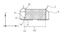
- FIG. 4 is a cross-sectional view of the 4-4 cross section of FIG. 2
- FIG. 5 is a cross-sectional view of the 5-5 cross section of FIG. 2
- FIG. 6 is a cross-sectional view of the 6-6 cross section of FIG. Is.
- the cross-sectional views of FIGS. 4 to 6 take a cross section in the vicinity of the hind foot portion, and each is a cross-sectional view of the toe side viewed from the heel side.
- 7 and 8 are schematic cross-sectional views of the midsole, both of which are cross-sectional views of the toe side viewed from the heel side.
- the midsole 4 includes a bulging portion 8 that bulges outward.
- the bulging portion 8 is formed, for example, by forming the side surface of the midsole 4 into a flare shape that expands outward from the upper side to the lower side.
- the bulging portion 8 so-called overpronation can be suppressed.
- the bulge 8 should be at least in the part corresponding to the hindfoot part on the inner foot side, or only in the part corresponding to the hindfoot part on the inner foot side. It is preferable to provide.
- Such a bulging portion 8 may be formed of the same material as the portion of the midsole 4 other than the bulging portion 8 and may have the same hardness.
- the bulging portion 8 may be formed of a material different from the portion other than the bulging portion of the midsole 4, and the hardness may be different between the bulging portion 8 and the portion other than the bulging portion 8.
- H1 the hardness of the bulging portion 8
- H2 H1> H2
- the midsole 4 is formed by two-color molding, and the bulging portion 8 and the portion other than the bulging portion 8 are integrally molded.
- the bulging portion 8 may be manufactured separately from the midsole 4 and joined to each other.
- the bulging portion 8 has the outer edge 12 of the bottom surface of the midsole 4 outside the joint portion 10 with reference to the joint portion 10 between the upper 2 and the midsole 4. It has a shape that is positioned.
- the bulging portion 8 is provided only in the portion corresponding to the hind foot portion on the inner foot side.
- the bulging portion 8 may be provided only on the hind foot portion on the inner foot side and the forefoot portion on the inner foot side.
- the bulging portion 8 may be provided only on the hindfoot portion on the inner foot side, the forefoot portion on the inner foot side, and the forefoot portion on the outer foot side.
- the bulging portion 8 may be provided in all the portions other than the portion corresponding to the landing region near the heel portion, which will be described later.
- the connecting portion 10 between the midsole 4 and the upper 2 which is a criterion for whether or not the bulging portion 8 is provided, may differ depending on the joining method between the midsole 4 and the upper 2. That is, when the midsole 4 and the upper 2 are sewn together, the midsole 4 and the upper 2 come into contact with each other on a surface, and the joint portion 10 has a certain width. In this case, based on the contact point between the midsole 4 and the upper 2, if the outer edge 12 of the bottom surface of the midsole 4 is outside the contact point between the midsole 4 and the upper 2, the midsole 4 has a bulging portion 8. Will have.
- the upper surface of the midsole 4 (the surface to which the upper 2 is connected) can be regarded as having a substantially flat shape even if it has some irregularities.
- the upper 2 has a curved shape that wraps around the instep. Therefore, in the cross sections shown in FIGS. 4 to 6, there is a contact point where the flat midsole 4 and the curved upper 2 are in contact with each other.
- the bulge 8 is provided on the midsole 4 by shaping the midsole 4 so that the outer edge 12 of the bottom surface of the midsole 4 is located outside the contact with reference to this contact.
- the height of the bulging portion 8 may be the same as the height of the midsole 4 (see FIG. 7) or lower than the height of the midsole 4 (see FIG. 8). It should be noted that FIGS. 7 and 8 show a schematic cross section of the midsole for clarification, and particularly exaggerate the angle of the inclined surface. When the height of the bulge 8 and the height of the midsole 4 match, the bulge 8 starts from the joint 10 between the midsole 4 and the upper 2 in the XZ cross section, for example, as shown in FIG. 7A.
- the bulging portion 8 has a shape formed of a vertical plane extending from the joint portion 10 between the midsole 4 and the upper along the YZ plane toward the bottom surface of the midsole 4. You may.
- the vertical plane may have an inclination of about ⁇ 3 ° with respect to the vertical direction. Further, as shown in FIG.
- the bulging portion 8 when the height of the bulging portion 8 and the height of the midsole 4 do not match, the bulging portion 8 is XZ orthogonal to the bulging direction (inner foot direction) of the bulging portion 8.
- the shape is a combination of a vertical surface extending along the YZ plane toward the bottom surface of the midsole 4 in a substantially vertical direction from the middle in the height direction of the midsole 4.
- the bulging portion 8 When the height of the bulging portion 8 is lower than that of the midsole 4, the bulging portion 8 has a shape of bulging toward the outside of the midsole 4 from an arbitrary position in the height direction of the midsole 4. .
- the upper end of the bulge 8 is in the middle in the height direction of the midsole 4, and the bulge 8 extends to the outside of the midsole 4 from the upper end toward the bottom surface of the midsole 4.
- the upper end of the bulging portion 8 is provided near the center in the height direction of the midsole 4.
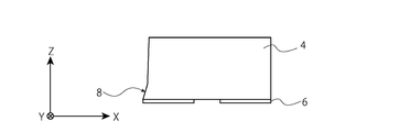
- FIG. 9 is a side view of the shoe.
- FIG. 9 is a side view of the shoe as viewed from the inner foot side, and a hatch is attached to a portion where a bulging portion is provided.
- the bulging portion 8 extends continuously in the front-rear direction from the middle of the midfoot portion to the hindfoot portion.
- the rear end of the bulging portion 8 is located in the middle of the hind foot portion and is defined so as not to cover the landing area described later.
- the height of the bulging portion 8 decreases toward the front.
- the upper side of the bulge 8 is inclined so as to move away from the upper end of the midsole 4 toward the front.
- the height of the bulging portion 8 may be changed depending on the site.
- the height of the bulging portion in the hind foot portion which is particularly required to be stable, may be increased and decreased toward the front side.
- the bulging portion 8 may have a discontinuous shape and may have a shape that intermittently extends in the front-rear direction.
- the outer edge 12 of the midsole 4 may coincide with the outer edge 14 of the outsole 6 having a ground contact surface when viewed from above.
- the fact that the outer edge 14 of the outsole 6 and the outer edge 12 of the midsole 4 match includes at least the following two patterns.
- the outsole 6 has one sheet shape, and the sheet shape matches the plane shape of the midsole 4, so that the outer edge 14 of the outsole 6 and the midsole 4 are viewed from above.
- the outer edges 12 of are matched.
- FIG. 10 is a top view of the outsole 6 and the midsole 4.
- the outer edge 14 of the outsole 6 is indicated by the alternate long and short dash line
- the outer edge 12 of the midsole 4 is indicated by the alternate long and short dash line
- the portion where the outer edges 12 and 14 of the outsole 6 and the midsole 4 coincide with each other is shown by a solid line. Shown. As shown in FIG. 10, only a part of the outer edge 14 of the island-shaped outsole 6 in the outer direction coincides with a part of the outer edge 12 of the midsole 4.
- the horizontal bulge length L1 (L1> 0) of the bulge portion 8 is the outer edge of the midsole 4 from the joint portion 10 of the upper 2 and the midsole 4 in the portion where the bulge portion 8 is not provided. It is longer than the horizontal length L2 (L2 ⁇ 0) up to 12.
- FIG. 11 is a top view of the midsole.
- the bulge length L1 of the bulge portion 8 is a horizontal distance from the joint portion 10 between the upper 2 and the midsole 4 to the outer edge 14 of the ground contact surface.
- the bulge length L1 of the bulge portion 8 is the coupling between the upper 2 and the midsole 4. It can be rephrased as the distance from the portion 10 to the outer edge 12 of the midsole 4.
- the horizontal length L2 of the portion where the bulging portion 8 is not provided is the horizontal distance from the joint portion 10 of the upper 2 and the midsole 4 to the outer edge 12 of the midsole 4.
- the horizontal length L2 may be measured at any portion where the bulging portion 8 is not provided.
- the bulge length L1 and the horizontal length L2 may change depending on the shape of the midsole 4 and the shape of the joint portion 10. In this case, it is preferable to take the bulge length L1 and the horizontal length L2 at the position where the distance in the horizontal direction is the largest, respectively, and compare them.
- the horizontal length L3 (L3 ⁇ 0) on the outer foot side is the horizontal distance from the joint portion 10 between the upper 2 and the midsole 4 on the outer foot side to the outer edge 14 of the ground contact surface.
- the bulge length L1 and the horizontal lengths L2 and L3 can be measured along the YZ plane at the position of the outer edge 12 of the midsole 4. Further, as an example, the bulge length L1 and the horizontal lengths L2 and L3 can be measured along the YZ plane at the position of the coupling portion 10. Further, as an example, an arbitrary point is taken at a position along the center line S in the hind legs, a line is drawn from the point toward the outer edge of the midsole, and the bulge length L1 and the horizontal length L2 are drawn along the line. , L3 may be measured.
- the bulge length L1 of the bulge portion 8 is larger than the horizontal lengths L2 and L3 from the joint portion 10 of the upper 2 and the midsole 4 of the portion where the bulge portion 8 is not provided to the outer edge 12 of the midsole 4. long.
- the outer edge 12 of the midsole 4 is on the inner foot side of the outer edge 14 of the ground contact surface, and the outer edge 12 of the midsole 4 However, it may be on the outer foot side of the outer edge 14 of the ground contact surface.
- the bulge length L1 and the horizontal length L2 are set in the horizontal direction from the joint portion 10 between the upper 2 and the midsole 4 to the outer edge 12 of the midsole 4 regardless of the position of the outer edge 14 of the ground contact surface. It may be a distance.
- the bulge length L1 and the horizontal length L2 are extended from the joint portion 10 between the upper 2 and the midsole 4 to the outer edge 14 of the ground contact surface regardless of the position of the outer edge 12 of the midsole 4. It may be a horizontal distance.
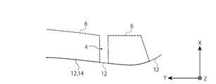
- FIG. 12 is a bottom view of the midsole and the outsole.
- the bulging portion 8 is not provided in the portion corresponding to the landing region 16 near the heel portion. Therefore, the portion where the bulging portion 8 is not provided is preferably a portion corresponding to the landing region 16 near the heel portion, and the horizontal length L2 is a portion corresponding to the landing region 16 near the heel portion. It is preferable to measure. Further, when the bulging portion 8 is not provided on the outer foot side, the horizontal length L2 may be measured at an arbitrary position on the outer foot side.
- the landing area 16 near the heel portion is an area of the bottom surface of the shoe 1 that first comes into contact with the ground when landing from the heel, and can be appropriately set according to the application of the shoe 1.
- the thickness of the midsole 4 is gradually reduced toward the heel side in the region posterior to the virtual line VL1 that crosses the vicinity of the calcaneus in the width direction as shown in FIG. ..
- the heel side and / or the outer foot side are inclined upward with respect to the horizontal direction in the vicinity of the heel to form an inclined surface (landing area 16).
- the shoe 1 according to the embodiment does not provide the bulging portion 8 in the portion corresponding to the landing area 16, but provides the bulging portion 8 in the portion other than the portion corresponding to the landing region 16. There is.
- the bulging portion 8 does not interfere with the grounding operation at the time of landing.
- the horizontal length L2 is preferably measured at the portion corresponding to the landing region 16, particularly at the rearmost portion on the heel side.
- the virtual line defining the landing area 16 may be a virtual line VL2 inclined in the front-rear direction instead of the virtual line VL1 described above.
- the virtual line VL2 is a virtual line that has the outer foot side more forward and the inner foot side more rearward and is inclined when viewed from above.
- the inclination angle of the virtual line VL2 can be arbitrarily set, and can be an angle larger than 0 degrees with respect to the virtual line VL1 up to about 45 degrees.
- the landing area 16 may be defined not only by inclining the bottom surface of the midsole 4 but also by arranging a plurality of outsoles 6 arranged in an island shape.
- the outsole 6 is not formed along the virtual line VL1 or the virtual line VL2, but the outsole 6 is formed in the front-rear direction of the virtual line VL1 or the virtual line VL2.
- a line in which the bottom surface of the midsole 4 is exposed can be formed between the outsole 6 along the virtual line VL1 or the virtual line VL2 (see, for example, FIG. 3).
- This line is a portion where the surface of the midsole 4 is exposed when the shoe 1 is viewed from the bottom, and is more flexible than the portion where the outsole 6 is formed. Therefore, the landing region 16 may be defined as the rear side of this line, and the bulging portion 8 may not be provided in the portion corresponding to the landing region 16 and the bulging portion 8 may be provided in other portions.
- the hardness of the midsole at least the portion corresponding to the hind foot portion, particularly the portion located below the calcaneus when worn is constant.
- the hardness near the end of the midsole on the inner foot side higher than the hardness of other parts to prevent the foot from falling to the inner foot side at the time of landing.
- the midsole has a difference in hardness, there is always a boundary between the high hardness portion and the low hardness portion. If the boundary is positioned so as to overlap the sole of the foot when viewed from above, the high hardness portion gives the wearer a so-called push-up feeling.
- overpronation can be suppressed by the bulging portion, so that overpronation can be suitably suppressed even if the hardness of the midsole is constant.
- FIG. 13 to 19 are cross-sectional views of shoes, and more specifically, are views showing a modified example of the cross-sectional shape of the bulging portion.
- the bulging portion 8 extends from the upper surface of the midsole 4 toward the bottom surface in a flare shape, and the inclination angle is gentle at an inflection point provided in the middle of the midsole 4 in the height direction. It extends like a flare.
- the bulging portion 8 extends from the middle in the height direction of the midsole 4 toward the inner foot side, and extends flare-like from there toward the bottom surface.
- the bulging portion 8 bulges toward the inner foot side with a curved shape from the middle in the height direction of the midsole 4.
- the bulging portion 8 bulges toward the inner foot side with a curved shape from a low position in the height direction of the midsole 4.
- a part of the midsole 4 other than the bulging portion 8 is formed of a high hardness material.
- the portion continuous with the bulging portion 8 is formed of a high hardness material, and the remaining portion is formed of a low hardness material.
- the portion formed of the high hardness material is hatched.
- the bulging portion 8 has the same shape as the bulging portion shown in FIG. Further, in the example shown in FIG.
- the bulging portion 8 has a high hardness material portion having a shape symmetrical with respect to the boundary line between the bulging portion 8 and the portion of the midsole 4 other than the bulging portion 8. doing.
- the bulging portion 8 is formed over the entire length of the midsole 4 in the height direction.
- This example also has a high hardness material portion having a shape line-symmetrical with the bulging portion 8.
- the bulging portion 8 is formed over the entire length of the midsole 4 in the height direction and is curved toward the inner foot side.
- This example also has a high hardness material portion having a shape line-symmetrical with the bulging portion 8.
- the high-hardness material portion extends inward of the midsole only to a position where it hardly overlaps the calcaneus when viewed from above.
- the high-hardness material portion extends to a position where it partially overlaps with the calcaneus when viewed from above.
- the feeling of pushing up can be suppressed.
- the high hardness material portion when the high hardness material portion is extended in the medial direction of the midsole 4, it is preferable to extend only the lower side in the height direction so that only the upper side in the height direction does not overlap with the calcaneus. In this case, for example, it is more preferable to provide the high hardness material portion below the center in the height direction. Further, in order to preferably prevent the feeling of pushing up, it is more preferable that the high hardness material portion does not have a shape that forms an upper corner at a position where it overlaps with the calcaneus. With such a high hardness material portion, the feeling of pushing up can be suppressed.
- the high hardness material portion does not necessarily have to have a shape line-symmetrical with the bulging portion 8.
- the bulging portion 8 at the position corresponding to the hind foot portion on the inner foot side, the inner foot side can be firmly supported at the time of landing, and overpronation can be suppressed. This can improve stability. Further, by not providing the bulging portion 8 in the landing region 16, it is possible to prevent the bulging portion 8 from hindering the landing operation.
- the bulging portion is provided on the midsole, but in the second embodiment, the bulging portion is provided on the outsole.
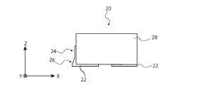
- FIG. 20 is a cross-sectional view of the shoe.
- the outsole 22 of the shoe 20 has a winding portion 24, and the bulging portion 26 is formed in the winding portion 24.
- the winding portion 24 is formed by a peripheral wall that rises upward from the outer edge of the outsole 22. More specifically, the winding portion 24 extends upward from the outer edge of the outsole 22.
- the winding portion 24 improves the rigidity of the shoe 20.
- the rigidity of the shoe 20 means bending rigidity or torsional rigidity. The position of the upper end of the winding portion 24 can be appropriately changed according to the use of the shoe 20.
- the height of the winding portion 24 may be uniform or may differ depending on the position. For example, when rigidity is required on the toe side, the winding portion 24 may be lowered on the heel side and raised on the toe side, or the height may be changed inside and outside in the width direction.
- the bulging portion 26 is formed by forming the side surface of the outsole 22 into a flare shape that expands outward from the upper side to the lower side. The so-called overpronation can also be suppressed by such a bulging portion 26.
- the winding portion 24 may be formed on the entire circumference of the outsole 22 along the outer edge of the outsole 22, or may be formed only partially along the outer edge of the outsole 22.
- the bulging portion 26 may be formed on all the winding portions 24 along the outer edge of the outsole 22, or may be formed only on a part thereof.
- the bulging portion 26 may be provided only on the portion corresponding to the hind foot portion on the inner foot side.
- the bulging portion 26 may be provided only on the hind foot portion on the inner foot side and the forefoot portion on the inner foot side. In a further aspect, the bulging portion 26 may be provided only on the hindfoot portion on the inner foot side, the forefoot portion on the inner foot side, and the forefoot portion on the outer foot side. Further, in a further aspect, the bulging portion 26 may be provided in all the portions other than the portion corresponding to the landing region near the heel portion.
- the height of the bulging portion 26 may be the same as the height of the hoisting portion 24, or may be lower than the hoisting portion 24.
- the height of the winding portion 24 and the height of the midsole 28 may match, and the height of the bulging portion 26 and the height of the winding portion 24 may match.
- the bulging portion 26 has a horizontal plane extending along the XY plane from the upper end of the winding portion 24 toward the outside of the midsole 28 in a YZ cross section orthogonal to the bulging direction of the bulging portion 26, and an end of the horizontal plane.
- the shape is a combination of a vertical surface extending from the sole 28 toward the bottom surface of the midsole 28 along the YZ plane.
- 21 to 23 are cross-sectional views of shoes, and are views showing deformation examples of the bulging portion.
- the bulging portion 26 is the winding portion 24. It has a shape that bulges toward the outside of the winding portion 24 from an arbitrary position in the height direction of.
- the height of the winding portion 24 may be lower than the height of the midsole 28, and the height of the bulging portion 26 and the height of the winding portion 24 may match.
- the bulging portion 26 has a horizontal plane extending along the XY plane from the upper end of the winding portion 24 toward the outside of the midsole 28 in a YZ cross section orthogonal to the bulging direction of the bulging portion 26, and an end of the horizontal plane.
- the shape is a combination of a vertical surface extending from the sole 22 toward the bottom surface of the outsole 22 substantially along the YZ plane. As shown in FIG. 23, when the height of the winding portion 24 is lower than the height of the midsole 28 and the height of the bulging portion 26 is lower than the height of the winding portion 24, the bulging portion 26 is the winding portion.
- the shape is such that it bulges outward from the winding portion 24 from an arbitrary position in the height direction of the 24.
- the bulging portion 26 by providing the bulging portion 26, the inner foot side can be firmly supported at the time of landing and overpronation can be suppressed. This can improve stability. Further, by not providing the bulging portion 26 in the landing region, it is possible to prevent the bulging portion 26 from hindering the landing operation.
- the first aspect comprises an outsole with a ground contact surface, a midsole fixed on the outsole, and an upper coupled to the midsole along the periphery of the midsole, with the midsole on the inner foot side.
- a bulge is provided at a position corresponding to the hind foot, and the bulge is measured by the horizontal distance from the joint between the upper and the midsole to the outer edge of the ground contact surface when viewed from above. It has a bulge length L1 and the bulge length L1 is longer than the horizontal length L2 from the joint between the upper and the midsole at the rearmost end to the outer edge of the midsole.
- the hardness of the midsole is constant at least in the portion supporting the calcaneus.
- the hardness of the bulging portion is higher than the hardness of the portion other than the bulging portion of the midsole.
- the bulging portion is formed from the joint surface between the midsole and the outsole to the middle in the height direction of the midsole.
- the side surface of the bulging portion on the inner foot side has a shape that moves away from the joint portion toward the ground contact surface.
- the midsole is molded in two colors.
- the bulging portion is formed only on the hindfoot portion on the inner foot side.
- the bulging portion is formed at a position other than the outer periphery of the landing region near the heel portion of the ground contact surface.
- a ninth aspect comprises an outsole with a ground contact surface, a midsole fixed on the outsole, and an upper coupled to the midsole along the periphery of the midsole, with the outsole on the inner foot side.
- a bulge is provided at a position corresponding to the hind foot, and the bulge is measured by the horizontal distance from the joint between the outsole and the midsole to the outer edge of the ground contact surface when viewed from above. It has a protrusion length L1 and the bulge length L1 is longer than the horizontal length L2 from the joint between the upper and the midsole to the outer edge of the midsole at the rearmost end.
- the present invention can be used for shoes.
Abstract
A shoe 1 comprises an outsole 6 having a ground contact surface, a midsole 4 secured on the outsole 6, and an upper bonded to the midsole 4 along the peripheral edge of the midsole 4, the midsole 4 comprising a bulge section 8 in a position corresponding to an inner-foot-side rear foot section, the bulge section 8 having a bulge length L1 measured in terms of the horizontal distance from the bond 10 between the upper and the midsole 4 to an outer edge 14 of the ground contact surface in a top surface view, and the bulge length L1 being greater than the horizontal length L2 at the rearmost end from the bond 10 between the upper and the midsole 4 to the outer edge 12 of the midsole 4.
Description
本発明は、シューズに関し、特に安定性を高めたシューズに関する。
The present invention relates to shoes, and particularly to shoes with improved stability.
従来、ランニングやウォーキングで用いられるシューズにおいては、着地時の衝撃を吸収するクッション性と、着地時の安定性との両立が求められている。特に着地時の安定性は、怪我を抑制する観点で重要視されており、シューズの安定性が低いと着地時に足が内足側に傾きすぎるいわゆるオーバープロネーションを起こし、怪我の可能性を高める。したがって、オーバープロネーションを抑制することは極めて重要であり、これを実現するための技術として例えば特許文献1に記載されたものが知られている。
Conventionally, shoes used for running and walking are required to have both cushioning properties that absorb the impact at the time of landing and stability at the time of landing. In particular, stability at the time of landing is regarded as important from the viewpoint of suppressing injuries, and if the stability of the shoes is low, the foot tilts too much toward the inner foot at the time of landing, causing so-called overpronation, increasing the possibility of injury. .. Therefore, it is extremely important to suppress overpronation, and as a technique for realizing this, for example, the one described in Patent Document 1 is known.
しかしながら、特許文献1に記載されたシューズは、ミッドソールに硬質な埋没部を設けており安定性が高いが、ユーザーの好みによっては突き上げ感が気になる場合がある。したがって、特許文献1とは異なる手段で安定性を高めるニーズが存在する。
However, the shoes described in Patent Document 1 have a hard buried portion in the midsole and are highly stable, but the feeling of pushing up may be anxious depending on the user's preference. Therefore, there is a need to improve stability by means different from those of Patent Document 1.
そこで本発明は上記課題を解決するためになされたものであり、安定性をさらに高めるシューズを提供することを目的とする。
Therefore, the present invention has been made to solve the above problems, and an object of the present invention is to provide shoes that further enhance stability.
本発明の第一の態様によれば、接地面を有するアウトソールと、アウトソール上に固定されたミッドソールと、ミッドソールの周縁に沿ってミッドソールに結合されたアッパーとを備え、ミッドソールは、内足側の後足部に対応する位置に膨出部を備え、膨出部は、上面視したときに、アッパーとミッドソールとの結合部から、接地面の外縁までの間の水平距離で測定された膨出長さL1を有し、膨出長さL1は、最後端におけるアッパーとミッドソールの結合部からミッドソールの外縁までの水平長さL2よりも長い。
According to a first aspect of the present invention, the midsole comprises an outsole having a ground contact surface, a midsole fixed on the outsole, and an upper coupled to the midsole along the periphery of the midsole. Has a bulge at a position corresponding to the hind foot on the inner foot side, and the bulge is horizontal from the joint between the upper and the midsole to the outer edge of the ground contact surface when viewed from above. It has a bulge length L1 measured at a distance, and the bulge length L1 is longer than the horizontal length L2 from the joint between the upper and the midsole at the rearmost end to the outer edge of the midsole.
本発明の異なる態様は、接地面を有するアウトソールと、アウトソール上に固定されたミッドソールと、ミッドソールの周縁に沿って当該ミッドソールに結合されたアッパーとを備え、記アウトソールは、内足側の後足部に対応する位置に膨出部を備え、膨出部は、上面視したときに、アウトソールとミッドソールとの結合部から、接地面の外縁までの水平距離で測定された膨出長さL1を有し、膨出長さL1は、最後端における、アッパーとミッドソールの結合部からミッドソールの外縁までの水平長さL2よりも長い。
A different aspect of the present invention comprises an outsole having a ground plane, a midsole fixed on the outsole, and an upper coupled to the midsole along the periphery of the midsole. A bulge is provided at a position corresponding to the hind foot on the inner foot side, and the bulge is measured by the horizontal distance from the joint between the outsole and the midsole to the outer edge of the ground contact surface when viewed from above. It has a bulge length L1 and the bulge length L1 is longer than the horizontal length L2 at the rearmost end from the joint between the upper and the midsole to the outer edge of the midsole.
まず、本明細書で用いる用語の定義について説明する。本明細書では、方向を示す用語として、前後方向、幅方向、及び上下方向を用いることがあるが、これら方向を示す用語は、シューズを平らな面に置き、シューズを着用したときの着用者の視点から見た方向を示す。したがって、前方向はつま先側を意味し、後方向はかかと側を意味する。また、方向を示す用語として、内足側、及び外足側を用いることがあるが、内足側とは足の幅方向内側、即ち足の縦アーチが設けられている側を意味し、外足側とは幅方向において内足側とは反対側を意味する。
First, the definitions of terms used in this specification will be described. In the present specification, the terms indicating the direction may be used in the front-rear direction, the width direction, and the vertical direction, and the terms indicating these directions are used when the shoe is placed on a flat surface and the wearer wears the shoe. Indicates the direction seen from the viewpoint of. Therefore, the forward direction means the toe side, and the rear direction means the heel side. In addition, as terms indicating the direction, the inner foot side and the outer foot side may be used, but the inner foot side means the inner side in the width direction of the foot, that is, the side where the vertical arch of the foot is provided, and is the outer side. The foot side means the side opposite to the inner foot side in the width direction.
また、以下の説明では、シューズのミッドソール及びアウトソールの外縁について言及することがあるが、ミッドソール又はアウトソールの外縁とは、ミッドソール又はアウトソールをそれぞれ上面視したときの投影形状の外縁を意味する。また、以下の説明では、ミッドソールの外側(方向)又は内側(方向)について言及することがある。ミッドソールの外側はミッドソールを上面視したときに、ミッドソールの面から離れるあらゆる方向を意味する。ミッドソールの内側はミッドソールを上面視したときに、ミッドミッドソールの外側からミッドソールの面内に向かうあらゆる方向を意味する。さらにまた、幾つかの例では、3次元直交座標を用いて方向を説明することがある。この場合、X軸は内足側から外足側に向けて延び、Y軸は踵側からつま先側に向けて延び、Z軸は底面側から上側に向けて延びる。
Further, in the following description, the outer edge of the midsole and the outsole of the shoe may be referred to, but the outer edge of the midsole or the outsole is the outer edge of the projected shape when the midsole or the outsole is viewed from above. Means. Further, in the following description, the outside (direction) or the inside (direction) of the midsole may be referred to. The outside of the midsole means any direction away from the surface of the midsole when the midsole is viewed from above. The inside of the midsole means any direction from the outside of the midsole to the inside of the surface of the midsole when the midsole is viewed from above. Furthermore, in some examples, directions may be described using three-dimensional Cartesian coordinates. In this case, the X-axis extends from the inner foot side toward the outer foot side, the Y-axis extends from the heel side toward the toe side, and the Z-axis extends from the bottom surface side toward the upper side.
また、実施形態によるシューズの説明を行う前に、実施形態によるシューズと関連することがある足の骨格について、図1を参照しながら説明を行う。
Further, before explaining the shoes according to the embodiment, the skeleton of the foot that may be related to the shoes according to the embodiment will be explained with reference to FIG.
図1は、足の骨格を示す上面図である。人体の足は、主に、楔状骨Ba、立方骨Bb、舟状骨Bc、距骨Bd、踵骨Be、中足骨Bf、趾骨Bgで構成される。足の関節には、MP関節Ja、リスフラン関節Jb、ショパール関節Jcが含まれる。ショパール関節Jcには、立方骨Bbと踵骨Beがなす踵立方関節Jc1と、舟状骨Bcと距骨Bdがなす距舟関節Jc2とが含まれる。本明細書での着用者の「前足部」は、MP関節Jaよりも前側の部分をいい、つま先側から測定して足の全長の0~約30%をいう。また、「中足部」は、MP関節Jaからショパール関節Jcまでの部分をいい、つま先側から測定して足の全長の約30~80%をいう。また、「後足部」は、ショパール関節Jcよりも後側の部分をいい、つま先側から測定して足の全長の約80~100%をいう。また、図1において中心線Sは、シューズの中心線を示し、足幅方向中央部に沿って延びる。中心線Sは、人体の第三中足骨Bf3と踵骨Beの踵骨隆起内側突起Be1を通る直線上に位置する部位を想定している。図1では踵骨隆起内側突起Be1が位置すると想定される範囲を示す。
FIG. 1 is a top view showing the skeleton of the foot. The foot of the human body is mainly composed of cuneiform bone Ba, cuboid bone Bb, scaphoid bone Bc, talus bone Bd, calcaneus bone Be, metatarsal bone Bf, and phalange bone Bg. The joints of the foot include MP joint Ja, Lisfranc joint Jb, and Chopard joint Jc. The Chopard joint Jc includes a calcaneus cubic joint Jc1 formed by a cuboid bone Bb and a calcaneus Be, and a talus joint Jc2 formed by a scaphoid bone Bc and a talus Bd. The "forefoot portion" of the wearer in the present specification refers to the portion on the anterior side of the MP joint Ja, and refers to 0 to about 30% of the total length of the foot measured from the toe side. The "metatarsal portion" refers to the portion from the MP joint Ja to the Chopard joint Jc, and refers to about 30 to 80% of the total length of the foot measured from the toe side. The "rear foot portion" refers to a portion posterior to the Chopard joint Jc, and refers to about 80 to 100% of the total length of the foot measured from the toe side. Further, in FIG. 1, the center line S indicates the center line of the shoe and extends along the central portion in the foot width direction. The center line S assumes a portion located on a straight line passing through the third metatarsal bone Bf3 of the human body and the medial protrusion Be1 of the calcaneus ridge of the calcaneus Be. FIG. 1 shows the range where the medial process Be1 of the calcaneal ridge is assumed to be located.
図2は、シューズの側面図である。図2は、片方のシューズを内足側から見た側面図である。図2に示すように、シューズ1は、主として足の甲を覆うアッパー2と、アッパー2が結合されているミッドソール4と、歩行時に地面に接触する接地面を有するアウトソール6と、を備えている。
FIG. 2 is a side view of the shoe. FIG. 2 is a side view of one shoe as viewed from the inner foot side. As shown in FIG. 2, the shoe 1 includes an upper 2 that mainly covers the instep, a midsole 4 to which the upper 2 is connected, and an outsole 6 that has a ground contact surface that contacts the ground during walking. ing.
アッパー2は、足の甲の上側を覆う形状を有している。アッパー2は、アッパー本体2aと、アッパーの緊締手段(緊締構造)2bと、アッパー2の幅方向中央付近においてアッパー2の前後方向に延びるスリット2cとを備えている。また、アッパー2にはシュータン2dが取り付けられている。本実施形態では、緊締手段2bとして、ハトメと、シューレースとの組み合わせによる構造を採用しているが、緊締手段としては面ファスナー等を用いてもよい。
The upper 2 has a shape that covers the upper side of the instep. The upper 2 includes an upper main body 2a, a tightening means (tightening structure) 2b of the upper, and a slit 2c extending in the front-rear direction of the upper 2 near the center in the width direction of the upper 2. Further, a tongue 2d is attached to the upper 2. In the present embodiment, the tightening means 2b adopts a structure in which eyelets and shoelaces are combined, but a surface fastener or the like may be used as the tightening means.
アッパー本体2aは、例えばポリエステル、ポリウレタン等の合成繊維を編んだメッシュ素材、合成皮革、天然皮革によって形成され、足の甲を覆う形状を有している。スリット2cは、シューレースの締め具合によってアッパー本体2aの幅を調整するための緩衝部分である。スリット2cの幅方向両側には、複数のハトメが設けられている。スリットからはシュータン2dが露出しており、シューレースを付けた際にシューレースが着用者の足の甲に接触しないようになっている。
The upper body 2a is formed of a mesh material woven from synthetic fibers such as polyester and polyurethane, synthetic leather, and natural leather, and has a shape that covers the instep. The slit 2c is a cushioning portion for adjusting the width of the upper body 2a according to the tightening condition of the shoelace. A plurality of eyelets are provided on both sides of the slit 2c in the width direction. The tongue 2d is exposed from the slit so that the laces do not come into contact with the instep of the wearer when the laces are attached.
図3は、シューズの底面図である。図3に示すように、アウトソール6は、例えばラバーを所定形状に成形することで形成されている。アウトソール6は、ミッドソール4の底面を少なくとも部分的に覆うように、ミッドソール4の底面に貼り付けられている。アウトソール6は、地面に接触する接地面を有する。接地面の表面には所定の凹凸パターンが形成されており、凹凸パターンによりグリップを向上させる。
FIG. 3 is a bottom view of the shoes. As shown in FIG. 3, the outsole 6 is formed, for example, by molding rubber into a predetermined shape. The outsole 6 is attached to the bottom surface of the midsole 4 so as to cover the bottom surface of the midsole 4 at least partially. The outsole 6 has a ground contact surface that contacts the ground. A predetermined uneven pattern is formed on the surface of the ground contact surface, and the uneven pattern improves the grip.
図3に示す例では、アウトソール6は、複数の島状部分を所定のミッドソールの底面の所定位置に貼り付けて形成されている。接地面は、複数の島状部分の底面によって形成されており、島状部分の間からミッドソール4の底面が露出している。したがって、図示の例では接地面は、1つの連続する面を形成しておらず、複数の面によって形成されている。なお、アウトソール6を1枚の平らなシート状部材によって形成してもよい。この場合、シート状部材の底面が接地面を形成する。
In the example shown in FIG. 3, the outsole 6 is formed by attaching a plurality of island-shaped portions to predetermined positions on the bottom surface of a predetermined midsole. The ground contact surface is formed by the bottom surfaces of a plurality of island-shaped portions, and the bottom surface of the midsole 4 is exposed between the island-shaped portions. Therefore, in the illustrated example, the ground plane does not form one continuous plane, but is formed by a plurality of planes. The outsole 6 may be formed of a single flat sheet-like member. In this case, the bottom surface of the sheet-like member forms a ground plane.
ミッドソール4は、衝撃を吸収する役割を果たし、例えば発泡EVA、発泡ウレタン、GEL、コルクのような衝撃を吸収する材料によって形成される。ミッドソール4は、足を上面視したときの投影形状を模した平面形状を有している。ミッドソール4の上面は、足の裏の凹凸形状に対応する凹凸形状を有している。また、ミッドソール4の上面には、アッパー2が結合される。より具体的にはアッパー2は、ミッドソール4の外縁に沿って、又は外縁よりも僅かにミッドソール4の内側に沿って結合されている。アッパー2をミッドソール4に結合する手段としては、アッパー2の縁をミッドソール4に縫い付けたり、接着剤等の接合手段を用いて結合したりする方法がある。ミッドソール4の形状や厚さは、シューズの用途に応じて適宜設定できる。
The midsole 4 plays a role of absorbing impact, and is formed of an impact absorbing material such as foamed EVA, urethane foam, GEL, and cork. The midsole 4 has a planar shape that imitates the projected shape when the foot is viewed from above. The upper surface of the midsole 4 has an uneven shape corresponding to the uneven shape of the sole of the foot. Further, the upper 2 is coupled to the upper surface of the midsole 4. More specifically, the upper 2 is joined along the outer edge of the midsole 4 or slightly along the inside of the midsole 4 than the outer edge. As a means for connecting the upper 2 to the midsole 4, there are a method of sewing the edge of the upper 2 to the midsole 4 or a method of joining using a joining means such as an adhesive. The shape and thickness of the midsole 4 can be appropriately set according to the intended use of the shoe.
図4~図6は、シューズの断面図を示す。より具体的には図4は図2の4-4断面の断面図であり、図5は図2の5-5断面の断面図であり、図6は図2の6-6断面の断面図である。図4~図6の断面図は、後足部付近の断面をとっており、いずれもかかと側からつま先側を見た断面図である。図7及び図8は、ミッドソールの概略断面図であり、いずれもかかと側からつま先側を見た断面図である。
4 to 6 show cross-sectional views of shoes. More specifically, FIG. 4 is a cross-sectional view of the 4-4 cross section of FIG. 2, FIG. 5 is a cross-sectional view of the 5-5 cross section of FIG. 2, and FIG. 6 is a cross-sectional view of the 6-6 cross section of FIG. Is. The cross-sectional views of FIGS. 4 to 6 take a cross section in the vicinity of the hind foot portion, and each is a cross-sectional view of the toe side viewed from the heel side. 7 and 8 are schematic cross-sectional views of the midsole, both of which are cross-sectional views of the toe side viewed from the heel side.
図4~図6に示すように、ミッドソール4は、外側に向けて膨出する膨出部8を備える。膨出部8は、例えば、ミッドソール4の側面を、上側から下側に向かうにつれて外側に広がるフレア形状とすることで形成される。膨出部8を設けることにより、いわゆるオーバープロネーションを抑制できる。オーバープロネーションを最大限に抑制できるようにするためには、膨出部8を、少なくとも内足側の後足部に相当する部分に、又は内足側の後足部に相当する部分にのみ設けることが好ましい。このような膨出部8は、ミッドソール4の膨出部8以外の部分と同一の材料により形成され、同一の硬度を有していてもよい。また、膨出部8を、ミッドソール4の膨出部以外の部分と異なる材料により形成し、膨出部8と、膨出部8以外の部分とで硬度を異ならせてもよい。例えば、図4~図6に示すように、膨出部8の硬度をH1とし、膨出部8以外の部分の硬度をH2とした場合、H1>H2とすることができる。このような構成とすることで、安定性を向上しつつ、突上げ感を抑制できる。このような場合、ミッドソール4を二色成形により形成し、膨出部8と、膨出部8以外の部分とを一体成形することが好ましい。また、膨出部8をミッドソール4と別体で作製し、これらを接合してもよい。
As shown in FIGS. 4 to 6, the midsole 4 includes a bulging portion 8 that bulges outward. The bulging portion 8 is formed, for example, by forming the side surface of the midsole 4 into a flare shape that expands outward from the upper side to the lower side. By providing the bulging portion 8, so-called overpronation can be suppressed. In order to maximize the suppression of overpronation, the bulge 8 should be at least in the part corresponding to the hindfoot part on the inner foot side, or only in the part corresponding to the hindfoot part on the inner foot side. It is preferable to provide. Such a bulging portion 8 may be formed of the same material as the portion of the midsole 4 other than the bulging portion 8 and may have the same hardness. Further, the bulging portion 8 may be formed of a material different from the portion other than the bulging portion of the midsole 4, and the hardness may be different between the bulging portion 8 and the portion other than the bulging portion 8. For example, as shown in FIGS. 4 to 6, when the hardness of the bulging portion 8 is H1 and the hardness of the portion other than the bulging portion 8 is H2, H1> H2 can be obtained. With such a configuration, it is possible to suppress the feeling of pushing up while improving the stability. In such a case, it is preferable that the midsole 4 is formed by two-color molding, and the bulging portion 8 and the portion other than the bulging portion 8 are integrally molded. Further, the bulging portion 8 may be manufactured separately from the midsole 4 and joined to each other.
別の観点で説明すると、膨出部8は、上面視したときに、アッパー2とミッドソール4との結合部10を基準として、ミッドソール4の底面の外縁12が結合部10よりも外側に位置するような形状を有している。実施形態によるシューズ1では、内足側の後足部に対応する部分にのみ膨出部8が設けられている。なお他の態様では、内足側の後足部及び内足側の前足部にのみ膨出部8を設けてもよい。更なる態様では、内足側の後足部、内足側の前足部、及び外足側の前足部にのみ膨出部8を設けてもよい。また、更なる態様では、後述する踵部近傍の着地領域に対応する部分以外の全ての部分に膨出部8を設けてもよい。
From another point of view, when viewed from above, the bulging portion 8 has the outer edge 12 of the bottom surface of the midsole 4 outside the joint portion 10 with reference to the joint portion 10 between the upper 2 and the midsole 4. It has a shape that is positioned. In the shoe 1 according to the embodiment, the bulging portion 8 is provided only in the portion corresponding to the hind foot portion on the inner foot side. In another aspect, the bulging portion 8 may be provided only on the hind foot portion on the inner foot side and the forefoot portion on the inner foot side. In a further aspect, the bulging portion 8 may be provided only on the hindfoot portion on the inner foot side, the forefoot portion on the inner foot side, and the forefoot portion on the outer foot side. Further, in a further aspect, the bulging portion 8 may be provided in all the portions other than the portion corresponding to the landing region near the heel portion, which will be described later.
ここで、膨出部8が設けられているか否かの基準となるミッドソール4とアッパー2の結合部10は、ミッドソール4とアッパー2との結合方法によって異なる場合がある。つまり、ミッドソール4とアッパー2とが縫合されている場合、ミッドソール4とアッパー2は、面で接することとなり、結合部10が一定の幅を有する。この場合、ミッドソール4とアッパー2との接点を基準とし、ミッドソール4とアッパー2の接点よりも外側にミッドソール4の底面の外縁12がある場合には、ミッドソール4は膨出部8を有していることとなる。ミッドソール4の上面(アッパー2が結合される面)は、多少の凹凸を有しているとしてもほぼ平坦な形状を有するものとみなすことができる。これに対してアッパー2は、図4~図6に示すように、足の甲を包み込めるような湾曲形状を有している。したがって、図4~図6に示す断面においては、平らなミッドソール4と湾曲形状のアッパー2とが接する接点が存在する。この接点を基準として、ミッドソール4の底面の外縁12が、接点よりも外側に位置するようにミッドソール4を形付けることで、ミッドソール4に膨出部8を設けられる。
Here, the connecting portion 10 between the midsole 4 and the upper 2, which is a criterion for whether or not the bulging portion 8 is provided, may differ depending on the joining method between the midsole 4 and the upper 2. That is, when the midsole 4 and the upper 2 are sewn together, the midsole 4 and the upper 2 come into contact with each other on a surface, and the joint portion 10 has a certain width. In this case, based on the contact point between the midsole 4 and the upper 2, if the outer edge 12 of the bottom surface of the midsole 4 is outside the contact point between the midsole 4 and the upper 2, the midsole 4 has a bulging portion 8. Will have. The upper surface of the midsole 4 (the surface to which the upper 2 is connected) can be regarded as having a substantially flat shape even if it has some irregularities. On the other hand, as shown in FIGS. 4 to 6, the upper 2 has a curved shape that wraps around the instep. Therefore, in the cross sections shown in FIGS. 4 to 6, there is a contact point where the flat midsole 4 and the curved upper 2 are in contact with each other. The bulge 8 is provided on the midsole 4 by shaping the midsole 4 so that the outer edge 12 of the bottom surface of the midsole 4 is located outside the contact with reference to this contact.
膨出部8の高さは、ミッドソール4の高さと一致していても良いし(図7参照)、ミッドソール4よりも低くてもよい(図8参照)。なお、図7及び図8は、明確化のためにミッドソールの断面を概略的に示したものであり、特に傾斜面の角度を誇張して示す。膨出部8の高さとミッドソール4の高さが一致する場合、膨出部8は、例えば図7(a)に示すように、XZ断面において、ミッドソール4とアッパー2の結合部10からミッドソール4の外側に向けて水平方向に、XY平面に沿って延びる水平面と、水平面の端からほぼ鉛直方向にミッドソール4の底面に向けてYZ平面に沿って延びる鉛直面とを組み合わせた形状となる。また、膨出部8は、図7(b)に示すように、ミッドソール4とアッパーの結合部10から、ミッドソール4の底面に向けてYZ平面に沿って延びる鉛直面からなる形状であってもよい。鉛直面は、鉛直方向に対して±3°程度の傾斜を有していてもよい。また、図8に示すように、膨出部8の高さとミッドソール4の高さが一致しない場合、膨出部8は、膨出部8の膨出方向(内足方向)と直交するXZ断面において、ミッドソール4の高さ方向中間からほぼ鉛直方向にミッドソール4の底面に向けてYZ平面に沿って延びる鉛直面とを組み合わせた形状となる。
The height of the bulging portion 8 may be the same as the height of the midsole 4 (see FIG. 7) or lower than the height of the midsole 4 (see FIG. 8). It should be noted that FIGS. 7 and 8 show a schematic cross section of the midsole for clarification, and particularly exaggerate the angle of the inclined surface. When the height of the bulge 8 and the height of the midsole 4 match, the bulge 8 starts from the joint 10 between the midsole 4 and the upper 2 in the XZ cross section, for example, as shown in FIG. 7A. A shape that combines a horizontal plane extending horizontally along the XY plane toward the outside of the midsole 4 and a vertical plane extending substantially vertically from the edge of the horizontal plane along the YZ plane toward the bottom surface of the midsole 4. It becomes. Further, as shown in FIG. 7B, the bulging portion 8 has a shape formed of a vertical plane extending from the joint portion 10 between the midsole 4 and the upper along the YZ plane toward the bottom surface of the midsole 4. You may. The vertical plane may have an inclination of about ± 3 ° with respect to the vertical direction. Further, as shown in FIG. 8, when the height of the bulging portion 8 and the height of the midsole 4 do not match, the bulging portion 8 is XZ orthogonal to the bulging direction (inner foot direction) of the bulging portion 8. In the cross section, the shape is a combination of a vertical surface extending along the YZ plane toward the bottom surface of the midsole 4 in a substantially vertical direction from the middle in the height direction of the midsole 4.
膨出部8の高さが、ミッドソール4よりも低い場合、膨出部8は、ミッドソール4の高さ方向の任意の位置からミッドソール4の外側に向けて膨出させた形状となる。例えば図4~6に示す例では膨出部8の上端は、ミッドソール4の高さ方向中間にあり、膨出部8は上端からミッドソール4の底面に向かうにつれてミッドソール4の外側に広がる形状を有する。この場合において、膨出部8の上端は、ミッドソール4の高さ方向の中央付近に設けられていることがより好ましい。
When the height of the bulging portion 8 is lower than that of the midsole 4, the bulging portion 8 has a shape of bulging toward the outside of the midsole 4 from an arbitrary position in the height direction of the midsole 4. .. For example, in the examples shown in FIGS. 4 to 6, the upper end of the bulge 8 is in the middle in the height direction of the midsole 4, and the bulge 8 extends to the outside of the midsole 4 from the upper end toward the bottom surface of the midsole 4. Has a shape. In this case, it is more preferable that the upper end of the bulging portion 8 is provided near the center in the height direction of the midsole 4.
図9は、シューズの側面図である。図9は、内足側から見たシューズの側面図であり、膨出部が設けられている部分にハッチングを付してある。図9に示す例では、膨出部8は、中足部中間から後足部にかけて、前後方向において連続して延びている。膨出部8の後端は、後足部の中間にあり、後述する着地領域にかからないように定められている。また、図9に示す例では、膨出部8の高さが、前方に向かうにつれて低くなっている。図示の例では、膨出部8の上辺が、前方に向かうにつれてミッドソール4の上端から離れるように傾斜している。このように、膨出部8の高さを部位によって変化させてもよい。この場合、特に安定性が要求される後足部における膨出部の高さを高くし、前側に向かうにつれて低くしてもよい。また、変形例として、膨出部8を不連続形状とし、前後方向に断続的に延びる形状としてもよい。
FIG. 9 is a side view of the shoe. FIG. 9 is a side view of the shoe as viewed from the inner foot side, and a hatch is attached to a portion where a bulging portion is provided. In the example shown in FIG. 9, the bulging portion 8 extends continuously in the front-rear direction from the middle of the midfoot portion to the hindfoot portion. The rear end of the bulging portion 8 is located in the middle of the hind foot portion and is defined so as not to cover the landing area described later. Further, in the example shown in FIG. 9, the height of the bulging portion 8 decreases toward the front. In the illustrated example, the upper side of the bulge 8 is inclined so as to move away from the upper end of the midsole 4 toward the front. In this way, the height of the bulging portion 8 may be changed depending on the site. In this case, the height of the bulging portion in the hind foot portion, which is particularly required to be stable, may be increased and decreased toward the front side. Further, as a modification, the bulging portion 8 may have a discontinuous shape and may have a shape that intermittently extends in the front-rear direction.
ミッドソール4とアウトソール6との形状によっては、ミッドソール4の外縁12は、上面視したときに接地面を有するアウトソール6の外縁14と一致する場合がある。ここで、アウトソール6の外縁14と、ミッドソール4の外縁12が一致する、とは、少なくとも以下の2つのパターンを含む。
Depending on the shape of the midsole 4 and the outsole 6, the outer edge 12 of the midsole 4 may coincide with the outer edge 14 of the outsole 6 having a ground contact surface when viewed from above. Here, the fact that the outer edge 14 of the outsole 6 and the outer edge 12 of the midsole 4 match includes at least the following two patterns.
第1のパターンとして、アウトソール6が1枚のシート形状を有し、当該シート形状がミッドソール4の平面形状と一致することにより、上面視したときにアウトソール6の外縁14とミッドソール4の外縁12が一致する。
As the first pattern, the outsole 6 has one sheet shape, and the sheet shape matches the plane shape of the midsole 4, so that the outer edge 14 of the outsole 6 and the midsole 4 are viewed from above. The outer edges 12 of are matched.
第2のパターンとして、アウトソール6が複数の島状部分によって形成されている場合、ミッドソール4の外縁12の一部が、少なくとも1つの島状部分の外縁14の一部と一致していればよい。図10は、アウトソール6とミッドソール4の上面図である。図10では、一点鎖線によりアウトソール6の外縁14を示し、二点鎖線によりミッドソール4の外縁12を示し、アウトソール6とミッドソール4の外縁12,14が一致している部分を実線で示す。図10に示すように、島状のアウトソール6の外側方向の外縁14の一部だけがミッドソール4の外縁12の一部が一致している。
As a second pattern, when the outsole 6 is formed by a plurality of island-shaped portions, a part of the outer edge 12 of the midsole 4 should coincide with a part of the outer edge 14 of at least one island-shaped portion. Just do it. FIG. 10 is a top view of the outsole 6 and the midsole 4. In FIG. 10, the outer edge 14 of the outsole 6 is indicated by the alternate long and short dash line, the outer edge 12 of the midsole 4 is indicated by the alternate long and short dash line, and the portion where the outer edges 12 and 14 of the outsole 6 and the midsole 4 coincide with each other is shown by a solid line. Shown. As shown in FIG. 10, only a part of the outer edge 14 of the island-shaped outsole 6 in the outer direction coincides with a part of the outer edge 12 of the midsole 4.
また、膨出部8の水平方向への膨出長さL1(L1>0)は、膨出部8が設けられていない部分のアッパー2とミッドソール4の結合部10からミッドソール4の外縁12までの水平長さL2(L2≧0)よりも長い。以下、図11を参照して詳細な説明を行う。
Further, the horizontal bulge length L1 (L1> 0) of the bulge portion 8 is the outer edge of the midsole 4 from the joint portion 10 of the upper 2 and the midsole 4 in the portion where the bulge portion 8 is not provided. It is longer than the horizontal length L2 (L2 ≧ 0) up to 12. Hereinafter, a detailed description will be given with reference to FIG.
図11は、ミッドソールの上面図である。膨出部8の膨出長さL1は、アッパー2とミッドソール4との結合部10から、接地面の外縁14までの水平方向の距離である。なお、上述したように接地面の外縁14と、ミッドソール4の外縁12とは一致している場合には、膨出部8の膨出長さL1は、アッパー2とミッドソール4との結合部10から、ミッドソール4の外縁12までの距離と言い換えることもできる。一方で、膨出部8が設けられていない部分の水平長さL2は、アッパー2とミッドソール4の結合部10から、ミッドソール4の外縁12までの水平方向の距離である。水平長さL2は、膨出部8が設けられていない任意の部分で測定してもよい。膨出長さL1と、水平長さL2は、ミッドソール4の形状と結合部10の形状によって変化する場合がある。この場合、最も水平方向の距離が大きい位置でそれぞれ膨出長さL1及び水平長さL2をとり、両者を対比することが好ましい。また、外足側の水平長さL3(L3≧0)は、外足側におけるアッパー2とミッドソール4との結合部10から、接地面の外縁14までの水平方向の距離となる。
FIG. 11 is a top view of the midsole. The bulge length L1 of the bulge portion 8 is a horizontal distance from the joint portion 10 between the upper 2 and the midsole 4 to the outer edge 14 of the ground contact surface. When the outer edge 14 of the ground contact surface and the outer edge 12 of the midsole 4 coincide with each other as described above, the bulge length L1 of the bulge portion 8 is the coupling between the upper 2 and the midsole 4. It can be rephrased as the distance from the portion 10 to the outer edge 12 of the midsole 4. On the other hand, the horizontal length L2 of the portion where the bulging portion 8 is not provided is the horizontal distance from the joint portion 10 of the upper 2 and the midsole 4 to the outer edge 12 of the midsole 4. The horizontal length L2 may be measured at any portion where the bulging portion 8 is not provided. The bulge length L1 and the horizontal length L2 may change depending on the shape of the midsole 4 and the shape of the joint portion 10. In this case, it is preferable to take the bulge length L1 and the horizontal length L2 at the position where the distance in the horizontal direction is the largest, respectively, and compare them. Further, the horizontal length L3 (L3 ≧ 0) on the outer foot side is the horizontal distance from the joint portion 10 between the upper 2 and the midsole 4 on the outer foot side to the outer edge 14 of the ground contact surface.
膨出長さL1及び水平長さL2、L3の測定の仕方としては、様々な測定方法が想定されるが、基本的には両者を同じ基準で測定すればよい。一例として、膨出長さL1及び水平長さL2、L3を、ミッドソール4の外縁12の位置におけるYZ平面に沿って測定できる。また一例として、膨出長さL1及び水平長さL2、L3を結合部10の位置におけるYZ平面に沿って測定できる。また一例として、後足部において例えば中心線Sに沿う位置で任意の点をとり、点からミッドソールの外縁に向けて線を引き、当該線に沿って膨出長さL1及び水平長さL2、L3を測定してもよい。膨出部8の膨出長さL1は、膨出部8が設けられていない部分のアッパー2とミッドソール4の結合部10からミッドソール4の外縁12までの水平長さL2及びL3よりも長い。
Various measuring methods are assumed as the method of measuring the bulging length L1 and the horizontal lengths L2 and L3, but basically both may be measured with the same standard. As an example, the bulge length L1 and the horizontal lengths L2 and L3 can be measured along the YZ plane at the position of the outer edge 12 of the midsole 4. Further, as an example, the bulge length L1 and the horizontal lengths L2 and L3 can be measured along the YZ plane at the position of the coupling portion 10. Further, as an example, an arbitrary point is taken at a position along the center line S in the hind legs, a line is drawn from the point toward the outer edge of the midsole, and the bulge length L1 and the horizontal length L2 are drawn along the line. , L3 may be measured. The bulge length L1 of the bulge portion 8 is larger than the horizontal lengths L2 and L3 from the joint portion 10 of the upper 2 and the midsole 4 of the portion where the bulge portion 8 is not provided to the outer edge 12 of the midsole 4. long.
なお、ミッドソール4の外縁とアウトソール6の外縁とが一致しない場合としては、ミッドソール4の外縁12が、接地面の外縁14よりも内足側にある場合、及びミッドソール4の外縁12が、接地面の外縁14よりも外足側にある場合がある。前者の場合、膨出長さL1及び水平長さL2を、接地面の外縁14の位置に関わらず、アッパー2とミッドソール4との結合部10から、ミッドソール4の外縁12までの水平方向距離としてもよい。また、後者の場合、膨出長さL1及び水平長さL2を、ミッドソール4の外縁12の位置に関わらず、アッパー2とミッドソール4との結合部10から、接地面の外縁14までの水平方向距離としてもよい。
When the outer edge of the midsole 4 and the outer edge of the outsole 6 do not match, the outer edge 12 of the midsole 4 is on the inner foot side of the outer edge 14 of the ground contact surface, and the outer edge 12 of the midsole 4 However, it may be on the outer foot side of the outer edge 14 of the ground contact surface. In the former case, the bulge length L1 and the horizontal length L2 are set in the horizontal direction from the joint portion 10 between the upper 2 and the midsole 4 to the outer edge 12 of the midsole 4 regardless of the position of the outer edge 14 of the ground contact surface. It may be a distance. Further, in the latter case, the bulge length L1 and the horizontal length L2 are extended from the joint portion 10 between the upper 2 and the midsole 4 to the outer edge 14 of the ground contact surface regardless of the position of the outer edge 12 of the midsole 4. It may be a horizontal distance.
図12は、ミッドソール及びアウトソールの底面図である。上述したように膨出部8は、踵部近傍の着地領域16に対応する部分には設けられていないことが好ましい。したがって、膨出部8が設けられていない部分としては、踵部近傍の着地領域16に対応する部分であることが好ましく、水平長さL2は、踵部近傍の着地領域16に対応する部分で測定することが好ましい。また、外足側に膨出部8が設けられていない場合には、水平長さL2を、外足側の任意の位置で測定してもよい。
FIG. 12 is a bottom view of the midsole and the outsole. As described above, it is preferable that the bulging portion 8 is not provided in the portion corresponding to the landing region 16 near the heel portion. Therefore, the portion where the bulging portion 8 is not provided is preferably a portion corresponding to the landing region 16 near the heel portion, and the horizontal length L2 is a portion corresponding to the landing region 16 near the heel portion. It is preferable to measure. Further, when the bulging portion 8 is not provided on the outer foot side, the horizontal length L2 may be measured at an arbitrary position on the outer foot side.
踵部近傍の着地領域16とは、シューズ1の底面のうち、踵から着地したときに最初に地面に接触する領域であり、シューズ1の用途等に応じて適宜設定可能である。例えばランニングシューズにおいては、図12に示すような、踵骨付近を幅方向に横切る仮想線VL1よりも後方側の領域でミッドソール4の厚みを踵側にいくにつれて漸減させることが知られている。これにより、踵付近を水平方向に対して踵側、及び/又は外足側を上方に傾斜させ、傾斜した面(着地領域16)を形成する。このような傾斜面を形成することにより、着地時の衝撃を緩和する。このような技術を前提に、実施形態によるシューズ1は、着地領域16に対応する部分には膨出部8を設けず、着地領域16に対応する部分以外の部分に膨出部8を設けている。着地領域16に対応する部分に膨出部8を設けないようにすることで、膨出部8が着地時に接地動作の邪魔をしない。着地領域16に膨出部8を設けない場合、水平長さL2は、着地領域16に対応する部分、特にかかと側の最後部で測定することが好ましい。
The landing area 16 near the heel portion is an area of the bottom surface of the shoe 1 that first comes into contact with the ground when landing from the heel, and can be appropriately set according to the application of the shoe 1. For example, in running shoes, it is known that the thickness of the midsole 4 is gradually reduced toward the heel side in the region posterior to the virtual line VL1 that crosses the vicinity of the calcaneus in the width direction as shown in FIG. .. As a result, the heel side and / or the outer foot side are inclined upward with respect to the horizontal direction in the vicinity of the heel to form an inclined surface (landing area 16). By forming such an inclined surface, the impact at the time of landing is alleviated. On the premise of such a technique, the shoe 1 according to the embodiment does not provide the bulging portion 8 in the portion corresponding to the landing area 16, but provides the bulging portion 8 in the portion other than the portion corresponding to the landing region 16. There is. By not providing the bulging portion 8 in the portion corresponding to the landing area 16, the bulging portion 8 does not interfere with the grounding operation at the time of landing. When the bulging portion 8 is not provided in the landing region 16, the horizontal length L2 is preferably measured at the portion corresponding to the landing region 16, particularly at the rearmost portion on the heel side.
また、着地領域16を規定する仮想線を、上述した仮想線VL1に代えて、前後方向に傾斜した仮想線VL2としてもよい。仮想線VL2は、外足側がより前方にあり、内足側がより後方にあり、上面視したときに傾斜した仮想線である。仮想線VL2の傾斜角度は任意に設定でき、仮想線VL1に対して0度より大きく約45度までの角度とすることができる。
Further, the virtual line defining the landing area 16 may be a virtual line VL2 inclined in the front-rear direction instead of the virtual line VL1 described above. The virtual line VL2 is a virtual line that has the outer foot side more forward and the inner foot side more rearward and is inclined when viewed from above. The inclination angle of the virtual line VL2 can be arbitrarily set, and can be an angle larger than 0 degrees with respect to the virtual line VL1 up to about 45 degrees.
また、着地領域を規定する構造として、ミッドソール4の底面を傾斜させることに限らず、島状に配置された複数のアウトソール6の配置によって、着地領域16を定めてもよい。この場合、例えば仮想線VL1又は仮想線VL2に沿ってアウトソール6を形成せず、仮想線VL1又は仮想線VL2の前後方向にアウトソール6を形成する。これにより、アウトソール6の間に仮想線VL1又は仮想線VL2に沿ってミッドソール4の底面が露出した線を形成できる(例えば図3参照)。この線は、シューズ1を底面視したときにミッドソール4の表面が露出している部分であり、アウトソール6が形成されている部分よりも可撓性が高くなる。したがって、この線よりも後方側を着地領域16と定め、この着地領域16に対応する部分には膨出部8を設けず、それ以外の部分に膨出部8を設けてもよい。
Further, as a structure for defining the landing area, the landing area 16 may be defined not only by inclining the bottom surface of the midsole 4 but also by arranging a plurality of outsoles 6 arranged in an island shape. In this case, for example, the outsole 6 is not formed along the virtual line VL1 or the virtual line VL2, but the outsole 6 is formed in the front-rear direction of the virtual line VL1 or the virtual line VL2. As a result, a line in which the bottom surface of the midsole 4 is exposed can be formed between the outsole 6 along the virtual line VL1 or the virtual line VL2 (see, for example, FIG. 3). This line is a portion where the surface of the midsole 4 is exposed when the shoe 1 is viewed from the bottom, and is more flexible than the portion where the outsole 6 is formed. Therefore, the landing region 16 may be defined as the rear side of this line, and the bulging portion 8 may not be provided in the portion corresponding to the landing region 16 and the bulging portion 8 may be provided in other portions.
また、ミッドソールは、少なくとも後足部に相当する部分、特に着用時に踵骨の下側に位置する部分の硬度が一定であることが好ましい。オーバープロネーションを抑制するためには、ミッドソールの内足側の端付近の硬度を、他の部分の硬度よりも高め、着地時に足が内足側に倒れるのを抑制することが考えられる。しかしながら、ミッドソールに硬度差を持たせた場合、高硬度部分と低硬度部分との境目が必ず存在する。境目の位置が、上面視したときに足裏と重なる位置にあると、特に高硬度部分によって着用者に、いわゆる突き上げ感を与えてしまう。これに対して本実施形態によるシューズは、膨出部によりオーバープロネーションを抑制できるので、ミッドソールの硬度を一定にしても好適にオーバープロネーションを抑制できる。
Further, it is preferable that the hardness of the midsole at least the portion corresponding to the hind foot portion, particularly the portion located below the calcaneus when worn, is constant. In order to suppress overpronation, it is conceivable to make the hardness near the end of the midsole on the inner foot side higher than the hardness of other parts to prevent the foot from falling to the inner foot side at the time of landing. However, when the midsole has a difference in hardness, there is always a boundary between the high hardness portion and the low hardness portion. If the boundary is positioned so as to overlap the sole of the foot when viewed from above, the high hardness portion gives the wearer a so-called push-up feeling. On the other hand, in the shoes according to the present embodiment, overpronation can be suppressed by the bulging portion, so that overpronation can be suitably suppressed even if the hardness of the midsole is constant.
図13乃至図19は、シューズの断面図であり、より具体的には膨出部の断面形状の変形例を示す図である。
13 to 19 are cross-sectional views of shoes, and more specifically, are views showing a modified example of the cross-sectional shape of the bulging portion.
図13に示す変形例では、膨出部8は、ミッドソール4の上面から底面に向けてフレア状に延び、ミッドソール4の高さ方向の中間に設けられた変曲点で傾斜角度が緩くなったフレア状に延びている。図14に示す変形例では、膨出部8は、ミッドソール4の高さ方向中間から内足側に延び、そこから底面に向けてフレア状に延びる。図15に示す変形例では、膨出部8は、ミッドソール4の高さ方向中間から湾曲形状をもって内足側に膨出している。図16に示す例では、膨出部8は、ミッドソール4の高さ方向の低い位置から湾曲形状をもって内足側に膨出している。
In the modified example shown in FIG. 13, the bulging portion 8 extends from the upper surface of the midsole 4 toward the bottom surface in a flare shape, and the inclination angle is gentle at an inflection point provided in the middle of the midsole 4 in the height direction. It extends like a flare. In the modified example shown in FIG. 14, the bulging portion 8 extends from the middle in the height direction of the midsole 4 toward the inner foot side, and extends flare-like from there toward the bottom surface. In the modified example shown in FIG. 15, the bulging portion 8 bulges toward the inner foot side with a curved shape from the middle in the height direction of the midsole 4. In the example shown in FIG. 16, the bulging portion 8 bulges toward the inner foot side with a curved shape from a low position in the height direction of the midsole 4.
図17乃至図19に示す変形例では、膨出部8に加えて、膨出部8以外のミッドソール4の一部を高硬度材料で形成している。これらの変形例では、膨出部8と連続する部分を高硬度材料で形成し、残りの部分を低硬度材料で形成している。なお、図17乃至図19では明確化のために、高硬度材料で形成されている部分にハッチングを付してある。図17に示す変形例は、膨出部8が図13に示す膨出部と同一の形状を有する。さらに図17に示す例では、膨出部8は、膨出部8とミッドソール4の膨出部8以外の部分との間の境界線を軸として線対称な形状の高硬度材料部を有している。図18に示す変形例では、膨出部8をミッドソール4の高さ方向の全長にわたって形成している。この例でも膨出部8と線対称な形状の高硬度材料部を有している。図19に示す変形例では、膨出部8を、ミッドソール4の高さ方向の全長にわたって形成し、かつ内足側に湾曲する形状としている。この例でも膨出部8と線対称な形状の高硬度材料部を有している。いずれの場合においても、高硬度材料部は、上面視したときに踵骨とほとんど重複しない位置までしかミッドソールの内側方向に延びない。なお、特に図17に示す例では、上面視したときに高硬度材料部が踵骨と部分的に重複する位置まで延びている。しかしながら、図17に示す例のように、ミッドソール4の高さ方向下側の位置で高硬度材料部をミッドソール4の内側方向に延ばしたとしても突き上げ感を抑制できる。したがって、高硬度材料部をミッドソール4の内側方向に延ばす場合には、高さ方向下側だけを延ばし、高さ方向上側だけが踵骨と重複しないようにすることが好ましい。この場合、例えば高さ方向中央より下方に高硬度材料部を設けるのがより好ましい。さらに、突き上げ感を好適に防止するために、高硬度材料部が踵骨と重複する位置において、上側に角をなすような形状を有さないことがより好ましい。このような高硬度材料部によって、突き上げ感を抑制できる。なお、高硬度材料部は、必ずしも膨出部8と線対称な形状である必要はない。
In the modified examples shown in FIGS. 17 to 19, in addition to the bulging portion 8, a part of the midsole 4 other than the bulging portion 8 is formed of a high hardness material. In these modifications, the portion continuous with the bulging portion 8 is formed of a high hardness material, and the remaining portion is formed of a low hardness material. In addition, in FIGS. 17 to 19, for clarification, the portion formed of the high hardness material is hatched. In the modified example shown in FIG. 17, the bulging portion 8 has the same shape as the bulging portion shown in FIG. Further, in the example shown in FIG. 17, the bulging portion 8 has a high hardness material portion having a shape symmetrical with respect to the boundary line between the bulging portion 8 and the portion of the midsole 4 other than the bulging portion 8. doing. In the modified example shown in FIG. 18, the bulging portion 8 is formed over the entire length of the midsole 4 in the height direction. This example also has a high hardness material portion having a shape line-symmetrical with the bulging portion 8. In the modified example shown in FIG. 19, the bulging portion 8 is formed over the entire length of the midsole 4 in the height direction and is curved toward the inner foot side. This example also has a high hardness material portion having a shape line-symmetrical with the bulging portion 8. In either case, the high-hardness material portion extends inward of the midsole only to a position where it hardly overlaps the calcaneus when viewed from above. In particular, in the example shown in FIG. 17, the high-hardness material portion extends to a position where it partially overlaps with the calcaneus when viewed from above. However, as shown in the example shown in FIG. 17, even if the high hardness material portion is extended inward of the midsole 4 at a position lower in the height direction of the midsole 4, the feeling of pushing up can be suppressed. Therefore, when the high hardness material portion is extended in the medial direction of the midsole 4, it is preferable to extend only the lower side in the height direction so that only the upper side in the height direction does not overlap with the calcaneus. In this case, for example, it is more preferable to provide the high hardness material portion below the center in the height direction. Further, in order to preferably prevent the feeling of pushing up, it is more preferable that the high hardness material portion does not have a shape that forms an upper corner at a position where it overlaps with the calcaneus. With such a high hardness material portion, the feeling of pushing up can be suppressed. The high hardness material portion does not necessarily have to have a shape line-symmetrical with the bulging portion 8.
以上のように実施形態にかかるシューズは、内足側の後足部に対応する位置に膨出部8を設けることで、着地時にしっかりと内足側を支持でき、オーバープロネーションを抑制できる。これにより安定性を向上させることができる。また、着地領域16には膨出部8を設けないことにより、膨出部8が着地動作を阻害するのを防げる。
As described above, in the shoe according to the embodiment, by providing the bulging portion 8 at the position corresponding to the hind foot portion on the inner foot side, the inner foot side can be firmly supported at the time of landing, and overpronation can be suppressed. This can improve stability. Further, by not providing the bulging portion 8 in the landing region 16, it is possible to prevent the bulging portion 8 from hindering the landing operation.
次に、シューズの第2の実施形態について説明する。上述した実施形態では、膨出部をミッドソールに設けたが、第2の実施形態では、膨出部はアウトソールに設けられている。
Next, the second embodiment of the shoe will be described. In the above-described embodiment, the bulging portion is provided on the midsole, but in the second embodiment, the bulging portion is provided on the outsole.
図20は、シューズの断面図である。図20に示すように、シューズ20のアウトソール22は巻上げ部24を有し、膨出部26は巻上げ部24に形成されている。巻上げ部24は、アウトソール22の外縁から上側に向けて立ち上がる周壁によって形成されている。より具体的には、巻上げ部24は、アウトソール22の外縁から上側に向けて延びる。巻上げ部24は、シューズ20の剛性を向上させる。シューズ20の剛性とは、曲げ剛性やねじれ剛性をいう。巻上げ部24の上端の位置は、シューズ20の用途に応じて適宜変更可能である。
FIG. 20 is a cross-sectional view of the shoe. As shown in FIG. 20, the outsole 22 of the shoe 20 has a winding portion 24, and the bulging portion 26 is formed in the winding portion 24. The winding portion 24 is formed by a peripheral wall that rises upward from the outer edge of the outsole 22. More specifically, the winding portion 24 extends upward from the outer edge of the outsole 22. The winding portion 24 improves the rigidity of the shoe 20. The rigidity of the shoe 20 means bending rigidity or torsional rigidity. The position of the upper end of the winding portion 24 can be appropriately changed according to the use of the shoe 20.
巻上げ部24の高さは、均一であってもよく、位置によって異なってもよい。例えば、つま先側において剛性が求められる場合には、巻上げ部24を踵側において低くし、つま先側において高くしてもよいし、幅方向の内外で高さを変えてもよい
The height of the winding portion 24 may be uniform or may differ depending on the position. For example, when rigidity is required on the toe side, the winding portion 24 may be lowered on the heel side and raised on the toe side, or the height may be changed inside and outside in the width direction.
膨出部26は、アウトソール22の側面を、上側から下側に向かうにつれて外側に広がるフレア形状とすることで形成される。このような膨出部26によっても、いわゆるオーバープロネーションを抑制できる。巻上げ部24を形成する位置としては、アウトソール22の外縁に沿ってアウトソール22の全周に形成してもよいし、アウトソール22の外縁に沿って一部にだけ形成してもよい。膨出部26は、アウトソール22の外縁に沿って、全ての巻上げ部24に形成されていてもよいし、一部にだけ形成されていてもよい。膨出部26は、内足側の後足部に対応する部分にのみ設けられていてもよい。他の態様では、内足側の後足部及び内足側の前足部にのみ膨出部26を設けてもよい。更なる態様では、内足側の後足部、内足側の前足部、及び外足側の前足部にのみ膨出部26を設けてもよい。また、更なる態様では、踵部近傍の着地領域に対応する部分以外の全ての部分に膨出部26を設けてもよい。
The bulging portion 26 is formed by forming the side surface of the outsole 22 into a flare shape that expands outward from the upper side to the lower side. The so-called overpronation can also be suppressed by such a bulging portion 26. The winding portion 24 may be formed on the entire circumference of the outsole 22 along the outer edge of the outsole 22, or may be formed only partially along the outer edge of the outsole 22. The bulging portion 26 may be formed on all the winding portions 24 along the outer edge of the outsole 22, or may be formed only on a part thereof. The bulging portion 26 may be provided only on the portion corresponding to the hind foot portion on the inner foot side. In another aspect, the bulging portion 26 may be provided only on the hind foot portion on the inner foot side and the forefoot portion on the inner foot side. In a further aspect, the bulging portion 26 may be provided only on the hindfoot portion on the inner foot side, the forefoot portion on the inner foot side, and the forefoot portion on the outer foot side. Further, in a further aspect, the bulging portion 26 may be provided in all the portions other than the portion corresponding to the landing region near the heel portion.
膨出部26の高さは、巻上げ部24の高さと一致していても良いし、巻上げ部24よりも低くてもよい。一例として、図20に示すように、巻上げ部24の高さとミッドソール28の高さが一致し、さらに膨出部26の高さと巻上げ部24の高さが一致する場合がある。この場合、膨出部26は、膨出部26の膨出方向と直交するYZ断面において、巻上げ部24の上端からミッドソール28の外側に向けてXY平面に沿って延びる水平面と、水平面の端からYZ平面に沿ってミッドソール28の底面に向けて延びる鉛直面とを組み合わせた形状となる。
The height of the bulging portion 26 may be the same as the height of the hoisting portion 24, or may be lower than the hoisting portion 24. As an example, as shown in FIG. 20, the height of the winding portion 24 and the height of the midsole 28 may match, and the height of the bulging portion 26 and the height of the winding portion 24 may match. In this case, the bulging portion 26 has a horizontal plane extending along the XY plane from the upper end of the winding portion 24 toward the outside of the midsole 28 in a YZ cross section orthogonal to the bulging direction of the bulging portion 26, and an end of the horizontal plane. The shape is a combination of a vertical surface extending from the sole 28 toward the bottom surface of the midsole 28 along the YZ plane.
図21~図23は、シューズの断面図であり、膨出部の変形例を示す図である。図21に示すように、巻上げ部24の高さとミッドソール28の高さが一致し、膨出部26の高さが巻上げ部24の高さよりも低い場合、膨出部26は、巻上げ部24の高さ方向の任意の位置から巻上げ部24の外側に向けて膨出させた形状となる。一例として、図22に示すように、巻上げ部24の高さがミッドソール28の高さよりも低く、さらに膨出部26の高さと巻上げ部24の高さが一致する場合がある。この場合、膨出部26は、膨出部26の膨出方向と直交するYZ断面において、巻上げ部24の上端からミッドソール28の外側に向けてXY平面に沿って延びる水平面と、水平面の端からほぼYZ平面に沿ってアウトソール22の底面に向けて延びる鉛直面とを組み合わせた形状となる。図23に示すように、巻上げ部24の高さがミッドソール28の高さよりも低く、さらに膨出部26の高さが巻上げ部24の高さよりも低い場合、膨出部26は、巻上げ部24の高さ方向の任意の位置から巻上げ部24の外側に向けて膨出させた形状となる。
21 to 23 are cross-sectional views of shoes, and are views showing deformation examples of the bulging portion. As shown in FIG. 21, when the height of the winding portion 24 and the height of the midsole 28 match and the height of the bulging portion 26 is lower than the height of the winding portion 24, the bulging portion 26 is the winding portion 24. It has a shape that bulges toward the outside of the winding portion 24 from an arbitrary position in the height direction of. As an example, as shown in FIG. 22, the height of the winding portion 24 may be lower than the height of the midsole 28, and the height of the bulging portion 26 and the height of the winding portion 24 may match. In this case, the bulging portion 26 has a horizontal plane extending along the XY plane from the upper end of the winding portion 24 toward the outside of the midsole 28 in a YZ cross section orthogonal to the bulging direction of the bulging portion 26, and an end of the horizontal plane. The shape is a combination of a vertical surface extending from the sole 22 toward the bottom surface of the outsole 22 substantially along the YZ plane. As shown in FIG. 23, when the height of the winding portion 24 is lower than the height of the midsole 28 and the height of the bulging portion 26 is lower than the height of the winding portion 24, the bulging portion 26 is the winding portion. The shape is such that it bulges outward from the winding portion 24 from an arbitrary position in the height direction of the 24.
第2の実施形態によっても、膨出部26を設けることで、着地時にしっかりと内足側を支持できオーバープロネーションを抑制できる。これにより安定性を向上させることができる。また、着地領域には膨出部26を設けないことにより、膨出部26が着地動作を阻害するのを防げる。
Also in the second embodiment, by providing the bulging portion 26, the inner foot side can be firmly supported at the time of landing and overpronation can be suppressed. This can improve stability. Further, by not providing the bulging portion 26 in the landing region, it is possible to prevent the bulging portion 26 from hindering the landing operation.
以上、本発明の実施形態について説明した。なお、実施形態の各構成は、特許請求の範囲に記載された発明の趣旨を逸脱しない範囲で適宜変更可能である。
The embodiment of the present invention has been described above. Each configuration of the embodiment can be appropriately changed without departing from the spirit of the invention described in the claims.
以下、特許請求の範囲に記載された発明から導き出せる本発明の態様について説明する。
Hereinafter, aspects of the present invention that can be derived from the invention described in the claims will be described.
第1の態様は、接地面を有するアウトソールと、アウトソール上に固定されたミッドソールと、ミッドソールの周縁に沿ってミッドソールに結合されたアッパーとを備え、ミッドソールは、内足側の後足部に対応する位置に膨出部を備え、膨出部は、上面視したときに、アッパーとミッドソールとの結合部から、接地面の外縁までの間の水平距離で測定された膨出長さL1を有し、膨出長さL1は、最後端におけるアッパーとミッドソールの結合部からミッドソールの外縁までの水平長さL2よりも長い。
The first aspect comprises an outsole with a ground contact surface, a midsole fixed on the outsole, and an upper coupled to the midsole along the periphery of the midsole, with the midsole on the inner foot side. A bulge is provided at a position corresponding to the hind foot, and the bulge is measured by the horizontal distance from the joint between the upper and the midsole to the outer edge of the ground contact surface when viewed from above. It has a bulge length L1 and the bulge length L1 is longer than the horizontal length L2 from the joint between the upper and the midsole at the rearmost end to the outer edge of the midsole.
第2の態様は、第1の態様において、ミッドソールは、少なくとも踵骨を支持する部分において硬度が一定である。
In the second aspect, in the first aspect, the hardness of the midsole is constant at least in the portion supporting the calcaneus.
第3の態様は、第1又は第2の態様において、膨出部の硬度は、ミッドソールの膨出部以外の部分の硬度よりも高い。
In the third aspect, in the first or second aspect, the hardness of the bulging portion is higher than the hardness of the portion other than the bulging portion of the midsole.
第4の態様は、第1乃至第3のいずれかに記載の態様において、膨出部は、ミッドソールとアウトソールの接合面から、ミッドソールの高さ方向中間にかけて形成されている。
In the fourth aspect, in any of the first to third aspects, the bulging portion is formed from the joint surface between the midsole and the outsole to the middle in the height direction of the midsole.
第5の態様は、第1乃至第4のいずれかに記載の態様において、膨出部の内足側の側面は、接地面に向かうにつれて結合部から遠ざかる形状を有する。
In the fifth aspect, in any of the first to fourth aspects, the side surface of the bulging portion on the inner foot side has a shape that moves away from the joint portion toward the ground contact surface.
第6の態様は、第1乃至第5のいずれかに記載の態様において、ミッドソールは、二色成形されている。
In the sixth aspect, in any of the first to fifth aspects, the midsole is molded in two colors.
第7の態様は、第1乃至第6のいずれかに記載の態様において、膨出部は、内足側の後足部にのみ形成されている。
In the seventh aspect, in any of the first to sixth aspects, the bulging portion is formed only on the hindfoot portion on the inner foot side.
第8の態様は、第1乃至第6のいずれかに記載の態様において、膨出部は、接地面の踵部近傍の着地領域の外周以外の箇所に形成されている。
In the eighth aspect, in any of the first to sixth aspects, the bulging portion is formed at a position other than the outer periphery of the landing region near the heel portion of the ground contact surface.
第9の態様は、接地面を有するアウトソールと、アウトソール上に固定されたミッドソールと、ミッドソールの周縁に沿ってミッドソールに結合されたアッパーとを備え、アウトソールは、内足側の後足部に対応する位置に膨出部を備え、膨出部は、上面視したときに、アウトソールとミッドソールとの結合部から、接地面の外縁までの水平距離で測定された膨出長さL1を有し、膨出長さL1は、最後端における、アッパーとミッドソールの結合部からミッドソールの外縁までの水平長さL2よりも長い。
A ninth aspect comprises an outsole with a ground contact surface, a midsole fixed on the outsole, and an upper coupled to the midsole along the periphery of the midsole, with the outsole on the inner foot side. A bulge is provided at a position corresponding to the hind foot, and the bulge is measured by the horizontal distance from the joint between the outsole and the midsole to the outer edge of the ground contact surface when viewed from above. It has a protrusion length L1 and the bulge length L1 is longer than the horizontal length L2 from the joint between the upper and the midsole to the outer edge of the midsole at the rearmost end.
本発明は、シューズに利用することができる。
The present invention can be used for shoes.
1 シューズ、 2 アッパー、 4 ミッドソール、 6 アウトソール、 8 膨出部、 10 結合部、 12,14 外縁、 16 着地領域、 20 シューズ、 22 アウトソール、 26 膨出部、 28 ミッドソール
1 shoe, 2 upper, 4 midsole, 6 outsole, 8 bulge, 10 joint, 12,14 outer edge, 16 landing area, 20 shoes, 22 outsole, 26 bulge, 28 midsole
Claims (9)
- 接地面を有するアウトソールと、
前記アウトソール上に固定されたミッドソールと、
前記ミッドソールの周縁に沿って当該ミッドソールに結合されたアッパーとを備え、
前記ミッドソールは、内足側の後足部に対応する位置に膨出部を備え、当該膨出部は、上面視したときに、前記アッパーと前記ミッドソールとの結合部から、前記接地面の外縁までの間の水平距離で測定された膨出長さL1を有し、
前記膨出長さL1は、最後端における前記アッパーと前記ミッドソールの結合部からミッドソールの外縁までの水平長さL2よりも長い、シューズ。 An outsole with a tread and
With the midsole fixed on the outsole,
With an upper coupled to the midsole along the periphery of the midsole
The midsole is provided with a bulge at a position corresponding to the hind foot on the inner foot side, and the bulge is a ground contact surface from the joint between the upper and the midsole when viewed from above. Has a bulge length L1 measured at a horizontal distance to the outer edge of
The shoe having a bulge length L1 longer than the horizontal length L2 from the joint between the upper and the midsole at the rearmost end to the outer edge of the midsole. - 前記ミッドソールは、少なくとも踵骨を支持する部分において硬度が一定である、請求項1に記載のシューズ。 The shoe according to claim 1, wherein the midsole has a constant hardness at least in a portion supporting the calcaneus.
- 前記膨出部の硬度は、前記ミッドソールの当該膨出部以外の部分の硬度よりも高い、請求項1又は2に記載のシューズ。 The shoe according to claim 1 or 2, wherein the hardness of the bulging portion is higher than the hardness of the portion of the midsole other than the bulging portion.
- 前記膨出部は、前記ミッドソールと前記アウトソールの接合面から、前記ミッドソールの高さ方向中間にかけて形成されている、請求項1乃至3のいずれか1項に記載のシューズ。 The shoe according to any one of claims 1 to 3, wherein the bulging portion is formed from a joint surface between the midsole and the outsole to the middle in the height direction of the midsole.
- 前記膨出部の内足側の側面は、前記接地面に向かうにつれて前記結合部から遠ざかる形状を有する、請求項1乃至4のいずれか1項に記載のシューズ。 The shoe according to any one of claims 1 to 4, wherein the side surface of the bulging portion on the inner foot side has a shape that moves away from the joint portion toward the ground contact surface.
- 前記ミッドソールは、二色成形されている、請求項3に記載のシューズ。 The shoe according to claim 3, wherein the midsole is molded in two colors.
- 前記膨出部は、内足側の後足部にのみ形成されている、請求項1乃至6のいずれか1項に記載のシューズ。 The shoe according to any one of claims 1 to 6, wherein the bulging portion is formed only on the hind foot portion on the inner foot side.
- 前記膨出部は、前記接地面の踵部近傍の着地領域の外周以外の箇所に形成されている、請求項1乃至6のいずれか1項に記載のシューズ。 The shoe according to any one of claims 1 to 6, wherein the bulging portion is formed at a position other than the outer periphery of the landing region near the heel portion of the ground contact surface.
- 接地面を有するアウトソールと、
前記アウトソール上に固定されたミッドソールと、
前記ミッドソールの周縁に沿って当該ミッドソールに結合されたアッパーとを備え、
前記アウトソールは、内足側の後足部に対応する位置に膨出部を備え、当該膨出部は、上面視したときに、当該アウトソールと前記ミッドソールとの結合部から、前記接地面の外縁までの水平距離で測定された膨出長さL1を有し、
前記膨出長さL1は、最後端における、前記アッパーと前記ミッドソールの結合部からミッドソールの外縁までの水平長さL2よりも長い、シューズ。 An outsole with a tread and
With the midsole fixed on the outsole,
With an upper coupled to the midsole along the periphery of the midsole
The outsole is provided with a bulge at a position corresponding to the hind foot on the inner foot side, and the bulge is in contact with the outsole from the joint between the outsole and the midsole when viewed from above. It has a bulge length L1 measured at a horizontal distance to the outer edge of the ground,
The shoe having a bulge length L1 longer than the horizontal length L2 from the joint between the upper and the midsole to the outer edge of the midsole at the rearmost end.
Priority Applications (5)
| Application Number | Priority Date | Filing Date | Title |
|---|---|---|---|
| US17/622,896 US20220240620A1 (en) | 2019-06-28 | 2019-06-28 | Shoe |
| JP2021527298A JP7402230B2 (en) | 2019-06-28 | 2019-06-28 | shoes |
| PCT/JP2019/025932 WO2020261562A1 (en) | 2019-06-28 | 2019-06-28 | Shoe |
| EP19935274.1A EP3981278A4 (en) | 2019-06-28 | 2019-06-28 | Shoe |
| CN201980097770.3A CN114025635A (en) | 2019-06-28 | 2019-06-28 | Shoes with air-permeable layer |
Applications Claiming Priority (1)
| Application Number | Priority Date | Filing Date | Title |
|---|---|---|---|
| PCT/JP2019/025932 WO2020261562A1 (en) | 2019-06-28 | 2019-06-28 | Shoe |
Publications (2)
| Publication Number | Publication Date |
|---|---|
| WO2020261562A1 true WO2020261562A1 (en) | 2020-12-30 |
| WO2020261562A9 WO2020261562A9 (en) | 2021-02-18 |
Family
ID=74060501
Family Applications (1)
| Application Number | Title | Priority Date | Filing Date |
|---|---|---|---|
| PCT/JP2019/025932 WO2020261562A1 (en) | 2019-06-28 | 2019-06-28 | Shoe |
Country Status (5)
| Country | Link |
|---|---|
| US (1) | US20220240620A1 (en) |
| EP (1) | EP3981278A4 (en) |
| JP (1) | JP7402230B2 (en) |
| CN (1) | CN114025635A (en) |
| WO (1) | WO2020261562A1 (en) |
Cited By (1)
| Publication number | Priority date | Publication date | Assignee | Title |
|---|---|---|---|---|
| WO2022234493A1 (en) * | 2021-05-04 | 2022-11-10 | Puma SE | Sole structure for an article of footwear |
Citations (8)
| Publication number | Priority date | Publication date | Assignee | Title |
|---|---|---|---|---|
| JPS5570202A (en) * | 1978-09-25 | 1980-05-27 | Brs Inc | Sports shoes having outer heel counter |
| JPS5849101A (en) * | 1981-09-17 | 1983-03-23 | 株式会社アシックス | Sole for athletic shoes |
| US4449306A (en) * | 1982-10-13 | 1984-05-22 | Puma-Sportschuhfabriken Rudolf Dassler Kg | Running shoe sole construction |
| JPH03113603U (en) * | 1990-03-07 | 1991-11-20 | ||
| JPH07255509A (en) * | 1994-03-18 | 1995-10-09 | Achilles Corp | Molded shoes with pressed trim and manufacture thereof |
| JP2002034605A (en) * | 2000-07-21 | 2002-02-05 | Asahi Corp | Shoe sole |
| JP2011525843A (en) * | 2008-06-26 | 2011-09-29 | ニュー バランス アスレティック シュー,インコーポレーテッド | Sole element for stabilization |
| JP5157020B2 (en) | 2008-10-27 | 2013-03-06 | 株式会社アシックス | Shoe sole suitable for suppressing pronation |
Family Cites Families (15)
| Publication number | Priority date | Publication date | Assignee | Title |
|---|---|---|---|---|
| JPH024573Y2 (en) * | 1986-09-05 | 1990-02-02 | ||
| JP3258628B2 (en) * | 1998-09-08 | 2002-02-18 | 株式会社アシックス | Athletic shoes |
| US7334350B2 (en) * | 1999-03-16 | 2008-02-26 | Anatomic Research, Inc | Removable rounded midsole structures and chambers with computer processor-controlled variable pressure |
| US7451557B2 (en) * | 2004-06-04 | 2008-11-18 | Nike, Inc. | Article of footwear with a removable midsole element |
| US7200955B2 (en) * | 2004-06-04 | 2007-04-10 | Nike, Inc. | Article of footwear incorporating a sole structure with compressible inserts |
| WO2007123688A2 (en) * | 2006-03-30 | 2007-11-01 | Nelwood Corporation | Shoe stability layer apparatus and method |
| ES2357708B1 (en) * | 2009-03-30 | 2012-03-21 | Calzados Hergar, S.A. | FLAT FOR FOOTWEAR. |
| US20130031805A1 (en) * | 2011-08-01 | 2013-02-07 | SR Holdings, LLC | Articles of Footwear |
| US10201210B2 (en) * | 2012-03-22 | 2019-02-12 | Nike, Inc. | Restraint configured to allow relative heel/forefoot motion |
| EP2848144B1 (en) * | 2012-05-10 | 2020-04-29 | ASICS Corporation | Sole provided with outer sole and midsole |
| JP2017023229A (en) * | 2015-07-17 | 2017-02-02 | 美津濃株式会社 | Sole structure of spike shoes for baseball |
| JP6480846B2 (en) * | 2015-10-01 | 2019-03-13 | 美津濃株式会社 | shoes |
| US20170150778A1 (en) * | 2015-12-01 | 2017-06-01 | Nike, Inc. | Articles of Footwear and Sole Structures for Articles of Footwear |
| US9867426B2 (en) * | 2016-03-08 | 2018-01-16 | Nike, Inc. | Article of footwear with heel extender |
| US10561199B2 (en) * | 2016-11-14 | 2020-02-18 | Deckers Outdoor Corporation | Footwear including a stabilizing sole |
-
2019
- 2019-06-28 CN CN201980097770.3A patent/CN114025635A/en active Pending
- 2019-06-28 WO PCT/JP2019/025932 patent/WO2020261562A1/en unknown
- 2019-06-28 EP EP19935274.1A patent/EP3981278A4/en active Pending
- 2019-06-28 JP JP2021527298A patent/JP7402230B2/en active Active
- 2019-06-28 US US17/622,896 patent/US20220240620A1/en active Pending
Patent Citations (8)
| Publication number | Priority date | Publication date | Assignee | Title |
|---|---|---|---|---|
| JPS5570202A (en) * | 1978-09-25 | 1980-05-27 | Brs Inc | Sports shoes having outer heel counter |
| JPS5849101A (en) * | 1981-09-17 | 1983-03-23 | 株式会社アシックス | Sole for athletic shoes |
| US4449306A (en) * | 1982-10-13 | 1984-05-22 | Puma-Sportschuhfabriken Rudolf Dassler Kg | Running shoe sole construction |
| JPH03113603U (en) * | 1990-03-07 | 1991-11-20 | ||
| JPH07255509A (en) * | 1994-03-18 | 1995-10-09 | Achilles Corp | Molded shoes with pressed trim and manufacture thereof |
| JP2002034605A (en) * | 2000-07-21 | 2002-02-05 | Asahi Corp | Shoe sole |
| JP2011525843A (en) * | 2008-06-26 | 2011-09-29 | ニュー バランス アスレティック シュー,インコーポレーテッド | Sole element for stabilization |
| JP5157020B2 (en) | 2008-10-27 | 2013-03-06 | 株式会社アシックス | Shoe sole suitable for suppressing pronation |
Non-Patent Citations (1)
| Title |
|---|
| See also references of EP3981278A4 |
Cited By (1)
| Publication number | Priority date | Publication date | Assignee | Title |
|---|---|---|---|---|
| WO2022234493A1 (en) * | 2021-05-04 | 2022-11-10 | Puma SE | Sole structure for an article of footwear |
Also Published As
| Publication number | Publication date |
|---|---|
| JPWO2020261562A1 (en) | 2020-12-30 |
| EP3981278A4 (en) | 2022-06-08 |
| WO2020261562A9 (en) | 2021-02-18 |
| JP7402230B2 (en) | 2023-12-20 |
| CN114025635A (en) | 2022-02-08 |
| US20220240620A1 (en) | 2022-08-04 |
| EP3981278A1 (en) | 2022-04-13 |
Similar Documents
| Publication | Publication Date | Title |
|---|---|---|
| EP2499926B1 (en) | Article of footwear comprising a sole structure | |
| US20190000180A1 (en) | Shoe having shoe sole with divided rear foot portion | |
| EP3571951B1 (en) | Article of footwear having a heel system | |
| JP7425275B2 (en) | shoes with counters | |
| US11553758B2 (en) | Sole structures having multiple hardnesses and/or flex promoting structures | |
| JP7085649B2 (en) | shoes | |
| WO2020261562A1 (en) | Shoe | |
| JPWO2020121407A1 (en) | shoes | |
| JP7376776B2 (en) | heeled shoes | |
| US20240000184A1 (en) | Sole structure and shoe with a plurality of concave and convex shapes | |
| US20230148709A1 (en) | Asymmetrical heel pad | |
| US20220248805A1 (en) | Shoe | |
| WO2022130537A1 (en) | Shoe | |
| JP7411179B2 (en) | shoe heel | |
| US20220312892A1 (en) | Footwear sole with a midfoot lateral extension to increase lateral stability | |
| WO2021260920A1 (en) | Shoe sole and shoe | |
| JP2022072544A (en) | Shoe sole and shoe |
Legal Events
| Date | Code | Title | Description |
|---|---|---|---|
| 121 | Ep: the epo has been informed by wipo that ep was designated in this application |
Ref document number: 19935274 Country of ref document: EP Kind code of ref document: A1 |
|
| ENP | Entry into the national phase |
Ref document number: 2021527298 Country of ref document: JP Kind code of ref document: A |
|
| NENP | Non-entry into the national phase |
Ref country code: DE |
|
| ENP | Entry into the national phase |
Ref document number: 2019935274 Country of ref document: EP Effective date: 20220110 |