WO2020261370A1 - システム、位置検出装置、位置検出方法およびプログラム - Google Patents
システム、位置検出装置、位置検出方法およびプログラム Download PDFInfo
- Publication number
- WO2020261370A1 WO2020261370A1 PCT/JP2019/025112 JP2019025112W WO2020261370A1 WO 2020261370 A1 WO2020261370 A1 WO 2020261370A1 JP 2019025112 W JP2019025112 W JP 2019025112W WO 2020261370 A1 WO2020261370 A1 WO 2020261370A1
- Authority
- WO
- WIPO (PCT)
- Prior art keywords
- light
- dimensional position
- event signal
- time
- change
- Prior art date
- Legal status (The legal status is an assumption and is not a legal conclusion. Google has not performed a legal analysis and makes no representation as to the accuracy of the status listed.)
- Ceased
Links
Images


Classifications
-
- H—ELECTRICITY
- H04—ELECTRIC COMMUNICATION TECHNIQUE
- H04N—PICTORIAL COMMUNICATION, e.g. TELEVISION
- H04N23/00—Cameras or camera modules comprising electronic image sensors; Control thereof
- H04N23/70—Circuitry for compensating brightness variation in the scene
- H04N23/71—Circuitry for evaluating the brightness variation
-
- G—PHYSICS
- G01—MEASURING; TESTING
- G01B—MEASURING LENGTH, THICKNESS OR SIMILAR LINEAR DIMENSIONS; MEASURING ANGLES; MEASURING AREAS; MEASURING IRREGULARITIES OF SURFACES OR CONTOURS
- G01B11/00—Measuring arrangements characterised by the use of optical techniques
- G01B11/24—Measuring arrangements characterised by the use of optical techniques for measuring contours or curvatures
-
- H—ELECTRICITY
- H04—ELECTRIC COMMUNICATION TECHNIQUE
- H04N—PICTORIAL COMMUNICATION, e.g. TELEVISION
- H04N23/00—Cameras or camera modules comprising electronic image sensors; Control thereof
- H04N23/70—Circuitry for compensating brightness variation in the scene
- H04N23/74—Circuitry for compensating brightness variation in the scene by influencing the scene brightness using illuminating means
-
- H—ELECTRICITY
- H04—ELECTRIC COMMUNICATION TECHNIQUE
- H04N—PICTORIAL COMMUNICATION, e.g. TELEVISION
- H04N25/00—Circuitry of solid-state image sensors [SSIS]; Control thereof
- H04N25/50—Control of the SSIS exposure
-
- H—ELECTRICITY
- H04—ELECTRIC COMMUNICATION TECHNIQUE
- H04N—PICTORIAL COMMUNICATION, e.g. TELEVISION
- H04N23/00—Cameras or camera modules comprising electronic image sensors; Control thereof
- H04N23/56—Cameras or camera modules comprising electronic image sensors; Control thereof provided with illuminating means
Definitions
- the present invention relates to a system, a position detection device, a position detection method and a program.
- An event-driven vision sensor is known in which pixels that detect changes in the intensity of incident light generate signals asynchronously in time.
- the event-driven vision sensor is advantageous in that it can operate at low power and high speed compared to a frame-type vision sensor that scans all pixels at predetermined cycles, specifically, an image sensor such as CCD or CMOS. Is. Techniques for such an event-driven vision sensor are described in, for example, Patent Document 1 and Patent Document 2.
- the present invention provides a system, a position detection device, a position detection method, and a program capable of detecting the position of an object in space at high speed and accurately by using an event-driven vision sensor. The purpose.
- an event-driven vision sensor that outputs an event signal indicating a two-dimensional position in the field of view of a change in light intensity generated in space and a time when the change in light intensity occurs.
- a light source that irradiates directional light toward space
- an event signal receiver that receives event signals, an angle at which the light source irradiates light at time, a two-dimensional position, and a positional relationship between the vision sensor and the light source.
- the two-dimensional position in the field of view of the vision sensor of the change in light intensity generated in space, and the change in light intensity are An event signal receiver that receives an event signal indicating the time of occurrence, an angle at which the light source that irradiates directional light toward space irradiates light at time, a two-dimensional position, and a position between the vision sensor and the light source.
- a position detecting device including a position detecting unit for detecting a three-dimensional position of a change in light intensity based on a relationship is provided.
- the two-dimensional position in the field of view of the vision sensor of the change in light intensity generated in space from the event-driven vision sensor directed to space, the two-dimensional position in the field of view of the vision sensor of the change in light intensity generated in space, and the change in light intensity.
- a position detection method including a step of detecting a three-dimensional position of a change in light intensity is provided.
- the two-dimensional position in the field of view of the vision sensor of the change in light intensity generated in space and the change in light intensity.
- the event signal receiver that receives the event signal indicating the time when the above occurred, the angle at which the light source that irradiates the directional light toward the space irradiates the light at the time, the two-dimensional position, and the vision sensor and the light source.
- a program for operating a computer as a position detection device including a position detection unit that detects a three-dimensional position of a change in light intensity based on a positional relationship is provided.
- the position of an object in space can be detected quickly and accurately using an event-driven vision sensor.
- FIG. 1 It is a figure which shows the schematic structure of the system which concerns on one Embodiment of this invention. It is a block diagram which shows the functional structure of the position detection apparatus shown in FIG. It is a figure which shows the additional structure of one Embodiment of this invention. It is a figure which shows the additional structure of one Embodiment of this invention. It is a figure which shows the additional structure of one Embodiment of this invention. It is a figure which shows the additional structure of one Embodiment of this invention. It is a flowchart which shows the example of the process in one Embodiment of this invention.
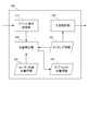
- FIG. 1 is a diagram showing a schematic configuration of a system according to an embodiment of the present invention.
- the system 10 includes an event-driven vision sensor 100, a light source 200, and a position detector 300.
- the vision sensor 100 includes a sensor array in which an asynchronous solid-state image sensor that generates an event signal when a change in intensity of light incident through an optical system (not shown), more specifically, a change in brightness is detected, is arranged. ..
- the asynchronous solid-state image sensor included in the vision sensor 100 includes an address event representation (AER: Address Event Representation) circuit.
- the address event means that the amount of light of a pixel fluctuates at a certain pixel address, and the amount of fluctuation exceeds the threshold value.
- the address event includes an on-event indicating that the light intensity of the pixel fluctuates and exceeds a predetermined upper limit value, and an off-event indicating that the light intensity of the pixel fluctuates and falls below a predetermined lower limit value.
- the event signal output from the vision sensor 100 includes a pixel address, a flag (on-event or off-event) indicating the type of address event, and a time stamp.
- the pixel address included in the event signal indicates the two-dimensional position pos in the field of view of the vision sensor 100 of the change in the intensity of light generated in the space to which the vision sensor 100 is directed.
- the time stamp indicates the time when the change in light intensity occurs.
- the light source 200 irradiates directional light toward the same space where the vision sensor 100 is directed.
- the directional light is, for example, an infrared laser.
- the light source 200 scans the space by irradiating directional light linearly and changing the irradiation angle in a time-series pattern in a direction intersecting the line.
- the light source 200 changes the irradiation angle at each time that is synchronized with or can be matched with the time stamp of the event signal output by the vision sensor 100.
- the irradiation angle at each time is instructed in advance by the position detection device 300 to the light source 200, or is transmitted from the light source 200 to the position detection device 300.
- FIG. 2 is a block diagram showing a functional configuration of the position detection device shown in FIG.
- the position detector 300 is implemented by, for example, a computer having a communication interface, a processor, and a memory, and the processor operates according to a program stored in the memory or received through the communication interface. It includes the functional parts of the event signal receiving unit 310, the light source control unit 320, and the position detecting unit 330 to be realized.
- the position detection device 300 may be incorporated in the same device as the vision sensor 100 and the light source 200, or may be arranged in the same space as the vision sensor 100 and the light source 200, respectively, with the vision sensor 100 and the light source 200, respectively. It may be a terminal device that communicates, or it may be a server device that is connected to the vision sensor 100 and the light source 200 via a network. Further, a part of the functions of the position detection device 300 may be implemented in the terminal device, and other functions may be implemented in the server device.
- the event signal receiving unit 310 receives the event signal from the vision sensor 100.
- the event signal is information indicating the two-dimensional position in the field of view of the vision sensor 100 for the change in light intensity generated in space and the time when the change in light intensity occurs.
- the light source control unit 320 controls the light source 200 according to the timing information 340 indicating the light irradiation angle at each time. Alternatively, when the light source 200 transmits the irradiation angle of light at each time to the position detection device 300, the light source control unit 320 may not be provided.
- the position detection unit 330 is based on the event signal received by the event signal reception unit 310, the timing information 340 indicating the light irradiation angle at each time of the light source 200, and the position information 350 of the vision sensor 100 and the light source 200. Detects the three-dimensional position of the change in light intensity generated in space. In the present embodiment, the position detection unit 330 outputs the detected three-dimensional position of the light intensity change as the object position information 360.
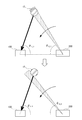
- the position detection unit 330 detects the position of an object existing in the space in the present embodiment.
- the light emitted by the light source 200 is reflected by the object obj existing in the space, the intensity of the light is changed by the reflected light, and the vision sensor 100 detects the event.
- the angle ⁇ 1 of the object obj with reference to the vision sensor 100 can be specified.
- the irradiation angle ⁇ 2 of the light by the light source 200 at each time is known. If the positional relationship between the vision sensor 100 and the light source 200 (shown as the distance L) is added to this, the three-dimensional position of the object obj can be specified by the principle of triangulation.
- the light source 200 linearly irradiates directional light. Therefore, when an event due to the reflected light at the object obj is detected at a certain time, the object obj is specified to be on a plane formed by the linear light irradiated at that time.
- the angle ⁇ 1 specified from the two-dimensional position pos of the event in the field of view of the vision sensor 100 is a three-dimensional angle, it is specified by the plane and angle ⁇ 1 formed by the above light in the three-dimensional space. The point where the straight line intersects can be detected as the three-dimensional position of the object obj.
- the irradiation angle at which the light source 200 linearly irradiates directional light is, for example, a time series including changes in the irradiation angles in two directions intersecting each other.
- two planes including the object obj are specified from the time when the event occurred in each irradiation, and the angle ⁇ 2 is specified as a three-dimensional angle as the angle of intersection of these planes. be able to.
- the three-dimensional position of the object obj is detected as the intersection of two straight lines specified by the angles ⁇ 1 and ⁇ 2 .
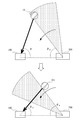
- the light source 200 may irradiate directional light in a wide linear shape.
- the event due to the reflected light on the object obj occurs twice with a time lag (on event and off event).
- the light source 200 may irradiate directional light in a wider band, as shown in FIG.
- the light source 200 scans the space by changing the irradiation angle in the width direction of the band in a time-series pattern.
- the event due to the reflected light on the object obj occurs twice with a time lag (on event and off event).
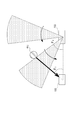
- the time difference is larger than that of the example of FIG. 3, for example, when the object obj is moving, the position of the object obj differs between the on-event and the off-event.
- the second three-dimensional position detected based on the angle ⁇ 4 of the trailing edge is treated as indicating the three-dimensional position of the object obj at different times. That is, the first three-dimensional position and the second three-dimensional position are treated as time-series changes in the three-dimensional position. For example, as shown in FIG. 5, when the light source 200 irradiates directional light in a plurality of bands, the front edge and the trailing edge of the light are arranged at equal intervals, and the on-event and the off-event occur at intervals. By equalizing, the three-dimensional position of the object obj can be detected by scanning the space at an arbitrary cycle.
- FIG. 6 is a flowchart showing an example of processing in one embodiment of the present invention.
- the position detection unit 330 emits light intensity.
- the position where the change occurs is detected as the position of the object in the space (step S103).
- the position of an object in space can be detected quickly and accurately.
- Event-driven vision sensors operate at high speeds by generating event signals asynchronously in time, reducing the time or cycle required for object position detection within the time resolution of controlling the angle of light emitted by a light source. can do.
- it is possible to detect the position of an object by detecting the reflection of the irradiated light from the image captured by the frame type vision sensor, but the frame type vision sensor uses time-synchronous scanning. Since the image is captured, the speed is slower than that of the event-driven vision sensor, and the time or period required for detecting the position of the object is longer.
- the position where the light intensity change occurs is directly specified, so that the position can be detected more accurately than when performing image processing for extracting a reflected image from an image, for example. it can.
- a game controller for example, a game controller, a smartphone, and various moving objects (automobiles, electric vehicles, hybrid electric vehicles, motorcycles, bicycles, personal mobility, airplanes, drones, ships, robots, etc.) are used to provide information on the surrounding environment. It can be used to acquire, estimate its own position from the positions of surrounding objects, detect incoming objects, and take evasive action.
- moving objects autonomouss, electric vehicles, hybrid electric vehicles, motorcycles, bicycles, personal mobility, airplanes, drones, ships, robots, etc.
- 10 ... system, 100 ... vision sensor, 200 ... light source, 300 ... position detection device, 310 ... event signal receiver, 320 ... light source control unit, 330 ... position detection unit.
Landscapes
- Engineering & Computer Science (AREA)
- Multimedia (AREA)
- Signal Processing (AREA)
- Physics & Mathematics (AREA)
- General Physics & Mathematics (AREA)
- Length Measuring Devices By Optical Means (AREA)
- Measurement Of Optical Distance (AREA)
- Transforming Light Signals Into Electric Signals (AREA)
- Electromagnetism (AREA)
- Radar, Positioning & Navigation (AREA)
- Remote Sensing (AREA)
Priority Applications (3)
| Application Number | Priority Date | Filing Date | Title |
|---|---|---|---|
| JP2021528690A JP7311597B2 (ja) | 2019-06-25 | 2019-06-25 | システム、位置検出装置、位置検出方法およびプログラム |
| PCT/JP2019/025112 WO2020261370A1 (ja) | 2019-06-25 | 2019-06-25 | システム、位置検出装置、位置検出方法およびプログラム |
| US17/595,790 US20220311923A1 (en) | 2019-06-25 | 2019-06-25 | System, position detecting device, position detecting method, and program |
Applications Claiming Priority (1)
| Application Number | Priority Date | Filing Date | Title |
|---|---|---|---|
| PCT/JP2019/025112 WO2020261370A1 (ja) | 2019-06-25 | 2019-06-25 | システム、位置検出装置、位置検出方法およびプログラム |
Publications (1)
| Publication Number | Publication Date |
|---|---|
| WO2020261370A1 true WO2020261370A1 (ja) | 2020-12-30 |
Family
ID=74059682
Family Applications (1)
| Application Number | Title | Priority Date | Filing Date |
|---|---|---|---|
| PCT/JP2019/025112 Ceased WO2020261370A1 (ja) | 2019-06-25 | 2019-06-25 | システム、位置検出装置、位置検出方法およびプログラム |
Country Status (3)
| Country | Link |
|---|---|
| US (1) | US20220311923A1 (https=) |
| JP (1) | JP7311597B2 (https=) |
| WO (1) | WO2020261370A1 (https=) |
Cited By (1)
| Publication number | Priority date | Publication date | Assignee | Title |
|---|---|---|---|---|
| JP2023105510A (ja) * | 2022-01-19 | 2023-07-31 | 日本電信電話株式会社 | 三次元計測装置、三次元計測方法及びプログラム |
Citations (3)
| Publication number | Priority date | Publication date | Assignee | Title |
|---|---|---|---|---|
| US20140085621A1 (en) * | 2012-09-26 | 2014-03-27 | Samsung Electronics Co., Ltd. | Proximity sensor and proximity sensing method using event-based vision sensor |
| US20170366801A1 (en) * | 2016-06-20 | 2017-12-21 | Intel Corporation | Depth image provision apparatus and method |
| EP3477341A1 (en) * | 2017-10-31 | 2019-05-01 | Thomson Licensing | Method for obtaining information about description of an object in a 3d real environment, corresponding computer program product, carrier medium and device |
Family Cites Families (5)
| Publication number | Priority date | Publication date | Assignee | Title |
|---|---|---|---|---|
| US8930063B2 (en) * | 2012-02-22 | 2015-01-06 | GM Global Technology Operations LLC | Method for determining object sensor misalignment |
| CN109997057B (zh) * | 2016-09-20 | 2020-07-14 | 创新科技有限公司 | 激光雷达系统和方法 |
| WO2019064062A1 (en) * | 2017-09-26 | 2019-04-04 | Innoviz Technologies Ltd. | SYSTEMS AND METHODS FOR DETECTION AND LOCATION BY LIGHT |
| US10516876B2 (en) * | 2017-12-19 | 2019-12-24 | Intel Corporation | Dynamic vision sensor and projector for depth imaging |
| KR102233260B1 (ko) * | 2018-10-02 | 2021-03-29 | 에스케이텔레콤 주식회사 | 정밀 지도 업데이트 장치 및 방법 |
-
2019
- 2019-06-25 WO PCT/JP2019/025112 patent/WO2020261370A1/ja not_active Ceased
- 2019-06-25 JP JP2021528690A patent/JP7311597B2/ja active Active
- 2019-06-25 US US17/595,790 patent/US20220311923A1/en active Pending
Patent Citations (3)
| Publication number | Priority date | Publication date | Assignee | Title |
|---|---|---|---|---|
| US20140085621A1 (en) * | 2012-09-26 | 2014-03-27 | Samsung Electronics Co., Ltd. | Proximity sensor and proximity sensing method using event-based vision sensor |
| US20170366801A1 (en) * | 2016-06-20 | 2017-12-21 | Intel Corporation | Depth image provision apparatus and method |
| EP3477341A1 (en) * | 2017-10-31 | 2019-05-01 | Thomson Licensing | Method for obtaining information about description of an object in a 3d real environment, corresponding computer program product, carrier medium and device |
Cited By (2)
| Publication number | Priority date | Publication date | Assignee | Title |
|---|---|---|---|---|
| JP2023105510A (ja) * | 2022-01-19 | 2023-07-31 | 日本電信電話株式会社 | 三次元計測装置、三次元計測方法及びプログラム |
| JP7705046B2 (ja) | 2022-01-19 | 2025-07-09 | 日本電信電話株式会社 | 三次元計測装置、三次元計測方法及びプログラム |
Also Published As
| Publication number | Publication date |
|---|---|
| JP7311597B2 (ja) | 2023-07-19 |
| US20220311923A1 (en) | 2022-09-29 |
| JPWO2020261370A1 (https=) | 2020-12-30 |
Similar Documents
| Publication | Publication Date | Title |
|---|---|---|
| JP7448246B2 (ja) | 深度感知コンピュータビジョンシステム | |
| JP5470886B2 (ja) | 物体検出装置 | |
| JP5316572B2 (ja) | 物体認識装置 | |
| TWI624170B (zh) | 影像掃描系統及其方法 | |
| WO2020261491A1 (ja) | センサ制御装置、センサ制御方法およびプログラム | |
| JP2009174900A (ja) | 物体検出装置、物体検出方法および物体検出システム | |
| WO2020261408A1 (ja) | システム、情報処理装置、情報処理方法およびプログラム | |
| JP6772639B2 (ja) | 視差演算システム、移動体及びプログラム | |
| WO2020255399A1 (ja) | 位置検出システム、画像処理装置、位置検出方法および位置検出プログラム | |
| JP2010127835A (ja) | レーダ装置 | |
| WO2019146510A1 (ja) | 画像処理装置 | |
| WO2014108976A1 (ja) | 物体検出装置 | |
| JP2014137762A (ja) | 物体検出装置 | |
| JPWO2020049892A1 (ja) | 車載レーダシステム | |
| JP2024109967A (ja) | 認識処理システム、認識処理装置及び認識処理方法 | |
| WO2020261370A1 (ja) | システム、位置検出装置、位置検出方法およびプログラム | |
| JP6260418B2 (ja) | 距離測定装置、距離測定方法および距離測定プログラム | |
| WO2023188183A1 (ja) | 情報処理装置、システム、情報処理方法、情報処理プログラム、およびコンピュータシステム | |
| JP2010071942A (ja) | 物体検出装置 | |
| JP4849013B2 (ja) | 車両周辺監視装置 | |
| JP6379646B2 (ja) | 情報処理装置、測定方法及びプログラム | |
| KR20220163939A (ko) | 터치식 이미지 센서 | |
| US20250209650A1 (en) | Information processing apparatus, system, information processing method, information processing program, and computer system | |
| JP2013246009A (ja) | 物体検出装置 | |
| JP2014021017A (ja) | 情報取得装置および物体検出装置 |
Legal Events
| Date | Code | Title | Description |
|---|---|---|---|
| 121 | Ep: the epo has been informed by wipo that ep was designated in this application |
Ref document number: 19935353 Country of ref document: EP Kind code of ref document: A1 |
|
| ENP | Entry into the national phase |
Ref document number: 2021528690 Country of ref document: JP Kind code of ref document: A |
|
| NENP | Non-entry into the national phase |
Ref country code: DE |
|
| 122 | Ep: pct application non-entry in european phase |
Ref document number: 19935353 Country of ref document: EP Kind code of ref document: A1 |