WO2020255673A1 - 情報処理装置、情報処理方法、およびプログラム - Google Patents
情報処理装置、情報処理方法、およびプログラム Download PDFInfo
- Publication number
- WO2020255673A1 WO2020255673A1 PCT/JP2020/021249 JP2020021249W WO2020255673A1 WO 2020255673 A1 WO2020255673 A1 WO 2020255673A1 JP 2020021249 W JP2020021249 W JP 2020021249W WO 2020255673 A1 WO2020255673 A1 WO 2020255673A1
- Authority
- WO
- WIPO (PCT)
- Prior art keywords
- screen
- information processing
- menu screen
- electronic device
- configuration information
- Prior art date
- Legal status (The legal status is an assumption and is not a legal conclusion. Google has not performed a legal analysis and makes no representation as to the accuracy of the status listed.)
- Ceased
Links
Images







Classifications
-
- G—PHYSICS
- G06—COMPUTING OR CALCULATING; COUNTING
- G06F—ELECTRIC DIGITAL DATA PROCESSING
- G06F3/00—Input arrangements for transferring data to be processed into a form capable of being handled by the computer; Output arrangements for transferring data from processing unit to output unit, e.g. interface arrangements
- G06F3/01—Input arrangements or combined input and output arrangements for interaction between user and computer
- G06F3/048—Interaction techniques based on graphical user interfaces [GUI]
- G06F3/0481—Interaction techniques based on graphical user interfaces [GUI] based on specific properties of the displayed interaction object or a metaphor-based environment, e.g. interaction with desktop elements like windows or icons, or assisted by a cursor's changing behaviour or appearance
- G06F3/0482—Interaction with lists of selectable items, e.g. menus
-
- G—PHYSICS
- G06—COMPUTING OR CALCULATING; COUNTING
- G06F—ELECTRIC DIGITAL DATA PROCESSING
- G06F3/00—Input arrangements for transferring data to be processed into a form capable of being handled by the computer; Output arrangements for transferring data from processing unit to output unit, e.g. interface arrangements
- G06F3/01—Input arrangements or combined input and output arrangements for interaction between user and computer
- G06F3/048—Interaction techniques based on graphical user interfaces [GUI]
- G06F3/0484—Interaction techniques based on graphical user interfaces [GUI] for the control of specific functions or operations, e.g. selecting or manipulating an object, an image or a displayed text element, setting a parameter value or selecting a range
- G06F3/04847—Interaction techniques to control parameter settings, e.g. interaction with sliders or dials
-
- G—PHYSICS
- G06—COMPUTING OR CALCULATING; COUNTING
- G06F—ELECTRIC DIGITAL DATA PROCESSING
- G06F3/00—Input arrangements for transferring data to be processed into a form capable of being handled by the computer; Output arrangements for transferring data from processing unit to output unit, e.g. interface arrangements
- G06F3/01—Input arrangements or combined input and output arrangements for interaction between user and computer
- G06F3/048—Interaction techniques based on graphical user interfaces [GUI]
- G06F3/0484—Interaction techniques based on graphical user interfaces [GUI] for the control of specific functions or operations, e.g. selecting or manipulating an object, an image or a displayed text element, setting a parameter value or selecting a range
- G06F3/0486—Drag-and-drop
-
- H—ELECTRICITY
- H04—ELECTRIC COMMUNICATION TECHNIQUE
- H04M—TELEPHONIC COMMUNICATION
- H04M1/00—Substation equipment, e.g. for use by subscribers
- H04M1/72—Mobile telephones; Cordless telephones, i.e. devices for establishing wireless links to base stations without route selection
- H04M1/724—User interfaces specially adapted for cordless or mobile telephones
- H04M1/72403—User interfaces specially adapted for cordless or mobile telephones with means for local support of applications that increase the functionality
- H04M1/72409—User interfaces specially adapted for cordless or mobile telephones with means for local support of applications that increase the functionality by interfacing with external accessories
-
- H—ELECTRICITY
- H04—ELECTRIC COMMUNICATION TECHNIQUE
- H04M—TELEPHONIC COMMUNICATION
- H04M1/00—Substation equipment, e.g. for use by subscribers
- H04M1/72—Mobile telephones; Cordless telephones, i.e. devices for establishing wireless links to base stations without route selection
- H04M1/724—User interfaces specially adapted for cordless or mobile telephones
- H04M1/72403—User interfaces specially adapted for cordless or mobile telephones with means for local support of applications that increase the functionality
- H04M1/72406—User interfaces specially adapted for cordless or mobile telephones with means for local support of applications that increase the functionality by software upgrading or downloading
-
- H—ELECTRICITY
- H04—ELECTRIC COMMUNICATION TECHNIQUE
- H04M—TELEPHONIC COMMUNICATION
- H04M1/00—Substation equipment, e.g. for use by subscribers
- H04M1/72—Mobile telephones; Cordless telephones, i.e. devices for establishing wireless links to base stations without route selection
- H04M1/724—User interfaces specially adapted for cordless or mobile telephones
- H04M1/72448—User interfaces specially adapted for cordless or mobile telephones with means for adapting the functionality of the device according to specific conditions
Definitions
- This disclosure relates to information processing devices, information processing methods, and programs.
- a GUI Graphic User Interface
- buttons and text boxes displayed on a computer screen so that a user can easily operate them in order to make various settings for an electronic device.
- Patent Document 1 discloses a technique of an application program having a function of saving a customized toolbar configuration in a file and a function of reading the configuration saved in the file and reconstructing the toolbar.
- An object of the present disclosure is to provide an information processing device, an information processing method, and a program capable of easily configuring an appropriate customized screen.
- the information processing apparatus of the present disclosure acquires a menu screen configuration information including a predetermined setting item stored in the electronic device when the electronic device is connected, and the acquired menu screen configuration information.
- the electronic device stores the generation unit that changes based on the setting items selected according to the electronic device connected from the plurality of selectable setting items, and the menu screen configuration information changed in the generation unit. It includes a memory control unit.
- a step of acquiring menu screen configuration information including a predetermined setting item stored in the electronic device and the acquired menu screen configuration information are obtained. It includes a step of changing based on a setting item selected according to a connected electronic device from a plurality of selectable setting items, and a step of storing the changed menu screen configuration information in the electronic device.
- a step of acquiring menu screen configuration information including a predetermined setting item stored in the electronic device and the acquired menu screen configuration information can be selected.
- the computer execute a step of changing based on the setting item selected according to the connected electronic device from a plurality of setting items and a step of storing the changed menu screen configuration information in the electronic device. ..
- an appropriate customization screen can be easily configured.
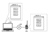
- FIG. 1 is a diagram showing a configuration of an information processing system according to an embodiment of the present disclosure.
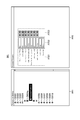
- FIG. 2 is a diagram for explaining a general method of setting setting items in the radio.
- FIG. 3 is a block diagram showing an example of the configuration of the information processing apparatus according to the embodiment of the present disclosure.
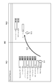
- FIG. 4 is a diagram for explaining a method of generating a customized screen.
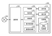
- FIG. 5 is a block diagram showing an example of the configuration of the radio device according to the embodiment of the present disclosure.
- FIG. 6 is a diagram for explaining a method of generating a customized screen according to the embodiment of the present disclosure.
- FIG. 7 is a diagram for explaining a method of reading out the customization screen saved for each radio.
- FIG. 1 is a diagram showing a configuration of an information processing system according to an embodiment of the present disclosure.
- FIG. 2 is a diagram for explaining a general method of setting setting items in the radio.
- FIG. 3 is a block diagram showing an example of the configuration of the information processing
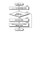
- FIG. 8 is a flowchart showing an example of a processing flow of the control unit of the information processing apparatus according to the first embodiment of the present disclosure.
- FIG. 9 is a diagram for explaining the processing of the information processing system according to the second embodiment of the present disclosure.
- FIG. 10A is a diagram for explaining a method of adding a setting item to the customization screen.
- FIG. 10B is a diagram for explaining a method of adding a setting item to the customization screen.
- FIG. 10C is a diagram for explaining a method of adding a setting item to the customization screen.
- FIG. 11 is a flowchart showing an example of a flow of processing in which the control unit of the information processing apparatus adds a setting item to the customization screen.
- FIG. 10A is a diagram for explaining a method of adding a setting item to the customization screen.
- FIG. 10B is a diagram for explaining a method of adding a setting item to the customization screen.
- FIG. 10C is a diagram for explaining a method of adding a
- FIG. 12A is a diagram for explaining a method of deleting a setting item from the customization screen.
- FIG. 12B is a diagram for explaining a method of deleting a setting item from the customization screen.
- FIG. 12C is a diagram for explaining a method of deleting a setting item from the customization screen.
- FIG. 13 is a flowchart showing an example of a flow of processing in which the control unit of the information processing apparatus deletes a setting item from the customization screen.
- FIG. 1 is a diagram showing a configuration of an information processing system according to an embodiment of the present disclosure.
- the information processing system 1 includes an information processing device 100 and a radio 200.
- the information processing device 100 and the wireless device 200 are connected to each other via a wired or wireless network NW.
- the information processing device 100 generates a customized screen composed of only necessary setting items from various setting items of the radio 200 in a state of being connected to the radio 200.
- the information processing device 100 customizes the setting items for the radio device 200 as an example, but the present disclosure is not limited to this.
- the present disclosure can also be applied when customizing setting items for various electronic devices.
- FIG. 2 is a diagram for explaining a general method of setting setting items in the radio 200.
- the display screen IM1 is an example of a screen displayed on the information processing device 100 when the user sets a setting item on the radio 200.
- the display screen IM1 includes the area AR1 and the area AR2.
- Various setting items for the radio 200 are displayed in the area AR1.
- "SI001" to “SI010” are shown as setting items. Although it is conceptually shown as “SI001" in FIG. 2, the name of a specific setting item such as a network name is actually described.
- the setting items displayed in the area AR1 are displayed hierarchically in, for example, a tree display. Specifically, for example, the setting item “SI004a” exists in the hierarchy below the setting item "SI004". For example, "Personal Features” exists in the hierarchy below the setting item "SI004a".
- the area AR2 shows an example in which “Personal Features” is selected in the area AR1.
- Region AR2 includes region AR21, region AR22, region AR23, and AR24.
- the set value of the setting item is displayed in the area AR22.
- “Time-out Timer (TOT) [s]” is "60 seconds”.
- a button for changing the setting value of the setting item is displayed.
- the user can raise the installation value by pressing the up arrow button and lower the set value by pressing the down arrow button.
- the states of "Transmit Power” and "Battery Saver” can be changed by the buttons displayed in the area AR22.
- the desired setting item is searched for from the area AR1, and the value of the detailed setting item displayed in the area AR2 is further changed.
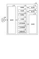
- FIG. 3 is a block diagram showing an example of the configuration of the information processing apparatus according to the embodiment of the present disclosure.
- the information processing device 100 includes an operation unit 110, a display unit 120, a communication unit 130, a storage unit 140, and a control unit 150.
- the operation unit 110 receives various operations from the user.
- the operation unit 110 accepts, for example, an operation for generating a customized screen composed of items to be set for an electronic device.
- the operation unit 110 accepts, for example, an operation for setting or changing the value of a parameter of a setting item.
- the operation unit 110 outputs, for example, an electric signal corresponding to the operation to the control unit 150.
- the operation unit 110 is realized by, for example, a keyboard, a mouse, and a touch panel.
- the display unit 120 displays various types of information.
- the display unit 120 displays, for example, a GUI including various setting items to be set for the electronic device.
- the display unit 120 is a display including, for example, a liquid crystal display (LCD: Liquid Crystal Display) or an organic EL (Organic Electro-Luminescence) display.
- LCD Liquid Crystal Display
- organic EL Organic Electro-Luminescence
- the communication unit 130 is realized by, for example, a NIC (Network Interface Card), a communication circuit, or the like.
- the communication unit 130 is connected to a network NW (Internet or the like) by wire or wirelessly.
- NW Internet or the like
- the communication unit 130 transmits / receives information to / from other devices and the like via the network NW.
- the communication unit 130 transmits / receives information to / from the radio 200, for example.
- the storage unit 140 stores various types of information.
- the storage unit 140 is realized by, for example, a semiconductor memory element such as a RAM (Random Access Memory) or a flash memory (Flash Memory), or a storage device such as a hard disk or an optical disk.
- control unit 150 for example, a program (for example, a program according to the present disclosure) stored in a storage unit (not shown) by a CPU (Central Processing Unit), an MPU (Micro Processing Unit), or the like stores a RAM (Random Access Memory) or the like. It is realized by being executed as a work area. Further, the control unit 150 is a controller, and may be realized by an integrated circuit such as an ASIC (Application Specific Integrated Circuit) or an FPGA (Field Programmable Gate Array).
- the control unit 150 includes a determination unit 151, an acquisition unit 152, a generation unit 153, a display control unit 154, a memory control unit 155, and a communication control unit 156.
- the determination unit 151 determines various types of information. The determination unit 151 determines, for example, whether or not an electronic device is connected to the information processing device 100. The determination unit 151 determines, for example, whether or not the information processing device 100 and the radio device 200 are connected.
- the acquisition unit 152 acquires various types of information.
- the acquisition unit 152 acquires various types of information from, for example, an electronic device connected to the information processing device 100.
- the acquisition unit 152 acquires, for example, menu screen configuration information related to a customization screen including only setting items set in the electronic device from the electronic device connected to the information processing device 100.
- Generation unit 153 generates various types of information. For example, the generation unit 153 generates a customization screen including only the setting items corresponding to the radio 200 according to the electric signal corresponding to the operation received from the operation unit 110. The generation unit 153 generates, for example, menu screen configuration information related to the generated customization screen. The generation unit 153 updates, for example, the parameters of the setting items included in the generated customization screen.
- FIG. 4 is a diagram for explaining a method of generating a customized screen.
- the display screen IM2 is a screen displayed on the display unit 120 when a customized screen is generated.
- the display screen IM2 includes a setting screen IM21 and a customization screen IM22.
- the setting screen IM21 and the customization screen IM22 are displayed adjacent to each other, for example.
- the generation unit 153 selects "Transmit Power” on which the cursor is placed according to the operation of the operation unit 110 (step S11).
- the generation unit 153 accepts an operation by the operation unit 110 to move the user to the customization screen IM22 while dragging "Transmit Power” (step S12).
- the generation unit 153 generates "Transmit Power” on the customization screen IM22 (step S13).
- various settings for the radio 200 can be facilitated.
- the display control unit 154 causes the display unit 120 to display various types of information.
- the display control unit 154 causes the display unit 120 to display the display screen IM2 shown in FIG. 4, for example.
- the storage control unit 155 stores various information in the storage unit 140.
- the storage control unit 155 stores various information in the radio 200.
- the storage control unit 155 stores, for example, the menu screen configuration information related to the customized screen IM22 illustrated in FIG. 4 in the radio 200.
- the communication control unit 156 controls various communications via the communication unit 130.
- the communication control unit 156 controls communication with, for example, the radio 200 and the like.
- FIG. 5 is a block diagram showing an example of the configuration of the radio 200 according to the embodiment of the present disclosure.
- the radio 200 includes an operation unit 210, a display unit 220, a communication unit 230, a storage unit 240, and a control unit 250.
- a microphone, a speaker, a wireless transmitter / receiver, and an antenna are also provided as wireless devices, but they are omitted here.
- the operation unit 210 receives various operations from the user.
- the operation unit 110 outputs, for example, an electric signal corresponding to the operation to the control unit 250.
- the operation unit 110 is realized by, for example, a physical button or a touch panel.
- the display unit 220 displays various types of information.
- the display unit 220 displays various information related to communication such as radio wave strength.
- the display unit 220 is a display including, for example, a liquid crystal display or an organic EL display.
- the operation unit 210 is composed of a touch panel, the display unit 220 is provided integrally with the operation unit 210.
- the communication unit 230 is realized by, for example, a NIC or a communication circuit.
- the communication unit 230 is connected to the network NW by wire or wirelessly.
- the communication unit 230 transmits / receives information to / from other devices and the like via the network NW.
- the communication unit 230 transmits / receives information to / from the information processing device 100, for example.
- the storage unit 240 stores various types of information.
- the storage unit 240 is realized by, for example, a semiconductor memory element such as a RAM or a flash memory, or a storage device such as a hard disk or an optical disk.
- the storage unit 240 has a configuration file storage unit 241.
- the configuration file storage unit 241 stores menu screen configuration information for configuring a customization screen including only the setting items set in the radio 200.
- the control unit 250 is realized by, for example, a CPU, an MPU, or the like executing a program stored in a storage unit (not shown) with a RAM or the like as a work area. Further, the control unit 250 is a controller, and may be realized by an integrated circuit such as an ASIC or FPGA.
- the control unit 250 includes an acquisition unit 251, a search unit 252, a display control unit 253, and a communication control unit 254.
- the acquisition unit 251 acquires various types of information.
- the acquisition unit 251 acquires various types of information from, for example, an electronic device connected to the radio 200.
- the acquisition unit 251 acquires various types of information from, for example, the storage unit 240.
- the acquisition unit 251 acquires the menu screen configuration information, for example, when the configuration file storage unit 241 stores the menu screen configuration information.
- the search unit 252 searches for various types of information.
- the search unit 252 searches, for example, various types of information stored in the storage unit 240.
- the search unit 252 for example, searches the menu screen configuration information from the configuration file storage unit 241 to determine whether or not the configuration file storage unit 241 stores the menu screen configuration information.
- the search unit 252 transmits, for example, the search result of the menu screen configuration information to the information processing device 100.
- the display control unit 253 causes the display unit 220 to display various types of information.
- the display control unit 253 displays, for example, various information related to communication on the display unit 220.
- the communication control unit 254 controls various communications via the communication unit 230.
- the communication control unit 254 controls communication with, for example, the information processing device 100 and the like.
- FIG. 6 is a diagram for explaining a method of generating a customized screen according to the embodiment of the present disclosure.
- the information processing device 100 and the wireless device 200 will be described as being in a state of being communicably connected to each other via a wired or wireless network NW.
- the GUI screen IM3 includes a default screen IM31 and a customized screen IM32.
- the default screen IM31 includes all setting items for the radio 200.
- the default screen IM31 will be described as including four buttons, a button A, a button B, a button C, and a button D. Functions corresponding to various setting items as shown in FIG. 4 are assigned to the buttons A to D.
- the customization screen IM32 includes only the setting items selected by the user according to the radio 200.
- the user can arrange the buttons on the customization screen IM32 by dragging and dropping the necessary buttons from the default screen IM31 to the customization screen IM32 using, for example, the operation unit 110 composed of a mouse or the like.
- the user drags and drops the button A from the default screen IM31 to the customization screen IM32 (step S21), for example.
- the generation unit 153 generates the button A on the customization screen IM32.
- the user drags and drops the button B from the default screen IM31 to the customization screen IM32 (step S22).
- the generation unit 153 generates the button B on the customization screen IM32.
- the user drags and drops the button D from the default screen IM31 to the customization screen IM32 (step S23).
- the generation unit 153 generates the button D on the customization screen IM32.
- three buttons, a button A, a button B, and a button D, are arranged on the customization screen IM32.
- the generation unit 153 may change the parameter values of the setting items corresponding to the button A, the button B, and the button D according to the radio 200. That is, the generation unit 153 can generate a customization screen according to the radio 200 not only for the setting items but also for the parameter values of the setting items.
- the information processing device 100 can store the menu screen configuration information regarding the customized screen IM32 in which the three buttons of the button A, the button B, and the button D are arranged in the storage unit 240 of the radio 200.
- the storage control unit 155 stores the menu screen configuration information in the configuration file storage unit 241 of the storage unit 240.
- the menu screen configuration information includes various information such as the type of button and the coordinates of the place to be displayed on the screen. Therefore, the information processing device 100 can automatically display the customized screen corresponding to the radio 200 by acquiring the menu screen configuration information from the configuration file storage unit 241.
- FIG. 7 is a diagram for explaining a method of reading out the customization screen saved for each radio device 200.
- FIG. 7 includes an information processing device 100A, an information processing device 100B, a radio device 200A, and a radio device 200B.
- the information processing device 100A and the information processing device 100B have the same configuration as the information processing device 100 shown in FIG.
- the radio 200A and the radio 200B have the same configuration as the radio 200 shown in FIG.
- the radio 200A stores the menu screen configuration information regarding the customized screen IM32-1 in which the button A, the button B, and the button D are arranged in the configuration file storage unit 241 of the storage unit 240.
- the radio 200B stores the menu screen configuration information regarding the customized screen IM32-2 in which the button A and the button B are arranged in the configuration file storage unit 241 of the storage unit 240.
- the acquisition unit 152 acquires the menu screen configuration information related to the customization screen IM32-1 from the radio 200A.
- the display control unit 154 displays the customization screen IM32-1 on the display unit 120.
- the acquisition unit 152 acquires the menu screen configuration information related to the customization screen IM32-2 from the radio 200B. .. In this case, the display control unit 154 displays the customization screen IM32-2 on the display unit 120.
- the information processing device 100B can execute the same processing as the information processing device 100A.
- the information processing device 100A and the information processing device 100B are the radio device 200A and the radio device 200B by storing the menu screen configuration information in the radio device 200A and the radio device 200B, respectively.
- the customization screen can be displayed.
- the present disclosure is set in the radio device regardless of the information processing device connected to the information processing device and the radio device connected to the information processing device by storing the menu screen configuration information on the radio device side.
- the customization screen can be displayed.
- FIG. 8 is a flowchart showing an example of a processing flow of the control unit of the information processing apparatus according to the first embodiment of the present disclosure.
- the control unit 150 determines whether or not a radio is connected to the information processing device 100 (step S101). Specifically, the determination unit 151 determines whether or not the radio device 200 is connected to the information processing device 100 via a wired or wireless network NW. When it is determined that the radio 200 is not connected (No in step S101), the control unit 150 repeats the process of step S101. If it is determined that the radio 200 is connected (Yes in step S101), the process proceeds to step S102.
- step S101 the control unit 150 requests the radio device 200 for menu screen configuration information (step S102). Specifically, the acquisition unit 152 requests the radio 200 for menu screen configuration information. Then, the process proceeds to step S103.
- the control unit 150 determines whether or not the menu screen configuration information is stored in the radio 200 (step S103). Specifically, the communication control unit 156 determines whether or not the menu screen configuration information is stored in the radio 200 based on the search result of the menu screen configuration information received from the radio 200. If it is determined that the menu screen configuration information is stored (Yes in step S103), the process proceeds to step S104. If it is determined that the menu screen configuration information is not stored (No in step S103), the process proceeds to step S106.
- step S104 the control unit 150 acquires the menu screen configuration information from the radio 200 (step S104). Specifically, the acquisition unit 152 acquires the menu screen configuration information stored in the configuration file storage unit 241. Then, the process proceeds to step S105.
- the control unit 150 displays the customization screen of the radio 200 (step S105). Specifically, the display control unit 154 displays the customized screen on the display unit 120 based on the menu screen configuration information acquired by the acquisition unit 152. Then, the process of FIG. 8 ends.
- control unit 150 displays the default screen (step S106). Specifically, the display control unit 154 displays the default screen on the display unit 120.
- the customization screen including only the items necessary for the wireless device can be displayed, it becomes easier to find the button to change the setting, and the operability is improved.
- FIG. 9 is a diagram for explaining the processing of the information processing system 1 according to the second embodiment of the present disclosure.
- the information processing system 1 changes the setting items included in the customization screen set in the radio 200. Specifically, when the information processing system 1 adds or deletes to the setting items included in the customization screen set in the radio 200, it is previously set as a preset item from a plurality of selectable setting items of the default screen IM31. After displaying the selected setting item on the customization screen IM32A, the menu screen configuration information of the radio 200 is acquired. The case where the setting item to be changed is the button C will be described below.
- the GUI screen IM3A includes a default screen IM31 and a customized screen IM32A.
- the user drags and drops the button C, which is a setting item (also called a change item) to be changed, from the default screen IM31 to the customization screen IM32A (step S31).
- the generation unit 153 generates the button C on the customization screen IM32A.
- FIGS. 10A, 10B, and 10C are diagrams for explaining a method of adding a setting item to the customization screen.
- FIG. 10A shows an information processing device 100 and a radio device 200.
- the information processing device 100 only the button C is displayed on the customization screen IM32A.
- the radio 200 stores the menu screen configuration information related to the customized screen IM32-1 including the button A, the button B, and the button D.
- the information processing device 100 and the radio 200 are connected via the network NW while the customization screen IM32A including the button C is displayed on the information processing device 100. Let me. As a result, the acquisition unit 152 of the information processing device 100 acquires the menu screen configuration information related to the customized screen IM32-1 from the radio 200.
- the generation unit 153 generates the customization screen IM32A-1 based on the menu screen configuration information regarding the customization screen IM32-1 acquired by the acquisition unit 152. Specifically, the generation unit 153 adds a button C to the customization screen IM32-1 to generate the customization screen IM32A-1. In other words, the generation unit 153 updates the customization screen IM32-1. Then, the storage control unit 155 stores the menu screen configuration information regarding the customization screen IM32A-1 in the radio 200.
- the information processing device 100 displays the customization screen IM32A including only the button C.
- the radio device 200B shown in FIG. 7 is connected to the information processing device 100 shown in FIG. 10C
- a button C is added to the customization screen IM32-2.
- the button C can be added to the customization screen as shown in FIGS. 10A to 10C.
- the information processing device 100 may update the value of the parameter by connecting the radio device 200 with the radio device 200 displaying a screen on which the parameter is to be changed.
- the generation unit 153 may change the parameters of the setting items based on the menu screen configuration information regarding the customization screen IM32-1 acquired by the acquisition unit 152.
- FIG. 11 is a flowchart showing an example of a flow of processing in which the control unit of the information processing apparatus adds a setting item to the customization screen.
- control unit 150 acquires the menu screen configuration information related to the customization screen from the radio 200 connected to the information processing device 100 (step S201). Specifically, the acquisition unit 152 acquires the menu screen configuration information from the radio 200. Then, the process proceeds to step S202.
- the control unit 150 determines whether or not the setting item to be added is included in the customization screen (step S202). Specifically, the generation unit 153 determines whether or not the setting item to be added to the customization screen is included. When it is determined that the setting item to be added is included (Yes in step S202), the process of FIG. 11 ends. If it is determined that the setting item to be added is not included (No in step S202), the process proceeds to step S203.
- step S202 the control unit 150 adds a setting item to be added to the customization screen (step S203). Specifically, the setting item that the generation unit 153 wants to add is added to the customization screen and updated. Then, the process proceeds to step S204.
- the control unit 150 stores the menu screen configuration information related to the updated customization screen in the radio 200 (step S204). Specifically, the storage control unit 155 stores in the configuration file storage unit 241 of the storage unit 240 of the radio 200. Then, the process of FIG. 11 is completed.
- FIGS. 12A, 12B, and 12C are diagrams for explaining a method of deleting a setting item from the customization screen.
- FIG. 12A shows the information processing device 100 and the radio device 200.
- the information processing device 100 displays the customization screen IM32A only for the button C.
- the radio 200 stores menu screen configuration information related to the customized screen IM32-3 including the button A, the button B, the button C, and the button D.
- the information processing device 100 and the radio 200 are connected via the network NW while the information processing device 100 displays the customization screen IM32A including the button C. Let me.
- the acquisition unit 152 of the information processing device 100 acquires the menu screen configuration information related to the customized screen IM32-3 from the radio 200.
- the generation unit 153 generates the customization screen IM32A-2 based on the menu screen configuration information regarding the customization screen IM32-3 acquired by the acquisition unit 152. Specifically, the generation unit 153 deletes the button C from the customization screen IM32-3 to generate the customization screen IM32A-2. In other words, the generation unit 153 updates the customization screen IM32-3. Then, the storage control unit 155 stores the menu screen configuration information regarding the customization screen IM32A-2 in the radio 200.
- the information processing device 100 displays the customization screen IM32A including only the button C.
- the button C can be displayed from the customization screen. Can be deleted.
- FIG. 13 is a flowchart showing an example of a process flow in which the control unit of the information processing apparatus deletes a setting item from the customization screen.
- step S301 and step S304 are the same as steps S201 and S204 shown in FIG. 11, respectively, description thereof will be omitted.
- the control unit 150 determines whether or not the setting item to be deleted from the customization screen is included (step S302). Specifically, the generation unit 153 determines whether or not the setting item to be deleted from the customization screen is included. When it is determined that the setting item to be deleted is not included (No in step S302), the process of FIG. 13 ends. If it is determined that the setting item to be deleted is included (Yes in step S302), the process proceeds to step S303.
- step S302 the control unit 150 deletes the setting item to be deleted from the customization screen (step S303). Specifically, the setting item to be deleted by the generation unit 153 is deleted from the customization screen and updated. Then, the process proceeds to step S304.
- the arrangement of the buttons after adding the buttons to the customization screen or deleting the buttons from the customization screen may be determined without particular limitation.
- the buttons on the customization screen may be arranged in a predetermined priority order, or when the buttons are added, they may be arranged in the order in which they are added.
- the user may operate the operation unit 110 to adjust the position of the button arranged on the customization screen. ..
- the process for adding or deleting a button to the customize screen has been described, but the present disclosure is not limited to this.
- the disclosure can also be applied to customize various GUI elements such as text boxes, pull-down menus, checkboxes, and radio buttons.
- the information processing device, information processing method, and program of the present embodiment can be used, for example, in an electronic device having a display screen.
- Information processing system 100 Information processing device 110, 210 Operation unit 120, 220 Display unit 130, 230 Communication unit 140, 240 Storage unit 150, 250 Control unit 151 Judgment unit 152, 251 Acquisition unit 153 Generation unit 154, 253 Display control unit 155 Storage control unit 156,254 Communication control unit 200 Radio 241 Configuration file storage unit 252 Search unit
Landscapes
- Engineering & Computer Science (AREA)
- General Engineering & Computer Science (AREA)
- Theoretical Computer Science (AREA)
- Human Computer Interaction (AREA)
- Physics & Mathematics (AREA)
- General Physics & Mathematics (AREA)
- Computer Networks & Wireless Communication (AREA)
- Signal Processing (AREA)
- User Interface Of Digital Computer (AREA)
Abstract
情報処理装置(100)は、電子機器が接続された際に、電子機器に記憶された所定の設定項目を含むメニュー画面構成情報を取得する取得部(152)と、取得されたメニュー画面構成情報を、選択可能な複数の設定項目から接続された電子機器に応じて選ばれた設定項目に基づいて変更する生成部(153)と、生成部(153)において変更されたメニュー画面構成情報を電子機器に記憶させる記憶制御部(155)と、を備える。
Description
本開示は、情報処理装置、情報処理方法、およびプログラムに関する。
電子機器に対して種々の設定をするために、コンピュータの画面にボタンやテキストボックスなどのオブジェクトを表示してユーザが容易に操作できるようにするGUI(Graphical User Interface)が知られている。
電子機器の使用目的はユーザにより異なることもあるため、ユーザが使い易いように設定項目の構成をカスタマイズする技術が知られている。例えば、特許文献1には、カスタマイズされたツールバーの構成をファイルに保存する機能と、ファイルに保存された構成を読み込み、ツールバーを再構成する機能とを持つアプリケーションプログラムの技術が開示されている。
設定項目の種類は数多く存在する。そのため、ユーザは、カスタマイズ画面を構成するためには多くの設定項目の中から必要なものを探し出して設定する必要があった。また、設定項目を更新する際にも、ユーザは、多くの設定項目の中から必要なものを探し出して設定する必要がある。そのため、手間のかからない容易な方法でカスタマイズ画面を構成する方法が求められている。
本開示は、適切なカスタマイズ画面を容易に構成することのできる情報処理装置、情報処理方法、およびプログラムを提供することを目的とする。
本開示の情報処理装置は、電子機器が接続された際に、前記電子機器に記憶された所定の設定項目を含むメニュー画面構成情報を取得する取得部と、取得された前記メニュー画面構成情報を、選択可能な複数の設定項目から接続された電子機器に応じて選ばれた設定項目に基づいて変更する生成部と、前記生成部において変更された前記メニュー画面構成情報を前記電子機器に記憶させる記憶制御部と、を備える。
本開示の情報処理方法は、電子機器が接続された際に、前記電子機器に記憶された所定の設定項目を含むメニュー画面構成情報を取得するステップと、取得された前記メニュー画面構成情報を、選択可能な複数の設定項目から接続された電子機器に応じて選ばれた設定項目に基づいて変更するステップと、変更された前記メニュー画面構成情報を前記電子機器に記憶させるステップと、含む。
本開示のプログラムは、電子機器が接続された際に、前記電子機器に記憶された所定の設定項目を含むメニュー画面構成情報を取得するステップと、取得された前記メニュー画面構成情報を、選択可能な複数の設定項目から接続された電子機器に応じて選ばれた設定項目に基づいて変更するステップと、変更された前記メニュー画面構成情報を前記電子機器に記憶させるステップと、をコンピュータに実行させる。
本開示によれば、適切なカスタマイズ画面を容易に構成することができる。
以下、添付図面を参照して、本開示に係る実施形態を詳細に説明する。なお、この実施形態により本開示が限定されるものではなく、また、実施形態が複数ある場合には、各実施形態を組み合わせて構成するものも含む。
図1を用いて、本開示の実施形態に係る情報処理システムの構成について説明する。図1は、本開示の実施形態に係る情報処理システムの構成を示す図である。
図1に示すように、情報処理システム1は、情報処理装置100と、無線機200とを含む。情報処理装置100と、無線機200とは、有線又は無線のネットワークNWを介して接続されている。情報処理装置100は、無線機200と接続された状態で、無線機200の各種の設定項目の中から必要な設定項目のみで構成されたカスタマイズ画面を生成する。
以下では、情報処理装置100が無線機200に対する設定項目をカスタマイズする方法を例に説明するが、本開示はこれに限定されない。本開示は、各種の電子機器に対する設定項目をカスタマイズする場合にも適用することができる。
図2を用いて、無線機200に設定項目を設定する一般的な方法について説明する。図2は、無線機200に設定項目を設定する一般的な方法を説明するための図である。
表示画面IM1は、ユーザが無線機200に設定項目を設定する際に、情報処理装置100に表示される画面の一例である。表示画面IM1は、領域AR1と、領域AR2とを含む。
領域AR1には、無線機200に対する種々の設定項目が表示される。領域AR1には、設定項目として「SI001」~「SI010」とが示されている。図2では、「SI001」と概念的に示されているが、実際にはネットワーク名等の具体的な設定項目の名称が記載される。領域AR1に表示される設定項目は、例えば、ツリー表示で階層的に表示される。具体的には、設定項目「SI004」の下の階層には、例えば、設定項目「SI004a」が存在する。設定項目「SI004a」の下の階層には、例えば、「Personal Features」が存在する。
領域AR2には、領域AR1で選択された設定項目の詳細が表示される。図2では、領域AR2には、領域AR1で「Personal Features」が選択された例を示している。領域AR2は、領域AR21と、領域AR22と、領域AR23と、AR24とを含む。
領域AR21には、領域AR1で選択された設定項目の詳細な設定項目の名称が表示される。図2では、「Time-out Timer(TOT)[s]」、「TOT Pre-alert[s]」、「Late Entry Cancel Time[s]」、「Traffic Time(Emergency)[s]」、「Traffic Time(Non-Emergency)[s]」、「Traffic Time(Line)[s]」、「Traffic Time(Packet)[s]」、「Transmit Power」、および「Battery Saver」が示されている。
領域AR22には、設定項目の設定値が表示される。例えば、「Time-out Timer(TOT)[s]」は、「60秒」である。
領域AR23には、設定項目の設定値を変更するためのボタンが表示される。ユーザは、上矢印ボタンを押すことで設置値を上げ、下矢印ボタンを押すことで設定値を下げることができる。なお、図2に示す例では、「Transmit Power」および「Battery Saver」については、領域AR22に表示されるボタンで状態を変更することができる。
図2で説明したように、無線機200に対して設定項目の値を変更するためには領域AR1から所望の設定項目を探し出して、更に領域AR2に表示された詳細の設定項目の値を変更しなければならない。このような作業を複数の無線機200に対して行うことは、時間が掛かるためユーザの負担が大きくなる。そのため、本開示では、無線機200に対して容易に設定項目の変更する方法を提供する。
図3を用いて、本開示の実施形態に係る情報処理装置の構成について説明する。図3は、本開示の実施形態に係る情報処理装置の構成の一例を示すブロック図である。
図3に示すように、情報処理装置100は、操作部110と、表示部120と、通信部130と、記憶部140と、制御部150とを備える。
操作部110は、ユーザから各種の操作を受け付ける。操作部110は、例えば、電子機器に対して設定する項目から構成されたカスタマイズ画面を生成するための操作を受け付ける。操作部110は、例えば、設定項目のパラメータの値を設定したり、変更したりするための操作を受け付ける。操作部110は、例えば、操作に応じた電気信号を制御部150に出力する。操作部110は、例えば、キーボード、マウス、タッチパネルで実現される。
表示部120は、各種の情報を表示する。表示部120は、例えば、電子機器に対して設定する各種の設定項目を含むGUIを表示する。表示部120は、例えば、液晶ディスプレイ(LCD:Liquid Crystal Display)または有機EL(Organic Electro-Luminescence)ディスプレイ等を含むディスプレイである。表示部120は、操作部110がタッチパネルで構成される場合には、操作部110と一体に設けられる。
通信部130は、例えば、NIC(Network Interface Card)や通信回路等によって実現される。通信部130は、ネットワークNW(インターネット等)と有線又は無線で接続されている。通信部130は、ネットワークNWを介して、他の装置等との間で情報の送受信を行う。通信部130は、例えば、無線機200との間で情報の送受信を行う。
記憶部140は、各種の情報を記憶する。記憶部140は、例えば、RAM(Random Access Memory)、フラッシュメモリ(Flash Memory)等の半導体メモリ素子、または、ハードディスク、光ディスク等の記憶装置によって実現される。
制御部150は、例えば、CPU(Central Processing Unit)やMPU(Micro Processing Unit)等によって、図示しない記憶部に記憶されたプログラム(例えば、本開示に係るプログラム)がRAM(Random Access Memory)等を作業領域として実行されることにより実現される。また、制御部150は、コントローラ(Controller)であり、例えば、ASIC(Application Specific Integrated Circuit)やFPGA(Field Programmable Gate Array)等の集積回路により実現されてもよい。制御部150は、判定部151と、取得部152と、生成部153と、表示制御部154と、記憶制御部155と、通信制御部156とを備える。
判定部151は、各種の情報を判定する。判定部151は、例えば、情報処理装置100に対し、電子機器が接続されているか否かを判定する。判定部151は、例えば、情報処理装置100と、無線機200とが接続されているか否かを判定する。
取得部152は、各種の情報を取得する。取得部152は、例えば、情報処理装置100に接続された電子機器から各種の情報を取得する。取得部152は、例えば、情報処理装置100に接続された電子機器から、その電子機器に設定された設定項目のみを含むカスタマイズ画面に関するメニュー画面構成情報を取得する。
生成部153は、各種の情報を生成する。生成部153は、例えば、操作部110から受けた操作に応じた電気信号に従って、無線機200に応じた設定項目のみを含むカスタマイズ画面を生成する。生成部153は、例えば、生成したカスタマイズ画面に関するメニュー画面構成情報を生成する。生成部153は、例えば、生成したカスタマイズ画面に含まれる設定項目のパラメータを更新する。
図4を用いて、カスタマイズ画面を生成する方法について説明する。図4は、カスタマイズ画面を生成する方法を説明するための図である。
図4には、表示画面IM2は、カスタマイズ画面を生成する際に表示部120に表示される画面である。表示画面IM2は、設定画面IM21と、カスタマイズ画面IM22とを含む。設定画面IM21と、カスタマイズ画面IM22とは、例えば、隣接して表示される。
以下では、設定画面IM21に表示された「Transmit Power」をカスタマイズ画面IM22にドラッグアンドドロップにより追加して、接続された無線機200用にカスタマイズしたメニュー画面を作成する手順を説明する。
生成部153は、操作部110の操作に従ってカーソルを合わせた「Transmit Power」を選択する(ステップS11)。生成部153は、ユーザが操作部110によって、「Transmit Power」をドラッグしながらカスタマイズ画面IM22に移動させる操作を受け付ける(ステップS12)。生成部153は、ユーザが操作部110によってカーソルを動かし「Transmit Power」をカスタマイズ画面IM22でドロップした場合、カスタマイズ画面IM22上に「Transmit Power」を生成する(ステップS13)。具体的に後述するが、カスタマイズ画面IM22を生成することで、無線機200に対する各種の設定が容易となる。
再び図3を参照する。表示制御部154は、表示部120に各種の情報を表示させる。表示制御部154は、例えば、図4に図示の表示画面IM2を表示部120に表示させる。
記憶制御部155は、各種の情報を記憶部140に記憶する。記憶制御部155は、各種の情報を無線機200に記憶する。記憶制御部155は、例えば、図4に図示のカスタマイズ画面IM22に関するメニュー画面構成情報を無線機200に記憶する。
通信制御部156は、通信部130を介した各種の通信を制御する。通信制御部156は、例えば、無線機200等との間の通信を制御する。
図5を用いて、本開示の実施形態に係る無線機200の構成について説明する。図5は、本開示の実施形態に係る無線機200の構成の一例を示すブロック図である。
図5に示すように、無線機200は、操作部210と、表示部220と、通信部230と、記憶部240と、制御部250とを備える。その他に、無線機装置としてマイクロフォン、スピーカ、無線送受信部、アンテナも備えるが、ここでは省略する。
操作部210は、ユーザから各種の操作を受け付ける。操作部110は、例えば、操作に応じた電気信号を制御部250に出力する。操作部110は、例えば、物理的なボタン、タッチパネルで実現される。
表示部220は、各種の情報を表示する。表示部220は、例えば、電波強度等の通信に関する各種の情報を表示する。表示部220は、例えば、液晶ディスプレイまたは有機ELディスプレイ等を含むディスプレイである。表示部220は、操作部210がタッチパネルで構成される場合には、操作部210と一体に設けられる。
通信部230は、例えば、NICや通信回路等によって実現される。通信部230は、ネットワークNWと有線又は無線で接続されている。通信部230は、ネットワークNWを介して、他の装置等との間で情報の送受信を行う。通信部230は、例えば、情報処理装置100との間で情報の送受信を行う。
記憶部240は、各種の情報を記憶する。記憶部240は、例えば、RAM、フラッシュメモリ等の半導体メモリ素子、または、ハードディスク、光ディスク等の記憶装置によって実現される。記憶部240は、構成ファイル記憶部241を有する。
構成ファイル記憶部241は、無線機200に設定された設定項目のみを含むカスタマイズ画面を構成するための、メニュー画面構成情報を記憶する。
制御部250は、例えば、CPUやMPU等によって、図示しない記憶部に記憶されたプログラムがRAM等を作業領域として実行されることにより実現される。また、制御部250は、コントローラであり、例えば、ASICやFPGA等の集積回路により実現されてもよい。制御部250は、取得部251と、検索部252と、表示制御部253と、通信制御部254とを有する。
取得部251は、各種の情報を取得する。取得部251は、例えば、無線機200に接続された電子機器から各種の情報を取得する。取得部251は、例えば、記憶部240から各種の情報を取得する。取得部251は、例えば、構成ファイル記憶部241がメニュー画面構成情報を記憶している場合、メニュー画面構成情報を取得する。
検索部252は、各種の情報を検索する。検索部252は、例えば、記憶部240に記憶された各種の情報を検索する。検索部252は、例えば、構成ファイル記憶部241からメニュー画面構成情報を検索することで、構成ファイル記憶部241がメニュー画面構成情報を記憶しているか否かを判定する。検索部252は、例えば、メニュー画面構成情報の検索結果を情報処理装置100に送信する。
表示制御部253は、表示部220に各種の情報を表示させる。表示制御部253は、例えば、通信に関する各種の情報を表示部220に表示する。
通信制御部254は、通信部230を介した各種の通信を制御する。通信制御部254は、例えば、情報処理装置100等との間の通信を制御する。
[カスタマイズ画面の生成方法]
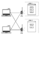
図6を用いて、本開示の実施形態に係るカスタマイズ画面の生成方法について説明する。図6は、本開示の実施形態に係るカスタマイズ画面の生成方法を説明するための図である。
図6を用いて、本開示の実施形態に係るカスタマイズ画面の生成方法について説明する。図6は、本開示の実施形態に係るカスタマイズ画面の生成方法を説明するための図である。
以下では、情報処理装置100と、無線機200とは、図1に示したように、有線又は無線のネットワークNWを介して、互いに通信可能に接続された状態であるものとして説明する。
図6に示すように、GUI画面IM3は、デフォルト画面IM31と、カスタマイズ画面IM32とを含む。
デフォルト画面IM31には、無線機200に対する設定項目が全て含まれる。なお、説明の簡単のため、デフォルト画面IM31には、ボタンAと、ボタンBと、ボタンCと、ボタンDとの4つのボタンが含まれるものとして説明する。ボタンA~ボタンDには、図4で示したような各種の設定項目に対応する機能が割り当てられている。
カスタマイズ画面IM32には、無線機200に応じてユーザによって選択された設定項目のみが含まれる。ユーザは、例えば、マウス等で構成された操作部110を用いて必要なボタンをデフォルト画面IM31からカスタマイズ画面IM32にドラッグアンドドロップすることで、ボタンをカスタマイズ画面IM32に配置することができる。具体的には、ユーザは、例えば、ボタンAをデフォルト画面IM31からカスタマイズ画面IM32にドラッグアンドドロップする(ステップS21)。この場合、生成部153は、ボタンAをカスタマイズ画面IM32上に生成する。また、ユーザは、例えば、ボタンBをデフォルト画面IM31からカスタマイズ画面IM32にドラッグアンドドロップする(ステップS22)。この場合、生成部153は、ボタンBをカスタマイズ画面IM32上に生成する。また、ユーザは、例えば、ボタンDをデフォルト画面IM31からカスタマイズ画面IM32にドラッグアンドドロップする(ステップS23)。この場合、生成部153は、ボタンDをカスタマイズ画面IM32上に生成する。これにより、カスタマイズ画面IM32には、ボタンAと、ボタンBと、ボタンDとの3つのボタンが配置される。
また、生成部153は、無線機200に応じてボタンAと、ボタンBと、ボタンDに対応する設定項目のパラメータの値を変更してもよい。すなわち、生成部153は、設定項目だけでなく、設定項目のパラメータの値も無線機200に応じたカスタマイズ画面を生成することができる。
情報処理装置100は、ボタンAと、ボタンBと、ボタンDとの3つのボタンが配置されたカスタマイズ画面IM32に関するメニュー画面構成情報を無線機200の記憶部240に記憶することができる。具体的には、記憶制御部155が、メニュー画面構成情報を記憶部240の構成ファイル記憶部241に記憶する。メニュー画面構成情報には、ボタンの種類、画面上で表示する場所の座標などの各種の情報が含まれる。このため、情報処理装置100は、構成ファイル記憶部241からメニュー画面構成情報を取得することで、無線機200に応じたカスタマイズ画面を自動で表示することができる。
図7を用いて、無線機200ごとに保存されているカスタマイズ画面を読み出す方法について説明する。図7は、無線機200ごとに保存されているカスタマイズ画面を読み出す方法を説明するための図である。
図7には、情報処理装置100Aと、情報処理装置100Bと、無線機200Aと、無線機200Bとが含まれている。情報処理装置100Aと、情報処理装置100Bとは、図3に図示の情報処理装置100と同様の構成を有している。無線機200Aと、無線機200Bとは、図5に図示の無線機200と同様の構成を有している。
無線機200Aは、ボタンAと、ボタンBと、ボタンDとが配置されたカスタマイズ画面IM32-1に関するメニュー画面構成情報を記憶部240の構成ファイル記憶部241に記憶している。無線機200Bは、ボタンAと、ボタンBとが配置されたカスタマイズ画面IM32-2に関するメニュー画面構成情報を記憶部240の構成ファイル記憶部241に記憶している。
情報処理装置100Aと、無線機200Aとが接続された場合、取得部152は、無線機200Aからカスタマイズ画面IM32-1に関するメニュー画面構成情報を取得する。この場合、表示制御部154は、カスタマイズ画面IM32-1を表示部120に表示する。また、情報処理装置100Aは、無線機200Aとの接続を解除した後、無線機200Bと接続された場合、取得部152は、無線機200Bからカスタマイズ画面IM32-2に関するメニュー画面構成情報を取得する。この場合、表示制御部154は、カスタマイズ画面IM32-2を表示部120に表示する。また、情報処理装置100Bは、情報処理装置100Aと同様の処理を実行することができる。
本開示では、無線機200Aと、無線機200Bとが、それぞれ、メニュー画面構成情報を記憶することで、情報処理装置100Aと、情報処理装置100Bとは、無線機200Aと、無線機200Bとのカスタマイズ画面を表示することができる。言い換えれば、本開示は、無線機側がメニュー画面構成情報を記憶することで、無線機に接続される情報処理装置、および情報処理装置に接続される無線機によらず、無線機に設定されたカスタマイズ画面を表示することができる。
[第1実施形態]
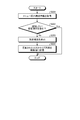
図8を用いて、本開示の第1実施形態に係る情報処理装置の処理の流れについて説明する。図8は、本開示の第1実施形態に係る情報処理装置の制御部の処理の流れの一例を示すフローチャートである。
図8を用いて、本開示の第1実施形態に係る情報処理装置の処理の流れについて説明する。図8は、本開示の第1実施形態に係る情報処理装置の制御部の処理の流れの一例を示すフローチャートである。
制御部150は、情報処理装置100に無線機が接続されたか否かを判定する(ステップS101)。具体的には、判定部151が情報処理装置100に有線又は無線のネットワークNWを介して、無線機200が接続されたか否かを判定する。無線機200が接続されたと判定されていないと判定された場合(ステップS101のNo)、制御部150は、ステップS101の処理を繰り返す。無線機200が接続されたと判定された場合(ステップS101のYes)、ステップS102に進む。
ステップS101でYesと判定された場合、制御部150は、無線機200に対してメニュー画面構成情報を要求する(ステップS102)。具体的には、取得部152が無線機200に対してメニュー画面構成情報を要求する。そして、ステップS103に進む。
制御部150は、無線機200にメニュー画面構成情報が記憶されているか否かを判定する(ステップS103)。具体的には、通信制御部156が無線機200から受けたメニュー画面構成情報の検索結果に基づいて、無線機200にメニュー画面構成情報が記憶されているか否かを判定する。メニュー画面構成情報が記憶されていると判定された場合(ステップS103のYes)、ステップS104に進む。メニュー画面構成情報が記憶されていないと判定された場合(ステップS103のNo)、ステップS106に進む。
ステップS103でYesと判定された場合、制御部150は、無線機200からメニュー画面構成情報を取得する(ステップS104)。具体的には、取得部152が構成ファイル記憶部241に記憶されたメニュー画面構成情報を取得する。そして、ステップS105に進む。
制御部150は、無線機200のカスタマイズ画面を表示する(ステップS105)。具体的には、表示制御部154が取得部152によって取得されたメニュー画面構成情報に基づいて、カスタマイズ画面を表示部120に表示する。そして、図8の処理は終了する。
ステップS103でNoと判定された場合、制御部150は、デフォルト画面を表示する(ステップS106)。具体的には、表示制御部154が、デフォルト画面を表示部120に表示する。
上述のとおり、本実施形態は、メニュー画面構成情報を無線機側に記憶することで、接続する情報処理装置(コンピュータ)や、接続する無線機によらず、それぞれの無線機に適したカスタマイズ画面を自動的に構成することができる。
また、本実施形態は、無線機に必要な項目のみが含まれるカスタマイズ画面を表示することができるので、設定を変更するためボタンを探しやすくなるため、操作性が向上する。
[第2実施形態]
図9を用いて、本開示の第2実施形態に係る情報処理システム1の処理について説明する。図9は、本開示の第2実施形態に係る情報処理システム1の処理を説明するための図である。
図9を用いて、本開示の第2実施形態に係る情報処理システム1の処理について説明する。図9は、本開示の第2実施形態に係る情報処理システム1の処理を説明するための図である。
第2実施形態では、情報処理システム1は、無線機200に設定したカスタマイズ画面に含まれる設定項目を変更する。具体的には、情報処理システム1は、無線機200に設定したカスタマイズ画面に含まれる設定項目に追加または削除をする場合に、デフォルト画面IM31の選択可能な複数の設定項目から事前設定項目として予め選択した設定項目をカスタマイズ画面IM32Aに表示させた後に、無線機200のメニュー画面構成情報を取得する。以下では、変更する設定項目が、ボタンCである場合について説明する。
図9に示すように、GUI画面IM3Aは、デフォルト画面IM31と、カスタマイズ画面IM32Aとを含む。
ユーザは、例えば、変更したい設定項目(変更項目とも呼ばれる)であるボタンCをデフォルト画面IM31からカスタマイズ画面IM32Aにドラッグアンドドロップする(ステップS31)。この場合、生成部153は、ボタンCをカスタマイズ画面IM32A上に生成する。
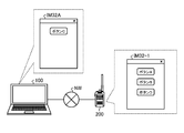
図10Aと、図10Bと、図10Cとを用いて、カスタマイズ画面に設定項目を追加する方法について説明する。図10Aと、図10Bと、図10Cとは、カスタマイズ画面に設定項目を追加する方法を説明するための図である。
図10Aには、情報処理装置100と、無線機200とが示されている。情報処理装置100は、ボタンCのみがカスタマイズ画面IM32Aに表示されている。無線機200は、ボタンAと、ボタンBと、ボタンDとを含むカスタマイズ画面IM32-1に関するメニュー画面構成情報を記憶している。
カスタマイズ画面IM32-1にボタンCを追加する場合、情報処理装置100にボタンCを含むカスタマイズ画面IM32Aを表示させた状態で、情報処理装置100と、無線機200とを、ネットワークNWを介して接続させる。これにより、情報処理装置100の取得部152は、無線機200からカスタマイズ画面IM32-1に関するメニュー画面構成情報を取得する。
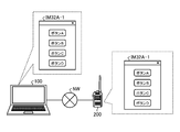
次いで、図10Bに示すように、生成部153は、取得部152によって取得されたカスタマイズ画面IM32-1に関するメニュー画面構成情報に基づいて、カスタマイズ画面IM32A-1を生成する。具体的には、生成部153は、カスタマイズ画面IM32-1にボタンCを追加して、カスタマイズ画面IM32A-1を生成する。言い換えれば、生成部153は、カスタマイズ画面IM32-1を更新する。そして、記憶制御部155は、カスタマイズ画面IM32A-1に関するメニュー画面構成情報を無線機200に記憶する。
次いで、図10Cに示すように、情報処理装置100と、無線機200との接続が解除されると、情報処理装置100には、ボタンCのみを含むカスタマイズ画面IM32Aが表示される。ここで、図10Cに示した情報処理装置100に、図7に図示の無線機200Bが接続された場合、カスタマイズ画面IM32-2には、ボタンCが追加される。以後、情報処理装置100に、カスタマイズ画面にボタンCを追加したい無線機を接続することで、図10A~図10Cに示したように、カスタマイズ画面にボタンCを追加することができる。
なお、図10A~図10Cにおいて、無線機200から取得したメニュー画面構成情報に対応するカスタマイズ画面にボタンCが含まれている場合には、情報処理装置100は、カスタマイズ画面の更新は行わない。
また、図10A~図10Cでは、設定項目を追加する場合について説明したが、本開示はこれに限られない。例えば、情報処理装置100は、無線機200に対してパラメータを変更したい画面を表示させた状態で無線機200が接続されることで、パラメータの値を更新するようにしてもよい。具体的には、生成部153が、取得部152によって取得されたカスタマイズ画面IM32-1に関するメニュー画面構成情報に基づいて、設定項目のパラメータを変更するようにしてもよい。
図11を用いて、情報処理装置の制御部がカスタマイズ画面に設定項目を追加する処理の流れについて説明する。図11は、情報処理装置の制御部がカスタマイズ画面に設定項目を追加する処理の流れの一例を示すフローチャートである。
まず、制御部150は、情報処理装置100に接続された無線機200からカスタマイズ画面に関するメニュー画面構成情報を取得する(ステップS201)。具体的には、取得部152が無線機200からメニュー画面構成情報を取得する。そして、ステップS202に進む。
制御部150は、カスタマイズ画面に追加したい設定項目が含まれているか否かを判定する(ステップS202)。具体的には、生成部153がカスタマイズ画面に追加したい設定項目が含まれているか否かを判定する。追加したい設定項目が含まれていると判定された場合(ステップS202のYes)、図11の処理は終了する。追加したい設定項目が含まれていないと判定された場合(ステップS202のNo)、ステップS203に進む。
ステップS202でNoと判定された場合、制御部150は、カスタマイズ画面に追加したい設定項目を追加する(ステップS203)。具体的には、生成部153が追加したい設定項目をカスタマイズ画面に追加して、更新する。そして、ステップS204に進む。
制御部150は、更新されたカスタマイズ画面に関するメニュー画面構成情報を無線機200に記憶する(ステップS204)。具体的には、記憶制御部155が、無線機200の記憶部240の構成ファイル記憶部241に記憶する。そして、図11の処理を終了する。
図12Aと、図12Bと、図12Cとを用いて、カスタマイズ画面から設定項目を削除する方法について説明する。図12Aと、図12Bと、図12Cとは、カスタマイズ画面から設定項目を削除する方法を説明するための図である。
図12Aには、情報処理装置100と、無線機200とが示されている。情報処理装置100は、ボタンCのみをカスタマイズ画面IM32Aが表示されている。無線機200は、ボタンAと、ボタンBと、ボタンCと、ボタンDとを含むカスタマイズ画面IM32-3に関するメニュー画面構成情報を記憶している。
カスタマイズ画面IM32-3からボタンCを削除する場合、情報処理装置100にボタンCを含むカスタマイズ画面IM32Aを表示させた状態で、情報処理装置100と、無線機200とを、ネットワークNWを介して接続させる。これにより、情報処理装置100の取得部152は、無線機200からカスタマイズ画面IM32-3に関するメニュー画面構成情報を取得する。
次いで、図12Bに示すように、生成部153は、取得部152によって取得されたカスタマイズ画面IM32-3に関するメニュー画面構成情報に基づいて、カスタマイズ画面IM32A-2を生成する。具体的には、生成部153は、カスタマイズ画面IM32-3からボタンCを削除して、カスタマイズ画面IM32A-2を生成する。言い換えれば、生成部153は、カスタマイズ画面IM32-3を更新する。そして、記憶制御部155は、カスタマイズ画面IM32A-2に関するメニュー画面構成情報を無線機200に記憶する。
次いで、図12Cに示すように、情報処理装置100と、無線機200との接続が解除されると、情報処理装置100には、ボタンCのみを含むカスタマイズ画面IM32Aが表示される。ここで、設定項目を追加する場合と同様に、ボタンCを含むカスタマイズ画面に関するメニュー画面構成情報が記憶された無線機を図11Cに示した情報処理装置に接続することで、カスタマイズ画面からボタンCを削除することができる。
なお、図12A~図12Cにおいて、無線機200から取得したメニュー画面構成情報に対応するカスタマイズ画面にボタンCが含まれていない場合には、情報処理装置100は、カスタマイズ画面の更新は行わない。
図13を用いて、情報処理装置の制御部がカスタマイズ画面から設定項目を削除する処理の流れについて説明する。図13は、情報処理装置の制御部がカスタマイズ画面から設定項目を削除する処理の流れの一例を示すフローチャートである。
ステップS301およびステップS304は、ぞれぞれ、図11に図示のステップS201およびステップS204と同じなので、説明を省略する。
制御部150は、カスタマイズ画面から削除したい設定項目が含まれているか否かを判定する(ステップS302)。具体的には、生成部153がカスタマイズ画面から削除したい設定項目が含まれているか否かを判定する。削除したい設定項目が含まれていないと判定された場合(ステップS302のNo)、図13の処理は終了する。削除したい設定項目が含まれていると判定された場合(ステップS302のYes)、ステップS303に進む。
ステップS302でYesと判定された場合、制御部150は、カスタマイズ画面から削除したい設定項目を削除する(ステップS303)。具体的には、生成部153が削除したい設定項目をカスタマイズ画面から削除して、更新する。そして、ステップS304に進む。
なお、本実施形態において、カスタマイズ画面にボタンを追加したり、カスタマイズ画面からボタンを削除したりした後のボタンの配置は、特に制限なく決定してよい。例えば、カスタマイズ画面上のボタンは、予め定められた優先順位に従って配置されるようにしてもよいし、ボタンが追加された場合には追加された順番に従って配置されるようにしてもよい。また、カスタマイズ画面にボタンが追加されたり、カスタマイズ画面からボタンが削除されたりした後に、ユーザが操作部110を操作することで、カスタマイズ画面に配置されたボタンの位置を調整できるようにしてもよい。
また、本実施形態では、カスタマイズ画面にボタンを追加したり、ボタンを削除したりする場合の処理について説明したが、本開示はこれに限定されない。例えば、本開示は、テキストボックス、プルダウンメニュー、チェックボックス、およびラジオボタンなど様々なGUI要素をカスタマイズする場合にも適用することができる。
上述のとおり、本実施形態は、無線機200に対する設定項目を含むカスタマイズ画面のボタンを追加したり、カスタマイズ画面からボタンを削除したりすることを容易に行うことができる。そのため、本実施形態は、無線機200の設定項目を含む適切なカスタマイズ画面をより容易に作成することができる。
本実施形態の情報処理装置、情報処理方法、およびプログラムは、例えば、表示画面を有する電子機器に利用することができる。
1 情報処理システム
100 情報処理装置
110,210 操作部
120,220 表示部
130,230 通信部
140,240 記憶部
150,250 制御部
151 判定部
152,251 取得部
153 生成部
154,253 表示制御部
155 記憶制御部
156,254 通信制御部
200 無線機
241 構成ファイル記憶部
252 検索部
100 情報処理装置
110,210 操作部
120,220 表示部
130,230 通信部
140,240 記憶部
150,250 制御部
151 判定部
152,251 取得部
153 生成部
154,253 表示制御部
155 記憶制御部
156,254 通信制御部
200 無線機
241 構成ファイル記憶部
252 検索部
Claims (6)
- 電子機器が接続された際に、前記電子機器に記憶された所定の設定項目を含むメニュー画面構成情報を取得する取得部と、
取得された前記メニュー画面構成情報を、選択可能な複数の設定項目から接続された電子機器に応じて選ばれた設定項目に基づいて変更する生成部と、
前記生成部において変更された前記メニュー画面構成情報を前記電子機器に記憶させる記憶制御部と、
を備える、情報処理装置。 - 前記電子機器が接続された際に、前記取得部において前記メニュー画面構成情報が取得できなかった場合、
前記生成部は、選択可能な複数の設定項目から接続された電子機器に応じて選ばれた設定項目に基づいて新たなメニュー画面構成情報を生成する、
請求項1に記載の情報処理装置。 - 選択可能な複数の設定項目から予め事前設定項目が選ばれている場合、
前記生成部は、取得された前記メニュー画面構成情報を、前記事前設定項目に基づいて変更する
請求項1に記載の情報処理装置。 - 前記生成部は、前記メニュー画面構成情報によりメニュー画面を構成して接続された前記電子機器を設定可能とする
請求項1から3のいずれか1項に記載の情報処理装置。 - 電子機器が接続された際に、前記電子機器に記憶された所定の設定項目を含むメニュー画面構成情報を取得するステップと、
取得された前記メニュー画面構成情報を、選択可能な複数の設定項目から接続された電子機器に応じて選ばれた設定項目に基づいて変更するステップと、
変更された前記メニュー画面構成情報を前記電子機器に記憶させるステップと、
含む、情報処理方法。 - 電子機器が接続された際に、前記電子機器に記憶された所定の設定項目を含むメニュー画面構成情報を取得するステップと、
取得された前記メニュー画面構成情報を、選択可能な複数の設定項目から接続された電子機器に応じて選ばれた設定項目に基づいて変更するステップと、
変更された前記メニュー画面構成情報を前記電子機器に記憶させるステップと、
をコンピュータに実行させるためのプログラム。
Priority Applications (1)
| Application Number | Priority Date | Filing Date | Title |
|---|---|---|---|
| US17/539,244 US11782578B2 (en) | 2019-06-20 | 2021-12-01 | Information processing device, information processing method, and non-transitory storage medium for configuring menu screen configuration of a connected device |
Applications Claiming Priority (2)
| Application Number | Priority Date | Filing Date | Title |
|---|---|---|---|
| JP2019114291A JP7172873B2 (ja) | 2019-06-20 | 2019-06-20 | 情報処理装置、情報処理方法、およびプログラム |
| JP2019-114291 | 2019-06-20 |
Related Child Applications (1)
| Application Number | Title | Priority Date | Filing Date |
|---|---|---|---|
| US17/539,244 Continuation US11782578B2 (en) | 2019-06-20 | 2021-12-01 | Information processing device, information processing method, and non-transitory storage medium for configuring menu screen configuration of a connected device |
Publications (1)
| Publication Number | Publication Date |
|---|---|
| WO2020255673A1 true WO2020255673A1 (ja) | 2020-12-24 |
Family
ID=73995080
Family Applications (1)
| Application Number | Title | Priority Date | Filing Date |
|---|---|---|---|
| PCT/JP2020/021249 Ceased WO2020255673A1 (ja) | 2019-06-20 | 2020-05-28 | 情報処理装置、情報処理方法、およびプログラム |
Country Status (3)
| Country | Link |
|---|---|
| US (1) | US11782578B2 (ja) |
| JP (1) | JP7172873B2 (ja) |
| WO (1) | WO2020255673A1 (ja) |
Families Citing this family (1)
| Publication number | Priority date | Publication date | Assignee | Title |
|---|---|---|---|---|
| JP2024157961A (ja) * | 2023-04-26 | 2024-11-08 | キヤノン株式会社 | 情報処理装置及びその制御方法及びプログラム |
Citations (1)
| Publication number | Priority date | Publication date | Assignee | Title |
|---|---|---|---|---|
| JP2017011517A (ja) * | 2015-06-23 | 2017-01-12 | 株式会社リコー | 機器、情報処理システム、情報処理方法、及びプログラム |
Family Cites Families (4)
| Publication number | Priority date | Publication date | Assignee | Title |
|---|---|---|---|---|
| JP2005018165A (ja) | 2003-06-23 | 2005-01-20 | Ricoh Co Ltd | データ処理装置、プログラム及び記録媒体 |
| US20080141148A1 (en) * | 2006-12-08 | 2008-06-12 | Ogita Seiya | Image forming device and display control method |
| KR101352248B1 (ko) * | 2007-08-30 | 2014-01-16 | 삼성전자주식회사 | 사용자 인터페이스 자동 전환 장치 및 방법 |
| US20130159917A1 (en) * | 2011-12-20 | 2013-06-20 | Lenovo (Singapore) Pte. Ltd. | Dynamic user interface based on connected devices |
-
2019
- 2019-06-20 JP JP2019114291A patent/JP7172873B2/ja active Active
-
2020
- 2020-05-28 WO PCT/JP2020/021249 patent/WO2020255673A1/ja not_active Ceased
-
2021
- 2021-12-01 US US17/539,244 patent/US11782578B2/en active Active
Patent Citations (1)
| Publication number | Priority date | Publication date | Assignee | Title |
|---|---|---|---|---|
| JP2017011517A (ja) * | 2015-06-23 | 2017-01-12 | 株式会社リコー | 機器、情報処理システム、情報処理方法、及びプログラム |
Also Published As
| Publication number | Publication date |
|---|---|
| JP2021002109A (ja) | 2021-01-07 |
| JP7172873B2 (ja) | 2022-11-16 |
| US20220091705A1 (en) | 2022-03-24 |
| US11782578B2 (en) | 2023-10-10 |
Similar Documents
| Publication | Publication Date | Title |
|---|---|---|
| JP4342578B2 (ja) | 情報処理装置およびプログラム | |
| CN104090700B (zh) | 应用图标管理方法及装置 | |
| CN107203147B (zh) | 基于云平台的物联网控制系统和方法 | |
| US11716244B2 (en) | Data driven user interface for configuring device settings | |
| WO2012142051A2 (en) | Graphical user interface with customized navigation | |
| CN105930020A (zh) | 一种管理终端应用程序的功能图标的方法及装置 | |
| CN105005439A (zh) | 图标管理方法、装置及移动终端 | |
| JP5509522B2 (ja) | 移動通信端末、及び移動通信端末のメニュー表示方法 | |
| CN111984248B (zh) | 页面编辑方法和装置、存储介质及电子装置 | |
| JP2013004081A (ja) | 携帯端末機におけるアプリケーションプログラムの併合方法及び装置 | |
| CN110768877B (zh) | 语音控制指令的处理方法、装置、电子设备及可读存储介质 | |
| JP7172873B2 (ja) | 情報処理装置、情報処理方法、およびプログラム | |
| CN103412707B (zh) | 一种显示框显示的方法、装置和设备 | |
| US10666683B2 (en) | User interface for low-touch security policy provisioning | |
| CN110888688B (zh) | 一种电子设备的设置还原方法及电子设备 | |
| CN104317561A (zh) | 一种界面操作的方法 | |
| KR102087395B1 (ko) | 전자 장치에서 응용프로그램을 실행하기 위한 장치 및 방법 | |
| CN114924494A (zh) | 智能设备的按键定义方法、装置、计算机设备、存储介质 | |
| EP3084616B1 (en) | Providing real-time feedback for information transfer | |
| CN115801846B (zh) | 一种功能性设备的控制方法、装置、电子设备及存储介质 | |
| JP6348820B2 (ja) | 携帯端末およびその制御方法 | |
| KR102591990B1 (ko) | 서버, 사용자 단말 및 이를 포함하는 통신 시스템 | |
| US20160012017A1 (en) | Methods And Systems For Page Control With Event Display | |
| GB2602848A (en) | Single Bi-directional point of policy control, administration, interactive queries, and security protections | |
| CA2989654C (en) | Method and apparatus for modifying behavior of code for a controller-based device |
Legal Events
| Date | Code | Title | Description |
|---|---|---|---|
| 121 | Ep: the epo has been informed by wipo that ep was designated in this application |
Ref document number: 20826796 Country of ref document: EP Kind code of ref document: A1 |
|
| NENP | Non-entry into the national phase |
Ref country code: DE |
|
| 122 | Ep: pct application non-entry in european phase |
Ref document number: 20826796 Country of ref document: EP Kind code of ref document: A1 |