WO2020250885A1 - Dredger - Google Patents
Dredger Download PDFInfo
- Publication number
- WO2020250885A1 WO2020250885A1 PCT/JP2020/022680 JP2020022680W WO2020250885A1 WO 2020250885 A1 WO2020250885 A1 WO 2020250885A1 JP 2020022680 W JP2020022680 W JP 2020022680W WO 2020250885 A1 WO2020250885 A1 WO 2020250885A1
- Authority
- WO
- WIPO (PCT)
- Prior art keywords
- hull
- water
- sand
- boom
- earth
- Prior art date
Links
Images


Classifications
-
- E—FIXED CONSTRUCTIONS
- E02—HYDRAULIC ENGINEERING; FOUNDATIONS; SOIL SHIFTING
- E02F—DREDGING; SOIL-SHIFTING
- E02F5/00—Dredgers or soil-shifting machines for special purposes
- E02F5/28—Dredgers or soil-shifting machines for special purposes for cleaning watercourses or other ways
-
- E—FIXED CONSTRUCTIONS
- E02—HYDRAULIC ENGINEERING; FOUNDATIONS; SOIL SHIFTING
- E02F—DREDGING; SOIL-SHIFTING
- E02F7/00—Equipment for conveying or separating excavated material
- E02F7/04—Loading devices mounted on a dredger or an excavator hopper dredgers, also equipment for unloading the hopper
-
- E—FIXED CONSTRUCTIONS
- E02—HYDRAULIC ENGINEERING; FOUNDATIONS; SOIL SHIFTING
- E02F—DREDGING; SOIL-SHIFTING
- E02F3/00—Dredgers; Soil-shifting machines
- E02F3/04—Dredgers; Soil-shifting machines mechanically-driven
- E02F3/46—Dredgers; Soil-shifting machines mechanically-driven with reciprocating digging or scraping elements moved by cables or hoisting ropes ; Drives or control devices therefor
- E02F3/47—Dredgers; Soil-shifting machines mechanically-driven with reciprocating digging or scraping elements moved by cables or hoisting ropes ; Drives or control devices therefor with grab buckets
-
- E—FIXED CONSTRUCTIONS
- E02—HYDRAULIC ENGINEERING; FOUNDATIONS; SOIL SHIFTING
- E02F—DREDGING; SOIL-SHIFTING
- E02F3/00—Dredgers; Soil-shifting machines
- E02F3/04—Dredgers; Soil-shifting machines mechanically-driven
- E02F3/88—Dredgers; Soil-shifting machines mechanically-driven with arrangements acting by a sucking or forcing effect, e.g. suction dredgers
- E02F3/8833—Floating installations
- E02F3/8841—Floating installations wherein at least a part of the soil-shifting equipment is mounted on a ladder or boom
-
- E—FIXED CONSTRUCTIONS
- E02—HYDRAULIC ENGINEERING; FOUNDATIONS; SOIL SHIFTING
- E02F—DREDGING; SOIL-SHIFTING
- E02F3/00—Dredgers; Soil-shifting machines
- E02F3/04—Dredgers; Soil-shifting machines mechanically-driven
- E02F3/88—Dredgers; Soil-shifting machines mechanically-driven with arrangements acting by a sucking or forcing effect, e.g. suction dredgers
- E02F3/8833—Floating installations
- E02F3/885—Floating installations self propelled, e.g. ship
-
- E—FIXED CONSTRUCTIONS
- E02—HYDRAULIC ENGINEERING; FOUNDATIONS; SOIL SHIFTING
- E02F—DREDGING; SOIL-SHIFTING
- E02F3/00—Dredgers; Soil-shifting machines
- E02F3/04—Dredgers; Soil-shifting machines mechanically-driven
- E02F3/88—Dredgers; Soil-shifting machines mechanically-driven with arrangements acting by a sucking or forcing effect, e.g. suction dredgers
- E02F3/90—Component parts, e.g. arrangement or adaptation of pumps
- E02F3/907—Measuring or control devices, e.g. control units, detection means or sensors
-
- E—FIXED CONSTRUCTIONS
- E02—HYDRAULIC ENGINEERING; FOUNDATIONS; SOIL SHIFTING
- E02F—DREDGING; SOIL-SHIFTING
- E02F3/00—Dredgers; Soil-shifting machines
- E02F3/04—Dredgers; Soil-shifting machines mechanically-driven
- E02F3/88—Dredgers; Soil-shifting machines mechanically-driven with arrangements acting by a sucking or forcing effect, e.g. suction dredgers
- E02F3/90—Component parts, e.g. arrangement or adaptation of pumps
- E02F3/92—Digging elements, e.g. suction heads
- E02F3/9212—Mechanical digging means, e.g. suction wheels, i.e. wheel with a suction inlet attached behind the wheel
- E02F3/9225—Mechanical digging means, e.g. suction wheels, i.e. wheel with a suction inlet attached behind the wheel with rotating cutting elements
-
- E—FIXED CONSTRUCTIONS
- E02—HYDRAULIC ENGINEERING; FOUNDATIONS; SOIL SHIFTING
- E02F—DREDGING; SOIL-SHIFTING
- E02F5/00—Dredgers or soil-shifting machines for special purposes
- E02F5/28—Dredgers or soil-shifting machines for special purposes for cleaning watercourses or other ways
- E02F5/282—Dredgers or soil-shifting machines for special purposes for cleaning watercourses or other ways with rotating cutting or digging tools
-
- E—FIXED CONSTRUCTIONS
- E02—HYDRAULIC ENGINEERING; FOUNDATIONS; SOIL SHIFTING
- E02F—DREDGING; SOIL-SHIFTING
- E02F7/00—Equipment for conveying or separating excavated material
- E02F7/10—Pipelines for conveying excavated materials
Definitions
- a bucket device is suspended from a dredging work vessel, particularly a boom pivotally supported on the hull, via a wire that can be wound and unwound by a winch device provided on the hull, and the bottom of the water is suspended by this bucket device. It relates to a dredging work vessel that can scrape and excavate the earth and sand of the earth and can be pumped to the earth and sand storage place on the water through the earth and sand transport pipe.
- the dredging work vessel described above is conventionally known as disclosed in Patent Document 1 below.
- a heavy bucket device is suspended by a wire to move up and down, so that the bottom of the water is utilized by utilizing the weight of the bucket device itself. It has the advantage of being able to efficiently scrape and excavate earth and sand.
- the hull is fixed to the bottom of the water by a fixing means such as a spud to perform the dredging work. Therefore, each time the dredging work range (position) is changed, the fixing means is used. It is necessary to repeatedly perform the work of releasing the operation, moving the hull, and fixing the position after the movement to the bottom of the water again by the fixing means, which is troublesome to change.
- the present invention has been proposed in view of the above, and first solves the above-mentioned problems associated with the use of a wire that hangs long from the water surface to near the bottom of the water while taking advantage of the bucket device suspended from the wire.
- the second purpose is to enable the dredging work to be performed over a wide range and with high accuracy without fixing the hull to the bottom of the water.
- the present invention hangs a wire that can be wound and unwound by a winch device provided on the hull from the tip of a boom that is pivotally supported on the hull.
- a winch device provided on the hull from the tip of a boom that is pivotally supported on the hull.
- the boom moves up and down in the water.
- the first feature is that the wire is configured to be tiltable in a direction and the wire can hang down from the tip of the boom in water.
- the present invention can propel the hull along the water surface in order to adjust the horizontal position of the bucket device in water.
- the hull propulsion device is provided so that the bucket device can move the excavation target section of the bottom of the water along a predetermined excavation route.
- the second feature is to include a control device capable of controlling the operation and controlling the position of the hull.
- the bucket device injects pressurized air and / or pressurized water into the excavated earth and sand that has been scraped into the bucket device.
- a third feature is that it is provided with a sediment flow assisting device that assists the flow of sediment toward the sediment storage place via the sediment transport pipe.
- the present invention has, in addition to any of the first to third features, a fourth feature that the hull is provided with a sediment storage tank serving as the sediment storage place.
- the boom pivotally supported on the hull is configured to be able to tilt in the water in the vertical direction, and the wire unwound from the winch device on the hull hangs down from the tip of the boom in the water and buckets. Since the device is suspended, the hanging length of the wire from the tip of the boom to the bucket device can be sufficiently shortened while taking advantage of the bucket device by suspending the wire, and the wire can be blown on the water surface. It is possible to eliminate or reduce the influence of waves and waves, and the influence of currents in water.
- the deviation of the horizontal position of the bucket device with respect to the hull position (hence, the horizontal position of the boom tip) can be reduced, so that the accuracy of the position control of the bucket device based on the position control of the hull (hence the boom) can be improved.
- a hull propulsion device capable of driving the hull along the water surface in order to adjust the horizontal position of the bucket device in water and a control device for controlling the operation of the hull propulsion device are provided and controlled.
- the device operates the hull propulsion device based on the GPS position information of at least one of the hull, the boom and the bucket device to control the hull position, so that the bucket device sets the excavation target section of the water bottom into a predetermined excavation route. It will be possible to move along.
- the bucket device can move the excavation target section of the water bottom along a predetermined excavation route by using the GPS position information as a clue without fixing the hull to the water bottom. Therefore, the bucket device can be used over a wide range of the water bottom.
- the dredging work can be performed evenly. Moreover, the position control of the bucket device during this dredging work is accurate due to the effect of eliminating or making it difficult to receive the influence of waves and tidal currents by hanging the wire from the tip of the boom in water as described above. It will be possible to execute well.
- the third feature by injecting pressurized air and / or pressurized water into the excavated earth and sand that has been scraped into the bucket device, the flow of earth and sand from the bucket device to the earth and sand storage place via the earth and sand transport pipe is assisted. Since it is equipped with a sediment flow assisting device, even if the bucket device is left in the water, the excavated sediment that has been scraped into the bucket device is diffused to increase the fluidity, and it is smoothly forced to the sediment storage place on the water through the sediment transport pipe. Can be transported.
- the dredging work vessel since the dredging work vessel is provided with a sediment storage tank, the dredging work vessel itself can store the dredging sediment without having to put the soil carrier sideways on the dredging work vessel. , Dredging work can be continued even if there is no soil carrier, and even when the dredging work is interrupted due to a failure of the bucket device etc., the earth and sand accumulated in the dredging work ship can be transshipped to the soil carrier. , Work efficiency is improved as a whole.
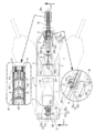
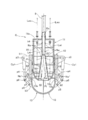
- FIG. 1 is an overall side view showing a dredging work vessel according to the first embodiment of the present invention.
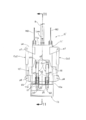
- FIG. 2 is a plan view of a main part of the dredging work vessel (cross-sectional view taken along line 2-2 of FIG. 1), a partially enlarged plan view, and a partially enlarged perspective view.
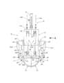
- FIG. 3 is a front view of the grab bucket (enlarged view of the three arrow viewing portion of FIG. 1).
- FIG. 4 is a side view of the grab bucket (4 arrow view of FIG. 3).
- FIG. 5 is a vertical cross-sectional view (5-5 line cross-sectional view of FIG. 4) of the grab bucket viewed in the same direction as that of FIG.
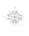
- FIG. 6 is a plan view of the grab bucket (6 arrow view of FIG. 5).
- FIG. 5 is a vertical cross-sectional view (5-5 line cross-sectional view of FIG. 4) of the grab bucket viewed in the same direction as that of FIG.
- FIG. 6 is a plan view of the
- FIG. 7 is a cross-sectional view corresponding to FIG. 5 showing the relationship between the grab bucket at the position of the alternate long and short dash line in FIG. 1 and the bottom of the water.
- FIG. 8 is a process diagram showing an example of the closing process of the grab bucket.
- FIG. 9 is a cross-sectional view corresponding to FIG. 5 showing a modified example of the extension plate portion.
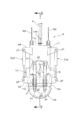
- FIG. 10 is a side view (corresponding to FIG. 4) of the grab bucket according to the second embodiment.
- FIG. 11 is a sectional view taken along line 11-11 of FIG. 10 (corresponding to FIG. 5).
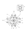
- FIG. 12 is a plan view (corresponding to FIG. 6) of the grab bucket according to the second embodiment.
- the dredging work vessel S has a hull 1 floating on the water surface, for example, a hull propulsion device D capable of propelling the hull 1 along the water surface, and can swing (tilt) vertically with respect to the hull 1.
- the boom B is pivotally supported, the first wire W1 whose one end is connected to the tip Ba of the boom B, and the other end side of the first wire W1 provided on the hull 1 can be wound and unwound.
- a first winch device M1 for tilting the boom, a grab bucket G as a bucket device suspended from the tip Ba of the boom B via a second wire W2, and a second wire W2 provided on the hull 1 are wound. It is provided with a second winch device M2 for raising and lowering a bucket that can be taken out and taken out, and a pair of left and right sediment storage tanks 3 installed on the hull 1 to form a sediment storage place on the water.
- the first winch device M1 includes a drum capable of winding the first wire W1 and a motor for rotationally driving the drum. Then, by winding or unwinding the first wire W1 by the first winch device M1, the boom B connected to the wire W1 can be tilted upward or downward.
- the second winch device M2 includes a drum capable of winding the second wire W2 and a motor for rotationally driving the drum. Then, by winding or unwinding the second wire W2 by the second winch device M2, the grab bucket G suspended from the wire W2 can be raised or lowered.
- the first and second wires W1 and W2 are provided in pairs on the left and right, but may be one each or three or more each.
- the grab bucket G is configured so that the earth and sand 4 on the bottom E can be squeezed and excavated, and the excavated earth and sand squeezed into the grab bucket G is a flexible earth and sand transport pipe. It is pumped to the earth and sand storage tank 3 on the water through 8. Therefore, in the dredging work, it is not necessary to pull up the grab bucket G to the water one by one, and the work efficiency can be improved.
- the grab bucket G is an example of the bucket device of the present invention. The specific structure of the grab bucket G will be described later.
- the base end portion Bb of the boom B is pivotally supported by the carriage portion 5b of the movable support 5 mounted on the front portion of the hull 1 so as to be movable only back and forth, and the boom B is provided around the shaft support p1 portion. It can swing up and down not only on the water but also in the water.
- the bogie portion 5b has a notch-shaped boom relief portion 5bk for avoiding interference between the boom B and the movable support 5 regardless of the tilting posture of the boom B. have.
- the movable support 5 is interlocked with a drive device provided between the bogie portion 5b and the hull 1 thereof, and can be driven back and forth on the hull 1 together with the base end portion Bb of the boom B.
- a motor for example, as shown in FIG. 2, a motor (not shown) is a drive wheel 5w with a brake mechanism that is axially supported by the trolley portion 5b and can travel along a guide rail 9 fixed to the hull 1. It is possible to adopt a structure in which deceleration is driven by a motor, or a structure in which a pinion with a brake mechanism that meshes with a rack fixed to the hull 1 and is pivotally supported by the trolley portion 5b is decelerated and driven by a motor, although not shown.
- the boom B is in a state of projecting to the frontmost side as shown in FIG. 1, and has an upward swing limit standing above the water surface and below the water surface. It is possible to swing up and down with the downward swing limit that sinks in.
- the front end of the hull 1 is provided with a relief portion 1a for allowing the boom B to swing to the downward swing limit in water, and the relief portion 1a is opened upward / downward and forward. It is formed in a notch shape.
- a support frame 6 formed in a gate shape so as to straddle the front-back movement locus of the movable support 5 is erected.
- a first guide roller r1 that guides and passes through an intermediate portion of the first wire W1 unwound from the first winch device M1 is rotatably supported on the upper portion of the support frame 6.
- the intermediate portion of the second wire W2 unwound from the second winch device M2 is rotatably supported by the second guide roller r2 supported by the movable support 5 and the front and rear portions rotatably supported by the tip portion Ba of the boom B. It is guided by and passed through the pair of third guide rollers r3, and hangs down from the tip Ba of the boom B.
- the second guide roller r2 is pivotally supported by the upper end portion of the support base 5a erected on the carriage portion 5b of the movable support 5. Further, the pair of front and rear third guide rollers r3 allow the second wire W2 to pass between them.
- the grab bucket G is formed of a bottomed cylindrical main frame 11 and a cylindrical shape with open upper and lower ends, and is slidably fitted to the outer periphery of the main frame 11 via a plurality of annular seal members 18.
- the base is pivoted to the lower end of the elevating cylinder 12 via hinge brackets b2 and b3 so that the elevating cylinder 12 as an elevating body and the open lower end of the elevating cylinder 12 can be opened and closed to scrape the earth and sand 4 of the water bottom E inside.
- a pair of squeezing plates 13 connected to each other (shaft support) p2, a first hydraulic cylinder Cy1 as an opening / closing drive device for opening / closing both squeezing plates 13, and an elevating cylinder 12 are driven up / down with respect to the main frame 11.
- the second hydraulic cylinder Cy2 as an elevating drive device and the other end Po are connected to the upstream end of the earth and sand transport pipe 8 by opening Pi at one end in the bottom wall 11b of the main frame 11 and fixed in the main frame 11.
- a check valve 15 for preventing the backflow of the earth and sand 4 pushed out from the sand discharge pipe P to the earth and sand transport pipe 8 side is provided.
- the annular seal member 18 is fitted into an annular groove provided on either one of the facing peripheral surfaces of the main frame 11 and the elevating cylinder 12, and is in sliding contact with the other of the opposing peripheral surfaces.
- the upper end wall 11a of the main frame 11 is connected and supported at the free end, that is, the lower end of the second wire W2. Then, the second wire W2 can drive the main frame 11 (hence, the grab bucket G) in the horizontal direction and the vertical direction in water in conjunction with the movements of the hull 1, the second winch device M2, and the boom B.
- the lower end wall of the main frame 11, that is, the bottom wall 11b is formed in the shape of a hemispherical plate that is curved downward, and a sand drain pipe is formed at the central portion of the bottom wall 11b, that is, the central top of the hemispherical surface that bulges downward.
- the large-diameter lower end (that is, one end of the sand drain pipe P) Pi of the truncated cone-shaped lower half pipe portion of P is opened and fixed.
- the upper half pipe portion of the sand removal pipe P is formed in a cylindrical shape, and the lower end of the upper half pipe portion is integrally connected to the small diameter upper end of the lower half pipe portion, and the upper end of the upper half pipe portion (that is, The other end of the sand removal pipe P) is connected to the upstream end of the earth and sand transport pipe 8 via a joint.
- the intermediate portion of the sand removal pipe P is fixed and supported on the inner peripheral wall of the main frame 11 via a plurality of support plates 16, and the upper portion penetrates and is fixed to the upper end wall 11a of the main frame.
- the check valve 15 prevents the backflow of earth and sand downward, and in the illustrated example, only one check valve 15 is installed in the upper half pipe portion of the sand drain pipe P, but the number of check valves 15 installed and the installation
- the site and the valve body structure are not limited to the embodiments and can be appropriately set.
- the check valve 15 may be installed in the vicinity of the lower end Pi of the lower half pipe portion of the sand removal pipe P or in the intermediate portion.
- the check valve 15 of the present embodiment has a valve structure having a single leaf valve body of a single opening type, but in particular, a large diameter portion of the sand drain pipe P (for example, near or in the middle of the lower end Pi of the lower half pipe portion).
- a valve structure having a pair of double-door (that is, double-door) leaf valve bodies may be used.
- the inner surface of the sand drain pipe P is a valve for avoiding interference with the valve body of the check valve 15 and ensuring smooth opening and closing operation of the valve body. It is desirable to recess the body escape part (not shown).
- a stopper protrusion (not shown) capable of engaging with the valve body is provided so that the valve body of the check valve 15 does not open downward from the fully closed position and rotate. Provided.
- the pair of scraping plates 13 have a symmetrical shape with each other, and in a state where both are closed (see FIGS. 3 and 5), the pair of scraping plates 13 have a hemispherical plate shape that is close to and faces the lower surface of the hemispherical plate-shaped bottom wall 11b of the main frame 11. (That is, the hemispherical plate is further divided into two equal parts). Then, the excavated earth and sand 4 scraped by both scraping plates 13 is forcibly pushed into the sand removal pipe P by driving the elevating cylinder 12 upward with respect to the main frame 11 with the scraping plates 13 closed. ..
- edge portions that serve as the mating surfaces of the pair of scraping plates 13 are formed in a slightly tapered cross section in order to make it difficult for earth and sand to be pinched when both scraping plates 13 are closed. If necessary, a plurality of claws capable of efficiently crushing the bottom sediment may be alternately fixed to the edge portions (particularly the lower end edge portion) of both scraping plates 13.
- a base portion of a short cylindrical extension plate portion 12a extending downward from the lower end of the elevating cylinder 12 is continuously provided, and the tip, that is, the lower end of the extension plate portion 12a is scratched.
- the insert plate 13 is closed, it comes into contact with the upper end edges of both suction plates 13.
- the gap between the lower end edge of the elevating cylinder 12 and the upper end edge of both the suction plates 13 in the fully closed state can be made substantially zero or small, which is compatible with the sealing effect of the annular sealing member 18 described above.
- the space 40 between the fully closed both scraping plates 13 and the bottom wall 11b of the main frame 11 can be made substantially sealed, and the excavated earth and sand and the earth and sand flow assisting device A described later can be applied through the gap. It is possible to effectively suppress the leakage of pressurized air and pressurized water to the outside.
- the tip of the extension plate portion 12a is directly in contact with the upper end edge of both the suction plates 13 in the fully closed state, but the tip of the extension plate portion 12a and the both suction plates 13 in the fully closed state are brought into direct contact with each other.
- a sealing member (not shown) made of an elastic material (for example, a rubber material) may be attached to at least one of the upper end edges of the space 40, and in this case, the sealing effect of the space 40 can be further enhanced. It becomes.
- the extension plate portion 12a is formed integrally with the main body portion of the elevating cylinder 12, but the extension plate portion 12a is formed separately from the main body portion of the elevating cylinder 12 and is retrofitted. It may be fixed (for example, welded) to the elevating cylinder 12.
- FIG. 9 shows a modified example of the extension plate portion.
- a base portion of an arc plate-shaped extension plate portion 13a extending upward from the upper end of each scraping plate 13 is continuously provided at the upper end portion of each scraping plate 13, and the extension plate portion 13a is provided.
- the tip, that is, the upper end of the pipe is brought into contact with the lower edge of the elevating cylinder 12 when both the scraping plates 13 are closed.
- the gap between the lower end edge of the elevating cylinder 12 and the upper end edge of both the suction plates 13 in the fully closed state. Can be substantially zero to very small.
- a seal member may be attached to the tip of the extension plate portion 13a and / or the lower end of the elevating cylinder 12, and in this case, the sealing effect of the space 40 can be further enhanced.
- the extension plate portion 13a may be formed separately from the scraping plate 13 and fixed (for example, welded) to the scraping plate 13 by retrofitting.
- a pair of first hydraulic cylinders Cy1 are installed for each of the individual scraping plates 13.
- the base end of the first hydraulic cylinder Cy1 is pivotally connected to the upper part of the outer peripheral wall of the elevating cylinder 12 via a hinge bracket b1
- the tip is a refracting link mechanism 17 composed of a pair of links that can be refracted from each other.
- a pivotal connection p6 is made to the base of each scraping plate 13 via. That is, both ends of the refraction link mechanism 17 are pivotally connected to the elevating cylinder 12 and each scraping plate 13 via hinge brackets b2 and b3, respectively, and the intermediate portion (that is, the refraction point) of the refraction link mechanism 17 is connected.
- the tip of the first hydraulic cylinder Cy1 is pivotally connected to the pivotally connected portion).
- the second hydraulic cylinder Cy2 is installed in pairs on the left and right at positions that are out of phase with the first hydraulic cylinder Cy1.
- the base end of the second hydraulic cylinder Cy2 is pivotally connected to the upper part of the outer peripheral wall of the main frame 11 via a hinge bracket b4, and the tip is connected to the lower part of the outer peripheral wall of the elevating cylinder 12 via a hinge bracket b5.
- the pivotal connection is p8.
- the first and second hydraulic cylinders Cy1 and Cy2 are supplied and controlled with their respective operating hydraulic pressures from a hydraulic control circuit including a hydraulic source and a control valve installed on the hull 1 via a flexible hydraulic pipe that passes through water. To.
- the hydraulic control circuit and the hydraulic conduit are not shown.
- a sediment flow assisting device A is provided to assist the flow of the sediment 4 toward the sediment storage place 3 through the above.
- the earth and sand flow assisting device A of the present embodiment includes a large number of air injection nozzles Na arranged and fixed inwardly at intervals in the circumferential direction and the vertical direction on the peripheral wall of the sand removal pipe P, and the same as the sand removal pipe P.
- Each of the air injection nozzle Na and the water injection nozzle Nw is arranged in a direction in which the injection port is inclined slightly downstream (upper side in the drawing) toward the axis of the sand discharge pipe P, and is injected from there. Due to the flow pressure of the pressurized air and the pressurized water, the excavated earth and sand 4 pushed into the sand discharge pipe P can be efficiently diffused and efficiently pumped to the downstream side (that is, the earth and sand transport pipe 8 side).
- a plurality of air injection nozzles Na'and water injection nozzles Nw' are directed outward (more specifically) at intervals in the circumferential direction and the vertical direction. Is arranged and fixed in a direction in which the sand drain pipe P is slightly inclined downward in the radial direction.
- These air injection nozzle Na'and water injection nozzle Nw' are also connected to the air supply pipe Lai and the water supply pipe Lwi, respectively.
- the pressurized air and the pressurized water injected from the air injection nozzle Na'and the water injection nozzle Nw' are injected into the narrow space 40 between the fully closed suction plate 13 and the bottom wall 11b of the main frame 11.
- the air injection nozzle Na and the water injection nozzle Nw constitute the first injection means in the sediment flow assisting device A, and the air injection nozzle Na'and the water injection nozzle Nw' are in the sediment flow assisting device A. It constitutes a second injection means.
- the air supply pipe Lai and the water supply pipe Lwi are supplied from the air supply control device including the pressurized air source and the air control valve installed on the hull 1, and the water supply control device including the pressurized water source and the water control valve, respectively. Pressurized air and pressurized water are supplied and controlled, respectively, via the flexible air conduit Lao and the water conduit Lwo.
- the first injection means (Na, Nb) of the earth and sand flow assisting device A injects both pressurized air and pressurized water to the earth and sand 4 pushed into the sand discharge pipe P.
- the first injection means (Na, Nb) of the earth and sand flow assisting device A injects either pressurized air or pressurized water (for example, only pressurized water) to the earth and sand 4 pushed into the sand discharge pipe P. It may be a structure to be used.
- the second injection means (Na', Nb') of the earth and sand flow assisting device A is the same as the first injection means, that is, either one of the pressurized air or the pressurized water (for example, the space 40).
- a structure that injects only pressurized water) may be used.
- the downstream part of the earth and sand transport pipe 8 is wound up and unwound by a drum device 20 provided on the hull 1 near the earth and sand storage tank 3.
- This drum device 20 has a pair of left and right earth and sand outlet pipes 20a communicating with the downstream end of the earth and sand transport pipe 8, and the earth and sand conveyed through the earth and sand transport pipe 8 is a pair of left and right earth and sand outlet pipes 20a. It is put into the earth and sand storage tank 3 and stored.
- the intermediate portion of the earth and sand transport pipe 8 fed out from the drum device 20 passes through the through hole portion 5ah in the front-rear direction provided in the support base 5a of the movable support 5, and is placed on the plurality of fourth guide rollers r4 above the boom B. Extends to the front side in a substantially straight line.
- the arrangement of the plurality of fourth guide rollers r4 is such that the earth and sand transport pipe 8 is reasonably bent downward at the tip portion Ba of the boom B.
- a medium-high rounded surface that guides the earth and sand transport pipe 8 reasonably is formed on the bottom surface of the through hole portion 5ah of the support base 5a. Further, a sheet material having a low friction coefficient for smoothly guiding the earth and sand transport pipe 8 may be adhered to the bottom surface of the through hole portion 5ah, or a guide roller (not shown) may be provided.
- hydraulic conduit connected to the first and second hydraulic cylinders Cy1 and Cy2 and the air conduit Lao and the water conduit Lwo may be bundled and extended to the hull 1 side, or they may be extended to the hull 1 side. At least a part of the above may be extended to the hull 1 side alone.
- the main propulsion device 21 includes, for example, a main screw 21a and a power unit 21u that rotationally drives the main screw 21a.
- a side thruster 22 for propelling the front part of the hull 1 in the left-right direction.
- the side thruster 22 includes, for example, a thrust water injection unit 22a provided at the left and right central portions of the front bottom surface of the hull 1, and a high-pressure water supply device 22s for supplying high-pressure thrust water to the thrust water injection unit 22a. Then, the front portion of the hull 1 can be propelled in the left-right direction by the reaction of the high-pressure thrust water injected from the left and right thrust water injection portions 22a of the side thruster 22 to either the left or right side.
- the side thruster 22 is not limited to a structure as in the embodiment in which thrust water is jetted laterally.
- the side thrusters 22 are left and right lateral auxiliary screws provided on both left and right sides of the front part of the hull 1, and the front part of the hull 1. May be propelled in the left-right direction.
- a strut frame 24 fixed to the hull 1 and a strut frame 24 slidable up and down and supported in an upright posture, and the tapered lower end can be driven into the earth and sand 4 of the bottom E and fixed.
- the spud 25 is formed by pressing the long spud 25 of the book, the spud elevating drive device 26 capable of elevating and lowering the spud 25 while maintaining the upright posture, and the spud 25 fixed by driving it into the earth and sand 4 of the bottom E in the front-rear direction.
- a spud front-rear drive device 27 for accurately moving the hull 1 back and forth within a predetermined stroke range is provided.
- the spud elevating drive device 26 is installed on, for example, a support column frame 24, and has a conventionally known structure capable of elevating and driving the spud 25 with respect to the hull 1.
- a structure for example, a structure in which a wire having one end connected to the spud 25 is lifted or suspended by a winch device fixed to the hull 1 or the support frame 24 can be adopted.
- the intermediate portion of the spud 25 is slidably fitted in a guide hole 1g long in the front-rear direction provided in the hull 1, and the hull 1 is provided with an actuator 28 for pressing the spud 25 in the front-rear direction. ..
- the actuator 28 has an output arm portion 28a that engages with the spud 25 in a relative immovable manner in the front-rear direction, and the reaction of the output arm portion 28a pressing the spud 25 in the front-rear direction causes the actuator 28 to interact with the spud 25.
- the hull 1 can be driven back and forth.
- the actuator 28 and the guide hole 1g cooperate with each other to form the spud front / rear drive device 27.
- the spud 25, the spud elevating drive device 26, and the spud front / rear drive device 27 cooperate with each other to form a spud type hull propulsion mechanism SP that advances the hull 1 back and forth by a predetermined amount with high accuracy.
- the main propulsion device 21, the side thruster 22, and the spud type hull propulsion mechanism SP cooperate with each other to form the hull propulsion device D described above, and the hull propulsion device D is underwater.
- the hull 1 can be propelled back and forth and left and right along the water surface in order to adjust the horizontal position of the grab bucket G at.
- the first winch device M1 raises and lowers the grab bucket G by tilting the boom B up and down via the first wire W1
- the second winch device M2 raises and lowers the grab bucket G via the second wire W2.
- any of the winch devices M1 and M2 can function as an underwater lifting drive means for the grab bucket G, these winch devices M1 and M2, and the boom B and the second wire W2 for suspending the grab bucket G
- the hull propulsion device D described above cooperates with each other to form a driving means K for moving the grab bucket G underwater.
- a steering system for steering the dredging work vessel S and each part of the dredging work vessel S for example, a main propulsion device 21, a side thruster 22, a spud type hull propulsion mechanism
- first and second winch devices M1, M2, first and second hydraulic cylinders Cy1, Cy2, etc. for various operation systems (not shown) other than the steering system for operating the SP, first and second winch devices M1, M2, first and second hydraulic cylinders Cy1, Cy2, etc., and each operation system.
- a control device C having a microcomputer as a main part is provided.
- the grab bucket G sets the excavation target section of the water bottom E along a predetermined excavation route as a predetermined subsection (A control program that can control the position of the hull 1 by operating and controlling the hull propulsion device D so that it can move in units of (hereinafter, simply referred to as a predetermined section), and can execute the control based on the operation input to the operation system in advance. It has been incorporated.
- a GPS antenna is attached to the tip Ba of the boom B, and the position information of the tip Ba of the boom B (hence, the position information of the grab bucket G directly under the tip Ba) is detected based on the GPS signal received by this antenna.
- the dredging work by the grab bucket G can be accurately and sequentially executed for each predetermined section in which the excavation target section is divided into a plurality of sections.
- the position information of the hull 1 and the GPS antenna of the hull 1 are detected.
- the position of the boom tip Ba (hence, the position information of the grab bucket G directly under the tip Ba) is estimated from the misalignment information between the mounting part and the boom tip Ba, and the hull propulsion device D is operated based on the estimated value.
- the misalignment information includes the length of the boom B and the tilt angle (this tilt angle can be directly measured by the angle sensor or can be estimated from the wire W1 winding amount of the first winch device M1). By taking this into consideration, it is possible to estimate more accurately.
- the hull 1 is provided with a depth sensor (for example, an ultrasonic sensor) 31 (not shown) capable of measuring the depth of the bottom E and the depth of the grab bucket G in a non-contact manner, and the detection information of the depth sensor 31 is also controlled by the control device C. It is output to and used to control the grab bucket G.
- a depth sensor for example, an ultrasonic sensor
- the control device C capable of controlling the depth of the bottom E and the depth of the grab bucket G in a non-contact manner
- the detection information of the depth sensor 31 is also controlled by the control device C. It is output to and used to control the grab bucket G.
- the dredging work vessel S is operated and driven by itself to the dredging water area, but at this time, the boom B is held in the standby position on the water (for example, the X position or the Y position in FIG. 1). deep.
- the spud 25 is lowered and driven into the bottom E to be fixed.
- the hull 1 is held in advance with respect to the spud 25 within the guide hole 1g within a predetermined retreat limit by the spud front / rear driving device 27. Further, by adjusting the water flow in each of the left and right directions injected from the thrust water injection portion 22a of the side thruster 22, the turning of the hull 1 around the spud 25 is suppressed.
- the boom B is swung downward and placed in a tilted posture below the water surface (for example, the Z position in FIG. 1).
- the second wire W2 is hung down from the tip Ba of the boom B existing in the water, and the grab bucket G is subsided to the bottom E, which will be described below.
- the excavation work of the bottom sediment by the grab bucket G that is, the dredging work is started.
- the grab bucket G causes the pair of suction plates 13 to be fully opened by contracting the first hydraulic cylinder Cy1 before it reaches the bottom E, and the elevating cylinder 12 is extended by extending the second hydraulic cylinder Cy2.
- the main frame 11 is lowered to the lowering limit.
- both the scraping plates 13 bite into the earth and sand of the water bottom E as shown in FIG. 7, the both scraping plates 13 are closed in the first hydraulic cylinder Cy1 as shown in FIGS. 8A to 8B.
- the bottom sediment is scraped into both scraping plates 13 and excavated.
- pressurized air and pressurized water are injected from the air injection nozzles Na and Na'and the water injection nozzles Nw and Nw' of the sediment flow assisting device A, respectively.
- the pressurized air and pressurized water flow only from the sand discharge pipe P to the earth and sand transport pipe 8 side, especially when both suction plates 13 are closed, and the inside of the earth and sand transport pipe 8 is on the upper side (that is, the earth and sand storage tank). It is used to transport excavated earth and sand toward (3 side).
- both the scraping plates 13 are closed to the fully closed position as shown in FIG. 8 (b)
- the elevating cylinder 12 is raised by the second hydraulic cylinder Cy2 to the ascending limit as shown in FIG. 8 (c).
- the both scraping plates 13 approach the bottom wall 11b of the main frame 11 and open the excavated earth and sand 4 in both scraping plates 13 (that is, in the space 40) into the sand drain pipe P. Push it in mechanically and forcibly from the lower end Pi.
- the earth and sand scraped into both suction plates 13 is particularly the injection pressure of pressurized air and pressurized water from the air injection nozzle Na'and the water injection nozzle Nw'.
- the lifting cylinder 12 is pushed into the sand removal pipe P efficiently and smoothly by the pushing action of both scraping plates 13.
- the earth and sand immediately after being pushed into the sand discharge pipe P is assisted by the injection pressure of the pressurized air and the pressurized water from the air injection nozzle Na and the water injection nozzle Nw, and check back to the upstream side, that is, the earth and sand transport pipe 8 side. It is smoothly pumped and flowed through the valve 15.
- both the scraping plates 13 are opened and swung to the fully open position again, and then lowered again to bite into the earth and sand of the bottom E as shown in FIG. 7. After that, both the scraping plates 13 are swung again in the closing direction to execute the above-mentioned excavation cycle.
- the excavated earth and sand 4 pushed into the sand discharge pipe P is pumped and stored in the earth and sand storage tank 3 of the hull 1 via the earth and sand transport pipe 8 by utilizing the injection pressure of the pressurized air and the pressurized water described above. To. Then, by repeating such an excavation cycle several times, the dredging work for one predetermined section of the bottom E is completed.
- the hull 1 is swiveled around the spud 25 by a predetermined small angle by adjusting the water flow in the left-right direction jetted from the thrust water injection portion 22a of the side thruster 22, and then the hull 1 is stopped at the swivel position. Then, the spud 25 is pressed in the front-rear direction by the spud front-rear drive device 27 to move the hull 1 forward or backward by a predetermined amount, and during that time, the same excavation cycle as described above is repeated, so that the next next section adjacent to the predetermined section is adjacent to the previous section. The dredging work for the predetermined section is executed.
- the fan-shaped or annular excavation target section over a desired turning angle range (maximum 360 degrees) centered on the spud 25 is dredged. Can be done.
- the hull 1 is moved to the next excavation target section.
- the spud 25 is once pulled up from the bottom E, and then the hull 1 is moved forward or backward by a predetermined distance by the main propulsion device 21, and then the spud 25 is driven into the bottom E again and fixed.
- the dredging work is sequentially executed for each predetermined section in the next excavation target section.
- the history of the position information of the tip portion Ba of the boom B (therefore, the grab bucket G immediately below the tip portion Ba) is completely stored in the storage unit of the control device C, the previous (thus) from the position information history That is, it is possible to omit the dredging work and move to the next predetermined section for the predetermined section that is presumed to overlap with the predetermined section (which has already been dredged).
- the grab bucket G can dredge the bottom E to be excavated over a wide area.
- the boom B pivotally supported by the hull 1 is configured to be able to tilt not only on the water but also in the water in the vertical direction. Then, the second wire W2 unwound from the second winch device M2 on the hull 1 can hang from the tip portion Ba of the boom B in the water during the dredging work process to suspend the grab bucket G.
- the grab bucket G can efficiently excavate the bottom sediment by utilizing its large weight, and while taking advantage of the grab bucket G by suspending the wire, the second wire W2 from the boom tip Ba. Since it is possible to shorten the hanging length of the wire as much as possible, the second wire W2 eliminates or makes it difficult to receive the influence of wind and waves on the water surface and the influence of tidal current in water (especially in water near the water surface). be able to. As a result, the deviation of the horizontal position of the grab bucket G with respect to the position of the hull 1 (hence, the horizontal position of the boom tip Ba) can be effectively reduced, so that the grab bucket G can be associated with the position control of the hull 1. The accuracy of the position control of is improved.
- the dredging work vessel S of the present embodiment controls the operation of the hull propulsion device D capable of propelling the hull 1 along the water surface and the operation of the hull propulsion device D in order to adjust the horizontal position of the grab bucket G in water.
- the control device C controls the position of the hull 1 by operating the hull propulsion device D based on the GPS position information of at least one of the hull 1, the boom B and the grab bucket G. By doing so, the grab bucket G can move the excavation target section of the water bottom E by a predetermined section along a predetermined excavation route.
- the grab bucket G moves the excavation target section of the water bottom E by a predetermined section along a predetermined excavation route by using the position information of the hull 1, that is, the GPS position information as a clue, without fixing the hull 1 to the bottom E. Since it is possible, the dredging work by the grab bucket G can be performed evenly over a wide area of the water bottom E. Moreover, the position control of the grab bucket G during the dredging work is combined with the effect of making the second wire W2 hang down from the boom tip Ba in the water to eliminate or make it difficult to receive the influence of waves and tidal currents. Therefore, it is possible to execute it with high accuracy.
- the hull 1 of the dredging work vessel S of the present embodiment is provided with the earth and sand storage tank 3, the dredging work vessel S itself can store the dredging earth and sand 4 without having to put the earth carrier sideways on the dredging work vessel S to stand by. Will be.
- the dredging work can be continued even when the soil carrier is not on standby, and even when the grab bucket G or the like breaks down and the dredging work is interrupted, the dredging work up to that point is performed in the earth and sand storage tank 3.
- the earth and sand stored in the dredging can be transshipped to the earth carrier, improving work efficiency as a whole.
- a pair of scraping plates 13 are pivotally supported p2 at the lower end of the lifting cylinder 12 which can be driven up and down with respect to the main frame 11 so as to be openable and oscillating.
- the excavated earth and sand 4 scraped into the sand 13 is forcibly pushed into the sand removal pipe P by driving the elevating cylinder 12 upward with respect to the main frame 11 with both scraping plates 13 closed.
- the scraping plate 13 is responsible for the function of scraping (that is, excavation) the bottom sediment
- the lifting cylinder 12 is mainly responsible for the function of pushing the scraped sediment into the sand discharge pipe P.
- the 13 and the elevating cylinder 12 can be optimally designed according to their respective functions, and the degree of freedom in design is increased as a whole. Further, since the amount of the above-mentioned scraped earth and sand pushed into the sand discharge pipe P is determined by the raising and lowering stroke of the elevating cylinder 12, a sufficient pushing amount is required without making the scraping plate 13 particularly large or increasing the stroke in the opening / closing direction. Can be secured.
- the bottom wall 11b of the main frame 11 is formed in a downwardly convex hemispherical shape, and one end Pi of the sand removal pipe P is opened at the central top of the bottom wall 11b.
- the pair of scraping plates 13 are formed in a hemispherical shape corresponding to the hemispherical shape of the bottom wall 11b in the closed state, and when the elevating cylinder 12 reaches the ascending limit, both scraping plates 13
- the space 40 between the inner surface and the lower surface of the bottom wall 11b is sufficiently filled, that is, both scraping plates 13 are close to and face the lower surface of the bottom wall 11b.
- the air injection nozzles Na, Na'and the water injection nozzles Nw, Nw'of the earth and sand flow assisting device A are used for the excavated earth and sand immediately before and after being pushed into the sand removal pipe P.
- the earth and sand can be sufficiently diffused to increase the fluidity, and the earth and sand flow from the sand discharge pipe P to the earth and sand storage tank 3 via the earth and sand transport pipe 8. Can be fully assisted.
- the injection pressure of the pressurized air and the pressurized water for the sediment diffusion can be effectively utilized as the transport pressure of the sediment in the sediment transport pipe 8.
- the efficiency of sediment pumping through the sand removal pipe P and the sediment transport pipe 8 can be effectively increased.
- FIGS. 10 to 12 show a second embodiment of the present invention, which differs from the first embodiment only in the structure of the grab bucket. That is, in the first embodiment, the main frame 11 of the grab bucket G is cylindrical, the bottom wall 11b thereof is hemispherical, the elevating cylinder 12 is also cylindrical, and the pair of scraping plates 13 and 13 are formed.
- the main frame 11'of the grab bucket G' is rectangular in cross section (more concretely), whereas the hemispherical plate is formed in the closed state (that is, the hemisphere plate is bisected).
- the bottom wall 11b' is semi-cylindrical, and the elevating cylinder 12'is also rectangular (more specifically, square) in cross-section, and a pair of scrapes.
- the plates 13'and 13' are formed to be semi-cylindrical in the closed state (that is, the semi-cylindrical plate is bisected by the cut surface in the bus direction).
- each component of the second embodiment is limited to the reference code of the corresponding component of the first embodiment, and more. The description of is omitted.
- the hull propulsion device D includes a spud type hull propulsion mechanism SP in addition to the main propulsion device 21 and the side thrusters 22, and the spud type hull propulsion mechanism SP moves the hull 1 back and forth by a predetermined amount. While advancing, the hull 1 is swiveled and rotated by a predetermined angle around the spud 25 by the side thruster 22, and the bucket device V moves and drenchs the fan-shaped or annular excavation target section of the water bottom E by a predetermined section. Shown what was possible.
- the main propulsion device 21 and the side thruster 22 are operated based on the GPS position information of at least one of the hull 1, the boom B and the grab bucket G without using such a spud type hull propulsion mechanism SP.
- the hull 1 By controlling the hull 1 to move forward or backward by a predetermined amount, or laterally move in either one of the left and right directions, the excavation target section of the bottom E is moved and dredged by a predetermined section along a predetermined excavation route. May be good.
- the side thrusters 22 are not only arranged at the front of the bottom of the hull 1 as in the above embodiment, but are also arranged at the rear of the bottom of the hull 1.
- the hull propulsion device D controls the position of the hull 1 in the dredging operation by controlling the operation based on the GPS position information of at least one of the hull 1, the boom B and the grab bucket G. As shown, instead of or in addition to the GPS position information, the hull propulsion device D is operated and controlled based on the position information from another position sensor capable of detecting the hull position to control the position of the hull 1. It may be.
- the sediment storage of the hull 1 via the sediment transport pipe 8 is utilized by utilizing the injection pressure of the pressurized air and the pressurized water from the sediment flow assisting device A provided in the grab bucket G (for example, the sand drain pipe P).
- the excavated earth and sand are pumped into the tank 3, in addition to the earth and sand flow assisting device A, for example, a jet pump means (JP) as shown in FIG. 2 of Japanese Patent Application Laid-Open No. 2008-115610. May be provided in the middle of the sediment transport pipe 8 to assist the sediment flow in the sediment transport pipe 8.
- JP jet pump means
- the injection pressure of the pressurized air and the pressurized water injected from the earth and sand flow assisting device A into the sand discharge pipe P also transports the earth and sand. Since it is used for the sediment transport pressure in the pipe 8, the excavated sediment can be pumped more efficiently into the sediment storage tank 3 of the hull 1.
- the dredging work vessel S when the dredging work vessel S is operated far from the dredging water area, the dredging work vessel S is operated so as to run by itself to the dredging water area. In such a case, the dredging work vessel S is towed to another ship. It may be moved to the dredged water area.
- the sediment storage tank 3 provided in the hull 1 of the dredging work vessel S is illustrated as a sediment storage place on the water, but it is installed in a ship (for example, a soil carrier) or a water facility different from the dredging vessel S.
- the sediment storage tank may be used as a sediment storage place.
- the bottom wall 11b of the main frame 11 is formed in a hemispherical plate shape
- the bottom wall 11b'of the main frame 11' is formed in a hemispherical plate shape
- the shape of the bottom wall of the main frame is not limited to the embodiment, and can be formed into a pair of closed scraping plates according to the shape, for example, even if it is a horizontal flat plate. Good.
Landscapes
- Engineering & Computer Science (AREA)
- Mining & Mineral Resources (AREA)
- Mechanical Engineering (AREA)
- Civil Engineering (AREA)
- General Engineering & Computer Science (AREA)
- Structural Engineering (AREA)
- Ocean & Marine Engineering (AREA)
- Underground Or Underwater Handling Of Building Materials (AREA)
Abstract
Provided is a dredger in which a wire is hung vertically from a distal end of a boom that is tiltably supported about a pivot on a hull of the dredger and a bucket device is suspended on the wire, the wire being capable of being wound and unwound by a winch device provided on the hull, the dredger being capable of raking in and excavating soil of an underwater bottom with the bucket device and pumping the soil through a soil transport pipe to a soil storage cite above water, wherein: a boom (B) is tiltably supported about the pivot on a hull (1) and is vertically tiltable underwater; and a wire (W) can be wound and unwound by a winch (2) provided on the hull (1) and can be hung vertically from a distal end (Ba) of the boom (B) while the boom is underwater. As a result, excavation can be conducted efficiently utilizing the deadweight of the bucket device, which is an advantage of a bucket device suspended on a wire, while enabling a solution to the problems of a conventional device in which the wire is hung over a long distance from above the water to the underwater bottom.
Description
本発明は、浚渫作業船、特に船体に傾動可能に軸支したブームに、同船体に設けたウインチ装置で巻取り・繰出し可能なワイヤを介してバケット装置を懸吊し、このバケット装置で水底の土砂を掻き込んで掘削し且つ土砂輸送管を通して水上の土砂貯溜場所に圧送できるようにした浚渫作業船に関する。
In the present invention, a bucket device is suspended from a dredging work vessel, particularly a boom pivotally supported on the hull, via a wire that can be wound and unwound by a winch device provided on the hull, and the bottom of the water is suspended by this bucket device. It relates to a dredging work vessel that can scrape and excavate the earth and sand of the earth and can be pumped to the earth and sand storage place on the water through the earth and sand transport pipe.
上記した浚渫作業船は、下記特許文献1に開示されるように従来公知であり、このものでは、重いバケット装置がワイヤで懸吊されて昇降するため、バケット装置自体の自重を利用して水底土砂を効率よく掻き込み掘削できる利点がある。
The dredging work vessel described above is conventionally known as disclosed in Patent Document 1 below. In this, a heavy bucket device is suspended by a wire to move up and down, so that the bottom of the water is utilized by utilizing the weight of the bucket device itself. It has the advantage of being able to efficiently scrape and excavate earth and sand.
上記特許文献1の浚渫作業船では、浚渫作業に当り、水中のバケット装置を懸吊するワイヤを、水上に起立するブームの先端部から水底近くのバケット装置まで下方に長く延ばす必要がある。そして、その長く延ばしたワイヤは、水上での風や波浪の影響や、水中での潮流の影響を受け易く、これがワイヤ下端のバケット装置の位置制御の精度を少なからず低下させてしまう問題がある。
In the dredging work vessel of Patent Document 1, it is necessary to extend a wire for suspending the underwater bucket device downward from the tip of the boom standing on the water to the bucket device near the bottom of the water for the dredging work. The long wire is susceptible to the effects of wind and waves on the water and the tidal current in the water, which causes a problem that the accuracy of position control of the bucket device at the lower end of the wire is not a little lowered. ..
また従来の浚渫作業船では、船体をスパッド等の固定手段により水底に対し不動状態に固定して浚渫作業を行っているため、浚渫作業範囲(位置)を変更する際にその都度、固定手段を作動解除して船体を移動させ、移動後の位置を固定手段で再度水底に固定するといった作業を繰り返し行う必要があり、変更作業が面倒である。
Further, in the conventional dredging work ship, the hull is fixed to the bottom of the water by a fixing means such as a spud to perform the dredging work. Therefore, each time the dredging work range (position) is changed, the fixing means is used. It is necessary to repeatedly perform the work of releasing the operation, moving the hull, and fixing the position after the movement to the bottom of the water again by the fixing means, which is troublesome to change.
本発明は、上記に鑑み提案されたもので、ワイヤに懸吊されるバケット装置の上記利点を生かしながら、水上から水底近くまで長く垂下するワイヤの使用に伴う上記問題を解決することを第1の目的とし、さらに船体を水底に固定しなくても浚渫作業を広範囲に亘り精度よく行えるようにすることを第2の目的とする。
The present invention has been proposed in view of the above, and first solves the above-mentioned problems associated with the use of a wire that hangs long from the water surface to near the bottom of the water while taking advantage of the bucket device suspended from the wire. The second purpose is to enable the dredging work to be performed over a wide range and with high accuracy without fixing the hull to the bottom of the water.
上記第1の目的を達成するために、本発明は、船体に傾動可能に軸支したブームの先端部から、同船体に設けたウインチ装置で巻取り・繰出し可能なワイヤを垂下させると共に、該ワイヤにバケット装置を懸吊し、このバケット装置により水底の土砂を掻き込んで掘削し且つ土砂輸送管を通して水上の土砂貯溜場所に圧送できるようにした浚渫作業船において、前記ブームは、水中を上下方向に傾動可能に構成されていて、水中の該ブームの先端部から前記ワイヤが垂下可能であることを第1の特徴とする。
In order to achieve the first object, the present invention hangs a wire that can be wound and unwound by a winch device provided on the hull from the tip of a boom that is pivotally supported on the hull. In a dredging work vessel in which a bucket device is suspended from a wire, and the bucket device is used to scrape and excavate the earth and sand on the bottom of the water and pump it to a sediment storage place on the water through a sediment transport pipe, the boom moves up and down in the water. The first feature is that the wire is configured to be tiltable in a direction and the wire can hang down from the tip of the boom in water.
また上記第2の目的を達成するために、本発明は、第1の特徴に加えて、水中での前記バケット装置の水平方向位置を調整すべく該船体を水面に沿って推進可能な船体推進装置と、前記船体、前記ブーム及び前記バケット装置のうちの少なくとも1つのGPS位置情報に基づいて、該バケット装置が水底の掘削対象区画を所定の掘削ルートに沿って移動できるよう前記船体推進装置を作動制御して該船体の位置を制御可能な制御装置とを備えることを第2の特徴とする。
Further, in order to achieve the second object, in addition to the first feature, the present invention can propel the hull along the water surface in order to adjust the horizontal position of the bucket device in water. Based on the device and the GPS position information of at least one of the hull, the boom and the bucket device, the hull propulsion device is provided so that the bucket device can move the excavation target section of the bottom of the water along a predetermined excavation route. The second feature is to include a control device capable of controlling the operation and controlling the position of the hull.
また本発明は、第1又は第2の特徴に加えて、前記バケット装置が、該バケット装置内に掻き込んだ掘削土砂に加圧空気及び/又は加圧水を噴射することで、該バケット装置から前記土砂輸送管を経て前記土砂貯溜場所に向かう土砂の流れを助勢する土砂流助勢装置を備えることを第3の特徴とする。
Further, in the present invention, in addition to the first or second feature, the bucket device injects pressurized air and / or pressurized water into the excavated earth and sand that has been scraped into the bucket device. A third feature is that it is provided with a sediment flow assisting device that assists the flow of sediment toward the sediment storage place via the sediment transport pipe.
更に本発明は、第1~第3の何れかの特徴に加えて、前記船体には、前記土砂貯溜場所となる土砂貯溜槽が設けられることを第4の特徴とする。
Further, the present invention has, in addition to any of the first to third features, a fourth feature that the hull is provided with a sediment storage tank serving as the sediment storage place.
第1の特徴によれば、船体に軸支したブームが水中を上下方向に傾動可能に構成されていて、船体上のウインチ装置から繰り出されたワイヤが、水中のブーム先端部から垂下してバケット装置を懸吊するので、ワイヤ懸吊によるバケット装置の本来的利点を生かしながら、ブーム先端部からバケット装置までのワイヤの垂下長さを十分に短縮可能となって、ワイヤが水面上での風や波浪の影響、及び水中での潮流の影響を排除又は受けにくくすることができる。これにより、船体位置(従ってブーム先端部の水平方向位置)に対するバケット装置の水平方向位置のずれを小さくできるため、船体(従ってブーム)の位置制御に基づいてのバケット装置の位置制御の精度向上に寄与することができる。
According to the first feature, the boom pivotally supported on the hull is configured to be able to tilt in the water in the vertical direction, and the wire unwound from the winch device on the hull hangs down from the tip of the boom in the water and buckets. Since the device is suspended, the hanging length of the wire from the tip of the boom to the bucket device can be sufficiently shortened while taking advantage of the bucket device by suspending the wire, and the wire can be blown on the water surface. It is possible to eliminate or reduce the influence of waves and waves, and the influence of currents in water. As a result, the deviation of the horizontal position of the bucket device with respect to the hull position (hence, the horizontal position of the boom tip) can be reduced, so that the accuracy of the position control of the bucket device based on the position control of the hull (hence the boom) can be improved. Can contribute.
第2の特徴によれば、水中でのバケット装置の水平方向位置を調整すべく船体を水面に沿って駆動可能な船体推進装置と、船体推進装置の作動を制御する制御装置とを備え、制御装置は、船体、ブーム及びバケット装置のうちの少なくとも1つのGPS位置情報に基づいて船体推進装置を作動させて船体位置を制御することにより、バケット装置が水底の掘削対象区画を所定の掘削ルートに沿って移動可能となる。これにより、船体を水底に固定することなく、上記GPS位置情報を手掛かりとして、バケット装置が水底の掘削対象区画を所定の掘削ルートに沿って移動可能となるため、水底の広範囲に亘りバケット装置による浚渫作業を満遍なく行うことができる。しかも、この浚渫作業の際のバケット装置の位置制御を、前述の如くワイヤを水中のブーム先端部より垂下させることで波浪や潮流等の影響を排除又は受けにくくした効果とも相俟って、精度よく実行することが可能となる。
According to the second feature, a hull propulsion device capable of driving the hull along the water surface in order to adjust the horizontal position of the bucket device in water and a control device for controlling the operation of the hull propulsion device are provided and controlled. The device operates the hull propulsion device based on the GPS position information of at least one of the hull, the boom and the bucket device to control the hull position, so that the bucket device sets the excavation target section of the water bottom into a predetermined excavation route. It will be possible to move along. As a result, the bucket device can move the excavation target section of the water bottom along a predetermined excavation route by using the GPS position information as a clue without fixing the hull to the water bottom. Therefore, the bucket device can be used over a wide range of the water bottom. The dredging work can be performed evenly. Moreover, the position control of the bucket device during this dredging work is accurate due to the effect of eliminating or making it difficult to receive the influence of waves and tidal currents by hanging the wire from the tip of the boom in water as described above. It will be possible to execute well.
第3の特徴によれば、バケット装置内に掻き込んだ掘削土砂に加圧空気及び/又は加圧水を噴射することで、バケット装置から土砂輸送管を経て土砂貯溜場所に向かう土砂の流れを助勢する土砂流助勢装置を備えるので、バケット装置を水中に残したままでも、バケット装置内に掻き込んだ掘削土砂を拡散させて流動性を高めつつ、土砂輸送管を通して水上の土砂貯溜場所までスムーズに強制搬送することができる。
According to the third feature, by injecting pressurized air and / or pressurized water into the excavated earth and sand that has been scraped into the bucket device, the flow of earth and sand from the bucket device to the earth and sand storage place via the earth and sand transport pipe is assisted. Since it is equipped with a sediment flow assisting device, even if the bucket device is left in the water, the excavated sediment that has been scraped into the bucket device is diffused to increase the fluidity, and it is smoothly forced to the sediment storage place on the water through the sediment transport pipe. Can be transported.
第4の特徴によれば、浚渫作業船の船体には土砂貯溜槽が設けられるので、浚渫作業船に土運搬船を横付け待機させなくても浚渫作業船自体で浚渫土砂の貯溜が可能となり、従って、土運搬船がない場合でも浚渫作業を継続可能となり、またバケット装置等が故障して浚渫作業が中断しているときも、それまで浚渫作業船に貯溜した土砂を土運搬船に積み替えることができ、全体として作業効率アップが図られる。
According to the fourth feature, since the dredging work vessel is provided with a sediment storage tank, the dredging work vessel itself can store the dredging sediment without having to put the soil carrier sideways on the dredging work vessel. , Dredging work can be continued even if there is no soil carrier, and even when the dredging work is interrupted due to a failure of the bucket device etc., the earth and sand accumulated in the dredging work ship can be transshipped to the soil carrier. , Work efficiency is improved as a whole.
A・・・・・土砂流助勢装置
B・・・・・ブーム
Ba・・・・先端部
C・・・・・制御装置
D・・・・・船体推進装置
E・・・・・水底
G,G′・・バケット装置としてのグラブバケット
S・・・・・浚渫作業船
M2・・・・ウインチ装置としての第2ウインチ装置
W2・・・・ワイヤとしての第2ワイヤ
p1・・・・軸支
1・・・・・船体
3・・・・・土砂貯溜場所としての土砂貯溜槽
4・・・・・土砂
8・・・・・土砂輸送管 A ... Sediment flow assisting device B ... Boom Ba ... Tip C ... Control device D ... Hull propulsion device E ... Underwater G, G'... Grab bucket S as a bucket device S ... Dredging work vessel M2 ... Second winch device as a winch device W2 ... Second wire p1 as a wire ... 1 ...Hull 3 ... Sediment storage tank as a sediment storage place 4 ... Sediment 8 ... Sediment transport pipe
B・・・・・ブーム
Ba・・・・先端部
C・・・・・制御装置
D・・・・・船体推進装置
E・・・・・水底
G,G′・・バケット装置としてのグラブバケット
S・・・・・浚渫作業船
M2・・・・ウインチ装置としての第2ウインチ装置
W2・・・・ワイヤとしての第2ワイヤ
p1・・・・軸支
1・・・・・船体
3・・・・・土砂貯溜場所としての土砂貯溜槽
4・・・・・土砂
8・・・・・土砂輸送管 A ... Sediment flow assisting device B ... Boom Ba ... Tip C ... Control device D ... Hull propulsion device E ... Underwater G, G'... Grab bucket S as a bucket device S ... Dredging work vessel M2 ... Second winch device as a winch device W2 ... Second wire p1 as a wire ... 1 ...
本発明の実施形態を添付図面に基づいて以下に説明する。
An embodiment of the present invention will be described below with reference to the accompanying drawings.
図1,図2において、浚渫作業船Sは、水面たとえば海面に浮かぶ船体1と、船体1を水面に沿って推進可能な船体推進装置Dと、船体1に上下方向に揺動(傾動)可能に軸支p1されたブームBと、ブームBの先端部Baに一端が連結された第1ワイヤW1と、船体1上に設けられて第1ワイヤW1の他端側を巻取り・繰出し可能なブーム傾動用の第1ウインチ装置M1と、ブームBの先端部Baに第2ワイヤW2を介して懸吊されるバケット装置としてのグラブバケットGと、船体1に設けられて第2ワイヤW2を巻取り・繰出し可能なバケット昇降用の第2ウインチ装置M2と、水上の土砂貯溜場所を構成すべく船体1に設置された左右一対の土砂貯溜槽3とを備える。
In FIGS. 1 and 2, the dredging work vessel S has a hull 1 floating on the water surface, for example, a hull propulsion device D capable of propelling the hull 1 along the water surface, and can swing (tilt) vertically with respect to the hull 1. The boom B is pivotally supported, the first wire W1 whose one end is connected to the tip Ba of the boom B, and the other end side of the first wire W1 provided on the hull 1 can be wound and unwound. A first winch device M1 for tilting the boom, a grab bucket G as a bucket device suspended from the tip Ba of the boom B via a second wire W2, and a second wire W2 provided on the hull 1 are wound. It is provided with a second winch device M2 for raising and lowering a bucket that can be taken out and taken out, and a pair of left and right sediment storage tanks 3 installed on the hull 1 to form a sediment storage place on the water.
第1ウインチ装置M1は、第1ワイヤW1を巻取り可能なドラムと、そのドラムを回転駆動するモータとを備える。そして、この第1ウインチ装置M1により第1ワイヤW1を巻取り又は繰出すことで、同ワイヤW1に連結したブームBを上方又は下方に傾動させることができる。
The first winch device M1 includes a drum capable of winding the first wire W1 and a motor for rotationally driving the drum. Then, by winding or unwinding the first wire W1 by the first winch device M1, the boom B connected to the wire W1 can be tilted upward or downward.
また第2ウインチ装置M2は、第2ワイヤW2を巻取り可能なドラムと、そのドラムを回転駆動するモータとを備える。そして、この第2ウインチ装置M2により第2ワイヤW2を巻取り又は繰出すことで、同ワイヤW2に懸吊したグラブバケットGを上昇又は下降させることができる。尚、第1,第2ワイヤW1,W2は各々、左右一対ずつ設けられるが、各1本でもよいし、各3本以上であってもよい。
Further, the second winch device M2 includes a drum capable of winding the second wire W2 and a motor for rotationally driving the drum. Then, by winding or unwinding the second wire W2 by the second winch device M2, the grab bucket G suspended from the wire W2 can be raised or lowered. The first and second wires W1 and W2 are provided in pairs on the left and right, but may be one each or three or more each.
グラブバケットGは、後述するように、水底Eの土砂4を掻込んで掘削できるように構成されており、そのグラブバケットG内に掻き込まれた掘削土砂は、可撓性を有する土砂輸送管8を通して水上の土砂貯溜槽3に圧送される。従って、浚渫作業に際し、グラブバケットGを一々、水上まで引き上げる必要はなく、作業効率の向上が図られる。グラブバケットGは、本発明のバケット装置の一例である。尚、グラブバケットGの具体的構造については後述する。
As will be described later, the grab bucket G is configured so that the earth and sand 4 on the bottom E can be squeezed and excavated, and the excavated earth and sand squeezed into the grab bucket G is a flexible earth and sand transport pipe. It is pumped to the earth and sand storage tank 3 on the water through 8. Therefore, in the dredging work, it is not necessary to pull up the grab bucket G to the water one by one, and the work efficiency can be improved. The grab bucket G is an example of the bucket device of the present invention. The specific structure of the grab bucket G will be described later.
ブームBは、これの基端部Bbが、船体1の前部に前後移動のみ可能に搭載された可動支持体5の台車部5bに軸支p1され、その軸支p1部回りにブームBが水上は元より、水中をも上下揺動できるようになっている。尚、台車部5bは、図2の部分拡大斜視図でも明らかなようにブームBの傾動姿勢に関係なくブームBと可動支持体5との干渉を回避するための切欠き状のブーム逃げ部5bkを有している。
In the boom B, the base end portion Bb of the boom B is pivotally supported by the carriage portion 5b of the movable support 5 mounted on the front portion of the hull 1 so as to be movable only back and forth, and the boom B is provided around the shaft support p1 portion. It can swing up and down not only on the water but also in the water. As is clear from the partially enlarged perspective view of FIG. 2, the bogie portion 5b has a notch-shaped boom relief portion 5bk for avoiding interference between the boom B and the movable support 5 regardless of the tilting posture of the boom B. have.
可動支持体5は、これの台車部5bと船体1との間に設けた駆動装置に連動連結されていて、船体1上をブームBの基端部Bbと共に前後駆動可能である。尚、上記駆動装置としては、例えば、図2に示すように台車部5bに軸支されて船体1に固定の案内レール9に沿って走行可能なブレーキ機構付きの駆動輪5wを不図示のモータで減速駆動する構造、或いは、図示はしないが、船体1に固定のラックに噛合し且つ台車部5bに軸支したブレーキ機構付きのピニオンをモータで減速駆動する構造等を採用可能である。
The movable support 5 is interlocked with a drive device provided between the bogie portion 5b and the hull 1 thereof, and can be driven back and forth on the hull 1 together with the base end portion Bb of the boom B. As the drive device, for example, as shown in FIG. 2, a motor (not shown) is a drive wheel 5w with a brake mechanism that is axially supported by the trolley portion 5b and can travel along a guide rail 9 fixed to the hull 1. It is possible to adopt a structure in which deceleration is driven by a motor, or a structure in which a pinion with a brake mechanism that meshes with a rack fixed to the hull 1 and is pivotally supported by the trolley portion 5b is decelerated and driven by a motor, although not shown.
而して、可動支持体5を最前進させた状態でブームBは、図1に示すように最も前側に張り出された状態となって、水面上に起立する上方揺動限と、水面下に没する下方揺動限との間を上下揺動可能である。尚、船体1の前端部には、ブームBが水中の下方揺動限まで揺動するのを許容するための逃げ部1aが設けられ、この逃げ部1aは、上・下及び前方に開放した切欠状に形成される。
Thus, with the movable support 5 fully advanced, the boom B is in a state of projecting to the frontmost side as shown in FIG. 1, and has an upward swing limit standing above the water surface and below the water surface. It is possible to swing up and down with the downward swing limit that sinks in. The front end of the hull 1 is provided with a relief portion 1a for allowing the boom B to swing to the downward swing limit in water, and the relief portion 1a is opened upward / downward and forward. It is formed in a notch shape.
またブームBを水平姿勢として可動支持体5を最後退させた状態では、ブームBが図1鎖線に示すように最も後退した格納状態となる。尚、この格納状態は、浚渫作業船Sを長距離移動させる場合、グラブバケットGを点検整備する場合等に選択される。
In the state where the movable support 5 is finally retracted with the boom B in the horizontal posture, the boom B is in the most retracted retracted state as shown by the chain line in FIG. This stored state is selected when the dredging work vessel S is moved for a long distance, when the grab bucket G is inspected and maintained, and the like.
また船体1の前部には、可動支持体5の前後移動軌跡を跨ぐように門型に形成された支持枠6が立設される。この支持枠6の上部には、第1ウインチ装置M1から繰り出された第1ワイヤW1の中間部を案内、経由させる第1ガイドローラr1が回転自在に支持される。
Further, at the front part of the hull 1, a support frame 6 formed in a gate shape so as to straddle the front-back movement locus of the movable support 5 is erected. A first guide roller r1 that guides and passes through an intermediate portion of the first wire W1 unwound from the first winch device M1 is rotatably supported on the upper portion of the support frame 6.
一方、第2ウインチ装置M2から繰り出された第2ワイヤW2の中間部は、可動支持体5に回転自在に支持した第2ガイドローラr2と、ブームBの先端部Baに回転自在に支持した前後一対の第3ガイドローラr3とに案内、経由されて、ブームBの先端部Baより垂下する。第2ガイドローラr2は、可動支持体5の台車部5b上に立設した支持台5aの上端部に軸支される。また前後一対の第3ガイドローラr3は、それらの間を第2ワイヤW2が通るようにする。
On the other hand, the intermediate portion of the second wire W2 unwound from the second winch device M2 is rotatably supported by the second guide roller r2 supported by the movable support 5 and the front and rear portions rotatably supported by the tip portion Ba of the boom B. It is guided by and passed through the pair of third guide rollers r3, and hangs down from the tip Ba of the boom B. The second guide roller r2 is pivotally supported by the upper end portion of the support base 5a erected on the carriage portion 5b of the movable support 5. Further, the pair of front and rear third guide rollers r3 allow the second wire W2 to pass between them.
次に、主として図3~図8を主として参照して、グラブバケットGの構造例を説明する。グラブバケットGは、有底円筒状の主フレーム11と、上下端が開放した円筒状に形成されて、主フレーム11の外周に複数の環状シール部材18を介して上下摺動可能に嵌合される昇降体としての昇降筒12と、その昇降筒12の開放下端を開閉して水底Eの土砂4を内部に掻込めるよう昇降筒12の下端部にヒンジブラケットb2,b3を介して基部が枢支連結(軸支)p2された一対の掻込板13と、その両掻込板13を開閉駆動する開閉駆動装置としての第1油圧シリンダCy1と、昇降筒12を主フレーム11に対し昇降駆動する昇降駆動装置としての第2油圧シリンダCy2と、主フレーム11の底壁11bに一端Piを開口させ且つ土砂輸送管8の上流端に他端Poを接続させるようにして主フレーム11内に固定される排砂管Pと、排砂管Pから土砂輸送管8側へ押し出される土砂4の逆流を阻止する逆止弁15とを備える。
Next, a structural example of the grab bucket G will be described mainly with reference to FIGS. 3 to 8. The grab bucket G is formed of a bottomed cylindrical main frame 11 and a cylindrical shape with open upper and lower ends, and is slidably fitted to the outer periphery of the main frame 11 via a plurality of annular seal members 18. The base is pivoted to the lower end of the elevating cylinder 12 via hinge brackets b2 and b3 so that the elevating cylinder 12 as an elevating body and the open lower end of the elevating cylinder 12 can be opened and closed to scrape the earth and sand 4 of the water bottom E inside. A pair of squeezing plates 13 connected to each other (shaft support) p2, a first hydraulic cylinder Cy1 as an opening / closing drive device for opening / closing both squeezing plates 13, and an elevating cylinder 12 are driven up / down with respect to the main frame 11. The second hydraulic cylinder Cy2 as an elevating drive device and the other end Po are connected to the upstream end of the earth and sand transport pipe 8 by opening Pi at one end in the bottom wall 11b of the main frame 11 and fixed in the main frame 11. A check valve 15 for preventing the backflow of the earth and sand 4 pushed out from the sand discharge pipe P to the earth and sand transport pipe 8 side is provided.
尚、環状シール部材18は、主フレーム11及び昇降筒12相互の対向周面の何れか一方に設けた環状溝に嵌着されて、その対向周面の何れか他方に対し摺接する。
The annular seal member 18 is fitted into an annular groove provided on either one of the facing peripheral surfaces of the main frame 11 and the elevating cylinder 12, and is in sliding contact with the other of the opposing peripheral surfaces.
主フレーム11の上端壁11aは、第2ワイヤW2の自由端即ち下端に連結支持される。そして、第2ワイヤW2は、船体1、第2ウインチ装置M2及びブームBの動きに連動して、主フレーム11(従ってグラブバケットG)を水中で水平方向及び鉛直方向に駆動することができる。
The upper end wall 11a of the main frame 11 is connected and supported at the free end, that is, the lower end of the second wire W2. Then, the second wire W2 can drive the main frame 11 (hence, the grab bucket G) in the horizontal direction and the vertical direction in water in conjunction with the movements of the hull 1, the second winch device M2, and the boom B.
主フレーム11の下端壁即ち底壁11bは、下方に凸曲した半球板状に形成されており、この底壁11bの中央部、即ち下方に膨出する半球面の中央頂部に、排砂管Pの、円錐台状をなす下半管部の大径下端(即ち排砂管Pの一端)Piが開口、固定される。排砂管Pの上半管部は、円筒状に形成されており、その上半管部の下端が前記下半管部の小径上端に一体に接続され、また上半管部の上端(即ち排砂管Pの他端)が土砂輸送管8の上流端にジョイントを介して接続される。
The lower end wall of the main frame 11, that is, the bottom wall 11b is formed in the shape of a hemispherical plate that is curved downward, and a sand drain pipe is formed at the central portion of the bottom wall 11b, that is, the central top of the hemispherical surface that bulges downward. The large-diameter lower end (that is, one end of the sand drain pipe P) Pi of the truncated cone-shaped lower half pipe portion of P is opened and fixed. The upper half pipe portion of the sand removal pipe P is formed in a cylindrical shape, and the lower end of the upper half pipe portion is integrally connected to the small diameter upper end of the lower half pipe portion, and the upper end of the upper half pipe portion (that is, The other end of the sand removal pipe P) is connected to the upstream end of the earth and sand transport pipe 8 via a joint.
また排砂管Pは、これの中間部が複数の支持板16を介して主フレーム11の内周壁に固定、支持され、また上部が主フレームの上端壁11aに貫通、固定される。
Further, the intermediate portion of the sand removal pipe P is fixed and supported on the inner peripheral wall of the main frame 11 via a plurality of support plates 16, and the upper portion penetrates and is fixed to the upper end wall 11a of the main frame.
逆止弁15は、土砂の下方への逆流を阻止するものであって、図示例では排砂管Pの上半管部に1個だけ設置されるが、逆止弁15の設置個数や設置部位、弁体構造は、実施形態に限定されず、適宜に設定可能である。例えば、実施形態の設置態様に加えて/又は代えて、排砂管Pの下半管部の下端Pi近傍や中間部にも逆止弁15を設置してもよい。
The check valve 15 prevents the backflow of earth and sand downward, and in the illustrated example, only one check valve 15 is installed in the upper half pipe portion of the sand drain pipe P, but the number of check valves 15 installed and the installation The site and the valve body structure are not limited to the embodiments and can be appropriately set. For example, in addition to / or instead of the installation mode of the embodiment, the check valve 15 may be installed in the vicinity of the lower end Pi of the lower half pipe portion of the sand removal pipe P or in the intermediate portion.
また本実施形態の逆止弁15は、片開き式の単一のリーフ弁体を有する弁構造としたが、特に排砂管Pの大径部分(例えば下半管部の下端Pi近傍や中間部)に逆止弁15を設置する場合は、両開き(即ち観音開き)式の一対のリーフ弁体を有する弁構造としてもよい。尚、逆止弁15を何れに設置する場合でも、排砂管Pの内面には、逆止弁15の弁体との干渉を回避して弁体のスムーズな開閉作動を確保するための弁体逃げ部(図示せず)を凹設することが望ましい。また、排砂管Pの内周面には、逆止弁15の弁体が全閉位置から妄りに下方に開き回動しないよう該弁体と係合可能なストッパ突起(図示せず)が設けられる。
Further, the check valve 15 of the present embodiment has a valve structure having a single leaf valve body of a single opening type, but in particular, a large diameter portion of the sand drain pipe P (for example, near or in the middle of the lower end Pi of the lower half pipe portion). When the check valve 15 is installed in the section), a valve structure having a pair of double-door (that is, double-door) leaf valve bodies may be used. Regardless of where the check valve 15 is installed, the inner surface of the sand drain pipe P is a valve for avoiding interference with the valve body of the check valve 15 and ensuring smooth opening and closing operation of the valve body. It is desirable to recess the body escape part (not shown). Further, on the inner peripheral surface of the sand removal pipe P, a stopper protrusion (not shown) capable of engaging with the valve body is provided so that the valve body of the check valve 15 does not open downward from the fully closed position and rotate. Provided.
また一対の掻込板13は、互いに対称形をなし、しかも両者が閉じた状態(図3、図5参照)で主フレーム11の半球板状の底壁11b下面に近接、対面する半球板状となる形態(即ち半球板を更に二等分した形態)に形成される。そして、両掻込板13により掻き込んだ掘削土砂4は、掻込板13を閉じた状態で昇降筒12を主フレーム11に対し上昇駆動することで排砂管P内に強制的に押し込まれる。
Further, the pair of scraping plates 13 have a symmetrical shape with each other, and in a state where both are closed (see FIGS. 3 and 5), the pair of scraping plates 13 have a hemispherical plate shape that is close to and faces the lower surface of the hemispherical plate-shaped bottom wall 11b of the main frame 11. (That is, the hemispherical plate is further divided into two equal parts). Then, the excavated earth and sand 4 scraped by both scraping plates 13 is forcibly pushed into the sand removal pipe P by driving the elevating cylinder 12 upward with respect to the main frame 11 with the scraping plates 13 closed. ..
一対の掻込板13の相互の合わせ面となる端縁部は、両掻込板13が閉じられた時に土砂を挟み込みにくくするために横断面やや先細り状に形成される。尚、両掻込板13の上記端縁部(特に下端縁部)には、必要に応じて、水底土砂を効率よく破砕可能な複数の爪を互い違いに固設してもよい。
The edge portions that serve as the mating surfaces of the pair of scraping plates 13 are formed in a slightly tapered cross section in order to make it difficult for earth and sand to be pinched when both scraping plates 13 are closed. If necessary, a plurality of claws capable of efficiently crushing the bottom sediment may be alternately fixed to the edge portions (particularly the lower end edge portion) of both scraping plates 13.
昇降筒12の下端部には、昇降筒12の下端より下方に延出する短円筒状の延長板部12aの基部が連設されており、この延長板部12aの先端即ち下端は、両掻込板13が閉じられたときに両掻込板13の上端縁に当接する。これにより、昇降筒12の下端縁と、全閉状態の両掻込板13の上端縁との間の隙間を実質的にゼロ乃至僅少にできるため、前記した環状シール部材18によるシール効果とも相俟って、全閉状態の両掻込板13と主フレーム11の底壁11bとの間の空間40を略密閉状態にでき、当該隙間を通して掘削土砂や、後述する土砂流助勢装置Aによる加圧空気・加圧水が外部に漏れ出すのを効果的に抑制可能となる。
At the lower end of the elevating cylinder 12, a base portion of a short cylindrical extension plate portion 12a extending downward from the lower end of the elevating cylinder 12 is continuously provided, and the tip, that is, the lower end of the extension plate portion 12a is scratched. When the insert plate 13 is closed, it comes into contact with the upper end edges of both suction plates 13. As a result, the gap between the lower end edge of the elevating cylinder 12 and the upper end edge of both the suction plates 13 in the fully closed state can be made substantially zero or small, which is compatible with the sealing effect of the annular sealing member 18 described above. In addition, the space 40 between the fully closed both scraping plates 13 and the bottom wall 11b of the main frame 11 can be made substantially sealed, and the excavated earth and sand and the earth and sand flow assisting device A described later can be applied through the gap. It is possible to effectively suppress the leakage of pressurized air and pressurized water to the outside.
尚、図示例では、延長板部12aの先端を全閉状態の両掻込板13の上端縁に直接当接させているが、延長板部12aの先端と全閉状態の両掻込板13の上端縁とのうちの少なくとも一方に、弾性材(例えばゴム材)よりなる不図示のシール部材を被着してもよく、この場合には、上記空間40の密閉効果を更に高めることが可能となる。尚また、図示例では、延長板部12aを昇降筒12の本体部と一体に形成したものを示したが、延長板部12aを昇降筒12の本体部と別体に形成して、後付けで昇降筒12に固定(例えば溶接)するようにしてもよい。
In the illustrated example, the tip of the extension plate portion 12a is directly in contact with the upper end edge of both the suction plates 13 in the fully closed state, but the tip of the extension plate portion 12a and the both suction plates 13 in the fully closed state are brought into direct contact with each other. A sealing member (not shown) made of an elastic material (for example, a rubber material) may be attached to at least one of the upper end edges of the space 40, and in this case, the sealing effect of the space 40 can be further enhanced. It becomes. Further, in the illustrated example, the extension plate portion 12a is formed integrally with the main body portion of the elevating cylinder 12, but the extension plate portion 12a is formed separately from the main body portion of the elevating cylinder 12 and is retrofitted. It may be fixed (for example, welded) to the elevating cylinder 12.
また図9には、延長板部の変形例が示される。この変形例では、各掻込板13の上端部に、各掻込板13の上端より上方に延出する円弧板状の延長板部13aの基部が連設されていて、この延長板部13aの先端即ち上端を、両掻込板13が閉じられたときに昇降筒12の下端縁に当接させるようにしている。そして、この変形例の延長板部13aによれば、前記実施形態の延長板部12aと同様、昇降筒12の下端縁と、全閉状態の両掻込板13の上端縁との間の隙間を実質的にゼロ乃至僅少にできる。
Further, FIG. 9 shows a modified example of the extension plate portion. In this modification, a base portion of an arc plate-shaped extension plate portion 13a extending upward from the upper end of each scraping plate 13 is continuously provided at the upper end portion of each scraping plate 13, and the extension plate portion 13a is provided. The tip, that is, the upper end of the pipe is brought into contact with the lower edge of the elevating cylinder 12 when both the scraping plates 13 are closed. Then, according to the extension plate portion 13a of this modified example, as in the extension plate portion 12a of the embodiment, the gap between the lower end edge of the elevating cylinder 12 and the upper end edge of both the suction plates 13 in the fully closed state. Can be substantially zero to very small.
尚、延長板部13aの先端及び/又は昇降筒12の下端にシール部材を被着してもよく、この場合には、上記空間40の密閉効果を更に高めることが可能である。尚また、延長板部13aを掻込板13と別体に形成して、後付けで掻込板13に固定(例えば溶接)してもよい。
A seal member may be attached to the tip of the extension plate portion 13a and / or the lower end of the elevating cylinder 12, and in this case, the sealing effect of the space 40 can be further enhanced. Further, the extension plate portion 13a may be formed separately from the scraping plate 13 and fixed (for example, welded) to the scraping plate 13 by retrofitting.
第1油圧シリンダCy1は、個々の掻込板13毎に一対ずつ設置される。例えば、第1油圧シリンダCy1の基端は、昇降筒12の外周壁上部にヒンジブラケットb1を介して枢支連結p3され、また先端は、互いに屈折可能な一対のリンクよりなる屈折リンク機構17を介して各掻込板13の基部に枢支連結p6される。即ち、屈折リンク機構17の両端が昇降筒12及び各掻込板13に各々ヒンジブラケットb2,b3を介して枢支連結p4,p5されており、また屈折リンク機構17の中間部(即ち屈折点となる枢支連結部)に第1油圧シリンダCy1の先端が枢支連結p6される。
A pair of first hydraulic cylinders Cy1 are installed for each of the individual scraping plates 13. For example, the base end of the first hydraulic cylinder Cy1 is pivotally connected to the upper part of the outer peripheral wall of the elevating cylinder 12 via a hinge bracket b1, and the tip is a refracting link mechanism 17 composed of a pair of links that can be refracted from each other. A pivotal connection p6 is made to the base of each scraping plate 13 via. That is, both ends of the refraction link mechanism 17 are pivotally connected to the elevating cylinder 12 and each scraping plate 13 via hinge brackets b2 and b3, respectively, and the intermediate portion (that is, the refraction point) of the refraction link mechanism 17 is connected. The tip of the first hydraulic cylinder Cy1 is pivotally connected to the pivotally connected portion).
また第2油圧シリンダCy2は、第1油圧シリンダCy1とは位相をずらして位置で、左右に一対ずつ設置される。例えば、第2油圧シリンダCy2の基端は、主フレーム11の外周壁上部にヒンジブラケットb4を介して枢支連結p7され、また先端は、昇降筒12の外周壁下部にヒンジブラケッb5を介して枢支連結p8される。
Further, the second hydraulic cylinder Cy2 is installed in pairs on the left and right at positions that are out of phase with the first hydraulic cylinder Cy1. For example, the base end of the second hydraulic cylinder Cy2 is pivotally connected to the upper part of the outer peripheral wall of the main frame 11 via a hinge bracket b4, and the tip is connected to the lower part of the outer peripheral wall of the elevating cylinder 12 via a hinge bracket b5. The pivotal connection is p8.
第1,第2油圧シリンダCy1,Cy2へは、船体1上に設置した油圧源や制御弁を含む油圧制御回路から、水中を通る可撓性の油圧配管を経て各々の作動油圧が供給制御される。尚、上記油圧制御回路及び油圧導管は、図示を省略する。
The first and second hydraulic cylinders Cy1 and Cy2 are supplied and controlled with their respective operating hydraulic pressures from a hydraulic control circuit including a hydraulic source and a control valve installed on the hull 1 via a flexible hydraulic pipe that passes through water. To. The hydraulic control circuit and the hydraulic conduit are not shown.
グラブバケットGには、排砂管P内に押し込まれた土砂4に加圧空気及び加圧水を噴射することで、排砂管P内の土砂4を拡散させ且つ排砂管Pから土砂輸送管8を経て土砂貯溜場所3に向かう土砂4の流れを助勢する土砂流助勢装置Aが設けられる。
By injecting pressurized air and pressurized water into the earth and sand 4 pushed into the sand removal pipe P, the earth and sand 4 in the sand removal pipe P is diffused into the grab bucket G, and the earth and sand transport pipe 8 is diffused from the sand removal pipe P. A sediment flow assisting device A is provided to assist the flow of the sediment 4 toward the sediment storage place 3 through the above.
本実施形態の土砂流助勢装置Aは、排砂管Pの周壁に周方向及び上下方向に各々間隔をおいて内向きに配置固定された多数の空気噴射ノズルNaと、同じく排砂管Pの周壁に周方向及び上下方向に各々間隔をおいて内向きに配置固定された多数の水噴射ノズルNwと、これら空気噴射ノズルNa及び水噴射ノズルNwに加圧空気及び加圧水をそれぞれ供給する空気供給管Lai及び水供給管Lwiとを備える。
The earth and sand flow assisting device A of the present embodiment includes a large number of air injection nozzles Na arranged and fixed inwardly at intervals in the circumferential direction and the vertical direction on the peripheral wall of the sand removal pipe P, and the same as the sand removal pipe P. A large number of water injection nozzles Nw arranged and fixed inwardly at intervals in the circumferential direction and the vertical direction on the peripheral wall, and air supply for supplying pressurized air and pressurized water to these air injection nozzles Na and water injection nozzles Nw, respectively. It is provided with a pipe Lai and a water supply pipe Lwi.
各々の空気噴射ノズルNa及び水噴射ノズルNwは、噴口が排砂管P内で管の軸線に向かってやや下流側(図面上は上方側)に傾斜した向きに配置されており、そこから噴射された加圧空気及び加圧水の流動圧により、排砂管P内に押し込まれた掘削土砂4を効率よく拡散させ且つ下流側(即ち土砂輸送管8側)に効率よく圧送可能である。
Each of the air injection nozzle Na and the water injection nozzle Nw is arranged in a direction in which the injection port is inclined slightly downstream (upper side in the drawing) toward the axis of the sand discharge pipe P, and is injected from there. Due to the flow pressure of the pressurized air and the pressurized water, the excavated earth and sand 4 pushed into the sand discharge pipe P can be efficiently diffused and efficiently pumped to the downstream side (that is, the earth and sand transport pipe 8 side).
更に主フレーム11の半球板状の底壁11bの外周部には、周方向及び上下方向に間隔をおいて各複数の空気噴射ノズルNa′及び水噴射ノズルNw′が外向き(より具体的には排砂管Pの径方向外方に向かってやや下方に傾斜した向き)に配置固定される。これら空気噴射ノズルNa′及び水噴射ノズルNw′もまた空気供給管Lai及び水供給管Lwiにそれぞれ接続される。
Further, on the outer peripheral portion of the hemispherical plate-shaped bottom wall 11b of the main frame 11, a plurality of air injection nozzles Na'and water injection nozzles Nw' are directed outward (more specifically) at intervals in the circumferential direction and the vertical direction. Is arranged and fixed in a direction in which the sand drain pipe P is slightly inclined downward in the radial direction. These air injection nozzle Na'and water injection nozzle Nw'are also connected to the air supply pipe Lai and the water supply pipe Lwi, respectively.
そして、空気噴射ノズルNa′及び水噴射ノズルNw′から噴射される加圧空気及び加圧水は、全閉状態の掻込板13と主フレーム11の底壁11bとの間の狭小な空間40に噴射することで、掻込板13内に掻き込まれた掘削土砂4を、排砂管P内への押込み前より掻込板13内で効率よく拡散させて流動性を高めた状態にした上で、排砂管P内に効率よく押し込み可能とする。
Then, the pressurized air and the pressurized water injected from the air injection nozzle Na'and the water injection nozzle Nw' are injected into the narrow space 40 between the fully closed suction plate 13 and the bottom wall 11b of the main frame 11. By doing so, the excavated earth and sand 4 scraped into the scraping plate 13 is efficiently diffused in the scraping plate 13 from before being pushed into the sand removal pipe P to improve the fluidity. , It is possible to efficiently push it into the sand removal pipe P.
而して、空気噴射ノズルNa及び水噴射ノズルNwは、土砂流助勢装置Aにおける第1の噴射手段を構成し、また空気噴射ノズルNa′及び水噴射ノズルNw′は、土砂流助勢装置Aにおける第2の噴射手段を構成する。
Thus, the air injection nozzle Na and the water injection nozzle Nw constitute the first injection means in the sediment flow assisting device A, and the air injection nozzle Na'and the water injection nozzle Nw' are in the sediment flow assisting device A. It constitutes a second injection means.
尚、空気供給管Lai及び水供給管Lwiへは、船体1上に設置した加圧空気源及び空気制御弁を含む給気制御装置、並びに加圧水源及び水制御弁を含む給水制御装置から、各々可撓性を有する空気導管Lao及び水導管Lwoを経て加圧空気及び加圧水がそれぞれ供給制御される。
The air supply pipe Lai and the water supply pipe Lwi are supplied from the air supply control device including the pressurized air source and the air control valve installed on the hull 1, and the water supply control device including the pressurized water source and the water control valve, respectively. Pressurized air and pressurized water are supplied and controlled, respectively, via the flexible air conduit Lao and the water conduit Lwo.
尚また本実施形態では、土砂流助勢装置Aの第1の噴射手段(Na,Nb)が、排砂管P内に押し込まれた土砂4に対し加圧空気及び加圧水を両方噴射するものを示したが、土砂流助勢装置Aの第1の噴射手段(Na,Nb)は、排砂管P内に押し込まれた土砂4に対し加圧空気又は加圧水の何れか一方(例えば加圧水だけ)を噴射する構造でもよい。また土砂流助勢装置Aの第2の噴射手段(Na′,Nb′)についても、上記第1の噴射手段と同様であり、即ち、空間40に対し加圧空気又は加圧水の何れか一方(例えば加圧水だけ)を噴射する構造でもよい。
Further, in the present embodiment, the first injection means (Na, Nb) of the earth and sand flow assisting device A injects both pressurized air and pressurized water to the earth and sand 4 pushed into the sand discharge pipe P. However, the first injection means (Na, Nb) of the earth and sand flow assisting device A injects either pressurized air or pressurized water (for example, only pressurized water) to the earth and sand 4 pushed into the sand discharge pipe P. It may be a structure to be used. Further, the second injection means (Na', Nb') of the earth and sand flow assisting device A is the same as the first injection means, that is, either one of the pressurized air or the pressurized water (for example, the space 40). A structure that injects only pressurized water) may be used.
また土砂輸送管8の下流部分は、土砂貯溜槽3の近くで船体1に設けたドラム装置20により巻取り・繰出し可能に巻き取られる。このドラム装置20は、土砂輸送管8の下流端に連通する左右一対の土砂出口管20aを有しており、土砂輸送管8を搬送されてきた土砂が、両土砂出口管20aより左右一対の土砂貯溜槽3内に投入、貯溜される。
Further, the downstream part of the earth and sand transport pipe 8 is wound up and unwound by a drum device 20 provided on the hull 1 near the earth and sand storage tank 3. This drum device 20 has a pair of left and right earth and sand outlet pipes 20a communicating with the downstream end of the earth and sand transport pipe 8, and the earth and sand conveyed through the earth and sand transport pipe 8 is a pair of left and right earth and sand outlet pipes 20a. It is put into the earth and sand storage tank 3 and stored.
またドラム装置20から繰り出された土砂輸送管8の中間部は、可動支持体5の支持台5aに設けた前後方向の貫通孔部5ahを通ってブームB上部の複数の第4ガイドローラr4上を前方側に略直線状に延びる。この場合、複数の第4ガイドローラr4の配列は、ブームBの特に先端部Baでは土砂輸送管8が無理なく下側に折れ曲がるような配列とされる。
Further, the intermediate portion of the earth and sand transport pipe 8 fed out from the drum device 20 passes through the through hole portion 5ah in the front-rear direction provided in the support base 5a of the movable support 5, and is placed on the plurality of fourth guide rollers r4 above the boom B. Extends to the front side in a substantially straight line. In this case, the arrangement of the plurality of fourth guide rollers r4 is such that the earth and sand transport pipe 8 is reasonably bent downward at the tip portion Ba of the boom B.
尚、支持台5aの上記貫通孔部5ahの底面には、土砂輸送管8を無理なく案内する中高のアール面が形成される。尚また、その貫通孔部5ahの底面に、土砂輸送管8をスムーズに案内するための低摩擦係数のシート材を被着したり或いはガイドローラ(図示せず)を設けたりしてもよい。
It should be noted that, on the bottom surface of the through hole portion 5ah of the support base 5a, a medium-high rounded surface that guides the earth and sand transport pipe 8 reasonably is formed. Further, a sheet material having a low friction coefficient for smoothly guiding the earth and sand transport pipe 8 may be adhered to the bottom surface of the through hole portion 5ah, or a guide roller (not shown) may be provided.
尚また、前述の第1,第2油圧シリンダCy1,Cy2に連なる油圧導管と、空気導管Lao及び水導管Lwoとは、それらを束にして船体1側に延ばされてもよいし、或いはそれらの少なくとも一部を単独で船体1側に延ばされてもよい。
Further, the hydraulic conduit connected to the first and second hydraulic cylinders Cy1 and Cy2 and the air conduit Lao and the water conduit Lwo may be bundled and extended to the hull 1 side, or they may be extended to the hull 1 side. At least a part of the above may be extended to the hull 1 side alone.
ところで船体1の後部には、船体1の前後方向に推進させる主推進装置21が設けられる。この主推進装置21は、例えば、主スクリュー21aと、主スクリュー21aを回転駆動するパワーユニット21uとを備える。
By the way, at the rear part of the hull 1, a main propulsion device 21 for propelling the hull 1 in the front-rear direction is provided. The main propulsion device 21 includes, for example, a main screw 21a and a power unit 21u that rotationally drives the main screw 21a.
また船体1の前部底面には、船体1の前部を左右方向に推進させるサイドスラスター22が設けられる。このサイドスラスター22は、例えば、船体1の前部底面の左右中央部に設けたスラスト水噴射部22aと、スラスト水噴射部22aに高圧のスラスト水を供給する高圧水供給装置22sとを備える。そして、サイドスラスター22の左右のスラスト水噴射部22aから左右何れか一方側に噴射された高圧のスラスト水の反動で船体1の前部を左右方向に推進可能である。
Further, on the bottom surface of the front part of the hull 1, a side thruster 22 for propelling the front part of the hull 1 in the left-right direction is provided. The side thruster 22 includes, for example, a thrust water injection unit 22a provided at the left and right central portions of the front bottom surface of the hull 1, and a high-pressure water supply device 22s for supplying high-pressure thrust water to the thrust water injection unit 22a. Then, the front portion of the hull 1 can be propelled in the left-right direction by the reaction of the high-pressure thrust water injected from the left and right thrust water injection portions 22a of the side thruster 22 to either the left or right side.
尚、サイドスラスター22は、スラスト水を横向きに噴射する実施形態のような構造に限定されず、例えば、船体1前部の左右両側部に設けた左右の横向き補助スクリューで、船体1の前部を左右方向に推進させるようにしてもよい。
The side thruster 22 is not limited to a structure as in the embodiment in which thrust water is jetted laterally. For example, the side thrusters 22 are left and right lateral auxiliary screws provided on both left and right sides of the front part of the hull 1, and the front part of the hull 1. May be propelled in the left-right direction.
更に船体1の後部には、船体1に固定の支柱枠24と、その支柱枠24に上下摺動可能に且つ起立姿勢で支持されて先細りの下端を水底Eの土砂4に打ち込み固定可能な1本の長いスパッド25と、このスパッド25を起立姿勢を保持しつつ昇降駆動可能なスパッド昇降駆動装置26と、水底Eの土砂4に打ち込み固定されたスパッド25を前後方向に押圧することでスパッド25に対し船体1を所定のストローク範囲内で精確に前後移動させるスパッド前後駆動装置27とが設けられる。
Further, at the rear part of the hull 1, a strut frame 24 fixed to the hull 1 and a strut frame 24 slidable up and down and supported in an upright posture, and the tapered lower end can be driven into the earth and sand 4 of the bottom E and fixed. The spud 25 is formed by pressing the long spud 25 of the book, the spud elevating drive device 26 capable of elevating and lowering the spud 25 while maintaining the upright posture, and the spud 25 fixed by driving it into the earth and sand 4 of the bottom E in the front-rear direction. On the other hand, a spud front-rear drive device 27 for accurately moving the hull 1 back and forth within a predetermined stroke range is provided.
スパッド昇降駆動装置26は、例えば支柱枠24に設置され、スパッド25を船体1に対し昇降駆動可能な従来周知の構造に構成される。その構造としては、例えばスパッド25に一端を連結したワイヤを船体1又は支柱枠24に固定のウインチ装置で吊り上げ又は吊り下げる構造を採用可能である。
The spud elevating drive device 26 is installed on, for example, a support column frame 24, and has a conventionally known structure capable of elevating and driving the spud 25 with respect to the hull 1. As the structure, for example, a structure in which a wire having one end connected to the spud 25 is lifted or suspended by a winch device fixed to the hull 1 or the support frame 24 can be adopted.
スパッド25の中間部は、船体1に設けた前後方向に長いガイド孔1gに前後摺動可能に嵌挿されており、また船体1には、スパッド25を前後方向に押圧するアクチュエータ28が設けられる。このアクチュエータ28は、スパッド25に対し前後方向に相対移動不能に係合する出力腕部28aを有しており、この出力腕部28aがスパッド25を前後方向に押圧する反動により、スパッド25に対し船体1を前後駆動可能である。そして、アクチュエータ28及びガイド孔1gは、互いに協働してスパッド前後駆動装置27を構成する。
The intermediate portion of the spud 25 is slidably fitted in a guide hole 1g long in the front-rear direction provided in the hull 1, and the hull 1 is provided with an actuator 28 for pressing the spud 25 in the front-rear direction. .. The actuator 28 has an output arm portion 28a that engages with the spud 25 in a relative immovable manner in the front-rear direction, and the reaction of the output arm portion 28a pressing the spud 25 in the front-rear direction causes the actuator 28 to interact with the spud 25. The hull 1 can be driven back and forth. The actuator 28 and the guide hole 1g cooperate with each other to form the spud front / rear drive device 27.
而して上記したスパッド25とスパッド昇降駆動装置26とスパッド前後駆動装置27とは、互いに協働して船体1を所定量ずつ精度よく前後進させるスパッド式船体推進機構SPを構成している。
Therefore, the spud 25, the spud elevating drive device 26, and the spud front / rear drive device 27 cooperate with each other to form a spud type hull propulsion mechanism SP that advances the hull 1 back and forth by a predetermined amount with high accuracy.
また、前記した主推進装置21と、サイドスラスター22と、スパッド式船体推進機構SPとは互いに協働して、前記した船体推進装置Dを構成するものであり、この船体推進装置Dは、水中でのグラブバケットGの水平方向位置を調整すべく船体1を水面に沿って前後左右に推進可能である。
Further, the main propulsion device 21, the side thruster 22, and the spud type hull propulsion mechanism SP cooperate with each other to form the hull propulsion device D described above, and the hull propulsion device D is underwater. The hull 1 can be propelled back and forth and left and right along the water surface in order to adjust the horizontal position of the grab bucket G at.
ところで第1ウインチ装置M1は、第1ワイヤW1を介してブームBを上下傾動させることでグラブバケットGを昇降させ、また第2ウインチ装置M2は、第2ワイヤW2を介してグラブバケットGを昇降させることができる。従って、何れのウインチ装置M1,M2とも、グラブバケットGに対する水中での昇降駆動手段として機能し得るため、これらウインチ装置M1,M2と、グラブバケットGを懸吊するブームB及び第2ワイヤW2と、上記した船体推進装置Dとが互いに協働して、グラブバケットGを水中で移動させる駆動手段Kを構成する。
By the way, the first winch device M1 raises and lowers the grab bucket G by tilting the boom B up and down via the first wire W1, and the second winch device M2 raises and lowers the grab bucket G via the second wire W2. Can be made to. Therefore, since any of the winch devices M1 and M2 can function as an underwater lifting drive means for the grab bucket G, these winch devices M1 and M2, and the boom B and the second wire W2 for suspending the grab bucket G The hull propulsion device D described above cooperates with each other to form a driving means K for moving the grab bucket G underwater.
また船体1の後部寄りに設けた作業指令室30には、浚渫作業船Sの操舵を行う操舵系、並びに浚渫作業船Sの各部(例えば主推進装置21、サイドスラスター22、スパッド式船体推進機構SP、第1,第2ウインチ装置M1,M2、第1,第2油圧シリンダCy1,Cy2等)を操作するための、操舵系以外の各種操作系(図示せず)や、その各操作系に連係する、マイクロコンピュータを主要部とする制御装置Cが設けられる。
Further, in the work command room 30 provided near the rear part of the hull 1, a steering system for steering the dredging work vessel S and each part of the dredging work vessel S (for example, a main propulsion device 21, a side thruster 22, a spud type hull propulsion mechanism) For various operation systems (not shown) other than the steering system for operating the SP, first and second winch devices M1, M2, first and second hydraulic cylinders Cy1, Cy2, etc., and each operation system. A control device C having a microcomputer as a main part is provided.
制御装置Cは、船体1、ブームB及びグラブバケットGのうちの少なくとも1つのGPS位置情報に基づいて、グラブバケットGが水底Eの掘削対象区画を所定の掘削ルートに沿って所定の小区画(以下、単に所定区画という)ずつ移動できるよう船体推進装置Dを作動制御して船体1の位置を制御可能であり、その制御を上記操作系への操作入力に基づき実行可能とする制御プログラムが予め組み込まれている。
In the control device C, based on the GPS position information of at least one of the hull 1, the boom B, and the grab bucket G, the grab bucket G sets the excavation target section of the water bottom E along a predetermined excavation route as a predetermined subsection ( A control program that can control the position of the hull 1 by operating and controlling the hull propulsion device D so that it can move in units of (hereinafter, simply referred to as a predetermined section), and can execute the control based on the operation input to the operation system in advance. It has been incorporated.
例えば、ブームBの先端部BaにGPSアンテナを取付けておき、このアンテナで受信したGPS信号に基づきブームBの先端部Baの位置情報(従って先端部Ba直下のグラブバケットGの位置情報)を検出して船体推進装置Dを作動制御することで、グラブバケットGによる浚渫作業を、上記掘削対象区画を複数に分割した所定区画毎に精度よく順次実行可能となる。
For example, a GPS antenna is attached to the tip Ba of the boom B, and the position information of the tip Ba of the boom B (hence, the position information of the grab bucket G directly under the tip Ba) is detected based on the GPS signal received by this antenna. By controlling the operation of the hull propulsion device D, the dredging work by the grab bucket G can be accurately and sequentially executed for each predetermined section in which the excavation target section is divided into a plurality of sections.
また、例えば、船体1の適所にGPSアンテナを取付けておき、このアンテナで受信したGPS信号に基づき船体1の位置情報を検出する場合には、その船体1の位置情報と、船体1のGPSアンテナ取付部位及びブーム先端部Ba相互の位置ずれ情報とからブーム先端部Baの位置(従って先端部Ba直下のグラブバケットGの位置情報)を推定し、その推定値に基づいて船体推進装置Dを作動制御することで、グラブバケットGによる浚渫作業を、上記掘削対象区画を複数に分割した所定区画ごとに精度よく順次、実行可能となる。
Further, for example, when a GPS antenna is attached to an appropriate position on the hull 1 and the position information of the hull 1 is detected based on the GPS signal received by this antenna, the position information of the hull 1 and the GPS antenna of the hull 1 are detected. The position of the boom tip Ba (hence, the position information of the grab bucket G directly under the tip Ba) is estimated from the misalignment information between the mounting part and the boom tip Ba, and the hull propulsion device D is operated based on the estimated value. By controlling, the dredging work by the grab bucket G can be accurately and sequentially executed for each predetermined section in which the excavation target section is divided into a plurality of sections.
この場合、上記位置ずれ情報は、ブームBの長さや傾動角(この傾動角は、角度センサで直接測定可能であり、或いは、第1ウインチ装置M1のワイヤW1巻取り量からも推定可能)も勘案することで、より精度よく推定可能である。
In this case, the misalignment information includes the length of the boom B and the tilt angle (this tilt angle can be directly measured by the angle sensor or can be estimated from the wire W1 winding amount of the first winch device M1). By taking this into consideration, it is possible to estimate more accurately.
また船体1には、非接触で水底Eの深度やグラブバケットGの深度を測定可能な不図示の深度センサ(例えば超音波センサ)31が設けられ、その深度センサ31の検出情報も制御装置Cに出力されてグラブバケットGの制御に用いられる。
Further, the hull 1 is provided with a depth sensor (for example, an ultrasonic sensor) 31 (not shown) capable of measuring the depth of the bottom E and the depth of the grab bucket G in a non-contact manner, and the detection information of the depth sensor 31 is also controlled by the control device C. It is output to and used to control the grab bucket G.
次に第1実施形態の作用を説明する。
Next, the operation of the first embodiment will be described.
浚渫作業に際しては、先ず、浚渫作業船Sを操船して浚渫水域まで自力走行させるが、このときに、ブームBは水上の待機位置(例えば、図1のX位置又はY位置)に保持しておく。
In the dredging work, first, the dredging work vessel S is operated and driven by itself to the dredging water area, but at this time, the boom B is held in the standby position on the water (for example, the X position or the Y position in FIG. 1). deep.
そして、浚渫作業船Sが浚渫水域に到着したらスパッド25を下降させて水底Eに打ち込み固定する。このとき、スパッド前後駆動装置27により、スパッド25に対し船体1が予めガイド孔1g内で所定の後退限に保持される。またサイドスラスター22のスラスト水噴射部22aから噴射される左・右各方向への水流の調整により、船体1のスパッド25回りの旋回が抑制される。
Then, when the dredging work vessel S arrives at the dredging water area, the spud 25 is lowered and driven into the bottom E to be fixed. At this time, the hull 1 is held in advance with respect to the spud 25 within the guide hole 1g within a predetermined retreat limit by the spud front / rear driving device 27. Further, by adjusting the water flow in each of the left and right directions injected from the thrust water injection portion 22a of the side thruster 22, the turning of the hull 1 around the spud 25 is suppressed.
次いで、第1ウインチ装置M1より第1ワイヤW1を繰り出させることで、ブームBを下方揺動させて水面下の傾動姿勢(例えば、図1のZ位置)におく。そして、第2ウインチ装置M2より第2ワイヤW2を繰り出させることで、水中に存するブームBの先端部Baより第2ワイヤW2を垂下させてグラブバケットGを水底Eまで沈下させ、以下に説明するグラブバケットGによる水底土砂の掘削作業、即ち浚渫作業が開始される。
Next, by feeding out the first wire W1 from the first winch device M1, the boom B is swung downward and placed in a tilted posture below the water surface (for example, the Z position in FIG. 1). Then, by feeding out the second wire W2 from the second winch device M2, the second wire W2 is hung down from the tip Ba of the boom B existing in the water, and the grab bucket G is subsided to the bottom E, which will be described below. The excavation work of the bottom sediment by the grab bucket G, that is, the dredging work is started.
先ず、グラブバケットGは、これが水底Eに達する前に、第1油圧シリンダCy1を収縮させることで一対の掻込板13を全開させると共に、第2油圧シリンダCy2を伸長させることで昇降筒12を主フレーム11に対し下降限まで下降させておく。そして、両掻込板13が図7に示すように水底Eの土砂に食い込んだら、両掻込板13を、第1油圧シリンダCy1で図8(a)~(b)に示すように閉じ方向に強制回動させることにより、水底土砂を両掻込板13内に掻き込んで掘削する。
First, the grab bucket G causes the pair of suction plates 13 to be fully opened by contracting the first hydraulic cylinder Cy1 before it reaches the bottom E, and the elevating cylinder 12 is extended by extending the second hydraulic cylinder Cy2. The main frame 11 is lowered to the lowering limit. Then, when both the scraping plates 13 bite into the earth and sand of the water bottom E as shown in FIG. 7, the both scraping plates 13 are closed in the first hydraulic cylinder Cy1 as shown in FIGS. 8A to 8B. By forcibly rotating the cylinder, the bottom sediment is scraped into both scraping plates 13 and excavated.
この浚渫作業の開始に伴い、土砂流助勢装置Aの空気噴射ノズルNa,Na′及び水噴射ノズルNw,Nw′からはそれぞれ加圧空気及び加圧水が噴射される。尚、それら加圧空気及び加圧水は、特に両掻込板13が閉じられた状態では排砂管Pから土砂輸送管8側へのみ流動し、土砂輸送管8内を上方側(即ち土砂貯溜槽3側)へ向かう掘削土砂の搬送に利用される。
With the start of this dredging work, pressurized air and pressurized water are injected from the air injection nozzles Na and Na'and the water injection nozzles Nw and Nw' of the sediment flow assisting device A, respectively. The pressurized air and pressurized water flow only from the sand discharge pipe P to the earth and sand transport pipe 8 side, especially when both suction plates 13 are closed, and the inside of the earth and sand transport pipe 8 is on the upper side (that is, the earth and sand storage tank). It is used to transport excavated earth and sand toward (3 side).
そして、両掻込板13が図8(b)に示すように全閉位置まで閉じられると、昇降筒12を、第2油圧シリンダCy2で図8(c)に示すように上昇限まで上昇させ、その上昇に伴い、両掻込板13が主フレーム11の底壁11bに接近して、両掻込板13内(即ち空間40内)の掘削土砂4を排砂管P内にそれの開口下端Piより機械的且つ強制的に押し込む。尚、両掻込板13が閉じられた状態で、両掻込板13内に掻き込まれた土砂は、特に空気噴射ノズルNa′及び水噴射ノズルNw′からの加圧空気及び加圧水の噴射圧で十分に攪拌されて流動性を増すため、昇降筒12の上昇に伴う両掻込板13の押込み作用で排砂管P内に効率よくスムーズに押し込まれる。
Then, when both the scraping plates 13 are closed to the fully closed position as shown in FIG. 8 (b), the elevating cylinder 12 is raised by the second hydraulic cylinder Cy2 to the ascending limit as shown in FIG. 8 (c). As the rise, the both scraping plates 13 approach the bottom wall 11b of the main frame 11 and open the excavated earth and sand 4 in both scraping plates 13 (that is, in the space 40) into the sand drain pipe P. Push it in mechanically and forcibly from the lower end Pi. In the state where both suction plates 13 are closed, the earth and sand scraped into both suction plates 13 is particularly the injection pressure of pressurized air and pressurized water from the air injection nozzle Na'and the water injection nozzle Nw'. In order to increase the fluidity by being sufficiently agitated by the above, the lifting cylinder 12 is pushed into the sand removal pipe P efficiently and smoothly by the pushing action of both scraping plates 13.
また排砂管P内に押し込まれた直後の土砂は、空気噴射ノズルNa及び水噴射ノズルNwからの加圧空気及び加圧水の噴射圧に助勢されて上流側、即ち土砂輸送管8側へ逆止弁15を経てスムーズに圧送、流動される。
Further, the earth and sand immediately after being pushed into the sand discharge pipe P is assisted by the injection pressure of the pressurized air and the pressurized water from the air injection nozzle Na and the water injection nozzle Nw, and check back to the upstream side, that is, the earth and sand transport pipe 8 side. It is smoothly pumped and flowed through the valve 15.
このようにしてグラブバケットGによる一回の掘削サイクルが終了するので、次に、スパッド前後駆動装置27によりスパッド25を後方に押圧して船体1を所定量前進させる。そして、両掻込板13を再び全開位置まで開放揺動させた状態にしてから再度下降させて、図7に示す如く水底Eの土砂に食い込ませる。その後、両掻込板13を再び閉じ方向に揺動させて前述の掘削サイクルを実行する。この間、排砂管P内に押し込まれた掘削土砂4は、前述の加圧空気及び加圧水の噴射圧を利用して、土砂輸送管8を経て船体1の土砂貯溜槽3内に圧送、貯溜される。そして、こうした掘削サイクルを何回か繰り返すことで、水底Eの1つの所定区画に対する浚渫作業が終了する。
Since one excavation cycle by the grab bucket G is completed in this way, the spud 25 is then pushed backward by the spud front / rear drive device 27 to advance the hull 1 by a predetermined amount. Then, both the scraping plates 13 are opened and swung to the fully open position again, and then lowered again to bite into the earth and sand of the bottom E as shown in FIG. 7. After that, both the scraping plates 13 are swung again in the closing direction to execute the above-mentioned excavation cycle. During this time, the excavated earth and sand 4 pushed into the sand discharge pipe P is pumped and stored in the earth and sand storage tank 3 of the hull 1 via the earth and sand transport pipe 8 by utilizing the injection pressure of the pressurized air and the pressurized water described above. To. Then, by repeating such an excavation cycle several times, the dredging work for one predetermined section of the bottom E is completed.
次に、サイドスラスター22のスラスト水噴射部22aから噴射される左右方向の水流調整により、船体1をスパッド25回りに所定の小角度だけ旋回させてから、その旋回位置に船体1を静止させる。そして、スパッド前後駆動装置27によりスパッド25を前後方向に押圧して船体1を所定量ずつ前進又は後進させ、その間に前述と同様の掘削サイクルを繰り返すことで、先刻の所定区画に隣接する次の所定区画に対する浚渫作業が実行される。
Next, the hull 1 is swiveled around the spud 25 by a predetermined small angle by adjusting the water flow in the left-right direction jetted from the thrust water injection portion 22a of the side thruster 22, and then the hull 1 is stopped at the swivel position. Then, the spud 25 is pressed in the front-rear direction by the spud front-rear drive device 27 to move the hull 1 forward or backward by a predetermined amount, and during that time, the same excavation cycle as described above is repeated, so that the next next section adjacent to the predetermined section is adjacent to the previous section. The dredging work for the predetermined section is executed.
そして、このような浚渫作業を隣接する所定区画毎に次々と繰り返すことで、スパッド25を中心とした所望の旋回角度範囲(最大360度)に亘る扇形或いは円環状の掘削対象区画を浚渫することができる。
Then, by repeating such dredging work one after another for each adjacent predetermined section, the fan-shaped or annular excavation target section over a desired turning angle range (maximum 360 degrees) centered on the spud 25 is dredged. Can be done.
このようにして1つの掘削対象区画の浚渫作業が終了すると、船体1を次の掘削対象区画に移動させる。この移動の際は、スパッド25を一旦、水底Eより引き上げ、しかる後に、主推進装置21により船体1を所定距離、前進又は後進させてから、スパッド25を再び、水底Eに打ち込み固定する。
When the dredging work of one excavation target section is completed in this way, the hull 1 is moved to the next excavation target section. At the time of this movement, the spud 25 is once pulled up from the bottom E, and then the hull 1 is moved forward or backward by a predetermined distance by the main propulsion device 21, and then the spud 25 is driven into the bottom E again and fixed.
そして、直前の掘削対象区画に対する浚渫作業と同様の手順で、次の掘削対象区画内で所定区画ずつ浚渫作業を順次実行する。この場合、ブームBの先端部Ba(従って先端部Ba直下のグラブバケットG)の位置情報の履歴は、制御装置Cの記憶部において全て記憶されているため、その位置情報履歴から、以前の(即ち浚渫作業済みの)所定区画と重複すると推定される所定区画に対しては、浚渫作業を省略して次の所定区画に移行することが可能である。
Then, in the same procedure as the dredging work for the immediately preceding excavation target section, the dredging work is sequentially executed for each predetermined section in the next excavation target section. In this case, since the history of the position information of the tip portion Ba of the boom B (therefore, the grab bucket G immediately below the tip portion Ba) is completely stored in the storage unit of the control device C, the previous (thus) from the position information history That is, it is possible to omit the dredging work and move to the next predetermined section for the predetermined section that is presumed to overlap with the predetermined section (which has already been dredged).
以上のような過程を経てグラブバケットGは、掘削対象となる水底Eを広範囲に亘り浚渫することができる。
Through the above process, the grab bucket G can dredge the bottom E to be excavated over a wide area.
上記した本実施形態の浚渫作業船Sでは、船体1に軸支したブームBが水上は元より、水中をも上下方向に傾動可能に構成される。そして、船体1上の第2ウインチ装置M2から繰り出された第2ワイヤW2は、浚渫作業過程では水中にあるブームBの先端部Baから垂下してグラブバケットGを懸吊可能である。
In the dredging work vessel S of the present embodiment described above, the boom B pivotally supported by the hull 1 is configured to be able to tilt not only on the water but also in the water in the vertical direction. Then, the second wire W2 unwound from the second winch device M2 on the hull 1 can hang from the tip portion Ba of the boom B in the water during the dredging work process to suspend the grab bucket G.
これにより、グラブバケットGは、これの大きな自重を利用して水底土砂を効率よく掘削できるといった、ワイヤ懸吊によるグラブバケットGの本来的利点を生かしながら、ブーム先端部Baからの第2ワイヤW2の垂下長さを極力短縮化することが可能となるため、第2ワイヤW2が水面上での風や波浪の影響や水中(特に水面近くの水中)での潮流の影響を排除又は受けにくくすることができる。その結果、船体1の位置(従ってブーム先端部Baの水平方向位置)に対するグラブバケットGの水平方向位置のずれを効果的に小さくすることができるため、船体1の位置制御に関連付けてグラブバケットGの位置制御の精度向上が図られる。
As a result, the grab bucket G can efficiently excavate the bottom sediment by utilizing its large weight, and while taking advantage of the grab bucket G by suspending the wire, the second wire W2 from the boom tip Ba. Since it is possible to shorten the hanging length of the wire as much as possible, the second wire W2 eliminates or makes it difficult to receive the influence of wind and waves on the water surface and the influence of tidal current in water (especially in water near the water surface). be able to. As a result, the deviation of the horizontal position of the grab bucket G with respect to the position of the hull 1 (hence, the horizontal position of the boom tip Ba) can be effectively reduced, so that the grab bucket G can be associated with the position control of the hull 1. The accuracy of the position control of is improved.
また特に本実施形態の浚渫作業船Sは、水中でのグラブバケットGの水平方向位置を調整すべく船体1を水面に沿って推進可能な船体推進装置Dと、船体推進装置Dの作動を制御する制御装置Cとを備えており、制御装置Cは、船体1、ブームB及びグラブバケットGのうちの少なくとも1つのGPS位置情報に基づいて船体推進装置Dを作動させて船体1の位置を制御することにより、グラブバケットGを水底Eの掘削対象区画を所定の掘削ルートに沿って所定区画ずつ移動させることができる。
In particular, the dredging work vessel S of the present embodiment controls the operation of the hull propulsion device D capable of propelling the hull 1 along the water surface and the operation of the hull propulsion device D in order to adjust the horizontal position of the grab bucket G in water. The control device C controls the position of the hull 1 by operating the hull propulsion device D based on the GPS position information of at least one of the hull 1, the boom B and the grab bucket G. By doing so, the grab bucket G can move the excavation target section of the water bottom E by a predetermined section along a predetermined excavation route.
これにより、船体1を水底Eに固定することなく、船体1の位置情報すなわち上記GPS位置情報を手掛かりとして、グラブバケットGが水底Eの掘削対象区画を所定の掘削ルートに沿って所定区画ずつ移動可能となるため、水底Eの広範囲に亘りグラブバケットGによる浚渫作業を満遍なく行うことができる。しかもこの浚渫作業の際のグラブバケットGの位置制御を、前述の如く第2ワイヤW2を特に水中のブーム先端部Baより垂下させて波浪や潮流等の影響を排除又は受けにくくした効果とも相俟って、精度よく実行することが可能となる。
As a result, the grab bucket G moves the excavation target section of the water bottom E by a predetermined section along a predetermined excavation route by using the position information of the hull 1, that is, the GPS position information as a clue, without fixing the hull 1 to the bottom E. Since it is possible, the dredging work by the grab bucket G can be performed evenly over a wide area of the water bottom E. Moreover, the position control of the grab bucket G during the dredging work is combined with the effect of making the second wire W2 hang down from the boom tip Ba in the water to eliminate or make it difficult to receive the influence of waves and tidal currents. Therefore, it is possible to execute it with high accuracy.
また本実施形態の浚渫作業船Sの船体1には土砂貯溜槽3が設けられるため、浚渫作業船Sに土運搬船を横付け待機させなくても浚渫作業船S自体で浚渫土砂4の貯溜が可能となる。これにより、例えば、土運搬船が待機中でない場合でも浚渫作業を継続可能となり、またグラブバケットG等が故障して浚渫作業が中断しているときも、それまでの浚渫作業で土砂貯溜槽3内に貯溜しておいた土砂を土運搬船に積み替えることができ、全体として作業効率アップが図られる。
Further, since the hull 1 of the dredging work vessel S of the present embodiment is provided with the earth and sand storage tank 3, the dredging work vessel S itself can store the dredging earth and sand 4 without having to put the earth carrier sideways on the dredging work vessel S to stand by. Will be. As a result, for example, the dredging work can be continued even when the soil carrier is not on standby, and even when the grab bucket G or the like breaks down and the dredging work is interrupted, the dredging work up to that point is performed in the earth and sand storage tank 3. The earth and sand stored in the dredging can be transshipped to the earth carrier, improving work efficiency as a whole.
また本実施形態のグラブバケットGは、主フレーム11に対し昇降駆動可能な昇降筒12の下端に、一対の掻込板13が開閉揺動可能に軸支p2されており、その両掻込板13内に掻き込んだ掘削土砂4は、両掻込板13を閉じた状態で昇降筒12を主フレーム11に対し上昇駆動することにより排砂管P内に強制的に押し込まれる。これにより、水底土砂に対する掻込み(即ち掘削)機能は掻込板13が担い、また掻込土砂の排砂管P内への押込み機能は主として昇降筒12が担うこととなるため、掻込板13及び昇降筒12は、各々の機能に即して最適に設計可能となり、全体として設計自由度が高められる。また上記掻込土砂の排砂管P内への押込み量は、昇降筒12の昇降ストロークで決まるため、掻込板13を特別に大型化したり開閉方向に大ストローク化しなくても十分な押込み量を確保可能である。
Further, in the grab bucket G of the present embodiment, a pair of scraping plates 13 are pivotally supported p2 at the lower end of the lifting cylinder 12 which can be driven up and down with respect to the main frame 11 so as to be openable and oscillating. The excavated earth and sand 4 scraped into the sand 13 is forcibly pushed into the sand removal pipe P by driving the elevating cylinder 12 upward with respect to the main frame 11 with both scraping plates 13 closed. As a result, the scraping plate 13 is responsible for the function of scraping (that is, excavation) the bottom sediment, and the lifting cylinder 12 is mainly responsible for the function of pushing the scraped sediment into the sand discharge pipe P. The 13 and the elevating cylinder 12 can be optimally designed according to their respective functions, and the degree of freedom in design is increased as a whole. Further, since the amount of the above-mentioned scraped earth and sand pushed into the sand discharge pipe P is determined by the raising and lowering stroke of the elevating cylinder 12, a sufficient pushing amount is required without making the scraping plate 13 particularly large or increasing the stroke in the opening / closing direction. Can be secured.
しかも主フレーム11の底壁11bは、下方に凸の半球面に形成されていて、その底壁11bの中央頂部に排砂管Pの一端Piが開口している。更に一対の掻込板13は、それらの閉じ状態で、底壁11bの半球形態に対応した半球板状に形成されていて、昇降筒12が上昇限に達した状態では両掻込板13の内面と底壁11b下面との間の空間40が十分に詰められ、即ち、両掻込板13が底壁11b下面に近接、対面している。これにより、一対の掻込板13内に掻き込んだ掘削土砂を片寄りなく排砂管P内に効率的に押し込むことができ、その押込み効率を高めることができる。
Moreover, the bottom wall 11b of the main frame 11 is formed in a downwardly convex hemispherical shape, and one end Pi of the sand removal pipe P is opened at the central top of the bottom wall 11b. Further, the pair of scraping plates 13 are formed in a hemispherical shape corresponding to the hemispherical shape of the bottom wall 11b in the closed state, and when the elevating cylinder 12 reaches the ascending limit, both scraping plates 13 The space 40 between the inner surface and the lower surface of the bottom wall 11b is sufficiently filled, that is, both scraping plates 13 are close to and face the lower surface of the bottom wall 11b. As a result, the excavated earth and sand that have been scraped into the pair of scraping plates 13 can be efficiently pushed into the sand removal pipe P without bias, and the pushing efficiency can be improved.
更に本実施形態のグラブバケットGによれば、排砂管P内に押し込まれる直前及び直後の掘削土砂に対し、土砂流助勢装置Aの空気噴射ノズルNa,Na′及び水噴射ノズルNw,Nw′から加圧空気及び加圧水をそれぞれ噴射することで、その土砂を十分に拡散させて流動性を高めることができる上、排砂管Pから土砂輸送管8を経て土砂貯溜槽3に向かう土砂の流れを十分に助勢することができる。しかも、この土砂拡散(流動性向上)用の加圧空気及び加圧水の噴射圧力を、土砂輸送管8内での土砂の搬送圧として有効に活用することができる。これにより、排砂管P及び土砂輸送管8を通しての土砂圧送効率を効果的に高めることができる。
Further, according to the grab bucket G of the present embodiment, the air injection nozzles Na, Na'and the water injection nozzles Nw, Nw'of the earth and sand flow assisting device A are used for the excavated earth and sand immediately before and after being pushed into the sand removal pipe P. By injecting pressurized air and pressurized water, respectively, the earth and sand can be sufficiently diffused to increase the fluidity, and the earth and sand flow from the sand discharge pipe P to the earth and sand storage tank 3 via the earth and sand transport pipe 8. Can be fully assisted. Moreover, the injection pressure of the pressurized air and the pressurized water for the sediment diffusion (improvement of fluidity) can be effectively utilized as the transport pressure of the sediment in the sediment transport pipe 8. As a result, the efficiency of sediment pumping through the sand removal pipe P and the sediment transport pipe 8 can be effectively increased.
また図10~図12には、本発明の第2実施形態が示され、これは、グラブバケットの構造のみが第1実施形態と異なる。即ち、第1実施形態では、グラブバケットGの主フレーム11を円筒状とすると共にその底壁11bを半球板状とし、また昇降筒12も円筒状とし、更に一対の掻込板13,13が、閉じ状態で半球板状となる形態(即ち半球板を二等分した形態)であるのに対し、第2実施形態では、グラブバケットG′の主フレーム11′を横断面矩形(より具体的には正方形)の角筒状とすると共にその底壁11b′を半円筒状とし、また昇降筒12′も横断面矩形(より具体的には正方形)の角筒状とし、更に一対の掻込板13′,13′が、閉じ状態で半円筒状となる形態(即ち半円筒板を、母線方向の切断面で二等分した形態)とされる。
Further, FIGS. 10 to 12 show a second embodiment of the present invention, which differs from the first embodiment only in the structure of the grab bucket. That is, in the first embodiment, the main frame 11 of the grab bucket G is cylindrical, the bottom wall 11b thereof is hemispherical, the elevating cylinder 12 is also cylindrical, and the pair of scraping plates 13 and 13 are formed. In the second embodiment, the main frame 11'of the grab bucket G'is rectangular in cross section (more concretely), whereas the hemispherical plate is formed in the closed state (that is, the hemisphere plate is bisected). The bottom wall 11b'is semi-cylindrical, and the elevating cylinder 12'is also rectangular (more specifically, square) in cross-section, and a pair of scrapes. The plates 13'and 13'are formed to be semi-cylindrical in the closed state (that is, the semi-cylindrical plate is bisected by the cut surface in the bus direction).
第2実施形態のその他の構造は、第1実施形態と同様であるので、第2実施形態の各構成要素には、第1実施形態の対応する構成要素の参照符号を付すに止め、それ以上の説明は省略する。
Since the other structures of the second embodiment are the same as those of the first embodiment, each component of the second embodiment is limited to the reference code of the corresponding component of the first embodiment, and more. The description of is omitted.
そして、第2実施形態においても、第1実施形態と同様の作用効果を達成することができる。
And, also in the second embodiment, the same action and effect as in the first embodiment can be achieved.
以上、本発明の第1,第2実施形態について説明したが、本発明は、それら実施形態に限定されるものではなく、その要旨を逸脱しない範囲で種々の設計変更が可能である。
Although the first and second embodiments of the present invention have been described above, the present invention is not limited to these embodiments, and various design changes can be made without departing from the gist thereof.
例えば、前記実施形態では、船体推進装置Dが、主推進装置21及びサイドスラスター22に加えて、スパッド式船体推進機構SPを備えていて、スパッド式船体推進機構SPで船体1を所定量ずつ前後進させると共に、サイドスラスター22で船体1を、スパッド25を中心として所定角度ずつ旋回回動させるようにして、バケット装置Vが水底Eの扇形或いは円環状の掘削対象区画を所定区画ずつ移動、浚渫可能としたものを示した。しかし本発明では、そのようなスパッド式船体推進機構SPを使用しないで、船体1、ブームB及びグラブバケットGのうちの少なくとも1つのGPS位置情報に基づいて主推進装置21及びサイドスラスター22を作動制御して船体1を所定量ずつ前進又は後進、或いは左右何れか一方向に横移動させることで、水底Eの掘削対象区画を所定の掘削ルートに沿って所定区画ずつ移動、浚渫するようにしてもよい。尚、その場合、サイドスラスター22は、前記実施形態のように船体1底部の前部に配設するだけでなく、船体1底部の後部にも配設される。
For example, in the above embodiment, the hull propulsion device D includes a spud type hull propulsion mechanism SP in addition to the main propulsion device 21 and the side thrusters 22, and the spud type hull propulsion mechanism SP moves the hull 1 back and forth by a predetermined amount. While advancing, the hull 1 is swiveled and rotated by a predetermined angle around the spud 25 by the side thruster 22, and the bucket device V moves and drenchs the fan-shaped or annular excavation target section of the water bottom E by a predetermined section. Shown what was possible. However, in the present invention, the main propulsion device 21 and the side thruster 22 are operated based on the GPS position information of at least one of the hull 1, the boom B and the grab bucket G without using such a spud type hull propulsion mechanism SP. By controlling the hull 1 to move forward or backward by a predetermined amount, or laterally move in either one of the left and right directions, the excavation target section of the bottom E is moved and dredged by a predetermined section along a predetermined excavation route. May be good. In that case, the side thrusters 22 are not only arranged at the front of the bottom of the hull 1 as in the above embodiment, but are also arranged at the rear of the bottom of the hull 1.
また前記実施形態では、船体推進装置Dが、浚渫作業に当たり、船体1、ブームB及びグラブバケットGのうちの少なくとも1つのGPS位置情報に基づいて作動制御されて船体1の位置制御を行うものを示したが、GPS位置情報に代えて、又は加えて、船体位置を検出可能な他の位置センサからの位置情報に基づいて船体推進装置Dを作動制御して、船体1の位置制御を行うようにしてもよい。
Further, in the above embodiment, the hull propulsion device D controls the position of the hull 1 in the dredging operation by controlling the operation based on the GPS position information of at least one of the hull 1, the boom B and the grab bucket G. As shown, instead of or in addition to the GPS position information, the hull propulsion device D is operated and controlled based on the position information from another position sensor capable of detecting the hull position to control the position of the hull 1. It may be.
また前記実施形態では、グラブバケットG(例えば排砂管P)に設けた土砂流助勢装置Aからの加圧空気及び加圧水の噴射圧を利用して、土砂輸送管8を経て船体1の土砂貯溜槽3内に掘削土砂を圧送するようにしたものを示したが、この土砂流助勢装置Aに加えて、例えば特開2008-115610号公報の図2に示されるようなジェットポンプ手段(JP)を土砂輸送管8の途中に介設して、土砂輸送管8内の土砂流を助勢してもよい。この場合は、土砂流助勢装置Aから排砂管P内に噴射される加圧空気及び加圧水の噴射圧に加えて、ジェットポンプ手段(JP)からの加圧空気及び加圧水の噴射圧も土砂輸送管8内での土砂搬送圧に利用されるため、船体1の土砂貯溜槽3内に掘削土砂をより効率よく圧送可能となる。
Further, in the above embodiment, the sediment storage of the hull 1 via the sediment transport pipe 8 is utilized by utilizing the injection pressure of the pressurized air and the pressurized water from the sediment flow assisting device A provided in the grab bucket G (for example, the sand drain pipe P). Although the excavated earth and sand are pumped into the tank 3, in addition to the earth and sand flow assisting device A, for example, a jet pump means (JP) as shown in FIG. 2 of Japanese Patent Application Laid-Open No. 2008-115610. May be provided in the middle of the sediment transport pipe 8 to assist the sediment flow in the sediment transport pipe 8. In this case, in addition to the injection pressure of the pressurized air and the pressurized water injected from the earth and sand flow assisting device A into the sand discharge pipe P, the injection pressure of the pressurized air and the pressurized water from the jet pump means (JP) also transports the earth and sand. Since it is used for the sediment transport pressure in the pipe 8, the excavated sediment can be pumped more efficiently into the sediment storage tank 3 of the hull 1.
また前記実施形態では、浚渫水域まで遠い場合に浚渫作業船Sを操船して浚渫水域まで自力走行させるようにしたものを示したが、そのような場合に浚渫作業船Sを他の船に曳航して浚渫水域まで移動させてもよい。
Further, in the above embodiment, when the dredging work vessel S is operated far from the dredging water area, the dredging work vessel S is operated so as to run by itself to the dredging water area. In such a case, the dredging work vessel S is towed to another ship. It may be moved to the dredged water area.
また前記実施形態では、水上の土砂貯溜場所として浚渫作業船Sの船体1に設けた土砂貯溜槽3を例示したが、浚渫作業船Sとは別の船(例えば土運搬船)又は水上施設に設置した土砂貯溜槽を土砂貯溜場所としてもよい。
Further, in the above embodiment, the sediment storage tank 3 provided in the hull 1 of the dredging work vessel S is illustrated as a sediment storage place on the water, but it is installed in a ship (for example, a soil carrier) or a water facility different from the dredging vessel S. The sediment storage tank may be used as a sediment storage place.
また第1実施形態では、主フレーム11の底壁11bを半球板状に形成し、また第2実施形態では、主フレーム11′の底壁11b′を半球板状に形成したものが示されるが、本発明では、主フレームの底壁形状は、実施形態に限定されず、閉じ状態の一対の掻込板に形状に応じて適宜形状に形成可能であり、例えば水平な平板状であってもよい。
Further, in the first embodiment, thebottom wall 11b of the main frame 11 is formed in a hemispherical plate shape, and in the second embodiment, the bottom wall 11b'of the main frame 11'is formed in a hemispherical plate shape. In the present invention, the shape of the bottom wall of the main frame is not limited to the embodiment, and can be formed into a pair of closed scraping plates according to the shape, for example, even if it is a horizontal flat plate. Good.
Further, in the first embodiment, the
Claims (4)
- 船体(1)に傾動可能に軸支(p1)したブーム(B)の先端部(Ba)から、同船体(1)に設けたウインチ装置(M2)で巻取り・繰出し可能なワイヤ(W2)を垂下させると共に、該ワイヤ(W2)にバケット装置(G,G′)を懸吊し、このバケット装置(G,G′)により水底(E)の土砂を掻き込んで掘削し且つ土砂輸送管(8)を通して水上の土砂貯溜場所(3)に圧送できるようにした浚渫作業船において、
前記ブーム(B)は、水中を上下方向に傾動可能に構成されていて、水中の該ブーム(B)の先端部(Ba)から前記ワイヤ(W2)が垂下可能であることを特徴とする浚渫作業船。 A wire (W2) that can be wound and unwound by a winch device (M2) provided on the hull (1) from the tip (Ba) of the boom (B) that is pivotally supported (p1) on the hull (1). The bucket device (G, G') is suspended from the wire (W2), and the bucket device (G, G') is used to scrape and excavate the earth and sand on the bottom (E) and excavate the earth and sand transport pipe. In a dredging work boat that can be pumped to the sediment storage area (3) on the water through (8)
The boom (B) is configured to be tiltable in the vertical direction in water, and the wire (W2) can be dredged from the tip end portion (Ba) of the boom (B) in water. Work boat. - 水中での前記バケット装置(G,G′)の水平方向位置を調整すべく該船体(1)を水面に沿って推進可能な船体推進装置(D)と、前記船体(1)、前記ブーム(B)及び前記バケット装置(G,G′)のうちの少なくとも1つのGPS位置情報に基づいて、該バケット装置(G,G′)が水底(E)の掘削対象区画を所定の掘削ルートに沿って移動できるよう前記船体推進装置(D)を作動制御して該船体(1)の位置を制御可能な制御装置(C)とを備えることを特徴とする、請求項1に記載の浚渫作業船。 The hull propulsion device (D) capable of propelling the hull (1) along the water surface in order to adjust the horizontal position of the bucket device (G, G') in water, the hull (1), and the boom ( Based on the GPS position information of at least one of B) and the bucket device (G, G'), the bucket device (G, G') follows a predetermined excavation route in the excavation target section of the bottom (E). The dredging work vessel according to claim 1, further comprising a control device (C) capable of controlling the operation of the hull propulsion device (D) so as to be able to move the hull (1). ..
- 前記バケット装置(G,G′)は、該バケット装置(G,G′)内に掻き込んだ掘削土砂(4)に加圧空気及び/又は加圧水を噴射することで、該バケット装置(G,G′)から前記土砂輸送管(8)を経て前記土砂貯溜場所(3)に向かう土砂(4)の流れを助勢する土砂流助勢装置(A)を備えることを特徴とする、請求項1又は2に記載の浚渫作業船。 The bucket device (G, G') sprays pressurized air and / or pressurized water onto the excavated earth and sand (4) that has been scraped into the bucket device (G, G'), thereby causing the bucket device (G, G'). Claim 1 or claim 1, further comprising a sediment flow assisting device (A) that assists the flow of sediment (4) from G') to the sediment storage location (3) via the sediment transport pipe (8). The dredging work vessel described in 2.
- 前記船体(1)には、前記土砂貯溜場所となる土砂貯溜槽(3)が設けられることを特徴とする、請求項1~3の何れか1項に記載の浚渫作業船。
The dredging work vessel according to any one of claims 1 to 3, wherein the hull (1) is provided with a sediment storage tank (3) serving as the sediment storage place.
Priority Applications (3)
| Application Number | Priority Date | Filing Date | Title |
|---|---|---|---|
| EP20822957.5A EP3985177A4 (en) | 2019-06-12 | 2020-06-09 | Dredger |
| JP2021526092A JP7186986B2 (en) | 2019-06-12 | 2020-06-09 | dredging work boat |
| CN202080042914.8A CN113939629B (en) | 2019-06-12 | 2020-06-09 | Dredging operation ship |
Applications Claiming Priority (2)
| Application Number | Priority Date | Filing Date | Title |
|---|---|---|---|
| JP2019-109829 | 2019-06-12 | ||
| JP2019109829 | 2019-06-12 |
Publications (1)
| Publication Number | Publication Date |
|---|---|
| WO2020250885A1 true WO2020250885A1 (en) | 2020-12-17 |
Family
ID=73781424
Family Applications (1)
| Application Number | Title | Priority Date | Filing Date |
|---|---|---|---|
| PCT/JP2020/022680 WO2020250885A1 (en) | 2019-06-12 | 2020-06-09 | Dredger |
Country Status (4)
| Country | Link |
|---|---|
| EP (1) | EP3985177A4 (en) |
| JP (1) | JP7186986B2 (en) |
| CN (1) | CN113939629B (en) |
| WO (1) | WO2020250885A1 (en) |
Citations (9)
| Publication number | Priority date | Publication date | Assignee | Title |
|---|---|---|---|---|
| JPS5524368U (en) * | 1978-08-04 | 1980-02-16 | ||
| JPH0726580A (en) | 1993-07-15 | 1995-01-27 | Kojimagumi:Kk | Device for raising earth by grab |
| JP2003221187A (en) * | 2002-01-31 | 2003-08-05 | Kayaba Ind Co Ltd | Crane type heave damper device |
| JP2004150015A (en) * | 2002-10-28 | 2004-05-27 | Penta Ocean Constr Co Ltd | Dredge construction management method and apparatus |
| US6823616B1 (en) * | 2001-07-06 | 2004-11-30 | Boskalis Westminister Inc. | Method of excavating |
| JP2008115610A (en) | 2006-11-06 | 2008-05-22 | Kojimagumi:Kk | Dredging apparatus |
| JP2008274569A (en) * | 2007-04-25 | 2008-11-13 | Kojimagumi:Kk | Labor-saving grabbing workboat |
| JP2009055661A (en) * | 2007-08-23 | 2009-03-12 | Nippon Salvage Co Ltd | Method and arrangement for laying elongated object such as cable on seabed |
| JP2010024655A (en) * | 2008-07-16 | 2010-02-04 | Damdre Corp | Grab bucket-type unloader |
Family Cites Families (8)
| Publication number | Priority date | Publication date | Assignee | Title |
|---|---|---|---|---|
| US2952083A (en) * | 1956-07-27 | 1960-09-13 | John H Forkner | Dredge construction |
| JPS5275788A (en) * | 1975-12-17 | 1977-06-25 | Hitachi Zosen Corp | Trash collect and sludge dredge boat |
| US4631844A (en) * | 1985-07-15 | 1986-12-30 | Deal Troy M | Hydraulic shovel dredge system |
| US5311682A (en) * | 1993-01-07 | 1994-05-17 | Sturdivant Charles N | Hybrid dredge |
| JP3743002B2 (en) | 2000-11-07 | 2006-02-08 | 株式会社本間組 | Mud etc. treatment method and its treatment equipment |
| JP2005036410A (en) | 2003-07-15 | 2005-02-10 | Ybm Co Ltd | Equipment and method for tilling sediment layer |
| CN102936908B (en) * | 2011-08-15 | 2014-10-01 | 中交上海航道勘察设计研究院有限公司 | Environment-friendly dredging method |
| CN207211233U (en) * | 2017-07-26 | 2018-04-10 | 江苏东方生态清淤工程有限公司 | A kind of multi-functional dredger |
-
2020
- 2020-06-09 WO PCT/JP2020/022680 patent/WO2020250885A1/en active Search and Examination
- 2020-06-09 CN CN202080042914.8A patent/CN113939629B/en active Active
- 2020-06-09 JP JP2021526092A patent/JP7186986B2/en active Active
- 2020-06-09 EP EP20822957.5A patent/EP3985177A4/en active Pending
Patent Citations (9)
| Publication number | Priority date | Publication date | Assignee | Title |
|---|---|---|---|---|
| JPS5524368U (en) * | 1978-08-04 | 1980-02-16 | ||
| JPH0726580A (en) | 1993-07-15 | 1995-01-27 | Kojimagumi:Kk | Device for raising earth by grab |
| US6823616B1 (en) * | 2001-07-06 | 2004-11-30 | Boskalis Westminister Inc. | Method of excavating |
| JP2003221187A (en) * | 2002-01-31 | 2003-08-05 | Kayaba Ind Co Ltd | Crane type heave damper device |
| JP2004150015A (en) * | 2002-10-28 | 2004-05-27 | Penta Ocean Constr Co Ltd | Dredge construction management method and apparatus |
| JP2008115610A (en) | 2006-11-06 | 2008-05-22 | Kojimagumi:Kk | Dredging apparatus |
| JP2008274569A (en) * | 2007-04-25 | 2008-11-13 | Kojimagumi:Kk | Labor-saving grabbing workboat |
| JP2009055661A (en) * | 2007-08-23 | 2009-03-12 | Nippon Salvage Co Ltd | Method and arrangement for laying elongated object such as cable on seabed |
| JP2010024655A (en) * | 2008-07-16 | 2010-02-04 | Damdre Corp | Grab bucket-type unloader |
Non-Patent Citations (1)
| Title |
|---|
| See also references of EP3985177A4 |
Also Published As
| Publication number | Publication date |
|---|---|
| CN113939629B (en) | 2023-06-27 |
| JPWO2020250885A1 (en) | 2020-12-17 |
| EP3985177A1 (en) | 2022-04-20 |
| EP3985177A4 (en) | 2023-06-21 |
| CN113939629A (en) | 2022-01-14 |
| JP7186986B2 (en) | 2022-12-12 |
Similar Documents
| Publication | Publication Date | Title |
|---|---|---|
| CN112627267B (en) | Buried plow and working method thereof | |
| JP4944541B2 (en) | Grab bucket type earthing device and pneumatic transportation system for slurry | |
| CN106555395B (en) | A kind of assembled underground continuous wall and construction method | |
| KR102456137B1 (en) | shovel | |
| CN110206088B (en) | Crawler-type vertical shaft dredging system | |
| KR20190108465A (en) | Fixing and elevating system for floating body | |
| WO2020250886A1 (en) | Dredger | |
| US5279012A (en) | Self-propelled steerable apparatus for removing material from surface of confined area | |
| CN112600130A (en) | Embedded plough and working method thereof | |
| WO2020250885A1 (en) | Dredger | |
| KR101725973B1 (en) | Dredge machinery unification dredging and transporting of dredging sand, and method for dredging dredging sand | |
| US8959805B2 (en) | Machine having dipper actuator system | |
| US20140205415A1 (en) | Machine having dipper actuator system | |
| CN214005782U (en) | Embedded plough | |
| CN207685885U (en) | A kind of cutter suction dredger with reamer support lift device | |
| CN101440625B (en) | Steering propulsion unit for suction head of suction dredger | |
| US20120207546A1 (en) | Apparatus for entrenching underwater pipelines | |
| US2850814A (en) | Hydraulic mechanism for dredge | |
| CN214005783U (en) | Embedded plough | |
| CN204662534U (en) | A kind of hydraulic suction dredge has the mud-sucking device of defencive function | |
| CN214363726U (en) | Embedded plough | |
| JPH0323690B2 (en) | ||
| JPH10280470A (en) | Excavation method for underground continuous channel | |
| JPWO2020250885A5 (en) | ||
| CN110886927A (en) | Intelligent plugging device for underwater blind area |
Legal Events
| Date | Code | Title | Description |
|---|---|---|---|
| 121 | Ep: the epo has been informed by wipo that ep was designated in this application |
Ref document number: 20822957 Country of ref document: EP Kind code of ref document: A1 |
|
| DPE1 | Request for preliminary examination filed after expiration of 19th month from priority date (pct application filed from 20040101) | ||
| ENP | Entry into the national phase |
Ref document number: 2021526092 Country of ref document: JP Kind code of ref document: A |
|
| NENP | Non-entry into the national phase |
Ref country code: DE |
|
| ENP | Entry into the national phase |
Ref document number: 2020822957 Country of ref document: EP Effective date: 20220112 |