WO2020250536A1 - 冷却装置 - Google Patents
冷却装置 Download PDFInfo
- Publication number
- WO2020250536A1 WO2020250536A1 PCT/JP2020/012374 JP2020012374W WO2020250536A1 WO 2020250536 A1 WO2020250536 A1 WO 2020250536A1 JP 2020012374 W JP2020012374 W JP 2020012374W WO 2020250536 A1 WO2020250536 A1 WO 2020250536A1
- Authority
- WO
- WIPO (PCT)
- Prior art keywords
- radiator
- cooling device
- wavelength
- radiated
- angle
- Prior art date
- Legal status (The legal status is an assumption and is not a legal conclusion. Google has not performed a legal analysis and makes no representation as to the accuracy of the status listed.)
- Ceased
Links
Images








Classifications
-
- E—FIXED CONSTRUCTIONS
- E04—BUILDING
- E04B—GENERAL BUILDING CONSTRUCTIONS; WALLS, e.g. PARTITIONS; ROOFS; FLOORS; CEILINGS; INSULATION OR OTHER PROTECTION OF BUILDINGS
- E04B1/00—Constructions in general; Structures which are not restricted either to walls, e.g. partitions, or floors or ceilings or roofs
- E04B1/62—Insulation or other protection; Elements or use of specified material therefor
- E04B1/74—Heat, sound or noise insulation, absorption, or reflection; Other building methods affording favourable thermal or acoustical conditions, e.g. accumulating of heat within walls
- E04B1/76—Heat, sound or noise insulation, absorption, or reflection; Other building methods affording favourable thermal or acoustical conditions, e.g. accumulating of heat within walls specifically with respect to heat only
-
- F—MECHANICAL ENGINEERING; LIGHTING; HEATING; WEAPONS; BLASTING
- F24—HEATING; RANGES; VENTILATING
- F24F—AIR-CONDITIONING; AIR-HUMIDIFICATION; VENTILATION; USE OF AIR CURRENTS FOR SCREENING
- F24F1/00—Room units for air-conditioning, e.g. separate or self-contained units or units receiving primary air from a central station
- F24F1/0007—Indoor units, e.g. fan coil units
- F24F1/009—Indoor units, e.g. fan coil units characterised by heating arrangements
- F24F1/0093—Indoor units, e.g. fan coil units characterised by heating arrangements with additional radiant heat-discharging elements, e.g. electric heaters
-
- F—MECHANICAL ENGINEERING; LIGHTING; HEATING; WEAPONS; BLASTING
- F24—HEATING; RANGES; VENTILATING
- F24F—AIR-CONDITIONING; AIR-HUMIDIFICATION; VENTILATION; USE OF AIR CURRENTS FOR SCREENING
- F24F5/00—Air-conditioning systems or apparatus not covered by F24F1/00 or F24F3/00, e.g. using solar heat or combined with household units such as an oven or water heater
Definitions
- This disclosure relates to a cooling device.
- the wavelength of the emitted infrared rays is controlled, the infrared rays of a specific wavelength that is easily absorbed by an object to be heated such as the human body are used as the main wavelength of the radiation, and the directivity of the emitted infrared rays is used.
- a technique has been proposed in which the efficiency of heating and cooling is improved by selectively heating the object to be heated.
- Patent Document 1 discloses a technique in which a heat conductive sheet is bent and arranged so as to be in contact with a heat exchange pipe to increase the contact area with the radiant panel, increase the amount of heat transfer, and improve the efficiency of heating and cooling.
- wavelength-selective radiative cooling is performed by the fact that the atmosphere on the earth transmits infrared rays of a specific wavelength without absorbing them, and by a film in which a polymer layer mixed with particles and a metal reflecting layer are combined. It is disclosed that it is possible.
- the present disclosure has been made in view of the above, and an object of the present disclosure is to improve the cooling efficiency in a cooling device including a radiator having wavelength selectivity.
- the present disclosure provides a cooling device capable of selectively emitting electromagnetic waves of a specific wavelength and having a radiator having an uneven structure on the surface.
- FIG. 1 is a diagram showing a usage example in which the cooling device 1 of the present embodiment is installed on the roof of a building.
- FIG. 2 is a diagram showing a cooling device 1 according to the first embodiment of the present disclosure.
- the cooling device 1 according to the present embodiment includes a housing unit 2 and a radiator 3.
- the cooling device 1 according to the present embodiment is used, for example, as a building cooling device. Specifically, for example, as shown in FIG. 1, it is installed on the roof of a building or the like to perform radiative cooling toward the sky.
- the accommodating portion 2 has a structure capable of accommodating the radiator 3.
- the material and shape of the accommodating portion 2 are not particularly limited, but in order to accommodate the radiator 3 to be heated, it is preferably made of a material having a certain heat resistance such as a metal or a heat-resistant resin.
- the accommodating portion 2 may be, for example, a part of a building embedded in a roof, a wall, a ceiling, or the like, or may be an independent housing.
- the radiator 3 radiates the thermal energy received from the heat source as an electromagnetic wave having a certain wavelength region (infrared ray in the present embodiment). At this time, if the emitted infrared rays are absorbed by the atmosphere, the temperature around the cooling target is raised, so that the cooling efficiency is lowered. Therefore, when thermal energy is radiated by infrared rays, it is preferable that the heat energy is radiated at a wavelength that is difficult to be absorbed by the atmosphere and is emitted into outer space.
- FIG. 3 is a graph showing the infrared transmittance of a gas contained in the atmosphere.
- the bottom row is a graph showing the infrared transmittance of the atmosphere.
- the transmittance of infrared rays in the atmosphere differs depending on the wavelength of infrared rays.
- infrared rays having a wavelength of 8 to 13 ⁇ m are hardly absorbed by the atmosphere and most of them are transmitted.
- Such a wavelength range capable of transmitting the atmosphere is called an atmospheric window. Therefore, if infrared rays having a wavelength of 8 to 13 ⁇ m are radiated above the horizontal, thermal energy can be efficiently emitted into outer space.
- the heat source that released the heat energy is cooled and the temperature drops.
- a refrigerant such as water or gas is used as a heat source for supplying heat to the radiator 3
- the refrigerant cooled by the radiative cooling of the radiator 3 is passed through a heat exchange tube passing through each room of the building to cool the room. After that, the refrigerant that has become hot again is cooled by the radiator 3, and can be used as a cooling system for the building.
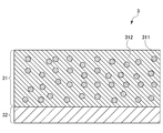
- FIG. 4 is a diagram showing a cross-sectional configuration example of the radiator 3 according to the present embodiment.
- the radiator 3 is composed of, for example, a polymer layer 31 and a metal reflective layer 32, as shown in FIG.
- the polymer layer 31 is configured by dispersing a plurality of dielectric particles 311 in a dispersion medium 312.
- the desired wavelength selectivity can be obtained by appropriately selecting the particle size and material of the dielectric particles 311 or the physical properties of the dispersion medium.
- the dispersion medium 312 is preferably composed of a material capable of transmitting infrared rays having a wavelength of 8 to 13 ⁇ m. This is to efficiently release heat energy from the window of the atmosphere into outer space.
- the dielectric particles 311 preferably consist of at least one selected from the group consisting of silicon dioxide, calcium carbonate, silicon carbide, zinc oxide, titanium dioxide, and alumina.
- the dispersion medium 312 preferably comprises at least one selected from the group consisting of 4-methyl-1-pentene polymer, 4-methyl-1-pentene copolymer, polyvinyl fluoride and polyethylene terephthalate.
- the dispersion medium 312 can be formed using TPX TM manufactured by Mitsui Chemicals, Inc.
- a MIM (metal-insulator-metal) structure and a cavity structure can also be used.
- FIG. 5 is an external perspective view showing an example of the radiator 3 according to the present embodiment.
- the efficiency of radiation changes depending on the shape of the radiator 3. That is, by providing the radiator 3 with an uneven structure, the surface area of the radiator 3 can be increased and the amount of heat energy released can be increased. However, it is also conceivable that the infrared rays radiated from itself may be reabsorbed by having the uneven structure. Therefore, it is preferable that the radiator 3 has a shape and a configuration so as to increase the surface area and reduce the amount of reabsorbing infrared rays emitted from the radiator 3.
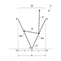
- the shape of the radiator 3 of the present embodiment is formed in a bellows shape in which mountain portions 35 and valley portions 33 are alternately and continuously arranged in a predetermined direction as shown in FIG. 6 to 9 are cross-sectional views of the valley 33 of one of the bellows structures.
- the facing surfaces 34a and 34b of the valley 33 are symmetrical with respect to the normal passing through the point O of the OH plane in FIG. 6, and both form an angle ⁇ with respect to the OH plane (0 ° ⁇ ⁇ 90 °). ).
- the horizontal distance between the tops R and R of the facing surfaces is 2L. In the present disclosure, this distance is also referred to as the width of the valley 33.
- FIG. 6 is a diagram showing the traveling direction of infrared rays emitted from a certain point on the radiator 3. Infrared rays are radiated from each point on the radiator 3. As shown in FIG. 6A, the infrared rays radiated from the surface 34a include a component A that advances toward the air as it is and a component B that advances toward the opposite surface 34b. When the wavelength selectivity of the facing surfaces 34a and 34b of the valley portion 33 of the radiator 3 is the same, the component B is absorbed by the opposing surfaces 34b.
- the ratio of the component absorbed on the opposite surface to the component radiated into the air changes depending on the angle ⁇ in FIG.
- this angle ⁇ becomes small, the ratio of the components absorbed decreases, and when the angle ⁇ becomes large, the ratio of absorbed components increases.
- the angle ⁇ is large, the surface area of the radiator increases, so that the total amount of infrared rays emitted increases.
- the cooling efficiency needs to be calculated by integrating the total amount of infrared rays and the ratio of the components radiated into the air.
- the total amount of infrared rays that contribute to cooling is specifically considered by a mathematical formula.
- the total amount P of infrared rays is represented by the product of the radiation amount p (T) per unit area, the area term L / cos ⁇ of the radiator 3, and the angle term which is an angle component radiated into the air, and is represented by FIG.
- the total amount of infrared rays is as shown in the following equation (1).
- P (T) indicates that the amount of infrared radiation is temperature-dependent
- L and ⁇ are defined as shown in FIG.
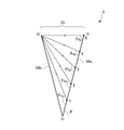
- the angles ⁇ ka and ⁇ kb shown in FIGS. 7A and 7B are the angles formed by the infrared angular component group emitted from a certain point on the surface 34a of the radiator 3 with the surface 34a of the radiator 3 in the air. Indicates the maximum angle that is not radiated to.
- the group of infrared angle components radiated from the infrared component indicates the maximum angle of the infrared component that is not radiated into the air among the angles formed by the surface 34a of the radiator 3.
- FIG. 8 shows a component radiating from the surface 34a to the surface 34b
- FIG. 9 shows a component reflected from the surface 34b and incident on the surface 34a.
- the points that divide the surface 34a into n are the points 1, 2, and. .. .. Assuming n, the larger n is, the more accurately the radiation from the surface 34a can be considered.
- the surface 34a is divided into five, and five points 1 to 5 are illustrated.
- the angular component whose angle with the surface 34a of the radiator 3 is larger than ⁇ k is radiated into the air and contributes to cooling.
- the angle term can be expressed by a mathematical formula as shown in equation (2).
- equation (2) the surface 34a of the radiator 3 is divided into n pieces, and the angles radiated into the air at each point are added to make n ⁇ ⁇ .
- the ratio of the components radiated into the air among the infrared rays radiated from each point of the radiator 3 can be expressed as an angle term.
- the calculation method of the term of the angle component is different depending on whether the wavelength selectivity between the left and right surfaces of the radiator 3 is the same or different.
- the wavelength selectivity between the left and right surfaces of the radiator 3 is the same, the component of the emitted infrared rays that is incident on the facing radiator 3 is absorbed, so only the component that is directly radiated into the air is the angular term.
- an angle larger than ⁇ ka shown in FIG. 7A may be considered.
- the component of the emitted infrared rays that is incident on the facing radiator 3 is reflected.
- the reflected component is divided into a component that recurses to the original radiator 3 and a component that is reflected into the air, but since the former is absorbed, only the latter is considered in the angle term. That is, the sum of the component directly radiated into the air from the original radiator 3 and the component reflected into the air by the opposing radiator 3 is considered as an angle term. At this time, an angle larger than ⁇ kb shown in FIG. 7B may be considered.
- FIG. 10 is a graph showing the inclination angle ⁇ dependence of the area term.
- FIG. 11 is a graph showing the inclination angle ⁇ dependence of the angle term.
- the proportion of infrared rays absorbed by the opposing surfaces of the radiator 3 increases as ⁇ increases in the entire range of 0 ° ⁇ ⁇ 90 °. , The angle term becomes smaller.
- the cooling device 1 of the present embodiment infrared rays having a specific wavelength can be radiated, and the cooling efficiency is improved by increasing the surface area due to the uneven structure of the radiator.
- the facing surfaces 34a and 34b of the valley 33 are formed symmetrically with respect to the normal passing through the point O of the OH plane in FIG. 6, but the facing surfaces 34a and 34b of the valley 33 are asymmetric. It may be formed, and the cooling efficiency is similarly improved.
- the cooling device 1 of the present embodiment includes a radiator 3 capable of selectively radiating an electromagnetic wave having a specific wavelength and having an uneven structure on the surface.
- the surface area of the radiator is larger than that of the radiator formed in a single plane, and radiative cooling can be performed efficiently.
- the uneven structure is a bellows structure in which peaks 35 and valleys 33 are alternately and continuously arranged in a predetermined direction, and the two surfaces 34a and 34b that form the valleys 33 and face each other have different wavelength selections. It is preferable to have sex. As a result, the electromagnetic waves radiated between the opposing surfaces can be reflected, so that radiative cooling can be performed efficiently.
- the uneven structure is also a bellows structure in which peaks 35 and valleys 33 are alternately and continuously arranged in a predetermined direction, and the two surfaces 34a and 34b that form the valleys 33 and face each other have the same wavelength. It has selectivity, and the size of the angle (for example, the angle ⁇ described later) formed by the two surfaces with respect to the surface extending in the predetermined direction is the same, and the size of the angle formed is 75 ° or more and 90 °. It may be less than. As a result, the surface area of the radiator is larger than that of the radiator formed on a single plane, and the cooling efficiency is improved even if the electromagnetic waves radiated between the opposing surfaces are absorbed. ..
- the wavelength of the electromagnetic wave radiated from at least one of the two surfaces 34a and 34b includes a part of the wavelength region where the transmittance of the atmosphere is larger than zero.
- the wavelengths of the electromagnetic waves radiated from the two surfaces 34a and 34b both include a part of the wavelength region where the transmittance of the atmosphere is larger than zero. This makes it possible to perform radiative cooling more efficiently.
- the radiator 3 includes a polymer layer 31 and a metal reflective layer 32 laminated with the polymer layer 31, and the polymer layer 31 is composed of a dispersion medium 312 and a plurality of dielectrics dispersed in the dispersion medium 312. It has the body particles 311 and the dielectric particles 311 preferably consist of at least one selected from the group consisting of silicon dioxide, calcium carbonate, silicon carbide, zinc oxide, titanium dioxide and alumina. As a result, good wavelength selectivity can be obtained.
- the dispersion medium 312 preferably comprises at least one selected from the group consisting of 4-methyl-1-pentene polymer, 4-methyl-1-pentene copolymer, polyvinyl fluoride and polyethylene terephthalate. As a result, even better wavelength selectivity can be obtained.
- the cooling device 1 is installed outdoors and the radiator 3 is installed so as to radiate above the horizontal toward outer space. As a result, electromagnetic waves are radiated toward outer space, so that radiative cooling can be performed efficiently.
- the cooling device 1 can be used as a building cooling system 10 by attaching it to the roof of the building 6. At that time, by installing the photovoltaic power generation panel 7 on the sunny south roof and the cooling device 1 on the vacant north roof, the roof space can be effectively used to generate power and radiative cooling at the same time. It can be carried out. Further, if the electric power generated by the panel 7 is used as a power source for the refrigerant circulation, cooling can be performed with higher efficiency.
- the radiator 3 has wavelength selectivity that allows it to pass through the atmosphere, and can directly exhaust heat to outer space. That is, the exhaust heat of cooling does not affect the vicinity of the place where the device is used. If the cooling device 1 is introduced in an urban area where buildings are overcrowded, it may lead to mitigation of the heat island phenomenon. Further, the cooling device 1 of the present embodiment may be used as a cold storage system.
- FIG. 13 is a diagram showing a radiator 103 according to the second embodiment of the present disclosure.
- the cooling device 101 according to the second embodiment of the present disclosure has a different shape of the radiator 3 as compared with the first embodiment.
- the radiator 103 according to the second embodiment is configured such that the bellows structure of the radiator 3 is alternately and continuously arranged with peaks and valleys in a direction orthogonal to the predetermined direction. That is, the shape is such that the quadrangular pyramids are lined up continuously. As a result, the surface area of the radiator 3 is increased, so that the cooling efficiency is further improved.
- the lower part of FIG. 13 shows a cross section of the radiator 103 on a plane passing through the line segments X 1 X 2 and perpendicular to the bottom surface of the quadrangular pyramid.
- FIG. 14 is a diagram showing the radiator 203 according to the third embodiment of the present disclosure.
- the cooling device 201 according to the third embodiment of the present disclosure is configured by arranging quadrangular pyramids instead of quadrangular pyramids in the radiator 103 according to the second embodiment. Also in this form, the surface area of the radiator is increased as compared with the case where the concave-convex structure is not provided, so that the cooling efficiency is improved.
- the lower part of FIG. 14 shows a cross section of the radiator 203 on a plane perpendicular to the upper surface and the bottom surface of the quadrangular pyramid through the line segments Y 1 and Y 2 . The same effect can be obtained even if the trapezoids are continuously arranged in the continuous direction of the bellows structure in the first embodiment.
- the embodiment of the present disclosure has been described above.
- the embodiments of the present disclosure are not limited to this, and improved / modified ones are also included in the present disclosure.
- the shape of the radiator may be changed, but the radiation efficiency may be improved by the increase in the surface area of the radiator and the reflection utilizing the difference in wavelength selectivity. For example, it is included in this disclosure.
- Cooling device 2 Containment part 3,103,203 Radiant 31 Polymer layer 311 Dielectric particle 312 Dispersion medium 32 Metal reflection layer 33 Valley 34a, b Opposite surface of valley 35 Mountain part 4 Heat exchange tube 5 Atmospheric window 6 Building 7 Photovoltaic panel 10 Cooling system
Landscapes
- Engineering & Computer Science (AREA)
- Physics & Mathematics (AREA)
- Architecture (AREA)
- Chemical & Material Sciences (AREA)
- Combustion & Propulsion (AREA)
- Mechanical Engineering (AREA)
- General Engineering & Computer Science (AREA)
- Acoustics & Sound (AREA)
- Life Sciences & Earth Sciences (AREA)
- Sustainable Development (AREA)
- Electromagnetism (AREA)
- Civil Engineering (AREA)
- Structural Engineering (AREA)
- Cooling Or The Like Of Electrical Apparatus (AREA)
- Shielding Devices Or Components To Electric Or Magnetic Fields (AREA)
- Building Environments (AREA)
- Devices For Blowing Cold Air, Devices For Blowing Warm Air, And Means For Preventing Water Condensation In Air Conditioning Units (AREA)
Abstract
特定波長の電磁波を選択的に放射可能であるとともに、表面に凹凸構造を有する放射体を備える、冷却装置である。前記凹凸構造は、山部と谷部が所定方向に交互に連続して配置された構造であることが好ましい。これにより、波長選択性を有する放射体を備える冷却装置において、冷却効率を向上させることが可能になる。
Description
本開示は、冷却装置に関する。
従来、放射を利用した冷暖房装置に関し、放射される赤外線の波長を制御し、人体等の被加熱物に吸収されやすい特定波長の赤外線を放射の主波長とするとともに、放射される赤外線の指向性を高め、被加熱物に向けて選択的に加熱を行うことで冷暖房の効率を向上させる技術が提案されている。
特許文献1には、熱交換パイプに接するように熱伝導シートを折り曲げて配置することで放射パネルへの接触面積を増大させて伝熱量を増やし、冷暖房の効率を高める技術が開示されている。
また、特許文献2には、地球上の大気が特定波長の赤外線を吸収せずに透過することや、粒子を混合したポリマー層に金属反射層を合わせたフィルムによって、波長選択的な放射冷却が可能であることが開示されている。
しかしながら、特許文献2に記載の折り曲げた構造を有する熱伝導体においては、熱伝導体から放射された赤外線が熱伝導体の他の箇所で吸収されるため、外部との伝熱量が小さくなり冷暖房効率が低減してしまう。
本開示は、上記に鑑みてなされたものであり、波長選択性を有する放射体を備える冷却装置において、冷却効率を向上させることを目的とする。
本開示は、特定波長の電磁波を選択的に放射可能であるとともに、表面に凹凸構造を有する放射体を備える、冷却装置を提供する。
以下、本開示の実施形態について説明するが、本開示はこれに限定されるものではない。
(第1実施形態)
図1は、本実施形態の冷却装置1を建物の屋根に設置した使用例を表す図である。図2は、本開示の第1実施形態に係る冷却装置1を示す図である。
図2に示すように、本実施形態に係る冷却装置1は、収容部2と、放射体3と、を有して構成される。本実施形態に係る冷却装置1は、例えば建物の冷房装置として用いられる。具体的には、例えば、図1に示すように建物の屋根等に設置されて上空へ向けて放射冷却を行う。
図1は、本実施形態の冷却装置1を建物の屋根に設置した使用例を表す図である。図2は、本開示の第1実施形態に係る冷却装置1を示す図である。
図2に示すように、本実施形態に係る冷却装置1は、収容部2と、放射体3と、を有して構成される。本実施形態に係る冷却装置1は、例えば建物の冷房装置として用いられる。具体的には、例えば、図1に示すように建物の屋根等に設置されて上空へ向けて放射冷却を行う。
収容部2は、放射体3を収容可能な構造を有する。収容部2の材質や形状については特に制限されないが、加熱される放射体3を収容するため、金属や耐熱性樹脂等、一定の耐熱性を有する材質により構成されることが好ましい。収容部2は、例えば、屋根、壁、天井等に埋設されて建物の一部であってもよいし、独立した筐体であってもよい。
放射体3は、熱源から受け取った熱エネルギーを、一定の波長領域を有する電磁波(本実施形態においては、赤外線)として放射する。このとき、放射された赤外線が大気に吸収されてしまうと冷却対象の周囲の気温を上昇させてしまうため、冷却効率が低下する。そのため、熱エネルギーが赤外線放射される場合には、大気に吸収されにくい波長で放射され、宇宙空間に放出されることが好ましい。
大気を透過しにくい波長で放射を行う場合、夏の日中等の高温多湿な時間帯には、放射熱が冷却装置周囲の空気に吸収され、高温の空気から装置に伝熱する結果、放射冷却の効果が感じられにくい。この点、大気に吸収されずに宇宙空間に向けて放射する場合には、空気からの伝熱量が少なくなり、放射冷却の効果をより高く感じることができる。
図3は、大気中に含まれる気体の赤外線透過率を示すグラフである。最下段は、大気の赤外線透過率を示すグラフである。
図3に示すように、大気中の赤外線の透過率は赤外線の波長によって異なり、例えば8~13μmの波長の赤外線は大気には吸収されにくく、大部分が透過される。このような大気を透過可能な波長域は、大気の窓と呼ばれる。したがって、8~13μmの波長の赤外線を水平よりも上方に向けて放射すれば、熱エネルギーを効率よく宇宙空間に放出することができる。
図3に示すように、大気中の赤外線の透過率は赤外線の波長によって異なり、例えば8~13μmの波長の赤外線は大気には吸収されにくく、大部分が透過される。このような大気を透過可能な波長域は、大気の窓と呼ばれる。したがって、8~13μmの波長の赤外線を水平よりも上方に向けて放射すれば、熱エネルギーを効率よく宇宙空間に放出することができる。
熱エネルギーを放出された熱源は冷却されて、温度が低下する。放射体3に熱を供給する熱源として例えば水や気体等の冷媒を用いれば、放射体3の放射冷却により低温となった冷媒を建物の各部屋を通る熱交換チューブに通し、部屋を冷却した後、再び高温となった冷媒を放射体3によって冷却することで、建物の冷房システムとして利用可能である。
図4は、本実施形態に係る放射体3の断面構成例を示す図である。
放射体3は、例えば図4に示すように、ポリマー層31と、金属反射層32とからなる。ポリマー層31は、複数の誘電体粒子311を分散媒312中に分散させて構成される。誘電体粒子311の粒径や材質、あるいは分散媒の物性を適当に選択することで、所望の波長選択性が得られる。
分散媒312は、8~13μmの波長の赤外線を透過させうる材料で構成することが好ましい。大気の窓から熱エネルギーを効率よく宇宙空間に放出させるためである。
放射体3は、例えば図4に示すように、ポリマー層31と、金属反射層32とからなる。ポリマー層31は、複数の誘電体粒子311を分散媒312中に分散させて構成される。誘電体粒子311の粒径や材質、あるいは分散媒の物性を適当に選択することで、所望の波長選択性が得られる。
分散媒312は、8~13μmの波長の赤外線を透過させうる材料で構成することが好ましい。大気の窓から熱エネルギーを効率よく宇宙空間に放出させるためである。
例えば、誘電体粒子311は、二酸化ケイ素、炭酸カルシウム、炭化ケイ素、酸化亜鉛、二酸化チタン、アルミナからなる群より選択される少なくとも1種からなることが好ましい。また、分散媒312は、4-メチル-1-ペンテンポリマー、4-メチル-1-ペンテンコポリマー、ポリフッ化ビニルおよびポリエチレンテレフタレートからなる群より選択される少なくとも1種からなることが好ましい。例えば、三井化学社製のTPXTMを用いて分散媒312を形成することができる。
波長選択性を有する構造としては、例えば、本実施形態の放射体の他、MIM(metal-insulator-metal)構造、キャビティ構造も利用することができる。
波長選択性を有する構造としては、例えば、本実施形態の放射体の他、MIM(metal-insulator-metal)構造、キャビティ構造も利用することができる。
図5は、本実施形態に係る放射体3の一例を示す外観斜視図である。
放射体3の形状により、放射の効率が変化する。すなわち、放射体3に凹凸構造を設けることで、放射体3の表面積を増大させて、放出する熱エネルギーの量を増加させることができる。ただし、凹凸構造を有することによって、自身から放射された赤外線を再吸収してしまうことも考えられる。そのため放射体3は、表面積を増大させつつ、自身から放射された赤外線を再吸収する量が少なくなるような形状および構成であることが好ましい。
放射体3の形状により、放射の効率が変化する。すなわち、放射体3に凹凸構造を設けることで、放射体3の表面積を増大させて、放出する熱エネルギーの量を増加させることができる。ただし、凹凸構造を有することによって、自身から放射された赤外線を再吸収してしまうことも考えられる。そのため放射体3は、表面積を増大させつつ、自身から放射された赤外線を再吸収する量が少なくなるような形状および構成であることが好ましい。
具体的には、本実施形態の放射体3の形状は、図5に示すような山部35と谷部33が所定方向に交互に連続して配置された蛇腹状に形成される。また図6~図9は、蛇腹構造のうちの一の谷部33について断面視したものである。谷部33の向かい合う面34a、34bは、図6におけるOH平面の点Oを通る法線に関して互いに対称に構成され、OH平面に対してともに角θをなしている(0°<θ<90°)。向かい合う面34a、34bの一つの頂部Rから底部Oに至るOR面のOH平面への正射影の長さをLとすると、向かい合う面の頂部R,R間の水平方向の距離は2Lとなる。本開示においては、この距離を谷部33の幅とも称する。
図6は、放射体3上のある点から放射される赤外線の進む方向を示す図である。
赤外線は放射体3上の各点から放射状に放射される。図6Aに示すように、面34aから放射される赤外線は、そのまま空気中に向けて進む成分Aと、対向する面34bに向けて進む成分Bが存在する。放射体3の谷部33の向かい合う面34a、34bの波長選択性が同じ場合には、成分Bは対向する面34bに吸収される。
赤外線は放射体3上の各点から放射状に放射される。図6Aに示すように、面34aから放射される赤外線は、そのまま空気中に向けて進む成分Aと、対向する面34bに向けて進む成分Bが存在する。放射体3の谷部33の向かい合う面34a、34bの波長選択性が同じ場合には、成分Bは対向する面34bに吸収される。
放射体3の谷部33の向かい合う面34a、34bの波長選択性が異なる場合には、図6Bに示すように、反射してさらに空気中に進む(B1)か、もしくは対向する右側の面34aに向けて進む(B2)。放射体3の左右の面の波長選択性が同じ場合と比較して、成分B1の分だけ空気中に放射される赤外線量が多くなるため、冷却効率が向上する。成分B2は、右側の面34aに吸収される。
なお、空気中に放射される成分に対する、対向する面に吸収される成分の比率は、図6中の角度θによって変化する。この角度θが小さくなると吸収される成分の比率は減少し、角度θが大きくなれば吸収される比率は増加する。ただし、角度θが大きければ放射体の表面積が増大するため、放射する赤外線の総量が増加する。冷却効率は赤外線の総量と空気中に放射される成分の比率を総合して算出される必要がある。
ここで、冷却に寄与する赤外線の総量について具体的に数式で考える。赤外線の総量Pは、単位面積あたりの放射量p(T)と、放射体3の面積項L/cosθと、空気中に放射される角度成分である角度項との積で表され、図6の平面内で考えると赤外線総量は下記式(1)のようになる。なお、P(T)は赤外線の放射量が温度に依存することを示し、Lおよびθは図6のように定義されるものとする。

図7Aおよび図7B中に示す角度θka,θkbは、放射体3の面34a上のある点から放射される赤外線の角度成分群が放射体3の面34aとなす角度のうち、空気中に放射されない最大の角度を示す。
同様に、図8および図9中に示す角度θ1α,θ2α,...(α=a,b)は、放射体3の面34a上の点1,2,...から放射される赤外線の角度成分群が、放射体3の面34aとなす角度のうち、空気中に放射されない赤外線成分の最大の角度を示す。このうち、図8は面34aから面34bに対して放射する成分を示し、図9は面34bから反射して面34aに入射する成分を示す。ここで、面34aをn分割する点を点1,2,...nとすると、nを大きくするほど面34aからの放射を精度よく考慮できる。図8および9では、面34aを5分割し、点1から5までの5点について図示している。
同様に、図8および図9中に示す角度θ1α,θ2α,...(α=a,b)は、放射体3の面34a上の点1,2,...から放射される赤外線の角度成分群が、放射体3の面34aとなす角度のうち、空気中に放射されない赤外線成分の最大の角度を示す。このうち、図8は面34aから面34bに対して放射する成分を示し、図9は面34bから反射して面34aに入射する成分を示す。ここで、面34aをn分割する点を点1,2,...nとすると、nを大きくするほど面34aからの放射を精度よく考慮できる。図8および9では、面34aを5分割し、点1から5までの5点について図示している。
放射体3の面34a上のある点から放射される赤外線の角度成分群のうち、放射体3の面34aとなす角度がθkよりも大きい角度成分が、空気中に放射されて冷却に寄与する。すなわち、上記式(1)の角度項の意味するところは、(θkよりも大きい角度成分)/(放射する全角度範囲=180°)である。
角度項を数式で表すと、式(2)のようになる。式(2)は、放射体3の面34aをn個に分割し、各点についての空気中に放射される角度を足し合わせ、n→∞としたものである。これにより、放射体3の各点から放射状に放射される赤外線のうち、空気中に放射される成分の割合を角度項として表せる。

なお、放射体3の左右の面同士の波長選択性が同じ場合と異なる場合について、角度成分の項の算出方法が異なる。放射体3の左右の面同士の波長選択性が同じ場合には、放射された赤外線のうち向かい合う放射体3に入射する成分は吸収されるため、空気中に直接放射される成分のみを角度項として考慮する。すなわち、図7Aに示すθkaよりも大きい角度を考慮すればよい。
放射体3の左右の面同士の波長選択性が異なる場合には、放射された赤外線のうち、向かい合う放射体3に入射する成分は反射される。反射された成分は、元の放射体3に再帰する成分と、空気中へ反射される成分に分けられるが、前者は吸収されるため、後者のみを角度項に考慮する。すなわち、元の放射体3から空気中に直接放射される成分と、向かい合う放射体3で空気中へ反射される成分との和を角度項として考慮する。このとき、図7Bに示すθkbよりも大きい角度を考慮すればよい。
図10は、面積項の傾斜角θ依存性を表すグラフである。
上述したように、図6の平面内で考えれば、放射体3の面積項はL/cosθで表される。よってθの増加に伴って、面積項は1/cosθ倍となるから、0°<θ<90°において図10に示すように増加していく。またθ=0のときの面積項を1とする。
上述したように、図6の平面内で考えれば、放射体3の面積項はL/cosθで表される。よってθの増加に伴って、面積項は1/cosθ倍となるから、0°<θ<90°において図10に示すように増加していく。またθ=0のときの面積項を1とする。
図11は、角度項の傾斜角θ依存性を表すグラフである。
θ=0°、すなわち放射体3が凹凸構造を有しない平面構造である場合、放射体3から放射された赤外線はすべて空気中に放出されることとなる。したがって、θk=0°であり、角度項は180°/180°=1である。
θ=0°、すなわち放射体3が凹凸構造を有しない平面構造である場合、放射体3から放射された赤外線はすべて空気中に放出されることとなる。したがって、θk=0°であり、角度項は180°/180°=1である。
放射体3の左右の面同士の波長選択性が同じ場合、0°<θ<90°の全範囲において、θの増加に伴って向かい合う放射体3の面に吸収される赤外線の割合が増加し、角度項は小さくなる。
放射体3の左右の面同士の波長選択性が異なる場合、0°<θ≦45°のときには、向かい合う放射体3で反射した赤外線は、すべて空気中に反射されることとなるから、放射体3から放射された赤外線はすべて空気中に放出されることとなる。したがって、θk=0°であり、このθの範囲において角度項は常に1となる。45°<θ<90°の時には、放射体3の左右の面同士の波長選択性が同じ場合と同様に、θの増加に伴って角度項は小さくなる。
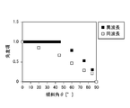
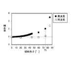
図12は、赤外線の放射量の傾斜角θ依存性を表すグラフである。
これは、式(1)で表される赤外線総量Pを計算したものであり、図10および11に示す面積項および角度項を掛け合わせたものに比例する。角度項はn=5として幾何光学の原理に基づき、入射角と反射角が等しくなる点を算出した。また、θ=0°、すなわち放射体3が凹凸構造を有しない平面構造である場合の放射量を1とする。
これは、式(1)で表される赤外線総量Pを計算したものであり、図10および11に示す面積項および角度項を掛け合わせたものに比例する。角度項はn=5として幾何光学の原理に基づき、入射角と反射角が等しくなる点を算出した。また、θ=0°、すなわち放射体3が凹凸構造を有しない平面構造である場合の放射量を1とする。
放射体3の左右の面同士の波長選択性が同じ場合、75°≦θ<90°の範囲において、θ=0°のときと比較して放射量が増加していることがわかる。さらに放射体3の左右の面同士の波長選択性が異なる場合には、0°<θ<90°の全範囲でθの増加に伴って放射量が増加する。θが大きくなるほど放射量は大きく増加し、特に75°≦θ<90°の範囲においては、放射体3が平面構造である場合と比べて2倍以上の放射量となり、高効率な放射が可能である。
以上、本実施形態の冷却装置1によれば、特定の波長の赤外線を放射できるとともに、放射体の凹凸構造によって表面積を増大させることで冷却効率が向上する。なお、本実施形態では谷部33の向かい合う面34a、34bが図6におけるOH平面の点Oを通る法線に関して互いに対称に形成されているが、谷部33の向かい合う面34a、34bが非対称に形成されていてもよく、同様に冷却効率が向上する。
本実施形態の冷却装置1は、特定波長の電磁波を選択的に放射可能であるとともに、表面に凹凸構造を有する放射体3を備える。これにより、単一平面で形成される放射体と比較して放射体の表面積が大きくなり、放射冷却を効率的に行うことが可能になる。
前記凹凸構造は、山部35と谷部33が所定方向に交互に連続して配置された蛇腹構造であり、谷部33を構成するとともに対向する2つの面34a,34bは、それぞれ異なる波長選択性を有することが好ましい。これにより、対向する面同士で放射された電磁波を反射可能であるため、放射冷却を効率的に行うことが可能になる。
前記凹凸構造は若しくは、山部35と谷部33が所定方向に交互に連続して配置された蛇腹構造であり、谷部33を構成するとともに対向する2つの面34a,34bは、同一の波長選択性を有し、前記2つの面が前記所定方向に延びる面に対してなす角(例えば、後述の角θ)の大きさは同一であり、前記なす角の大きさは75°以上90°未満であってもよい。これにより、単一平面で形成される放射体と比較して放射体の表面積が大きくなり、対向する面同士での放射された電磁波が吸収されることを加味しても、冷却効率が向上する。
2つの面34a,34bのうち少なくとも一方の面から放射される電磁波の波長は、大気の透過率がゼロより大きい波長領域を一部含む。これにより、放射された電磁波が冷却対象の周囲の空気に吸収されることなく宇宙空間へ放出されるため、放射冷却を効率的に行うことが可能になる。
2つの面34a,34bから放射される電磁波の波長は、ともに大気の透過率がゼロより大きい波長領域を一部含むことが好ましい。これにより、さらに放射冷却を効率的に行うことが可能になる。
放射体3は、ポリマー層31と、ポリマー層31と積層される金属反射層32と、を有して構成され、ポリマー層31は、分散媒312と、分散媒312に分散される複数の誘電体粒子311と、を有し、誘電体粒子311は、二酸化ケイ素、炭酸カルシウム、炭化ケイ素、酸化亜鉛、二酸化チタンおよびアルミナからなる群より選択される少なくとも1種からなることが好ましい。これにより、良好な波長選択性が得られる。
分散媒312は、4-メチル-1-ペンテンポリマー、4-メチル-1-ペンテンコポリマー、ポリフッ化ビニルおよびポリエチレンテレフタレートからなる群より選択される少なくとも1種からなることが好ましい。これにより、さらに良好な波長選択性が得られる。
冷却装置1は、屋外に設置されるとともに、放射体3は、宇宙空間に向けて水平よりも上方に放射するよう設置されることが好ましい。これにより、電磁波が宇宙空間へ向けて放射されるため、放射冷却を効率的に行うことが可能になる。
以上、本開示の第1実施形態について説明した。
本開示の冷却装置1の利用の形態例として、図1に示すように、冷却装置1を建物6の屋根に取り付けることによって建物の冷房システム10として用いることができる。その際、日当たりのよい南面の屋根に太陽光発電パネル7を設置し、空いた北面の屋根に冷却装置1を設置することで、屋根のスペースを有効に利用して、発電と放射冷却を同時に行うことができる。また、パネル7によって発電した電力を冷媒循環の動力源として使用すれば、より高効率に冷却を行うことができる。
また、放射体3は大気を透過する波長選択性を有しており、熱を宇宙空間に直接排熱することが可能である。すなわち、冷却の排熱が装置使用箇所近辺に影響することがない。
冷却装置1を建物過密である都市部で導入すれば、ヒートアイランド現象の緩和にも繋がる可能性がある。さらには、本実施形態の冷却装置1を用いて、蓄冷システムとしてもよい。
冷却装置1を建物過密である都市部で導入すれば、ヒートアイランド現象の緩和にも繋がる可能性がある。さらには、本実施形態の冷却装置1を用いて、蓄冷システムとしてもよい。
次に、本開示の他の実施形態の冷却装置について説明する。
(第2実施形態)
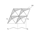
図13は、本開示の第2実施形態に係る放射体103を表す図である。
本開示の第2実施形態に係る冷却装置101は、第1実施形態と比較して、放射体3の形状が異なる。第2実施形態に係る放射体103は、放射体3の蛇腹構造が、前記所定方向に直交する方向にも山部と谷部が交互に連続して配置されて構成される。すなわち、四角錐が連続して並ぶ形状となる。これにより、放射体3の表面積が増大するため、冷却効率がさらに向上する。また図13下部には、線分X1X2を通り四角錐の底面に垂直な面における、放射体103の断面を示している。
図13は、本開示の第2実施形態に係る放射体103を表す図である。
本開示の第2実施形態に係る冷却装置101は、第1実施形態と比較して、放射体3の形状が異なる。第2実施形態に係る放射体103は、放射体3の蛇腹構造が、前記所定方向に直交する方向にも山部と谷部が交互に連続して配置されて構成される。すなわち、四角錐が連続して並ぶ形状となる。これにより、放射体3の表面積が増大するため、冷却効率がさらに向上する。また図13下部には、線分X1X2を通り四角錐の底面に垂直な面における、放射体103の断面を示している。
(第3実施形態)
図14は、本開示の第3実施形態に係る放射体203を表す図である。
本開示の第3実施形態に係る冷却装置201は、第2実施形態に係る放射体103において、四角錐でなく四角錐台が並んで構成される。この形態においても、凹凸構造を有しない場合と比較して放射体の表面積が増大するため、冷却効率が向上する。また図14下部には、線分Y1Y2を通り四角錐台の上面および底面に垂直な面における、放射体203の断面を示している。
なお、第1実施形態において蛇腹構造の連続する方向に台形が連続して並ぶような構成としても、同様な効果が得られる。
図14は、本開示の第3実施形態に係る放射体203を表す図である。
本開示の第3実施形態に係る冷却装置201は、第2実施形態に係る放射体103において、四角錐でなく四角錐台が並んで構成される。この形態においても、凹凸構造を有しない場合と比較して放射体の表面積が増大するため、冷却効率が向上する。また図14下部には、線分Y1Y2を通り四角錐台の上面および底面に垂直な面における、放射体203の断面を示している。
なお、第1実施形態において蛇腹構造の連続する方向に台形が連続して並ぶような構成としても、同様な効果が得られる。
以上、本開示の実施形態について説明した。本開示の実施形態はこれに限定されるものではなく、改良・変形したものも本開示に含まれる。例えば、第2および第3実施形態以外にも放射体の形状を変更したものが考えられるが、放射体の表面積の増加および波長選択性の違いを利用した反射によって放射効率が向上するものであれば、本開示に含まれる。
1,101,201 冷却装置
2 収容部
3,103,203 放射体
31 ポリマー層
311 誘電体粒子
312 分散媒
32 金属反射層
33 谷部
34a,b 谷部の向かい合う面
35 山部
4 熱交換チューブ
5 大気の窓
6 建物
7 太陽光発電パネル
10 冷却システム
2 収容部
3,103,203 放射体
31 ポリマー層
311 誘電体粒子
312 分散媒
32 金属反射層
33 谷部
34a,b 谷部の向かい合う面
35 山部
4 熱交換チューブ
5 大気の窓
6 建物
7 太陽光発電パネル
10 冷却システム
Claims (8)
- 特定波長の電磁波を選択的に放射可能であるとともに、表面に凹凸構造を有する放射体を備える、冷却装置。
- 前記凹凸構造は、山部と谷部が所定方向に交互に連続して配置された構造であり、
前記谷部を構成するとともに対向する2つの面は、それぞれ異なる波長選択性を有する、請求項1に記載の冷却装置。 - 前記凹凸構造は、山部と谷部が所定方向に交互に連続して配置された構造であり、
前記谷部を構成するとともに対向する2つの面は、同一の波長選択性を有し、
前記2つの面が前記所定方向に延びる面に対してなす角の大きさは同一であり、前記なす角の大きさは75°以上90°未満である、請求項1に記載の冷却装置。 - 前記2つの面のうち少なくとも一方の面から放射される電磁波の波長は、大気の透過率がゼロより大きい波長領域を一部含む、請求項2または3に記載の冷却装置。
- 前記2つの面から放射される電磁波の波長は、ともに大気の透過率がゼロより大きい波長領域を一部含む、請求項2~4のいずれかに記載の冷却装置。
- 前記放射体は、ポリマー層と、前記ポリマー層に積層される金属反射層と、を有して構成され、
前記ポリマー層は、分散媒と、前記分散媒に分散される複数の誘電体粒子と、を有し、
前記誘電体粒子は、二酸化ケイ素、炭酸カルシウム、炭化ケイ素、酸化亜鉛、二酸化チタンおよびアルミナからなる群より選択される少なくとも1種からなる、請求項1~5のいずれかに記載の冷却装置。 - 前記分散媒は、4-メチル-1-ペンテンポリマー、4-メチル-1-ペンテンコポリマー、ポリフッ化ビニルおよびポリエチレンテレフタレートからなる群より選択される少なくとも1種からなる、請求項6に記載の冷却装置。
- 屋外に設置されるとともに、
前記放射体は、宇宙空間に向けて水平よりも上方に放射するよう設置される、請求項1~7のいずれかに記載の冷却装置。
Applications Claiming Priority (2)
| Application Number | Priority Date | Filing Date | Title |
|---|---|---|---|
| JP2019-109723 | 2019-06-12 | ||
| JP2019109723A JP6733010B1 (ja) | 2019-06-12 | 2019-06-12 | 冷却装置 |
Publications (1)
| Publication Number | Publication Date |
|---|---|
| WO2020250536A1 true WO2020250536A1 (ja) | 2020-12-17 |
Family
ID=71738628
Family Applications (1)
| Application Number | Title | Priority Date | Filing Date |
|---|---|---|---|
| PCT/JP2020/012374 Ceased WO2020250536A1 (ja) | 2019-06-12 | 2020-03-19 | 冷却装置 |
Country Status (2)
| Country | Link |
|---|---|
| JP (1) | JP6733010B1 (ja) |
| WO (1) | WO2020250536A1 (ja) |
Cited By (2)
| Publication number | Priority date | Publication date | Assignee | Title |
|---|---|---|---|---|
| JP2022146658A (ja) * | 2021-03-22 | 2022-10-05 | 大阪瓦斯株式会社 | 放射冷却式遮光装置 |
| BE1030564B1 (nl) * | 2022-05-25 | 2024-01-03 | Patrick Brants | Klimaatreguleringssysteem voor een gebouw |
Families Citing this family (1)
| Publication number | Priority date | Publication date | Assignee | Title |
|---|---|---|---|---|
| KR102810554B1 (ko) * | 2022-11-16 | 2025-05-23 | 주식회사 휴비스 | 도전성 폴리에스테르 복합섬유 및 그의 제조방법 |
Citations (3)
| Publication number | Priority date | Publication date | Assignee | Title |
|---|---|---|---|---|
| JP2002090080A (ja) * | 2000-09-12 | 2002-03-27 | Takeo Saito | マイクロ複合放物面集光(cpc)型放射冷却器 |
| WO2017151514A1 (en) * | 2016-02-29 | 2017-09-08 | The Regents Of The University Of Colorado, A Body Corporate | Radiative cooling structures and systems |
| JP2018526599A (ja) * | 2015-06-18 | 2018-09-13 | ザ トラスティーズ オブ コロンビア ユニヴァーシティ イン ザ シティ オブ ニューヨーク | 放射冷却および加熱用のシステムならびに方法 |
Family Cites Families (5)
| Publication number | Priority date | Publication date | Assignee | Title |
|---|---|---|---|---|
| AU2003233699A1 (en) * | 2002-05-28 | 2003-12-12 | Gordon Latos | Radiant heat pump device and method |
| JP2005047486A (ja) * | 2003-07-16 | 2005-02-24 | Nissan Motor Co Ltd | 内装吸放熱構造 |
| JP2012122648A (ja) * | 2010-12-07 | 2012-06-28 | Ishinoyu Co Ltd | 室内環境調整システム |
| JP2016188715A (ja) * | 2015-03-30 | 2016-11-04 | イムラ・ジャパン株式会社 | 放射冷却装置および冷却光利用システム |
| JP2020053285A (ja) * | 2018-09-27 | 2020-04-02 | 株式会社Lixil | 輻射ヒーター及び輻射ヒーターシステム |
-
2019
- 2019-06-12 JP JP2019109723A patent/JP6733010B1/ja not_active Expired - Fee Related
-
2020
- 2020-03-19 WO PCT/JP2020/012374 patent/WO2020250536A1/ja not_active Ceased
Patent Citations (3)
| Publication number | Priority date | Publication date | Assignee | Title |
|---|---|---|---|---|
| JP2002090080A (ja) * | 2000-09-12 | 2002-03-27 | Takeo Saito | マイクロ複合放物面集光(cpc)型放射冷却器 |
| JP2018526599A (ja) * | 2015-06-18 | 2018-09-13 | ザ トラスティーズ オブ コロンビア ユニヴァーシティ イン ザ シティ オブ ニューヨーク | 放射冷却および加熱用のシステムならびに方法 |
| WO2017151514A1 (en) * | 2016-02-29 | 2017-09-08 | The Regents Of The University Of Colorado, A Body Corporate | Radiative cooling structures and systems |
Cited By (3)
| Publication number | Priority date | Publication date | Assignee | Title |
|---|---|---|---|---|
| JP2022146658A (ja) * | 2021-03-22 | 2022-10-05 | 大阪瓦斯株式会社 | 放射冷却式遮光装置 |
| JP7474216B2 (ja) | 2021-03-22 | 2024-04-24 | 大阪瓦斯株式会社 | 放射冷却式遮光装置 |
| BE1030564B1 (nl) * | 2022-05-25 | 2024-01-03 | Patrick Brants | Klimaatreguleringssysteem voor een gebouw |
Also Published As
| Publication number | Publication date |
|---|---|
| JP2020201014A (ja) | 2020-12-17 |
| JP6733010B1 (ja) | 2020-07-29 |
Similar Documents
| Publication | Publication Date | Title |
|---|---|---|
| US11408689B2 (en) | Structures for radiative cooling | |
| US12061056B2 (en) | Radiative cooling with solar spectrum reflection | |
| WO2020250536A1 (ja) | 冷却装置 | |
| CA1251253A (en) | High-efficiency task heater | |
| EP2313946B3 (en) | Radome comprising an internal cooling system | |
| CN106767168A (zh) | 一种选择性辐射红外隐身结构 | |
| JP2020201031A (ja) | 冷却装置 | |
| US11162712B2 (en) | Solar light utilization apparatus and solar light utilization system | |
| US4716882A (en) | Solar heat collector | |
| JP2020193799A (ja) | 建築物用冷却装置および建築物用冷却システム | |
| KR102560227B1 (ko) | 냉온열 복합 생산 유닛 | |
| US20220307730A1 (en) | Devices and methods for concentrated radiative cooling | |
| JP2022094012A (ja) | 集熱器 | |
| Jeon et al. | Ideal spectral emissivity design for extreme radiative cooling | |
| CN115468212A (zh) | 一种基于高温热源定向辐射的追踪人体采暖设备 | |
| KR101859154B1 (ko) | 방사판을 포함하는 원적외선 난방기 | |
| US20210190383A1 (en) | Selective surfaces for radiant heat transfer | |
| JPS6222369B2 (ja) | ||
| KR20220091269A (ko) | 입사 및 방사 각도 제어 기반의 복사냉각 디바이스 | |
| JPH0139198B2 (ja) | ||
| JP2022541892A (ja) | 熱移送装置 | |
| JP2009222264A (ja) | 熱線トランス | |
| JPS5833463B2 (ja) | シユウネツソウチ | |
| JP2001194011A (ja) | 3次元複合放物面集光(cpc)型集熱器 | |
| JPS5946789A (ja) | ヒ−タ |
Legal Events
| Date | Code | Title | Description |
|---|---|---|---|
| 121 | Ep: the epo has been informed by wipo that ep was designated in this application |
Ref document number: 20821658 Country of ref document: EP Kind code of ref document: A1 |
|
| NENP | Non-entry into the national phase |
Ref country code: DE |
|
| 122 | Ep: pct application non-entry in european phase |
Ref document number: 20821658 Country of ref document: EP Kind code of ref document: A1 |