WO2020250352A1 - タッチパネル型情報端末装置およびその情報入力処理方法 - Google Patents
タッチパネル型情報端末装置およびその情報入力処理方法 Download PDFInfo
- Publication number
- WO2020250352A1 WO2020250352A1 PCT/JP2019/023351 JP2019023351W WO2020250352A1 WO 2020250352 A1 WO2020250352 A1 WO 2020250352A1 JP 2019023351 W JP2019023351 W JP 2019023351W WO 2020250352 A1 WO2020250352 A1 WO 2020250352A1
- Authority
- WO
- WIPO (PCT)
- Prior art keywords
- input
- input device
- touch
- touch operation
- input devices
- Prior art date
- Legal status (The legal status is an assumption and is not a legal conclusion. Google has not performed a legal analysis and makes no representation as to the accuracy of the status listed.)
- Ceased
Links
Images







Classifications
-
- G—PHYSICS
- G06—COMPUTING OR CALCULATING; COUNTING
- G06F—ELECTRIC DIGITAL DATA PROCESSING
- G06F3/00—Input arrangements for transferring data to be processed into a form capable of being handled by the computer; Output arrangements for transferring data from processing unit to output unit, e.g. interface arrangements
- G06F3/01—Input arrangements or combined input and output arrangements for interaction between user and computer
- G06F3/03—Arrangements for converting the position or the displacement of a member into a coded form
- G06F3/041—Digitisers, e.g. for touch screens or touch pads, characterised by the transducing means
- G06F3/0416—Control or interface arrangements specially adapted for digitisers
- G06F3/04166—Details of scanning methods, e.g. sampling time, grouping of sub areas or time sharing with display driving
-
- G—PHYSICS
- G06—COMPUTING OR CALCULATING; COUNTING
- G06F—ELECTRIC DIGITAL DATA PROCESSING
- G06F3/00—Input arrangements for transferring data to be processed into a form capable of being handled by the computer; Output arrangements for transferring data from processing unit to output unit, e.g. interface arrangements
- G06F3/01—Input arrangements or combined input and output arrangements for interaction between user and computer
- G06F3/03—Arrangements for converting the position or the displacement of a member into a coded form
- G06F3/041—Digitisers, e.g. for touch screens or touch pads, characterised by the transducing means
-
- G—PHYSICS
- G06—COMPUTING OR CALCULATING; COUNTING
- G06F—ELECTRIC DIGITAL DATA PROCESSING
- G06F3/00—Input arrangements for transferring data to be processed into a form capable of being handled by the computer; Output arrangements for transferring data from processing unit to output unit, e.g. interface arrangements
- G06F3/01—Input arrangements or combined input and output arrangements for interaction between user and computer
- G06F3/03—Arrangements for converting the position or the displacement of a member into a coded form
- G06F3/041—Digitisers, e.g. for touch screens or touch pads, characterised by the transducing means
- G06F3/0412—Digitisers structurally integrated in a display
-
- G—PHYSICS
- G06—COMPUTING OR CALCULATING; COUNTING
- G06F—ELECTRIC DIGITAL DATA PROCESSING
- G06F3/00—Input arrangements for transferring data to be processed into a form capable of being handled by the computer; Output arrangements for transferring data from processing unit to output unit, e.g. interface arrangements
- G06F3/01—Input arrangements or combined input and output arrangements for interaction between user and computer
- G06F3/048—Interaction techniques based on graphical user interfaces [GUI]
- G06F3/0487—Interaction techniques based on graphical user interfaces [GUI] using specific features provided by the input device, e.g. functions controlled by the rotation of a mouse with dual sensing arrangements, or of the nature of the input device, e.g. tap gestures based on pressure sensed by a digitiser
- G06F3/0488—Interaction techniques based on graphical user interfaces [GUI] using specific features provided by the input device, e.g. functions controlled by the rotation of a mouse with dual sensing arrangements, or of the nature of the input device, e.g. tap gestures based on pressure sensed by a digitiser using a touch-screen or digitiser, e.g. input of commands through traced gestures
-
- G—PHYSICS
- G06—COMPUTING OR CALCULATING; COUNTING
- G06F—ELECTRIC DIGITAL DATA PROCESSING
- G06F2203/00—Indexing scheme relating to G06F3/00 - G06F3/048
- G06F2203/041—Indexing scheme relating to G06F3/041 - G06F3/045
- G06F2203/04104—Multi-touch detection in digitiser, i.e. details about the simultaneous detection of a plurality of touching locations, e.g. multiple fingers or pen and finger
-
- G—PHYSICS
- G06—COMPUTING OR CALCULATING; COUNTING
- G06F—ELECTRIC DIGITAL DATA PROCESSING
- G06F2203/00—Indexing scheme relating to G06F3/00 - G06F3/048
- G06F2203/048—Indexing scheme relating to G06F3/048
- G06F2203/04808—Several contacts: gestures triggering a specific function, e.g. scrolling, zooming, right-click, when the user establishes several contacts with the surface simultaneously; e.g. using several fingers or a combination of fingers and pen
Definitions
- One aspect of the present invention relates to a touch panel type information terminal device provided with a touch panel type input interface and an information input processing method executed by this device.
- Information terminal devices having a touch panel with an input sheet arranged on the display screen have become widespread.
- the operation target can be specified by directly touching the display screen with a finger, so that an intuitive operation is possible.
- an external input device such as a mouse or a touch pad is not required, there is an advantage that a device shape having excellent portability can be realized.
- link destination information such as a software button (icon) or Uniform Resource Locator (URL) is displayed on the display screen, and the input area on the input sheet corresponding to the display area is tapped with a fingertip or the like. Described is a device that recognizes the software button and link destination information based on the tapped position coordinates and executes a predetermined process.
- icon software button
- URL Uniform Resource Locator
- the conventional touch panel type information terminal device has a structure in which an input sheet is arranged on one surface of the display screen, the input area by touch operation is limited to the above single input sheet, and software that can display at one time.
- the number of buttons (icons) is limited.
- one type of processing is assigned to one icon, so the types of processing that can be specified are also limited by the size of the input area. In order to increase the input area, it is necessary to increase the size of the terminal device or reduce the size of the icon, which leads to an increase in the size of the terminal device or a decrease in operability.
- the present invention has been made by paying attention to the above circumstances, and one aspect thereof is to provide a technique capable of designating a large number of processes without increasing the size of the terminal device and reducing the operability. It is a thing.
- a first aspect of the present invention is a display device having a first surface and a second surface on the back side of the first surface, and a display device arranged on the first surface of the display device and responding to a touch operation.
- a first input device that outputs a detection signal corresponding to the touch position, and a second input that is arranged on the second surface of the display device and outputs a detection signal corresponding to the touch position in response to a touch operation. It includes a device, a display device, and a terminal device main body connected to the first and second input devices.
- the terminal device main body includes a hardware processor and a memory that stores at least a program executed by the hardware processor.
- the hardware processor Based on each detection signal output from the first and second input devices, the hardware processor performs the touch operation on only one or both of the first and second input devices. It is determined whether the touch operation is performed at the same time, and when it is determined that the touch operation is performed on only one of the first and second input devices, the detection signal output from the input device on which the touch operation is performed is performed.
- the first process is executed based on the above and it is determined that the touch operation is performed on both the first and second input devices at the same time, the output is output from the first or second input device.
- the second process is executed based on the detection signal.
- the first aspect of the present invention on one aspect thereof, it is possible to provide a technique capable of designating a large number of processes without increasing the size of the terminal device or reducing the operability.
- FIG. 1 is a schematic configuration diagram of a touch panel type information terminal device according to an embodiment of the present invention.
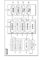
- FIG. 2 is a block diagram showing a hardware configuration of a touch panel type information terminal device according to an embodiment of the present invention.
- FIG. 3 is a block diagram showing a software configuration of a touch panel type information terminal device according to an embodiment of the present invention.
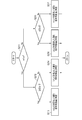
- FIG. 4 is a flowchart showing an example of a processing procedure and processing contents executed by the software of the touch panel type information terminal device shown in FIG.
- FIG. 5 is a flowchart showing an example of a processing procedure and processing contents of the operation target surface determination processing among the processes shown in FIG.
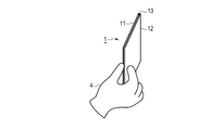
- FIG. 6 is a diagram showing a first example of a knob operation on the touch panel.
- FIG. 1 is a schematic configuration diagram of a touch panel type information terminal device according to an embodiment of the present invention.
- FIG. 2 is a block diagram showing a hardware configuration of a touch panel type information terminal device according to an embodiment of the present invention.
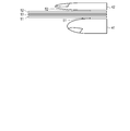
- FIG. 7 is a side view showing an example of a finger contact state with the touch panel when the knob operation shown in FIG. 6 is performed.
- FIG. 8 is a diagram showing a second example of a knob operation on the touch panel.
- FIG. 9 is a side view showing an example of a finger contact state with the touch panel when the knob operation shown in FIG. 8 is performed.
- FIG. 10 is a plan view showing an example of an operation position when a knob operation is performed on the touch panel from the upper side thereof.
- FIG. 11 is a plan view showing an example of an operation position when a knob operation is performed on the touch panel from the lower side thereof.
- FIG. 12 is a plan view showing an example of an operation position when a knob operation is performed on the touch panel from the left side side thereof.
- FIG. 13 is a plan view showing an example of an operation position when a knob operation is performed on the touch panel from the right side thereof.
- FIG. 14 is a diagram for explaining an example of a process of determining the operation target surface of
- FIG. 1 is a schematic configuration diagram of a touch panel type information terminal device according to an embodiment of the present invention.
- the touch panel type information terminal device according to the present embodiment includes a touch panel type user interface unit 1 and a terminal device main body 2.
- the user interface unit 1 arranges the first input device 11 on the first surface of the sheet-shaped display device 13, and also arranges the first input device 11 on the second surface of the display device 13 on the back side of the first surface.
- the input device 12 of 2 is arranged, and these display devices 13, the first and second input devices 11 and 12 are connected to the terminal device main body 2 via the signal line 3. That is, the user interface unit 1 has a structure in which the display device 13 is sandwiched between the first and second input devices 11 and 12.
- the display device 13 is composed of, for example, a device using a liquid crystal or an organic EL, and displays display data output from the terminal device main body 2.
- a display device using a transparent material may be used as the display device 13.
- Augmented Reality (AR) display can be performed, and the user can pass through the display device 13 and superimpose the information on the real space such as the surrounding scenery on the digital information related thereto. Can be confirmed.
- AR Augmented Reality
- the first and second input devices 11 and 12 are both transparent sheet-shaped devices, and when the surface is touch-operated, the touch position is detected by, for example, a capacitance method, and the detection signal is detected by a terminal. Input to the device body 2.
- the input devices 11 and 12 are hereinafter also referred to as touch panels. Further, as the touch operation detection method, it is also possible to adopt other methods such as a pressure detection method in addition to the capacitance method.
- FIG. 2 is a block diagram showing the hardware configuration of the terminal device main body 2 together with the user interface unit 1.
- the terminal device main body 2 includes a hardware processor (hereinafter also referred to as a CPU) 21 such as a Central Processing Unit (CPU), and the memory 22, the wireless interface unit 23, and the user interface unit 1 are bused to the CPU 21. It is connected via 24. It is also possible to connect other devices such as a camera, a microphone, and a speaker to the CPU 21.
- a hardware processor hereinafter also referred to as a CPU
- CPU Central Processing Unit
- the memory 22 uses a non-volatile memory such as Solid State Drive (SSD) that can be written and read at any time as a storage medium, and has a program storage area and a data storage area.
- SSD Solid State Drive
- a middleware program that functions as an Operation System (OS) and various application programs are stored in the program storage area.
- OS Operation System
- data storage area various data acquired and generated in the process of the terminal device main body 2 executing various processes according to the present invention are stored.
- ROM ReadOnlyMemory
- RAM RandomAccessMemory
- the wireless interface unit 23 uses, for example, a mobile phone network, a wireless Local Area Network (LAN), or a short-range wireless data communication network (for example, Bluetooth (registered trademark)) to communicate with a terminal or a website. Wireless communication with.
- a mobile phone network for example, a wireless Local Area Network (LAN), or a short-range wireless data communication network (for example, Bluetooth (registered trademark)) to communicate with a terminal or a website.
- LAN Local Area Network
- Bluetooth registered trademark
- FIG. 3 is a block diagram showing the software configuration of the terminal device main body 2 in association with the hardware configuration shown in FIG.
- the data storage area of the memory 22 is provided with a coordinate storage unit 221, a determination information storage unit 222, a display data storage unit 223, and a recognition data storage unit 224 as storage units necessary for carrying out the present embodiment. Has been done.
- the display data storage unit 223 stores the display data being displayed on the display device 13.
- the display data includes, for example, a plurality of software buttons (for example, icons) that are candidates for selection of processing.
- the CPU 21 includes an operation coordinate detection unit 211, an input device determination unit 212, an operation target surface determination unit 213, a referent recognition unit 214, and a processing execution unit 215 as processing units necessary for implementing the present embodiment. And have. All of these processing units 211 to 215 are realized by causing the CPU 21 to execute a program stored in the program storage area in the memory 22.
- the operation coordinate detection unit 211 is the first and second input devices 11 and 12 when a touch operation is performed on one or both of the first and second input devices 11 and 12 of the user interface unit 1.
- the detection signal indicating the touch position is captured from.
- the touch position coordinates are detected based on the captured detection signal, and the position coordinate data is stored in the coordinate storage unit 221 in the memory 22.
- the input device determination unit 212 takes in the detection signal from the operation coordinate detection unit 211, and based on this detection signal, has the touch operation been performed on only one of the first and second input devices 11 and 12. , Or both are determined at the same time. Then, a process of storing the information representing the determination result in the determination information storage unit 222 in the memory 22 is performed.
- the information representing the determination result for example, the identification information of the input device in which the touch operation is detected is used.
- the operation of touching both the first and second input devices 11 and 12 at the same time is, for example, an operation of pinching or pinching the user interface unit 1 between the thumb and other fingers. Also called “operation" (Pinch Control).
- the operation target surface determination unit 213 determines that the pinching operation has been performed by the input device determination unit 212
- the operation target surface determination unit 213 reads the position coordinates of the touch operation for each of the input devices 11 and 12 at this time from the coordinate storage unit 221. , Performs a process of determining the input device that is the operation target surface based on these position coordinates.
- the determination of the input device that is the operation target surface is performed, for example, by determining the input device on the side touch-operated by the thumb.
- the instruction target recognition unit 214 has the position coordinates of the touch operation stored in the coordinate storage unit 221 and the coordinates representing the display areas of the plurality of software buttons included in the display data stored in the display data storage unit 223. Based on this, it recognizes which software button the above touch operation indicates. Then, a process of storing the recognition data of the referent in the recognition data storage unit 224 is performed.
- the processing execution unit 215 includes the recognition data of the instruction target stored in the recognition data storage unit 224, the determination information of the touch-operated input device stored in the determination information storage unit 222, and the operation target surface. Based on the identification information of the input device determined to be the operation target surface by the determination unit 213, the corresponding application program is read from the program storage area in the memory 22 and executed by the CPU.
- FIG. 4 is a flowchart showing the entire processing procedure and processing content.
- the display data is not limited to software buttons (icons), and link destination information such as URLs may be displayed, and the number of icons and the like displayed at the same time is not limited to one.
- the CPU 21 refers to the first and second input devices (touch panels) 11 and 12 in step S10 under the control of the operation coordinate detection unit 211.
- the touch operation is monitored. In this state, it is assumed that the user touches the touch panels 11 and 12 with a fingertip, for example.
- the CPU 21 detects the touch operation in step S10, under the control of the operation coordinate detection unit 211, the CPU 21 is based on the detection signals output from the first and second input devices 11 and 12, respectively, in steps S11 and S12. Detect touch position coordinates. Then, the detected touch position coordinates are stored in the coordinate storage unit 221. By this process, the touch position coordinates of any one or both of the input devices 11 and 12 touch-operated by the user can be obtained.
- the CPU 21 first determines in step S13 whether or not the first input device 11 is the only input device for which the position coordinates of the touch operation have been obtained. As a result of this determination, if only the first input device 11 is used, the CPU 21 displays the touch position coordinates detected in the first input device 11 in step S14 under the control of the referent recognition unit 214. It is determined whether or not it is within the detection area corresponding to the software button (icon) A displayed on 13. Then, if the touch position coordinates are within the detection area corresponding to the software button (icon) A, the CPU 21 performs the touch-operated first input device 11 in step S15 under the control of the processing execution unit 215. The application A1 corresponding and associated with the software button (icon) A is selected and executed as one of the first processes.
- the CPU 21 If the touch position coordinates are not within the detection area corresponding to the software button (icon) A, the CPU 21 returns to the standby state of the touch operation in step S10.
- step S16 it is determined in step S16 whether or not the input device for which the position coordinates of the touch operation are obtained is the second input device 12.
- the CPU 21 displays the touch position coordinates detected in the second input device 12 on the display device 13 in step S17 under the control of the referent recognition unit 214. It is determined whether or not it is within the detection area corresponding to the displayed software button (icon) A. Then, if the touch position coordinates are within the detection area corresponding to the software button (icon) A, the CPU 21 sends the second input device 12 to the touch-operated second input device 12 in step S18 under the control of the processing execution unit 215.
- the application A2 corresponding and associated with the software button (icon) A is selected and executed as one of the first processes.
- the CPU 21 If the touch position coordinates are not within the detection area corresponding to the software button (icon) A, the CPU 21 returns to the standby state of the touch operation in step S10.
- FIG. 6 is a diagram showing an example of "Pinch operation".
- the user interface unit 1 is touched with the thumb 41 of the hand 4 and other fingers (for example, the index finger or the middle finger) 42 so as to grip the unit 1 from the vertical direction in a state where the user interface unit 1 is substantially horizontal. ..
- a difference occurs between the contact position 51 of the thumb 41 and the contact position 52 of the other fingers 42 with respect to the first and second input devices 11 and 12, as shown in FIG. 7, for example.
- the contact position 51 of the thumb 41 is closer to the end side of the user interface unit 1 than the contact position 52 of the other fingers 42.
- FIG. 8 is a diagram showing another example of "pinch operation".
- the user interface unit 1 is touched with the thumb 41 of the hand 4 and other fingers (for example, the index finger or the middle finger) 42 so as to grip the unit 1 from the left and right in a state where the user interface unit 1 is substantially vertical.
- other fingers for example, the index finger or the middle finger
- a difference occurs between the contact position 51 of the thumb 41 and the contact position 52 of the other fingers 42 with respect to the first and second input devices 11 and 12, as shown in FIG. 9, for example.
- the contact position 51 of the thumb 41 is closer to the end side of the user interface unit 1 than the contact position 52 of the other fingers 42.
- the CPU 21 subsequently controls the operation target surface determination unit 213, and in step S21, the operation target surface is first. And which side of the second input devices 11 and 12 is determined.
- FIG. 5 is a flowchart showing the determination processing procedure and the processing content.
- 10 to 13 show the operation directions of the four kinds of assumed “pinch operations”, and
- FIG. 14 shows an enlarged view of the operations shown in FIG.
- a thumb 41 and another finger 42 pinch from the upper end side of the touch panel (FIG. 10), and a thumb from the lower end side of the touch panel.
- Fig. 11 When pinching with 41 and other fingers 42 (Fig. 11), when pinching with thumb 41 and other fingers 42 from the left end side of the touch panel (Fig. 12), and when pinching with the thumb 41 and other fingers from the right end side of the touch panel.
- a case of pinching with a finger 42 (FIG. 13) can be considered.
- the touch position coordinates P1 and P2 by the thumb 41 and the other fingers 42 are set to (x1, y1) and (x2, y2), respectively.
- the CPU 21 Under the control of the operation target surface determination unit 213, the CPU 21 first takes a step S211 between the touch position coordinates P1 (x1, y1) of the thumb 41 and the touch position coordinates P2 (x2, y2) of the other finger 42. The difference (xa, ya) is calculated, and it is determined whether or not xa ⁇ ya. By this determination, it is possible to identify whether the "pinch operation" is performed from the upper and lower end sides of the touch panel or from the left and right end sides.
- step S211 If it is determined in step S211 that xa ⁇ ya, that is, it is determined that the "pinch operation" is performed from the upper end side or the lower end side of the touch panel as shown in FIGS. 10 and 11.
- the CPU 21 determines in step S212 whether or not
- the input device in which the position coordinates P1 (x1, y1) are detected in step S214 is recognized as the operation target surface.
- the result of the above determination is
- step S211 determines whether or not
- the CPU 21 determines in step S215 whether or not
- the input device in which the position coordinates P1 (x1, y1) are detected in step S217 is recognized as the operation target surface.
- the input device in which the position coordinates P2 (x2, y2) are detected in step S216 is recognized as the operation target surface.
- the input device whose position coordinates of the touch operation with respect to the first and second input devices 11 and 12 are close to the ends of the input devices 11 and 12 is the operation target surface, that is, the touch. It is determined that the input device is the target for inputting instructions by operation.
- the CPU 21 When the determination process of the operation target surface is completed, the CPU 21 subsequently inputs in step S22 the instruction target surface (operation surface by the thumb) by the "pinch operation" based on the determination result of the operation target surface. It is determined whether it is the device 11 or the second input device 12. As a result of this determination, when the referent surface (operation surface by the thumb) is the first input device 11, the CPU 21 executes the process by the application A12 in step S24 under the control of the process execution unit 215.
- step S22 when the referent surface (operation surface by the thumb) is the second input device 12, the CPU 21 performs the processing by the application A21 in step S23 under the control of the processing execution unit 215. Execute.
- the touch operation on the first and second input devices 11 and 12 is performed on only one of the first and second input devices 11, or simultaneously on both. It is determined whether it has been damaged (whether the "pinch operation" has been performed). Then, based on the determination result, different processes are executed depending on whether the touch operation is performed only on the first input device 11 or only on the second input device 12. There is.
- the first and second input devices 11 and 12 are arranged on both the front and back surfaces of the display device 13, and a touch operation is performed on only one of these input devices 11 and 12.
- So-called "pinch operation” that touches both at the same time is judged, and a plurality of different processes are selected and executed according to the combination of the judgment result and the software button (icon) specified by the touch operation. Therefore, it is possible to selectively specify various types of processing without increasing the size of the input devices 11 and 12 and without reducing the display size of software buttons (icons) and the like. Become.
- the "pinch operation" is performed with the thumb and other fingers such as the index finger and middle finger longer than that, and the icon instruction is often performed with the thumb. Therefore, in one embodiment, when a "pinch operation" is performed, a finger on each of the input devices 11 and 12 indicates whether the input device to be input of the operation instruction is the first input device or the second input device. Judgment is made based on the difference in the position coordinates of the touch operation of. Therefore, it is possible to accurately determine the input device to which the operation instruction is input when the "pinch operation" is performed.
- the contact area between the thumb 41 and the other fingers 42 with respect to the first and second input devices 11 and 12 is generally, for example, FIG. As illustrated in FIG. 9, the other fingers 42 are larger than the thumb 41. Therefore, the CPU 21 determines the difference in the contact area of the finger with respect to each of the input devices 11 and 12 based on the detection signals output from the first and second input devices 11 and 12, and uses the determination result as the determination result. Based on which side of the first and second input devices 11 and 12 is touch-operated by the thumb 41, that is, which of the first and second input devices 11 and 12 is input as an operation instruction. It may be determined whether or not it is the target. Further, not only the difference in the contact area but also the difference in the contact shape is determined, and based on the determination result, it is determined which of the first and second input devices 11 and 12 is the input target of the operation instruction. You may try to do it.
- the structure of the user interface unit 1, the materials of the display devices 13 and the input devices 11 and 12, and the procedure and processing contents of the information input processing in the terminal device main body are also variously modified without departing from the gist of the present invention. It is feasible.
- the present invention is not limited to the above embodiment, and can be variously modified at the implementation stage without departing from the gist thereof.
- each embodiment may be carried out in combination as appropriate as possible, in which case the combined effect can be obtained.
- the above-described embodiment includes inventions at various stages, and various inventions can be extracted by an appropriate combination in a plurality of disclosed constituent requirements.
Landscapes
- Engineering & Computer Science (AREA)
- General Engineering & Computer Science (AREA)
- Theoretical Computer Science (AREA)
- Human Computer Interaction (AREA)
- Physics & Mathematics (AREA)
- General Physics & Mathematics (AREA)
- User Interface Of Digital Computer (AREA)
- Position Input By Displaying (AREA)
Abstract
表示デバイスの両面に第1および第2の入力デバイスを配置したユーザインタフェースユニットを備え、端末装置本体のハードウェアプロセッサにより、第1および第2の入力デバイスから出力される各検出信号に基づいて、タッチ操作が第1および第2の入力デバイスの一方のみに行われたか又は両方に対し同時に行われたかを判定し、その判定結果に応じて第1の処理と第2の処理を選択的に実行する。
Description
この発明の一態様は、タッチパネル型入力インタフェースを備えたタッチパネル型情報端末装置と、この装置により実行される情報入力処理方法に関する。
スマートフォンやタブレット型端末等のように表示画面上に入力シートを配置したタッチパネルを有する情報端末装置が普及している。この種の装置では、表示画面を指で直接タッチすることにより操作対象を指定することができるため、直感的な操作が可能である。さらに、マウスやタッチパッド等の外付けの入力デバイスが不要であることから、可搬性に優れた機器形状を実現できるという利点がある。
例えば、特許文献1には、表示画面上にソフトウェアボタン(アイコン)やUniform Resource Locator(URL)等のリンク先情報を表示し、その表示領域に対応する入力シート上の入力領域が指先等でタップされたとき、タップされた位置座標をもとに上記ソフトウェアボタンやリンク先情報を認識して所定の処理を実行する装置が記載されている。
ところが、従来のタッチパネル型情報端末装置は、表示画面の一方の面に入力シートを配置した構造であるため、タッチ操作による入力領域が上記単一の入力シート上のみとなり、一度に表示可能なソフトウェアボタン(アイコン)の数が限られる。通常、1個のアイコンには1種類の処理が割り当てられるため、指定可能な処理の種類も上記入力領域のサイズにより制限される。上記入力領域を増やすには端末装置のサイズを大型化するか、或いはアイコンのサイズを小さくする必要があり、このようにすると端末装置の大型化又は操作性の低下を招く。
この発明は上記事情に着目してなされたもので、その一側面では、端末装置のサイズの大型化や操作性の低下を生じることなく多数の処理を指定できるようにする技術を提供しようとするものである。
この発明に係る第1の態様は、第1の面および当該第1の面の背面側となる第2の面を有する表示デバイスと、前記表示デバイスの第1の面に配置されタッチ操作に応じてそのタッチ位置に対応する検出信号を出力する第1の入力デバイスと、前記表示デバイスの第2の面に配置されタッチ操作に応じてそのタッチ位置に対応する検出信号を出力する第2の入力デバイスと、前記表示デバイス、前記第1および第2の入力デバイスに接続される端末装置本体とを具備する。このうち端末装置本体は、ハードウェアプロセッサと当該ハードウェアプロセッサが実行するプログラムを少なくとも記憶したメモリとを備える。前記ハードウェアプロセッサは、前記第1および第2の入力デバイスから出力される各検出信号に基づいて、前記タッチ操作が前記第1および第2の入力デバイスの一方のみに行われたか又は両方に対し同時に行われたかを判定し、前記タッチ操作が前記第1および第2の入力デバイスの一方のみに行われたと判定された場合に、当該タッチ操作が行われた入力デバイスから出力された前記検出信号に基づいて第1の処理を実行し、前記タッチ操作が前記第1および第2の入力デバイスの両方に対し同時に行われたと判定された場合に、当該第1または第2の入力デバイスから出力された前記検出信号に基づいて第2の処理を実行するように構成される。
この発明に係る第1の態様によれば、その一側面において、端末装置のサイズの大型化や操作性の低下を生じることなく多数の処理を指定できるようにした技術を提供することができる。
以下、図面を参照してこの発明に係わる実施形態を説明する。
[一実施形態]
(構成)
図1は、この発明の一実施形態に係るタッチパネル型情報端末装置の概略構成図である。本実施形態に係るタッチパネル型情報端末装置は、タッチパネル型のユーザインタフェースユニット1と、端末装置本体2とを備える。
[一実施形態]
(構成)
図1は、この発明の一実施形態に係るタッチパネル型情報端末装置の概略構成図である。本実施形態に係るタッチパネル型情報端末装置は、タッチパネル型のユーザインタフェースユニット1と、端末装置本体2とを備える。
(1)ユーザインタフェースユニット1
ユーザインタフェースユニット1は、シート状をなす表示デバイス13の第1の面に第1の入力デバイス11を配置すると共に、表示デバイス13の上記第1の面の背面側となる第2の面に第2の入力デバイス12を配置し、これらの表示デバイス13、第1および第2の入力デバイス11,12を、信号線3を介して上記端末装置本体2に接続したものとなっている。すなわち、ユーザインタフェースユニット1は、表示デバイス13を第1および第2の入力デバイス11,12によりサンドイッチした構造をなす。
ユーザインタフェースユニット1は、シート状をなす表示デバイス13の第1の面に第1の入力デバイス11を配置すると共に、表示デバイス13の上記第1の面の背面側となる第2の面に第2の入力デバイス12を配置し、これらの表示デバイス13、第1および第2の入力デバイス11,12を、信号線3を介して上記端末装置本体2に接続したものとなっている。すなわち、ユーザインタフェースユニット1は、表示デバイス13を第1および第2の入力デバイス11,12によりサンドイッチした構造をなす。
表示デバイス13は、例えば液晶又は有機ELを用いたデバイスからなり、端末装置本体2から出力される表示データを表示する。なお、表示デバイス13としては、透明材料を使用したディスプレイデバイスを使用してもよい。この種の表示デバイスを使用すると、例えばAugmented Reality(AR)表示を行うことが可能となり、ユーザは表示デバイス13を透過して周辺の景色等の現実空間の情報に重ねてそれに関連するディジタル情報等を確認することが可能となる。
第1および第2の入力デバイス11,12は、何れも透明なシート状のデバイスからなり、表面をタッチ操作された場合にそのタッチ位置を例えば静電容量方式により検出してその検出信号を端末装置本体2に入力する。なお、各入力デバイス11,12を以後タッチパネルとも云う。また、タッチ操作の検出方式としては、静電容量方式以外に圧力検出方式等のその他方式を採用することも可能である。
(2)端末装置本体2
図2は、端末装置本体2のハードウェア構成を上記ユーザインタフェースユニット1と共に示したブロック図である。
端末装置本体2は、Central Processing Unit(CPU)等のハードウェアプロセッサ(以後CPUとも云う)21を備え、このCPU21に対し、メモリ22と、無線インタフェースユニット23と、上記ユーザインタフェースユニット1を、バス24を介して接続したものとなっている。なお、上記CPU21には、カメラやマイクロフォン、スピーカ等の他のデバイスを接続することも可能である。
図2は、端末装置本体2のハードウェア構成を上記ユーザインタフェースユニット1と共に示したブロック図である。
端末装置本体2は、Central Processing Unit(CPU)等のハードウェアプロセッサ(以後CPUとも云う)21を備え、このCPU21に対し、メモリ22と、無線インタフェースユニット23と、上記ユーザインタフェースユニット1を、バス24を介して接続したものとなっている。なお、上記CPU21には、カメラやマイクロフォン、スピーカ等の他のデバイスを接続することも可能である。
メモリ22は、記憶媒体として例えばSolid State Drive(SSD)等の随時書込みおよび読出しが可能な不揮発性メモリを用いたもので、プログラム記憶領域とデータ記憶領域とを有する。プログラム記憶領域には、Operation System(OS)として機能するミドルウェアプログラムと、種々アプリケーション・プログラムが格納される。データ記憶領域には、端末装置本体2がこの発明に係る各種処理を実行する過程で取得および生成される各種データが保存される。なお、記憶媒体としては、他にRead Only Memory(ROM)やRandom Access Memory(RAM)を備えるようにしてもよい。
無線インタフェースユニット23は、CPU21の制御の下、例えば携帯電話網や無線Local Area Network(LAN)、近距離無線データ通信網(例えばBluetooth(登録商標))を使用して、通信相手端末またはWebサイトとの間で無線通信を行う。
図3は、端末装置本体2のソフトウェア構成を、図2に示したハードウェア構成と関連付けて示したブロック図である。
メモリ22のデータ記憶領域には、本実施形態を実施するために必要な記憶部として、座標記憶部221と、判定情報記憶部222と、表示データ記憶部223と、認識データ記憶部224が設けられている。このうち表示データ記憶部223には、表示デバイス13に表示中の表示データが保存される。表示データには、例えば処理の選択候補となる複数のソフトウェアボタン(例えばアイコン)が含まれる。
メモリ22のデータ記憶領域には、本実施形態を実施するために必要な記憶部として、座標記憶部221と、判定情報記憶部222と、表示データ記憶部223と、認識データ記憶部224が設けられている。このうち表示データ記憶部223には、表示デバイス13に表示中の表示データが保存される。表示データには、例えば処理の選択候補となる複数のソフトウェアボタン(例えばアイコン)が含まれる。
CPU21は、本実施形態を実施するために必要な処理部として、操作座標検出部211と、入力デバイス判定部212と、操作対象面判定部213と、指示対象認識部214と、処理実行部215とを有している。これらの処理部211~215はいずれも上記メモリ22内のプログラム記憶領域に格納されたプログラムをCPU21に実行させることにより実現される。
操作座標検出部211は、上記ユーザインタフェースユニット1の第1および第2の入力デバイス11、12の一方または両方に対しタッチ操作が行われた場合に、第1および第2の入力デバイス11,12からタッチ位置を表す検出信号を取り込む。そして、取り込んだ検出信号をもとにタッチ位置座標を検出し、その位置座標データをメモリ22内の座標記憶部221に保存させる処理を行う。
入力デバイス判定部212は、上記操作座標検出部211から上記検出信号を取り込み、この検出信号に基づいて、上記タッチ操作が上記第1および第2の入力デバイス11,12の一方のみに行われたか、或いは両方に対し同時に行われたかを判定する。そして、その判定結果を表す情報をメモリ22内の判定情報記憶部222に保存させる処理を行う。判定結果を表す情報としては、例えばタッチ操作が検出された入力デバイスの識別情報が用いられる。
なお、第1および第2の入力デバイス11,12の両方に対し同時にタッチする操作は、例えば親指とその他の指とでユーザインタフェースユニット1を挟む或いはつまむような操作となることから、以後「つまむ操作」(Pinch Control)とも呼称する。
操作対象面判定部213は、上記入力デバイス判定部212によりつまむ操作が行われたと判定された場合に、このときの各入力デバイス11,12に対するタッチ操作の位置座標を上記座標記憶部221から読み込み、これらの位置座標をもとに操作対象面となった入力デバイスを判定する処理を行う。操作対象面となった入力デバイスの判定は、例えば親指でタッチ操作された側の入力デバイスを判定することで行われる。
指示対象認識部214は、上記座標記憶部221に保存されているタッチ操作の位置座標と、表示データ記憶部223に記憶された表示データに含まれる複数のソフトウェアボタンの表示領域を表す座標とをもとに、上記タッチ操作が何れのソフトウェアボタンを指示したものかを認識する。そして、この指示対象の認識データを認識データ記憶部224に保存させる処理を行う。
処理実行部215は、上記認識データ記憶部224に保存されている指示対象の認識データと、上記判定情報記憶部222に保存されているタッチ操作された入力デバイスの判定情報と、上記操作対象面判定部213により操作対象面と判定された入力デバイスの識別情報とに基づいて、対応するアプリケーション・プログラムをメモリ22内のプログラム記憶領域から読み出し、CPUに実行させる。
(動作)
次に、以上のように構成されたタッチパネル型情報端末装置による情報入力処理動作について説明する。図4はその全体の処理手順と処理内容を示すフローチャートである。
次に、以上のように構成されたタッチパネル型情報端末装置による情報入力処理動作について説明する。図4はその全体の処理手順と処理内容を示すフローチャートである。
表示デバイス13には、例えば処理候補となるアプリケーションに対応付けられたソフトウェアボタン(アイコン)Aが表示されているものとする。なお、表示データとしては、ソフトウェアボタン(アイコン)に限らずURL等のリンク先情報が表示されるようにしてもよいし、同時に表示されるアイコン等の数も1個に限らない。
(1)第1の入力デバイス11のみへのタッチ操作が行われた場合
CPU21は、操作座標検出部211の制御の下、ステップS10により第1および第2の入力デバイス(タッチパネル)11,12に対するタッチ操作を監視している。この状態で、ユーザが例えばタッチパネル11,12に対し指先でタッチ操作をしたとする。
CPU21は、操作座標検出部211の制御の下、ステップS10により第1および第2の入力デバイス(タッチパネル)11,12に対するタッチ操作を監視している。この状態で、ユーザが例えばタッチパネル11,12に対し指先でタッチ操作をしたとする。
CPU21は、上記タッチ操作をステップS10で検出すると、操作座標検出部211の制御の下、ステップS11,S12においてそれぞれ第1および第2の入力デバイス11,12から出力される検出信号をもとにタッチ位置座標を検出する。そして、この検出されたタッチ位置座標を座標記憶部221に保存させる。この処理により、ユーザがタッチ操作した入力デバイス11,12のいずれか一方、或いは両方のタッチ位置座標が得られる。
CPU21は、次に入力デバイス判定部212の制御の下、先ずステップS13により、タッチ操作の位置座標が得られた入力デバイスは第1の入力デバイス11のみであるか否かを判定する。この判定の結果、第1の入力デバイス11のみであれば、CPU21は指示対象認識部214の制御の下、ステップS14により、上記第1の入力デバイス11において検出されたタッチ位置座標が、表示デバイス13に表示中のソフトウェアボタン(アイコン)Aに対応する検出領域内であるか否かを判定する。そして、上記タッチ位置座標がソフトウェアボタン(アイコン)Aに対応する検出領域内であれば、CPU21は処理実行部215の制御の下、ステップS15において、上記タッチ操作された第1の入力デバイス11に対応し、かつ上記ソフトウェアボタン(アイコン)Aに対応付けられたアプリケーションA1を、第1の処理の一つとして選択し実行する。
なお、タッチ位置座標がソフトウェアボタン(アイコン)Aに対応する検出領域内でなければ、CPU21はステップS10によるタッチ操作の待受状態に戻る。
(2)第2の入力デバイス12のみへのタッチ操作が行われた場合
CPU21は、上記ステップS13において、タッチ操作の位置座標が得られた入力デバイスが第1の入力デバイス11でなかったとすると、入力デバイス判定部212の制御の下、タッチ操作の位置座標が得られた入力デバイスが第2の入力デバイス12であるか否かをステップS16により判定する。
CPU21は、上記ステップS13において、タッチ操作の位置座標が得られた入力デバイスが第1の入力デバイス11でなかったとすると、入力デバイス判定部212の制御の下、タッチ操作の位置座標が得られた入力デバイスが第2の入力デバイス12であるか否かをステップS16により判定する。
この判定の結果、第2の入力デバイス12であれば、CPU21は指示対象認識部214の制御の下、ステップS17により、上記第2の入力デバイス12において検出されたタッチ位置座標が表示デバイス13に表示中のソフトウェアボタン(アイコン)Aに対応する検出領域内であるか否かを判定する。そして、上記タッチ位置座標がソフトウェアボタン(アイコン)Aに対応する検出領域内であれば、CPU21は処理実行部215の制御の下、ステップS18において、上記タッチ操作された第2の入力デバイス12に対応し、かつ上記ソフトウェアボタン(アイコン)Aに対応付けられたアプリケーションA2を、第1の処理の一つとして選択し実行する。
なお、タッチ位置座標がソフトウェアボタン(アイコン)Aに対応する検出領域内でなければ、CPU21はステップS10によるタッチ操作の待受状態に戻る。
すなわち、本実施形態では、同一のソフトウェアボタン(アイコン)Aがタッチ操作された場合でも、タッチ操作された入力デバイスが第1の入力デバイス11であるか第2の入力デバイス12であるかによって異なるアプリケーションA1,A2が選択され、実行される。
(3)第1および第2の入力デバイス11,12に対する「つまむ操作」が行われた場合
図6は「つまむ操作」の一例を示す図である。この操作形態は、ユーザインタフェースユニット1をほぼ水平にした状態で、手4の親指41とその他の指(例えば人差し指又は中指)42とでユニット1を上下方向から把持するようにタッチするものである。この場合、通常では、第1および第2の入力デバイス11,12に対する親指41の接触位置51と他の指42の接触位置52との間には、例えば図7に示すように差が発生し、親指41の接触位置51の方が他の指42の接触位置52よりユーザインタフェースユニット1の端部側に近い位置となる。
図6は「つまむ操作」の一例を示す図である。この操作形態は、ユーザインタフェースユニット1をほぼ水平にした状態で、手4の親指41とその他の指(例えば人差し指又は中指)42とでユニット1を上下方向から把持するようにタッチするものである。この場合、通常では、第1および第2の入力デバイス11,12に対する親指41の接触位置51と他の指42の接触位置52との間には、例えば図7に示すように差が発生し、親指41の接触位置51の方が他の指42の接触位置52よりユーザインタフェースユニット1の端部側に近い位置となる。
図8は「つまむ操作」の他の例を示す図である。この操作形態は、ユーザインタフェースユニット1をほぼ垂直にした状態で、手4の親指41とその他の指(例えば人差し指又は中指)42とでユニット1を左右から把持するようにタッチするものである。この場合も、通常では、第1および第2の入力デバイス11,12に対する親指41の接触位置51と他の指42の接触位置52との間には、例えば図9に示すように差が発生し、親指41の接触位置51の方が他の指42の接触位置52よりユーザインタフェースユニット1の端部側に近い位置となる。
CPU21は、入力デバイス判定部212の制御の下、ステップS19において、タッチ操作の位置座標が得られた入力デバイスが第1および第2の入力デバイス11,12の両方であるか否かを判定する。この判定の結果、タッチ操作が第1および第2の入力デバイス11,12の両方にほぼ同時に行われたと判定すると、つまり「つまみ操作」が行われたと判定すると、CPU21は指示対象認識部214の制御の下、ステップS20において、上記第1および第2の入力デバイス11,12においてそれぞれ検出されたタッチ位置座標が表示デバイス13に表示中のソフトウェアボタン(アイコン)Aに対応する検出領域内であるか否かを判定する。
上記判定の結果、タッチ位置座標がソフトウェアボタン(アイコン)Aに対応する検出領域内であれば、CPU21は続いて操作対象面判定部213の制御の下、ステップS21において、操作対象面が第1および第2の入力デバイス11,12の何れの側であるかを判定する。
ここで、スマートフォン等のタッチパネル型端末をタッチ操作する場合、ユーザは一般に親指でタッチ操作する場合が多い。そこで、「つまむ操作」が行われた場合にも、親指により操作された面が指示操作が行われた操作対象面であると認識する。
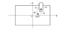
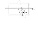
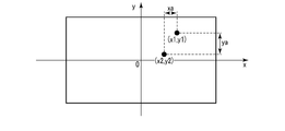
以下、操作対象面判定処理の一例を詳しく説明する。図5はその判定処理手順と処理内容を示すフローチャートである。図10~図13は想定される4種類の「つまむ操作」の操作方向を示し、また図14はそのうちの図10に示した操作を拡大して示したものである。
図10~図13に示すように、ユーザが「つまむ操作」を行う場合、タッチパネルの上端辺側から親指41と他の指42とでつまむ場合(図10)と、タッチパネルの下端辺側から親指41と他の指42とでつまむ場合(図11)と、タッチパネルの左端辺側から親指41と他の指42とでつまむ場合(図12)と、タッチパネルの右端辺側から親指41と他の指42とでつまむ場合(図13)が考えられる。なお、親指41および他の指42によるタッチ位置座標P1,P2をそれぞれ(x1,y1),(x2,y2)とする。
CPU21は、操作対象面判定部213の制御の下、先ずステップS211において、親指41のタッチ位置座標P1(x1,y1)と、他の指42のタッチ位置座標P2(x2,y2)との間の差(xa,ya)を算出し、xa<yaであるか否かを判定する。この判定により、「つまむ操作」がタッチパネルの上下端辺側から行われたものか、左右端辺側から行われたものかを識別できる。
上記ステップS211によりxa<yaと判定されると、つまり「つまむ操作」が図10および図11に示したようにタッチパネルの上端辺側又は下端辺側から行われたと判定される。この場合CPU21は、ステップS212により|y2|>|y1|であるか否かを判定する。この判定の結果、|y2|<|y1|であれば、ステップS214により、位置座標P1(x1,y1)が検出された入力デバイスを操作対象面と認識する。これに対し、上記判定の結果|y2|>|y1|であれば、ステップS213により、位置座標P2(x2,y2)が検出された入力デバイスを操作対象面と認識する。
一方、上記ステップS211によりxa>yaと判定されると、つまり「つまむ操作」が図12および図13に示したようにタッチパネルの左端辺側又は右端辺側から行われたと判定される。この場合CPU21は、ステップS215により|x2|>|x1|であるか否かを判定する。この判定の結果、|x2|<|x1|であれば、ステップS217により、位置座標P1(x1,y1)が検出された入力デバイスを操作対象面と認識する。これに対し、上記判定の結果|x2|>|x1|であれば、ステップS216により、位置座標P2(x2,y2)が検出された入力デバイスを操作対象面と認識する。
すなわち、上記操作対象面の判定処理では、第1および第2の入力デバイス11,12に対するタッチ操作の位置座標が入力デバイス11,12の端部に近い入力デバイスが、上記操作対象面、つまりタッチ操作による指示の入力対象となる入力デバイスと判定される。
上記操作対象面の判定処理が終了すると、CPU21は続いてステップS22において、上記操作対象面の判定結果に基づいて、「つまむ操作」による指示対象面(親指による操作面)が、第1の入力デバイス11であるか第2の入力デバイス12であるかを判定する。この判定の結果、指示対象面(親指による操作面)が第1の入力デバイス11の場合、CPU21は処理実行部215の制御の下、ステップS24によりアプリケーションA12による処理を実行する。
これに対し、上記ステップS22による判定の結果、指示対象面(親指による操作面)が第2の入力デバイス12の場合、CPU21は処理実行部215の制御の下、ステップS23によりアプリケーションA21による処理を実行する。
すなわち、「つまむ操作」が行われた場合にも、親指41により第1および第2の入力デバイス11,12のうち何れがタッチ操作されたかに応じて、異なるアプリケーションA12,A21が第2の処理として選択され、実行される。
(効果)
以上述べたように一実施形態では、第1および第2の入力デバイス11,12に対するタッチ操作が、第1および第2の入力デバイス11の何れか一方のみ行われたか、或いは両方に対し同時に行われたか(「つまむ操作」が行われたか)を判定している。そして、その判定結果に基づいて、タッチ操作が、第1の入力デバイス11のみに行われた場合と、第2の入力デバイス12のみに行われた場合とで、異なる処理を実行するようにしている。
以上述べたように一実施形態では、第1および第2の入力デバイス11,12に対するタッチ操作が、第1および第2の入力デバイス11の何れか一方のみ行われたか、或いは両方に対し同時に行われたか(「つまむ操作」が行われたか)を判定している。そして、その判定結果に基づいて、タッチ操作が、第1の入力デバイス11のみに行われた場合と、第2の入力デバイス12のみに行われた場合とで、異なる処理を実行するようにしている。
例えば、タッチ操作により同一のソフトウェアボタン(アイコン)が指示された場合でも、第1の入力デバイス11に対しタッチ操作された場合と、第2の入力デバイス12にタッチ操作された場合とで、異なるリンク先に対しアクセスする処理A1,A2を実行する場合が考えられる。
さらには、上記「つまむ操作」が行われた場合に、親指によりタッチ操作された面が第1の入力デバイス11側であるか、第2の入力デバイス12側で有るかを判定している。そして、その判定結果に応じて、親指によりタッチ操作された面が第1の入力デバイス11側の場合と、第2の入力デバイス12側の場合とで、異なる処理A12,A21を選択して実行するようにしている。例えば、処理A12,A21としては、それぞれ上記処理A1,A2によりダウンロードされ保存されているデータをメモリ22のデータ記憶領域から読み出して表示させる処理が考えられる。
また別の例として、カメラを起動するソフトウェアボタン(アイコン)が第1の入力デバイス11側からタッチ操作された場合には、静止画を撮像する処理を実行し、一方カメラを起動する上記ソフトウェアボタン(アイコン)が「つまむ操作」によりタッチ操作された場合には、動画を撮像する処理を実行することが考えられる。
以上のように一実施形態によれば、表示デバイス13の表裏両面に第1および第2の入力デバイス11,12を配置し、これらの入力デバイス11,12の何れか一方のみへのタッチ操作と、両方に対し同時にタッチするいわゆる「つまむ操作」とを判定し、その判定結果と、タッチ操作により指定されたソフトウェアボタン(アイコン)との組み合わせに応じて、異なる複数の処理を選択し実行するようにしたので、入力デバイス11,12のサイズのサイズを大型化することなく、またソフトウェアボタン(アイコン)等の表示サイズを縮小することなく、多種類の処理を選択的に指定することが可能となる。
この結果、例えば1個のアイコンに対し複数種類の処理を割り当て、第1および第2の入力デバイス11,12に対するタッチ操作の種類を変えることで、1個のアイコンを指定しているにもかかわらず、上記複数種類の処理を選択的に実行させることが可能となる。
すなわち、端末装置のサイズの大型化や操作性の低下を防止した上で、多種類の処理を選択的に指定し実行させることが可能となる。
また、一般に「つまむ操作」は親指とそれより長い人差し指や中指等のその他の指とで行われ、かつアイコンの指示は親指により行われることが多い。そこで一実施形態では、「つまむ操作」が行われた場合に、操作指示の入力対象となる入力デバイスが第1および第2の入力デバイスの何れであるかを、各入力デバイス11,12に対する指のタッチ操作の位置座標の差をもとに判定するようにしている。このため、「つまむ操作」が行われた場合の操作指示の入力対象となる入力デバイスを正確に判定することができる。
[他の実施形態]
(1)入力デバイス判定部212において、「つまむ操作」が行われたか否かを判定する際に、第1の入力デバイス11に対するタッチ操作の位置座標P1と、第2の入力デバイス12に対するタッチ操作の位置座標P2との間の差(xa,ya)を予め設定されているしきい値αと比較し、位置座標P1,P2間の差(xa,ya)がしきい値α以内の場合に「つまむ操作」と判定するようにしてもよい。
(1)入力デバイス判定部212において、「つまむ操作」が行われたか否かを判定する際に、第1の入力デバイス11に対するタッチ操作の位置座標P1と、第2の入力デバイス12に対するタッチ操作の位置座標P2との間の差(xa,ya)を予め設定されているしきい値αと比較し、位置座標P1,P2間の差(xa,ya)がしきい値α以内の場合に「つまむ操作」と判定するようにしてもよい。
このようにすると、例えば第1の入力デバイス11に対しタッチ操作した際に、誤って第2の入力デバイス12に他の手又は指が触れてしまった場合、このときの第1および第2の入力デバイス11,12に対するタッチ操作が「つまむ操作」として誤判定されないようにすることができる。
(2)親指41とその他の指42による「つまむ操作」が行われた場合、一般に第1および第2の入力デバイス11,12に対する親指41とその他の指42の接触面積は、例えば図7および図9に例示したように親指41よりその他の指42の方が大きくなる。そこで、CPU21により、第1および第2の入力デバイス11,12から出力される検出信号をもとに、これらの各入力デバイス11,12に対する指の接触面積の差異を判定し、その判定結果に基づいて親指41が第1および第2の入力デバイス11,12のうち何れの側をタッチ操作しているのか、つまり第1および第2の入力デバイス11,12のうちの何れを操作指示の入力対象としたかを判定するようにしてもよい。
また、接触面積の差異に限らず、接触形状の差異を判定し、その判定結果に基づいて第1および第2の入力デバイス11,12のうちの何れを操作指示の入力対象としたかを判定するようにしてもよい。
また、接触面積の差異に限らず、接触形状の差異を判定し、その判定結果に基づいて第1および第2の入力デバイス11,12のうちの何れを操作指示の入力対象としたかを判定するようにしてもよい。
その他、ユーザインタフェースユニット1の構造や表示デバイス13および各入力デバイス11,12の材質、端末装置本体における情報入力処理の手順と処理内容についても、この発明の要旨を逸脱しない範囲で種々変形して実施可能である。
すなわち、本発明は、上記実施形態に限定されるものではなく、実施段階ではその要旨を逸脱しない範囲で種々に変形することが可能である。また、各実施形態は可能な限り適宜組み合わせて実施してもよく、その場合組み合わせた効果が得られる。更に、上記実施形態には種々の段階の発明が含まれており、開示される複数の構成要件における適当な組み合わせにより種々の発明が抽出され得る。
1…ユーザインタフェースユニット
2…端末装置本体
3…信号線
11…第1の入力デバイス
12…第2の入力デバイス
13…表示デバイス
21…CPU
22…メモリ
23…無線インタフェースユニット
24…バス
41…親指
42…その他の指
211…操作座標検出部
212…入力デバイス判定部
213…操作対象面判定部
214…指示対象認識部
215…処理実行部
221…座標記憶部
222…判定情報記憶部
223…表示データ記憶部
224…認識データ記憶部
2…端末装置本体
3…信号線
11…第1の入力デバイス
12…第2の入力デバイス
13…表示デバイス
21…CPU
22…メモリ
23…無線インタフェースユニット
24…バス
41…親指
42…その他の指
211…操作座標検出部
212…入力デバイス判定部
213…操作対象面判定部
214…指示対象認識部
215…処理実行部
221…座標記憶部
222…判定情報記憶部
223…表示データ記憶部
224…認識データ記憶部
Claims (7)
- 第1の面および当該第1の面の背面側となる第2の面を有する表示デバイスと、
前記表示デバイスの前記第1の面に配置され、タッチ操作に応じてそのタッチ位置に対応する検出信号を出力する第1の入力デバイスと、
前記表示デバイスの前記第2の面に配置され、タッチ操作に応じてそのタッチ位置に対応する検出信号を出力する第2の入力デバイスと、
前記表示デバイス、前記第1の入力デバイスおよび前記第2の入力デバイスに接続される端末装置本体と
を具備し、
前記端末装置本体は、ハードウェアプロセッサと当該ハードウェアプロセッサが実行するプログラムを少なくとも記憶するメモリとを備え、
前記ハードウェアプロセッサは、
前記第1および第2の入力デバイスから出力される各検出信号に基づいて、前記タッチ操作が前記第1および第2の入力デバイスの一方のみに行われたか又は両方に対し同時に行われたかを判定する判定処理を行い、
前記タッチ操作が前記第1および第2の入力デバイスの一方のみに行われたと判定された場合に、当該タッチ操作が行われた入力デバイスから出力された前記検出信号に基づいて第1の処理を実行し、
前記タッチ操作が前記第1および第2の入力デバイスの両方に対し同時に行われたと判定された場合に、当該第1または第2の入力デバイスから出力された前記検出信号に基づいて第2の処理を実行する
ように構成される、タッチパネル型情報端末装置。 - 前記ハードウェアプロセッサは、
前記判定処理において、前記第1および第2の入力デバイスから出力される前記各検出信号に基づいて、前記第1の入力デバイスにおける前記タッチ操作の位置と前記第2の入力デバイスにおける前記タッチ操作の位置との間の距離が予め設定されたしきい値の範囲内である場合に、前記タッチ操作が前記第1および第2の入力デバイスの両方に対し同時に行われたと判定するように構成される、
請求項1に記載のタッチパネル型情報端末装置。 - 前記ハードウェアプロセッサは、
前記第2の処理を実行する際に、前記第1および第2の入力デバイスから出力される前記検出信号に基づいて、前記タッチ操作による指示の入力対象となる入力デバイスが前記第1および第2の入力デバイスのうちの何れであるかを判定し、
前記タッチ操作による指示の入力対象となる入力デバイスの判定結果と、前記検出信号とに基づいて、異なる処理を選択し、当該選択された処理を前記第2の処理として実行する
ように構成される、請求項1に記載のタッチパネル型情報端末装置。 - 前記ハードウェアプロセッサは、
前記タッチ操作による指示の入力対象となる入力デバイスを判定する際に、前記第1および第2の入力デバイスから出力される前記検出信号に基づいて、前記第1および第2の入力デバイスに対する前記タッチ操作の位置が入力デバイスの端部に近い入力デバイスを、前記タッチ操作による指示の入力対象となる入力デバイスと判定するように構成される、
請求項3に記載のタッチパネル型情報端末装置。 - 前記ハードウェアプロセッサは、
前記タッチ操作による指示の入力対象となる入力デバイスを判定する際に、前記第1および第2の入力デバイスから出力される前記検出信号に基づいて、前記第1および第2の入力デバイスに対する前記タッチ操作の面積の差異および接触形状の差異の少なくとも一方を判定し、当該判定結果に応じて、前記タッチ操作による指示の入力対象となる入力デバイスを判定するように構成される、
請求項3に記載のタッチパネル型情報端末装置。 - 前記ハードウェアプロセッサは、
前記第1の処理を実行する際に、前記タッチ操作が前記第1および第2の入力デバイスの一方のみに行われたと判定された場合に、当該タッチ操作が行われた入力デバイスの識別情報と、当該タッチ操作が行われた入力デバイスから出力された前記検出信号とに基づいて、異なる複数の処理を選択し、当該選択された処理を前記第1の処理として実行するように構成される、
請求項1に記載のタッチパネル型情報端末装置。 - 第1の面および当該第1の面の背面側となる第2の面を有する表示デバイスと、前記表示デバイスの前記第1の面に配置されタッチ操作に応じてそのタッチ位置に対応する検出信号を出力する第1の入力デバイスと、前記表示デバイスの前記第2の面に配置されタッチ操作に応じてそのタッチ位置に対応する検出信号を出力する第2の入力デバイスと、前記表示デバイス、前記第1の入力デバイスおよび前記第2の入力デバイスに接続される端末装置本体とを具備し、かつ前記端末装置本体がハードウェアプロセッサと当該ハードウェアプロセッサが実行するプログラムを少なくとも記憶するメモリとを備えるタッチパネル型情報端末装置が実行する情報入力処理方法であって、
前記ハードウェアプロセッサにより、前記第1および第2の入力デバイスから出力される各検出信号に基づいて、前記タッチ操作が前記第1および第2の入力デバイスの一方のみに行われたか又は両方に対し同時に行われたかを判定する第1の過程と、
前記ハードウェアプロセッサにより、前記タッチ操作が前記第1および第2の入力デバイスの一方のみに行われたと判定された場合に、当該タッチ操作が行われた入力デバイスから出力された前記検出信号に基づいて第1の処理を実行する第2の過程と、
前記ハードウェアプロセッサにより、前記タッチ操作が前記第1および第2の入力デバイスの両方に対し同時に行われたと判定された場合に、当該第1または第2の入力デバイスから出力された前記検出信号に基づいて第2の処理を実行する第2の過程と
を実行する情報入力処理方法。
Priority Applications (4)
| Application Number | Priority Date | Filing Date | Title |
|---|---|---|---|
| US17/616,445 US11822743B2 (en) | 2019-06-12 | 2019-06-12 | Touch panel information terminal apparatus and information input processing method implemented with dual input devices arranged on two surfaces |
| JP2021525483A JP7197007B2 (ja) | 2019-06-12 | 2019-06-12 | タッチパネル型情報端末装置およびその情報入力処理方法 |
| PCT/JP2019/023351 WO2020250352A1 (ja) | 2019-06-12 | 2019-06-12 | タッチパネル型情報端末装置およびその情報入力処理方法 |
| JP2022163503A JP7472950B2 (ja) | 2019-06-12 | 2022-10-11 | タッチパネル型情報端末装置およびその情報入力処理方法 |
Applications Claiming Priority (1)
| Application Number | Priority Date | Filing Date | Title |
|---|---|---|---|
| PCT/JP2019/023351 WO2020250352A1 (ja) | 2019-06-12 | 2019-06-12 | タッチパネル型情報端末装置およびその情報入力処理方法 |
Publications (1)
| Publication Number | Publication Date |
|---|---|
| WO2020250352A1 true WO2020250352A1 (ja) | 2020-12-17 |
Family
ID=73781703
Family Applications (1)
| Application Number | Title | Priority Date | Filing Date |
|---|---|---|---|
| PCT/JP2019/023351 Ceased WO2020250352A1 (ja) | 2019-06-12 | 2019-06-12 | タッチパネル型情報端末装置およびその情報入力処理方法 |
Country Status (3)
| Country | Link |
|---|---|
| US (1) | US11822743B2 (ja) |
| JP (2) | JP7197007B2 (ja) |
| WO (1) | WO2020250352A1 (ja) |
Citations (6)
| Publication number | Priority date | Publication date | Assignee | Title |
|---|---|---|---|---|
| EP2341418A1 (en) * | 2009-12-31 | 2011-07-06 | Sony Computer Entertainment Europe Limited | Device and method of control |
| JP2012073662A (ja) * | 2010-09-27 | 2012-04-12 | Sony Computer Entertainment Inc | 情報処理装置、その制御方法、及びプログラム |
| JP2012247921A (ja) * | 2011-05-26 | 2012-12-13 | Konami Digital Entertainment Co Ltd | 情報表示装置、情報表示方法、ならびに、プログラム |
| JP2014029673A (ja) * | 2012-07-04 | 2014-02-13 | Canon Inc | 表示装置及びその制御方法 |
| US20170118402A1 (en) * | 2015-10-22 | 2017-04-27 | Samsung Electronics Co., Ltd | Electronic device and camera control method therefor |
| WO2018035353A1 (en) * | 2016-08-17 | 2018-02-22 | Handscape Inc., A Delaware Corporation | Front touchscreen and back touchpad operated user interface employing semi-persistent button groups |
Family Cites Families (12)
| Publication number | Priority date | Publication date | Assignee | Title |
|---|---|---|---|---|
| JP2010140329A (ja) | 2008-12-12 | 2010-06-24 | Sharp Corp | 表示装置、表示方法、および表示プログラム |
| KR101544364B1 (ko) * | 2009-01-23 | 2015-08-17 | 삼성전자주식회사 | 듀얼 터치 스크린을 구비한 휴대 단말기 및 그 컨텐츠 제어방법 |
| KR20110081040A (ko) * | 2010-01-06 | 2011-07-13 | 삼성전자주식회사 | 투명 디스플레이를 구비한 휴대단말에서 컨텐츠 운용 방법 및 장치 |
| CN102221957B (zh) * | 2010-04-16 | 2014-04-23 | 联想(北京)有限公司 | 电子设备的操作控制的方法及电子设备 |
| JP2013003708A (ja) | 2011-06-14 | 2013-01-07 | Nikon Corp | 表示装置、電子機器、およびプログラム |
| JP2013073330A (ja) * | 2011-09-27 | 2013-04-22 | Nec Casio Mobile Communications Ltd | 携帯型電子機器、タッチ領域設定方法およびプログラム |
| EP2905685A4 (en) | 2012-10-01 | 2016-05-11 | Nec Corp | INFORMATION PROCESSING DEVICE, INFORMATION PROCESSING METHOD AND RECORDING MEDIUM |
| JP6233040B2 (ja) * | 2014-01-17 | 2017-11-22 | 富士通株式会社 | 入力装置,表示制御方法,プログラム及び集積回路装置 |
| JP6283280B2 (ja) | 2014-08-05 | 2018-02-21 | 株式会社Nttドコモ | 電子書籍閲覧装置及び電子書籍閲覧方法 |
| JP2017054471A (ja) | 2015-09-12 | 2017-03-16 | レノボ・シンガポール・プライベート・リミテッド | 携帯式電子機器、制御方法およびコンピュータ・プログラム |
| KR20170056841A (ko) * | 2015-11-16 | 2017-05-24 | 엘지전자 주식회사 | 이동 단말기 및 이동 단말기의 제어 방법 |
| US11126258B2 (en) * | 2017-10-14 | 2021-09-21 | Qualcomm Incorporated | Managing and mapping multi-sided touch |
-
2019
- 2019-06-12 US US17/616,445 patent/US11822743B2/en active Active
- 2019-06-12 JP JP2021525483A patent/JP7197007B2/ja active Active
- 2019-06-12 WO PCT/JP2019/023351 patent/WO2020250352A1/ja not_active Ceased
-
2022
- 2022-10-11 JP JP2022163503A patent/JP7472950B2/ja active Active
Patent Citations (6)
| Publication number | Priority date | Publication date | Assignee | Title |
|---|---|---|---|---|
| EP2341418A1 (en) * | 2009-12-31 | 2011-07-06 | Sony Computer Entertainment Europe Limited | Device and method of control |
| JP2012073662A (ja) * | 2010-09-27 | 2012-04-12 | Sony Computer Entertainment Inc | 情報処理装置、その制御方法、及びプログラム |
| JP2012247921A (ja) * | 2011-05-26 | 2012-12-13 | Konami Digital Entertainment Co Ltd | 情報表示装置、情報表示方法、ならびに、プログラム |
| JP2014029673A (ja) * | 2012-07-04 | 2014-02-13 | Canon Inc | 表示装置及びその制御方法 |
| US20170118402A1 (en) * | 2015-10-22 | 2017-04-27 | Samsung Electronics Co., Ltd | Electronic device and camera control method therefor |
| WO2018035353A1 (en) * | 2016-08-17 | 2018-02-22 | Handscape Inc., A Delaware Corporation | Front touchscreen and back touchpad operated user interface employing semi-persistent button groups |
Also Published As
| Publication number | Publication date |
|---|---|
| JP7472950B2 (ja) | 2024-04-23 |
| JP2022179658A (ja) | 2022-12-02 |
| JP7197007B2 (ja) | 2022-12-27 |
| JPWO2020250352A1 (ja) | 2020-12-17 |
| US20220236852A1 (en) | 2022-07-28 |
| US11822743B2 (en) | 2023-11-21 |
Similar Documents
| Publication | Publication Date | Title |
|---|---|---|
| JP5983503B2 (ja) | 情報処理装置及びプログラム | |
| CN101582008B (zh) | 信息处理装置和信息处理装置的显示信息编辑方法 | |
| JP4372188B2 (ja) | 情報処理装置および表示制御方法 | |
| JP5759660B2 (ja) | タッチ・スクリーンを備える携帯式情報端末および入力方法 | |
| KR101229699B1 (ko) | 애플리케이션 간의 콘텐츠 이동 방법 및 이를 실행하는 장치 | |
| JP2009129443A (ja) | タッチスクリーンの入力受信方法、該方法を実施するためのタッチスクリーン付き電子装置と、該方法を実施するためのタッチスクリーンの入力システム | |
| WO2002095563A1 (fr) | Appareil d'entree utilisateur, ordinateur relie audit appareil d'entree utilisateur, procede de commande dudit ordinateur relie audit appareil d'entree utilisateur et support de stockage | |
| JP5119763B2 (ja) | タッチパネルを備えた情報機器、それに使用されるアイコン選択方法及びプログラム | |
| US20130167084A1 (en) | Information terminal, method of controlling information terminal, and program for controlling information terminal | |
| KR20140112296A (ko) | 다중 터치에 대응하는 기능을 처리하기 위한 방법 및 그 전자 장치 | |
| JP5594652B2 (ja) | 携帯情報端末及びそのキー配置変更方法 | |
| US20170075453A1 (en) | Terminal and terminal control method | |
| CN108845752A (zh) | 触控操作方法、装置、存储介质及电子设备 | |
| JP2014106806A (ja) | 情報処理装置 | |
| WO2023026567A1 (ja) | 情報処理装置、情報処理方法及びコンピュータプログラム | |
| WO2013047023A1 (ja) | 表示装置、表示方法およびプログラム | |
| JP2018139158A (ja) | 携帯端末及びプログラム | |
| JP7472950B2 (ja) | タッチパネル型情報端末装置およびその情報入力処理方法 | |
| JP2014056519A (ja) | 携帯端末装置、誤操作判定方法、制御プログラムおよび記録媒体 | |
| WO2013080425A1 (ja) | 入力装置、情報端末、入力制御方法、および入力制御プログラム | |
| EP3433713B1 (en) | Selecting first digital input behavior based on presence of a second, concurrent, input | |
| WO2014024281A1 (ja) | 電子機器、表示制御方法及びプログラム | |
| JP2012238128A (ja) | 背面入力機能を有する情報機器、背面入力方法、およびプログラム | |
| JP6284459B2 (ja) | 端末装置 | |
| KR20130032598A (ko) | 휴대용 단말기에서 화면 크기를 조절하기 위한 장치 및 방법 |
Legal Events
| Date | Code | Title | Description |
|---|---|---|---|
| 121 | Ep: the epo has been informed by wipo that ep was designated in this application |
Ref document number: 19932514 Country of ref document: EP Kind code of ref document: A1 |
|
| ENP | Entry into the national phase |
Ref document number: 2021525483 Country of ref document: JP Kind code of ref document: A |
|
| NENP | Non-entry into the national phase |
Ref country code: DE |
|
| 122 | Ep: pct application non-entry in european phase |
Ref document number: 19932514 Country of ref document: EP Kind code of ref document: A1 |