WO2020246333A1 - 二輪車用灯具 - Google Patents
二輪車用灯具 Download PDFInfo
- Publication number
- WO2020246333A1 WO2020246333A1 PCT/JP2020/020881 JP2020020881W WO2020246333A1 WO 2020246333 A1 WO2020246333 A1 WO 2020246333A1 JP 2020020881 W JP2020020881 W JP 2020020881W WO 2020246333 A1 WO2020246333 A1 WO 2020246333A1
- Authority
- WO
- WIPO (PCT)
- Prior art keywords
- light
- light sources
- emitted
- wheeled vehicle
- emitting unit
- Prior art date
- Legal status (The legal status is an assumption and is not a legal conclusion. Google has not performed a legal analysis and makes no representation as to the accuracy of the status listed.)
- Ceased
Links
Images



Classifications
-
- B—PERFORMING OPERATIONS; TRANSPORTING
- B60—VEHICLES IN GENERAL
- B60Q—ARRANGEMENT OF SIGNALLING OR LIGHTING DEVICES, THE MOUNTING OR SUPPORTING THEREOF OR CIRCUITS THEREFOR, FOR VEHICLES IN GENERAL
- B60Q1/00—Arrangement of optical signalling or lighting devices, the mounting or supporting thereof or circuits therefor
- B60Q1/26—Arrangement of optical signalling or lighting devices, the mounting or supporting thereof or circuits therefor the devices being primarily intended to indicate the vehicle, or parts thereof, or to give signals, to other traffic
- B60Q1/34—Arrangement of optical signalling or lighting devices, the mounting or supporting thereof or circuits therefor the devices being primarily intended to indicate the vehicle, or parts thereof, or to give signals, to other traffic for indicating change of drive direction
- B60Q1/38—Arrangement of optical signalling or lighting devices, the mounting or supporting thereof or circuits therefor the devices being primarily intended to indicate the vehicle, or parts thereof, or to give signals, to other traffic for indicating change of drive direction using immovably-mounted light sources, e.g. fixed flashing lamps
-
- B—PERFORMING OPERATIONS; TRANSPORTING
- B62—LAND VEHICLES FOR TRAVELLING OTHERWISE THAN ON RAILS
- B62J—CYCLE SADDLES OR SEATS; AUXILIARY DEVICES OR ACCESSORIES SPECIALLY ADAPTED TO CYCLES AND NOT OTHERWISE PROVIDED FOR, e.g. ARTICLE CARRIERS OR CYCLE PROTECTORS
- B62J6/00—Arrangement of optical signalling or lighting devices on cycles; Mounting or supporting thereof; Circuits therefor
- B62J6/05—Direction indicators
- B62J6/055—Electrical means, e.g. lamps
-
- F—MECHANICAL ENGINEERING; LIGHTING; HEATING; WEAPONS; BLASTING
- F21—LIGHTING
- F21S—NON-PORTABLE LIGHTING DEVICES; SYSTEMS THEREOF; VEHICLE LIGHTING DEVICES SPECIALLY ADAPTED FOR VEHICLE EXTERIORS
- F21S43/00—Signalling devices specially adapted for vehicle exteriors, e.g. brake lamps, direction indicator lights or reversing lights
- F21S43/10—Signalling devices specially adapted for vehicle exteriors, e.g. brake lamps, direction indicator lights or reversing lights characterised by the light source
- F21S43/13—Signalling devices specially adapted for vehicle exteriors, e.g. brake lamps, direction indicator lights or reversing lights characterised by the light source characterised by the type of light source
- F21S43/14—Light emitting diodes [LED]
-
- F—MECHANICAL ENGINEERING; LIGHTING; HEATING; WEAPONS; BLASTING
- F21—LIGHTING
- F21S—NON-PORTABLE LIGHTING DEVICES; SYSTEMS THEREOF; VEHICLE LIGHTING DEVICES SPECIALLY ADAPTED FOR VEHICLE EXTERIORS
- F21S43/00—Signalling devices specially adapted for vehicle exteriors, e.g. brake lamps, direction indicator lights or reversing lights
- F21S43/10—Signalling devices specially adapted for vehicle exteriors, e.g. brake lamps, direction indicator lights or reversing lights characterised by the light source
- F21S43/13—Signalling devices specially adapted for vehicle exteriors, e.g. brake lamps, direction indicator lights or reversing lights characterised by the light source characterised by the type of light source
- F21S43/15—Strips of light sources
-
- F—MECHANICAL ENGINEERING; LIGHTING; HEATING; WEAPONS; BLASTING
- F21—LIGHTING
- F21S—NON-PORTABLE LIGHTING DEVICES; SYSTEMS THEREOF; VEHICLE LIGHTING DEVICES SPECIALLY ADAPTED FOR VEHICLE EXTERIORS
- F21S43/00—Signalling devices specially adapted for vehicle exteriors, e.g. brake lamps, direction indicator lights or reversing lights
- F21S43/30—Signalling devices specially adapted for vehicle exteriors, e.g. brake lamps, direction indicator lights or reversing lights characterised by reflectors
- F21S43/31—Optical layout thereof
Definitions
- the present invention relates to a technical field of a two-wheeled vehicle lamp used in a two-wheeled vehicle such as a motorcycle.
- a two-wheeled vehicle lamp used as a turn signal lamp in a two-wheeled vehicle such as a motorcycle a plurality of light sources that emit light are arranged side by side, and light is emitted from the light sources in order with a time difference in the arrangement direction of the plurality of light sources, so-called sequential.
- a type of motorcycle lamp see, for example, Patent Document 1.
- This type of two-wheeled vehicle lamp is visually recognized as light flowing from one side to the other in the arrangement direction of a plurality of light sources, easily attracts the attention of the viewer, and can improve visibility and design. Is.
- a two-wheeled vehicle has a small body size, a small space for mounting a two-wheeled vehicle lamp on the body, and the number and arrangement positions of light sources provided on the two-wheeled vehicle lamp are easily limited. There is a possibility that the function of the above will not be fully exhibited and high visibility will not be ensured.
- an object of the present invention is to improve functionality and ensure high visibility.
- the two-wheeled vehicle lamp according to the present invention includes a first light source in which the emitted light is emitted toward the front or the rear, a plurality of second light sources in which at least three are provided side by side, and the above. It is provided with an optical control member that controls the light emitted from each of the plurality of second light sources to be emitted toward the road surface, and the lights are lit with a time lag in the order in which the plurality of second light sources are arranged.
- the light emitted from the plurality of second light sources is irradiated toward the road surface with a time lag in the order in which the plurality of second light sources are lined up.
- the irradiation angle of the light emitted from the plurality of second light sources and controlled by the light control member with respect to the road surface is determined by the plurality of second light sources. It is desirable that the light control member controls the light so as to increase in the order of arrangement.
- the road surface is irradiated so that the irradiation angle increases with a time lag in the order in which the lights emitted from the second light sources are lined up.
- the first light source is turned on and off at the same time as one of the plurality of second light sources.
- the first light source is turned on and off with the same function as the second light source.
- a substrate on which a light source is mounted is provided, and that the first light source and the plurality of second light sources are mounted on the substrate. ..
- the light emitted from the second light source is reflected by the reflector and irradiates the road surface, so that the degree of freedom regarding the position and orientation of the second light source is increased.
- the light emitted from the plurality of second light sources is irradiated toward the road surface with a time lag in the order in which the plurality of second light sources are arranged, so that the light emitted from the road surface flows from one to the other. It is easy to attract the attention of the viewer, the functionality is improved, and high visibility can be ensured.
- FIG. 2 to 8 show an embodiment of the lighting fixture for a motorcycle of the present invention, and this figure is a cross-sectional view taken along the line II of FIG. 2 showing the lighting fixture for a motorcycle.
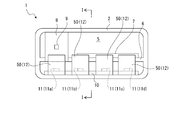
- It is a schematic front view of the lamp for a motorcycle shown with the cover removed.
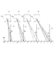
- It is a conceptual diagram which shows the irradiation state of the light emitted from the 2nd light source.
- It is schematic cross-sectional view which shows the example which the 1st light source and the 2nd light source are mounted on one substrate.
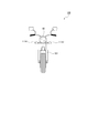
- It is a schematic front view which shows another structure of the lamp for a motorcycle with a cover removed. It is a front view which shows a motorcycle.
- the two-wheeled vehicle lamp 1 is used as a turn signal lamp, and is attached to, for example, both left and right ends at the front end of the vehicle body.
- the two-wheeled vehicle lamp 1 may be attached and arranged at both left and right ends of the rear end of the vehicle body.
- the two-wheeled vehicle lamp 1 includes a lamp housing 2 having a recess opened in the front and a cover 3 that closes the opening of the lamp housing 2 (see FIG. 1).
- the lamp housing 2 and the cover 3 constitute a lamp outer housing 4.
- the internal space of the lamp outer casing 4 is formed as a lamp chamber 5.
- the lamp housing 2 is provided with an arrangement plate portion 6 facing in the vertical direction at a position that partitions the lamp chamber 5 vertically (see FIGS. 1 and 2).
- a control circuit 7 is arranged on the upper surface of the arrangement plate portion 6. The control circuit 7 is connected to a power supply circuit (not shown).
- the first substrate 8 is arranged in the light chamber 5.
- the first substrate 8 faces in the front-rear direction, and for example, the lower end portion is attached to the front surface of the arrangement plate portion 6 and is arranged at a position closer to one end in the left-right direction of the light chamber 5.
- a first light source 9 is mounted on the front surface of the first substrate 8.
- the first light source 9 for example, an LED (Light Emitting Diode) is used.
- the light emitted from the first light source 9 is transmitted through the cover 3 and is emitted toward the front.
- the motorcycle lamp 1 is attached to the rear end of the vehicle body, the light emitted from the first light source 9 of the motorcycle lamp 1 attached to the rear end is emitted toward the rear.
- the turning on and off of the first light source 9 is controlled by the control circuit 7 via the first substrate 8.
- a second substrate 10 is arranged below the first substrate 8 in the light chamber 5.
- the second substrate 10 is formed in a horizontally long shape facing in the vertical direction.
- a plurality of second light sources 11, 11, ... are mounted side by side on the upper surface of the second substrate 10.
- the second light sources 11, 11, ... For example, LEDs are used.
- the second light sources 11, 11, ... are controlled to be turned on and off by the control circuit 7 via the second substrate 10.
- the second light sources 11, 11, ... Are provided as a first light emitting unit 11a, a second light emitting unit 11b, a third light emitting unit 11c, and a fourth light emitting unit 11d in this order in the left-right direction.
- the motorcycle lamp 1 is provided with, for example, four second light sources 11, but at least three second light sources 11 may be provided.
- Reflectors 12, 12, ... As optical control members 50, 50, ... Are arranged in front of the second substrate 10 in the light chamber 5.
- the same number of reflectors 12, 12, ... As the second light sources 11, 11, ... are arranged at positions corresponding to the second light sources 11, 11, ....
- the reflectors 12, 12, ... May be connected in the left-right direction and provided as one optical control member 50.
- the second light sources 11, 11, ... are turned on with a time lag in the order in which they are lined up, so that the so-called sequential point-off state is set, and the second light sources 11, 11, ...
- the irradiation angle of the emitted light with respect to the road surface 100 is made different by the reflection control of the reflectors 12, 12, ....
- the first light emitting unit 11a, the second light emitting unit 11b, the third light emitting unit 11c, and the fourth light emitting unit 11d are lit in order, and first, only the first light emitting unit 11a is lit.
- the second light emitting unit 11b is lit, the first light emitting unit 11a is turned on, and when the third light emitting unit 11c is lit, the first light emitting unit 11a and the second light emitting unit 11b are turned on.
- the fourth light emitting unit 11d is lit, the first light emitting unit 11a, the second light emitting unit 11b, and the third light emitting unit 11c are turned on.
- the first light emitting unit 11a and the second light emitting unit 11a and the second light emitting unit are emitted.
- the unit 11b, the third light emitting unit 11c, and the fourth light emitting unit 11d are turned off at the same time.
- the first light emitting unit 11a, the second light emitting unit 11b, the third light emitting unit 11c, and the fourth light emitting unit 11d are repeatedly turned on and off in the above order.
- the irradiation angle with respect to the road surface 100 is set to increase in order in the first light emitting unit 11a, the second light emitting unit 11b, the third light emitting unit 11c, and the fourth light emitting unit 11d (see FIG. 3). That is, the irradiation angle with respect to the vertical axis P is ⁇ , the irradiation angle of the light emitted from the first light emitting unit 11a with respect to the road surface 100 is ⁇ 1, and the irradiation angle of the light emitted from the second light emitting unit 11b with respect to the road surface 100.
- the irradiation angle of the light emitted from the third light emitting unit 11c with respect to the road surface 100 is ⁇ 3
- the irradiation angle of the light emitted from the fourth light emitting unit 11d with respect to the road surface 100 is ⁇ 4, then ⁇ 1 ⁇ 2. ⁇ 3 ⁇ 4.
- the first light source 9 is turned on at the same time as the first light emitting unit 11a is turned on, and the first light source 9 is turned off at the first light emitting unit 11a and the second light emitting unit 11a. This is performed at the same time when the 11b, the third light emitting unit 11c, and the fourth light emitting unit 11d are turned off.
- the second light sources 11, 11, ... Are lit with a time lag in the order in which they are arranged.
- the irradiation angle of the light emitted from the second light sources 11, 11, ... And controlled by the light control members 50, 50, ... With respect to the road surface 100 is the second light source 11, 11, ....
- the light control members 50, 50, ... are controlled so as to increase in the order of arrangement.
- the road surface 100 is irradiated so that the irradiation angle increases with a time difference in the order in which the lights emitted from the second light sources 11, 11, ... Are arranged, the light flows on the road surface 100 in one direction. It is irradiated and the visibility can be further improved.
- first light source 9 is turned on and off at the same time as the second light source 11 of the second light sources 11, 11, ....
- the first light source 9 since the first light source 9 is turned on and off in a state having the same functions as the second light sources 11, 11, ..., the irradiation brightness when the second light sources 11, 11, ... Are lit. It is possible to improve the functionality as well as to improve the functionality.
- a reflector 12 that reflects light is provided as an optical control member 50.
- the light emitted from the second light sources 11, 11, ... Is reflected by the reflector and irradiates the road surface 100, so that the positions and orientations of the second light sources 11, 11, ... Are free.
- the degree is increased, and after improving the degree of freedom in design, light can be reliably irradiated to a desired position on the road surface 100.
- the first light source 9 is mounted on the first substrate 8 and the second light sources 11, 11, ... Are mounted on the second substrate 10, but the first light source is shown. It is also possible to have a configuration in which 9 and the second light sources 11, 11, ... Are mounted on one substrate 13 (see FIG. 4).
- the substrate 13 faces in the front-rear direction, for example, the first light source 9 is mounted on the upper end side of the substrate 13, and the second light sources 11, 11, ... Are mounted side by side on the lower end side of the substrate 13.
- the first light source 9 and the second light sources 11, 11, ... are mounted, respectively. Since it is not necessary to use a separate substrate, it is possible to reduce the manufacturing cost by reducing the number of parts in the two-wheeled vehicle lamp 1.
- the inner lens is used as the optical control members 50, 50, .... 14, 14, ... May be used (see FIG. 5).
- the inner lens 14 has an incident surface 14a, an inner reflecting surface 14b, and an emitting surface 14c.
- the light emitted from the second light source 11 is incident from the incident surface 14a to be parallel light, reflected by the inner reflecting surface 14b, and parallel to the emitted surface 14c. It is irradiated toward the road surface 100 as light or convergent light.
- the first light source 9 is mounted on the first substrate 8 and the second light source 11, 11, ... May be mounted on the second substrate 10, and the first light source 9 and the second light sources 11, 11, ... May be mounted on the substrate 13. Further, the inner lenses 14, 14, ... May be coupled in the left-right direction and provided as one optical control member 50.
- the inner lenses 14, 14, ... are provided as the light control members 50, 50, ... As described above, the light emitted from the second light sources 11, 11, ... Since the road surface 100 is irradiated under the control of the inner lenses 14, 14, ..., the degree of freedom regarding the position and orientation of the second light sources 11, 11, ... Is increased, and the degree of freedom in design is improved. It is possible to reliably irradiate the light at a desired position on the road surface 100.
- the flexible printed wiring board 15 is provided in place of the second substrate 10 or the substrate 13. It is also possible to set it to (see FIG. 6). In this case, the flexible printed wiring board 15 is attached to the mounting plate 16 in a state in which the orientation of each part is different, and the second light sources 11, 11, ... Are attached to the flexible printed wiring board 15 in a state in which the light emitting directions are different. It is also possible to make the irradiation angle with respect to the road surface 100 different by mounting the reflectors 14, 14, ... In the orientations corresponding to the directions of the second light sources 11, 11, ... is there.
- the flexible printed wiring board 15 can be bent to freely set the direction of the light emitted from the second light sources 11, 11, .... This makes it possible to improve the degree of freedom in design.
- the first light source 9 is mounted on the first substrate 8 and the second light sources 11, 11, ... Are mounted on the flexible printed wiring board 15.
- the first light source 9 and the second light sources 11, 11, ... May be mounted on the flexible printed wiring board 15.
- the first light source 9 is turned on at the same time as the first light emitting unit 11a of the second light sources 11, 11, ..., But the first light source 9 is the second light source. It may be turned on at the same time as any of the light sources 11, 11, ... Further, the first light source 9 may be turned on with a time lag from the second light sources 11, 11, ..., For example, the first light emitting unit 11a may be turned on first.
- the motorcycle lamp 1A having a different configuration from that of the motorcycle lamp 1 will be described below (see FIG. 7).
- the two-wheeled vehicle lamp 1A shown below is compared with the two-wheeled vehicle lamp 1 because it differs from the two-wheeled vehicle lamp 1 only in that the size of the first substrate and the number of the first light sources are different. Only the different parts will be described in detail, and the other parts will be given the same reference numerals as those given to the same parts in the motorcycle lamp 1 and the description thereof will be omitted.
- a horizontally long first substrate 8A is arranged in the light room 5.
- the first light sources 9, 9, ... are mounted on the front surface of the first substrate 8A at a distance from each other to the left and right.
- the first light sources 9, 9, ... are provided with the same number as the second light sources 11, 11, ...
- the second light sources 11, 11, ... are mounted in the left-right direction. It is mounted in the same position as the position.
- the light emitted from the first light sources 9, 9, ... Is transmitted through the cover 3 and is emitted toward the front.
- the motorcycle lamp 1A is also turned on with a time lag in the order in which the second light sources 11, 11, ... Are arranged, so that the so-called sequential lighting is turned off.
- the first light sources 9, 9, ... Are turned on at the same time as the first light emitting unit 11a is turned on, and the first light sources 9, 9, ... Are turned off first.
- the light emitting unit 11a, the second light emitting unit 11b, the third light emitting unit 11c, and the fourth light emitting unit 11d are turned off at the same time.
- the first light sources 9, 9, ... Are turned on and off at the same time as the second light source 11 of the second light sources 11, 11, .... Therefore, since the first light sources 9, 9, ... Are turned on and off in a state having the same functions as the second light sources 11, 11, ..., the second light sources 11, 11, ... It is possible to improve the irradiation brightness at the time of lighting and to improve the functionality.
- the irradiation brightness can be further improved and the visibility can be improved.
- the first light sources 9, 9, ... May be turned on at the same time as any of the second light sources 11, 11, ..., And the time difference from the second light sources 11, 11, ... May be turned on. Further, one of the first light sources 9, 9, ... And one of the second light sources 11, 11, ... may be turned on at the same time with a time lag.
- the two-wheeled vehicle lamps 1 and 1A configured as described above are arranged on the left and right sides of the headlamp 60 at the front end of the vehicle body 101 of the two-wheeled vehicle 100, for example (see FIG. 8). Since the body 101 of the two-wheeled vehicle 100 is smaller than the body of a four-wheeled vehicle such as an automobile, the size of the two-wheeled vehicle lamps 1 and 1A that function as turn signal lamps tends to be small.
- two-wheeled vehicles usually have a small body size, a small space for mounting two-wheeled vehicle lamps on the body, and the number and arrangement positions of light sources provided on the two-wheeled vehicle lamps are also limited. Easy to do.
- the road surface 100 by irradiating the road surface 100 with the light emitted from the second light sources 11, 11, ... Like the two-wheeled vehicle lamps 1, 1A, the light spread on the road surface 100 can be emitted. Be irradiated. Therefore, even when the size of the two-wheeled vehicle lamps 1 and 1A is small, the light irradiated to the road surface 100 is visually recognized by a pedestrian or a passenger of another vehicle in a wide range of irradiation state so as to flow from one side to the other. It is easy to attract the attention of the viewer, the functionality is improved, and high visibility can be ensured.
- the two-wheeled vehicle lamps 1, 1A are used as turn signal lamps.
- the two-wheeled vehicle lamps 1, 1A are in a sequential light emitting state when, for example, a two-wheeled passenger approaches the vehicle body. It can also be applied as a welcome lamp that is lit.
Landscapes
- Engineering & Computer Science (AREA)
- Mechanical Engineering (AREA)
- General Engineering & Computer Science (AREA)
- Physics & Mathematics (AREA)
- Microelectronics & Electronic Packaging (AREA)
- Optics & Photonics (AREA)
- Lighting Device Outwards From Vehicle And Optical Signal (AREA)
- Non-Portable Lighting Devices Or Systems Thereof (AREA)
Abstract
出射された光が前方又は後方へ向けて照射される第1の光源9と、少なくとも三つが並んで設けられた複数の第2の光源11と、複数の第2の光源からそれぞれ出射された光を路面へ向けて照射するように制御する光制御部材50とを備え、複数の第2の光源において並ぶ順に時間差をもって点灯が行われる。これにより、複数の第2の光源から出射された光が複数の第2の光源において並ぶ順に時間差をもって路面へ向けて照射されるため、路面に照射された光が一方から他方へ流れるように視認され、視認者の注意を惹き易く、機能性が向上し高い被視認性を確保することができる。
Description
本発明は、オートバイ等の二輪車において用いられる二輪車用灯具についての技術分野に関する。
オートバイ等の二輪車においてターンシグナルランプとして用いられる二輪車用灯具には、光を出射する複数の光源が並んで配置され複数の光源の並び方向において時間差を持って順に光源から光が出射される所謂シーケンシャルタイプの二輪車用灯具がある(例えば、特許文献1参照)。
このようなタイプの二輪車用灯具は、複数の光源の並び方向において光が一方から他方へ流れるように視認され、視認者の注意を惹き易く、被視認性及び意匠性の向上を図ることが可能である。
ところで、二輪車は自動車等の四輪車と異なり車体の大きさが小さく、車体において二輪車用灯具が取り付けられるスペースも小さくなり、二輪車用灯具に設けられる光源の数や配置位置も制限され易く、シーケンシャルの機能が十分に発揮されず高い被視認性も確保されない可能性がある。
そこで、本発明は、機能性の向上を図り高い被視認性を確保することを目的とする。
第1に、本発明に係る二輪車用灯具は、出射された光が前方又は後方へ向けて照射される第1の光源と、少なくとも三つが並んで設けられた複数の第2の光源と、前記複数の第2の光源からそれぞれ出射された光を路面へ向けて照射するように制御する光制御部材とを備え、前記複数の第2の光源において並ぶ順に時間差をもって点灯が行われるものである。
これにより、複数の第2の光源から出射された光が複数の第2の光源において並ぶ順に時間差をもって路面へ向けて照射される。
第2に、上記した本発明に係る二輪車用灯具においては、前記複数の第2の光源から出射され前記光制御部材によって制御された光の路面に対する照射角度が、前記複数の第2の光源の並ぶ順に大きくなるように前記光制御部材によって制御されることが望ましい。
これにより、第2の光源からそれぞれ出射された光が並ぶ順に時間差をもって照射角度が大きくなるように路面に照射される。
第3に、上記した本発明に係る二輪車用灯具においては、前記第1の光源が前記複数の第2の光源のうち一つの前記第2の光源と同時に点消灯されることが望ましい。
これにより、第1の光源が第2の光源と同様の機能を有する状態で点消灯される。
第4に、上記した本発明に係る二輪車用灯具においては、光源が搭載される基板が設けられ、前記基板に前記第1の光源と前記複数の第2の光源とが搭載されることが望ましい。
これにより、第1の光源と第2の光源をそれぞれ搭載する各別の基板を必要としない。
第5に、上記した本発明に係る二輪車用灯具においては、前記光制御部材として光を反射するリフレクターが設けられることが望ましい。
これにより、第2の光源から出射された光がそれぞれリフレクターで反射されて路面に照射されるため、第2の光源の位置や向きに関する自由度が高くなる。
本発明によれば、複数の第2の光源から出射された光が複数の第2の光源において並ぶ順に時間差をもって路面へ向けて照射されるため、路面に照射された光が一方から他方へ流れるように視認され、視認者の注意を惹き易く、機能性が向上し高い被視認性を確保することができる。
以下に、本発明二輪車用灯具を実施するための形態について添付図面を参照して説明する。
二輪車用灯具1はターンシグナルランプとして用いられ、例えば、車体の前端部において左右両端部にそれぞれ取り付けられて配置されている。尚、二輪車用灯具1は車体の後端部における左右両端部にもそれぞれ取り付けられて配置されていてもよい。
二輪車用灯具1は前方に開口された凹部を有するランプハウジング2とランプハウジング2の開口を閉塞するカバー3とを備えている(図1参照)。ランプハウジング2とカバー3によって灯具外筐4が構成されている。灯具外筐4の内部空間は灯室5として形成されている。
ランプハウジング2には灯室5を上下に仕切る位置に上下方向を向く配置板部6が設けられている(図1及び図2参照)。配置板部6の上面には制御回路7が配置されている。制御回路7は図示しない電源回路に接続されている。
灯室5には第1の基板8が配置されている。第1の基板8は前後方向を向き、例えば、下端部が配置板部6の前面に取り付けられ、灯室5の左右方向における一端に寄った位置に配置されている。
第1の基板8の前面には第1の光源9が搭載されている。第1の光源9としては、例えば、LED(Light Emitting Diode)が用いられている。第1の光源9から出射された光はカバー3を透過され、前方へ向けて照射される。尚、二輪車用灯具1が車体の後端部に取り付けられている場合には、後端部に取り付けられた二輪車用灯具1の第1の光源9から出射された光は後方へ向けて照射される。第1の光源9は第1の基板8を介して制御回路7によって点消灯が制御される。
灯室5における第1の基板8の下方には第2の基板10が配置されている。第2の基板10は上下方向を向き横長の形状に形成されている。
第2の基板10の上面には複数の第2の光源11、11、・・・が左右に並んで搭載されている。第2の光源11、11、・・・としては、例えば、LEDが用いられている。第2の光源11、11、・・・は第2の基板10を介して制御回路7によって点消灯が制御される。第2の光源11、11、・・・は左右方向において順に第1の発光部11a、第2の発光部11b、第3の発光部11c、第4の発光部11dとして設けられている。
尚、二輪車用灯具1には、例えば、四つの第2の光源11が設けられているが、第2の光源11は少なくとも三つが設けられていればよい。
灯室5における第2の基板10の前方には光制御部材50、50、・・・として、例えば、リフレクター12、12、・・・が配置されている。リフレクター12、12、・・・はそれぞれ第2の光源11、11、・・・と同数が第2の光源11、11、・・・に対応する位置に配置されている。尚、リフレクター12、12、・・・は左右方向において結合され、一つの光制御部材50として設けられていてもよい。
第2の光源11、11、・・・から出射された光はそれぞれリフレクター12、12、・・・で反射されて制御され、カバー3を透過されて下方側へ向かい路面100へ向けて照射される。
二輪車用灯具1においては、第2の光源11、11、・・・において並ぶ順に時間差をもって点灯が行われ所謂シーケンシャルの点消灯状態にされ、また、第2の光源11、11、・・・から出射された光の路面100に対する照射角度がリフレクター12、12、・・・の反射制御によって異なるようにされている。
具体的に、時間差に関しては、第1の発光部11aと第2の発光部11bと第3の発光部11cと第4の発光部11dが順に点灯され、先ず第1の発光部11aのみが点灯され、第2の発光部11bの点灯時には第1の発光部11aが点灯状態にされ、第3の発光部11cの点灯時には第1の発光部11aと第2の発光部11bが点灯状態にされ、第4の発光部11dの点灯時には第1の発光部11aと第2の発光部11bと第3の発光部11cが点灯状態にされる。第1の発光部11aと第2の発光部11bと第3の発光部11cと第4の発光部11dが点灯された後の一定時間経過後には、第1の発光部11aと第2の発光部11bと第3の発光部11cと第4の発光部11dが同時に消灯される。
二輪車用灯具1においては、上記の順の第1の発光部11aと第2の発光部11bと第3の発光部11cと第4の発光部11dの点消灯が繰り返し行われる。
路面100に対する照射角度に関しては、第1の発光部11aと第2の発光部11bと第3の発光部11cと第4の発光部11dにおいて順に大きくなるようにされている(図3参照)。即ち、鉛直軸Pに対する照射角度をθとし、第1の発光部11aから出射された光の路面100に対する照射角度をθ1とし、第2の発光部11bから出射された光の路面100に対する照射角度をθ2とし、第3の発光部11cから出射された光の路面100に対する照射角度をθ3とし、第4の発光部11dから出射された光の路面100に対する照射角度をθ4とすると、θ1<θ2<θ3<θ4にされている。
上記のような光の制御が行われることにより、第2の光源11、11、・・・から時間差をもって出射された光が左右方向において順に路面100に照射され、路面100に対する照射角度の相違により左右方向において順に光が外側に広がる状態で視認される。
また、二輪車用灯具1においては、第1の光源9の点灯が第1の発光部11aの点灯と同時に行われ、第1の光源9の消灯が第1の発光部11aと第2の発光部11bと第3の発光部11cと第4の発光部11dの消灯と同時に行われる。
以上に記載した通り、二輪車用灯具1にあっては、出射された光が前方又は後方へ向けて照射される第1の光源9と、少なくとも三つが並んで設けられた第2の光源11、11、・・・と、第2の光源11、11、・・・からそれぞれ出射された光を路面100へ向けて照射するように制御する光制御部材50、50、・・・とを備え、第2の光源11、11、・・・において並ぶ順に時間差をもって点灯が行われる。
従って、第1の光源9から光が前方又は後方へ向けて照射された上で第2の光源11、11、・・・から出射された光が第2の光源11、11、・・・において並ぶ順に時間差をもって路面100へ向けて照射されるため、路面100に照射された光が一方から他方へ流れるように視認され、視認者の注意を惹き易く、機能性が向上し高い被視認性を確保することができる。
また、第2の光源11、11、・・・から出射され光制御部材50、50、・・・によって制御された光の路面100に対する照射角度が、第2の光源11、11、・・・の並ぶ順に大きくなるように光制御部材50、50、・・・によって制御される。
従って、第2の光源11、11、・・・からそれぞれ出射された光が並ぶ順に時間差をもって照射角度が大きくなるように路面100に照射されるため、路面100に光が一方向において流れるように照射され、一層の被視認性の向上を図ることができる。
さらに、第1の光源9が第2の光源11、11、・・・のうち一つの第2の光源11と同時に点消灯される。
従って、第1の光源9が第2の光源11、11、・・・と同様の機能を有する状態で点消灯されるため、第2の光源11、11、・・・の点灯時における照射輝度の向上を図ることができると共に機能性の向上を図ることができる。
さらにまた、光制御部材50として光を反射するリフレクター12が設けられている。
従って、第2の光源11、11、・・・から出射された光がそれぞれリフレクターで反射されて路面100に照射されるため、第2の光源11、11、・・・の位置や向きに関する自由度が高くなり、設計の自由度の向上を図った上で光を路面100の所望の位置に確実に照射することができる。
上記には、第1の光源9が第1の基板8に搭載され、第2の光源11、11、・・・が第2の基板10に搭載された例を示したが、第1の光源9と第2の光源11、11、・・・が一つの基板13に搭載される構成にすることも可能である(図4参照)。基板13は、例えば、前後方向を向き、基板13の上端側に第1の光源9が搭載され、基板13の下端側に第2の光源11、11、・・・が左右に並んで搭載される。
このように基板13に第1の光源9と第2の光源11、11、・・・が搭載されることにより、第1の光源9と第2の光源11、11、・・・をそれぞれ搭載する各別の基板を必要としないため、二輪車用灯具1における部品点数の削減による製造コストの低減を図ることができる。
また、上記には、光制御部材50、50、・・・としてリフレクター12、12、・・・が用いられた例を示したが、例えば、光制御部材50、50、・・・としてインナーレンズ14、14、・・・が用いられてもよい(図5参照)。インナーレンズ14は入射面14aと内面反射面14bと出射面14cを有している。光制御部材50としてインナーレンズ14が用いられた構成において、第2の光源11から出射された光は入射面14aから入射されて平行光にされ、内面反射面14bで反射され出射面14cから平行光又は収束光として路面100へ向けて照射される。
尚、光制御部材50、50、・・・としてインナーレンズ14、14、・・・が用いられた構成においても、第1の光源9が第1の基板8に搭載され第2の光源11、11、・・・が第2の基板10に搭載されていてもよく、第1の光源9と第2の光源11、11、・・・が基板13に搭載されていてもよい。また、インナーレンズ14、14、・・・は左右方向において結合され、一つの光制御部材50として設けられていてもよい。
上記のように光制御部材50、50、・・・としてインナーレンズ14、14、・・・が設けられた場合には、第2の光源11、11、・・・から出射された光がそれぞれインナーレンズ14、14、・・・で制御されて路面100に照射されるため、第2の光源11、11、・・・の位置や向きに関する自由度が高くなり、設計の自由度の向上を図った上で光を路面100の所望の位置に確実に照射することができる。
尚、光制御部材50、50、・・・としてインナーレンズ14、14、・・・が設けられた場合において、第2の基板10又は基板13に代えてフレキシブルプリント配線板15が設けられた構成にすることも可能である(図6参照)。この場合において、フレキシブルプリント配線板15は取付板16に各部の向きが異なる状態で取り付けられ、第2の光源11、11、・・・は光の出射方向が異なる状態でフレキシブルプリント配線板15に搭載され、リフレクター14、14、・・・が第2の光源11、11、・・・の向きに応じた向きで配置されることにより、路面100に対する照射角度を異なるようにすることも可能である。
このようなフレキシブルプリント配線板15が設けられる構成にすることにより、フレキシブルプリント配線板15を屈曲させて第2の光源11、11、・・・から出射される光の向きを自由に設定することが可能になり、設計の自由度の向上を図ることができる。
尚、フレキシブルプリント配線板15が設けられる構成において、光制御部材50としてインナーレンズ14に代えてリフレクター12を用いることも可能である。
また、フレキシブルプリント配線板15が用いられた構成において、第1の光源9が第1の基板8に搭載され第2の光源11、11、・・・がフレキシブルプリント配線板15に搭載されていてもよく、第1の光源9と第2の光源11、11、・・・がフレキシブルプリント配線板15に搭載されていてもよい。
尚、上記には、第1の光源9が第2の光源11、11、・・・のうち第1の発光部11aと同時に点灯される例を示したが、第1の光源9は第2の光源11、11、・・・の何れと同時に点灯されてもよい。また、第1の光源9は第2の光源11、11、・・・と時間差をもって点灯されてもよく、例えば、第1の発光部11aに先んじて点灯されてもよい。
以下に、二輪車用灯具1とは構成が異なる別の構成の二輪車用灯具1Aについて説明する(図7参照)。
尚、以下に示す二輪車用灯具1Aは、上記した二輪車用灯具1と比較して、第1の基板の大きさと第1の光源の数が異なることのみが相違するため、二輪車用灯具1と比較して異なる部分についてのみ詳細に説明をし、その他の部分については二輪車用灯具1における同様の部分に付した符号と同じ符号を付して説明は省略する。
灯室5には横長の第1の基板8Aが配置されている。第1の基板8Aの前面には第1の光源9、9、・・・が左右に離隔して搭載されている。第1の光源9、9、・・・は、例えば、第2の光源11、11、・・・と同数が設けられ、左右方向において第2の光源11、11、・・・が搭載された位置と同じ位置に搭載されている。第1の光源9、9、・・・からそれぞれ出射された光はカバー3を透過され、前方へ向けて照射される。
二輪車用灯具1Aにおいても、二輪車用灯具1と同様に、第2の光源11、11、・・・において並ぶ順に時間差をもって点灯が行われ所謂シーケンシャルの点消灯状態にされる。
二輪車用灯具1Aにおいては、第1の光源9、9、・・・の点灯が第1の発光部11aの点灯と同時に行われ、第1の光源9、9、・・・の消灯が第1の発光部11aと第2の発光部11bと第3の発光部11cと第4の発光部11dの消灯と同時に行われる。
このように二輪車用灯具1Aにおいても、第1の光源9、9、・・・が第2の光源11、11、・・・のうち一つの第2の光源11と同時に点消灯される。従って、第1の光源9、9、・・・が第2の光源11、11、・・・と同様の機能を有する状態で点消灯されるため、第2の光源11、11、・・・の点灯時における照射輝度の向上を図ることができると共に機能性の向上を図ることができる。
特に、二輪車用灯具1Aにおいては、複数の第1の光源9が設けられているため、照射輝度の一層の向上が図られ、被視認性の向上を図ることができる。
尚、第1の光源9、9、・・・は第2の光源11、11、・・・の何れと同時に点灯されてもよく、また、第2の光源11、11、・・・と時間差をもって点灯されてもよい。さらに、第1の光源9、9、・・・と第2の光源11、11、・・・のそれぞれ一つずつが同時に時間差をもって点灯されてもよい。
上記のように構成された二輪車用灯具1、1Aは、例えば、二輪車100における車体101の前端部においてヘッドランプ60の左右両側に配置される(図8参照)。二輪車100の車体101は自動車等の四輪車の車体より小さいため、ターンシグナルランプとして機能する二輪車用灯具1、1Aも大きさが小さくなり易い。
このように、通常、二輪車は自動車等の四輪車と異なり車体の大きさが小さく、車体において二輪車用灯具が取り付けられるスペースも小さくなり、二輪車用灯具に設けられる光源の数や配置位置も制限され易い。
しかしながら、二輪車用灯具1、1Aのように、第2の光源11、11、・・・からそれぞれ出射された光を路面100へ向けて照射する構成にすることにより、路面100に広がった光が照射される。従って、二輪車用灯具1、1Aの大きさが小さい場合においても、歩行者や他の車輌の搭乗者において路面100に照射された光が一方から他方へ流れるように広範囲の照射状態で視認され、視認者の注意を惹き易く、機能性が向上し高い被視認性を確保することができる。
上記には、二輪車用灯具1、1Aがターンシグナルランプとして用いられた例を示したが、二輪車用灯具1、1Aは、例えば、二輪の搭乗者が車体に近付いたときにシーケンシャルの発光状態で点灯が行われるウエルカムランプとしても適用することが可能である。
1…二輪車用灯具、9…第1の光源、11…第2の光源、12…リフレクター、13…基板、光制御部材…50
Claims (5)
- 出射された光が前方又は後方へ向けて照射される第1の光源と、
少なくとも三つが並んで設けられた複数の第2の光源と、
前記複数の第2の光源からそれぞれ出射された光を路面へ向けて照射するように制御する光制御部材とを備え、
前記複数の第2の光源において並ぶ順に時間差をもって点灯が行われる
二輪車用灯具。 - 前記複数の第2の光源から出射され前記光制御部材によって制御された光の路面に対する照射角度が、前記複数の第2の光源の並ぶ順に大きくなるように前記光制御部材によって制御される
請求項1に記載の二輪車用灯具。 - 前記第1の光源が前記複数の第2の光源のうち一つの前記第2の光源と同時に点消灯される
請求項1又は請求項2に記載の二輪車用灯具。 - 光源が搭載される基板が設けられ、
前記基板に前記第1の光源と前記複数の第2の光源とが搭載された
請求項1、請求項2又は請求項3に記載の二輪車用灯具。 - 前記光制御部材として光を反射するリフレクターが設けられた
請求項1、請求項2、請求項3又は請求項4に記載の二輪車用灯具。
Priority Applications (1)
| Application Number | Priority Date | Filing Date | Title |
|---|---|---|---|
| JP2021524790A JPWO2020246333A1 (ja) | 2019-06-04 | 2020-05-27 |
Applications Claiming Priority (2)
| Application Number | Priority Date | Filing Date | Title |
|---|---|---|---|
| JP2019104261 | 2019-06-04 | ||
| JP2019-104261 | 2019-06-04 |
Publications (1)
| Publication Number | Publication Date |
|---|---|
| WO2020246333A1 true WO2020246333A1 (ja) | 2020-12-10 |
Family
ID=73652500
Family Applications (1)
| Application Number | Title | Priority Date | Filing Date |
|---|---|---|---|
| PCT/JP2020/020881 Ceased WO2020246333A1 (ja) | 2019-06-04 | 2020-05-27 | 二輪車用灯具 |
Country Status (2)
| Country | Link |
|---|---|
| JP (1) | JPWO2020246333A1 (ja) |
| WO (1) | WO2020246333A1 (ja) |
Citations (9)
| Publication number | Priority date | Publication date | Assignee | Title |
|---|---|---|---|---|
| JPS4735770U (ja) * | 1971-05-07 | 1972-12-20 | ||
| JP2008155767A (ja) * | 2006-12-22 | 2008-07-10 | Tatsuzo Atsugi | 車両用転向方向表示装置 |
| JP2010030470A (ja) * | 2008-07-29 | 2010-02-12 | Honda Motor Co Ltd | 自動二輪車 |
| JP2010055929A (ja) * | 2008-08-28 | 2010-03-11 | Honda Motor Co Ltd | 尾灯装置 |
| CN103029771A (zh) * | 2012-12-05 | 2013-04-10 | 深圳市欧克蓝科技有限公司 | 无线指示灯系统及其控制方法 |
| JP2015189280A (ja) * | 2014-03-27 | 2015-11-02 | スタンレー電気株式会社 | ライセンスランプを備えた車両用灯具 |
| JP2017074820A (ja) * | 2015-10-13 | 2017-04-20 | スズキ株式会社 | 車両の報知システム |
| JP2017218133A (ja) * | 2016-06-10 | 2017-12-14 | スズキ株式会社 | ポジション照明装置 |
| WO2019044404A1 (ja) * | 2017-09-01 | 2019-03-07 | 株式会社小糸製作所 | 車両用照明システム、車両システム、灯具ユニットおよび車両用灯具 |
-
2020
- 2020-05-27 WO PCT/JP2020/020881 patent/WO2020246333A1/ja not_active Ceased
- 2020-05-27 JP JP2021524790A patent/JPWO2020246333A1/ja active Pending
Patent Citations (9)
| Publication number | Priority date | Publication date | Assignee | Title |
|---|---|---|---|---|
| JPS4735770U (ja) * | 1971-05-07 | 1972-12-20 | ||
| JP2008155767A (ja) * | 2006-12-22 | 2008-07-10 | Tatsuzo Atsugi | 車両用転向方向表示装置 |
| JP2010030470A (ja) * | 2008-07-29 | 2010-02-12 | Honda Motor Co Ltd | 自動二輪車 |
| JP2010055929A (ja) * | 2008-08-28 | 2010-03-11 | Honda Motor Co Ltd | 尾灯装置 |
| CN103029771A (zh) * | 2012-12-05 | 2013-04-10 | 深圳市欧克蓝科技有限公司 | 无线指示灯系统及其控制方法 |
| JP2015189280A (ja) * | 2014-03-27 | 2015-11-02 | スタンレー電気株式会社 | ライセンスランプを備えた車両用灯具 |
| JP2017074820A (ja) * | 2015-10-13 | 2017-04-20 | スズキ株式会社 | 車両の報知システム |
| JP2017218133A (ja) * | 2016-06-10 | 2017-12-14 | スズキ株式会社 | ポジション照明装置 |
| WO2019044404A1 (ja) * | 2017-09-01 | 2019-03-07 | 株式会社小糸製作所 | 車両用照明システム、車両システム、灯具ユニットおよび車両用灯具 |
Also Published As
| Publication number | Publication date |
|---|---|
| JPWO2020246333A1 (ja) | 2020-12-10 |
Similar Documents
| Publication | Publication Date | Title |
|---|---|---|
| US11054105B2 (en) | Lamp and vehicle having same | |
| CN102192460B (zh) | 具有光源和至少两个用于分布光线的光学元件的机动车前照灯 | |
| US9739438B2 (en) | Vehicle lamp | |
| US8496365B2 (en) | Articulating lamp assembly for a vehicle | |
| JP5363235B2 (ja) | 車両用灯具 | |
| CN108375048B (zh) | 车载灯具 | |
| JP2006269271A (ja) | 車両用灯具 | |
| US9248776B2 (en) | Vehicular light unit with multiple light sources | |
| CN207378735U (zh) | 包括矩阵静态弯曲灯光学系统的前照灯 | |
| CN207080934U (zh) | 车载灯具 | |
| CN220338283U (zh) | 车辆用灯具 | |
| JP5941383B2 (ja) | 車両用灯具 | |
| CN103017056A (zh) | 车辆用灯具 | |
| EP2075501B1 (en) | Vehicle headlamp | |
| JP4735424B2 (ja) | 車両用灯具 | |
| JP2020098726A (ja) | 鞍乗型車両用灯具 | |
| CN107435882B (zh) | 照明装置 | |
| WO2019124188A1 (ja) | 車両用前照灯 | |
| JP4752626B2 (ja) | 車両用灯具 | |
| JP2020098724A (ja) | 車両用灯具 | |
| KR101106250B1 (ko) | 일체형 쉴드 구비 차량용 시그널 램프 | |
| WO2020246333A1 (ja) | 二輪車用灯具 | |
| CN108916810B (zh) | 用于车灯的光学模块的光反射器、车灯和机动车辆 | |
| TWM654621U (zh) | 車用光源切換裝置 | |
| JP4565653B2 (ja) | 車両用led灯具 |
Legal Events
| Date | Code | Title | Description |
|---|---|---|---|
| 121 | Ep: the epo has been informed by wipo that ep was designated in this application |
Ref document number: 20819091 Country of ref document: EP Kind code of ref document: A1 |
|
| ENP | Entry into the national phase |
Ref document number: 2021524790 Country of ref document: JP Kind code of ref document: A |
|
| NENP | Non-entry into the national phase |
Ref country code: DE |
|
| 122 | Ep: pct application non-entry in european phase |
Ref document number: 20819091 Country of ref document: EP Kind code of ref document: A1 |