WO2020246282A1 - 無人車両の制御システム及び無人車両の制御方法 - Google Patents
無人車両の制御システム及び無人車両の制御方法 Download PDFInfo
- Publication number
- WO2020246282A1 WO2020246282A1 PCT/JP2020/020459 JP2020020459W WO2020246282A1 WO 2020246282 A1 WO2020246282 A1 WO 2020246282A1 JP 2020020459 W JP2020020459 W JP 2020020459W WO 2020246282 A1 WO2020246282 A1 WO 2020246282A1
- Authority
- WO
- WIPO (PCT)
- Prior art keywords
- blinker
- unmanned vehicle
- data
- travel
- course data
- Prior art date
- Legal status (The legal status is an assumption and is not a legal conclusion. Google has not performed a legal analysis and makes no representation as to the accuracy of the status listed.)
- Ceased
Links
Images

Classifications
-
- G—PHYSICS
- G05—CONTROLLING; REGULATING
- G05D—SYSTEMS FOR CONTROLLING OR REGULATING NON-ELECTRIC VARIABLES
- G05D1/00—Control of position, course, altitude or attitude of land, water, air or space vehicles, e.g. using automatic pilots
- G05D1/0055—Control of position, course, altitude or attitude of land, water, air or space vehicles, e.g. using automatic pilots with safety arrangements
-
- B—PERFORMING OPERATIONS; TRANSPORTING
- B60—VEHICLES IN GENERAL
- B60Q—ARRANGEMENT OF SIGNALLING OR LIGHTING DEVICES, THE MOUNTING OR SUPPORTING THEREOF OR CIRCUITS THEREFOR, FOR VEHICLES IN GENERAL
- B60Q1/00—Arrangement of optical signalling or lighting devices, the mounting or supporting thereof or circuits therefor
- B60Q1/26—Arrangement of optical signalling or lighting devices, the mounting or supporting thereof or circuits therefor the devices being primarily intended to indicate the vehicle, or parts thereof, or to give signals, to other traffic
- B60Q1/34—Arrangement of optical signalling or lighting devices, the mounting or supporting thereof or circuits therefor the devices being primarily intended to indicate the vehicle, or parts thereof, or to give signals, to other traffic for indicating change of drive direction
- B60Q1/346—Arrangement of optical signalling or lighting devices, the mounting or supporting thereof or circuits therefor the devices being primarily intended to indicate the vehicle, or parts thereof, or to give signals, to other traffic for indicating change of drive direction with automatic actuation
-
- B—PERFORMING OPERATIONS; TRANSPORTING
- B60—VEHICLES IN GENERAL
- B60Q—ARRANGEMENT OF SIGNALLING OR LIGHTING DEVICES, THE MOUNTING OR SUPPORTING THEREOF OR CIRCUITS THEREFOR, FOR VEHICLES IN GENERAL
- B60Q1/00—Arrangement of optical signalling or lighting devices, the mounting or supporting thereof or circuits therefor
- B60Q1/26—Arrangement of optical signalling or lighting devices, the mounting or supporting thereof or circuits therefor the devices being primarily intended to indicate the vehicle, or parts thereof, or to give signals, to other traffic
- B60Q1/34—Arrangement of optical signalling or lighting devices, the mounting or supporting thereof or circuits therefor the devices being primarily intended to indicate the vehicle, or parts thereof, or to give signals, to other traffic for indicating change of drive direction
- B60Q1/40—Arrangement of optical signalling or lighting devices, the mounting or supporting thereof or circuits therefor the devices being primarily intended to indicate the vehicle, or parts thereof, or to give signals, to other traffic for indicating change of drive direction having mechanical, electric or electronic automatic return to inoperative position
-
- G—PHYSICS
- G05—CONTROLLING; REGULATING
- G05D—SYSTEMS FOR CONTROLLING OR REGULATING NON-ELECTRIC VARIABLES
- G05D1/00—Control of position, course, altitude or attitude of land, water, air or space vehicles, e.g. using automatic pilots
- G05D1/0055—Control of position, course, altitude or attitude of land, water, air or space vehicles, e.g. using automatic pilots with safety arrangements
- G05D1/0061—Control of position, course, altitude or attitude of land, water, air or space vehicles, e.g. using automatic pilots with safety arrangements for transition from automatic pilot to manual pilot and vice versa
-
- G—PHYSICS
- G05—CONTROLLING; REGULATING
- G05D—SYSTEMS FOR CONTROLLING OR REGULATING NON-ELECTRIC VARIABLES
- G05D1/00—Control of position, course, altitude or attitude of land, water, air or space vehicles, e.g. using automatic pilots
- G05D1/02—Control of position or course in two dimensions
- G05D1/021—Control of position or course in two dimensions specially adapted to land vehicles
- G05D1/0212—Control of position or course in two dimensions specially adapted to land vehicles with means for defining a desired trajectory
-
- B—PERFORMING OPERATIONS; TRANSPORTING
- B60—VEHICLES IN GENERAL
- B60Q—ARRANGEMENT OF SIGNALLING OR LIGHTING DEVICES, THE MOUNTING OR SUPPORTING THEREOF OR CIRCUITS THEREFOR, FOR VEHICLES IN GENERAL
- B60Q2800/00—Features related to particular types of vehicles not otherwise provided for
- B60Q2800/10—Autonomous vehicles
Definitions
- This disclosure relates to an unmanned vehicle control system and an unmanned vehicle control method.
- Unmanned vehicles may be used at wide-area work sites such as mines.
- the unmanned vehicle can be operated in either a manual mode in which the vehicle is operated by the driver's driving operation or an automatic mode in which the vehicle is operated unmanned without the driving operation of the driver.
- unmanned vehicles At the work site, not only unmanned vehicles but also manned vehicles operate.
- the unmanned vehicle When the unmanned vehicle is provided with a blinker, the worker on the manned vehicle can recognize the traveling direction of the unmanned vehicle. On the other hand, if the blinker does not operate correctly, the worker in the manned vehicle cannot correctly recognize the traveling direction of the unmanned vehicle.
- the present disclosure includes a traveling course data acquisition unit that acquires traveling course data including blinker data that controls a blinker provided in an unmanned vehicle, and an operation data acquisition unit that acquires operation data of a blinker operating device provided in the unmanned vehicle.
- a traveling course data acquisition unit that acquires traveling course data including blinker data that controls a blinker provided in an unmanned vehicle
- an operation data acquisition unit that acquires operation data of a blinker operating device provided in the unmanned vehicle.
- the blinkers of an unmanned vehicle can be operated correctly.
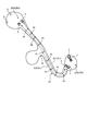
- FIG. 1 is a diagram schematically showing an example of a control system, an unmanned vehicle, and a manned vehicle according to the embodiment.
- FIG. 2 is a diagram schematically showing an example of a work site according to the embodiment.
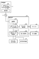
- FIG. 3 is a functional block diagram showing an example of the management device and the control device according to the embodiment.
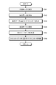
- FIG. 4 is a flowchart showing an example of the control method of the unmanned vehicle according to the embodiment.
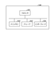
- FIG. 5 is a block diagram showing an example of a computer system.
- FIG. 1 is a diagram schematically showing an example of a control system 1, an unmanned vehicle 2, and a manned vehicle 9 according to the present embodiment.
- the unmanned vehicle 2 refers to a vehicle that can be operated unmanned without being driven by a driver.
- the unmanned vehicle 2 operates at the work site.
- the control system 1 includes a management device 3 and a communication system 4.
- the management device 3 includes a computer system and is installed in, for example, a mine control facility 5.
- the communication system 4 carries out communication between the management device 3 and the unmanned vehicle 2.
- the wireless communication device 6 is connected to the management device 3.
- the communication system 4 includes a wireless communication device 6.
- the management device 3 and the unmanned vehicle 2 wirelessly communicate with each other via the communication system 4.
- the unmanned vehicle 2 operates at the work site based on the travel course data from the management device 3.
- the unmanned vehicle 2 includes a blinker 20, a traveling device 21, a vehicle body 22 supported by the traveling device 21, a dump body 23 supported by the vehicle body 22, and a control device 30.
- the blinker 20 is a direction indicator that displays the traveling direction of the unmanned vehicle 2.
- the blinkers 20 are arranged at the front portion and the rear portion of the vehicle body 22, respectively. By operating the blinker 20, the traveling direction of the unmanned vehicle 2 is notified to the surroundings.
- the blinker 20 includes a blinker lamp.
- the operation of the blinker 20 includes lighting or blinking of the blinker lamp. Stopping the operation of the blinker 20 includes turning off the blinker lamp.
- the blinker 20 includes a right blinker lamp that lights up or blinks when the unmanned vehicle 2 turns right, and a left blinker lamp that lights up or blinks when the unmanned vehicle 2 turns left.
- the right turn signal lamp is arranged on the right side of the vehicle body 22.
- the left turn signal lamp is arranged on the left side of the vehicle body 22. Further, the blinker 20 can be turned on by a hazard in which the right blinker lamp and the left blinker lamp are lit or blink at the same time.
- the traveling device 21 includes a driving device 24 for driving the traveling device 21, a braking device 25 for braking the traveling device 21, a steering device 26 for adjusting the traveling direction, and wheels 27.
- the unmanned vehicle 2 self-propells due to the rotation of the wheels 27.
- the wheel 27 includes a front wheel 27F and a rear wheel 27R. Tires are mounted on the wheels 27.
- the drive device 24 generates a driving force for accelerating the unmanned vehicle 2.
- the drive device 24 includes an internal combustion engine such as a diesel engine.
- the drive device 24 may include an electric motor.
- the power generated by the drive device 24 is transmitted to the rear wheels 27R.
- the braking device 25 generates a braking force for decelerating or stopping the unmanned vehicle 2.
- the steering device 26 can adjust the traveling direction of the unmanned vehicle 2.
- the traveling direction of the unmanned vehicle 2 includes the direction of the front portion of the vehicle body 22.
- the steering device 26 adjusts the traveling direction of the unmanned vehicle 2 by steering the front wheels 27F.
- the control device 30 is arranged in the unmanned vehicle 2.
- the control device 30 can communicate with the management device 3 existing outside the unmanned vehicle 2.
- the control device 30 outputs an accelerator command for operating the drive device 24, a brake command for operating the brake device 25, and a steering command for operating the steering device 26.
- the drive device 24 generates a driving force for accelerating the unmanned vehicle 2 based on the accelerator command output from the control device 30.
- the brake device 25 generates a braking force for decelerating the unmanned vehicle 2 based on the brake command output from the control device 30.
- the steering device 26 generates a force for changing the direction of the front wheels 27F in order to drive the unmanned vehicle 2 straight or turn based on the steering command output from the control device 30.
- the unmanned vehicle 2 includes a position detecting device 28 that detects the position of the unmanned vehicle 2.
- the position of the unmanned vehicle 2 is detected using a global navigation satellite system (GNSS: Global Navigation Satellite System).
- the Global Navigation Satellite System includes the Global Positioning System (GPS).
- GPS Global Positioning System
- the global navigation satellite system detects the absolute position of the unmanned vehicle 2 defined by the coordinate data of latitude, longitude, and altitude.
- the position of the unmanned vehicle 2 defined in the global coordinate system is detected by the global navigation satellite system.
- the global coordinate system is a coordinate system fixed to the earth.
- the position detection device 28 includes a GNSS receiver and detects the absolute position (coordinates) of the unmanned vehicle 2.
- the unmanned vehicle 2 is equipped with a wireless communication device 29.
- Communication system 4 includes a wireless communication device 29.
- the wireless communication device 29 can wirelessly communicate with the management device 3.
- the manned vehicle 9 is operated by the driving operation of the operator.
- the manned vehicle 9 has a driver's cab on which the worker board.
- the manned vehicle 9 includes a control device 90 and a wireless communication device 91.
- the communication system 4 includes a wireless communication device 91.
- the wireless communication device 91 can wirelessly communicate with the management device 3.
- FIG. 2 is a diagram schematically showing an example of a work site according to the present embodiment.
- the work site is a mine or a quarry
- the unmanned vehicle 2 is a dump truck that travels on the work site and transports cargo.
- a mine is a place or place of business where minerals are mined.
- Examples of the cargo carried to the unmanned vehicle 2 include ore or earth and sand excavated in a mine or a quarry.
- the unmanned vehicle 2 travels at least a part of the mine workshop PA and the runway HL leading to the workshop PA.
- the workplace PA includes at least one of a loading site LPA and a lumberyard DPA.
- the road HL includes the intersection IS.
- Loading area LPA refers to the area where the loading work for loading the unmanned vehicle 2 is carried out.
- a loading machine 7 such as a hydraulic excavator operates.
- the lumber yard DPA is an area where the discharge work is carried out in which the cargo is discharged from the unmanned vehicle 2.
- a crusher 8 is provided in the lumber yard DPA.
- the target travel path Cr is set in the travel path HL and the workplace PA.
- the unmanned vehicle 2 travels on the travel path HL according to the target travel path Cr.
- the target travel path Cr includes the target travel path Cr1 and the target travel path Cr2.
- the unmanned vehicle 2 travels from the loading yard DPA to the loading yard LPA according to the target traveling route Cr1 and travels from the loading yard LPA to the loading yard DPA according to the target traveling route Cr2.
- FIG. 3 is a functional block diagram showing an example of the management device 3, the control device 30, and the control device 90 according to the present embodiment.
- the control device 30 can communicate with the management device 3 via the communication system 4.
- the management device 3 has a communication unit 3A and a running course data generation unit 3B.
- the communication unit 3A receives the data transmitted from the control device 30 via the communication system 4. Further, the communication unit 3A transmits data to the control device 30 via the communication system 4.
- the travel course data generation unit 3B generates travel course data including the target travel route Cr of the unmanned vehicle 2.
- the running course data includes a plurality of point PIs set at intervals.
- the target travel path Cr is defined by a line connecting a plurality of point PIs.
- the target traveling speed and the target traveling direction of the unmanned vehicle 2 are set for each of the plurality of point PIs.
- the traveling course data includes the blinker data for controlling the blinker 20.
- the blinker data is set for each of the plurality of point PIs.
- the blinker data indicates the operating conditions of the blinker 20 when the unmanned vehicle 2 passes the point PI.
- the blinker data includes operation start data for starting the operation of the right blinker lamp, operation start data for starting the operation of the left blinker lamp, operation stop data for stopping the operation of the right blinker lamp, and left blinker lamp. Includes operation stop data for stopping the operation of.
- the travel course data generation unit 3B outputs the generated travel course data to the communication unit 3A.
- the communication unit 3A transmits the travel course data to the control device 30 of the unmanned vehicle 2.
- the unmanned vehicle 2 operates unmanned based on the driving course data regardless of the driving operation of the driver in the driver's cab of the unmanned vehicle 2 and the manual mode. It can operate in either automatic mode. That is, the unmanned vehicle 2 is switched between the automatic mode and the manual mode.
- the control device 30 is connected to each of the blinker operation device 31 and the travel operation device 32.
- Each of the blinker operating device 31 and the traveling operating device 32 is provided in the unmanned vehicle 2.
- the unmanned vehicle 2 is provided with a driver's cab on which the driver boarded in the manual mode.
- Each of the blinker operating device 31 and the traveling operating device 32 is arranged in the driver's cab of the unmanned vehicle 2.
- the blinker operating device 31 is operated to operate and stop the blinker 20.
- the driver or worker who has boarded the driver's cab of the unmanned vehicle 2 can operate the blinker operating device 31.
- the blinker operating device 31 includes a blinker lever capable of operating and stopping the blinker 20.
- the blinker operation device 31 includes a hazard switch that lights the blinker 20 as a hazard. In the manual mode, the driver or the operator can operate the blinker operating device 31 to operate the blinker 20.
- the traveling operation device 32 is operated for operating and stopping the operation of the traveling device 21.
- the driver or worker who has boarded the driver's cab of the unmanned vehicle 2 can operate the traveling operation device 32.
- the travel control device 32 includes an accelerator pedal for arbitrating the output of the drive device 24, a brake pedal for operating the brake device 25, and a steering wheel for operating the steering device 26. In the manual mode, the driver or the operator can operate the traveling operation device 32 to operate the traveling device 21.
- the control device 30 includes a communication unit 30A, a travel course data acquisition unit 30B, an operation data acquisition unit 30C, a blinker control unit 30D, and a travel control unit 30E.
- the communication unit 30A transmits data to the management device 3 via the communication system 4. Further, the communication unit 30A receives the data transmitted from the management device 3 via the communication system 4.
- the traveling course data acquisition unit 30B acquires the traveling course data including the blinker data for controlling the blinker 20 provided in the unmanned vehicle 2 transmitted from the management device 3.
- the operation data acquisition unit 30C acquires the operation data of the blinker operation device 31 provided in the unmanned vehicle 2. Further, the operation data acquisition unit 30C acquires the operation data of the traveling operation device 32 provided in the unmanned vehicle 2.
- the blinker control unit 30D controls the blinker 20 of the unmanned vehicle 2.
- the blinker control unit 30D controls the operation of the blinker 20.
- the blinker control unit 30D controls the blinker 20 based on the blinker data included in the travel course data.
- the blinker control unit 30D controls the blinker 20 based on the blinker data included in the travel course data acquired by the travel course data acquisition unit 30B.
- the blinker control unit 30D controls the blinker 20 based on the operation data generated by operating the blinker operation device 31.
- the blinker control unit 30D converts the blinker data into the blinker data. Based on this, the blinker 20 is controlled.
- the blinker control unit 30D does not depend on the operation data of the blinker operation device 31, but the travel course data acquisition unit.
- the blinker 20 is controlled based on the blinker data acquired by the 30B. That is, in the automatic mode, when the traveling course data acquisition unit 30B acquires the blinker data and the operation data acquisition unit 30C acquires the operation data of the blinker operation device 31, the blinker control unit 30D does not depend on the operation data.
- the blinker 20 is controlled based on the data.
- the blinker operating device 31 may be operated.
- the unmanned vehicle 2 when the unmanned vehicle 2 is driven in the automatic mode for the first time at a work site, the unmanned vehicle 2 may be driven in the automatic mode while the driver is on the unmanned vehicle 2.
- the driver may accidentally touch the blinker operating device 31 and the blinker operating device 31 may move. ..
- the blinker operating device 31 may move due to the vibration of the vehicle body 22. In this way, even when the blinker operation device 31 is operated in the automatic mode, the blinker control unit 30D controls the blinker 20 based on the blinker data transmitted from the management device 3.
- the blinker control unit 30D uses the operation data of the blinker operation device 31. Instead, the blinker 20 is controlled based on the blinker data transmitted from the management device 3.
- the blinker control unit 30D manages more than the operation data of the blinker operation device 31.
- the blinker 20 may be controlled by giving priority to the blinker data transmitted from the device 3.
- the travel control unit 30E controls the travel device 21 of the unmanned vehicle 2.
- the travel control unit 30E controls the travel of the unmanned vehicle 2.
- the travel control unit 30E controls the travel of the unmanned vehicle 2 based on the operation data generated by the operation of the travel operation device 32.
- the traveling control unit 30E controls the traveling of the unmanned vehicle 2 based on the traveling course data acquired by the traveling course data acquisition unit 30B.
- FIG. 4 is a flowchart showing an example of a control method for the unmanned vehicle 2 according to the present embodiment.
- the unmanned vehicle 2 is set to the manual mode (step SA1).
- the blinker operating device 31 may be operated in the manual mode. For example, when the unmanned vehicle 2 is moved to the parking lot for maintenance, the driver may move the unmanned vehicle 2 to the parking lot while operating the blinker operating device 31 and the traveling operating device 32.
- the operation data acquisition unit 30C acquires the operation data of the blinker operation device 31 (step SA2).
- the blinker control unit 30D controls the blinker 20 based on the operation data acquired by the operation data acquisition unit 30C (step SA3).
- Unmanned vehicle 2 is set to automatic mode (step SA4).
- the travel course data generation unit 3B generates travel course data including blinker data.
- the communication unit 3A transmits the generated travel course data to the control device 30 of the unmanned vehicle 2 via the communication system 4.
- the travel course data acquisition unit 30B acquires the travel course data (step SA5).
- the unmanned vehicle 2 set in the automatic mode starts operation based on the traveling course data.
- the travel control unit 30E controls the travel device 21 so that the unmanned vehicle 2 travels according to the target travel path Cr defined by the travel course data.
- the blinker control unit 30D controls the blinker 20 based on the blinker data included in the travel course data (step SA6).
- the blinker control unit 30D In the automatic mode, if the blinker operation device 31 is operated and the operation data acquisition unit 30C acquires the operation data, but the unmanned vehicle 2 is operating based on the travel course data, the blinker control unit 30D The blinker 20 is controlled based on the blinker data. That is, in the automatic mode, when both the operation data of the blinker operation device 31 and the blinker data are acquired by the control device 30, the blinker control unit 30D uses the blinker data instead of the operation data of the blinker operation device 31. Based on this, the blinker 20 is controlled.
- the control device 30 displays both the operation data of the blinker operation device 31 and the blinker data from the management device 3.
- the blinker 20 is controlled based on the blinker data transmitted from the management device 3.
- the control device 30 can correctly operate the blinker 20 of the unmanned vehicle 2.
- the blinker operating device 31 may be operated for some reason. If the blinker 20 is controlled based on the operation data of the blinker operating device 31, the blinker 20 may not operate correctly. For example, when the traveling course data acquisition unit 30B acquires the traveling course data for turning the unmanned vehicle 2 to the left while the blinker operating device 31 is operated to operate the right blinker lamp, the blinker operating device 31 is in the automatic mode. If the operation data of the above is prioritized, the right turn signal lamp will be activated while the unmanned vehicle 2 is turning left. As described above, if the blinker 20 does not operate correctly in the automatic mode, the worker on the manned vehicle 9 or another worker existing at the work site cannot correctly recognize the traveling direction of the unmanned vehicle 2. there is a possibility.
- the blinker 20 when the unmanned vehicle 2 operates based on the traveling course data, even if the blinker operating device 31 is operated, the blinker 20 is controlled based on the blinker data included in the traveling course data. To. Since the blinker 20 is controlled based on the blinker data conforming to the target travel path Cr, the blinker 20 can be correctly operated so as to conform to the target travel path Cr.
- FIG. 5 is a block diagram showing an example of the computer system 1000.
- the computer system 1000 includes a processor 1001 such as a CPU (Central Processing Unit), a main memory 1002 including a non-volatile memory such as a ROM (Read Only Memory) and a volatile memory such as a RAM (Random Access Memory). It has a storage 1003 and an interface 1004 including an input / output circuit.
- the functions of the management device 3 and the functions of the control device 30 described above are stored in the storage 1003 as a program.
- the processor 1001 reads the program from the storage 1003, expands it into the main memory 1002, and executes the above-described processing according to the program.
- the program may be distributed to the computer system 1000 via the network.
- the computer system 1000 acquires the traveling course data including the blinker data for controlling the blinker 20 provided in the unmanned vehicle 2 and the operation data of the blinker operating device 31 provided in the unmanned vehicle 2 according to the above-described embodiment.
- the unmanned vehicle 2 operates based on the traveling course data
- the blinker 20 can be controlled based on the blinker data.
- the unmanned vehicle 2 is switched between the automatic mode and the manual mode.
- the unmanned vehicle 2 does not have to be switched between the automatic mode and the manual mode.
- the manned vehicle 9 is operated as the unmanned vehicle 2
- the blinker operating device 31 when the operation data is acquired, the blinker control unit 30D controls the blinker 20 based on the blinker data acquired by the traveling course data acquisition unit 30B.
- At least a part of the functions of the control device 30 of the unmanned vehicle 2 may be provided in the management device 3, or at least a part of the functions of the management device 3 is provided in the control device 30. May be good.
- the traveling course data is generated in the management device 3, and the unmanned vehicle 2 travels according to the traveling course data transmitted from the management device 3.
- the control device 30 of the unmanned vehicle 2 may generate travel course data. That is, the control device 30 may have a traveling course data generation unit. Further, each of the management device 3 and the control device 30 may have a travel course data generation unit.
- the unmanned vehicle 2 is a dump truck which is a kind of transport vehicle.
- the unmanned vehicle 2 may be a work machine including a work machine such as a hydraulic excavator or a bulldozer.
- operation data acquisition unit 30D ... blinker control unit, 30E ... Travel control unit, 31 ... Turn signal operation device, 32 ... Travel operation device, 90 ... Control device, 91 ... Wireless communication device, Cr ... Target travel route, Cr1 ... Target travel route, Cr2 ... Target travel route, HL ... Travel Road, PA ... workshop, DPA ... earth removal site, LPA ... loading site.
Landscapes
- Engineering & Computer Science (AREA)
- Aviation & Aerospace Engineering (AREA)
- Radar, Positioning & Navigation (AREA)
- Remote Sensing (AREA)
- Physics & Mathematics (AREA)
- General Physics & Mathematics (AREA)
- Automation & Control Theory (AREA)
- Mechanical Engineering (AREA)
- Control Of Position, Course, Altitude, Or Attitude Of Moving Bodies (AREA)
- Lighting Device Outwards From Vehicle And Optical Signal (AREA)
- Electric Propulsion And Braking For Vehicles (AREA)
Abstract
Description
図1は、本実施形態に係る管制システム1、無人車両2、及び有人車両9の一例を模式的に示す図である。無人車両2とは、運転者による運転操作によらずに、無人で稼動することができる車両をいう。無人車両2は、作業現場において稼働する。
無人車両2は、管理装置3からの走行コースデータに基づいて、作業現場において稼働する。無人車両2は、ウインカー20と、走行装置21と、走行装置21に支持される車両本体22と、車両本体22に支持されるダンプボディ23と、制御装置30とを備える。
有人車両9は、作業者の運転操作により稼働する。有人車両9は、作業者が搭乗する運転室を有する。また、有人車両9は、制御装置90と、無線通信機91とを備える。通信システム4は、無線通信機91を含む。無線通信機91は、管理装置3と無線通信可能である。
図2は、本実施形態に係る作業現場の一例を模式的に示す図である。本実施形態において、作業現場は鉱山又は採石場であり、無人車両2は作業現場を走行して積荷を運搬するダンプトラックである。鉱山とは、鉱物を採掘する場所又は事業所をいう。無人車両2に運搬される積荷として、鉱山又は採石場において掘削された鉱石又は土砂が例示される。
図3は、本実施形態に係る管理装置3、制御装置30、及び制御装置90の一例を示す機能ブロック図である。制御装置30は、通信システム4を介して管理装置3と通信可能である。
図4は、本実施形態に係る無人車両2の制御方法の一例を示すフローチャートである。例えば無人車両2のメンテナンス等において、無人車両2が手動モードに設定される(ステップSA1)。
以上説明したように、本実施形態によれば、無人車両2が走行コースデータに基づいて動作する場合において、制御装置30がウインカー操作装置31の操作データ及び管理装置3からのウインカーデータの両方を取得した場合、管理装置3から送信されたウインカーデータに基づいて、ウインカー20を制御する。これにより、制御装置30は、無人車両2のウインカー20を正しく作動させることができる。
図5は、コンピュータシステム1000の一例を示すブロック図である。上述の管理装置3、制御装置30、及び制御装置90のそれぞれは、コンピュータシステム1000を含む。コンピュータシステム1000は、CPU(Central Processing Unit)のようなプロセッサ1001と、ROM(Read Only Memory)のような不揮発性メモリ及びRAM(Random Access Memory)のような揮発性メモリを含むメインメモリ1002と、ストレージ1003と、入出力回路を含むインターフェース1004とを有する。上述の管理装置3の機能及び制御装置30の機能は、プログラムとしてストレージ1003に記憶されている。プロセッサ1001は、プログラムをストレージ1003から読み出してメインメモリ1002に展開し、プログラムに従って上述の処理を実行する。なお、プログラムは、ネットワークを介してコンピュータシステム1000に配信されてもよい。
上述の実施形態においては、無人車両2が自動モードと手動モードとに切換えられることとした。無人車両2は自動モードと手動モードとに切換えられなくてもよい。例えば、有人車両9を無人車両2として動作させる場合など、自動モードと手動モードとが存在しない無人車両2においても、無人車両2が走行コースデータに基づいて動作するときに、ウインカー操作装置31の操作データが取得された場合、ウインカー制御部30Dは、走行コースデータ取得部30Bにより取得されたウインカーデータに基づいて、ウインカー20を制御する。
Claims (3)
- 無人車両に設けられるウインカーを制御するウインカーデータを含む走行コースデータを取得する走行コースデータ取得部と、
前記無人車両に設けられるウインカー操作装置の操作データを取得する操作データ取得部と、
前記無人車両が前記走行コースデータに基づいて動作するときに、前記操作データ取得部により前記操作データが取得された場合、前記走行コースデータ取得部により取得された前記ウインカーデータに基づいて前記ウインカーを制御するウインカー制御部と、を備える、
無人車両の制御システム。 - 前記走行コースデータに基づいて前記無人車両の走行を制御する走行制御部を備える、
請求項1に記載の無人車両の制御システム。 - 無人車両に設けられるウインカーを制御するウインカーデータを含む走行コースデータを取得することと、
前記無人車両に設けられるウインカー操作装置の操作データを取得することと、
前記無人車両が前記走行コースデータに基づいて動作するときに、前記操作データが取得された場合、前記ウインカーデータに基づいて前記ウインカーを制御することと、を含む、
無人車両の制御方法。
Priority Applications (4)
| Application Number | Priority Date | Filing Date | Title |
|---|---|---|---|
| AU2020287517A AU2020287517A1 (en) | 2019-06-03 | 2020-05-25 | System of controlling unmanned vehicle and method of controlling unmanned vehicle |
| CA3140491A CA3140491A1 (en) | 2019-06-03 | 2020-05-25 | System of controlling unmanned vehicle and method of controlling unmanned vehicle |
| US17/607,117 US20220212597A1 (en) | 2019-06-03 | 2020-05-25 | System of controlling unmanned vehicle and method of controlling unmanned vehicle |
| AU2023233137A AU2023233137B2 (en) | 2019-06-03 | 2023-09-21 | System of controlling unmanned vehicle and method of controlling unmanned vehicle |
Applications Claiming Priority (2)
| Application Number | Priority Date | Filing Date | Title |
|---|---|---|---|
| JP2019103966A JP7329363B2 (ja) | 2019-06-03 | 2019-06-03 | 無人車両の制御システム及び無人車両の制御方法 |
| JP2019-103966 | 2019-06-03 |
Publications (1)
| Publication Number | Publication Date |
|---|---|
| WO2020246282A1 true WO2020246282A1 (ja) | 2020-12-10 |
Family
ID=73649626
Family Applications (1)
| Application Number | Title | Priority Date | Filing Date |
|---|---|---|---|
| PCT/JP2020/020459 Ceased WO2020246282A1 (ja) | 2019-06-03 | 2020-05-25 | 無人車両の制御システム及び無人車両の制御方法 |
Country Status (5)
| Country | Link |
|---|---|
| US (1) | US20220212597A1 (ja) |
| JP (1) | JP7329363B2 (ja) |
| AU (2) | AU2020287517A1 (ja) |
| CA (1) | CA3140491A1 (ja) |
| WO (1) | WO2020246282A1 (ja) |
Families Citing this family (1)
| Publication number | Priority date | Publication date | Assignee | Title |
|---|---|---|---|---|
| DE102022002451B3 (de) * | 2022-07-05 | 2023-06-29 | Mercedes-Benz Group AG | Verfahren zum automatischen Ansteuern eines Fahrtrichtungsanzeigers und Fahrzeug |
Citations (2)
| Publication number | Priority date | Publication date | Assignee | Title |
|---|---|---|---|---|
| JP2017109705A (ja) * | 2015-12-18 | 2017-06-22 | 株式会社小松製作所 | 作業機械の管理システム、作業機械の制御システム、及び作業機械 |
| JP2018043549A (ja) * | 2016-09-12 | 2018-03-22 | トヨタ自動車株式会社 | 自動運転システム |
Family Cites Families (9)
| Publication number | Priority date | Publication date | Assignee | Title |
|---|---|---|---|---|
| JP4561722B2 (ja) | 2006-10-04 | 2010-10-13 | アイシン・エィ・ダブリュ株式会社 | 運転支援装置 |
| JP6187182B2 (ja) * | 2013-11-19 | 2017-08-30 | 日産自動車株式会社 | 車両用運転支援装置及び車両用運転支援方法 |
| JP6712906B2 (ja) | 2016-05-31 | 2020-06-24 | 株式会社小松製作所 | 作業機械の管理装置、作業機械、及び作業機械の管理システム |
| US10406972B2 (en) * | 2017-02-24 | 2019-09-10 | Tesla, Inc. | Vehicle technologies for automated turn signaling |
| JP6608095B2 (ja) * | 2017-07-05 | 2019-11-20 | 三菱電機株式会社 | 表示システムおよび表示方法 |
| US10514695B2 (en) * | 2017-11-15 | 2019-12-24 | Denso International America, Inc. | Driver assisting system |
| CN107740448A (zh) * | 2017-11-30 | 2018-02-27 | 南京工业大学 | 一种无人自动化挖掘机智能施工系统 |
| JP7353747B2 (ja) * | 2018-01-12 | 2023-10-02 | キヤノン株式会社 | 情報処理装置、システム、方法、およびプログラム |
| US12117833B2 (en) * | 2019-05-09 | 2024-10-15 | Gm Cruise Holdings Llc | Client control for an autonomous vehicle ridesharing service |
-
2019
- 2019-06-03 JP JP2019103966A patent/JP7329363B2/ja active Active
-
2020
- 2020-05-25 CA CA3140491A patent/CA3140491A1/en active Pending
- 2020-05-25 AU AU2020287517A patent/AU2020287517A1/en not_active Abandoned
- 2020-05-25 US US17/607,117 patent/US20220212597A1/en not_active Abandoned
- 2020-05-25 WO PCT/JP2020/020459 patent/WO2020246282A1/ja not_active Ceased
-
2023
- 2023-09-21 AU AU2023233137A patent/AU2023233137B2/en active Active
Patent Citations (2)
| Publication number | Priority date | Publication date | Assignee | Title |
|---|---|---|---|---|
| JP2017109705A (ja) * | 2015-12-18 | 2017-06-22 | 株式会社小松製作所 | 作業機械の管理システム、作業機械の制御システム、及び作業機械 |
| JP2018043549A (ja) * | 2016-09-12 | 2018-03-22 | トヨタ自動車株式会社 | 自動運転システム |
Also Published As
| Publication number | Publication date |
|---|---|
| AU2020287517A1 (en) | 2021-11-25 |
| US20220212597A1 (en) | 2022-07-07 |
| CA3140491A1 (en) | 2020-12-10 |
| JP7329363B2 (ja) | 2023-08-18 |
| JP2020197946A (ja) | 2020-12-10 |
| AU2023233137B2 (en) | 2025-04-10 |
| AU2023233137A1 (en) | 2023-10-12 |
Similar Documents
| Publication | Publication Date | Title |
|---|---|---|
| AU2017275215B2 (en) | Work machine management device, work machine, and work machine management system | |
| JP6783064B2 (ja) | 作業機械の管理システム及び作業機械の管理方法 | |
| AU2019275632B2 (en) | Work machine management system, work machine control system, and work machine | |
| AU2023233137B2 (en) | System of controlling unmanned vehicle and method of controlling unmanned vehicle | |
| WO2020246319A1 (ja) | 作業現場の管理システム及び作業現場の管理方法 | |
| AU2023214367B2 (en) | Work site management system and work site management method | |
| AU2023204001A1 (en) | Control system of unmanned vehicle and control method of unmanned vehicle | |
| WO2020189651A1 (ja) | 作業現場の管理システム及び作業現場の管理方法 | |
| JP2022011448A (ja) | 無人車両の制御システム、無人車両、及び無人車両の制御方法 | |
| WO2017168894A1 (ja) | 作業機械の管理システム |
Legal Events
| Date | Code | Title | Description |
|---|---|---|---|
| 121 | Ep: the epo has been informed by wipo that ep was designated in this application |
Ref document number: 20818047 Country of ref document: EP Kind code of ref document: A1 |
|
| ENP | Entry into the national phase |
Ref document number: 3140491 Country of ref document: CA |
|
| ENP | Entry into the national phase |
Ref document number: 2020287517 Country of ref document: AU Date of ref document: 20200525 Kind code of ref document: A |
|
| NENP | Non-entry into the national phase |
Ref country code: DE |
|
| 122 | Ep: pct application non-entry in european phase |
Ref document number: 20818047 Country of ref document: EP Kind code of ref document: A1 |