WO2020241540A1 - システムの制御方法、及びシステム - Google Patents
システムの制御方法、及びシステム Download PDFInfo
- Publication number
- WO2020241540A1 WO2020241540A1 PCT/JP2020/020449 JP2020020449W WO2020241540A1 WO 2020241540 A1 WO2020241540 A1 WO 2020241540A1 JP 2020020449 W JP2020020449 W JP 2020020449W WO 2020241540 A1 WO2020241540 A1 WO 2020241540A1
- Authority
- WO
- WIPO (PCT)
- Prior art keywords
- work
- image data
- imaging
- image pickup
- learning model
- Prior art date
- Legal status (The legal status is an assumption and is not a legal conclusion. Google has not performed a legal analysis and makes no representation as to the accuracy of the status listed.)
- Ceased
Links
Images


Classifications
-
- G—PHYSICS
- G06—COMPUTING OR CALCULATING; COUNTING
- G06T—IMAGE DATA PROCESSING OR GENERATION, IN GENERAL
- G06T7/00—Image analysis
- G06T7/0002—Inspection of images, e.g. flaw detection
- G06T7/0004—Industrial image inspection
- G06T7/001—Industrial image inspection using an image reference approach
-
- G—PHYSICS
- G06—COMPUTING OR CALCULATING; COUNTING
- G06T—IMAGE DATA PROCESSING OR GENERATION, IN GENERAL
- G06T7/00—Image analysis
- G06T7/0002—Inspection of images, e.g. flaw detection
- G06T7/0004—Industrial image inspection
-
- B—PERFORMING OPERATIONS; TRANSPORTING
- B25—HAND TOOLS; PORTABLE POWER-DRIVEN TOOLS; MANIPULATORS
- B25J—MANIPULATORS; CHAMBERS PROVIDED WITH MANIPULATION DEVICES
- B25J9/00—Program-controlled manipulators
- B25J9/16—Program controls
- B25J9/1694—Program controls characterised by use of sensors other than normal servo-feedback from position, speed or acceleration sensors, perception control, multi-sensor controlled systems, sensor fusion
- B25J9/1697—Vision controlled systems
-
- G—PHYSICS
- G01—MEASURING; TESTING
- G01N—INVESTIGATING OR ANALYSING MATERIALS BY DETERMINING THEIR CHEMICAL OR PHYSICAL PROPERTIES
- G01N21/00—Investigating or analysing materials by the use of optical means, i.e. using sub-millimetre waves, infrared, visible or ultraviolet light
- G01N21/84—Systems specially adapted for particular applications
- G01N21/88—Investigating the presence of flaws or contamination
- G01N21/89—Investigating the presence of flaws or contamination in moving material, e.g. running paper or textiles
-
- G—PHYSICS
- G01—MEASURING; TESTING
- G01N—INVESTIGATING OR ANALYSING MATERIALS BY DETERMINING THEIR CHEMICAL OR PHYSICAL PROPERTIES
- G01N21/00—Investigating or analysing materials by the use of optical means, i.e. using sub-millimetre waves, infrared, visible or ultraviolet light
- G01N21/84—Systems specially adapted for particular applications
- G01N21/88—Investigating the presence of flaws or contamination
- G01N21/93—Detection standards; Calibrating baseline adjustment, drift correction
-
- G—PHYSICS
- G05—CONTROLLING; REGULATING
- G05B—CONTROL OR REGULATING SYSTEMS IN GENERAL; FUNCTIONAL ELEMENTS OF SUCH SYSTEMS; MONITORING OR TESTING ARRANGEMENTS FOR SUCH SYSTEMS OR ELEMENTS
- G05B13/00—Adaptive control systems, i.e. systems automatically adjusting themselves to have a performance which is optimum according to some preassigned criterion
- G05B13/02—Adaptive control systems, i.e. systems automatically adjusting themselves to have a performance which is optimum according to some preassigned criterion electric
- G05B13/0265—Adaptive control systems, i.e. systems automatically adjusting themselves to have a performance which is optimum according to some preassigned criterion electric the criterion being a learning criterion
-
- G—PHYSICS
- G05—CONTROLLING; REGULATING
- G05B—CONTROL OR REGULATING SYSTEMS IN GENERAL; FUNCTIONAL ELEMENTS OF SUCH SYSTEMS; MONITORING OR TESTING ARRANGEMENTS FOR SUCH SYSTEMS OR ELEMENTS
- G05B19/00—Program-control systems
- G05B19/02—Program-control systems electric
- G05B19/418—Total factory control, i.e. centrally controlling a plurality of machines, e.g. direct or distributed numerical control [DNC], flexible manufacturing systems [FMS], integrated manufacturing systems [IMS] or computer integrated manufacturing [CIM]
- G05B19/41875—Total factory control, i.e. centrally controlling a plurality of machines, e.g. direct or distributed numerical control [DNC], flexible manufacturing systems [FMS], integrated manufacturing systems [IMS] or computer integrated manufacturing [CIM] characterised by quality surveillance of production
-
- G—PHYSICS
- G06—COMPUTING OR CALCULATING; COUNTING
- G06N—COMPUTING ARRANGEMENTS BASED ON SPECIFIC COMPUTATIONAL MODELS
- G06N20/00—Machine learning
-
- G—PHYSICS
- G06—COMPUTING OR CALCULATING; COUNTING
- G06T—IMAGE DATA PROCESSING OR GENERATION, IN GENERAL
- G06T1/00—General purpose image data processing
- G06T1/20—Processor architectures; Processor configuration, e.g. pipelining
-
- H—ELECTRICITY
- H04—ELECTRIC COMMUNICATION TECHNIQUE
- H04N—PICTORIAL COMMUNICATION, e.g. TELEVISION
- H04N23/00—Cameras or camera modules comprising electronic image sensors; Control thereof
- H04N23/60—Control of cameras or camera modules
-
- H—ELECTRICITY
- H04—ELECTRIC COMMUNICATION TECHNIQUE
- H04N—PICTORIAL COMMUNICATION, e.g. TELEVISION
- H04N23/00—Cameras or camera modules comprising electronic image sensors; Control thereof
- H04N23/70—Circuitry for compensating brightness variation in the scene
- H04N23/73—Circuitry for compensating brightness variation in the scene by influencing the exposure time
-
- G—PHYSICS
- G05—CONTROLLING; REGULATING
- G05B—CONTROL OR REGULATING SYSTEMS IN GENERAL; FUNCTIONAL ELEMENTS OF SUCH SYSTEMS; MONITORING OR TESTING ARRANGEMENTS FOR SUCH SYSTEMS OR ELEMENTS
- G05B2219/00—Program-control systems
- G05B2219/30—Nc systems
- G05B2219/32—Operator till task planning
- G05B2219/32193—Ann, neural base quality management
-
- G—PHYSICS
- G06—COMPUTING OR CALCULATING; COUNTING
- G06T—IMAGE DATA PROCESSING OR GENERATION, IN GENERAL
- G06T2207/00—Indexing scheme for image analysis or image enhancement
- G06T2207/10—Image acquisition modality
- G06T2207/10141—Special mode during image acquisition
- G06T2207/10144—Varying exposure
-
- G—PHYSICS
- G06—COMPUTING OR CALCULATING; COUNTING
- G06T—IMAGE DATA PROCESSING OR GENERATION, IN GENERAL
- G06T2207/00—Indexing scheme for image analysis or image enhancement
- G06T2207/20—Special algorithmic details
- G06T2207/20081—Training; Learning
-
- G—PHYSICS
- G06—COMPUTING OR CALCULATING; COUNTING
- G06T—IMAGE DATA PROCESSING OR GENERATION, IN GENERAL
- G06T2207/00—Indexing scheme for image analysis or image enhancement
- G06T2207/20—Special algorithmic details
- G06T2207/20084—Artificial neural networks [ANN]
-
- G—PHYSICS
- G06—COMPUTING OR CALCULATING; COUNTING
- G06T—IMAGE DATA PROCESSING OR GENERATION, IN GENERAL
- G06T2207/00—Indexing scheme for image analysis or image enhancement
- G06T2207/30—Subject of image; Context of image processing
- G06T2207/30108—Industrial image inspection
- G06T2207/30164—Workpiece; Machine component
Definitions
- the present invention relates to a system control method and a system.
- Patent Document 1 discloses an inspection system in which an imaging device images a work and the image data obtained by the imaging device is input to a processing device configured by artificial intelligence to perform defect inspection.
- a trained model is generated. For example, in the visual inspection of workpieces produced in a factory, the workpieces flowing on the production line may be inspected, but since the workpieces are moving at high speed, if the shutter speed is too slow, it will be displayed in the image data. Work may be shaken. If a trained model is created based on such image data, the recognition accuracy of the work by artificial intelligence may decrease. The recognition accuracy of the work is, for example, the accuracy of determining the presence or absence of defects. On the other hand, it is conceivable to increase the shutter speed to obtain image data, but there are cases where the shooting location is limited, such as when a predetermined amount of light is required. Patent Document 1 does not study the decrease in the recognition accuracy of the work due to the imaging conditions when obtaining the image data for generating such a trained model.
- One aspect of the system control method is a system control method including an image pickup device and a processing device having a learning model into which image data captured by the image pickup device is input.
- the first work is different from the first work while changing the relative position with respect to the image pickup device by the step of performing machine learning by the learning model and the image pickup device set to the first image pickup condition.
- the step of obtaining the second image data by imaging the second work, and the second image data is input to the trained learning model, and the second image data is related to the second work.
- the relative position with respect to the imaging device is determined by the step of performing the estimation and the imaging device set to the second imaging condition different from the first imaging condition when the estimation accuracy is lower than a predetermined value.
- a step of obtaining the third image data by imaging the third work while changing it, and a step of performing machine learning by the learning model using the third image data as teacher data are performed.
- One aspect of the system according to the present invention is a system including an imaging device and a processing device having a learning model in which image data captured by the imaging device is input, and the processing device is a first imaging device.
- Machine learning by the learning model is performed using the first image data obtained by imaging the first work while changing the relative position with respect to the image pickup device by the image pickup device set in the condition as teacher data.
- the image data of the above is input to the trained learning model, estimation of the second work is performed from the second image data, and when the accuracy of the estimation is lower than a predetermined value, the first imaging is performed.
- the third image data obtained by imaging the third work while changing the relative position with respect to the imaging device by the imaging device set to the second imaging condition different from the condition is used as the teacher data. Then, the process of performing machine learning by the learning model is performed.
- the accuracy of estimation regarding the work in the image data can be improved.
- FIG. 1 shows the basic configuration of an inspection system as an example of the system.
- the system according to this embodiment can be adopted in various systems in addition to the inspection system. Examples of various systems include a system for specifying whether or not a specific image data exists, an automatic distribution system for a distribution center, and the like.
- the sensor 10 is, for example, a sensor for detecting a work moving at high speed on a production line, and for example, an infrared sensor is used.
- a signal is output from the sensor 10 to the trigger generation circuit 20.
- the trigger generation circuit 20 generates an imaging trigger signal based on the signal from the sensor 10 (FIG. 2: S2).
- the trigger generation circuit 20 is composed of logic circuits such as FPGA (Field Programmable gate array) and ASIC (Application Specific Integrated Circuit), for example.
- the trigger generation circuit 20 performs hardware processing on the signal input from the sensor 10, and the hardware-processed trigger signal for imaging is transmitted to the imaging device 30. Then, the imaging device 30 images the work (FIG. 2: S3).
- the trigger generation circuit 20 is composed of a logic circuit, and parallel processing is performed by hardware processing. Then, the signal from the trigger generation circuit 20 is input to the image pickup apparatus 30 without going through software processing. Therefore, useless delay is less likely to occur as compared with software processing that performs sequential processing. It is preferable that the trigger signal is transmitted from the trigger generation circuit 20 to the image pickup apparatus 30 by wire.
- the image pickup device 30 is input with a lens unit, an image pickup element, a signal processing unit that processes a signal output from the image pickup element, an output unit that outputs image data generated by the signal processing unit, and a trigger signal. It has an input unit.
- the imaging device 30 starts imaging.
- the lens unit is provided so as to be removable from the image pickup apparatus, and an appropriate lens unit can be selected according to the size of the object and the shooting scene.
- the signal processing unit generates image data from the signal output from the image sensor.
- the output unit outputs the image data generated by the signal processing unit.
- the image sensor is an element in which the photoelectric conversion unit is arranged in an array, for example, a CMOS sensor.
- the image sensor may be a rolling shutter type image sensor in which the start and end of the exposure period are different for each line, or a global electronic shutter type image sensor in which the start and end of the exposure period are simultaneous for all lines.
- the image data output from the image pickup apparatus 30 is input to the processing apparatus 40 to estimate the image data (FIG. 2: S4).
- the processing device 40 estimates the object of the image data.
- the estimation of the object of the image data is processed according to the use of the system.
- a visual inspection process for determining whether or not the work to be imaged has a defect will be described.
- the specifying process corresponds to the estimation process.
- the process of discriminating by the size of the work corresponds to the process of estimation. It is preferable that the image data is transmitted from the image pickup apparatus 30 to the processing apparatus 40 by wire.
- the processing device 40 has a trained model, and uses the trained model to determine whether or not the work is defective. Since the GPU (Graphics Processing Unit) 42 can perform efficient calculations by processing more data in parallel, the GPU 42 is used when learning is performed multiple times using a learning model such as deep learning. It is effective to perform processing. Therefore, in the present embodiment, the GPU 42 is used in addition to the CPU 41 for the processing in the processing device 40. Specifically, when a learning program including a learning model is executed, learning is performed by the CPU 41 and the GPU 42 cooperating to perform calculations. The processing of the processing device 40 may be performed only by the CPU 41 or the GPU 42.
- Each of the CPU 41 and the GPU 42 has a memory, and the image data output from the image pickup apparatus is held in these memories.
- the image data at the same time is held in the memories of the CPU 41 and the GPU 42.
- the processing device 40 may have a memory different from the memory of the CPU 41 and the main memory of the GPU 42. In this case, the image data is held in the main memory. Then, if necessary, the image data held in the main memory is written to the memory of the CPU 41 and the memory of the GPU 42.
- the GPU 42 accesses the image data held in the memory and processes the image data in parallel.
- the GPU 42 uses the trained model to determine whether or not the work is defective.
- the GPU 42 is more suitable than the CPU 41 for performing a large amount of routine calculation processing, and the GPU 42 can quickly perform a process of determining the presence or absence of defects from the image data of the work.
- the processing device 40 determines whether or not there is a defect in the image data area based on the image data acquired by the image pickup device 30 (FIG. 2: S5).
- the determination result performed by the processing device 40 is output to the PLC (Programmable Logic Controller) 50, and in the case of the final determination result that the work is defective, the PLC 50 inputs a signal for motion control to the robot 60.
- the robot 60 switches the movement operation of the work and moves the work determined to be defective from the production line (FIG. 2: S6).
- High-speed signal transmission is not required when the determination result is output from the processing device 40 to the PLC 50. Therefore, signal transfer can be performed using a general-purpose standard such as Ethernet or wired or wireless.
- FIG. 3 is a diagram for explaining an AI for determining a defect of a work performed by the GPU 42 of the processing device 40.
- FIG. 3A is a conceptual diagram of the learning phase.
- the learning model 420 has a defect determination algorithm and inputs teacher data to the learning model 420.
- the teacher data is image data obtained by flowing a non-defective work, a work including a first defect, a work including a second defect different from the first defect, and the like into a production line. That is, as teacher data, L non-defective images 411, M first defective images 412, N second defective images 413, and the like are input.
- the trained model 430 is a trained model 420 that has been trained by AI so as to be a more accurate algorithm.
- the nearest neighbor method may be used.
- it may be deep learning in which features and coupling weighting coefficients for learning are generated by themselves using a neural network.
- a CNN model Convolutional Neural Network Model
- a model for deep learning may be used as a model for deep learning.
- FIG. 3B is a conceptual diagram of the estimation phase.
- the defect presence / absence determination result 450 is output.
- the process using the trained model 430 is executed by the GPU 42.
- the work image 440 is image data captured by the image pickup apparatus 30 by flowing the work on the production line.
- the work used to generate the teacher data is image data obtained by imaging a non-defective work, a work containing the first defect, a work containing the second defect, and the like.
- the shutter speed is changed between the first imaging condition and the second imaging condition. Specifically, the process of creating a trained model using image data obtained by photographing the above-mentioned work at a certain shutter speed as teacher data is performed until the estimation accuracy of the trained model becomes equal to or higher than a predetermined accuracy. It is repeated while changing. For example, as shown in FIG. 4B, if the shutter speed is too slow, defects in the work will be blurred, and the presence or absence of defects cannot be determined. Therefore, even if these image data are input to the learning model as a teacher model, it is difficult to recognize the presence or absence of defects in the constructed trained model. On the other hand, if the shutter speed is set too high, it is possible to determine the defect as shown in FIG.
- a trained model is generated using image data obtained by imaging these workpieces as teacher data under certain imaging conditions.
- the accuracy of the trained model is determined and the accuracy is lower than a predetermined value
- the trained model is generated by using the image data captured by changing the imaging conditions as the teacher data.
- the teacher data is generated and the accuracy is repeatedly determined until the accuracy becomes the predetermined value or more, and the trained model whose accuracy is the predetermined value or more is used for the inspection system. Thereby, the accuracy of the estimation processing regarding the work of the image data can be improved.
- the method of generating the trained model 430 will be specifically described below.
- the shutter speed of the imaging device is set to a predetermined shutter speed (first shutter speed) (Fig. 5: S1).
- the first shutter speed is preferably as slow as possible.
- the versatility decreases.
- the trained model based on the teacher data generated at the first shutter speed is determined to have a predetermined accuracy in step S4 for determining the accuracy, excessive performance may occur.
- the first shutter speed is set to 8 ms or more and 20 ms or less.
- the production line on which the workpiece is mounted is moved, multiple workpieces are photographed while changing the relative position of the workpiece and the imaging device to create image data, and the trained model is created using the image data as teacher data. ..
- at least a work containing the defect 1 and a non-defective work are used as the plurality of works.
- the accuracy of the quality determination can be improved.
- image data captured by changing the XY coordinates of the work and image data captured by rotating the work may be further used.
- image data captured by changing the XY coordinates of the work and image data captured by rotating the work may be further used.
- By inputting these image data as teacher data into the learning model it is possible to make a pass / fail judgment without lowering the accuracy even when the work is deviated from a predetermined position.
- step S4 If the accuracy is lower than the predetermined accuracy as a result of determining the accuracy in step S4, the process returns to step S1 and the shutter speed is adjusted.
- the same work as the work shot at the first shutter speed may be used, or a different work may be used.
- the shutter speed of the imaging device is set to the corresponding shutter speed as a learned model, and the constructed learned model is used to recognize a plurality of workpieces. I do. If the accuracy is determined in step S4 and the accuracy is lower than the predetermined accuracy, the shutter speed is changed to the second shutter speed, and steps S1 to S4 are repeated until the accuracy exceeds the predetermined accuracy.
- a trained model is constructed by inputting image data captured at a shutter speed that can maintain a certain recognition accuracy as teacher data as teacher data. Therefore, the accuracy of the work recognition process can be improved.
- first imaging condition and the second imaging condition may be those in which known conditions are changed in addition to those in which the shutter speed is changed.
- the processing device 40 generates the trained model, but the generated trained model may be input to the processing device 40.
- the image data captured by the imaging device may be transmitted to the information terminal, the trained model may be generated by the information terminal, and the trained model having a predetermined accuracy or higher may be input to the processing device 40.
- the information terminal is, for example, a computer such as a personal computer.
Landscapes
- Engineering & Computer Science (AREA)
- Physics & Mathematics (AREA)
- General Physics & Mathematics (AREA)
- Theoretical Computer Science (AREA)
- Computer Vision & Pattern Recognition (AREA)
- Artificial Intelligence (AREA)
- Software Systems (AREA)
- Quality & Reliability (AREA)
- Health & Medical Sciences (AREA)
- Automation & Control Theory (AREA)
- Evolutionary Computation (AREA)
- Medical Informatics (AREA)
- General Engineering & Computer Science (AREA)
- Chemical & Material Sciences (AREA)
- Pathology (AREA)
- Immunology (AREA)
- Multimedia (AREA)
- General Health & Medical Sciences (AREA)
- Signal Processing (AREA)
- Biochemistry (AREA)
- Analytical Chemistry (AREA)
- Life Sciences & Earth Sciences (AREA)
- Robotics (AREA)
- Mechanical Engineering (AREA)
- Manufacturing & Machinery (AREA)
- Mathematical Physics (AREA)
- Computing Systems (AREA)
- Data Mining & Analysis (AREA)
- Textile Engineering (AREA)
- Image Analysis (AREA)
- Investigating Materials By The Use Of Optical Means Adapted For Particular Applications (AREA)
- Studio Devices (AREA)
- Image Processing (AREA)
Abstract
一形態に係るシステムの制御方法は、撮像装置と、画像データが入力される学習モデルを有する処理装置と、を備え、第1の撮像条件に設定された撮像装置によって、第1のワークを撮像することで第1の画像データを得る工程と、第1の画像データを教師データとして用いて、学習モデルによる機械学習を行う工程と、第1の撮像条件に設定された撮像装置によって、第2の画像データを得る工程と、第2の画像データを、学習済の学習モデルに入力し、第2の画像データから第2のワークに関する推定を行う工程と、推定の精度が所定の値よりも低い場合に、第1の撮像条件とは異なる第2の撮像条件に設定された撮像装置によって、第3の画像データを得る工程、および、第3の画像データを教師データとして用いて、学習モデルによる機械学習を行う工程を行う。
Description
本発明はシステムの制御方法、及びシステムに関する。
工場内で生産される製品(ワーク)を認識するシステムが知られている。例えば、ワークの外観検査において、欠陥の有無を判定するために、撮像装置により取得された画像データから、人間の目視ではなく、機械が欠陥を認識する検査システムが挙げられる。特許文献1には、撮像装置がワークを撮像し、撮像装置により得られた画像データが人工知能によって構成された処理装置に入力されて欠陥検査を行う検査システムが開示されている。
特許文献1に記載された検査システムのように、人工知能を用いて検査を行う場合には、学習済モデルの生成が行われる。例えば、工場内で生産されるワークの外観検査において、生産ラインを流れているワークを検査することがあるが、ワークは高速に移動しているため、シャッタースピードが遅すぎると画像データに表示されるワークがぶれる場合がある。このような画像データをもとに学習済モデルを作成すると、人工知能によるワークの認識精度が低下する可能性がある。ワークの認識精度とは、例えば、欠陥の有無の判別精度である。一方で、シャッタースピードを速くして画像データを得ることが考えられるが、所定の光量が必要になる等の撮影場所が制限される場合がある。特許文献1ではこのような学習済モデルの生成のための画像データを得る際の撮像条件によるワークの認識精度の低下に関して検討されていない。
本発明に係るシステムの制御方法の一側面は、撮像装置と、前記撮像装置により撮像した画像データが入力される学習モデルを有する処理装置と、を備えるシステムの制御方法であって、第1の撮像条件に設定された前記撮像装置によって、前記撮像装置に対する相対位置を変化させながら第1のワークを撮像することで、第1の画像データを得る工程と、前記第1の画像データを教師データとして用いて、前記学習モデルによる機械学習を行う工程と、前記第1の撮像条件に設定された前記撮像装置によって、前記撮像装置に対する相対位置を変化させながら前記第1のワークとは別の第2のワークを撮像することで、第2の画像データを得る工程と、前記第2の画像データを、学習済の前記学習モデルに入力し、前記第2の画像データから前記第2のワークに関する推定を行う工程と、前記推定の精度が所定の値よりも低い場合に、前記第1の撮像条件とは異なる第2の撮像条件に設定された前記撮像装置によって、前記撮像装置に対する相対位置を変化させながら第3のワークを撮像することで、第3の画像データを得る工程、および、前記第3の画像データを教師データとして用いて、前記学習モデルによる機械学習を行う工程を行う。
本発明に係るシステムの一側面は、撮像装置と、前記撮像装置により撮像した画像データが入力される学習モデルを有する処理装置と、を備えるシステムであって、前記処理装置は、第1の撮像条件に設定された前記撮像装置によって、前記撮像装置に対する相対位置を変化させながら第1のワークを撮像することで得られた第1の画像データを教師データとして用いて前記学習モデルによる機械学習を行い、前記第1の撮像条件に設定された前記撮像装置によって、前記撮像装置に対する相対位置を変化させながら前記第1のワークとは別の第2のワークを撮像することで得られた第2の画像データを学習済の前記学習モデルに入力し、前記第2の画像データから前記第2のワークに関する推定を行い、前記推定の精度が所定の値よりも低い場合に、前記第1の撮像条件とは異なる第2の撮像条件に設定された前記撮像装置によって、前記撮像装置に対する相対位置を変化させながら第3のワークを撮像することで得られた第3の画像データを教師データとして用いて、前記学習モデルによる機械学習を行う工程を行う。
本発明に係るシステムの制御方法及びシステムによれば、画像データにおけるワークに関する推定の精度を向上させることができる。
以下に示す実施形態は、本発明の技術思想を具体化するためのものであって、本発明を限定するものではない。なお、各図面が示す部材の大きさや位置関係は、説明を明確にするために誇張していることがある。以下の説明において、同一の構成については同一の番号を付して説明を省略する。
図1は、システムの一例としての検査システムの基本的構成を示したものである。本実施形態に係るシステムは、検査システムのほかにも、種々のシステムに採用することができる。種々のシステムとしては、例えば、画像データに特定のものが存在するか否かを特定するシステムや、配送センターの自動振り分けシステム等が挙げられる。
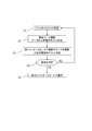
以下、図2に示す処理フローとともに、本実施形態に係る検査システムを説明する。
(撮像装置)
まず、センサ10を用いて所定の範囲におけるワーク(対象物)の有無を検知する(図2:S1)。センサ10は、例えば、生産ライン上で高速で移動するワークを検知するためのセンサであり、例えば赤外線センサを用いる。センサ10により、所定の範囲においてワークが検知されると、センサ10からトリガ生成回路20に対して信号が出力される。トリガ生成回路20は、センサ10からの信号に基づき撮像トリガ信号を生成する(図2:S2)。
まず、センサ10を用いて所定の範囲におけるワーク(対象物)の有無を検知する(図2:S1)。センサ10は、例えば、生産ライン上で高速で移動するワークを検知するためのセンサであり、例えば赤外線センサを用いる。センサ10により、所定の範囲においてワークが検知されると、センサ10からトリガ生成回路20に対して信号が出力される。トリガ生成回路20は、センサ10からの信号に基づき撮像トリガ信号を生成する(図2:S2)。
トリガ生成回路20は、例えばFPGA(Field programmable gate array)やASIC(Application Specific Integrated Circuit)などのロジック回路から構成されている。トリガ生成回路20は、センサ10から入力された信号に対してハードウエア処理をし、ハードウエア処理された撮像のためのトリガ信号が撮像装置30に伝達される。そして、撮像装置30がワークを撮像する(図2:S3)。
本実施形態によれば、トリガ生成回路20はロジック回路により構成されており、ハードウエア処理により並列処理がなされる。そして、トリガ生成回路20からの信号を、ソフトウエア処理を介することなく、撮像装置30に入力している。したがって、逐次処理を行うソフトウエア処理と比較して、無駄な遅延が生じにくい。トリガ生成回路20から、撮像装置30へのトリガ信号の伝達は有線で行うことが好ましい。
撮像装置30は、レンズ部と、撮像素子と、撮像素子から出力される信号を処理する信号処理部と、信号処理部により生成された画像データを出力する出力部と、トリガ信号が入力される入力部と、を有する。
入力部にトリガ信号が入力されると、撮像装置30は撮像を開始する。レンズ部は、撮像装置から取り外し可能に設けられており、対象物の大きさや、撮影シーンに応じて、適切なレンズ部を選択することができる。信号処理部は、撮像素子から出力される信号から画像データを生成する。出力部は、信号処理部で生成された画像データを出力する。
撮像素子は、光電変換部がアレイ状に配置された素子であって、例えば、CMOSセンサである。撮像素子は、各行で露光期間の開始と終了が異なるローリングシャッタ形式の撮像素子でもよいし、全行一括で露光期間の開始と終了が同時であるグローバル電子シャッター形式の撮像素子でもよい。
グローバル電子シャッター形式の本実施形態では、生産ラインで製造される製品(ワーク)の欠陥検査に用いることを想定している。そのため、ワークが高速で移動していることから、より精度の高い撮影を行うために、グローバル電子シャッター形式の撮像素子を用いることが好ましい。
(処理装置40)
撮像装置30から出力された画像データは、処理装置40に入力されて画像データの推定が行われる(図2:S4)。処理装置40では、画像データの対象物に関する推定が行われる。ここで、画像データの対象物に関する推定は、システムの用途に応じた処理を行う。以下では推定の処理として、撮像対象としてのワークが欠陥を有するかどうかを判定する外観検査処理を説明する。この他にも例えば、画像データに特定のものが存在するか否かを特定するシステムの場合は、特定する処理が推定の処理に相当する。また、自動振り分けシステムの場合は、ワークのサイズにより判別する処理が推定の処理に相当する。撮像装置30から処理装置40への画像データの伝送は、有線で行うことが好ましい。
撮像装置30から出力された画像データは、処理装置40に入力されて画像データの推定が行われる(図2:S4)。処理装置40では、画像データの対象物に関する推定が行われる。ここで、画像データの対象物に関する推定は、システムの用途に応じた処理を行う。以下では推定の処理として、撮像対象としてのワークが欠陥を有するかどうかを判定する外観検査処理を説明する。この他にも例えば、画像データに特定のものが存在するか否かを特定するシステムの場合は、特定する処理が推定の処理に相当する。また、自動振り分けシステムの場合は、ワークのサイズにより判別する処理が推定の処理に相当する。撮像装置30から処理装置40への画像データの伝送は、有線で行うことが好ましい。
処理装置40は、学習済モデルを有しており、学習済モデルを用いてワークに欠陥があるか否かを判断する。GPU(Graphics Processing Unit)42はデータをより多く並列処理することで効率的な演算を行うことができるので、ディープラーニングのような学習モデルを用いて複数回に渡り学習を行う場合にはGPU42で処理を行うことが有効である。そこで本実施形態では、処理装置40における処理にはCPU41に加えてGPU42を用いる。具体的には、学習モデルを含む学習プログラムを実行する場合に、CPU41とGPU42が協同して演算を行うことで学習を行う。なお、処理装置40の処理はCPU41またはGPU42のみにより演算が行われても良い。
CPU41とGPU42のそれぞれは、メモリを有しており、これらのメモリには、撮像装置から出力された画像データが保持される。上記のとおり、トリガ生成回路20により、撮像装置30には、同時刻にトリガ信号が入力されるため、CPU41とGPU42のメモリには、同時刻の画像データが保持されることになる。なお、処理装置40がCPU41のメモリ及びGPU42の主メモリとは異なるメモリを備えていてもよい。この場合は、画像データが主メモリに保持される。そして、必要に応じて、主メモリに保持された画像データがCPU41のメモリ及びGPU42のメモリに書き込まれる。
GPU42は、メモリに保持された画像データにアクセスし、並列的に画像データを処理する。GPU42は、学習済のモデルを用いて、ワークに欠陥があるか否かを判断する。GPU42は、CPU41よりも定型的な膨大な計算処理を行うのに適しており、GPU42は、ワークの画像データから欠陥の有無を判定する処理を速く行うことができる。
処理装置40は、撮像装置30により取得された画像データに基づき、画像データの領域に欠陥が有るか否かを判定する(図2:S5)。処理装置40により行われた判定結果は、PLC(Programmable Logic Controller)50に出力される、ワークに欠陥があるという最終判定結果の場合、PLC50は、ロボット60に動作制御用の信号を入力する。ロボット60は、ワークの移動動作を切り替え、欠陥があると判定されたワークを生産ラインから移動させる(図2:S6)。
処理装置40から、PLC50へ判定結果を出力する際には、高速の信号伝送は要求されていない。そのため、Ethernetなどの汎用規格の有線や無線などを使って、信号転送を行うことができる。
(学習済モデル430)
図3は、処理装置40のGPU42で行われるワークの欠陥判定を行うAIを説明するための図である。
図3は、処理装置40のGPU42で行われるワークの欠陥判定を行うAIを説明するための図である。
図3(A)は、学習フェーズの概念図である。学習モデル420は、欠陥判定のアルゴリズムを有し、学習モデル420に対して、教師データを入力する。教師データは、良品のワーク、第1の欠陥を含むワーク、第1の欠陥とは異なる第2の欠陥を含むワークなどをそれぞれ生産ラインに流して撮像した画像データである。つまり、教師データとして、L枚の良品画像411、M枚の第1の欠陥画像412、N枚の第2の欠陥画像413、などを入力する。AIにより、学習モデル420のアルゴリズムを、より精度の高いアルゴリズムとなるように学習させたものが学習済モデル430である。
機械学習の具体的なアルゴリズムとしては、最近傍法、ナイーブベイズ法、決定木、サポートベクターマシンなどを利用してもよい。またニューラルネットワークを利用して、学習するための特徴量、結合重みづけ係数を自ら生成する深層学習(ディープラーニング)であってもよい。たとえば、深層学習のモデルとして、CNNモデル(Convolutional Neural Network Model)を用いてもよい。
図3(B)は、推定フェーズの概念図である。学習フェーズにより構築した学習済モデル430に対して、ワーク画像440を入力すると、欠陥有無の判定結果450が出力される。この学習済モデル430を用いた処理はGPU42によって実行される。ワーク画像440とは、具体的には、生産ラインにワークを流して撮像装置30で撮像した画像データである。
次に、図4及び図5を参照しながら、学習済データの生成方法について説明する。
教師データの生成に使用されるワークは前述の通り、良品のワーク、第1の欠陥を含むワーク、第2の欠陥を含むワーク等を撮像した画像データである。
本実施形態では、第1の撮像条件と第2の撮像条件とでシャッタースピードを変えている。具体的には、あるシャッタースピードで前述のワークを撮影した画像データを教師データとして用いて学習済モデルを作成する工程を、学習済モデルにおける推定の精度が所定の精度以上となるまで、シャッタースピードを変えながら繰り返し行っている。例えば、図4(b)に示すように、シャッタースピードが遅すぎるとワークにおける欠陥がぼけるため欠陥の有無を判別することができない。したがって、これらの画像データを教師モデルとして学習モデルに入力しても、構築された学習済モデルで欠陥の有無を認識しにくい。一方で、シャッタースピードを速くしすぎると、図4(c)に示すように欠陥の判定を行うことはできるものの、照明の光量を多くする必要が出てきて汎用性が低下する。例えば、暗所における検査が必要な場合において利用することができない等の撮影場所での制限が課される。また、一定以上の光量が必要となるため、高価な照明が必要とされる可能性がある。本実施形態では、ある撮像条件でこれらのワークを撮像した画像データを教師データとして用いた学習済モデルを生成する。この学習済モデルの精度を判定して精度が所定の値よりも低い場合には撮像条件を変えて撮像した画像データを教師データとして用いて学習済モデルを生成する。そして精度が所定の値以上となるまで教師データを生成から精度の判定を繰り返し行い、精度が所定の値以上である学習済モデルを検査システムに使用する。これにより、画像データのワークに関する推定の処理の精度を高くすることができる。
以下で、学習済モデル430の生成方法について具体的に説明する。
まず、撮像装置のシャッタースピードを所定のシャッタースピード(第1のシャッタースピード)に設定する(図5:S1)。第1のシャッタースピードはできるだけ遅くすることが好ましい。前述の通り、シャッタースピードが速い場合は汎用性が低下する。第1のシャッタースピードで生成した教師データに基づく学習済モデルが精度を判定するステップS4において、所定の精度であると判定された場合に、過剰性能となる場合がある。第1のシャッタースピードを遅くしておくことで、過剰性能となることを防ぐことができる。例えば第1のシャッタースピードを8ms以上20ms以下に設定する。
次に、ワークが搭載された生産ラインを動かし、ワークと撮像装置の相対位置とを変化させながら複数のワークを撮影して画像データを作成し、画像データを教師データとして学習済モデルを作成する。このとき、複数のワークとして欠陥1を含むワークおよび良品のワークを少なくとも用いる。複数のワークとして、欠陥1とは異なる欠陥2を含むワーク等を用いることにより、良否判定の精度を向上させることができる。
教師データとして、ワークのXY座標を変えて撮像した画像データ、ワークを回転させて撮像した画像データをさらに用いてもよい。これらの画像データを教師データとして学習モデルに入力することにより、ワークが所定の位置からずれている場合にも精度を下げることなく良否判定を行うことができる。
次に、第1のシャッタースピードに設定した撮像装置で、複数のワークを撮影する。そして、得られた画像データから良否判定を行い、学習済モデルが所定の精度となっているかどうかを判定する(図5:S4)。
ステップS4において精度を判定した結果、所定の精度よりも低い場合は、ステップS1に戻り、シャッタースピードを調整する。なお、ステップS1に戻ってワークを撮影する場合に、第1のシャッタースピードで撮影したワークと同じワークを使ってもよいし、異なるワークを使ってもよい。ステップS4において精度を判定した結果、所定の精度以上の場合は学習済モデルとして、撮像装置のシャッタースピードを該当のシャッタースピードに設定し、構築された学習済モデルを用いて複数のワークの認識処理を行う。ステップS4において精度を判定した結果、所定の精度よりも低い場合は、シャッタースピードを第2のシャッタースピードに変更し、所定の精度以上となるまでステップS1からステップS4を繰り返し行う。
本実施形態では、教師データとして、一定の認識精度を保つことができるシャッタースピードで撮像された画像データを教師データとして入力して学習済モデルを構築している。したがって、ワークの認識処理の精度を高くすることができる。
なお、第1の撮像条件と第2の撮像条件は、シャッタースピードを変えたもののほかに公知の条件を変更したものであってもよい。
なお、図1では、処理装置40で学習済モデルの生成を行うが、生成された学習済モデルを処理装置40に入力してもよい。例えば、撮像装置で撮像した画像データを情報端末に伝達し、情報端末で学習済モデルの生成を行い、所定の精度以上の学習済モデルを処理装置40に入力してもよい。情報端末とは、例えば、パソコン等のコンピュータである。
本発明は上記実施の形態に制限されるものではなく、本発明の精神及び範囲から離脱することなく、様々な変更及び変形が可能である。従って、本発明の範囲を公にするために以下の請求項を添付する。
本願は、2019年5月30日提出の日本国特許出願特願2019-101750を基礎として優先権を主張するものであり、その記載内容の全てをここに援用する。
Claims (20)
- 撮像装置と、前記撮像装置により撮像した画像データが入力される学習モデルを有する処理装置と、を備えるシステムの制御方法であって、
第1の撮像条件に設定された前記撮像装置によって、前記撮像装置に対する相対位置を変化させながら第1のワークを撮像することで、第1の画像データを得る工程と、
前記第1の画像データを教師データとして用いて、前記学習モデルによる機械学習を行う工程と、
前記第1の撮像条件に設定された前記撮像装置によって、前記撮像装置に対する相対位置を変化させながら前記第1のワークとは別の第2のワークを撮像することで、第2の画像データを得る工程と、
前記第2の画像データを、学習済の前記学習モデルに入力し、前記第2の画像データから前記第2のワークに関する推定を行う工程と、
前記推定の精度が所定の値よりも低い場合に、前記第1の撮像条件とは異なる第2の撮像条件に設定された前記撮像装置によって、前記撮像装置に対する相対位置を変化させながら第3のワークを撮像することで、第3の画像データを得る工程、および、前記第3の画像データを教師データとして用いて、前記学習モデルによる機械学習を行う工程を行う、
ことを特徴とするシステムの制御方法。 - 前記撮像装置は、グローバル電子シャッター形式の撮像素子を含むことを特徴とする請求項1に記載の制御方法。
- 前記撮像条件は、シャッタースピードであることを特徴とする請求項1又は2に記載の制御方法。
- 前記第1の撮像条件におけるシャッタースピードは、前記第2の撮像条件におけるシャッタースピードよりも遅いことを特徴とする請求項3に記載の制御方法。
- 前記推定を行う工程において、前記学習モデルは、入力された前記画像データのワークが欠陥を有するか否かを出力することを特徴とする請求項1乃至4のいずれか1項に記載の制御方法。
- 前記教師データとして、良品のワークの画像データ、及び欠陥を含むワークの画像データを用いることを特徴とする請求項5に記載の制御方法。
- 前記欠陥を含むワークの画像データとして、第1の欠陥を含むワークの画像データと、第1の欠陥とは異なる第2の欠陥を含むワークの画像データと、を用いることを特徴とする請求項6に記載の制御方法。
- 前記第2の撮像条件に設定された前記撮像装置によって、前記学習モデルによる機械学習を行う工程の後に、
前記第2の撮像条件に設定された前記撮像装置によって、前記撮像装置に対する相対位置を変化させながら前記第3のワークとは別の第4のワークを撮像することで第4の画像データを得る工程と、
前記第4の画像データを、学習済の前記学習モデルに入力し、前記第4の画像データから前記第4のワークに関する推定を行う工程を備えることを特徴とする請求項1乃至7のいずれか1項に記載の制御方法。 - 前記処理装置は、GPUを備え、
前記GPUにより前記推定を行うことを特徴とする請求項1乃至8のいずれか1項に記載の制御方法。 - 前記GPUはメモリを備え、
前記メモリには前記撮像装置から出力された前記画像データが保持されることを特徴とする請求項9に記載の制御方法。 - 前記システムは、センサと、前記撮像装置に撮像トリガ信号を伝達するトリガ生成回路と、を備え、
前記第1の画像データを得る工程において、所定の範囲内における前記第1のワークを前記センサが検知すると、前記センサから前記トリガ生成回路に信号が出力され、
前記撮像装置は、前記信号に基づき出力された前記撮像トリガ信号に基づき前記第1のワークを撮像することを特徴とする請求項1乃至10のいずれか1項に記載の制御方法。 - 前記トリガ生成回路は、ロジック回路により構成され、ソフトウエア処理を介することなく前記撮像装置に前記トリガ信号を伝達することを特徴とする請求項11に記載の制御方法。
- 前記学習モデルは、最近傍法、ナイーブベイズ法、決定木、サポートベクターマシン、又はニューラルネットワークを用いることを特徴とする請求項1乃至12のいずれか1項に記載の制御方法。
- 撮像装置と、前記撮像装置により撮像した画像データが入力される学習モデルを有する処理装置と、を備えるシステムであって、
前記処理装置は、
第1の撮像条件に設定された前記撮像装置によって、前記撮像装置に対する相対位置を変化させながら第1のワークを撮像することで得られた第1の画像データを教師データとして用いて前記学習モデルによる機械学習を行い、
前記第1の撮像条件に設定された前記撮像装置によって、前記撮像装置に対する相対位置を変化させながら前記第1のワークとは別の第2のワークを撮像することで得られた第2の画像データを学習済の前記学習モデルに入力し、前記第2の画像データから前記第2のワークに関する推定を行い、
前記推定の精度が所定の値よりも低い場合に、前記第1の撮像条件とは異なる第2の撮像条件に設定された前記撮像装置によって、前記撮像装置に対する相対位置を変化させながら第3のワークを撮像することで得られた第3の画像データを教師データとして用いて、前記学習モデルによる機械学習を行う工程を行う、
ことを特徴とするシステム。 - 前記撮像条件は、シャッタースピードであることを特徴とする請求項14に記載のシステム。
- 前記システムは、センサと、前記撮像装置に撮像トリガ信号を伝達するトリガ生成回路と、を備え、
前記センサは、所定の範囲内に前記第1のワークがあることを検知すると前記トリガ生成回路に信号を出力し、
前記撮像装置は、前記信号に基づき出力される前記トリガ生成回路からの前記撮像トリガ信号に基づき前記第1のワークを撮像することを特徴とする請求項14又は15に記載のシステム。 - 前記学習済の学習モデルは、入力された前記画像データのワークが欠陥を有するか否かを出力することを特徴とする請求項16に記載のシステム。
- 前記システムは、ロボットを備え、
前記学習済の学習モデルによって欠陥を有すると判断されたワークを移動させることを特徴とする請求項17に記載のシステム。 - 前記システムは、前記学習済の学習モデルから、前記画像データのワークが欠陥を有する否かが伝達されるPLCを備え、
前記処理装置と前記PLCとは無線で接続され、
前記センサと前記トリガ生成回路とは有線で接続されることを特徴とする請求項17又は18に記載のシステム。 - 前記システムは、前記学習済の学習モデルから、前記画像データのワークが欠陥を有する否かが伝達されるPLCを備え、
前記処理装置から前記PLCへの信号の転送速度は、前記センサから前記トリガ生成回路への信号の転送速度よりも遅いことを特徴とする請求項17又は18に記載のシステム。
Priority Applications (1)
| Application Number | Priority Date | Filing Date | Title |
|---|---|---|---|
| US17/533,907 US20220084182A1 (en) | 2019-05-30 | 2021-11-23 | Control method for controlling system and system |
Applications Claiming Priority (2)
| Application Number | Priority Date | Filing Date | Title |
|---|---|---|---|
| JP2019101750A JP7267841B2 (ja) | 2019-05-30 | 2019-05-30 | システムの制御方法、及びシステム |
| JP2019-101750 | 2019-05-30 |
Related Child Applications (1)
| Application Number | Title | Priority Date | Filing Date |
|---|---|---|---|
| US17/533,907 Continuation US20220084182A1 (en) | 2019-05-30 | 2021-11-23 | Control method for controlling system and system |
Publications (1)
| Publication Number | Publication Date |
|---|---|
| WO2020241540A1 true WO2020241540A1 (ja) | 2020-12-03 |
Family
ID=73553494
Family Applications (1)
| Application Number | Title | Priority Date | Filing Date |
|---|---|---|---|
| PCT/JP2020/020449 Ceased WO2020241540A1 (ja) | 2019-05-30 | 2020-05-25 | システムの制御方法、及びシステム |
Country Status (3)
| Country | Link |
|---|---|
| US (1) | US20220084182A1 (ja) |
| JP (1) | JP7267841B2 (ja) |
| WO (1) | WO2020241540A1 (ja) |
Families Citing this family (6)
| Publication number | Priority date | Publication date | Assignee | Title |
|---|---|---|---|---|
| EP4038374A4 (en) * | 2019-09-30 | 2023-10-25 | Musashi AI North America Inc. | System and method for ai visual inspection |
| JP7509033B2 (ja) * | 2020-12-25 | 2024-07-02 | 新東工業株式会社 | 検査装置、検査方法、機械学習装置、及び機械学習方法 |
| CN113793333B (zh) * | 2021-11-15 | 2022-02-18 | 常州微亿智造科技有限公司 | 应用于工业质检的缺陷图片生成方法及装置 |
| WO2024024283A1 (ja) * | 2022-07-29 | 2024-02-01 | 株式会社Jvcケンウッド | 画像認識支援装置、方法及びプログラム |
| CN115400982B (zh) * | 2022-08-17 | 2025-08-26 | 烟台东泽电气科技股份有限公司 | 一种钢厂顶头检测系统 |
| JP2024145720A (ja) * | 2023-03-31 | 2024-10-15 | 株式会社キーエンス | スマートカメラ及び画像検査システム |
Citations (3)
| Publication number | Priority date | Publication date | Assignee | Title |
|---|---|---|---|---|
| JP2012252507A (ja) * | 2011-06-02 | 2012-12-20 | Panasonic Corp | 人物属性推定システム、人物属性推定装置、及び人物属性推定方法 |
| JP2018097731A (ja) * | 2016-12-15 | 2018-06-21 | 株式会社Fuji | 画像処理システム及び画像処理方法 |
| JP2018137275A (ja) * | 2017-02-20 | 2018-08-30 | 株式会社日立ハイテクノロジーズ | 試料観察装置および試料観察方法 |
Family Cites Families (17)
| Publication number | Priority date | Publication date | Assignee | Title |
|---|---|---|---|---|
| IL149588A (en) * | 2001-05-11 | 2007-07-24 | Orbotech Ltd | Image searching defect detector |
| US7545949B2 (en) * | 2004-06-09 | 2009-06-09 | Cognex Technology And Investment Corporation | Method for setting parameters of a vision detector using production line information |
| US9092841B2 (en) * | 2004-06-09 | 2015-07-28 | Cognex Technology And Investment Llc | Method and apparatus for visual detection and inspection of objects |
| US8891852B2 (en) * | 2004-06-09 | 2014-11-18 | Cognex Technology And Investment Corporation | Method and apparatus for configuring and testing a machine vision detector |
| JP4556993B2 (ja) * | 2007-12-07 | 2010-10-06 | セイコーエプソン株式会社 | 状態検査システム |
| EP2128793B1 (de) * | 2008-05-28 | 2012-10-17 | Pepperl + Fuchs GmbH | Verfahren und Vorrichtung zum Überprüfen von Druckerzeugnissen, Computerprogramm und Computerprogrammprodukt |
| IT1403978B1 (it) * | 2011-02-15 | 2013-11-08 | Datalogic Automation Srl | Metodo di acquisizione di immagini |
| US10043282B2 (en) * | 2015-04-13 | 2018-08-07 | Gerard Dirk Smits | Machine vision for ego-motion, segmenting, and classifying objects |
| JP6815764B2 (ja) * | 2016-06-28 | 2021-01-20 | 株式会社日立製作所 | 溶接監視システム |
| JP2019203691A (ja) * | 2016-11-11 | 2019-11-28 | オムロン株式会社 | 照明装置 |
| WO2018136262A1 (en) * | 2017-01-20 | 2018-07-26 | Aquifi, Inc. | Systems and methods for defect detection |
| JP7166767B2 (ja) * | 2017-05-25 | 2022-11-08 | キヤノン株式会社 | 機器、製造方法、およびシステム |
| JP6967373B2 (ja) * | 2017-05-31 | 2021-11-17 | 株式会社キーエンス | 画像検査装置 |
| US20200334801A1 (en) * | 2017-12-06 | 2020-10-22 | Nec Corporation | Learning device, inspection system, learning method, inspection method, and program |
| JP7090446B2 (ja) * | 2018-03-22 | 2022-06-24 | 株式会社キーエンス | 画像処理装置 |
| US11024023B2 (en) * | 2018-11-19 | 2021-06-01 | Vision Guided Robotics LLC | Inspection system |
| US11076088B2 (en) * | 2019-09-24 | 2021-07-27 | Sony Corporation | Artificial intelligence (AI)-based control of imaging parameters of image-capture apparatus |
-
2019
- 2019-05-30 JP JP2019101750A patent/JP7267841B2/ja active Active
-
2020
- 2020-05-25 WO PCT/JP2020/020449 patent/WO2020241540A1/ja not_active Ceased
-
2021
- 2021-11-23 US US17/533,907 patent/US20220084182A1/en active Pending
Patent Citations (3)
| Publication number | Priority date | Publication date | Assignee | Title |
|---|---|---|---|---|
| JP2012252507A (ja) * | 2011-06-02 | 2012-12-20 | Panasonic Corp | 人物属性推定システム、人物属性推定装置、及び人物属性推定方法 |
| JP2018097731A (ja) * | 2016-12-15 | 2018-06-21 | 株式会社Fuji | 画像処理システム及び画像処理方法 |
| JP2018137275A (ja) * | 2017-02-20 | 2018-08-30 | 株式会社日立ハイテクノロジーズ | 試料観察装置および試料観察方法 |
Also Published As
| Publication number | Publication date |
|---|---|
| JP7267841B2 (ja) | 2023-05-02 |
| JP2020198471A (ja) | 2020-12-10 |
| US20220084182A1 (en) | 2022-03-17 |
Similar Documents
| Publication | Publication Date | Title |
|---|---|---|
| WO2020241540A1 (ja) | システムの制御方法、及びシステム | |
| JP7476145B2 (ja) | 画像処理方法および撮影装置 | |
| JP6973623B2 (ja) | 学習済みモデルの生成方法、学習済みモデル、表面欠陥検出方法、鋼材の製造方法、合否判定方法、等級判定方法、表面欠陥判定プログラム、合否判定プログラム、判定システム、及び鋼材の製造設備 | |
| US11245842B2 (en) | Appearance inspection system, setting device, image processing device, inspection method, and program | |
| CN109483573A (zh) | 机器学习装置、机器人系统以及机器学习方法 | |
| JP6955211B2 (ja) | 識別装置、識別方法及びプログラム | |
| JP7374611B2 (ja) | 撮像システム | |
| CN113012228B (zh) | 一种工件定位系统及基于深度学习的工件定位方法 | |
| US20150042784A1 (en) | Image photographing method and image photographing device | |
| JP2018120373A (ja) | 産業機器用の画像認識装置及び画像認識方法 | |
| US12444034B2 (en) | Teacher data generation method, trained learning model, and system | |
| JP2021026599A (ja) | 画像処理システム | |
| CN119722588A (zh) | 一种基于机器学习的线路板缺陷检测系统 | |
| WO2020213194A1 (ja) | 表示制御システム、および、表示制御方法 | |
| JP2011174896A (ja) | 撮像装置及び撮像方法 | |
| CN110111332A (zh) | 基于深度卷积神经网络的胶原蛋白肠衣缺陷检测模型、检测方法及系统 | |
| CN119841105A (zh) | 码垛机控制系统 | |
| US12459130B2 (en) | Robot operation system, robot operation method, and program | |
| US20250317661A1 (en) | A data processing system for processing pixel data to be indicative of contrast | |
| CN115219492B (zh) | 一种三维物体的外观图像采集方法及装置 | |
| CN116724224A (zh) | 加工面判定装置、加工面判定程序、加工面判定方法、加工系统、推论装置及机器学习装置 | |
| JP2019105588A (ja) | 情報処理装置、システム、情報処理方法及びプログラム | |
| JP7827844B2 (ja) | 対象領域抽出装置、方法、及びシステム | |
| CN119273976B (zh) | 基于视觉神经网络的智能搬运机器人避障方法及系统 | |
| CN116197911B (zh) | 一种机械臂随机抓取方法 |
Legal Events
| Date | Code | Title | Description |
|---|---|---|---|
| 121 | Ep: the epo has been informed by wipo that ep was designated in this application |
Ref document number: 20813400 Country of ref document: EP Kind code of ref document: A1 |
|
| NENP | Non-entry into the national phase |
Ref country code: DE |
|
| 122 | Ep: pct application non-entry in european phase |
Ref document number: 20813400 Country of ref document: EP Kind code of ref document: A1 |