WO2020241259A1 - Information presentation device, information presentation method, and information presentation program - Google Patents
Information presentation device, information presentation method, and information presentation program Download PDFInfo
- Publication number
- WO2020241259A1 WO2020241259A1 PCT/JP2020/019127 JP2020019127W WO2020241259A1 WO 2020241259 A1 WO2020241259 A1 WO 2020241259A1 JP 2020019127 W JP2020019127 W JP 2020019127W WO 2020241259 A1 WO2020241259 A1 WO 2020241259A1
- Authority
- WO
- WIPO (PCT)
- Prior art keywords
- driver
- vehicle
- information
- risk
- outside
- Prior art date
Links
- 238000000034 method Methods 0.000 title claims description 57
- 238000001514 detection method Methods 0.000 claims abstract description 45
- 230000008859 change Effects 0.000 claims description 18
- 230000009467 reduction Effects 0.000 claims description 8
- 230000007423 decrease Effects 0.000 claims description 7
- 230000008569 process Effects 0.000 description 40
- 238000013459 approach Methods 0.000 description 24
- 230000006399 behavior Effects 0.000 description 14
- 230000006870 function Effects 0.000 description 14
- 230000004397 blinking Effects 0.000 description 9
- 101100341529 Oryza sativa subsp. japonica ITPK2 gene Proteins 0.000 description 8
- 101100274420 Arabidopsis thaliana CID6 gene Proteins 0.000 description 5
- 230000004048 modification Effects 0.000 description 5
- 238000012986 modification Methods 0.000 description 5
- 238000004590 computer program Methods 0.000 description 2
- 230000000694 effects Effects 0.000 description 2
- 230000009471 action Effects 0.000 description 1
- 238000004364 calculation method Methods 0.000 description 1
- 230000003247 decreasing effect Effects 0.000 description 1
- 238000010586 diagram Methods 0.000 description 1
- 238000010191 image analysis Methods 0.000 description 1
- 239000004065 semiconductor Substances 0.000 description 1
Images


Classifications
-
- B—PERFORMING OPERATIONS; TRANSPORTING
- B60—VEHICLES IN GENERAL
- B60Q—ARRANGEMENT OF SIGNALLING OR LIGHTING DEVICES, THE MOUNTING OR SUPPORTING THEREOF OR CIRCUITS THEREFOR, FOR VEHICLES IN GENERAL
- B60Q9/00—Arrangement or adaptation of signal devices not provided for in one of main groups B60Q1/00 - B60Q7/00, e.g. haptic signalling
- B60Q9/008—Arrangement or adaptation of signal devices not provided for in one of main groups B60Q1/00 - B60Q7/00, e.g. haptic signalling for anti-collision purposes
-
- G—PHYSICS
- G08—SIGNALLING
- G08G—TRAFFIC CONTROL SYSTEMS
- G08G1/00—Traffic control systems for road vehicles
- G08G1/16—Anti-collision systems
- G08G1/165—Anti-collision systems for passive traffic, e.g. including static obstacles, trees
-
- B—PERFORMING OPERATIONS; TRANSPORTING
- B60—VEHICLES IN GENERAL
- B60K—ARRANGEMENT OR MOUNTING OF PROPULSION UNITS OR OF TRANSMISSIONS IN VEHICLES; ARRANGEMENT OR MOUNTING OF PLURAL DIVERSE PRIME-MOVERS IN VEHICLES; AUXILIARY DRIVES FOR VEHICLES; INSTRUMENTATION OR DASHBOARDS FOR VEHICLES; ARRANGEMENTS IN CONNECTION WITH COOLING, AIR INTAKE, GAS EXHAUST OR FUEL SUPPLY OF PROPULSION UNITS IN VEHICLES
- B60K35/00—Instruments specially adapted for vehicles; Arrangement of instruments in or on vehicles
-
- B—PERFORMING OPERATIONS; TRANSPORTING
- B60—VEHICLES IN GENERAL
- B60W—CONJOINT CONTROL OF VEHICLE SUB-UNITS OF DIFFERENT TYPE OR DIFFERENT FUNCTION; CONTROL SYSTEMS SPECIALLY ADAPTED FOR HYBRID VEHICLES; ROAD VEHICLE DRIVE CONTROL SYSTEMS FOR PURPOSES NOT RELATED TO THE CONTROL OF A PARTICULAR SUB-UNIT
- B60W50/00—Details of control systems for road vehicle drive control not related to the control of a particular sub-unit, e.g. process diagnostic or vehicle driver interfaces
- B60W50/08—Interaction between the driver and the control system
- B60W50/14—Means for informing the driver, warning the driver or prompting a driver intervention
-
- G—PHYSICS
- G02—OPTICS
- G02B—OPTICAL ELEMENTS, SYSTEMS OR APPARATUS
- G02B27/00—Optical systems or apparatus not provided for by any of the groups G02B1/00 - G02B26/00, G02B30/00
- G02B27/0093—Optical systems or apparatus not provided for by any of the groups G02B1/00 - G02B26/00, G02B30/00 with means for monitoring data relating to the user, e.g. head-tracking, eye-tracking
-
- G—PHYSICS
- G06—COMPUTING; CALCULATING OR COUNTING
- G06V—IMAGE OR VIDEO RECOGNITION OR UNDERSTANDING
- G06V20/00—Scenes; Scene-specific elements
- G06V20/50—Context or environment of the image
- G06V20/56—Context or environment of the image exterior to a vehicle by using sensors mounted on the vehicle
- G06V20/58—Recognition of moving objects or obstacles, e.g. vehicles or pedestrians; Recognition of traffic objects, e.g. traffic signs, traffic lights or roads
-
- G—PHYSICS
- G06—COMPUTING; CALCULATING OR COUNTING
- G06V—IMAGE OR VIDEO RECOGNITION OR UNDERSTANDING
- G06V20/00—Scenes; Scene-specific elements
- G06V20/50—Context or environment of the image
- G06V20/59—Context or environment of the image inside of a vehicle, e.g. relating to seat occupancy, driver state or inner lighting conditions
- G06V20/597—Recognising the driver's state or behaviour, e.g. attention or drowsiness
-
- G—PHYSICS
- G06—COMPUTING; CALCULATING OR COUNTING
- G06V—IMAGE OR VIDEO RECOGNITION OR UNDERSTANDING
- G06V40/00—Recognition of biometric, human-related or animal-related patterns in image or video data
- G06V40/10—Human or animal bodies, e.g. vehicle occupants or pedestrians; Body parts, e.g. hands
- G06V40/18—Eye characteristics, e.g. of the iris
-
- G—PHYSICS
- G08—SIGNALLING
- G08G—TRAFFIC CONTROL SYSTEMS
- G08G1/00—Traffic control systems for road vehicles
- G08G1/16—Anti-collision systems
-
- G—PHYSICS
- G08—SIGNALLING
- G08G—TRAFFIC CONTROL SYSTEMS
- G08G1/00—Traffic control systems for road vehicles
- G08G1/16—Anti-collision systems
- G08G1/166—Anti-collision systems for active traffic, e.g. moving vehicles, pedestrians, bikes
-
- B—PERFORMING OPERATIONS; TRANSPORTING
- B60—VEHICLES IN GENERAL
- B60W—CONJOINT CONTROL OF VEHICLE SUB-UNITS OF DIFFERENT TYPE OR DIFFERENT FUNCTION; CONTROL SYSTEMS SPECIALLY ADAPTED FOR HYBRID VEHICLES; ROAD VEHICLE DRIVE CONTROL SYSTEMS FOR PURPOSES NOT RELATED TO THE CONTROL OF A PARTICULAR SUB-UNIT
- B60W50/00—Details of control systems for road vehicle drive control not related to the control of a particular sub-unit, e.g. process diagnostic or vehicle driver interfaces
- B60W50/08—Interaction between the driver and the control system
- B60W50/14—Means for informing the driver, warning the driver or prompting a driver intervention
- B60W2050/146—Display means
-
- B—PERFORMING OPERATIONS; TRANSPORTING
- B60—VEHICLES IN GENERAL
- B60W—CONJOINT CONTROL OF VEHICLE SUB-UNITS OF DIFFERENT TYPE OR DIFFERENT FUNCTION; CONTROL SYSTEMS SPECIALLY ADAPTED FOR HYBRID VEHICLES; ROAD VEHICLE DRIVE CONTROL SYSTEMS FOR PURPOSES NOT RELATED TO THE CONTROL OF A PARTICULAR SUB-UNIT
- B60W2540/00—Input parameters relating to occupants
- B60W2540/225—Direction of gaze
-
- G—PHYSICS
- G01—MEASURING; TESTING
- G01S—RADIO DIRECTION-FINDING; RADIO NAVIGATION; DETERMINING DISTANCE OR VELOCITY BY USE OF RADIO WAVES; LOCATING OR PRESENCE-DETECTING BY USE OF THE REFLECTION OR RERADIATION OF RADIO WAVES; ANALOGOUS ARRANGEMENTS USING OTHER WAVES
- G01S13/00—Systems using the reflection or reradiation of radio waves, e.g. radar systems; Analogous systems using reflection or reradiation of waves whose nature or wavelength is irrelevant or unspecified
- G01S13/88—Radar or analogous systems specially adapted for specific applications
- G01S13/93—Radar or analogous systems specially adapted for specific applications for anti-collision purposes
- G01S13/931—Radar or analogous systems specially adapted for specific applications for anti-collision purposes of land vehicles
-
- G—PHYSICS
- G02—OPTICS
- G02B—OPTICAL ELEMENTS, SYSTEMS OR APPARATUS
- G02B27/00—Optical systems or apparatus not provided for by any of the groups G02B1/00 - G02B26/00, G02B30/00
- G02B27/01—Head-up displays
- G02B27/0101—Head-up displays characterised by optical features
- G02B2027/0141—Head-up displays characterised by optical features characterised by the informative content of the display
-
- G—PHYSICS
- G02—OPTICS
- G02B—OPTICAL ELEMENTS, SYSTEMS OR APPARATUS
- G02B27/00—Optical systems or apparatus not provided for by any of the groups G02B1/00 - G02B26/00, G02B30/00
- G02B27/01—Head-up displays
- G02B27/0149—Head-up displays characterised by mechanical features
- G02B2027/0167—Emergency system, e.g. to prevent injuries
Definitions
- This disclosure relates to an information presentation device, an information presentation method, and an information presentation program that presents information to the driver of a vehicle.
- Patent Document 1 is configured to detect the movement of the driver's line of sight and an obstacle, display a warning at a position outside the driver's line of sight, and then guide the movement of the line of sight to the obstacle. Guidance devices are described.
- the information presenting device that presents the outside risk information regarding the outside risk to the driver presents the outside risk information to the driver even though the driver is aware of the risk. Then, the driver feels that the presentation of the information is troublesome, and the problem is found that the driver does not use the function of presenting the risk information outside the vehicle.
- One aspect of the present disclosure is an information presentation device mounted on a vehicle, which includes an external risk detection unit, a line-of-sight detection unit, a recognition determination unit, and an information presentation unit.
- the out-of-vehicle risk detection unit is configured to detect an out-of-vehicle risk object that exists in the vicinity of the vehicle and may be dangerous to the vehicle.
- the line-of-sight detection unit is configured to detect the line-of-sight direction of the driver of the vehicle.
- the recognition judgment unit is configured to determine whether or not the driver recognizes the outside risk object based on the detection result by the outside risk detection unit and the detection result by the line-of-sight detection unit.
- the information presentation unit is configured to present the outside risk information regarding the outside risk object to the driver. Then, the information presentation unit presents the outside risk information to the driver based on the judgment result by the recognition judgment unit, when the driver recognizes the outside risk object and when the driver recognizes the outside risk object. It changes depending on whether the object is not recognized.
- the information presenting device of the present disclosure configured in this way changes the presentation mode of the out-of-vehicle risk information according to whether or not the driver is aware of the out-of-vehicle risk object.
- the information presenting device of the present disclosure emphasizes and presents the out-of-vehicle risk information when the driver does not recognize the out-of-vehicle risk object, and when the driver recognizes the out-of-vehicle risk object. Can be presented without emphasizing out-of-vehicle risk information. That is, when the driver does not recognize the outside risk object, the information presenting device of the present disclosure presents the outside risk information so that the driver can recognize the outside risk object, and the driver presents the outside risk information. When the object is recognized, the risk information outside the vehicle can be presented so that the driver does not feel annoyed.
- the information presenting device of the present disclosure suppresses the occurrence of a situation in which the driver feels annoyed without impairing the function of enabling the driver to recognize the risk object outside the vehicle, and the risk information outside the vehicle. Can be presented.
- Another aspect of the present disclosure is an information presentation method for presenting information to the driver of a vehicle, which includes a recognition determination step and an information presentation step.
- the recognition judgment step determines whether or not the driver recognizes the risk object outside the vehicle based on the detection result by the risk detection unit outside the vehicle and the detection result by the line-of-sight detection unit.
- the information presentation step presents the outside risk information regarding the outside risk object to the driver. Then, in the information presentation step, based on the judgment result of the recognition judgment step, the presentation mode of presenting the outside risk information to the driver is determined when the driver recognizes the outside risk object and when the driver recognizes the outside risk object. It changes depending on whether the object is not recognized.
- the information presentation method of the present disclosure is a method executed by the information presentation device of the present disclosure, and by executing the method, the same effect as that of the information presentation device of the present disclosure can be obtained.
- Yet another aspect of the present disclosure is an information presentation program for causing the computer to function as a recognition judgment unit and an information presentation unit in order to present information to the driver of the vehicle.
- the computer controlled by the information presentation program of the present disclosure can form a part of the information presentation device of the present disclosure, and can obtain the same effect as the information presentation device of the present disclosure.
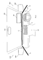
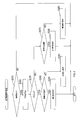
- the information presenting device 1 of the present embodiment is mounted on a vehicle, and as shown in FIG. 1, the radar device 2, the DSM3, the blinker sensor 4, the HUD5, the CID6, the MID7, the LED indicators 8, 9, 10, and the line LEDs 11, 12 , 13, speaker 14, vibrator 15, and control device 16.
- the vehicle equipped with the information presentation device 1 is referred to as a own vehicle.
- DSM is an abbreviation for Driver Status Monitor.
- HUD is an abbreviation for Head-Up Display.
- CID is an abbreviation for Center Information Display.
- MID is an abbreviation for Multi Information Display.
- LED is an abbreviation for Light Emitting Diode.
- the radar device 2 transmits the radar wave toward the periphery of the vehicle and receives the reflected radar wave, so that the distance R to the target that reflects the radar wave, the speed V of the target, and the target Detects the direction ⁇ .
- the radar device 2 calculates estimated values of the horizontal position x, the vertical position y, the horizontal speed Vx, and the vertical speed Vy from these detected values (R, V, ⁇ ), and these estimated values (x, y, Vx, Vy) is output to the control device 16 as a detection result.
- DSM3 captures the driver's face with a camera and detects the driver's line-of-sight direction by image analysis.
- the turn signal sensor 4 detects on and off of the right turn signal of the vehicle and on and off of the left turn signal.
- the HUD 5 irradiates display light for displaying an image from below the windshield WS of the vehicle toward the HUD display area HR of the windshield WS.
- a virtual image is projected on the windshield WS, and the driver can visually recognize the virtual image by superimposing it on the actual landscape in front of the vehicle in the HUD display area HR.
- CID6 is installed above the center cluster CC and displays various images on the display screen.
- the MID 7 is provided on the instrument panel IP in front of the driver's seat and displays various states of the vehicle on the display screen.
- the LED indicator 8 is installed on the mirror surface of the right side mirror SM1.
- the LED indicator 8 emits light to display an image showing the approach of the vehicle from the right rear of the own vehicle (hereinafter, right rear approach image).
- the LED indicator 9 is installed on the mirror surface of the left side mirror SM2.
- the LED indicator 9 emits light to display an image showing the approach of the vehicle from the left rear of the own vehicle (hereinafter, left rear approach image).
- the LED indicator 10 is installed on the mirror surface of the rear-view mirror BM.
- the line LEDs 11, 12, and 13 are formed by arranging a plurality of LED elements linearly, and are configured so that each of the plurality of LED elements can be turned on and off independently.
- the line LED 11 is arranged along the lower side of the windshield WS in the vicinity of the lower side of the rectangular windshield WS.
- the line LED 12 is arranged near the lower side of the rectangular driver's seat side window WD1 along the lower side of the driver's seat side window WD1.
- the line LED 13 is arranged near the lower side of the square passenger seat side window WD2 along the lower side of the passenger seat side window WD2.
- the speaker 14 is installed in the vehicle interior, and converts the voice electric signal input from the control device 16 into voice and outputs it.
- the vibrator 15 is installed in the vehicle interior.
- the vibrator 15 includes a vibration motor, and generates vibration by driving the vibration motor.
- the control device 16 is an electronic control device mainly composed of a microcomputer provided with a CPU 21, a ROM 22, a RAM 23, and the like.
- Various functions of the microcomputer are realized by the CPU 21 executing a program stored in a non-transitional substantive recording medium.
- ROM 22 corresponds to a non-transitional substantive recording medium in which a program is stored.
- the method corresponding to the program is executed.
- a part or all of the functions executed by the CPU 21 may be configured in hardware by one or a plurality of ICs or the like. Further, the number of microcomputers constituting the control device 16 may be one or a plurality.
- the control device 16 executes various processes based on the inputs from the radar device 2, the DSM3, and the blinker sensor 4, and performs various processes, such as the HUD5, CID6, MID7, LED indicators 8, 9, 10, line LEDs 11, 12, 13, and the speaker 14. Controls the vibrator 15.
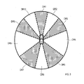
- the direction of the objects existing around the own vehicle is defined as follows. As shown in FIG. 3, the direction centered on the own vehicle is any of the direction ranges DR1, DR2, DR3, DR4, DR5, DR6, DR7, DR8, DR9, and DR10 in the clockwise direction from the traveling direction of the own vehicle. It is classified as.
- the directional range DR1 is also referred to as a front front.
- the directional range DR2 is also referred to as the front right.
- the directional range DR3 is also referred to as the front right side.
- the direction range DR4 is also referred to as the right side.
- the directional range DR5 is also referred to as the right rear side.
- the directional range DR6 is also referred to as front and rear.
- the directional range DR7 is also referred to as the left rear side.
- the directional range DR8 is also referred to as the left side.
- the directional range DR9 is also referred to as the left front side.
- the directional range DR10 is also referred to as the front left.
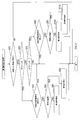
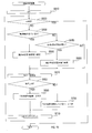
- the first information presentation process is a process that is repeatedly executed during the operation of the control device 16.
- the CPU 21 When the first information presentation process is executed, as shown in FIG. 4, the CPU 21 first in S10, based on the detection result of the radar device 2, the rear side of the own vehicle (that is, the direction range DR5 or the direction). It is determined whether or not a vehicle exists in the range DR7). Here, if the vehicle does not exist on the rear side of the own vehicle, the CPU 21 ends the first information presentation process. On the other hand, when the vehicle is on the rear side of the own vehicle, the CPU 21 determines in S20 whether or not the right blinker is blinking based on the detection result of the blinker sensor 4.
- the CPU 21 determines in S30 whether or not the HUD 5 is displaying the right rear approach image.
- the CPU 21 ends the first information presentation process.
- the CPU 21 recognizes the vehicle on the rear side of the own vehicle in S40 based on the determination result of the recognition determination process described later. Judge whether or not it is.
- the CPU 21 executes the first presentation instruction in S50 and ends the first information presentation process.
- the CPU 21 outputs an instruction to display a right rear approach image to the HUD 5, outputs a voice electric signal indicating a warning sound to the speaker 14, and outputs an instruction to vibrate to the vibrator 15. Then, an instruction to blink is output to the LED indicator 8.
- the HUD 5 displays the right rear approach image
- the speaker 14 outputs a warning sound
- the vibrator 15 vibrates
- the LED indicator 8 blinks the right rear approach image.
- the CPU 21 executes the second presentation instruction in S60 to end the first information presentation process.
- the CPU 21 outputs an instruction to turn on the LED indicator 8.
- the LED indicator 8 lights and displays the right rear approach image.
- the CPU 21 determines in S70 whether or not the left blinker is blinking based on the detection result of the blinker sensor 4.
- the CPU 21 determines in S80 whether or not the HUD 5 is displaying the left rear approach image.
- the CPU 21 ends the first information presentation process.
- the CPU 21 recognizing the vehicle on the rear side of the own vehicle based on the determination result of the recognition determination process in S90? Judge whether or not.
- the CPU 21 executes the third presentation instruction in S100 to end the first information presentation process.
- the CPU 21 outputs an instruction to display a left rear approach image to the HUD 5, outputs a voice electric signal indicating a warning sound to the speaker 14, and outputs an instruction to vibrate to the vibrator 15. Then, an instruction to blink is output to the LED indicator 9.
- the HUD 5 displays the left rear approach image
- the speaker 14 outputs a warning sound
- the vibrator 15 vibrates
- the LED indicator 9 blinks the left rear approach image.
- the CPU 21 executes the fourth presentation instruction in S110 to end the first information presentation process.
- the fourth presentation instruction specifically, the CPU 21 outputs an instruction to turn on the LED indicator 9.
- the LED indicator 9 lights and displays the left rear approach image.
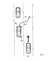
- the CPU 21 has a vehicle RC on the right rear side of the own vehicle MC, and the own vehicle MC changes lanes to the right.
- the right turn signal of the vehicle MC is blinking, it is determined whether or not to execute various instructions.
- the blinker lights WL1 and WL2 indicate that the right blinker of the own vehicle MC is blinking, and the arrow AL1 indicates that the own vehicle MC changes lanes to the right.
- the second information presentation process is a process that is repeatedly executed during the operation of the control device 16.
- the CPU 21 When the second information presentation process is executed, as shown in FIG. 6, the CPU 21 first determines in S210 whether or not a target exists around the own vehicle based on the detection result of the radar device 2. to decide. Here, if there is no target around the own vehicle, the CPU 21 ends the second information presentation process. On the other hand, when there is a target around the own vehicle, the CPU 21 determines the target in S210 based on the detection result of the radar device 2 in S220 (hereinafter, the target target). ) And the collision prediction time TTC with the own vehicle are calculated. TTC is an abbreviation for Time To Collision.
- the CPU 21 determines whether or not the collision prediction time TTC calculated in S220 is equal to or less than the preset risk determination value J1. That is, in S230, the CPU 21 determines that the risk level is high when the collision prediction time TTC is equal to or less than the risk level determination value J1. On the other hand, when the collision prediction time TTC exceeds the risk determination value J1, the CPU 21 determines that the risk is low.
- the CPU 21 recognizes the target target in S240 based on the determination result of the recognition determination process described later. Judge whether or not.
- the CPU 21 executes the fifth presentation instruction in S250 to end the second information presentation process.
- the CPU 21 outputs the presentation instruction to the display device arranged near the direction in which the target target exists (hereinafter, the risk direction). For example, if the target target exists on the right side of the own vehicle (that is, the direction range DR4) and the driver recognizes the target target, the CPU 21 is installed on the right side of the driver.
- the line LED 12 is blinked.
- the CPU 21 executes the sixth presentation instruction in S260 to end the second information presentation process.
- the CPU 21 outputs the following four instructions.
- the CPU 21 outputs a voice electric signal indicating a warning sound to the speaker 14.
- the CPU 21 outputs an instruction to vibrate at a high frequency to the vibrator 15.
- the CPU 21 outputs an instruction for displaying information indicating the risk direction to a display device arranged near the driver's gaze direction.
- the CPU 21 outputs an instruction to display a warning (for example, blinking an LED or an icon) to a display device located near the risk direction.
- the CPU 21 recognizes the target target in S270 based on the determination result of the recognition determination process. Judge whether or not it is.
- the CPU 21 executes the seventh presentation instruction in S280 to end the second information presentation process.
- the CPU 21 outputs the presentation instruction to the display device arranged near the risk direction. For example, if the target target exists on the right side of the own vehicle (that is, the direction range DR4) and the driver recognizes the target target, the CPU 21 is arranged on the right side of the driver. The line LED 12 is turned on.
- the CPU 21 executes the eighth presentation instruction in S290 to end the second information presentation process.
- the CPU 21 outputs the following four instructions.
- the CPU 21 outputs a voice electric signal indicating a warning sound to the speaker 14.
- the CPU 21 outputs an instruction to vibrate at a low frequency to the vibrator 15.
- the CPU 21 outputs an instruction for displaying information indicating the risk direction to a display device arranged near the driver's gaze direction.
- the CPU 21 outputs an instruction to display a warning (for example, lighting an LED or an icon) to a display device located near the risk direction.
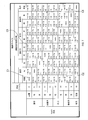
- the presentation in the 6th and 8th presentation instructions is performed by the combination of the reference device and the auxiliary device.
- the numbers shown in each column of FIG. 7 are the codes of the components of the information presentation device 1. For example, "5" indicates HUD5. "11" indicates that it is a line LED 11.
- the reference device is selected based on the risk direction.
- Auxiliary devices are selected based on the driver's gaze direction.
- the reference device when the risk direction is front and front is HUD5.
- the reference device when the risk directions are front right, front left, front right side and front left side is the line LED 11.
- the reference device when the risk direction is to the right is the line LED 12.
- the reference device when the risk direction is to the left is the line LED 13.
- the reference device when the risk direction is right rear side is the LED indicator 8.
- the reference device when the risk direction is left rear side is the LED indicator 9.
- the reference device when the risk direction is front-back is the LED indicator 10.
- the auxiliary devices when the driver's gaze direction is the front front are the speaker 14, the vibrator 15, and the HUD 5. However, if the risk direction is front and front, the auxiliary device is not used.
- Auxiliary devices when the driver's gaze direction is forward right are the speaker 14, the vibrator 15, and the line LED 11. However, if the risk direction is to the right front, the auxiliary device is not used.
- Auxiliary devices when the driver's gaze direction is left front are the speaker 14, the vibrator 15, and the line LED 11. However, if the risk direction is to the left front, the auxiliary device is not used.
- the auxiliary devices when the driver's gaze direction is the right front side are the speaker 14, the vibrator 15, and the line LED 11. However, if the risk direction is to the right front side, the auxiliary device is not used.
- the auxiliary devices when the driver's gaze direction is the left front side are the speaker 14, the vibrator 15, and the line LED 11. However, if the risk direction is the left front side, the auxiliary device is not used.
- Auxiliary devices when the driver's gaze direction is to the right are the speaker 14, the vibrator 15, and the line LED 12. However, if the risk direction is to the right, the auxiliary device will not be used.
- Auxiliary devices when the driver's gaze direction is to the left are the speaker 14, the vibrator 15, and the line LED 13. However, if the risk direction is to the left, the auxiliary device will not be used.
- Auxiliary devices when the driver's gaze direction is to the right rear side are the speaker 14, the vibrator 15, and the line LED 12. However, if the risk direction is to the right rear side, the auxiliary device is not used.
- the auxiliary devices when the driver's gaze direction is the left rear side are the speaker 14, the vibrator 15, and the line LED 13. However, if the risk direction is left rear side, the auxiliary device is not used.
- Auxiliary devices when the driver's gaze direction is front and rear are the speaker 14, the vibrator 15, and the HUD 5. However, if the risk direction is front and rear, the auxiliary device is not used. Further, when the risk direction is front front, HUD5 is not used as an auxiliary device. In this case, the warning sound from the speaker 14 and the vibration from the vibrator 15 first turn the driver forward and guide the driver in the risk direction with the HUD 5.
- column C1 indicates an auxiliary device when the risk direction is the front front and the driver's gaze direction is the front front. Since the column C1 describes "none", the auxiliary device is not used. That is, the reference device HUD5 is used. In this case, for example, as shown in FIG. 8, "forward attention" is displayed in the HUD display area HR.
- column C2 indicates an auxiliary device when the risk direction is the right rear side and the driver's gaze direction is the front front. Since "+ 14/15 + 5" is described in column C2, the speaker 14, the vibrator 15, and the HUD 5 are used as auxiliary devices. Then, the LED indicator 8 is used as a reference device. In this case, for example, as shown in FIG. 9, a right rear approach image is displayed in the HUD display area HR, a right rear approach image is displayed on the mirror surface of the right side mirror SM1, and a warning sound is output from the speaker 14. To. In addition, the vibrator 15 vibrates.
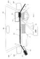
- Column C3 indicates an auxiliary device when the risk direction is the front front and the driver's gaze direction is the left front side. Since “+14 / 15 + 11” is described in column C3, the speaker 14, the vibrator 15, and the line LED 11 are used as auxiliary devices. Then, HUD5 is used as a reference device. In this case, for example, as shown in FIG. 10, "forward attention" is displayed in the HUD display area HR, and a warning sound is output from the speaker 14. In addition, the vibrator 15 vibrates. Further, the line LED 11 emits light so that the light LL1 moves from the left end of the line LED 11 to the region directly below the HUD display region HR, as shown by the arrow AL2.
- column C4 indicates an auxiliary device when the risk direction is the right front side and the driver's gaze direction is the left rear side. Since "+ 14/15 + 13" is described in column C4, the speaker 14, the vibrator 15, and the line LED 13 are used as auxiliary devices. Then, the line LED 11 is used as a reference device. In this case, for example, as shown in FIG. 11, a warning sound is output from the speaker 14. In addition, the vibrator 15 vibrates. Further, the line LED 13 emits light so that the light LL2 moves from the rear end to the front end of the line LED 13, as indicated by the arrow AL3.
- the line LED 11 emits light so that the light LL3 moves from the left end to the right end of the line LED 11 as indicated by the arrow AL4.
- the target is located at a position different from the end of the line LED 11 as seen from the driver, the light of the line LED 11 does not necessarily have to move to the end (that is, in the vicinity of the target). You may stop the position of the light).
- the line of sight may be guided to the HUD display area HR instead of the position of the target.
- the recognition determination process is a process that is repeatedly executed during the operation of the control device 16.
- the CPU 21 When the recognition determination process is executed, the CPU 21 first sets the target indication value n provided in the RAM 23 to 1 in S410, as shown in FIG. Next, in S420, the CPU 21 determines in S420 whether or not the target indicator value n is greater than the characteristic characteristic NUM, which indicates the total number of the targets currently detected by the radar device 2. Here, when the target indicator value n is larger than the characteristic number NUM, the CPU 21 ends the recognition determination process.
- the CPU 21 determines in S430 whether or not the driver is looking at the nth target based on the detection result of DSM3. ..
- the CPU 21 determines in S440 that "the driver is aware of the nth target" and shifts to S480.
- the CPU 21 uses S450 to set a preset recognition determination time J2 (for example, in the present embodiment) after the driver looks at the nth target. It is determined whether or not 5 seconds) has passed.
- the CPU 21 shifts to S470.
- the CPU 21 determines in S460 whether or not the behavior of the nth target has changed while the driver is not looking at the nth target. .. Specifically, the CPU 21 determines that the behavior of the target has changed when at least one of the moving direction of the target, the relative position between the target and the own vehicle, and the speed of the target changes.
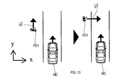
- a pedestrian PD1 walking along the traveling direction of the own vehicle MC may start crossing the road.
- the vehicle width direction component of the movement vector V0 of the pedestrian PD1 before crossing is V0x
- the vehicle width direction component of the movement vector V1 of the pedestrian PD1 at the time of crossing is V1x.
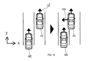
- the front vehicle FC traveling in the adjacent lane of the own vehicle MC interrupts the traveling lane of the own vehicle MC. ..
- the vehicle width direction component of the movement vector V2 of the front vehicle FC before the interruption is V2x
- the vehicle width direction component of the movement vector of the front vehicle FC at the time of interruption is V3x.
- the front vehicle FC traveling in the same lane as the own vehicle MC decelerates.
- the traveling direction component of the moving vector V4 of the front vehicle FC before deceleration is V4y
- the traveling direction component of the moving vector V5 of the front vehicle FC during deceleration is V5y.
- the CPU 21 determines whether or not the behavior of the target has changed based on the difference in the traveling direction component of the movement vector, as in the case where the vehicle in front decelerates.
- the change in the speed of the target includes the case where the side vehicle accelerates at the meeting and the case where a pedestrian near the own vehicle suddenly starts running.
- the CPU 21 determines whether or not the behavior of the target has changed based on the difference in the vehicle width direction components of the movement vector.
- the CPU 21 determines that "the driver does not recognize the nth target” and shifts to S480. Then, when shifting to S480, the CPU 21 increments (that is, 1 addition) the target indication value n and shifts to S420.
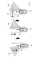
- the driver of the own vehicle MC is visually recognizing the pedestrian PD2 walking on the left side of the own vehicle MC along the traveling direction of the own vehicle MC.
- the fact that the driver of the own vehicle MC is visually recognizing the pedestrian PD2 is shown by the fact that the pedestrian PD2 is included in the gaze range WR1.
- the driver of the own vehicle MC moves the line of sight.
- the gaze range WR2 indicates that the driver of the own vehicle MC has moved the line of sight.
- the driver of the own vehicle MC is in a state where the pedestrian PD2 is not visually recognized.
- the movement vector V11 indicates that the pedestrian PD2 has started crossing the road. Further, it is shown that the driver of the own vehicle MC does not visually recognize the pedestrian PD2 because the pedestrian PD2 is not included in the gaze range WR3.
- a warning sound is output from the speaker 14.
- the vibrator 15 vibrates.
- a warning image AG1 indicating that a pedestrian is approaching is displayed in the HUD display area HR.
- the line LED 11 emits light so that the light LL 11 moves from the left end of the line LED 11 to the region directly below the HUD display region HR.
- FIG. 18 first, it is assumed that the rear vehicle BC is traveling in the same lane as the own vehicle MC.
- the driver of the own vehicle MC is visually recognizing the rear vehicle BC by the fact that the rear vehicle BC is included in the gaze range WR4.
- the driver of the own vehicle MC moves the line of sight.
- the gaze range WR5 indicates that the driver of the own vehicle MC has moved the line of sight.
- the driver of the own vehicle MC is not visually recognizing the rear vehicle BC.
- the own vehicle MC is about to change lanes in a situation where the rear vehicle BC has started overtaking the own vehicle MC.
- the arrow AL12 indicates that the rear vehicle BC has started overtaking the own vehicle MC.
- the arrow AL13 indicates that the own vehicle MC is about to change lanes.
- the fact that the driver of the own vehicle MC does not visually recognize the rear vehicle BC is indicated by the fact that the rear vehicle BC is not included in the gaze range WR6.
- the right rear approach image is displayed in the HUD display area HR, the right rear approach image is displayed on the mirror surface of the right side mirror SM1, a warning sound is output from the speaker 14, and the vibrator is used. 15 vibrates.
- the information presenting device 1 configured in this way is mounted on a vehicle and includes a radar device 2, a DSM 3, and a control device 16.
- the radar device 2 detects an external risk object (for example, a vehicle and a pedestrian) that exists in the vicinity of the own vehicle and may be dangerous to the own vehicle.
- the DSM3 detects the line-of-sight direction of the driver of the own vehicle.
- the control device 16 determines whether or not the driver is aware of the risk object outside the vehicle based on the detection result by the radar device 2 and the detection result by the DSM3.
- the control device 16 presents the vehicle-external risk information regarding the vehicle-external risk object to the driver by the HUD5, the LED indicators 8, 9, 10, the line LEDs 11, 12, 13, the speaker 14, and the vibrator 15. Then, the control device 16 presents the outside risk information to the driver in the case where the driver recognizes the outside risk object and the case where the driver does not recognize the outside risk object. Change with.
- the control device 16 causes, for example, a display device arranged near the risk direction to present the out-of-vehicle risk information.
- the presentation of such out-of-vehicle risk information is a supplementary presentation.
- the control device 16 executes, for example, the following four presentations.
- the first presentation is the output of the warning sound by the speaker 14.
- the second presentation is the generation of vibration by the vibrator 15.
- the third presentation is the display of information indicating the risk direction by a display device located near the driver's gaze direction.
- the fourth presentation is a warning display by a display device located near the risk direction.
- the presentation of such out-of-vehicle risk information is a presentation for enabling the driver to recognize the direction in which the out-of-vehicle risk object exists.
- the information presenting device 1 changes the mode of presenting the out-of-vehicle risk information according to whether or not the driver recognizes the out-of-vehicle risk object.
- the information presenting device 1 emphasizes and presents the out-of-vehicle risk information when the driver does not recognize the out-of-vehicle risk object, and when the driver recognizes the out-of-vehicle risk object.
- the information presenting device 1 presents the out-of-vehicle risk information by suppressing the occurrence of a situation in which the driver feels annoyed without impairing the function of enabling the driver to recognize the out-of-vehicle risk object. can do.
- the control device 16 causes the display device located closest to the risk direction to present the out-of-vehicle risk information, and the driver presents the out-of-vehicle risk object. If the driver is not aware of the risk information, at least the display device arranged in a direction that the driver can recognize is presented with the risk information outside the vehicle. As a result, the information presenting device 1 reduces the frequency with which the outside risk information is presented in the direction of the driver's line of sight when the driver recognizes the outside risk object, and the driver feels annoyed. It is possible to suppress the occurrence of a situation. Further, the information presenting device 1 can make it easier for the driver to recognize the existence of the risk object outside the vehicle when the driver does not recognize the risk object outside the vehicle.
- the control device 16 determines a presentation position for presenting the outside-vehicle risk information and a presentation mode for the outside-vehicle risk information based on the risk direction and the driver's gaze direction, and outside the vehicle at the determined presentation position and presentation mode.
- Present risk information For example, the control device 16 uses the HUD 5 to present information when the risk direction is the front front and the driver's gaze direction is the front front. Further, when the risk direction is the right rear side and the driver's gaze direction is the front front, the control device 16 presents information by using the LED indicator 8, the speaker 14, the vibrator 15, and the HUD 5. In this way, the control device 16 changes the presentation position and the presentation mode based on the risk direction and the gaze direction of the driver to present the information.
- the control device 16 presents guidance information that guides the driver's line of sight in the direction in which the out-of-vehicle risk object exists.
- the control device 16 causes the line LED 13 to emit light so that the light moves from the rear end to the front end of the line LED 13 when the risk direction is the right front side and the driver's gaze direction is the left rear side.
- the line LED 11 is made to emit light so that the light moves from the left end to the right end of the line LED 11. This is a display in which light moves from the direction of the driver's line of sight toward the direction in which the risk object outside the vehicle exists.
- the information presenting device 1 can make it easier for the driver to recognize the direction in which the risk object outside the vehicle exists.
- control device 16 drives in the direction in which the out-of-vehicle risk object exists when the driver changes from the state in which the driver does not recognize the out-of-vehicle risk object to the state in which the driver recognizes the out-of-vehicle risk object.
- the presentation mode in which the outside risk information is presented so that the person can recognize it will be changed to the presentation mode in which the outside risk information is presented as an auxiliary.
- the control device 16 executes the sixth presentation instruction when the driver does not recognize the out-of-vehicle risk object, and changes to the state in which the driver recognizes the out-of-vehicle risk object, the fifth presentation. Execute the instruction.
- the information presenting device 1 can suppress the occurrence of a situation in which information is presented for recognizing the out-of-vehicle risk object even though the driver is aware of the out-of-vehicle risk object. .. Therefore, the information presenting device 1 can further suppress the occurrence of a situation in which the driver feels annoyed.
- the behavior of the out-of-vehicle risk object changed after the driver changed from the state in which the driver was looking at the out-of-vehicle risk object to the state in which the driver was not looking at the out-of-vehicle risk object.
- the driver recognizes the outside risk object even though the driver recognizes the outside risk object when the driver does not see the outside risk object. It is possible to suppress the occurrence of a situation in which it is determined that there is no such thing.
- the information presenting device 1 can suppress the occurrence of inconsistency between the determination result of recognition of the risk object outside the vehicle and the driver's feeling. As a result, the information presenting device 1 can further suppress the occurrence of a situation in which the driver finds the information presentation by the information presenting device 1 annoying.
- the radar device 2 corresponds to the outside risk detection unit
- the DSM3 corresponds to the line-of-sight detection unit
- S410 to S480 correspond to the recognition determination unit and the processing as the recognition determination step
- S10 to S110, S210 to S290 correspond to processing as an information presentation unit and an information presentation step.
- the display device arranged near the risk direction corresponds to the first presenter
- the display device arranged near the driver's gaze direction corresponds to the second presenter
- the information presentation device 1 of the second embodiment is different from the first embodiment in that the recognition determination process is changed.
- the CPU 21 When the recognition determination process of the second embodiment is executed, the CPU 21 first sets the target indication value n provided in the RAM 23 to 1 in S610, as shown in FIG. Next, in S620, the CPU 21 determines in S620 whether or not the target indicator value n is greater than the characteristic characteristic NUM, which indicates the total number of targets currently detected by the radar device 2. Here, when the target indicator value n is larger than the characteristic number NUM, the CPU 21 ends the recognition determination process.
- the CPU 21 determines in S630 whether or not the driver is looking at the nth target based on the detection result of DSM3. ..
- the CPU 21 sets the reduction rate described later in S640 to a first set value (1 [buf / s] in this embodiment]. ), And shift to S670.
- the CPU 21 when the driver is not looking at the nth target, the CPU 21 performs the action of the nth target in S650 in the same manner as in S460 while the driver is not looking at the nth target. Determine if it has changed.
- the CPU 21 shifts to S670.
- the CPU 21 sets the reduction rate to be larger than the first set value in S660 (in the present embodiment, 2 [ Set to buf / s]) and shift to S670.
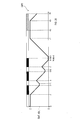
- the CPU 21 calculates the nth attention buffer Buff_n (hereinafter, the nth buffer Buff_n) provided in the RAM 23.
- the graph GR1 is a graph in which the horizontal axis is the time and the vertical axis is the nth buffer Buff_n.
- the driver visually recognizes the nth target at times t0 to t1, t2 to t4, t5 to t7, and t9 to t12. Further, the driver does not visually recognize the nth target at times t1 to t2, t4 to t5, and t7 to t9. Further, the driver visually recognizes the speedometer or the mirror at times t12 to t14.
- the nth buffer Buff_n is reduced at a preset reduction rate (1 [buf / s] or 2 [buf / s] in the present embodiment).
- the nth buffer Buff_n holds the value at the time t2 for a preset delay time (0.1 s in the present embodiment).
- the driver is visually recognizing the nth target. Therefore, when the delay time elapses at time t3, the nth buffer Buff_n increases at a preset rate of increase (1 [buf / s] in this embodiment).
- the driver no longer visually recognizes the nth target, and the state in which the driver does not visually recognize the nth target continues until time t5. Therefore, at times t4 to t5, the nth buffer Buffer_n decreases at a preset reduction rate.
- the n-th buffer Buff_n holds the value at the time t5 for a preset delay time.
- the delay time elapses at time t6 the nth buffer Buffer_n increases at a preset rate of increase.
- the driver no longer visually recognizes the nth target, and the state in which the driver does not visually recognize the nth target continues until time t9. Therefore, the nth buffer Buff_n is reduced at a preset reduction rate. Then, at time t8, when the nth buffer Buff_n becomes 0 [s], the nth buffer Buff_n holds 0 [s] until time t9.
- the nth buffer Buffer_n holds the value at time t9 for a preset delay time. At times t9 to t12, the driver is visually recognizing the nth target. Therefore, when the delay time elapses at time t10, the nth buffer Buffer_n increases at a preset rate of increase.
- the n-th buffer Buff_n holds the value at the time t12 for a preset standby time (1.0 s in the present embodiment). At times t12 to t14, the driver is visually recognizing the speedometer or mirror. Therefore, when the waiting time elapses at time t13, the nth buffer Buffer_n decreases at a preset reduction rate.
- the CPU 21 increases or decreases the nth buffer Buffer_n based on whether or not the driver is visually recognizing the nth target and whether or not the driver is visually recognizing the speedometer or the mirror.
- the nth buffer Buff_n is calculated.
- the CPU 21 determines in S680 whether or not the nth buffer Buffer_n is larger than 0.
- the CPU 21 determines in S690 that "the driver recognizes the nth target", and shifts to S710.
- the CPU 21 determines in S700 that the CPU 21 "does not recognize the nth target", and proceeds to S710.
- the CPU 21 increments the target indication value n and shifts to S620.
- the control device 16 increases the value of the nth buffer Buffer_n at a preset rate of increase, and the driver is outside the vehicle.
- the value of the nth buffer Buff_n is calculated by decreasing the value of the nth buffer Buff_n at a preset reduction rate. Then, the control device 16 determines whether or not the driver is aware of the risk object outside the vehicle based on the value of the nth buffer Buff_n.
- control device 16 changes when the behavior of the out-of-vehicle risk object changes after the driver changes from the state of looking at the out-of-vehicle risk object to the state in which the driver does not see the out-of-vehicle risk object. Increase the rate of decrease.
- the information presentation device 1 changes the behavior of the out-of-vehicle risk object after the driver changes from the state of looking at the out-of-vehicle risk object to the state in which the driver does not see the out-of-vehicle risk object. In some cases, it can be determined that the driver is not aware of the out-of-vehicle risk object.
- the driver recognizes the outside risk object even though the driver recognizes the outside risk object when the driver does not see the outside risk object. It is possible to suppress the occurrence of a situation in which it is determined that there is no such thing. That is, the information presenting device 1 can suppress the occurrence of inconsistency between the determination result of recognition of the risk object outside the vehicle and the driver's feeling. As a result, the information presenting device 1 can further suppress the occurrence of a situation in which the driver finds the information presentation by the information presenting device 1 annoying.
- S610 to S710 correspond to the processing as the recognition determination unit and the recognition determination step.
- the HUD5, the LED indicators 8, 9, 10, the line LEDs 11, 12, 13, the speaker 14, and the vibrator 15 are used as auxiliary devices.
- CID6 or MID7 may be used as an auxiliary device.
- the driver's gaze direction is the driver's smartphone, the driver's smartphone may be made to present the risk information outside the vehicle. Further, when the driver's gaze direction is the passenger, at least one of sound and vibration may be generated.
- the control device 16 and its method described in the present disclosure are provided by a dedicated computer provided by configuring a processor and memory programmed to perform one or more functions embodied by a computer program. It may be realized. Alternatively, the control device 16 and its method described in the present disclosure may be realized by a dedicated computer provided by configuring the processor with one or more dedicated hardware logic circuits. Alternatively, the control device 16 and its method described in the present disclosure is a combination of a processor and memory programmed to perform one or more functions and a processor composed of one or more hardware logic circuits. It may be realized by one or more dedicated computers configured by. The computer program may also be stored on a computer-readable non-transitional tangible recording medium as an instruction executed by the computer. The method for realizing the functions of each part included in the control device 16 does not necessarily include software, and all the functions may be realized by using one or a plurality of hardware.
- a plurality of functions possessed by one component in the above embodiment may be realized by a plurality of components, or one function possessed by one component may be realized by a plurality of components. Further, a plurality of functions possessed by the plurality of components may be realized by one component, or one function realized by the plurality of components may be realized by one component. Further, a part of the configuration of the above embodiment may be omitted. Further, at least a part of the configuration of the above embodiment may be added or replaced with the configuration of the other above embodiment.
- a system having the information presenting device 1 as a component, a program for operating a computer as the information presenting device 1, a non-transitional actual record of a semiconductor memory or the like in which this program is recorded The present disclosure can also be realized in various forms such as a medium and an information presentation method.
Landscapes
- Engineering & Computer Science (AREA)
- Physics & Mathematics (AREA)
- General Physics & Mathematics (AREA)
- Multimedia (AREA)
- Theoretical Computer Science (AREA)
- Mechanical Engineering (AREA)
- Human Computer Interaction (AREA)
- Transportation (AREA)
- Automation & Control Theory (AREA)
- Combustion & Propulsion (AREA)
- Chemical & Material Sciences (AREA)
- Optics & Photonics (AREA)
- Health & Medical Sciences (AREA)
- General Health & Medical Sciences (AREA)
- Ophthalmology & Optometry (AREA)
- Traffic Control Systems (AREA)
- Instrument Panels (AREA)
Abstract
This information presentation device (1) comprises a vehicle-external-risk detection unit (2), a sightline detection unit (3), recognition-determining units (S410 to S480, S610 to S710), and information presentation units (S10 to S110, S210 to S290). The vehicle-external-risk detection unit detects a vehicle-external-risk object present around a vehicle, and pose a danger to the vehicle. The sightline detection unit detects the sightline direction of a driver of the vehicle. The recognition-determining unit determines whether the driver recognizes the vehicle-external-risk object on the basis of the detection results outputted from the vehicle-external-risk detection unit and the sightline detection unit. The information presentation unit changes the presentation mode for presenting the vehicle-external-risk information to the driver between when the driver recognizes the vehicle-external-risk object and when the driver does not recognize the vehicle-external-risk object.
Description
本国際出願は、2019年5月30日に日本国特許庁に出願された日本国特許出願第2019-101357号に基づく優先権を主張するものであり、日本国特許出願第2019-101357号の全内容を参照により本国際出願に援用する。
This international application claims priority based on Japanese Patent Application No. 2019-101357 filed with the Japan Patent Office on May 30, 2019, and Japanese Patent Application No. 2019-101357. The entire contents are incorporated in this international application by reference.
本開示は、車両の運転者に情報を提示する情報提示装置、情報提示方法および情報提示プログラムに関する。
This disclosure relates to an information presentation device, an information presentation method, and an information presentation program that presents information to the driver of a vehicle.
特許文献1には、運転者の視線の動きと障害物とを検出し、運転者の視線から外れた位置に警告を表示した後に、障害物へ視線の動きを誘導するように構成された視線誘導装置が記載されている。
Patent Document 1 is configured to detect the movement of the driver's line of sight and an obstacle, display a warning at a position outside the driver's line of sight, and then guide the movement of the line of sight to the obstacle. Guidance devices are described.
しかし、発明者の詳細な検討の結果、車外のリスクに関する車外リスク情報を運転者に提示する情報提示装置では、運転者がリスクを認識しているにも関わらず車外リスク情報を運転者に提示すると、その情報提示を運転者が煩わしいと感じてしまい、車外リスク情報を提示する機能を運転者が利用しなくなってしまうという課題が見出された。
However, as a result of detailed examination by the inventor, the information presenting device that presents the outside risk information regarding the outside risk to the driver presents the outside risk information to the driver even though the driver is aware of the risk. Then, the driver feels that the presentation of the information is troublesome, and the problem is found that the driver does not use the function of presenting the risk information outside the vehicle.
本開示は、運転者が煩わしいと感じてしまう事態の発生を抑制して車外リスク情報を提示する。
本開示の一態様は、車両に搭載される情報提示装置であって、車外リスク検出部と、視線検出部と、認識判断部と、情報提示部とを備える。 This disclosure suppresses the occurrence of a situation that the driver finds annoying and presents the risk information outside the vehicle.
One aspect of the present disclosure is an information presentation device mounted on a vehicle, which includes an external risk detection unit, a line-of-sight detection unit, a recognition determination unit, and an information presentation unit.
車外リスク検出部は、車両の周辺に存在し、且つ、車両に対して危険となる可能性がある車外リスク対象物を検出するように構成される。視線検出部は、車両の運転者の視線方向を検出するように構成される。
The out-of-vehicle risk detection unit is configured to detect an out-of-vehicle risk object that exists in the vicinity of the vehicle and may be dangerous to the vehicle. The line-of-sight detection unit is configured to detect the line-of-sight direction of the driver of the vehicle.
認識判断部は、車外リスク検出部による検出結果と、視線検出部による検出結果とに基づいて、運転者が車外リスク対象物を認識しているか否かを判断するように構成される。
The recognition judgment unit is configured to determine whether or not the driver recognizes the outside risk object based on the detection result by the outside risk detection unit and the detection result by the line-of-sight detection unit.
情報提示部は、車外リスク対象物に関する車外リスク情報を運転者に対して提示するように構成される。そして情報提示部は、認識判断部による判断結果に基づき、車外リスク情報を運転者に対して提示する提示態様を、運転者が車外リスク対象物を認識している場合と、運転者が車外リスク対象物を認識していない場合とで変化させる。
The information presentation unit is configured to present the outside risk information regarding the outside risk object to the driver. Then, the information presentation unit presents the outside risk information to the driver based on the judgment result by the recognition judgment unit, when the driver recognizes the outside risk object and when the driver recognizes the outside risk object. It changes depending on whether the object is not recognized.
このように構成された本開示の情報提示装置は、車外リスク情報の提示態様を、運転者が車外リスク対象物を認識しているか否かに応じて変化させる。これにより、本開示の情報提示装置は、運転者が車外リスク対象物を認識していない場合には、車外リスク情報を強調して提示し、運転者が車外リスク対象物を認識している場合には、車外リスク情報を強調しないで提示するようにすることができる。すなわち、本開示の情報提示装置は、運転者が車外リスク対象物を認識していない場合には、運転者が車外リスク対象物を認識できるように車外リスク情報を提示し、運転者が車外リスク対象物を認識している場合には、運転者が煩わしいと感じないように車外リスク情報を提示することができる。
The information presenting device of the present disclosure configured in this way changes the presentation mode of the out-of-vehicle risk information according to whether or not the driver is aware of the out-of-vehicle risk object. As a result, the information presenting device of the present disclosure emphasizes and presents the out-of-vehicle risk information when the driver does not recognize the out-of-vehicle risk object, and when the driver recognizes the out-of-vehicle risk object. Can be presented without emphasizing out-of-vehicle risk information. That is, when the driver does not recognize the outside risk object, the information presenting device of the present disclosure presents the outside risk information so that the driver can recognize the outside risk object, and the driver presents the outside risk information. When the object is recognized, the risk information outside the vehicle can be presented so that the driver does not feel annoyed.
これにより、本開示の情報提示装置は、運転者が車外リスク対象物を認識できるようにするという機能を損なうことなく、運転者が煩わしいと感じてしまう事態の発生を抑制して、車外リスク情報を提示することができる。
As a result, the information presenting device of the present disclosure suppresses the occurrence of a situation in which the driver feels annoyed without impairing the function of enabling the driver to recognize the risk object outside the vehicle, and the risk information outside the vehicle. Can be presented.
本開示の別の態様は、車両の運転者に情報を提示する情報提示方法であって、認識判断ステップと、情報提示ステップとを備える。
Another aspect of the present disclosure is an information presentation method for presenting information to the driver of a vehicle, which includes a recognition determination step and an information presentation step.
認識判断ステップは、車外リスク検出部による検出結果と、視線検出部による検出結果とに基づいて、運転者が車外リスク対象物を認識しているか否かを判断する。
The recognition judgment step determines whether or not the driver recognizes the risk object outside the vehicle based on the detection result by the risk detection unit outside the vehicle and the detection result by the line-of-sight detection unit.
情報提示ステップは、車外リスク対象物に関する車外リスク情報を運転者に対して提示する。そして情報提示ステップは、認識判断ステップによる判断結果に基づき、車外リスク情報を運転者に対して提示する提示態様を、運転者が車外リスク対象物を認識している場合と、運転者が車外リスク対象物を認識していない場合とで変化させる。
The information presentation step presents the outside risk information regarding the outside risk object to the driver. Then, in the information presentation step, based on the judgment result of the recognition judgment step, the presentation mode of presenting the outside risk information to the driver is determined when the driver recognizes the outside risk object and when the driver recognizes the outside risk object. It changes depending on whether the object is not recognized.
本開示の情報提示方法は、本開示の情報提示装置にて実行される方法であり、当該方法を実行することで、本開示の情報提示装置と同様の効果を得ることができる。
The information presentation method of the present disclosure is a method executed by the information presentation device of the present disclosure, and by executing the method, the same effect as that of the information presentation device of the present disclosure can be obtained.
本開示の更に別の態様は、車両の運転者に情報を提示するために、コンピュータを、認識判断部、及び、情報提示部として機能させるための情報提示プログラムである。
Yet another aspect of the present disclosure is an information presentation program for causing the computer to function as a recognition judgment unit and an information presentation unit in order to present information to the driver of the vehicle.
本開示の情報提示プログラムによって制御されるコンピュータは、本開示の情報提示装置の一部を構成することができ、本開示の情報提示装置と同様の効果を得ることができる。
The computer controlled by the information presentation program of the present disclosure can form a part of the information presentation device of the present disclosure, and can obtain the same effect as the information presentation device of the present disclosure.
(第1実施形態)
以下に本開示の第1実施形態を図面とともに説明する。 (First Embodiment)
The first embodiment of the present disclosure will be described below together with the drawings.
以下に本開示の第1実施形態を図面とともに説明する。 (First Embodiment)
The first embodiment of the present disclosure will be described below together with the drawings.
本実施形態の情報提示装置1は、車両に搭載され、図1に示すように、レーダ装置2、DSM3、ウインカーセンサ4、HUD5、CID6、MID7、LEDインジケータ8,9,10、ラインLED11,12,13、スピーカ14、バイブレータ15および制御装置16を備える。以下、情報提示装置1を搭載する車両を自車両という。
The information presenting device 1 of the present embodiment is mounted on a vehicle, and as shown in FIG. 1, the radar device 2, the DSM3, the blinker sensor 4, the HUD5, the CID6, the MID7, the LED indicators 8, 9, 10, and the line LEDs 11, 12 , 13, speaker 14, vibrator 15, and control device 16. Hereinafter, the vehicle equipped with the information presentation device 1 is referred to as a own vehicle.
DSMは、Driver Status Monitorの略である。HUDは、Head-Up Displayの略である。CIDは、Center Information Displayの略である。MIDは、Multi Information Displayの略である。LEDは、Light Emitting Diodeの略である。
DSM is an abbreviation for Driver Status Monitor. HUD is an abbreviation for Head-Up Display. CID is an abbreviation for Center Information Display. MID is an abbreviation for Multi Information Display. LED is an abbreviation for Light Emitting Diode.
レーダ装置2は、レーダ波を車両の周囲に向けて送信し、反射したレーダ波を受信することにより、レーダ波を反射した物標までの距離Rと、物標の速度Vと、物標の方位θとを検出する。レーダ装置2は、これらの検出値(R,V,θ)から、横位置x、縦位置y、横速度Vx、縦速度Vyの推定値を算出し、これら推定値(x,y,Vx,Vy)を検出結果として制御装置16へ出力する。
The radar device 2 transmits the radar wave toward the periphery of the vehicle and receives the reflected radar wave, so that the distance R to the target that reflects the radar wave, the speed V of the target, and the target Detects the direction θ. The radar device 2 calculates estimated values of the horizontal position x, the vertical position y, the horizontal speed Vx, and the vertical speed Vy from these detected values (R, V, θ), and these estimated values (x, y, Vx, Vy) is output to the control device 16 as a detection result.
DSM3は、運転者の顔をカメラで撮影し、画像解析により運転者の視線方向を検出する。ウインカーセンサ4は、車両の右ウインカーのオンおよびオフと、左ウインカーのオンおよびオフとを検出する。
DSM3 captures the driver's face with a camera and detects the driver's line-of-sight direction by image analysis. The turn signal sensor 4 detects on and off of the right turn signal of the vehicle and on and off of the left turn signal.
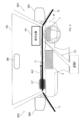
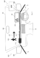
HUD5は、図2に示すように、車両のウインドシールドWSの下方からウインドシールドWSのHUD表示領域HRに向けて、画像を表示するための表示光を照射する。これにより、ウインドシールドWSに虚像が投影され、運転者は、HUD表示領域HRにおいて、その虚像を車両前方の実際の風景に重ねて視認することができる。
As shown in FIG. 2, the HUD 5 irradiates display light for displaying an image from below the windshield WS of the vehicle toward the HUD display area HR of the windshield WS. As a result, a virtual image is projected on the windshield WS, and the driver can visually recognize the virtual image by superimposing it on the actual landscape in front of the vehicle in the HUD display area HR.
CID6は、センタクラスタCCの上方に設置され、表示画面に各種画像を表示する。MID7は、運転席の前方のインストルメントパネルIPに設けられて、表示画面に車両の各種状態を表示する。
CID6 is installed above the center cluster CC and displays various images on the display screen. The MID 7 is provided on the instrument panel IP in front of the driver's seat and displays various states of the vehicle on the display screen.
LEDインジケータ8は、右側サイドミラーSM1の鏡面に設置されている。LEDインジケータ8は、発光により、自車両の右後方からの車両の接近を示す画像(以下、右後方接近画像)を表示する。LEDインジケータ9は、左側のサイドミラーSM2の鏡面に設置されている。LEDインジケータ9は、発光により、自車両の左後方からの車両の接近を示す画像(以下、左後方接近画像)を表示する。LEDインジケータ10は、バックミラーBMの鏡面に設置されている。
The LED indicator 8 is installed on the mirror surface of the right side mirror SM1. The LED indicator 8 emits light to display an image showing the approach of the vehicle from the right rear of the own vehicle (hereinafter, right rear approach image). The LED indicator 9 is installed on the mirror surface of the left side mirror SM2. The LED indicator 9 emits light to display an image showing the approach of the vehicle from the left rear of the own vehicle (hereinafter, left rear approach image). The LED indicator 10 is installed on the mirror surface of the rear-view mirror BM.
ラインLED11,12,13は、複数のLED素子を線状に配列して形成され、複数のLED素子のそれぞれを独立に点灯および消灯することができるように構成されている。ラインLED11は、四角形状のウインドシールドWSの下辺付近において、ウインドシールドWSの下辺に沿って配置される。ラインLED12は、四角形状の運転席側窓WD1の下辺付近において、運転席側窓WD1の下辺に沿って配置される。ラインLED13は、四角形状の助手席側窓WD2の下辺付近において、助手席側窓WD2の下辺に沿って配置される。
The line LEDs 11, 12, and 13 are formed by arranging a plurality of LED elements linearly, and are configured so that each of the plurality of LED elements can be turned on and off independently. The line LED 11 is arranged along the lower side of the windshield WS in the vicinity of the lower side of the rectangular windshield WS. The line LED 12 is arranged near the lower side of the rectangular driver's seat side window WD1 along the lower side of the driver's seat side window WD1. The line LED 13 is arranged near the lower side of the square passenger seat side window WD2 along the lower side of the passenger seat side window WD2.
図1に示すように、スピーカ14は、車室内に設置され、制御装置16から入力された音声電気信号を音声に変換して出力する。
As shown in FIG. 1, the speaker 14 is installed in the vehicle interior, and converts the voice electric signal input from the control device 16 into voice and outputs it.
バイブレータ15は、車室内に設置されている。バイブレータ15は、振動モータを備え、振動モータを駆動することにより、振動を発生させる。
The vibrator 15 is installed in the vehicle interior. The vibrator 15 includes a vibration motor, and generates vibration by driving the vibration motor.
制御装置16は、CPU21、ROM22およびRAM23等を備えたマイクロコンピュータを中心に構成された電子制御装置である。マイクロコンピュータの各種機能は、CPU21が非遷移的実体的記録媒体に格納されたプログラムを実行することにより実現される。この例では、ROM22が、プログラムを格納した非遷移的実体的記録媒体に該当する。また、このプログラムの実行により、プログラムに対応する方法が実行される。なお、CPU21が実行する機能の一部または全部を、一つあるいは複数のIC等によりハードウェア的に構成してもよい。また、制御装置16を構成するマイクロコンピュータの数は1つでも複数でもよい。
The control device 16 is an electronic control device mainly composed of a microcomputer provided with a CPU 21, a ROM 22, a RAM 23, and the like. Various functions of the microcomputer are realized by the CPU 21 executing a program stored in a non-transitional substantive recording medium. In this example, ROM 22 corresponds to a non-transitional substantive recording medium in which a program is stored. In addition, by executing this program, the method corresponding to the program is executed. A part or all of the functions executed by the CPU 21 may be configured in hardware by one or a plurality of ICs or the like. Further, the number of microcomputers constituting the control device 16 may be one or a plurality.
制御装置16は、レーダ装置2、DSM3およびウインカーセンサ4からの入力に基づいて各種処理を実行し、HUD5、CID6、MID7、LEDインジケータ8,9,10、ラインLED11,12,13、スピーカ14およびバイブレータ15を制御する。
The control device 16 executes various processes based on the inputs from the radar device 2, the DSM3, and the blinker sensor 4, and performs various processes, such as the HUD5, CID6, MID7, LED indicators 8, 9, 10, line LEDs 11, 12, 13, and the speaker 14. Controls the vibrator 15.
ここで、自車両の周辺に存在する物体の方向を、以下のように定義する。図3に示すように、自車両を中心とした方向は、自車両の進行方向から時計回りに順に、方向範囲DR1,DR2,DR3,DR4,DR5,DR6,DR7,DR8,DR9,DR10の何れかに分類される。以下、方向範囲DR1を正面前方ともいう。方向範囲DR2を右前方ともいう。方向範囲DR3を右前側方ともいう。方向範囲DR4を右側方ともいう。方向範囲DR5を右後側方ともいう。方向範囲DR6を正面後方ともいう。方向範囲DR7を左後側方ともいう。方向範囲DR8を左側方ともいう。方向範囲DR9を左前側方ともいう。方向範囲DR10を左前方ともいう。
Here, the direction of the objects existing around the own vehicle is defined as follows. As shown in FIG. 3, the direction centered on the own vehicle is any of the direction ranges DR1, DR2, DR3, DR4, DR5, DR6, DR7, DR8, DR9, and DR10 in the clockwise direction from the traveling direction of the own vehicle. It is classified as. Hereinafter, the directional range DR1 is also referred to as a front front. The directional range DR2 is also referred to as the front right. The directional range DR3 is also referred to as the front right side. The direction range DR4 is also referred to as the right side. The directional range DR5 is also referred to as the right rear side. The directional range DR6 is also referred to as front and rear. The directional range DR7 is also referred to as the left rear side. The directional range DR8 is also referred to as the left side. The directional range DR9 is also referred to as the left front side. The directional range DR10 is also referred to as the front left.
次に、制御装置16のCPU21が実行する第1情報提示処理の手順を説明する。第1情報提示処理は、制御装置16の動作中において繰り返し実行される処理である。
Next, the procedure of the first information presentation process executed by the CPU 21 of the control device 16 will be described. The first information presentation process is a process that is repeatedly executed during the operation of the control device 16.
第1情報提示処理が実行されると、CPU21は、図4に示すように、まずS10にて、レーダ装置2の検出結果に基づいて、自車両の後側方(すなわち、方向範囲DR5または方向範囲DR7)に車両が存在するか否かを判断する。ここで、自車両の後側方に車両が存在していない場合には、CPU21は、第1情報提示処理を終了する。一方、自車両の後側方に車両が存在している場合には、CPU21は、S20にて、ウインカーセンサ4の検出結果に基づいて、右ウインカーが点滅しているか否かを判断する。
When the first information presentation process is executed, as shown in FIG. 4, the CPU 21 first in S10, based on the detection result of the radar device 2, the rear side of the own vehicle (that is, the direction range DR5 or the direction). It is determined whether or not a vehicle exists in the range DR7). Here, if the vehicle does not exist on the rear side of the own vehicle, the CPU 21 ends the first information presentation process. On the other hand, when the vehicle is on the rear side of the own vehicle, the CPU 21 determines in S20 whether or not the right blinker is blinking based on the detection result of the blinker sensor 4.
ここで、右ウインカーが点滅している場合には、CPU21は、S30にて、HUD5が右後方接近画像を表示しているか否かを判断する。ここで、HUD5が右後方接近画像を表示している場合には、CPU21は、第1情報提示処理を終了する。一方、HUD5が右後方接近画像を表示していない場合には、CPU21は、S40にて、後述する認識判定処理の判定結果に基づいて、運転者が自車両の後側方の車両を認識しているか否かを判断する。ここで、運転者が自車両の後側方の車両を認識していない場合には、CPU21は、S50にて、第1提示指示を実行して、第1情報提示処理を終了する。第1提示指示では、具体的には、CPU21は、右後方接近画像を表示させる指示をHUD5へ出力し、警告音を示す音声電気信号をスピーカ14へ出力し、振動させる指示をバイブレータ15へ出力し、点滅させる指示をLEDインジケータ8へ出力する。これにより、HUD5は右後方接近画像を表示し、スピーカ14は警告音を出力し、バイブレータ15は振動し、LEDインジケータ8は右後方接近画像を点滅表示する。
Here, when the right turn signal is blinking, the CPU 21 determines in S30 whether or not the HUD 5 is displaying the right rear approach image. Here, when the HUD 5 is displaying the right rear approach image, the CPU 21 ends the first information presentation process. On the other hand, when the HUD 5 does not display the right rear approach image, the CPU 21 recognizes the vehicle on the rear side of the own vehicle in S40 based on the determination result of the recognition determination process described later. Judge whether or not it is. Here, if the driver does not recognize the vehicle on the rear side of the own vehicle, the CPU 21 executes the first presentation instruction in S50 and ends the first information presentation process. In the first presentation instruction, specifically, the CPU 21 outputs an instruction to display a right rear approach image to the HUD 5, outputs a voice electric signal indicating a warning sound to the speaker 14, and outputs an instruction to vibrate to the vibrator 15. Then, an instruction to blink is output to the LED indicator 8. As a result, the HUD 5 displays the right rear approach image, the speaker 14 outputs a warning sound, the vibrator 15 vibrates, and the LED indicator 8 blinks the right rear approach image.
一方、運転者が自車両の後側方の車両を認識している場合には、CPU21は、S60にて、第2提示指示を実行して、第1情報提示処理を終了する。第2提示指示では、具体的には、CPU21は、点灯させる指示をLEDインジケータ8へ出力する。これにより、LEDインジケータ8は右後方接近画像を点灯表示する。
On the other hand, when the driver recognizes the vehicle on the rear side of the own vehicle, the CPU 21 executes the second presentation instruction in S60 to end the first information presentation process. In the second presentation instruction, specifically, the CPU 21 outputs an instruction to turn on the LED indicator 8. As a result, the LED indicator 8 lights and displays the right rear approach image.
またS20にて、右ウインカーが点滅していない場合には、CPU21は、S70にて、ウインカーセンサ4の検出結果に基づいて、左ウインカーが点滅しているか否かを判断する。
If the right blinker is not blinking in S20, the CPU 21 determines in S70 whether or not the left blinker is blinking based on the detection result of the blinker sensor 4.
ここで、左ウインカーが点滅していない場合には、第1情報提示処理を終了する。一方、左ウインカーが点滅している場合には、CPU21は、S80にて、HUD5が左後方接近画像を表示しているか否かを判断する。ここで、HUD5が左後方接近画像を表示している場合には、CPU21は、第1情報提示処理を終了する。一方、HUD5が左後方接近画像を表示していない場合には、CPU21は、S90にて、認識判定処理の判定結果に基づいて、運転者が自車両の後側方の車両を認識しているか否かを判断する。ここで、運転者が自車両の後側方の車両を認識していない場合には、CPU21は、S100にて、第3提示指示を実行して、第1情報提示処理を終了する。第3提示指示では、具体的には、CPU21は、左後方接近画像を表示させる指示をHUD5へ出力し、警告音を示す音声電気信号をスピーカ14へ出力し、振動させる指示をバイブレータ15へ出力し、点滅させる指示をLEDインジケータ9へ出力する。これにより、HUD5は左後方接近画像を表示し、スピーカ14は警告音を出力し、バイブレータ15は振動し、LEDインジケータ9は左後方接近画像を点滅表示する。
Here, if the left turn signal is not blinking, the first information presentation process is terminated. On the other hand, when the left turn signal is blinking, the CPU 21 determines in S80 whether or not the HUD 5 is displaying the left rear approach image. Here, when the HUD 5 is displaying the left rear approach image, the CPU 21 ends the first information presentation process. On the other hand, when the HUD 5 does not display the left rear approach image, is the CPU 21 recognizing the vehicle on the rear side of the own vehicle based on the determination result of the recognition determination process in S90? Judge whether or not. Here, if the driver does not recognize the vehicle on the rear side of the own vehicle, the CPU 21 executes the third presentation instruction in S100 to end the first information presentation process. In the third presentation instruction, specifically, the CPU 21 outputs an instruction to display a left rear approach image to the HUD 5, outputs a voice electric signal indicating a warning sound to the speaker 14, and outputs an instruction to vibrate to the vibrator 15. Then, an instruction to blink is output to the LED indicator 9. As a result, the HUD 5 displays the left rear approach image, the speaker 14 outputs a warning sound, the vibrator 15 vibrates, and the LED indicator 9 blinks the left rear approach image.
一方、運転者が自車両の後側方の車両を認識している場合には、CPU21は、S110にて、第4提示指示を実行して、第1情報提示処理を終了する。第4提示指示では、具体的には、CPU21は、点灯させる指示をLEDインジケータ9へ出力する。これにより、LEDインジケータ9は左後方接近画像を点灯表示する。
On the other hand, when the driver recognizes the vehicle on the rear side of the own vehicle, the CPU 21 executes the fourth presentation instruction in S110 to end the first information presentation process. In the fourth presentation instruction, specifically, the CPU 21 outputs an instruction to turn on the LED indicator 9. As a result, the LED indicator 9 lights and displays the left rear approach image.
第1情報提示処理では、CPU21は、例えば、図5に示すように、自車両MCの右後側方に車両RCが存在しており、且つ、自車両MCが右側へ車線変更するために自車両MCの右ウインカーが点滅している場合において、各種指示を実行するか否かを判断する。図5では、ウインカー光WL1,WL2により、自車両MCの右ウインカーが点滅していることを示し、矢印AL1により、自車両MCが右側へ車線変更することを示している。
In the first information presentation process, for example, as shown in FIG. 5, the CPU 21 has a vehicle RC on the right rear side of the own vehicle MC, and the own vehicle MC changes lanes to the right. When the right turn signal of the vehicle MC is blinking, it is determined whether or not to execute various instructions. In FIG. 5, the blinker lights WL1 and WL2 indicate that the right blinker of the own vehicle MC is blinking, and the arrow AL1 indicates that the own vehicle MC changes lanes to the right.
次に、制御装置16のCPU21が実行する第2情報提示処理の手順を説明する。第2情報提示処理は、制御装置16の動作中において繰り返し実行される処理である。
Next, the procedure of the second information presentation process executed by the CPU 21 of the control device 16 will be described. The second information presentation process is a process that is repeatedly executed during the operation of the control device 16.
第2情報提示処理が実行されると、CPU21は、図6に示すように、まずS210にて、レーダ装置2の検出結果に基づいて、自車両の周囲に物標が存在するか否かを判断する。ここで、自車両の周囲に物標が存在していない場合には、CPU21は、第2情報提示処理を終了する。一方、自車両の周囲に物標が存在している場合には、CPU21は、S220にて、レーダ装置2の検出結果に基づいて、S210において判断対象となった物標(以下、対象物標)と自車両との衝突予測時間TTCを算出する。TTCは、Time To Collisionの略である。
When the second information presentation process is executed, as shown in FIG. 6, the CPU 21 first determines in S210 whether or not a target exists around the own vehicle based on the detection result of the radar device 2. to decide. Here, if there is no target around the own vehicle, the CPU 21 ends the second information presentation process. On the other hand, when there is a target around the own vehicle, the CPU 21 determines the target in S210 based on the detection result of the radar device 2 in S220 (hereinafter, the target target). ) And the collision prediction time TTC with the own vehicle are calculated. TTC is an abbreviation for Time To Collision.
そしてCPU21は、S230にて、S220で算出した衝突予測時間TTCが予め設定された危険度判定値J1以下であるか否かを判断する。すなわち、S230では、CPU21は、衝突予測時間TTCが危険度判定値J1以下である場合に、危険度が高いと判断する。一方、CPU21は、衝突予測時間TTCが危険度判定値J1を超えている場合に、危険度が低いと判断する。
Then, in S230, the CPU 21 determines whether or not the collision prediction time TTC calculated in S220 is equal to or less than the preset risk determination value J1. That is, in S230, the CPU 21 determines that the risk level is high when the collision prediction time TTC is equal to or less than the risk level determination value J1. On the other hand, when the collision prediction time TTC exceeds the risk determination value J1, the CPU 21 determines that the risk is low.
ここで、衝突予測時間TTCが危険度判定値J1以下である場合には、CPU21は、S240にて、後述する認識判定処理の判定結果に基づいて、運転者が、対象物標を認識しているか否かを判断する。
Here, when the collision prediction time TTC is equal to or less than the risk determination value J1, the CPU 21 recognizes the target target in S240 based on the determination result of the recognition determination process described later. Judge whether or not.
ここで、運転者が対象物標を認識している場合には、CPU21は、S250にて、第5提示指示を実行して、第2情報提示処理を終了する。第5提示指示では、具体的には、CPU21は、対象物標が存在する方向(以下、リスク方向)の近くに配置されている表示デバイスへ提示指示を出力する。例えば、自車両の右側方(すなわち、方向範囲DR4)に対象物標が存在しており、且つ、運転者が対象物標を認識している場合には、CPU21は、運転者の右側に設置されているラインLED12を点滅させる。
Here, when the driver recognizes the target target, the CPU 21 executes the fifth presentation instruction in S250 to end the second information presentation process. In the fifth presentation instruction, specifically, the CPU 21 outputs the presentation instruction to the display device arranged near the direction in which the target target exists (hereinafter, the risk direction). For example, if the target target exists on the right side of the own vehicle (that is, the direction range DR4) and the driver recognizes the target target, the CPU 21 is installed on the right side of the driver. The line LED 12 is blinked.
一方、運転者が対象物標を認識していない場合には、CPU21は、S260にて、第6提示指示を実行して、第2情報提示処理を終了する。第6提示指示では、具体的には、CPU21は、以下の四つの指示を出力する。一つ目の指示として、CPU21は、警告音を示す音声電気信号をスピーカ14へ出力する。二つ目の指示として、CPU21は、高周波数で振動させる指示をバイブレータ15へ出力する。三つ目の指示として、CPU21は、運転者の注視方向の近くに配置されている表示デバイスへ、リスク方向を表す情報を表示させる指示を出力する。四つ目の指示として、CPU21は、リスク方向の近くに配置されている表示デバイスへ、注意喚起の表示(例えば、LEDまたはアイコンの点滅)をさせる指示を出力する。
On the other hand, when the driver does not recognize the target target, the CPU 21 executes the sixth presentation instruction in S260 to end the second information presentation process. Specifically, in the sixth presentation instruction, the CPU 21 outputs the following four instructions. As the first instruction, the CPU 21 outputs a voice electric signal indicating a warning sound to the speaker 14. As the second instruction, the CPU 21 outputs an instruction to vibrate at a high frequency to the vibrator 15. As a third instruction, the CPU 21 outputs an instruction for displaying information indicating the risk direction to a display device arranged near the driver's gaze direction. As a fourth instruction, the CPU 21 outputs an instruction to display a warning (for example, blinking an LED or an icon) to a display device located near the risk direction.
またS230にて、衝突予測時間TTCが危険度判定値J1を超えている場合には、CPU21は、S270にて、認識判定処理の判定結果に基づいて、運転者が、対象物標を認識しているか否かを判断する。
Further, in S230, when the collision prediction time TTC exceeds the risk determination value J1, the CPU 21 recognizes the target target in S270 based on the determination result of the recognition determination process. Judge whether or not it is.
ここで、運転者が対象物標を認識している場合には、CPU21は、S280にて、第7提示指示を実行して、第2情報提示処理を終了する。第7提示指示では、具体的には、CPU21は、リスク方向の近くに配置されている表示デバイスへ提示指示を出力する。例えば、自車両の右側方(すなわち、方向範囲DR4)に対象物標が存在しており、且つ、運転者が対象物標を認識している場合には、CPU21は、運転者の右側に配置されているラインLED12を点灯させる。
Here, when the driver recognizes the target target, the CPU 21 executes the seventh presentation instruction in S280 to end the second information presentation process. In the seventh presentation instruction, specifically, the CPU 21 outputs the presentation instruction to the display device arranged near the risk direction. For example, if the target target exists on the right side of the own vehicle (that is, the direction range DR4) and the driver recognizes the target target, the CPU 21 is arranged on the right side of the driver. The line LED 12 is turned on.
一方、運転者が対象物標を認識していない場合には、CPU21は、S290にて、第8提示指示を実行して、第2情報提示処理を終了する。第8提示指示では、具体的には、CPU21は、以下の四つの指示を出力する。一つ目の指示として、CPU21は、警告音を示す音声電気信号をスピーカ14へ出力する。二つ目の指示として、CPU21は、低周波数で振動させる指示をバイブレータ15へ出力する。三つ目の指示として、CPU21は、運転者の注視方向の近くに配置されている表示デバイスへ、リスク方向を表す情報を表示させる指示を出力する。四つ目の指示として、CPU21は、リスク方向の近くに配置されている表示デバイスへ、注意喚起の表示(例えば、LEDまたはアイコンの点灯)をさせる指示を出力する。
On the other hand, if the driver does not recognize the target target, the CPU 21 executes the eighth presentation instruction in S290 to end the second information presentation process. Specifically, in the eighth presentation instruction, the CPU 21 outputs the following four instructions. As the first instruction, the CPU 21 outputs a voice electric signal indicating a warning sound to the speaker 14. As the second instruction, the CPU 21 outputs an instruction to vibrate at a low frequency to the vibrator 15. As a third instruction, the CPU 21 outputs an instruction for displaying information indicating the risk direction to a display device arranged near the driver's gaze direction. As a fourth instruction, the CPU 21 outputs an instruction to display a warning (for example, lighting an LED or an icon) to a display device located near the risk direction.
次に、第1情報提示処理の第1,3提示指示および第2情報提示処理の第6,8提示指示において提示に使用するデバイスの組み合わせを説明する。
Next, the combination of devices used for presentation in the first and third presentation instructions of the first information presentation process and the sixth and eighth presentation instructions of the second information presentation process will be described.
図7に示すように、第6,8提示指示における提示は、基準デバイスと補助デバイスとの組み合わせによって行われる。図7の各欄に記載されている数字は、情報提示装置1の構成要素の符号である。例えば、「5」は、HUD5であることを示す。「11」は、ラインLED11であることを示す。基準デバイスは、リスク方向に基づいて選択される。補助デバイスは、運転者の注視方向に基づいて選択される。
As shown in FIG. 7, the presentation in the 6th and 8th presentation instructions is performed by the combination of the reference device and the auxiliary device. The numbers shown in each column of FIG. 7 are the codes of the components of the information presentation device 1. For example, "5" indicates HUD5. "11" indicates that it is a line LED 11. The reference device is selected based on the risk direction. Auxiliary devices are selected based on the driver's gaze direction.
リスク方向が正面前方であるときの基準デバイスは、HUD5である。リスク方向が右前方、左前方、右前側方および左前側方であるときの基準デバイスは、ラインLED11である。リスク方向が右側方であるときの基準デバイスは、ラインLED12である。リスク方向が左側方であるときの基準デバイスは、ラインLED13である。リスク方向が右後側方であるときの基準デバイスは、LEDインジケータ8である。リスク方向が左後側方であるときの基準デバイスは、LEDインジケータ9である。リスク方向が正面後方であるときの基準デバイスは、LEDインジケータ10である。
The reference device when the risk direction is front and front is HUD5. The reference device when the risk directions are front right, front left, front right side and front left side is the line LED 11. The reference device when the risk direction is to the right is the line LED 12. The reference device when the risk direction is to the left is the line LED 13. The reference device when the risk direction is right rear side is the LED indicator 8. The reference device when the risk direction is left rear side is the LED indicator 9. The reference device when the risk direction is front-back is the LED indicator 10.
また、運転者の注視方向が正面前方であるときの補助デバイスは、スピーカ14、バイブレータ15およびHUD5である。但し、リスク方向が正面前方である場合には、補助デバイスは利用されない。
Further, the auxiliary devices when the driver's gaze direction is the front front are the speaker 14, the vibrator 15, and the HUD 5. However, if the risk direction is front and front, the auxiliary device is not used.
運転者の注視方向が右前方であるときの補助デバイスは、スピーカ14、バイブレータ15およびラインLED11である。但し、リスク方向が右前方である場合には、補助デバイスは利用されない。
Auxiliary devices when the driver's gaze direction is forward right are the speaker 14, the vibrator 15, and the line LED 11. However, if the risk direction is to the right front, the auxiliary device is not used.
運転者の注視方向が左前方であるときの補助デバイスは、スピーカ14、バイブレータ15およびラインLED11である。但し、リスク方向が左前方である場合には、補助デバイスは利用されない。
Auxiliary devices when the driver's gaze direction is left front are the speaker 14, the vibrator 15, and the line LED 11. However, if the risk direction is to the left front, the auxiliary device is not used.
運転者の注視方向が右前側方であるときの補助デバイスは、スピーカ14、バイブレータ15およびラインLED11である。但し、リスク方向が右前側方である場合には、補助デバイスは利用されない。
The auxiliary devices when the driver's gaze direction is the right front side are the speaker 14, the vibrator 15, and the line LED 11. However, if the risk direction is to the right front side, the auxiliary device is not used.
運転者の注視方向が左前側方であるときの補助デバイスは、スピーカ14、バイブレータ15およびラインLED11である。但し、リスク方向が左前側方である場合には、補助デバイスは利用されない。
The auxiliary devices when the driver's gaze direction is the left front side are the speaker 14, the vibrator 15, and the line LED 11. However, if the risk direction is the left front side, the auxiliary device is not used.
運転者の注視方向が右側方であるときの補助デバイスは、スピーカ14、バイブレータ15およびラインLED12である。但し、リスク方向が右側方である場合には、補助デバイスは利用されない。
Auxiliary devices when the driver's gaze direction is to the right are the speaker 14, the vibrator 15, and the line LED 12. However, if the risk direction is to the right, the auxiliary device will not be used.
運転者の注視方向が左側方であるときの補助デバイスは、スピーカ14、バイブレータ15およびラインLED13である。但し、リスク方向が左側方である場合には、補助デバイスは利用されない。
Auxiliary devices when the driver's gaze direction is to the left are the speaker 14, the vibrator 15, and the line LED 13. However, if the risk direction is to the left, the auxiliary device will not be used.
運転者の注視方向が右後側方であるときの補助デバイスは、スピーカ14、バイブレータ15およびラインLED12である。但し、リスク方向が右後側方である場合には、補助デバイスは利用されない。
Auxiliary devices when the driver's gaze direction is to the right rear side are the speaker 14, the vibrator 15, and the line LED 12. However, if the risk direction is to the right rear side, the auxiliary device is not used.
運転者の注視方向が左後側方であるときの補助デバイスは、スピーカ14、バイブレータ15およびラインLED13である。但し、リスク方向が左後側方である場合には、補助デバイスは利用されない。
The auxiliary devices when the driver's gaze direction is the left rear side are the speaker 14, the vibrator 15, and the line LED 13. However, if the risk direction is left rear side, the auxiliary device is not used.
運転者の注視方向が正面後方であるときの補助デバイスは、スピーカ14、バイブレータ15およびHUD5である。但し、リスク方向が正面後方である場合には、補助デバイスは利用されない。更に、リスク方向が正面前方である場合には、補助デバイスとしてHUD5が利用されない。この場合には、スピーカ14による警告音とバイブレータ15による振動により、まず、運転者を前方に向かせて、HUD5でリスク方向に誘導する。
Auxiliary devices when the driver's gaze direction is front and rear are the speaker 14, the vibrator 15, and the HUD 5. However, if the risk direction is front and rear, the auxiliary device is not used. Further, when the risk direction is front front, HUD5 is not used as an auxiliary device. In this case, the warning sound from the speaker 14 and the vibration from the vibrator 15 first turn the driver forward and guide the driver in the risk direction with the HUD 5.
例えば欄C1は、リスク方向が正面前方であり、運転者の注視方向が正面前方であるときの補助デバイスを示す。欄C1には、「none」と記載されているため、補助デバイスは利用されない。すなわち、基準デバイスであるHUD5が利用される。この場合には、例えば、図8に示すように、HUD表示領域HRに「前方注意」が表示される。
For example, column C1 indicates an auxiliary device when the risk direction is the front front and the driver's gaze direction is the front front. Since the column C1 describes "none", the auxiliary device is not used. That is, the reference device HUD5 is used. In this case, for example, as shown in FIG. 8, "forward attention" is displayed in the HUD display area HR.
また欄C2は、リスク方向が右後側方であり、運転者の注視方向が正面前方であるときの補助デバイスを示す。欄C2には、「+14/15+5」と記載されているため、補助デバイスとして、スピーカ14、バイブレータ15およびHUD5が利用される。そして、基準デバイスとして、LEDインジケータ8が利用される。この場合には、例えば、図9に示すように、HUD表示領域HRに右後方接近画像が表示され、右側サイドミラーSM1の鏡面に右後方接近画像が表示され、スピーカ14から警告音が出力される。また、バイブレータ15が振動する。
In addition, column C2 indicates an auxiliary device when the risk direction is the right rear side and the driver's gaze direction is the front front. Since "+ 14/15 + 5" is described in column C2, the speaker 14, the vibrator 15, and the HUD 5 are used as auxiliary devices. Then, the LED indicator 8 is used as a reference device. In this case, for example, as shown in FIG. 9, a right rear approach image is displayed in the HUD display area HR, a right rear approach image is displayed on the mirror surface of the right side mirror SM1, and a warning sound is output from the speaker 14. To. In addition, the vibrator 15 vibrates.
また欄C3は、リスク方向が正面前方であり、運転者の注視方向が左前側方であるときの補助デバイスを示す。欄C3には、「+14/15+11」と記載されているため、補助デバイスとして、スピーカ14、バイブレータ15およびラインLED11が利用される。そして、基準デバイスとして、HUD5が利用される。この場合には、例えば、図10に示すように、HUD表示領域HRに「前方注意」が表示され、スピーカ14から警告音が出力される。また、バイブレータ15が振動する。さらにラインLED11は、矢印AL2で示すように、光LL1がラインLED11の左端からHUD表示領域HRの直下の領域まで移動するように発光する。
Column C3 indicates an auxiliary device when the risk direction is the front front and the driver's gaze direction is the left front side. Since “+14 / 15 + 11” is described in column C3, the speaker 14, the vibrator 15, and the line LED 11 are used as auxiliary devices. Then, HUD5 is used as a reference device. In this case, for example, as shown in FIG. 10, "forward attention" is displayed in the HUD display area HR, and a warning sound is output from the speaker 14. In addition, the vibrator 15 vibrates. Further, the line LED 11 emits light so that the light LL1 moves from the left end of the line LED 11 to the region directly below the HUD display region HR, as shown by the arrow AL2.
また欄C4は、リスク方向が右前側方であり、運転者の注視方向が左後側方であるときの補助デバイスを示す。欄C4には、「+14/15+13」と記載されているため、補助デバイスとして、スピーカ14、バイブレータ15およびラインLED13が利用される。そして、基準デバイスとして、ラインLED11が利用される。この場合には、例えば、図11に示すように、スピーカ14から警告音が出力される。また、バイブレータ15が振動する。さらにラインLED13は、矢印AL3で示すように、光LL2がラインLED13の後端から前端まで移動するように発光する。そして、光LL2がラインLED13の前端に到達すると、ラインLED11は、矢印AL4で示すように、光LL3がラインLED11の左端から右端まで移動するように発光する。なお、運転者から見て、物標がラインLED11の端部とは異なる位置に存在する場合には、ラインLED11の光は必ずしも端部まで移動しなくてもよい(すなわち、物標の付近で光の位置を止めてよい)。また、HUD表示領域HRに情報が表示される場合は、物標の位置でなくHUD表示領域HRへ視線を誘導するようにしてもよい。
In addition, column C4 indicates an auxiliary device when the risk direction is the right front side and the driver's gaze direction is the left rear side. Since "+ 14/15 + 13" is described in column C4, the speaker 14, the vibrator 15, and the line LED 13 are used as auxiliary devices. Then, the line LED 11 is used as a reference device. In this case, for example, as shown in FIG. 11, a warning sound is output from the speaker 14. In addition, the vibrator 15 vibrates. Further, the line LED 13 emits light so that the light LL2 moves from the rear end to the front end of the line LED 13, as indicated by the arrow AL3. Then, when the light LL2 reaches the front end of the line LED 13, the line LED 11 emits light so that the light LL3 moves from the left end to the right end of the line LED 11 as indicated by the arrow AL4. When the target is located at a position different from the end of the line LED 11 as seen from the driver, the light of the line LED 11 does not necessarily have to move to the end (that is, in the vicinity of the target). You may stop the position of the light). Further, when the information is displayed in the HUD display area HR, the line of sight may be guided to the HUD display area HR instead of the position of the target.
次に、制御装置16のCPU21が実行する認識判定処理の手順を説明する。認識判定処理は、制御装置16の動作中において繰り返し実行される処理である。
Next, the procedure of the recognition determination process executed by the CPU 21 of the control device 16 will be described. The recognition determination process is a process that is repeatedly executed during the operation of the control device 16.
認識判定処理が実行されると、CPU21は、図12に示すように、まずS410にて、RAM23に設けられた物標指示値nを1に設定する。次にCPU21は、S420にて、物標指示値nが、レーダ装置2が現時点で検出している物標の全数を示す物標数NUMより大きいか否かを判断する。ここで、物標指示値nが物標数NUMより大きい場合には、CPU21は、認識判定処理を終了する。
When the recognition determination process is executed, the CPU 21 first sets the target indication value n provided in the RAM 23 to 1 in S410, as shown in FIG. Next, in S420, the CPU 21 determines in S420 whether or not the target indicator value n is greater than the characteristic characteristic NUM, which indicates the total number of the targets currently detected by the radar device 2. Here, when the target indicator value n is larger than the characteristic number NUM, the CPU 21 ends the recognition determination process.
一方、物標指示値nが物標数NUM以下である場合には、CPU21は、S430にて、DSM3の検出結果に基づいて、運転者が第n物標を見ているか否かを判断する。ここで、運転者が第n物標を見ている場合には、CPU21は、S440にて、「運転者は第n物標を認識している」と判定し、S480に移行する。
On the other hand, when the target indicator value n is equal to or less than the characteristic characteristic NUM, the CPU 21 determines in S430 whether or not the driver is looking at the nth target based on the detection result of DSM3. .. Here, when the driver is looking at the nth target, the CPU 21 determines in S440 that "the driver is aware of the nth target" and shifts to S480.
一方、運転者が第n物標を見ていない場合には、CPU21は、S450にて、運転者が第n物標を見てから予め設定された認識判定時間J2(本実施形態では、例えば5秒)が経過したか否かを判断する。
On the other hand, when the driver is not looking at the nth target, the CPU 21 uses S450 to set a preset recognition determination time J2 (for example, in the present embodiment) after the driver looks at the nth target. It is determined whether or not 5 seconds) has passed.
ここで、認識判定時間J2が経過した場合には、CPU21は、S470に移行する。一方、認識判定時間J2が経過していない場合には、CPU21は、S460にて、運転者が第n物標を見ていない間に第n物標の行動が変化したか否かを判断する。具体的には、CPU21は、物標の移動方向、物標と自車両との相対位置、および、物標の速度の少なくとも一つが変化した場合に、物標の行動が変化したと判断する。
Here, when the recognition determination time J2 has elapsed, the CPU 21 shifts to S470. On the other hand, when the recognition determination time J2 has not elapsed, the CPU 21 determines in S460 whether or not the behavior of the nth target has changed while the driver is not looking at the nth target. .. Specifically, the CPU 21 determines that the behavior of the target has changed when at least one of the moving direction of the target, the relative position between the target and the own vehicle, and the speed of the target changes.
物標の移動方向の変化としては、例えば図13に示すように、自車両MCの進行方向に沿って歩いている歩行者PD1が道路の横断を開始した場合が挙げられる。ここで、横断前における歩行者PD1の移動ベクトルV0の車幅方向成分をV0xとし、横断時における歩行者PD1の移動ベクトルV1の車幅方向成分をV1xとする。CPU21は、(V1x-V0x)が予め設定された第1変化判定値より大きくなった場合に、物標の行動が変化したと判断する。
As a change in the moving direction of the target, for example, as shown in FIG. 13, a pedestrian PD1 walking along the traveling direction of the own vehicle MC may start crossing the road. Here, the vehicle width direction component of the movement vector V0 of the pedestrian PD1 before crossing is V0x, and the vehicle width direction component of the movement vector V1 of the pedestrian PD1 at the time of crossing is V1x. When (V1x-V0x) becomes larger than the preset first change determination value, the CPU 21 determines that the behavior of the target has changed.
また、物標の移動方向の変化としては、例えば図14に示すように、自車両MCの隣接車線を走行している前方車両FCが、自車両MCの走行車線に割り込んでくる場合が挙げられる。ここで、割り込み前における前方車両FCの移動ベクトルV2の車幅方向成分をV2xとし、割り込み時における前方車両FCの移動ベクトルの車幅方向成分をV3xとする。CPU21は、(V3x-V2x)が予め設定された第2変化判定値より大きくなった場合に、物標の行動が変化したと判断する。
Further, as a change in the moving direction of the target, for example, as shown in FIG. 14, there is a case where the front vehicle FC traveling in the adjacent lane of the own vehicle MC interrupts the traveling lane of the own vehicle MC. .. Here, the vehicle width direction component of the movement vector V2 of the front vehicle FC before the interruption is V2x, and the vehicle width direction component of the movement vector of the front vehicle FC at the time of interruption is V3x. When (V3x-V2x) becomes larger than the preset second change determination value, the CPU 21 determines that the behavior of the target has changed.
また、物標の移動方向の変化としては、自車両と同一車線にいた後方車両が、隣接車線に移動し、自車両に接近してくる場合が挙げられる。
In addition, as a change in the moving direction of the target, there is a case where a rear vehicle that was in the same lane as the own vehicle moves to the adjacent lane and approaches the own vehicle.
物標の速度の変化としては、例えば図15に示すように、自車両MCと同一車線を走行している前方車両FCが減速する場合が挙げられる。ここで、減速前における前方車両FCの移動ベクトルV4の進行方向成分をV4yとし、減速時における前方車両FCの移動ベクトルV5の進行方向成分をV5yとする。CPU21は、(V5y-V4y)が予め設定された第3変化判定値より大きくなった場合に、物標の行動が変化したと判断する。
As a change in the speed of the target, for example, as shown in FIG. 15, there is a case where the front vehicle FC traveling in the same lane as the own vehicle MC decelerates. Here, the traveling direction component of the moving vector V4 of the front vehicle FC before deceleration is V4y, and the traveling direction component of the moving vector V5 of the front vehicle FC during deceleration is V5y. When (V5y-V4y) becomes larger than the preset third change determination value, the CPU 21 determines that the behavior of the target has changed.
また、物標の速度の変化としては、自車両の後側方に存在する車両が加速して自車両に接近してくる場合が挙げられる。この場合には、CPU21は、前方車両が減速する場合と同様に、移動ベクトルの進行方向成分の差分により、物標の行動が変化したか否かを判断する。
In addition, as a change in the speed of the target, there is a case where the vehicle existing on the rear side of the own vehicle accelerates and approaches the own vehicle. In this case, the CPU 21 determines whether or not the behavior of the target has changed based on the difference in the traveling direction component of the movement vector, as in the case where the vehicle in front decelerates.
また、物標の速度の変化としては、出会頭で側方車が加速してくる場合、および、自車両付近の歩行者が急に走り出す場合が挙げられる。この場合には、CPU21は、移動ベクトルの車幅方向成分の差分により、物標の行動が変化したか否かを判断する。
In addition, the change in the speed of the target includes the case where the side vehicle accelerates at the meeting and the case where a pedestrian near the own vehicle suddenly starts running. In this case, the CPU 21 determines whether or not the behavior of the target has changed based on the difference in the vehicle width direction components of the movement vector.
そして、S460にて、第n物標の行動が変化していないと判断した場合には、CPU21は、図12に示すように、S440に移行する。一方、第n物標の行動が変化したと判断した場合には、CPU21は、S470に移行する。
Then, when it is determined in S460 that the behavior of the nth target has not changed, the CPU 21 shifts to S440 as shown in FIG. On the other hand, when it is determined that the behavior of the nth target has changed, the CPU 21 shifts to S470.
そして470に移行すると、CPU21は、「運転者は第n物標を認識していない」と判定し、S480に移行する。そしてS480に移行すると、CPU21は、物標指示値nをインクリメント(すなわち、1加算)して、S420に移行する。
Then, when shifting to 470, the CPU 21 determines that "the driver does not recognize the nth target" and shifts to S480. Then, when shifting to S480, the CPU 21 increments (that is, 1 addition) the target indication value n and shifts to S420.
次に、情報提示装置1による情報提示の具体例を説明する。
Next, a specific example of information presentation by the information presentation device 1 will be described.
図16に示すように、まず、自車両MCの進行方向に沿って自車両MCの左側を歩いている歩行者PD2を自車両MCの運転者が視認しているとする。図16では、自車両MCの運転者が歩行者PD2を視認していることを、注視範囲WR1内に歩行者PD2が含まれていることにより示している。
As shown in FIG. 16, first, it is assumed that the driver of the own vehicle MC is visually recognizing the pedestrian PD2 walking on the left side of the own vehicle MC along the traveling direction of the own vehicle MC. In FIG. 16, the fact that the driver of the own vehicle MC is visually recognizing the pedestrian PD2 is shown by the fact that the pedestrian PD2 is included in the gaze range WR1.
その後、自車両MCの運転者が視線を移動させる。図16では、自車両MCの運転者が視線を移動させたことを、注視範囲WR2により示している。これにより、自車両MCの運転者が歩行者PD2を視認していない状態となる。
After that, the driver of the own vehicle MC moves the line of sight. In FIG. 16, the gaze range WR2 indicates that the driver of the own vehicle MC has moved the line of sight. As a result, the driver of the own vehicle MC is in a state where the pedestrian PD2 is not visually recognized.
そして、その直後に、歩行者PD2が道路の横断を開始したとする。移動ベクトルV11は、歩行者PD2が道路の横断を開始したことを示している。また、自車両MCの運転者が歩行者PD2を視認していないことを、注視範囲WR3内に歩行者PD2が含まれてないことにより示している。
Immediately after that, pedestrian PD2 starts crossing the road. The movement vector V11 indicates that the pedestrian PD2 has started crossing the road. Further, it is shown that the driver of the own vehicle MC does not visually recognize the pedestrian PD2 because the pedestrian PD2 is not included in the gaze range WR3.
この場合に、図17に示すように、スピーカ14から警告音が出力される。また、バイブレータ15が振動する。また、HUD表示領域HRに、歩行者が接近していることを示す警告画像AG1が表示される。さらに、ラインLED11は、矢印AL11で示すように、光LL11がラインLED11の左端からHUD表示領域HRの直下の領域まで移動するように発光する。
In this case, as shown in FIG. 17, a warning sound is output from the speaker 14. In addition, the vibrator 15 vibrates. In addition, a warning image AG1 indicating that a pedestrian is approaching is displayed in the HUD display area HR. Further, as shown by the arrow AL11, the line LED 11 emits light so that the light LL 11 moves from the left end of the line LED 11 to the region directly below the HUD display region HR.
次に図18に示すように、まず、自車両MCと同一車線を後方車両BCが走行しているとする。図18では、自車両MCの運転者が後方車両BCを視認していることを、注視範囲WR4内に後方車両BCが含まれていることにより示している。
Next, as shown in FIG. 18, first, it is assumed that the rear vehicle BC is traveling in the same lane as the own vehicle MC. In FIG. 18, it is shown that the driver of the own vehicle MC is visually recognizing the rear vehicle BC by the fact that the rear vehicle BC is included in the gaze range WR4.
その後、自車両MCの運転者が視線を移動させる。図18では、自車両MCの運転者が視線を移動させたことを、注視範囲WR5により示している。これにより、自車両MCの運転者が後方車両BCを視認していない状態となる。
After that, the driver of the own vehicle MC moves the line of sight. In FIG. 18, the gaze range WR5 indicates that the driver of the own vehicle MC has moved the line of sight. As a result, the driver of the own vehicle MC is not visually recognizing the rear vehicle BC.
そして、その直後に、後方車両BCが自車両MCの追い越しを開始した状況で、自車両MCが車線変更をしようとしているとする。矢印AL12は、後方車両BCが自車両MCの追い越しを開始したことを示している。矢印AL13は、自車両MCが車線変更をしようとしていることを示している。また、自車両MCの運転者が後方車両BCを視認していないことを、注視範囲WR6内に後方車両BCが含まれてないことにより示している。この場合には、図9に示すように、HUD表示領域HRに右後方接近画像が表示され、右側サイドミラーSM1の鏡面に右後方接近画像が表示され、スピーカ14から警告音が出力され、バイブレータ15が振動する。
Immediately after that, it is assumed that the own vehicle MC is about to change lanes in a situation where the rear vehicle BC has started overtaking the own vehicle MC. The arrow AL12 indicates that the rear vehicle BC has started overtaking the own vehicle MC. The arrow AL13 indicates that the own vehicle MC is about to change lanes. Further, the fact that the driver of the own vehicle MC does not visually recognize the rear vehicle BC is indicated by the fact that the rear vehicle BC is not included in the gaze range WR6. In this case, as shown in FIG. 9, the right rear approach image is displayed in the HUD display area HR, the right rear approach image is displayed on the mirror surface of the right side mirror SM1, a warning sound is output from the speaker 14, and the vibrator is used. 15 vibrates.
このように構成された情報提示装置1は、車両に搭載され、レーダ装置2と、DSM3と、制御装置16とを備える。
The information presenting device 1 configured in this way is mounted on a vehicle and includes a radar device 2, a DSM 3, and a control device 16.
レーダ装置2は、自車両の周辺に存在し、且つ、自車両に対して危険となる可能性がある車外リスク対象物(例えば、車両および歩行者)を検出する。DSM3は、自車両の運転者の視線方向を検出する。
The radar device 2 detects an external risk object (for example, a vehicle and a pedestrian) that exists in the vicinity of the own vehicle and may be dangerous to the own vehicle. The DSM3 detects the line-of-sight direction of the driver of the own vehicle.
制御装置16は、レーダ装置2による検出結果と、DSM3による検出結果とに基づいて、運転者が車外リスク対象物を認識しているか否かを判断する。
The control device 16 determines whether or not the driver is aware of the risk object outside the vehicle based on the detection result by the radar device 2 and the detection result by the DSM3.
制御装置16は、車外リスク対象物に関する車外リスク情報を、HUD5、LEDインジケータ8,9,10、ラインLED11,12,13、スピーカ14およびバイブレータ15によって、運転者に対して提示する。そして制御装置16は、車外リスク情報を運転者に対して提示する提示態様を、運転者が車外リスク対象物を認識している場合と、運転者が車外リスク対象物を認識していない場合とで変化させる。
The control device 16 presents the vehicle-external risk information regarding the vehicle-external risk object to the driver by the HUD5, the LED indicators 8, 9, 10, the line LEDs 11, 12, 13, the speaker 14, and the vibrator 15. Then, the control device 16 presents the outside risk information to the driver in the case where the driver recognizes the outside risk object and the case where the driver does not recognize the outside risk object. Change with.
具体的には、制御装置16は、運転者が車外リスク対象物を認識している場合には、例えば、リスク方向の近くに配置されている表示デバイスに車外リスク情報を提示させる。このような車外リスク情報の提示は、補助的な提示である。
Specifically, when the driver is aware of the out-of-vehicle risk object, the control device 16 causes, for example, a display device arranged near the risk direction to present the out-of-vehicle risk information. The presentation of such out-of-vehicle risk information is a supplementary presentation.
一方、運転者が車外リスク対象物を認識していない場合には、制御装置16は、例えば、以下の四つの提示を実行する。一つ目の提示は、スピーカ14による警告音の出力である。二つ目の提示は、バイブレータ15による振動の発生である。三つ目の提示は、運転者の注視方向の近くに配置されている表示デバイスによるリスク方向を表す情報の表示である。四つ目の提示は、リスク方向の近くに配置されている表示デバイスによる注意喚起の表示である。このような車外リスク情報の提示は、車外リスク対象物が存在する方向を運転者が認識可能となるようにするための提示である。
On the other hand, when the driver is not aware of the risk object outside the vehicle, the control device 16 executes, for example, the following four presentations. The first presentation is the output of the warning sound by the speaker 14. The second presentation is the generation of vibration by the vibrator 15. The third presentation is the display of information indicating the risk direction by a display device located near the driver's gaze direction. The fourth presentation is a warning display by a display device located near the risk direction. The presentation of such out-of-vehicle risk information is a presentation for enabling the driver to recognize the direction in which the out-of-vehicle risk object exists.
このように情報提示装置1は、車外リスク情報の提示態様を、運転者が車外リスク対象物を認識しているか否かに応じて変化させる。これにより、情報提示装置1は、運転者が車外リスク対象物を認識していない場合には、車外リスク情報を強調して提示し、運転者が車外リスク対象物を認識している場合には、車外リスク情報を強調しないで提示するようにすることができる。すなわち、情報提示装置1は、運転者が車外リスク対象物を認識していない場合には、運転者が車外リスク対象物を認識できるように車外リスク情報を提示し、運転者が車外リスク対象物を認識している場合には、運転者が煩わしいと感じないように車外リスク情報を提示することができる。
In this way, the information presenting device 1 changes the mode of presenting the out-of-vehicle risk information according to whether or not the driver recognizes the out-of-vehicle risk object. As a result, the information presenting device 1 emphasizes and presents the out-of-vehicle risk information when the driver does not recognize the out-of-vehicle risk object, and when the driver recognizes the out-of-vehicle risk object. , It is possible to present the risk information outside the vehicle without emphasizing it. That is, when the driver does not recognize the outside risk object, the information presenting device 1 presents the outside risk information so that the driver can recognize the outside risk object, and the driver presents the outside risk object. If the driver is aware of the above, the risk information outside the vehicle can be presented so that the driver does not feel annoyed.
これにより、情報提示装置1は、運転者が車外リスク対象物を認識できるようにするという機能を損なうことなく、運転者が煩わしいと感じてしまう事態の発生を抑制して、車外リスク情報を提示することができる。
As a result, the information presenting device 1 presents the out-of-vehicle risk information by suppressing the occurrence of a situation in which the driver feels annoyed without impairing the function of enabling the driver to recognize the out-of-vehicle risk object. can do.
また制御装置16は、運転者が車外リスク対象物を認識している場合には、リスク方向に対して最も近くに配置された表示デバイスに車外リスク情報を提示させ、運転者が車外リスク対象物を認識していない場合には、少なくとも運転者が認識可能な方向に配置された表示デバイスに車外リスク情報を提示させる。これにより、情報提示装置1は、運転者が車外リスク対象物を認識している場合において、運転者の視線方向に車外リスク情報が提示される頻度を低減し、運転者が煩わしいと感じてしまう事態の発生を抑制することができる。また情報提示装置1は、運転者が車外リスク対象物を認識していない場合において、車外リスク対象物の存在を運転者に認識させ易くすることができる。
When the driver is aware of the out-of-vehicle risk object, the control device 16 causes the display device located closest to the risk direction to present the out-of-vehicle risk information, and the driver presents the out-of-vehicle risk object. If the driver is not aware of the risk information, at least the display device arranged in a direction that the driver can recognize is presented with the risk information outside the vehicle. As a result, the information presenting device 1 reduces the frequency with which the outside risk information is presented in the direction of the driver's line of sight when the driver recognizes the outside risk object, and the driver feels annoyed. It is possible to suppress the occurrence of a situation. Further, the information presenting device 1 can make it easier for the driver to recognize the existence of the risk object outside the vehicle when the driver does not recognize the risk object outside the vehicle.
また制御装置16は、リスク方向と、運転者の注視方向とに基づいて、車外リスク情報を提示する提示位置と、車外リスク情報の提示態様とを決定し、決定した提示位置および提示態様で車外リスク情報を提示する。例えば、制御装置16は、リスク方向が正面前方であり、運転者の注視方向が正面前方である場合には、HUD5を利用して情報提示を行う。また制御装置16は、リスク方向が右後側方であり、運転者の注視方向が正面前方であるときには、LEDインジケータ8、スピーカ14、バイブレータ15およびHUD5を利用して情報提示を行う。このように、制御装置16は、リスク方向と運転者の注視方向とに基づいて、提示位置および提示態様を変更して情報提示を行う。
Further, the control device 16 determines a presentation position for presenting the outside-vehicle risk information and a presentation mode for the outside-vehicle risk information based on the risk direction and the driver's gaze direction, and outside the vehicle at the determined presentation position and presentation mode. Present risk information. For example, the control device 16 uses the HUD 5 to present information when the risk direction is the front front and the driver's gaze direction is the front front. Further, when the risk direction is the right rear side and the driver's gaze direction is the front front, the control device 16 presents information by using the LED indicator 8, the speaker 14, the vibrator 15, and the HUD 5. In this way, the control device 16 changes the presentation position and the presentation mode based on the risk direction and the gaze direction of the driver to present the information.
また制御装置16は、運転者が車外リスク対象物を認識していない場合には、運転者の視線方向を、車外リスク対象物が存在する方向へ誘導する誘導情報を提示する。例えば、制御装置16は、リスク方向が右前側方であり、運転者の注視方向が左後側方であるときに、光がラインLED13の後端から前端まで移動するようにラインLED13を発光させ、更に、光がラインLED11の左端から右端まで移動するようにラインLED11を発光させる。これは、運転者の視線方向から、車外リスク対象物が存在する方向へ向かって光が移動する表示である。これにより、情報提示装置1は、車外リスク対象物が存在する方向を運転者に認識させ易くすることができる。
Further, when the driver does not recognize the out-of-vehicle risk object, the control device 16 presents guidance information that guides the driver's line of sight in the direction in which the out-of-vehicle risk object exists. For example, the control device 16 causes the line LED 13 to emit light so that the light moves from the rear end to the front end of the line LED 13 when the risk direction is the right front side and the driver's gaze direction is the left rear side. Further, the line LED 11 is made to emit light so that the light moves from the left end to the right end of the line LED 11. This is a display in which light moves from the direction of the driver's line of sight toward the direction in which the risk object outside the vehicle exists. As a result, the information presenting device 1 can make it easier for the driver to recognize the direction in which the risk object outside the vehicle exists.
また制御装置16は、運転者が車外リスク対象物を認識していない状態から、運転者が車外リスク対象物を認識している状態に変化した場合に、車外リスク対象物が存在する方向を運転者が認識可能となるように車外リスク情報を提示する提示態様から、補助的に車外リスク情報を提示する提示態様に変更する。例えば、制御装置16は、運転者が車外リスク対象物を認識していない状態では、第6提示指示を実行し、運転者が車外リスク対象物を認識している状態に変化すると、第5提示指示を実行する。これにより、情報提示装置1は、運転者が車外リスク対象物を認識しているにも関わらず、車外リスク対象物を認識させるための情報提示が行われるという事態の発生を抑制することができる。このため、情報提示装置1は、運転者が煩わしいと感じてしまう事態の発生を更に抑制することができる。
Further, the control device 16 drives in the direction in which the out-of-vehicle risk object exists when the driver changes from the state in which the driver does not recognize the out-of-vehicle risk object to the state in which the driver recognizes the out-of-vehicle risk object. The presentation mode in which the outside risk information is presented so that the person can recognize it will be changed to the presentation mode in which the outside risk information is presented as an auxiliary. For example, the control device 16 executes the sixth presentation instruction when the driver does not recognize the out-of-vehicle risk object, and changes to the state in which the driver recognizes the out-of-vehicle risk object, the fifth presentation. Execute the instruction. As a result, the information presenting device 1 can suppress the occurrence of a situation in which information is presented for recognizing the out-of-vehicle risk object even though the driver is aware of the out-of-vehicle risk object. .. Therefore, the information presenting device 1 can further suppress the occurrence of a situation in which the driver feels annoyed.
また、運転者が車外リスク対象物を見ている状態から、運転者が車外リスク対象物を見ていない状態に変化した場合に、運転者は、車外リスク対象物の数秒先の状況をイメージしている。このため、瞬間的な視線方向に基づいて、運転者が車外リスク対象物を認識していないと判断されると、車外リスク対象物の認識の判断結果と、運転者の感覚との間で不整合が生じて、情報提示装置1による情報提示を運転者が煩わしいと感じてしまう恐れがある。
In addition, when the driver changes from looking at the risk object outside the vehicle to not looking at the risk object outside the vehicle, the driver imagines the situation several seconds ahead of the risk object outside the vehicle. There is. Therefore, if it is determined that the driver does not recognize the out-of-vehicle risk object based on the momentary line-of-sight direction, there is no difference between the judgment result of the recognition of the out-of-vehicle risk object and the driver's feeling. There is a risk that matching will occur and the driver will find the information presentation by the information presentation device 1 troublesome.
これに対し、制御装置16は、運転者が車外リスク対象物を見ている状態から、運転者が車外リスク対象物を見ていない状態に変化した後において、車外リスク対象物の行動が変化した場合に、運転者が車外リスク対象物を認識していないと判断する。これにより、情報提示装置1は、運転者が車外リスク対象物を見ていない状態において運転者が車外リスク対象物を認識しているにも関わらず、運転者が車外リスク対象物を認識していないと判断してしまう事態の発生を抑制することができる。すなわち、情報提示装置1は、車外リスク対象物の認識の判断結果と、運転者の感覚との間で不整合が生じるのを抑制することができる。これにより、情報提示装置1は、情報提示装置1による情報提示を運転者が煩わしいと感じてしまう事態の発生を更に抑制することができる。
On the other hand, in the control device 16, the behavior of the out-of-vehicle risk object changed after the driver changed from the state in which the driver was looking at the out-of-vehicle risk object to the state in which the driver was not looking at the out-of-vehicle risk object. In some cases, it is determined that the driver is not aware of the off-vehicle risk object. As a result, in the information presenting device 1, the driver recognizes the outside risk object even though the driver recognizes the outside risk object when the driver does not see the outside risk object. It is possible to suppress the occurrence of a situation in which it is determined that there is no such thing. That is, the information presenting device 1 can suppress the occurrence of inconsistency between the determination result of recognition of the risk object outside the vehicle and the driver's feeling. As a result, the information presenting device 1 can further suppress the occurrence of a situation in which the driver finds the information presentation by the information presenting device 1 annoying.
以上説明した実施形態において、レーダ装置2は車外リスク検出部に相当し、DSM3は視線検出部に相当し、S410~S480は認識判断部および認識判断ステップとしての処理に相当し、S10~S110,S210~S290は情報提示部および情報提示ステップとしての処理に相当する。
In the embodiment described above, the radar device 2 corresponds to the outside risk detection unit, the DSM3 corresponds to the line-of-sight detection unit, S410 to S480 correspond to the recognition determination unit and the processing as the recognition determination step, and S10 to S110, S210 to S290 correspond to processing as an information presentation unit and an information presentation step.
また、リスク方向の近くに配置されている表示デバイスは第1提示機に相当し、運転者の注視方向の近くに配置されている表示デバイスは第2提示機に相当する。
Further, the display device arranged near the risk direction corresponds to the first presenter, and the display device arranged near the driver's gaze direction corresponds to the second presenter.
(第2実施形態)
以下に本開示の第2実施形態を図面とともに説明する。なお第2実施形態では、第1実施形態と異なる部分を説明する。共通する構成については同一の符号を付す。 (Second Embodiment)
The second embodiment of the present disclosure will be described below together with the drawings. In the second embodiment, a part different from the first embodiment will be described. The same reference numerals are given to common configurations.
第2実施形態の情報提示装置1は、認識判定処理が変更された点が第1実施形態と異なる。
The information presentation device 1 of the second embodiment is different from the first embodiment in that the recognition determination process is changed.
第2実施形態の認識判定処理が実行されると、CPU21は、図19に示すように、まずS610にて、RAM23に設けられた物標指示値nを1に設定する。次にCPU21は、S620にて、物標指示値nが、レーダ装置2が現時点で検出している物標の全数を示す物標数NUMより大きいか否かを判断する。ここで、物標指示値nが物標数NUMより大きい場合には、CPU21は、認識判定処理を終了する。
When the recognition determination process of the second embodiment is executed, the CPU 21 first sets the target indication value n provided in the RAM 23 to 1 in S610, as shown in FIG. Next, in S620, the CPU 21 determines in S620 whether or not the target indicator value n is greater than the characteristic characteristic NUM, which indicates the total number of targets currently detected by the radar device 2. Here, when the target indicator value n is larger than the characteristic number NUM, the CPU 21 ends the recognition determination process.
一方、物標指示値nが物標数NUM以下である場合には、CPU21は、S630にて、DSM3の検出結果に基づいて、運転者が第n物標を見ているか否かを判断する。ここで、運転者が第n物標を見ている場合には、CPU21は、S640にて、後述する減少率を予め設定された第1設定値(本実施形態では、1[buf/s])に設定し、S670に移行する。
On the other hand, when the target indicator value n is equal to or less than the characteristic characteristic NUM, the CPU 21 determines in S630 whether or not the driver is looking at the nth target based on the detection result of DSM3. .. Here, when the driver is looking at the nth target, the CPU 21 sets the reduction rate described later in S640 to a first set value (1 [buf / s] in this embodiment]. ), And shift to S670.
一方、運転者が第n物標を見ていない場合には、CPU21は、S650にて、S460と同様にして、運転者が第n物標を見ていない間に第n物標の行動が変化したか否かを判断する。ここで、第n物標の行動が変化していない場合には、CPU21は、S670に移行する。一方、第n物標の行動が変化した場合には、CPU21は、S660にて、減少率を、第1設定値より大きくなるように設定された第2設定値(本実施形態では、2[buf/s])に設定し、S670に移行する。
On the other hand, when the driver is not looking at the nth target, the CPU 21 performs the action of the nth target in S650 in the same manner as in S460 while the driver is not looking at the nth target. Determine if it has changed. Here, when the behavior of the nth target has not changed, the CPU 21 shifts to S670. On the other hand, when the behavior of the nth target changes, the CPU 21 sets the reduction rate to be larger than the first set value in S660 (in the present embodiment, 2 [ Set to buf / s]) and shift to S670.
そしてS670に移行すると、CPU21は、RAM23に設けられた第nアテンションバッファBuff_n(以下、第nバッファBuff_n)を算出する。
Then, upon shifting to S670, the CPU 21 calculates the nth attention buffer Buff_n (hereinafter, the nth buffer Buff_n) provided in the RAM 23.
ここで、第nバッファBuff_nの算出方法を、図20のグラフGR1を用いて説明する。図20に示すように、グラフGR1は、横軸を時刻、縦軸を第nバッファBuff_nとしたグラフである。
Here, the calculation method of the n-th buffer Buff_n will be described with reference to the graph GR1 of FIG. As shown in FIG. 20, the graph GR1 is a graph in which the horizontal axis is the time and the vertical axis is the nth buffer Buff_n.
グラフGR1では、運転者が第n物標を視認しているのは、時刻t0~t1,t2~t4,t5~t7,t9~t12である。また、運転者が第n物標を視認していないのは、時刻t1~t2,t4~t5,t7~t9である。また、運転者が速度計またはミラーを視認しているのは、時刻t12~t14である。
In the graph GR1, the driver visually recognizes the nth target at times t0 to t1, t2 to t4, t5 to t7, and t9 to t12. Further, the driver does not visually recognize the nth target at times t1 to t2, t4 to t5, and t7 to t9. Further, the driver visually recognizes the speedometer or the mirror at times t12 to t14.
まず、時刻t0において、第nバッファBuff_n=2.0[s]であるとする。そして、時刻t0~t1では運転者が第n物標を視認しており、且つ、第nバッファBuff_nの上限値が2.0[s]である。このため、時刻t0~t1では、第nバッファBuff_n=2.0である。
First, at time t0, it is assumed that the nth buffer Buff_n = 2.0 [s]. Then, at times t0 to t1, the driver is visually recognizing the nth target, and the upper limit of the nth buffer Buff_n is 2.0 [s]. Therefore, at times t0 to t1, the nth buffer Buff_n = 2.0.
そして、時刻t1~t2では、運転者が第n物標を視認していない。このため、予め設定された減少率(本実施形態では、1[buf/s]または2[buf/s])で、第nバッファBuff_nが減少する。
And, at times t1 to t2, the driver does not visually recognize the nth target. Therefore, the nth buffer Buff_n is reduced at a preset reduction rate (1 [buf / s] or 2 [buf / s] in the present embodiment).
時刻t2で、再び運転者が第n物標を視認すると、第nバッファBuff_nの減少が中断する。そして第nバッファBuff_nは、予め設定された遅延時間(本実施形態では、0.1s)だけ、時刻t2での値を保持する。時刻t2~t4では、運転者が第n物標を視認している。このため、時刻t3で遅延時間が経過すると、第nバッファBuff_nは、予め設定された増加率(本実施形態では、1[buf/s])で増加する。
When the driver visually recognizes the nth target again at time t2, the decrease of the nth buffer Buff_n is interrupted. Then, the nth buffer Buff_n holds the value at the time t2 for a preset delay time (0.1 s in the present embodiment). At times t2 to t4, the driver is visually recognizing the nth target. Therefore, when the delay time elapses at time t3, the nth buffer Buff_n increases at a preset rate of increase (1 [buf / s] in this embodiment).
時刻t4で、再び運転者が第n物標を視認しなくなり、運転者が第n物標を視認していない状態が時刻t5まで継続する。このため、時刻t4~t5では、予め設定された減少率で、第nバッファBuff_nが減少する。
At time t4, the driver no longer visually recognizes the nth target, and the state in which the driver does not visually recognize the nth target continues until time t5. Therefore, at times t4 to t5, the nth buffer Buffer_n decreases at a preset reduction rate.
時刻t5で、再び運転者が第n物標を視認すると、第nバッファBuff_nの減少が中断する。そして第nバッファBuff_nは、予め設定された遅延時間だけ、時刻t5での値を保持する。時刻t5~t7では、運転者が第n物標を視認している。このため、時刻t6で遅延時間が経過すると、第nバッファBuff_nは、予め設定された増加率で増加する。
When the driver visually recognizes the nth target again at time t5, the decrease of the nth buffer Buff_n is interrupted. Then, the n-th buffer Buff_n holds the value at the time t5 for a preset delay time. At times t5 to t7, the driver is visually recognizing the nth target. Therefore, when the delay time elapses at time t6, the nth buffer Buffer_n increases at a preset rate of increase.
時刻t7で、再び運転者が第n物標を視認しなくなり、運転者が第n物標を視認していない状態が時刻t9まで継続する。このため、予め設定された減少率で、第nバッファBuff_nが減少する。そして時刻t8で、第nバッファBuff_nが0[s]になると、第nバッファBuff_nは時刻t9まで0[s]を保持する。
At time t7, the driver no longer visually recognizes the nth target, and the state in which the driver does not visually recognize the nth target continues until time t9. Therefore, the nth buffer Buff_n is reduced at a preset reduction rate. Then, at time t8, when the nth buffer Buff_n becomes 0 [s], the nth buffer Buff_n holds 0 [s] until time t9.
時刻t9で、再び運転者が第n物標を視認すると、第nバッファBuff_nは、予め設定された遅延時間だけ、時刻t9での値を保持する。時刻t9~t12では、運転者が第n物標を視認している。このため、時刻t10で遅延時間が経過すると、第nバッファBuff_nは、予め設定された増加率で増加する。
When the driver visually recognizes the nth target again at time t9, the nth buffer Buffer_n holds the value at time t9 for a preset delay time. At times t9 to t12, the driver is visually recognizing the nth target. Therefore, when the delay time elapses at time t10, the nth buffer Buffer_n increases at a preset rate of increase.
そして時刻t11で、第nバッファBuff_nが2.0[s]になると、第nバッファBuff_nは時刻t12まで2.0[s]を保持する。
Then, at time t11, when the nth buffer Buffer_n becomes 2.0 [s], the nth buffer Buffer_n holds 2.0 [s] until time t12.
時刻t12で、運転者が速度計またはミラーを視認し始めると、第nバッファBuff_nは、予め設定された待機時間(本実施形態では、1.0s)だけ、時刻t12での値を保持する。時刻t12~t14では、運転者が速度計またはミラーを視認している。このため、時刻t13で待機時間が経過すると、第nバッファBuff_nは、予め設定された減少率で減少する。
When the driver starts to visually recognize the speedometer or the mirror at the time t12, the n-th buffer Buff_n holds the value at the time t12 for a preset standby time (1.0 s in the present embodiment). At times t12 to t14, the driver is visually recognizing the speedometer or mirror. Therefore, when the waiting time elapses at time t13, the nth buffer Buffer_n decreases at a preset reduction rate.
CPU21は、上述のように、運転者が第n物標を視認しているか否かと、運転者が速度計またはミラーを視認しているか否かとに基づいて、第nバッファBuff_nを増加させたり減少させたりして、第nバッファBuff_nを算出する。
As described above, the CPU 21 increases or decreases the nth buffer Buffer_n based on whether or not the driver is visually recognizing the nth target and whether or not the driver is visually recognizing the speedometer or the mirror. The nth buffer Buff_n is calculated.
そして、S670の処理が終了すると、図19に示すように、CPU21は、S680にて、第nバッファBuff_nが0より大きいか否かを判断する。ここで、第nバッファBuff_nが0より大きい場合には、CPU21は、S690にて、「運転者は第n物標を認識している」と判定し、S710に移行する。一方、第nバッファBuff_nが0以下である場合には、CPU21は、S700にて、CPU21は、「運転者は第n物標を認識していない」と判定し、S710に移行する。
Then, when the processing of S670 is completed, as shown in FIG. 19, the CPU 21 determines in S680 whether or not the nth buffer Buffer_n is larger than 0. Here, when the nth buffer Buff_n is larger than 0, the CPU 21 determines in S690 that "the driver recognizes the nth target", and shifts to S710. On the other hand, when the nth buffer Buff_n is 0 or less, the CPU 21 determines in S700 that the CPU 21 "does not recognize the nth target", and proceeds to S710.
そしてS710に移行すると、CPU21は、物標指示値nをインクリメントして、S620に移行する。
Then, when shifting to S710, the CPU 21 increments the target indication value n and shifts to S620.
このように情報提示装置1では、制御装置16は、運転者が車外リスク対象物を見ている場合には、第nバッファBuff_nの値を予め設定された増加率で増加させ、運転者が車外リスク対象物を見ていない場合には、第nバッファBuff_nの値を予め設定された減少率で減少させることにより、第nバッファBuff_nの値を算出する。そして制御装置16は、第nバッファBuff_nの値に基づいて、運転者が車外リスク対象物を認識しているか否かを判断する。
As described above, in the information presenting device 1, when the driver is looking at the risk object outside the vehicle, the control device 16 increases the value of the nth buffer Buffer_n at a preset rate of increase, and the driver is outside the vehicle. When the risk object is not viewed, the value of the nth buffer Buff_n is calculated by decreasing the value of the nth buffer Buff_n at a preset reduction rate. Then, the control device 16 determines whether or not the driver is aware of the risk object outside the vehicle based on the value of the nth buffer Buff_n.
さらに制御装置16は、運転者が車外リスク対象物を見ている状態から、運転者が車外リスク対象物を見ていない状態に変化した後において、車外リスク対象物の行動が変化した場合に、減少率を増加させる。
Further, the control device 16 changes when the behavior of the out-of-vehicle risk object changes after the driver changes from the state of looking at the out-of-vehicle risk object to the state in which the driver does not see the out-of-vehicle risk object. Increase the rate of decrease.
これにより、情報提示装置1は、運転者が車外リスク対象物を見ている状態から、運転者が車外リスク対象物を見ていない状態に変化した後において、車外リスク対象物の行動が変化した場合に、運転者が車外リスク対象物を認識していないと判断するようにすることができる。
As a result, the information presentation device 1 changes the behavior of the out-of-vehicle risk object after the driver changes from the state of looking at the out-of-vehicle risk object to the state in which the driver does not see the out-of-vehicle risk object. In some cases, it can be determined that the driver is not aware of the out-of-vehicle risk object.
このため、情報提示装置1は、運転者が車外リスク対象物を見ていない状態において運転者が車外リスク対象物を認識しているにも関わらず、運転者が車外リスク対象物を認識していないと判断してしまう事態の発生を抑制することができる。すなわち、情報提示装置1は、車外リスク対象物の認識の判断結果と、運転者の感覚との間で不整合が生じるのを抑制することができる。これにより、情報提示装置1は、情報提示装置1による情報提示を運転者が煩わしいと感じてしまう事態の発生を更に抑制することができる。
Therefore, in the information presenting device 1, the driver recognizes the outside risk object even though the driver recognizes the outside risk object when the driver does not see the outside risk object. It is possible to suppress the occurrence of a situation in which it is determined that there is no such thing. That is, the information presenting device 1 can suppress the occurrence of inconsistency between the determination result of recognition of the risk object outside the vehicle and the driver's feeling. As a result, the information presenting device 1 can further suppress the occurrence of a situation in which the driver finds the information presentation by the information presenting device 1 annoying.
以上説明した実施形態において、S610~S710は認識判断部および認識判断ステップとしての処理に相当する。
In the embodiment described above, S610 to S710 correspond to the processing as the recognition determination unit and the recognition determination step.
以上、本開示の一実施形態について説明したが、本開示は上記実施形態に限定されるものではなく、種々変形して実施することができる。
Although one embodiment of the present disclosure has been described above, the present disclosure is not limited to the above embodiment, and can be implemented in various modifications.
[変形例1]
例えば上記実施形態では、補助デバイスとして、HUD5、LEDインジケータ8,9,10、ラインLED11,12,13、スピーカ14およびバイブレータ15を利用する形態を示した。しかし、運転者の注視方向がCID6、MID7である場合には、補助デバイスとして、CID6、MID7を利用するようにしてもよい。また、運転者の注視方向が運転者のスマートフォンである場合には、運転者のスマートフォンに車外リスク情報を提示させるようにしてもよい。また、運転者の注視方向が同乗者である場合には、音および振動の少なくとも一方を発生させるようにしてもよい。 [Modification 1]
For example, in the above embodiment, the HUD5, the LED indicators 8, 9, 10, the line LEDs 11, 12, 13, the speaker 14, and the vibrator 15 are used as auxiliary devices. However, when the driver's gaze direction is CID6 or MID7, CID6 or MID7 may be used as an auxiliary device. Further, when the driver's gaze direction is the driver's smartphone, the driver's smartphone may be made to present the risk information outside the vehicle. Further, when the driver's gaze direction is the passenger, at least one of sound and vibration may be generated.
例えば上記実施形態では、補助デバイスとして、HUD5、LEDインジケータ8,9,10、ラインLED11,12,13、スピーカ14およびバイブレータ15を利用する形態を示した。しかし、運転者の注視方向がCID6、MID7である場合には、補助デバイスとして、CID6、MID7を利用するようにしてもよい。また、運転者の注視方向が運転者のスマートフォンである場合には、運転者のスマートフォンに車外リスク情報を提示させるようにしてもよい。また、運転者の注視方向が同乗者である場合には、音および振動の少なくとも一方を発生させるようにしてもよい。 [Modification 1]
For example, in the above embodiment, the HUD5, the
[変形例2]
上記実施形態では、図11に示すように、リスク方向が右前側方であり、運転者の注視方向が左後側方であるときに、スピーカ14から警告音を出力する形態を示した。しかし、スピーカ14がステレオスピーカである場合には、運転者に対して右側に配置されているスピーカから警告音を出力するようにしてもよい。これにより、リスク方向が右側であることを運転者に認識させ易くすることができる。 [Modification 2]
In the above embodiment, as shown in FIG. 11, when the risk direction is the right front side and the driver's gaze direction is the left rear side, a warning sound is output from thespeaker 14. However, when the speaker 14 is a stereo speaker, a warning sound may be output from the speaker arranged on the right side to the driver. This makes it easier for the driver to recognize that the risk direction is on the right side.
上記実施形態では、図11に示すように、リスク方向が右前側方であり、運転者の注視方向が左後側方であるときに、スピーカ14から警告音を出力する形態を示した。しかし、スピーカ14がステレオスピーカである場合には、運転者に対して右側に配置されているスピーカから警告音を出力するようにしてもよい。これにより、リスク方向が右側であることを運転者に認識させ易くすることができる。 [Modification 2]
In the above embodiment, as shown in FIG. 11, when the risk direction is the right front side and the driver's gaze direction is the left rear side, a warning sound is output from the
[変形例3]
上記実施形態では、運転者が車外リスク対象物を認識していない状態から、運転者が車外リスク対象物を認識している状態に変化した場合に、補助的に車外リスク情報を提示する提示態様に変更する形態を示した。しかし、運転者が車外リスク対象物を認識していない状態が継続した場合には、情報提示を強調するようにしてもよい。例えば、表示はそのままで、音を再度鳴らすようにしてもよい。 [Modification 3]
In the above embodiment, when the driver changes from a state in which the driver does not recognize the outside risk object to a state in which the driver recognizes the outside risk object, a presentation mode in which the outside risk information is presented as an auxiliary. The form to be changed to is shown. However, if the driver continues to be unaware of the off-vehicle risk object, the information presentation may be emphasized. For example, the display may be left as it is, and the sound may be played again.
[変形例4]
上記実施形態では、図7に記載の組み合わせで基本デバイスと補助デバイスとを組み合わせる形態を示したが、その限りではなく、デバイスの組み合わせを適宜変更したり、デバイスを削除したり、デバイスを追加したりしてもよい。 [Modification example 4]
In the above embodiment, the combination of the basic device and the auxiliary device is shown in the combination shown in FIG. 7, but the present invention is not limited to this, and the combination of devices is appropriately changed, the device is deleted, or a device is added. You may do it.
本開示に記載の制御装置16及びその手法は、コンピュータプログラムにより具体化された一つ乃至は複数の機能を実行するようにプログラムされたプロセッサ及びメモリを構成することによって提供された専用コンピュータにより、実現されてもよい。あるいは、本開示に記載の制御装置16及びその手法は、一つ以上の専用ハードウェア論理回路によってプロセッサを構成することによって提供された専用コンピュータにより、実現されてもよい。もしくは、本開示に記載の制御装置16及びその手法は、一つ乃至は複数の機能を実行するようにプログラムされたプロセッサ及びメモリと一つ以上のハードウェア論理回路によって構成されたプロセッサとの組み合わせにより構成された一つ以上の専用コンピュータにより、実現されてもよい。また、コンピュータプログラムは、コンピュータにより実行されるインストラクションとして、コンピュータ読み取り可能な非遷移有形記録媒体に記憶されてもよい。制御装置16に含まれる各部の機能を実現する手法には、必ずしもソフトウェアが含まれている必要はなく、その全部の機能が、一つあるいは複数のハードウェアを用いて実現されてもよい。
The control device 16 and its method described in the present disclosure are provided by a dedicated computer provided by configuring a processor and memory programmed to perform one or more functions embodied by a computer program. It may be realized. Alternatively, the control device 16 and its method described in the present disclosure may be realized by a dedicated computer provided by configuring the processor with one or more dedicated hardware logic circuits. Alternatively, the control device 16 and its method described in the present disclosure is a combination of a processor and memory programmed to perform one or more functions and a processor composed of one or more hardware logic circuits. It may be realized by one or more dedicated computers configured by. The computer program may also be stored on a computer-readable non-transitional tangible recording medium as an instruction executed by the computer. The method for realizing the functions of each part included in the control device 16 does not necessarily include software, and all the functions may be realized by using one or a plurality of hardware.
上記実施形態における1つの構成要素が有する複数の機能を、複数の構成要素によって実現したり、1つの構成要素が有する1つの機能を、複数の構成要素によって実現したりしてもよい。また、複数の構成要素が有する複数の機能を、1つの構成要素によって実現したり、複数の構成要素によって実現される1つの機能を、1つの構成要素によって実現したりしてもよい。また、上記実施形態の構成の一部を省略してもよい。また、上記実施形態の構成の少なくとも一部を、他の上記実施形態の構成に対して付加又は置換してもよい。
A plurality of functions possessed by one component in the above embodiment may be realized by a plurality of components, or one function possessed by one component may be realized by a plurality of components. Further, a plurality of functions possessed by the plurality of components may be realized by one component, or one function realized by the plurality of components may be realized by one component. Further, a part of the configuration of the above embodiment may be omitted. Further, at least a part of the configuration of the above embodiment may be added or replaced with the configuration of the other above embodiment.
上述した情報提示装置1の他、当該情報提示装置1を構成要素とするシステム、当該情報提示装置1としてコンピュータを機能させるためのプログラム、このプログラムを記録した半導体メモリ等の非遷移的実態的記録媒体、情報提示方法など、種々の形態で本開示を実現することもできる。
In addition to the above-mentioned information presenting device 1, a system having the information presenting device 1 as a component, a program for operating a computer as the information presenting device 1, a non-transitional actual record of a semiconductor memory or the like in which this program is recorded The present disclosure can also be realized in various forms such as a medium and an information presentation method.
Claims (11)
- 車両に搭載される情報提示装置(1)であって、
前記車両の周辺に存在し、且つ、前記車両に対して危険となる可能性がある車外リスク対象物を検出するように構成された車外リスク検出部(2)と、
前記車両の運転者の視線方向を検出するように構成された視線検出部(3)と、
前記車外リスク検出部による検出結果と、前記視線検出部による検出結果とに基づいて、前記運転者が前記車外リスク対象物を認識しているか否かを判断するように構成された認識判断部(S410~S480,S610~S710)と、
前記車外リスク対象物に関する車外リスク情報を前記運転者に対して提示するように構成された情報提示部(S10~S110,S210~S290)とを備え、
前記情報提示部は、前記認識判断部による判断結果に基づき、前記車外リスク情報を前記運転者に対して提示する提示態様を、前記運転者が前記車外リスク対象物を認識している場合と、前記運転者が前記車外リスク対象物を認識していない場合とで変化させる情報提示装置。 An information presentation device (1) mounted on a vehicle.
An out-of-vehicle risk detection unit (2) configured to detect an out-of-vehicle risk object that exists in the vicinity of the vehicle and may be dangerous to the vehicle.
A line-of-sight detection unit (3) configured to detect the line-of-sight direction of the driver of the vehicle, and
A recognition determination unit configured to determine whether or not the driver recognizes the out-of-vehicle risk object based on the detection result by the out-of-vehicle risk detection unit and the detection result by the line-of-sight detection unit ( S410 to S480, S610 to S710),
It is provided with an information presenting unit (S10 to S110, S210 to S290) configured to present the outside risk information regarding the outside risk object to the driver.
The information presenting unit presents the outside risk information to the driver based on the judgment result by the recognition determination unit, in the case where the driver recognizes the outside risk object and the case where the driver recognizes the outside risk object. An information presentation device that changes depending on whether the driver is unaware of the risk object outside the vehicle. - 請求項1に記載の情報提示装置であって、
前記情報提示部は、前記運転者が前記車外リスク対象物を認識している場合には、補助的に前記車外リスク情報を提示し、前記運転者が前記車外リスク対象物を認識していない場合には、前記車外リスク対象物が存在する方向を前記運転者が認識可能となるように前記車外リスク情報を提示する情報提示装置。 The information presenting device according to claim 1.
When the driver recognizes the out-of-vehicle risk object, the information presenting unit supplementarily presents the out-of-vehicle risk information, and when the driver does not recognize the out-of-vehicle risk object. Is an information presenting device that presents the out-of-vehicle risk information so that the driver can recognize the direction in which the out-of-vehicle risk object exists. - 請求項1に記載の情報提示装置であって、
前記情報提示部は、前記運転者が前記車外リスク対象物を認識している場合には、前記車外リスク対象物が存在する方向に対して最も近くに配置された第1提示機に前記車外リスク情報を提示させ、前記運転者が前記車外リスク対象物を認識していない場合には、少なくとも前記運転者が認識可能な方向に配置された第2提示機に前記車外リスク情報を提示させる情報提示装置。 The information presenting device according to claim 1.
When the driver is aware of the out-of-vehicle risk object, the information presenting unit places the out-of-vehicle risk on the first presenter arranged closest to the direction in which the out-of-vehicle risk object exists. Information presentation that causes the driver to present the outside risk information to at least a second presenter arranged in a direction that the driver can recognize when the driver does not recognize the outside risk object. apparatus. - 請求項1に記載の情報提示装置であって、
前記情報提示部は、前記車外リスク対象物が存在する方向と、前記運転者の前記視線方向とに基づいて、前記車外リスク情報を提示する提示位置と、前記提示態様とを決定し、決定した前記提示位置および前記提示態様で前記車外リスク情報を提示する情報提示装置。 The information presenting device according to claim 1.
The information presenting unit determines and determines the presentation position for presenting the out-of-vehicle risk information and the presentation mode based on the direction in which the out-of-vehicle risk object exists and the line-of-sight direction of the driver. An information presentation device that presents the outside risk information in the presentation position and the presentation mode. - 請求項1~請求項4の何れか1項に記載の情報提示装置であって、
前記情報提示部は、前記運転者が前記車外リスク対象物を認識していない場合には、前記車外リスク情報として、前記運転者の前記視線方向を、前記車外リスク対象物が存在する方向へ誘導する誘導情報を提示する情報提示装置。 The information presenting device according to any one of claims 1 to 4.
When the driver does not recognize the outside risk object, the information presenting unit guides the driver's line-of-sight direction to the direction in which the outside risk object exists as the outside risk information. An information presentation device that presents guidance information. - 請求項5に記載の情報提示装置であって、
前記誘導情報は、前記運転者の前記視線方向から、前記車外リスク対象物が存在する方向へ向かって光が移動する表示である情報提示装置。 The information presenting device according to claim 5.
The guidance information is an information presenting device that indicates that light moves from the driver's line-of-sight direction toward the direction in which the outside risk object exists. - 請求項2に記載の情報提示装置であって、
前記情報提示部は、前記運転者が前記車外リスク対象物を認識していない状態から、前記運転者が前記車外リスク対象物を認識している状態に変化した場合に、前記車外リスク対象物が存在する方向を前記運転者が認識可能となるように前記車外リスク情報を提示する前記提示態様から、補助的に前記車外リスク情報を提示する前記提示態様に変更する情報提示装置。 The information presenting device according to claim 2.
When the driver changes from a state in which the driver does not recognize the out-of-vehicle risk object to a state in which the driver recognizes the out-of-vehicle risk object, the information presenting unit causes the out-of-vehicle risk object to change. An information presentation device that changes from the presentation mode in which the outside risk information is presented so that the driver can recognize the existing direction to the presentation mode in which the outside risk information is presented as an auxiliary. - 請求項1~請求項7の何れか1項に記載の情報提示装置であって、
前記認識判断部(S410~S480)は、前記運転者が前記車外リスク対象物を見ている状態から、前記運転者が前記車外リスク対象物を見ていない状態に変化した後において、前記車外リスク対象物の行動が変化した場合に、前記運転者が前記車外リスク対象物を認識していないと判断する情報提示装置。 The information presenting device according to any one of claims 1 to 7.
The recognition determination unit (S410 to S480) changes from a state in which the driver is looking at the out-of-vehicle risk object to a state in which the driver is not looking at the out-of-vehicle risk object. An information presenting device that determines that the driver does not recognize the out-of-vehicle risk object when the behavior of the object changes. - 請求項1~請求項7の何れか1項に記載の情報提示装置であって、
前記認識判断部(S610~S710)は、前記運転者が前記車外リスク対象物を見ている場合には、アテンションバッファの値を予め設定された増加率で増加させ、前記運転者が前記車外リスク対象物を見ていない場合には、前記アテンションバッファの値を予め設定された減少率で減少させることにより、前記アテンションバッファの値を算出し、前記アテンションバッファの値に基づいて、前記運転者が前記車外リスク対象物を認識しているか否かを判断し、
前記認識判断部は、前記運転者が前記車外リスク対象物を見ている状態から、前記運転者が前記車外リスク対象物を見ていない状態に変化した後において、前記車外リスク対象物の行動が変化した場合に、前記減少率を増加させる情報提示装置。 The information presenting device according to any one of claims 1 to 7.
When the driver is looking at the out-of-vehicle risk object, the recognition determination unit (S610 to S710) increases the value of the attention buffer at a preset rate of increase, and the driver causes the out-of-vehicle risk. When not looking at the object, the value of the attention buffer is calculated by reducing the value of the attention buffer at a preset reduction rate, and the driver determines the value of the attention buffer based on the value of the attention buffer. Judge whether or not you are aware of the above-mentioned off-vehicle risk object,
In the recognition determination unit, after the driver changes from a state in which the driver is looking at the outside risk object to a state in which the driver is not looking at the outside risk object, the behavior of the outside risk object is changed. An information presenting device that increases the rate of decrease when it changes. - 車両の運転者に情報を提示する情報提示方法であって、
前記車両の周辺に存在し、且つ、前記車両に対して危険となる可能性がある車外リスク対象物を検出するように構成された車外リスク検出部(2)による検出結果と、前記運転者の視線方向を検出するように構成された視線検出部(3)による検出結果とに基づいて、前記運転者が前記車外リスク対象物を認識しているか否かを判断する認識判断ステップ(S410~S480,S610~S710)と、
前記車外リスク対象物に関する車外リスク情報を前記運転者に対して提示する情報提示ステップ(S10~S110,S210~S290)とを備え、
前記情報提示ステップは、前記認識判断ステップによる判断結果に基づき、前記車外リスク情報を前記運転者に対して提示する提示態様を、前記運転者が前記車外リスク対象物を認識している場合と、前記運転者が前記車外リスク対象物を認識していない場合とで変化させる情報提示方法。 It is an information presentation method that presents information to the driver of the vehicle.
The detection result by the out-of-vehicle risk detection unit (2) configured to detect an out-of-vehicle risk object that exists in the vicinity of the vehicle and may be dangerous to the vehicle, and the driver's A recognition determination step (S410 to S480) for determining whether or not the driver recognizes the risk object outside the vehicle based on the detection result by the line-of-sight detection unit (3) configured to detect the line-of-sight direction. , S610-S710),
It is provided with information presentation steps (S10 to S110, S210 to S290) for presenting the outside risk information regarding the outside risk object to the driver.
The information presentation step is based on the judgment result of the recognition determination step, and presents the outside risk information to the driver in a presentation mode in which the driver recognizes the outside risk object. An information presentation method that changes depending on whether the driver is not aware of the out-of-vehicle risk object. - 車両の運転者に情報を提示するために、コンピュータを、
前記車両の周辺に存在し、且つ、前記車両に対して危険となる可能性がある車外リスク対象物を検出するように構成された車外リスク検出部(2)による検出結果と、前記運転者の視線方向を検出するように構成された視線検出部(3)による検出結果とに基づいて、前記運転者が前記車外リスク対象物を認識しているか否かを判断するように構成された認識判断部(S410~S480,S610~S710)、及び、
前記車外リスク対象物に関する車外リスク情報を前記運転者に対して提示するように構成され、前記認識判断部による判断結果に基づき、前記車外リスク情報を前記運転者に対して提示する提示態様を、前記運転者が前記車外リスク対象物を認識している場合と、前記運転者が前記車外リスク対象物を認識していない場合とで変化させる情報提示部(S10~S110,S210~S290)
として機能させるための情報提示プログラム。 A computer to present information to the driver of the vehicle,
The detection result by the out-of-vehicle risk detection unit (2) configured to detect an out-of-vehicle risk object that exists in the vicinity of the vehicle and may be dangerous to the vehicle, and the driver's Recognition determination configured to determine whether or not the driver is aware of the out-of-vehicle risk object based on the detection result by the line-of-sight detection unit (3) configured to detect the line-of-sight direction. Parts (S410 to S480, S610 to S710), and
A presentation mode in which the outside risk information regarding the outside risk object is presented to the driver and the outside risk information is presented to the driver based on the judgment result by the recognition determination unit. Information presentation unit (S10 to S110, S210 to S290) that changes depending on whether the driver recognizes the outside risk object or the driver does not recognize the outside risk object.
An information presentation program to function as.
Priority Applications (1)
| Application Number | Priority Date | Filing Date | Title |
|---|---|---|---|
| US17/535,086 US11752939B2 (en) | 2019-05-30 | 2021-11-24 | Information presentation device, information presentation method and program product for presenting information |
Applications Claiming Priority (2)
| Application Number | Priority Date | Filing Date | Title |
|---|---|---|---|
| JP2019101357A JP7226104B2 (en) | 2019-05-30 | 2019-05-30 | Information presentation device, information presentation method, and information presentation program |
| JP2019-101357 | 2019-05-30 |
Related Child Applications (1)
| Application Number | Title | Priority Date | Filing Date |
|---|---|---|---|
| US17/535,086 Continuation US11752939B2 (en) | 2019-05-30 | 2021-11-24 | Information presentation device, information presentation method and program product for presenting information |
Publications (1)
| Publication Number | Publication Date |
|---|---|
| WO2020241259A1 true WO2020241259A1 (en) | 2020-12-03 |
Family
ID=73546456
Family Applications (1)
| Application Number | Title | Priority Date | Filing Date |
|---|---|---|---|
| PCT/JP2020/019127 WO2020241259A1 (en) | 2019-05-30 | 2020-05-13 | Information presentation device, information presentation method, and information presentation program |
Country Status (3)
| Country | Link |
|---|---|
| US (1) | US11752939B2 (en) |
| JP (1) | JP7226104B2 (en) |
| WO (1) | WO2020241259A1 (en) |
Families Citing this family (4)
| Publication number | Priority date | Publication date | Assignee | Title |
|---|---|---|---|---|
| JP2022139951A (en) * | 2021-03-12 | 2022-09-26 | 本田技研工業株式会社 | Alert system and alert method |
| US11651692B2 (en) * | 2021-10-07 | 2023-05-16 | Qualcomm Incorporated | Presenting relevant warnings to a vehicle operator |
| WO2023100741A1 (en) * | 2021-12-01 | 2023-06-08 | 本田技研工業株式会社 | Vehicle, control device for same, and control method |
| JP2023151187A (en) * | 2022-03-31 | 2023-10-16 | トヨタ自動車株式会社 | Light emission control device, light emitting device, vehicle, light emission control method, and light emission control program |
Citations (6)
| Publication number | Priority date | Publication date | Assignee | Title |
|---|---|---|---|---|
| JPH0761257A (en) * | 1993-08-26 | 1995-03-07 | Nissan Motor Co Ltd | Display device for vehicle |
| WO2016067545A1 (en) * | 2014-10-28 | 2016-05-06 | 株式会社デンソー | Gaze guidance device |
| JP2016197407A (en) * | 2015-04-03 | 2016-11-24 | 株式会社デンソー | Information presentation apparatus |
| JP2017097687A (en) * | 2015-11-26 | 2017-06-01 | 矢崎総業株式会社 | Vehicular information presentation device |
| JP2018022349A (en) * | 2016-08-03 | 2018-02-08 | パナソニックIpマネジメント株式会社 | Information presentation device |
| JP2018173716A (en) * | 2017-03-31 | 2018-11-08 | 株式会社Subaru | Information output device |
Family Cites Families (6)
| Publication number | Priority date | Publication date | Assignee | Title |
|---|---|---|---|---|
| JP2010126135A (en) | 2008-12-01 | 2010-06-10 | Toyota Motor Corp | Sight line guiding device |
| JP5278292B2 (en) * | 2009-11-27 | 2013-09-04 | 株式会社デンソー | Information presentation device |
| JP5925163B2 (en) | 2013-07-25 | 2016-05-25 | 三菱電機株式会社 | Driving assistance device |
| CN107298021B (en) * | 2016-04-15 | 2022-03-08 | 松下电器(美国)知识产权公司 | Information prompt control device, automatic driving vehicle and driving assistance system thereof |
| WO2019017216A1 (en) * | 2017-07-21 | 2019-01-24 | ソニーセミコンダクタソリューションズ株式会社 | Vehicle control device and vehicle control method |
| US10882398B2 (en) * | 2019-02-13 | 2021-01-05 | Xevo Inc. | System and method for correlating user attention direction and outside view |
-
2019
- 2019-05-30 JP JP2019101357A patent/JP7226104B2/en active Active
-
2020
- 2020-05-13 WO PCT/JP2020/019127 patent/WO2020241259A1/en active Application Filing
-
2021
- 2021-11-24 US US17/535,086 patent/US11752939B2/en active Active
Patent Citations (6)
| Publication number | Priority date | Publication date | Assignee | Title |
|---|---|---|---|---|
| JPH0761257A (en) * | 1993-08-26 | 1995-03-07 | Nissan Motor Co Ltd | Display device for vehicle |
| WO2016067545A1 (en) * | 2014-10-28 | 2016-05-06 | 株式会社デンソー | Gaze guidance device |
| JP2016197407A (en) * | 2015-04-03 | 2016-11-24 | 株式会社デンソー | Information presentation apparatus |
| JP2017097687A (en) * | 2015-11-26 | 2017-06-01 | 矢崎総業株式会社 | Vehicular information presentation device |
| JP2018022349A (en) * | 2016-08-03 | 2018-02-08 | パナソニックIpマネジメント株式会社 | Information presentation device |
| JP2018173716A (en) * | 2017-03-31 | 2018-11-08 | 株式会社Subaru | Information output device |
Also Published As
| Publication number | Publication date |
|---|---|
| US20220080888A1 (en) | 2022-03-17 |
| JP2020194499A (en) | 2020-12-03 |
| US11752939B2 (en) | 2023-09-12 |
| JP7226104B2 (en) | 2023-02-21 |
Similar Documents
| Publication | Publication Date | Title |
|---|---|---|
| WO2020241259A1 (en) | Information presentation device, information presentation method, and information presentation program | |
| US10895875B2 (en) | Autonomous driving system | |
| JP6447468B2 (en) | Driving assistance device | |
| JP6611085B2 (en) | Vehicle control device | |
| JP2017178267A (en) | Drive support method, drive support device using the same, automatic drive control device, vehicle, and program | |
| US20220340166A1 (en) | Presentation control device, presentation control program, and driving control device | |
| US20200156703A1 (en) | Driving support device | |
| WO2019230270A1 (en) | Display control device, display control program, and persistent tangible computer-readable recording medium therefor | |
| CN111461096A (en) | Display device for vehicle | |
| JP2013043507A (en) | Parking assist apparatus and parking assist method | |
| JP2018144554A (en) | Head-up display device for vehicle | |
| JP2023155282A (en) | Presentation control device and presentation control program | |
| WO2016013167A1 (en) | Vehicle display control device | |
| US20230373309A1 (en) | Display control device | |
| US10272922B2 (en) | Driving support device and driving support method | |
| JP2023138849A (en) | Presentation control device and presentation control program | |
| WO2020148957A1 (en) | Vehicle control device and method | |
| JP7352990B2 (en) | Driving information processing device and driving information processing program | |
| JP6604368B2 (en) | Vehicle control device | |
| US11904691B2 (en) | Display apparatus for switching between different displays of different images identifying a same element | |
| JP7338653B2 (en) | Presentation control device and presentation control program | |
| WO2021015088A1 (en) | Display device controller | |
| JP2018165762A (en) | Display control method and display controller using the same, vehicle, program, display control system | |
| JP7302311B2 (en) | Vehicle display control device, vehicle display control method, vehicle display control program | |
| CN112918251A (en) | Display control device, vehicle, display control method, and recording medium having program recorded thereon |
Legal Events
| Date | Code | Title | Description |
|---|---|---|---|
| 121 | Ep: the epo has been informed by wipo that ep was designated in this application |
Ref document number: 20813699 Country of ref document: EP Kind code of ref document: A1 |
|
| NENP | Non-entry into the national phase |
Ref country code: DE |
|
| 122 | Ep: pct application non-entry in european phase |
Ref document number: 20813699 Country of ref document: EP Kind code of ref document: A1 |